Kenmore 79032092400 Guía de instalación
- Categoría
- Cocinas
- Tipo
- Guía de instalación

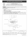
_NSTALLAT_ON AND SERVICE MUST BE PERFORMED BY
A QUAUHED _NSTALLER.
IMPORTANT: SAVE FOR LOCAL ELECTRICAL _NSPECTOR'S USE.
READ AND SAVE THESE _NSTRUCT_ONS FOR FUTURE REFERENCE.
mfthe information in this manual is not followed exactly, a fire or explosion may result
causing property damage, personal iniury or death.
FOR YOUR SAFETY:
-- Do not store or use gasoline or other flammable vapors and liquids in the vicinity of this or any other
-- WHAT TO DO [F YOU SMELL GAS:
Do not try to light any appliance.
Do not touch any electrical switch; do not use any phone in your building.
• mmmediately call your gas supplier from a neighbor's phone. Follow the gas supplier's instructions.
• mfyou cannot reach your gas supplier, call the fire department.
-- Installation and service must be performed by a qualified installer, service agency or the gas supplier.
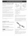
Cooktop Dimensions
30" Min.
(762 cm)
C
l
B
Cooktop Cutout Dimensions
Figure 1
All dimensions are in inches (cm),
NOTE: Wiring diagram for this appliance is enclosed in this booklet.
P/N 318201457 (0404) Rev A
English - pages 1-10
Espat_ol- p_iginas 11-19
Wiring Diagram - pages 20

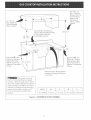
13" (33 cm)
Max, Depth For
Cabinet Installed
Above Cooktop.
A Min.
30" (76.2 cm)
Min, Clearance
Between the Top
of the Cooking
Platform and
Unprotected
Wood or Metal
Cabinet
t"
18" Min.
(45.7 cm)
Dimension J isthe Minimum
Distance Required Between Rear
of Top Panel to Adjacent
Surfaces.
Clearance
Dimension K isthe
Minimum Clearance
Required From Left
Side of Top Panel to 24"
Adjacentsurface.Combustible _
_To eliminate the risk of
burns or fire by reaching over heated
surfaces, cabinet storage space located
above the cooktop should be avoided. If
cabinet storage is provided, risk can be
reduced by installing a range hood that
projects horizontally a minimum of 5"
(12.7 cm) beyond tile bottom of the
cabinets.
Dimension H isthe
Minimum Clearance
Required From Right
Side of Top Panel to
Adjacent Combustible
Surface.
Allow Dimension L Space Below
Cooktop for Piping and Electrical
Connections.
I ¸¸ kl _ kl k (xd k
MODEL H I J I K . L
30" Models 0" (0 cm) 2" (5.I cm) 2" (5.1 cm) 8V8"(20.6cm)
Figure 2 - COUNTERTOP CUTOUT OPENING

Important Notes to the Installer
1. Readallinstructionscontainedintheseinstallation
instructionsbeforeinstallingthecooktop.
2. Removeallpackingmaterialbeforeconnectingtile
electricalsupplytothecooktop.
3. Observeallgoverning(;odesandordinances.
4. Besuretoleavetheseinstructionswiththeconsumer.
Important Note to the Consumer
Keep these instructions with your Use and Care Guide for
future reference.
IMPORTANT SAFETY
INSTRI
Installation of these cooktops must conform with local
codes or, in the absence of local codes, with the National
Fuel Gas Code ANSI Z223.1--1atest edition.
These cooktops has been design certified by CSA
International. As with any appliance using gas and
generating heat, there are certain safety precautions you
should follow. You will find them in the Use and Care
Guide, read it carefully.
• Be sure your cooktop is installed and grounded
properly by a qualified installer or service
technician.
• These cooktops must be electrically grounded in
accordance with local codes or, in their absence,
with the National EJectricaJ Code ANSI/NFPA No.
70--Jatest edition. See grounding instructions
farther in this manual
• The installation of appliances designed for
manufactured (mobile} home installation must
conform with Manufactured Home Construction
and Safety Standard Title 24CFR, Part 3280
[Formerly the Federal Standard for Mobile Home
Construction and Safety, Title 24, HUD, (Part 280)]
or when such standard is not applicable the
Standard for Manufactured Home installation 1982
(Manufactured Home Sites, Communities and Set-
Ups), ANSI Z225.1/NFPA 501-A- latest edition, or
with local codes,
• Do not store items of interest to children in the
cabinets above the cooktop° Children could be
seriously burned climbing on the cooktop to reach
items.
• To eliminate the need to reach over the surface
burners, cabinet storage space above the burners
should be avoided.
• Adjust surface burner flame size so it does not
extend beyond the edge of the cooking utensit.
Excessive flame is hazardous.
• Never use your cooktop for warming or heating
the room. Prolonged use of the cooktop without
adequate ventilation can be hazardous.
• Do not store or use gasoline or other flammable
vapors and liquids near this or any other
appliance. Explosions or fires could result.
The electrical power to the cooktop
must be shut off while gas line connections are
being made. Failure to do so could resutt in
serious injury or death.
Safety Measures o Gas Surface Units
Your new cooktop has been tested to meet the most
rigid safety standards. You can feel confident while using
it but use these safety suggestions to help avoid
accidents that can cause injury to the user or damage to
the cooktop.
Note: All safety measures listed may apply to your
model.
• Plug the unit into a 120-volt grounded outlet only. Do
not remove the grounding prong from the plug. If in
doubt about the grounding of tile home electrical
system, it is the personal responsibility and obligation
of the owner to contact a qualified electrician and
have an ungrounded receptacle replaced by a properly
grounded three-prong wall receptacle, in accordance
with the National Electrical Code. Do not use an
extension cord with this unit.
• Do not repair or replace any part of the unit unless
specifically recommended in this guide. Call a
qualified technician for all other servicing.
• Clean only the parts of tile cooktop as instructed in the
Use and Care Guide.
• Be certain all packing materials are removed from the
unit before operating to prevent fire or smoke
damage, should the packing material ignite.
Ventilating Hoods
• Clean ventilating hood frequently. Grease should not
be allowed to accumulate on hood or filter.
• When flaming foods under the hood turn the fan off.
Tile fan, if operating, may spread the flame.

Safety on the Cooktop
Do not allow dry empty pans to heat on the cooktop as
this could ruin the pan and cause a fire hazard.
Do not use a wok on the cooking surface if it is
equipped with a round metal support placed over the
burner grate. This support acts as a heat trap which
may damage the burner grate, drip bowls and burner
head. It may also cause the burner to work improperly
and create a carbon monoxide hazard.
When lowering the cooktop be careful not to pinch
your fingers. Grasp sides of the top with fingertips and
lower into position.
important: Please Read Before Continuing
This appliance and its individual shutoff valve must be
disconnected from the gas supply piping system during
any pressure testing of that system exceeding Y2psig.
This appliance must be isolated from the gas supply
pipping system by (losing its individual manual shutoff
valve during any pressure testing of the gas supply piping
system equal to or lessthan Y2psig.
These cooktops are not approved for use
with downdraft systems.
Disconnect the electrical supply before
servicing cooktops.
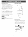
1. WanNOut_et Location
10"
(/i ¸j J
Recommended area for
120V grounded outlet
on rear wall.
22"
', NOTE: If an outlet
is not available,
have one installed by
i a qualified technician. _,
UNiT
Figure S
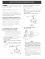
2_ Secure the Unit
Unit Clamp Down information
Once the cooktop is installed and centered in the
counter opening, you must (:lamp the unit down as
shown. To (:lamp down, insert the offset side of the
angle bracket into the slots on each side of the unit.
Then run the thumb screw through the bracket and
up against the bottom of the counter. Tighten until
the unit draws down (figure 4).
Cooktop
Countertop
Angle Bracket
Burner Box
Figure 4

3. Provide an Adequate Gas Supply
The cooktop covered in these installation instructions is
designed to operate on natural gas at 4" (10.2 cm) of
manifold pressure or on LP gas at 10" (25.4 cm) of
manifold pressure.
A convertible pressure regulator is supplied with each
surface unit and MUST BECONNECTED IN SERIES
between the supply line and the valve manifold
regardless of which type of gas is being used.
The convertible regulator for the surface units must be
located and turned in such manner to allow for easy
access to the convertible feature.
For proper operation, the maximum inlet pressure to
the regulator must not exceed 14"' (35.6 cm) of water
column (W.C.) pressure for both LPand Natural Gas.
For checking the regulator, the inlet pressure must be at
least 1" (2.5 cm) (or 2.5 kPa) greater than the regulator
manifold pressure setting. If the regulator isset for 4"
(10.2 cm) of manifold pressure, the inlet pressure must
be at least 5"(12.7 cm). If the regulator is set for 10"
(25.4 cm), the inlet pressure must be at least 11" (27.9
cm),
Tile gas supply line to the cooktops should be Y2" (!.3
cm) or 3A" (1.9 cm) pipe.
4. Connection to gas
IMPORTANT: Remove all packing material and literature
from cooktop before connecting gas and electrical supply
to the appliance.
Seal all openings in the wall behind the cooktop and in
the floor under the cooktop after gas supply line is
installed.
Install Pressure Regulator
Install the pressure regulator with the arrow on tile
regulator pointing up toward the unit in a position where
you can reach the access cap.
Do not make tile connection too tight.
The regulator is die cast. Overtightening may (:rack the
regulator resulting in a gas leak and possible fire or
explosion.
ManuaH GAS FLOW Pressu re
Shutoff Hare _€_ Hare ReguHator
Valve Union Union
On_ Nipplet r i t
Flexible Nuppe Access
Off Connector
Cap
All connections must be wrench4ightened
Figure 6
Assemble the flexible connector from the gas supply pipe
to the pressure regulator in the following order:
1. manual shutoff valve
2. 1/2" nipple
3. 1/2" flare union adapter
4. flexible connector
5. 1/2" flare union adapter
6. 1/2" nipple
7. pressure regulator
Use pipe-ioint compound made for use with Natural and
LP/Propane gas to seal all gas connections. If flexible
connectors are used, be certain connectors are not
kinked.
The supply line must be equipped with an approved
manual shutoff valve. This valve should be located in the
same room as the cooktop and should be in a location
that allows ease of opening and (:losing. Do not block
access to the shutoff valve. The valve is for turning on or
shutting off gas to the appliance.
Open position
Figure 7
Once regulator is in place, open the shutoff valve in the
gas supply line. Wait a few minutes for gas to move
through tile gas line.
Check for teaks_ After connecting cooktop gas, check
system for leaks with a manometer. If a manometer is
not available, turn on the gas supply and use a liquid
leak detector (or soap and water) at all joints and
connections to check for leaks.

Donotuseflametocheckforleaksfrom
gasconnections.Checkingfor leakswithaflamemay
resultinafireorexplosion.
Tightenallconnectionsif necessaryto preventgas
leakageinthecooktoporsupplyline.
Checkalignmentof controlknobvalvesafter
connectingthecooktoptothegassupplyto besurethe
cooktopmanifoldpipehasnotmoved.Amisalignment
couldcausethevalvestemstorubontilecontrolpanel,
resultinginagasleakattilevalve.
Disconnectthecooktopanditsindividualmanual
shutoffvalvefromthegassupplypipingsystemduring
anypressuretestingofthatsystematatestpressure
greaterthanY2psig(3.5Kpaor14"watercolum).
2.ConvertthePressureRegulatorfrom LPGasto
NATURALGas(seefigure7)
A.Removetile capfromthepressureregulator.
B.Removetheplunger.
C.Turntheplungerupsidedownwiththeenlargedend
UP.
D.Replacetheplungerinsidetheregulator.Theletters
NATor4" W.C.shouldbevisibleontheexposed
endoftheplunger.
E.Replacetilecapontile pressureregulator.
Plunger-Enlarged"_ Cap
endUPforNatural
O
Gas __._.
Isolate the cooktop from the gas supply piping
system by closing its individual manual shutoff valve
during any pressure testing of the gas supply piping
system at a test pressures equal to or less than _/2psig
(3.5 Kpa or 14" water colum).
Figure 7
Natural Gas
5. LPiPropane Gas Conversion
A. Pressure Regulator Conversion
Note: • Do not remove the Pressure Regulator.
If in doubt about the pressure at the manifold,
use a manometer. The inlet pressure on the
regulator must be at least I "' W.C. higher than
the outlet pressure. Inlet pressure on the
regulator must never exceed 14" W.C.
1. Convert the Pressure Regulator from Natural Gas
to LP Gas (see figure 6)
A. Remove the cap from the pressure regulator.
B. Remove the plunger.
C.Turn the plunger upside down with the enlarged end
DOWN.
D. Replace the plunger inside the regulator. The letters
LP or 10" W.C. should be visible on the exposed end
of the plunger.
E. Replace the
cap on the
pressure
regulator,
Cap
Plunger- Enlarged _'_
end DOWN for LP _1
Gas
Figure 6
LP Gas
B. Burner Valves Conversion
(see figure 8 and 9)
Figure 8
1. Remove valve knobs, top grates, burner pans
and lift cooktop to gain access to valves. Lo(ate
valve hoods (orifices) on back side of valves.
2a. To convert burner valves from Natural Gas
to LP Gas, use a wrench to turn valve hoods
(orifices) down until snug against the mixer pin
(approximately 2 _/2turns). Do not overtighten.
2b. To convert burner valves from LP Gas to
Natural Gas, use a wrench to turn valve hoods
(orifices) up until they are clearly away from the
mixer pin (approximately 2 Y2turns).
3. Apply gas to the burner and adjust air shutter on
burner venturi tube to proper flame (refer to
pictures in "Burner Flame Adjustment" section
for comparison).

Pini X
NaturalGas-_
Z
Hood nut
_/-- Hood
A
Gas
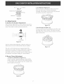
2. Too Much Air (figure 12)
If the air shutter is adjusted so that too much air
flows into the burner, the flame will appear
unsteady, will possibly not burn all the way around,
and will be noisy (like a blowtorch).
Figure 9
5. Adjustments
A. Burner Air Shutter Adjustment
The air shutter adjustment for each of the four burners is
located at the open end of the venturi tube on the valve
hood. Tile shutter is held in place by friction fit.
÷
Air Shutter
Figure 10
If the air shutter needs adjusting, rotate tile shutter to
allow more or less air to the burner tubes as needed.
Tile unit is set for Natural Gas at approximatly 50%
opening of air shutter. For flame adjustment it might be
necessary to rotate the air shutter to some point less
than 50%; for LPGas conversion the air shutter needs to
be rotated to a full open setting for a normal flame.
B. Burner Flame Adjustment
1. Proper Air Adjustment (figure !1)
If the air shutter is properly adjusted, flame will be
steady, relatively quiet, and will have approximately
Y2" sharp blue cones. With LP gas, this usuaJly occurs
when shutters are full open.
Figure 12
3. Not Enough Air (figure !3)
If the air to the burner is insufficient, you will not see
any sharp blue cones in flame. The flame may burn
with yellow tips, and soot will accumulate on utensils
used on the burner.
Figure 13
Figure 11

7° Connect Emectricity to Gas
Cooktop
Electrical Requirements
120 volt, 60 Hertz, properly grounded branch circuit
protected by a 15 amp circuit breaker or time delay fuse.
Do not use an extension cord with these cooktops.
IMPORTANT Please read carefully.
For persona! safety, these appliances must be
properly grounded.
The power cord of these appliances is equipped with a
3-prong (grounding) plug which mates with a standard 3-
prong grounding wall receptacle (see Figure 14) to
minimize the possibility of electric shock hazard from this
appliance.
The wall receptacle and circuit should be checked by a
qualified electrician to make sure the receptacle is
properly grounded.
Preferred Method / "\
Grounding
type wall
receptacle Power supply cord with
3-prong grounding plug
Figure 14
Where a standard 2-prong wall receptacle is installed, it
is the personal responsibility and obligation of the
consumer to have it replaced by a properly grounded 3-
prong wall receptacle.
Do not, under any circumstances, cut or remove the
third (ground) prong from the power cord,
If an external electrical source is used, the appliance,
when installed, must be electrically grounded in
accordance with local codes or in their absence of local
codes with the National Electric Code ANS!/NFPA No.
70-1987 or latest edition.
Check all code rules and regulations for connecting the
cooktop to be certain the installation conforms with all
local, municipal and state codes as well as local utility
regulations.
Failure to comply with tile above could
result in a serious shock hazard,
Note: All hookups and adjustment shall be performed by
qualified technicians.
Situations where appliance power cord will be
disconnected frequently. Do not use an adaptor plug
in these situations because disconnecting of the power
cord places undue strain on the adaptor and leads to
eventual failure of the adaptor terminal. The customer
should have 2-prong wall receptacle replaced by a 3-
prong (grounding) receptacle by a qualified electrician
before using the appliance.
Disconnect electrical supply cord from
wall receptacle before servicing cooktop.
8. Check Operation
Refer to the Use and Care Guide packaged with the
cooktop for operating instructions and for care and
cleaning of your cooktop.
Do not touch the burners. They may be hot enough to
cause burns.
.
Check the Igniters
Operation of electric igniters should be checked after
cooktop and supply line connectors have been
carefully checked for leaks and the cooktop has
been connected to electric power.
To check for proper lighting, push in and turn a
burner knob to the LITEposition. The burner should
light when gas is available to burner. Once the
burner lights, the burner knob should be turned out
of the LITEposition. Try each knob separately until
all burners have been checked out.
The burners can be tit manually during an
electrical power outage. To light a burner, hold
a tit match to the burner head, then slowly turn
the Surface Control knob to LJTE. Use caution
when lighting burners manually,
Surface burner in use when an electrical power
failure occurs will continue to operate normally.
The surface burners on models equipped with pilots
can operate during an electrical power outage.

.
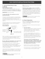
Adjust the "LO" or "SIMMER" Setting of Surface
Burner Valves (see Figure 15}
Push in and turn each control knob to the "LO" (or
"SIMMER") setting. The"LO" setting of each
burner has been set at the factory to the lowest
setting available to provide reliable reignition of the
burner. If it does not stay lit on the"LO" setting,
check the setting as follows.
_Be extremely careful when performing
this operation.
A. Allow cooktop to cool to room temperature.
B. Light all burners by turning each control knob to
LITEuntil burners ignite, and then set them at
"HI".
C. _turn the knob to tile LOWESTPOSITION
for the burner you want to adjust.
D. If burner goes out, readjust valve asfollows:
Remove the surface burner control knob, insert a
thimbladed screw driver into the hollow valve
stem and engage tile slotted screw inside. Flame
size can be increased or decreased with tile turn
of the s(rew. To increase flame size turn the
s(rew counterclockwise and to decrease turn
clockwise. Adjust flame until you (:an quickly
turn knob from HI to LOWESTPOSITIONwithout
extinguishing tile flame. Flame should be as
small as possible without going out.
E. If you need to adjust another burner, repeat the
steps from A to D above until all burners operate
properly.
Valve Stem
Figure 15
When All Hookups are Complete
Make sure all controls are left in the OFF position.
Make sure the flow of combustion and ventilation air to
the cooktop isunobstructed.
Model and Serial Number Location
The serial plate is located into the burner box near the
burner support or under the burner box.
When ordering parts for or making inquires about your
range, always be sure to include tile model and serial
numbers and a lot number or letter from the serial plate
of your cooktop.
Your serial plate also tells you the rating of the burners,
tile type of fuel and the pressure the cooktop was
adjusted for when it left tile factory.
Improper installation adjustment,
alteration, service or maintenance can cause injury
or property damage. Refer to this manual. For
assistance or additional information consult a
qualified installer, service agency, manufacturer
(deater) or the gas supplier.
Stepping, leaning or sitting on these
cooktops can result in serious injuries and also
cause damage to the cooktop.
Be sure to keep appliance clear of combustibJe
materials, gasoline and other flammable vapors and
liquids.
Before You Call for Service
Read the Before You Call for Service Checklist and
operating instructions in your Use and Care Guide. It
may save you time and expense. Tile list includes
common o(currences that are not the result of defective
workmanship or materials in this appliance.
Refer to your Use and Care Guide for Sears service
phone numbers, or call 1-800-4-MY-HOME ®, Pleasecall
if you have inquiries about your product and/or need to
order parts.
Cooktop Removal
If removing the cooktop is necessary for cleaning or
maintenance:
1.Shut off gas supply.
2.Disconnect the gas and electric supply.
3.Remove the installation screws which secure the unit
to the cabinet at the front and rear or the mounting
brackets on the right and left side of the burner box.
4.Remove the unit for servicing and cleaning.
Reinstall in opposite manner and order of removal and
check gas connection for leaks.

Notes
10

LA INSTALAaON Y EL SERVlaO DEBEN SER REAUZADOS
POR UN INSTALADOR CAUHCADO°
IMPORTANTE: GUARDE ESTAS INSTRUCaONES
PARA USO DEL INSPECTOR ELECTR_CO LOCAL.
LEA Y GUARDE ESTAS INSTRUCaONES PARA FUTURAS REFERENaAS
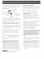
__ Si todas [as instrucdones de 6ste manual no son observadas a [a [etra, se puede ocurrir
incendios o exp[osiones que pueden causar da_os materiales, [esiones o [a muerte.
PARA SU SEGURIDAD:
-- No almacene o uti[ice gasotina u otros vapores y [iquidos inflamables cerca de este o cualquier otro
artefacto.
-- QUE HACER StHAY FUGAS DEGAS/E
No intente de encender ningun artefacto
No toque ningun interruptor e[@trico; no utilice ningun aparato t6J6fonko en su edifido.
Llame inmediatamente el abastecedor de gas desde el tel6fono de un vedno. Siga las instrucdones dem
abastecedor de gas.
En caso que no puede contactar el abastecedor de gas [lame al departamento de bomberos.
-- La instalad6n y el servido t6m6fonico deben set realizados por un instamador caJificado, por un servido
tecnico certificado o por el abastecedor de gas.
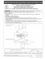
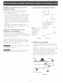
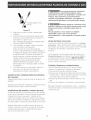
Dimensiones de la plancha
de cocinar a gas
C
30" Min.
(76.2 cm)
Dimensiones del hueco para
la plancha de cocinar a gas
Todas las dimensiones se dan en pulgadas (cm). P/N318201457 (0402) Rev A
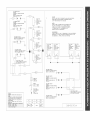
NOTA: Se adjunta los diagramas de cables de esta pJancha de cocinar con et tiberta. English- pages 1-10
Espaflol- p_ginas 11-19
Diagramade la instaladonal_mbrica- pages 20

Max. profundidad .....
de
gabinetes
A Min. _]
instalados por
encima de la
plancha de
empotar es 13"
(33 cm).
Dimensiones J este minimo
distancia entre el borde posterior
del hueco y lamas cerca
superficie combustible pot
encima del mostrador.
Espacio
30" (76.2 cm)
Minimo entre la
parte superior de la
plataforma
de la plan(ha de
cocinar y el fondo
de una madera
non protegida o
armario metalico.
Dimensiones K este
espacio minimo desde
el lado izquierdo de
almacenamiento de
combustible.
24" (61 cm)
\
Dimensiones H este
espacio minimo desde
el lado derecho de
almacenamiento de
combustible.
_-__ Para eliminar el riesgo
de alargar sobre los unidades en
calentamiento de la superficie, deber[a
evitarse el espacio de almacenamiento
del armario, ubicado sobre lasunidades
delasuperficie. Sisecuentacon este
espacio, se puede disminuir el peligro
instalando una cubierta de cocina que se
extienda horizontalmente en 5" m[nimo
got sobre la parte inferior delantera en los
armarios.
No es posible utilisar cajones (:on esta plancha
de cocinar porque la caja de empalme se
extiende de [ dimensiones pot encima de la
superficie del mostrador.
MODELO H I J I K L
Modelos 30" 0" (0 cm) 2" (5.1 cm) 2" (5.1 cm) 81/8``(20.6cm)
Figura 2 - DESENO DEL ARMARtO
12

Notas importantes para el instalador
1. Leatodas los instrucciones de instalacion antes de
realizar la instalacion de la plancha de cocinar.
2. Retire todos los articulos de embalaje antes de realizar
los conexiones el6ctricas a la plancha de cocinar.
3. Observe todos los codigos o reglamentos estatales
4. AsegL]reseque el consumidor tenga estas instrucciones.
Notas importantes para el consumidor
Guarde todas losinstrucciones con su manual del usuario
para futuras referiencias.
INSTRUCCIONES DE
SEGURIDAD IMPORTANTES
La instalacion de esta plancha de cocinar debe realizarse
en conformidad con los cOdigos locales o, si 6stos no
existen, con el National Fuel Gas Code ANS! Z223.1
(dtima ediciOn.
El diseflo de esta plancha de cocinar cuenta con la
aprobacion de la CSA International. AI igual que todos los
artefactos a gas que generan color, deben seguirse ciertas
medidas de seguridad. Vienen con el Manual de uso y
mantenimiento. Lea el manualatentamente.
Asegure que ta plancha de codnar sea instalada
correctamente pot un instalador o t_cnico
calificado.
• La plancha de codnar debe conectarse
el_ctr[camente a tierra de acuerdo con los c6dlgos
locales o, de no existir, con el c6digo el_ctrico
ANSI/NFPA No. 70 - _[tima edid6n. Mire los
instrucdones de conexi6n a tierra.
• La [nstalacl6n de tas unldades diseffados Data
casas (moviles) deben estar de acuerdo con:
"Manufactured Home Construction and Safety
Standards tittle 24 CFR, part of 3280
(antedormente The Federal Standard for Mobile
Home Construction and Safety, tittle 24, HUD, Part
280)", o cuando los estandares no son aplicabIes
the "Standard for Manufactured Home Installation
1982 (Manufactured Home Sites, Communities and
Set-ups ) ANSI Z225.1-NFPA- 501A" o _[tima
edici6n o con los c6digos locales.
• No almacene art_culos que interesan los nitros en
los armarios que est_n pot encima de [a p[ancha
decocinar. Lespodriacausarquemadurasgravassi
intentan subirse para alcanzarlos.
Deber&n eIiminarse [os armarios sobre [os
quemadores para evitar e[ contacto entre ambos.
• Grade el tamaffo de ta [[ama de modo que no
sobrepase e[ borde de[ ustensiIio de ta plancha de
cocinar.
No utilice jam_s su p[ancha de cocinar como
calefactor. Elusoprolongadodelacocinasinla
ventilaci6n adecuada puede set peligroso.
• No guarde o haga uso de gasolina o otros
vaporos y t[quidos infJamabIes acerca de est_ o
cua[quieraparato. Sepuederesultaren incendioso
explosi6nes.
V!_ El sumlnistro e!_ctrico a la plancha
de codnar debe de set cerrado durante tas
conexiones a [a tlnea. De to contrario se puede
resuItar [esiones graves o [a muerte.
Recomendaciones de seguridad para
unidades de superficie
Su nueva plancha para cocinar ha sido probada para
cumplirlosmasaltosestandaresdeseguridad. Usted
puedesentirseseguroalusarla. Perosigalassiguientes
recomendaciones de seguridad para evitar accidentes
que puedan lastimar a quien Io usa o darlar de la
plancha de cocinar.
NOTA: Algunas recomendaciones de seguridad pueden
no aplicar a su modelo.
Conecte la unidad unicamente a un toma de 120
voltiosconconexionatierra. Siexistealgunaduda
acerca de la conexion a tierra del sistema el6ctrico de
la casa, es responsabilidad y obligacion del duerlo
contactar a un electricista calificado y hater
reemplazar el toma sin tierra por un toma de tres
patas conectado a tierra que siga el National Electric
Code. Conestaunidadnodebenusarseextensiones.
No repare o reemplaze ninguna porte de la estufa a
menos que se recomiende en forma expl[cita en este
manual. Llamea unt6cnicocalificadoparacualquier
otro tipo de servicio.
Limpie unicamente los partes de la estufa come se
recomienda en la Guia de Usuario.
Aseg0rese de que todos los materiales de empaque
ban sido removidos de la unidad antes de usarla, para
prevenir darlo por fuego o humo en caso de
incendiarse el material de empaque.
Extractores de aire
Limpielosextractoresfrecuentemente. Nosedebe
dejar acumular grasa en el extractor o en el filtro.
o Cuando los alimementos esten dando llama, apague el
extractor; estepuedeexpandirlallama.
13

Medidas de seguridad para e[ uso de [a
p[ancha de codnar
• No coloque recipientes de cocina secos y ratios
encima de las parillas pues esto los dar]arla y se
correrfa peligro de incendio.
• No use un wok (sart_n chino) en la plancha de cocinar
sivienecon elanillomet_licoparasostenerla. Este
anillo actua como una trampa de calor que puede
danar la parrilla del quemador, las cocas y el mismo
quemador. Ademaspuedehacerqueelquemador
funcionemal. Estopuedegenerarnivelesindeseados
de monoxido de carbono que serfan perjudiciales para
la salud.
• Aseg0rese de no lastimarse los dedos al cerrar la
planchadecocinar. Sujetelaplanchacon laspuntas
de los dedos y bajela.
Importante : Pot favor lea antes de
continuar con la instalacion
El aparato y su vdvula de apagado deben ser
desconectados del sistema de suministro de gas durante
cualquier prueba de presion del sistema a una presion de
prueba en exceso de 1/2 psig.
La unidad debe estar aislada del suministro de gas
cerrando la vdvula manual de cierre durante cualquier
prueba del sistema del suministro de gas a una presion
de prueba igual o menor que 1/2 psig.
Esta cocina no debe de usar con sistemas
de ventilaci6n descendente.
Desconecte la corriente electrica antes
de hacer mantenimiento a este electrodomestico.
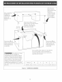
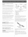
1. Area para la toma de corriente
NOTA: Si no existe
una toma de
corriente, contacte a
un electricista
calificado para
realizar la
instalaci6n.
12"
1 0.5cm)-*
; 10"
m (25.4 cm)
I Area recomen
' la toma de corriente a
I tierra de 120V en el
, pared posterior. 22"
CL de pared (55.9 cm)
' y unidad
Figura 3 "CL de suelo
2_
Fijacion de la unidad
Una vez que el aparato esta instalado y centraro en
la apertura del mostrador, se tiene que sujetar como
se indica.
Para ajustar el aparato, inserte el soporte, con el lado
desviado, en la ranura en cada Iodo del aparato. El
tomillo que se puede girar con los dedos debe
entonces de pasar a tray,s del soporte y hasta la
partedeabajodelmostrador. Apri_telohastaqueel
aparato se quede ajustado (yea la figura 4).
Plancha de
cocinar
Mostrador
1
Brida de fijacion
Tornillo
Caja del quemador
Figura 4
14

3. Provea un adecuado suministro
de gas
Las planchas de cocinar abarcadas en estas instrucciones
de instalacion estan diser-ladas para funcionar con gas
natural de 4" (10.2 cm) de m(dtiple de admision o (;on
gas propano de 10" (25.4 cm) de mL]ltiple de admision.
Se conecta un regulador de presiOn convertible en serie
al m(_ltiple a la cocina que debe permanecer en serie
con la Ilnea de suministro de gas, que no tiene en
cuenta siesta utilizado gas natural o gas propano.
El regulador convertible de las planchas de empotrar
debe set Iocalizado y colocado de tal forma que permita
el acceso a la caracter[stica de set convertible.
Para un manejo correcto, la presion de entrada
maxima hacia el regulador no debe exceder 14" (35.6
cm) de presiOn de la columna de agua.
Para controlar el regulador, la presion de entrada debe
set de al menos 1" (2.5 cm) (o .3.4 kPa) mayor que el
ajuste de presion del m01tiple del reglador se ajusta a 4"
(10.2 cm) de la presion del mL]ltiple, la presion de
entradadebeserdealmenos5" (!2.7 cm). Siel
regulador se ajusta a 10" (25.4 cm), la presi0n de
entrada debe set de al menos 11 " (27.9 cm).
La I[nea de suministro de gas por la cocina debera tenet
un tubo de Y2" (1.3 cm) o 3A" (1.9 cm).
4. ConexiOn del gas
IMPORTANTE: Retirar todo el material de empaque y la
literatura de la cocina antes de conectar el suministro de
gas y de electricidad al aparato.
Selle todas las aberturas de la pared detras de la
plancha de cocinar yen suelo por debajo de la plancha
de cocinar despues la instalacion del suministro de gas.
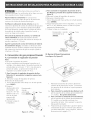
Instalar el regulador de presion
tnstalar e! regutador de presiOn con la flecha del
regulador apuntando hacia la pieza yen una position
que permita alcanzar la tapa de entrada.
__ No aiuste demasiado la conexiOn. El
regular esta fundida a presiOn. AI aiustar demasiado se
puede romper el regulador causando una fuga de gas y
un posible incendio o explosion.
VaHvuHade FLCUO DEL GAS ReguHator
derre Uni6n Uni6n de presi6n
manual
Ablerto, _ t t 1
(on) k._ Boquilla Conector Boquill_ I
Apagado flexible Tapa de
(Off) entrada
Todas las conexiones deben ajustarse con
una Ilave de tuerca
Figura 5
Monte el conector flexible del tubo del suministro de gas
al regulador de presi0n en funcionamiento:
I. vdvula de cierre manual
2. boquilla de I/2"
3. adaptor de 1/2"
4. conector flexible
5. adaptator de I/2"
6. boquilla de I/2"
7. regulador de presion.
Utilice un compuesto de tubo articulado para uso de gas
natural y propano para sellar todas las conexiones de gas.
5i se utilizan conectores flexibles, aseg(Jreseque los
conectores no estan torcidos.
El tubo de suministro de gas debreria incluir una vdwJla de
cierre certificada. Esta valvula deberia estar ubicada en la
misma habitaci01n de la plancha de coninar y deberia estar
en un lugar que permita una abertura y cierre faciles. No
bloquee las entradas de la valvula de cierre. La valvula
sirve para abrir o cerrar el paso del gas al artefacto.
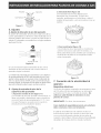
Abierta
Figura 6
Abra la valvula de cierre en el tubo de suministro de gas.
Espere unos minutos para que el gas pase a trav_s del
tubo de gas.
Verifiqueparatasfugas. Luegodeconectarla
plancha de cocinar al gas, verifique el sistema (:on un
manometro. Si no cuenta con este instrumento, cortar
todos los pilotos y d6 la vuelta al suministro de gas de la
plancha de cocinar y utilice un detector de fugas I[quidas
en todas las articulaciones y conexiones para verificar si
existen fugas.
15

Noutilicellamalibreparaverificarla
existenciadefugas.Laverificaci6ndelasfugasconuna
llamapuedeprovocarfuegooexplosi6n.
Ajustetodastasconexionesencasoquesea
necesario,paraevitarfugasdegasenlaplanchade
cocinaroeneltubodesumininistrodegas.
Verifiquetaalineaci6ndetasvStvulasluegode
conectarlaplanchadecocinaralsuministrodegaspara
asegurarquenosehamovidolavalvuladelm01tiple.
Unamalaalineaci6npuedeinducirlafriegadeltronco
deperilladelavalvulasobreel paneldecontrol,y
ocurrirenfugasenlavalvula.
Desconectelaplanchadecodnary suv_lvulade
derreindividualdelsistemadetuberiadurante
cualquierensayodepresi6ndelsistemaenensayosde
presi6nsuperioresa1/2psig.
Aparte[aplanchadecodnarde[sistemadetuber_a
delsuministrodegas,cierrandosuvalvuladecierre
individualmanual,durantecualquierensayodepresi6n
delsystemadesuministrodegasenensayosigualeso
inferioresa I/2 psig.
5. Conversi6n de gas propanoilicuado
A. Conversi6n el regulador de presi6n
Nota:
No quite el regulator de presi6n.
Use un man6metro para chequear la presi6n en el
multiple, sihayalgunaduda. Recuerdelapresi6nde
entrada debe ser al menos 1" W.C. mas alta que la
presi6ndesalida. Lapresi6ndeentradaenal
regulador nunca debe exceder 14" W.C.
1. Para Convertir el regutador de presi6n de Gas
Natural a LP, proceda de [a siguinte manera (vea
f[gura 6)
A. Remueva la tapa del regulador de presi6n.
B.Remueva el desatascador.
C. Gire el desatascador hacia abajo con el lado grande
hacia ABAJO.
D.Ponga el
desatascador entre
el regulador. Las
letras LP o 10" WC
deberan estar a la
vista en la parte
expuesta del
desatascador.
E.Coloque la tapa en
el regulador.
Desatascador
Grande
extremidad _€_ Tapa
hacia ABAJO, _
Figura 6 - LP Gas
2. Para Convertir el regulador de presi6n de LP a
Gas Natura[, proceda de ta siguinte manera (yea
figura 7)
A.Remueva la tapa del regulador de presi6n.
B.Remueva el desatascador.
C.Gire el desatas(ador hacia arriba con el lado grande
hacia ARRJBA.
D.Pongaeldesatas(adorentreelregulador. Lasletras
NAT o 4" WC deberan estar a la vista en la parte
expuesta del desatascador
E.Colique la tapa en el regulador.
Desatascador-Grande _ Tapa
extremidad hacia -_[9ARRtBA.
0
Figura 7
Gas Natural
B. Burner Valves Conversion
(yea figura 8 y figura 9)
Figura 8
1. Remueva los botones de control y [evante [a
cubiertadelaplanchadecocinar. Encontrara
las capuchas de la vdwJla en la parte posterior
de la valvula.
2a. Para convertir Ja unidad de Gas Natural a LP,
gire la capucha de la valvula aproximadamente
2 _/2wJeltas. No apriete demasiado.
2b. Para convertir [a unidad de LP a Gas Natural,
gire la capucha de la valvula aproximadamente
2 _/2vueltas en el sentido contrario a las
manecillasdel reloj. Estosepararalacapucha
del pasador mezclador.
3. Proporcione gas al quemador y ajuste el piloto y
el obturador de gas en el venturi para obtener
unallamaadecuada. (paracomparar, utilicelos
illustracionsdelapagina 17).
16

Pasador-N _ Capucha
GasNatural-_
Figura9
LP
6. Ajustes
A. Ajustes de obturador de aire del quemador.
El ajuste del obturador de aire para cada uno de los
cuatro quemadores y del horno esta Iocalizado en el
extremo abierto del venturi y ajusta la capucha de la
valvula, El obturador se mantiene en su lugar mediante
ajuste por friction.
Ajuste d_eaire
Figura 10
En caso de necesitar ajuste el obturador de aire, rote el
obturador de aire para permitir mas o menos aire en el
quemador (seg0n senecesite).
La unidad esta preparada para Gas Natural a una abertura
deaproximadamentee150% delobturadordeaire. Para
ajustar la llama puede ser necesario rotar el obturador de
aire a un punto menor al 50%; para la conversion de gas
propano liquido, el obturador de aire debe ser girado hasta
que este totalmente abierto para una llama normal.
B_
Ajuste de entrada de aire de la
superficie del quemador
1. Ajuste de entrada de aire (figura 11)
Si la entrada de aire esta ajustada correctamente, la
llama sera estable, relativamente suave y tendra un
cono azul fuerte de aproximadamente Y2" (1.3 cm).
Con gas LP propano, se puede ocurrir cuando la
entrada de aire esta totalmente abierta.
Figura 11
2. Demasiado Aire (figura 12)
Si el obturador de aire esta dejando pasar
demasiado aire al quemador, la llama sera
inestable, posiblemente no habra llama a todo el
rededor del quemador, y esta sera ruidosa (como un
soplete).
Figura 12
3. Aire insufidente (figura 13)
Si la entrada de aire al quemador es insuficiente,
usted no vera COHOSazul fuerte en la llama. La
llama podra tenet puntas amarillas que causar[an la
acumulacion de hollln en los recipientes usados
sobre el quemador.
F[gura 13
7. Conexion de la electriddad al
aparato
Requisitos elOctricos
Un circuito de cafler[as conectado correctamente a tierra
de 120 voltios, 60 Herz protegidos por un interruptor
automOtico de 15 amp o un fusible de retardo. No
utHice un cab[e flexible de extensi6n en esta
p[ancha de codnar.
tMPORTANTE: Por favor, lea atentamente.
Como medida de seguridad personal, este artefacto
debe conectarse a tierra correctamente_
El cable de encendido de este artefacto incluye un
enchufe de tres patas (de conexion a tierra) que calza
con un enchufe de pared est_ndar de tres patas de
conexiOn a tierra (Figura 14) para disminuir la posibilidad
de peligro de choques electricos desde el artefacto.
17

Seaconsejaalconsumidorqueunelectricistacalificado
verifiqueelenchufedeparedyelcircuitoparaasegurar
queelenchufeesteconectadoatierracorrectamente.
IVl_todo Preferido f -"
Enchure
de pared a
tierra
Cablo de encendido
con enchufe de tres
patas a tierra
Figura !4
En caso de encontrarse con un enchufe de pared
esd_ndar de dos patas, es la personal responsibilidad y la
obligaciOn del consumidor reemplazarlo por el enchufe
de pared de tres patas correspondiente.
No debe, bajo ninguna drcunstanda cortar o retirar
ta tercera pata (tierra) del cabJe de encendido.
Si una fuente de electricida es utilizada; el aparato debe
ser conectado a tierra de acuerdo con las normas locales
o de acuerdo las "National Electrical Code", ANS!/NFPA
NO. 70-1987 o ultima edici6n.
Verifique todos los c6digos, normas o regulaciones para
conectar el aparato para cerciorarce de que la
instalaci6n esta de acuerdo a los c6digos locales,
estatales y de las empresas de servicio de energ[a
locales.
El incumplimentode las anteriores recomendaciones,
puede resultar en un peJigroso choque el_ctrico.
Nota: Todas las conexiones deben ser hechas pot
tecnicos calificados.
Situadones donde e! cord6n de aHmentaci6n de!
e[ectrodom_stico debe de set frecuentemente
desconectado. No use un tapOn adaptador en estas
situaciones porque desconectar frecuentemente el cordon
de alimentaciOn genera demasiado tirantez sobre el
adaptador y puede causar el real funcionamiento del borne
del adaptador. Esla responsabilidad del propietario de
asegurarse que un electricista calificado reemplaza una
tomacorriente de dos patas pot una tomacorriente de tres
patas (puesta a tierra), antes de usar el electrodom6stico.
Desconecte el cable elOctrico del toma
de la pared antes de hacer mantenimiento.
8. Verifique la operad6n
Refiera el Manual del usuario que viene (on la plancha
de cocinar para las instrucciones de funcionamiento y el
mantenimiento y la limpieza de su plancha de cocinar.
No toquealosquemadores. Puedenestar
suficientemente calientes par causar quemaduras.
1.
Verifique los dispositivos de encendido
(algunos modelos}
La manipulation de los dispositivos de encendido
elOctrico deberan verificarse tras haber revisado
detenidamente la plancha de cocinar y los
conectores del tubo del suministro de fugas y tras
haber conectado la plancha de cocinar al suministro
electrico.
Para verificar el correcto encendido, presione hacia
adentro y gire una valvula de quemador superior
hasta la posici6n "ENCENDIDO" (LITE). El
quemador debe encender cuando tiene gas
disponible. Unavezelquemadorencienda debe
cambiarse a una posici6n diferente a "ENCENDIDO"
(LITE). Cadavalvula debechequearse
independientemente hasta que todos los
quemadores hallan sido revisados.
Durante un corte de energ[a el_ctrica se pueden
encender los quemadores de ta cubierta con una
cerilla. Acerque una ceri[la encendida a[
quemador y [uego gire tentamente e[ bot6n a [a
posici6n ENCENDDO (LITE}. Tenga extremo
cuidado a[ encender los quemadores en esta
forma.
Los quemadores de parrilla que est6n encendidos
cuando ocurra el torte de energia electrica seguiran
funcionando normalmente.
28
Verificar el ajuste "LO" o "SIMMER" (Planchas de
cocinar 30" solamente} (yea Figura 15)
Presionar y girar el bot6n de control al ajuste "LO"
(o "SIMMER"). Elajuste "LO" decadaquemador
ha sido creado para fijarse al menor ajuste
disponible para entregar un reencendido confiable
delquemador. Si noquedaencendidoenelajuste
"LO", verificar el ajuste "LO" como se muestra a
continuaci6n.
18

agujerodela
Figura! 5
A. Deiarquelacocinaseenfr[eatemperatura
ambiente.
B. Encendertodoslosquemadoresgirandocada
bot0ndecontrolhastaLITEparaencenderlos
quemadoresyfijarlosenHI.
C. Girarrapidamenteelquemadorutilizadodesde
HIhastaLOWESTPOSITION.
D. Sielquemadorseapaga,reajustarlavalvula
comosemuestraacontinuaci6n:
Retirarelbot6ndecontroldelquemador,
insertarundestornilladordecuchillodelgadoen
elvastagodelagujerodelavalvulayencajarel
tornilloranurado.EItamaFlodelallamase
puedeaumentarodisminuirgirandoeltornillo.
Graduarlallamahastaquesepuedagirar
rapidamentehaciaabajodesdeHIhasta
LOWESTPOSITIONsinapagarlallama.La
llamadeber;_serIom4sbajaposibleyestable
sinapagarse.
E. Sisedeseaajustarotroquemador,repetirlos
pasosdeAaDdescritoshastaquelos
quemadoresfuncionencorrectamente.
Cuando se hart realizado todos los sistemas
de conexi6n
Asegurese que todos loscontroles estan en la position de
apagado.
Asegurese que el flujo de combustion y ventilation de aire
de la plancha de cocinar no esten obstruidos.
Localizacion del modelo y numero de serie
La place de serie de su plancha de cocinar esta ubicada
en la caja del quemador, cerca del soporte de quemador
odebajodelacajadequemador. Ademas de los
nOmeros de modelo y de serie, contiene la informacion
acerca de la potentia normal de los quemadores, el tipo
de combustible y el aiuste de presion fijado en la fabrica.
Aseg0rese de incluir el modelo, n0mero de serie y el
m]mero o letra del note que se encuentran en la placa,
en todo pedido de partes o solicitud de informaci6n
acerca de su plancha de cocinar.
lncorrectas ajustas de instatad6n,
modificati6nes y reparad6nes pueden causar
quemaduras o da_os a Ja propiedad. ConsuJte est_
manuaJ. Para asistenda y m_s informad6n,
consuJte un instaJador calificado, una agenda, Ja
fabricante (distribuidor) o et suministrador de gas.
_.__ Paraese, apoyarse o sentarse en las
puertas o caiones de esta estufa puede causar serias
tesiones personates y tambi_n puede da_ar ta
estufa.
No use gasoJina u otros vapores o tiquidos
inflamables cerca a este u otto aparato
eJectrodom_stico. Una explosi6n o incendio podrla
ocurrir.
Antes de llamar al servicio
Lea la section Lista de Control de Aver[as en su Manual
delUsuario. Estolepodraahorrartiempoygastos. Esta
lista incluye ocurrencias comunes que no son el resultado
de defectos de materiales o fabricaci6n de este
artefacto.
Lea la garantia y la information sobre el servicio en su
Manual del Usuario para obtener el n0mero de telefono
y la dirrecion del servicio o Ilamar 1-888-SU-HOGAR sM.
Pot favor Ilame o escriba si tiene preguntas acerca de su
estufa o necesita repuestos.
Cuidado, limpieza y mantenimiento
Cierre el suministro de gas en caso de set necsario
remover la unidad para su limpieza o reparation:
1.Desconecte la I[nea de suministro de gas.
2.Remueva los tornillos de instalaci6n del marco frontal y
parrillainferior. Halehaciaafueraapenaslonecesario
para poder desconectar del toma el6ctrico.
3.Despues de desconectar del suministro el6ctrico y de
gas
4.Remover la unidad para su limpieza o mantenimiento.
Reinstale siguiendo el procedimiento inverso. AsegOrese
de nivelar la estufa y verificar que no halla escapes en la
conexion de gas.
19

TOP BURNER IGNITER
OPTIONAL
QUEMABOR BE ENCERDIDO SUPERIOR
OPCIONAL
BOUGIE O'ALLUMAOE-BRULEOR
FACULTATIP_---
E I
E TOP BURNER IGNITER
OPTIONAL
l QUEMABOR DE ENCENmDO SUPERIOR
I OPCIONAL
i BOOGIE O'ALIOMAOE-BRULEUR
I FACULTATIF--
' {* 4}
IF---
E ..... _
Et
i!
'I
i
E _
E _
E _
'I
E
E
E
E E
E
E _
i ..... <)i
TOP BURNER IGNITER
QUEMADOR BE ENCENDIDO SUPERIOR
BOOGIE D'ALLOMAOE-BRULEUR
RIGHT REAR
iON SW
iNT ERC TRASERO
DERECHO
INTER,ALLOM,
OAR
LEF REAR
iON BW
TOP BURNER iGNITER
QUEMADOR BE ENCENDIDO SUPERIOR
BOOGIE B'ALLOMABE-BRULEUR
BLOC CONNECIION ALLUMEUR
© LO--__--
i
i
E
i
E © _ NO-----
WARNING
DISCONNECT POWER BEFORE SERVICING UNIT
AVISE
BESCONECTE LA ENEROIA ANTES BE REALiZAR
EL MANTENIMIENTO BEL ELECTRODOMESTIO0
OIBCONNECT POWER BEFORE SERVICING UNIT¸
_IBSEMENT
CO0_ER LE COURAN_ AVANT B'EFFECTUER LA
REPARATION,
COLOR CODE / CODIGOS DE COLOR / CODE COULEOR
BKIILABK / NEGRO / NOIR
W I WHITE / BLANCO / BLANC
R RED / ROJB / RBUBE
\
\
NT ENC TRASERO
IZQUIERO0
INTER ALLOM,
GAR
[NT ENC, DE
FRENTE IZOOiERDO
INTERALLUM
GAV
RIGHT FRONT
ION S_!INT ENC DE
FRNTE DERECH
INTER ALLUM
D,AV
i
CONNECIOR
CONECTOR
CONNECTEUR
GROUND
PUESTA A T[ERRA
MiBE A LA TERRE
POWER CORD
PARA TRANSPORTE
DE FUERZA
CABLE
D'ALiMENTATION
2 i 18
o
i m
WIRE GAGE
AL2MBRE MEDIDA
CAL
200
150
TEMP_C
3304
3301
UL STYLE
MOBO UL
STYLE UL
CAUTION_
LABEL ALL WIRES PRIOR TO DISCONNECTION WREN SERVICING CONTROIS
WIRING ERROR CAN CAUSE IMPROPER AND BANGEROO_ OPERATION
VERIFY PROPER OPERATION AFTER SERVICING
AVISO:
ETIQUETE TODOS LOS ALAMBRES ANTES DE DESCONECTAR PAR
REALIZAR ET MANTENIMIENTO DE LOS CONTROLESERROR DE
ALAMBRAJE PUEDE CAUSAR UN FUNCIONAMIENTO iNCORRECTO
Y PELIOROBOVERIQOE SI EL FONC[ONAMIENTO ESTA
CORRECTO DESPUES BEL MANTENIMIENTO
AVER [ISSEMENT:
ETiQUETER CHAQUE FIL AVANI LE BEBRANCHEMENI DE CEUX-CIUNE ERREUR BE
BRANCREMEN[ PEUT CAUSER UNE OPERATION DANOEREOSEVERiF]ER LE BON
FONCTIONNEMENT DE L'APPAREIL APRES TQUTE REPARATION
R_GHT FRONT
IGNSW
]NTENC DE
FRENTE DERECHO
INTERALLUM
BAV
LEFT FRONT
[ONSW
INTENC DE
FRENTE IZQUIER_O
INTERALLUM.
GAV
LEFT REAR
IONSW
INTENCTRASERO
IZQUIERDO
INTER,ALLUM
OAR
lOP BURNER IGNI[ER
QOEMADOR DE ENEERmDO SUPERIOR
BOUOIE D'ALLUMAOE BRULEUR
TOP BURNER IGNITER
OPTIONAL
QUEMADOR DE ENCENDIBO SUPERIOR
OPCIONAL _BOOGIE D'ALLUMAGE-BRULEOR -- -__
FACULTATIF
TOP BURNER IGNITER
OPTIONAL
QUEMABOR DE ENCENDIDO SUPERIOR
OPCIONAL _BOOGIE O'ALLOMAGE-BRULEUR -- -__
FACULTATIP
-©? NO
RIGHT REAR
IONSW
NT ENC [RASERO
BERECHO
INTER ALLUM
DAR,
L ___
N
TOP BURNER IGNITER __
QUEMADOR BE ENCENDIDO SUPERIOR
BOUGIE D'ALLUMAGE BRULEUR
IGNITER MODULE BOARB
OOABRO DE MODULO DE ENCENBiBO
BLOC CONNECTION ALLUMEUR
318047105 R,_V,A
-
 1
1
-
 2
2
-
 3
3
-
 4
4
-
 5
5
-
 6
6
-
 7
7
-
 8
8
-
 9
9
-
 10
10
-
 11
11
-
 12
12
-
 13
13
-
 14
14
-
 15
15
-
 16
16
-
 17
17
-
 18
18
-
 19
19
-
 20
20


Kenmore 79032092400 Guía de instalación
- Categoría
- Cocinas
- Tipo
- Guía de instalación
En otros idiomas
Documentos relacionados
Otros documentos
-
Frigidaire FGGC3645QB Guía de instalación
-
Frigidaire FGC30S4DBA Guía de instalación
-
-
-
-
-
-
GE Profile JGP930SEASS Guía de instalación
-
Frigidaire LEGC36S9FEA Guía de instalación
-
GE JGP960SEASS Guía de instalación