
©
2006 Sony Corporation Printed in Taiwan
2-696-858-42 (1)
Cautions
• This unit is designed for negative ground (earth) 12 V
DC operation only.
• Do not get the leads under a screw, or caught in moving
parts (e.g. seat railing).
• Before making connections, turn the car ignition off to
avoid short circuits.
• Connect the yellow and red power supply leads only
after all other leads have been connected.
• Run all ground (earth) leads to a common
ground (earth) point.
• Be sure to in su late any loose un con nect ed leads with
electrical tape for safety.
Notes on the power supply lead (yellow)
• When connecting this unit in combination with other
stereo components, the connected car circuit’s rating
must be higher than the sum of each component’s fuse.
• When no car circuits are rated high enough, connect
the unit directly to the battery.
Parts list
• The numbers in the list are keyed to those in the
instructions.
• The bracket and the protection collar are
attached to the unit before shipping. Before mounting
the unit, use the release keys to remove the bracket
and the protection collar from the unit. For
details, see “Removing the protection collar and the
bracket ()” on the reverse side of the sheet.
• Keep the release keys for future use as they
are also necessary if you remove the unit from
your car.
Caution
Handle the bracket carefully to avoid injuring your
fi ngers.
Note
Before installing, make sure that the catches on both sides of
the bracket are bent inwards 2 mm (
3
/32 in). If the catches are
straight or bent outwards, the unit will not be installed securely
and may spring out.
Installation/Connections
Instalación/Conexiones
⫭塁濊䴾嵓徇㌉
FM/MW/SW
Compact Disc Player
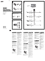
Connection diagram
To a metal surface of the car
First connect the black ground (earth) lead, then connect the
yellow and red power supply leads.
To the power antenna (aerial) control lead or
power supply lead of antenna (aerial) booster
Notes
• It is not necessary to connect this lead if there is no power
antenna (aerial) or antenna (aerial) booster, or with a
manually-operated telescopic antenna (aerial).
• When your car has a built-in FM/MW/SW antenna (aerial)
in the rear/side glass, see “Notes on the control and power
supply leads.”
To the + 12 V power terminal which is
energized in the accessory position of the
ignition switch
Notes
• If there is no accessory position, connect to the + 12 V
power (battery) terminal which is energized at all times.
Be sure to connect the black ground (earth) lead to a
metal surface of the car fi rst.
• When your car has a built-in FM/MW/SW antenna (aerial)
in the rear/side glass, see “Notes on the control and power
supply leads.”
To the + 12 V power terminal which is
energized at all times
Be sure to connect the black ground (earth) lead to a metal
surface of the car fi rst.
Notes on the control and power supply leads
• The power antenna (aerial) control lead (blue) supplies + 12 V
DC when you turn on the tuner.
• When your car has built-in FM/MW/SW antenna (aerial) in the
rear/side glass, connect the power antenna (aerial) control
lead (blue) or the accessory power supply lead (red) to the
power terminal of the existing antenna (aerial) booster. For
details, consult your dealer.
• A power antenna (aerial) without a relay box cannot be used
with this unit.
Memory hold connection
When the yellow power supply lead is connected, power will
always be supplied to the memory circuit even when the ignition
switch is turned off.
Notes on speaker connection
• Before connecting the speakers, turn the unit off.
• Use speakers with an impedance of 4 to 8 ohms, and with
adequate power handling capacities to avoid its damage.
• Do not connect the speaker terminals to the car chassis, or
connect the terminals of the right speakers with those of the
left speaker.
• Do not connect the ground (earth) lead of this unit to the
negative (–) terminal of the speaker.
• Do not attempt to connect the speakers in parallel.
• Connect only passive speakers. Connecting active speakers
(with built-in amplifi ers) to the speaker terminals may damage
the unit.
• To avoid a malfunction, do not use the built-in speaker leads
installed in your car if the unit shares a common negative (–)
lead for the right and left speakers.
• Do not connect the unit’s speaker leads to each other.
Note on connection
If speaker is not connected correctly, “FAILURE” appears in
the display. In this case, make sure the speaker is connected
correctly.
CDX-GT260S
CDX-GT160S
Precauciones
• Esta unidad ha sido diseñada para alimentarse sólo con
cc de 12 V de tierra negativa.
• No coloque los cables debajo de ningún tornillo, ni
los aprisione con partes móviles (p. ej. los raíles del
asiento).
• Antes de realizar las conexiones, desactive el
encendido del automóvil para evitar cortocircuitos.
• Conecte los cables de fuente de alimentación amarillo
y rojo solamente después de haber conectado los
demás.
• Conecte todos los cables de conexión a masa
a un punto común.
• Por razones de seguridad, asegúrese de aislar con cinta
aislante los cables sueltos que no estén conectados.
Notas sobre el cable de fuente de alimentación
(amarillo)
• Cuando conecte esta unidad en combinación con otros
componentes estéreo, la capacidad nominal del circuito
conectado del automóvil debe ser superior a la suma
del fusible de cada componente.
• Si no hay circuitos del automóvil con capacidad
nominal sufi cientemente alta, conecte la unidad
directamente a la batería.
Lista de componentes
• Los números de la lista corresponden a los de las
instrucciones.
• La unidad se comercializa con el soporte y el
marco de protección . Antes de montarla, utilice las
llaves de liberación para extraer el soporte y
el marco de protección de la misma. Para obtener
más información, consulte “Extracción del marco de
protección y del soporte ()”.
• Conserve las llaves de liberación para
utilizarlas en el futuro, ya que también las
necesitará si retira la unidad del automóvil.
Precaución
Tenga mucho cuidado al manipular el soporte para
evitar posibles lesiones en los dedos.
Nota
Antes de instalar la unidad, compruebe que los enganches de
ambos lados del soporte están doblados hacia adentro 2 mm.
Si no lo están o están doblados hacia afuera, la unidad no se
instalará correctamente y puede saltar.
Diagrama de conexión
A una superfi cie metálica del automóvil
Conecte primero el cable de conexión a masa negro, y
después los cables amarillo y rojo de fuente de alimentación.
Al cable de control de la antena motorizada
o al cable de fuente de alimentación del
amplifi cador de señal de la antena
Notas
• Si no se dispone de antena motorizada ni de amplifi cador
de señal de la antena, o se utiliza una antena telescópica
accionada manualmente, no será necesario conectar este
cable.
• Si el automóvil incorpora una antena de FM/MW/SW en el
cristal trasero o lateral, consulte “Notas sobre los cables
de control y de fuente de alimentación”.
Al terminal de alimentación de + 12 V que
recibe energía en la posición de accesorio
del interruptor de la llave de encendido
Notas
• Si no hay posición de accesorio, conéctelo al terminal de
alimentación (batería) de + 12 V que recibe energía sin
interrupción.
Asegúrese de conectar primero el cable de conexión a
masa negro a una superfi cie metálica del automóvil.
• Si el automóvil incorpora una antena de FM/MW/SW en el
cristal trasero o lateral, consulte “Notas sobre los cables
de control y de fuente de alimentación”.
Al terminal de alimentación de + 12 V que
recibe energía sin interrupción
Asegúrese de conectar primero el cable de conexión a masa
negro a una superfi cie metálica del automóvil.
Notas sobre los cables de control y de fuente de
alimentación
• El cable de control de la antena motorizada (azul) suministrará
cc de + 12 V cuando conecte la alimentación del sintonizador.
• Si el automóvil dispone de una antena de FM/MW/SW
incorporada en el cristal trasero o lateral, conecte el cable
de control de antena motorizada (azul) o el cable de fuente
de alimentación auxiliar (rojo) al terminal de alimentación del
amplifi cador de señal de la antena existente. Para obtener más
información, consulte a su distribuidor.
• Con esta unidad no es posible utilizar una antena motorizada
sin caja de relé.
Conexión para protección de la memoria
Si conecta el cable de fuente de alimentación amarillo, el circuito
de la memoria recibirá siempre alimentación, aunque apague el
interruptor de encendido.
Notas sobre la conexión de los altavoces
• Antes de conectar los altavoces, desconecte la alimentación
de la unidad.
• Utilice altavoces con una impedancia de 4 a 8 Ω con la
capacidad de potencia adecuada para evitar que se dañen.
• No conecte los terminales de altavoz al chasis del automóvil,
ni conecte los terminales del altavoz derecho con los del
izquierdo.
• No conecte el cable de conexión a masa de esta unidad al
terminal negativo (–) del altavoz.
• No intente conectar los altavoces en paralelo.
• Conecte solamente altavoces pasivos. Si conecta altavoces
activos (con amplifi cadores incorporados) a los terminales de
altavoz, puede dañar la unidad.
• Para evitar fallos de funcionamiento, no utilice los cables de
altavoz incorporados instalados en el automóvil si su unidad
comparte un cable negativo común (–) para los altavoces
derecho e izquierdo.
• No conecte los cables de altavoz de la unidad entre sí.
Nota sobre la conexión
Si el altavoz no está conectado correctamente, aparecerá
“FAILURE” en la pantalla. Si es así, compruebe la conexión del
altavoz.
Enganche
Equipment used in illustrations (not supplied)
Equipo utilizado en las ilustraciones (no suministrado)
㌶♺ᶑ䗨塁仒濃曂斨彥濄
Fuse (10 A)
Fusible (10 A)
ὁ明䳖!)21!B*
from car antenna (aerial)
desde la antena del automóvil
Ừ兎㯡帮⢍䴾
Left
Izquierdo
ⵊ
Right
Derecho
⍗
Left
Izquierdo
ⵊ
Right
Derecho
⍗
ANT REM
Red
Rojo
䱩凖
Yellow
Amarillo
渧凖
Black
Negro
渵凖
Blue
Azul
唱凖
Max. supply current 0.1 A
Corriente máx. de alimentación de 0,1 A
㙤⢋㷴晟㲥 1/2!B
Rear speaker
Altavoz posterior
⻰㌾俖◌
Front speaker
Altavoz frontal
↱㌾俖◌
Catch
× 2
× 4
㱌び
• 㚐㧃⍎偡ợ䒌射㣙㌉⚔!23!W!䙘㲥晟㷴Ɂ
• ᵱ壥ợ⭲䴾⢢⚌圞㝷ᵯ濇ㅺ䷂㋿⚌䥟∹恌Ṛᵮ
濃⣦濕⸋㡩㇚ㆯᵮ濄Ɂ
• 徇㌉䴾嵓ᶯ↱濇娯敀擭㯡帮湂㿏塁仒ṉ₱峛䝑
嵓Ɂ
• 渧凖⏰䱩凖晟㷴⭲䴾⼩杬⚌ㆤ㙭⃚⫧⭲䴾恡徇㌉⫰
䓆ṉ⻰ㆱ徇㌉Ɂ
• ⭫ㆤ㙭⚔䴾恡徇㌉↔⍰ᵤ㌉⚔湂Ɂ
• 䀞ᷪ⫭濇娯䠞姱㯶㙭徇㌉䗨⭲䴾䒌晟◌億≩
䲒徖垰䲹䵇Ɂ
晟㷴⭲䴾杬䝉濃渧凖濄
• ⭫㚐㧃八⃚⫧䨯樸俖塁仒䲨⍬ợ䒌㖦濇ㆤ徇㌉䗨㯡
帮晟嵓⬝愳⼩杬⢋㔠㬳Ὧ塁仒ὁ明䳖⬝愳䗨䶡⏰Ɂ
• 䓚㯡帮晟嵓⬝愳ᵱ⢄⢋㖦濇娯⭫㚐㧃䙘㌉八晟㯄䙜
徇㌉Ɂ
晚Ṛᵤ夡埌!
• ♺䢞㓜⪻八娎㕲㙜ᶑ䗨㓜⪻㖓ᵤ兘䗨Ɂ
• ㆼ㜚!
!⏰ὁ嫛䐔!
!⚌⅞⹄ᶯ↱ⵖ䳷塁⚌㚐㧃ᵮɁ
⚌⫭塁㚐㧃ᶯ↱濇娯€ợ䒌擯拺揔≽!
!⭫ㆼ㜚!
!
⏰ὁ嫛䐔!
!⼂㚐㧃ᵮ㈪ᵯɁ姗䲔娎㕲濇娯⌧壯㚐
来⌱曆ĥ㈪ᵯὁ嫛䐔⏰ㆼ㜚!)
*ĦɁ
• ⣦㜀Ḯ⻰壥⭫㚐㧃⼂㯡帮ᵮ㈪ᵯ濇᷃壥ợ䒌擯拺揔
≽濇♄㫈娯ὁ⪼⣡擯拺揔≽!
!ṉ´Ḯ⻰ợ䒌Ɂ
㱌び
㉣⌺ㆼ㜚!
!㖦濇娯䇝↉㱌び↉‛↔ㆯ㉫Ɂ
妟
⫭塁ᶯ↱濇⼩杬⭫ㆼ㜚!
!Ῐ䗨㈰懈⍵⺲㙖!3!nnɁ⣦㜀㈰懈
䪪䙘ㅺ⍵⡺⺲㙖濇↫㚐㧃⭫䂅㰹䇆♞⫭塁濇ᶊ⍓偡⺬⅞Ɂ
㈰懈
䴾嵓徇㌉♺!
!徇㌉兗㯡帮䗨愵⯐埌曆
棺€徇㌉渵凖㌉⚔⭲䴾濇䂚⻰徇㌉渧凖⏰䱩凖晟㷴⭲䴾Ɂ
!徇㌉兗晟∹⢍䴾㌋↚⭲䴾ㅺ⢍䴾⊫⠷◌䗨晟㷴⭲
䴾
妟
•!⣦䂅晟∹⢍䴾ㅺ⢍䴾⊫⠷◌濇ㅺ㙭ㆯ∹⢻䬅⢍䴾濇ἣᵱ
杬徇㌉㫈⭲䴾Ɂ
•!「㯡帮䗨⻰濊Ῐ䌟䏧䧻ᶑ⣦㜀㙭!GN0NX0TX!⢍䴾濇⋗
娯⌧䙯ĥ㌋↚䴾⏰晟㷴⭲䴏杬䝉ĦɁ
!
徇㌉兗⚌湂㿏揔≽擯敀䗨斨Ṛằ仒ᵮ彾晟䗨
!
,23!W!
晟㷴䩓⪴
妟
•!剉㯶㙭斨Ṛằ仒濇↫娯徇㌉兗⤯䲦彾晟䗨!,23!W!晟㷴
濃晟㯄濄䩓⪴Ɂ
!⼩杬棺€⭫渵凖㌉⚔⭲䴾徇㌉兗㯡帮䗨愵⯐埌曆Ɂ
•!「㯡帮䗨⻰濊Ῐ䌟䏧䧻ᶑ⣦㜀㙭!GN0NX0TX!⢍䴾濇⋗
娯⌧䙯ĥ㌋↚䴾⏰晟㷴⭲䴏杬䝉ĦɁ
!徇㌉兗⤯䲦彾晟䗨!,23!W!晟㷴䩓⪴
⼩杬棺€⭫渵凖㌉⚔⭲䴾徇㌉兗㯡帮䗨愵⯐埌曆Ɂ
㌋↚䴾⏰晟㷴⭲䴏杬䝉
•!ㆷ擯娣婋◌晟㷴㖦濇晟∹⢍䴾䗨㌋↚⭲䴾濃唱凖濄ἣ偡㌴ỿ!
,23!W!䙘㲥晟Ɂ
•!剉「䗨㯡帮⻰濊Ῐ䌟䏧䧻ᵮ㙭!GN0NX0TX!⢍䴾濇杬⭫晟∹
⢍䴾㌋↚⭲䴾濃唱凖濄ㅺ幸∍晟㷴⭲䴾濃䱩凖濄徇㌉↔䍢㙭⢍
䴾⊫⠷◌ᵮ䗨晟㷴䩓⪴ᵮɁ姗䲔⬝娯⍵戛⒒⒪婒姆Ɂ
•!㚐㧃ᵱ偡ợ䒌ᵱ⃛´䷠晟◌䘶䗨晟∹⢍䴾Ɂ
ὁ㉥奼ㄚ䗨䴾嵓徇㌉㰹
䓚徇㌉⣡渧凖晟㷴⭲䴾㖦濇⋗ợ㯡帮䗠∹㧃湂㿏揔≽敀擭濇晟㷴
ḱ⭫⭱奼ㄚ晟嵓ỿ晟Ɂ
徇㌉㌾俖◌㖦䗨㱌びᷯ杩
•!徇㌉㌾俖◌晟䴾ṉ↱濇娯€敀擭㚐㧃晟㷴Ɂ
•!ợ䒌斟ㇻ䀞!5.9Ã!ᵸ⃛㙭崗⢄∃䋫喹䍪⬝愳䗨㌾俖◌濇ṉ₱㍱
⡂㌾俖◌Ɂ
•!ᵱ壥⭫㌾俖◌䩓⪴徇㌉↔帮帏ᵮ濇ㅺ⭫⍗㌾俖◌䩓⪴八ⵊ㌾俖
◌䩓⪴䙜徇㌉Ɂ
•!Ⅻ≣⭫㚐㧃䗨㌉⚔⭲䴾徇㌉兗㌾俖◌䗨射濃.濄㌉䴾䩓Ɂ
•!㌾俖◌ᵱ⍓ᶊ俓徇㌉Ɂ
•!娯徇㌉䂅㷴㌾俖◌Ɂ剉⭫㙭㷴㌾俖◌濃仒㒢⢋◌濄徇㌉
↔㌾俖◌䩓⪴ᵮ㙧㍱⡂㚐㧃Ɂ
•!剉㚐㧃ợ䒌ⵊɀ⍗㌾俖◌䗨⃕䒌射㣙濃.濄⭲䴾濇䀞ᷪ忣₱㒩
昀濇Ⅻ≣ợ䒌ⵖ⫭塁⚌㯡帮䗨㌾俖◌⭲䴾Ɂ
•!娯≣⭫㚐㧃㌾俖◌⭲䴾䙜᷶徇㌉Ɂ
㙭敀徇㌉㱌びᷯ杩
⣦㜀㚎㫇䠞徇㌉㌾俖◌濇↫染䢞ⶹᵮ㙧⅞䍢ĥGBJMVSFĦɁ㫈㖦濇娯
㫇䠞徇㌉㌾俖◌Ɂ
Connection example
Ejemplo de conexiones
䴾嵓徇㌉♺ữ
White
Blanco
䗡凖
Green
Verde
䴄凖
Purple
Morado
䲏凖
White/black striped
Con rayas blancas y negras
䗡濊渵㠁䱯
Gray/black striped
Con rayas grises y negras
㿔濊渵㠁䱯
Green/black striped
Con rayas verdes y negras
䴄濊渵㠁䱯
Gray
Gris
㿔凖
Purple/black striped
Con rayas moradas y negras
䲏濊渵㠁䱯

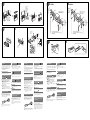
12 3
182 mm
53 mm
A TOYOTA
to dashboard/center console
al tablero o consola central
兗埌㛣濊ᶑ⢒㌋↚䬕
Bracket
Soporte
ㆼ㜚
Bracket
Soporte
ㆼ㜚
B NISSAN
to dashboard/center console
al tablero o consola central
兗埌㛣濊ᶑ⢒㌋↚䬕
Bracket
Soporte
ㆼ㜚
Bracket
Soporte
ㆼ㜚
Existing parts supplied with your car
Piezas existentes suministradas con su automóvil
昌㯡帮斨彥䗨恌Ṛ
AB
12
max. size
5 × 8 mm
(
7
/32 ×
11
/32 in)
Tamaño máx.
5 × 8 mm
㙤⢋⮞⭜
69!nn
max. size
5 × 8 mm
(
7
/32 ×
11
/32 in)
Tamaño máx.
5 × 8 mm
㙤⢋⮞⭜
69!nn
max. size
5 × 8 mm
(
7
/32 ×
11
/32 in)
Tamaño máx.
5 × 8 mm
㙤⢋⮞⭜
69!nn
max. size
5 × 8 mm
(
7
/32 ×
11
/32 in)
Tamaño máx.
5 × 8 mm
㙤⢋⮞⭜
69!nn
Face the hook
inwards.
El gancho debe
encontrarse en la
parte interior.
㋿懈㚁塅曆Ɂ
Claws
Uñas
懈䆎
Mounting example
Installation in the dashboard
Notes
• Bend these claws outward for a tight fi t, if necessary (-
2
).
• Make sure that the 4 catches on the protection collar are
properly engaged in the slots of the unit (-
3
).
Mounting the unit in a Japanese
car
You may not be able to install this unit in some makes of
Japanese cars. In such a case, consult your Sony dealer.
Note
To prevent malfunction, install only with the supplied screws .
How to detach and attach the
front panel
Before installing the unit, detach the front panel.
-A To detach
Before detaching the front panel, be sure to press .
Press
, and pull it off towards you.
-B To attach
Engage part of the front panel with part of the unit,
as illustrated, and push the left side into position until it
clicks.
Warning if your car’s ignition
has no ACC position
Be sure to set the Auto Off function. For details, see the
supplied Operating Instructions.
The unit will shut off completely and automatically in
the set time after the unit is turned off, which prevents
battery drain.
If you do not set the Auto Off function, press and hold
until the display disappears each time you turn
the ignition off.
Precautions
• Choose the installation location carefully so that the
unit will not interfere with normal driving operations.
• Avoid installing the unit in areas subject to dust, dirt,
excessive vibration, or high temperatures, such as in
direct sunlight or near heater ducts.
• Use only the supplied mounting hardware for a safe
and secure installation.
Mounting angle adjustment
Adjust the mounting angle to less than 45°.
Removing the protection collar
and the bracket
Before installing the unit, remove the protection
collar and the bracket from the unit.
1 Remove the protection collar .
Engage the release keys together with the
protection collar
.
Pull out the release keys to remove the
protection collar
.
2 Remove the bracket .
Insert both release keys together between
the unit and the bracket until they click.
Pull down the bracket , then pull up the unit
to separate.
Frequency select switch
The MW (FM) tuning interval is factory-set to the 9 k
(50 k) position. If the frequency allocation system of
your country is based on 10 kHz (200 kHz) interval, set
the switch on the bottom of the unit to the 10 k (200 k)
position before making connections.
Note
If the switch was set with power supplied to the unit, disconnect
the power connector from the unit, wait for 20 seconds, then
reconnect it.
Ejemplo de montaje
Instalación en el tablero
Notas
• Si es necesario, doble estas uñas hacia fuera para que encaje
fi rmemente (-
2
).
• Compruebe que los 4 enganches del marco de protección
estén bien fi jados en las ranuras de la unidad (-
3
).
Montaje de la unidad en un
automóvil japonés
Es posible que no pueda instalar esta unidad en algunos
automóviles japoneses. En tal caso, consulte a su
distribuidor Sony.
Nota
Para evitar que se produzcan fallas, realice la instalación
solamente con los tornillos suministrados .
Forma de extraer e instalar el
panel frontal
Antes de instalar la unidad, extraiga el panel
frontal.
-A Para extraerlo
Antes de extraer el panel frontal, asegúrese de presionar
. Después presione
y tire de él hacia usted.
-B Para instalarlo
Coloque la parte del panel frontal en la parte de
la unidad, como se muestra en la ilustración, y después
presione la parte izquierda hasta que encaje.
Advertencia: si el encendido del
automóvil no dispone de una
posición ACC
Asegúrese de ajustar la función de desconexión
automática. Para obtener más información, consulte el
manual de instrucciones suministrado.
La unidad se apagará completa y automáticamente en
el tiempo establecido después de que se desconecte la
unidad, lo que evita que se desgaste la batería.
Si no ha ajustado la función de desconexión automática,
mantenga presionado cada vez que apague
el interruptor de encendido, hasta que la pantalla
desaparezca.
Precauciones
• Elija cuidadosamente el lugar de montaje de forma que
la unidad no interfi era con las funciones normales de
conducción.
• Evite instalar la unidad donde pueda quedar sometida
a polvo, suciedad, vibraciones excesivas o altas
temperaturas como, por ejemplo, a la luz solar directa o
cerca de conductos de calefacción.
• Para realizar una instalación segura y fi rme, utilice
solamente la ferretería de montaje suministrada.
Ajuste del ángulo de montaje
Ajuste el ángulo de montaje a menos de 45°.
Extracción del marco de
protección y del soporte
Antes de instalar la unidad, retire el marco de
protección y el soporte de la misma.
1 Retire el marco de protección .
Una las llaves de liberación al marco de
protección
.
Retire las llaves de liberación para extraer
el marco de protección
.
2 Retire el soporte .
Inserte ambas llaves de liberación entre la
unidad y el soporte hasta que encajen.
Presione el soporte y, a continuación,
levante la unidad para separar ambos
elementos.
Selector de frecuencia
El intervalo de sintonía de MW (FM) ha sido ajustado
en fábrica a la posición 9 k (50 k). Si el sistema de
asignación de frecuencias de su país se basa en el
intervalo de 10 kHz (200 kHz), ponga este selector,
situado en la base de la unidad, en la posición 10 k
(200 k) antes de realizar las conexiones.
Nota
Si se ajustó el selector con el suministro de alimentación
conectado a la unidad, desconecte el conector de alimentación
de la unidad, espere 20 segundos y, a continuación, vuélvalo a
conectar.
Orient the release key
correctly.
Oriente la llave de
liberación en la
dirección correcta.
㫇䠞⫾ằ擯拺揔≽Ɂ
Existing parts supplied with your car
Piezas existentes suministradas con su automóvil
昌㯡帮斨彥䗨恌Ṛ
ợ䒌↱㱌びᷯ杩
• Ḹ䲔応⌺⫭塁ằ仒濇ṉợ㚐㧃ᵱⷖ㑢㫇䗨椹椿㐱
ỀɁ
• 忣₱⭫㚐㧃⫭塁⚌⌻㿔⟙濇㯅䇍⏰⺛䀬㊓∹⻕杣䗨
⊤❃濇ㅺ⫭塁⚌樼㸏喹濇⣦䙘⭱旡₭ᵯㅺ䄕㮇䬅德
斨張Ɂ
• 䀞ᷪ⫭塁⫭⏰⍓曄濇娯ợ䒌斨彥䗨⫭塁㤯ṚɁ
⫭塁夶⸊ᶯ娣㓘
娯⚌!56ṉ娣㓘⫭塁夶⸊Ɂ
㈪ᵯὁ嫛䐔⏰ㆼ㜚!
⫭塁ᶯ↱濇娯€⼂㚐㧃ᵮ㈪ᵯὁ嫛䐔!
!⏰ㆼ㜚!
Ɂ
1! ㈪ᵯὁ嫛䐔
Ɂ
!⭫擯拺揔≽!
!八ὁ嫛䐔!
!◽⍬Ɂ
!㈭⅞擯拺揔≽!
!ṉ㈪ᵯὁ嫛䐔!
Ɂ
2! ㈪ᵯㆼ㜚
Ɂ
!⭫擯拺揔≽!
!ᵤ峛㌶塁仒⏰ㆼ㜚!
!ᶯ擷濇䙘兗信↔ⓤ┶俖Ɂ
!⍵ᵯ㈭ㆼ㜚!
濇䂚⻰⍵ᵮ㈭塁仒濇ợᶯ䙜
᷶傏晆Ɂ
枟䋫応㐫擯敀
NX濃GN濄娣婋擷旸⚌⅞⹄↱堏妑⫾⚌!:!l濃61!l濄ằ仒
ᵮɁ剉尘♯䗨枟䋫Ⅺ悱䱟䳕㖓❞㔠!21!lI{濃311!lI{濄
擷旸濇徇㌉↱濇娯⭫㚐㧃ⷹ恌ᵮ䗨擯敀妑⫾⚌21l
濃311!l濄ằ仒ᵮɁ
妟
⣦㜀擯敀㖓八晟㷴ᵤ⍰妑仒㔠㚐㧃濇娯⭫晟㷴徇㌉◌⼂㚐㧃㈸旈ṉ
ᶑ㔛徇㌉濇ᶊ䪭ώ31䤶濇愱㔔徇㌉晟㷴徇㌉◌Ɂ
Dashboard
Tablero
埌㛣
Fire wall
Cortafuegos
斖㿏⠥
⫭塁䢞ữ!
⫭塁⚌埌㛣塅
妟!
•!剉㙭⼩壥濇↫⍓⍵⡺⺲㙖彽᷿懈䆎濃.3濄Ɂ
•!⼩杬⭫ὁ嫛䐔!!ᵮ䗨!5!Ὧ㈰懈㫇䠞◽⍬⚌塁仒䗨⋅㥡ᶑ
濃.4濄Ɂ
⭫㚐㧃⫭塁㔠㕉㚐䒆㯡帮ᵮ!
㙭᷿㕉㚐䒆㯡帮ᵱ偡⫭塁㚐㧃濇⚌彽䦒〩⻆ᵯ濇娯⍵!
Tpoz!䳷戛⒪婒姆Ɂ
妟
䀞斖㫆䗠䒃㒩昀濇⫭塁㖦⍎偡ợ䒌斨彥䗨圞䳖!7Ɂ
⣦ẹ㈪⋜⏰塁悱↱曆㛣!
⫭塁㚐㧃ᶯ↱濇娯€㈪⋜↱曆㛣Ɂ
.B!㈪⋜
㈪⋜↱曆㛣ᶯ↱濇杬€㉭ᵯ!!拙Ɂ㉭ᵯ! 濇
ᶊ⻤「兎ⵕ䗨㔝⍵㈭∹佰⌺ᵯ↱曆㛣Ɂ
.C!塁悱
⣦♺䢞⭫↱曆㛣䗨䲨Ṛ!
!八㚐㧃䗨䲨Ṛ!
!䲨塁ᵤ
峛濇ᶊ⭫ⵊῘ㌌⫾ằ䙘↔信↔ⓤ俖䆖㫆Ɂ
⣦㜀「䗨㯡帮㐲㯶㙭!BDD!
ằ仒㖦䗨嫊⎮
娯䠞⫾㖓⎊妑⫾!Bvup!Pgg!∃偡Ɂ剉晤ᷪ奇姗䲔尫
奮濇娯⌧攕昌斨䗨㖓ợ䒌娎㕲㙜Ɂ
㚐㧃㙧⚌妑⫾㖦擷兎∹曆敀㧃濇ṉ忣₱晟䑚佻
晟Ɂ
剉「㚎妑⫾!Bvup!Pgg!∃偡濇娯㉭ẳ!!䙘↔「
㬳㪅䃨㿏㐲䙯↔染䢞㳬⢕䆖㫆Ɂ
-
 1
1
-
 2
2


Sony CDX-GT160S Guía de instalación
- Tipo
- Guía de instalación
- Este manual también es adecuado para
en otros idiomas
- English: Sony CDX-GT160S Installation guide