Yamaha RX-V590RDS Manual de usuario
- Categoría
- Receptor
- Tipo
- Manual de usuario

OWNER’S MANUAL
MODE D’EMPLOI
BEDIENUNGSANLEITUNG
BRUKSANVISNING
MANUALE DI ISTRUZIONI
MANUAL DE INSTRUCCIONES
GEBRUIKSAANWIJZING
Natural Sound Stereo Receiver
Récepteur stéréo “Son Naturel”
Natural Sound Stereoreceiver
Natural Sound Stereoreceiver
Sintonizzatore stereo a suono naturale
Receptor estéreo de Sonido Natural
Natural Sound Stereo Ontvanger
RX-V590RDS

This product complies with the radio frequency interference requirements of the Council Directive 82/499/EEC and/or
87/308/EEC.
Cet appareil est conforme aux prescriptions de la directive communautaire 87/308/CEE.
Diese Geräte entsprechen der EG-Richtlinie 82/499/EWG und/oder 87/308/EWG.
Dette apparat overholder det gaeldende EF-direktiv vedrørende radiostøj.
Questo apparecchio è conforme al D.M.13 aprile 1989 (Direttiva CEE/87/308) sulla soppressione dei radiodisturbi.
Este producto está de acuerdo con los requisitos sobre interferencias de radio frecuencia fijados por el Consejo Directivo
87/308 CEE.
Dit product voldoet aan de EEG normen betreffende radio-frekwentie storingen 82/499/EEG en/of 87/308/EEG.
2
●
Indoor FM Antenna
●
Antenne FM intérieure
●
UKW-Innenantenne
●
FM inomhusantenn
●
Antenna FM per interni
●
Antena FM interior
●
FM Binnenantenne
●
AM Loop Antenna
●
Cadre-antenna AM
●
MW-Rahmenantenne
●
AM ramantenn
●
Antenna AM ad anello
●
Antena de cuadro de AM
●
AM Lusantenne
●
Remote Control Transmitter
●
Emetteur de télécommande
●
Fernbedienungsgeber
●
Fjärrkontrollsändare
●
Telecomando
●
Transmisor del control remoto
●
Afstandbediening
●
Batteries (size AA, R6, UM-3)
●
Piles (taille AA, R6, UM-3)
●
Batterien (Größe AA, R6, UM-3)
●
Batterier (storlek AA, R6, UM-3)
●
Batterie (dimensioni AA, R6, UM-3)
●
Pilas (tamaño AA, R6, UM-3)
●
Batterijen (maat AA, R6, UM-3)
SUPPLIED ACCESSORIES
●
After unpacking, check that the following parts are included.
ACCESSOIRES FOURNIS
●
Après le déballage, vérifier que les pièces suivantes sont incluses.
MITGELIEFERTE ZUBEHORTEILE
●
Nach dem Auspacken überprüfen, ob die folgenden Teile vorhanden sind.
MEDFOLJANDE TILLBEHOR
●
Kontrollera efter det apparaten packats upp att följande delar finns med.
ACCESSORI IN DOTAZIONE
●
Verificare che tutte le parti seguenti siano contenute nell’imballaggio dell’apparecchio.
ACCESORIOS INCLUIDOS
●
Desembale el aparato y verificar que los siguientes accesorios están en la caja.
BIJGELEVERDE ACCESSOIRES
●
Controleer na het uitpakken of de volgende onderdelen voorhanden zijn.

FEATURES
CONTENTS
3
English
●
5 Speaker Configuration
Front: 70W + 70W (8Ω) RMS Output
Power, 0.04% THD, 20–20,000 Hz
Center: 70W (8Ω) RMS Output Power,
0.07% THD, 1 kHz
Rear: 20W + 20W (8Ω) RMS Output
Power, 0.3% THD, 1 kHz
●
Digital Sound Field Processor
6 Programs for Digital Sound Field
Processing
2 Programs for Dolby Surround Decoding
(DOLBY PRO LOGIC and DOLBY PRO
LOGIC ENHANCED)
●
Automatic Input Balance Control for
Dolby Surround
●
Test Tone Generator for Easier Speaker
Output Balance Adjustment
●
3 Center Channel Modes
(NORMAL/WIDE/PHANTOM)
●
Multi-Functions for RDS Broadcast
Reception
●
40-Station Random Access Preset Tuning
●
Automatic Preset Tuning
●
Preset Station Shifting Capability (Preset
Editing)
●
IF Count Direct PLL Synthesizer Tuning
System
●
Video Signal Input/Output Capability
(Including S Video Connections)
●
SLEEP Timer
●
Remote Control Capability
Supplied Accessories ......................................2
Caution ............................................................4
Profile of This Unit ...........................................5
Speaker Setup for This Unit ............................6
Connections ....................................................7
Speaker Balance Adjustment ........................13
Basic Operations ...........................................16
Tuning Operations .........................................19
Preset Tuning ................................................20
Receiving RDS Stations ................................23
Using Digital Sound Field Processor (DSP)
......................................................................27
Setting the SLEEP Timer ..............................31
Remote Control Transmitter ..........................32
Notes about the Remote Control Transmitter
.......................................................................33
Troubleshooting .............................................34
Specifications ................................................35
Thank you for selecting this YAMAHA stereo receiver.

CAUTION : READ THIS BEFORE OPERATING YOUR UNIT.
4
1. To assure the finest performance, please read this manual
carefully. Keep it in a safe place for future reference.
2. Install this unit in a cool, dry, clean place – away from
windows, heat sources, sources of excessive vibration,
dust, moisture and cold. Avoid sources of humming
(transformers, motors). To prevent fire or electrical shock,
do not expose the unit to rain or water.
3. Never open the cabinet. If something drops into the set,
contact your dealer.
4. Do not use force on switches, controls or connection wires.
When moving the unit, first disconnect the power plug and
the wires connected to other equipment. Never pull the
wires themselves.
5. The openings on the cabinet assure proper ventilation of
the unit. If these openings are obstructed, the temperature
inside the cabinet will rise rapidly and eventually damage
the circuits. Therefore, avoid placing objects against these
openings and do not install the unit where the flow of air
through the ventilation openings could be impeded.
6. Always set the VOLUME control to “–
∞
” before starting
the audio source play. Increase the volume gradually to an
appropriate level after playback has been started.
7. Do not attempt to clean the unit with chemical solvents;
this might damage the finish. Use a clean, dry cloth.
8. Be sure to read the “TROUBLESHOOTING” section
regarding common operating errors before concluding that
the unit is faulty.
9. When not planning to use this unit for long periods of time
(ie., vacation, etc.), disconnect the AC power plug from the
wall outlet.
10.To prevent lightning damage, disconnect the AC power
plug and disconnect the antenna cable when there is an
electrical storm.
11.Grounding or polarization – Precautions should be taken
so that the grounding or polarization of an appliance is not
defeated.
12.AC outlet
Do not connect audio equipment to the AC outlet on the
rear panel if that equipment requires more power than the
outlet is rated to provide.
IMPORTANT
Please record the serial number of this unit in the space
below.
Serial No.:
The serial number is located on the rear of the unit.
Retain this Owner’s Manual in a safe place for future
reference.
WARNING
TO REDUCE THE RISK OF FIRE OR ELECTRIC SHOCK,
DO NOT EXPOSE THIS UNIT TO RAIN OR MOISTURE.
For U.K. customers
If the socket outlets in the home are not suitable for the plug
supplied with this appliance, it should be cut off and an
appropriate 3 pin plug fitted. For details, refer to the
instructions described below.
Note: The plug severed from the mains lead must be
destroyed, as a plug with bared flexible cord is hazardous if
engaged in a live socket outlet.
Special Instructions for U.K. Model
IMPORTANT
THE WIRES IN THE MAINS LEAD ARE COLOURED IN
ACCORDANCE WITH THE FOLLOWING CODE:
Blue: NEUTRAL
Brown: LIVE
As the colours of the wires in the main lead of this apparatus
may not correspond with the coloured markings identifying
the terminals in your plug, proceed as follows:
The wire which is coloured BLUE must be connected to the
terminal which is marked with the letter N or coloured
BLACK. The wire which is coloured BROWN must be
connected to the terminal which is marked with the letter L
or coloured RED. Make sure that neither core is connected
to the earth terminal of the three pin plug.
The apparatus is not disconnected from the AC power
source as long as it is connected to the wall outlet, even if
the apparatus itself is turned off.

5
English
PROFILE OF THIS UNIT
You are the proud owner of a Yamaha stereo receiver –an extremely sophisticated audio component. The Digital Sound Field
Processor (DSP) built into this unit takes full advantage of Yamaha’s undisputed leadership in the field of digital audio processing to
bring you a whole new world of listening experiences. Follow the instructions in this manual carefully when setting up your system,
and this unit will sonically transform your room into a wide range of listening environments –movie theater, concert hall, and so on.
In addition, you get incredible realism from Dolby-encoded video sources using the built-in Dolby Pro Logic Surround Decoder.
Please read this operation manual carefully and store it in a safe place for later reference.
Digital Sound Field Processing
What is it that makes live music so good? Today’s advanced
sound reproduction technology lets you get extremely close to
the sound of a live performance, but chances are you’ll still
notice something missing: the acoustic environment of the live
concert hall. Extensive research into the exact nature of the
sonic reflections that create the ambience of a large hall has
made it possible for Yamaha engineers to bring you this same
sound in your own listening room, so you’ll feel all the sound of
a live concert.
What’s more, our technicians, armed with sophisticated
measuring equipment, have even made it possible to capture
the acoustics of a variety of venues such as an actual concert
hall, theater, etc. to allow you to accurately recreate one of
several actual live performance environments, all in your own
home.
Dolby Pro Logic Surround
The Dolby Pro Logic Surround Decoder program lets you
experience the dramatic realism and impact of Dolby Surround
movie theater sound in your own home. Dolby Pro Logic gets
its name from its professional-grade steering logic circuitry,
which provides greater effective front and rear channel
separation for a much higher degree of realism than the
“passive” Dolby Surround circuits found in less sophisticated
home audio/video equipment. Dolby Pro Logic Surround
provides a true center channel, so that there are four
independent channels, unlike passive Dolby Surround which
has in effect only three channels: left, right, and rear. This
center channel allows listeners seated in even less-than-ideal
positions to hear the dialog originating from action on the
screen while getting a stereo effect as well.
This Dolby Pro Logic Surround Decoder employs a digital
signal processing system. This system increases sound
stability at each channel and minimizes crosstalk between
channels compared to conventional analog Dolby signal
processing.
In addition, this unit features a built-in automatic input balance
control. This circuit always presents you the best surround
conditions without performing manual adjustments.
Dolby Pro Logic Surround + DSP
You can also enjoy a combination of Dolby Pro Logic Surround
and DSP in the sound field program “ PRO LOGIC
ENHANCED”.
It recreates the surround effect of a movie theater, effectively
duplicating its multiple surround loudspeaker system,
completely surrounding the listener with the sounds of the
action taking place on the screen.

6
SPEAKER SETUP FOR THIS UNIT
SPEAKERS TO BE USED
This unit is designed to provide the best sound-field quality with a 5 speaker configuration. The speakers to be used with this unit
will be mainly front speakers, rear speakers, and a center speaker. (You can omit the center speaker. Refer to the “4-Speaker
Configuration” shown below.)
The front speakers are used for the main source sound and the effect sound. They will probably be the speakers of your present
stereo speaker system. The rear speakers are used for the effect sound. And the center speaker is used for the center sound
(dialog etc.) encoded with the Dolby Surround. The rear and center speakers do not need to be equal in power to the front
speakers. However, all the speakers should have high enough power handling to accept the maximum output of this unit.
SPEAKER CONFIGURATION
5-Speaker Configuration
This configuration is the most effective and recommended one.
In this configuration, the center speaker is necessary as well as
the rear speakers. If the digital sound field program DOLBY
PRO LOGIC or DOLBY PRO LOGIC ENHANCED is selected,
conversations will be output from the center speaker and the
ambience will be excellent.
●
Set the center channel mode to the “NORMAL” or “WIDE”
position. (For details, refer to page 14.)
4-Speaker Configuration
The center speaker is not used in this configuration. If the
digital sound field program DOLBY PRO LOGIC or DOLBY
PRO LOGIC ENHANCED is selected, the center sound is
output from the left and the right front speakers. However, the
sound effect of other programs can be the same as that of the
5-speaker configuration.
●
Be sure to set the center channel mode to the “PHANTOM”
position. (For details, refer to page 14.)
SPEAKER PLACEMENT
The recommended speaker configuration, the 5-speaker configuration, will require two speaker pairs: front speakers (your normal
stereo speakers), and rear speakers, plus a center speaker. When you place these speakers, refer to the following.
Front: In normal position. (The position of your present
stereo speaker system.)
Rear: Behind your listening position, facing slightly inward.
Nearly six feet (approx. 1.8 m) up from the floor.
Center: Precisely between the front speakers. (To avoid
interference with TV sets, use a magnetically shielded
speaker.)
Front L Center Front R
Dialogue
Surround sound
Dialogue
Surround sound
Rear L
Rear R
Front L Front R
Dialogue
Surround sound
Dialogue
Surround sound
Rear L Rear R
Front R
Center
Front L
TV set
Rear R
Rear L

7
English
CONNECTIONS
Before attempting to make any connections to or from this unit, be sure to first switch OFF the power to this unit and to any other
components to which connections are being made.
CONNECTIONS WITH OTHER COMPONENTS
When making connections between this unit and other components, be sure all connections are made correctly, that is to say L (left)
to L, R (right) to R, “+” to “+” and “–” to “–”. Also, refer to the owner’s manual for each component to be connected to this unit.
:Refer to “ABOUT THE ACCESSORY TERMINALS” on page 11.
GND
MONITOR
OUT
S VIDEO
IN OUT
VCR 2
MONITOR
OUT
LD/TV
IN OUT
VCR 1
IN OUT
VCR 2
PHONO CD TAPE LD/TV VCR 1 VCR 2
TAPE
PB
REC
OUT
IN OUT IN OUT
A OR B:8
Ω
MIN.
/SPEAKER
A B:l6
Ω
MIN.
/SPEAKER
FRONT
C D:4ΩMIN./SPEAKER
SINGLE:8ΩMIN./SPEAKER
8
Ω
MIN.
/SPEAKER
REAR
CENTER
CD
DUAL
SINGLE
FRONT CENTER REAR
SWITCHED
l20W MAX. TOTAL
VIDEO SIGNAL
AUDIO SIGNAL
SPEAKERS
SPEAKERS
OUTPUT
AC OUTLETS
A
B
A
B
l0 dB 0 dB
-
FRONT
LEVEL
FM
ANT
AM
ANT
GND
75
Ω
UNBAL.
fc:200Hz
LOW
PASS
MAINS
OUTPUT
GND
VIDEO IN
AUDIO OUT
VIDEO OUT
VIDEO OUT
AUDIO OUT
VIDEO IN
AUDIO IN
OUTPUT
LINE OUT
LINE IN
VIDEO OUT
AUDIO OUT
AUDIO IN
VIDEO IN
(Europe model)
To AC outlet
Turntable Monitor TV
LD player,
TV tuner, etc. Video cassette recorder 2
CD player Tape deck Video cassette recorder 1

8
CONNECTING TO S VIDEO TERMINALS
If you have a video cassette recorder and a monitor equipped with “S” (high-resolution) video terminals, those terminals can be
connected to this unit’s S VIDEO terminals. Connect the video cassette recorder’s “S” video input and output terminals to this unit’s
S VIDEO VCR 2 IN and OUT terminals respectively, and connect the monitor’s “S” video input terminal to this unit’s S VIDEO
MONITOR OUT terminal. Otherwise, connect the video cassette recorder’s composite video terminals to this unit’s composite video
terminals, and connect the monitor’s composite video input terminal to this unit’s composite MONITOR OUT terminal.
Note
If video signals are sent to both S VIDEO input and composite input terminals, the signals will be sent to their respective
output terminals independently.
CONNECTING TO VIDEO AUX TERMINALS (ON THE FRONT PANEL)
These terminals are used to connect any video input source such as a camcorder to this unit.
MONITOR
OUT
S VIDEO
IN OUT
VCR 2
MONITOR
OUT
LD/TV
IN OUT
VCR 1
IN OUT
VCR 2
VIDEO SIGNAL
S VIDEO
IN
VIDEO
IN
S VIDEO
OUT
S VIDEO
IN
VIDEO OUT
VIDEO IN
Monitor TV
VIDEO AUX
S VIDEO VIDEO L AUDIO R
S VIDEO
L
R
VIDEO
Video cassette recorder 2
Camcorder
AUDIO OUT R
AUDIO OUT L
VIDEO OUT
S VIDEO OUT

9
English
CONNECTING SPEAKERS
A OR B:8
Ω
MIN.
/SPEAKER
A B:l6
Ω
MIN.
/SPEAKER
FRONT
C D:4
Ω
MIN./SPEAKER
SINGLE:8ΩMIN./SPEAKER
8
Ω
MIN.
/SPEAKER
REAR
CENTER
FRONT CENTER REAR
SPEAKERS
SPEAKERS
OUTPUT
A
B
A
B
l0 dB 0 dB
-
FRONT
LEVEL
fc:200Hz
LOW
PASS
CD
DUAL
SINGLE
Connect the respective speakers to this unit as figured below.
Note on front speaker connection:
One or two speaker systems can be connected to this unit. If
you connect only one speaker system, connect it to either the
SPEAKERS A or B terminals.
FRONT LEVEL switch
Normally set to “0 dB”. If desired, you can decrease the
output level at the FRONT SPEAKERS terminals by 10 dB by
setting this switch to “–10 dB”.
Note on center speaker connection:
One or two center speakers can be connected to this unit. If
you cannot place the center speaker on or under the TV, it is
recommended to use two center speakers and place them on
both sides of the TV to orient the center sound at the center
position. For connecting two center speakers, follow the
method shown below.
Rear speakers
Center speaker
FRONT LEVEL
switch
Front speakers B
Left
Right
Left
Right
Center speaker
Center speaker
Front speakers A
Left
Right
l0 dB 0 dB
FRONT
LEVEL
l
REAR
CENTER
CD
DUAL
SINGLE

10
How to Connect:
Connect the SPEAKERS terminals to your speakers with wire
of the proper gauge, cut as short as possible. If the
connections are faulty, no sound will be heard from the
speakers. Make sure that the polarity of the speaker wires is
correct, that is, + and – markings are observed. If these wires
are reversed, the sound will be unnatural and will lack bass.
Do not let the bare speaker wires touch each other and do
not let them touch the metal parts of this unit as this could
damage this unit and/or speakers.
Note
Use speakers with the specified impedance shown on the rear
of this unit.
For connecting to the FRONT SPEAKERS terminals
Red: positive (+)
Black: negative (–)
➀
Unscrew the knob.
➁
Insert the bare wire.
[Remove approx. 5mm
(1/4”) insulation from
the speaker wires.]
➂
Tighten the knob and
secure the wire.
For connecting to the REAR and CENTER SPEAKERS
terminals
Red: positive (+)
Black: negative (–)
➀
Press up the tab.
➁
Insert the bare wire.
[Remove approx. 5mm
(1/4”) insulation from
the speaker wires.]
➂
Release down the tab
and secure the wire.
➁
➂
➀
1
2
3

11
English
Subwoofer system
ABOUT THE ACCESSORY TERMINALS
AC OUTLET(S) (SWITCHED)
(Europe model) ................................. 2 SWITCHED OUTLETS
(U.K. model) ........................................ 1 SWITCHED OUTLET
Use these to connect the power cords from your components
to this unit.
The power to the SWITCHED outlets is controlled by this unit’s
POWER switch or the provided remote control transmitter’s
POWER key. These outlets will supply power to any
component whenever this unit is turned on.
The maximum power (total power consumption of
components) that can be connected to the SWITCHED AC
OUTLET(S) is 120 watts.
GND terminal (For turntable use)
Connecting the ground wire of the turntable to this terminal will
normally minimize hum, but in some cases better results may
be obtained with the ground wire disconnected.
LOW PASS terminal
This terminal is for output to a monaural amplifier driving a
subwoofer. Only frequencies below 200 Hz from the front and
center channels are output.
ADDING A SUBWOOFER
You may wish to add a subwoofer to reinforce the bass
frequencies.
Connect the LOW PASS terminal to the INPUT terminal of
the subwoofer amplifier, and connect the speaker terminals
of the subwoofer amplifier to the subwoofer.
With some subwoofers, including the Yamaha Active Servo
Processing Subwoofer System, the amplifier and subwoofer
are in the same unit.
FRONT OUTPUT terminals
These terminals are for front channel line output. There is no
connection to these terminals when you use the built-in
amplifier.
However, if you drive front speakers with an external stereo
power amplifier, connect the input terminals of the external
amplifier (MAIN IN or AUX terminals of a power amplifier or an
integrated amplifier) to these terminals.
REAR OUTPUT terminals
These terminals are for rear channel line output. There is no
connection to these terminals when you use the built-in
amplifier.
However, if you drive rear speakers with an external stereo
power amplifier, connect the input terminals of the external
amplifier (MAIN IN or AUX terminals of a power amplifier or an
integrated amplifier) to these terminals.
CENTER OUTPUT terminal
This terminal is for center channel line output. There is no
connection to this terminal when you use the built-in amplifier.
However, if you drive a center speaker with an external power
amplifier, connect the input terminal of the external amplifier to
this terminal.
FRONT CENTER REAR
OUTPUT
fc:200Hz
LOW
PASS

12
ANTENNA CONNECTIONS
●
Each antenna should be connected to the designated terminals correctly, referring to the following diagram.
●
Both AM and FM indoor antennas are included with this unit. In general, these antennas will probably provide sufficient signal
strength. Nevertheless, a properly installed outdoor antenna will give clearer reception than an indoor one. If you experience
poor reception quality, an outdoor antenna may result in improvement.
Connecting the AM loop antenna
* The AM loop antenna should be placed apart from the main unit. The antenna may be hung on a wall.
* The AM loop antenna should be kept connected, even if an outdoor AM antenna is connected to this unit.
GND terminal
For maximum safety and minimum interference, connect the
GND terminal to a good earth ground. A good earth ground is
a metal stake driven into moist earth.
Notes
●
When connecting the indoor
FM antenna, insert its
connector into the FM ANT
terminal firmly.
●
If you need an outdoor
FM antenna to improve
FM reception quality, either
300-ohm feeder or coaxial cable may be used. In locations
troubled by electrical interference, coaxial cable is
preferable.
Outdoor FM antenna
Outdoor AM antenna
AM loop
antenna
(included)
Ground
Indoor FM
antenna
(included)
75-ohm/300-ohm
antenna adapter
75-ohm
coaxial cable
300-ohm
feeder
GND
MONITOR
OUT
S VIDEO
IN OUT
VCR 2
PHONO CD
TAPE
PB
FM
ANT
AM
ANT
GND
75
Ω
UNBAL.
➀
➁
➂
Orient so that the best
reception is obtained.
12 3

1
Set to the “
∞
” position.
2 Select the front speakers to be used.
* If you use two front speaker systems, press both the A
and B switches.
3
Set to the “0” position.
4
5 Select the PRO LOGIC or PRO LOGIC
ENHANCED mode, so that the corresponding name is
illuminated on the display.
13
English
SPEAKER BALANCE ADJUSTMENT
This procedure lets you adjust the sound output level balance between the front, center, and rear speakers using the built-in test
tone generator. With this adjustment, the sound output level heard at the listening position will be the same from each speaker.
This is important for the best performance of the digital sound field processor.
The adjustment of each speaker output level should be done at your listening position with the remote control transmitter.
Otherwise, the result may not be satisfactory.
5
1
4
2
3
SPEAKERS
A
B
ON
OFF
ON
OFF
BASS
55
4
3
2
l
0
l
2
3
4
TREBLE
55
4
3
2
l
0
l
2
3
4
BALANCE
55
4
3
2
l
0
l
2
3
4
LR
POWER
TAPE MON
DIR BPLAYDIR A
REC PAUSE
LD/TVSTOPTEST
VCR 1
CNCT VIDEOENHANCED
PRO LOGIC
VCR 2DISCO
STADIUM
MONO MOVIE
CENTER
LEVEL
V AUX
EFFECT
ON/OFF
HALLROCK
VOLUME
REAR
LEVEL
SUR.
DELAY TIME
5
CONTINUED
DISCO
ROCK
CONCERT
CONCERT
HALL
PRO LOGIC
ENHANCED
CONCERT
VIDEO
MONO
MOVIE
STADIUM
DIGITAL SOUND FIELD PROCESSOR
EFFECT

6 Select the center channel output mode according to your
speaker configuration.
(Refer to “SPEAKER CONFIGURATION” on page 6.)
On the feature of each mode, refer to the “Note” shown
below.
7
8 Turn up the volume.
You will hear a test tone (like pink noise) from the left front
speaker, then the center speaker, then the right front
speaker, and then the rear speakers, for about two
seconds each. The display changes as shown below.
* The test tone from the left rear speaker and the right rear
speaker will be heard at the same time.
14
Note
In step 6, when you select the center channel output mode,
note the following.
For 5 speaker configuration)
NORMAL: Select this mode when you use a center speaker
that is smaller than the front speakers. In this
mode, the bass tone will be output from the front
speakers.
WIDE: Select this mode when you use the center speaker
approximately same sized as the front speakers.
For 4 speaker configuration)
PHANTOM: Select this mode when you do not use the center
speaker. The center sound will be output from the
left and right front speakers.
Flashes continuously.
VOLUME
CENTER
MODE
TEST
ER
TEST
NORMAL
WIDE
PHANTOM
TEST
Front (L) Center
Rear
(L and R)
Front (R)
TAPE MON
DIR BPLAYDIR A
REC PAUSE
LD/TVSTOPTEST
VCR 1
CNCT VIDEOENHANCED
PRO LOGIC
VCR 2DISCO
STADIUM
MONO MOVIE
CENTER
LEVEL
V AUX
EFFECT
ON/OFF
HALLROCK
VOLUME
REAR
LEVEL
SUR.
DELAY TIME
7
8
8
6

9 Adjust the BALANCE control so that the effect sound
output level of the left front speaker and the right front
speaker are the same.
10 Adjust the sound output level of the center speaker to
be at the same level as that of the front speakers with
the CENTER LEVEL keys.
11 Adjust the sound output level of the rear speakers to
be at the same level as that of the front speakers with
the REAR LEVEL keys.
12 Cancel the test tone.
Stops flashing and disappears
Notes
●
Once you have completed these adjustments, you can
adjust whole sound level on your audio system by using
the VOLUME control (or the VOLUME keys on the remote
control transmitter).
●
If you use external power amplifiers, their volume controls
may also be adjusted to achieve proper balance.
●
In step 10, if the center channel mode is in the
“PHANTOM” position, the sound output level of the center
speaker cannot be adjusted. This is because in this mode,
the center sound is automatically output from the left and
right front speakers.
●
If there is insufficient sound output from the center and
rear speakers, you may decrease the front speaker output
level by setting the FRONT LEVEL switch on the rear
panel to “–10 dB”.
15
English
BALANCE
55
4
3
2
l
0
l
2
3
4
LR
9
12
10
11
CENTER
LEVEL
00
CENTER
TEST
REAR
LEVEL
0
REAR
TEST
TEST
R
TEST
Lights up.
Adjustable
TAPE MON
DIR BPLAYDIR A
REC PAUSE
LD/TVSTOPTEST
VCR 1
CNCT VIDEOENHANCED
PRO LOGIC
VCR 2DISCO
STADIUM
MONO MOVIE
CENTER
LEVEL
V AUX
EFFECT
ON/OFF
HALLROCK
VOLUME
REAR
LEVEL
SUR.
DELAY TIME
Lights up.
Adjustable

1
Set to the “
∞
” position.
2
3 Select the desired input source by using the input
selector buttons.
(For video sources, turn the TV/monitor ON.)
* The name of the selected input source will appear in
the display.
4 Select the front speakers to be used.
* If you use two front speaker systems, press both the A and
B switches.
5 Play the source. (For detailed information on the
tuning operation, refer to page 19.)
6
Adjust to the desired output level.
7 If desired, adjust the BASS, TREBLE, BALANCE
controls, etc. (refer to page 18) and use the digital
sound field processor. (Refer to page 29.)
Notes on using the input selector buttons
●
Note that pressing on each input selector button selects
the source which is connected to the corresponding input
terminals on the rear panel.
* To select the source connected to the VIDEO AUX
terminals on the front panel, press VIDEO AUX.
●
The selection of TAPE MONITOR cannot be canceled by
pressing another input selector button. To cancel it, press
TAPE MONITOR again.
When you select a button other than TAPE MONITOR,
make sure that TAPE MONITOR is not also selected.
●
If you select the input selector button for a video source
without canceling the selection of TAPE MONITOR, the
playback result will be the video image from the video
source and the sound from the audio tape.
●
Once you play a video source, its video image will not be
interrupted even if the input selector button for an audio
source is selected.
To turn off the power
Press the POWER switch again.
16
BASIC OPERATIONS
TO PLAY A SOURCE
SPEAKERS
A
B
ON
OFF
ON
OFF
VIDEO AUX VCR 2 VCR 1 LD/TV
TAPE
MONITOR
TUNER CD PHONO
3
1, 6
2
4
7
7
POWER

1 Select the source to be recorded.
2
Play the source and then turn the VOLUME control
up to confirm the input source. (For detailed information
on the tuning operations, refer to page 19.)
3 Set the tape deck or VCR to the recording mode.
4 If the tape deck is used for recording, you can monitor
the sounds being recorded by pressing TAPE
MONITOR.
Note
DSP, VOLUME, BASS, TREBLE and BALANCE control
settings have no effect on the material being recorded.
17
English
TO RECORD A SOURCE TO TAPE
(OR DUB FROM TAPE TO TAPE)
VIDEO AUX VCR 2 VCR 1 LD/TV
TAPE
MONITOR
TUNER CD PHONO
VIDEO AUX VCR 2 VCR 1 LD/TV
TAPE
MONITOR
TUNER CD PHONO
1, 4
2

18
Because one or two speaker systems (as front speakers) can
be connected to this unit, the SPEAKERS switches allow you
to select speaker system A or B, or both at once.
Adjust the balance of the output volume to the left and right
speakers to compensate for sound imbalance caused by
speaker location or listening room conditions.
Note
This control is effective only for the sound from the front
speakers.
BASS : Turn this clockwise to increase (or counter-
clockwise to decrease) the low frequency
response.
TREBLE : Turn this clockwise to increase (or counter-
clockwise to decrease) the high frequency
response.
Note
These controls are effective only for the sound from the front
speakers.
When you listen with headphones
Connect the headphones to the PHONES jack. You can listen
to the sound to be output from the front speakers through
headphones.
When listening with headphones privately, set both the
SPEAKERS A and B switches to the OFF position and switch
off the digital sound field processor (so that no DSP program
name is illuminated on the display) by pressing the EFFECT
switch.
Selecting the SPEAKER system
Adjusting the BASS and TREBLE
controls
Adjusting the BALANCE control
PHONES
SPEAKERS
A
B
ON
OFF
ON
OFF
BALANCE
55
4
3
2
l
0
l
2
3
4
LR
TREBLE
55
4
3
2
l
0
l
2
3
4
BASS
55
4
3
2
l
0
l
2
3
4

19
English
1 Select the reception band (FM or AM) while watching
the display.
2
3 Tune to a desired station manually.
* To continue tuning search, press and hold the button.
FM/AM
FM AM
or
1 Select the reception band (FM or AM) while watching
the display.
2
3
To tune to a higher frequency, press the right side once.
To tune to a lower frequency, press the left side once.
* If the station where tuning search stops is not the desired
one, press again.
* If the tuning search does not stop at the desired station
(because the signals of the station are weak), change to
the MANUAL TUNING method.
TUNING OPERATIONS
Normally, if station signals are strong and there is no interference, quick automatic-search tuning (AUTOMATIC TUNING) is
possible. However, if signals of the station you want to select are weak, you must tune to it manually (MANUAL TUNING).
Display information
➀
Displays the band and frequency of the received station.
* If an RDS station is received, the frequency is then
replaced by the station name. (However, if the PS data
cannot be received within 5 seconds, “NO PS” flashes,
and then it returns to the frequency display.)
Refer to page 24 for details.
➁
Lights up when an FM stereo broadcast is received in
stereo.
➂
Indicates the signal level of the received station.
Note
If you tune to an FM station manually, it is received in
monaural mode automatically to increase the signal quality.
AUTOMATIC TUNING MANUAL TUNING
FM/AM
TUNING
MODE
AUTO/MAN’L MONO
TUNING
MODE
AUTO/MAN’L MONO
DOWN
TUNING UP
DOWN
TUNING UP
PRESET
MHz
FM
STEREO
0
20
l00
REAR
➀➁
➂
AUTO TUNING
“AUTO TUNING”
goes off.
FM AM
or
1 3
2

1 Tune to a desired station.
(Refer to the previous page for tuning procedure.)
2 Select a desired page (A – E) of preset station buttons
while watching the display.
3
4 Press a preset station button before “MEMORY”
goes off from the display.
* In the same way, program other stations to A2, A3 ... A8.
* You can program more stations to the preset station
buttons on other pages in the same way by selecting
other pages in step 2.
11 Select the page of preset station buttons.
22 Select the desired preset station button.
Notes
●
A new setting can be programmed in place of the former
one.
●
For presets, the setting of the reception mode (stereo or
monaural) is stored along with the station frequency.
Memory back-up
The memory back-up circuit prevents the programmed data
from being lost even if the POWER switch is set off or the
power plug is disconnected from the AC outlet or the power is
cut due to temporary power failure. If, however, the power is
cut for more than one week, the memory may be erased. If
so, it can be re-programmed by simply following the PRESET
TUNING steps.
20
MANUAL PRESET TUNING
This unit can store station frequencies (selected by tuning operation) by using the preset station buttons. With this function, you can
select any desired station by only pressing the corresponding preset station button. Up to 40 stations (8 stations x 5 pages) can be
stored.
PRESET TUNING
To store stations
To recall a preset station
3
2, 11
4, 22 (Preset station buttons)
A/B/C/D/E
PRESET
MEMORY
MAN’L/AUTO FM
MEMORY
A/B/C/D/E
PRESET
Flashes on and off
for about 5 seconds.
l 2345 67 8
PRESET STATIONS
l 2345 67 8
PRESET STATIONS
PRESET
MHz
FM
STEREO
0
20
l00
REAR
AUTO TUNING
Shows the displayed station has been
programmed to A1.
PRESET

1
2
3
To tune to higher frequencies, press right side once.
To tune to lower frequencies, press left side once.
* If the TUNING button is not pressed, in a while, the
automatic preset tuning begins automatically toward higher
frequencies.
The automatic preset tuning begins from the frequency
currently displayed. Received stations are programmed to
A1, A2 ... A8 sequentially.
* If more than 8 stations are received, they are also
programmed to the preset station numbers on other pages
(B, C, D and E) in that order.
If you want to store the first station received by the
automatic preset tuning to a desired preset station
number.
If, for example, you want to store the first received station to
C5, select “C5” by using the A/B/C/D/E button and the preset
station buttons after pressing the MEMORY button in step 2.
Then press the TUNING button. The first received station is
stored to C5, and next stations to C6, C7 ... sequentially.
If stations are stored up to E8, the automatic preset tuning is
finished automatically.
When the automatic preset tuning is finished
The display shows the frequency of the last preset station.
Check the contents and the number of preset stations by
following the procedure of the section “To recall a preset
station” on page 20.
To recall a preset station
Simply follow the procedure of the section “To recall a preset
station” on page 20.
* A recalled station is shown by the frequency or station name
on the display.
Notes
●
You can replace a preset station by another FM or AM
station manually by simply following the procedure of the
section “To store stations” on page 20.
●
The automatic preset tuning search will be performed
through all RDS network frequencies until stations are
stored up to E8. If the number of received stations is not
enough to be stored up to E8, the search is finished
automatically after searching through all frequencies.
●
With this function, only RDS stations with sufficient signal
strength are stored automatically. If the station you want to
program is weak in signal strength, tune to it in monaural
manually and program it by following the procedure of the
section “To store stations” on page 20.
* There may be a case that this function cannot receive a
station which could be received by the automatic tuning
method. This is because this function receives a large
volume of PI (Program Identification) data along with the
station.
AUTOMATIC PRESET TUNING
You can also make use of an automatic preset tuning function for RDS stations only. By this function, this unit performs automatic
tuning and stores RDS stations with strong signals sequentially. Up to 40 stations are stored automatically in the same way as in
the manual preset tuning method on page 20.
* Refer to page 23–26 for details on RDS stations.
21
English
To store stations
Press and hold for
about 3 seconds.
FM/AM
FM
MEMORY
MAN’L/AUTO FM
PRESET
MEMORY
AUTO TUNING
2
1 3
Flashes.
DOWN
TUNING UP

22
EXCHANGING PRESET STATIONS
You can exchange the places of two preset stations with each other as shown below.
Example)
If you want to shift the preset station on E1 to A5, and vice
versa.
1 Recall the preset station on E1 (by following the method
of “To recall a preset station” on page 20).
2
3 Next, recall the preset station on A5 by following the
same method with step 1.
4
Shows the exchange of stations is completed.
Flashes
Flashes
EDIT
EDIT
MEMORY
MEMORY
2, 4

23
English
RDS (Radio Data System) is a data transmission system gradually being introduced by FM stations in many countries. Stations
using this system transmit an inaudible stream of data in addition to the normal radio signal.
RDS data contains various information, such as AF (Alternative Frequencies for the same program station), PI (Program
Identification), PS (Program Service station name), PTY (Program Type name), etc.
RDS function is carried out among the network stations.
* This unit utilizes PI, PS and PTY to receive RDS broadcast stations.
Displaying RDS data
This unit can be turned into the following two modes to display RDS data.
PS (Program Service station name) mode:
Displays the name of the RDS station now being received instead of the frequency.
PTY (Program Type name) mode:
Displays the program type of the RDS station now being received. There are 15 program types to classify RDS stations as follows.
News:
Short accounts of facts, events and publicly
expressed views, reportage and actuality.
Current affairs:
Topical program expanding or enlarging
upon the news, generally in different
presentation style or concept, including
documentary debate, or analysis
Information:
Program whose purpose is to impart advice
in the widest sense, including meteorological
reports and forecasts, consumer affairs,
medical help, etc.
Sport:
Program concerned with any aspect of sport.
Education:
Program intended primarily to educate, of
which the formal element is fundamental.
Drama:
All radio plays and serials.
Culture:
Programs concerned with any aspect of
national or regional culture, including
religious affairs, philosophy, social science,
language, theatre, etc.
Science:
Programs about the natural sciences and
technology.
Varied:
Used for mainly speech-based programs
usually of light-entertainment nature, not
covered by above categories. Examples are:
quizzes, panel games, personality
interviews, comedy and satire.
Pop:
Commercial music, which would generally be
considered to be of current popular appeal,
often featuring in current or recent record
sales charts.
Rock:
Contemporary modern music, usually written
and performed by young musicians.
M.O.R.:
(Middle of the Road Music). Common term to
describe music considered to be “easy-
listening”, as opposed to Pop, Rock or
Classical. Music in this category is often but
not always, vocal, and usually of short
duration (<5 min.)
Light classics:
Classical Musical for general, rather than
specialist appreciation. Examples of music in
this category are instrumental music, and
vocal or choral works.
Serious classics:
Performances of major orchestral works,
symphonies, chamber music etc., and
including Grand Opera.
Other music:
Musical styles not fitting into any of the
above categories. Particularly used for
specialist music, of which Jazz, Rhythm &
Blues, Folk, Country, and Reggae are
examples.
RECEIVING RDS STATIONS
NEWS
AFFAIRS
INFO
SPORT
EDUCATE
DRAMA
CULTURE
SCIENCE
VARIED
POP M
ROCK M
MOR M
LIGHT M
CLASSICS
OTHER M
BBC R3

24
To turn the unit into the PS mode or PTY mode
Press the FREQ/PS/PTY button. Whenever pressed, the mode changes into the PS mode, PTY mode and returns to usual mode in
turn.
* When an RDS station is received, the display is automatically turned into the PS mode. Do not press the FREQ/PS/PTY button
until the display is turned into the PS mode. If the button is pressed before the display mode is changed, it may occur that “NO
PS” flashes on the display. This is because the unit has not received all of the RDS data on the station yet.
PS mode The name of the station being received is displayed.
If the station is not an RDS station, “NO PS” flashes on the
display and then returns to usual mode.
PTY mode A program type for the station being received is displayed.
If the RDS station does not employ the PTY data service,
“NO PTY” flashes on the display and then returns to the
usual mode.
If the station is not an RDS station, “NO PTY” flashes on the
display and then returns to usual mode.
Usual mode The frequency of the station being received is displayed.
FREQ/PS/PTY
PS/PTY SEEK
Note
When PS or PTY data reception is not possible due to poor reception conditions, “NO PS” or “NO PTY” flashes on the display in
each mode. In such a case, press the TUNING MODE button so that “AUTO TUNING” goes off from the display. Though the
reception mode is changed to monaural by this operation, when you changes to the PS or PTY mode, PS or PTY data may be
displayed.

1
2 Turn the unit into the PS mode.
* If “NO PS” flashes, proceed to the next step while flashing.
If “NO PS” disappears before you proceed to the next step,
press the FREQ/PS/PTY button again.
3
4 Select the first letter or numeral of the station name.
* By pressing the TUNING button repeatedly or by pressing
and holding it, the display will change letters and numerals
in sequence.
* If you will not input the second letter, skip to step 7.
5 When the first letter or numeral of the station name
appears, press the SHIFT button to proceed to the
selection of the next letter or numeral.
6 Repeat steps 4 and 5 for other letters and/or numerals,
if necessary.
7 When inputting the name is finished, press the ENTER
button.
8
The unit begins searching for the station, and it is
continued until the station is found.
You do not have to input a full name for searching
for the station
You may input only the first letter of the station name. If doing
so, you can skip steps 5 and 6. In step 8, the unit searches
for and calls a nearest station which has the letter you input. If
the station is not the desired one, press the TUNING button
again. The unit will begin searching for another station which
has the same letter.
To cancel this function
Press the FREQ/PS/PTY, SHIFT, ENTER, FM/AM or
MEMORY button.
Note
This function is useful especially for calling a station with
weak signals which cannot be received by the automatic
tuning method. By only storing such a station, you can call it
any time easily.
25
English
Calling a preset RDS station by the station name (PS SEEK)
You can call a desired RDS station stored in this unit by only inputting the name of the station in the PS mode. By this operation,
this unit searches all preset stations for the station. You do not have to input a full name, even only the first letter can be used for
calling. As many as 8 letters and/or numerals can be selected for inputting a name.
A station name
is displayed or
“NO PS” flashes.
Flashes.
Flashes.
“A” will flash on the second
letter or numeral position.
Press once.
4, 81
7
2
3, 5
FM
M
FM/AM
FREQ/PS/PTY
PS/PTY SEEK
SHIFT
DOWN
TUNING UP
ENTER
ENTER
SHIFT
DOWN
TUNING UP

26
Calling a preset RDS station by the program type (PTY SEEK)
By designating a program type, the unit automatically searches all preset stations for RDS stations of that program type.
* There are 15 program types to classify RDS stations. For details, refer to page 23.
1 Turn the unit into the PTY mode.
* If “NO PTY” flashes, proceed to the next step while
flashing. If “NO PTY” disappears before you proceed to the
next step, press the FREQ/PS/PTY button once or twice.
2
3 Select the desired program type.
* By pressing the TUNING button repeatedly or by pressing
and holding it, the display will change program types in
sequence.
4 When the desired program type appears, press the
ENTER button.
5
The unit begins searching all preset stations, and calls a
station of the program type if such a station is found.
* When the right side of the TUNING button is pressed, the
search is performed from “A1” toward higher numbers of
the preset stations (A1, A2 ... A8, B1, B2, ...). If, however,
“A3” is currently being called for example, the search
begins from the next station “A4”.
When the left side of the TUNING button is pressed, the
search is performed in reverse order.
If the called station is not the desired one, press the
TUNING button again to search for another station of the
same program type.
To cancel this function
Press the FREQ/PS/PTY, SHIFT, ENTER, FM/AM or
MEMORY button.
Press once or twice until a
program type is displayed
or “NO PTY” flashes.
Flashes.
The program type of the station now being
received or “NEWS” flashes on the display.
Press once.
ENTER
DOWN
TUNING UP
SHIFT
DOWN
TUNING UP
ENTER
3, 5
4
1
2
FREQ/PS/PTY
PS/PTY SEEK

27
English
USING DIGITAL SOUND FIELD PROCESSOR (DSP)
This unit incorporates a sophisticated, multi-program digital sound field processor, which allows you to expand and shape the audio
sound field from both the audio and video sources, for a theater-like experience in the listening/viewing room.
This digital sound field processor has 8 programs; 6 programs for digital sound field processing and 2 programs for the Dolby Pro
Logic Surround sound system (DOLBY PRO LOGIC and DOLBY PRO LOGIC ENHANCED). You can create an excellent audio
sound field by selecting the suitable program and adding desired adjustments. In addition, when the DOLBY PRO LOGIC or
DOLBY PRO LOGIC ENHANCED program is selected, the built-in automatic input balance control functions. This presents you the
best surround condition without manual adjustment.
DELAY TIME CENTER LEVEL REAR LEVEL
CENTER
MODE
DOWN
TUNING UP
DISCO
ROCK
CONCERT
CONCERT
HALL
PRO LOGIC
ENHANCED
CONCERT
VIDEO
MONO
MOVIE
STADIUM
DIGITAL SOUND FIELD PROCESSOR
VIDEO AUX VCR 2 VCR 1 LD/TV
TAPE
MONITOR
TUNER CD PHONO
EFFECT
2345 67 8
PRESET STATIONS
CINEMA DSP
PRESET
kHz
MHz
MEMORY
AM
FM
SLEEP
TAPE MONITOR
STEREO
0
20
l00
ENTER
DELAY
CENTER
REAR
TEST
ms
AUTO TUNING NORMAL WIDEPHANTOM
PRO LOGIC
ENHANCED
CONCERT
VIDEO
MONO
MOVIE
STADIUM
DISCO
ROCK CONCERT
CONCERT HALL
POWER SLEEP PHONO
CDPLAY
PAUSE/STOP
SKIP
DISC
SKIP
TUNER
A/B/C/D/E
PRESET
DECK A/B
TAPE MON
DIR BPLAYDIR A
REC PAUSE
LD/TVSTOPTEST
VCR 1
CNCT VIDEOENHANCED
PRO LOGIC
VCR 2DISCO
STADIUM
MONO MOVIE
CENTER
LEVEL
V AUX
EFFECT
ON/OFF
HALLROCK
VOLUME
REAR
LEVEL
SUR.
DELAY TIME
Front Panel
Remote Control Transmitter
Displays your selection on the
DSP or other informations.
Switches on/off the digital
sound field processor (DSP)
Selects a digital sound field program.
Used for speaker balance adjustment
(For details, refer to page 13, 14 and 15.)
Adjusts sound output
level at each speaker.
(For details, refer to
page 29 and 30.)
Adjusts sound output level at each
speaker.
(For details, refer to page 29 and 30.)
Selects the center channel output
mode. (For details, refer to page 14.)
Adjusts the delay time.
(For details, refer to
page 30.)
Adjusts the delay time.
(For details, refer to
page 30.)
Selects a digital sound
field program.
Switches on/off the
digital sound field
processor (DSP).

28
Description of Each Sound Field Program
The following list gives brief descriptions of the sound fields produced by each of the DSP programs. Keep in mind that most of
these are precise digital recreations of actual acoustic environments. The data for them was recorded at the locations described
using sophisticated sound field measurement equipment.
Note
The channel level balance between the left rear effect speaker and the right rear effect speaker may vary depending on the
sound field you are listening to. This is due to the fact that most of these sound field recreations are actual acoustic
environments.
PROGRAM FEATURE
This program is effective for playback of sources encoded with Dolby Surround.
PRO LOGIC
The employment of the digital signal processing system improves crosstalk and transfers the sound source
more smoothly and precisely, compared to the conventional type. A stable movie sound field is recreated.
This program is effective for playback of sources encoded with Dolby Surround.
PRO LOGIC
Enhancing the “Normal” Dolby Pro Logic, the DSP technology simulates the multi-surround speaker
ENHANCED
systems of a 35 mm film theater, thus widening the surrounded-sound field with greater presence.
CONCERT VIDEO
This program is effective for music videos and gives excellent depth and clarity for vocals. For opera, the
orchestra and stage are ideally recreated, letting you feel as if you were in an actual concert hall.
MONO MOVIE
This program is designed specifically to enhance mono source programs. Compared to a strictly mono
setting, the sound image created in this mode is wider and slightly forward of the speaker pair, lending an
immediacy to the overall sound. It is particularly effective when used with old mono movies, news
broadcasts and dialog.
STADIUM
This program gives you long delays between direct sounds and effect sounds, and extraordinarily
spacious feel of a large stadium.
DISCO
This program recreates the acoustic environment of a lively disco in the heart of a very lively city. The
sound is dense and highly concentrated. It is also characterized by a high-energy, “immediate” sound.
ROCK CONCERT This program is suitable for rock music. A big, powerful sound is reproduced lively and dynamically.
CONCERT HALL
In this program, the center seems deep behind the front speaker pair, creating an expansive, large hall
ambience.
Description of Dolby Pro Logic Surround
DOLBY PRO LOGIC SURROUND: This unit employs
the Dolby Pro Logic Surround system. This system is similar to
professional Dolby Stereo decoders used in movie theaters.
By employing a four-channel system, the Dolby Pro Logic
Surround system divides the input signals into four levels: the
left and right main channels, the center channel (to
characterize dialog), and the rear surround-sound channels (to
characterize sound effects, background noise and other
ambient noise).
Dolby Surround is encoded on the sound track of commercially
available video cassettes and video discs as well. When you
play a source encoded with Dolby Surround on your home
video system, the Dolby Pro Logic Surround system in this unit
decodes the signal and feeds the surround-sound effects.
The Dolby Pro Logic Surround mode may not be always
effective on video sources not encoded with Dolby Surround.
Manufactured under license from Dolby Laboratories Licensing
Corporation. Additionally licensed under Canadian patent
number 1,037,877. “Dolby”, “Pro Logic”, and the double-D
symbol are trademarks of Dolby Laboratories Licensing
Corporation.

1 Follow steps 1 – 6 shown in “BASIC OPERATIONS” on
page 16.
2 Select the desired program that is suitable for the
source.
The selected program name is shown on the display.
3 If desired, adjust the delay time and the output level of
each speaker. (For details, refer to the corresponding
descriptions on this page and the next page.)
Notes
●
If you prefer to cancel the DSP, press the EFFECT switch.
The sound will be the normal 2-channel stereo without
surround sound effect.
●
When CONCERT VIDEO, MONO MOVIE, STADIUM,
DISCO, ROCK CONCERT or CONCERT HALL is
selected, no sound is heard from the center speaker.
●
When a monaural sound source is played with DOLBY
PRO LOGIC or DOLBY PRO LOGIC ENHANCED, no
sound is heard from the front speakers and the rear
speakers. Sound is heard only from the center speaker.
However, if the center channel mode is in PHANTOM, the
front speakers output the sound of the center channel.
●
When this unit’s Dolby Pro Logic Surround system is used,
if the main-source sound is considerably altered by
overadjustment of the BASS or TREBLE controls, the
relationship between the center and rear channels may
produce an unnatural effect.
29
English
To play a source with the digital sound field processor
DISCO
ROCK
CONCERT
CONCERT
HALL
PRO LOGIC
ENHANCED
CONCERT
VIDEO
MONO
MOVIE
STADIUM
DIGITAL SOUND FIELD PROCESSOR
EFFECT
PRO LOGIC
* The following adjustments can be done on the remote control transmitter as well as on the front panel.
If desired, you can adjust the sound output level of the center
speaker even if the output level is already set in “SPEAKER
BALANCE ADJUSTMENT” on page 15.
By continuously pressing “+” or “–” on the CENTER LEVEL
control, the level value changes continuously. However, the
value stops changing momentarily at the preset point (80).
●
If the digital sound field program CONCERT VIDEO, MONO
MOVIE, STADIUM, DISCO, ROCK CONCERT or
CONCERT HALL is selected, the CENTER LEVEL control
cannot function.
●
Once the output level is adjusted, the level value will be the
same in the DOLBY PRO LOGIC and DOLBY PRO LOGIC
ENHANCED programs.
●
If a digital sound field program is not used, the CENTER
LEVEL control will not function.
Adjustment of the CENTER LEVEL
2
3
TAPE MON
DIR BPLAYDIR A
REC PAUSE
LD/TVSTOPTEST
VCR 1
CNCT VIDEOENHANCED
PRO LOGIC
VCR 2DISCO
STADIUM
MONO MOVIE
CENTER
LEVEL
V AUX
EFFECT
ON/OFF
HALLROCK
VOLUME
REAR
LEVEL
SUR.
DELAY TIME
3
2
CENTER LEVEL
CENTER
Lights up.
Adjustable

30
Adjustment of DELAY TIME
You can adjust the time difference between the beginning of
the source sound and the beginning of the effect sound with
the DELAY TIME control.
The DELAY TIME control is effective with all programs.
By applying more or less delay, sound effects, background
noise, and ambient noise coming at you from the rear speakers
can be enhanced or subdued for extra effect.
1. PRO LOGIC : from 15 to 30 milliseconds
(Preset value: 20 milliseconds)
2. PRO LOGIC : from 15 to 30 milliseconds
ENHANCED (Preset value: 20 milliseconds)
3. CONCERT VIDEO : from 1 to 100 milliseconds
(Preset value: 28 milliseconds)
4. MONO MOVIE : from 1 to 100 milliseconds
(Preset value: 20 milliseconds)
5. STADIUM : from 1 to 50 milliseconds
(Preset value: 45 milliseconds)
6. DISCO : from 1 to 100 milliseconds
(Preset value: 14 milliseconds)
7. ROCK CONCERT : from 1 to 100 milliseconds
(Preset value: 17 milliseconds)
8. CONCERT HALL : from 1 to 100 milliseconds
(Preset value: 30 milliseconds)
By continuously pressing “+” or “–” on the DELAY TIME
control, the value changes continuously.
However, the value stops changing momentarily at the preset
point.
Note
Adding too much delay will cause an unnatural effect with
some sources. Experiment with the DELAY TIME control to
create the effect that you find most suitable.
DELAY TIME
STEREO
0
20
l00
DELAY
ms
ONCERT
VIDEO
Adjustable
Adjustment of the REAR LEVEL
If desired, you can adjust the sound output level of the rear
speakers even if the output level is already set in “SPEAKER
BALANCE ADJUSTMENT” on page 15.
By continuously pressing “+” or “–” on the REAR LEVEL
control, the level value changes continuously. However, the
value stops changing momentarily at the preset point (80).
●
Once the output level is adjusted, the level value will be the
same in all the digital sound field programs.
●
If DOLBY PRO LOGIC or a digital sound field program is
not used, the REAR LEVEL control will not function.
Note
The values of the DELAY TIME, CENTER LEVEL and REAR
LEVEL you set the last time will remain memorized even when
the power of this unit is off.
However, if the power cord is kept disconnected for more than
one week, these values will be automatically changed back to
the original factory settings.
REAR LEVEL
REAR
Lights up.
Adjustable

1
Whenever the SLEEP key is pressed, the SLEEP time will
change as follows.
After a while, the display returns to the indication before
the SLEEP timer is set, and the “SLEEP” indicator stops
flashing and lights up.
2 The unit will be turned off automatically at the selected
SLEEP time.
31
English
SETTING THE SLEEP TIMER
If you use the SLEEP timer of this unit, you can make this unit turn off automatically. When you are going to sleep while enjoying a
broadcast or other desired input source, this timer function is helpful.
Notes
●
The SLEEP timer can be controlled only with the remote control transmitter.
●
The components on which the SLEEP timer is effective are the sources connected to the SWITCHED AC OUTLET(S) on the rear
panel of this unit.
To set the SLEEP time
Press once or more to
select the desired
SLEEP time.
Indicates the SLEEP time.
Flashes on and off continuously.
To cancel the selected SLEEP time
Press once or more so that the display returns to the indication
before the SLEEP timer is set. (“SLEEP” will go off from the
display.)
Note
The SLEEP timer setting can also be canceled by turning off
the power with the POWER switch or disconnecting the power
plug of this unit from the AC outlet.
SLEEP
SLEEP
l00
ms
T
SLEEP
120 90 60 30
The SLEEP timer is OFF.
(The indication before the SLEEP
key is pressed.)
(Minutes)

32
REMOTE CONTROL TRANSMITTER
The remote control transmitter provided with this unit is designed to control all the most commonly used functions of the unit. If the
CD player and tape deck connected to this unit are YAMAHA components, then this remote control transmitter will also control
various functions of each component.
KEY FUNCTIONS
For Control of This Unit
For Other Component Control
Identify the remote control transmitter keys with your component’s keys. If these keys are identical, their function will be the
same. On each key function, refer to the corresponding instruction on your component’s manual.
POWER SLEEP PHONO
CDPLAY
PAUSE/STOP
SKIP
DISC
SKIP
TUNER
A/B/C/D/E
PRESET
DECK A/B
TAPE MON
DIR BPLAYDIR A
REC PAUSE
LD/TVSTOPTEST
VCR 1
CNCT VIDEOENHANCED
PRO LOGIC
VCR 2
DISCOSTADIUM
MONO MOVIE
CENTER
LEVEL
V AUX
EFFECT
ON/OFF
HALLROCK
VOLUME
REAR
LEVEL
SUR.
DELAY TIME
POWER SLEEP PHONO
CDPLAY
PAUSE/STOP
SKIP
DISC
SKIP
TUNER
A/B/C/D/E
PRESET
DECK A/B
TAPE MON
DIR BPLAYDIR A
REC PAUSE
LD/TVSTOPTEST
VCR 1
CNCT VIDEOENHANCED
PRO LOGIC
VCR 2DISCO
STADIUM
MONO MOVIE
CENTER
LEVEL
V AUX
EFFECT
ON/OFF
HALLROCK
VOLUME
REAR
LEVEL
SUR.
DELAY TIME
Turns the power on/off.
Selects preset station number.
* +: Selects higher preset
station number.
–: Selects lower preset station
number.
A/B/C/D/E: Selects the page
(A – E) of preset stations.
* Refer to “SETTING THE SLEEP
TIMER” on the previous page.
Controls the tape deck.
* DIR A, B and DECK A/B are
applicable only to a double
cassette tape deck.
* For a single cassette deck with
automatic reverse function,
pressing DIR A will reverse
the direction of tape running.
Controls the compact disc player.
* DISC SKIP is applicable only
to a compact disc changer.
Selects input source.
Turns the master volume level up/down.
* For the DSP control keys, refer to the page 27.

33
English
NOTES ABOUT THE REMOTE CONTROL TRANSMITTER
Battery installation
Battery replacement
If you find that the remote control transmitter must be used
closer to the main unit, the batteries are weak. Replace both
batteries with new ones.
Notes
●
Use only AA, R6, UM-3 batteries for replacement.
●
Be sure the polarities are correct. (See the illustration inside
the battery compartment.)
●
Remove the batteries if the remote control transmitter will
not be used for an extended period of time.
●
If batteries leak, dispose of them immediately. Avoid
touching the leaked material or letting it come in contact with
clothing, etc. Clean the battery compartment thoroughly
before installing new batteries.
Remote control transmitter operation range
Notes
●
There should be no large obstacles between the remote
control transmitter and the main unit.
●
If the remote control sensor is directly illuminated by strong
lighting (especially an inverter type of fluorescent lamp etc.),
it might cause the remote control transmitter not to work
correctly. In this case, reposition the main unit to avoid direct
lighting.
2
1
3
30°
30°
STANDBY mode
While the power is on, pressing the POWER key on the remote
control transmitter switches the unit to the STANDBY mode. (In
this mode, the indicator is half illuminated.)
POWER on mode STANDBY mode
Remote control
sensor
Within approximately
6 m (19.7 feet)

34
AmplifierFMAMOthers
Remote control
transmitter
TROUBLESHOOTING
If the unit fails to operate normally, check the following points to determine whether the fault can be corrected by the simple
measures suggested. If it cannot be corrected, or if the fault is not listed in the SYMPTOM column, disconnect the power cord and
contact your authorized YAMAHA dealer or service center for help.
SYMPTOM
The unit fails to turn on when the POWER
switch is pressed.
No sound or no picture.
The sound suddenly goes off.
Only one side speaker outputs the sound.
Sound “hums”.
The volume level is low while playing a record.
The volume level cannot be increased, or
sound is distorted.
No sound from the rear speakers.
No sound from the center speaker.
FM stereo reception is noisy.
There is distortion and clear reception cannot
be obtained even with a good FM antenna.
A desired station cannot be tuned in with Auto
tuning.
A desired station cannot be tuned in with Auto
tuning.
There are continuous crackling and hissing
noises.
There are buzzing and whining noises
(especially in the evening).
The remote control transmitter does not work.
The sound is degraded when monitoring is
performed by using the headphones connected
to the compact disc player or cassette deck
which are connected with this unit.
CAUSE
Power cord is not plugged in or is not completely
inserted.
Incorrect output cord connections.
Appropriate input selector is not pressed.
The protection circuit has been activated because
of short circuit etc.
The SLEEP timer functioned.
Incorrect setting of the BALANCE control.
Incorrect cord connections.
Incorrect cord connections.
No connection from the turntable to the GND
terminal.
The record is being played on a turntable with an
MC cartridge.
The power to the component connected to the REC
OUT terminals of this unit is off.
The sound output level to the rear speakers is set
to 0.
The monaural sound source is played in DOLBY
PRO LOGIC or DOLBY PRO LOGIC ENHANCED
mode.
The sound output level to the center speaker is set
to 0.
The center channel mode is in PHANTOM mode.
Incorrect sound field program selection.
No sound field program is selected.
Because of the characteristics of FM stereo
broadcasts, this is limited to cases where the
transmitter is too far away or the antenna input is
poor.
There is multipath interference.
The station is too weak.
Weak signal or loose antenna connections.
Noises will result from ligtning, fluorescent lamps,
motors, thermostats and other electrical equipment.
A television set is being used nearby.
Direct sunlight or lighting (of an inverter type of
flourescent lamp etc.) is striking the remote control
sensor of the main unit.
The batteries of this remote control transmitter are
too weak.
The power to this unit is off.
REMEDY
Firmly plug in the power cord.
Connect the cords properly. If the problem persists,
the cords may be defective.
Press the appropriate input selector corresponding
to the input source.
Turning the unit off and then on will reset the
protection circuit.
Do not make the SLEEP timer function.
Adjust it to the appropriate position.
Connect the cords properly. If the problem persists,
the cords may be defective.
Firmly connect the audio plugs. If the problem
persists, the cords may be defective.
Make the GND connection between the turntable
and this unit.
The player should be connected to the unit through
the MC head amplifier.
Turn the power to the component on.
Turn up the sound output level with the REAR
LEVEL control.
Select another program suitable for the monaural
sound source.
Turn up the sound output level with the CENTER
LEVEL control.
Select NORMAL or WIDE.
Select the appropriate program.
Check the antenna connections.
Try using a multiple element FM antenna.
Adjust antenna placement to eliminate multipath
interference.
Use Manual tuning mode.
Use a high quality directional FM antenna.
Tighten the AM loop antenna connections and
rotate it for best reception.
Use Manual tuning mode.
Use an outdoor antenna and a ground wire. This
will help somewhat but it is difficult to eliminate all
noise.
Relocate this unit away from the TV.
Change the position of the main unit.
Replace the batteries with new ones.
Turn the power to this unit on.

35
English
SPECIFICATIONS
AUDIO SECTION
Minimum RMS Output Power per Channel
Front L, R
8 ohms, 20 Hz to 20 kHz, 0.04% THD
...................................................70W+70W
Center
8 ohms, 1 kHz, 0.07% THD
....................70W
Rear L, R
8 ohms, 1 kHz, 0.3% THD............20W+20W
Dynamic Power per Channel
(by IHF Dynamic Headroom measuring
method)
8/6/4/2 ohms.....................95/120/150/170W
DIN Standard Output Power per Channel
4 ohms, 1 kHz, 0.7% THD
[Europe model only] ..........................100W
IEC Power
8 ohms, 1 kHz, 0.1% THD
[Europe model only] ............................78W
Power Band Width
8 ohms, 30W, 0.08% THD
..........................................10 Hz to 50 kHz
Damping Factor (SPEAKERS A)
8 ohms, 20 Hz to 20 kHz .............80 or more
Input Sensitivity/Impedance
PHONO MM.....................2.5 mV/47 k-ohms
CD/TAPE/LD·TV/VCR
......150 mV/47 k-ohms
Maximum Input Signal (1 kHz, 0.5% THD)
PHONO MM......................................115 mV
CD/TAPE/LD·TV/VCR (EFFECT ON)
...............................................................2.2V
Output Level/Impedance
REC OUT.......................150 mV/1.0 k-ohms
PRE OUT
............................2.2V/1.2 k-ohms
LPF (EFFECT OFF)
.............3.5V/1.5 k-ohms
Headphone Jack Rated Output/Impedance
Output Level (8 ohms, 1 kHz, 150 mV)
...............................................................0.5V
Impedance.....................................390 ohms
Frequency Response (20 Hz to 20 kHz)
CD/TAPE/LD·TV/VCR (FRONT L/R)
........................................................0±0.5 dB
RIAA Equalization Deviation
PHONO MM....................................0±0.5 dB
Total Harmonic Distortion
PHONO MM to REC OUT
20 Hz to 20 kHz, 1V..............0.02% or less
CD/TAPE/LD·TV/VCR
to SP OUT
FRONT L/R (EFFECT OFF)
20 Hz to 20 kHz, 30W/8 ohms
...........................................0.02% or less
REAR L/R
1 kHz, 10W/8 ohms..............0.3% or less
Signal-to-Noise Ratio (IHF-A Network)
PHONO MM to REC OUT (5 mV Input
Shorted)..................................82 dB or more
CD/TAPE/LD·TV/VCR
to SP OUT (Input
Shorted, EFFECT OFF) .........99 dB or more
Residual Noise (IHF-A Network)
FRONT L/R............................140 µV or less
Channel Separation
(Vol. –30 dB, EFFECT OFF)
PHONO MM
(Input Shorted, 1 kHz/10 kHz)
.....................60 dB or more/50 dB or more
CD/TAPE/LD·TV/VCR
(Input 5.1 k-ohms Shorted, 1 kHz/10 kHz)
.....................60 dB or more/44 dB or more
Tone Control Characteristics
BASS: Boost/cut................±10 dB (50 Hz)
Turnover Frequency.........(350 Hz)
TREBLE: Boost/cut...........±10 dB (20 kHz)
Turnover Frequency.....(3.5 kHz)
Filter Characteristics
LPF (fc=200 Hz)...............................6 dB/oct
Gain Tracking Error (0 to –60 dB)
...................................................3 dB or less
VIDEO SECTION
Video Signal Level..................1 Vp-p/75 ohms
S-Video Signal Level
Y
...........................................1 Vp-p/75 ohms
C
...................................0.286 Vp-p/75 ohms
Maximum Input Level............1.5 Vp-p or more
Signal-to-Noise Ratio................50 dB or more
Monitor Out Frequency Response
..................................5 Hz to 10 MHz, –3 dB
FM SECTION
Tuning Range.....................87.5 to 108.0 MHz
Usable Sensitivity (75 ohms)
DIN, Mono (S/N 26 dB) ......................0.9 µV
DIN, Stereo (S/N 46 dB) .....................24 µV
Image Response Ratio...........................80 dB
IF Response Ratio..................................80 dB
Spurious Response Ratio.......................70 dB
AM Suppression Ratio............................55 dB
Capture Ratio........................................1.5 dB
Selectivity (two signals, 40 kHz Dev.)
.............................................................70 dB
Signal-to-Noise Ratio
(DIN-Weighted, 40 kHz Dev.)
Mono/Stereo ...........................74 dB/69 dB
Harmonic Distortion (1 kHz, 40 kHz Dev.)
Mono/Stereo ..................................0.1/0.2%
Stereo Separation (1 kHz, 40 kHz Dev.)
.............................................................50 dB
Frequency Response
20 Hz to 15 kHz.............................0 ±1.5 dB
AM SECTION
Tuning Range.......................531 to 1,611 kHz
Usable Sensitivity.............................100 µV/m
Selectivity...............................................32 dB
Signal-to-Noise Ratio .............................50 dB
Image Response Ratio...........................40 dB
Spurious Response Ratio.......................50 dB
Harmonic Distortion (1 kHz) ....................0.3%
AUDIO SECTION
Output Level/Impedance
FM (1 kHz, 40 kHz Dev.)
.......................................400 mV/2.2 k-ohms
AM (30% mod., 1 kHz)
.......................................150 mV/2.2 k-ohms
GENERAL
Power Supply
[U.K. model].........................AC 240V, 50 Hz
[Europe model]....................AC 230V, 50 Hz
Power Consumption...............................300W
AC Outlets
2 SWITCHED OUTLETS
[Europe model] .................120W max. total
1 SWITCHED OUTLET
[U.K. model]......................120W max. total
Dimensions (W x H x D)
........................................435 x 146 x 386 mm
(17-1/8” x 5-3/4” x 15-3/16”)
Weight..............................10 kg (22 lbs. 0 oz.)
Accessories..........................AM loop antenna
Indoor FM antenna
Remote control transmitter
Batteries
Specifications are subject to change without
notice.

YAMAHA ELECTRONICS CORPORATION, USA6660 ORANGETHORPE AVE., BUENA PARK, CALIF. 90620, U.S.A.
YAMAHA CANADA MUSIC LTD.135 MILNER AVE., SCARBOROUGH, ONTARIO M1S 3R1, CANADA
YAMAHA ELECTRONIK EUROPA G.m.b.H.SIEMENSSTR. 22-34, D-25462 RELLINGEN BEI HAMBURG, F.R. OF GERMANY
YAMAHA ELECTRONIQUE FRANCE S.A.RUE AMBROISE CROIZAT BP70 CROISSY-BEAUBOURG 77312 MARNE-LA-VALLEE CEDEX02, FRANCE
YAMAHA ELECTRONICS (UK) LTD.YAMAHA HOUSE, 200 RICKMANSWORTH ROAD WATFORD, HERTS WD1 7JS, ENGLAND
YAMAHA SCANDINAVIA A.B.J A WETTERGRENS GATA 1, BOX 30053, 400 43 VÄSTRA FRÖLUNDA, SWEDEN
YAMAHA MUSIC AUSTRALIA PTY, LTD.17-33 MARKET ST., SOUTH MELBOURNE, 3205 VIC., AUSTRALIA
VT04810
Transcripción de documentos
RX-V590RDS Natural Sound Stereo Receiver Récepteur stéréo “Son Naturel” Natural Sound Stereoreceiver Natural Sound Stereoreceiver Sintonizzatore stereo a suono naturale Receptor estéreo de Sonido Natural Natural Sound Stereo Ontvanger OWNER’S MANUAL MODE D’EMPLOI BEDIENUNGSANLEITUNG BRUKSANVISNING MANUALE DI ISTRUZIONI MANUAL DE INSTRUCCIONES GEBRUIKSAANWIJZING SUPPLIED ACCESSORIES ACCESSOIRES FOURNIS MITGELIEFERTE ZUBEHORTEILE MEDFOLJANDE TILLBEHOR ACCESSORI IN DOTAZIONE ACCESORIOS INCLUIDOS BIJGELEVERDE ACCESSOIRES ● ● ● ● ● ● ● ● ● ● ● ● ● ● ● ● ● ● ● ● ● After unpacking, check that the following parts are included. Après le déballage, vérifier que les pièces suivantes sont incluses. Nach dem Auspacken überprüfen, ob die folgenden Teile vorhanden sind. Kontrollera efter det apparaten packats upp att följande delar finns med. Verificare che tutte le parti seguenti siano contenute nell’imballaggio dell’apparecchio. Desembale el aparato y verificar que los siguientes accesorios están en la caja. Controleer na het uitpakken of de volgende onderdelen voorhanden zijn. Indoor FM Antenna Antenne FM intérieure UKW-Innenantenne FM inomhusantenn Antenna FM per interni Antena FM interior FM Binnenantenne ● AM Loop Antenna Cadre-antenna AM MW-Rahmenantenne AM ramantenn Antenna AM ad anello Antena de cuadro de AM AM Lusantenne ● ● ● ● ● ● ● ● ● ● ● ● ● Remote Control Transmitter Emetteur de télécommande Fernbedienungsgeber Fjärrkontrollsändare Telecomando Transmisor del control remoto Afstandbediening Batteries (size AA, R6, UM-3) Piles (taille AA, R6, UM-3) Batterien (Größe AA, R6, UM-3) Batterier (storlek AA, R6, UM-3) Batterie (dimensioni AA, R6, UM-3) Pilas (tamaño AA, R6, UM-3) Batterijen (maat AA, R6, UM-3) This product complies with the radio frequency interference requirements of the Council Directive 82/499/EEC and/or 87/308/EEC. Cet appareil est conforme aux prescriptions de la directive communautaire 87/308/CEE. Diese Geräte entsprechen der EG-Richtlinie 82/499/EWG und/oder 87/308/EWG. Dette apparat overholder det gaeldende EF-direktiv vedrørende radiostøj. Questo apparecchio è conforme al D.M.13 aprile 1989 (Direttiva CEE/87/308) sulla soppressione dei radiodisturbi. Este producto está de acuerdo con los requisitos sobre interferencias de radio frecuencia fijados por el Consejo Directivo 87/308 CEE. Dit product voldoet aan de EEG normen betreffende radio-frekwentie storingen 82/499/EEG en/of 87/308/EEG. 2 FEATURES ● 5 Speaker Configuration Front: 70W + 70W (8Ω) RMS Output Power, 0.04% THD, 20–20,000 Hz Center: 70W (8Ω) RMS Output Power, 0.07% THD, 1 kHz Rear: 20W + 20W (8Ω) RMS Output Power, 0.3% THD, 1 kHz ● 3 Center Channel Modes (NORMAL/WIDE/PHANTOM) ● Digital Sound Field Processor 6 Programs for Digital Sound Field Processing 2 Programs for Dolby Surround Decoding (DOLBY PRO LOGIC and DOLBY PRO LOGIC ENHANCED) ● Preset Station Shifting Capability (Preset Editing) ● Automatic Input Balance Control for Dolby Surround ● Test Tone Generator for Easier Speaker Output Balance Adjustment English Thank you for selecting this YAMAHA stereo receiver. ● Multi-Functions for RDS Broadcast Reception ● 40-Station Random Access Preset Tuning ● Automatic Preset Tuning ● IF Count Direct PLL Synthesizer Tuning System ● Video Signal Input/Output Capability (Including S Video Connections) ● SLEEP Timer ● Remote Control Capability CONTENTS Supplied Accessories ......................................2 Receiving RDS Stations ................................23 Caution ............................................................4 Using Digital Sound Field Processor (DSP) Profile of This Unit ...........................................5 ......................................................................27 Speaker Setup for This Unit ............................6 Setting the SLEEP Timer ..............................31 Connections ....................................................7 Remote Control Transmitter ..........................32 Speaker Balance Adjustment ........................13 Notes about the Remote Control Transmitter Basic Operations ...........................................16 .......................................................................33 Tuning Operations .........................................19 Troubleshooting .............................................34 Preset Tuning ................................................20 Specifications ................................................35 3 CAUTION : READ THIS BEFORE OPERATING YOUR UNIT. 1. To assure the finest performance, please read this manual carefully. Keep it in a safe place for future reference. 2. Install this unit in a cool, dry, clean place – away from windows, heat sources, sources of excessive vibration, dust, moisture and cold. Avoid sources of humming (transformers, motors). To prevent fire or electrical shock, do not expose the unit to rain or water. For U.K. customers If the socket outlets in the home are not suitable for the plug supplied with this appliance, it should be cut off and an appropriate 3 pin plug fitted. For details, refer to the instructions described below. Note: The plug severed from the mains lead must be destroyed, as a plug with bared flexible cord is hazardous if engaged in a live socket outlet. 3. Never open the cabinet. If something drops into the set, contact your dealer. 4. Do not use force on switches, controls or connection wires. When moving the unit, first disconnect the power plug and the wires connected to other equipment. Never pull the wires themselves. 5. The openings on the cabinet assure proper ventilation of the unit. If these openings are obstructed, the temperature inside the cabinet will rise rapidly and eventually damage the circuits. Therefore, avoid placing objects against these openings and do not install the unit where the flow of air through the ventilation openings could be impeded. 6. Always set the VOLUME control to “– ∞” before starting the audio source play. Increase the volume gradually to an appropriate level after playback has been started. Special Instructions for U.K. Model IMPORTANT THE WIRES IN THE MAINS LEAD ARE COLOURED IN ACCORDANCE WITH THE FOLLOWING CODE: Blue: NEUTRAL Brown: LIVE As the colours of the wires in the main lead of this apparatus may not correspond with the coloured markings identifying the terminals in your plug, proceed as follows: The wire which is coloured BLUE must be connected to the terminal which is marked with the letter N or coloured BLACK. The wire which is coloured BROWN must be connected to the terminal which is marked with the letter L or coloured RED. Make sure that neither core is connected to the earth terminal of the three pin plug. 7. Do not attempt to clean the unit with chemical solvents; this might damage the finish. Use a clean, dry cloth. 8. Be sure to read the “TROUBLESHOOTING” section regarding common operating errors before concluding that the unit is faulty. 9. When not planning to use this unit for long periods of time (ie., vacation, etc.), disconnect the AC power plug from the wall outlet. 10. To prevent lightning damage, disconnect the AC power plug and disconnect the antenna cable when there is an electrical storm. 11. Grounding or polarization – Precautions should be taken so that the grounding or polarization of an appliance is not defeated. 12. AC outlet Do not connect audio equipment to the AC outlet on the rear panel if that equipment requires more power than the outlet is rated to provide. IMPORTANT Please record the serial number of this unit in the space below. Serial No.: The serial number is located on the rear of the unit. Retain this Owner’s Manual in a safe place for future reference. WARNING TO REDUCE THE RISK OF FIRE OR ELECTRIC SHOCK, DO NOT EXPOSE THIS UNIT TO RAIN OR MOISTURE. 4 The apparatus is not disconnected from the AC power source as long as it is connected to the wall outlet, even if the apparatus itself is turned off. You are the proud owner of a Yamaha stereo receiver –an extremely sophisticated audio component. The Digital Sound Field Processor (DSP) built into this unit takes full advantage of Yamaha’s undisputed leadership in the field of digital audio processing to bring you a whole new world of listening experiences. Follow the instructions in this manual carefully when setting up your system, and this unit will sonically transform your room into a wide range of listening environments –movie theater, concert hall, and so on. In addition, you get incredible realism from Dolby-encoded video sources using the built-in Dolby Pro Logic Surround Decoder. Please read this operation manual carefully and store it in a safe place for later reference. English PROFILE OF THIS UNIT Digital Sound Field Processing What is it that makes live music so good? Today’s advanced sound reproduction technology lets you get extremely close to the sound of a live performance, but chances are you’ll still notice something missing: the acoustic environment of the live concert hall. Extensive research into the exact nature of the sonic reflections that create the ambience of a large hall has made it possible for Yamaha engineers to bring you this same sound in your own listening room, so you’ll feel all the sound of a live concert. What’s more, our technicians, armed with sophisticated measuring equipment, have even made it possible to capture the acoustics of a variety of venues such as an actual concert hall, theater, etc. to allow you to accurately recreate one of several actual live performance environments, all in your own home. Dolby Pro Logic Surround The Dolby Pro Logic Surround Decoder program lets you experience the dramatic realism and impact of Dolby Surround movie theater sound in your own home. Dolby Pro Logic gets its name from its professional-grade steering logic circuitry, which provides greater effective front and rear channel separation for a much higher degree of realism than the “passive” Dolby Surround circuits found in less sophisticated home audio/video equipment. Dolby Pro Logic Surround provides a true center channel, so that there are four independent channels, unlike passive Dolby Surround which has in effect only three channels: left, right, and rear. This center channel allows listeners seated in even less-than-ideal positions to hear the dialog originating from action on the screen while getting a stereo effect as well. This Dolby Pro Logic Surround Decoder employs a digital signal processing system. This system increases sound stability at each channel and minimizes crosstalk between channels compared to conventional analog Dolby signal processing. In addition, this unit features a built-in automatic input balance control. This circuit always presents you the best surround conditions without performing manual adjustments. Dolby Pro Logic Surround + DSP You can also enjoy a combination of Dolby Pro Logic Surround and DSP in the sound field program “ PRO LOGIC ENHANCED”. It recreates the surround effect of a movie theater, effectively duplicating its multiple surround loudspeaker system, completely surrounding the listener with the sounds of the action taking place on the screen. 5 SPEAKER SETUP FOR THIS UNIT SPEAKERS TO BE USED This unit is designed to provide the best sound-field quality with a 5 speaker configuration. The speakers to be used with this unit will be mainly front speakers, rear speakers, and a center speaker. (You can omit the center speaker. Refer to the “4-Speaker Configuration” shown below.) The front speakers are used for the main source sound and the effect sound. They will probably be the speakers of your present stereo speaker system. The rear speakers are used for the effect sound. And the center speaker is used for the center sound (dialog etc.) encoded with the Dolby Surround. The rear and center speakers do not need to be equal in power to the front speakers. However, all the speakers should have high enough power handling to accept the maximum output of this unit. SPEAKER CONFIGURATION 5-Speaker Configuration 4-Speaker Configuration This configuration is the most effective and recommended one. In this configuration, the center speaker is necessary as well as the rear speakers. If the digital sound field program DOLBY PRO LOGIC or DOLBY PRO LOGIC ENHANCED is selected, conversations will be output from the center speaker and the ambience will be excellent. ● Set the center channel mode to the “NORMAL” or “WIDE” position. (For details, refer to page 14.) The center speaker is not used in this configuration. If the digital sound field program DOLBY PRO LOGIC or DOLBY PRO LOGIC ENHANCED is selected, the center sound is output from the left and the right front speakers. However, the sound effect of other programs can be the same as that of the 5-speaker configuration. ● Be sure to set the center channel mode to the “PHANTOM” position. (For details, refer to page 14.) Front L Center Front R Front L Dialogue Dialogue Surround sound Surround sound Rear L Rear R Rear L Front R Rear R SPEAKER PLACEMENT The recommended speaker configuration, the 5-speaker configuration, will require two speaker pairs: front speakers (your normal stereo speakers), and rear speakers, plus a center speaker. When you place these speakers, refer to the following. Front: In normal position. (The position of your present stereo speaker system.) Rear: Behind your listening position, facing slightly inward. Nearly six feet (approx. 1.8 m) up from the floor. Center: Precisely between the front speakers. (To avoid interference with TV sets, use a magnetically shielded speaker.) Front R Center Front L TV set Rear R Rear L 6 Before attempting to make any connections to or from this unit, be sure to first switch OFF the power to this unit and to any other components to which connections are being made. English CONNECTIONS CONNECTIONS WITH OTHER COMPONENTS When making connections between this unit and other components, be sure all connections are made correctly, that is to say L (left) to L, R (right) to R, “+” to “+” and “–” to “–”. Also, refer to the owner’s manual for each component to be connected to this unit. LD player, TV tuner, etc. AUDIO IN VIDEO OUT AUDIO OUT VIDEO IN Video cassette recorder 2 VIDEO OUT VIDEO IN AUDIO OUT Monitor TV GND OUTPUT Turntable (Europe model) OUTPUT 8ΩMIN. /SPEAKER FRONT CENTER REAR REAR GND AC OUTLETS SWITCHED l20W MAX. TOTAL 75Ω UNBAL. CENTER FM ANT C D DUAL S VIDEO VCR 2 MONITOR IN OUT OUT GND C D:4ΩMIN./SPEAKER SINGLE:8ΩMIN./SPEAKER VIDEO SIGNAL MONITOR LD/TV OUT VCR 1 IN OUT VCR 2 IN OUT LOW PASS fc:200Hz SINGLE MAINS SPEAKERS SPEAKERS AM ANT A A A OR B:8ΩMIN. /SPEAKER A B:l6ΩMIN. /SPEAKER B PHONO CD TAPE REC PB OUT TAPE IN LD/TV OUT VCR 1 IN B OUT VCR 2 FRONT -l0 dB 0 dB FRONT LEVEL AUDIO SIGNAL CD player Tape deck VIDEO IN AUDIO IN AUDIO OUT VIDEO OUT LINE IN LINE OUT OUTPUT To AC outlet Video cassette recorder 1 : Refer to “ABOUT THE ACCESSORY TERMINALS” on page 11. 7 CONNECTING TO S VIDEO TERMINALS If you have a video cassette recorder and a monitor equipped with “S” (high-resolution) video terminals, those terminals can be connected to this unit’s S VIDEO terminals. Connect the video cassette recorder’s “S” video input and output terminals to this unit’s S VIDEO VCR 2 IN and OUT terminals respectively, and connect the monitor’s “S” video input terminal to this unit’s S VIDEO MONITOR OUT terminal. Otherwise, connect the video cassette recorder’s composite video terminals to this unit’s composite video terminals, and connect the monitor’s composite video input terminal to this unit’s composite MONITOR OUT terminal. Note If video signals are sent to both S VIDEO input and composite input terminals, the signals will be sent to their respective output terminals independently. Monitor TV VIDEO SIGNAL VCR 1 OUT IN VCR 2 OUT VIDEO IN IN VIDEO OUT MONITOR LD/TV OUT S VIDEO IN S VIDEO VCR 2 MONITOR OUT IN OUT S VIDEO OUT S VIDEO IN VIDEO IN Video cassette recorder 2 CONNECTING TO VIDEO AUX TERMINALS (ON THE FRONT PANEL) These terminals are used to connect any video input source such as a camcorder to this unit. VIDEO AUX S VIDEO VIDEO L AUDIO R AUDIO OUT R R AUDIO OUT L L VIDEO OUT VIDEO S VIDEO OUT S VIDEO 8 Camcorder English CONNECTING SPEAKERS Connect the respective speakers to this unit as figured below. Rear speakers Left Right OUTPUT 8ΩMIN. /SPEAKER FRONT CENTER REAR REAR CENTER C D DUAL C D:4ΩMIN./SPEAKER SINGLE:8ΩMIN./SPEAKER LOW PASS fc:200Hz SINGLE SPEAKERS SPEAKERS A A A OR B:8ΩMIN. /SPEAKER A B:l6ΩMIN. /SPEAKER Center speaker B B -l0 dB 0 dB FRONT LEVEL FRONT Left Right FRONT LEVEL switch Front speakers A Left Right Front speakers B Note on front speaker connection: Note on center speaker connection: One or two speaker systems can be connected to this unit. If you connect only one speaker system, connect it to either the SPEAKERS A or B terminals. One or two center speakers can be connected to this unit. If you cannot place the center speaker on or under the TV, it is recommended to use two center speakers and place them on both sides of the TV to orient the center sound at the center position. For connecting two center speakers, follow the method shown below. REAR FRONT LEVEL switch Normally set to “0 dB”. If desired, you can decrease the output level at the FRONT SPEAKERS terminals by 10 dB by setting this switch to “–10 dB”. CENTER C D DUAL SINGLE l l0 dB 0 dB FRONT LEVEL Center speaker Center speaker 9 How to Connect: Connect the SPEAKERS terminals to your speakers with wire of the proper gauge, cut as short as possible. If the connections are faulty, no sound will be heard from the speakers. Make sure that the polarity of the speaker wires is correct, that is, + and – markings are observed. If these wires are reversed, the sound will be unnatural and will lack bass. Do not let the bare speaker wires touch each other and do not let them touch the metal parts of this unit as this could damage this unit and/or speakers. Note Use speakers with the specified impedance shown on the rear of this unit. For connecting to the FRONT SPEAKERS terminals Red: positive (+) Black: negative (–) For connecting to the REAR and CENTER SPEAKERS terminals Red: positive (+) Black: negative (–) ➀ Unscrew the knob. ➁ Insert the bare wire. 2 1 3 [Remove approx. 5mm (1/4”) insulation from the speaker wires.] ➂ Tighten the knob and secure the wire. ➀ Press up the tab. ➁ Insert the bare wire. ➀ ➂ ➁ 10 [Remove approx. 5mm (1/4”) insulation from the speaker wires.] ➂ Release down the tab and secure the wire. English ABOUT THE ACCESSORY TERMINALS AC OUTLET(S) (SWITCHED) FRONT OUTPUT terminals (Europe model) ................................. 2 SWITCHED OUTLETS (U.K. model) ........................................ 1 SWITCHED OUTLET Use these to connect the power cords from your components to this unit. The power to the SWITCHED outlets is controlled by this unit’s POWER switch or the provided remote control transmitter’s POWER key. These outlets will supply power to any component whenever this unit is turned on. The maximum power (total power consumption of components) that can be connected to the SWITCHED AC OUTLET(S) is 120 watts. These terminals are for front channel line output. There is no connection to these terminals when you use the built-in amplifier. However, if you drive front speakers with an external stereo power amplifier, connect the input terminals of the external amplifier (MAIN IN or AUX terminals of a power amplifier or an integrated amplifier) to these terminals. REAR OUTPUT terminals Connecting the ground wire of the turntable to this terminal will normally minimize hum, but in some cases better results may be obtained with the ground wire disconnected. These terminals are for rear channel line output. There is no connection to these terminals when you use the built-in amplifier. However, if you drive rear speakers with an external stereo power amplifier, connect the input terminals of the external amplifier (MAIN IN or AUX terminals of a power amplifier or an integrated amplifier) to these terminals. LOW PASS terminal CENTER OUTPUT terminal This terminal is for output to a monaural amplifier driving a subwoofer. Only frequencies below 200 Hz from the front and center channels are output. This terminal is for center channel line output. There is no connection to this terminal when you use the built-in amplifier. However, if you drive a center speaker with an external power amplifier, connect the input terminal of the external amplifier to this terminal. GND terminal (For turntable use) ADDING A SUBWOOFER You may wish to add a subwoofer to reinforce the bass frequencies. Connect the LOW PASS terminal to the INPUT terminal of the subwoofer amplifier, and connect the speaker terminals of the subwoofer amplifier to the subwoofer. With some subwoofers, including the Yamaha Active Servo Processing Subwoofer System, the amplifier and subwoofer are in the same unit. OUTPUT FRONT CENTER REAR LOW PASS fc:200Hz Subwoofer system 11 ANTENNA CONNECTIONS ● ● Each antenna should be connected to the designated terminals correctly, referring to the following diagram. Both AM and FM indoor antennas are included with this unit. In general, these antennas will probably provide sufficient signal strength. Nevertheless, a properly installed outdoor antenna will give clearer reception than an indoor one. If you experience poor reception quality, an outdoor antenna may result in improvement. Outdoor FM antenna Outdoor AM antenna Indoor FM antenna (included) AM loop antenna (included) GND 75Ω UNBAL. FM ANT 300-ohm feeder S VIDEO VCR 2 MONITOR OUT IN OUT GND AM ANT TAPE PB PHONO 75-ohm coaxial cable CD 75-ohm/300-ohm antenna adapter Ground Connecting the AM loop antenna 1 2 ➀ ➂ ➁ 3 Orient so that the best reception is obtained. * The AM loop antenna should be placed apart from the main unit. The antenna may be hung on a wall. * The AM loop antenna should be kept connected, even if an outdoor AM antenna is connected to this unit. GND terminal For maximum safety and minimum interference, connect the GND terminal to a good earth ground. A good earth ground is a metal stake driven into moist earth. 12 Notes ● When connecting the indoor FM antenna, insert its connector into the FM ANT terminal firmly. ● If you need an outdoor FM antenna to improve FM reception quality, either 300-ohm feeder or coaxial cable may be used. In locations troubled by electrical interference, coaxial cable is preferable. This procedure lets you adjust the sound output level balance between the front, center, and rear speakers using the built-in test tone generator. With this adjustment, the sound output level heard at the listening position will be the same from each speaker. This is important for the best performance of the digital sound field processor. The adjustment of each speaker output level should be done at your listening position with the remote control transmitter. Otherwise, the result may not be satisfactory. 1 5 4 REC PAUSE DIR A PLAY TEST PRO LOGIC CENTER LEVEL TAPE MON LD/TV ENHANCED CNCT VIDEO 5 VCR 1 SUR. MONO MOVIE STADIUM ROCK REAR LEVEL HALL DELAY TIME DISCO VCR 2 EFFECT ON/OFF V AUX VOLUME 3 2 1 4 5 Set to the “ ∞ ” position. 2 DIR B STOP English SPEAKER BALANCE ADJUSTMENT POWER Select the PRO LOGIC or PRO LOGIC ENHANCED mode, so that the corresponding name is illuminated on the display. Select the front speakers to be used. DIGITAL SOUND FIELD PROCESSOR SPEAKERS A B ON ON PRO LOGIC ENHANCED DISCO OFF CONCERT VIDEO ROCK CONCERT CONCERT HALL MONO MOVIE STADIUM EFFECT OFF * If you use two front speaker systems, press both the A and B switches. CONTINUED 3 BASS l 0 TREBLE l 2 l 2 3 3 4 4 5 5 0 BALANCE l 2 l 2 3 3 4 4 5 5 0 l 2 2 3 3 4 4 L 5 5 R Set to the “0” position. 13 REC PAUSE 8 6 DIR A TEST 7 PRO LOGIC CENTER LEVEL DIR B TAPE MON LD/TV ENHANCED CNCT VIDEO VCR 1 SUR. MONO MOVIE STADIUM ROCK REAR LEVEL PLAY STOP HALL DELAY TIME DISCO VCR 2 EFFECT ON/OFF V AUX VOLUME 8 6 Select the center channel output mode according to your speaker configuration. (Refer to “SPEAKER CONFIGURATION” on page 6.) CENTER MODE 7 TEST TEST ER Flashes continuously. NORMAL WIDE 8 Turn up the volume. PHANTOM VOLUME On the feature of each mode, refer to the “Note” shown below. Note In step 6, when you select the center channel output mode, note the following. For 5 speaker configuration) NORMAL: Select this mode when you use a center speaker that is smaller than the front speakers. In this mode, the bass tone will be output from the front speakers. WIDE: Select this mode when you use the center speaker approximately same sized as the front speakers. You will hear a test tone (like pink noise) from the left front speaker, then the center speaker, then the right front speaker, and then the rear speakers, for about two seconds each. The display changes as shown below. Front (L) Center TEST For 4 speaker configuration) PHANTOM: Select this mode when you do not use the center speaker. The center sound will be output from the left and right front speakers. Rear (L and R) Front (R) * The test tone from the left rear speaker and the right rear speaker will be heard at the same time. 14 English REC PAUSE 12 10 11 DIR A TEST PRO LOGIC CENTER LEVEL DIR B TAPE MON LD/TV ENHANCED CNCT VIDEO VCR 1 SUR. MONO MOVIE STADIUM ROCK REAR LEVEL PLAY STOP HALL DELAY TIME DISCO VCR 2 EFFECT ON/OFF V AUX VOLUME 9 9 12 Adjust the BALANCE control so that the effect sound output level of the left front speaker and the right front speaker are the same. Cancel the test tone. TEST TEST R BALANCE l 0 l 2 2 3 3 4 L 5 10 Stops flashing and disappears 4 5 R Adjust the sound output level of the center speaker to be at the same level as that of the front speakers with the CENTER LEVEL keys. Lights up. TEST CENTER LEVEL CENTER 00 Adjustable 11 Notes Once you have completed these adjustments, you can adjust whole sound level on your audio system by using the VOLUME control (or the VOLUME keys on the remote control transmitter). ● If you use external power amplifiers, their volume controls may also be adjusted to achieve proper balance. ● In step 10, if the center channel mode is in the “PHANTOM” position, the sound output level of the center speaker cannot be adjusted. This is because in this mode, the center sound is automatically output from the left and right front speakers. ● If there is insufficient sound output from the center and rear speakers, you may decrease the front speaker output level by setting the FRONT LEVEL switch on the rear panel to “–10 dB”. ● Adjust the sound output level of the rear speakers to be at the same level as that of the front speakers with the REAR LEVEL keys. Lights up. TEST REAR LEVEL 0 REAR Adjustable 15 BASIC OPERATIONS 1, 6 3 2 4 7 7 TO PLAY A SOURCE 1 5 Play the source. (For detailed information on the tuning operation, refer to page 19.) 6 Set to the “ ∞ ” position. 2 POWER Adjust to the desired output level. 7 3 Select the desired input source by using the input selector buttons. (For video sources, turn the TV/monitor ON.) TAPE MONITOR TUNER CD PHONO VIDEO AUX VCR 2 VCR 1 LD/TV * The name of the selected input source will appear in the display. 4 Select the front speakers to be used. SPEAKERS A B ON ON OFF OFF If desired, adjust the BASS, TREBLE, BALANCE controls, etc. (refer to page 18) and use the digital sound field processor. (Refer to page 29.) Notes on using the input selector buttons Note that pressing on each input selector button selects the source which is connected to the corresponding input terminals on the rear panel. * To select the source connected to the VIDEO AUX terminals on the front panel, press VIDEO AUX. ● The selection of TAPE MONITOR cannot be canceled by pressing another input selector button. To cancel it, press TAPE MONITOR again. When you select a button other than TAPE MONITOR, make sure that TAPE MONITOR is not also selected. ● If you select the input selector button for a video source without canceling the selection of TAPE MONITOR, the playback result will be the video image from the video source and the sound from the audio tape. ● Once you play a video source, its video image will not be interrupted even if the input selector button for an audio source is selected. ● To turn off the power Press the POWER switch again. * If you use two front speaker systems, press both the A and B switches. 16 2 English 1, 4 TO RECORD A SOURCE TO TAPE (OR DUB FROM TAPE TO TAPE) 1 2 3 4 Note DSP, VOLUME, BASS, TREBLE and BALANCE control settings have no effect on the material being recorded. Select the source to be recorded. TAPE MONITOR TUNER CD PHONO VIDEO AUX VCR 2 VCR 1 LD/TV Play the source and then turn the VOLUME control up to confirm the input source. (For detailed information on the tuning operations, refer to page 19.) Set the tape deck or VCR to the recording mode. If the tape deck is used for recording, you can monitor the sounds being recorded by pressing TAPE MONITOR. TAPE MONITOR TUNER CD PHONO VIDEO AUX VCR 2 VCR 1 LD/TV 17 Selecting the SPEAKER system Because one or two speaker systems (as front speakers) can be connected to this unit, the SPEAKERS switches allow you to select speaker system A or B, or both at once. Adjusting the BASS and TREBLE controls BASS l 0 TREBLE l 2 SPEAKERS A B ON ON OFF OFF 3 l 2 3 4 5 0 2 3 4 BASS l 2 3 4 5 4 5 5 : Turn this clockwise to increase (or counterclockwise to decrease) the low frequency response. Adjusting the BALANCE control Adjust the balance of the output volume to the left and right speakers to compensate for sound imbalance caused by speaker location or listening room conditions. BALANCE l 0 l 2 2 3 TREBLE : Turn this clockwise to increase (or counterclockwise to decrease) the high frequency response. Note These controls are effective only for the sound from the front speakers. 3 4 4 L 5 5 R Note This control is effective only for the sound from the front speakers. When you listen with headphones Connect the headphones to the PHONES jack. You can listen to the sound to be output from the front speakers through headphones. When listening with headphones privately, set both the SPEAKERS A and B switches to the OFF position and switch off the digital sound field processor (so that no DSP program name is illuminated on the display) by pressing the EFFECT switch. 18 PHONES Normally, if station signals are strong and there is no interference, quick automatic-search tuning (AUTOMATIC TUNING) is possible. However, if signals of the station you want to select are weak, you must tune to it manually (MANUAL TUNING). English TUNING OPERATIONS 2 1 3 AUTOMATIC TUNING 1 MANUAL TUNING Select the reception band (FM or AM) while watching the display. 1 FM/AM FM/AM or FM 2 Select the reception band (FM or AM) while watching the display. AM FM 2 TUNING MODE “AUTO TUNING” goes off. AUTO/MAN’L MONO 3 DOWN TUNING 3 UP Tune to a desired station manually. DOWN To tune to a higher frequency, press the right side once. To tune to a lower frequency, press the left side once. * If the station where tuning search stops is not the desired one, press again. * If the tuning search does not stop at the desired station (because the signals of the station are weak), change to the MANUAL TUNING method. AM TUNING MODE AUTO TUNING AUTO/MAN’L MONO or TUNING UP * To continue tuning search, press and hold the button. Note If you tune to an FM station manually, it is received in monaural mode automatically to increase the signal quality. Display information ➀ ➀ ➁ STEREO PRESET FM MHz 0 20 l00 REAR ➁ ➂ Displays the band and frequency of the received station. * If an RDS station is received, the frequency is then replaced by the station name. (However, if the PS data cannot be received within 5 seconds, “NO PS” flashes, and then it returns to the frequency display.) Refer to page 24 for details. Lights up when an FM stereo broadcast is received in stereo. Indicates the signal level of the received station. ➂ 19 PRESET TUNING MANUAL PRESET TUNING This unit can store station frequencies (selected by tuning operation) by using the preset station buttons. With this function, you can select any desired station by only pressing the corresponding preset station button. Up to 40 stations (8 stations x 5 pages) can be stored. 2, 1 4, 2 (Preset station buttons) 3 To recall a preset station To store stations 1 Tune to a desired station. (Refer to the previous page for tuning procedure.) 1 Select the page of preset station buttons. A/B/C/D/E 2 PRESET Select a desired page (A – E) of preset station buttons while watching the display. A/B/C/D/E PRESET 2 Select the desired preset station button. l 2 3 PRESET STATIONS 4 5 6 7 8 3 MEMORY MEMORY MAN’L/AUTO FM Flashes on and off for about 5 seconds. 4 Press a preset station button before “MEMORY” goes off from the display. l 2 3 PRESET STATIONS 4 5 6 7 8 STEREO PRESET FM MHz 0 20 l00 REAR AUTO TUNING Shows the displayed station has been programmed to A1. * * 20 PRESET In the same way, program other stations to A2, A3 ... A8. You can program more stations to the preset station buttons on other pages in the same way by selecting other pages in step 2. Notes ● A new setting can be programmed in place of the former one. ● For presets, the setting of the reception mode (stereo or monaural) is stored along with the station frequency. Memory back-up The memory back-up circuit prevents the programmed data from being lost even if the POWER switch is set off or the power plug is disconnected from the AC outlet or the power is cut due to temporary power failure. If, however, the power is cut for more than one week, the memory may be erased. If so, it can be re-programmed by simply following the PRESET TUNING steps. You can also make use of an automatic preset tuning function for RDS stations only. By this function, this unit performs automatic tuning and stores RDS stations with strong signals sequentially. Up to 40 stations are stored automatically in the same way as in the manual preset tuning method on page 20. * Refer to page 23–26 for details on RDS stations. English AUTOMATIC PRESET TUNING 2 13 To store stations 1 When the automatic preset tuning is finished FM/AM FM The display shows the frequency of the last preset station. Check the contents and the number of preset stations by following the procedure of the section “To recall a preset station” on page 20. To recall a preset station 2 MEMORY PRESET MAN’L/AUTO FM Simply follow the procedure of the section “To recall a preset station” on page 20. * A recalled station is shown by the frequency or station name on the display. MEMORY AUTO TUNING Press and hold for about 3 seconds. 3 DOWN Flashes. TUNING UP To tune to higher frequencies, press right side once. To tune to lower frequencies, press left side once. * If the TUNING button is not pressed, in a while, the automatic preset tuning begins automatically toward higher frequencies. The automatic preset tuning begins from the frequency currently displayed. Received stations are programmed to A1, A2 ... A8 sequentially. * If more than 8 stations are received, they are also programmed to the preset station numbers on other pages (B, C, D and E) in that order. Notes ● You can replace a preset station by another FM or AM station manually by simply following the procedure of the section “To store stations” on page 20. ● The automatic preset tuning search will be performed through all RDS network frequencies until stations are stored up to E8. If the number of received stations is not enough to be stored up to E8, the search is finished automatically after searching through all frequencies. ● With this function, only RDS stations with sufficient signal strength are stored automatically. If the station you want to program is weak in signal strength, tune to it in monaural manually and program it by following the procedure of the section “To store stations” on page 20. * There may be a case that this function cannot receive a station which could be received by the automatic tuning method. This is because this function receives a large volume of PI (Program Identification) data along with the station. If you want to store the first station received by the automatic preset tuning to a desired preset station number. If, for example, you want to store the first received station to C5, select “C5” by using the A/B/C/D/E button and the preset station buttons after pressing the MEMORY button in step 2. Then press the TUNING button. The first received station is stored to C5, and next stations to C6, C7 ... sequentially. If stations are stored up to E8, the automatic preset tuning is finished automatically. 21 EXCHANGING PRESET STATIONS You can exchange the places of two preset stations with each other as shown below. 2, 4 Example) If you want to shift the preset station on E1 to A5, and vice versa. 1 2 Recall the preset station on E1 (by following the method of “To recall a preset station” on page 20). 4 EDIT EDIT MEMORY Flashes 3 Next, recall the preset station on A5 by following the same method with step 1. Shows the exchange of stations is completed. MEMORY Flashes 22 RDS (Radio Data System) is a data transmission system gradually being introduced by FM stations in many countries. Stations using this system transmit an inaudible stream of data in addition to the normal radio signal. RDS data contains various information, such as AF (Alternative Frequencies for the same program station), PI (Program Identification), PS (Program Service station name), PTY (Program Type name), etc. RDS function is carried out among the network stations. * This unit utilizes PI, PS and PTY to receive RDS broadcast stations. English RECEIVING RDS STATIONS Displaying RDS data This unit can be turned into the following two modes to display RDS data. PS (Program Service station name) mode: Displays the name of the RDS station now being received instead of the frequency. BBC R3 PTY (Program Type name) mode: Displays the program type of the RDS station now being received. There are 15 program types to classify RDS stations as follows. NEWS News: Short accounts of facts, events and publicly expressed views, reportage and actuality. AFFAIRS INFO VARIED Current affairs: Topical program expanding or enlarging upon the news, generally in different presentation style or concept, including documentary debate, or analysis Varied: Used for mainly speech-based programs usually of light-entertainment nature, not covered by above categories. Examples are: quizzes, panel games, personality interviews, comedy and satire. POP M Information: Program whose purpose is to impart advice in the widest sense, including meteorological reports and forecasts, consumer affairs, medical help, etc. Pop: Commercial music, which would generally be considered to be of current popular appeal, often featuring in current or recent record sales charts. ROCK M Rock: Contemporary modern music, usually written and performed by young musicians. MOR M M.O.R.: (Middle of the Road Music). Common term to describe music considered to be “easylistening”, as opposed to Pop, Rock or Classical. Music in this category is often but not always, vocal, and usually of short duration (<5 min.) LIGHT M Light classics: Classical Musical for general, rather than specialist appreciation. Examples of music in this category are instrumental music, and vocal or choral works. SPORT Sport: Program concerned with any aspect of sport. EDUCATE Education: Program intended primarily to educate, of which the formal element is fundamental. DRAMA Drama: All radio plays and serials. CULTURE Culture: Programs concerned with any aspect of national or regional culture, including religious affairs, philosophy, social science, language, theatre, etc. SCIENCE Science: Programs about the natural sciences and technology. classics: CLASSICS Serious Performances of major orchestral works, symphonies, chamber music etc., and including Grand Opera. OTHER M Other music: Musical styles not fitting into any of the above categories. Particularly used for specialist music, of which Jazz, Rhythm & Blues, Folk, Country, and Reggae are examples. 23 To turn the unit into the PS mode or PTY mode Press the FREQ/PS/PTY button. Whenever pressed, the mode changes into the PS mode, PTY mode and returns to usual mode in turn. * When an RDS station is received, the display is automatically turned into the PS mode. Do not press the FREQ/PS/PTY button until the display is turned into the PS mode. If the button is pressed before the display mode is changed, it may occur that “NO PS” flashes on the display. This is because the unit has not received all of the RDS data on the station yet. PS mode The name of the station being received is displayed. If the station is not an RDS station, “NO PS” flashes on the display and then returns to usual mode. PTY mode A program type for the station being received is displayed. If the RDS station does not employ the PTY data service, “NO PTY” flashes on the display and then returns to the usual mode. If the station is not an RDS station, “NO PTY” flashes on the display and then returns to usual mode. Usual mode The frequency of the station being received is displayed. PS/PTY SEEK FREQ/PS/PTY Note When PS or PTY data reception is not possible due to poor reception conditions, “NO PS” or “NO PTY” flashes on the display in each mode. In such a case, press the TUNING MODE button so that “AUTO TUNING” goes off from the display. Though the reception mode is changed to monaural by this operation, when you changes to the PS or PTY mode, PS or PTY data may be displayed. 24 English Calling a preset RDS station by the station name (PS SEEK) You can call a desired RDS station stored in this unit by only inputting the name of the station in the PS mode. By this operation, this unit searches all preset stations for the station. You do not have to input a full name, even only the first letter can be used for calling. As many as 8 letters and/or numerals can be selected for inputting a name. 2 3, 5 7 1 4, 8 FM/AM 1 2 FM 6 7 Turn the unit into the PS mode. PS/PTY SEEK A station name is displayed or “NO PS” flashes. FREQ/PS/PTY Repeat steps 4 and 5 for other letters and/or numerals, if necessary. When inputting the name is finished, press the ENTER button. ENTER ENTER * If “NO PS” flashes, proceed to the next step while flashing. If “NO PS” disappears before you proceed to the next step, press the FREQ/PS/PTY button again. 3 8 DOWN TUNING UP Press once. SHIFT Flashes. 4 Flashes. The unit begins searching for the station, and it is continued until the station is found. Select the first letter or numeral of the station name. DOWN TUNING UP You do not have to input a full name for searching for the station * By pressing the TUNING button repeatedly or by pressing and holding it, the display will change letters and numerals in sequence. * If you will not input the second letter, skip to step 7. You may input only the first letter of the station name. If doing so, you can skip steps 5 and 6. In step 8, the unit searches for and calls a nearest station which has the letter you input. If the station is not the desired one, press the TUNING button again. The unit will begin searching for another station which has the same letter. To cancel this function 5 When the first letter or numeral of the station name appears, press the SHIFT button to proceed to the selection of the next letter or numeral. SHIFT M Press the FREQ/PS/PTY, SHIFT, ENTER, FM/AM or MEMORY button. Note This function is useful especially for calling a station with weak signals which cannot be received by the automatic tuning method. By only storing such a station, you can call it any time easily. “A” will flash on the second letter or numeral position. 25 Calling a preset RDS station by the program type (PTY SEEK) By designating a program type, the unit automatically searches all preset stations for RDS stations of that program type. * There are 15 program types to classify RDS stations. For details, refer to page 23. 1 2 4 1 3, 5 Turn the unit into the PTY mode. 4 When the desired program type appears, press the ENTER button. PS/PTY SEEK FREQ/PS/PTY Press once or twice until a program type is displayed or “NO PTY” flashes. * If “NO PTY” flashes, proceed to the next step while flashing. If “NO PTY” disappears before you proceed to the next step, press the FREQ/PS/PTY button once or twice. ENTER ENTER Flashes. 5 DOWN 2 Select the desired program type. DOWN TUNING UP * By pressing the TUNING button repeatedly or by pressing and holding it, the display will change program types in sequence. 26 UP Press once. SHIFT The program type of the station now being received or “NEWS” flashes on the display. 3 TUNING The unit begins searching all preset stations, and calls a station of the program type if such a station is found. * When the right side of the TUNING button is pressed, the search is performed from “A1” toward higher numbers of the preset stations (A1, A2 ... A8, B1, B2, ...). If, however, “A3” is currently being called for example, the search begins from the next station “A4”. When the left side of the TUNING button is pressed, the search is performed in reverse order. If the called station is not the desired one, press the TUNING button again to search for another station of the same program type. To cancel this function Press the FREQ/PS/PTY, SHIFT, ENTER, FM/AM or MEMORY button. This unit incorporates a sophisticated, multi-program digital sound field processor, which allows you to expand and shape the audio sound field from both the audio and video sources, for a theater-like experience in the listening/viewing room. This digital sound field processor has 8 programs; 6 programs for digital sound field processing and 2 programs for the Dolby Pro Logic Surround sound system (DOLBY PRO LOGIC and DOLBY PRO LOGIC ENHANCED). You can create an excellent audio sound field by selecting the suitable program and adding desired adjustments. In addition, when the DOLBY PRO LOGIC or DOLBY PRO LOGIC ENHANCED program is selected, the built-in automatic input balance control functions. This presents you the best surround condition without manual adjustment. English USING DIGITAL SOUND FIELD PROCESSOR (DSP) Displays your selection on the DSP or other informations. Front Panel CINEMA DSP AM FM MEMORY ENTER TAPE MONITOR AUTO TUNING NORMAL WIDEPHANTOM 0 20 CD PHONO VIDEO AUX VCR 2 VCR 1 LD/TV SLEEP kHz MHz TUNER TEST STEREO PRESET TAPE MONITOR l00 DELAY CENTER REAR ms PRO LOGIC CONCERT MONO STADIUM ROCK CONCERT ENHANCED VIDEO MOVIE DISCO CONCERT HALL DIGITAL SOUND FIELD PROCESSOR 2 DOWN TUNING 3 UP PRESET STATIONS 4 5 CENTER MODE DELAY TIME Selects the center channel output mode. (For details, refer to page 14.) Adjusts the delay time. (For details, refer to page 30.) 6 7 8 CENTER LEVEL REAR LEVEL Adjusts sound output level at each speaker. (For details, refer to page 29 and 30.) PRO LOGIC ENHANCED DISCO CONCERT VIDEO MONO MOVIE ROCK CONCERT CONCERT HALL STADIUM EFFECT Switches on/off the digital sound field processor (DSP) Selects a digital sound field program. Remote Control Transmitter POWER SLEEP PHONO DISC SKIP SKIP Used for speaker balance adjustment (For details, refer to page 13, 14 and 15.) DECK A/B REC PAUSE PAUSE/STOP PRESET DIR A STOP CENTER LEVEL MONO MOVIE STADIUM PRO LOGIC Adjusts sound output level at each speaker. (For details, refer to page 29 and 30.) PLAY TEST CD TUNER DIR B TAPE MON LD/TV ENHANCED CNCT VIDEO Selects a digital sound field program. VCR 1 SUR. ROCK REAR LEVEL PLAY A/B/C/D/E HALL DELAY TIME DISCO VCR 2 EFFECT ON/OFF V AUX VOLUME Switches on/off the digital sound field processor (DSP). Adjusts the delay time. (For details, refer to page 30.) 27 Description of Each Sound Field Program The following list gives brief descriptions of the sound fields produced by each of the DSP programs. Keep in mind that most of these are precise digital recreations of actual acoustic environments. The data for them was recorded at the locations described using sophisticated sound field measurement equipment. Note The channel level balance between the left rear effect speaker and the right rear effect speaker may vary depending on the sound field you are listening to. This is due to the fact that most of these sound field recreations are actual acoustic environments. PROGRAM PRO LOGIC PRO LOGIC ENHANCED FEATURE This program is effective for playback of sources encoded with Dolby Surround. The employment of the digital signal processing system improves crosstalk and transfers the sound source more smoothly and precisely, compared to the conventional type. A stable movie sound field is recreated. This program is effective for playback of sources encoded with Dolby Surround. Enhancing the “Normal” Dolby Pro Logic, the DSP technology simulates the multi-surround speaker systems of a 35 mm film theater, thus widening the surrounded-sound field with greater presence. CONCERT VIDEO This program is effective for music videos and gives excellent depth and clarity for vocals. For opera, the orchestra and stage are ideally recreated, letting you feel as if you were in an actual concert hall. MONO MOVIE This program is designed specifically to enhance mono source programs. Compared to a strictly mono setting, the sound image created in this mode is wider and slightly forward of the speaker pair, lending an immediacy to the overall sound. It is particularly effective when used with old mono movies, news broadcasts and dialog. STADIUM DISCO This program gives you long delays between direct sounds and effect sounds, and extraordinarily spacious feel of a large stadium. This program recreates the acoustic environment of a lively disco in the heart of a very lively city. The sound is dense and highly concentrated. It is also characterized by a high-energy, “immediate” sound. ROCK CONCERT This program is suitable for rock music. A big, powerful sound is reproduced lively and dynamically. CONCERT HALL In this program, the center seems deep behind the front speaker pair, creating an expansive, large hall ambience. Description of Dolby Pro Logic Surround DOLBY PRO LOGIC SURROUND: This unit employs the Dolby Pro Logic Surround system. This system is similar to professional Dolby Stereo decoders used in movie theaters. By employing a four-channel system, the Dolby Pro Logic Surround system divides the input signals into four levels: the left and right main channels, the center channel (to characterize dialog), and the rear surround-sound channels (to characterize sound effects, background noise and other ambient noise). Dolby Surround is encoded on the sound track of commercially available video cassettes and video discs as well. When you play a source encoded with Dolby Surround on your home video system, the Dolby Pro Logic Surround system in this unit decodes the signal and feeds the surround-sound effects. The Dolby Pro Logic Surround mode may not be always effective on video sources not encoded with Dolby Surround. Manufactured under license from Dolby Laboratories Licensing Corporation. Additionally licensed under Canadian patent number 1,037,877. “Dolby”, “Pro Logic”, and the double-D symbol are trademarks of Dolby Laboratories Licensing Corporation. 28 English To play a source with the digital sound field processor REC PAUSE DIR A TEST PRO LOGIC CENTER LEVEL 3 1 2 DIR B TAPE MON LD/TV ENHANCED CNCT VIDEO VCR 1 SUR. MONO MOVIE STADIUM ROCK REAR LEVEL PLAY STOP HALL DELAY TIME DISCO VCR 2 EFFECT ON/OFF V AUX 2 VOLUME 3 2 3 Follow steps 1 – 6 shown in “BASIC OPERATIONS” on page 16. If desired, adjust the delay time and the output level of each speaker. (For details, refer to the corresponding descriptions on this page and the next page.) Select the desired program that is suitable for the source. DIGITAL SOUND FIELD PROCESSOR CONCERT VIDEO PRO LOGIC ENHANCED DISCO ROCK CONCERT CONCERT HALL MONO MOVIE STADIUM EFFECT Notes ● If you prefer to cancel the DSP, press the EFFECT switch. The sound will be the normal 2-channel stereo without surround sound effect. ● When CONCERT VIDEO, MONO MOVIE, STADIUM, DISCO, ROCK CONCERT or CONCERT HALL is selected, no sound is heard from the center speaker. ● When a monaural sound source is played with DOLBY PRO LOGIC or DOLBY PRO LOGIC ENHANCED, no sound is heard from the front speakers and the rear speakers. Sound is heard only from the center speaker. However, if the center channel mode is in PHANTOM, the front speakers output the sound of the center channel. ● When this unit’s Dolby Pro Logic Surround system is used, if the main-source sound is considerably altered by overadjustment of the BASS or TREBLE controls, the relationship between the center and rear channels may produce an unnatural effect. PRO LOGIC The selected program name is shown on the display. * The following adjustments can be done on the remote control transmitter as well as on the front panel. Adjustment of the CENTER LEVEL If desired, you can adjust the sound output level of the center speaker even if the output level is already set in “SPEAKER BALANCE ADJUSTMENT” on page 15. By continuously pressing “+” or “–” on the CENTER LEVEL control, the level value changes continuously. However, the value stops changing momentarily at the preset point (80). ● If the digital sound field program CONCERT VIDEO, MONO MOVIE, STADIUM, DISCO, ROCK CONCERT or CONCERT HALL is selected, the CENTER LEVEL control cannot function. ● Once the output level is adjusted, the level value will be the same in the DOLBY PRO LOGIC and DOLBY PRO LOGIC ENHANCED programs. ● If a digital sound field program is not used, the CENTER LEVEL control will not function. Lights up. CENTER LEVEL CENTER Adjustable 29 Adjustment of the REAR LEVEL If desired, you can adjust the sound output level of the rear speakers even if the output level is already set in “SPEAKER BALANCE ADJUSTMENT” on page 15. Lights up. By continuously pressing “+” or “–” on the REAR LEVEL control, the level value changes continuously. However, the value stops changing momentarily at the preset point (80). ● Once the output level is adjusted, the level value will be the same in all the digital sound field programs. ● If DOLBY PRO LOGIC or a digital sound field program is not used, the REAR LEVEL control will not function. REAR LEVEL REAR Adjustable Adjustment of DELAY TIME You can adjust the time difference between the beginning of the source sound and the beginning of the effect sound with the DELAY TIME control. The DELAY TIME control is effective with all programs. By applying more or less delay, sound effects, background noise, and ambient noise coming at you from the rear speakers can be enhanced or subdued for extra effect. 1. PRO LOGIC : from 15 to 30 milliseconds (Preset value: 20 milliseconds) 2. PRO LOGIC : from 15 to 30 milliseconds ENHANCED (Preset value: 20 milliseconds) 3. CONCERT VIDEO : from 1 to 100 milliseconds (Preset value: 28 milliseconds) 4. MONO MOVIE : from 1 to 100 milliseconds (Preset value: 20 milliseconds) 5. STADIUM : from 1 to 50 milliseconds (Preset value: 45 milliseconds) 6. DISCO : from 1 to 100 milliseconds (Preset value: 14 milliseconds) 7. ROCK CONCERT : from 1 to 100 milliseconds (Preset value: 17 milliseconds) 8. CONCERT HALL : from 1 to 100 milliseconds (Preset value: 30 milliseconds) Note The values of the DELAY TIME, CENTER LEVEL and REAR LEVEL you set the last time will remain memorized even when the power of this unit is off. However, if the power cord is kept disconnected for more than one week, these values will be automatically changed back to the original factory settings. 30 By continuously pressing “+” or “–” on the DELAY TIME control, the value changes continuously. However, the value stops changing momentarily at the preset point. Adjustable DELAY TIME STEREO DELAY 0 20 l00 ms ONCERT VIDEO Note Adding too much delay will cause an unnatural effect with some sources. Experiment with the DELAY TIME control to create the effect that you find most suitable. If you use the SLEEP timer of this unit, you can make this unit turn off automatically. When you are going to sleep while enjoying a broadcast or other desired input source, this timer function is helpful. English SETTING THE SLEEP TIMER Notes ● The SLEEP timer can be controlled only with the remote control transmitter. ● The components on which the SLEEP timer is effective are the sources connected to the SWITCHED AC OUTLET(S) on the rear panel of this unit. To set the SLEEP time To cancel the selected SLEEP time 1 SLEEP SLEEP Press once or more to select the desired SLEEP time. Press once or more so that the display returns to the indication before the SLEEP timer is set. (“SLEEP” will go off from the display.) Indicates the SLEEP time. Note The SLEEP timer setting can also be canceled by turning off the power with the POWER switch or disconnecting the power plug of this unit from the AC outlet. SLEEP ms l00 T Flashes on and off continuously. Whenever the SLEEP key is pressed, the SLEEP time will change as follows. (Minutes) 120 90 60 30 The SLEEP timer is OFF. (The indication before the SLEEP key is pressed.) After a while, the display returns to the indication before the SLEEP timer is set, and the “SLEEP” indicator stops flashing and lights up. 2 The unit will be turned off automatically at the selected SLEEP time. 31 REMOTE CONTROL TRANSMITTER The remote control transmitter provided with this unit is designed to control all the most commonly used functions of the unit. If the CD player and tape deck connected to this unit are YAMAHA components, then this remote control transmitter will also control various functions of each component. KEY FUNCTIONS For Control of This Unit * Refer to “SETTING THE SLEEP TIMER” on the previous page. Turns the power on/off. POWER SLEEP SKIP DECK A/B Selects preset station number. * +: Selects higher preset station number. –: Selects lower preset station number. A/B/C/D/E: Selects the page (A – E) of preset stations. PHONO DISC SKIP PAUSE/STOP PRESET REC PAUSE DIR A PLAY TEST CD A/B/C/D/E TUNER DIR B TAPE MON STOP PRO LOGIC CENTER LEVEL PLAY LD/TV ENHANCED CNCT VIDEO Selects input source. VCR 1 SUR. MONO MOVIE STADIUM ROCK REAR LEVEL HALL DISCO VCR 2 EFFECT ON/OFF V AUX VOLUME DELAY TIME Turns the master volume level up/down. * For the DSP control keys, refer to the page 27. For Other Component Control Identify the remote control transmitter keys with your component’s keys. If these keys are identical, their function will be the same. On each key function, refer to the corresponding instruction on your component’s manual. Controls the compact disc player. * DISC SKIP is applicable only to a compact disc changer. POWER SLEEP PHONO DISC SKIP SKIP DECK A/B Controls the tape deck. * DIR A, B and DECK A/B are applicable only to a double cassette tape deck. * For a single cassette deck with automatic reverse function, pressing DIR A will reverse the direction of tape running. 32 REC PAUSE PAUSE/STOP PRESET DIR A PLAY TEST STOP CENTER LEVEL MONO MOVIE STADIUM PRO LOGIC CD TUNER DIR B TAPE MON LD/TV ENHANCED CNCT VIDEO VCR 1 SUR. ROCK REAR LEVEL PLAY A/B/C/D/E HALL DELAY TIME DISCO VCR 2 EFFECT ON/OFF V AUX VOLUME English STANDBY mode While the power is on, pressing the POWER key on the remote control transmitter switches the unit to the STANDBY mode. (In this mode, the indicator is half illuminated.) POWER on mode STANDBY mode NOTES ABOUT THE REMOTE CONTROL TRANSMITTER Battery installation Remote control transmitter operation range 1 3 Remote control sensor 2 Within approximately 6 m (19.7 feet) 30° 30° Battery replacement If you find that the remote control transmitter must be used closer to the main unit, the batteries are weak. Replace both batteries with new ones. Notes ● Use only AA, R6, UM-3 batteries for replacement. ● Be sure the polarities are correct. (See the illustration inside the battery compartment.) ● Remove the batteries if the remote control transmitter will not be used for an extended period of time. ● If batteries leak, dispose of them immediately. Avoid touching the leaked material or letting it come in contact with clothing, etc. Clean the battery compartment thoroughly before installing new batteries. Notes ● There should be no large obstacles between the remote control transmitter and the main unit. ● If the remote control sensor is directly illuminated by strong lighting (especially an inverter type of fluorescent lamp etc.), it might cause the remote control transmitter not to work correctly. In this case, reposition the main unit to avoid direct lighting. 33 TROUBLESHOOTING If the unit fails to operate normally, check the following points to determine whether the fault can be corrected by the simple measures suggested. If it cannot be corrected, or if the fault is not listed in the SYMPTOM column, disconnect the power cord and contact your authorized YAMAHA dealer or service center for help. SYMPTOM Firmly plug in the power cord. No sound or no picture. Incorrect output cord connections. Connect the cords properly. If the problem persists, the cords may be defective. Appropriate input selector is not pressed. Press the appropriate input selector corresponding to the input source. The protection circuit has been activated because of short circuit etc. Turning the unit off and then on will reset the protection circuit. The SLEEP timer functioned. Do not make the SLEEP timer function. Incorrect setting of the BALANCE control. Adjust it to the appropriate position. Incorrect cord connections. Connect the cords properly. If the problem persists, the cords may be defective. Incorrect cord connections. Firmly connect the audio plugs. If the problem persists, the cords may be defective. No connection from the turntable to the GND terminal. Make the GND connection between the turntable and this unit. The volume level is low while playing a record. The record is being played on a turntable with an MC cartridge. The player should be connected to the unit through the MC head amplifier. The volume level cannot be increased, or sound is distorted. The power to the component connected to the REC OUT terminals of this unit is off. Turn the power to the component on. No sound from the rear speakers. The sound output level to the rear speakers is set to 0. Turn up the sound output level with the REAR LEVEL control. The monaural sound source is played in DOLBY PRO LOGIC or DOLBY PRO LOGIC ENHANCED mode. Select another program suitable for the monaural sound source. The sound output level to the center speaker is set to 0. Turn up the sound output level with the CENTER LEVEL control. The center channel mode is in PHANTOM mode. Select NORMAL or WIDE. Only one side speaker outputs the sound. Sound “hums”. No sound from the center speaker. Incorrect sound field program selection. No sound field program is selected. FM REMEDY Power cord is not plugged in or is not completely inserted. The sound suddenly goes off. Amplifier CAUSE The unit fails to turn on when the POWER switch is pressed. Select the appropriate program. FM stereo reception is noisy. Because of the characteristics of FM stereo broadcasts, this is limited to cases where the transmitter is too far away or the antenna input is poor. Check the antenna connections. Try using a multiple element FM antenna. There is distortion and clear reception cannot be obtained even with a good FM antenna. There is multipath interference. Adjust antenna placement to eliminate multipath interference. A desired station cannot be tuned in with Auto tuning. The station is too weak. Use Manual tuning mode. Use a high quality directional FM antenna. A desired station cannot be tuned in with Auto tuning. Weak signal or loose antenna connections. Tighten the AM loop antenna connections and rotate it for best reception. There are continuous crackling and hissing noises. Noises will result from ligtning, fluorescent lamps, motors, thermostats and other electrical equipment. Use an outdoor antenna and a ground wire. This will help somewhat but it is difficult to eliminate all noise. There are buzzing and whining noises (especially in the evening). A television set is being used nearby. Relocate this unit away from the TV. The remote control transmitter does not work. Direct sunlight or lighting (of an inverter type of flourescent lamp etc.) is striking the remote control sensor of the main unit. Change the position of the main unit. The batteries of this remote control transmitter are too weak. Replace the batteries with new ones. The power to this unit is off. Turn the power to this unit on. Others Remote control transmitter AM Use Manual tuning mode. 34 The sound is degraded when monitoring is performed by using the headphones connected to the compact disc player or cassette deck which are connected with this unit. AUDIO SECTION Minimum RMS Output Power per Channel Front L, R 8 ohms, 20 Hz to 20 kHz, 0.04% THD ...................................................70W+70W Center 8 ohms, 1 kHz, 0.07% THD ....................70W Rear L, R 8 ohms, 1 kHz, 0.3% THD............20W+20W Dynamic Power per Channel (by IHF Dynamic Headroom measuring method) 8/6/4/2 ohms .....................95/120/150/170W DIN Standard Output Power per Channel 4 ohms, 1 kHz, 0.7% THD [Europe model only] ..........................100W IEC Power 8 ohms, 1 kHz, 0.1% THD [Europe model only] ............................78W Power Band Width 8 ohms, 30W, 0.08% THD ..........................................10 Hz to 50 kHz Damping Factor (SPEAKERS A) 8 ohms, 20 Hz to 20 kHz .............80 or more Input Sensitivity/Impedance PHONO MM .....................2.5 mV/47 k-ohms CD/TAPE/LD·TV/VCR......150 mV/47 k-ohms Maximum Input Signal (1 kHz, 0.5% THD) PHONO MM......................................115 mV CD/TAPE/LD·TV/VCR (EFFECT ON) ...............................................................2.2V Output Level/Impedance REC OUT .......................150 mV/1.0 k-ohms PRE OUT ............................2.2V/1.2 k-ohms LPF (EFFECT OFF).............3.5V/1.5 k-ohms Headphone Jack Rated Output/Impedance Output Level (8 ohms, 1 kHz, 150 mV) ...............................................................0.5V Impedance.....................................390 ohms Frequency Response (20 Hz to 20 kHz) CD/TAPE/LD·TV/VCR (FRONT L/R) ........................................................0±0.5 dB RIAA Equalization Deviation PHONO MM....................................0±0.5 dB Total Harmonic Distortion PHONO MM to REC OUT 20 Hz to 20 kHz, 1V ..............0.02% or less CD/TAPE/LD·TV/VCR to SP OUT FRONT L/R (EFFECT OFF) 20 Hz to 20 kHz, 30W/8 ohms ...........................................0.02% or less REAR L/R 1 kHz, 10W/8 ohms ..............0.3% or less Signal-to-Noise Ratio (IHF-A Network) PHONO MM to REC OUT (5 mV Input Shorted)..................................82 dB or more CD/TAPE/LD·TV/VCR to SP OUT (Input Shorted, EFFECT OFF) .........99 dB or more Residual Noise (IHF-A Network) FRONT L/R ............................140 µV or less Channel Separation (Vol. –30 dB, EFFECT OFF) PHONO MM (Input Shorted, 1 kHz/10 kHz) .....................60 dB or more/50 dB or more CD/TAPE/LD·TV/VCR (Input 5.1 k-ohms Shorted, 1 kHz/10 kHz) .....................60 dB or more/44 dB or more Tone Control Characteristics BASS: Boost/cut ................±10 dB (50 Hz) Turnover Frequency .........(350 Hz) TREBLE: Boost/cut...........±10 dB (20 kHz) Turnover Frequency.....(3.5 kHz) Filter Characteristics LPF (fc=200 Hz)...............................6 dB/oct Gain Tracking Error (0 to –60 dB) ...................................................3 dB or less VIDEO SECTION Video Signal Level..................1 Vp-p/75 ohms S-Video Signal Level Y...........................................1 Vp-p/75 ohms C ...................................0.286 Vp-p/75 ohms Maximum Input Level............1.5 Vp-p or more Signal-to-Noise Ratio ................50 dB or more Monitor Out Frequency Response ..................................5 Hz to 10 MHz, –3 dB FM SECTION Tuning Range.....................87.5 to 108.0 MHz Usable Sensitivity (75 ohms) DIN, Mono (S/N 26 dB) ......................0.9 µV DIN, Stereo (S/N 46 dB) .....................24 µV Image Response Ratio...........................80 dB IF Response Ratio..................................80 dB Spurious Response Ratio.......................70 dB AM Suppression Ratio............................55 dB Capture Ratio ........................................1.5 dB Selectivity (two signals, 40 kHz Dev.) .............................................................70 dB Signal-to-Noise Ratio (DIN-Weighted, 40 kHz Dev.) Mono/Stereo ...........................74 dB/69 dB Harmonic Distortion (1 kHz, 40 kHz Dev.) Mono/Stereo ..................................0.1/0.2% Stereo Separation (1 kHz, 40 kHz Dev.) .............................................................50 dB Frequency Response 20 Hz to 15 kHz .............................0 ±1.5 dB English SPECIFICATIONS AM SECTION Tuning Range .......................531 to 1,611 kHz Usable Sensitivity .............................100 µV/m Selectivity ...............................................32 dB Signal-to-Noise Ratio .............................50 dB Image Response Ratio...........................40 dB Spurious Response Ratio.......................50 dB Harmonic Distortion (1 kHz) ....................0.3% AUDIO SECTION Output Level/Impedance FM (1 kHz, 40 kHz Dev.) .......................................400 mV/2.2 k-ohms AM (30% mod., 1 kHz) .......................................150 mV/2.2 k-ohms GENERAL Power Supply [U.K. model].........................AC 240V, 50 Hz [Europe model] ....................AC 230V, 50 Hz Power Consumption ...............................300W AC Outlets 2 SWITCHED OUTLETS [Europe model] .................120W max. total 1 SWITCHED OUTLET [U.K. model] ......................120W max. total Dimensions (W x H x D) ........................................435 x 146 x 386 mm (17-1/8” x 5-3/4” x 15-3/16”) Weight ..............................10 kg (22 lbs. 0 oz.) Accessories ..........................AM loop antenna Indoor FM antenna Remote control transmitter Batteries Specifications are subject to change without notice. 35 YAMAHA YAMAHA YAMAHA YAMAHA YAMAHA YAMAHA YAMAHA ELECTRONICS CORPORATION, USA 6660 ORANGETHORPE AVE., BUENA PARK, CALIF. 90620, U.S.A. CANADA MUSIC LTD. 135 MILNER AVE., SCARBOROUGH, ONTARIO M1S 3R1, CANADA ELECTRONIK EUROPA G.m.b.H. SIEMENSSTR. 22-34, D-25462 RELLINGEN BEI HAMBURG, F.R. OF GERMANY ELECTRONIQUE FRANCE S.A. RUE AMBROISE CROIZAT BP70 CROISSY-BEAUBOURG 77312 MARNE-LA-VALLEE CEDEX02, FRANCE ELECTRONICS (UK) LTD. YAMAHA HOUSE, 200 RICKMANSWORTH ROAD WATFORD, HERTS WD1 7JS, ENGLAND SCANDINAVIA A.B. J A WETTERGRENS GATA 1, BOX 30053, 400 43 VÄSTRA FRÖLUNDA, SWEDEN MUSIC AUSTRALIA PTY, LTD. 17-33 MARKET ST., SOUTH MELBOURNE, 3205 VIC., AUSTRALIA VT04810-
 1
1
-
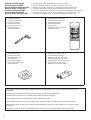 2
2
-
 3
3
-
 4
4
-
 5
5
-
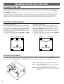 6
6
-
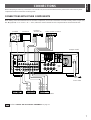 7
7
-
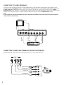 8
8
-
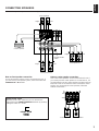 9
9
-
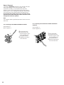 10
10
-
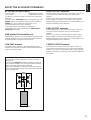 11
11
-
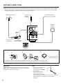 12
12
-
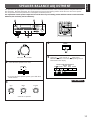 13
13
-
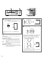 14
14
-
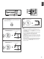 15
15
-
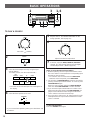 16
16
-
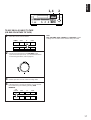 17
17
-
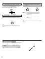 18
18
-
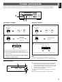 19
19
-
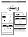 20
20
-
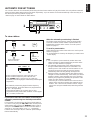 21
21
-
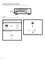 22
22
-
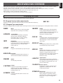 23
23
-
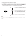 24
24
-
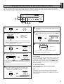 25
25
-
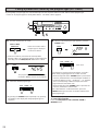 26
26
-
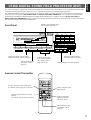 27
27
-
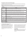 28
28
-
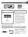 29
29
-
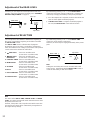 30
30
-
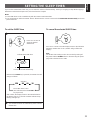 31
31
-
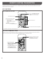 32
32
-
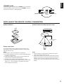 33
33
-
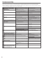 34
34
-
 35
35
-
 36
36


Yamaha RX-V590RDS Manual de usuario
- Categoría
- Receptor
- Tipo
- Manual de usuario
en otros idiomas
- français: Yamaha RX-V590RDS Manuel utilisateur
- italiano: Yamaha RX-V590RDS Manuale utente
- English: Yamaha RX-V590RDS User manual
- Deutsch: Yamaha RX-V590RDS Benutzerhandbuch
- русский: Yamaha RX-V590RDS Руководство пользователя
- Nederlands: Yamaha RX-V590RDS Handleiding
- português: Yamaha RX-V590RDS Manual do usuário
- dansk: Yamaha RX-V590RDS Brugermanual
- polski: Yamaha RX-V590RDS Instrukcja obsługi
- čeština: Yamaha RX-V590RDS Uživatelský manuál
- svenska: Yamaha RX-V590RDS Användarmanual
- Türkçe: Yamaha RX-V590RDS Kullanım kılavuzu
- suomi: Yamaha RX-V590RDS Ohjekirja
- română: Yamaha RX-V590RDS Manual de utilizare
Artículos relacionados
-
Yamaha RX-V480 Manual de usuario
-
-
-
-
-
-
-
-
-