GE AV447FBS El manual del propietario

Categoría
Campanas de cocina
Tipo
El manual del propietario
Español
For a Spanish version of this
manual, visit our Website at
GEAppliances.com.
Para consultar una version
en español de este manual de
instrucciones, visite nuestro sitio
de internet GEAppliances.com.
49-80589-6 11-15 GE
Safety Instructions ............ 2
Warranty ...................... 4
Assistance / Accessories ..... 5
Using The Hood
Controls .........................6
Care and Cleaning
Filters ............................6
Surfaces.........................7
Light .............................7
Installation Instructions ......8
Troubleshooting Tips ........16
Write the model and serial numbers here:
Model # ______________________
Serial # _______________________
You can find them on a label on the back
wall of the hood.
Owner’s Manual and
Installation Instructions
JV247*– Vent & Recirculation options
JV248*– Vent & Recirculation options
JN327–Recirculation only
JN328–Recirculation only
JV338*–Vent options only
JV347*– Vent & Recirculation options
JV348*– Vent & Recirculation options
JV367*– Vent & Recirculation options
RN328–Recirculation only
AV447*– Vent & Recirculation options
Range Hoods
*
2
49-80589-6
READ AND SAVE THESE INSTRUCTIONS
IMPORTANT SAFETY INFORMATION.
READ ALL INSTRUCTIONS BEFORE USING.
SAFETY INFORMATION
This is the safety alert symbol. This symbol alerts you to potential hazards that can kill or hurt you and others.
All safety messages will follow the safety alert symbol and the word “DANGER”, “WARNING”, or “CAUTION”. These
words are defined as:
DANGER
Indicates a hazardous situation which, if not avoided, will result in death or serious injury.
WARNING
Indicates a hazardous situation which, if not avoided, could result in death or serious injury.
CAUTION
Indicates a hazardous situation which, if not avoided, could result in minor or moderate injury.
SAFETY PRECAUTIONS
WARNING
TO REDUCE THE RISK OF FIRE,
ELECTRIC SHOCK OR INJURY TO PERSONS,
OBSERVE THE FOLLOWING:
A. Use this unit only in the manner intended by the
manufacturer. If you have questions, contact the
manufacturer.
B. Before servicing or cleaning unit, switch power
off at service panel and lock the service
disconnecting means to prevent power from
being switched on accidentally. When the
service disconnecting means cannot be locked,
securely fasten a prominent warning device,
such as a tag, to the service panel.
C. Do not use this unit with any solid-state speed
control device.
D. This unit must be grounded.
CAUTION
FOR GENERAL VENTILATING USE
ONLY. DO NOT USE TO EXHAUST HAZARDOUS
OR EXPLOSIVE MATERIALS AND VAPORS.
CAUTION
TO REDUCE RISK OF FIRE AND TO
PROPERLY EXHAUST AIR, BE SURE TO DUCT
AIR OUTSIDE. DO NOT VENT EXHAUST AIR
INTO SPACES WITHIN WALLS OR CEILINGS OR
INTO ATTICS, CRAWL SPACES OR GARAGES.
WARNING
TO REDUCE THE RISK OF INJURY
TO PERSONS IN THE EVENT OF A RANGE TOP
GREASE FIRE, OBSERVE THE FOLLOWING*:
A. SMOTHER FLAMES with a close-fitting lid,
cookie sheet or metal tray, then turn off the
burner. BE CAREFUL TO PREVENT BURNS.
If the flames do not go out immediately,
EVACUATE AND CALL THE FIRE
DEPARTMENT.
B. NEVER PICK UP A FLAMING PAN—You may
be burned.
C. DO NOT USE WATER, including wet dishcloths
or towels—a violent steam explosion will result.
D. Use an extinguisher ONLY if:
1. You know you have a Class ABC extinguisher,
and you already know how to operate it.
2. The fire is small and contained in the area
where it started.
3. The fire department is being called.
4. You can fight the fire with your back to an exit.
*Based on “Kitchen Fire Safety” published by NFPA.
49-80589-6
3
READ AND SAVE THESE INSTRUCTIONS
SAFETY INFORMATION
SAFETY PRECAUTIONS
WARNING
TO REDUCE THE RISK OF A
RANGE TOP GREASE FIRE:
A. Never leave surface units unattended at high
settings. Boilovers cause smoking and greasy
spillovers may ignite. Heat oils slowly on low or
medium settings.
B. Always turn hood ON when cooking on high heat
or when flambéing food (i.e. Crepes Suzette,
Cherries Jubilee, Peppercorn Beef Flambé).
C. Clean ventilating fans frequently. Grease should
not be allowed to accumulate on fan or filter.
D. Use proper pan size. Always use cookware
appropriate for the size of the surface element.
WARNING
TO REDUCE THE RISK OF FIRE,
ELECTRIC SHOCK OR INJURY TO PERSONS,
OBSERVE THE FOLLOWING:
A. Installation work and electrical wiring must be
done by qualified person(s) in accordance with
all applicable codes and standards, including
fire-rated construction.
B. Sufficient air is needed for proper combustion
and exhausting of gases through the flue
(chimney) of fuel burning equipment to prevent
back drafting. Follow the heating equipment
manufacturer’s guidelines and safety standards
such as those published by the National Fire
Protection Association (NFPA), the American
Society for Heating, Refrigeration and Air
Conditioning Engineers (ASHRAE) and the local
code authorities.
C. When cutting or drilling into wall or ceiling, do
not damage electrical wiring and other hidden
utilities.
D. Ducted fans must always be vented to the
outdoors.
E. When applicable, install any makeup
(replacement) air system in accordance
with local building code requirements. Visit
GEAppliances.com for available makeup air
solutions.
F. Turn off breaker to adjacent rooms while
working.
WARNING
TO REDUCE THE RISK OF FIRE,
USE ONLY METAL DUCTWORK.
Ŷ Do not attempt to repair or replace any part of
your hood unless it is specifically recommended
in this manual. All other servicing should be
referred to a qualified technician.
4
49-80589-6
GE Warranty
GEAppliances.com
All warranty service is provided by our Factory Service Centers, or an authorized Customer Care
®
technician.
To schedule service, on-line, visit us at www.geappliances.com/service_and_support/, or call 800.GE.CARES
(800.432.2737). Please have serial number and model number available when calling for service.
Servicing your appliance may require the use of the onboard data port for diagnostics. This gives a GE factory
service technician the ability to quickly diagnose any issues with your appliance and helps GE improve its products
by providing GE with information on your appliance. If you do not want your appliance data to be sent to GE, please
advise your technician not to submit the data to GE at the time of service.
For the period of one year from the date of the original purchase, GE will provide any part of the hood which fails due
to a defect in materials or workmanship. During this limited one-year warranty, GE will also provide, free of charge, all
labor and in-home service to replace the defective part.
What GE will not cover:
Ŷ Service trips to your home to teach you how to use
the product.
Ŷ Improper installation, delivery or maintenance.
Ŷ Failure of the product if it is abused, misused,
modified or used for other than the intended purpose
or used commercially.
Ŷ Replacement of house fuses or resetting of circuit
breakers.
Ŷ Damage to the product caused by accident, fire,
floods or acts of God.
Ŷ Damage to finish, such as surface rust, tarnish, or
small blemishes not reported within 48 hours of
delivery.
Ŷ Incidental or consequential damage caused by
possible defects with this appliance.
Ŷ Damage caused after delivery.
Ŷ Product not accessible to provide required service.
Ŷ Service to repair or replace light bulbs, except for
LED lamps.
EXCLUSION OF IMPLIED WARRANTIES
Your sole and exclusive remedy is product repair as provided in this Limited Warranty. Any implied warranties,
including the implied warranties of merchantability or fitness for a particular purpose, are limited to one year or the
shortest period allowed by law.
This warranty is extended to the original purchaser and any succeeding owner for products purchased for home use
within the USA. If the product is located in an area where service by a GE Authorized Servicer is not available, you
may be responsible for a trip charge or you may be required to bring the product to an Authorized GE Service location
for service. In Alaska, the warranty excludes the cost of shipping or service calls to your home.
Some states do not allow the exclusion or limitation of incidental or consequential damages. This warranty gives you
specific legal rights, and you may also have other rights which vary from state to state. To know what your legal rights
are, consult your local or state consumer affairs office or your state’s Attorney General.
Warrantor: General Electric Company. Louisville, KY 40225
Extended Warranties: Purchase a GE extended warranty and learn about special discounts that are available while
your warranty is still in effect. You can purchase it on-line anytime
www.geappliances.com/service_and_support/shop-for-extended-service-plans.htm
or call 800.626.2224 during normal business hours. GE Consumer Home Services will still be there after your
warranty expires.
Register Your Appliance: Register your new appliance on-line at your convenience!
www.geappliances.com/service_and_support/register/
Timely product registration will allow for enhanced communication and prompt service under the terms of your warranty,
should the need arise. You may also mail in the pre-printed registration card included in the packing material.
Staple your receipt here. Proof of the original purchase
date is needed to obtain service under the warranty.
WARRANTY
Thank You! ... for your purchase of a GE Brand appliance.
49-80589-6
5
Schedule Service: Expert GE repair service is only one
step away from your door. Get on-line and schedule your
service at www.geappliances.com/service_and_support/
Or call 800.GE.CARES (800.432.2737) during normal
business hours.
Parts and Accessories: Individuals qualified to service
their own appliances can have parts or accessories sent
directly to their homes (VISA, MasterCard and Discover
cards are accepted).Order on-line today, 24 hours
every day or by phone at 800.626.2002 during normal
business hours.
Instructions contained in this manual cover procedures
to be performed by any user. Other servicing generally
should be referred to qualified service personnel. Caution
must be exercised, since improper servicing may cause
unsafe operation.
Real Life Design Studio: GE supports the Universal
Design concept of products, services and environments
that can be used by people of all ages, sizes and
capabilities. We recognize the need to design for a wide
range of physical and mental abilities and impairments.
For details of GE’s Universal Design applications,
including kitchen design ideas for people with disabilities,
check out our Website today. For the hearing impaired,
please call 800.TDD.GEAC (800.833.4322).
Contact Us: If you are not satisfied with the service you
receive from GE, contact us on our Website with all the
details including your phone number, or write to:
General Manager, Customer Relations
GE Appliances, Appliance Park Louisville, KY 40225
Try the GE Appliances Website (www.geappliances.com/service_and_support/) 24 hours a day, any day of the
year! For greater convenience and faster service, you can now download Owner’s Manuals, order parts or even
schedule service on-line.
Accessories
Looking For Something More?
GE offers a variety of accessories to improve your cooking and maintenance experiences!
To place an order visit us online at:
www.GEApplianceParts.com
or call 800.626.2002
The following products and more are available:
How to Remove Protective Shipping Film and Packaging Tape
Carefully grasp a corner of the protective shipping film
with your fingers and slowly peel it from the appliance
surface. Do not use any sharp items to remove the film.
Remove all of the film before using the appliance for the
first time.
To assure no damage is done to the finish of the
product, the safest way to remove the adhesive from
packaging tape on new appliances is an application of
a household liquid dishwashing detergent. Apply with a
soft cloth and allow to soak.
NOTE: The adhesive must be removed from all parts.
Parts
Charcoal Filter WB02X10700
Have a question or need assistance with your appliance?
ASSISTANCE / ACCESSORIES
6
49-80589-6
Throughout this manual, features and appearance may vary from your model.
Control Knobs (on some models)
1. FAN Control: Turn to HI, MED or LO as needed.
Continuous use of the fan system while cooking
helps keep the kitchen comfortable and less humid.
It also reduces cooking odors and soiling moisture
that create a frequent need for cleaning.
2. LIGHT Control: Turn to ON while cooking or to
NITE for use as a night light.
Switch Pad Controls (on some models)
1. LIGHT Control: Press the pad at the top to turn
the light ON.
2. Fan Settings Buttons: Press the pad at the
top to turn the fan on HI and at the bottom to turn it
on LO. The center position is OFF.
Continuous use of the fan system while cooking
helps keep the kitchen comfortable and less humid.
It also reduces cooking odors and soiling moisture
that create a frequent need for cleaning.
Be sure electrical power is off and all surfaces are cool before cleaning or servicing any part of the vent hood.
5HXVDEOH0HWDO*UHDVH)LOWHU³'XFWHG,QVWDOODWLRQV2QO\
The efficiency of your hood depends on a clean filter.
Frequency of cleaning depends on hood use and the
type of cooking you do. However, the grease filter should
be cleaned at least once a month.
To remove:
Pull down on the center of the front edge of the filter. The
filter will then slip out of the retaining tabs on the back.
To replace:
Slip the back edge of the filter into the retaining tabs and
push the front edge up until it snaps into place.
To clean:
Soak and then agitate it in a hot water and detergent
solution. Light brushing can be used to remove embedded
dirt. Rinse, shake and let it dry before replacing.
NEVER OPERATE THE HOOD WITHOUT THE FILTER
IN PLACE.
With careful handling, the metal filter will last for years. If
a new replacement filter becomes necessary, order the
part from your dealer. Order genuine GE part number
WB02X8391.
USING THE HOOD: Controls / CARE AND CLEANING: Filters
Controls
Filters
(AV447 models only)
LO HI
MED NITE
OFF
OFF
ON
LO
HI ON
MED
OFF OFF
NITE
1
1
2
2
LO
OF
F
HI
OFF
ON
12
Grease filter
49-80589-6
7
CARE AND CLEANING: Filters / Surfaces / Light
&KDUFRDO)LOWHU³5HFLUFXODWLQJ,QVWDOODWLRQV2QO\
The charcoal filter cannot be cleaned. It must be
replaced. Order filter no. WB02X10700. Replacement
filters can be ordered from your GE supplier.
If the hood is not vented to the outside, the air will be
recirculated through a disposable charcoal filter that
helps remove smoke and odors.
The charcoal filter should be replaced after 6 to 12
months (depending on hood usage).
To remove:
Pull down on the center of the front edge of the filter. The
filter will then slip out of the retaining tabs on the back.
To replace:
Slip the back edge of the filter into the retaining tabs and
push the front edge up until it snaps into place.
NOTE: DO NOT rinse, or put charcoal filters in an
automatic dishwasher.
Filters (Cont.)
Replaceable charcoal filter
CAUTION
Let the light bulb cool completely before
removing. A warm or hot bulb may break if touched with
a moist cloth or hand.
Remove the bulb and replace it with a type A15
incandescent light bulb with an ordinary screw base,
not more than 60 Watts, or a type A17 or T2 Compact
Fluorescent (CFL) light bulb with an ordinary screw base,
not more than 13 Watts. NOTE: Use only incandescent
bulbs in models RN328, JN327, JN328 and JV338.
IMPORTANT: For installation, handling and disposal
precautions, refer to the fluorescent bulb packaging
literature.
To remove the light cover (on some models):
Ŷ 3UHVVWKHVLGHVZLWKWZRILQJHUVXQWLO
the side prongs are released.
Ŷ /LIWWKHOLJKWFRYHUDQGVOLGHLWWRZDUG
you in one motion.
To replace the light cover:
Ŷ ,QVHUWWKHSURQJORFDWHGDWWKHHQGRIWKHFRYHULQWR
the top opening.
Ŷ *HQWO\SXVKWKHFRYHUXSDQGSUHVVWKHVLGHVWRILW
the side prongs into the side openings.
Ŷ 5HOHDVHDQGWKHFRYHUZLOOORFNLQSRVLWLRQ
Painted Surfaces (on some models)
Do not use steel-wool pads or other abrasive
cleaners. They will scratch the surface.
Clean grease-laden surfaces of the hood frequently. To
clean the hood surface, use a hot, damp cloth with a
mild detergent suitable for painted surfaces. About one
tablespoon of ammonia may be added to the water. Use
a clean, hot, damp cloth to remove soap. Dry with a dry,
clean cloth.
NOTE: When cleaning, take care not to come in contact
with filters and other non-enameled surfaces.
CAUTION
When cleaning the hood surfaces, be
certain that you do not touch the light bulb with moist
hands or cloth. A warm or hot light bulb may break if
touched with a moist surface. Always let the light bulb
cool completely before cleaning around it.
Stainless Steel Surfaces (on some models)
Do not use a steel-wool pad; it will scratch the
surface.
To clean the stainless steel surface, use warm sudsy
water or a stainless steel cleaner or polish. Always wipe
the surface in the direction of the grain. Follow the cleaner
instructions for cleaning the stainless steel surface.
To inquire about purchasing stainless steel appliance
cleaner or polish, or to find the location of a dealer
nearest you, please call our toll-free number:
National Parts Center
800.626.2002
GEApplianceParts.com
Surfaces
Light
When using an energy saving bulb in your GE hood
make sure you use either:
GE Long Life Energy Smart™ Spiral
®
T2
Product Code: 85383
Description: FLE13HT2/2/SW/CD
or
GE Long Life Energy Smart™ A17
Product Code: 47486
Description: FLE11/2/A17XL/CD
Available at www.gelighting.com
Light cover
8
49-80589-6
Installation
Instructions
“If you have questions, call 800.GE.CARES (800.432.2737) or visit our website at: GEAppliances.com”
BEFORE YOU BEGIN
Read these instructions completely and
carefully.
IMPORTANT Save these
instructions for local inspector’s use.
IMPORTANT Observe all governing
codes and ordinances.
Note to Installer – Be sure to leave these
instructions with the Consumer.
Note to Consumer – Keep these
instructions for future reference.
Skill level – Installation of this vent hood
requires basic mechanical and electrical
skills.
Proper installation is the responsibility of the
installer.
Product failure due to improper installation is
not covered under the Warranty.
FOR YOUR SAFETY:
WARNING
Before beginning the installation,
switch power off at service panel and lock the
service disconnecting means to prevent power
from being switched on accidentally. When the
service disconnecting means cannot be locked,
securely fasten a prominent warning device,
such as a tag, to the service panel.
OPTIONAL POWER CORD KIT JXHC1
An optional Power Cord Connection Kit, model
JXHC1, is available at extra cost from your
GE supplier for installation using a standard
3-prong, grounded wall outlet. Follow the
Installation Instructions packed with the kit to
connect the power cord to the range hood.
DUCTWORK REQUIREMENTS
NOTE: Read the ductwork sections only if you do not
have existing ductwork. If you have existing ductwork,
skip to the “Damage” section and proceed.
WARNING
TO REDUCE THE RISK OF FIRE AND
TO PROPERLY EXHAUST AIR, BE SURE TO DUCT
AIR OUTSIDE—DO NOT VENT EXHAUST AIR INTO
SPACES WITHIN WALLS OR CEILINGS OR INTO
ATTICS, CRAWL SPACES OR GARAGES.
The venting system must exhaust to the outside.
This hood can be vented vertically through upper
cabinets or horizontally through an outside wall.
Ductwork is not included.
Exhaust connection:
The hood exhaust has been designed to mate with
VWDQGDUG»Ǝ[ƎUHFWDQJXODUGXFWLQJRUƎGLDPHWHU
round ducting.
,IDƎURXQGGXFWLVUHTXLUHGDUHFWDQJXODUWRURXQG
transition adaptor must be used*. Do not use less than
DƎ diameter duct.
Duct length:
It is important that ducting be installed using the most
direct route and with as few elbows as possible. This
ensures clear venting of exhaust and helps prevent
blockages. Also, make sure dampers swing freely
and nothing is blocking the ducts. When applicable,
install any makeup (replacement) air system in
accordance with local building code requirements. Visit
GEAppliances.com for available makeup air solutions.
Plan the route for venting exhaust to the outdoors.
To maximize the ventilation performance of the vent
system:
1. Minimize the duct run length and number of
transitions and elbows.
2. Maintain a constant duct size.
3. Seal all joints with duct tape to prevent any leaks.
4. Do not use any type of flexible ducting.
Install a wall cap or roof cap with damper at the
exterior opening. Purchase the wall or roof cap and
any transition and length of duct needed in advance.
* IMPORTANT: If a rectangular-to-round
transition adaptor is used, the bottom
corners of the damper will have to be cut
to fit, using the tin snips, in order to allow
free movement of the damper. Equivalent
lengths of duct pieces are based on
actual tests and reflect requirements for
good venting performance with any hood.
Range Hood
INSTALLATION INSTRUCTIONS
49-80589-6
9
INSTALLATION INSTRUCTIONS
Installation Instructions
DAMAGE – SHIPMENT/INSTALLATION
If the unit is damaged in shipment, return the
unit to the store in which it was bought for repair
or replacement.
If the unit is damaged by the customer,
repair or replacement is the responsibility of the
customer.
If the unit is damaged by the installer (if other
than the customer), repair or replacement must
be made by arrangement between customer and
installer.
TOOLS YOU WILL NEED
PARTS INCLUDED
MOUNTING SPACE
NOTES:
• Hood width may be greater than the width of the
range or cooktop, but it may not be smaller.
• Ensure the range or cooktop is installed per
manufacturer’s installation instructions.
• If you are going to vent your range hood to the
outside, see the “Ducting Requirements” section
for exhaust duct preparation.
66s or more
from the
floor to the
top of the
hood
24s,30s or 36
s to
match cooktop
width
30s
min.
Bottom edge of
cabinet needs
to be 30s or
more from
the cooking
surface
Flat-blade and Phillips
screwdrivers
Pencil
Metal snips
(in some
applications)
Electric drill
Saw (saber or
keyhole)
Duct tape
Pliers
Level
Caulking
Tape measure
1/4s
pivoting
hex socket
Flashlight
Wire stripper
1/4s Nutdriver
PART QUANTITY
Grease Filter only (JV338) 1
Charcoal Filter only
(JN327, JN328 and RN328)
1
Grease Filter and
Charcoal Filter
(JV24X, JV347, JV348,
JV367 and AV447)
2
Mounting Screws
(8 - 18" x 3/4" Phillips pan
head)
4
Exhaust Adaptor
(for 3 1/4" x 10" rect.
venting)
1
Exhaust Adaptor Screw
(8 - 18" x 3/8" Phillips pan
head or hex head)
1
10
49-80589-6
Installation Instructions
1
CHOOSE VENT OPTION
Determine the vent option that your installation
will require and that is available for your model
from the below choices.
IMPORTANT: If the hood is to be installed in a
recirculating, non-vented, ductless manner, do not
knock out any vent openings in the hood. Only an
electrical access hole will be knocked out of the hood.
A
Outside top exhaust
(Vertical duct–3-1/4" x 10" Rectangular)
C
Outside rear exhaust
(Horizontal duct–3-1/4" x 10" Rectangular)
B
Outside top exhaust
(Vertical duct–7" Round)
D
Recirculating
(non-vented/ductless)
JV338
JN327
JN328
RN328
JV247
JV248
JV347
JV348
JV367
AV447
JV247
JV248
JV347
JV348
JV367
AV447
JV338 JV338
JV247
JV248
JV347
JV348
JV367
AV447
JV247
JV248
JV347
JV348
JV367
AV447
INSTALLATION INSTRUCTIONS
49-80589-6
11
INSTALLATION INSTRUCTIONS
Installation Instructions
2
REMOVE EXHAUST ADAPTOR
,IH[KDXVWLQJYHQWLQJXVLQJWKHƎ[
ƎUHFWDQJXODUGXFW²RSWLRQDOIRU-9
JV248, JV338, JV347, JV348, JV367 and
AV447 models only:
Remove the exhaust adaptor from the inside of
the hood. Set it aside along with its mounting
screws.
5
REMOVE WIRING COVER
Remove the wiring cover from inside the hood.
Set the cover and its mounting screws aside.
6
REMOVE WIRING KNOCKOUT
Remove either the top or the back wiring
knockout as needed and install an approved
strain relief clamp.
7
REMOVE DUCT KNOCKOUT
If recirculating, non-vented ductless (JN327,
JN328 and RN328, and optional for JV247,
JV248, JV347, JV348, JV367 and AV447
models only), skip to Step 11 D and proceed.
Using a flat-blade screwdriver, remove the
appropriate duct knockout from the top or
back of the hood.
3
REMOVE FILTER
Remove the shipping tape holding the metal
grease filter in place. Pull down on the center
of the front edge of the filter. The filter will then
slip out of the retaining tabs on the back.
4
REVERSE THE BAFFLE FOR DUCTED
INSTALLATIONS ONLY
(JV247, JV248,
JV347, JV348, JV367 and AV447 models)
If the hood is to be recirculated, skip to the
next step. Remove the baffle from the top of
the hood. Reinstall the baffle so the short side
marked “VENTED” is visible. The long side of
the baffle should be inside the hood.
3
1
ø4s x 10s
rectangular
exhaust
adaptor
and screws
Metal grease filter
“VENTED” is visible
Wiring
cover
Strain relief
clamp
Back
knockout
Top
knockout
Strain relief
clamp
3
1
ø4s x 10s Rectangular
vertical discharge.
Remove top rectangular
duct knockout only.
7s Round vertical discharge.
Remove circular duct
knockout only.
3
1
ø4s x 10s Rectangular horizontal
discharge. Remove rear
rectangular duct knockout only.
12
49-80589-6
Installation Instructions
8
FOR 3-1-4" X 10" RECTANGULAR
DUCTED DISCHARGE INSTALLATIONS
ONLY:
Attach exhaust adaptor/damper over the
appropriate knockout opening (for vertical or
horizontal, depending on installation) with two
exhaust adaptor screws. Make sure damper
pivot is nearest to top/back edge of hood.
Remove tape from damper flap.
10
FOR RECESSED-BOTTOM CABINETS
ONLY
If the cabinets have front, side or back trim,
PDNHZRRGVKLPVDPLQLPXPRIƎWKLFN
and cut to fit the width of the inner recessed
cabinet bottom. Attach them to the cabinet
bottom recess on both sides. See Step 11 for
marking locations.
9
FOR 7" ROUND VERTICAL DUCTED
DISCHARGE INSTALLATIONS ONLY:
Bend up the duct alignment ears in preparation
IRUODWHUDWWDFKPHQWRIWKHƎGXFW
Tape
Top/back edge
Exhaust adaptor/damper
(vertical discharge position)
Pivot
(depending on
installation)
Exhaust adaptor/damper
(horizontal discharge position)
Attachment ear tabs
Wood shims
(minimum thickness 3/8s
INSTALLATION INSTRUCTIONS
49-80589-6
13
INSTALLATION INSTRUCTIONS
Installation Instructions
11
MARK HOLES
Select the vent option that your installation will
require and proceed to that section:
A
Outside top exhaust
(Vertical duct–3-1/4" x 10" Rectangular)
Use the diagram or the hood as a template and
mark the locations on the cabinet for ductwork,
electrical wiring and keyhole screw slots.
B
Outside top exhaust
(Vertical duct–7" Round)
Use the diagram or the hood as a template and
mark the locations on the cabinet for ductwork,
electrical wiring and keyhole screw slots.
12
CUT HOLES
Cut holes at marked locations for duct and
electrical wiring. For the vertical duct, cut out
ƎH[WUDWRZDUGWKHIURQWRIWKHFDELQHWVR
you can move the duct freely when installing
the hood. It may also ease installation by
FXWWLQJWKHKROH»ƎLQVWHDGRIƎ
13
RUN WIRES
Run the electrical wires through the wall or
cabinet according to National Electrical Code
and applicable local codes.
NOTE: DO NOT turn the power on until
installation is complete.
C
Outside rear exhaust
(Horizontal duct–3-1/4" x 10" Rectangular)
Use the diagram or the hood as a template and
mark the locations on the cabinet for ductwork,
electrical wiring and keyhole screw slots.
D
Recirculating (non-vented ductless–
JN327, JN328 and RN328, and optional on
JV247, JV248, JV347, JV348, JV367 and
AV447 models only)
Use the hood as a template and mark the
locations on the cabinet for the electrical
wiring and keyhole screw slots.
Since the hood is to be recirculated (not to
be vented outside), do not cut out any vent
openings in the wall or cabinet bottom.
Hood mounting screws (4)
10
3
ø4s (24s hood)
13
3
ø4s (30s hood)
16
3
ø4s (36s hood)
10
3
ø4s (24s hood)
13
3
ø4s (30s hood)
16
3
ø4s (36s hood)
Cabinet front
Center
line
Electrical access
hole (in cabinet bottom)
Wood shims (recessed-
bottom cabinets only–shims
must be a minimum of 3/8s
thick and cut to fit the width
of the inner recessed cabinet
bottom)
Access
hole for 7s
round duct
9
5
ø8s
1
3
ø8s
1
1
ø4s
7
3
ø4s
5
3
ø4s
Cabinet
bottom
8s DIA.
HOLE
Hood mounting
screws (4)
10
3
ø4s (24s hood)
13
3
ø4s (30s hood)
16
3
ø4s (36s hood)
10
3
ø4s (24s hood)
13
3
ø4s (30s hood)
16
3
ø4s (36s hood)
Cabinet front
Center
line
Electrical access hole
(in cabinet bottom)
Wood shims
(recessed-bottom
cabinets only–shims
must be a minimum
of 3/8s thick and cut
to fit the width of
the inner recessed
cabinet bottom)
9
5
ø8s
1
3
ø8s
1
1
ø4s
7
3
ø4s
3
3
ø4s
1
ø2s
5
1
ø4s
5
1
ø4s
Cabinet Bottom
Vertical duct
access hole
Wood shims
(recessed-bottom cabinets only–shims must be
a minimum of 3/8s thick and cut to fit the width
of the inner recessed cabinet bottom)
Cabinet front
Center line
Electrical access
hole (in wall)
Hood mounting
screws (4)
Cabinet
bottom
10
3
ø4s (24s hood)
13
3
ø4s (30s hood)
16
3
ø4s (36s hood)
1
1
ø4s
1
ø2s
3
3
ø4s
5
1
ø4s
5
1
ø4s
7
3
ø4s
10
3
ø4s (24s hood)
13
3
ø4s (30s hood)
16
3
ø4s (36s hood)
Horizontal duct
access hole
14
49-80589-6
Installation Instructions
14
SCREW IN PART WAY
Drive a mounting screw (from the hardware
packet) part way into each center of the
narrow neck of the keyhole slots marked on
the cabinet bottom.
17
SECURE HOOD
Slide the hood back against the wall. Tighten
the mounting screws. Be sure the screw heads
are in the narrow neck of the keyhole slot.
NOTE: DO NOT PUSH ON THE FAN BLADE.
Pushing on the blade may cause it to interfere
with other hood parts.
17
CONNECT DUCTWORK TO HOOD
(Ducted installations only)
2QƎURXQGLQVWDOODWLRQVDWWDFKWKHƎGXFW
with sheet metal screws through the holes in
the alignment ears.
Use duct tape to make joints secure and
airtight.
16
FEED IN WIRES
Lift the hood into position and feed the house
wiring through the wiring knockout.
15
OPTIONAL POWER CORD KIT JXHC1
An optional Power Cord Connection Kit, model
JXHC1, is available at extra cost from your
GE supplier for installation using a standard
3-prong, grounded wall outlet. Follow the
Installation Instructions packed with the kit to
connect the power cord to the range hood.
NOTE: If using optional Power Cord Kit
JXHC1, feed the power cord through the hole
in the top cabinet while raising the hood. Loop
any excess length of cord and tie away with a
suitable tape or tie.
Cabinet
7
3
ø4s
3-prong
wall outlet
(if using cord
connection)
1
1
ø4s
1
3
ø4sdia. clearance hole
for optional power
supply location
C
L
Keyhole (4)
Mounting
screw (4)
Attachment ear tabs
7s round duct
Duct tape
INSTALLATION INSTRUCTIONS
49-80589-6
15
INSTALLATION INSTRUCTIONS
19
INSTALL LIGHT BULB
NOTE: A light bulb is not shipped with the hood.
Obtain one locally. Purchase and install a type
A15 incandescent light bulb with an ordinary
screw base, not more than 60 Watts, or a type
A17 or T2 Compact Fluorescent (CFL) light bulb
with an ordinary screw base, not more than 13
Watts. NOTE: Use only incandescent bulbs in
models RN328, JN327, JN328 and JV338.
IMPORTANT: For installation, handling and
disposal precautions, refer to the fluorescent
bulb packaging literature.
When using an energy saving bulb in your GE
hood, make sure you use either:
22
REPLACE WIRING COVER
23
REPLACE FILTER
Make sure fan blade turns freely and replace
the filter. NOTE: Install the metal grease filter if
ducted or the charcoal filter if recirculated.
The installation is complete. Turn on power at
service panel, and test for proper operation.
TROUBLESHOOTING CHECKLIST
If the hood seems to be operating at high speed
when the control is not set on high, or if ventilation
seems inadequate, check the following:
Knockouts not removed from hood.
Damper blade not opening.
Reduced airflow because the duct is too small or
the duct length is too long.
The duct is blocked.
Undersized or restrictive wall or roof cap.
If the hood seems to make excessive noise:
Fan may be hitting the filter. Turn off the fan and
remove the filter. Bend the filter down slightly
in the center (into a dome shape) to allow fan
clearance. Reinstall and adjust as needed.
The fan does not work but the lights do:
Switch power off at the service panel and lock
the service disconnecting means to prevent
power from being switched on accidentally.
When the service disconnecting means cannot
be locked, securely fasten a prominent warning
device, such as a tag, to the service panel.
Check the wiring connections. See the
CONNECT WIRING section in these Installation
Instructions.
20
FOLLOW ELECTRICAL CODE
Complete the electrical wiring according to
National Electrical Code and local codes.
NOTE: This hood must be permanently grounded.
Connect house wiring (120 VAC) to hood wiring.
21
CONNECT WIRING
Connect house black to hood black wire,
house white to
hood white wire and
house ground under
green ground screw.
Securely tighten the
strain relief clamp
onto the house wiring.
WARNING
IMPROPER CONNECTION
OF ALUMINUM HOUSE WIRING TO
THESE COPPER LEADS CAN RESULT
IN A SERIOUS PROBLEM. USE ONLY
CONNECTORS DESIGNED FOR JOINING
COPPER TO ALUMINUM AND FOLLOW
THE MANUFACTURER’S RECOMMENDED
PROCEDURE CLOSELY.
Installation Instructions
GE Long Life Energy
Smart
Spiral
®
T2
Product Code: 85383
Description:
FLE13HT2/2/SW/CD
GE Long Life Energy
Smart
A17
Product Code: 47486
Description:
FLE11/2/A17XL/CD
Available at
www.gelighting.com
or
Green
ground
screw
Wiring cover
Metal grease filter or charcoal filter
16
49-80589-6
Troubleshooting tips ... Before you call for service
Save time and money! Review the charts on the following pages first and you may not need to call for service.
Problem Possible Cause What To Do
Fan/Light does not operate A house fuse may be blown or
a circuit breaker tripped.
Replace fuse or reset circuit breaker.
Loud or abnormal airflow
noise
Wrong duct size used in
installation.
Using smaller duct pipe will cause reduced venting.
Minimize the duct run length and number of transitions
and elbows. GE service technicians cannot correct this
issue if installed improperly.
Fan fails to circulate
air or moves air slower
than normal and/or fan is
making loud or abnormal
airflow noise
Obstructions in duct work. Make sure nothing is blocking the vent. Make sure your
wall or roof cap has a blade or door.
Damper blade on wall or roof
cap may not be open.
Make sure damper swings freely. Damper blades may flip
over and will not fully open when this happens. Adjust to
original position.
Metal grease filter and charcoal
filter (if present) may be dirty.
Clean the metal grease filter and replace charcoal filter (if
present). See Care and Cleaning of the Vent Hood.
Insufficient makeup
(replacement) air
Sufficient makeup (replacement) air is required for
exhausting appliances to operate to rating. Check with
local building codes, which may require or strongly
advise the use of makeup air. Visit GEAppliances.com for
available makeup air solutions.
Early light failure Light wattage is too high. Replace with correct wattage.
TROUBLESHOOTING TIPS
*
49-80589-6 11-15 GE
Información de Seguridad ....... 2
Garantía .......................... 4
Asistencia / Accesorios .......... 5
Uso de la Campana
Controles ............................6
Cuidado y Limpieza
Filtros ................................6
Superficies ...........................7
Luz ..................................7
Instrucciones de instalación .....8
Consejos Para la
Solución de Problemas .......16
Escriba los números de modelo y serie aquí:
Nº de modelo __________________
Nº de serie ____________________
Los puede encontrar en una etiqueta en la
pared trasera de la campana.
JV247*– Opciones de Ventilación y
Recirculación
JV248*– Opciones de Ventilación y
Recirculación
JN327–Sólo recirculación
JN328–Sólo recirculación
JV338*–Sólo opciones de ventilación
JV347*– Opciones de Ventilación y
Recirculación
JV348*– Opciones de Ventilación y
Recirculación
JV367*– Opciones de Ventilación y
Recirculación
RN328–Sólo recirculación
AV447*– Opciones de Ventilación y
Recirculación
Campanas
para Hornos
Manual del propietario
e Instrucciones
de Instalación
2
49-80760
LEA Y GUARDE ESTAS INSTRUCCIONES
INFORMACIÓN IMPORTANTE DE SEGURIDAD
LEA TODAS LAS INSTRUCCIONES ANTES DE USAR
INFORMACIÓN DE SEGURIDAD
Éste es el símbolo de alerta de seguridad. El mismo alerta sobre potenciales riesgos que le pueden producir la muerte o
lesiones tanto a usted como a otras personas. Todos los mensajes de seguridad estarán a continuación del símbolo de alerta de
seguridad y con la palabra “PELIGRO”, “ADVERTENCIA” o “PRECAUCIÓN”. Estas palabras se definen como:
PELIGRO
Indica una situación de riesgo que, si no se evita, producirá la muerte o lesiones graves.
ADVERTENCIA
Indica una situación de riesgo que, si no se evita, podría producir la muerte o lesiones graves.
PRECAUCIÓN
Indica una situación de riesgo que, si no se evita, podría resultar en lesiones menores o moderadas.
SAFETY PRECAUTIONS
ADVERTENCIA
PARA REDUCIR EL RIESGO
DE INCENDIO, DESCARGA ELÉCTRICA O
LESIONES A PERSONAS, CUMPLA CON LOS
SIGUIENTES PUNTOS:
A. Utilice esta unidad sólo de la manera concebida
por el fabricante. Si tiene alguna pregunta,
comuníquese con el fabricante.
B. Antes de realizar reparaciones o limpiar la
unidad, desconecte la energía del panel de
servicio y bloquee los medios de desconexión
para evitar el accionamiento de la energía de
manera accidental. Cuando los medios de
desconexión de servicio no pueden bloquearse,
coloque sobre el panel de servicio un dispositivo
de advertencia bien visible, como una etiqueta.
C. No utilice esta unidad con ningún dispositivo de
control de velocidad de estado sólido.
D. Esta unidad debe estar conectada a tierra.
PRECAUCIÓN
SÓLO PARA USO DE
VENTILACIÓN GENERAL. NO LO UTILICE
PARA ELIMINAR MATERIALES Y VAPORES
PELIGROSOS O EXPLOSIVOS.
PRECAUCIÓN
PARA REDUCIR EL RIESGO
DE INCENDIO Y PARA ELIMINAR EL AIRE DE
ESCAPE CORRECTAMENTE, ASEGÚRESE
DE DIRIGIR EL AIRE DEL CONDUCTO HACIA
EL EXTERIOR. NO VENTILE EL AIRE DE
ESCAPE EN ESPACIOS DENTRO DE PAREDES
O CIELORRASOS O EN ÁTICOS, HUECOS
SANITARIOS O GARAJES.
ADVERTENCIA
PARA REDUCIR EL RIESGO
DE LESIONES A PERSONAS EN CASO DE UN
INCENDIO DE GRASA SOBRE UNA ESTUFA,
CUMPLA CON LOS SIGUIENTES PUNTOS*:
A. APAGUE LAS LLAMAS con una tapa que
ajuste bien, una plancha para galletas o una
bandeja de metal, y luego apague el quemador.
TENGA MUCHO CUIDADO A FIN DE EVITAR
QUEMADURAS. Si las llamas no se apagan de
inmediato, SALGA DE LA VIVIENDA Y LLAME
AL DEPARTAMENTO DE BOMBEROS.
B. NUNCA LEVANTE UNA SARTÉN EN
LLAMAS—
Usted puede quemarse.
C. NO UTILICE AGUA, incluyendo repasadores
o toallas húmedos—se provocará una violenta
explosión de vapor.
D. Utilice un extintor SÓLO si:
1. Usted sabe que cuenta con un extintor Clase
ABC y ya sabe cómo utilizarlo.
2. El incendio es pequeño y se contuvo en el
área donde comenzó.
3. Se está llamando al departamento de
bomberos.
4. Usted puede combatir el incendio con su
espalda dirigida hacia una salida.
*Basado en “Kitchen Fire Safety” publicado por NFPA.
49-80760
3
LEA Y GUARDE ESTAS INSTRUCCIONES
INFORMACIÓN DE SEGURIDAD
SAFETY PRECAUTIONS
ADVERTENCIA
PARA REDUCIR EL RIESGO
DE UN INCENDIO DE GRASA SOBRE UNA
ESTUFA:
A. Nunca deje unidades de superficie desatendidas
en configuraciones de calor elevadas. Los
alimentos que hierven y se derraman provocan
humo y derrames grasosos que pueden
prenderse fuego. Caliente los aceites lentamente
en configuraciones bajas o medias.
B. Siempre encienda el sistema de ventilación
cuando cocine con configuraciones de calor
elevadas o cuando flambee alimentos (por
ej., Crepes Suzette, cerezas Jubilee, carne
flambeada a la pimienta en grano).
C. Limpie los ventiladores con frecuencia. No
debe permitirse la acumulación de grasa en el
ventilador o en el filtro.
D. Utilice el tamaño de recipiente adecuado.
Siempre utilice recipientes de cocción
apropiados para el tamaño del elemento de
superficie.
ADVERTENCIA
A FIN DE REDUCIR EL RIESGO
DE INCENDIOS, DESCARGAS ELÉCTRICAS O
LESIONES PERSONALES, CUMPLA CON LO
SIGUIENTE:
A. El trabajo de instalación y el cableado
eléctrico deben ser realizados por una
persona(s) calificada de acuerdo con todos los
códigos y estándares aplicables, incluyendo
construcciones resistentes al fuego.
B. Es necesario contar con suficiente cantidad de
aire para una combustión y salida de gases
adecuadas a través del conducto (chimenea) del
equipo de consumo de combustible, a fin de evitar
ráfagas de aire. Siga las pautas del fabricante
del equipo de calefacción y los estándares de
seguridad, tales como aquellos publicados por
la Asociación Nacional de Protección contra
Incendios (National Fire Protection Association,
NFPA), la Sociedad Estadounidense para la
Calefacción (American Society for Heating), los
Ingenieros de Refrigeración y Acondicionadores
de Aire (Refrigeration and Air Conditioning
Engineers, ASHRAE) y las autoridades de los
códigos locales.
C. Al cortar o perforar una pared o un cielorraso,
no dañe el cableado eléctrico y de otros
servicios ocultos.
D. Los ventiladores con conducto siempre deben
contar con ventilación hacia el exterior.
E. Cuando corresponda, instale un sistema de
reposición (reemplazo) de aire de acuerdo con
los requisitos del código local de construcción.
Para acceder a soluciones relacionadas con la
reposición de aire, visite GEAppliances.com.
F. Desconecte el disyuntor de habitaciones
adyacentes mientras esté trabajando.
ADVERTENCIA
A FIN DE REDUCIR EL RIESGO
DE INCENDIOS, USE SÓLO CONDUCTOS DE
METAL.
Ŷ No intente reparar o reemplazar ninguna parte
de la cocina, a menos que esto se recomiende
específicamente en este manual. Cualquier otra
reparación deberá ser realizada por un técnico
calificado.
4
49-80760
GARANTÍA
¡Gracias! ... por su compra de un electrodoméstico de la Marca GE
Garantía de la Cocina Eléctrica de GE
GEAppliances.com
Todo el servicio de garantía es provisto por nuestros Centros de Servicio de Fabricación, o un técnico autorizado de Servicio al
Cliente (Customer Care®). Para programar una visita del servicio técnico a través de Internet, visítenos en www.geappliances.
com/service_and_support/, o llame al 800.GE.CARES (800.432.2737). Cuando llame para solicitar el servicio, tenga los números
de serie y de modelo disponibles.
Para realizar el servicio técnico de su electrodoméstico se podrá requerir el uso de datos del puerto de abordaje para su
diagnóstico. Esto da al técnico del servicio de fábrica de GE la habilidad de diagnosticar de forma rápida cualquier problema con
su electrodoméstico, y de ayudar a GE a mejorar sus productos al brindarle a GE la información sobre su electrodoméstico. Si no
desea que los datos de su electrodoméstico sean enviados a GE, solicitamos que le indique a su técnico no entregar los datos a
GE en el momento del servicio.
Durante el período de un año desde la fecha original de compra, GE le brindará cualquier parte de la campana que falle debido
a un defecto en los materiales o la fabricación. Durante esta garantía limitada de un año, GE también proveerá, sin costo, todo el
trabajo y el servicio en el hogar relacionado con el reemplazo de la parte que presente defectos.
Qué no cubrirá GE:
Ŷ 9LDMHVGHOWpFQLFRGHOVHUYLFLRDVXKRJDUSDUDHQVHxDUOH
sobre cómo usar el producto.
Ŷ ,QVWDODFLyQHQWUHJDRPDQWHQLPLHQWRLQDGHFXDGRV
Ŷ )DOODVGHOSURGXFWRHQFDVRGHDEXVRPDOXVRPRGLILFDFLyQ
o uso para propósitos diferentes al original o uso comercial.
Ŷ 5HHPSOD]RGHIXVLEOHVGHODFDVDRUHLQLFLRGHGLV\XQWRUHV
Ŷ 'DxRVRFDVLRQDGRVVREUHHOSURGXFWRSRUDFFLGHQWH
incendio, inundaciones o catástrofes naturales.
Ŷ Daños sobre el acabado, tales como óxido sobre la
superficie, deslustres o manchas pequeñas no informadas
dentro de las 48 horas luego de la entrega..
Ŷ 'DxRVLQFLGHQWDOHVRFRQVHFXHQWHVFDXVDGRVSRUSRVLEOHV
defectos sobre este producto.
Ŷ 'DxRFDXVDGRGHVSXpVGHODHQWUHJD
Ŷ 3URGXFWRQRDFFHVLEOHSDUDEULQGDUHOVHUYLFLRUHTXHULGR
Ŷ 6ROLFLWHHOVHUYLFLRWpFQLFRSDUDUHSDUDURUHHPSOD]DUODV
lámparas, excepto las lámparas LED.
EXCLUSIÓN DE GARANTÍAS IMPLÍCITAS
Su única y exclusiva alternativa es la reparación del producto, como se indica en la Garantía Limitada. Las garantías implícitas,
incluyendo garantías implícitas de comerciabilidad o conveniencia sobre un propósito particular, se limitan a un año o al período
más corto permitido por la ley.
Esta garantía se extiende al comprador original y a cualquier dueño subsiguiente de productos comprados para uso hogareño
dentro de EE.UU. Si el producto está en un área donde no se encuentra disponible un Proveedor Autorizado del Servicio Técnico
de GE, usted será responsable por el costo de un viaje o se podrá requerir que traiga el producto a una ubicación del Servicio
Técnico de GE Autorizado para recibir el servicio. En Alaska, la garantía excluye el costo de envío o llamadas del servicio a su
hogar.
Algunos estados no permiten la exclusión o limitación de daños fortuitos o consecuentes. Esta garantía le da derechos legales
específicos y es posible que tenga otros derechos legales que varían entre un estado y otro. Para conocer cuáles son sus
derechos legales, consulte a la oficina de asuntos del consumidor local o estatal o al Fiscal de su estado.
Garante: General Electric Company. Louisville, KY 40225
Garantías Extendidas: Adquiera una garantía extendida de GE y aprenda sobre descuentos especiales que están disponibles
mientras su garantía aún está vigente. La puede adquirir en cualquier momento a través de Internet en
www.geappliances.com/service_and_support/shop-for-extended-service-plans.htm
o llamando al 800.626.2224 durante el horario comercial habitual. Los Servicios para el Consumidor Hogareño de GE aún estarán
allí cuando su garantía caduque.
Registre su Electrodoméstico: ¡Registre su electrodoméstico nuevo a través de Internet, según su conveniencia!
www.geappliances.com/service_and_support/register/
Un registro puntual de su producto permitirá una mejor comunicación y un servicio más puntual de acuerdo con los términos de su
garantía, en caso de surgir la necesidad. También puede enviar una carta en la tarjeta de inscripción pre-impresa que se incluye con
el material embalado.
Abroche su recibo aquí. Para acceder al servicio técnico de acuerdo con
la garantía deberá contar con la prueba de la fecha original de compra.
49-80760
5
Servicio Programado: El servicio de reparación de expertos de
GE está a sólo un paso de su puerta. Entre a Internet y programe
su servicio en www.geappliances.com/service_and_ support/ o
llame al 800.GE.CARES (800.432.2737) durante el horario de
atención comercial.
Piezas y Accesorios: Aquellas personas calificadas para realizar
el servicio técnico sobre sus propios electrodomésticos podrán
solicitar el envío de piezas o accesorios directamente a sus
hogares (se aceptan las tarjetas VISA; MasterCard y Discover).
Ordene a través de Internet hoy, durante las 24 horas o en forma
telefónica al 800.626.2002 durante el horario de atención comercial.
Las instrucciones que figuran en este manual cubren los
procedimientos que serán realizados por cualquier usuario.
Otros servicios técnicos generalmente deberían ser
derivados a personal calificado del servicio. Se deberá tener
cuidado, ya que una reparación indebida podrá hacer que el
funcionamiento no sea seguro.
Estudio de Diseño de la Vida Real: GE apoya el concepto
de Diseño Universal en productos, servicios y ambientes que
pueden ser usados por personas de todas las edades, tamaños
y capacidades. Reconocemos la necesidad de realizar diseños
para una amplia gama de habilidades e incapacidades físicas y
mentales. Para más detalles sobre las aplicaciones de Diseño
Universal de GE, incluyendo ideas de diseño de cocinas para
personas con incapacidades, visite nuestro sitio web hoy. Sobre
casos de incapacidad auditiva, comuníquese al 800.TDD.GEAC
(800.833.4322).
Contáctenos: Si no se encuentra satisfecho con el servicio
que recibió de GE, comuníquese con nosotros a través de
nuestro sitio web con todos los detalles, incluyendo su número
telefónico, o escriba a:
General Manager, Customer Relations
GE Appliances, Appliance Park Louisville, KY 40225
¡Consulte el Sitio Web de Electrodomésticos de GE (www.geappliances.com/service_and_support/) durante las 24 horas, cual-
quier día del año! Para mayor conveniencia y un servicio más rápido, ahora puede descargar el Manual del Propietario, ordenar
piezas o incluso programar el servicio técnico a través de Internet.
Accesorios
¿Busca Algo Más?
¡GE ofrece una variedad de accesorios para mejorar sus experiencias de cocción y mantenimiento!
Para realizar una orden, visítenos a través de Internet en:
www.GEApplianceParts.com
o llame al 800.626.2002
Estos y otros productos están disponibles:
Piezas
Filtro de Carbón WB02X10700
¿Desea realizar una consulta o necesita ayuda con su electrodoméstico?
ASISTENCIA / ACCESORIOS
Cómo Retirar la Película Protectora de Envío y la Cinta de Embalaje
Con cuidado tome un extremo de la película protectora de envío
con los dedos y lentamente retire la misma de la superficie del
electrodoméstico.
No utilice ningún producto filoso para retirar la
película. Retire toda la película antes de usar el electrodoméstico
por primera vez.
Para asegurar que no haya daños sobre el acabado del
producto, la forma más segura de retirar el adhesivo de la cinta
de embalaje en electrodomésticos nuevos es aplicando un
detergente líquido hogareño para lavar platos. Aplique con una
tela suave y deje que se seque.
NOTA: El adhesivo deberá ser eliminado de todas las partes.
No se puede retirar si se hornea con éste dentro.
6
49-80760
Es posible que las funciones y el aspecto varíen con relación a su modelo a lo largo del manual.
Perillas de Control (en algunos modelos)
1. Control del VENTILADOR: Gire a HI (Alto), MED
(Medio) o LO (Bajo) según sea necesario.
El uso continuo del sistema de ventilación mientras
cocina ayuda a mantener la cocina confortable y menos
húmeda. También reduce los olores de la cocción y la
suciedad creada por la humedad que demanda una
limpieza frecuente.
2. Control de la LUZ: Gire a ON (Encender) mientras
cocina o a NITE (Nocturno) para uso como luz nocturna.
Controles de las Teclas del Interruptor
(en algunos modelos)
1. Control de la LUZ: Presione la tecla en la parte
superior para encender la luz.
2. Botones de la Configuración del Ventilador:
Presione la tecla en la parte superior para ubicar el
ventilador en HI (Alto) y en la parte inferior para LO
(Bajo). La posición central es OFF (Apagar).
El uso continuo del sistema de ventilación mientras
cocina ayuda a mantener la cocina confortable y menos
húmeda. También reduce los olores de la cocción y la
suciedad creada por la humedad que demanda una
limpieza frecuente.
Asegúrese de que el disyuntor esté apagado y que todas las superficies estén frías antes de limpiar o realizar el servicio técnico
de cualquier parte de la campana de ventilación.
Filtro de Grasa Metálico Reutilizable – Sólo para Instalaciones con Tubería
La eficiencia de su campana depende de que cuente con un
filtro limpio. La frecuencia de la limpieza depende del uso de
la campana y del tipo de cocción que realice. Sin embargo, el
filtro de grasa debe ser limpiado por lo menos una vez por mes.
Para su retiro:
Presione hacia abajo sobre el centro del extremo frontal del
filtro. Luego, el filtro se deslizará de las lengüetas de retención
en la parte trasera.
Para reemplazar:
Deslice el extremo trasero del filtro en las lengüetas de
retención y presione el extremo frontal hacia arriba hasta que
calce en su posición.
Para limpiarlo:
Remoje y luego agite el mismo usando agua caliente y una
solución de detergente. Se podrá cepillar suavemente para
retirar suciedad incrustada. Enjuague, sacuda y deje secar
antes de realizar el reemplazo.
NUNCA UTILICE LA CAMAPNA SIN EL FILTRO EN SU
POSICIÓN.
Si se maneja con cuidado, el filtro metálico durará por años.
De ser necesario el reemplazo por un filtro nuevo, ordene la
pieza a su vendedor minorista. Ordene la pieza original de GE
número WB02X8391.
USO DE LA CAMPANA: Controles / CUIDADO Y LIMPIEZA: Filtros
Controles
Filtros
(AV447 models only)
LO HI
MED NITE
OFF
OFF
ON
LO
HI ON
MED
OFF OFF
NITE
1
1
2
2
LO
OF
F
HI
OFF
ON
12
Filtro de Grasa
49-80760
7
CUIDADO Y LIMPIEZA: Filtros / Superficies / Luz
Filtro de Carbón – Sólo en Instalaciones con Recirculación
El filtro de carbón no puede ser limpiado. Debe ser
reemplazado. Ordene el filtro nº WB02X10700. Los filtros de
reemplazo pueden ser ordenados a su proveedor de GE.
Si la campana no cuenta con ventilación hacia fuera, el aire
será recirculado a través de un filtro de carbón descartable que
ayuda a retirar el humo y los olores.
El filtro de carbón debe ser reemplazado luego de entre 6 y 12
meses (dependiendo del uso de la campana).
Para su retiro:
Presione hacia abajo sobre el centro del extremo frontal del
filtro. El filtro luego se deslizará de las lengüetas de retención
en la parte trasera.
Para reemplazar:
Deslice el extremo trasero del filtro en las lengüetas de
retención y presione el extremo frontal hacia arriba hasta que
calce en su posición.
NOTA: NO enjuague ni coloque los filtros de carbón en un
lavavajillas automático
Filtros (Cont.)
Filtro de carbón reemplazable
PRECAUCIÓN
Deje que la lámpara se enfríe completamente
antes de retirar la misma. Una lámpara tibia o caliente se puede
romper si es tocada con una tela húmeda o con la mano.
Retire la lámpara y reemplace la misma por una lámpara de
luz incandescente tipo A15 con una base atornillada común,
de no más de 60 Watts, o por una luz Fluorescente Compacta
(CFL) tipo A17 o T2 con una base atornillada común, de no
más de 13 watts. NOTA: Use sólo lámparas incandescentes
en los modelos RN328, JN327, JN328 y JV338.
IMPORTANTE: Para la instalación, y las precauciones de
manipulación y descarte, consulte las instrucciones de
embalaje de lámparas fluorescentes.
Para retirar la tapa de luz (en algunos modelos):
Ŷ 3UHVLRQHORVODWHUDOHVFRQGRVGHGRVKDVWDTXHODVFODYLMDV
laterales sean liberadas.
Ŷ /HYDQWHODWDSDGHODOX]\GHVOLFH
la misma hacia usted con un solo
movimiento.
Para reemplazar la tapa de la luz:
Ŷ ,QVHUWHODFODYLMDXELFDGDHQHOH[WUHPRGHODWDSDHQOD
abertura superior.
Ŷ 'HIRUPDVXDYHHPSXMHODWDSDKDFLDDUULED\SUHVLRQHORV
laterales para calzar las clavijas laterales en las aberturas
laterales.
Ŷ /LEHUHODPLVPD\ODWDSDFDO]DUiHQVXSRVLFLyQ
Superficies Pintadas (en algunos modelos)
No use virutas de acero u otros limpiadores abrasivos;
estos rayarán la superficie.
De forma frecuente, limpie las superficies sucias de grasa.
Para limpiar la superficie de la campana, use una tela caliente
y húmeda con un detergente suave adecuado para superficies
pintadas. Se puede agregar aproximadamente una chuchara
sopera de amoníaco al agua. Use una tela limpia, caliente y
húmeda para eliminar el jabón. Seque con una tela limpia y seca.
NOTA: Al realizar la limpieza, tenga cuidado de no tener
contacto con los filtros y otras superficies no esmaltadas.
PRECAUCIÓN
Al limpiar las superficies de la campana,
asegúrese de no tocar la lámpara con las manos húmedas o
con una tela. Una lámpara tibia o caliente se puede romper si
es tocada con una superficie húmeda. Siempre espere a que
la lámpara se enfríe completamente antes de hacer la limpieza
alrededor de la misma.
Superficies de acero inoxidable (en algunos modelos)
No utilice almohadillas de acero porque rayan la
superficie.
Para limpiar la superficie de acero inoxidable, utilice agua
tibia jabonosa o un limpiador o lustrador de acero inoxidable.
Siempre limpie la superficie en dirección de la veta. Siga las
instrucciones del producto para limpiar la superficie de acero
inoxidable.
Para consultar sobre la compra de limpiadores o lustradores
de aparatos de acero inoxidable, o para encontrar la ubicación
del distribuidor más cercano, llame a nuestro número gratuito:
Centro nacional de piezas
800.626.2002
GEApplianceParts.com
Superficies
Luz
Al usar una lámpara de ahorro de energía en su
campana GE, asegúrese de usar:
GE Long Life Energy Smart™ Spiral
®
T2
Código del Producto: 85383
Descripción: FLE13HT2/2/SW/CD
o
GE Long Life Energy Smart™ A17
Código del Producto: 47486
Descripción: FLE11/2/A17XL/CD
Disponibles en www.gelighting.com
Tapa de la Luz
8
49-80760
Instrucciones
de instalación
¿Preguntas? Llame al 800.GE.CARES (800.432.2737) o visite nuestro sitio Web en: GEAppliances.com
ANTES DE COMENZAR
Lea estas instrucciones por completo y con
detenimiento.
IMPORTANTE ³ Guarde estas
instrucciones para el uso de inspectores locales.
IMPORTANTE³ Cumpla con todos los
códigos y ordenanzas vigentes.
Nota al instalador – Asegúrese de dejar estas
instrucciones con el Consumidor.
Nota al consumidor – Conserve estas instrucciones
para referencia futura.
Nivel de capacidad – La instalación de esta
campana de ventilación requiere capacidades
mecánicas y eléctricas básicas.
Tiempo de finalización – Aproximadamente
de 1 a 3 horas.
El instalador tiene la responsabilidad de efectuar
una instalación adecuada.
La Garantía no cubre las fallas del producto debido
a una instalación incorrecta.
KIT DEL CABLE DE CORRIENTE OPCIONAL
JXHC1
Un Kit de Conexión de Cable de Corriente opcional,
modelo JXHC1, está disponible por un costo
adicional a través de su proveedor de GE para la
instalación utilizando un tomacorriente de pared con
conexión a tierra de 3 patas. Siga las Instrucciones
de Instalación adjuntas con el kit para conectar el
cable de corriente a la campana de la cocina.
PARA SU SEGURIDAD:
ADVERTENCIA
Antes de comenzar la instalación,
desconecte la energía del panel de servicio y
bloquee los medios de desconexión para evitar el
accionamiento de la energía de manera accidental.
Cuando los medios de desconexión de servicio
no pueden bloquearse, coloque sobre el panel de
servicio un dispositivo de advertencia bien visible,
como una etiqueta.
Campana para
Horno
REQUISITOS DE LA TUBERÍA
NOTA: Lea las secciones sobre la tubería sólo si no se cuenta
con una. Si ya cuenta con una tubería, pase a la sección “Daños”
y proceda.
ADVERTENCIA
A FIN DE REDUCIR EL RIESGO DE
INCENDIOS Y PARA CONTAR CON UNA SALIDA DE AIRE
ADECUADA, ASEGÚRESE DE CONDUCIR EL AIRE HACIA
FUERA – NO VENTILE EL AIRE HACIA ESPACIOS ENTRE
PAREDES O CIELORASOS O HACIA ÁTICOS, ESPACIOS
MUY BAJOS O GARAJES.
El sistema de ventilación debe contar con salida hacia el exterior.
La campana puede ser ventilada de forma vertical a través de los
gabinetes superiores o de forma horizontal a través de una pared
externa. La tubería no está incluida.
Conexión del escape:
La salida de la campana fue diseñada para coincidir con una
tubería estándar de 3 ¼” x 10” o con una tubería redonda de 7”
de diámetro.
Si se requiere una tubería redonda de 6”, se deberá usar un
adaptador de transición de rectangular a circular*. No use una
tubería de menos de 6” de diámetro.
Longitud de la tubería:
Es importante que la tubería sea instalada utilizando la ruta más
directa y con la menor cantidad de codos posible. Esto asegura
una ventilación despejada del escape y ayuda a evitar bloqueos.
Además, asegúrese de que los reguladores se balanceen
libremente y que nada bloquee las tuberías. Cuando corresponda,
instale un sistema de reposición (reemplazo) de aire de acuerdo
con los requisitos del código local de construcción. Para acceder
a soluciones relacionadas con la reposición de aire, visite
GEAppliances.com.
Planifique el recorrido de la salida de ventilación hacia el
exterior. A fin de maximizar el rendimiento de la ventilación del
sistema de ventilación:
1. Minimice la longitud del conducto y el número de
transiciones y codos.
2. Mantenga un tamaño de conducto constante.
3. Selle todas las juntas con cinta para conductos a fin de
evitar pérdidas.
4. No utilice conductos flexibles de ningún tipo.
Instale una cubierta de pared o casquete
de techo con un regulador de tiro en la abertura exterior.
Solicite por adelantado la cubierta de pared o el casquete de
techo y cualquier transición o longitud de conducto necesarios.
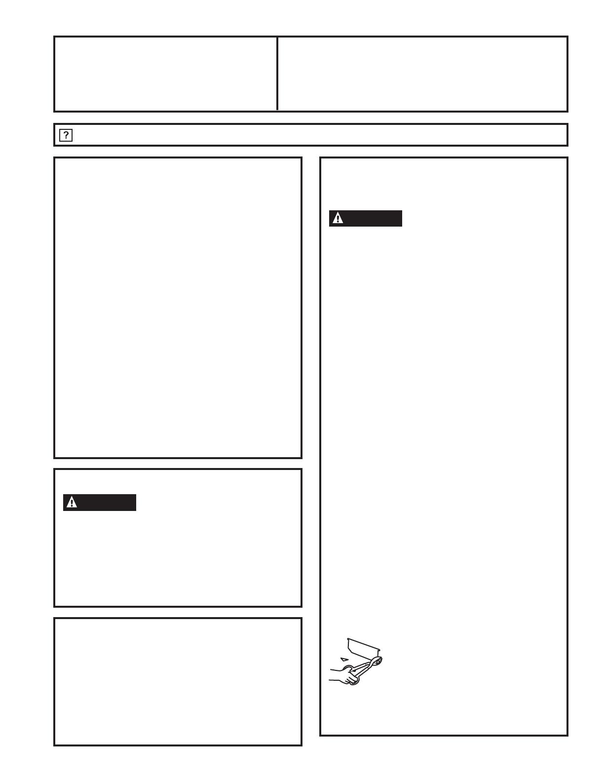
* IMPORTANTE: Si se utiliza un adaptador de
transición de rectangular a circular, las esquinas
inferiores del regulador se deberán cortar para que
coincidan, usando las tijeras para hojalata, a fin
de permitir un movimiento libre del regulador. Las
longitudes equivalentes a las piezas de conductos
están basadas en evaluaciones reales y reflejan
los requisitos para un buen funcionamiento de la
ventilación con cualquier campana.
INSTRUCCIONES DE INSTALACIÓN
49-80760
9
INSTRUCCIONES DE INSTALACIÓN
Instrucciones de instalación
DAÑO – ENVÍO/ INSTALACIÓN
Si la unidad se daña durante el envío, devuelva
la unidad a la tienda donde fue comprada para su
reparación o reemplazo.
Si la unidad es dañada por el cliente, la reparación o
reemplazo es responsabilidad del cliente.
Si la unidad es dañada por el instalador (si no es
el cliente), la reparación o reemplazo deberán ser
realizados a través de un acuerdo entre el cliente y el
instalador.
HERRAMIENTAS NECESARIAS
PIEZAS INCLUIDAS
ESPACIO DE MONTAJE
NOTAS:
• El ancho de la campana puede ser mayor que el ancho
de la cocina o de la superficie de cocción, pero no
puede ser más pequeño.
• Asegúrese de que la cocina o la superficie de cocción
sea instalada de acuerdo con las instrucciones de
instalación del fabricante.
• Si hará que la ventilación de su cocina salga hacia
el exterior, consulte la sección de “Requisitos de la
Tubería” para la preparación de la tubería de escape.
Destornilladores de
punta plana y Phillips
Lápiz
Tijeras
metálicas
(en algunas
aplicaciones)
Taladro eléctrico
Sierra (sable o
cerradura)
Cinta para
conducto
Pinzas
Nivel
Masilla
Cinta métrica
Ficha
hexagonal
de pivote
de ¼”
Linterna
Pelacables
Llave de
tuercas de ¼”
PIEZA CANTIDAD
Filtro de Grasa únicamente
(JV338)
1
Filtro de Carbón únicamente
(JN327, JN328 and RN328)
1
Filtro de Grasa y Filtro de
Carbón (JV24X, JV347, JV348,
JV367 y AV447)
2
Tornillos de Montaje
(Phillips de cabeza alomada
de 8-18” x ¾”)
4
Adaptador del Escape (para
ventilación rect. de 3 ¼” x 10”)
1
Tornillo del Adaptador del
Escape (Phillips con cabeza
alomada o hexagonal de
8-18” x 3/8”)
1
66” o más
desde el
piso hasta
la parte
superior de
la campana
24”, 30” o 36” para
coincidir con el ancho de
la superficie de cocción
Mín.
de 30”
El extremo
inferior del
gabinete debe
estar a una
distancia de 30”
o más desde
la superficie de
cocción.
10
49-80760
Instrucciones de instalación
1
ELIJA LA OPCIÓN DE VENTILACIÓN
Determine la opción de ventilación necesaria para
su instalación y disponible para su modelo entre las
opciones que figuran más abajo.
IMPORTANTE: Si la campana será instalada sin tubería,
con recirculación y no ventilada, no anule ninguna
abertura de ventilación de la campana. Sólo se debe
anular un agujero de la campana para el acceso eléctrico.
A
Escape superior hacia fuera
(conducto vertical – rectangular de 3 ¼” x 10”)
C
Escape trasero hacia fuera
(conducto horizontal – rectangular de 3 ¼” x 10”)
B
Escape superior hacia fuera
(conducto vertical - Redondo de 7”)
D
Recirculación
(no ventilada/ sin conducto)
JV338
JN327
JN328
RN328
JV247
JV248
JV347
JV348
JV367
AV447
JV247
JV248
JV347
JV348
JV367
AV447
JV338 JV338
JV247
JV248
JV347
JV348
JV367
AV447
JV247
JV248
JV347
JV348
JV367
AV447
INSTRUCCIONES DE INSTALACIÓN
49-80760
11
INSTRUCCIONES DE INSTALACIÓN
2
RETIRE EL ADAPTADOR DEL ESCAPE
Si el escape/ ventilación se realizará con una
WXEHUtDUHFWDQJXODUGHó´[Ǝ²RSFLRQDOSDUD
los modelos JV247, JV248, JV338, JV347, JV348,
JV367 y AV447 únicamente:
Retire el adaptador del escape de la parte interna
de la campana. Deje el mismo a un lado con sus
tornillos de montaje.
5
RETIRE LA TAPA DEL CABLEADO
Retire la tapa del cableado de la parte interna de la
campana. Deje la tapa y los tornillos de montaje a un
costado.
6
RETIRE LA ABERTURA DEL CABLEADO
Retire tanto la parte superior o la parte trasera de la
abertura del cableado según sea necesario e instale una
abrazadera con amortiguador de refuerzo aprobada.
7
RETIRE LA ABERTURA DEL CONDUCTO
Si se hará una recirculación, sin conducto ni
ventilación (modelos JN327, JN328 y RN328, y
opcional para JV247, JV248, JV347, JV348, JV367 y
AV447 únicamente), vaya al Paso 11 D y prosiga.
Utilizando un destornillador de punta plana, retire
la abertura del conducto apropiada de la parte
superior o trasera de la campana.
3
RETIRE EL FILTRO
Retire la cinta de embalaje que sostiene el filtro
de grasa metálico en su posición. Presione hacia
abajo sobre el centro del extremo frontal del filtro.
El filtro luego se deslizará de las lengüetas de
retención en la parte trasera.
4
INVIERTA EL DEFLECTOR PARA
INSTALACIONES EN CONDUCTOS
ÚNICAMENTE (modelos JV247, JV248,
JV347, JV348, JV367 y AV447)
Si la campana será recirculada, vaya al siguiente
paso. Retire el deflector de la parte superior de la
campana. Vuelva a instalar el deflector de modo
que el lado corto con la marca “VENTILADO” quede
visible. Este lado largo del deflector debe estar
dentro de la campana.
Adaptador
del escape
rectangular
de 3 ¼”
x 10” y
tornillos
Filtro de grasa metálico
“VENTILADO” está visible
Tapa del
cableado
Abrazadera
con
amortiguador
de refuerzo
Abertura
trasera
Abertura
superior
Abrazadera con
amortiguador de
refuerzo
Descarga vertical
rectangular de 3 ¼” x 10”.
Retire la abertura del
conducto rectangular
superior únicamente.
Descarga vertical redonda
de 7”. Retire la abertura del
conducto circular únicamente.
Descarga horizontal rectangular de 3 ¼” x 10”. Retire la
abertura del conducto rectangular trasero únicamente.
Instrucciones de instalación
12
49-80760
8
PARA INSTALACIÓN DE DESCARGA CON
CONDUCTO RECTANGULAR DE 3 ¼” X
10” ÚNICAMENTE:
Adhiera el adaptador/ regulador de salida sobre
la abertura apropiada (para instalación vertical
u horizontal, dependiendo de la misma) con dos
tornillos del adaptador de salida. Asegúrese de que
el pivote del regulador esté lo más cerca posible del
extremo superior/ inferior de la campana. Retire la
cinta de la solapa del regulador.
10
PARA LOS GABINETES INFERIORES
EMPOTRADOS ÚNICAMENTE
Si los gabinetes cuentan con bordes frontales,
laterales o traseros, haga 2 cuñas de un grosor
mínimo de 3/8” y recorte para que coincida el ancho
de la parte inferior interna del gabinete empotrado.
Adhiera los mismos al hueco de la parte inferior
del gabinete sobre ambos lados. Consulte las
ubicaciones marcadas en el Paso 11.
9
PARA INSTALACIONES DE DESCARGA
CON CONDUCTO VERTICAL REDONDO
DE 7” ÚNICAMENTE.
Incline las orejas de alineación del conducto como
preparación para la adherencia posterior del
conducto de 7”.
Cinta
Extremo
superior/ trasero
Adaptador/ regulador del escape
(posición de descarga vertical)
Pivote
(dependiendo de
la instalación)
Adaptador/ regulador del escape
(posición de descarga horizontal)
Lengüetas de las orejas
de adherencia
Cuñas de madera
(grosor mínimo de 3/8”)
Instrucciones de instalación
INSTRUCCIONES DE INSTALACIÓN
49-80760
13
INSTRUCCIONES DE INSTALACIÓN
Instrucciones de instalación
11
MARQUE LOS AGUJEROS
Seleccione la opción de ventilación que su
instalación requerirá y proceda a dicha sección:
A
Escape superior hacia fuera
(Conducto vertical – Rectangular de 3 ¼” x 10”)
Use el diagrama o la campana como plantilla y
marque las ubicaciones en el gabinete para el
conducto, el cableado eléctrico y las ranuras para
los tornillos de la cerradura.
B
Escape superior hacia fuera
(Conducto vertical – Redondo de 7”)
Use el diagrama o la campana como plantilla y
marque las ubicaciones en el gabinete para el
conducto, el cableado eléctrico y las ranuras para
los tornillos de la cerradura.
12
CORTE LOS AGUJEROS
Corte los agujeros en las ubicaciones marcadas
para el conducto y el cableado eléctrico. Para el
conducto vertical, corte 3/4” adicionales hacia el
frente del gabinete, de modo que pueda mover
el conducto libremente al instalar la campana.
También puede facilitar la instalación cortar un
agujero de 10 ½” en lugar de 10”.
13
PASE LOS CABLES
Pase los cables eléctricos a través de la pared o
del gabinete de acuerdo con el Código Nacional de
Electricidad y los códigos locales aplicables.
NOTA: NO active la corriente hasta haber
completado la instalación.
C
Escape trasero hacia fuera
(conducto horizontal – Rectangular de 3 ¼” x 10”)
Use el diagrama o la campana como plantilla y
marque las ubicaciones en el gabinete para el
conducto, el cableado eléctrico y las ranuras para
los tornillos de la cerradura.
D
Recirculación (sin conducto ni ventilación –
JN327, JN328 y RN328, y opcional en los
modelos JV247, JV248, JV347, JV348, JV367 y
AV447 únicamente)
Use la campana como plantilla y marque las
ubicaciones en el gabinete para el cableado eléctrico
y las ranuras para los tornillos de la cerradura.
Debido a que la campana será recirculada (no
ventilada hacia fuera), no corte ninguna abertura
de la ventilación en la pared o en la parte inferior
del gabinete.
Tornillos para el montaje de la campana (4)
10 ¾” (campana de 24”)
13 ¾” (campana de 30”)
16 ¾” (campana de 36”)
Frente del gabinete
Línea
central
Agujero de acceso
eléctrico (en la parte
inferior del gabinete)
Cuñas de madera (gabinetes
empotrados en la parte
inferior únicamente – las
cuñas deben tener un
mínimo de 3/8” de grosor
y estar cortadas de modo
que calcen en el ancho de
la parte inferior interna del
gabinete empotrado)
Agujero de acceso
para conducto
redondo de 7”
9
5
ø8s
1
3
ø8s
1
1
ø4s
7
3
ø4s
5
3
ø4s
Para inferior
del gabinete
AGUJERO
DE 8” DE
DIÁM.
Tornillos para el montaje de la campana (4)
10 ¾” (campana de 24”)
13 ¾” (campana de 30”)
16 ¾” (campana de 36”)
10 ¾” (campana de 24”)
13 ¾” (campana de 30”)
16 ¾” (campana de 36”)
Frente del gabinete
Línea
central
Agujero de acceso
eléctrico (en la parte
inferior del gabinete)
Cuñas de madera
(gabinetes empotrados
en la parte inferior
únicamente – las cuñas
deben tener un mínimo
de 3/8” de grosor y estar
cortadas de modo que
calcen en el ancho de la
parte inferior interna del
gabinete empotrado)
9
5
ø8s
1
3
ø8s
1
1
ø4s
7
3
ø4s
3
3
ø4s
1
ø2s
5
1
ø4s
5
1
ø4s
Parte inferior del gabinete
Agujero de acceso al
conducto vertical
10 ¾” (campana de 24”)
13 ¾” (campana de 30”)
16 ¾” (campana de 36”)
Cuñas de madera (gabinetes empotrados en la parte inferior
únicamente – las cuñas deben tener un mínimo de 3/8” de grosor y
estar cortadas de modo que calcen en el ancho de la parte inferior
interna del gabinete empotrado)
Frente del gabinete
Línea
central
Agujero de acceso
eléctrico (en la pared)
Tornillos para el montaje
de la campana (4)
Para inferior
del gabinete
10 ¾” (campana de 24”)
13 ¾” (campana de 30”)
16 ¾” (campana de 36”)
1
1
ø4s
1
ø2s
3
3
ø4s
5
1
ø4s
5
1
ø4s
7
3
ø4s
10 ¾” (campana de 24”)
13 ¾” (campana de 30”)
16 ¾” (campana de 36”)
Agujero de acceso al
conducto horizontal
14
49-80760
Instrucciones de instalación
INSTRUCCIONES DE INSTALACIÓN
14
ATORNILLE HASTA LA MITAD
Coloque un tornillo de montaje (del paquete de
herramientas) hasta la mitad en cada centro del
cuello estrecho de las ranuras de las cerraduras
marcados en la parte inferior del gabinete.
17
ASEGURE LA CAMPANA
Deslice la campana nuevamente contra la pared.
Ajuste los tornillos de montaje. Asegúrese de que
las cabezas de los tornillos estén en el cuello
estrecho de la ranura de la cerradura.
NOTA: NO PRESIONE LA PALETA DEL
VENTILADOR. Presionar la paleta podrá hacer que
ésta interfiera con otras partes de la campana.
17
CONECTE LA TUBERÍA A LA CAMPANA
(Sólo para instalaciones con tubería)
En instalaciones con tubería redonda de 7”, adhiera
la tubería de 7” con tornillos para chapa metálica a
través de los agujeros de las orejas de alineación.
Use la cinta para tuberías a fin de hacer que las
juntas queden seguras y herméticas.
16
CABLES DE ALIMENTACIÓN
Levante la campana hasta su posición y alimente
el cableado del hogar a través de la abertura del
cableado.
15
KIT DEL CABLE DE CORRIENTE
OPCIONAL JXHC1
Un Kit de Conexión de Cable de Corriente opcional,
modelo JXHC1, está disponible por un costo
adicional a través de su proveedor de GE para la
instalación utilizando un tomacorriente de pared con
conexión a tierra de 3 patas. Siga las Instrucciones
de Instalación adjuntas con el kit para conectar el
cable de corriente a la campana de la cocina.
NOTA: Si usará el Kit de Cable de Corriente JXHC1
opcional, alimente el cable de corriente a través del
agujero en el gabinete superior mientras eleva la
campana. Enrolle cualquier longitud excesiva del
cable y ajuste con una cinta adecuada o nudo.
Gabinete
7
3
ø4s
Tomacorriente
de pared de 3
patas (si usará
una conexión
con cable)
1
1
ø4s
Agujero de despeje de 1
¾” de diámetro para una
ubicación de suministro de
corriente opcional
C
L
Cerradura (4)
Tornillo de
montaje (4)
Lengüetas de las orejas de adherencia
Conducto redondo de 7”
Cinta para
conducto
49-80760
15
INSTRUCCIONES DE INSTALACIÓN
Instrucciones de instalación
19
INSTALE LA LÁMPARA DE LUZ
NOTA: No se incluye una lámpara de luz con la
campana. Obtenga una localmente. Adquiera e instale
una lámpara de luz incandescente tipo A15 con una
base atornillada común, de no más de 60 watts, o una
luz Fluorescente Compacta (CFL) tipo A17 o T2 con
una base atornillada común, de no más de 13 watts.
NOTA: Use sólo lámparas incandescentes en los
modelos RN328, JN327, JN328 y JV338.
IMPORTANTE: Para la instalación, y las
precauciones de manipulación y descarte, consulte
las instrucciones de embalaje de lámparas
fluorescentes.
Al usar una lámpara de ahorro de energía en su
campana GE, asegúrese de usar:
22
REEMPLACE EL CABLE DE COBRE
23
REEMPLACE EL FILTRO
Asegúrese de que la paleta del ventilador gire
libremente y reemplace el filtro. NOTA: Instale el
filtro de grasa metálico si está conectado con una
tubería o el filtro de carbón si está recirculado.
La instalación está completa. Encienda la corriente
desde el panel de servicio, y controle que el
funcionamiento sea correcto.
LISTA DE CONTROL PARA LA SOLUCIÓN DE
PROBLEMAS
Si la campana parece estar funcionando en alta velocidad
cuando el control no está en la configuración alta, o si la
ventilación parece inadecuada, controle lo siguiente:
Aberturas no retiradas de la campana.
La paleta del regulador no está funcionando.
Flujo de aire reducido debido a que el conducto es
demasiado pequeño o la longitud del conducto es
demasiado extensa.
El conducto está bloqueado.
La pared o la tapa del techo no coinciden con el
tamaño o están restringidas.
Si la campana parece estar produciendo demasiado
ruido:
El ventilador puede estar golpeando el filtro. Apague
el ventilador y retire el filtro. Incline el filtro hacia
abajo levemente desde el centro (en forma de cúpula)
para permitir el despeje del ventilador. Reinstale y
ajuste según sea necesario.
El ventilador no funciona pero las luces sí:
Apague el interruptor del panel del servicio y
bloquee el suministro del servicio a fin de evitar que
la corriente se active en forma accidental. Cuando
el suministro del servicio no pueda ser bloqueado,
ajuste de forma segura un dispositivo de advertencia
visible, tal como una etiqueta, al panel del servicio.
Controle las conexiones de los cables. Consulte la
sección de CONEXIÓN DEL CABLEADO en estas
Instrucciones de Instalación.
20
CUMPLA CON EL CÓDIGO DE ELECTRICIDAD
Complete el cableado eléctrico de acuerdo con el
Código Nacional de Electricidad y los códigos locales.
NOTA: Esta campana deberá estar conectada a
tierra de forma permanente. Conecte el cableado
del hogar (120 VAC) al cableado de la campana.
21
CONECTE EL CABLEADO
Conecte el cable negro del hogar al cable negro de la
campana, el cable blanco del hogar al cable blanco
de la campana y el cable
a tierra del hogar debajo
del tornillo de conexión
a tierra verde. Ajuste de
forma segura la clavija con
amortiguador de refuerzo
al cableado del hogar.
ADVERTENCIA
LA CONEXIÓN INADECUADA
DEL CABLEADO HOGAREÑO DE ALUMINIO A
LAS GUÍAS DE COBRE PUEDEN PRODUCIR UN
PROBLEMA GRAVE. USE SÓLO CONECTORES
DISEÑADOS PARA UNIR EL COBRE CON
EL ALUMINIO Y SIGA EL PROCEDIMIENTO
RECOMENDADO POR EL FABRICANTE DE
FORMA DETENIDA.
GE Long Life Energy
Smart
Spiral
®
T2
Código del Producto: 85383
Descripción
FLE13HT2/2/SW/CD
GE Long Life Energy
Smart
A17
Código del Producto: 47486
Descripción:
FLE11/2/A17XL/CD
Disponibles en
www.gelighting.com
o
Tapa del cableado
Filtro de grasa metálico o filtro de carbón
Tornillo
verde de
conexión
a tierra
16
49-80760
Problema Causas posibles Qué hacer
El Ventilador/ la Luz no
funciona
El fusible puede haberse
quemado o el interruptor
decircuitos puede haber saltado.
Cambie los fusibles o reconfigure el interruptor de
circuitos.
Ruido de flujo de aire muy
elevado o anormal
Tamaño de conducto incorrecto
utilizado en la instalación.
El uso de un conducto más pequeño hará que la
ventilación se reduzca. Minimice la longitud del
conducto y el número de transiciones y codos.
Los
técnicos de GE no pueden corregir este problema
si hay una instalación inadecuada.
El ventilador no hace
circular aire o desplaza
desplaza el aire más
despacio que lo normal y/o
hace ruido de flujo de aire
elevado o anormal
Obstrucciones en el conducto. Verifique que no haya obstrucciones en la ventilación.
Controle que la cubierta de pared o casquete de techo
tengan una hoja o puerta.
El filtro de grasa metálico y el
filtro de carbón (si lo hubiera)
pueden estar sucios.
Asegúrese de que el regulador de tiro se mueva
libremente. Las hojas del regulador de tiro pueden
darse vuelta y no se abrirán por completo cuando esto
suceda. Ajústela con la posición original.
Es posible que el filtro de grasa
metálico y el filtro de carbón (de
estar presentes) estén sucios.
Limpie el filtro de grasa metálico y vuelva a colocar el
filtro de carbón (si lo hubiera). Ver Cuidado y limpieza
de la campana de ventilación.
Insuficiente reposición
(reemplazo) de aire
Se requiere suficiente reposición (reemplazo) de aire
para que los artefactos con salida de aire funcionen
de acuerdo con sus calificaciones energéticas.
Controle los códigos locales de construcción, que
podrán requerir o aconsejar enfáticamente el uso de
reposición de aire. Para acceder soluciones de aire
disponibles, visite GEAppliances.com.
Falla temprana de la
lámpara
El voltaje de la lámpara es
demasiado alto.
Reemplace la misma por una con el voltaje correcto.
CONSEJOS PARA LA SOLUCIÓN DE PROBLEMAS
Consejos para la Solución de Problemas... Antes de solicitar el servicio técnico
¡Ahorre tiempo y dinero! Primero revise los cuadros que aparecen en las siguientes páginas y es posible que no necesite
solicitar reparaciones.
  • Page 1 1
  • Page 2 2
  • Page 3 3
  • Page 4 4
  • Page 5 5
  • Page 6 6
  • Page 7 7
  • Page 8 8
  • Page 9 9
  • Page 10 10
  • Page 11 11
  • Page 12 12
  • Page 13 13
  • Page 14 14
  • Page 15 15
  • Page 16 16
  • Page 17 17
  • Page 18 18
  • Page 19 19
  • Page 20 20
  • Page 21 21
  • Page 22 22
  • Page 23 23
  • Page 24 24
  • Page 25 25
  • Page 26 26
  • Page 27 27
  • Page 28 28
  • Page 29 29
  • Page 30 30
  • Page 31 31
  • Page 32 32

GE AV447FBS El manual del propietario

Categoría
Campanas de cocina
Tipo
El manual del propietario

En otros idiomas