
Installation Manual
Manual de Instalación
English /
Español
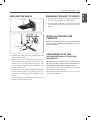
Model/Modelo: 721.7603*
P/N MFL69646001 Rev 00
Sears Brands Management Corporation
Hoffman Estates, IL 60179 U.S.A.
www.kenmore.com
www.sears.com
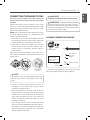
Kenmore Elite®
Gas Range
Estufa de Gas
* = color number, número de color
ESPAÑOL
ENGLISH

TABLE OF CONTENTS
2
TABLE OF CONTENTS
3 IMPORTANT SAFETY INSTRUCTIONS
5 PREPARING FOR INSTALLATION
5 Before You Begin
5 Tools Needed
5 Materials You May Need
6 Dimensions and Clearances
7 Location
7 Gas Pipe and Electrical Outlet Locations
8 INSTALLING THE RANGE
8 Installing the Anti-Tip Device
8 Providing Adequate Gas Supply
9 Connecting the Range to Gas
10 Electrical Connections
10 Sealing the Openings
11 Assembling the Surface Burners
11 Checking Ignition of Surface Burners
12 Adjusting the Surface Burner to the Low Flame(Simmer) Setting
12 Checking Operation of Bake/Broil Burners
12 Adjusting Air Shutter for LP Conversions
13 Leveling the Range
13 Engaging the Anti-Tip Device
13 When all Hookups are Complete
13 Converting to LP Gas

IMPORTANT SAFETY INSTRUCTIONS
3
ENGLISH
IMPORTANT SAFETY INSTRUCTIONS
Read and follow all instructions before using your oven to prevent the risk of fire, electric shock, personal injury, or damage
when using the range. This guide does not cover all possible conditions that may occur. For further assistance contact your
service agent or manufacturer.
This is the safety alert symbol. This symbol alerts you to potential hazards that can cause personal injury to
you and others. All safety messages will follow the safety alert symbol and either the word “WARNING” or
“CAUTION”.
WARNING
This symbol will alert you to hazards or unsafe practices which could cause serious bodily harm or death.
CAUTION
This symbol will alert you to hazards or unsafe practices which could cause bodily injury or property damage.
• If the information in this manual is not followed exactly, a fire or explosion may result causing property damage,
personal injury or death.
WARNING
• DO NOT store or use combustible materials, gasoline or other flammable vapors and liquids in the vicinity of this or any
other appliance.
WHAT TO DO IF YOU SMELL GAS
• DO NOT try to light any appliance.
• DO NOT touch any electrical switch.
• DO NOT use any phone in your building.
• Immediately call your gas supplier from a neighbor’s phone. Follow the gas supplier’s instructions.
• If you cannot reach your gas supplier, call the fire department.
• Installation and service must be performed by a qualified installer, service agency or the gas supplier.
• ALL RANGES CAN TIP
• INJURY TO PERSONS COULD RESULT
• INSTALL ANTI-TIP DEVICES PACKED WITH RANGE
• SEE INSTALLATION INSTRUCTIONS
WARNING
• DO NOT step or sit on the door. Install the anti-tip bracket packed with range.
− The range could be tipped and injury might result from spilled hot liquid, food, or the range itself.
− If the range is pulled away from the wall for cleaning, service, or any other reason, ensure that the anti-tip device is
properly reengaged when the range is pushed back against the wall.
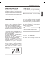
• All ranges can tip and injury could result. To prevent accidental tipping of the range, attach an approved anti-tip
device to the wall. (See “Installing the Anti-Tip Device” in this manual.) To check if the device is installed and engaged
properly, carefully tip the range forward. The Anti-Tip device should engage and prevent the range from tipping over.
If you pull the range out from the wall for any reason, make sure the anti-tip device is engaged when you push the range
back against the wall.

IMPORTANT SAFETY INSTRUCTIONS
4
• NEVER reuse old flexible connectors. The use of old flexible connectors can cause gas leaks and personal injury.
Always use NEW flexible connectors when installing a gas appliance.
• The range must be installed by a qualified installer.
• The range should be electrically grounded in accordance with local codes or, in the absence of local codes, in
accordance with the National Electrical Code (ANSI/NFPA 70, latest edition). In Canada, electrical grounding must
comply with the current CSA C22.1 Canadian Electrical Code Part 1 and/or local codes. See “Electrical Connections”
in this manual.
• Before installing the range on linoleum or any other synthetic floor covering, make sure the floor covering can resist
180°F (82°C) without shrinking, warping or discoloring. Do not install the range over carpeting unless a sheet of 1/4”
thick plywood or similar insulator is placed between the range and carpeting.
• Make sure the wall coverings around the range can resist heat generated by the range up to 200°F (93°C).
• Leak testing of the appliance shall be conducted according to the manufacturer’s instructions.
• Avoid placing cabinets above the range. To minimize the hazard caused by reaching over the open flames of operating
burners, install a ventilation hood over the range that projects forward at least 5” beyond the front of the cabinets.
• The ventilation hood must be constructed of sheet metal not less than 0.0122” thick. Install above the cooktop with
a clearance of not less than 1/4” between the hood and the underside of the combustible material or metal cabinet.
The hood must be at least as wide as the appliance and centered over the appliance.
Clearance between the cooking surface and the ventilation hood surface MUST NEVER BE LESS THAN 24 INCHES.
• EXCEPTION: Installation of a listed microwave oven or cooking appliance over the cooktop shall conform to the
installation instructions packed with that appliance.
• If cabinets are placed above the range, allow a minimum clearance of 30” between the cooking surface and the
bottom of unprotected cabinets.
• If a 30” clearance between cooking surface and overhead combustible material or metal cabinets cannot be
maintained, protect the underside of the cabinets above the cooktop with not less than 1/4” insulating millboard
covered with sheet metal not less than 0.0122” thick. Clearance between the cooking surface and protected cabinets
MUST NEVER BE LESS THAN 24 INCHES.
• The vertical distance from the plane of the cooking surface to the bottom of adjacent overhead cabinets extending
closer than 1” to the plane of the range sides must not be less than 18”. (See the Dimensions and Clearances illustration
in this manual.)
WARNING
• Items of interest to children should not be stored in cabinets above a range or on the backsplash of a range–children
climbing on the range to reach items could be seriously injured.
• DO NOT attempt to operate the oven of this range during a power failure.
CAUTION
IN THE COMMONWEALTH OF MASSACHUSETTS
• This product must be installed by a licensed plumber or gas fitter.
• When using ball type gas shut-off valves, they shall be the T-handle type.
• When using a flexible gas connector, it must not exceed 3 feet in length.

PREPARING FOR INSTALLATION
5
ENGLISH
PREPARING FOR
INSTALLATION
BEFORE YOU BEGIN
Read these instructions completely and carefully.
Installation of this range must conform with local codes, or
in the absence of local codes, with the National Fuel Gas
Code, ANSI Z223.1/NFPA.54, latest edition. In Canada,
installation must conform with the current Natural Gas
Installation Code, CAN/CGAB149.1 or the current Propane
Installation Code, CAN/CGA-B149.2, and with local codes
where applicable. This range has been design-certified by
CSA International according to ANSI Z21.1, latest edition
and Canadian Gas Association according to CAN/CGA-1.1
latest edition.
As with any appliance using gas and generating heat, there
are certain safety precautions you should follow. You will
find these precautions in the important Safety Information
section in your Use & Care Guide. Read them carefully.
• IMPORTANT – Save these instructions for local
electrical inspector’s use.
• IMPORTANT – Observe all governing codes and
ordinances.
Note to Installer: Leave these instructions with the
appliance after installation is completed.
Note to Consumer: Keep the Use & Care Guide and
Installation Instructions for future reference.
NOTE: This appliance must be properly grounded.
• The electrical diagram is in an envelope attached to the
back of the range.
• Skill level – Installation of this appliance requires basic
mechanical skills.
• Proper installation is the responsibility of the installer.
• Product failure due to improper installation is not covered
under the Warranty.
• Remove all tape and packaging.
• Make sure the burners are properly seated and level.
• Take the accessory pack out of the oven and/or drawer.
• Check to be sure that no range parts have come loose
during shipping.
Remove all tape and packing materials before using the
range.
Dispose of all plastic bags after unpacking the range.
Never allow children to play with packing materials.
You can download the Installation Manual and Use & Care
Guide at: http://www.kenmore.com
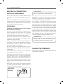
TOOLS NEEDED
Phillips screwdriver
Flat-blade screwdriver
Pencil and ruler
Open-end or
adjustable wrench
Pipe wrench (2)
(one for support)
Level
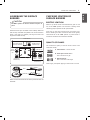
PARTS PROVIDED
Template (1)
(For Anti-Tip Bracket Mounted on
Concrete Floors and Walls)
Anchor Sleeves (4)
Anti-Tip Bracket Kit (1)
Lag Bolts (4)
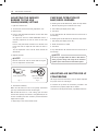
MATERIALS YOU MAY NEED
• Gas line shut-off valve
• Pipe joint sealant that resists action of natural and LP
gases.
• Flexible metal appliance connector (3/4” or 1/2” NPT x
1/2” I.D.)
Never use an old connector when installing a new range.
• Flare union adapter for connection to gas supply line
(3/4” or 1/2” NPT x 1/2” I.D.)
• Flare union adapter for connection to pressure regulator
on range (1/2” NPT x 1/2” I.D.)
• Liquid leak detector or soapy water.
• Lag bolt or 1/2” O.D. sleeve anchor (for concrete floors
only)

PREPARING FOR INSTALLATION
6
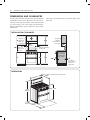
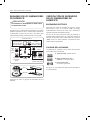
DIMENSIONS AND CLEARANCES
Provide proper clearances between the range and adjacent
combustible surfaces. These dimensions must be met for
safe use of the range. The location of the electrical outlet
and pipe opening (see “GAS PIPE AND ELECTRICAL
OUTLET LOCATIONS”) may be adjusted to meet specific
requirements.
INSTALLATION CLEARANCES
18”
5”
30”
30”
5”
36”
1/4”
13”
0”
Minimum to
cabinets on
either side
of the range
Minimum
clearance to
left wall
Minimum
Minimum clearance
to right wall
To cabinets
below cooktop
and at the
range back
Maximum
depth for
cabinets above
countertops
Front edge of
the range side
panel forward
from cabinet
DIMENSIONS
30”
28
3
/
4
”
47
7
/
16
”
43
5
/
32
”
36” ±
1/4”
Depth with door closed (includes door handle)
Height
Depth with door open.
The range may be placed with 0” clearance (flush) at the
back wall.

PREPARING FOR INSTALLATION
7
ENGLISH
LOCATION
Do not locate the range where it may be subject to strong
drafts. Any openings in the floor or wall behind the range
should be sealed. Make sure the openings around the
base of the range that supply fresh air for combustion and
ventilation are not blocked by carpeting or woodwork.
The range, like many other household units, is heavy and
can be installed on soft floor coverings such as cushioned
vinyl or carpeting. Use care when moving the range on this
type of flooring.
Use a belt when moving the range to prevent damaging
the floor. Or slide the range onto cardboard or plywood to
avoid damaging the floor covering.
This appliance must not be installed with a ventilation
system that blows air downward toward the range.
This type of ventilation system may cause ignition and
combustion problems with the gas cooking appliance
resulting in personal injury or unintended operation.
When the floor covering ends at the front of the range,
the area that the range will be installed on should be built
up with plywood to the same level or higher than the floor
covering. This will allow the range to be moved for cleaning
and servicing, as well as proper air flow to the range.
Also, make sure the floor covering can resist 180°F (82°C).
See the "IMPORTANT SAFETY INSTRUCTIONS" (included in
this manual).
Make sure the wall coverings around the range can resist
the heat generated (up to 200°F/93°C) by the range. See
the "IMPORTANT SAFETY INSTRUCTIONS" (included in this
manual).
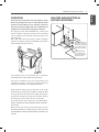
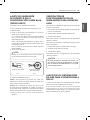
GAS PIPE AND ELECTRICAL
OUTLET LOCATIONS
30
”
Recommended area for
120V outlet on rear wall
and area for through-the-
wall connection of pipe
stub and shut-off valve.
Recommended area
for through-the-floor
connection of pipe stub
and shut-off valve.
2
”
3
”
9
1
/
16
”
11
3
/
32
”
14
5
/
16
”
8
19
/
32
”
2
3
/
8
”

INSTALLING THE RANGE
8
INSTALLING THE RANGE
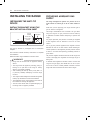
INSTALLING THE ANTI-TIP
DEVICE
INSTALL THE BRACKET USING THE
BRACKET INSTALLATION SHEET
Anti-tip
bracket
Wall plate
Screw must
enter wood or
concrete
The anti-tip bracket is packaged with an installation
template.
The instructions include necessary information to complete
the installation.
Read and follow range installation instruction sheet.
• Range must be secured with an approved anti-tip
device.
• The range could be tipped by standing, sitting or
leaning on an open door if the range or anti-tip
device is not properly installed.
• After installing the anti-tip device, verify that it is
in place by carefully attempting to tilt the range
forward.
• This range has been designed to meet all recognized
industry tip standards for all normal conditions.
• The installation of the anti-tip device must meet all
local codes for securing the appliance.
• The use of this device does not preclude tipping of
the range when not properly installed.
WARNING
PROVIDING ADEQUATE GAS
SUPPLY
The range is designed to operate at a pressure of 5” of
water column on natural gas or 10” of water column on
L P.
Make sure you are supplying your range with the type of
gas for which it is configured.
This range is convertible for use on natural or LP gas. When
using this range on LP gas, conversion must be made by
a qualified LP installer before attempting to operate the
range.
For proper operation, the pressure of natural gas supplied
to the regulator must be between 5” and 13” of water
column.
For LP gas, the pressure supplied to the regulator must be
between 10” and 13” of water column. When checking for
correct operation of the regulator, the inlet pressure must be
at least 1” more than the operating (manifold) pressure as
given above.
The pressure regulator located at the inlet of the range must
remain in the supply line regardless of which type of gas is
being used.
A flexible metal appliance connector used to connect the
range to the gas supply line should have an I.D. of 5/8”
and a max of 5ft. In Canada, flexible connectors must be
single wall metal connectors less than 6 feet in length.

INSTALLING THE RANGE
9
ENGLISH
CONNECTING THE RANGE TO GAS
Shut off the range gas supply valve before removing the
old range and leave it off until the new hook-up has been
completed.
Because hard piping restricts movement of the range,
the use of a CSA International-certified flexible metal
appliance connector should be used unless local codes
require a hard-piped connection.
NEVER reuse an old connector when installing a new range.
To protect against gas leaks, use a qualified pipe joint
sealant on all external threads.
1. Install male 1/2" or 3/4v flare union adapter to the NPT
internal thread of the manual shut-off valve, taking care
to back-up the shut-off valve to keep it from turning.
2. Install male 1/2" flare union adapter to the 1/2" NPT
internal thread at inlet of pressure regulator. Use a
backup wrench on the pressure regulator fitting to
prevent damage.
Make sure the gas pressure regulator valve is open. If it is
shut, remove the rubber O-ring and rotate the lever on the
valve to open it.
Lever’s open
position
Lever’s closed
position
The regulator valve is open when shipped. If the range
does not work, make sure the regulator valve is still
open.
NOTE
3. Connect a flexible metal appliance connector to
the adapter on the range. Position range to permit
connection at the shut-off valve.
4. When all connections have been made, be sure all
range controls are in the OFF position and the pressure
regulator valve is open before turning on the main gas
supply valve. Gas leaks may occur in your system and
result in a dangerous situation. Gas leaks may not be
detected by smell alone.
Check all gas connection joints and fittings for leaks
with a non-corrosive leak detection fluid, then wipe off.
Gas suppliers recommend you purchase and install a UL
approved gas detector. Install and use in accordance
with the installation instructions.
DO NOT USE A FLAME TO CHECK FOR GAS LEAKS.
WARNING
Isolate the range from the gas supply system by
closing its individual shut-off valve during any pressure
testing of the gas supply system at test pressures equal
to or less than 1/2" psig (3.5 kPa).
WARNING
FLEXIBLE CONNECTOR HOOKUP
Installer: Inform the
consumer of the
location of the gas
shut-off valve
1/2
”
or 3/4
”
Gas pipe
Gas shut-off valve
Adapter
Adapter
Pressure regulator
Gas Flow into Range
Flex connector
(6 ft. max.)
If you need to shut off the gas supply to the range, close
the main gas shutoff valve by turning it clockwise.

INSTALLING THE RANGE
10
ELECTRICAL CONNECTIONS
ELECTRICAL REQUIREMENTS
120 Volt, 60 Hertz, properly grounded dedicated circuit
protected by a 15 or 20 Amp circuit breaker, or slow blow
fuse.
If an external electrical source is used, the appliance, when
installed, must be electrically grounded in accordance
with local codes or, in the absence of local codes, with the
National Electrical Code, ANSI/NFPA 70.
GROUNDING
IMPORTANT: FOR PERSONAL SAFETY, THIS APPLIANCE
MUST BE PROPERLY GROUNDED.
The power cord of this appliance is equipped with a
3-prong (grounding) plug which mates with a standard
3-prong grounding wall receptacle to minimize the
possibility of electric shock hazard from this appliance.
The customer should have the wall receptacle and circuit
checked by a qualified electrician to make sure the
receptacle is properly grounded.
Where a standard two-prong wall receptacle is
encountered, it is the personal responsibility and obligation
of the customer to have it replaced with a properly
grounded three-prong wall receptacle.
DO NOT, UNDER ANY CIRCUMSTANCES, CUT OR
REMOVE THE THIRD (GROUND) PRONG FROM THE
POWER CORD.
A word about GFCI’s – GFCI’s are not required or
recommended for gas range receptacles.
Ground Fault Circuit Interrupters (GFCI’s) are devices that
sense leakage of current in a circuit and automatically
switch off power when a threshold leakage level is
detected. These devices must be manually reset by the
consumer. The National Electrical Code requires the use of
GFCI’s in kitchen receptacles installed to serve countertop
surfaces.
Performance of the range will not be affected if operated
on a GFCI-protected circuit but the occasional resetting of
the circuit can become an annoyance.
PREFERRED
METHOD
Ensure proper ground
exists before use
Have the circuit checked by a qualified electrician to
make sure the receptacle is properly grounded.
CAUTION
DO NOT use an adapter plug. Disconnecting the power
cord places undue strain on the adapter and leads to
eventual failure of the adapter ground terminal.
The installation of appliances designed for mobile
home installation must conform with the Manufactured
Home Construction and Safety Standard, Title 24 CFR,
Part 3280 (formerly the Federal Standard for Mobile
Home Construction and Safety, Title 24, HUD, Part 280)
or, when such standard is not applicable, the Standard
for Manufactured Home Installations, latest edition
(Manufactured Home Sites, Communities and Set-Ups), ANSI
A225.1, latest edition, or with local codes. In Canada, mobile
home installation must be in accordance with the current
CAN/CSA Z240/MH Mobile Home Installation Code.
POWER MUST BE DISCONNECTED BEFORE
SERVICING THE APPLIANCE. FAILURE TO DO SO
CAN RESULT IN DEATH OR ELECTRICAL SHOCK.
WARNING
SEALING THE OPENINGS
Seal any openings in the wall and floor after electrical and
gas supplies are completed.

INSTALLING THE RANGE
11
ENGLISH
ASSEMBLING THE SURFACE
BURNERS
DO NOT operate the burners without all parts in
place.
CAUTION
Place the burner caps and heads on the cooktop. Make sure
that the caps and heads are placed in the correct locations.
There is one small, one medium, one large and one extra
large burner head and cap.
Center Burner
(on some models)
Oval (Center) Burner
Head/Cap Assembly
Medium
burner
head and
cap
Large burner
head and cap
Small burner
head and cap
Extra large burner
head and cap
(on some
models)
(on some
models)
Front of range
(on some models)
Medium burner
head and cap
Hole
Electrode
Make sure the hole in the burner head is positioned over the
electrode.
CHECKING IGNITION OF
SURFACE BURNERS
ELECTRIC IGNITION
Select a top burner knob and simultaneously push in and
turn to the “LITE” position. You will hear a clicking sound
indicating proper operation of the spark module.
Once the air has been purged from the supply lines,
burner should ignite within 4 seconds. After burner ignites,
rotate knob out of the “LITE” position. Try each burner in
succession until all burners have been checked.
QUALITY OF FLAMES
The combustion quality of burner flames needs to be
confirmed visually.
A Yellow flames – Call for service.
B Yellow tips on outer cones –
This is normal for LP gas
C Soft blue flames –
This is normal for natural gas
With LP gas, some yellow tipping on outer cones is normal.

INSTALLING THE RANGE
12
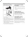
ADJUSTING THE SURFACE
BURNER TO THE LOW
FLAME(SIMMER) SETTING
1. Light all surface burners.
2. Turn the knob on the burner being adjusted to “LO”.
3. Remove knob.
4. Insert a small, flat-blade screwdriver into the valve shaft
as shown in Fig. 1.
On right front valve for model LDG3019ST there is a
secondary adjustment for the low flame for the outer
burners.
Insert a small, flat-blade screwdriver into the hole next
to the valve stem to adjust the outer flame as shown in
Fig. 2.
Turn the adjustment screw until the flame reaches the
desired size.
5. Replace the knob.
Hold the valve shaft with one hand while turning the
screw for adjustment with the other.
NOTE
Center adjustment screw
Fig. 1 Fig. 2
Adjustment screw next
to the valve shaft
6. Test the flame stability.
Test 1: Turn the knob from “HI” to “LO” quickly. If the flame
goes out, increase the flame size and test again.
Test 2: With the burner on a “LO” setting, open and close
the oven door quickly. If the flame is extinguished by the air
currents created by the door movement, increase the flame
height and test again.
7. Repeat steps 1-6 for each surface burner.
CHECKING OPERATION OF
BAKE/BROIL BURNERS
To check ignition of the Bake burner, follow the steps below:
1. Remove all packing from inside the oven cavity.
2. Press "Bake" (the display shows 350).
3. Press Start.
It may take between 30 and 90 seconds for the burner to
start heating.
To check ignition of the Broil burner, follow the steps below:
1. Press "Broil" (The display shows "Hi").
2. Make sure the door is closed.
3. Press Start.
It may take between 30 and 90 seconds for the burner to
start heating.
Do not try and light either the bake or broil burners
during a power outage. The range has an electrical
ignition system and cannot be used without power.
NOTE
ADJUSTING AIR SHUTTER FOR LP
CONVERSIONS
The range comes from the factory with air shutters adjusted
for proper air flow for natural gas.
If converted to LP, follow the instructions provided in the
conversion kit to properly adjust the air shutters.
LP conversion must be performed by a qualified technician.

INSTALLING THE RANGE
13
ENGLISH
LEVELING THE RANGE
Spirit level
Leg leveler
Raise
range
Lower
range
1. Install the oven shelves in the oven and locate the range
where it will be installed.
2. Check if the range is level by placing a spirit level or
a cup, partially filled with water, on one of the oven
shelves. If using a spirit level, take two readings– with
the level placed diagonally first in one direction – ①
and then the other – ②.
3. Remove the lower door. See the “CARE AND CLEANING
OF THE RANGE” section in the owner's manual. The
front and rear leveling legs can be adjusted from the
bottom.
4. Use an open-end or adjustable wrench to adjust the
leveling legs until the range is level.
ENGAGING THE ANTI-TIP DEVICE
1. Slide the range against the wall, making sure the back
leg slides into and engages the anti-tip bracket.
2. Check for proper installation by grasping the front edge
of the cooktop and carefully attempting to tilt the range
forward.
WHEN ALL HOOKUPS ARE
COMPLETE
Make sure all controls are left in the off position. Make
sure the flow of combustion and ventilation air to the
range is unblocked.
CONVERTING TO LP GAS
(OR CONVERTING BACK TO NATURAL
GAS FROM LP)
This range leaves the factory set for use with natural
gas. The conversion to LP gas must be performed by a
qualified LP gas installer when converting to LP gas.
The conversion instructions and LP orifices can be found
attached to the range on the back.
Keep these instructions and the orifices in case you want to
convert back to natural gas.

MEMO
14
MEMO

ÍNDICE
15
ESPAÑOL
ÍNDICE
16 INSTRUCCIONES IMPORTANTES DE SEGURIDAD
18 PREPARACIÓN PARA LA INSTALACIÓN
18 Antes de comenzar
18 Herramientas necesarias
18 Materiales que puede necesitar
19 Dimensiones y espacios
20 Ubicación
20 Ubicaciones de tubería de gas y tomacorriente eléctrico
21 INSTALACIÓN DE LA ESTUFA
21 Instalación del soporte anti vuelco
21 Cómo brindar el suministro adecuado de gas
22 Conexión de la estufa al gas
23 Conexiones eléctricas
23 Sellado de aberturas
24 Ensamble de los quemadores de superficie
24 Verificación de encendido de los quemadores de superficie
25 Ajuste del quemador de superficie en la configuración llama baja (fuego lento)
25 Verificación de funcionamiento de los quemadores para hornear/asar
25 Ajuste de los obturadores de aire para conversiones a gas LP
26 Nivelación de la estufa
26 Colocación del soporte anti vuelco
26 Cuando todas las conexiones están hechas
26 Convirtiendo a gas LP

INSTRUCCIONES IMPORTANTES DE SEGURIDAD
16
INSTRUCCIONES IMPORTANTES DE SEGURIDAD
Lea estas instrucciones completamente y cuidadosamente. Una instalación, ajuste, alteración, servicio o mantenimiento
inapropiado puede causar lesiones o daños en propiedad. Consulte este manual. Para ayuda o información adicional,
consulte a un instalador calificado, agencia de servicio, fabricante (vendedor) o al proveedor del servicio de gas.
Este es el símbolo de alerta de seguridad. Este símbolo le alertará sobre riesgos potenciales que pueden matar o
lesionar a usted y a otras personas. Todos los mensajes de seguridad seguirán al símbolo de alerta de seguridad
con la palabra “ADVERTENCIA” o “PRECAUCIÓN”.
ADVERTENCIA
Este símbolo le alertará sobre riesgos o prácticas inseguras que pueden causar lesiones corporales graves o la muerte.
PRECAUCIÓN
Este símbolo le alertará sobre riesgos o prácticas inseguras que pueden causar lesiones corporales graves o daños en
propiedad.
• Si la información en este manual no se sigue al pie de la letra, puede resultar en incendio o explosión causando daños en
propiedad, lesiones personales o muerte.
ADVERTENCIA
• NO almacenar ni usar materiales combustibles, gasolina u otros vapores o líquidos inflamables en la cercanía de este o cualquier
otro aparato.
QUÉ HACER SI HUELE A GAS
• NO intente encender ningún aparato.
• NO toque ningún interruptor eléctrico.
• NO use ningún teléfono en su edificio.
• Llame inmediatamente a su proveedor de gas desde el teléfono de un vecino. Siga las instrucciones del proveedor de gas.
• Si no puede comunicarse con su proveedor de gas, llame al departamento de bomberos.
• La instalación y el servicio deben ser realizados por un instalador calificado, agencia de servicio o proveedor de gas.
• TODAS LAS ESTUFAS PUEDEN VOLCARSE.
• PUEDE RESULTAR EN LESIONES PERSONALES.
• INSTALE EL SOPORTE ANTI VUELCO INCLUIDO CON LA ESTUFA.
• VER INSTRUCCIONES DE INSTALACIÓN.
ADVERTENCIA
• NO pisar ni sentarse en la puerta. Instale el soporte anti vuelco incluido con la estufa.
− La estufa se puede volcar y causar lesiones por líquido o alimentos calientes derramados o por la propia estufa.
− Si la estufa es separada de la pared para limpiarla, darle servicio o por otra razón, asegúrese que el soporte anti vuelco esté
puesto apropiadamente al momento de poner de nuevo la estufa contra la pared.
• Todas las estufas se pueden volcar y causar lesiones. Para prevenir una volcadura accidental de la estufa, coloque un soporte anti
vuelco autorizado a la pared. (Ver “INSTALACIÓN DEL SOPORTE ANTI VUELCO” en este manual). Para verificar que el soporte
está instalado y puesto apropiadamente, incline con cuidado la estufa hacia adelante. El soporte anti vuelco debe impedir que la
estufa se vuelque. Si separa la estufa de la pared por alguna razón, asegúrese que el soporte anti vuelco esté puesto al empujar
la estufa de nuevo contra la pared.

INSTRUCCIONES IMPORTANTES DE SEGURIDAD
17
ESPAÑOL
• NUNCA reutilice conectores flexibles viejos. Usar conectores flexibles viejos pueda causar fugas de gas y lesiones personales.
Siempre utilice conectores flexibles NUEVOS al instalar un aparato de gas.
• Su estufa debe ser instalada por un instalador calificado.
• Su estufa debe estar conectada a tierra conforme a los códigos locales o, en ausencia de dichos códigos conforme al Código
Nacional Eléctrico (ANSI/NFPA 70, última edición). En Canadá, la conexión a tierra debe cumplir con el Código Eléctrico
Canadiense CSA C22.1 Parte 1 y/o códigos locales. Ver “CONEXIONES ELÉCTRICAS” en este manual.
• Antes de instalar su estufa sobre linóleo u otro revestimiento sintético de piso, asegúrese que el revestimiento de piso resista
82˚C(180˚F)sinencogerse,pandearseodecolorarse.Noinstalelaestufasobrealfombraamenosquecoloqueunahojade
madera laminada de 1/4” de espesor o aislante similar entre la estufa y la alfombra.
• Asegúrese que los revestimientos de pared alrededor de la estufa sean resistentes al calor generado por la estufa de hasta
93˚C(200˚F).
• La prueba de fugas del aparato debe ser realizada conforme a las instrucciones del fabricante.
• Evite colocar gabinetes arriba de la estufa. Para minimizar el riesgo de alcanzar flamas abiertas de los quemadores
encendidos, instale una campana de ventilación sobre la estufa que se proyecte al frente al menos 5” más allá del frente
de los gabinetes.
• La campana de ventilación debe ser de hoja metálica con un mínimo de 0.0122” de espesor. Instale arriba de la parrilla con
un espacio mínimo de 1/4” entre la campana y el lado inferior del gabinete metálico o material combustible.
La campana debe estar centrada y ser mínimo del mismo ancho que el aparato. El espacio entre la superficie para cocinar
y la superficie de la campana NUNCA DEBE SER MENOR DE 24 PULGADAS.
• EXCEPCIÓN: La instalación de un horno de microondas o aparato de cocina arriba de la parrilla debe ser conforme a las
instrucciones de instalación incluidas en ese aparato.
• En caso de colocar gabinetes arriba de la estufa, deje un espacio mínimo de 30” entre la superficie para cocinar y la parte
inferior de los gabinetes desprotegidos.
En caso de no poder mantener un espacio de 30” entre la superficie para cocinar y el gabinete metálico o material
combustible arriba, proteja el lado inferior del gabinete de arriba de la campana con una cartulina aislante de 1/4”
mínimo cubierta con hoja metálica de 0.0122” de espesor mínimo. El espacio entre la superficie para cocinar y los
gabinetes protegidos NUNCA DEBE SER MENOR A 24 PULGADAS.
• La distancia vertical desde el plano de la superficie para cocinar hasta el lado inferior de los gabinetes adyacentes superiores
extendiéndose a menos de 1” hacia el plano de los lados de la estufa no debe ser menor de 18”. (Ver la ilustración de
Dimensiones y Espacios en este manual).
ADVERTENCIA
• Los artículos de interés para los niños no deben almacenarse en gabinetes arriba de la estufa ni en la salpicadera de la
estufa, los niños que suben a la estufa para alcanzar estos artículos pueden lesionarse gravemente.
• NO intente operar el horno de esta estufa durante una falla de energía.
PRECAUCIÓN
EN EL ESTADO DE MASSACHUSETTS
• Este producto debe ser instalado por un plomero autorizado o con regulador de gas.
• Al usar válvulas de cierre de gas tipo bola, deben ser de tipo de manivela T.
• Al usar un conector de gas flexible, no debe exceder 3 pies de longitud.

PREPARACIÓN PARA LA INSTALACIÓN
18
PREPARACIÓN PARA LA
INSTALACIÓN
ANTES DE COMENZAR
Lea estas instrucciones con cuidado y completamente.
La instalación de esta estufa debe ser conforme a los códigos
locales, o en ausencia los mismos, conforme al Código
Nacional de Gas Combustible, ANSI Z223.1/NFPA.54, última
edición. En Canadá, la instalación debe ser conforme al
Código de Instalaciones de Gas Natural, CAN/CGAB149.1
o conforme al Código de Instalaciones de Gas Propano
vigente, CAN/CGA-B149.2, y conforme a los códigos locales
correspondientes. Esta estufa está certificada en su diseño por
CSA International conforme a ANSI Z21.1, última edición y por
la Asociación Canadiense de Gas, conforme a CAN/CGA-1.1
última edición.
Al igual que con cualquier aparato que utiliza gas y genera
calor, existen ciertas precauciones de seguridad que debe
seguir. Encontrará estas precauciones en la sección de
Información importante de seguridad en su Guía de Uso y de
Cuidados. Lea estas precauciones cuidadosamente.
• IMPORTANTE
– Guarde estas instrucciones para uso
del inspector de electricidad local.
• IMPORTANTE
– Observe todos los códigos y
ordenanzas regulatorias.
Nota para el instalador: Deje estas instrucciones junto al
aparato después de terminar la instalación.
Nota para el consumidor: Guarde la Guía de Uso y de
Cuidados y las Instrucciones de instalación para futura referencia.
NOTA: Este aparato debe conectarse a tierra
apropiadamente.
• El diagramado eléctrico se encuentra en un sobre adherido a
la parte posterior de la estufa.
• Nivel de habilidades - la instalación de este aparato requiere
habilidades mecánicas básicas.
• Una instalación apropiada es responsabilidad del instalador.
• La falla del producto a causa de una instalación inapropiada,
no es cubierta por la Garantía.
• Quite toda la cinta y material de empaque.
• Asegúrese que los quemadores estén asentados y nivelados
apropiadamente.
• Saque el paquete de accesorios del horno y/o cajón.
• Verifique y asegúrese que no se hayan soltado piezas de la
estufa durante el envío.
Quite toda la cinta y material de empaque antes de usar
la estufa. Deseche todas las bolsas de plástico después de
desempacar la estufa. Nunca permita que los niños jueguen
con materiales de empaque.
Puede descargar el manual de instalación en:
http://www.kenmore.com
HERRAMIENTAS NECESARIAS
Desarmador Phillips
Desarmador plano
Pencil and ruler
Llave inglesa o
ajustable
Llave para tubos (2)
(una para soporte)
Nivel
PIEZAS PROVISTAS
Plantilla (1)
(Solamente cuando se instala la ménsula de anti-
volcadura en pisos de concreto)
Manguitos de anclaje (4)
Juego de ménsula
anti-volcadura (1)
Pernos de fijación (4)
MATERIALES QUE PUEDE
NECESITAR
• Válvula de cierre de línea de gas
• Sello de junta de tubería resistente a la acción del gas natural
y gas LP
• Conector metálico flexible de aparato (3/4” o 1/2” NPT x
1/2” D.I.)
Nunca use un conector viejo al instalar una estufa nueva.
• Adaptador de unión acampanada para conexión a línea de
suministro de gas (3/4” o 1/2” NPT x 1/2” D.I.)
• Adaptador de unión acampanada para conexión a regulador
de presión en estufa (1/2” NPT x 1/2” D.I.)
• Detector de fugas líquido o agua con jabón.
• Tornillo para madera o ancla de camisa de 1/2” D.E. (para
pisos de concreto únicamente)

PREPARACIÓN PARA LA INSTALACIÓN
19
ESPAÑOL
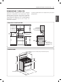
Proporcione espacios apropiados entre la estufa y superficies
adyacentes combustibles. Estas dimensiones deben
cumplirse para un uso seguro de su estufa. La ubicación
del tomacorriente eléctrico y abertura de tubería (ver
“UBICACIONES DE TUBERÍA DE GAS Y TOMACORRIENTE
ELÉCTRICO”) se puede ajustar para cumplir con
requerimientos específicos.
La estufa se puede colocar con un espacio de 0” (al ras) de la
pared posterior.
DIMENSIONES Y ESPACIOS
ESPACIOS DE INSTALACIÓN
18”
5”
30”
30”
5”
36”
1/4”
13”
0”
Mínimo para
gabinetes de
cada lado
de la estufa
Espacio mínimo
a la pared
izquierda
Minimum
Espacio mínimo a la
pared derecha
A los gabinetes
debajo de la parrilla
y en el lado posterior
de la estufa
Profundidad
máxima para
gabinetes arriba de
los mostradores
Borde frontal
del lado de la
estufa adelante
del gabinete
DIMENSIONES
30”
28
3
/
4
”
47
7
/
16
”
43
5
/
32
”
36” ±
1/4”
Profundidad con puerta cerrada (incluye manivela de la puerta)
Altura
Profundidad con puerta abierta.

PREPARACIÓN PARA LA INSTALACIÓN
20
UBICACIÓN
No coloque su estufa donde pueda estar expuesta a
fuertes corrientes de aire. Cualquier abertura en el piso
o pared detrás de la estufa debe sellarse. Asegúrese
que las aberturas alrededor de la base de la estufa que
suministran aire fresco para combustión y ventilación no
estén bloqueadas por alfombras o estructuras de madera.
Su estufa, como muchos otros aparatos del hogar, es pesada
y puede instalarse sobre revestimientos de piso suaves como
por ejemplo vinilo acojinado o alfombra. Tenga cuidado al
momento de mover la estufa en este tipo de pisos.
Utilice una correa al mover la estufa, para evitar dañar el
piso. O deslice la estufa sobre un cartón o madera enchapada
para evitar dañar el revestimiento del piso.
Este equipo no se debe de instalar con un sistema de
ventilación que circule aire hacia la parte baja trasera de
la estufa. Este tipo de sistema de ventilación puede causar
problemas de ignición y combustión en el equipo de gas,
pudiendo resultar en lesiones y funcionamiento inadecuado.
Cuando el revestimiento de piso termina al frente de la estufa,
el área donde la estufa va a ser instalada debe estar hecha
de madera laminada al mismo nivel o más arriba que el
revestimiento de piso. Esto permitirá mover la estufa para
limpieza y servicio, así como para un flujo de aire apropiado
para la estufa.
También, asegúrese que el revestimiento de pared
sea resistente a 82˚C (180˚F). Ver “INSTRUCCIONES DE
SEGURIDAD DE LA INSTALACIÓN” (incluidas en este manual).
Asegúrese que los revestimientos de pared alrededor de su
estufa resistan el calor generado(hasta 93˚C/200˚F) por
la estufa. Ver “INSTRUCCIONES DE SEGURIDAD DE LA
INSTALACIÓN” (incluidas en este manual).
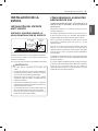
UBICACIONES DE TUBERÍA
DE GAS Y TOMACORRIENTE
ELÉCTRICO
30
”
Área recomendada para
tomacorriente de 120V en
la pared posterior y área
para conexión a través
de la pared de tubo de
escape y válvula de cierre.
Área recomendada para
conexión a través del
piso del tubo de escape
y válvula de cierre.
2
”
3
”
9
1
/
16
”
11
3
/
32
”
14
5
/
16
”
8
19
/
32
”
2
3
/
8
”

INSTALACIÓN DE LA ESTUFA
21
ESPAÑOL
INSTALACIÓN DE LA
ESTUFA
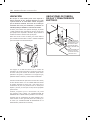
INSTALACIÓN DEL SOPORTE
ANTI VUELCO
INSTALE EL SOPORTE USANDO LA
HOJA DE INSTALACIÓN DE SOPORTE
Soporte Anti
vuelco
Placa de
pared
El tornillo debe
entrar en madera
o concreto
El soporte anti vuelco viene con una plantilla de instalación.
Las instrucciones incluyen la información necesaria para
completar la instalación.
Lea y siga la hoja de instrucciones de instalación de la estufa.
• La estufa debe ser asegurada con un soporte anti
vuelco.
• La estufa se puede volcar al estar parada, asentada o
inclinada en una puerta abierta si la estufa o el soporte
anti vuelco no está instalado apropiadamente.
• Después de instalar el soporte anti vuelco, verifique
que esté bien puesto al intentar con cuidado inclinar la
estufa hacia adelante.
• Esta estufa está diseñada para cumplir con todos los
estándares de inclinación reconocidos en la industria en
todas las condiciones normales.
• La instalación del soporte anti vuelco debe cumplir con
todos los códigos locales para asegurar el aparato.
• El uso de este soporte no impide la volcadura de la
estufa cuando no está bien instalado.
ADVERTENCIA
CÓMO BRINDAR EL SUMINISTRO
ADECUADO DE GAS
Su estufa está diseñada para operar a una presión de 5” de
columna de agua en gas natural o de 10” de columna de
agua en gas LP.
Asegúrese de suministrar a su estufa el tipo de gas para el
cual está configurada.
Esta estufa es convertible para usarse con gas natural o gas LP.
Al usar esta estufa con gas LP, la conversión debe hacerla un
instalador calificado LP antes de intentar operar la estufa.
Para una operación apropiada, la presión del gas natural
suministrado al regulador debe estar entre 5” y 13” de
columna de agua.
Para gas LP, la presión suministrada al regulador debe estar
entre 10” y 13” de columna de agua. Al verificar que el
regulador funcione correctamente, la presión de la toma debe
ser de al menos 1” mayor a la presión operativa (distribuidor)
arriba indicada.
El regulador de presión ubicado en la toma de la estufa debe
permanecer en la línea de suministro independientemente del
tipo de gas utilizado.
Un conector metálico flexible de aparato usado para conectar
la estufa a la línea de suministro de gas debe tener un Diámetro
Interno de 5/8” y un máximo de 5 pies. En Canadá, los
conectores flexibles deben ser conectores metálicos de pared
sencillos de menos de 6 pies de longitud.

INSTALACIÓN DE LA ESTUFA
22
CONEXIÓN DE LA ESTUFA AL GAS
Cierre el suministro de gas de la estufa antes de quitar la estufa
vieja y manténgalo cerrado hasta terminar la conexión nueva.
Debido a que la tubería dura restringe el movimiento de la estufa,
el uso de un conector metálico flexible de aparatos certificado
por CSA International debe ser usado a menos que los códigos
locales requieran el uso de una conexión de tubería dura.
NUNCA reutilice un conector viejo al instalar una estufa nueva.
Para protegerse contra fugas de gas, use un sellador de junta de
tubería calificado en todas las roscas externas.
1. Instale un adaptador de unión acampanada macho de 1/2”
o 3/4” a la rosca NPT interna de la válvula de cierre manual,
cuidando de dar soporte a la válvula de cierre para evitar que
gire.
2. Instale un adaptador de unión acampanada de 1/2” a la rosca
NPT interna de 1/2” en la toma del regulador de presión. Use
una llave de soporte en el regulador de presión para evitar
daños.
Asegúrese de que la válvula del regulador de presión de gas se
encuentre abierta. Si está cerrada, retire el anillo de goma y gire
la palanca de la válvula para abrirla.
Posición abierta de
la palanca
Posición cerrada
de la palanca
El regulador esta en posición abierta desde fabrica. Si
la estufa no funciona , asegúrese que el regulador de la
válvula este en posición abierta.
NOTA
3. Conecte un conector metálico flexible de aparato al
adaptador en la estufa. Coloque la estufa de manera que
permita la conexión con la válvula de cierre.
4. Asegúrese de que la válvula del regulador de presión de gas
se encuentre abierta. Si está cerrada, retire el anillo de goma y
gire la palanca de la válvula para abrirla.
Revise las uniones y adaptadores de conexión de gas para
detectar fugas con un líquido detector de fugas anticorrosivo
y luego limpie.
Los proveedores de gas recomiendan que compre e instale un
detector de gas aprobado por UL. Instale y use conforme a las
instrucciones de instalación.
NO UTILICE FLAMAS PARA REVISAR FUGAS DE GAS.
ADVERTENCIA
Aísle la estufa del sistema de suministro de gas al cerrar
su válvula de cierre independiente durante cualquier
prueba de presión del sistema de suministro de gas con
presiones de prueba iguales a o menores a 1/2” psi
(3.5 kPa).
ADVERTENCIA
CONEXIÓN DEL CONECTOR FLEXIBLE
Instalador: informe
al consumidor de
la ubicación de la
válvula de cierre de
gas.
Tubería de gas de
1/2
”
ó 3/4
”
Válvula de cierre
de gas
Adaptador
Adaptador
Regulador de presión
Flujo de gas a la estufa
Conector flexible
(6 pies máximo)
Si necesita cortar el suministro de gas a la estufa, cierre la
válvula de gas principal girándola a favor de las manecillas.

INSTALACIÓN DE LA ESTUFA
23
ESPAÑOL
CONEXIONES ELÉCTRICAS
REQUERIMIENTOS ELÉCTRICOS
Circuito dedicado de 120 Volt, 60 Hertz, conectado a tierra
apropiadamente protegido por un interruptor de circuito de 15
o 20 Amp., o fusible de fundido lento.
Si se utiliza una fuente eléctrica externa, cuando se instala el
electrodoméstico se debe contar con una conexión a tierra que
cumpla los códigos locales o, en ausencia de estos, según lo
establecido en el Código Eléctrico Nacional, ANSI/NFPA 70.
CONEXIÓN A TIERRA
IMPORTANTE: POR SEGURIDAD PERSONAL, ESTE APARATO
DEBE ESTAR CONECTADO A TIERRA APROPIADAMENTE.
El cable de energía de este aparato está equipado con
un enchufe de 3 clavijas (para tierra) que enchufa con un
tomacorriente de pared con conexión a tierra estándar para
minimizar el riesgo de choque eléctrico de este aparato.
El cliente debe solicitar que el tomacorriente de pared y
el circuito sean verificados por un electricista calificado
para asegurar que el tomacorriente está conectado a tierra
apropiadamente.
Si se encuentra con un tomacorriente de dos clavijas estándar,
es responsabilidad y obligación personal del cliente pedir que
lo reemplacen con un tomacorriente de pared de tres clavijas
conectado a tierra apropiadamente.
BAJO NINGUNA CIRCUNSTANCIA, NO CORTE LA TERCERA
CLAVIJA (TIERRA) DEL CABLE DE ENERGÍA.
Acerca de GFCI - Los GFCI no son requeridos ni
recomendados para tomacorrientes de estufas de gas.
Los interruptores de circuito de falla de tierra (GFCI) son
dispositivos que detectan fuga de corriente en un circuito
y automáticamente cortan la energía al detectar un nivel
de fuga de umbral. Estos dispositivos deben reajustarse
manualmente por el usuario. El Código Eléctrico Nacional
requiere el uso de GFCI en tomacorrientes de estufa instalados
para servicio a superficies de mostradores. El rendimiento
de la estufa no se verá afectado si funciona en un circuito
protegido con GFCI, pero la necesidad de restablecer el
circuito puede resultar molesta.
MÉTODO
PREFERIBLE
Asegúrese que exista
una conexión a tierra
apropiada antes de
usarlo.
El cliente debe solicitar que un electricista calificado
verifique el circuito para asegurarse de que el
receptáculo tenga la conexión a tierra adecuada.
PRECAUCIÓN
NO utilice un enchufe adaptador. Desconectar el cable de
alimentación genera tensión indebida en el adaptador y
genera una falla eventual en el terminal a tierra del
adaptador.
La instalación de aparatos diseñados para instalación de
casas móviles debe cumplir con la Norma de Construcción y
Seguridad de Casas Fabricadas, Título 24 CFR, Parte 3280
(antes la Norma Federal para Construcción y Seguridad de
Casas Móviles, Título 24, HUD, Parte 280) o, cuando dicha
norma no aplique, la Norma para Instalaciones de Casas
Fabricadas, última edición (Sitios, Comunidades e Instalaciones
de Casas Fabricadas), ANSI A225.1, última edición, o con los
códigos locales. En Canadá, la instalación de casas móviles
debe conformar con el Código de Instalación de Casas
Móviles CAN/CSA Z240/MH vigente.
DEBE DESCONECTAR LA ENERGÍA ANTES DE DAR
SERVICIO AL APARATO. DE NO HACER ESTO PUEDE
RESULTAR EN MUERTE O CHOQUE ELÉCTRICO.
ADVERTENCIA
SELLADO DE ABERTURAS
Selle cualquier abertura en la pared y piso después de
terminar los suministros eléctricos y de gas.

INSTALACIÓN DE LA ESTUFA
24
ENSAMBLE DE LOS QUEMADORES
DE SUPERFICIE
NO ENCIENDA LOS QUEMADORES SIN TENER TODAS
LAS PIEZAS EN SU LUGAR.
PRECAUCIÓN
Coloque las tapas y cabezas de los quemadores en la parrilla.
Asegúrese que todas las tapas y cabezas estén colocadas en
sus ubicaciones correctas. Hay una tapa y una cabeza para
cada quemador pequeño, mediano, grande y extra grande.
Quemador central
(en algunos modelos)
Ensamble de tapa y
cabeza de quemador
(central) ovalado
Tapa y
cabeza
del
quemador
mediano
Tapa y cabeza
del quemador
grande
Tapa y cabeza
del quemador
pequeño
Tapa y cabeza del
quemador extra grande
(en algunos
modelos)
(en algunos
modelos)
Frente de la
estufa
(en algunos
modelos)
Tapa y cabeza de
quemador mediano
Hoyo
Electrodo
Asegúrese de meter el agujero del quemador sobre el
electrodo.
VERIFICACIÓN DE ENCENDIDO
DE LOS QUEMADORES DE
SUPERFICIE
ENCENDIDO ELÉCTRICO
Seleccione una perilla de quemador de parrilla y empuje
hacia adentro y gire a la posición “LITE” (encender)
simultáneamente. Escuchará un sonido “clic” indicando la
operación apropiada del módulo de chispa.
Una vez que se purga el aire de las líneas de suministro, el
quemador debe encender dentro de 4 segundos. Después de
encender el quemador, gire la perilla fuera de la posición
“LITE”. Intente con cada quemador sucesivamente hasta
verificar todos los quemadores.
CALIDAD DE LAS FLAMAS
La calidad de la combustión de las Ilamas del quemador
precisa determinarse visualmente.
A Llamas amarillas – Solicite servicio.
B Puntas amarillas en los conos
exteriores – Es normal en gas LP.
C Llamas azules claras –
Es normal en gas natural.
Con gas LP, es normal que haya algunas puntas amarillas en
los conos exteriores.

INSTALACIÓN DE LA ESTUFA
25
ESPAÑOL
AJUSTE DEL QUEMADOR
DE SUPERFICIE EN LA
CONFIGURACIÓN LLAMA BAJA
(FUEGO LENTO)
1. Encienda todos los quemadores de superficie.
2. Gire la perilla del quemador que está ajustando a “LO”.
3. Quite la perilla.
4. Inserte un desarmador plano delgado en el eje de la
válvula como se muestra en la Fig. 1.
En la válvula frontal derecha para el modelo LDG3019ST
hay un ajuste secundario para flama baja para los
quemadores exteriores.
Inserte a desarmador plano delgado en el agujero junto a
la espiga de la válvula para ajustar la flama exterior como
se muestra en la Fig. 2.
Gire el tornillo de ajuste hasta que la flama alcance el
tamaño deseado.
5. Vuelva a poner la perilla.
Sostenga el eje de la válvula con una mano mientras
gira el tornillo para ajustarlo con la otra mano.
NOTA
Tornillo de ajuste central
Fig. 1 Fig. 2
Tornillo de ajuste junto
al eje de la válvula
6. Pruebe la estabilidad de la flama.
Prueba 1: Gire la perilla de la posición “HI” hacia “LO”
rápidamente. Si la llama se apaga, aumente el tamaño de la
flama y haga la prueba nuevamente.
Prueba 2: con el quemador en posición “LO”, abra y cierre
la puerta del horno rápidamente. Si la flama se apaga por
las corrientes de aire creadas por el movimiento de la puerta,
aumente la altura de la llama y haga la prueba nuevamente.
7. Repita los pasos del 1 al 6 para cada quemador de
superficie.
VERIFICACIÓN DE
FUNCIONAMIENTO DE LOS
QUEMADORES PARA HORNEAR/
ASAR
Para verificar el encendido del quemador de horneado, siga
los pasos a continuación:
1. Para verificar el encendido del quemador de horneado, siga
los pasos a continuación:
2. Presione "Bake" (hornear) la pantalla muestra 350.
3. Presione “Start” (iniciar).
Puede tomar entre 30 y 90 segundos para que el quemador
comience a calentar.
Para verificar el encendido del quemador de asado, siga los
pasos a continuación:
1. Presione "Broil" (asar). La pantalla muestra "Hi" (alto).
2. Asegúrese que la puerta esté cerrada.
3. Presione “Start” (iniciar).
Puede tomar entre 30 y 90 segundos para que el quemador
comience a calentar.
No intente encender los quemadores de hornear o de
asar durante una falla de energía eléctrica. La estufa
tiene un sistema de encendido eléctrico y no se puede
usar sin energía eléctrica.
NOTA
AJUSTE DE LOS OBTURADORES
DE AIRE PARA CONVERSIONES A
GAS LP
La estufa viene de fábrica con compuertas de aire ajustadas
para un flujo de aire apropiado para gas natural.
Si se convierte la estufa a gas LP, siga las instrucciones
proporcionadas en el juego de conversión para ajustar
correctamente las compuertas de aire. La conversión a gas LP
debe ser realizada por un técnico calificado.

INSTALACIÓN DE LA ESTUFA
26
NIVELACIÓN DE LA ESTUFA
Nivel de agua
Nivelador de pata
Elevar
estufa
Bajar
estufa
1. Instale los estantes del horno en el horno y coloque la estufa
donde va a ser instalada.
2. Verifique si la estufa está nivelada al colocar un nivel de
agua o una taza, parcialmente llena de agua, en uno de
los estantes del horno. Si usa un nivel de agua, tome dos
lecturas, primero con el nivel colocado diagonalmente en
una dirección – ① y luego la otra – ②.
3. Quite la puerta inferior. Ver la sección “CUIDADO
Y LIMPIEZA DE LA ESTUFA” en la Guía de Uso y de
Cuidados. Las patas frontales y traseras de nivelación se
pueden ajustar en el lado inferior.
4. Use una llave inglesa abierta o ajustable para ajustar las
patas de nivelación hasta que la estufa quede nivelada.
COLOCACIÓN DEL SOPORTE
ANTI VUELCO
1. Deslice la estufa contra la pared y asegúrese de que la
pata trasera se deslice y enganche en el soporte anti
vuelco.
2. Verifique la instalación adecuada al sujetar el borde
frontal de la placa de cocción e intente inclinar la estufa
hacia adelante.
CUANDO TODAS LAS
CONEXIONES ESTÁN HECHAS
Asegúrese que todos los controles se queden en posición de
apagado. Asegúrese que el flujo de aire de combustión y
ventilación para la estufa no esté bloqueado.
CONVIRTIENDO A GAS LP
(O CONVERTIR DE NUEVO A GAS
NATURAL DESDE GAS LP)
Esta estufa está ajustada de fábrica para usarla con gas
natural. La conversión a gas LP debe ser realizada por un
técnico calificado en gas LP al momento de convertirla a gas
L P.
Las instrucciones de conversión y orificios para gas LP se
pueden encontrar adjuntas a la estufa en el lado posterior.
Conserve estas instrucciones y los orificios en caso que desee
convertir de nuevo a gas natural.

MEMO
27
ESPAÑOL
MEMO

1-844-553-6667
In Canada 1-800-469-4663
Sears Parts & Repair Service Center
1-800-488-1222 1-800-469-4663
1-800-827-6655
1-888-SU-HOGAR
®
1-800-LE-FOYER
MC
1-800-361-6665
-
 1
1
-
 2
2
-
 3
3
-
 4
4
-
 5
5
-
 6
6
-
 7
7
-
 8
8
-
 9
9
-
 10
10
-
 11
11
-
 12
12
-
 13
13
-
 14
14
-
 15
15
-
 16
16
-
 17
17
-
 18
18
-
 19
19
-
 20
20
-
 21
21
-
 22
22
-
 23
23
-
 24
24
-
 25
25
-
 26
26
-
 27
27
-
 28
28


