Tannoy CMS 403DCE Guía de inicio rápido
- Categoría
- Juguetes
- Tipo
- Guía de inicio rápido

Quick Start Guide
CMS 3.0 Series
CMS803DC BM/PI/Q / CMS803 PI BACKCAN
8" Full Range Ceiling Loudspeaker with Dual Concentric Driver
CMS603DC BM/PI / CMS603ICT BM/PI/LS / CMS603 PI BACKCAN
6" Full Range Ceiling Loudspeaker with Dual Concentric or ICT Driver
CMS503DC BM/PI/LP / CMS503ICT BM/PI/LP / CMS503 PI BACKCAN
5" Full Range Ceiling Loudspeaker with Dual Concentric or ICT Driver
CMS403DCE / CMS403ICTE
4" Full Range Ceiling Loudspeaker with Dual Concentric or ICT Driver and adjustable “eyeball” design
V 1.0

2 CMS 3.0 Series Quick Start Guide 3
Las terminales marcadas con este símbolo
transportan corriente eléctrica de
magnitud suciente como para constituir
un riesgo de descarga eléctrica. Utilice solo cables de
altavoz profesionales y de alta calidad con conectores
TS de 6,3 mm o de bayoneta prejados. Cualquier otra
instalación o modicación debe ser realizada únicamente
por un técnico cualicado.
Este símbolo, siempre que aparece,
leadvierte de la presencia de voltaje
peligroso sin aislar dentro de la caja;
estevoltaje puede ser suciente para constituir un riesgo
dedescarga.
Este símbolo, siempre que aparece,
leadvierte sobre instrucciones operativas
y de mantenimiento que aparecen en la
documentación adjunta. Por favor, lea el manual.
Atención
Para reducir el riesgo de descarga
eléctrica, no quite la tapa (o la parte
posterior). No hay piezas en el interior del equipo que
puedan ser reparadas por el usuario. Si es necesario,
póngase en contacto con personal cualicado.
Atención
Para reducir el riesgo de incendio o
descarga eléctrica, no exponga este
aparato a la lluvia, humedad o alguna otra fuente que
pueda salpicar o derramar algún líquido sobre el aparato.
Nocoloque ningún tipo de recipiente para líquidos sobre
el aparato.
Atención
Las instrucciones de servicio deben
llevarlas a cabo exclusivamente personal
cualicado. Para evitar el riesgo de una descarga eléctrica,
no realice reparaciones que no se encuentren descritas
en el manual de operaciones. Lasreparaciones deben ser
realizadas exclusivamente por personalcualicado.
1. Lea las instrucciones.
2. Conserve estas instrucciones.
3. Preste atención a todas las advertencias.
4. Siga todas las instrucciones.
5. No use este aparato cerca del agua.
6. Limpie este aparato con un paño seco.
7. No bloquee las aberturas de ventilación. Instale el
equipo de acuerdo con las instrucciones del fabricante.
8. No instale este equipo cerca de fuentes de calor
tales como radiadores, acumuladores de calor, estufas u
otros aparatos (incluyendo amplicadores) que puedan
producir calor.
9. No elimine o deshabilite nunca la conexión a tierra
del aparato o del cable de alimentación de corriente.
Unenchufe polarizado tiene dos polos, uno de los cuales
tiene un contacto más ancho que el otro. Una clavija con
puesta a tierra dispone de tres contactos: dos polos y la
puesta a tierra. El contacto ancho y el tercer contacto,
respectivamente, son los que garantizan una mayor
seguridad. Si el enchufe suministrado con el equipo no
concuerda con la toma de corriente, consulte con un
electricista para cambiar la toma de corriente obsoleta.
10. Coloque el cable de suministro de energía de manera
que no pueda ser pisado y que esté protegido de objetos
alados. Asegúrese de que el cable de suministro de
energía esté protegido, especialmente en la zona de la
clavija y en el punto donde sale del aparato.
11. Use únicamente los dispositivos o accesorios
especicados por el fabricante.
12. Use únicamente la
carretilla, plataforma,
trípode, soporte o mesa
especicados por el
fabricante o suministrados
junto con el equipo.
Altransportar el equipo,
tenga cuidado para evitar
daños y caídas al tropezar con algún obstáculo.
13. Desenchufe el equipo durante tormentas o si no va a
utilizarlo durante un periodo largo.
14. Confíe las reparaciones únicamente a servicios
técnicos cualicados. La unidad requiere mantenimiento
siempre que haya sufrido algún daño, si el cable de
suministro de energía o el enchufe presentaran daños,
sehubiera derramado un líquido o hubieran caído objetos
dentro del equipo, si el aparato hubiera estado expuesto
a la humedad o la lluvia, si ha dejado de funcionar de
manera normal o si ha sufrido algún golpe o caída.
15. Al conectar la unidad a la toma de corriente eléctrica
asegúrese de que la conexión disponga de una unión
atierra.
16. Si el enchufe o conector de red sirve como único
medio de desconexión, éste debe ser accesiblefácilmente.
17. Cómo debe deshacerse de
este aparato: Este símbolo indica
que este aparato no debe ser
tratado como basura orgánica,
según lo indicado en la Directiva
WEEE (2012/19/EU) y a las
normativas aplicables en su país.
En lugar de ello deberá llevarlo al punto limpio más
cercano para el reciclaje de sus elementos eléctricos/
electrónicos (EEE). Al hacer esto estará ayudando a
prevenir las posibles consecuencias negativas para el
medio ambiente y la salud que podrían ser provocadas
por una gestión inadecuada de este tipo de aparatos.
Además, el reciclaje de materiales ayudará a conservar
los recursos naturales. Para más información acerca del
reciclaje de este aparato, póngase en contacto con el
Ayuntamiento de su ciudad o con el punto limpio local.
18. No instale esta unidad en un espacio muy reducido,
tal como encastrada en una librería o similar.
19. No coloque objetos con llama, como una vela
encendida, sobre este aparato.
20. Tenga presentes todas las advertencias relativas
al reciclaje y correcta eliminación de las pilas. Las pilas
deben ser siempre eliminadas en un punto limpio y nunca
con el resto de la basura orgánica.
21. Puede usar este aparato en lugares con climas
tropicales y moderados que soporten temperaturas de
hasta 45°C.
Music Tribe no admite ningún tipo de responsabilidad
por cualquier daño o pérdida que pudiera sufrir
cualquier persona por conar total o parcialmente en
la descripciones, fotografías o armaciones contenidas
en este documento. Las especicaciones técnicas,
imágenes y otras informaciones contenidas en este
documento están sujetas a modicaciones sin previo
aviso. Todas las marcas comerciales que aparecen
aquí son propiedad de sus respectivos dueños. Midas,
Klark Teknik, Lab Gruppen, Lake, Tannoy, Turbosound,
TC Electronic, TC Helicon, Behringer, Bugera, Oberheim,
Auratone, Aston Microphones y Coolaudio son marcas
comerciales o marcas registradas de Music Tribe
Global Brands Ltd. © Music Tribe Global Brands Ltd.
2021 Reservados todos los derechos.
Si quiere conocer los detalles y condiciones aplicables
de la garantía así como información adicional sobre la
Garantía limitada de Music Tribe, consulte online toda la
información en la web musictribe.com/warranty.
Instrucciones de
seguridad
NEGACIÓN LEGAL
GARANTÍA LIMITADA
Important Safety
Instructions
LEGAL DISCLAIMER
LIMITED WARRANTY
Terminals marked with this symbol carry
electrical current of sucient magnitude
to constitute risk of electric shock.
Use only high-quality professional speaker cables with
¼" TS or twist-locking plugs pre-installed. Allother
installation or modication should be performed only
by qualiedpersonnel.
This symbol, wherever it appears,
alertsyou to the presence of uninsulated
dangerous voltage inside the
enclosure-voltage that may be sucient to constitute a
risk ofshock.
This symbol, wherever it appears,
alertsyou to important operating and
maintenance instructions in the
accompanying literature. Please read the manual.
Caution
To reduce the risk of electric shock, donot
remove the top cover (or the rear section).
No user serviceable parts inside. Refer servicing to
qualied personnel.
Caution
To reduce the risk of re or electric shock,
do not expose this appliance to rain and
moisture. The apparatus shall not be exposed to dripping
or splashing liquids and no objects lled with liquids,
suchas vases, shall be placed on the apparatus.
Caution
These service instructions are for use
by qualied service personnel only.
Toreduce the risk of electric shock do not perform any
servicing other than that contained in the operation
instructions. Repairs have to be performed by qualied
servicepersonnel.
1. Read these instructions.
2. Keep these instructions.
3. Heed all warnings.
4. Follow all instructions.
5. Do not use this apparatus near water.
6. Clean only with dry cloth.
7. Do not block any ventilation openings. Install in
accordance with the manufacturer’s instructions.
8. Do not install near any heat sources such as
radiators, heat registers, stoves, or other apparatus
(including ampliers) that produce heat.
9. Do not defeat the safety purpose of the polarized
or grounding-type plug. A polarized plug has two blades
with one wider than the other. A grounding-type plug
has two blades and a third grounding prong. The wide
blade or the third prong are provided for your safety. Ifthe
provided plug does not t into your outlet, consult an
electrician for replacement of the obsolete outlet.
10. Protect the power cord from being walked on or
pinched particularly at plugs, convenience receptacles,
and the point where they exit from the apparatus.
11. Use only attachments/accessories specied by
themanufacturer.
12. Use only with the
cart, stand, tripod, bracket,
or table specied by the
manufacturer, orsold with
the apparatus. When a cart
is used, use caution when
moving the cart/apparatus
combination to avoid
injury from tip-over.
13. Unplug this apparatus during lightning storms or
when unused for long periods of time.
14. Refer all servicing to qualied service personnel.
Servicing is required when the apparatus has been
damaged in any way, such as power supply cord or plug
is damaged, liquid has been spilled or objects have fallen
into the apparatus, the apparatus has been exposed
to rain or moisture, does not operate normally, or has
beendropped.
15. The apparatus shall be connected to a MAINS socket
outlet with a protective earthing connection.
16. Where the MAINS plug or an appliance coupler is
used as the disconnect device, the disconnect device shall
remain readily operable.
17. Correct disposal of this
product: This symbol indicates
that this product must not be
disposed of with household
waste, according to the WEEE
Directive (2012/19/EU) and
your national law. This product
should be taken to a collection center licensed for the
recycling of waste electrical and electronic equipment
(EEE). The mishandling of this type of waste could have
a possible negative impact on the environment and
human health due to potentially hazardous substances
that are generally associated with EEE. At the same time,
your cooperation in the correct disposal of this product
will contribute to the ecient use of natural resources.
For more information about where you can take your
waste equipment for recycling, please contact your local
city oce, or your household waste collection service.
18. Do not install in a conned space, such as a book
case or similar unit.
19. Do not place naked ame sources, such as lighted
candles, on the apparatus.
20. Please keep the environmental aspects of battery
disposal in mind. Batteries must be disposed-of at a
battery collection point.
21.
This apparatus may be used in tropical and moderate
climates up to 45°C.
Music Tribe accepts no liability for any loss which may
be suered by any person who relies either wholly or in
part upon any description, photograph, or statement
contained herein. Technical specications, appearances
and other information are subject to change without
notice. All trademarks are the property of their
respective owners. Midas, Klark Teknik, Lab Gruppen,
Lake, Tannoy, Turbosound, TC Electronic, TC Helicon,
Behringer, Bugera, Oberheim, Auratone, Aston
Microphones and Coolaudio are trademarks or registered
trademarks of Music Tribe Global Brands Ltd. © Music
Tribe Global Brands Ltd. 2021 All rights reserved.
For the applicable warranty terms and conditions
and additional information regarding Music Tribe’s
Limited Warranty, please see complete details online at
musictribe.com/warranty.

4 CMS 3.0 Series Quick Start Guide 5
Vorsicht
Die mit dem Symbol markierten
Anschlüsse führen so viel Spannung,
dassdie Gefahr eines Stromschlags besteht.
Verwenden Sie nur hochwertige, professionelle
Lautsprecherkabel mit vorinstallierten 6,35 mm
MONO-Klinkensteckern oder Lautsprecherstecker
mit Drehverriegelung. Alle anderen Installationen
oder Modikationen sollten nur von qualiziertem
Fachpersonal ausgeführt werden.
Achtung
Um eine Gefährdung durch Stromschlag
auszuschließen, darf die Geräteabdeckung
bzw. Geräterückwand nicht abgenommen werden.
ImInnern des Geräts benden sich keine vom Benutzer
reparierbaren Teile. Reparaturarbeiten dürfen nur von
qualiziertem Personal ausgeführt werden.
Achtung
Um eine Gefährdung durch Feuer bzw.
Stromschlag auszuschließen, darf dieses
Gerät weder Regen oder Feuchtigkeit ausgesetzt werden
noch sollten Spritzwasser oder tropfende Flüssigkeiten
in das Gerät gelangen können. Stellen Sie keine mit
Flüssigkeit gefüllten Gegenstände, wie z. B. Vasen,
aufdasGerät.
Achtung
Die Service-Hinweise sind nur durch
qualiziertes Personal zu befolgen.
Umeine Gefährdung durch Stromschlag zu vermeiden,
führen Sie bitte keinerlei Reparaturen an dem Gerät
durch, die nicht in der Bedienungsanleitung beschrieben
sind. Reparaturen sind nur von qualiziertem
Fachpersonaldurchzuführen.
1. Lesen Sie diese Hinweise.
2. Bewahren Sie diese Hinweise auf.
3. Beachten Sie alle Warnhinweise.
4. Befolgen Sie alle Bedienungshinweise.
5. Betreiben Sie das Gerät nicht in der Nähe vonWasser.
6. Reinigen Sie das Gerät mit einem trockenen Tuch.
7. Blockieren Sie nicht die Belüftungsschlitze. Beachten
Sie beim Einbau des Gerätes die Herstellerhinweise.
8. Stellen Sie das Gerät nicht in der Nähe von
Wärmequellen auf. Solche Wärmequellen sind z. B.
Heizkörper, Herde oder andere Wärme erzeugende Geräte
(auch Verstärker).
9. Entfernen Sie in keinem Fall die
Sicherheitsvorrichtung von Zweipol- oder geerdeten
Steckern. Ein Zweipolstecker hat zwei unterschiedlich
breite Steckkontakte. Ein geerdeter Stecker hat zwei
Steckkontakte und einen dritten Erdungskontakt.
Derbreitere Steckkontakt oder der zusätzliche
Erdungskontakt dient Ihrer Sicherheit. Falls das
mitgelieferte Steckerformat nicht zu Ihrer Steckdose
passt, wenden Sie sich bitte an einen Elektriker, damit die
Steckdose entsprechend ausgetauscht wird.
10. Verlegen Sie das Netzkabel so, dass es vor
Tritten und scharfen Kanten geschützt ist und nicht
beschädigt werden kann. Achten Sie bitte insbesondere
im Bereich der Stecker, Verlängerungskabel und an
der Stelle, an der das Netzkabel das Gerät verlässt,
aufausreichendenSchutz.
11. Das Gerät muss jederzeit mit intaktem Schutzleiter
an das Stromnetz angeschlossen sein.
12. Sollte der Hauptnetzstecker oder eine
Gerätesteckdose die Funktionseinheit zum Abschalten
sein, muss diese immer zugänglich sein.
13. Verwenden Sie nur Zusatzgeräte/Zubehörteile,
dielaut Hersteller geeignet sind.
14. Verwenden
Sie nur Wagen,
Standvorrichtungen,
Stative, Halter oder Tische,
die vom Hersteller benannt
oder im Lieferumfang
des Geräts enthalten
sind. Falls Sie einen
Wagen benutzen, seien Sie vorsichtig beim Bewegen
der Wagen- Gerätkombination, umVerletzungen durch
Stolpern zuvermeiden.
15. Ziehen Sie den Netzstecker bei Gewitter oder wenn
Sie das Gerät längere Zeit nicht benutzen.
16. Lassen Sie alle Wartungsarbeiten nur von
qualiziertem Service-Personal ausführen. EineWartung
ist notwendig, wenn das Gerät in irgendeiner Weise
beschädigt wurde (z. B. Beschädigung des Netzkabels oder
Steckers), Gegenstände oder Flüssigkeit in das Geräteinnere
gelangt sind, das Gerät Regen oder Feuchtigkeit ausgesetzt
wurde, das Gerät nicht ordnungsgemäß funktioniert oder
auf den Boden gefallen ist.
17. Korrekte Entsorgung
dieses Produkts: Dieses
Symbol weist darauf hin, das
Produkt entsprechend der
WEEE Direktive (2012/19/EU)
und der jeweiligen nationalen
Gesetze nicht zusammen mit
Ihren Haushaltsabfällen zu entsorgen. DiesesProdukt
sollte bei einer autorisierten Sammelstelle für
Recycling elektrischer und elektronischer Geräte (EEE)
abgegeben werden. Wegen bedenklicher Substanzen,
diegenerell mit elektrischen und elektronischen Geräten
in Verbindung stehen, könnte eine unsachgemäße
Behandlung dieser Abfallart eine negative Auswirkung
auf Umwelt und Gesundheit haben. Gleichzeitig
gewährleistet Ihr Beitrag zur richtigen Entsorgung dieses
Produkts die eektive Nutzung natürlicher Ressourcen.
Fürweitere Informationen zur Entsorgung Ihrer Geräte
bei einer Recycling-Stelle nehmen Sie bitte Kontakt zum
zuständigen städtischen Büro, Entsorgungsamt oder zu
Ihrem Haushaltsabfallentsorgerauf.
18. Installieren Sie das Gerät nicht in einer beengten
Umgebung, zum Beispiel Bücherregal oder ähnliches.
19. Stellen Sie keine Gegenstände mit oenen
Flammen, etwa brennende Kerzen, auf das Gerät.
20. Beachten Sie bei der Entsorgung von Batterien
den Umweltschutz-Aspekt. Batterien müssen bei einer
Batterie-Sammelstelle entsorgt werden.
21. Dieses Gerät ist in tropischen und gemäßigten
Klimazonen bis 45° C einsetzbar.
Music Tribe übernimmt keine Haftung für Verluste,
die Personen entstanden sind, die sich ganz oder
teilweise auf hier enthaltene Beschreibungen,
Fotos oder Aussagen verlassen haben. Technische Daten,
Erscheinungsbild und andere Informationen können
ohne vorherige Ankündigung geändert werden. Alle
Warenzeichen sind Eigentum der jeweiligen Inhaber.
Midas, Klark Teknik, Lab Gruppen, Lake, Tannoy,
Turbosound, TC Electronic, TC Helicon, Behringer, Bugera,
Oberheim, Auratone, Aston Microphones und Coolaudio
sind Warenzeichen oder eingetragene Warenzeichen
der Music Tribe Global Brands Ltd. © Music Tribe Global
Brands Ltd. 2021 Alle Rechte vorbehalten.
Die geltenden Garantiebedingungen und zusätzliche
Informationen bezüglich der von Music Tribe gewährten
beschränkten Garantie nden Sie online unter
musictribe.com/warranty.
Les points repérés par ce symbole portent
une tension électrique susante pour
constituer un risque d’électrocution.
Utilisez uniquement des câbles d’enceintes professionnels
de haute qualité avec ches Jack mono 6,35 mm ou ches
à verrouillages déjà installées. Touteautre installation ou
modication doit être eectuée uniquement par un
personnel qualié.
Ce symbole avertit de la présence d’une
tension dangereuse et non isolée à
l’intérieur de l’appareil - elle peut
provoquer des chocs électriques.
Attention
Ce symbol signale les consignes
d’utilisation et d’entre ! Tien importantes
dans la documentation fournie. Lisez les consignes de
sécurité du manuel d’utilisation de l’appareil.
Attention
Pour éviter tout risque de choc électrique,
ne pas ouvrir le capot de l’appareil ni
démonter le panneau arrière. L’intérieur de l’appareil
ne possède aucun élément réparable par l’utilisateur.
Laissertoute réparation à un professionnel qualié.
Attention
Pour réduire les risques de feu et de choc
électrique, n’exposez pas cet appareil à la
pluie, à la moisissure, aux gouttes ou aux éclaboussures.
Ne posez pas de récipient contenant un liquide sur
l’appareil (un vase par exemple).
Attention
Ces consignes de sécurité et d’entretien
sont destinées à un personnel qualié.
Pouréviter tout risque de choc électrique, n’eectuez
aucune réparation sur l’appareil qui ne soit décrite par le
manuel d’utilisation. Les éventuelles réparations doivent
être eectuées uniquement par un technicien spécialisé.
1. Lisez ces consignes.
2. Conservez ces consignes.
3. Respectez tous les avertissements.
4. Respectez toutes les consignes d’utilisation.
5. N’utilisez jamais l’appareil à proximité d’un liquide.
6. Nettoyez l’appareil avec un chion sec.
7. Veillez à ne pas empêcher la bonne ventilation
de l’appareil via ses ouïes de ventilation. Respectezles
consignes du fabricant concernant l’installation
del’appareil.
8. Ne placez pas l’appareil à proximité d’une source
de chaleur telle qu’un chauage, une cuisinière ou tout
appareil dégageant de la chaleur (y compris un ampli
depuissance).
9. Ne supprimez jamais la sécurité des prises bipolaires
ou des prises terre. Les prises bipolaires possèdent deux
contacts de largeur diérente. Leplus large est le contact
de sécurité. Les prises terre possèdent deux contacts plus
une mise à la terre servant de sécurité. Si la prise du bloc
d’alimentation ou du cordon d’ali-mentation fourni ne
correspond pas à celles de votre installation électrique,
faites appel à un électricien pour eectuer le changement
de prise.
10. Installez le cordon d’alimentation de telle façon
que personne ne puisse marcher dessus et qu’il soit
protégé d’arêtes coupantes. Assurez-vous que le cordon
d’alimentation est sufsamment protégé, notamment au
niveau de sa prise électrique et de l’endroit où il est relié à
l’appareil; cela est également valable pour une éventuelle
rallonge électrique.
11. Utilisez exclusivement des accessoires et des
appareils supplémentaires recommandés par lefabricant.
12. Utilisez
exclusivement des
chariots, des diables,
desprésentoirs, despieds
et des surfaces de
travail recommandés
par le fabricant ou
livrés avec le produit.
Déplacezprécautionneusement tout chariot ou diable
chargé pour éviter d’éventuelles blessures en cas dechute.
13. Débranchez l’appareil de la tension secteur en cas
d’orage ou si l’appareil reste inutilisé pendant une longue
période de temps.
14. Les travaux d’entretien de l’appareil doivent
être eectués uniquement par du personnel qualié.
Aucunentretien n’est nécessaire sauf si l’appareil est
endommagé de quelque façon que ce soit (dommagessur
le cordon d’alimentation ou la prise par exemple), siun
liquide ou un objet a pénétré à l’intérieur du châssis, si
l’appareil a été exposé à la pluie ou à l’humidité, s’il ne
fonctionne pas correctement ou à la suite d’une chute.
15. L’appareil doit être connecté à une prise secteur
dotée d’une protection par mise à la terre.
16. La prise électrique ou la prise IEC de tout appareil
dénué de bouton marche/arrêt doit rester accessible
enpermanence.
17. Mise au rebut appropriée de
ce produit: Ce symbole indique
qu’en accord avec la directive DEEE
(2012/19/EU) et les lois en vigueur
dans votre pays, ce produit ne
doit pas être jeté avec les déchets
ménagers. Ce produit doit être
déposé dans un point de collecte agréé pour le recyclage
des déchets d’équipements électriques et électroniques
(EEE). Une mauvaise manipulation de ce type de déchets
pourrait avoir un impact négatif sur l’environnement
et la santé à cause des substances potentiellement
dangereuses généralement associées à ces équipements.
En même temps, votre coopération dans la mise au
rebut de ce produit contribuera à l’utilisation ecace
des ressources naturelles. Pour plus d’informations
sur l’endroit où vous pouvez déposer vos déchets
d’équipements pour le recyclage, veuillez contacter votre
mairie ou votre centre local de collecte des déchets.
18. N’installez pas l’appareil dans un espace conné tel
qu’une bibliothèque ou meuble similaire.
19. Ne placez jamais d’objets enammés, tels que des
bougies allumées, sur l’appareil.
20. Gardez à l’esprit l’impact environnemental lorsque
vous mettez des piles au rebus. Les piles usées doivent
être déposées dans un point de collecte adapté.
21. Cet appareil peut être utilisé sous un climat tropical
ou modéré avec des températures de 45°C maximum.
Music Tribe ne peut être tenu pour responsable
pour toute perte pouvant être subie par toute
personne se ant en partie ou en totalité à toute
description, photographie ou armation contenue
dans ce document. Les caractéristiques, l’apparence
et d’autres informations peuvent faire l’objet de
modications sans notication. Toutes les marques
appartiennent à leurs propriétaires respectifs. Midas,
Klark Teknik, Lab Gruppen, Lake, Tannoy, Turbosound,
TC Electronic, TC Helicon, Behringer, Bugera, Oberheim,
Auratone, Aston Microphones et Coolaudio sont
des marques ou marques déposées de Music Tribe
Global Brands Ltd. © Music Tribe Global Brands Ltd.
2021 Tous droits réservés.
Pour connaître les termes et conditions de garantie
applicables, ainsi que les informations supplémentaires
et détaillées sur la Garantie Limitée de Music Tribe,
consultez le site Internet musictribe.com/warranty.
Consignes de sécurité
DÉNI LÉGAL
Wichtige
Sicherheitshinweise
HAFTUNGSAUSSCHLUSS
BESCHRÄNKTE GARANTIE
GARANTIE LIMITÉE

6 CMS 3.0 Series Quick Start Guide 7
Attenzione
I terminali contrassegnati da questo
simbolo conducono una corrente elettrica
di magnitudine suciente a costituire un rischio di scossa
elettrica. Utilizzare solo cavi per altoparlanti professionali
di alta qualità con jack sbilanciati da 6,35mm. o connettori
con blocco a rotazione. Tutte le altre installazioni o
modiche devono essere eseguite esclusivamente da
personale qualicato.
Attenzione
Questo simbolo, ovunque appaia, avverte
della presenza di una tensione pericolosa
non isolata all'interno dello chassis, tensione che può
essere suciente per costituire un rischio di scossa
elettrica.
Attenzione
Questo simbolo, ovunque appaia, segnala
importanti istruzioni operative e di
manutenzione nella documentazione allegata. Si invita a
leggere il manuale.
Attenzione
Per ridurre il rischio di scosse elettriche,
non rimuovere il coperchio superiore
(o la sezione posteriore). All'interno non ci sono parti
riparabili dall'utente. Per la manutenzione rivolgersi a
personale qualicato.
Attenzione
Per ridurre il rischio di incendi o scosse
elettriche, non esporre questo apparecchio
a pioggia e umidità. L'apparecchio non deve essere
esposto a gocciolio o schizzi di liquidi e nessun oggetto
contenente liquidi, come vasi, deve essere collocato
sull'apparecchio.
Attenzione
Queste istruzioni di servizio sono destinate
esclusivamente a personale qualicato.
Per ridurre il rischio di scosse elettriche non eseguire
interventi di manutenzione diversi da quelli contenuti
nel manuale di istruzioni. Le riparazioni devono essere
eseguite da personale di assistenza qualicato.
1. Leggere queste istruzioni.
2. Conservare queste istruzioni.
3. Prestare attenzione a tutti gli avvisi.
4. Applicare tutte le istruzioni.
5. Non utilizzare questo dispositivo vicino l'acqua.
6. Pulire esclusivamente con un panno asciutto.
7. Non bloccare le aperture di ventilazione. Installare in
conformità con le istruzioni del produttore.
8. Non installare vicino a fonti di calore come
radiatori, termoregolatori, stufe o altri apparecchi
(inclusi amplicatori) che producono calore.
9. Non escludere la sicurezza fornita dalla spina
polarizzata o con messa a terra. Una spina polarizzata ha
due lame, una più larga dell'altra. Una spina con messa a
terra ha due lame e un terzo polo di messa a terra. La lama
larga o il terzo polo sono forniti per la vostra sicurezza.
Se la spina fornita non si adatta alla presa, consultare un
elettricista per la sostituzione della presa obsoleta.
10. Proteggere il cavo di alimentazione dal calpestio
o essere schiacciato in particolare alle spine, prese di
corrente e il punto in cui esce dall'apparecchio.
11. Utilizzare esclusivamente dispositivi/accessori
specicati dal produttore.
12. Utilizzare solo
carrelli, supporti, treppiedi,
stae o tavoli indicati dal
produttore o venduti con
l'apparecchio. Utilizzando
un carrello, prestare
attenzione quando si
sposta la combinazione
carrello/apparecchio per evitare lesioni dovute al
ribaltamento.
13. Scollegare questo apparecchio durante i temporali o
se non è utilizzato per lunghi periodi di tempo.
14. Per tutte le riparazioni rivolgersi a personale
qualicato. La manutenzione è necessaria quando
l'apparecchio è danneggiato in qualsiasi modo, come
danneggiamento del cavo di alimentazione o della spina,
versamento di liquido o oggetti caduti nell'apparecchio,
se l'apparecchio è stato esposto a pioggia o umidità, se
non funziona normalmente o è caduto.
15. L'apparecchio deve essere collegato a una presa di
corrente elettrica con messa a terra di protezione.
16. Se la spina o una presa del dispositivo è utilizzata
come dispositivo di disconnessione, deve essere
facilmente utilizzabile.
17. Smaltimento corretto di
questo prodotto: questo simbolo
indica che questo dispositivo non
deve essere smaltito insieme
ai riuti domestici, secondo
la Direttiva RAEE (2012/19 /
UE) e la vostra legislazione
nazionale. Questo prodotto deve essere portato in un
centro di raccolta autorizzato per il riciclaggio di riuti
di apparecchiature elettriche ed elettroniche (RAEE).
La cattiva gestione di questo tipo di riuti potrebbe avere
un possibile impatto negativo sull'ambiente e sulla salute
umana a causa di sostanze potenzialmente pericolose
che sono generalmente associate alle apparecchiature
elettriche ed elettroniche. Nello stesso tempo la vostra
collaborazione al corretto smaltimento di questo prodotto
contribuirà all'utilizzo eciente delle risorse naturali. Per
ulteriori informazioni su dove è possibile trasportare le
apparecchiature per il riciclaggio vi invitiamo a contattare
l'ucio comunale locale o il servizio di raccolta dei
riuti domestici.
18. Non installare in uno spazio ristretto, come in una
libreria o in una struttura simile.
19. Non collocare sul dispositivo fonti di amme libere,
come candele accese.
20. Per lo smaltimento delle batterie, tenere in
considerazione gli aspetti ambientali. Le batterie devono
essere smaltite in un punto di raccolta delle batterie
esauste.
21. Questo apparecchio può essere usato in climi
tropicali e temperati no a 45°C.
Music Tribe non si assume alcuna responsabilità per
eventuali danni che possono essere subiti da chiunque
si adi in tutto o in parte a qualsiasi descrizione,
fotograa o dichiarazione contenuta qui. Speciche
tecniche, aspetti e altre informazioni sono soggette
a modiche senza preavviso. Tutti i marchi sono di
proprietà dei rispettivi titolari. Midas, Klark Teknik,
Lab Gruppen, Lake, Tannoy, Turbosound, TC Electronic,
TC Helicon, Behringer, Bugera, Oberheim, Auratone,
Aston Microphones e Coolaudio sono marchi o marchi
registrati di Music Tribe Global Brands Ltd. © Music Tribe
Global Brands Ltd. 2021 Tutti i diritti riservati .
Per i termini e le condizioni di garanzia applicabili e le
informazioni aggiuntive relative alla garanzia limitata
di Music Tribe, consultare online i dettagli completi su
musictribe.com/warranty.
Informazioni importanti
DISCLAIMER LEGALE
GARANZIA LIMITATA
Aviso!
Terminais marcados com o símbolo
carregam corrente elétrica de magnitude
suciente para constituir um risco de choque elétrico.
Use apenas cabos de alto-falantes de alta qualidade
com plugues TS de ¼" ou plugues com trava de torção
pré-instalados. Todas as outras instalações e modicações
devem ser efetuadas por pessoasqualicadas.
Este símbolo, onde quer que o encontre,
alerta-o para a leitura das instruções de
manuseamento que acompanham o
equipamento. Por favor leia o manual de instruções.
Atenção
De forma a diminuir o risco de choque
eléctrico, não remover a cobertura
(ouasecção de trás). Não existem peças substituíveis por
parte do utilizador no seu interior. Para esse efeito recorrer
a um técnico qualicado.
Atenção
Para reduzir o risco de incêndios ou
choques eléctricos o aparelho não deve ser
exposto à chuva nem à humidade. Além disso, não deve
ser sujeito a salpicos, nem devem ser colocados em cima
do aparelho objectos contendo líquidos, tais como jarras.
Atenção
Estas instruções de operação devem ser
utilizadas, em exclusivo, por técnicos de
assistência qualicados. Para evitar choques eléctricos
não proceda a reparações ou intervenções, que não as
indicadas nas instruções de operação, salvo se possuir as
quali-cações necessárias. Para evitar choques eléctricos
não proceda a reparações ou intervenções, que não as
indicadas nas instruções de operação. Só o deverá fazer se
possuir as qualicações necessárias.
1. Leia estas instruções.
2. Guarde estas instruções.
3. Preste atenção a todos os avisos.
4. Siga todas as instruções.
5. Não utilize este dispositivo perto de água.
6. Limpe apenas com um pano seco.
7. Não obstrua as entradas de ventilação. Instale de
acordo com as instruções do fabricante.
8. Não instale perto de quaisquer fontes de calor tais
como radiadores, bocas de ar quente, fogões de sala
ou outros aparelhos (incluindo amplicadores) que
produzam calor.
9. Não anule o objectivo de segurança das chas
polarizadas ou do tipo de ligação à terra. Uma cha
polarizada dispõe de duas palhetas sendo uma mais larga
do que a outra. Uma cha do tipo ligação à terra dispõe
de duas palhetas e um terceiro dente de ligação à terra.
A palheta larga ou o terceiro dente são fornecidos para
sua segurança. Se a cha fornecida não encaixar na sua
tomada, consulte um electricista para a substituição da
tomada obsoleta.
10. Proteja o cabo de alimentação de pisadelas ou
apertos, especialmente nas chas, extensões, e no local
de saída da unidade. Certique-se de que o cabo eléctrico
está protegido. Verique particularmente nas chas, nos
receptáculos e no ponto em que o cabo sai doaparelho.
11. O aparelho tem de estar sempre conectado à rede
eléctrica com o condutor de protecção intacto.
12. Se utilizar uma cha de rede principal ou uma
tomada de aparelhos para desligar a unidade de
funcionamento, esta deve estar sempre acessível.
13. Utilize apenas ligações/acessórios especicados
pelofabricante.
14. Utilize apenas com
o carrinho, estrutura,
tripé, suporte, ou mesa
especicados pelo
fabricante ou vendidos
com o dispositivo.
Quandoutilizar um
carrinho, tenha cuidado ao
mover o conjunto carrinho/dispositivo para evitar danos
provocados pela terpidação.
15. Desligue este dispositivo durante as trovoadas
ou quando não for utilizado durante longos períodos
detempo.
16. Qualquer tipo de reparação deve ser sempre
efectuado por pessoal qualicado. É necessária uma
reparação sempre que a unidade tiver sido de alguma
forma danicada, como por exemplo: no caso do cabo
de alimentação ou cha se encontrarem danicados;
naeventualidade de líquido ter sido derramado ou
objectos terem caído para dentro do dispositivo; no caso
da unidade ter estado exposta à chuva ou à humidade;
seesta não funcionar normalmente, ou se tiver caído.
17. Correcta eliminação deste
produto: este símbolo indica que
o produto não deve ser eliminado
juntamente com os resíduos
domésticos, segundo a Directiva
REEE (2012/19/EU) e a legislação
nacional. Este produto deverá
ser levado para um centro de recolha licenciado para a
reciclagem de resíduos de equipamentos eléctricos e
electrónicos (EEE). O tratamento incorrecto deste tipo
de resíduos pode ter um eventual impacto negativo
no ambiente e na saúde humana devido a substâncias
potencialmente perigosas que estão geralmente
associadas aos EEE. Ao mesmo tempo, a sua colaboração
para a eliminação correcta deste produto irá contribuir
para a utilização eciente dos recursos naturais. Paramais
informação acerca dos locais onde poderá deixar o seu
equipamento usado para reciclagem, é favor contactar
os serviços municipais locais, a entidade de gestão de
resíduos ou os serviços de recolha de resíduosdomésticos.
18. Não instale em lugares connados, tais como
estantes ou unidades similares.
19. Não coloque fontes de chama, tais como velas
acesas, sobre o aparelho.
20. Favor, obedecer os aspectos ambientais de descarte
de bateria. Baterias devem ser descartadas em um ponto
de coletas de baterias.
21. Esse aparelho pode ser usado em climas tropicais e
moderados até 45°C.
O Music Tribe não se responsabiliza por perda alguma
que possa ser sofrida por qualquer pessoa que dependa,
seja de maneira completa ou parcial, de qualquer
descrição, fotograa, ou declaração aqui contidas.
Dados técnicos, aparências e outras informações estão
sujeitas a modicações sem aviso prévio. Todas as
marcas são propriedade de seus respectivos donos.
Midas, Klark Teknik, Lab Gruppen, Lake, Tannoy,
Turbosound, TC Electronic, TC Helicon, Behringer,
Bugera, Oberheim, Auratone, Aston Microphones
e Coolaudio são marcas ou marcas registradas do
Music Tribe Global Brands Ltd. © Music Tribe Global
Brands Ltd. 2021 Todos direitos reservados.
Para obter os termos de garantia aplicáveis e condições e
informações adicionais a respeito da garantia limitada do
Music Tribe, favor vericar detalhes na íntegra através do
website musictribe.com/warranty.
Instruções de Segurança
Importantes
LEGAL RENUNCIANTE
GARANTIA LIMITADA

8 CMS 3.0 Series Quick Start Guide 9
Waarschuwing
Aansluitingen die gemerkt zijn met
het symbool voeren een zodanig hoge
spanning dat ze een risico vormen voor elektrische
schokken. Gebruik uitsluitend kwalitatief hoogwaardige,
in de handel verkrijgbare luidsprekerkabels die
voorzien zijn van ¼"TS stekkers. Laat uitsluitend
gekwaliceerd personeel alle overige installatie- of
modicatiehandelingen uitvoeren.
Dit symbool wijst u altijd op belangrijke
bedienings - en onderhoudsvoorschriften
in de bijbehorende documenten.
Wijvragen u dringend de handleiding te lezen.
Attentie
Verwijder in geen geval de bovenste
afdekking (van het achterste gedeelte)
anders bestaat er gevaar voor een elektrische schok.
Het apparaat bevat geen te onderhouden onderdelen.
Reparatiewerkzaamheden mogen uitsluitend door
gekwaliceerd personeel uitgevoerd worden.
Attentie
Om het risico op brand of elektrische
schokken te beperken, dient u te
voorkomen dat dit apparaat wordt blootgesteld aan regen
en vocht. Het apparaat mag niet worden blootgesteld aan
neerdruppelend of opspattend water en er mogen geen
met water gevulde voorwerpen – zoals een vaas – op het
apparaat worden gezet.
Attentie
Deze onderhoudsinstructies zijn
uitsluitend bedoeld voor gekwaliceerd
onderhoudspersoneel. Omelektrische schokken te
voorkomen, mag u geen andere onderhoudshandelingen
verrichten dan in de bedieningsinstructies vermeld staan.
Reparatiewerkzaamheden mogen alleen uitgevoerd
worden door gekwaliceerd onderhoudspersoneel.
1. Lees deze voorschriften.
2. Bewaar deze voorschriften.
3. Neem alle waarschuwingen in acht.
4. Volg alle voorschriften op.
5. Gebruik dit apparaat niet in de buurt van water.
6. Reinig het uitsluitend met een droge doek.
7. Let erop geen van de ventilatie-openingen
te bedekken. Plaats en installeer het volgens de
voor- schriften van de fabrikant.
8. Het apparaat mag niet worden geplaatst in de buurt
van radiatoren, warmte-uitlaten, kachels of andere zaken
(ook versterkers) die warmte afgeven.
9. Maak de veiligheid waarin door de polarisatie-
of aardingsstekker wordt voorzien, niet ongedaan.
Eenpolarisatiestekker heeft twee bladen, waarvaner
een breder is dan het andere. Een aardingsstekker heeft
twee bladen en een derde uitsteeksel voor de aarding.
Het bredere blad of het derde uitsteeksel zijn er voor
uw veiligheid. Mocht de geleverde stekker niet in uw
stopcontact passen, laat het contact dan door een
elektricien vervangen.
10. Om beschadiging te voorkomen, moet de
stroomleiding zo gelegd worden dat er niet kan worden
over gelopen en dat ze beschermd is tegen scherpe
kanten. Zorg zeker voor voldoende bescherming aan de
stekkers, de verlengkabels en het punt waar het netsnoer
het apparaat verlaat.
11. Het toestel met altijd met een intacte aarddraad aan
het stroomnet aangesloten zijn.
12. Wanneer de stekker van het hoofdnetwerk of een
apparaatstopcontact de functionele eenheid voor het
uitschakelen is, dient deze altijd toegankelijk te zijn.
13. Gebruik uitsluitend door de producent
gespeci- ceerd toebehoren c.q. onderdelen.
14. Gebruik het apparaat
uitsluitend in combinatie
met de wagen, hetstatief,
de driepoot, de beugel of
tafel die door de producent
is aangegeven, of die
in combinatie met het
apparaat wordt verkocht.
Bij gebruik van een wagen dient men voorzichtig te zijn bij
het verrijden van de combinatie wagen/apparaat en letsel
door vallen te voorkomen.
15. Bij onweer en als u het apparaat langere tijd niet
gebruikt, haalt u de stekker uit het stopcontact.
16. Laat alle voorkomende reparaties door vakkundig en
bevoegd personeel uitvoeren. Reparatiewerk-zaamheden
zijn nodig als het toestel op enige wijze beschadigd is
geraakt, bijvoorbeeld als de hoofd-stroomkabel of -stekker
is beschadigd, als er vloeistof of voorwerpen in terecht
zijn gekomen, als het aan regen of vochtigheid heeft
bloot-gestaan, niet normaal functioneert of wanneer het
is gevallen.
17. Correcte afvoer van dit
product: dit symbool geeft aan
dat u dit product op grond van
de AEEA-richtlijn (2012/19/EU)
en de nationale wetgeving van
uw land niet met het gewone
huishoudelijke afval mag
weggooien. Dit product moet na aoop van de nuttige
levensduur naar een ociële inzamelpost voor afgedankte
elektrische en elektronische apparatuur (AEEA) worden
gebracht, zodat het kan worden gerecycleerd. Vanwege
de potentieel gevaarlijke stoen die in elektrische en
elektronische apparatuur kunnen voorkomen, kan een
onjuiste afvoer van afval van het onderhavige type
een negatieve invloed op het milieu en de menselijke
gezondheid hebben. Eenjuiste afvoer van dit product is
echter niet alleen beter voor het milieu en de gezondheid,
maar draagt tevens bij aan een doelmatiger gebruik
van de natuurlijke hulpbronnen. Voormeer informatie
over de plaatsen waar u uw afgedankte apparatuur kunt
inleveren, kunt u contact opnemen met uw gemeente of
de plaatselijkereinigingsdienst.
18. Installeer niet in een kleine ruimte, zoals een
boekenkast of iets dergelijks.
19. Plaats geen open vlammen, zoals brandende
kaarsen, op het apparaat.
20. Houd rekening met de milieuaspecten van het
afvoeren van batterijen. Batterijen moeten bij een
inzamelpunt voor batterijen worden ingeleverd.
21. Dit apparaat kan worden gebruikt in tropische en
gematigde klimaten tot 45 ° C.
Music Tribe aanvaardt geen aansprakelijkheid voor enig
verlies dat kan worden geleden door een persoon die
geheel of gedeeltelijk vertrouwt op enige beschrijving,
foto of verklaring hierin. Technische specicaties,
verschijningen en andere informatie kunnen zonder
voorafgaande kennisgeving worden gewijzigd. Alle
handelsmerken zijn eigendom van hun respectievelijke
eigenaren. Midas, Klark Teknik, Lab Gruppen, Lake,
Tannoy, Turbosound, TC Electronic, TC Helicon, Behringer,
Bugera, Oberheim, Auratone, Aston Microphones
en Coolaudio zijn handelsmerken of gedeponeerde
handelsmerken van Music Tribe Global Brands Ltd.
© Music Tribe Global Brands Ltd. 2021 Alle rechten
voorbehouden.
Voor de toepasselijke garantievoorwaarden en
aanvullende informatie met betrekking tot de beperkte
garantie van Music Tribe, zie de volledige details online
op musictribe.com/warranty.
Belangrijke
veiligheidsvoorschriften
Varning
Uttag markerade med symbolen leder
elektrisk strömstyrka som är tillräckligt
stark för att utgöra en risk för elchock. Använd endast
högkvalitativa, kommersiellt tillgängliga högtalarkablar
med förhandsinstallerade ¼"TS-kontakter. All annan
installering eller modikation bör endast utföras av
kompetent personal.
Den här symbolen hänvisar till viktiga
punkter om användning och underhåll i
den medfölljande dokumentationen.
Varvänlig och läs bruksanvisningen.
Försiktighet
Minska risken för elektriska stötar genom
att aldrig ta av höljet upptill på apparaten
(eller ta av baksidan). Inuti apparaten nns det inga delar
som kan repareras av användaren. Endastkvalicerad
personal får genomföra reparationer.
Försiktighet
För att minska risken för brand och
elektriska stötar ska apparaten skyddas
mot regn och fukt. Apparaten går inte utsättas för
dropp eller spill och inga vattenbehållare som vaser etc.
fårplaceras på den.
Försiktighet
Serviceinstruktionen är enbart avsedd
för kvalicerad servicepersonal. Föratt
undvika risker genom elektriska stötar, genomför inga
reparationer på apparaten, vilka inte är beskrivna i
bruksanvisningen. Endast kvalicerad fackpersonal får
genomföra reparationerna.
1. Läs dessa anvisningar.
2. Spara dessa anvisningar.
3. Beakta alla varningar.
4. Följ alla anvisningar.
5. Använd inte apparaten i närheten av vatten.
6. Rengör endast med torr trasa.
7. Blockera inte ventilationsöppningarna.
Installeraenligt tillverkarens anvisningar.
8. Installera aldrig intill värmekällor som
värme- element, varmluftsintag, spisar eller annan
utrustning som avger värme (inklusive förstärkare).
9. Ändra aldrig en polariserad eller jordad kontakt.
Enpolariserad kontakt har två blad – det ena bredare än
det andra. En jordad kontakt har två blad och ett tredje
jordstift. Det breda bladet eller jordstiftet är till för din
säkerhet. Omden medföljande kontakten inte passar i ditt
uttag, skadu kontakta en elektriker för att få uttaget bytt.
10. Förlägg elkabeln så, att det inte är möjligt att
trampa på den och att den är skyddad mot skarpa kanter
och inte kan skadas. Ge i synnerhet akt på områdena
omkring stickkontakterna, förlängningskablarna
och på det ställe, där elkabeln lämnar apparaten,
ärtillräckligtskyddade.
11. Apparaten måste alltid vara ansluten till elnätet
med intakt skyddsledare.
12. Om huvudkontakten, eller ett apparatuttag,
fungerar som avstängningsenhet måste denna alltid
varatillgänglig.
13. Använd endast tillkopplingar och tillbehör som
angetts av tillverkaren.
14. Använd endast
med vagn, stativ, trefot,
hållareeller bord som
angetts av tillverkaren,
ellersom sålts till-
sammans med apparaten.
Om du använder en
vagn, var försiktig, när du
föryttar kombinationen vagn-apparat, för att förhindra
olycksfall genom snubbling.
15. Dra ur anslutningskontakten und åskväder eller när
apparaten inte ska användas under någon längre tid.
16. Låt kvalicerad personal utföra all service. Serviceär
nödvändig när apparaten har skadats, t.ex.när en elkabel
eller kontakt är skadad, vätska eller främmande föremål
har kommit in i apparaten, eller när den har fallit i golvet.
17. Kassera produkten på rätt
sätt: den här symbolen indikerar
att produkten inte ska kastas i
hushållssoporna, enligt WEEE
direktivet (2012/19/EU) och
gällande, nationell lagstiftning.
Produkten ska lämnas till ett
auktoriserat återvinningsställe för elektronisk och
elektrisk utrustning (EEE). Om den här sortens avfall
hanteras på fel sätt kan miljön, och människors hälsa,
påverkas negativt på grund av potentiella risksubstanser
som ofta associeras med EEE. Avfallshanteras produkten
däremot på rätt sätt bidrar detta till att naturens
resurser används på ett bra sätt. Kontakta kommun,
ansvarig förvaltning eller avfallshanteringsföretag för
mer information om återvinningscentral där produkten
kanlämnas
18. Installera inte i ett trångt utrymme,
t.ex. i en bokhylsa eller liknande enhet.
19. Placera inte källor med öppen eld, t.ex. tända ljus,
på apparaten.
20. Tänk på miljöaspekterna vid kassering av batterier.
Batterier måste kasseras på ett batteriuppsamlingsställe.
21. Denna apparat kan användas i tropiska och måttliga
klimat upp till 45 ° C.
Music Tribe tar inget ansvar för någon förlust som kan
drabbas av någon person som helt eller delvis förlitar
sig på någon beskrivning, fotogra eller uttalande som
nns här. Tekniska specikationer, utseenden och annan
information kan ändras utan föregående meddelande.
Alla varumärken tillhör respektive ägare. Midas,
Klark Teknik, Lab Gruppen, Lake, Tannoy, Turbosound,
TC Electronic, TC Helicon, Behringer, Bugera, Oberheim,
Auratone, Aston Microphones och Coolaudio är
varumärken eller registrerade varumärken som tillhör
Music Tribe Global Brands Ltd. © Music Tribe Global
Brands Ltd. 2021 Alla Rättigheter reserverade.
För tillämpliga garantivillkor och ytterligare information
om Music Tribes begränsade garanti, se fullständig
information online på musictribe.com/warranty.
Viktiga
säkerhetsanvisningar
BEGRÄNSAD GARANTI
FRISKRIVNINGSKLAUSUL
WETTELIJKE ONTKENNING
BEPERKTE GARANTIE

10 CMS 3.0 Series Quick Start Guide 11
Uwaga
Terminale oznaczone symbolem
przenoszą wystarczająco wysokie
napięcie elektryczne, aby stworzyć ryzyko porażenia
prądem. Używaj wyłącznie wysokiej jakości fabrycznie
przygotowanych kabli z zainstalowanymi wtyczkami
¼"TS. Wszystkie inne instalacje lub modykacje powinny
być wykonywane wyłącznie przez wykwalikowany
personel techniczny.
Ten symbol informuje o ważnych
wskazówkach dotyczących obsługi i
konserwacji urządzenia w dołączonej
dokumentacji. Proszę przeczytać stosowne informacje w
instrukcji obsługi.
Uwaga
W celu wyeliminowania zagrożenia
porażenia prądem zabrania się
zdejmowania obudowy lub tylnej ścianki urządzenia.
Elementy znajdujące się we wnętrzu urządzenia nie mogą
być naprawiane przez użytkownika. Naprawy mogą być
wykonywane jedynie przez wykwalikowanypersonel.
Uwaga
W celu wyeliminowania zagrożenia
porażenia prądem lub zapalenia się
urządzenia nie wolno wystawiać go na działanie deszczu
i wilgotności oraz dopuszczać do tego, aby do wnętrza
dostała się woda lub inna ciecz. Nie należy stawiać na
urządzeniu napełnionych cieczą przedmiotów takich jak
np. wazony lub szklanki.
Uwaga
Prace serwisowe mogą być wykonywane
jedynie przez wykwalikowany personel.
W celu uniknięcia zagrożenia porażenia prądem nie należy
wykonywać żadnych manipulacji, które nie są opisane
w instrukcji obsługi. Naprawywykonywane mogą być
jedynie przez wykwalikowany personeltechniczny.
1. Proszę przeczytać poniższe wskazówki.
2. Proszę przechowywać niniejszą instrukcję.
3. Należy przestrzegać wszystkich wskazówek
ostrzegawczych.
4. Należy postępować zgodnie z instrukcją obsługi.
5. Urządzenia nie wolno używać w pobliżu wody.
6. Urządzenie można czyścić wyłącznie suchąszmatką.
7. Nie zasłaniać otworów wentylacyjnych.
Wczasie podłączania urządzenia należy przestrzegać
zaleceńproducenta.
8. Nie stawiać urządzenia w pobliżu źródeł ciepła
takich, jak grzejniki, piece lub urządzenia produkujące
ciepło (np. wzmacniacze).
9. W żadnym wypadku nie należy usuwać
zabezpieczeń z wtyczek dwubiegunowych oraz wtyczek
z uziemieniem. Wtyczka dwubiegunowa posiada
dwa wtyki kontaktowe o różnej szerokości. Wtyczka z
uziemieniem ma dwa wtyki kontaktowe i trzeci wtyk
uziemienia. Szerszy wtyk kontaktowy lub dodatkowy
wtyk uziemienia służą do zapewnienia bezpieczeństwa
użytkownikowi. Jeśli format wtyczki urządzenia nie
odpowiada standardowi gniazdka, proszę zwrócić się do
elektryka z prośbą o wymienienie gniazda.
10. Kabel sieciowy należy ułożyć tak, aby nie był
narażony na deptanie i działanie ostrych krawędzi, co
mogłoby doprowadzić do jego uszkodzenia. Szczególną
uwagę zwrócić należy na odpowiednią ochronę miejsc w
pobliżu wtyczek i przedłużaczy oraz miejsce, w którym
kabel sieciowy przymocowany jest do urządzenia.
11. Urządzenie musi być zawsze podłączone do sieci
sprawnym przewodem z uziemieniem.
12. Jeżeli wtyk sieciowy lub gniazdo sieciowe w
urządzeniu pełnią funkcję wyłącznika, to muszą one być
zawsze łatwo dostępne.
13. Używać wyłącznie sprzętu dodatkowego i
akcesoriów zgodnie z zaleceniami producenta.
14. Używać
jedynie zalecanych
przez producenta
lub znajdujących
się w zestawie
wózków, stojaków,
statywów, uchwytów
i stołów. Wprzypadku
posługiwania się wózkiem należy zachować szczególną
ostrożność w trakcie przewożenia zestawu, aby uniknąć
niebezpieczeństwa potknięcia się i zranienia.
15. W trakcie burzy oraz na czas dłuższego nieużywania
urządzenia należy wyjąć wtyczkę z gniazdka sieciowego.
16. Wykonywanie wszelkich napraw należy zlecać
jedynie wykwalikowanym pracownikom serwisu.
Przeprowadzenie przeglądu technicznego staje się
konieczne, jeśli urządzenie zostało uszkodzone w
jakikolwiek sposób (dotyczy to także kabla sieciowego
lub wtyczki), jeśli do wnętrza urządzenia dostały się
przedmioty lub ciecz, jeśli urządzenie wystawione było
na działanie deszczu lub wilgoci, jeśli urządzenie nie
funkcjonuje poprawnie oraz kiedy spadło na podłogę.
17. Prawidłowa utylizacja
produktu: Ten symbol wskazuje,
że tego produktu nie należy
wyrzucać razem ze zwykłymi
odpadami domowymi,
tylko zgodnie z dyrektywą
w sprawie zużytego sprzętu
elektrycznego i elektronicznego (WEEE) (2012/19/EU)
oraz przepisami krajowymi. Niniejszy produkt należy
przekazać do autoryzowanego punktu zbiórki zużytego
sprzętu elektrycznego i elektronicznego. Niewłaściwe
postępowanie z tego typu odpadami może wywołać
szkodliwe działanie na środowisko naturalnej i
zdrowie człowieka z powodu potencjalnych substancji
niebezpiecznych zaliczanych jako zużyty sprzęt
elektryczny i elektroniczny. Jednocześnie, Twój wkład w
prawidłową utylizację niniejszego produktu przyczynia się
do oszczędnego wykorzystywania zasobów naturalnych.
Szczegółowych informacji o miejscach, w których można
oddawać zużyty sprzęt do recyklingu, udzielają urzędy
miejskie, przedsiębiorstwa utylizacji odpadów lub
najbliższy zakład utylizacji odpadów.
18. Nie instaluj w ograniczonej przestrzeni, takiej jak
półka na książki lub podobny zestaw.
19. Nie stawiaj na urządzeniu źródeł otwartego ognia,
takich jak zapalone świece.
20. Należy pamiętać o środowiskowych aspektach
utylizacji baterii. Baterie należy utylizować w punkcie
zbiórki baterii.
21. To urządzenie może być używane w klimacie
tropikalnym i umiarkowanym do 45 ° C.
Music Tribe nie ponosi odpowiedzialności za
jakiekolwiek straty, które mogą ponieść osoby, które
polegają w całości lub w części na jakimkolwiek opisie,
fotograi lub oświadczeniu zawartym w niniejszym
dokumencie. Specykacje techniczne, wygląd i inne
informacje mogą ulec zmianie bez powiadomienia.
Wszystkie znaki towarowe są własnością ich
odpowiednich właścicieli. Midas, Klark Teknik,
Lab Gruppen, Lake, Tannoy, Turbosound, TC Electronic,
TC Helicon, Behringer, Bugera, Oberheim, Auratone,
Aston Microphones i Coolaudio są znakami towarowymi
lub zastrzeżonymi znakami towarowymi rmy
Music Tribe Global Brands Ltd. © Music Tribe Global
Brands Ltd. 2021 Wszystkie prawa zastrzeżone.
Aby zapoznać się z obowiązującymi warunkami
gwarancji i dodatkowymi informacjami dotyczącymi
ograniczonej gwarancji Music Tribe, zapoznaj się ze
wszystkimi szczegółami w trybie online pod adresem
musictribe.com/warranty.
Ważne informacje o
bezpieczeństwie
ZASTRZEŻENIA PRAWNE
OGRANICZONA GWARANCJA

12 CMS 3.0 Series Quick Start Guide 13
Product Feature Identication
IMPORTANT NOTE: Drawings for each loudspeaker below are generic and apply to the loudspeaker types specified. Some variations will be apparent in some models,
but differences are not critical for installation purposes except as noted.
Blind Mount
The blind-mount models are supplied with a pre-fitted backcan. Above applies to all models as well any others that do NOT have a “PI” suffix.
Pre-install
A pre-install (PI) unit is shown without the optional pre-install backcan.
Pre-install backcan
Optional pre-install (PI) backcan for PI models.
NOTE: The CMS 603DC/ICT and CMS 803DC models have the transformer pre-attached to the inside of the backcan. The CMS 503DC/ICT has the transformer
pre-attached to the loudspeaker assembly.
Introduction
Thank you for purchasing this Tannoy Ceiling Monitor System product. Designed for both speech and music program material, the Tannoy CMS range provides
exceptional sonic quality and long-term reliability in all ceiling mount applications. The CMS 3.0 DC series features new 16 ohm Dual Concentric drivers for improved
performance and prolonged service life.
Unpacking
Every Tannoy product is carefully inspected before shipment. After unpacking, please inspect your product to ensure no damage has occurred in transit. In the unlikely
event of damage, please notify your dealer and retain all shipping materials as your dealer may require return shipment.
All CMS loudspeakers are shipped in pairs and provided with the following accessories as standard: C-ring, tile-bridge kit, cut-out template and paint mask. A plaster
(mud) ring is available as an optional accessory.
Safety Notices
Some regional construction codes require the use of a secondary method of securing loudspeakers in the ceiling to provide security of a backup support. A secondary
support line should be attached from the safety loop on the rear of the product to a source point on the ceiling. For PI models, the secondary support line should be
attached from the back of the driver chassis to a source point on the ceiling. Please consult the relevant construction codes in your region.
When using a power driver to install the product, it is essential to use the correct torque level settings to avoid over-tightening and damage to the ceiling material or
clamps. Recommended torque setting: 1.5 Nm
Tannoy will not be held responsible for any damages caused by the improper installation of these loudspeakers.
The CMS 603 ICT LS is UL-1480, category UUMW, for use with non-DC supervised systems.
Electrical Safety Notice: To comply with the standard UL-1480, metal-clad flexible conduit (BX) is required for connection to the terminal block for proper
earth grounding.
In order to comply with UL regulations, the PI backcan must always be used with the CMS PI models.
SAFETY NOTE:
In order to comply with the relevant re safety regulations (ie. BS 5839:1998), it is required that in the event of re, that failure of the circuit to which the loudspeaker is connected does not occur before evacuation of the building is complete. Suitable measures include: - a) use
of terminal blocks (for connection to primary) with a melting point of not less than 650°C, for example constructed from ceramic materials; b) use of terminal blocks of a lower melting point but protected with thermal insulation;c) use of terminal blocks such that, on melting, an
open-circuit or a short-circuit does not occur.

14 CMS 3.0 Series Quick Start Guide 15
Accessories
Standard Accessories
Optional Accessories
C-Ring
Grille
Paint Mask
Cut-out template
Tile-bridge kit
Note: A tile-bridge kit
must always be used
when installing into
suspended ceiling tiles
60 W Transformer
Note: For use with CMS
803 PI in distributed lines
without backcans.
Plaster (mud) ring
Installation Guide for Suspended Ceilings
1. Remove the ceiling tile from its frame and place it on a at surface. Position the cutout template
(self adhesive backed) on the tile. (Fig.1)
2. Cut out the hole in the ceiling tile using a pad saw following the broken line indicated on the template (Fig.2)
3. Place the C-Ring and tile-bridge on top of the ceiling panel, aligning the C-Ring over the hole, and screw the
C-Ring to the tile bridge using the xings provided. (Fig.3)
4. Go to the ‘Wiring and Setting Up’ chapter.
5. Slide the speaker assembly through the hole. Turn the screws (denoted “Screw Fix”) clockwise on the front of
the speaker to extend the mounting wings. Tighten the screws until a rm grip is achieved. (NOTE: Screws have
a PoziDriv head; use of a PoziDriv driver is recommended). If using a power driver,
Tannoy
recommends a torque
setting of 1.5 Nm. (Fig.4)
DO NOT OVERTIGHTEN!
6. Attach the nylon safety to the hooks on the front bae before attaching the grille by presenting it to the
speakers and allowing the magnets to pull it into position (Fig.5). (With the CMS 403DCe/ICTe, the grille is
already tted to the product.)
NOTE ON INSTALLATION OF CMS 403DCe/ICTe:
Before tightening the screws in step 5, swivel the speaker in the desired direction. When the screws are tightened, the speaker will lock into position. Replace the front
trim to conceal the mounting screws.
Fig.1
Fig.2
Fig.3
Fig.4
Fig.5

16 CMS 3.0 Series Quick Start Guide 17
Installation Guide for Sheetrock (Plasterboard) Ceilings
1. Position the cutout template (self adhesive backed) on the ceiling. (Fig.1)
2. Cut out the hole in the ceiling using a pad saw following the broken line indicated on the template then slide the
C-Ring into the ceiling, aligning it over the cut-out hole. (Fig.2)
3. Go to the ‘Wiring and Setting Up’ chapter, then return to point 4 below.
4. Slide the speaker assembly through the hole. Turn the screws (denoted “Screw Fix”) clockwise on the front of
the speaker to extend the mounting wings. Tighten the screws until a rm grip is achieved. (NOTE: Screws have
a PoziDriv head; use of a PoziDriv driver is recommended). If using a power driver,
Tannoy
recommends a torque
setting of 1.5 Nm. (Fig.3)
DO NOT OVERTIGHTEN!
5. Attach the nylon safety to the hooks on the front bae before attaching the grille by presenting it to the speakers
and allowing the magnets to pull it into position (Fig.4). (With the CMS 403DCe/ICTe, the grille is already tted to
the product.)
NOTE ON INSTALLATION OF CMS 403DCe/ICTe:
Before tightening the screws in step 4, swivel the speaker in the desired direction. When the screws are tightened, the speaker will lock into position. Replace the front
trim to conceal the mounting screws.
Fig.1
Fig.2
Fig.3
Fig.4
Installation Guide for Optional Plaster Ring
An optional plaster (mud) ring bracket is available from Tannoy. This bracket is designed to be pre-installed into newly constructed, non-suspended ceilings.
1. Nail or screw the plaster ring to the joists. (Fig.1)
2. Lay the speaker wiring to where the speaker will be tted and complete the plastering work on the ceiling. (Fig.2)
3. Go to the ‘Wiring and Setting Up’ chapter, then return to point 4 below.
4. Slide the speaker assembly through the hole. Turn the screws (denoted “Screw Fix”) clockwise on the front of
the speaker to extend the mounting wings. Tighten the screws until a rm grip is achieved. (Note: Screws have
a PoziDriv head; use of a PoziDriv driver is recommended). If using a power driver,
Tannoy
recommends a torque
setting of 1.5 Nm. (Fig.3)
DO NOT OVERTIGHTEN!
5. Attach the nylon safety to the hooks on the front bae before attaching the grille by presenting it to the speakers
and allowing the magnets to pull it into position (Fig.4). (With the CMS 403DCe/ICTe, the grille is already tted to
the product.)
NOTE ON INSTALLATION OF CMS 403DCe/ICTe:
Before tightening the screws in step 4, swivel the speaker in the desired direction. When the screws are tightened, the speaker will lock into position. Replace the front
trim to conceal the mounting screws.
Fig.1
Fig.2
Fig.3
Fig.4

18 CMS 3.0 Series Quick Start Guide 19
Installation Guide for Optional Pre-Installation Backcan (PI Models Only)
An optional pre-install backcan is available for all pre-install (PI) models. The backcan is designed for pre-installation in newly constructed, non-suspended ceilings.
NOTE: The CMS 603DC/ICT and CMS 803DC models have the transformer pre-attached to the inside of the backcan; the CMS 503DC/ICT models have the transformer
pre-attached to the loudspeaker assembly.
1. Attach the backcan to a safe and secure xing point. This can be done in a number of ways:
METHOD 1: Fix the backcan to a secure fixing point by using suitable fixings with the 4 fixing holes
provided on the PI backcan. (Fig.1)
METHOD 2: Secure the backcan to a safe and secure fixing point using suitable fixings with the flexible
straps that are attached to the PI backcan. (Fig.2)
METHOD 3:
a. Attach the PI backcan to the optional pre-mount ring (plaster ring) using the fixings provided
with the pre-mount ring. (Fig.3)
b. Next, secure the wings of the pre-mount ring to a safe and secure fixing point by using suitable
fixings. (Fig.4)
Please turn over
Fig.1
Fig.2
Fig.3
Fig.4
Installation Guide for Optional Pre-Installation Backcan (PI Models Only)
2. Attach the conduit to the installed backcan. This can be done in two ways:
METHOD 1: You can use the clamp at the back of the pre-install backcan. The product will accept a
squeeze connector with a thread size of up to 22 mm: To remove the cable clamp, simply unscrew
the threaded washer (under the wiring cover) which holds the cable clamp in place and replace it
with a conduit squeeze connector. (Fig.5)
METHOD 2: You can use any of the three knock-out points at the sides of the PI backcan
(19 mm, 22 mm or 28 mm diameter). (Fig.6)
3. If conduit is not chosen as the wiring method, run an approved speaker cable to the installed can.
Terminate in the top mounted cable clamp or with an approved cable connector in one of the three
knock-out points at the sides of the PI backcan.
4. Cut hole in the proper location in the ceiling using a pad saw. Place the pre-install backcan over the
hole. (Fig.7)
Conduit
Conduit
Squeeze
Connector
Fig.5
Fig.6
Fig.7

20 CMS 3.0 Series Quick Start Guide 21
5. Go to the ‘Wiring and Setting Up’ chapter, then return to point 6 below.
6. Slide the speaker assembly through the hole. Turn the screws (denoted “Screw Fix”) clockwise on the front of
the speaker to extend the mounting wings. Tighten the screws until a rm grip is achieved. (NOTE: Screws have
a PoziDriv head; use of a PoziDriv driver is recommended). If using a power driver,
Tannoy
recommends a torque
setting of 1.5 Nm. (Fig.8)
DO NOT OVERTIGHTEN!
7. Attach the nylon safety to the hooks on the front bae before attaching the grille by presenting it to the speakers
and allowing the magnets to pull it into position. (Fig.9)
Fig.8
Fig.9
Wiring and Setting Up
1. Open the wiring cover (if applicable) and locate the Euro-type connector plug and socket at the back
of the speaker. (Fig.1)
2. For connection to an amplier, use Pins 1 and 2 (Fig.2):
• Pin 1 is positive
• Pin 2 is negative
For connection to additional speakers in a distributed line, Pins 3 and 4 are in parallel where:
• Pin 3 is negative
• Pin 4 is positive
3. Close the wiring cover and tighten both screws on the cable clamp (if applicable).
4. Use the rotary switch on the front of the unit to select low impedance (LoZ) mode or high impedance
(70 V or 100 V) for distributed applications.
THE SPEAKER IS SUPPLIED IN LOW IMPEDANCE MODE. NEVER CONNECT THE SPEAKER TO
A 70/100 VOLT AMPLIFIER WHILE IT IS SET FOR LOW IMPEDANCE.
CMS 403DCe/ICTe and CMS 503DC/ICT models (all variants) use a 30 W transformer. In distributed line
applications, the transformer can be tapped at 30 W, 15 W and 7.5 W, with an additional 3.75 W tap
for 70 V line systems. (Fig.3)
CMS 603DC/ICT and CMS 803DC models (all variants) use a 60 W transformer. In distributed line
applications, the transformer can be tapped at 60 W, 30 W and 15 W, with an additional 7.5 W tap for
70 V line systems. (Fig.4)
Fig.1
Fig.2
Fig.3
Fig.4

22 CMS 3.0 Series Quick Start Guide 23
Painting
If desired, the grille and baffle panel may be painted to match the surrounding décor.
Painting the baffle:
• Carefully mask o the driver assembly using the paint mask provided to ensure that the paint does not come into contact with the cone and roll surround.
• Apply several thin coats of paint – this will provide a better nish than one overly thick coat.
Painting the grille:
• Carefully remove the acoustically transparent grille cloth from the reverse side of the grille.
• Paint the grille and then replace the grille cloth - several thin coats of paint will provide a better nish than one overly thick coat.
• Re-bond the grille cloth to the grille over the entire area using a light spray-adhesive to avoid audible resonances.
Introducción
Gracias por comprar este producto de sistema de monitor de techo Tannoy. Diseñada para material de programas de voz y música, la gama Tannoy CMS proporciona
una calidad de sonido excepcional y una fiabilidad a largo plazo en todas las aplicaciones de montaje en el techo. La serie CMS 3.0 DC presenta nuevos controladores
concéntricos duales de 16 ohmios para un rendimiento mejorado y una vida útil prolongada.
Desembalaje
Cada producto Tannoy se inspecciona cuidadosamente antes del envío. Después de desembalarlo, inspeccione su producto para asegurarse de que no se hayan
producido daños durante el transporte. En el improbable caso de daños, notifique a su distribuidor y conserve todos los materiales de envío, ya que su distribuidor
puede requerir el envío de devolución.
Todos los altavoces CMS se envían en pares y se suministran con los siguientes accesorios de serie: anillo en C, kit de puente de baldosas, plantilla recortada y máscara
de pintura. Un anillo de yeso (barro) está disponible como accesorio opcional.
Avisos de seguridad
Algunos códigos de construcción regionales requieren el uso de un método secundario para asegurar los altavoces en el techo para brindar la seguridad de un soporte
de respaldo. Se debe conectar una línea de soporte secundaria desde el lazo de seguridad en la parte posterior del producto hasta un punto de origen en el techo. Para
los modelos PI, la línea de soporte secundaria debe conectarse desde la parte posterior del chasis del controlador a un punto de origen en el techo. Consulte los códigos
de construcción relevantes en su región.
Al utilizar un controlador de potencia para instalar el producto, es esencial utilizar los ajustes de nivel de torsión correctos para evitar apretar demasiado y dañar el
material del techo o las abrazaderas. Ajuste de par recomendado: 1,5 Nm
Tannoy no se hace responsable de los daños causados por la instalación incorrecta de estos altavoces.
El CMS 603 ICT LS es UL-1480, categoría UUMW, para uso con sistemas supervisados sin CC.
Aviso de seguridad eléctrica: Para cumplir con la norma UL-1480, se requiere un conducto flexible revestido de metal (BX) para la conexión al bloque de terminales
para una conexión a tierra adecuada.
Para cumplir con las regulaciones de UL, el backcan PI siempre debe usarse con los modelos CMS PI.
NOTA DE SEGURIDAD:
Para cumplir con las regulaciones de seguridad contra incendios relevantes (es decir, BS 5839: 1998), se requiere que en caso de incendio, esa falla del circuito al que está conectado el altavoz no ocurra antes de que se complete la evacuación del edicio. . Las medidas adecuadas
incluyen: - a) uso de bloques de terminales (para la conexión al primario) con un punto de fusión de no menos de 650 ° C, por ejemplo construidos con materiales cerámicos; b) uso de bloques de terminales de punto de fusión más bajo pero protegidos con aislamiento térmico;
c) uso de bloques de terminales de manera que, al fundir, no se produzca un circuito abierto o un cortocircuito.

24 CMS 3.0 Series Quick Start Guide 25
Identicación de características del producto
NOTA IMPORTANTE: Los dibujos de cada altavoz a continuación son genéricos y se aplican a los tipos de altavoces especificados. Algunas variaciones serán evidentes en
algunos modelos, pero las diferencias no son críticas para fines de instalación, excepto cuando se indique lo contrario.
Montaje ciego
Los modelos de montaje ciego se suministran con un backcan preinstalado. Lo anterior se aplica a todos los modelos, así como a cualquier otro que NO tenga el
sufijo"PI".
Preinstalar
Se muestra una unidad de preinstalación (PI) sin el backcan de preinstalación opcional.
Preinstalación de backcan
Backcan opcional de preinstalación (PI) para modelos PI.
NOTA: Los modelos CMS 603DC / ICT y CMS 803DC tienen el transformador preinstalado en el interior del backcan. El CMS 503DC / ICT tiene el transformador
premontado al conjunto del altavoz.
Accesorios
Accesorios Estandar
Accesorios Opcionales
C-Ring
Grille
Paint Mask
Cut-out template
Tile-bridge kit
Note: A tile-bridge kit
must always be used
when installing into
suspended ceiling tiles
60 W Transformer
Note: For use with CMS
803 PI in distributed lines
without backcans.
Plaster (mud) ring

26 CMS 3.0 Series Quick Start Guide 27
Guía de instalación para falsos techos
1. Retire la loseta del techo de su marco y colóquela sobre una supercie plana. Coloque la plantilla de recorte (con
respaldo autoadhesivo) sobre la loseta. (Figura 1)
2. Corte el oricio en la loseta del techo con una sierra circular siguiendo la línea discontinua indicada en la
plantilla (Fig.2)
3. Coloque el anillo en C y el puente de azulejos en la parte superior del panel del techo, alineando el anillo en C
sobre el oricio y atornille el anillo en C al puente de azulejos con las jaciones proporcionadas. (Fig. 3)
4. Vaya al capítulo "Cableado y conguración".
5. Deslice el conjunto de altavoz a través del oricio. Gire los tornillos (indicados como "Fijación por tornillo") en
el sentido de las agujas del reloj en la parte frontal del altavoz para extender las alas de montaje. Apriete los
tornillos hasta lograr un agarre rme. (NOTA: Los tornillos tienen una cabeza PoziDriv; se recomienda el uso de
un destornillador PoziDriv). Si usa un controlador de potencia, Tannoy recomienda un par de apriete de 1,5 Nm.
(Figura 4)
¡NO APRIETE DEMASIADO!
6. Coloque el seguro de nailon en los ganchos del deector frontal antes de colocar la rejilla presentándola a los
altavoces y permitiendo que los imanes la coloquen en su posición (Fig.5). (Con el CMS 403DCe / ICTe, la rejilla ya
está instalada en el producto).
NOTA SOBRE LA INSTALACIÓN DE CMS 403DCe / ICTe:
Antes de apretar los tornillos en el paso 5, gire el altavoz en la dirección deseada. Cuando se aprietan los tornillos, el altavoz se bloqueará en su posición. Reemplace la
moldura frontal para ocultar los tornillos de montaje.
Fig.1
Fig.2
Fig.3
Fig.4
Fig.5
Guía de instalación para plafones de yeso (placas de yeso)
1. Coloque la plantilla de recorte (con respaldo autoadhesivo) en el techo. (Figura 1)
2. Corte el agujero en el techo con una sierra de almohadilla siguiendo la línea discontinua indicada en la plantilla y
luego deslice el anillo en C en el techo, alineándolo sobre el agujero recortado. (Figura 2)
3. Vaya al capítulo 'Cableado y conguración', luego vuelva al punto 4 a continuación.
4. Deslice el conjunto de altavoz a través del oricio. Gire los tornillos (indicados como "Fijación por tornillo") en
el sentido de las agujas del reloj en la parte frontal del altavoz para extender las alas de montaje. Apriete los
tornillos hasta lograr un agarre rme. (NOTA: Los tornillos tienen una cabeza PoziDriv; se recomienda el uso de un
destornillador PoziDriv). Si usa un controlador de potencia, Tannoy recomienda un par de apriete de 1,5 Nm. (Fig. 3)
¡NO APRIETE DEMASIADO!
5. Coloque el seguro de nailon en los ganchos del deector frontal antes de colocar la rejilla presentándola a los
altavoces y permitiendo que los imanes la coloquen en su posición (Fig.4). (Con el CMS 403DCe / ICTe, la rejilla ya
está instalada en el producto).
NOTA SOBRE LA INSTALACIÓN DE CMS 403DCe / ICTe:
Antes de apretar los tornillos en el paso 4, gire el altavoz en la dirección deseada. Cuando se aprietan los tornillos, el altavoz se bloqueará en su posición. Reemplace la
moldura frontal para ocultar los tornillos de montaje.
Fig.1
Fig.2
Fig.3
Fig.4

28 CMS 3.0 Series Quick Start Guide 29
Guía de instalación para anillo de yeso opcional
Un soporte de anillo de yeso (barro) opcional está disponible en Tannoy. Este soporte está diseñado para ser preinstalado en techos no suspendidos de nueva
construcción.
1. Clave o atornille el anillo de yeso a las vigas. (Figura 1)
2. Coloque el cableado del altavoz en el lugar donde se instalará el altavoz y complete el trabajo de enlucido en el
techo. (Figura 2)
3. Vaya al capítulo 'Cableado y conguración', luego vuelva al punto 4 a continuación.
4. Deslice el conjunto de altavoz a través del oricio. Gire los tornillos (indicados como "Fijación por tornillo") en
el sentido de las agujas del reloj en la parte frontal del altavoz para extender las alas de montaje. Apriete los
tornillos hasta lograr un agarre rme. (Nota: los tornillos tienen una cabeza PoziDriv; se recomienda el uso de un
destornillador PoziDriv). Si usa un controlador de potencia, Tannoy recomienda un par de apriete de 1,5 Nm. (Fig. 3)
¡NO APRIETE DEMASIADO!
5. Coloque el seguro de nailon en los ganchos del deector frontal antes de colocar la rejilla presentándola a los
altavoces y permitiendo que los imanes la coloquen en su posición (Fig.4). (Con el CMS 403DCe / ICTe, la rejilla ya
está instalada en el producto).
NOTA SOBRE LA INSTALACIÓN DE CMS 403DCe / ICTe:
Antes de apretar los tornillos en el paso 4, gire el altavoz en la dirección deseada. Cuando se aprietan los tornillos, el altavoz se bloqueará en su posición. Reemplace la
moldura frontal para ocultar los tornillos de montaje.
Fig.1
Fig.2
Fig.3
Fig.4
Guía de instalación para Backcan de preinstalación opcional (solo
modelos PI)
Un backcan opcional de preinstalación está disponible para todos los modelos de preinstalación (PI). El backcan está diseñado para la preinstalación en techos no
suspendidos de nueva construcción.
NOTA: Los modelos CMS 603DC / ICT y CMS 803DC tienen el transformador preinstalado en el interior del backcan; los modelos CMS 503DC / ICT tienen el transformador
premontado al conjunto de altavoz.
1. Fije la lata posterior a un punto de jación seguro y protegido. Esto se puede hacer de varias formas:
MÉTODO 1: Fije el backcan a un punto de fijación seguro utilizando fijaciones adecuadas con los 4
orificios de fijación provistos en el backcan PI. (Figura 1)
MÉTODO 2: Asegure el backcan a un punto de fijación seguro y seguro usando fijaciones adecuadas
con las correas flexibles que están unidas al backcan PI. (Figura 2)
MÉTODO 3:
a. Conecte la lata posterior PI al anillo de premontaje opcional (anillo de yeso) utilizando las
fijaciones proporcionadas con el anillo de premontaje. (Fig. 3)
b. A continuación, asegure las alas del anillo de premontaje a un punto de fijación seguro mediante
el uso de fijaciones adecuadas. (Figura 4)
Por favor dese la vuelta
Fig.1
Fig.2
Fig.3
Fig.4

30 CMS 3.0 Series Quick Start Guide 31
Guía de instalación para Backcan de preinstalación opcional
(solomodelos PI)
2. Conecte el conducto a la bandeja trasera instalada. Esto se puede hacer de dos maneras:
MÉTODO 1: Puede utilizar la abrazadera en la parte posterior del backcan preinstalado. El
producto aceptará un conector de compresión con un tamaño de rosca de hasta 22 mm: para
quitar la abrazadera del cable, simplemente desatornille la arandela roscada (debajo de la cubierta
del cableado) que sujeta la abrazadera del cable en su lugar y reemplácela con un conector de
compresión de conducto. (Figura 5)
MÉTODO 2: Puede utilizar cualquiera de los tres puntos ciegos a los lados del backcan PI (19 mm,
22 mm o 28 mm de diámetro). (Figura 6)
3. Si no se elige un conducto como método de cableado, coloque un cable de altavoz aprobado en la lata
instalada. Termine en la abrazadera de cable montada en la parte superior o con un conector de cable
aprobado en uno de los tres puntos ciegos a los lados del backcan PI.
4. Haga un agujero en la ubicación adecuada en el techo con una sierra de almohadilla. Coloque la lata
trasera preinstalada sobre el oricio. (Figura 7)
Conduit
Conduit
Squeeze
Connector
Fig.5
Fig.6
Fig.7
5. Vaya al capítulo 'Cableado y conguración', luego vuelva al punto 6 a continuación.
6. Deslice el conjunto de altavoz a través del oricio. Gire los tornillos (indicados como "Fijación por tornillo") en
el sentido de las agujas del reloj en la parte frontal del altavoz para extender las alas de montaje. Apriete los
tornillos hasta lograr un agarre rme. (NOTA: Los tornillos tienen una cabeza PoziDriv; se recomienda el uso de
un destornillador PoziDriv). Si usa un controlador de potencia, Tannoy recomienda un par de apriete de 1,5 Nm.
(Figura8)
¡NO APRIETE DEMASIADO!
7. Coloque el seguro de nailon en los ganchos del deector frontal antes de colocar la rejilla presentándola a los
altavoces y permitiendo que los imanes la coloquen en su posición. (Figura 9)
Fig.8
Fig.9

32 CMS 3.0 Series Quick Start Guide 33
Cableado y conguración
1. Abra la tapa del cableado (si corresponde) y ubique el enchufe y el enchufe del conector tipo europeo
en la parte posterior del altavoz. (Figura 1)
2. Para la conexión a un amplicador, use los pines 1 y 2 (Fig.2):
• El pin 1 es positivo
• El pin 2 es negativo
Para la conexión a altavoces adicionales en una línea distribuida, los pines 3 y 4 están en
paralelodonde:
• El pin 3 es negativo
• El pin 4 es positivo
3. Cierre la cubierta del cableado y apriete ambos tornillos en la abrazadera del cable (si corresponde).
4. Use el interruptor giratorio en la parte frontal de la unidad para seleccionar el modo de baja impedancia
(LoZ) o alta impedancia (70 V o 100 V) para aplicaciones distribuidas.
EL ALTAVOZ SE SUMINISTRA EN MODO DE BAJA IMPEDANCIA. NUNCA CONECTE EL
ALTAVOZ A UN AMPLIFICADOR DE 70/100 VOLTIOS MIENTRAS ESTÉ CONFIGURADO PARA
BAJAIMPEDANCIA.
Los modelos CMS 403DCe / ICTe y CMS 503DC / ICT (todas las variantes) utilizan un transformador de
30 W. En aplicaciones de línea distribuida, el transformador se puede conectar a 30 W, 15 W y 7,5 W,
con una derivación adicional de 3,75 W para sistemas de línea de 70 V. (Fig. 3)
Los modelos CMS 603DC / ICT y CMS 803DC (todas las variantes) utilizan un transformador de 60 W.
En aplicaciones de línea distribuida, el transformador puede conectarse a 60 W, 30 W y 15 W, con una
derivación adicional de 7,5 W para sistemas de línea de 70 V. (Figura 4)
Fig.1
Fig.2
Fig.3
Fig.4
Cuadro
Si lo desea, la rejilla y el panel deector se pueden pintar para que combinen con la decoración circundante.
Pintar el deector:
• Enmascare con cuidado el conjunto del impulsor usando la máscara de pintura provista para asegurarse de que la pintura no entre en contacto con el cono y el borde
del rodillo.
• Aplique varias capas delgadas de pintura; esto proporcionará un mejor acabado que una capa demasiado gruesa.
Pintar la rejilla:
• Retire con cuidado la tela de rejilla acústicamente transparente del reverso de la rejilla.
• Pinte la rejilla y luego vuelva a colocar la tela de la rejilla; varias capas nas de pintura proporcionarán un mejor acabado que una capa demasiado gruesa.
• Vuelva a adherir la tela de la rejilla a la rejilla en toda el área con un adhesivo en aerosol ligero para evitar resonancias audibles.

34 CMS 3.0 Series Quick Start Guide 35
Identication des caractéristiques du produit
REMARQUE IMPORTANTE: Les schémas de chaque enceinte ci-dessous sont génériques et s'appliquent aux types d'enceintes spécifiés. Certaines variations seront
apparentes dans certains modèles, mais les différences ne sont pas critiques à des fins d'installation, sauf indication contraire.
Monture aveugle
Les modèles à montage en aveugle sont fournis avec un backcan pré-installé. Ci-dessus s'applique à tous les modèles ainsi qu'à tous les autres qui n'ont PAS de suxe «PI».
Pré-installer
Une unité de pré-installation (PI) est illustrée sans le backcan de pré-installation en option.
Pré-installer le backcan
Backcan de pré-installation (PI) en option pour les modèles PI.
REMARQUE: Les modèles CMS 603DC / ICT et CMS 803DC ont le transformateur pré-attaché à l'intérieur du backcan. Le CMS 503DC / ICT a le transformateur pré-attaché à
l'ensemble d'enceintes.
Introduction
Merci d'avoir acheté ce produit Tannoy Ceiling Monitor System. Conçue pour les programmes vocaux et musicaux, la gamme Tannoy CMS ore une qualité sonore
exceptionnelle et une abilité à long terme dans toutes les applications de montage au plafond. La série CMS 3.0 DC comprend de nouveaux pilotes 16 ohms Dual
Concentric pour des performances améliorées et une durée de vie prolongée.
Déballage
Chaque produit Tannoy est soigneusement inspecté avant expédition. Après le déballage, veuillez inspecter votre produit pour vous assurer qu'aucun dommage n'est
survenu pendant le transport. Dans le cas improbable de dommages, veuillez en informer votre revendeur et conserver tout le matériel d'expédition car votre revendeur
peut exiger un retour.
Toutes les enceintes CMS sont expédiées par paires et sont fournies avec les accessoires suivants en standard: anneau en C, kit de pont de tuiles, gabarit de découpe et
masque de peinture. Un anneau de plâtre (boue) est disponible en option.
Avis de Sécurité
Certains codes de construction régionaux exigent l'utilisation d'une méthode secondaire de xation des haut-parleurs au plafond pour assurer la sécurité d'un support
de secours. Une ligne de support secondaire doit être xée entre la boucle de sécurité à l'arrière du produit et un point source au plafond. Pour les modèles PI, la ligne de
support secondaire doit être xée de l'arrière du châssis du pilote à un point source au plafond. Veuillez consulter les codes de construction pertinents dans votre région.
Lorsque vous utilisez un pilote d'alimentation pour installer le produit, il est essentiel d'utiliser les réglages de niveau de couple corrects pour éviter un serrage excessif et
des dommages au matériau du plafond ou aux pinces. Couple de serrage recommandé: 1,5 Nm
Tannoy ne sera pas tenu responsable des dommages causés par une mauvaise installation de ces enceintes.
Le CMS 603 ICT LS est UL-1480, catégorie UUMW, pour une utilisation avec des systèmes supervisés non DC.
Avis de sécurité électrique: Pour se conformer à la norme UL-1480, un conduit exible gainé de métal (BX) est nécessaire pour la connexion au bornier pour une mise à la
terre correcte.
An de se conformer aux réglementations UL, le backcan PI doit toujours être utilisé avec les modèles CMS PI.
NOTE DE SÉCURITÉ:
An de se conformer aux réglementations de sécurité incendie applicables (par exemple BS 5839: 1998), il est nécessaire qu'en cas d'incendie, la défaillance du circuit auquel le haut-parleur est connecté ne se produise pas avant que l'évacuation du bâtiment ne soit terminée. . Les
mesures appropriées comprennent: - a) l'utilisation de borniers (pour le raccordement au primaire) avec un point de fusion d'au moins 650 ° C, par exemple en matériaux céramiques; b) utilisation de borniers d'un point de fusion inférieur mais protégés par une isolation thermique;
c) utilisation de borniers tels que, lors de la fusion, il n'y ait pas de circuit ouvert ou de court-circuit.

36 CMS 3.0 Series Quick Start Guide 37
Accessoires
Accessoires Standards
Accessoires Optionnels
C-Ring
Grille
Paint Mask
Cut-out template
Tile-bridge kit
Note: A tile-bridge kit
must always be used
when installing into
suspended ceiling tiles
60 W Transformer
Note: For use with CMS
803 PI in distributed lines
without backcans.
Plaster (mud) ring
Guide d'installation pour les plafonds suspendus
1. Retirez la dalle de plafond de son cadre et placez-la sur une surface plane. Positionnez le gabarit de découpe
(dos auto-adhésif) sur le carreau. (Fig. 1)
2. Découpez le trou dans la dalle de plafond à l'aide d'une scie circulaire en suivant la ligne brisée indiquée sur le
gabarit (Fig.2)
3. Placez l'anneau en C et le pont de carreaux sur le dessus du panneau de plafond, en alignant l'anneau en C sur
letrou, et vissez l'anneau en C au pont de carreaux à l'aide des xations fournies. (Fig.3)
4. Allez au chapitre «Câblage et conguration».
5. Faites glisser l'assemblage du haut-parleur à travers le trou. Tournez les vis (notées «Screw Fix») dans le sens des
aiguilles d'une montre à l'avant de l'enceinte pour étendre les ailes de montage. Serrez les vis jusqu'à ce qu'une
prise ferme soit obtenue. (REMARQUE: les vis ont une tête PoziDriv; l'utilisation d'un tournevis PoziDriv est
recommandée). Si vous utilisez un pilote d'alimentation, Tannoy recommande un couple de serrage de 1,5Nm.
(Fig.4)
NE PAS TROP SERRER!
6. Attachez la sécurité en nylon aux crochets du déecteur avant avant de xer la grille en la présentant aux
haut-parleurs et en laissant les aimants la tirer en position (Fig.5). (Avec le CMS 403DCe / ICTe, la grille est déjà
montée sur le produit.)
REMARQUE SUR L'INSTALLATION DE CMS 403DCe / ICTe:
Avant de serrer les vis à l'étape 5, faites pivoter l'enceinte dans la direction souhaitée. Lorsque les vis sont serrées, le haut-parleur se verrouille en position. Remettez la
garniture avant pour dissimuler les vis de montage.
Fig.1
Fig.2
Fig.3
Fig.4
Fig.5

38 CMS 3.0 Series Quick Start Guide 39
Guide d'installation des plafonds Sheetrock (plaques de plâtre)
1. Positionnez le gabarit de découpe (dos autocollant) sur le plafond. (Fig. 1)
2. Découpez le trou dans le plafond à l'aide d'une scie circulaire en suivant la ligne brisée indiquée sur le gabarit, puis
faites glisser l'anneau en C dans le plafond, en l'alignant sur le trou découpé. (Fig.2)
3. Allez au chapitre «Câblage et conguration», puis revenez au point 4 ci-dessous.
4. Faites glisser l'assemblage du haut-parleur à travers le trou. Tournez les vis (notées «Screw Fix») dans le sens
des aiguilles d'une montre à l'avant de l'enceinte pour étendre les ailes de montage. Serrez les vis jusqu'à ce
qu'une prise ferme soit obtenue. (REMARQUE: les vis ont une tête PoziDriv; l'utilisation d'un tournevis PoziDriv est
recommandée). Si vous utilisez un pilote d'alimentation, Tannoy recommande un couple de serrage de 1,5 Nm.
(Fig.3)
NE PAS TROP SERRER!
5. Attachez la sécurité en nylon aux crochets du déecteur avant avant de xer la grille en la présentant aux haut-
parleurs et en laissant les aimants la mettre en place (Fig.4). (Avec le CMS 403DCe / ICTe, la grille est déjà montée
sur le produit.)
REMARQUE SUR L'INSTALLATION DE CMS 403DCe / ICTe:
Avant de serrer les vis à l'étape 4, faites pivoter l'enceinte dans la direction souhaitée. Lorsque les vis sont serrées, le haut-parleur se verrouille en position. Remettez la
garniture avant pour dissimuler les vis de montage.
Fig.1
Fig.2
Fig.3
Fig.4
Guide d'installation de l'anneau de plâtre en option
Un support d'anneau en plâtre (boue) en option est disponible auprès de Tannoy. Ce support est conçu pour être pré-installé dans des plafonds non suspendus
nouvellement construits.
1. Clouez ou vissez l'anneau de plâtre aux solives. (Fig. 1)
2. Posez le câblage du haut-parleur à l'endroit où le haut-parleur sera installé et terminez les travaux de plâtrage au
plafond. (Fig.2)
3. Allez au chapitre «Câblage et conguration», puis revenez au point 4 ci-dessous.
4. Faites glisser l'assemblage du haut-parleur à travers le trou. Tournez les vis (notées «Screw Fix») dans le sens
des aiguilles d'une montre à l'avant de l'enceinte pour étendre les ailes de montage. Serrez les vis jusqu'à ce
qu'une prise ferme soit obtenue. (Remarque: les vis ont une tête PoziDriv; l'utilisation d'un tournevis PoziDriv est
recommandée). Si vous utilisez un pilote d'alimentation, Tannoy recommande un couple de serrage de 1,5 Nm.
(Fig.3)
NE PAS TROP SERRER!
5. Attachez la sécurité en nylon aux crochets du déecteur avant avant de xer la grille en la présentant aux haut-
parleurs et en laissant les aimants la mettre en place (Fig.4). (Avec le CMS 403DCe / ICTe, la grille est déjà montée
sur le produit.)
REMARQUE SUR L'INSTALLATION DE CMS 403DCe / ICTe:
Avant de serrer les vis à l'étape 4, faites pivoter l'enceinte dans la direction souhaitée. Lorsque les vis sont serrées, le haut-parleur se verrouille en position. Remettez la
garniture avant pour dissimuler les vis de montage.
Fig.1
Fig.2
Fig.3
Fig.4

40 CMS 3.0 Series Quick Start Guide 41
Guide d'installation pour l'analyse rétrospective de pré-installation en
option (modèles PI uniquement)
Un backcan de pré-installation en option est disponible pour tous les modèles de pré-installation (PI). Le backcan est conçu pour la pré-installation dans des plafonds
non suspendus nouvellement construits.
REMARQUE: Les modèles CMS 603DC / ICT et CMS 803DC ont le transformateur pré-attaché à l'intérieur du backcan; les modèles CMS 503DC / ICT ont le transformateur
pré-attaché à l'ensemble de haut-parleurs.
1. Fixez le backcan à un point de xation sûr et sécurisé. Cela peut être fait de plusieurs manières:
MÉTHODE 1: Fixez le backcan à un point de fixation sécurisé en utilisant des fixations appropriées avec
les 4 trous de fixation fournis sur le backcan PI. (Fig. 1)
MÉTHODE 2: Fixez le backcan à un point de fixation sûr et sécurisé à l'aide de fixations appropriées
avec les sangles flexibles qui sont attachées au backcan PI. (Fig.2)
MÉTHODE 3:
une. Fixez le backcan PI à la bague de pré-montage en option (bague en plâtre) à l'aide des fixations
fournies avec la bague de pré-montage. (Fig.3)
b. Ensuite, fixez les ailes de la bague de pré-montage à un point de fixation sûr et sécurisé en
utilisant des fixations appropriées. (Fig.4)
Veuillez retourner
Fig.1
Fig.2
Fig.3
Fig.4
Guide d'installation pour l'analyse rétrospective de pré-installation en
option (modèles PI uniquement)
2. Fixez le conduit au backcan installé. Ceci peut être fait de deux façons:
MÉTHODE 1: Vous pouvez utiliser la pince à l'arrière du backcan de pré-installation. Le produit
accepte un connecteur à compression avec une taille de filetage allant jusqu'à 22 mm: Pour retirer
le serre-câble, dévissez simplement la rondelle filetée (sous le couvercle du câblage) qui maintient
le serre-câble en place et remplacez-le par un connecteur à pression pour conduit. (Fig.5)
MÉTHODE 2: Vous pouvez utiliser l'un des trois points d'éjection sur les côtés du backcan PI
(diamètre 19 mm, 22 mm ou 28 mm). (Fig.6)
3. Si le conduit n'est pas choisi comme méthode de câblage, acheminez un câble d'enceinte approuvé
vers la boîte installée. Terminez dans le serre-câble monté sur le dessus ou avec un connecteur de
câble approuvé dans l'un des trois points de défonçage sur les côtés du backcan PI.
4. Découpez le trou au bon endroit dans le plafond à l'aide d'une scie circulaire. Placez le backcan de
pré-installation sur le trou. (Fig.7)
Conduit
Conduit
Squeeze
Connector
Fig.5
Fig.6
Fig.7

42 CMS 3.0 Series Quick Start Guide 43
5. Allez au chapitre «Câblage et conguration», puis revenez au point 6 ci-dessous.
6. Faites glisser l'assemblage du haut-parleur à travers le trou. Tournez les vis (notées «Screw Fix») dans le sens
des aiguilles d'une montre à l'avant de l'enceinte pour étendre les ailes de montage. Serrez les vis jusqu'à ce
qu'une prise ferme soit obtenue. (REMARQUE: les vis ont une tête PoziDriv; l'utilisation d'un tournevis PoziDriv est
recommandée). Si vous utilisez un pilote d'alimentation, Tannoy recommande un couple de serrage de 1,5 Nm.
(Fig.8)
NE PAS TROP SERRER!
7. Attachez la sécurité en nylon aux crochets du déecteur avant avant de xer la grille en la présentant aux haut-
parleurs et en laissant les aimants la mettre en place. (Fig.9)
Fig.8
Fig.9
Câblage et conguration
1. Ouvrez le couvercle du câblage (le cas échéant) et localisez la che et la prise du connecteur de type
européen à l'arrière de l'enceinte. (Fig. 1)
2. Pour la connexion à un amplicateur, utilisez les broches 1 et 2 (Fig.2):
• La broche 1 est positive
• La broche 2 est négative
Pour la connexion à des haut-parleurs supplémentaires dans une ligne distribuée, les broches 3 et 4
sont en parallèle où:
• La broche 3 est négative
• La broche 4 est positive
3. Fermez le couvercle du câblage et serrez les deux vis sur le serre-câble (le cas échéant).
4. Utilisez le commutateur rotatif à l'avant de l'unité pour sélectionner le mode basse impédance (LoZ) ou
haute impédance (70 V ou 100 V) pour les applications distribuées.
LE HAUT-PARLEUR EST FOURNI EN MODE BASSE IMPÉDANCE. NE JAMAIS CONNECTER
L'ENCEINTE À UN AMPLIFICATEUR 70/100 VOLT PENDANT QU'IL EST RÉGLÉ SUR UNE FAIBLE
IMPÉDANCE.
Les modèles CMS 403DCe / ICTe et CMS 503DC / ICT (toutes les variantes) utilisent un transformateur
de 30 W. Dans les applications de ligne distribuée, le transformateur peut être alimenté à 30 W, 15 W
et 7,5 W, avec une prise supplémentaire de 3,75 W pour les systèmes de ligne 70 V. (Fig.3)
Les modèles CMS 603DC / ICT et CMS 803DC (toutes les variantes) utilisent un transformateur de 60 W.
Dans les applications de ligne distribuée, le transformateur peut être alimenté à 60 W, 30 W et 15 W,
avec une prise supplémentaire de 7,5 W pour les systèmes de ligne 70 V. (Fig.4)
Fig.1
Fig.2
Fig.3
Fig.4

44 CMS 3.0 Series Quick Start Guide 45
Peinture
Si vous le souhaitez, la grille et le panneau déflecteur peuvent être peints pour correspondre au décor environnant.
Peindre le déflecteur:
• Masquez soigneusement l'assemblage du pilote à l'aide du masque de peinture fourni pour vous assurer que la peinture n'entre pas en contact avec le cône et le
contour du rouleau.
• Appliquez plusieurs couches minces de peinture - cela fournira une meilleure nition qu'une couche trop épaisse.
Peindre la grille:
• Retirez soigneusement le tissu de la grille acoustiquement transparent de l'arrière de la grille.
• Peignez la grille, puis remplacez le tissu de la grille - plusieurs nes couches de peinture fourniront une meilleure nition qu'une couche trop épaisse.
• Recollez le tissu de la grille à la grille sur toute la zone à l'aide d'un léger spray adhésif pour éviter les résonances audibles.
Einführung
Vielen Dank, dass Sie sich für dieses Produkt des Tannoy Ceiling Monitor System entschieden haben. Die Tannoy CMS-Reihe wurde sowohl für Sprach- als auch für
Musikprogrammmaterial entwickelt und bietet außergewöhnliche Klangqualität und langfristige Zuverlässigkeit in allen Deckenmontageanwendungen. Die CMS 3.0
DC-Serie verfügt über neue 16-Ohm-Dual-Concentric-Treiber für verbesserte Leistung und längere Lebensdauer.
Auspacken
Jedes Tannoy-Produkt wird vor dem Versand sorgfältig geprüft. Überprüfen Sie Ihr Produkt nach dem Auspacken, um sicherzustellen, dass während des Transports keine
Schäden aufgetreten sind. Im unwahrscheinlichen Fall eines Schadens benachrichtigen Sie bitte Ihren Händler und bewahren Sie alle Versandmaterialien auf, da Ihr
Händler möglicherweise eine Rücksendung verlangt.
Alle CMS-Lautsprecher werden paarweise geliefert und sind standardmäßig mit folgendem Zubehör ausgestattet: C-Ring, Fliesenbrückensatz, ausgeschnittene
Schablone und Farbmaske. Optional ist ein Gipsring erhältlich.
Sicherheitshinweise
Einige regionale Bauvorschriften erfordern die Verwendung einer sekundären Methode zum Befestigen von Lautsprechern in der Decke, um die Sicherheit einer Backup-
Unterstützung zu gewährleisten. Eine sekundäre Stützleitung sollte von der Sicherheitsschlaufe auf der Rückseite des Produkts an einem Quellpunkt an der Decke
angebracht werden. Bei PI-Modellen sollte die sekundäre Stützleitung von der Rückseite des Treibergehäuses an einem Quellpunkt an der Decke angebracht werden.
Bitte konsultieren Sie die entsprechenden Bauvorschriften in Ihrer Region.
Wenn Sie ein Produkttreiber zur Installation des Produkts verwenden, müssen Sie unbedingt die richtigen Drehmomentstufeneinstellungen verwenden, um ein zu
festes Anziehen und eine Beschädigung des Deckenmaterials oder der Klemmen zu vermeiden. Empfohlene Drehmomenteinstellung: 1,5 Nm
Tannoy haftet nicht für Schäden, die durch die unsachgemäße Installation dieser Lautsprecher verursacht werden.
Der CMS 603 ICT LS ist UL-1480, Kategorie UUMW, zur Verwendung mit nicht DC-überwachten Systemen.
Elektrischer Sicherheitshinweis: Um der Norm UL-1480 zu entsprechen, ist für den Anschluss an den Klemmenblock eine metallbeschichtete exible Leitung (BX)
erforderlich, um eine ordnungsgemäße Erdung zu gewährleisten.
Um den UL-Vorschriften zu entsprechen, muss der PI-Backcan immer mit den CMS PI-Modellen verwendet werden.
SICHERHEITSHINWEIS:
Um den einschlägigen Brandschutzbestimmungen (dh BS 5839: 1998) zu entsprechen, ist es im Brandfall erforderlich, dass der Ausfall des Stromkreises, an den der Lautsprecher angeschlossen ist, nicht vor Abschluss der Evakuierung des Gebäudes auftritt . Geeignete Maßnahmen
umfassen: - a) Verwendung von Klemmenblöcken (zum Anschluss an die Primärwicklung) mit einem Schmelzpunkt von mindestens 650 ° C, beispielsweise aus Keramikmaterialien; b) Verwendung von Klemmenblöcken mit einem niedrigeren Schmelzpunkt, die jedoch durch
Wärmeisolierung geschützt sind; c) Verwendung von Klemmenblöcken, so dass beim Schmelzen kein oener Stromkreis oder Kurzschluss auftritt.

46 CMS 3.0 Series Quick Start Guide 47
Identizierung der Produktmerkmale
WICHTIGER HINWEIS: Die Zeichnungen für jeden der folgenden Lautsprecher sind allgemein gehalten und gelten für die angegebenen Lautsprechertypen. Einige
Abweichungen sind bei einigen Modellen erkennbar, aber Unterschiede sind für Installationszwecke nicht kritisch, sofern nicht anders angegeben.
Blind Mount
Die Blindmontagemodelle werden mit einem vormontierten Backcan geliefert. Das oben Gesagte gilt für alle Modelle sowie für alle anderen Modelle, die KEIN PI-Sux haben.
Vorinstallieren
Eine Vorinstallationseinheit (PI) wird ohne den optionalen Vorinstallations-Backcan angezeigt.
Backcan vorinstallieren
Optionaler PI-Backcan vor der Installation (PI) für PI-Modelle.
HINWEIS: Bei den Modellen CMS 603DC / ICT und CMS 803DC ist der Transformator an der Innenseite des Backcans vormontiert. Beim CMS 503DC / ICT ist der
Transformator an der Lautsprecherbaugruppe vormontiert.
Zubehör
Standardzubehör
Optionales Zubehör
C-Ring
Grille
Paint Mask
Cut-out template
Tile-bridge kit
Note: A tile-bridge kit
must always be used
when installing into
suspended ceiling tiles
60 W Transformer
Note: For use with CMS
803 PI in distributed lines
without backcans.
Plaster (mud) ring

48 CMS 3.0 Series Quick Start Guide 49
Installationsanleitung für abgehängte Decken
1. Entfernen Sie die Deckenplatte von ihrem Rahmen und legen Sie sie auf eine ebene Fläche. Positionieren Sie die
Ausschnittschablone (selbstklebend) auf der Fliese. (Abb.1)
2. Schneiden Sie das Loch in der Deckenplatte mit einer Polstersäge aus und folgen Sie dabei der auf der
Schablone angegebenen gestrichelten Linie (Abb. 2).
3. Legen Sie den C-Ring und die Fliesenbrücke auf die Deckenplatte, richten Sie den C-Ring über dem Loch aus und
schrauben Sie den C-Ring mit den mitgelieferten Befestigungen an der Fliesenbrücke fest. (Abb. 3)
4. Fahren Sie mit dem Kapitel 'Verkabelung und Einrichtung' fort.
5. Schieben Sie die Lautsprecherbaugruppe durch das Loch. Drehen Sie die Schrauben (mit „Screw Fix“ bezeichnet)
an der Vorderseite des Lautsprechers im Uhrzeigersinn, um die Montageügel zu verlängern. Ziehen Sie die
Schrauben an, bis ein fester Gri erreicht ist. (HINWEIS: Schrauben haben einen PoziDriv-Kopf. Die Verwendung
eines PoziDriv-Treibers wird empfohlen.) Wenn Sie einen Leistungstreiber verwenden, Tannoy empehlt eine
Drehmomenteinstellung von 1,5 Nm. (Abb.4)
NICHT ÜBERDREHEN!
6. Befestigen Sie die Nylonsicherung an den Haken an der vorderen Schallwand, bevor Sie das Gitter anbringen,
indem Sie es den Lautsprechern präsentieren und den Magneten erlauben, es in Position zu ziehen (Abb. 5).
(Beim CMS 403DCe / ICTe ist der Kühlergrill bereits am Produkt angebracht.)
HINWEIS ZUR INSTALLATION VON CMS 403DCe / ICTe:
Schwenken Sie den Lautsprecher in die gewünschte Richtung, bevor Sie die Schrauben in Schritt 5 festziehen. Wenn die Schrauben angezogen sind, rastet der
Lautsprecher ein. Bringen Sie die vordere Verkleidung wieder an, um die Befestigungsschrauben zu verdecken.
Fig.1
Fig.2
Fig.3
Fig.4
Fig.5
Installationsanleitung für Decken aus Sheetrock (Gipskartonplatten)
1. Positionieren Sie die Ausschnittschablone (selbstklebende Rückseite) an der Decke. (Abb.1)
2. Schneiden Sie das Loch in der Decke mit einer Polstersäge aus, indem Sie der auf der Schablone angegebenen
gestrichelten Linie folgen. Schieben Sie dann den C-Ring in die Decke und richten Sie ihn über dem
ausgeschnittenen Loch aus. (Abb.2)
3. Gehen Sie zum Kapitel 'Verkabelung und Einrichtung' und kehren Sie dann zu Punkt 4 zurück.
4. Schieben Sie die Lautsprecherbaugruppe durch das Loch. Drehen Sie die Schrauben (mit „Screw Fix“ bezeichnet)
an der Vorderseite des Lautsprechers im Uhrzeigersinn, um die Montageügel zu verlängern. Ziehen Sie die
Schrauben an, bis ein fester Gri erreicht ist. (HINWEIS: Schrauben haben einen PoziDriv-Kopf. Die Verwendung
eines PoziDriv-Treibers wird empfohlen.) Wenn Sie einen Leistungstreiber verwenden, Tannoy empehlt eine
Drehmomenteinstellung von 1,5 Nm. (Abb. 3)
NICHT ÜBERDREHEN!
5. Befestigen Sie die Nylonsicherung an den Haken an der vorderen Schallwand, bevor Sie den Kühlergrill anbringen,
indem Sie ihn den Lautsprechern präsentieren und den Magneten erlauben, ihn in Position zu ziehen (Abb. 4).
(Beim CMS 403DCe / ICTe ist der Kühlergrill bereits am Produkt angebracht.)
HINWEIS ZUR INSTALLATION VON CMS 403DCe / ICTe:
Schwenken Sie den Lautsprecher in die gewünschte Richtung, bevor Sie die Schrauben in Schritt 4 festziehen. Wenn die Schrauben angezogen sind, rastet der
Lautsprecher ein. Bringen Sie die vordere Verkleidung wieder an, um die Befestigungsschrauben zu verdecken.
Fig.1
Fig.2
Fig.3
Fig.4

50 CMS 3.0 Series Quick Start Guide 51
Installationsanleitung für optionalen Gipsring
Eine optionale Gipsringhalterung ist bei Tannoy erhältlich. Diese Halterung kann in neu gebaute, nicht abgehängte Decken vorinstalliert werden.
1. Den Gipsring an die Balken nageln oder schrauben. (Abb.1)
2. Verlegen Sie die Lautsprecherkabel an der Stelle, an der der Lautsprecher angebracht werden soll, und schließen
Sie die Verputzarbeiten an der Decke ab. (Abb.2)
3. Gehen Sie zum Kapitel 'Verkabelung und Einrichtung' und kehren Sie dann zu Punkt 4 zurück.
4. Schieben Sie die Lautsprecherbaugruppe durch das Loch. Drehen Sie die Schrauben (mit „Screw Fix“ bezeichnet)
an der Vorderseite des Lautsprechers im Uhrzeigersinn, um die Montageügel zu verlängern. Ziehen Sie die
Schrauben an, bis ein fester Gri erreicht ist. (Hinweis: Schrauben haben einen PoziDriv-Kopf. Die Verwendung
eines PoziDriv-Treibers wird empfohlen.) Wenn Sie einen Leistungstreiber verwenden, Tannoy empehlt eine
Drehmomenteinstellung von 1,5 Nm. (Abb. 3)
NICHT ÜBERDREHEN!
5. Befestigen Sie die Nylonsicherung an den Haken an der vorderen Schallwand, bevor Sie den Kühlergrill anbringen,
indem Sie ihn den Lautsprechern präsentieren und den Magneten erlauben, ihn in Position zu ziehen (Abb. 4).
(Beim CMS 403DCe / ICTe ist der Kühlergrill bereits am Produkt angebracht.)
HINWEIS ZUR INSTALLATION VON CMS 403DCe / ICTe:
Schwenken Sie den Lautsprecher in die gewünschte Richtung, bevor Sie die Schrauben in Schritt 4 festziehen. Wenn die Schrauben angezogen sind, rastet der
Lautsprecher ein. Bringen Sie die vordere Verkleidung wieder an, um die Befestigungsschrauben zu verdecken.
Fig.1
Fig.2
Fig.3
Fig.4
Installationsanleitung für den optionalen Backcan vor der Installation
(nur PI-Modelle)
Für alle PI-Modelle (Pre-Install) ist ein optionaler Backcan vor der Installation verfügbar. Der Backcan ist für die Vorinstallation in neu errichteten, nicht abgehängten
Decken vorgesehen.
HINWEIS: Bei den Modellen CMS 603DC / ICT und CMS 803DC ist der Transformator an der Innenseite des Backcans vormontiert. Bei den CMS 503DC / ICT-Modellen ist
der Transformator an der Lautsprecherbaugruppe vormontiert.
1. Befestigen Sie den Backcan an einem sicheren Befestigungspunkt. Dies kann auf verschiedene Arten
erfolgen:
METHODE 1: Befestigen Sie den Backcan an einem sicheren Befestigungspunkt, indem Sie geeignete
Befestigungen mit den 4 Befestigungslöchern am PI Backcan verwenden. (Abb.1)
METHODE 2: Befestigen Sie den Backcan an einem sicheren Befestigungspunkt mit geeigneten
Befestigungen mit den flexiblen Bändern, die am PI Backcan befestigt sind. (Abb.2)
Methode 3:
ein. Befestigen Sie den PI-Backcan mit den mit dem Vormontagering gelieferten Befestigungen am
optionalen Vormontagering (Gipsring). (Abb. 3)
b. Befestigen Sie anschließend die Flügel des Vormontagerings mit geeigneten Befestigungen an
einem sicheren Befestigungspunkt. (Abb.4)
Bitte umdrehen
Fig.1
Fig.2
Fig.3
Fig.4

52 CMS 3.0 Series Quick Start Guide 53
Installationsanleitung für den optionalen Backcan vor der Installation
(nur PI-Modelle)
2. Befestigen Sie die Leitung am installierten Backcan. Dies kann auf zwei Arten erfolgen:
METHODE 1: Sie können die Klemme auf der Rückseite des vorinstallierten Backcans verwenden.
Das Produkt akzeptiert einen Quetschverbinder mit einer Gewindegröße von bis zu 22 mm:
Um die Kabelklemme zu entfernen, schrauben Sie einfach die Gewindescheibe (unter der
Kabelabdeckung) ab, die die Kabelklemme an Ort und Stelle hält, und ersetzen Sie sie durch einen
Rohrquetschverbinder. (Abb.5)
METHODE 2: Sie können einen der drei Ausbrechpunkte an den Seiten des PI-Backcan (19 mm, 22
mm oder 28 mm Durchmesser) verwenden. (Abb.6)
3. Wenn das Kabel nicht als Verdrahtungsmethode ausgewählt ist, führen Sie ein zugelassenes
Lautsprecherkabel zur installierten Dose. Schließen Sie an der oben montierten Kabelklemme
oder mit einem zugelassenen Kabelstecker an einem der drei Ausbrechpunkte an den Seiten des
PI-Backcans an.
4. Schneiden Sie das Loch mit einer Polstersäge an der richtigen Stelle in der Decke. Platzieren Sie den
vorinstallierten Backcan über dem Loch. (Abb.7)
Conduit
Conduit
Squeeze
Connector
Fig.5
Fig.6
Fig.7
5. Gehen Sie zum Kapitel 'Verkabelung und Einrichtung' und kehren Sie dann zu Punkt 6 zurück.
6. Schieben Sie die Lautsprecherbaugruppe durch das Loch. Drehen Sie die Schrauben (mit „Screw Fix“ bezeichnet)
an der Vorderseite des Lautsprechers im Uhrzeigersinn, um die Montageügel zu verlängern. Ziehen Sie die
Schrauben an, bis ein fester Gri erreicht ist. (HINWEIS: Schrauben haben einen PoziDriv-Kopf. Die Verwendung
eines PoziDriv-Treibers wird empfohlen.) Wenn Sie einen Leistungstreiber verwenden, Tannoy empehlt eine
Drehmomenteinstellung von 1,5 Nm. (Abb.8)
NICHT ÜBERDREHEN!
7. Befestigen Sie die Nylonsicherung an den Haken an der vorderen Schallwand, bevor Sie den Kühlergrill anbringen,
indem Sie ihn den Lautsprechern präsentieren und den Magneten erlauben, ihn in Position zu ziehen. (Abb.9)
Fig.8
Fig.9

54 CMS 3.0 Series Quick Start Guide 55
Verkabelung und Einrichtung
1. Önen Sie die Kabelabdeckung (falls zutreend) und suchen Sie den Stecker und die Buchse des Euro-
Steckers auf der Rückseite des Lautsprechers. (Abb.1)
2. Verwenden Sie für den Anschluss an einen Verstärker die Pins 1 und 2 (Abb. 2):
• Pin 1 ist positiv
• Pin 2 ist negativ
Für den Anschluss an zusätzliche Lautsprecher in einer verteilten Leitung sind die Pins 3 und 4 parallel
geschaltet, wobei:
• Pin 3 ist negativ
• Pin 4 ist positiv
3. Schließen Sie die Kabelabdeckung und ziehen Sie beide Schrauben an der Kabelklemme fest
(fallszutreend).
4. Verwenden Sie den Drehschalter an der Vorderseite des Geräts, um den LoZ-Modus (Low Impedance)
oder den hochohmigen Modus (70 V oder 100 V) für verteilte Anwendungen auszuwählen.
Der Lautsprecher wird im Modus mit niedriger Impedanz geliefert. Schließen Sie den
Lautsprecher niemals an einen 70/100-Volt-Verstärker an, solange er auf eine niedrige
Impedanz eingestellt ist.
Die Modelle CMS 403DCe / ICTe und CMS 503DC / ICT (alle Varianten) verwenden einen
30-W-Transformator. In Anwendungen mit verteilten Leitungen kann der Transformator mit 30 W, 15 W
und 7,5 W abgegrien werden, mit einem zusätzlichen Abgri von 3,75 W für 70-V-Leitungssysteme.
(Abb. 3)
Die Modelle CMS 603DC / ICT und CMS 803DC (alle Varianten) verwenden einen 60-W-Transformator. In
Anwendungen mit verteilten Leitungen kann der Transformator mit 60 W, 30 W und 15 W abgegrien
werden, mit einem zusätzlichen 7,5 W-Abgri für 70-V-Leitungssysteme. (Abb.4)
Fig.1
Fig.2
Fig.3
Fig.4
Malerei
Falls gewünscht, können der Kühlergrill und die Prallplatte passend zum umgebenden Dekor lackiert werden.
Lackieren der Schallwand:
• Maskieren Sie die Treiberbaugruppe vorsichtig mit der mitgelieferten Lackmaske, um sicherzustellen, dass der Lack nicht mit dem Kegel und der Rolleneinfassung in
Kontakt kommt.
• Tragen Sie mehrere dünne Anstriche auf - dies ergibt ein besseres Finish als ein zu dicker Anstrich.
Malen des Gitters:
• Entfernen Sie vorsichtig das akustisch transparente Gittertuch von der Rückseite des Gitters.
• Malen Sie das Gitter und ersetzen Sie dann das Gittertuch. Mehrere dünne Anstriche sorgen für ein besseres Finish als eine zu dicke Schicht.
• Kleben Sie das Gittertuch mit einem leichten Sprühkleber über den gesamten Bereich wieder auf das Gitter, um hörbare Resonanzen zu vermeiden.

56 CMS 3.0 Series Quick Start Guide 57
Identicação de característica do produto
NOTA IMPORTANTE: Os desenhos para cada alto-falante abaixo são genéricos e se aplicam aos tipos de alto-falantes especicados. Algumas variações serão aparentes em
alguns modelos, mas as diferenças não são críticas para ns de instalação, exceto conforme indicado.
Montagem Cega
Os modelos de montagem cega são fornecidos com backcan pré-instalado. Acima se aplica a todos os modelos e também a quaisquer outros que NÃO tenham um suxo “PI”.
Pré-instalar
Uma unidade de pré-instalação (PI) é mostrada sem o backcan de pré-instalação opcional.
Pré-instalar backcan
Backcan opcional de pré-instalação (PI) para modelos PI.
NOTA: Os modelos CMS 603DC / ICT e CMS 803DC têm o transformador pré-instalado na parte interna do backcan. O CMS 503DC / ICT tem o transformador pré-instalado
no conjunto do alto-falante.
Introdução
Obrigado por adquirir este produto Tannoy Ceiling Monitor System. Projetada para material de programa de fala e música, a linha Tannoy CMS oferece qualidade sonora
excepcional e conabilidade de longo prazo em todas as aplicações de montagem no teto. A série CMS 3.0 DC apresenta novos drivers Dual Concêntricos de 16ohms para
melhor desempenho e vida útil prolongada.
Desempacotar
Cada produto Tannoy é inspecionado cuidadosamente antes do envio. Após desembalar, inspecione seu produto para garantir que nenhum dano tenha ocorrido durante
o transporte. No caso improvável de danos, notique seu revendedor e guarde todos os materiais de envio, pois o revendedor pode exigir a devolução.
Todos os alto-falantes CMS são enviados em pares e fornecidos com os seguintes acessórios como padrão: anel em C, kit de ponte de ladrilhos, gabarito de corte e
máscara de pintura. Um anel de gesso (lama) está disponível como acessório opcional.
Avisos de Segurança
Alguns códigos de construção regionais exigem o uso de um método secundário de xação dos alto-falantes no teto para fornecer a segurança de um suporte de backup.
Uma linha de suporte secundária deve ser conectada do laço de segurança na parte traseira do produto a um ponto de origem no teto. Para os modelos PI, a linha de
suporte secundária deve ser conectada da parte traseira do chassi do driver a um ponto de origem no teto. Consulte os códigos de construção relevantes em sua região.
Ao usar uma chave de força para instalar o produto, é essencial usar as congurações de nível de torque corretas para evitar aperto excessivo e danos ao material do teto
ou grampos. Conguração de torque recomendada: 1,5 Nm
A Tannoy não se responsabiliza por quaisquer danos causados pela instalação inadequada destas colunas.
O CMS 603 ICT LS é UL-1480, categoria UUMW, para uso com sistemas supervisionados não DC.
Aviso de segurança elétrica: Para estar em conformidade com o padrão UL-1480, um conduíte exível revestido de metal (BX) é necessário para conexão ao bloco de
terminais para aterramento adequado.
Para cumprir os regulamentos UL, o backcan PI deve sempre ser usado com os modelos CMS PI.
NOTA DE SEGURANÇA:
A m de cumprir os regulamentos de segurança contra incêndio relevantes (ou seja, BS 5839: 1998), é necessário que, em caso de incêndio, a falha do circuito ao qual o alto-falante está conectado não ocorra antes da evacuação do edifício ser concluída . As medidas adequadas
incluem: - a) uso de blocos de terminais (para conexão ao primário) com um ponto de fusão não inferior a 650 ° C, por exemplo, construídos com materiais cerâmicos; b) utilização de blocos de terminais de baixo ponto de fusão mas protegidos com isolamento térmico; c) utilização
de blocos de terminais de forma a que, na fusão, não ocorra um circuito aberto ou curto-circuito.

58 CMS 3.0 Series Quick Start Guide 59
Acessórios
Acessórios Padrão
Acessórios Opcionais
C-Ring
Grille
Paint Mask
Cut-out template
Tile-bridge kit
Note: A tile-bridge kit
must always be used
when installing into
suspended ceiling tiles
60 W Transformer
Note: For use with CMS
803 PI in distributed lines
without backcans.
Plaster (mud) ring
Guia de instalação para tetos suspensos
1. Remova o forro de sua moldura e coloque-o sobre uma superfície plana. Posicione o gabarito de recorte
(adesivo autocolante) no ladrilho. (Figura 1)
2. Corte o orifício na placa do teto usando uma serra de almofada seguindo a linha tracejada indicada no modelo
(Fig.2)
3. Coloque o C-Ring e a ponte de telha na parte superior do painel do teto, alinhando o C-Ring sobre o orifício e
aparafuse o C-Ring na ponte de ladrilho usando os xadores fornecidos. (Fig.3)
4. Vá para o capítulo 'Fiação e conguração'.
5. Deslize o conjunto do alto-falante pelo orifício. Gire os parafusos (indicados como “Fixação do parafuso”) no
sentido horário na frente do alto-falante para estender as asas de montagem. Aperte os parafusos até conseguir
um aperto rme. (NOTA: Os parafusos têm uma cabeça PoziDriv; o uso de uma chave PoziDriv é recomendado).
Se estiver usando um driver de energia,A Tannoy recomenda um ajuste de torque de 1,5 Nm. (Fig.4)
NÃO APERTAR DEMAIS!
6. Prenda a segurança de náilon aos ganchos do deetor frontal antes de prender a grade, apresentando-a aos
alto-falantes e permitindo que os imãs a puxem para a posição (Fig.5). (Com o CMS 403DCe / ICTe, a grade já
está instalada no produto.)
NOTA SOBRE A INSTALAÇÃO DO CMS 403DCe / ICTe:
Antes de apertar os parafusos na etapa 5, gire o alto-falante na direção desejada. Quando os parafusos são apertados, o alto-falante travará na posição. Substitua o
acabamento frontal para ocultar os parafusos de montagem.
Fig.1
Fig.2
Fig.3
Fig.4
Fig.5

60 CMS 3.0 Series Quick Start Guide 61
Guia de instalação para tetos de sheetrock (gesso cartonado)
1. Posicione o gabarito de recorte (adesivo autocolante) no teto. (Figura 1)
2. Corte o orifício no teto usando uma serra de almofada seguindo a linha tracejada indicada no modelo e deslize o
C-Ring no teto, alinhando-o sobre o orifício do recorte. (Figura 2)
3. Vá para o capítulo 'Fiação e conguração' e volte ao ponto 4 abaixo.
4. Deslize o conjunto do alto-falante pelo orifício. Gire os parafusos (indicados como “Fixação do parafuso”) no sentido
horário na frente do alto-falante para estender as asas de montagem. Aperte os parafusos até conseguir um aperto
rme. (NOTA: Os parafusos têm uma cabeça PoziDriv; o uso de uma chave PoziDriv é recomendado). Se estiver
usando um driver de energia,A Tannoy recomenda um ajuste de torque de 1,5 Nm. (Fig.3)
NÃO APERTAR DEMAIS!
5. Prenda a segurança de náilon aos ganchos do deetor frontal antes de prender a grade, apresentando-a aos
alto-falantes e permitindo que os imãs a puxem para a posição (Fig.4). (Com o CMS 403DCe / ICTe, a grade já está
instalada no produto.)
NOTA SOBRE A INSTALAÇÃO DO CMS 403DCe / ICTe:
Antes de apertar os parafusos na etapa 4, gire o alto-falante na direção desejada. Quando os parafusos são apertados, o alto-falante travará na posição. Substitua o
acabamento frontal para ocultar os parafusos de montagem.
Fig.1
Fig.2
Fig.3
Fig.4
Guia de instalação para anel de gesso opcional
Um suporte de anel de gesso (lama) opcional está disponível na Tannoy. Este suporte foi projetado para ser pré-instalado em tetos não suspensos recém-construídos.
1. Pregue ou aparafuse o anel de gesso nas vigas. (Figura 1)
2. Coloque a ação do alto-falante no local onde o alto-falante será instalado e conclua o trabalho de reboco no teto.
(Figura 2)
3. Vá para o capítulo 'Fiação e conguração' e volte ao ponto 4 abaixo.
4. Deslize o conjunto do alto-falante pelo orifício. Gire os parafusos (indicados como “Fixação do parafuso”) no sentido
horário na frente do alto-falante para estender as asas de montagem. Aperte os parafusos até conseguir um aperto
rme. (Observação: os parafusos têm uma cabeça PoziDriv; o uso de uma chave PoziDriv é recomendado). Se estiver
usando um driver de energia,A Tannoy recomenda um ajuste de torque de 1,5 Nm. (Fig.3)
NÃO APERTAR DEMAIS!
5. Prenda a segurança de náilon aos ganchos do deetor frontal antes de prender a grade, apresentando-a aos
alto-falantes e permitindo que os imãs a puxem para a posição (Fig.4). (Com o CMS 403DCe / ICTe, a grade já está
instalada no produto.)
NOTA SOBRE A INSTALAÇÃO DO CMS 403DCe / ICTe:
Antes de apertar os parafusos na etapa 4, gire o alto-falante na direção desejada. Quando os parafusos são apertados, o alto-falante travará na posição. Substitua o
acabamento frontal para ocultar os parafusos de montagem.
Fig.1
Fig.2
Fig.3
Fig.4

62 CMS 3.0 Series Quick Start Guide 63
Guia de instalação para backcan de pré-instalação opcional
(somente modelos PI)
Um backcan de pré-instalação opcional está disponível para todos os modelos de pré-instalação (PI). O backcan é projetado para pré-instalação em tetos não suspensos
recém-construídos.
NOTA: Os modelos CMS 603DC / ICT e CMS 803DC têm o transformador pré-instalado na parte interna do backcan; os modelos CMS 503DC / ICT têm o transformador pré-
instalado no conjunto do alto-falante.
1. Anexe a backcan a um ponto de xação seguro e seguro. Isso pode ser feito de várias maneiras:
MÉTODO 1: Fixe a backcan em um ponto de xação seguro usando xações adequadas com os 4
orifícios de xação fornecidos na backcan PI. (Figura 1)
MÉTODO 2: Prenda a backcan em um ponto de xação seguro e protegido usando xações adequadas
com as tiras exíveis que são xadas na backcan PI. (Figura 2)
MÉTODO 3:
uma. Fixe o backcan PI ao anel de pré-montagem opcional (anel de gesso) usando as xações
fornecidas com o anel de pré-montagem. (Fig.3)
b. Em seguida, prenda as asas do anel de pré-montagem em um ponto de xação seguro e seguro
usando xações adequadas. (Fig.4)
Vire por favor
Fig.1
Fig.2
Fig.3
Fig.4
Guia de instalação para backcan de pré-instalação opcional
(somente modelos PI)
2. Conecte o conduíte ao backcan instalado. Isso pode ser feito de duas maneiras:
MÉTODO 1: Você pode usar a braçadeira na parte traseira do backcan pré-instalado. O produto aceita
um conector de aperto com um tamanho de rosca de até 22 mm: Para remover a braçadeira do cabo,
simplesmente desparafuse a arruela roscada (sob a tampa da ação) que segura a braçadeira do
cabo no lugar e substitua-a por um conector de aperto de conduíte. (Fig.5)
MÉTODO 2: Você pode usar qualquer um dos três pontos de knock-out nas laterais do backcan PI (19
mm, 22 mm ou 28 mm de diâmetro). (Fig.6)
3. Se o conduíte não for escolhido como o método de ação, passe um cabo de alto-falante aprovado
para a lata instalada. Termine na braçadeira de cabo montada na parte superior ou com um conector
de cabo aprovado em um dos três pontos de abertura nas laterais do backcan PI.
4. Faça um orifício no local adequado no teto usando uma serra de apoio. Coloque o backcan pré-
instalado sobre o orifício. (Fig.7)
Conduit
Conduit
Squeeze
Connector
Fig.5
Fig.6
Fig.7

64 CMS 3.0 Series Quick Start Guide 65
5. Vá para o capítulo 'Fiação e conguração' e volte ao ponto 6 abaixo.
6. Deslize o conjunto do alto-falante pelo orifício. Gire os parafusos (indicados como “Fixação do parafuso”) no sentido
horário na frente do alto-falante para estender as asas de montagem. Aperte os parafusos até conseguir um aperto
rme. (NOTA: Os parafusos têm uma cabeça PoziDriv; o uso de uma chave PoziDriv é recomendado). Se estiver
usando um driver de energia,A Tannoy recomenda um ajuste de torque de 1,5 Nm. (Fig.8)
NÃO APERTAR DEMAIS!
7. Prenda a segurança de náilon aos ganchos do deetor frontal antes de prender a grade, apresentando-a aos alto-
falantes e permitindo que os imãs a puxem para a posição. (Fig.9)
Fig.8
Fig.9
Fiação e conguração
1. Abra a tampa da ação (se aplicável) e localize o plugue e o soquete do conector tipo Euro na parte
traseira do alto-falante. (Figura 1)
2. Para conexão a um amplicador, use os pinos 1 e 2 (Fig.2):
• Pino 1 é positivo
• Pino 2 é negativo
Para conexão com alto-falantes adicionais em uma linha distribuída, os pinos 3 e 4 estão em paralelo
onde:
• Pino 3 é negativo
• Pino 4 é positivo
3. Feche a tampa da ação e aperte os dois parafusos na braçadeira do cabo (se aplicável).
4. Use a chave rotativa na parte frontal da unidade para selecionar o modo de baixa impedância (LoZ) ou
alta impedância (70 V ou 100 V) para aplicações distribuídas.
O ALTO-FALANTE É FORNECIDO NO MODO DE BAIXA IMPEDÂNCIA. NUNCA CONECTE O ALTO-
FALANTE A UM AMPLIFICADOR DE 70/100 VOLT ENQUANTO ESTIVER CONFIGURADO PARA
BAIXA IMPEDÂNCIA.
Os modelos CMS 403DCe / ICTe e CMS 503DC / ICT (todas as variantes) usam um transformador de 30
W. Em aplicações de linha distribuída, o transformador pode ser derivado em 30 W, 15 W e 7,5 W, com
uma derivação adicional de 3,75 W para sistemas de linha de 70 V. (Fig.3)
Os modelos CMS 603DC / ICT e CMS 803DC (todas as variantes) usam um transformador de 60 W. Em
aplicações de linha distribuída, o transformador pode ser derivado em 60 W, 30 W e 15 W, com uma
derivação adicional de 7,5 W para sistemas de linha de 70 V. (Fig.4)
Fig.1
Fig.2
Fig.3
Fig.4

66 CMS 3.0 Series Quick Start Guide 67
Pintura
Se desejar, a grade e o painel deetor podem ser pintados para combinar com a decoração ao redor.
Pintando o deetor:
• Mascare cuidadosamente o conjunto do acionador usando a máscara de tinta fornecida para garantir que a tinta não entre em contato com o cone e o contorno do
rolo.
• Aplique várias camadas nas de tinta - isso fornecerá um acabamento melhor do que uma camada excessivamente espessa.
Pintando a grade:
• Remova cuidadosamente o pano da grade acusticamente transparente do verso da grade.
• Pinte a grade e substitua o pano da grade - várias camadas nas de tinta proporcionarão um acabamento melhor do que uma camada excessivamente espessa.
• Volte a colar o pano da grade à grade em toda a área usando um adesivo em spray leve para evitar ressonâncias audíveis.
Introduzione
Grazie per aver acquistato questo prodotto del sistema di monitor da sotto Tannoy. Progettata sia per materiale vocale che per programmi musicali, la gamma Tannoy
CMS ore un'eccezionale qualità sonora e adabilità a lungo termine in tutte le applicazioni di montaggio a sotto. La serie CMS 3.0 DC presenta nuovi driver Dual
Concentric da 16 ohm per prestazioni migliorate e durata prolungata.
Disimballaggio
Ogni prodotto Tannoy viene attentamente ispezionato prima della spedizione. Dopo il disimballaggio, ispezionare il prodotto per assicurarsi che non si siano vericati
danni durante il trasporto. Nell'improbabile caso di danni, avvisare il proprio rivenditore e conservare tutto il materiale di spedizione poiché il rivenditore potrebbe
richiedere la spedizione di ritorno.
Tutti i diusori CMS vengono spediti in coppia e forniti di serie con i seguenti accessori: anello a C, kit ponte per piastrelle, sagoma ritagliata e mascherina per pittura. Un
anello di gesso (fango) è disponibile come accessorio opzionale.
Avvisi sulla sicurezza
Alcuni codici di costruzione regionali richiedono l'uso di un metodo secondario di ssaggio degli altoparlanti nel sotto per fornire la sicurezza di un supporto di
riserva. È necessario collegare una linea di supporto secondaria dal circuito di sicurezza sul retro del prodotto a un punto di origine sul sotto. Per i modelli PI, la linea
di supporto secondaria deve essere ssata dalla parte posteriore del telaio del driver a un punto di origine sul sotto. Si prega di consultare i codici di costruzione
pertinenti nella propria regione.
Quando si utilizza un driver di alimentazione per installare il prodotto, è essenziale utilizzare le impostazioni del livello di coppia corrette per evitare un serraggio
eccessivo e danni al materiale del sotto o ai morsetti. Impostazione della coppia consigliata: 1,5 Nm
Tannoy non sarà ritenuta responsabile per eventuali danni causati dall'installazione impropria di questi altoparlanti.
Il CMS 603 ICT LS è UL-1480, categoria UUMW, per l'uso con sistemi supervisionati non DC.
Avviso sulla sicurezza elettrica: per la conformità allo standard UL-1480, è necessario un condotto essibile rivestito di metallo (BX) per il collegamento alla morsettiera
per una corretta messa a terra.
Per rispettare le normative UL, il backcan PI deve essere sempre utilizzato con i modelli CMS PI.
NOTA DI SICUREZZA:
Al ne di ottemperare alle normative di sicurezza antincendio pertinenti (es. BS 5839: 1998), è necessario che in caso di incendio, quel guasto del circuito a cui è collegato l'altoparlante non si verichi prima che l'evacuazione dell'edicio sia completa. . Misure idonee includono: - a)
utilizzo di morsettiere (per collegamento al primario) con punto di fusione non inferiore a 650 ° C, ad esempio costruite con materiali ceramici; b) utilizzo di morsettiere con punto di fusione inferiore ma protette con isolamento termico; c) utilizzo di morsettiere tali che, alla fusione,
non si verichi un circuito aperto o un cortocircuito.

68 CMS 3.0 Series Quick Start Guide 69
Identicazione delle caratteristiche del prodotto
NOTA IMPORTANTE: i disegni per ciascun altoparlante di seguito sono generici e si applicano ai tipi di altoparlanti specicati. Alcune variazioni saranno evidenti in alcuni
modelli, ma le dierenze non sono critiche ai ni dell'installazione, ad eccezione di quanto indicato.
Blind Mount
I modelli con montaggio cieco vengono forniti con un backcan preinstallato. Quanto sopra si applica a tutti i modelli e anche a tutti gli altri che NON hanno il susso "PI".
Preinstallare
Viene mostrata un'unità di preinstallazione (PI) senza il backcan di preinstallazione opzionale.
Preinstallare backcan
Backcan di preinstallazione (PI) opzionale per i modelli PI.
NOTA: i modelli CMS 603DC / ICT e CMS 803DC hanno il trasformatore pre-collegato all'interno del backcan. Il CMS 503DC / ICT ha il trasformatore pre-collegato al gruppo
altoparlante.
Accessori
Accessori Standard
Accessori Opzionali
C-Ring
Grille
Paint Mask
Cut-out template
Tile-bridge kit
Note: A tile-bridge kit
must always be used
when installing into
suspended ceiling tiles
60 W Transformer
Note: For use with CMS
803 PI in distributed lines
without backcans.
Plaster (mud) ring

70 CMS 3.0 Series Quick Start Guide 71
Guida all'installazione per controsotti sospesi
1. Rimuovere il pannello del controsotto dal telaio e posizionarlo su una supercie piana. Posizionare la sagoma
ritagliata (con retro autoadesivo) sulla piastrella. (Fig. 1)
2. Ritagliare il foro nel pannello del controsotto utilizzando una sega a tazza seguendo la linea tratteggiata
indicata sulla dima (Fig.2)
3. Posizionare il C-Ring e il ponte di piastrelle sulla parte superiore del pannello del sotto, allineando il C-Ring sul
foro e avvitare il C-Ring al ponte di piastrelle utilizzando i ssaggi forniti. (Fig.3)
4. Vai al capitolo "Cablaggio e congurazione".
5. Far scorrere il gruppo altoparlante attraverso il foro. Ruotare le viti (indicate con "Screw Fix") in senso orario
sulla parte anteriore dell'altoparlante per estendere le alette di montaggio. Serrare le viti no a ottenere una
presa salda. (NOTA: le viti hanno una testa PoziDriv; si consiglia l'uso di un driver PoziDriv). Se si utilizza un driver
di alimentazione, Tannoy consiglia una coppia di serraggio di 1,5 Nm. (Fig.4)
NON STRINGERE ECCESSIVAMENTE!
6. Attaccare la sicura in nylon ai ganci sul deettore anteriore prima di attaccare la griglia presentandola agli
altoparlanti e permettendo ai magneti di tirarla in posizione (Fig.5). (Con CMS 403DCe / ICTe, la griglia è già
montata sul prodotto.)
NOTA SULL'INSTALLAZIONE DI CMS 403DCe / ICTe:
Prima di serrare le viti al punto 5, ruotare l'altoparlante nella direzione desiderata. Quando le viti sono serrate, l'altoparlante si bloccherà in posizione. Sostituire il
rivestimento anteriore per nascondere le viti di montaggio.
Fig.1
Fig.2
Fig.3
Fig.4
Fig.5
Guida all'installazione per sotti in cartongesso (cartongesso)
1. Posizionare la sagoma ritagliata (con retro autoadesivo) sul sotto. (Fig. 1)
2. Ritagliare il foro nel sotto utilizzando una sega a disco seguendo la linea tratteggiata indicata sul modello, quindi
far scorrere l'anello a C nel sotto, allineandolo al foro ritagliato. (Fig.2)
3. Vai al capitolo "Cablaggio e congurazione", quindi torna al punto 4 di seguito.
4. Far scorrere il gruppo altoparlante attraverso il foro. Ruotare le viti (indicate con "Screw Fix") in senso orario sulla
parte anteriore dell'altoparlante per estendere le alette di montaggio. Serrare le viti no a ottenere una presa
salda. (NOTA: le viti hanno una testa PoziDriv; si consiglia l'uso di un driver PoziDriv). Se si utilizza un driver di
alimentazione, Tannoy consiglia una coppia di serraggio di 1,5 Nm. (Fig.3)
NON STRINGERE ECCESSIVAMENTE!
5. Attaccare la sicura in nylon ai ganci sul deettore anteriore prima di attaccare la griglia presentandola agli
altoparlanti e permettendo ai magneti di tirarla in posizione (Fig.4). (Con CMS 403DCe / ICTe, la griglia è già
montata sul prodotto.)
NOTA SULL'INSTALLAZIONE DI CMS 403DCe / ICTe:
Prima di serrare le viti al punto 4, ruotare l'altoparlante nella direzione desiderata. Quando le viti sono serrate, l'altoparlante si bloccherà in posizione. Sostituire il
rivestimento anteriore per nascondere le viti di montaggio.
Fig.1
Fig.2
Fig.3
Fig.4

72 CMS 3.0 Series Quick Start Guide 73
Guida all'installazione per anello in gesso opzionale
Una staa ad anello in gesso (fango) opzionale è disponibile presso Tannoy. Questa staa è progettata per essere preinstallata in controsotti non sospesi di nuova
costruzione.
1. Inchioda o avvita l'anello di gesso ai travetti. (Fig. 1)
2. Posare il cablaggio del diusore nel punto in cui verrà montato il diusore e completare i lavori di intonacatura sul
sotto. (Fig.2)
3. Vai al capitolo "Cablaggio e congurazione", quindi torna al punto 4 di seguito.
4. Far scorrere il gruppo altoparlante attraverso il foro. Ruotare le viti (indicate con "Screw Fix") in senso orario sulla
parte anteriore dell'altoparlante per estendere le alette di montaggio. Serrare le viti no a ottenere una presa
salda. (Nota: le viti hanno una testa PoziDriv; si consiglia l'uso di un driver PoziDriv). Se si utilizza un driver di
alimentazione, Tannoy consiglia una coppia di serraggio di 1,5 Nm. (Fig.3)
NON STRINGERE ECCESSIVAMENTE!
5. Attaccare la sicura in nylon ai ganci sul deettore anteriore prima di attaccare la griglia presentandola agli
altoparlanti e permettendo ai magneti di tirarla in posizione (Fig.4). (Con CMS 403DCe / ICTe, la griglia è già
montata sul prodotto.)
NOTA SULL'INSTALLAZIONE DI CMS 403DCe / ICTe:
Prima di serrare le viti al punto 4, ruotare l'altoparlante nella direzione desiderata. Quando le viti sono serrate, l'altoparlante si bloccherà in posizione. Sostituire il
rivestimento anteriore per nascondere le viti di montaggio.
Fig.1
Fig.2
Fig.3
Fig.4
Guida all'installazione per backcan pre-installazione opzionale
(solomodelli PI)
Un backcan di preinstallazione opzionale è disponibile per tutti i modelli di preinstallazione (PI). Il backcan è progettato per la preinstallazione in controsotti non
sospesi di nuova costruzione.
NOTA: i modelli CMS 603DC / ICT e CMS 803DC hanno il trasformatore pre-collegato all'interno del backcan; i modelli CMS 503DC / ICT hanno il trasformatore pre-
collegato al gruppo altoparlante.
1. Fissare il backcan a un punto di ssaggio sicuro e protetto. Questo può essere fatto in diversi modi:
METODO 1: Fissare il backcan a un punto di ssaggio sicuro utilizzando ssaggi adeguati con i 4 fori di
ssaggio previsti sul backcan PI. (Fig. 1)
METODO 2: Fissare il backcan a un punto di ssaggio sicuro e protetto utilizzando ssaggi adeguati con
le cinghie essibili ssate al backcan PI. (Fig.2)
METODO 3:
un. Attaccare il backcan PI all'anello di pre-montaggio opzionale (anello in gesso) utilizzando i
ssaggi forniti con l'anello di pre-montaggio. (Fig.3)
b. Quindi, ssare le ali dell'anello di pre-montaggio a un punto di ssaggio sicuro e protetto
utilizzando ssaggi adeguati. (Fig.4)
Per favore, voltati
Fig.1
Fig.2
Fig.3
Fig.4

74 CMS 3.0 Series Quick Start Guide 75
Guida all'installazione per backcan pre-installazione opzionale
(solomodelli PI)
2. Collegare il condotto al backcan installato. Questo può essere fatto in due modi:
METODO 1: È possibile utilizzare il morsetto sul retro del backcan di preinstallazione. Il prodotto
accetta un connettore a compressione con una dimensione della lettatura no a 22 mm: per
rimuovere il morsetto del cavo, svitare semplicemente la rondella lettata (sotto il coperchio del
cablaggio) che tiene in posizione il morsetto del cavo e sostituirlo con un connettore a pressione del
condotto. (Fig.5)
METODO 2: È possibile utilizzare uno qualsiasi dei tre punti di sfondamento ai lati del backcan PI
(diametro 19 mm, 22 mm o 28 mm). (Fig.6)
3. Se il condotto non viene scelto come metodo di cablaggio, far passare un cavo per altoparlanti
approvato alla scatola installata. Terminare nel morsetto del cavo montato in alto o con un connettore
del cavo approvato in uno dei tre punti di espulsione ai lati del backcan PI.
4. Praticare un foro nella posizione corretta nel sotto utilizzando una sega a disco. Posizionare il
backcan di preinstallazione sul foro. (Fig.7)
Conduit
Conduit
Squeeze
Connector
Fig.5
Fig.6
Fig.7
5. Vai al capitolo "Cablaggio e congurazione", quindi torna al punto 6 di seguito.
6. Far scorrere il gruppo altoparlante attraverso il foro. Ruotare le viti (indicate con "Screw Fix") in senso orario sulla
parte anteriore dell'altoparlante per estendere le alette di montaggio. Serrare le viti no a ottenere una presa
salda. (NOTA: le viti hanno una testa PoziDriv; si consiglia l'uso di un driver PoziDriv). Se si utilizza un driver di
alimentazione, Tannoy consiglia una coppia di serraggio di 1,5 Nm. (Fig.8)
NON STRINGERE ECCESSIVAMENTE!
7. Attaccare la sicura in nylon ai ganci sul deettore anteriore prima di attaccare la griglia presentandola agli
altoparlanti e consentendo ai magneti di tirarla in posizione. (Fig.9)
Fig.8
Fig.9

76 CMS 3.0 Series Quick Start Guide 77
Cablaggio e congurazione
1. Aprire il coperchio del cablaggio (se applicabile) e individuare la spina e la presa del connettore di tipo
Euro sul retro dell'altoparlante. (Fig. 1)
2. Per il collegamento a un amplicatore, utilizzare i pin 1 e 2 (Fig.2):
• Il pin 1 è positivo
• Il pin 2 è negativo
Per il collegamento ad altoparlanti aggiuntivi in una linea distribuita, i pin 3 e 4 sono in parallelo dove:
• Il pin 3 è negativo
• Il pin 4 è positivo
3. Chiudere il coperchio del cablaggio e serrare entrambe le viti sul serracavo (se applicabile).
4. Utilizzare l'interruttore rotante sulla parte anteriore dell'unità per selezionare la modalità a bassa
impedenza (LoZ) o ad alta impedenza (70 V o 100 V) per applicazioni distribuite.
L'ALTOPARLANTE VIENE FORNITO IN MODALITÀ A BASSA IMPEDENZA. NON COLLEGARE
MAI L'ALTOPARLANTE A UN AMPLIFICATORE DA 70/100 VOLT MENTRE È IMPEDITO A BASSA
IMPEDENZA.
I modelli CMS 403DCe / ICTe e CMS 503DC / ICT (tutte le varianti) utilizzano un trasformatore da 30 W.
Nelle applicazioni a linea distribuita, il trasformatore può essere alimentato a 30 W, 15 W e 7,5 W, con
una presa aggiuntiva da 3,75 W per i sistemi di linea a 70 V. (Fig.3)
I modelli CMS 603DC / ICT e CMS 803DC (tutte le varianti) utilizzano un trasformatore da 60 W. Nelle
applicazioni a linea distribuita, il trasformatore può essere collegato a 60 W, 30 W e 15 W, con una presa
aggiuntiva da 7,5 W per i sistemi di linea a 70 V. (Fig.4)
Fig.1
Fig.2
Fig.3
Fig.4
Pittura
Se lo si desidera, la griglia e il pannello deettore possono essere verniciati per abbinarsi all'arredamento circostante.
Dipingere il deettore:
• Mascherare accuratamente il gruppo driver utilizzando la maschera di vernice fornita per garantire che la vernice non venga a contatto con il cono e la cornice
delrullo.
• Applicare diversi strati sottili di vernice: questo fornirà una nitura migliore rispetto a uno strato eccessivamente spesso.
Verniciatura della griglia:
• Rimuovere con attenzione il panno della griglia acusticamente trasparente dal retro della griglia.
• Dipingi la griglia e poi sostituisci il tessuto della griglia: diversi strati sottili di vernice forniranno una nitura migliore di uno strato eccessivamente spesso.
• Riattaccare il panno della griglia alla griglia su tutta l'area utilizzando un adesivo spray leggero per evitare risonanze udibili.

78 CMS 3.0 Series Quick Start Guide 79
Identicatie van productkenmerken
BELANGRIJKE OPMERKING: onderstaande tekeningen voor elke luidspreker zijn algemeen en gelden voor de gespecificeerde luidsprekertypes. Sommige variaties
zullen in sommige modellen duidelijk zijn, maar verschillen zijn niet kritisch voor installatiedoeleinden, behalve zoals aangegeven.
Blinde montage
De blind-mount modellen worden geleverd met een voorgemonteerde backcan. Het bovenstaande is van toepassing op alle modellen en alle andere die GEEN
achtervoegsel "PI" hebben.
Pre-installeren
Een pre-install (PI) -eenheid wordt getoond zonder de optionele pre-install backcan.
Installeer backcan vooraf
Optionele pre-install (PI) backcan voor PI-modellen.
OPMERKING: Bij de modellen CMS 603DC / ICT en CMS 803DC is de transformator vooraf aan de binnenkant van de backcan bevestigd. De CMS 503DC / ICT heeft de
transformator vooraf op de luidsprekerset bevestigd.
Invoering
Dank u voor het aanschaffen van dit Tannoy plafondmonitorsysteem. Ontworpen voor zowel spraak- als muziekprogrammamateriaal, biedt de Tannoy CMS-reeks
uitzonderlijke geluidskwaliteit en langdurige betrouwbaarheid in alle toepassingen voor plafondmontage. De CMS 3.0 DC-serie is voorzien van nieuwe 16 ohm Dual
Concentric-drivers voor verbeterde prestaties en een langere levensduur.
Uitpakken
Elk Tannoy-product wordt voor verzending zorgvuldig geïnspecteerd. Inspecteer uw product na het uitpakken om er zeker van te zijn dat er tijdens het transport geen
schade is opgetreden. In het onwaarschijnlijke geval van schade dient u uw dealer op de hoogte te brengen en al het verzendmateriaal te bewaren, aangezien uw
dealer mogelijk een retourzending nodig heeft.
Alle CMS-luidsprekers worden per paar verzonden en worden standaard geleverd met de volgende accessoires: C-ring, tegelbrugkit, uitgesneden sjabloon en
verfmasker. Een gips (modder) ring is verkrijgbaar als optioneel accessoire.
Veiligheidsmededelingen
Sommige regionale bouwvoorschriften vereisen het gebruik van een secundaire methode om luidsprekers in het plafond te bevestigen om een back-upondersteuning
te bieden. Een secundaire ondersteuningslijn moet worden bevestigd vanaf de veiligheidslus aan de achterkant van het product naar een bronpunt op het plafond.
Voor PI-modellen moet de secundaire ondersteuningslijn vanaf de achterkant van het chassis van de driver worden bevestigd aan een bronpunt op het plafond.
Raadpleeg de relevante bouwvoorschriften in uw regio.
Wanneer u een elektrische aandrijving gebruikt om het product te installeren, is het essentieel om de juiste instellingen voor het aanhaalmoment te gebruiken om te
strak aandraaien en schade aan het plafondmateriaal of de klemmen te voorkomen. Aanbevolen aanhaalmoment: 1,5 Nm
Tannoy kan niet aansprakelijk worden gesteld voor enige schade veroorzaakt door onjuiste installatie van deze luidsprekers.
De CMS 603 ICT LS is UL-1480, categorie UUMW, voor gebruik met niet-DC bewaakte systemen.
Kennisgeving elektrische veiligheid: Om te voldoen aan de standaard UL-1480, is een met metaal beklede flexibele buis (BX) vereist voor aansluiting op het
aansluitblok voor een goede aarding.
Om aan de UL-voorschriften te voldoen, moet de PI-backcan altijd worden gebruikt met de CMS PI-modellen.
VEILIGHEIDSOPMERKING:
Om te voldoen aan de relevante brandveiligheidsvoorschriften (bijv. BS 5839: 1998), is het vereist dat in geval van brand de storing van het circuit waarop de luidspreker is aangesloten niet optreedt voordat de evacuatie van het gebouw is voltooid. . Geschikte maatregelen zijn
onder meer: - a) gebruik van aansluitblokken (voor aansluiting op primair) met een smeltpunt van minimaal 650 ° C, bijvoorbeeld opgebouwd uit keramische materialen; b) gebruik van aansluitklemmen met een lager smeltpunt maar beschermd met thermische isolatie; c) gebruik
van aansluitklemmen zodat bij het smelten geen open circuit of kortsluiting optreedt.

80 CMS 3.0 Series Quick Start Guide 81
Accessoires
Standaard Accessoires
Optionele Accesoires
C-Ring
Grille
Paint Mask
Cut-out template
Tile-bridge kit
Note: A tile-bridge kit
must always be used
when installing into
suspended ceiling tiles
60 W Transformer
Note: For use with CMS
803 PI in distributed lines
without backcans.
Plaster (mud) ring
Installatiehandleiding voor verlaagde plafonds
1. Verwijder de plafondtegel uit het frame en plaats deze op een vlakke ondergrond. Plaats het uitgesneden
sjabloon (zelfklevend) op de tegel. (Figuur 1)
2. Zaag het gat in de plafondtegel uit met een padzaag volgens de onderbroken lijn aangegeven op de sjabloon
(Fig.2)
3. Plaats de C-ring en tegelbrug bovenop het plafondpaneel, lijn de C-ring uit over het gat, en schroef de C-ring op
de tegelbrug met behulp van de meegeleverde bevestigingen. (Afb.3)
4. Ga naar het hoofdstuk 'Bedrading en installatie'.
5. Schuif de luidsprekerset door het gat. Draai de schroeven (aangeduid als "Screw Fix") rechtsom aan de voorkant
van de luidspreker om de montagevleugels te verlengen. Draai de schroeven vast totdat u ze stevig vasthoudt.
(OPMERKING: schroeven hebben een PoziDriv-kop; het gebruik van een PoziDriv-driver wordt aanbevolen). Als u
een power driver gebruikt, Tannoy adviseert een aanhaalmoment van 1,5 Nm. (Afb.4)
NIET TE VAST AANDRAAIEN!
6. Bevestig de nylon beveiliging aan de haken op het voorste schot voordat u het rooster bevestigt door het aan de
luidsprekers te presenteren en de magneten het op zijn plaats te laten trekken (Fig.5). (Bij de CMS 403DCe / ICTe
is het rooster al op het product gemonteerd.)
OPMERKING OVER DE INSTALLATIE VAN CMS 403DCe / ICTe:
Draai de luidspreker in de gewenste richting voordat u de schroeven vastdraait in stap 5. Wanneer de schroeven zijn vastgedraaid, wordt de luidspreker op zijn plaats
vergrendeld. Plaats de voorlijst terug om de montageschroeven te verbergen.
Fig.1
Fig.2
Fig.3
Fig.4
Fig.5

82 CMS 3.0 Series Quick Start Guide 83
Installatiehandleiding voor plafonds (gipsplaat)
1. Plaats de uitgesneden sjabloon (zelfklevend) op het plafond. (Figuur 1)
2. Zaag het gat in het plafond uit met een padzaag volgens de onderbroken lijn aangegeven op de sjabloon en schuif
de C-ring in het plafond en lijn deze uit met het uitgesneden gat. (Figuur 2)
3. Ga naar het hoofdstuk 'Bedrading en installatie' en keer terug naar punt 4 hieronder.
4. Schuif de luidsprekerset door het gat. Draai de schroeven (aangeduid als "Screw Fix") rechtsom aan de voorkant
van de luidspreker om de montagevleugels te verlengen. Draai de schroeven vast totdat u ze stevig vasthoudt.
(OPMERKING: schroeven hebben een PoziDriv-kop; het gebruik van een PoziDriv-driver wordt aanbevolen). Als u
een power driver gebruikt, Tannoy adviseert een aanhaalmoment van 1,5 Nm. (Afb.3)
NIET TE VAST AANDRAAIEN!
5. Bevestig de nylon beveiliging aan de haken op het voorste schot voordat u het rooster bevestigt door het aan de
luidsprekers te presenteren en de magneten het op zijn plaats te laten trekken (Fig.4). (Bij de CMS 403DCe / ICTe is
het rooster al op het product gemonteerd.)
OPMERKING OVER DE INSTALLATIE VAN CMS 403DCe / ICTe:
Draai de luidspreker in de gewenste richting voordat u de schroeven vastdraait in stap 4. Wanneer de schroeven zijn vastgedraaid, wordt de luidspreker op zijn plaats
vergrendeld. Plaats de voorlijst terug om de montageschroeven te verbergen.
Fig.1
Fig.2
Fig.3
Fig.4
Installatiehandleiding voor optionele gipsring
Een optionele beugel van gips (modder) ring is verkrijgbaar bij Tannoy. Deze beugel is ontworpen om vooraf te worden geïnstalleerd in nieuw geconstrueerde, niet-
verlaagde plafonds.
1. Spijker of schroef de gipsring op de draagbalken. (Figuur 1)
2. Leg de luidsprekerbedrading op de plaats waar de luidspreker zal worden gemonteerd en voltooi het
stukadoorswerk aan het plafond. (Figuur 2)
3. Ga naar het hoofdstuk 'Bedrading en installatie' en keer terug naar punt 4 hieronder.
4. Schuif de luidsprekerset door het gat. Draai de schroeven (aangeduid als "Screw Fix") rechtsom aan de voorkant
van de luidspreker om de montagevleugels te verlengen. Draai de schroeven vast totdat u ze stevig vasthoudt.
(Opmerking: schroeven hebben een PoziDriv-kop; het gebruik van een PoziDriv-driver wordt aanbevolen). Als u een
power driver gebruikt, Tannoy adviseert een aanhaalmoment van 1,5 Nm. (Afb.3)
NIET TE VAST AANDRAAIEN!
5. Bevestig de nylon beveiliging aan de haken op het voorste schot voordat u het rooster bevestigt door het aan de
luidsprekers te presenteren en de magneten het op zijn plaats te laten trekken (Fig.4). (Bij de CMS 403DCe / ICTe is
het rooster al op het product gemonteerd.)
OPMERKING OVER DE INSTALLATIE VAN CMS 403DCe / ICTe:
Draai de luidspreker in de gewenste richting voordat u de schroeven vastdraait in stap 4. Wanneer de schroeven zijn vastgedraaid, wordt de luidspreker op zijn plaats
vergrendeld. Plaats de voorlijst terug om de montageschroeven te verbergen.
Fig.1
Fig.2
Fig.3
Fig.4

84 CMS 3.0 Series Quick Start Guide 85
Installatiehandleiding voor optionele pre-installatie backcan
(alleen PI-modellen)
Een optionele pre-install backcan is beschikbaar voor alle pre-install (PI) -modellen. De backcan is ontworpen voor pre-installatie in nieuw geconstrueerde, niet-
verlaagde plafonds.
OPMERKING: Bij de modellen CMS 603DC / ICT en CMS 803DC is de transformator vooraf aan de binnenkant van de backcan bevestigd; Bij de CMS 503DC / ICT-modellen
is de transformator vooraf op de luidsprekerset bevestigd.
1. Bevestig de backcan op een veilig bevestigingspunt. Dit kan op een aantal manieren worden gedaan:
METHODE 1: Bevestig de backcan op een veilig bevestigingspunt met behulp van geschikte
bevestigingen met de 4 bevestigingsgaten op de PI backcan. (Figuur 1)
METHODE 2: Zet de backcan vast op een veilig bevestigingspunt met behulp van geschikte
bevestigingen met de exibele banden die aan de PI-backcan zijn bevestigd. (Figuur 2)
METHODE 3:
een. Bevestig de PI-backcan aan de optionele voormontagering (gipsring) met behulp van de
bevestigingen die bij de voormontagering zijn geleverd. (Afb.3)
b. Zet vervolgens de vleugels van de voormontagering vast op een veilig bevestigingspunt met
behulp van geschikte bevestigingen. (Afb.4)
Draai alsjeblieft om
Fig.1
Fig.2
Fig.3
Fig.4
Installatiehandleiding voor optionele pre-installatie backcan
(alleen PI-modellen)
2. Bevestig de buis aan de geïnstalleerde backcan. Dit kan op twee manieren:
METHODE 1: U kunt de klem aan de achterkant van de pre-install backcan gebruiken. Het product
accepteert een knijpconnector met een schroefdraadmaat tot 22 mm: Om de kabelklem te
verwijderen, draait u eenvoudig de ring met schroefdraad (onder de bedradingsafdekking) los die
de kabelklem op zijn plaats houdt en vervangt u deze door een kabelklem. (Afb.5)
METHODE 2: U kunt elk van de drie uitbreekpunten aan de zijkanten van de PI-backcan gebruiken
(diameter 19 mm, 22 mm of 28 mm). (Afb.6)
3. Als er geen kabelbuis is gekozen als bedradingsmethode, voert u een goedgekeurde luidsprekerkabel
naar de geïnstalleerde bus. Eindig in de bovenaan gemonteerde kabelklem of met een goedgekeurde
kabelconnector in een van de drie uitbreekpunten aan de zijkanten van de PI-backcan.
4. Snijd een gat op de juiste plaats in het plafond met een padzaag. Plaats de pre-install backcan over
het gat. (Afb.7)
Conduit
Conduit
Squeeze
Connector
Fig.5
Fig.6
Fig.7

86 CMS 3.0 Series Quick Start Guide 87
5. Ga naar het hoofdstuk 'Bedrading en installatie' en keer terug naar punt 6 hieronder.
6. Schuif de luidsprekerset door het gat. Draai de schroeven (aangeduid als "Screw Fix") rechtsom aan de voorkant
van de luidspreker om de montagevleugels te verlengen. Draai de schroeven vast totdat u ze stevig vasthoudt.
(OPMERKING: schroeven hebben een PoziDriv-kop; het gebruik van een PoziDriv-driver wordt aanbevolen). Als u
een power driver gebruikt, Tannoy adviseert een aanhaalmoment van 1,5 Nm. (Afb.8)
NIET TE VAST AANDRAAIEN!
7. Bevestig de nylon veiligheid aan de haken op het voorste schot voordat u het rooster bevestigt door het aan de
luidsprekers te presenteren en de magneten het op zijn plaats te laten trekken. (Afb.9)
Fig.8
Fig.9
Bedrading en Installatie
1. Open het bedradingsdeksel (indien van toepassing) en zoek de eurostekker en -aansluiting aan de
achterkant van de luidspreker. (Figuur 1)
2. Gebruik voor aansluiting op een versterker pennen 1 en 2 (afbeelding 2):
• Pin 1 is positief
• Pin 2 is negatief
Voor aansluiting op extra luidsprekers in een gedistribueerde lijn, zijn pennen 3 en 4 parallel, waarbij:
• Pin 3 is negatief
• Pin 4 is positief
3. Sluit het bedradingsdeksel en draai beide schroeven op de kabelklem vast (indien van toepassing).
4. Gebruik de draaischakelaar aan de voorkant van het apparaat om de modus met lage impedantie (LoZ) of
hoge impedantie (70 V of 100 V) te selecteren voor gedistribueerde toepassingen.
DE LUIDSPREKER WORDT GELEVERD IN LAGE IMPEDANTIE-MODUS. SLUIT DE LUIDSPREKER
NOOIT AAN OP EEN 70/100 VOLT VERSTERKER ALS DEZE IS INGESTELD VOOR EEN LAGE
IMPEDANTIE.
De modellen CMS 403DCe / ICTe en CMS 503DC / ICT (alle varianten) gebruiken een transformator van
30 W. In gedistribueerde lijntoepassingen kan de transformator worden afgetapt op 30 W, 15 W en 7,5
W, met een extra 3,75 W-aftakking voor 70 V lijnsystemen. (Afb.3)
De modellen CMS 603DC / ICT en CMS 803DC (alle varianten) gebruiken een transformator van 60 W. In
gedistribueerde lijntoepassingen kan de transformator worden afgetapt op 60 W, 30 W en 15 W, met
een extra 7,5 W-aftakking voor 70 V-lijnsystemen. (Afb.4)
Fig.1
Fig.2
Fig.3
Fig.4

88 CMS 3.0 Series Quick Start Guide 89
Schilderen
Indien gewenst kunnen het rooster en het schotpaneel worden geverfd om bij het omringende decor te passen.
Het schot schilderen:
• Dek de aandrijfeenheid zorgvuldig af met het meegeleverde verfmasker om ervoor te zorgen dat de verf niet in contact komt met de kegel en de rolrand.
• Breng meerdere dunne veragen aan - dit geeft een betere afwerking dan een te dikke laag.
Het rooster schilderen:
• Verwijder voorzichtig het akoestisch transparante roosterdoek van de achterkant van het rooster.
• Verf het rooster en vervang het doek van het rooster - meerdere dunne veragen geven een betere afwerking dan een te dikke laag.
• Bevestig het roosterdoek opnieuw over het hele gebied aan het rooster met een lichte spuitlijm om hoorbare resonanties te voorkomen.
Introduktion
Tack för att du köpte den här Tannoy Ceiling Monitor System-produkten. Tannoy CMS-serien är designad för både tal- och musikprogrammaterial och ger exceptionell
ljudkvalitet och långsiktig tillförlitlighet i alla takmonterade applikationer. CMS 3.0 DC-serien har nya 16 ohm Dual Concentric-drivrutiner för förbättrad prestanda och
förlängd livslängd.
Uppackning
Varje Tannoy-produkt inspekteras noggrant före leverans. Efter uppackning, kontrollera din produkt för att se till att inga skador har uppstått under transporten.
Vänligen meddela din återförsäljare och spara allt fraktmaterial i den osannolika händelsen, eftersom din återförsäljare kan behöva returer.
Alla CMS-högtalare levereras i par och förses med följande tillbehör som standard: C-ring, kakelbro-kit, utskuren mall och färgmask. En gipsring (lera) finns som tillval.
Säkerhetsanvisningar
Vissa regionala konstruktionskoder kräver användning av en sekundär metod för att säkra högtalare i taket för att säkerställa säkerhet för säkerhetskopiering. En
sekundär stödlinje ska fästas från säkerhetsöglan på produktens baksida till en källpunkt i taket. För PI-modeller ska den sekundära stödlinjen fästas från baksidan av
förarchassit till en källpunkt i taket. Se de relevanta konstruktionskoderna i din region.
När du använder en drivdrivare för att installera produkten är det viktigt att använda rätt momentnivåinställningar för att undvika överdragning och skador på
takmaterialet eller klämmorna. Rekommenderad momentinställning: 1,5 Nm
Tannoy ansvarar inte för skador som orsakats av felaktig installation av dessa högtalare.
CMS 603 ICT LS är UL-1480, kategori UUMW, för användning med icke-DC-övervakade system.
Elektrisk säkerhetsanmärkning: För att uppfylla standarden UL-1480 krävs metallklädd flexibel ledning (BX) för anslutning till kopplingsplinten för korrekt jordning.
För att följa UL-reglerna måste PI-backcan alltid användas med CMS PI-modeller.
SÄKERHETSANMÄRKNING:
För att uppfylla gällande brandsäkerhetsbestämmelser (dvs. BS 5839: 1998) krävs att vid brand, att fel i kretsen som högtalaren är ansluten inte inträar innan evakueringen av byggnaden är klar . Lämpliga åtgärder inkluderar: - a) användning av kopplingsplintar (för anslutning
till primär) med en smältpunkt av inte mindre än 650 ° C, exempelvis konstruerad av keramiska material; b) användning av kopplingsplintar med lägre smältpunkt men skyddad med värmeisolering, c) användning av plintar så att en öppen krets eller en kortslutning inte uppstår
vid smältning.

90 CMS 3.0 Series Quick Start Guide 91
Identiering av produktfunktion
VIKTIG OBS! Ritningarna för varje högtalare nedan är generiska och gäller de angivna högtalartyperna. Vissa variationer kommer att vara uppenbara i vissa modeller,
men skillnader är inte kritiska för installationsändamål förutom som nämnts.
Blindfäste
Blindmonterade modeller levereras med en förmonterad backcan. Ovanstående gäller alla modeller och alla andra som INTE har ett "PI" -sux.
Förinstallera
En förinstallationsenhet (PI) visas utan valfri förinstallationsbackcan.
Förinstallera backcan
Valfri förinstallation (PI) backcan för PI-modeller.
OBS! Modellerna CMS 603DC / ICT och CMS 803DC har transformatorn fäst på insidan av baksidan. CMS 503DC / ICT har transformatorn fäst i högtalarenheten.
Tillbehör
Standardtillbehör
Valfria Tillbehör
C-Ring
Grille
Paint Mask
Cut-out template
Tile-bridge kit
Note: A tile-bridge kit
must always be used
when installing into
suspended ceiling tiles
60 W Transformer
Note: For use with CMS
803 PI in distributed lines
without backcans.
Plaster (mud) ring

92 CMS 3.0 Series Quick Start Guide 93
Installationsguide för undertak
1. Ta bort takplattan från ramen och placera den på en plan yta. Placera utskärningsmallen (självhäftande
baksida) på plattan. (Figur 1)
2. Klipp ut hålet i takplattan med en dynsåg enligt den streckade linjen som anges på mallen (g.2)
3. Placera C-ringen och kakelbryggan ovanpå takpanelen, rikta C-ringen över hålet och skruva C-ringen till
kakelbryggan med de medföljande fästena. (Bild 3)
4. Gå till kapitlet 'Kabeldragning och inställning'.
5. Skjut högtalarenheten genom hålet. Vrid skruvarna (betecknade "Skruvx") medurs på högtalarens framsida
för att förlänga monteringsvingarna. Dra åt skruvarna tills ett fast grepp uppnås. (OBS: Skruvar har ett
PoziDriv-huvud; användning av en PoziDriv-drivrutin rekommenderas). Om du använder en drivrutin, Tannoy
rekommenderar en vridmomentinställning på 1,5 Nm. (Bild 4)
TÄCK INTE!
6. Fäst nylonskyddet på krokarna på den främre baeln innan du fäster gallret genom att presentera det för
högtalarna och låta magneterna dra det på plats (g.5). (Med CMS 403DCe / ICTe är gallret redan monterat på
produkten.)
ANMÄRKNING OM INSTALLATION AV CMS 403DCe / ICTe:
Innan du drar åt skruvarna i steg 5, vrid högtalaren i önskad riktning. När skruvarna dras åt låses högtalaren på plats. Sätt tillbaka den främre kanten för att dölja
monteringsskruvarna.
Fig.1
Fig.2
Fig.3
Fig.4
Fig.5
Installationsguide för tak (gipsskivor)
1. Placera utskärningsmallen (självhäftande baksida) i taket. (Figur 1)
2. Klipp ut hålet i taket med en dynsåg enligt den streckade linjen som anges på mallen och skjut sedan C-ringen i
taket och rikta in den över utskärningshålet. (Bild 2)
3. Gå till kapitlet 'Kabeldragning och inställning' och återgå till punkt 4 nedan.
4. Skjut högtalarenheten genom hålet. Vrid skruvarna (betecknade "Skruvx") medurs på högtalarens framsida för
att förlänga monteringsvingarna. Dra åt skruvarna tills ett fast grepp uppnås. (OBS: Skruvar har ett PoziDriv-huvud;
användning av en PoziDriv-drivrutin rekommenderas). Om du använder en drivrutin, Tannoy rekommenderar en
vridmomentinställning på 1,5 Nm. (Bild 3)
TÄCK INTE!
5. Fäst nylonskyddet på krokarna på den främre baeln innan du fäster gallret genom att presentera det för
högtalarna och låta magneterna dra det på plats (g.4). (Med CMS 403DCe / ICTe är gallret redan monterat på
produkten.)
ANMÄRKNING OM INSTALLATION AV CMS 403DCe / ICTe:
Innan du drar åt skruvarna i steg 4, vrid högtalaren i önskad riktning. När skruvarna dras åt låses högtalaren på plats. Sätt tillbaka den främre kanten för att dölja
monteringsskruvarna.
Fig.1
Fig.2
Fig.3
Fig.4

94 CMS 3.0 Series Quick Start Guide 95
Installationsguide för valfri gipsring
En valfri gipsring (lera) är tillgänglig från Tannoy. Detta fäste är utformat för att förinstalleras i nykonstruerade, icke-upphängda tak.
1. Spik eller skruva fast gipsringen på bjälken. (Figur 1)
2. Lägg högtalarkablarna dit högtalaren ska monteras och slutför gipsarbeten i taket. (Bild 2)
3. Gå till kapitlet 'Kabeldragning och inställning' och återgå till punkt 4 nedan.
4. Skjut högtalarenheten genom hålet. Vrid skruvarna (betecknade "Skruvx") medurs på högtalarens framsida för
att förlänga monteringsvingarna. Dra åt skruvarna tills ett fast grepp uppnås. (Obs! Skruvar har ett PoziDriv-huvud;
användning av en PoziDriv-drivrutin rekommenderas). Om du använder en drivrutin, Tannoy rekommenderar en
vridmomentinställning på 1,5 Nm. (Bild 3)
TÄCK INTE!
5. Fäst nylonskyddet på krokarna på den främre baeln innan du fäster gallret genom att presentera det för
högtalarna och låta magneterna dra det på plats (g.4). (Med CMS 403DCe / ICTe är gallret redan monterat på
produkten.)
ANMÄRKNING OM INSTALLATION AV CMS 403DCe / ICTe:
Innan du drar åt skruvarna i steg 4, vrid högtalaren i önskad riktning. När skruvarna dras åt låses högtalaren på plats. Sätt tillbaka den främre kanten för att dölja
monteringsskruvarna.
Fig.1
Fig.2
Fig.3
Fig.4
Installationshandbok för valfri bakinstallation före installation
(endast PI-modeller)
En valfri pre-installation backcan är tillgänglig för alla pre-installation (PI) modeller. Backcan är konstruerad för förinstallation i nykonstruerade, icke-upphängda tak.
OBS: Modellerna CMS 603DC / ICT och CMS 803DC har transformatorn fäst på insidan av baksidan. CMS 503DC / ICT-modellerna har transformatorn fäst i
högtalarenheten.
1. Fäst backcan till en säker och säker xeringspunkt. Detta kan göras på ett antal sätt:
METOD 1: Fäst baksidan till en säker fästpunkt genom att använda lämpliga infästningar med de fyra
fästhålen på PI-baksidan. (Figur 1)
METOD 2: Säkra baksidan till en säker och säker fästpunkt med lämpliga fästen med de exibla
remmarna som är fästa på PI-baksidan. (Bild 2)
METOD 3:
a. Fäst PI-baksidan till den valfria förmonteringsringen (gipsringen) med de fästen som medföljer
förmonteringsringen. (Bild 3)
b. Fäst sedan vingarna på förmonteringsringen till en säker och säker fästpunkt med hjälp av
lämpliga fästen. (Bild 4)
Vänligen vänd
Fig.1
Fig.2
Fig.3
Fig.4

96 CMS 3.0 Series Quick Start Guide 97
Installationshandbok för valfri bakinstallation före installation
(endastPI-modeller)
2. Anslut ledningen till den installerade baksidan. Detta kan göras på två sätt:
METOD 1: Du kan använda klämman på baksidan av den förinstallerade bakskanningen. Produkten
accepterar en klämkontakt med en gängstorlek på upp till 22 mm: För att ta bort kabelklämman,
skruva helt enkelt bort den gängade brickan (under kabelhöljet) som håller kabelklämman på plats
och byt ut den mot en ledningspresspress. (Bild 5)
METOD 2: Du kan använda vilken som helst av de tre utstansningspunkterna på sidorna av PI-
baksidan (19 mm, 22 mm eller 28 mm diameter). (Bild 6)
3. Om ledningen inte är vald som ledningsmetod, kör en godkänd högtalarkabel till den installerade
burken. Avsluta i den toppmonterade kabelklämman eller med en godkänd kabelanslutning i en av de
tre utstötningspunkterna på sidorna av PI-baksidan.
4. Kapa hålet på rätt plats i taket med en dynsåg. Placera den förinstallerade baksidan över hålet. (Bild 7
Conduit
Conduit
Squeeze
Connector
Fig.5
Fig.6
Fig.7
5. Gå till kapitlet 'Kabeldragning och inställning' och återgå sedan till punkt 6 nedan.
6. Skjut högtalarenheten genom hålet. Vrid skruvarna (betecknade "Skruvx") medurs på högtalarens framsida för
att förlänga monteringsvingarna. Dra åt skruvarna tills ett fast grepp uppnås. (OBS: Skruvar har ett PoziDriv-huvud;
användning av en PoziDriv-drivrutin rekommenderas). Om du använder en drivrutin, Tannoy rekommenderar en
vridmomentinställning på 1,5 Nm. (Bild 8)
TÄCK INTE!
7. Fäst nylonskyddet på krokarna på den främre baeln innan du monterar gallret genom att presentera det för
högtalarna och låta magneterna dra det på plats. (Bild 9)
Fig.8
Fig.9

98 CMS 3.0 Series Quick Start Guide 99
Kabeldragning och installation
1. Öppna kabelhöljet (om tillämpligt) och lokalisera kontakten och uttaget på Euro-typ på baksidan av
högtalaren. (Figur 1)
2. För anslutning till en förstärkare, använd stift 1 och 2 (bild 2):
• Stift 1 är positivt
• Stift 2 är negativt
För anslutning till ytterligare högtalare i en distribuerad linje är stift 3 och 4 parallella där:
• Stift 3 är negativt
• Stift 4 är positivt
3. Stäng kabelhöljet och dra åt båda skruvarna på kabelklämman (om tillämpligt).
4. Använd vridomkopplaren på enhetens framsida för att välja läge med låg impedans (LoZ) eller hög
impedans (70 V eller 100 V) för distribuerade applikationer.
HÖGTALAREN LEVERERAS I LÅG IMPEDANSLÄGE. ANSLUT ALDRIG HÖGTALAREN TILL EN
70/100VOLTFÖRSTÄRKARE NÄR DET ÄR INSTÄLLT FÖR LÅG IMPEDANS.
CMS 403DCe / ICTe och CMS 503DC / ICT-modeller (alla varianter) använder en 30 W transformator.
I applikationer med distribuerad linje kan transformatorn utnyttjas med 30 W, 15 W och 7,5 W,
medytterligare 3,75 W-kran för 70 V-ledningssystem. (Bild 3)
CMS 603DC / ICT och CMS 803DC modeller (alla varianter) använder en 60 W transformator.
Iapplikationer med distribuerad linje kan transformatorn utnyttjas vid 60 W, 30 W och 15 W,
medytterligare 7,5 W-kran för 70 V-ledningssystem. (Bild 4)
Fig.1
Fig.2
Fig.3
Fig.4
Målning
Om så önskas kan gallret och baelpanelen målas för att matcha den omgivande inredningen.
Måla baeln:
• Maskera försiktigt bort drivaggregatet med hjälp av den medföljande färgmasken för att säkerställa att färgen inte kommer i kontakt med kon- och
rullomgivningen.
• Applicera era tunna färger - detta ger en bättre nish än en alltför tjock päls.
Måla gallret:
• Ta försiktigt bort den akustiskt transparenta gallret från baksidan av gallret.
• Måla gallret och sätt sedan tillbaka gallret - era tunna färger kommer att ge en bättre nish än ett alltför tjockt lager.
• Fäst gallret igen på gallret över hela området med ett lätt spraylim för att undvika hörbara resonanser.

100 CMS 3.0 Series Quick Start Guide 101
Product Feature Identication
IMPORTANT NOTE: Drawings for each loudspeaker below are generic and apply to the loudspeaker types specified. Some variations will be apparent in some models,
but differences are not critical for installation purposes except as noted.
Blind Mount
The blind-mount models are supplied with a pre-fitted backcan. Above applies to all models as well any others that do NOT have a “PI” suffix.
Pre-install
A pre-install (PI) unit is shown without the optional pre-install backcan.
Pre-install backcan
Optional pre-install (PI) backcan for PI models.
NOTE: The CMS 603DC/ICT and CMS 803DC models have the transformer pre-attached to the inside of the backcan. The CMS 503DC/ICT has the transformer
pre-attached to the loudspeaker assembly.
Introduction
Thank you for purchasing this Tannoy Ceiling Monitor System product. Designed for both speech and music program material, the Tannoy CMS range provides
exceptional sonic quality and long-term reliability in all ceiling mount applications. The CMS 3.0 DC series features new 16 ohm Dual Concentric drivers for improved
performance and prolonged service life.
Unpacking
Every Tannoy product is carefully inspected before shipment. After unpacking, please inspect your product to ensure no damage has occurred in transit. In the unlikely
event of damage, please notify your dealer and retain all shipping materials as your dealer may require return shipment.
All CMS loudspeakers are shipped in pairs and provided with the following accessories as standard: C-ring, tile-bridge kit, cut-out template and paint mask. A plaster
(mud) ring is available as an optional accessory.
Safety Notices
Some regional construction codes require the use of a secondary method of securing loudspeakers in the ceiling to provide security of a backup support. A secondary
support line should be attached from the safety loop on the rear of the product to a source point on the ceiling. For PI models, the secondary support line should be
attached from the back of the driver chassis to a source point on the ceiling. Please consult the relevant construction codes in your region.
When using a power driver to install the product, it is essential to use the correct torque level settings to avoid over-tightening and damage to the ceiling material or
clamps. Recommended torque setting: 1.5 Nm
Tannoy will not be held responsible for any damages caused by the improper installation of these loudspeakers.
The CMS 603 ICT LS is UL-1480, category UUMW, for use with non-DC supervised systems.
Electrical Safety Notice: To comply with the standard UL-1480, metal-clad flexible conduit (BX) is required for connection to the terminal block for proper
earth grounding.
In order to comply with UL regulations, the PI backcan must always be used with the CMS PI models.
SAFETY NOTE:
In order to comply with the relevant re safety regulations (ie. BS 5839:1998), it is required that in the event of re, that failure of the circuit to which the loudspeaker is connected does not occur before evacuation of the building is complete. Suitable measures include: - a) use
of terminal blocks (for connection to primary) with a melting point of not less than 650°C, for example constructed from ceramic materials; b) use of terminal blocks of a lower melting point but protected with thermal insulation;c) use of terminal blocks such that, on melting, an
open-circuit or a short-circuit does not occur.

102 CMS 3.0 Series Quick Start Guide 103
Accessories
Standard Accessories
Optional Accessories
C-Ring
Grille
Paint Mask
Cut-out template
Tile-bridge kit
Note: A tile-bridge kit
must always be used
when installing into
suspended ceiling tiles
60 W Transformer
Note: For use with CMS
803 PI in distributed lines
without backcans.
Plaster (mud) ring
Installation Guide for Suspended Ceilings
1. Remove the ceiling tile from its frame and place it on a at surface. Position the cutout template
(self adhesive backed) on the tile. (Fig.1)
2. Cut out the hole in the ceiling tile using a pad saw following the broken line indicated on the template (Fig.2)
3. Place the C-Ring and tile-bridge on top of the ceiling panel, aligning the C-Ring over the hole, and screw the
C-Ring to the tile bridge using the xings provided. (Fig.3)
4. Go to the ‘Wiring and Setting Up’ chapter.
5. Slide the speaker assembly through the hole. Turn the screws (denoted “Screw Fix”) clockwise on the front of
the speaker to extend the mounting wings. Tighten the screws until a rm grip is achieved. (NOTE: Screws have
a PoziDriv head; use of a PoziDriv driver is recommended). If using a power driver,
Tannoy
recommends a torque
setting of 1.5 Nm. (Fig.4)
DO NOT OVERTIGHTEN!
6. Attach the nylon safety to the hooks on the front bae before attaching the grille by presenting it to the
speakers and allowing the magnets to pull it into position (Fig.5). (With the CMS 403DCe/ICTe, the grille is
already tted to the product.)
NOTE ON INSTALLATION OF CMS 403DCe/ICTe:
Before tightening the screws in step 5, swivel the speaker in the desired direction. When the screws are tightened, the speaker will lock into position. Replace the front
trim to conceal the mounting screws.
Fig.1
Fig.2
Fig.3
Fig.4
Fig.5

104 CMS 3.0 Series Quick Start Guide 105
Installation Guide for Sheetrock (Plasterboard) Ceilings
1. Position the cutout template (self adhesive backed) on the ceiling. (Fig.1)
2. Cut out the hole in the ceiling using a pad saw following the broken line indicated on the template then slide the
C-Ring into the ceiling, aligning it over the cut-out hole. (Fig.2)
3. Go to the ‘Wiring and Setting Up’ chapter, then return to point 4 below.
4. Slide the speaker assembly through the hole. Turn the screws (denoted “Screw Fix”) clockwise on the front of
the speaker to extend the mounting wings. Tighten the screws until a rm grip is achieved. (NOTE: Screws have
a PoziDriv head; use of a PoziDriv driver is recommended). If using a power driver,
Tannoy
recommends a torque
setting of 1.5 Nm. (Fig.3)
DO NOT OVERTIGHTEN!
5. Attach the nylon safety to the hooks on the front bae before attaching the grille by presenting it to the speakers
and allowing the magnets to pull it into position (Fig.4). (With the CMS 403DCe/ICTe, the grille is already tted to
the product.)
NOTE ON INSTALLATION OF CMS 403DCe/ICTe:
Before tightening the screws in step 4, swivel the speaker in the desired direction. When the screws are tightened, the speaker will lock into position. Replace the front
trim to conceal the mounting screws.
Fig.1
Fig.2
Fig.3
Fig.4
Installation Guide for Optional Plaster Ring
An optional plaster (mud) ring bracket is available from Tannoy. This bracket is designed to be pre-installed into newly constructed, non-suspended ceilings.
1. Nail or screw the plaster ring to the joists. (Fig.1)
2. Lay the speaker wiring to where the speaker will be tted and complete the plastering work on the ceiling. (Fig.2)
3. Go to the ‘Wiring and Setting Up’ chapter, then return to point 4 below.
4. Slide the speaker assembly through the hole. Turn the screws (denoted “Screw Fix”) clockwise on the front of
the speaker to extend the mounting wings. Tighten the screws until a rm grip is achieved. (Note: Screws have
a PoziDriv head; use of a PoziDriv driver is recommended). If using a power driver,
Tannoy
recommends a torque
setting of 1.5 Nm. (Fig.3)
DO NOT OVERTIGHTEN!
5. Attach the nylon safety to the hooks on the front bae before attaching the grille by presenting it to the speakers
and allowing the magnets to pull it into position (Fig.4). (With the CMS 403DCe/ICTe, the grille is already tted to
the product.)
NOTE ON INSTALLATION OF CMS 403DCe/ICTe:
Before tightening the screws in step 4, swivel the speaker in the desired direction. When the screws are tightened, the speaker will lock into position. Replace the front
trim to conceal the mounting screws.
Fig.1
Fig.2
Fig.3
Fig.4

106 CMS 3.0 Series Quick Start Guide 107
Installation Guide for Optional Pre-Installation Backcan (PI Models Only)
An optional pre-install backcan is available for all pre-install (PI) models. The backcan is designed for pre-installation in newly constructed, non-suspended ceilings.
NOTE: The CMS 603DC/ICT and CMS 803DC models have the transformer pre-attached to the inside of the backcan; the CMS 503DC/ICT models have the transformer
pre-attached to the loudspeaker assembly.
1. Attach the backcan to a safe and secure xing point. This can be done in a number of ways:
METHOD 1: Fix the backcan to a secure fixing point by using suitable fixings with the 4 fixing holes provided
on the PI backcan. (Fig.1)
METHOD 2: Secure the backcan to a safe and secure fixing point using suitable fixings with the flexible straps
that are attached to the PI backcan. (Fig.2)
METHOD 3:
a. Attach the PI backcan to the optional pre-mount ring (plaster ring) using the fixings provided with the
pre-mount ring. (Fig.3)
b. Next, secure the wings of the pre-mount ring to a safe and secure fixing point by using suitable
fixings. (Fig.4)
Please turn over
Fig.1
Fig.2
Fig.3
Fig.4
Installation Guide for Optional Pre-Installation Backcan (PI Models Only)
2. Attach the conduit to the installed backcan. This can be done in two ways:
METHOD 1: You can use the clamp at the back of the pre-install backcan. The product will accept a
squeeze connector with a thread size of up to 22 mm: To remove the cable clamp, simply unscrew
the threaded washer (under the wiring cover) which holds the cable clamp in place and replace it
with a conduit squeeze connector. (Fig.5)
METHOD 2: You can use any of the three knock-out points at the sides of the PI backcan
(19 mm, 22 mm or 28 mm diameter). (Fig.6)
3. If conduit is not chosen as the wiring method, run an approved speaker cable to the installed can.
Terminate in the top mounted cable clamp or with an approved cable connector in one of the three
knock-out points at the sides of the PI backcan.
4. Cut hole in the proper location in the ceiling using a pad saw. Place the pre-install backcan over the
hole. (Fig.7)
Conduit
Conduit
Squeeze
Connector
Fig.5
Fig.6
Fig.7

108 CMS 3.0 Series Quick Start Guide 109
5. Go to the ‘Wiring and Setting Up’ chapter, then return to point 6 below.
6. Slide the speaker assembly through the hole. Turn the screws (denoted “Screw Fix”) clockwise on the front of
the speaker to extend the mounting wings. Tighten the screws until a rm grip is achieved. (NOTE: Screws have
a PoziDriv head; use of a PoziDriv driver is recommended). If using a power driver,
Tannoy
recommends a torque
setting of 1.5 Nm. (Fig.8)
DO NOT OVERTIGHTEN!
7. Attach the nylon safety to the hooks on the front bae before attaching the grille by presenting it to the speakers
and allowing the magnets to pull it into position. (Fig.9)
Fig.8
Fig.9
Wiring and Setting Up
1. Open the wiring cover (if applicable) and locate the Euro-type connector plug and socket at the back
of the speaker. (Fig.1)
2. For connection to an amplier, use Pins 1 and 2 (Fig.2):
• Pin 1 is positive
• Pin 2 is negative
For connection to additional speakers in a distributed line, Pins 3 and 4 are in parallel where:
• Pin 3 is negative
• Pin 4 is positive
3. Close the wiring cover and tighten both screws on the cable clamp (if applicable).
4. Use the rotary switch on the front of the unit to select low impedance (LoZ) mode or high impedance
(70 V or 100 V) for distributed applications.
THE SPEAKER IS SUPPLIED IN LOW IMPEDANCE MODE. NEVER CONNECT THE SPEAKER TO
A 70/100 VOLT AMPLIFIER WHILE IT IS SET FOR LOW IMPEDANCE.
CMS 403DCe/ICTe and CMS 503DC/ICT models (all variants) use a 30 W transformer. In distributed line
applications, the transformer can be tapped at 30 W, 15 W and 7.5 W, with an additional 3.75 W tap
for 70 V line systems. (Fig.3)
CMS 603DC/ICT and CMS 803DC models (all variants) use a 60 W transformer. In distributed line
applications, the transformer can be tapped at 60 W, 30 W and 15 W, with an additional 7.5 W tap for
70 V line systems. (Fig.4)
Fig.1
Fig.2
Fig.3
Fig.4

110 CMS 3.0 Series Quick Start Guide 111
Painting
If desired, the grille and baffle panel may be painted to match the surrounding décor.
Painting the baffle:
• Carefully mask o the driver assembly using the paint mask provided to ensure that the paint does not come into contact with the cone and roll surround.
• Apply several thin coats of paint – this will provide a better nish than one overly thick coat.
Painting the grille:
• Carefully remove the acoustically transparent grille cloth from the reverse side of the grille.
• Paint the grille and then replace the grille cloth - several thin coats of paint will provide a better nish than one overly thick coat.
• Re-bond the grille cloth to the grille over the entire area using a light spray-adhesive to avoid audible resonances.
CMS Series Model Dimensions
CMS 803DC BM
Hole Cut-out Size: 295 mm
Tamaño de corte del orificio: 295 mm
Taille de la découpe du trou: 295 mm
Lochausschnitt Größe: 295 mm
Tamanho do recorte do furo: 295 mm
Dimensione del ritaglio del foro: 295 mm
Gat uitgesneden grootte: 295 mm
Hålsskuren storlek: 295 mm
Rozmiar wycięcia w otworze: 295 mm
CMS 803DC PI
Hole Cut-out Size: 295 mm
Tamaño de corte del orificio: 295 mm
Taille de la découpe du trou: 295 mm
Lochausschnitt Größe: 295 mm
Tamanho do recorte do furo: 295 mm
Dimensione del ritaglio del foro: 295 mm
Gat uitgesneden grootte: 295 mm
Hålsskuren storlek: 295 mm
Rozmiar wycięcia w otworze: 295 mm
319.0
[12.56"]
327.7
[12.90"]
5.2
[0.20"]
310.5
[12.22"]
286.4
[11.27"]
319.0
[12.56"]
286.4
[11.27"]
125.6
[4.94"]
5.2
[0.20"]

112 CMS 3.0 Series Quick Start Guide 113
CMS Series Model Dimensions
CMS 803DC PI BACKCAN
Hole Cut-out Size: 295 mm
Tamaño de corte del orificio: 295 mm
Taille de la découpe du trou: 295 mm
Lochausschnitt Größe: 295 mm
Tamanho do recorte do furo: 295 mm
Dimensione del ritaglio del foro: 295 mm
Gat uitgesneden grootte: 295 mm
Hålsskuren storlek: 295 mm
Rozmiar wycięcia w otworze: 295 mm
CMS 803DCQ
Hole Cut-out Size: 295 mm
Tamaño de corte del orificio: 295 mm
Taille de la découpe du trou: 295 mm
Lochausschnitt Größe: 295 mm
Tamanho do recorte do furo: 295 mm
Dimensione del ritaglio del foro: 295 mm
Gat uitgesneden grootte: 295 mm
Hålsskuren storlek: 295 mm
Rozmiar wycięcia w otworze: 295 mm
Ø397.0
[15.63"]
Ø291.4
[11.47"]
Ø365.0
[14.37"]
8.8
[0.35"]
151.2
[5.95"]
168.5
[6.63"]
319.0
[12.56"]
327.7
[12.90"]
5.2
[0.20"]
310.5
[12.22"]
286.4
[11.27"]
CMS Series Model Dimensions
CMS 603DC BM
Hole Cut-out Size: 253 mm
Tamaño de corte del orificio: 253 mm
Taille de la découpe du trou: 253 mm
Lochausschnitt Größe: 253 mm
Tamanho do recorte do furo: 253 mm
Dimensione del ritaglio del foro: 253 mm
Gat uitgesneden grootte: 253 mm
Hålsskuren storlek: 253 mm
Rozmiar wycięcia w otworze: 253 mm
CMS 603ICT BM
Hole Cut-out Size: 253 mm
Tamaño de corte del orificio: 253 mm
Taille de la découpe du trou: 253 mm
Lochausschnitt Größe: 253 mm
Tamanho do recorte do furo: 253 mm
Dimensione del ritaglio del foro: 253 mm
Gat uitgesneden grootte: 253 mm
Hålsskuren storlek: 253 mm
Rozmiar wycięcia w otworze: 253 mm
273.3
[10.76"]
4.2
[0.17"]
255.8
[10.07"]
244.3
[9.62"]
274.0
[10.79"]
273.8
[10.78"]
4.1
[0.16"]
256.5
[10.10"]
244.3
[9.62"]
274.0
[10.79"]

114 CMS 3.0 Series Quick Start Guide 115
CMS Series Model Dimensions
CMS 603DC PI
Hole Cut-out Size: 253 mm
Tamaño de corte del orificio: 253 mm
Taille de la découpe du trou: 253 mm
Lochausschnitt Größe: 253 mm
Tamanho do recorte do furo: 253 mm
Dimensione del ritaglio del foro: 253 mm
Gat uitgesneden grootte: 253 mm
Hålsskuren storlek: 253 mm
Rozmiar wycięcia w otworze: 253 mm
CMS 603ICT PI
Hole Cut-out Size: 253 mm
Tamaño de corte del orificio: 253 mm
Taille de la découpe du trou: 253 mm
Lochausschnitt Größe: 253 mm
Tamanho do recorte do furo: 253 mm
Dimensione del ritaglio del foro: 253 mm
Gat uitgesneden grootte: 253 mm
Hålsskuren storlek: 253 mm
Rozmiar wycięcia w otworze: 253 mm
274.0
[10.79"]
4.1
[0.16"]
244.3
[9.62"]
100.0
[3.94"]
100.0
[3.94"]
4.1
[0.16"]
244.3
[9.62"]
273.5
[10.77"]
CMS Series Model Dimensions
CMS 603DC PI BACKCAN
Hole Cut-out Size: 253 mm
Tamaño de corte del orificio: 253 mm
Taille de la découpe du trou: 253 mm
Lochausschnitt Größe: 253 mm
Tamanho do recorte do furo: 253 mm
Dimensione del ritaglio del foro: 253 mm
Gat uitgesneden grootte: 253 mm
Hålsskuren storlek: 253 mm
Rozmiar wycięcia w otworze: 253 mm
CMS 603ICT PI BACKCAN
Hole Cut-out Size: 253 mm
Tamaño de corte del orificio: 253 mm
Taille de la découpe du trou: 253 mm
Lochausschnitt Größe: 253 mm
Tamanho do recorte do furo: 253 mm
Dimensione del ritaglio del foro: 253 mm
Gat uitgesneden grootte: 253 mm
Hålsskuren storlek: 253 mm
Rozmiar wycięcia w otworze: 253 mm
Ø351.0
[13.82"]
Ø249.4
[9.82"]
168.5
[6.63"]
8.8
[0.35"]
151.2
[5.95"]
Ø319.0
[12.56"]
Ø351.0
[13.82"]
Ø249.4
[9.82"]
168.5
[6.63"]
8.8
[0.35"]
151.2
[5.95"]
Ø319.0
[12.56"]

116 CMS 3.0 Series Quick Start Guide 117
CMS Series Model Dimensions
CMS 603ICT LS
Hole Cut-out Size: 253 mm
Tamaño de corte del orificio: 253 mm
Taille de la découpe du trou: 253 mm
Lochausschnitt Größe: 253 mm
Tamanho do recorte do furo: 253 mm
Dimensione del ritaglio del foro: 253 mm
Gat uitgesneden grootte: 253 mm
Hålsskuren storlek: 253 mm
Rozmiar wycięcia w otworze: 253 mm
273.8
[10.78"]
4.1
[0.16"]
256.5
[10.10"]
244.3
[9.62"]
274.0
[10.79"]
CMS Series Model Dimensions
CMS 503DC BM
Hole Cut-out Size: 190 mm
Tamaño de corte del orificio: 190 mm
Taille de la découpe du trou: 190 mm
Lochausschnitt Größe: 190 mm
Tamanho do recorte do furo: 190 mm
Dimensione del ritaglio del foro: 190 mm
Gat uitgesneden grootte: 190 mm
Hålsskuren storlek: 190 mm
Rozmiar wycięcia w otworze: 190 mm
CMS 503ICT BM
Hole Cut-out Size: 190 mm
Tamaño de corte del orificio: 190 mm
Taille de la découpe du trou: 190 mm
Lochausschnitt Größe: 190 mm
Tamanho do recorte do furo: 190 mm
Dimensione del ritaglio del foro: 190 mm
Gat uitgesneden grootte: 190 mm
Hålsskuren storlek: 190 mm
Rozmiar wycięcia w otworze: 190 mm
205.9
[8.11"]
181.3
[7.14"]
205.3
[8.08"]
188.0
[7.40"]
4.5
[0.18"]
205.9
[8.11"]
181.3
[7.14"]
205.8
[8.10"]
188.5
[7.42"]
4.2
[0.17"]

118 CMS 3.0 Series Quick Start Guide 119
CMS Series Model Dimensions
CMS 503DC LP
Hole Cut-out Size: 253 mm
Tamaño de corte del orificio: 253 mm
Taille de la découpe du trou: 253 mm
Lochausschnitt Größe: 253 mm
Tamanho do recorte do furo: 253 mm
Dimensione del ritaglio del foro: 253 mm
Gat uitgesneden grootte: 253 mm
Hålsskuren storlek: 253 mm
Rozmiar wycięcia w otworze: 253 mm
CMS 503ICT LP
Hole Cut-out Size: 253 mm
Tamaño de corte del orificio: 253 mm
Taille de la découpe du trou: 253 mm
Lochausschnitt Größe: 253 mm
Tamanho do recorte do furo: 253 mm
Dimensione del ritaglio del foro: 253 mm
Gat uitgesneden grootte: 253 mm
Hålsskuren storlek: 253 mm
Rozmiar wycięcia w otworze: 253 mm
274.0
[10.79"]
98.6
[3.88"]
4.2
[0.17"]
244.3
[9.62"]
274.0
[10.79"]
98.6
[3.88"]
4.2
[0.17"]
244.3
[9.62"]
CMS Series Model Dimensions
CMS 503DC PI
Hole Cut-out Size: 190 mm
Tamaño de corte del orificio: 190 mm
Taille de la découpe du trou: 190 mm
Lochausschnitt Größe: 190 mm
Tamanho do recorte do furo: 190 mm
Dimensione del ritaglio del foro: 190 mm
Gat uitgesneden grootte: 190 mm
Hålsskuren storlek: 190 mm
Rozmiar wycięcia w otworze: 190 mm
CMS 503ICT PI
Hole Cut-out Size: 190 mm
Tamaño de corte del orificio: 190 mm
Taille de la découpe du trou: 190 mm
Lochausschnitt Größe: 190 mm
Tamanho do recorte do furo: 190 mm
Dimensione del ritaglio del foro: 190 mm
Gat uitgesneden grootte: 190 mm
Hålsskuren storlek: 190 mm
Rozmiar wycięcia w otworze: 190 mm
205.9
[8.11"]
133.3
[5.25"]
4.2
[0.17"]
205.9
[8.11"]
131.7
[5.19"]
4.2
[0.17"]
181.3
[7.14"]

120 CMS 3.0 Series Quick Start Guide 121
CMS Series Model Dimensions
CMS 503DC PI BACKCAN
Hole Cut-out Size: 190 mm
Tamaño de corte del orificio: 190 mm
Taille de la découpe du trou: 190 mm
Lochausschnitt Größe: 190 mm
Tamanho do recorte do furo: 190 mm
Dimensione del ritaglio del foro: 190 mm
Gat uitgesneden grootte: 190 mm
Hålsskuren storlek: 190 mm
Rozmiar wycięcia w otworze: 190 mm
CMS 503ICT PI BACKCAN
Hole Cut-out Size: 190 mm
Tamaño de corte del orificio: 190 mm
Taille de la découpe du trou: 190 mm
Lochausschnitt Größe: 190 mm
Tamanho do recorte do furo: 190 mm
Dimensione del ritaglio del foro: 190 mm
Gat uitgesneden grootte: 190 mm
Hålsskuren storlek: 190 mm
Rozmiar wycięcia w otworze: 190 mm
Ø288.0
[11.34"]
Ø256.0
[10.08"]
8.8
[0.35"]
136.2
[5.36"]
153.5
[6.04"]
Ø186.4
[7.34"]
Ø288.0
[11.34"]
Ø256.0
[10.08"]
8.8
[0.35"]
136.2
[5.36"]
153.5
[6.04"]
Ø186.4
[7.34"]
CMS Series Model Dimensions
CMS 403DCe
Hole Cut-out Size: 187 mm
Tamaño de corte del orificio: 187 mm
Taille de la découpe du trou: 187 mm
Lochausschnitt Größe: 187 mm
Tamanho do recorte do furo: 187 mm
Dimensione del ritaglio del foro: 187 mm
Gat uitgesneden grootte: 187 mm
Hålsskuren storlek: 187 mm
Rozmiar wycięcia w otworze: 187 mm
CMS 403ICTe
Hole Cut-out Size: 187 mm
Tamaño de corte del orificio: 187 mm
Taille de la découpe du trou: 187 mm
Lochausschnitt Größe: 187 mm
Tamanho do recorte do furo: 187 mm
Dimensione del ritaglio del foro: 187 mm
Gat uitgesneden grootte: 187 mm
Hålsskuren storlek: 187 mm
Rozmiar wycięcia w otworze: 187 mm
Ø205.0
[8.07"]
34.2
[1.35"]
147.6
[5.81"]
Ø181.1
[7.13"]
Ø205.0
34.2
[1.35"]
147.6
[5.81"]
Ø181.1
[7.13"]

122 CMS 3.0 Series Quick Start Guide 123
Technical Specications
CMS 803DC Models CMS 803DCQ Model
Performance
Frequency response (-3 dB)
(1)
47 Hz - 30 kHz BM Backcan 47 Hz - 30 kHz
Frequency range (-10 dB)
(1)
40 Hz - 35 kHz BM Backcan
Frequency range (-10 dB)
(1)
41 Hz - 35 kHz PI Backcan
System sensitivity (1 W @ 1 m)
(2)
92 dB (1 W = 4 V for 16 Ohms) 93 dB (1 W = 4 V for 16 Ohms)
Nominal Coverage Angle 90 degrees conical 60 degrees conical
Power Handling
(3)
Average 90 W
Programme 180 W
Peak 360 W
Recommended Amplifier Power 180 W @ 16 Ohms
Nominal Impedance (Lo, Z) 16 Ohms
Rated maximum SPL
Average 112 dB 113 dB
Peak 118 dB 119 dB
With THP60 - Average 110 dB 111 dB
Transformer Taps (via front rotary switch)
70 V 60 W (83 Ω) / 30 W (165 Ω) / 15 W (330 Ω) / 7.5 W (660 Ω) / OFF & low impedance operation
100 V 60 W (165 Ω) / 30 W (330 Ω) / 15 W (660 Ω) / OFF & low impedance operation
Transducers
Dual Concentric point source driver 1 x 200 mm (8.0") Dual Concentric driver, using Omnimagnet technology
Low Frequency 44 mm (1.75") voice coil, treated multi ber paper pulp cone
High Frequency 25 mm (1.00") PEI dome
Physical
Enclosure
Backcan Zinc plated steel
Bae Reex loaded UL 94V-0 rated ABS
Grille Steel, with weather resistant coating
Safety Features Safety ring located at rear of enclosure for load bearing safety bond
Clamping Design Security toggle clamp Min / Max clamping range 9.5 mm (0.37") / 60 mm (2.36") Recommended clamp torque: 1.5 Nm
Backcan Options
Blind Mount (BM) Complete with xed backcan —
Pre Install (PI) Separate backcan for pre-installation —
Cable Entry Options Cable clamp & squeeze connector for conduit up to 22 mm
Conduit Knockouts on PI Backcan 3 Sets of horizontal positions 19 / 22 / 28 mm (0.75" / 0.87" / 1.10")
Connectors Removable locking connector with screw terminals with “loop through” facility
Compliance UL-1480, UL-2043, CE
Notes:
1. Average over stated bandwidth. Measured in an IEC bae in an Anechoic Chamber
2. Unweighted pink noise input, measured at 1 metre on axis
3. Long term power handling capacity as dened in EIA - 426B test
A full range of measurements, performance data, CLF and Ease Data for CMS 803DC/CMS 803DCQ can be downloaded from www.tannoypro.com.
Tannoy operates a policy of continuous research and development. The introduction of new materials or manufacturing methods may introduce variations in actual performance; however, actual performance always will equal or exceed the published specications, which Tannoy
reserves the right to alter without prior notice. Please verify the latest specications when dealing with critical applications.
CMS 803DC Models CMS 803DCQ Model
Physical
Dimensions
Bezel diameter 319.0 mm (12.56")
Front of ceiling to rear of backcan — 310.5 mm (12.22")
Front of ceiling to top of safety loop — 327.7 mm (12.90")
BM Model: Front of ceiling to rear of backcan 310.5 mm (12.22") —
BM Model: Front of ceiling to top of safety loop 327.7 mm (12.90") —
PI Model: Front of ceiling surface to rear of speaker unit 125.6 mm (4.94") —
PI Model: Front of accessory backcan bezel to top of
safety loop
168.5 mm (6.63") —
Hole cutout diameter (all models) 295 mm (11.61")
Net Weight (ea) — 8.5 kg (18.74 lbs)
CMS 803DC BM 8.5 kg (18.74 lbs) —
CMS 803DC PI 5.0 kg (11.02 lbs) —
PI Backcan 4.2 kg (9.25 lbs) —
Included Accessories C-Ring, tile-bridge kit, paint mask, cut-out template, grille
Optional Accessories Plaster (mud) ring, Arco grille
Packed Quantity 2

124 CMS 3.0 Series Quick Start Guide 125
CMS 603DC Models CMS 603ICT Models
Performance
Frequency response (-3 dB)
(1)
BM Backcan 75 Hz - 30 kHz 78 Hz - 22 kHz
Frequency range (-10 dB)
(1)
BM Backcan 50 Hz - 30 kHz 51 Hz - 24 kHz
Frequency range (-10 dB)
(1)
PI Backcan 46 Hz - 30 kHz 46 Hz - 24 kHz
System sensitivity (1 W @ 1 m)
(2)
91 dB (1 W = 4 V for 16 Ohms)
Nominal Coverage Angle 90 degrees conical 90 degrees conical
Coverage Angle (1 kHz to 6 kHz) 92 degrees
Directivity Factor (Q) 7.1 averaged 1 kHz to 6 kHz
Directivity Index (DI) 7.9 averaged 1 kHz to 6 kHz
Power Handling
(3)
Average 80 W 60 W
Programme 160 W 120 W
Peak 320 W 240 W
Recommended Amplifier Power 160 W @ 16 Ohms 120 W @ 16 Ohms
Nominal Impedance (Lo, Z) 16 Ohms
Rated maximum SPL
Average 110 dB 109 dB
Peak 116 dB 115 dB
Transformer Taps (via front rotary switch)
70 V 60 W (83 Ω) / 30 W (165 Ω) / 15 W (330 Ω) / 7.5 W (660 Ω) / OFF & low impedance operation
100 V 60 W (165 Ω) / 30 W (330 Ω) / 15 W (660 Ω) / OFF & low impedance operation
Crossover — 7 kHz inductively coupled
Transducers
Dual Concentric point source driver
1 x 165 mm (6.5") Dual Concentric driver,
using Omnimagnet technology
—
Low Frequency 44 mm (1.75") voice coil, treated multi ber paper pulp cone 165 mm (6.50") mineral loaded polypropylene
High Frequency 25 mm (1.00") PEI dome ICT aluminium dome
Physical
Enclosure
Backcan Zinc plated steel
Bae Reex loaded UL 94V-0 rated ABS
Grille Steel, with weather resistant coating
Safety Features Safety ring located at rear of enclosure for load bearing safety bond
CMS 603ICT LS UL 1480 UUMW certication for Life Safety applications
Clamping Design Security toggle clamp Min / Max clamping range 9.5 mm (0.37") / 60 mm (2.36") Recommended clamp torque: 1.5 Nm
Backcan Options
Blind Mount (BM) Complete with xed backcan
Pre Install (PI) Separate backcan for pre-installation
Cable Entry Options Cable clamp & squeeze connector for conduit up to 22 mm
Conduit Knockouts on PI Backcan 3 Sets of horizontal positions 19 / 22 / 28 mm (0.75" / 0.87" / 1.10")
Connectors Removable locking connector with screw terminals with “loop through” facility
Compliance UL-1480, UL-2043, CE
Notes:
1. Average over stated bandwidth. Measured in an IEC bae in an Anechoic Chamber
2. Unweighted pink noise input, measured at 1 metre on axis
3. Long term power handling capacity as dened in EIA - 426B test
A full range of measurements, performance data, CLF and Ease Data for CMS 603DC/CMS 603ICT can be downloaded from www.tannoypro.com.
Tannoy operates a policy of continuous research and development. The introduction of new materials or manufacturing methods may introduce variations in actual performance; however, actual performance always will equal or exceed the published specications, which Tannoy
reserves the right to alter without prior notice. Please verify the latest specications when dealing with critical applications.
CMS 603DC Models CMS 603ICT Models
Physical
Dimensions
Bezel diameter 274.0 mm (10.79")
BM Model: Front of ceiling to rear of backcan 255.8 mm (10.07") 256.5 mm (10.10")
BM Model: Front of ceiling to top of safety loop 273.3 mm (10.76") 273.8 mm (10.78")
PI Model: Front of ceiling surface to rear of speaker unit 100.7 mm (3.96") 100.0 mm (3.94")
PI Model: Front of accessory backcan bezel to top of
safety loop
168.5 mm (6.60")
Hole cutout diameter (all models) 253 mm (9.96")
Net Weight (ea)
CMS 603DC BM 6.6 kg (14.6 lbs) —
CMS 603DC PI 3.8 kg (8.37 lbs) —
CMS 603ICT BM — 5.4 kg (11.9 lbs)
CMS 603ICT PI — 2.7 kg (5.95 lbs)
PI Backcan 3.7 kg (8.1 lbs)
Included Accessories C-Ring, tile-bridge kit, paint mask, cut-out template, grille
Optional Accessories Plaster (mud) ring, Arco grille
Packed Quantity 2

126 CMS 3.0 Series Quick Start Guide 127
CMS 503DC Models CMS 503DC LP Model
Performance
Frequency response (-3 dB)
(1)
85 Hz - 50 kHz BM Backcan 88 Hz - 22 kHz
Frequency range (-10 dB)
(1)
74 Hz - 54 kHz BM Backcan 77 Hz - 24 kHz
Frequency range (-10 dB)
(1)
70 Hz - 54 kHz PI Backcan —
System sensitivity (1 W @ 1 m)
(2)
89 dB (1 W = 4 V for 16 Ohms)
Nominal Coverage Angle 90 degrees conical
Power Handling
(3)
Average 60 W
Programme 120 W
Peak 240 W
Recommended Amplifier Power 120 W @ 16 Ohms
Nominal Impedance (Lo, Z) 16 Ohms
Rated maximum SPL
Average 107 dB
Peak 113 dB
Transformer Taps (via front rotary switch)
70 V 30 W (165 Ω) / 15 W (330 Ω) / 7.5 W (660 Ω) / 3.75 W (1320 Ω) / OFF & low impedance operation
100 V 30 W (330 Ω) / 15 W (660 Ω) / 7.5 W (1320 Ω) / OFF & low impedance operation
Transducers
Dual Concentric point source driver 1 x 130 mm (5.0") Dual Concentric driver, using Omnimagnet technology
Low Frequency 35 mm (1.38") voice coil, treated multi ber paper pulp cone
High Frequency 20 mm (0.79") PEI dome
Physical
Enclosure
Backcan Zinc plated steel
Bae Reex loaded UL 94V-0 rated ABS
Grille Steel, with weather resistant coating
Safety Features Safety ring located at rear of enclosure for load bearing safety bond
Clamping Design Security toggle clamp Min / Max clamping range 9.5 mm (0.37") / 60 mm (2.36") Recommended clamp torque: 1.5 Nm
Backcan Options
Blind Mount (BM) Complete with xed backcan —
Pre Install (PI) Separate backcan for pre-installation —
Cable Entry Options Cable clamp & squeeze connector for conduit up to 22 mm
Conduit Knockouts on PI Backcan
3 Sets of horizontal positions 19 / 22 / 28 mm
(0.75" / 0.87" / 1.10")
—
Connectors Removable locking connector with screw terminals with “loop through” facility
Compliance UL-1480, UL-2043, CE
Dimensions
Bezel diameter 205.9 mm (8.11") 274.0 mm (10.79")
Front of ceiling to rear of backcan — 98.6 mm (3.88")
BM Model: Front of ceiling to rear of backcan 188.0 mm (7.40") —
BM Model: Front of ceiling to top of safety loop 205.3 mm (8.08") —
PI Model: Front of ceiling surface to rear of speaker unit 133.3 mm (5.25") —
PI Model: Front of accessory backcan bezel to top of
safety loop
153.5 mm (6.04") —
Hole cutout diameter (all models) 190 mm (7.48") 253.0 mm (9.96")
Net Weight (ea) — 4.7 kg (10.36 lbs)
CMS 503DC BM 4.3 kg (9.47 lbs) —
CMS 503DC PI 3.2 kg (7.05 lbs) —
PI Backcan 1.9 kg (4.18 lbs) —
Included Accessories C-Ring, tile-bridge kit, paint mask, cut-out template, grille
Optional Accessories Plaster (mud) ring, Arco grille
Packed Quantity 2
Notes:
1. Average over stated bandwidth. Measured in an IEC bae in an Anechoic Chamber
2. Unweighted pink noise input, measured at 1 metre on axis
3. Long term power handling capacity as dened in EIA - 426B test
A full range of measurements, performance data, CLF and Ease Data for CMS 503DC/CMS 503DC LP can be downloaded from www.tannoypro.com.
Tannoy operates a policy of continuous research and development. The introduction of new materials or manufacturing methods may introduce variations in actual performance; however, actual performance always will equal or exceed the published specications, which Tannoy
reserves the right to alter without prior notice. Please verify the latest specications when dealing with critical applications.
CMS 503ICT Models CMS 503ICT LP Model
Performance
Frequency response (-3 dB)
(1)
85 Hz - 22 kHz BM Backcan 88 Hz - 50 kHz
Frequency range (-10 dB)
(1)
74 Hz - 24 kHz BM Backcan 77 Hz - 54 kHz
Frequency range (-10 dB)
(1)
71 Hz - 24 kHz PI Backcan —
System sensitivity (1 W @ 1 m)
(2)
89 dB (1 W = 4 V for 16 Ohms)
Nominal Coverage Angle 90 degrees conical
Coverage Angle (1 kHz to 6 kHz) 105 degrees —
Directivity Factor (Q) 5.6 averaged 1 kHz to 6 kHz —
Directivity Index (DI) 7.0 averaged 1 kHz to 6 kHz —
Power Handling
(3)
Average 50 W
Programme 100 W
Peak 200 W
Recommended Amplifier Power 100 W @ 16 Ohms
Nominal Impedance (Lo, Z) 16 Ohms
Rated maximum SPL
Average 106 dB
Peak 112 dB
Transformer Taps (via front rotary switch)
70 V 30 W (165 Ω) / 15 W (330 Ω) / 7.5 W (660 Ω) / 3.75 W (1320 Ω) / OFF & low impedance operation
100 V 30 W (330 Ω) / 15 W (660 Ω) / 7.5 W (1320 Ω) / OFF & low impedance operation
Crossover 7 kHz inductively coupled —
Transducers
Low Frequency 130 mm (5.00") mineral loaded polypropylene 1 x 130 mm (5.0") mineral loaded polypropylene
High Frequency ICT aluminium dome ICT
Physical
Enclosure
Backcan Zinc plated steel
Bae Reex loaded UL 94V-0 rated ABS
Grille Steel, with weather resistant coating
Safety Features Safety ring located at rear of enclosure for load bearing safety bond
Clamping Design
Security toggle clamp Min / Max clamping range 9.5 mm (0.37") / 60 mm (2.36") Recommended clamp torque: 1.5 Nm
Backcan Options
Blind Mount (BM) Complete with xed backcan —
Pre Install (PI) Separate backcan for pre-installation —
Cable Entry Options Cable clamp & squeeze connector for conduit up to 22 mm
Conduit Knockouts on PI Backcan
3 Sets of horizontal positions 19 / 22 / 28 mm
(0.75" / 0.87" / 1.10")
—
Connectors Removable locking connector with screw terminals with “loop through” facility
Compliance UL-1480, UL-2043, CE
Dimensions
Bezel diameter 205.9 mm (8.11") 274.0 mm (10.79")
Front of ceiling to rear of backcan 98.6 mm (3.88")
BM Model: Front of ceiling to rear of backcan 188.5 mm (7.42") 98.6 mm (3.88")
BM Model: Front of ceiling to top of safety loop 205.8 mm (8.10") —
PI Model: Front of ceiling surface to rear of speaker unit 131.7 mm (5.19") —
PI Model: Front of accessory backcan bezel to top of
safety loop
153.5 mm (6.04")
Hole cutout diameter (all models) 190 mm (7.48") 253.0 mm (9.96")
Net Weight (ea) — 4.4 kg (9.70 lbs)
CMS 503ICT BM 3.95 kg (8.70 lbs) —
CMS 503ICT PI 2.95 kg (6.50 lbs) —
PI Backcan 1.9 kg (4.18 lbs) —
Included Accessories C-Ring, tile-bridge kit, paint mask, cut-out template, grille
Optional Accessories Plaster (mud) ring, Arco grille
Packed Quantity 2
Notes:
1. Average over stated bandwidth. Measured in an IEC bae in an Anechoic Chamber
2. Unweighted pink noise input, measured at 1 metre on axis
3. Long term power handling capacity as dened in EIA - 426B test
A full range of measurements, performance data, CLF and Ease Data for CMS 503ICT/CMS 503ICT LP can be downloaded from www.tannoypro.com.
Tannoy operates a policy of continuous research and development. The introduction of new materials or manufacturing methods may introduce variations in actual performance; however, actual performance always will equal or exceed the published specications, which Tannoy
reserves the right to alter without prior notice. Please verify the latest specications when dealing with critical applications.

128 CMS 3.0 Series Quick Start Guide 129
CMS 403DCe Model CMS 403ICTe Model
Performance
Frequency response (-3 dB)
(1)
110 Hz - 50 kHz BM Backcan 110 Hz - 22 kHz
Frequency range (-10 dB)
(1)
80 Hz - 54 kHz BM Backcan 80 Hz - 24 kHz
System sensitivity (1 W @ 1 m)
(2)
88 dB (1 W = 4 V for 16 Ohms)
Nominal Coverage Angle 90 degrees conical
Coverage Angle (1 kHz to 6 kHz) — 120 degrees
Directivity Factor (Q) — 5.26 averaged 1 kHz to 6 kHz
Directivity Index (DI) — 6.30 averaged 1 kHz to 6 kHz
Power Handling
(3)
Average 40 W
Peak 160 W
Recommended Amplifier Power 80 W @ 16 Ohms
Nominal Impedance (Lo, Z) 16 Ohms
Rated maximum SPL
Average 104 dB
Peak 110 dB
Transformer Taps (via front rotary switch)
70 V 30 W (165 Ω) / 15 W (330 Ω) / 7.5 W (660 Ω) / 3.75 W (1320 Ω) / OFF & low impedance operation
100 V 30 W (330 Ω) / 15 W (660 Ω) / 7.5 W (1320 Ω) / OFF & low impedance operation
Crossover — 7 kHz inductively coupled
Transducers
Dual Concentric point source driver
1 x 100 mm (4.0") Dual Concentric driver,
using Omnimagnet technology
100 mm (4.00") mineral loaded polypropylene
Low Frequency 35 mm (1.38") voice coil, treated multi ber paper pulp cone 19 mm (0.75") ICT aluminium dome
High Frequency 20 mm (0.79") PEI dome —
Physical
Enclosure
Backcan Reex loaded UL 94V-0 rated ABS
Bae Reex loaded UL 94V-0 rated ABS
Grille Steel, with weather resistant coating
Safety Features Safety ring located at rear of enclosure for load bearing safety bond
Clamping Design Min / Max clamping range: 0.0 mm (0.0") / 20.0 mm (0.79")Recommended clamp torque: 1.5 Nm
Backcan
Blind Mount (BM) Complete with xed backcan —
Connectors Removable locking connector with screw terminals with “loop through” facility
Compliance UL-1480, UL-2043, CE
Dimensions
Bezel diameter 205.0 mm (8.07")
Front of ceiling to rear of pod 147.6 mm (5.81")
Hole cutout diameter 187 mm (7.36")
Net Weight (ea) 3.2 kg (7.05 lbs) 3.0 kg (6.61 lbs)
Included Accessories C-Ring, tile-bridge kit, paint mask, cut-out template, grille
Optional Accessories Plaster (mud) ring
Packed Quantity 2
Notes:
1. Average over stated bandwidth. Measured in an IEC bae in an Anechoic Chamber
2. Unweighted pink noise input, measured at 1 metre on axis
3. Long term power handling capacity as dened in EIA - 426B test A full range of measurements, performance data, CLF and Ease Data for CMS 403DCe/CMS 403ICTe can be downloaded from www.tannoypro.com.
Tannoy operates a policy of continuous research and development. The introduction of new materials or manufacturing methods may introduce variations in actual performance; however, actual performance always will equal or exceed the published specications, which Tannoy
reserves the right to alter without prior notice. Please verify the latest specications when dealing with critical applications.

130 CMS 3.0 Series Quick Start Guide 131
Other important information
1. Register online. Please register your new
Music Tribe equipment right after you purchase it by
visiting musictribe.com. Registering your purchase using
our simple online form helps us to process your repair
claims more quickly and eciently. Also, read the terms
and conditions of our warranty, if applicable.
2. Malfunction. Should your Music Tribe
Authorized Reseller not be located in your vicinity,
you may contact the Music Tribe Authorized Fulller for
your country listed under “Support” at musictribe.com.
Should your country not be listed, please check if your
problem can be dealt with by our “Online Support” which
may also be found under “Support” at musictribe.com.
Alternatively, please submit an online warranty claim at
musictribe.com BEFORE returning the product.
3. Power Connections. Before plugging the
unit into a power socket, please make sure you are using
the correct mains voltage for your particular model.
Faulty fuses must be replaced with fuses of the same type
and rating without exception.
1. Registro online. Le recomendamos que
registre su nuevo aparato Music Tribe justo después de
su compra accediendo a la página web musictribe.com.
El registro de su compra a través de nuestro sencillo
sistema online nos ayudará a resolver cualquier
incidencia que se presente a la mayor brevedad posible.
Además, aproveche para leer los términos y condiciones de
nuestra garantía, si es aplicable en su caso.
2. Averías. En el caso de que no exista un distribuidor
Music
Tribe en las inmediaciones, puede ponerse en
contacto con el distribuidor
Music
Tribe de su país,
que encontrará dentro del apartado “Support” de nuestra
página web musictribe.com. En caso de que su país no
aparezca en ese listado, acceda a la sección “Online Support”
(que también encontrará dentro del apartado “Support”
de nuestra página web) y compruebe si su problema aparece
descrito y solucionado allí. De forma alternativa, envíenos a
través de la página web una solicitud online de soporte en
periodo de garantía ANTES de devolvernos el aparato.
3. Conexiones de corriente. Antes de enchufar
este aparato a una salida de corriente, asegúrese de que dicha
salida sea del voltaje adecuado para su modelo concreto.
En caso de que deba sustituir un fusible quemado, deberá
hacerlo por otro de idénticas especicaciones, sin excepción.
1. Enregistrez-vous en ligne. Prenez le
temps d’enregistrer votre produit Music Tribe aussi vite
que possible sur le site Internet musictribe.com. Le fait
d’enregistrer le produit en ligne nous permet de gérer
les réparations plus rapidement et plus ecacement.
Prenez également le temps de lire les termes et conditions
de notre garantie.
2. Dysfonctionnement. Si vous n’avez pas
de revendeur Music Tribe près de chez vous, contactez le
distributeur Music Tribe de votre pays : consultez la liste
des distributeurs de votre pays dans la page “Support”
de notre site Internet musictribe.com. Si votre pays n’est
pas dans la liste, essayez de résoudre votre problème avec
notre “aide en ligne” que vous trouverez également dans
la section “Support” du site musictribe.com. Vous pouvez
également nous faire parvenir directement votre demande
de réparation sous garantie par Internet sur le site
musictribe.com AVANT de nous renvoyer le produit.
3. Raccordement au secteur. Avant de relier
cet équipement au secteur, assurez-vous que la tension
secteur de votre région soit compatible avec l’appareil.
Veillez à remplacer les fusibles uniquement par des
modèles exactement de même taille et de même valeur
électrique — sans aucune exception.
1. Online registrieren. Bitte registrieren Sie
Ihr neues Music Tribe-Gerät direkt nach dem Kauf auf der
website musictribe.com. Wenn Sie Ihren Kauf mit unserem
einfachen online Formular registrieren, können wir Ihre
Reparaturansprüche schneller und ezienter bearbeiten.
Lesen Sie bitte auch unsere Garantiebedingungen,
falls zutreend.
2. Funktionsfehler. Sollte sich kein Music Tribe
Händler in Ihrer Nähe benden, können Sie den
Music Tribe Vertrieb Ihres Landes kontaktieren, der auf
musictribe.com unter „Support“ aufgeführt ist. Sollte Ihr
Land nicht aufgelistet sein, prüfen Sie bitte, ob Ihr Problem
von unserem „Online Support“ gelöst werden kann, den
Sie ebenfalls auf musictribe.com unter „Support“ nden.
Alternativ reichen Sie bitte Ihren Garantieanspruch
online auf musictribe.com ein, BEVOR Sie das
Produkt zurücksenden.
3. Stromanschluss. Bevor Sie das Gerät an
eine Netzsteckdose anschließen, prüfen Sie bitte, ob Sie
die korrekte Netzspannung für Ihr spezielles Modell
verwenden. Fehlerhafte Sicherungen müssen ausnahmslos
durch Sicherungen des gleichen Typs und Nennwerts
ersetzt werden.
1. Registre-se online. Por favor, registre seu
novo equipamento Music Tribe logo após a compra
visitando o site musictribe.com Registrar sua compra
usando nosso simples formulário online nos ajuda a
processar seus pedidos de reparos com maior rapidez e
eciência. Além disso, leia nossos termos e condições de
garantia, caso seja necessário.
2. Funcionamento Defeituoso.
Caso seu fornecedor Music Tribe não esteja localizado
nas proximidades, você pode contatar um distribuidor
Music Tribe para o seu país listado abaixo de “Suporte”
em musictribe.com. Se seu país não estiver na lista,
favor checar se seu problema pode ser resolvido com o
nosso “Suporte Online” que também pode ser achado
abaixo de “Suporte”em musictribe.com. Alternativamente,
favor enviar uma solicitação de garantia online em
musictribe.com ANTES da devolução do produto.
3. Ligações. Antes de ligar a unidade à tomada,
assegure-se de que está a utilizar a voltagem correcta para
o modelo em questão. Os fusíveis com defeito terão de
ser substituídos, sem qualquer excepção, por fusíveis do
mesmo tipo e corrente nominal.
1. Registratevi online. Vi invitiamo a registrare
il nuovo apparecchio Music Tribe subito dopo averlo
acquistato visitando musictribe.com. La registrazione
dell'acquisto tramite il nostro semplice modulo online ci
consente di elaborare le richieste di riparazione in modo
più rapido ed eciente. Leggete anche i termini e le
condizioni della nostra garanzia, qualora applicabile.
2. Malfunzionamento. Nel caso in cui il
rivenditore autorizzato Music Tribe non si trovi nelle vostre
vicinanze, potete contattare il Music Tribe Authorized
Fulller per il vostro paese, elencato in “Support”
@ musictribe.com. Se la vostra nazione non è elencata,
controllate se il problema può essere risolto tramite il
nostro “Online Support”che può anche essere trovato sotto
“Support” @ musictribe.com. In alternativa, inviate una
richiesta di garanzia online su musictribe.com PRIMA di
restituire il prodotto.
3. Collegamento all’alimentazione.
Prima di collegare l'unità a una presa di corrente,
assicuratevi di utilizzare la tensione di rete corretta
per il modello specico. I fusibili guasti devono essere
sostituiti, senza eccezioni, con fusibili dello stesso tipo e
valore nominale.
Important information
Aspectos importantes
Informations importantes
Weitere wichtige
Informationen
Outras Informações
Importantes
Informazioni importanti
1. Registreer online. Registreer uw nieuwe
Music Tribe-apparatuur direct nadat u deze hebt gekocht
door naar musictribe.com te gaan. Door uw aankoop
te registreren via ons eenvoudige online formulier,
kunnen wij uw reparatieclaims sneller en eciënter
verwerken. Lees ook de voorwaarden van onze garantie,
indien van toepassing.
2. Storing. Mocht uw door Music Tribe
geautoriseerde wederverkoper niet bij u in de buurt zijn
gevestigd, dan kunt u contact opnemen met de door Music
Tribe Authorized Fulller voor uw land vermeld onder
“Support” op musictribe.com. Als uw land niet in de lijst
staat, controleer dan of uw probleem kan worden opgelost
door onze "Online Support", die u ook kunt vinden onder
"Support" op musictribe.com. U kunt ook een online
garantieclaim indienen op musictribe.com VOORDAT u het
product retourneert.
3. Stroomaansluitingen. Voordat u het
apparaat op een stopcontact aansluit, moet u ervoor
zorgen dat u de juiste netspanning voor uw specieke
model gebruikt. Defecte zekeringen moeten zonder
uitzondering worden vervangen door zekeringen van
hetzelfde type en dezelfde waarde.
1. Registrera online. Registrera din nya Music
Tribe-utrustning direkt efter att du köpt den genom
att besöka musictribe.com. Att registrera ditt köp med
vårt enkla onlineformulär hjälper oss att behandla dina
reparationsanspråk snabbare och mer eektivt. Läs också
villkoren i vår garanti, om tillämpligt.
2. Fel. Om din Music Tribe-auktoriserade återförsäljare
inte nns i din närhet kan du kontakta Music Tribe
Authorized Fulller för ditt land listat under “Support” på
musictribe.com. Om ditt land inte är listat, kontrollera om
ditt problem kan hanteras av vår “Onlinesupport” som
också nns under “Support” på musictribe.com. Alternativt
kan du skicka in ett online-garantianspråk på musictribe.
com INNAN du returnerar produkten.
3. Strömanslutningar. Innan du ansluter
enheten till ett eluttag, se till att du använder rätt
nätspänning för just din modell. Felaktiga säkringar
måste bytas ut mot säkringar av samma typ och
märkning utan undantag.
1. Zarejestrować online. Zarejestruj swój
nowy sprzęt Music Tribe zaraz po zakupie na stronie
musictribe.com. Zarejestrowanie zakupu za pomocą
naszego prostego formularza online pomaga nam szybciej
i efektywniej rozpatrywać roszczenia dotyczące naprawy.
Przeczytaj również warunki naszej gwarancji, jeśli dotyczy.
2. Awaria. Jeśli Twój autoryzowany sprzedawca
Music Tribe nie znajduje się w pobliżu, możesz
skontaktować się z autoryzowanym dostawcą Music Tribe
dla swojego kraju, wymienionym w sekcji „Wsparcie” na
stronie musictribe.com. Jeśli Twojego kraju nie ma na
liście, sprawdź, czy Twój problem może zostać rozwiązany
przez nasze „Wsparcie online”, które można również
znaleźć w sekcji „Wsparcie” na stronie musictribe.com.
Alternatywnie, prześlij zgłoszenie gwarancyjne online na
musictribe.com PRZED zwrotem produktu.
3. Połączenia zasilania. Przed podłączeniem
urządzenia do gniazdka sieciowego upewnij się, że
używasz odpowiedniego napięcia sieciowego dla danego
modelu. Wadliwe bezpieczniki należy bez wyjątku
wymienić na bezpieczniki tego samego typu i wartości.
Belangrijke informatie
Viktig information
Ważna informacja

132 CMS 3.0 Series Quick Start Guide 133
Hereby, Music Tribe declares that this product is in compliance with Directive
2011/65/EU and Amendment 2015/863/EU, Directive 2012/19/EU, Regulation
519/2012 REACH SVHC and Directive 1907/2006/EC, and this passive product is not
applicable to EMC Directive 2014/30/EU, LV Directive 2014/35/EU.
Full text of EU DoC is available at https://community.musictribe.com/
EU Representative: Music Tribe Brands DK A/S
Address: Ib Spang Olsens Gade 17, DK - 8200 Aarhus N, Denmark

-
 1
1
-
 2
2
-
 3
3
-
 4
4
-
 5
5
-
 6
6
-
 7
7
-
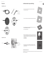 8
8
-
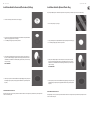 9
9
-
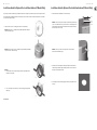 10
10
-
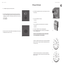 11
11
-
 12
12
-
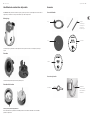 13
13
-
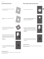 14
14
-
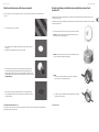 15
15
-
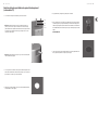 16
16
-
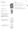 17
17
-
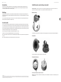 18
18
-
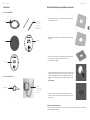 19
19
-
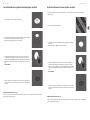 20
20
-
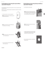 21
21
-
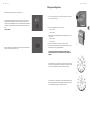 22
22
-
 23
23
-
 24
24
-
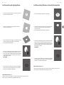 25
25
-
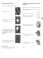 26
26
-
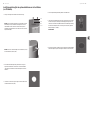 27
27
-
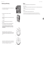 28
28
-
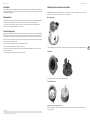 29
29
-
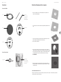 30
30
-
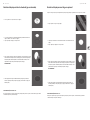 31
31
-
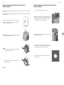 32
32
-
 33
33
-
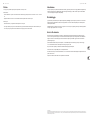 34
34
-
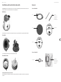 35
35
-
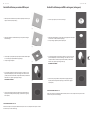 36
36
-
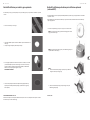 37
37
-
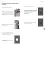 38
38
-
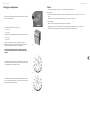 39
39
-
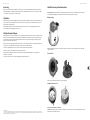 40
40
-
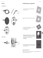 41
41
-
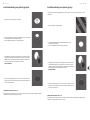 42
42
-
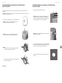 43
43
-
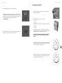 44
44
-
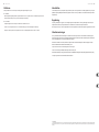 45
45
-
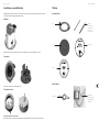 46
46
-
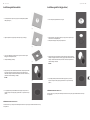 47
47
-
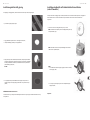 48
48
-
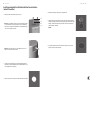 49
49
-
 50
50
-
 51
51
-
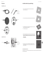 52
52
-
 53
53
-
 54
54
-
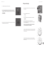 55
55
-
 56
56
-
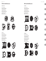 57
57
-
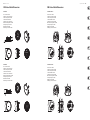 58
58
-
 59
59
-
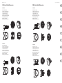 60
60
-
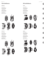 61
61
-
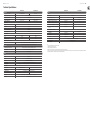 62
62
-
 63
63
-
 64
64
-
 65
65
-
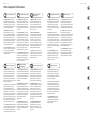 66
66
-
 67
67
-
 68
68


Tannoy CMS 403DCE Guía de inicio rápido
- Categoría
- Juguetes
- Tipo
- Guía de inicio rápido
en otros idiomas
- français: Tannoy CMS 403DCE Guide de démarrage rapide
- italiano: Tannoy CMS 403DCE Guida Rapida
- English: Tannoy CMS 403DCE Quick start guide
- Deutsch: Tannoy CMS 403DCE Schnellstartanleitung
- Nederlands: Tannoy CMS 403DCE Snelstartgids
- português: Tannoy CMS 403DCE Guia rápido
Artículos relacionados
-
Tannoy CMS 1201SW Guía de inicio rápido
-
-
Tannoy CMS 801 SUB BM Guía de inicio rápido
-
Tannoy CPA 5 Guía de inicio rápido
-
-
-
-
-
-
Otros documentos
-
Behringer VP1220F Guía de inicio rápido
-
Behringer B212XL Guía de inicio rápido
-
KlarkTeknik DN9680-MM Guía de inicio rápido
-
Bugera T5 Infinium Guía de inicio rápido
-
Turbosound TPX153 Guía de inicio rápido
-
DAS CL-6T Manual de usuario
-
 Neomounts SPEAKER-W100BLACK Manual de usuario
-
KEF CI50 Guía de instalación
-
 Squier SQ 10 Manual de usuario
-
KEF SOUNDlight Ci100QS El manual del propietario

