DeWalt D28114 Manual de usuario
- Categoría
- Herramientas eléctricas
- Tipo
- Manual de usuario

D28114
4-1/2"/5" (115 mm/125 mm) Small Angle Grinder
Mini Esmeriladora Angular de 4-1/2"/5" (115 mm/125 mm)
INSTRUCTION MANUAL
MANUAL DE INSTRUCCIONES
Questions? See us on the World Wide Web at www.DEWALT.com
¿Dudas? Visítenos en Internet: www.D
EWALT.com
INSTRUCTIVO DE OPERACIÓN, CENTROS DE SERVICIO Y PÓLIZA DE
GARANTÍA. ADVERTENCIA: LÉASE ESTE INSTRUCTIVO ANTES DE USAR
EL PRODUCTO.


1
English
Definitions: Safety Guidelines
The definitions below describe the level of severity for each
signal word. Please read the manual and pay attention to these
symbols.
DANGER: Indicates an imminently hazardous situation
which, if not avoided, will result in death or serious injury.
WARNING: Indicates a potentially hazardous situation
which, if not avoided, could result in death or serious injury.
CAUTION: Indicates a potentially hazardous situation which,
if not avoided, may result in minor or moderate injury.
CAUTION: Used without the safety alert symbol indicates a
potentially hazardous situation which, if not avoided, may result
in property damage.
WARNING: To reduce the risk of injury, read the instruction
manual.
General Power Tool Safety Warnings
WARNING! Read all safety warnings and all instructions
Failure to follow the warnings and instructions may result in
electric shock, fire and/or serious injury.
SAVE ALL WARNINGS AND INSTRUCTIONS
FOR FUTURE REFERENCE
The term “power tool”in the warnings refers to your mains-operated
(corded) power tool or battery-operated (cordless) power tool.
1) WORK AREA SAFETY
a) Keep work area clean and well lit. Cluttered or dark areas
invite accidents.
b) Do not operate power tools in explosive atmospheres,
such as in the presence of flammable liquids, gases or
dust. Power tools create sparks which may ignite the dust or
fumes.
c) Keep children and bystanders away while operating a
power tool. Distractions can cause you to lose control.
2) ELECTRICAL SAFETY
a) Power tool plugs must match the outlet. Never modify
the plug in any way. Do not use any adapter plugs with
earthed (grounded) power tools. Unmodified plugs and
matching outlets will reduce risk of electric shock.
b) Avoid body contact with earthed or grounded surfaces
such as pipes, radiators, ranges and refrigerators. There
is an increased risk of electric shock if your body is earthed or
grounded.
c) Do not expose power tools to rain or wet conditions.
Water entering a power tool will increase the risk of electric
shock.
d) Do not abuse the cord. Never use the cord for carrying,
pulling or unplugging the power tool. Keep cord away
from heat, oil, sharp edges or moving parts. Damaged or
entangled cords increase the risk of electric shock.
e) When operating a power tool outdoors, use an extension
cord suitable for outdoor use. Use of a cord suitable for
outdoor use reduces the risk of electric shock.
f) If operating a power tool in a damp location is unavoidable,
use a residual current device (RCD) protected supply.
Use of an RCD reduces the risk of electric shock.
3) PERSONAL SAFETY
a) Stay alert, watch what you are doing and use common
sense when operating a power tool. Do not use a power
tool while you are tired or under the influence of drugs,
alcohol or medication. A moment of inattention while
operating power tools may result in serious personal injury.
b) Use personal protective equipment. Always wear eye
protection. Protective equipment such as dust mask,

2
English
non-skid safety shoes, hard hat, or hearing protection used for
appropriate conditions will reduce personal injuries.
c) Prevent unintentional starting. Ensure the switch is in
the off position before connecting to power source and/
or battery pack, picking up or carrying the tool. Carrying
power tools with your finger on the switch or energising power
tools that have the switch on invites accidents.
d) Remove any adjusting key or wrench before turning the
power tool on. A wrench or a key left attached to a rotating
part of the power tool may result in personal injury.
e) Do not overreach. Keep proper footing and balance at
all times. This enables better control of the power tool in
unexpected situations.
f) Dress properly. Do not wear loose clothing or jewellery.
Keep your hair, clothing and gloves away from moving
parts. Loose clothes, jewellery or long hair can be caught in
moving parts.
g) If devices are provided for the connection of dust
extraction and collection facilities, ensure these are
connected and properly used. Use of dust collection can
reduce dust-related hazards.
4) POWER TOOL USE AND CARE
a) Do not force the power tool. Use the correct power tool
for your application. The correct power tool will do the job
better and safer at the rate for which it was designed.
b) Do not use the power tool if the switch does not turn it
on and off. Any power tool that cannot be controlled with the
switch is dangerous and must be repaired.
c) Disconnect the plug from the power source and/or the
battery pack from the power tool before making any
adjustments, changing accessories, or storing power
tools. Such preventive safety measures reduce the risk of
starting the power tool accidentally.
d) Store idle power tools out of the reach of children and do
not allow persons unfamiliar with the power tool or these
instructions to operate the power tool. Power tools are
dangerous in the hands of untrained users.
e) Maintain power tools. Check for misalignment or binding
of moving parts, breakage of parts and any other condition
that may affect the power tool’s operation. If damaged,
have the power tool repaired before use. Many accidents
are caused by poorly maintained power tools.
f) Keep cutting tools sharp and clean. Properly maintained
cutting tools with sharp cutting edges are less likely to bind
and are easier to control.
g) Use the power tool, accessories and tool bits etc., in
accordance with these instructions taking into account
the working conditions and the work to be performed.
Use of the power tool for operations different from those
intended could result in a hazardous situation.
5) SERVICE
a) Have your power tool serviced by a qualified repair
person using only identical replacement parts. This will
ensure that the safety of the power tool is maintained.
SPECIFIC SAFETY RULES
Additional Specific Safety Instructions
for Grinders
• Check that the grinding wheel backing flange has a yellow
rubber ring (D) installed, see Figure 1. Replace rubber ring if
missing, damaged or worn. See page 8 for details regarding
proper accessory installation.
WARNING: The grinding wheel or accessory may loosen
during coast-down of the tool when shut off if rubber ring is
missing or damaged. If grinding wheel or accessory loosens, it
may dismount from the machine and may cause serious personal
injury.

3
English
• Always use proper guard with grinding wheel. A guard
protects operator from broken wheel fragments and wheel contact.
• Accessories must be rated for at least the speed recom mended
on the tool warning label. Wheels and other accessories running
over rated speed can fly apart and cause injury. Accessory ratings
must be above listed minimum wheel speed as shown on tool
nameplate.
• Hold tool by insulated gripping surfaces when performing an
operation where the cutting tool may contact hidden wiring or its
own cord. Contact with a “live” wire will make exposed metal parts of
the tool “live” and shock the operator.
• Do not use Type 11 (flaring cup) wheels on this tool. Using
inappropriate accessories can result in injury.
• ALWAYS WEAR EYE PROTECTION WHEN USING THIS TOOL.
• Use of accessories not specified in this manual is not
recommended and may be hazardous. Use of power boosters
that would cause the tool to be driven at speeds greater than its rated
speed constitutes misuse.
• Do not use circular saw blades or any other toothed blades with
this tool. Serious injury may result.
• When starting the tool with a new or replacement wheel, or a
new or replacement wire brush installed, hold the tool in a well
protected area and let it run for one minute. If the wheel has an
undetected crack or flaw, it should burst in less than one minute. If the
wire brush has loose wires, they will be detected. Never start the tool
with a person in line with the wheel. This includes the operator.
• Avoid bouncing the wheel or giving it rough treatment. If this
occurs, stop the tool and inspect the wheel for cracks or flaws.
• Direct sparks away from operator, bystanders or flammable
materials. Sparks may be produced while cutting and/or grinding.
Sparks may cause burns or start fires.
• Always use side handle. Tighten the handle securely. The side
handle should always be used to maintain control of the tool at all
times.
• Never cut into area that may contain electrical wiring or
piping. Serious injury may result.
• Clean out your tool often, especially after heavy use. Dust
and grit containing metal particles often accumulate on interior
surfaces and could create an electric shock hazard.
• Do not operate this tool for long periods of time. Vibration
caused by the operating action of this tool may cause permanent
injury to fingers, hands, and arms. Use gloves to provide extra
cushion, take frequent rest periods, and limit daily time of use.
• Direct the Dust Ejection System (DES) away from operator
and coworkers. Serious injury may result (Fig. 1, K).
Causes and Operator Prevention
of Kickback
• Kickback is a sudden reaction to a pinched, bound or misaligned
wheel, wire brush or flap disc causing an uncontrolled cut-off tool
to lift up and out of the workpiece toward the operator.
• When the wheel is pinched or bound tightly by the workpiece,
the wheel stalls and the motor reaction drives the unit rapidly
back toward or away from the operator.
• Kickback is the result of tool misuse and/or incorrect operating
procedures or conditions and can be avoided by taking proper
precautions as given below:
• Maintain a firm grip with both hands on the unit and
position your body and arm to allow you to resist
kickback forces. Kickback forces can be controlled by the
operator, if proper precautions are taken.
• When wheel is binding, or when interrupting a cut for any
reason, release the trigger and hold the unit motionless
in the material until the wheel comes to a complete
stop. Never attempt to remove the unit from the work or
pull the unit backward while the wheel is in motion or
kickback may occur. Investigate and take corrective actions
to eliminate the cause of wheel binding.

4
English
• When restarting a cut-off tool in the workpiece, check
that the wheel is not engaged into the material. If wheel is
binding, it may walk up or kickback from the workpiece as the
tool is restarted.
• Support large panels to minimize the risk of wheel
pinching and kickback. Large panels tend to sag under their
own weight. Support must be placed under the panel on both
sides, near the line of cut and near the edge of the panel.
CAUTION: Use extra care when working into a corner because
a sudden, sharp movement of the grinder may be experienced
when the wheel or other accessory contacts a secondary surface
or a surface edge.
• An extension cord must have adequate wire size (AWG
or American Wire Gauge) for safety. The smaller the gauge
number of the wire, the greater the capacity of the cable, that
is 16 gauge has more capacity than 18 gauge. An undersized
cord will cause a drop in line voltage resulting in loss of power
and overheating. When using more than one extension to make
up the total length, be sure each individual extension contains
at least the minimum wire size. The following table shows the
correct size to use depending on cord length and nameplate
ampere rating. If in doubt, use the next heavier gauge. The
smaller the gauge number, the heavier the cord.
Voltage (Volts)
Total length of cord in meters (m)
120 - 127V 0 - 7 7 - 15 15 - 30 30 - 50
220 - 240V 0 - 15 15 - 30 30 - 60 60 - 100
Rated Ampere
range
Minimal cross-sectional area of the
cord in meters (mm
2
)
0 - 6A 1.0 1.5 1.5 2.5
6 - 10A 1.0 1.5 2.5 4.0
10 - 12A 1.5 1.5 2.5 4.0
12 - 16A 2.5 4.0 Not Recommended
WARNING: Always use eye protection. All users and bystanders
must wear eye protection that conforms to ANSI Z87.1.
WARNING: Always wear proper personal hearing protection
that conforms to ANSI S12.6 (S3.19) during use. Under some
conditions and duration of use, noise from this product may
contribute to hearing loss.
WARNING: ALWAYS use safety glasses. Everyday eyeglasses
are NOT safety glasses. Also use face or dust mask if cutting
operation is dusty. ALWAYS WEAR CERTIFIED SAFETY
EQUIPMENT:
• ANSI Z87.1 eye protection (CAN/CSA Z94.3),
• ANSI S12.6 (S3.19) hearing protection,
• NIOSH/OSHA/MSHA respiratory protection.
WARNING: Some dust created by power sanding, sawing,
grinding, drilling, and other construction activities contains chemicals
known to cause cancer, birth defects or other reproductive harm.
Some examples of these chemicals are:
• lead from lead-based paints,
• crystalline silica from bricks and cement and other masonry
products, and
• arsenic and chromium from chemically-treated lumber
(CCA).
Your risk from these exposures varies, depending on how often you
do this type of work. To reduce your exposure to these chemicals:
work in a well ventilated area, and work with approved safety
equipment, such as those dust masks that are specially designed
to filter out microscopic particles.
• Avoid prolonged contact with dust from power sanding,
sawing, grinding, drilling, and other construction activities.
Wear protective clothing and wash exposed areas with
soap and water. Allowing dust to get into your mouth, eyes, or
lay on the skin may promote absorption of harmful chemicals.

5
English
WARNING: Use of this tool can generate and/or disburse dust,
which may cause serious and permanent respiratory or other injury.
Always use NIOSH/OSHA approved respiratory protection
appropriate for the dust exposure. Direct particles away from face
and body.
• The label on your tool may include the following symbols. The
symbols and their definitions are as follows:
V .......... volts A ........ amperes
Hz ........ hertz W....... watts
min ....... minutes
..... alternating current
..... direct current ..... alternating or direct current
......... Class I Construction
n
o ...... no load speed
............. (grounded)
...... earthing terminal
......... Class II Construction ...... safety alert symbol
............. (double insulated) …/min per minute
RPM ..... revolutions per minute
DESCRIPTION (FIG. 1)
WARNING: Never modify the power tool or any part of it.
Damage or personal injury could result.
INTENDED USE
This tool is designed for professional grinding applications.
DO NOT use under wet conditions or in presence of flammable
liquids or gases.
This small angle grinder is a professional power tool. DO NOT let
children come into contact with the tool. Supervision is required
when inexperienced operators use this tool.
A. Paddle Switch G. Quick-Change Backing Flange
B. Lock-Off Lever H. Threaded Clamp Nut
C. Spindle Lock Button I. Type 27 Guard
D. Yellow Rubber Ring J. Lock On Button
E. Anti-Vibration Side K. Dust Ejection System™ (DES)
Handle (not shown)
F. 5" Grinding Wheel
(Type 27)
G
A
B
C
F
I
J
FIG. 1
K
K
D
H

6
English
FEATURES
E-SWITCH PROTECTION™
The ON/OFF switch has a no-volt release function. In the event of
a power outage or other unexpected shut down, the switch needs
to be cycled (turned off and on) to restart tool.
E-CLUTCH™
This unit is equipped with an E-Clutch™ (Electronic Clutch), which
in the event of a high-load or wheel pinch, the unit will shut off to
reduce the reaction torque to the user. The switch needs to be
cycled (turned off and on) to restart the tool.
POWER-OFF™ OVERLOAD PROTECTION
The power supply to the motor will be reduced in case of motor
overload. With continued motor overload, the tool will shut off. The
switch must be cycled (turned off and on) to restart tool. The power
will return to normal once the tool has cooled down to a suitable
operating temperature. NOTE: Run the tool at no load to reduce the
cool down time.
COMPLETE ELECTRONIC CONTROL™
The internal electronic speed control offers consistent wheel speed
while using the tool.
ASSEMBLY AND ADJUSTMENTS
WARNING: Turn off and unplug tool before
E
making any adjustments or removing or
installing accessories. Before reconnecting
the tool, depress and release the trigger
switch to ensure that the tool is off.
ATTACHING SIDE HANDLE
The side handle (E) can be fitted to either side
of the gear case in the threaded holes, as
shown. Before using the tool, check that the
handle is tightened se cure ly. Use a wrench to
firmly tighten the side handle.
Rotating the Gear Case
1. Remove guard and flanges from tool.
2. Remove the four corner screws attaching the gear case to
motor housing.
3. Separating the gear case from motor housing not more than
1/4", rotate the gear case head to desired position.
NOTE: If the gear case and motor housing become separated
by more than 1/4", the tool must be serviced and re-assembled
by a D
EWALT service center. Failure to have the tool serviced
may cause brush, motor and bearing failure.
4. Re-install screws to attach the gear case to the motor housing.
Tighten screws to 18 in./lbs. torque. Overtightening could cause
screws to strip.
5. Re-install guard and correct flanges for the appropriate
accessories.
Accessories
It is important to choose the correct guards, backing pads and
flanges to use with grinder accessories. See pages 9–11 for
information on choosing the correct accessories.
WARNING: Accessories must be rated for at least the speed
recom mended on the tool warning label. Wheels and other
accessories running over rated accessory speed may burst and
cause injury. Threaded accessories must have a 5/8-11 hub.
Every unthreaded accessory must have a 7/8" arbor hole. If it
does not, it may have been designed for a circular saw and should
not be used. Use only the accessories shown on pages 9–11 of
this manual. Accessory ratings must be above listed minimum
wheel speed as shown on tool nameplate.

7
English
Mounting Guard
MOUNTING AND REMOVING GUARD
WARNING: Turn off and unplug the tool before making any
adjustments or removing or installing attachments or
accessories. Before reconnecting the tool, depress and release
the paddle switch to ensure that the tool is off.
CAUTION: Guards must be used with all grinding wheels,
sanding flap discs, wire brushes, and wire wheels. The tool may be
used without a guard only when sanding with conventional sanding
discs. Some D
EWALT models are provided with a guard intended
for use with depressed center wheels (Type 27) and hubbed
grinding wheels (Type 27). The same guard is designed for use with
sanding flap discs (Type 27 and 29) and wire brushes. Grinding and
cutting with wheels other than Type 27 and 29 require different
accessory guards not included with tool. Mounting instructions for
these accessory guards are included in the accessory package.
1. Open the guard latch (M). Align the
M
O
N
lugs (N) on the guard with the slots
(O) on the gear case.
2. Push the guard down until the
guard lugs engage and rotate
freely in the groove on the gear
case hub.
Type 27 guard
4-1/2" and 5" Grinding Wheels
Quick-change
backing flange
threaded clamp nut
Type 27 hubbed wheel
Type 27 guard
Type 27 depressed
center wheel
6" Grinding Wheels
Type 27 guard
stamped steel
Quick-Change
backing flange
threaded clamp nut
Type 27 hubbed wheel
Type 27 guard
Type 27 depressed
center wheel

8
English
4-1/2" and 5" Cutting Wheels
Type 1 guard
Quick-Change
backing flange
Type 1 abrasive
cutting wheel
threaded clamp nut
Type 1 guard
Quick-Change
backing flange
diamond cutting wheel
threaded clamp nut
6" Cutting Wheels
rubber backing pad
sanding disc
threaded clamp nut
Sanding Discs
Wire Wheels
3" wire cup
brush
4" wire wheel
Type 27 guard
Type 27 guard
Type 1 guard
Quick-Change
backing flange
Type 1 abrasive
cutting wheel
threaded clamp nut
Type 1 guard
Quick-Change
backing flange
diamond cutting wheel
threaded clamp nut
Type 27 guard
Type 27 depressed
center wheel
threaded clamp nut
stamped steel
Quick-Change
backing flange

9
English
3. With the guard latch open, rotate the guard (I) into the desired
working position. The guard body should be positioned
between the spindle and the operator to provide maximum
operator protection.
4. Close the guard latch to secure the guard
I
on the gear case. You should not be able
to rotate the guard by hand when the
latch is closed. Do not operate the grinder
with a loose guard or the clamp lever in
open position.
5. To remove the guard, open the guard latch, rotate the guard so
that the arrows are aligned and pull up on the guard.
NOTE: The guard is pre-adjusted to the
P
diameter of the gear case hub at the
factory. If, after a period of time, the guard
becomes loose, tighten the adjusting screw
(P) with clamp lever in the closed position.
CAUTION: Do not tighten the adjusting
screw with the clamp lever in open position. Undetectable damage
to the guard or the mounting hub may result.
CAUTION: If guard cannot be tightened by adjusting clamp, do
not use tool and take the tool and guard to a service center to repair
or replace the guard.
OPERATION
WARNING: Always observe the safety instructions and applicable
regulations.
WARNING: To reduce the risk of serious personal injury, turn
tool off and disconnect tool from power source before making
any adjustments or removing/installing attachments
or accessories.
Guards and Flanges
It is important to choose the correct guards and flanges to use
with the grinder accessories. See pages 9–11 for the correct
accessories.
NOTE: Edge grinding and cutting can be performed with Type 27
wheels designed and specified for this purpose.
WARNING: Accessories must be rated for at least the speed
recom mended on the tool warning label. Wheels and other
accessories running over rated accessory speed may burst and
cause injury. Every unthreaded accessory must have a 7/8" arbor
hole. If it does not, it may have been designed for a circular saw and
should not be used. Use only the accessories shown on pages
9–11. Accessory ratings must be above listed minimum wheel
speed as shown on tool nameplate.
4-1/2" and 5" Sanding Flap Discs
hubbed sanding
flap disc
Quick-Change
backing flange
non-hubbed sanding
flap disc
threaded clamp nut
Type 27 guard
Type 27 guard

10
English
Switches
CAUTION: Hold the side handle and body of the tool firmly to
maintain control of the tool at start up and during use and until the
wheel or accessory stops rotating. Make sure the wheel has come
to a complete stop be fore laying the tool down.
NOTE: To reduce unexpected tool movement, do not switch the
tool on or off while under load conditions. Allow the grinder to run
up to full speed before touching the work surface. Lift the tool from
the surface before turning the tool off. Allow the tool to stop rotating
before putting it down.
SOFT START FEATURE
The soft start feature allows a slow speed build-up to avoid an initial
jerk when starting. This feature is particularly useful when working in
confined areas. Current surge will also be reduced.
PADDLE SWITCH
CAUTION: Before connecting the tool to a power source depress
and release the paddle switch (A) once without depressing the lock-
on button (Fig. 1, J) to ensure that the switch is off. Depress and
release the paddle switch as described above after any interruption
in power supply to the tool, such as the activation of a ground fault
interrupter, throwing of a circuit breaker, accidental unplugging, or
power failure.
To turn the tool on, push the
A
B
lock-off lever (B) toward the back of
the tool, then depress the paddle
switch (A). The tool will run while the
switch is depressed. Turn the tool off
by releasing the paddle switch.
WARNING: Do not disable the lock-off lever. If the lock-off lever
is disabled, the tool may start unexpectedly when it is laid down.
LOCK-ON BUTTON
The lock-on button (J) offers increased
J
A
B
comfort in extended use applications.
To lock the tool on, push the lock-off
lever (B) toward the back of the tool
then depress the paddle switch (A).
With the tool running, depress the lock-
on button (J). The tool will continue to
run after the paddle switch is released. To unlock the tool, depress
and release the paddle switch. This will cause the tool to stop.
CAUTION: Allow the tool to reach full speed before touching tool
to the work surface. Lift the tool from the work surface before
turning the tool off.
SPINDLE LOCK
C
The spindle lock (C) is provided to prevent
the spindle from rotating when installing or
removing wheels. Operate the spindle lock
only when the tool is turned off, unplugged
from the power supply, and has come to
a complete stop. Do not engage the spindle lock while the tool is
operating because damage to the tool will result. To engage the
lock, depress the spindle lock button and rotate the spindle until you
are unable to rotate the spindle further.
Mounting and Using Depressed Center
Grinding Wheels and Sanding Flap Discs
MOUNTING AND REMOVING HUBBED WHEELS
WARNING: Turn off and unplug the tool before making any
adjustments or removing or installing attachments or
accessories. Before reconnecting the tool, depress and release
the paddle switch to ensure that the tool is off.

11
English
Hubbed wheels install directly on the 5/8-11 threaded spindle.
Thread of accessory must match thread of spindle.
1. Backing flange is retained to the grinder by an O-ring on the
spindle. Remove backing flange by pulling and twisting flange
away form the machine.
2. Thread the wheel on the spindle by hand.
3. Depress the spindle lock button and use a wrench to tighten the
hub of the wheel.
4. Reverse the above procedure to remove the wheel.
CAUTION: Failure to properly seat the wheel before turning the
tool on may result in damage to the tool or the wheel.
MOUNTING NON-HUBBED WHEELS
G
D
WARNING: Turn off and unplug the
tool before making any adjustments or
removing or installing attachments or
accessories. Before reconnecting the
tool, turn the switch on and off as
previously described to ensure that the
tool is off.
Depressed center Type 27 grinding wheels
H
must be used with included flanges.
1. Be sure the backing flange recess is
seated onto the flats of the spindle by
pushing and twisting the flange before
placing wheel.
2. Place wheel against the backing flange, centering the wheel on
the raised section (pilot) of the backing flange.
3. While depressing the spindle lock button, thread the clamp nut
(H) on spindle. If the wheel you are installing is more than 1/8"
(3.31mm) thick, place the threaded clamp nut on the spindle so
that the raised section (pilot) fits into the center of the wheel.
If the wheel you are installing is 1/8" (3.31mm) thick or less,
place the threaded clamp nut on the spindle so that the raised
section (pilot) is not against the wheel.
4. While depressing the spindle lock button,
1/4" WHEELS
(6.35 mm)
Quick-Change
backing flange
threaded clamp nut
1/8" WHEELS
(3.17 mm)
threaded clamp nut
Quick-Change
backing flange
tighten the clamp nut with a wrench.
5. To remove the wheel, depress the
spindle lock button and loosen the
threaded clamp nut with a wrench.
NOTE: If the wheel spins after the clamp
nut is tightened, check the orientation of
the threaded clamp nut. If a thin wheel is
installed with the pilot on the clamp nut
against the wheel, it will spin because the
height of the pilot prevents the clamp nut
from holding the wheel.
SURFACE GRINDING WITH GRINDING
WHEELS
1. Allow the tool to reach full speed before
touching the tool to the work surface.
2. Apply minimum pressure to the work
surface, allowing the tool to operate at
high speed. Grinding rate is greatest
when the tool operates at high speed.
3. Maintain a 20˚ to 30˚ angle between the
20˚-30˚
tool and work surface.
4. Continuously move the tool in a forward
and back motion to avoid creating gouges
in the work surface.
5. Remove the tool from work surface before turning tool off. Allow
the tool to stop rotating before laying it down.
EDGE GRINDING WITH GRINDING WHEELS
CAUTION: Wheels used for cutting and edge grinding may break
if they bend or twist while the tool is being used to do cut-off work or
deep grinding. To reduce the risk of serious injury, limit the use of
these wheels with a standard Type 27 guard to shallow cutting and
notching (less than 1/2" in depth). The open side of the guard must

12
English
be positioned away from the operator. For deeper cutting with a
Type 1 cut-off wheel, use a closed, Type 1 guard. See the chart on
page 14 for more information. Type 1 guards are available at extra
cost from your local dealer or authorized service center.
1. Allow the tool to reach full speed before
touching the tool to the work surface.
2. Apply minimum pressure to the work
surface, allowing the tool to operate at
high speed. Grinding rate is greatest
when the tool operates at high speed.
3. Position yourself so that the open-
underside of the wheel is facing away
from you.
4. Once a cut is begun and a notch is
established in the workpiece, do not
change the angle of the cut. Changing
the angle will cause the wheel to bend and may cause wheel
breakage. Edge grinding wheels are not designed to withstand
side pressures caused by bending.
5. Remove the tool from the work surface before turning the tool
off. Allow the tool to stop rotating before laying it down.
WARNING: Do not use edge grinding/cutting wheels for surface
grinding applications because these wheels are not designed for
side pressures encountered with surface grinding. Wheel breakage
and injury may result.
SURFACE FINISHING WITH SANDING FLAP DISCS
1. Allow the tool to reach full speed before touching the tool to the
work surface.
2. Apply minimum pressure to work
5˚-10˚
surface, allowing the tool to operate
at high speed. Sanding rate is
greatest when the tool operates at
high speed.
3. Maintain a 5˚ to 10˚ angle between the tool and work surface.
4. Continuously move the tool in a forward and backward motion to
avoid creating gouges in the work surface.
5. Remove the tool from work surface before turning tool off. Allow
the tool to stop rotating before laying it down.
MOUNTING SANDING BACKING PADS
WARNING: Turn off and unplug the tool before making any
adjustments or removing or installing attachments or
accessories. Before reconnecting the tool, turn the switch on
and off as previously described to ensure that the tool is off.
CAUTION: Proper guard must be reinstalled for grinding wheel,
sanding flap disc, wire brush or wire wheel applications after
sanding applications are complete.
1. Place or appropriately thread
H
R
S
pad backing (R) on the spindle.
2. Place the sanding disc (S) on the
backing pad.
3. While depressing spindle lock,
thread clamp nut (H) on spindle,
piloting the raised hub on the clamp
nut into the center of san ding disc
and backing pad.
4. Tighten the clamp nut by hand.
Then depress the spindle lock
button while turning the sanding disc until the sanding disc and
clamp nut are snug.
5. To remove the wheel, grasp and turn the backing pad and
sanding pad while depressing the spindle lock button.
USING SANDING BACKING PADS
Choose the proper grit sandpaper for your application. Sandpaper is
available in various grits. Coarse grits yield faster material removal
rates and a rougher finish. Finer grits yield slower material removal
and a smoother finish.

13
English
Begin with coarse grit discs for fast, rough material removal. Move to a
medium grit paper and finish with a fine grit disc for optimal finish.
Coarse 16 - 30 grit
Medium 36 - 80 grit
Fine Finishing 100 - 120 grit
Very Fine Finishing 150 - 180 grit
1. Allow the tool to reach full speed before touching tool to the
work surface.
2. Apply minimum pressure to work surface, allowing the tool to
operate at high speed. Sanding rate is greatest when the tool
operates at high speed.
3. Maintain a 5˚ to 15˚ angle between
5˚-15˚
the tool and work surface. The san ding
disc should contact approximately one
inch of work surface.
4. Move the tool constantly in a straight
line to prevent burning and swirling
of work surface. Allowing the tool to rest on the work surface
without moving, or moving the tool in a circular motion causes
burning and swirling marks on the work surface.
5. Remove the tool from work surface before turning tool off. Allow
the tool to stop rotating before laying it down.
Mounting and Using Wire Brushes
and Wire Wheels
Wire cup brushes or wire wheels screw directly on the grinder
spindle without the use of flanges. Use only wire brushes or
wheels provided with a 5/8-11 threaded hub. A Type 27 guard is
required when using wire brushes and wheels.
CAUTION: Wear work gloves when handling wire brushes
and wheels. They can become sharp.
CAUTION: Wheel or brush must not touch guard when mounted
or while in use. Undetectable damage could occur to the accessory,
causing wires to fragment from accessory wheel or cup.
MOUNTING WIRE BRUSHES AND WIRE WHEELS
WARNING: Turn off and unplug the tool before making any
adjustments or removing or installing attachments or
accessories. Before reconnecting the tool, turn the switch on
and off as previously described to ensure that the tool is off.
1. Thread the wheel on the spindle by hand.
2. Depress spindle lock button and use a wrench on the hub of the
wire wheel or brush to tighten the wheel.
3. To remove the wheel, reverse the above procedure.
CAUTION: Failure to properly seat the wheel hub before turning
the tool on may result in damage to tool or wheel.
USING WIRE CUP BRUSHES AND WIRE WHEELS
Wire wheels and brushes can be used for removing rust, scale and
paint, and for smoothing irregular surfaces.
1. Allow the tool to reach full speed before touching the tool to the
work surface.
2. Apply minimum pressure to work surface, allowing the tool to
operate at high speed. Material removal rate is greatest when
the tool operates at high speed.
3. Maintain a 5˚ to 10˚ angle between the
5˚-10˚
tool and work surface for wire cup
brushes.
4. Maintain contact between the edge of
the wheel and the work surface with
wire wheels.
5. Continuously move the tool in a forward and backward motion
to avoid creating gouges in the work surface. Allowing the tool
to rest on the work surface without moving, or moving the tool
in a circular motion causes burning and swirling marks on the
work surface.

14
English
6. Remove the tool from the work surface
before turning the tool off. Allow the tool to
stop rotating before setting it down.
CAUTION: Use extra care when working over
an edge, as a sudden sharp movement of
grinder may be experienced.
Mounting and Using Cutting
(Type 1) Wheels
Cutting wheels include diamond wheels and abrasive discs.
Abrasive cutting wheels for metal and concrete use are available.
Diamond blades for concrete cutting can also be used.
NOTE: All grinders that use Type 1 wheels use the quick-change
backing flange (G).
WARNING: Fail ure to use proper flange and guard can re sult in
injury resulting from wheel breakage and wheel contact. See page 8
for more information.
MOUNTING CLOSED (TYPE 1) GUARD
WARNING: Turn off and unplug the tool before making any
adjustments or removing or installing attachments or
accessories. Before reconnecting the tool, turn the switch on
and off as previously described to ensure that the tool is off.
1. Open the guard latch (M). Align
M
O
N
the lugs (N) on the guard with the
slots (O) on the gear case.
2. Push the guard down until the
guard lug engages and rotates
freely in the groove on the gear
case hub.
3. Rotate guard (I) into desired working
I
position. The guard body should be
positioned between the spindle and
the operator to provide maximum
operator protection.
4. Close the guard latch to secure the
guard on the gear case cover. You
should be unable to rotate the guard by
P
hand when the latch is in closed position.
If rotation is possible, tighten the
adjusting screw (P) with clamp lever in
the closed position. Do not operate
grinder with a loose guard or clamp
lever in open position.
5. To remove the guard, open the guard
latch, rotate the guard so that the arrows are aligned and pull
up on the guard.
NOTE: If, after a period of time, the guard becomes loose, tighten
the adjusting screw (P) with the clamp lever in the closed position.
CAUTION: Do not tighten adjusting screw with clamp lever in
open position. Undetectable damage to guard or mounting hub
may result.
MOUNTING CUTTING WHEELS
WARNING: Turn off and unplug the tool before making any
adjustments or removing or installing attachments or
accessories. Before reconnecting the tool, turn the switch on
and off as previously described to ensure that the tool is off.
CAUTION: Matching diameter backing flange and threaded
clamp nut (included with tool) must be used for cutting wheels.
1. Place the quick-change backing flange on spindle with the
raised section (pilot) facing up. The raised section (pilot) on
the backing flange will be against the wheel when the wheel is
installed.

15
English
2. Place the wheel on the backing flange, centering the wheel on
the raised section (pilot).
3. Install the threaded clamp nut with the raised section (pilot)
facing away from the wheel.
4. Depress the spindle lock button and tighten clamp nut with
a wrench.
5. To remove the wheel, grasp and turn while depressing the
spindle lock button.
USING CUTTING WHEELS
WARNING: Do not use edge grinding/ cutting
wheels for surface grinding applications
because these wheels are not designed for side
pressures encountered with surface grinding.
Wheel breakage and injury may result.
1. Allow tool to reach full speed before
touching tool to work surface.
2. Apply minimum pressure to work surface,
allowing tool to operate at high speed.
Cutting rate is greatest when the tool
operates at high speed.
3. Once a cut is begun and a notch is established in the workpiece,
do not change the angle of the cut. Changing the angle will
cause the wheel to bend and may cause wheel breakage.
4. Remove the tool from work surface before turning tool off. Allow
the tool to stop rotating before setting it down.
MAINTENANCE
Your DEWALT power tool has been designed to operate over a
long period of time with a minimum of maintenance. Continuous
satisfactory operation depends upon proper tool care and regular
cleaning.
WARNING: To reduce the risk of injury, turn unit off and
disconnect tool from power source before installing and
removing accessories, before making any adjustments or
removing/installing attachments or accessories.
Lubrication
Your power tool requires no additional lubrication.
Cleaning
WARNING: Blow dirt and dust out of the main housing with dry
air as often as dirt is seen collecting in and around the air vents.
Wear approved eye protection and approved dust mask when
performing this procedure.
WARNING: Never use solvents or other harsh chemicals for
cleaning the non-metallic parts of the tool. These chemicals may
weaken the materials used in these parts. Use a cloth dampened
only with water and mild soap. Never let any liquid get inside the
tool; never immerse any part of the tool into a liquid.
Accessories
WARNING: Since accessories, other than those offered by
D
EWALT, have not been tested with this product, use of such
accessories with this tool could be hazardous. To reduce the risk of
injury, only D
EWALT, recommended accessories should be used
with this product.
Recommended accessories for use with your tool are available at
extra cost from your local dealer or authorized service center

16
Español
16
Definiciones: Normas
de seguridad
Las siguientes definiciones describen el nivel de gravedad de
cada advertencia. Lea el manual y preste atención a estos
símbolos.
PELIGRO:
indica una situación de peligro inminente que, si
no se evita,
provocará
la
muerte o lesiones graves.
ADVERTENCIA:
Indica una situación de peligro potencial
que, si no se evita,
podría
provocar la
muerte o lesiones
graves
ATENCIÓN:
Indica una situación de peligro potencial que, si
no se evita,
puede
provocar
lesiones leves o moderadas.
ATENCIÓN:
Utilizado sin el símbolo de alerta de seguridad
indica una situación de peligro potencial que, si no se evita,
puede provocar
daños en la
propiedad
.
ADVERTENCIA: para reducir el riesgo de lesiones, lea el
manual de instrucciones.
Advertencias generales de seguridad
para las herramientas eléctricas
ADVERTENCIA: Lea todas las advertencias de seguridad
e instrucciones. El incumplimiento de las advertencias o
instrucciones puede provocar descargas eléctricas, incendios o
lesiones graves.
GUARDE LAS ADVERTENCIAS E
INSTRUCCIONES PARA PODER
CONSULTARLAS EN EL FUTURO
El término “herramienta eléctrica” incluido en todas las advertencias
se refiere a su herramienta eléctrica conectada a la red (cable
eléctrico) o a su herramienta eléctrica accionada con baterías
(inalámbrica).
1) SEGURIDAD DEL ÁREA DE TRABAJO
a) Mantenga el área de trabajo limpia y bien iluminada. Las
áreas abarrotadas u oscuras propician accidentes.
b) No haga funcionar las herramientas eléctricas en
atmósferas explosivas, como ambientes donde haya
polvo, gases o líquidos inflamables. Las herramientas
eléctricas originan chispas que pueden encender el polvo o
producir humo.
c) Mantenga alejados a los niños y a los espectadores
de la herramienta eléctrica en funcionamiento. Las
distracciones pueden provocar la pérdida de control.
2) SEGURIDAD ELÉCTRICA
a) Los enchufes de la herramienta eléctrica deben adaptarse
a la toma de corriente. Nunca modifique el enchufe de
ninguna manera. No utilice ningún enchufe adaptador
con herramientas eléctricas con conexión a tierra. Los
enchufes no modificados y que se adaptan a las tomas de
corrientes reducirán el riesgo de descarga eléctrica.
b) Evite el contacto corporal con superficies con toma de
tierra como, por ejemplo, tuberías, radiadores, cocinas y
refrigeradores. Existe mayor riesgo de descarga eléctrica si
su cuerpo está puesto a tierra.
c) No exponga las herramientas eléctricas a la lluvia ni a
condiciones de humedad. Si entra agua en una herramienta
eléctrica, aumentará el riesgo de descarga eléctrica.
d) No use el cable indebidamente. Nunca utilice el cable para
transportar, tirar o desenchufar la herramienta eléctrica.
Mantenga el cable alejado del calor, el aceite, los bordes
afilados o las piezas móviles. Los cables dañados o
enredados aumentan el riesgo de descarga eléctrica.
e) Al operar una herramienta eléctrica en el exterior, utilice
un cable prolongador adecuado para tal uso. Utilice un
cable adecuado para uso en exteriores a fin de reducir el
riesgo de descarga eléctrica.

17
Español
17
f) Si no se puede evitar el uso de una herramienta eléctrica
en una zona húmeda, utilice un dispositivo de corriente
residual (residual current device, RCD) de seguridad.
El uso de un RCD reduce el riesgo de sufrir una descarga
eléctrica.
3) SEGURIDAD PERSONAL
a) Permanezca alerta, controle lo que está haciendo y utilice el
sentido común cuando emplee una herramienta eléctrica.
No utilice una herramienta eléctrica si está cansado o
bajo el efecto de drogas, alcohol o medicamentos. Un
momento de descuido mientras se opera una herramienta
eléctrica puede provocar lesiones personales graves.
b) Utilice equipo de seguridad personal. Utilice siempre
protección ocular. El uso de equipo de seguridad, como
mascarillas para polvo, calzado de seguridad antideslizante,
cascos o protección auditiva en las condiciones adecuadas
reducirá las lesiones personales.
c) Evite poner en marcha la herramienta involuntariamente.
Asegúrese de que el interruptor está apagado antes de
conectar la fuente de alimentación y/o la batería, coger
o transportar la herramienta. Transportar herramientas
eléctricas con su dedo apoyado sobre el interruptor o
enchufar herramientas eléctricas con el interruptor en la
posición de encendido puede propiciar accidentes.
d) Retire la clavija de ajuste o la llave de tuercas antes de
encender la herramienta eléctrica. Una llave de tuercas
o una clavija de ajuste que quede conectada a una pieza
giratoria de la herramienta eléctrica puede provocar lesiones
personales.
e) No se estire demasiado. Conserve el equilibrio y
posiciónese adecuadamente en todo momento. Esto
permite un mejor control de la herramienta eléctrica en
situaciones inesperadas.
f) Use la vestimenta adecuada. No use ropas holgadas ni
joyas. Mantenga el cabello, la ropa y los guantes alejados
de las piezas en movimiento. Las ropas holgadas, las joyas
o el cabello largo pueden quedar atrapados en las piezas
en movimiento.
g) Si se suministran dispositivos para la conexión de
accesorios con fines de recolección y extracción de
polvo, asegúrese de que estén conectados y que se
utilicen correctamente. El uso del extractor de polvo puede
reducir los riesgos relacionados con el polvo.
4) USO Y MANTENIMIENTO DE LA HERRAMIENTA
ELÉCTRICA
a) No fuerce la herramienta eléctrica. Utilice la herramienta
eléctrica correcta para el trabajo que realizará. La
herramienta eléctrica correcta hará el trabajo mejor, y de un
modo más seguro, a la velocidad para la que fue diseñada.
b) No utilice la herramienta eléctrica si no puede encenderla
o apagarla con el interruptor. Las herramientas que no
puedan ser controladas con el interruptor constituyen un
peligro y deben repararse.
c) Desconecte el enchufe de la fuente de alimentación o
la batería de la herramienta eléctrica antes de realizar
cualquier ajuste, cambio de accesorios o almacenar
las herramientas eléctricas. Estas medidas de seguridad
preventivas reducen el riesgo de encender la herramienta
eléctrica de forma accidental.
d) Guarde la herramienta eléctrica que no esté en uso fuera
del alcance de los niños y no permita que otras personas
no familiarizadas con ella o con estas instrucciones
operen la herramienta. Las herramientas eléctricas son
peligrosas si son operadas por usuarios que no tienen
formación.

18
Español
18
e) Mantenimiento de las herramientas eléctricas. Revise que
no haya piezas en movimiento mal alineadas o trabadas,
piezas rotas o cualquier otra situación que pueda afectar
el funcionamiento de las herramientas eléctricas. Si
encuentra daños, haga reparar la herramienta eléctrica
antes de utilizarla. Se producen muchos accidentes a
causa de las herramientas eléctricas que carecen de un
mantenimiento adecuado.
f) Mantenga las herramientas de corte afiladas y limpias.
Las herramientas de corte con mantenimiento adecuado y
con los bordes de corte afilados son menos propensas a
trabarse y son más fáciles de controlar.
g) Utilice las herramientas eléctricas, sus accesorios y
piezas, etc. de acuerdo con las presentes instrucciones,
teniendo siempre en cuenta las condiciones de trabajo y
el trabajo que deba llevar a cabo. El uso de la herramienta
eléctrica para operaciones diferentes de aquellas para las
que fue diseñada podría originar una situación peligrosa.
5) MANTENIMIENTO
a) Solicite a una persona cualificada en reparaciones que
realice el mantenimiento de su herramienta eléctrica
y que solo utilice piezas de repuesto idénticas. Esto
garantizará la seguridad de la herramienta eléctrica.
NORMAS ESPECÍFICAS DE SEGURIDAD
Instrucciones de seguridad adicionales
específicas para esmeriladoras
• Verifique que el flange de respaldo del disco para esmerilar
tenga un anillo de goma (D) amarillo instalado (Fig. 1).
Reemplace el anillo de goma en caso de que falte, esté
dañado o presente desgaste. Consulte la página 25 para
obtener información detallada en relación con la instalación
correcta de accesorios.
ADVERTENCIA: El disco para esmerilar o los accesorios
pueden aflojarse cuando la herramienta gire para apagarse si
el anillo de goma falta o está dañado. Si el disco para esmerilar
o los accesorios se aflojan, pueden salirse de la máquina y
ocasionar lesiones personales graves.
• Utilice siempre el protector apropiado con el disco de
esmerilar. Protegerá al operador de los fragmentos si se rompe
un disco, y del contacto con el disco.
• Los accesorios deben estar clasificados para la velocidad
recomendada en la etiqueta de advertencia de la
herramienta, como mínimo. Los discos y otros accesorios que
funcionen por encima de la velocidad nominal pueden quebrarse,
despedir fragmentos y provocar lesiones. La velocidad nominal
de los accesorios debe ser superior a la velocidad mínima
aprobada del disco, indicada en la placa de la herramienta.
• Sostenga la herramienta por las superficies de agarre
aisladas cuando realiza una operación donde la herra-
mienta de corte puede tocar cables eléctricos escondidos
o su propio cable. El contacto con un cable con “corriente
eléctrica” hará que las partes metálicas expuestas de la
herramienta tengan “corriente eléctrica” y el operador sufra
una descarga eléctrica.
• No utilice discos Tipo 11 (copas cónicas) en esta herra-
mienta. El uso de accesorios incorrectos puede producir
lesiones.
• UTILICE SIEMPRE PROTECCIÓN PARA LOS OJOS
CUANDO USE ESTA HERRAMIENTA.
• No se recomienda el uso de accesorios no especificados en
este manual, que constituyen un riesgo. El uso de elevadores
de tensión que pueden provocar que la herramienta opere a
velocidades mayores que su velocidad nominal constituye mal
uso.

19
Español
19
• No utilice hojas de sierra circular o cualquier otro tipo de
hojas dentadas en esta herramienta. Puede causar lesiones
graves.
• Al encender la herramienta con un disco o un cepillo nuevo
o de repuesto instalado, sostenga la herramienta en un
área protegida y hágala funcionar durante un minuto. Si el
disco o el cepillo tiene una grieta o un defecto que pasó
desapercibido, se desintegrará o separará en menos de un
minuto. Se detectará si el cepillo de alambre tiene alambres
sueltos. Nunca encienda la herramienta si una persona está
parada frente al disco. Esta instrucción incluye al operador.
• Evite darle botes al disco o maltratarlo. Si esto sucede,
detenga la herramienta e inspeccione el disco para detectar
grietas o defectos.
• Dirija las chispas lejos del operador, los espectadores
o los materiales inflamables. Se pueden producir chispas
mientras se corta o se esmerila. Las chispas pueden provocar
quemaduras o iniciar incendios.
• Siempre utilice la agarradera lateral. Ajuste la agarradera
con firmeza. Se debe utilizar siempre la agarradera lateral para
mantener el control de la herramienta en todo momento.
• Nunca corte en un área que pueda contener cables
eléctricos o cañerías. Puede causar lesiones graves.
• Limpie su herramienta con frecuencia, especialmente
después de un uso intensivo. A menudo se acumulan sobre
las superficies interiores polvo y suciedad que contienen
partículas metálicas, que pueden provocar riesgo de descarga
eléctrica.
• No haga funcionar esta herramienta durante períodos
prolongados. La vibración que produce el funcionamiento de
esta herramienta puede provocar lesiones permanentes en
dedos, manos y brazos. Use guantes para proveer amortiguación
extra, tome descansos frecuentes y limite el tiempo diario de
uso.
• Dirija el sistema de evacuación de polvo (DES, por su sigla
en inglés) de manera que no apunte hacia el operador o
sus compañeros de trabajo. Puede causar lesiones graves
(Fig. 1, K).
Causas del retroceso y su prevención
por parte del operador
• El retroceso es una reacción repentina al pellizco, el atascamiento
o la desalineación de un disco, un cepillo de alambre o un disco
de lija, que causa que la herramienta de corte salte del trabajo
en dirección al operador.
• Cuando el trabajo pellizca o atasca el disco, el disco se detiene
y la reacción del motor impulsa a la unidad hacia atrás con
rapidez, hacia el operador o en la dirección opuesta.
• El retroceso es el resultado de un mal uso de la herramienta
o de condiciones o procedimientos operativos incorrectos y
se puede evitar tomando las precauciones apropiadas que se
indican a continuación:
• Sujete la herramienta firmemente con ambas manos y
ubique su cuerpo y el brazo para poder resistir las fuerzas
de retroceso. El operador puede controlar las fuerzas de
retroceso, si se toman las precauciones correctas.
• Cuando se está atascando el disco, o cuando se
interrumpe un corte por alguna razón, suelte el disparador
y mantenga la unidad quieta en el material hasta que el
disco se detenga completamente. Nunca intente retirar
la unidad del trabajo o tirar de la unidad hacia atrás
mientras la rueda esté en movimiento, o se producirá un
retroceso. Investigue y tome las medidas correctivas para
eliminar la causa del atascamiento del disco.
• Cuando se vuelve a arrancar una herramienta de corte
en el trabajo, verifique que el disco no esté trabado en
el material. Si el disco está atascado, cuando se vuelve a
arrancar la herramienta, la misma puede saltarse del trabajo
o producir un retroceso.

20
Español
20
• Sujete los paneles grandes para minimizar el riesgo de
que el disco se pellizque y se produzca el retroceso. Los
paneles grandes tienden a combarse por su propio peso. Se
deben colocar soportes bajo el panel, a ambos lados, cerca
de la línea de corte y cerca del borde del panel.
ATENCIÓN: Tenga mucho cuidado al trabajar en una esquina
ya que puede producirse un movimiento repentino y violento de la
esmeriladora si el disco u otro accesorio entra en contacto con una
segunda superficie o el borde de la misma.
• Los hilos del alargador deben ser de un calibre apropiado
(AWG o American Wire Gauge) para su seguridad. Mientras
menor sea el calibre del hilo, mayor la capacidad del cable. Es
decir, un hilo calibre 16 tiene mayor capacidad que uno de 18.
Un cable de un calibre insuficiente causará una caída en la
tensión de la línea dando por resultado una pérdida de energía
y sobrecalentamiento. Cuando se utilice más de un alargador
para completar el largo total, asegúrese que los hilos de cada
alargador tengan el calibre mínimo. La tabla siguiente muestra
el tamaño correcto a utilizar, dependiendo de la longitud del
cable y del amperaje nominal de la placa de identificación.
Si tiene dudas sobre cuál calibre usar, use un calibre mayor.
Cuanto más pequeño sea el número del calibre, más resistente
será el cable.
Ténsion (Volts) Longitud del cable en metros (m)
120 - 127V 0 - 7 7 - 15 15 - 30 30 - 50
220 - 240V 0 - 15 15 - 30 30 - 60 60 - 100
Corriente
nominal
(Ampéres)
Sección nominal mínima del cable en
milímetros cuadrados (mm
2
)
0 - 6A 1,0 1,5 1,5 2,5
6 - 10A 1,0 1,5 2,5 4,0
10 - 12A 1,5 1,5 2,5 4,0
12 - 16A 2,5 4,0 No recomendado
ADVERTENCIA: Siempre use protección ocular. Todos los
usuarios y las personas circunstantes deben llevar protección
ocular en conformidad con ANSI Z87.1.
ADVERTENCIA: Siempre lleve la debida protección auditiva
personal en conformidad con ANSI S12.6 (S3.19) durante el
uso de esta herramienta. Bajo algunas condiciones y duraciones
de uso, el ruido producido por este producto puede contribuir a la
pérdida auditiva.
ADVERTENCIA: Use SIEMPRE lentes de seguridad. Los
anteojos de diario NO SON lentes de seguridad. Utilice además
una máscara para la cara o guardapolvo si la operación de
corte genera demasiado polvo. SIEMPRE LLEVE EQUIPO DE
SEGURIDAD CERTIFICADO:
• Protección ocular ANSI Z87.1 (CAN/CSA Z94.3),
• Protección auditiva ANSI S12.6 (S3.19),
• Protección respiratoria NIOSH/OSHA/MSHA.
ADVERTENCIA: Parte del polvo generado al lijar, serrar,
esmerilar o taladrar, así como al realizar otras actividades del
sector de la construcción, contienen productos químicos que
pueden producir cáncer, defectos congénitos u otras afecciones
reproductivas. Algunos ejemplos de estos químicos son:
• plomo de algunas pinturas,
• polvo de sílice proveniente de ladrillos y cemento y otros
productos de albañilería, y
• arsénico y cromo provenientes de maderas tratadas con
químicos (arseniato de cobre cromado).
Su riesgo de exposición a estos químicos varía, dependiendo de
la frecuencia con la cual realiza usted este tipo de trabajo. Para
reducir la exposición a esas sustancias químicas: trabaje en una
zona bien ventilada y llevando equipos de seguridad aprobados,
como mascarillas antipolvo especialmente diseñadas para filtrar
partículas microscópicas.

21
Español
21
• Evite el contacto prolongado con polvo generado por
el lijado, serrado, pulido y taladrado eléctrico y otras
actividades de construcción. Vista ropa protectora y lave
las áreas de la piel expuestas con agua y jabón. Si permite
que el polvo se introduzca en la boca u ojos o quede sobre
la piel, puede favorecer la absorción de productos químicos
peligrosos.
ADVERTENCIA: La utilización de esta herramienta puede
generar polvo o dispersarlo, lo que podría causar daños graves
y permanentes al sistema respiratorio, así como otras lesiones.
Siempre use protección respiratoria aprobada por NIOSH
(Instituto Nacional de Seguridad y Salud en el Trabajo) u OSHA
(Administración de Seguridad y Salud en el Trabajo) apropiada
para la exposición al polvo. Dirija las partículas en dirección
contraria a la cara y el cuerpo.
• La etiqueta de su herramienta puede incluir los siguientes
símbolos. Estos símbolos y sus definiciones son:
V ........ voltios A ........... amperios
Hz ...... hercios W .......... vatios
min ....minutos
........ corriente alterna
... corriente directa ........ corriente alterna
......Construcción Clase I ............. o corriente directa
..........(conectada a tierra)
n
o ......... velocidad sin carga
.......terminal de conexión ......... Construcción Clase II
....... a tierra ............. (doble aislamiento)
......símbolo de advertencia …/min ... por minuto
..........de seguridad RPM ..... revoluciones por
.......... ............. minuto
DESCRIPCIÓN (FIG. 1, 3)
ADVERTENCIA: Nunca modifique la herramienta eléctrica,
ni tampoco ninguna de sus piezas. Podría producir lesiones
corporales o daños.
USO PREVISTO
Esta herramienta es diseñados para aplicaciones profesionales de
perforación y atornillado.
NO USE la herramienta bajo condiciones de humedad o en
presencia de gases o líquidos inflamables.
La esmeriladora de ángulo pequeño esta herramienta profesional.
NO permita que los niños entren en contacto con la herramienta.
Cuando la hagan funcionar operarios sin experiencia, es necesaria
supervisión.
COMPONENTES (Fig. 1)
A. Interruptor de paleta
B. Palanca de bloqueo
C. Botón de bloqueo del eje
D. Anillo de goma amarillo
E. Mango lateral con sistema antivibración (no se muestra)
F. Disco de esmerilar de 127 mm (5") (Tipo 27)
G. Flange de respaldo de cambio rápido
H. Tuerca de fijación roscada
I. Protector Tipo 27
J. Botón de bloqueo
K. Dust Ejection System™ (DES)

22
Español
22
G
A
B
C
F
I
J
FIG. 1
K
K
D
H
CARACTERÍSTICAS
E-SWITCH PROTECTION™
El interruptor de encendido y apagado tiene una función de no
liberación de voltios. En el caso de un corte eléctrico u otro suceso
que produzca un apagón inesperado, el interruptor tiene que pasar
un ciclo (apagarse y encenderse) para reiniciar la herramienta.
E-CLUTCH™
Esta unidad está equipada con un embrague E-Clutch™
(embrague electrónico), que, en el caso de tener mucha carga
o de que se pellizque el disco, apagará la unidad para reducir la
torsión de reacción al usuario.El interruptor debe pasar un ciclo
(apagarse y encenderse) para reiniciar la herramienta.
PROTECCIÓN CONTRA SOBRECARGA POWER-OFF™
El suministro de energía al motor se reducirá en caso de sobrecarga
al motor. Si hay una sobrecarga continua, la herramienta se
apagará. El interruptor debe pasar un ciclo (apagarse y encenderse)
para reiniciar la herramienta. La energía volverá al nivel normal
una vez que la herramienta se haya enfriado y tenga una
temperatura de funcionamiento adecuada.
NOTA: Haga funcionar la herramienta sin carga para reducir el
tiempo de inactividad porque la unidad está fría.
COMPLETE ELECTRONIC CONTROL™
El control electrónico de velocidad interno permite que el disco
tenga una velocidad uniforme mientras se usa la herramienta.
ENSAMBLADO Y AJUSTES
ADVERTENCIA: Apague y desenchufe la herramienta antes
de realizar ajustes o de retirar o instalar cualquier accesorio.
Antes de volver a conectar la herramienta, oprima y libere el
interruptor disparador para asegurarse de que la herramienta
esté apagada.
CONEXIÓN DEL MANGO LATERAL
E
El mango lateral (E) se puede colocar en
cualquiera de los lados de la caja de engranajes,
en los agujeros roscados, según se muestra.
Antes de utilizar la herramienta, verifique que el
mango esté bien ajustado. Utilice una llave para
ajustar firmemente la agarradera lateral.
Rotación de la caja de
engranajes
1. Retire el protector y los flanges de la herramienta.
2. Quite los cuatros tornillos de la esquina que fijan la caja de
engranajes a la caja del motor.

23
Español
23
3. Separe la caja de engranajes de la caja del motor una distancia
no superior a 6,35 mm (1/4") y rote el cabezal de la caja de
engranajes a la posición deseada.
NOTA: Si la caja de engranajes y la caja del motor se
separan más de 6,35 mm (1/4"), la herramienta debe recibir
mantenimiento y tiene que volver a ensamblarse en un
centro de mantenimiento D
EWALT. Caso contrario, el cepillo,
el motor y el rodamiento podrían fallar.
4. Vuelva a colocar los tornillos para conectar la caja de engranajes
a la caja del motor. Apriete los tornillos a 18 libras-pulgada de
torsión. Ajustar en exceso puede causar que los tornillos se
quiebren.
5. Vuelva a instalar el protector y corrija los flanges para los
accesorios adecuados.
Accesorios
Es importante seleccionar los protectores, las almohadillas de
respaldo y los flanges correctos a utilizar con los accesorios de la
esmeriladora. Consulte las páginas 25 a 27 para información para
seleccionar los accesorios correctos.
Protector tipo 27
Discos de esmerilar de
114,3 mm (4-1/2") y 127 mm (5")
Flange de respaldo
de cambio rápido
Tuerca de fijación roscada
Disco con cubo Tipo 27
Protector tipo 27
Disco con centro
deprimido Tipo 27
Discos de esmerilar de 152,4 mm (6")
Protector tipo 27
Flange de respaldo de
cambio rápido en acero
estampado
Tuerca de fijación roscada
Disco con cubo Tipo 27
Protector tipo 27
Disco con centro
deprimido Tipo 27

24
Español
Discos de corte de 114,3 mm
(4-1/2") y 127 mm (5")
Protector Tipo 1
Flange de respaldo
de cambio rápido
Disco de corte
abrasivo Tipo 1
Tuerca de fijación
roscada
Protector Tipo 1
Flange de respaldo
de cambio rápido
Disco de corte
de diamante
Tuerca de fijación
roscada
Discos de corte de 152,4 mm (6")
Discos de
alambre
Cepillo de alambre con
forma de copa de
76,2 mm (3")
Disco de alambre de
101,6 mm (4")
Protector tipo 27
Protector tipo 27
Almohadilla de
respaldo de goma
Disco de lijar
Tuerca de fijación
roscada
Discos
de lijar
Protector Tipo 1
Flange de respaldo
de cambio rápido
Disco de corte
abrasivo Tipo 1
Tuerca de fijación
roscada
Protector Tipo 1
Flange de respaldo
de cambio rápido
Disco de corte
de diamante
Tuerca de fijación
roscada
Protector Tipo 27
Disco con centro
deprimido Tipo 27
Tuerca de fijación
roscada
Flange de respaldo
de cambio rápido en
acero estampado

25
Español
ADVERTENCIA: Los accesorios deben estar clasificados para
la velocidad recomendada en la etiqueta de advertencia de la
herramienta, como mínimo. Los discos y otros accesorios que
funcionen por encima de su velocidad nominal pueden quebrarse
y provocar lesiones. Los accesorios roscados deben tener un
cubo de 5/8-11. Todo accesorio no roscado debe tener un agujero
para mandril de 22,2 mm (7/8"). De no ser así, puede estar
diseñado para una sierra circular y no se lo debe utilizar. Utilice
sólo los accesorios que se muestran en las páginas 25 a 27 de
este manual. La velocidad nominal de los accesorios debe ser
superior a la velocidad mínima aprobada del disco, indicada en la
placa de la herramienta.
Protector de montaje
MONTAJE Y EXTRACCIÓN DEL PROTECTOR
ADVERTENCIA: Apague y desenchufe la herramienta antes
de realizar ajustes o de retirar o instalar cualquier dispositivo o
accesorio. Antes de volver a conectar la herramienta, oprima y
libere el interruptor de paleta para asegurarse de que la
herramienta esté apagada.
ATENCIÓN: Se deben utilizar los protectores con todos los discos
de esmerilar, los discos de lijar, los cepillos de alambre y los discos
de alambre. Se puede utilizar la herramienta sin protector únicamente
cuando se lija con discos de lijar convencionales. Algunos modelos
D
EWALT se proveen con un protector diseñado para usar con discos
de centro deprimido (Tipo 27) y discos de esmerilar con cubo (Tipo
27). El mismo protector está diseñado para utilizarlo con discos de
lijar (Tipo 27 y 29) y cepillos de alambre. Para esmerilar y cortar con
otros discos, diferentes a los de Tipo 27 y 29, se requieren protectores
diferentes para los accesorios, que no están incluidos con la
herramienta. Las instrucciones para el montaje de esos protectores
de accesorios se incluyen en el envase del accesorio.
1. Abra el cerrojo del protector (M).
M
O
N
Alinee las lengüetas (N) del
protector con las ranuras (O) de la
caja de engranajes.
2. Empuje el protector hacia abajo
hasta que las lengüetas del
protector enganchen y giren
libremente en la ranura del cubo
de la caja de engranajes.
3. Con el cerrojo del protector abierto, gire
I
el protector (I) hasta la posición de trabajo
deseada. El cuerpo del protector debe
quedar colocado entre el eje y el operador,
para proveer la máxima protección al
operador.
Discos de lijar de
114,3 mm (4-1/2") y 127 mm (5")
Disco de lijar con
cubo
Flange de respaldo
de cambio rápido
Disco de lijar sin
cubo
Tuerca de fijación
roscada
Protector tipo 27
Protector tipo 27

26
Español
4. Cierre el cerrojo del protector para asegurar el mismo a
la caja de engranajes. No se debe poder girar el protector
manualmente cuando el cerrojo está cerrado. No haga funcionar
la esmeriladora con un protector flojo o con la palanca de la
abrazadera en la posición de abierta.
5. Para retirar el protector, abra el cerrojo del protector, gire el
protector para que las flechas se alineen y tire del mismo.
NOTA: El protector está ajustado en fábrica
P
para el diámetro del cubo de la caja de
engranajes. Si, después de un tiempo, se
afloja el protector, apriete el tornillo de
ajuste (P) con la palanca de la abrazadera
en la posición de cerrada.
ATENCIÓN: No apriete el tornillo de ajuste con la palanca de la
abrazadera en la posición de abierta. Puede producir un daño
indetectable al protector o al cubo de montaje.
ATENCIÓN: Si no se puede apretar el protector ajustando la
abrazadera, no utilice la herramienta y llévela a un centro de
mantenimiento para la reparación o el reemplazo del protector.
FUNCIONAMIENTO
ADVERTENCIA: Observe siempre las instrucciones de seguridad
y los reglamentos aplicables.
ADVERTENCIA: Para reducir el riesgo de lesiones corporales
graves, apague la herramienta y desconéctela de la fuente de
alimentación antes de realizar ajustes o de quitar o poner
accesorios.
Protectores y flanges
Es importante seleccionar los protectores y los flanges correctos a
utilizar con los accesorios de la esmeriladora. Consulte las páginas
25 a 27 para información sobre los accesorios correctos.
NOTA: Se puede realizar el esmerilado y el corte de bordes con
discos Tipo 27 diseñados y especificados para este propósito.
ADVERTENCIA: Los accesorios deben estar clasificados para la
velocidad recomendada en la etiqueta de advertencia de la
herramienta, como mínimo. Los discos y otros accesorios que
funcionen por encima de su velocidad nominal pueden quebrarse y
provocar lesiones. Todo accesorio no roscado debe tener un
agujero para mandril de 22,2 mm (7/8"). De no ser así, puede estar
diseñado para una sierra circular y no se lo debe utilizar. Use sólo
los accesorios que se muestran en las páginas 25 a 27 La velocidad
nominal de los accesorios debe ser superior a la velocidad mínima
aprobada del disco, indicada en la placa de la herramienta.
Interruptores
ATENCIÓN: Sostenga el mango lateral y el cuerpo de la
herramienta con firmeza para mantener el control de ésta al
encenderla y mientras la utiliza, y hasta que el disco o el accesorio
deje de girar. Asegúrese de que el disco se haya detenido
completamente antes de depositar la herramienta sobre una
superficie.
NOTA: Para reducir los movimientos inesperados de la
herramienta, no la encienda ni la apague en condiciones de carga.
Permita que la esmeriladora alcance la velocidad máxima antes de
aplicarla a la superficie a esmerilar. Levante la herramienta de la
superficie antes de apagarla. Permita que la herramienta deje de
girar antes de depositarla sobre una superficie.
FUNCIÓN DE ARRANQUE SUAVE
La función de arranque suave permite adquirir velocidad
lentamente para evitar una sacudida inicial en el arranque. Esta
característica es especialmente útil cuando se trabaja en lugares
estrechos. La sobretensión también se reducirá.
INTERRUPTOR DE PALETA
ATENCIÓN: Antes de conectar la herramienta a una fuente de
energía, oprima y suelte el interruptor de paleta (A) una vez sin
oprimir el botón de bloqueo (Fig. 1, J) para asegurarse de que el
interruptor esté apagado. Oprima y suelte el interruptor de paleta,
como se describió anteriormente, después de que la herramienta

27
Español
sufra cualquier interrupción de energía, como la activación de un
interruptor de corte por falla a tierra o de un interruptor automático,
una desconexión accidental o un corte de corriente.
Para encender la herramienta,
A
B
empuje la palanca de bloqueo (B)
hacia la parte posterior de la
herramienta, luego oprima el
interruptor de paleta (A). La
herramienta funcionará mientras se
mantenga oprimido el interruptor.
Apague la herramienta soltando el interruptor de paleta.
ADVERTENCIA: No anule la palanca de bloqueo. Si se anula la
palanca de bloqueo, la herramienta puede encenderse
sorpresivamente al depositarla sobre una superficie.
BOTÓN DE BLOQUEO
El botón de bloqueo (J) ofrece más
J
A
B
comodidad en aplicaciones de uso
prolongado. Para bloquear la
herramienta, empuje la palanca de
bloqueo (B) hacia la parte posterior de
la herramienta, luego oprima el
interruptor de paleta (A). Mientras
funciona la herramienta, oprima el botón de bloqueo (J). La
herramienta continuará funcionando después de soltar el interruptor
de paleta. Para desbloquear la herramienta, oprima y suelte el
interruptor de paleta. Esto apagará la herramienta.
ATENCIÓN: Permita que la
C
herramienta alcance la velocidad máxima
antes de aplicarla a la superficie de trabajo.
Levante la herramienta de la superficie de
trabajo antes de apagarla.
BLOQUEO DEL EJE
El bloqueo del eje (C) se provee para
evitar que el eje gire cuando se instalan
o retiran discos. Opere el bloqueo del eje únicamente cuando
la herramienta esté apagada, desenchufada de la fuente de
energía y se haya detenido por completo. No active el bloqueo
del eje mientras la herramienta esté funcionando porque
producirá daños a la misma. Para activar el bloqueo, oprima
el botón de bloqueo del eje y gire el eje hasta que no lo pueda
girar más.
Montaje y uso de discos de esmerilar de
centro deprimido y discos de lijar
MONTAJE Y EXTRACCIÓN DE DISCOS CON CUBO
ADVERTENCIA: Apague y desenchufe la herramienta antes
de realizar ajustes o de retirar o instalar cualquier dispositivo
o accesorio. Antes de volver a conectar la herramienta, oprima
y libere el interruptor de paleta para asegurarse de que la
herramienta esté apagada.
Los discos con cubo se instalan directamente en el eje roscado de
5/8-11. La rosca del accesorio debe coincidir con la rosca del eje.
1. El flange de respaldo está sujeta a la esmeriladora por un
anillo tipo en “O” en el eje. Quite el flange de respaldo halando
y girando el flange hacia afuera de la máquina.
2. Enrosque el disco en el eje manualmente.
3. Oprima el botón de bloqueo del eje y utilice una llave para
apretar el cubo del disco.
4. Siga el procedimiento inverso para retirar el disco.
ATENCIÓN: Si no se asienta correctamente el disco antes de
encender la herramienta, ésta o el disco pueden sufrir daños.
MONTAJE DE DISCOS SIN CUBO
ADVERTENCIA: Apague y desenchufe la herramienta antes
de realizar ajustes o de retirar o instalar cualquier dispositivo
o accesorio. Antes de reconectar la herramienta, encienda y
apague el interruptor como se describió para asegurarse de
que la herramienta esté apagada.

28
Español
Los discos de esmerilar de centro deprimido
G
D
Tipo 27 se deben utilizar con los flanges
provistas.
1. Hale y gire de el flange antes de colocar
el disco para asegurarse de que la
cavidad de el flange de respaldo esté
asentada en los planos del eje.
2. Coloque el disco contra el flange de
H
respaldo, centrando el disco sobre la
sección elevada (piloto) de el flange de
respaldo.
3. Mientras oprime el botón de bloqueo del
eje, enrosque la tuerca de fijación (H)
en el eje. Si el disco que está instalando
tiene más de 3,31 mm (1/8") de espesor, ubique la tuerca de
fijación roscada en el eje, para que la sección elevada (piloto)
encaje en el centro del disco. Si el disco que está instalando tiene
3,31 mm (1/8") o menos de espesor, ubique la tuerca de fijación
roscada en el eje, para que la sección elevada (piloto) no quede
contra el disco.
4. Mientras oprime el botón de bloqueo del eje, ajuste la tuerca
de fijación con una llave.
5. Para retirar el disco, oprima el botón de bloqueo del eje y afloje
la tuerca de fijación roscada con una llave.
NOTA: Si el disco gira después de ajustada la tuerca de fijación,
verifique la orientación de la tuerca de fijación roscada. Si se instala
un disco delgado con el piloto de la tuerca de fijación contra el disco,
girará porque la altura del piloto impide que la tuerca de fijación
sujete el disco.
ESMERILADO DE SUPERFICIE CON DISCOS DE ESMERILAR
1. Permita que la herramienta alcance la velocidad máxima antes
de aplicarla a la superficie de trabajo.
2. Aplique un mínimo de presión sobre la superficie de trabajo,
permitiendo que la herramienta funcione a alta velocidad. La
velocidad de esmerilado es mayor cuando la herramienta
opera a alta velocidad.
3. Mantenga un ángulo de 20° a 30° entre
20˚-30˚
la herramienta y la superficie de trabajo.
4. Mueva continuamente la herramienta
hacia adelante y hacia atrás para evitar
la creación de estrías.
5. Retire la herramienta de la superficie de trabajo antes de
apagarla. Permita que la herramienta deje de girar antes de
depositarla sobre una superficie.
ESMERILADO DE BORDES CON DISCOS DE ESMERILAR
ATENCIÓN: Los discos que se utilizan para cortar y esmerilar
bordes pueden quebrarse si se doblan o tuercen mientras se utiliza
la herramienta para tarea de corte o esmerilado
profundo. Para reducir el riesgo de una
lesión grave, limite el uso de estos discos
con protector estándar Tipo 27 a cortes
poco profundos y muescas. Se debe colocar
el lado abierto del protector en dirección
opuesta al operador. Para cortes más
profundos con un disco de corte
Tipo 1, utilice un protector Tipo 1 cerrado.
Consulte el cuadro de la página 26 para
obtener más información. Los protectores
Tipo 1 se pueden adquirir en su comercio
local o en un centro de mantenimiento autorizado.
1. Permita que la herramienta alcance la velocidad máxima antes
de aplicarla a la superficie de trabajo.
2. Aplique un mínimo de presión sobre la superficie de trabajo,
permitiendo que la herramienta funcione a alta velocidad. La
velocidad de esmerilado es mayor cuando la herramienta
opera a alta velocidad.

29
Español
3. Ubíquese de manera que la parte inferior abierta del disco
esté en dirección opuesta a usted.
4. Una vez que se comienza un corte y se realiza una muesca
en el trabajo, no cambie el ángulo del corte. El cambio de
ángulo puede hacer que el disco se doble y se quiebre.
Los discos para esmerilar bordes no están diseñados para
soportar presiones laterales producidas al doblarse.
5. Retire la herramienta de la superficie de trabajo antes de
apagarla. Permita que la herramienta deje de girar antes de
depositarla sobre una superficie.
ADVERTENCIA: No utilice discos de corte o de esmerilar bordes
para esmerilar superficies, porque estos discos no están diseñados
para soportar las presiones laterales que se producen al esmerilar
superficies. Se puede quebrar el disco y producir lesiones.
ACABADO DE SUPERFICIES CON DISCOS DE LIJAR
1. Permita que la herramienta alcance la velocidad máxima antes
de aplicarla a la superficie de trabajo.
2. Aplique un mínimo de presión sobre la superficie de trabajo,
permitiendo que la herramienta funcione a alta velocidad. La
velocidad de lijado es mayor cuando la herramienta opera a
alta velocidad.
3. Mantenga un ángulo de 5° a 10°
5˚-10˚
entre la herramienta y la superficie
de trabajo.
4. Mueva la herramienta continuamente
hacia adelante y hacia atrás para
evitar la creación de estrías en la
superficie de trabajo.
5. Retire la herramienta de la superficie de trabajo antes de
apagarla. Permita que la herramienta deje de girar antes de
depositarla sobre una superficie.
MONTAJE DE LAS ALMOHADILLAS DE RESPALDO
PARA LIJAR
ADVERTENCIA: Apague y desenchufe la herramienta antes
de realizar ajustes o de retirar o instalar cualquier dispositivo
o accesorio. Antes de reconectar la herramienta, encienda y
apague el interruptor como se describió previamente para
asegurarse de que la herramienta esté apagada.
ATENCIÓN: Después de terminar de usar la herramienta para
lijar, se debe reinstalar el protector correcto para el disco de
esmerilar, el disco de lijar, el cepillo de alambre o el disco de
alambre.
1. Ubique o enrosque correctamente
H
R
S
la almohadilla de respaldo roscada
(R) en el eje.
2. Ubique el disco de lijar (S) sobre la
almohadilla de respaldo.
3. Mientras oprime el bloqueo del eje,
enrosque la tuerca de fijación (H) en
el eje, dirigiendo la uña de la tuerca
de fijación al centro del disco de lijar
y la almohadilla de respaldo.
4. Ajuste manualmente la tuerca de
fijación. Luego oprima el botón de
bloqueo del eje mientras gira el disco de lijar hasta que calcen
el disco de lijar y la tuerca de fijación.
5. Para retirar el disco, tome y gire la almohadilla de respaldo y
la almohadilla de lijar mientras oprime el botón de bloqueo del
eje.
USO DE ALMOHADILLAS DE RESPALDO PARA LIJAR
Elija un papel de lija de grano adecuado para su aplicación. El
papel de lija tiene diversos granos. Los granos gruesos retiran
material con más rapidez y producen un acabado más áspero. Los
granos más finos retiran material más lentamente y producen un
acabado más liso.

30
Español
Comience con discos de grano grueso para retirar material
groseramente, con más rapidez Luego pase a un papel de grano
mediano y termine con un disco de grano fino para un acabado
óptimo.
Grueso grano de 16 a 30
Mediano grano de 36 a 80
Acabado fino grano de 100 a 120
Acabado muy fino grano de 150 a 180
1. Permita que la herramienta alcance la velocidad máxima antes
de aplicarla a la superficie de trabajo.
2. Aplique un mínimo de presión sobre la superficie de trabajo,
permitiendo que la herramienta funcione a alta velocidad. La
velocidad de lijado es mayor cuando la herramienta opera a
alta velocidad.
3. Mantenga un ángulo de 5˚ a 15˚ entre
5˚-15˚
la herramienta y la superficie de
trabajo. El disco de lijar debe hacer
contacto con 25,4 mm (1") de la
superficie de trabajo,
aproximadamente.
4. Mueva la herramienta constantemente
en una línea recta para no quemar ni marcar círculos en la
superficie de trabajo. Apoyar la herramienta sobre la superficie
de trabajo, sin moverla, o mover la herramienta en círculos
provoca quemaduras y marcas circulares sobre la superficie.
5. Retire la herramienta de la superficie de trabajo antes de
apagarla. Permita que la herramienta deje de girar antes de
depositarla sobre una superficie.
Montaje y uso de cepillos de alambre
y discos de alambre
Los cepillos de alambre con forma de copa y los discos de
alambre se enroscan directamente sobre el eje de la esmeriladora
sin flanges. Utilice únicamente cepillos de alambre o discos de
alambre provistos con cubo roscado de 5/8" -11. Se requiere un
protector Tipo 27 cuando se usan cepillos y discos de alambre
ATENCIÓN: Use guantes de trabajo cuando manipule
cepillos y discos de alambre. Pueden tener filos.
ATENCIÓN: El disco o el cepillo no deben tocar el protector
cuando se los monta ni cuando están en uso. Puede provocar un
daño indetectable al accesorio, haciendo que los alambres se
desprendan del disco o el cubo del accesorio.
MONTAJE DE CEPILLOS DE ALAMBRE CON FORMA DE
COPA Y DISCOS DE ALAMBRE
ADVERTENCIA: Apague y desenchufe la herramienta antes
de realizar ajustes o de retirar o instalar cualquier dispositivo
o accesorio. Antes de reconectar la herramienta, encienda y
apague el interruptor como se describió previamente para
asegurarse de que la herramienta esté apagada.
1. Enrosque el disco en el eje manualmente.
2. Oprima el botón de bloqueo del eje y utilice una llave en el cubo
del disco o cepillo de alambre para apretar el disco.
3. Para retirar el disco, siga el procedimiento inverso.
ATENCIÓN: Si no se asienta correctamente el cubo del disco
antes de encender la herramienta, ésta o el disco pueden sufrir
daños.
USO DE CEPILLOS DE ALAMBRE CON FORMA DE COPA Y
DISCOS DE ALAMBRE
Los discos y los cepillos de alambre se pueden utilizar para eliminar
óxido, escamas y pintura, y para alisar superficies irregulares.
1. Permita que la herramienta alcance la velocidad máxima antes
de aplicarla a la superficie de trabajo.
2. Aplique un mínimo de presión sobre la superficie de trabajo,
permitiendo que la herramienta funcione a alta velocidad.
La velocidad de remoción de material es mayor cuando la
herramienta opera a alta velocidad.

31
Español
3. Mantenga un ángulo de 5° a 10° entre
5˚-10˚
la herramienta y la superficie de trabajo
para los cepillos de alambre con forma
de copa.
4. Con las ruedas de alambre, mantenga
contacto entre el borde del disco y la
superficie de trabajo.
5. Mueva la herramienta continuamente hacia
adelante y hacia atrás para evitar la creación
de estrías en la superficie de trabajo. Apoyar
la herramienta sobre la superficie de trabajo,
sin moverla, o mover la herramienta en
círculos provoca quemaduras y marcas
circulares sobre la superficie.
6. Retire la herramienta de la superficie de trabajo antes de
apagarla. Permita que la herramienta deje de girar antes de
depositarla sobre una superficie.
ATENCIÓN: Tenga especial cuidado cuando trabaje sobre un
borde, ya que se puede producir un movimiento fuerte y súbito de
la esmeriladora.
Montaje y uso de discos de corte (Tipo 1)
Los discos de corte incluyen los discos de diamante y los discos
abrasivos. Se dispone de discos de corte abrasivos para utilizar
en metal y concreto. También se pueden usar discos de diamante
para cortar concreto.
NOTA: Todas las esmeriladoras que usan discos Tipo 1 emplean
el flange de respaldo de cambio rápido (G).
ADVERTENCIA: No utilizar el flange y el protector correctos
puede provocar lesiones como consecuencia de la rotura del disco
o del contacto con el disco. Consulte la página 25 para obtener más
información.
MONTAJE DEL PROTECTOR CERRADO (TIPO 1)
ADVERTENCIA: Apague y desenchufe la herramienta antes
de realizar ajustes o de retirar o instalar cualquier dispositivo
o accesorio. Antes de reconectar la herramienta, encienda y
apague el interruptor como se
M
O
N
describió previamente para
asegurarse de que la herramienta
esté apagada.
1. Abra el cerrojo del protector
(M). Alinee las lengüetas (N) del
protector con las ranuras (O) de la
caja de engranajes.
2. Empuje el protector hacia abajo hasta
I
que la lengüeta del protector enganche
y gire libremente en la ranura del cubo
de la caja de engranajes.
3. Gire el protector (I) hasta la posición
de trabajo deseada. El cuerpo del
protector debe quedar colocado entre
el eje y el operador, para proveer la
máxima protección al operador.
4. Cierre el cerrojo del protector para
P
asegurar el mismo a la cubierta de la
caja de engranajes. No se debe poder
girar el protector manualmente cuando
el cerrojo está cerrado. Si el giro es
posible, apriete el tornillo de ajuste (P)
con la palanca de la abrazadera en la
posición de cerrado. No haga funcionar
la esmeriladora con un protector flojo
o con la palanca de la abrazadera en
la posición de abierta.
5. Para retirar el protector, abra el cerrojo del protector, gire el
protector para que las flechas se alineen y tire del mismo.

32
Español
NOTA: Si, después de un tiempo, se afloja el protector, apriete el
tornillo de ajuste (P) con la palanca de la abrazadera en la posición
de cerrada.
ATENCIÓN: No apriete el tornillo de ajuste con la palanca de la
abrazadera en la posición de abierta. Puede producir un daño
indetectable al protector o al cubo de montaje.
MONTAJE DE LOS DISCOS DE CORTE
ADVERTENCIA: Apague y desenchufe la herramienta antes
de realizar ajustes o de retirar o instalar cualquier dispositivo
o accesorio. Antes de reconectar la herramienta, encienda y
apague el interruptor como se describió previamente para
asegurarse de que la herramienta esté apagada.
ATENCIÓN: Para los discos de corte se deben usar el flange de
respaldo y la tuerca de fijación roscada del mismo diámetro
(incluidas con la herramienta).
1. Ubique el flange de respaldo de cambio rápido en el eje con
la sección elevada (piloto) hacia arriba. La sección elevada
(piloto) de el flange de respaldo estará contra el disco cuando
se lo instale.
2. Ubique el disco en el flange de respaldo, centrando el disco en
la sección elevada (piloto).
3. Instale la tuerca de fijación roscada con la sección elevada
(piloto) en dirección opuesta al disco.
4. Oprima el botón de bloqueo del eje y ajuste la tuerca de fijación
con una llave.
5. Para retirar el disco, tómelo y gírelo mientras oprime el botón
de bloqueo del eje.
USO DE RUEDAS DE CORTE
ADVERTENCIA: No utilice discos de corte o
de esmerilar bordes para esmerilar superficies,
porque estos discos no están diseñados para
soportar las presiones laterales que se
producen al esmerilar superficies. Se puede
quebrar el disco y producir lesiones.
1. Permita que la herramienta alcance la
velocidad máxima antes de aplicarla a
la superficie de trabajo.
2. Aplique un mínimo de presión sobre la
superficie de trabajo, permitiendo que la
herramienta funcione a alta velocidad. La velocidad de corte
es mayor cuando la herramienta opera a alta velocidad.
3. Una vez que se comienza un corte y se realiza una muesca
en el trabajo, no cambie el ángulo del corte. El cambio de
ángulo puede hacer que el disco se doble y se quiebre.
4. Retire la herramienta de la superficie de trabajo antes de
apagarla. Permita que la herramienta deje de girar antes de
depositarla sobre una superficie.
MANTENIMIENTO
Su herramienta DEWALT ha sido diseñada para funcionar
durante un largo período con un mínimo de mantenimiento.
Un funcionamiento continuo satisfactorio depende del cuidado
adecuado de la herramienta y de una limpieza periódica.
ADVERTENCIA: Para minimizar el riesgo de graves lesiones
personales, apague la herramienta y desconecte la batería
antes de realizar ajustes o quitar/instalar los acoples o
accesorios. Un encendido accidental puede causar lesiones.
Lubricación
La herramienta eléctrica no requiere lubricación adicional.

33
Español
Limpieza
ADVERTENCIA: Sople la suciedad y el polvo de la carcasa
principal con aire seco siempre que vea acumularse el polvo
alrededor de los respiraderos. Utilice protección ocular y mascarillas
antipolvo aprobadas cuando realice este procedimiento.
ADVERTENCIA: no use nunca disolventes ni otros agentes
químicos agresivos para limpiar las piezas no metálicas de la
herramienta. Estos agentes químicos pueden debilitar los materiales
de dichas piezas. Use un trapo humedecido sólo con agua y jabón
suave. No deje que penetre ningún líquido dentro de la herramienta
y no sumerja ninguna pieza de la herramienta en líquidos.
Accesorios
ADVERTENCIA: Dado que algunos accesorios, diferentes de
los ofrecidos por D
EWALT, no se han probado con este producto,
el empleo de tales accesorios podría constituir un riesgo. Para
reducir el riesgo de lesiones, sólo deben usarse con el producto los
accesorios recomendados D
EWALT.
Si desea más información sobre los accesorios adecuados,
consulte a su distribuidor.
Especificaciones
Frecuencia de operación: 50-60 Hz
Potencia nominal: 1 400 W
Rotación sin carga: 10 000/min

DEWALT Industrial Tool Co., 701 East Joppa Road, Baltimore, MD 21286
(FEB09) Part No. N024741 D28114 Copyright @ 2009 D
EWALT
The following are trademarks for one or more D
EWALT power tools: the yellow and black color scheme; the “D” shaped air intake grill;
the array of pyramids on the handgrip; the kit box configuration; and the array of lozenge-shaped humps on the surface of the tool.
HECHO EN CHINA
MADE IN CHINA
SOLAMENTE PARA PROPÓSITO DE ARGENTINA:
IMPORTADO POR: BLACK & DECKER ARGENTINA S.A.
PACHECO TRADE CENTER
COLECTORA ESTE DE RUTA PANAMERICANA
KM. 32.0 EL TALAR DE PACHECO
PARTIDO DE TIGRE
BUENOS AIRES (B1618FBQ)
REPÚBLICA DE ARGENTINA
NO. DE IMPORTADOR: 1146/66
TEL. (011) 4726-4400
SOLAMENTE PARA PROPÓSITO DE MÉXICO:
IMPORTADO POR: BLACK & DECKER S.A. DE C.V.
BOSQUES DE CIDROS, ACCESO RADIATAS NO. 42
3A. SECCIÓN DE BOSQUES DE LAS LOMAS
DELEGACIÓN CUAJIMALPA,
05120, MÉXICO, D.F.
TEL. (52) 555-326-7100
R.F.C.: BDE810626-1W7
MAQUINAS Y HERRAMIENTAS BLACK & DECKER CHILE S.A.
AVDA. EDUARDO FREI M. #6001 EDIFICIO 67
CONCHALI-SANTIAGO
CHILE
-
 1
1
-
 2
2
-
 3
3
-
 4
4
-
 5
5
-
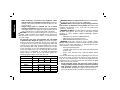 6
6
-
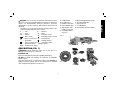 7
7
-
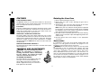 8
8
-
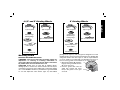 9
9
-
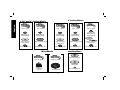 10
10
-
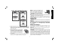 11
11
-
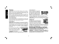 12
12
-
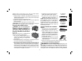 13
13
-
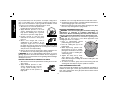 14
14
-
 15
15
-
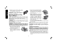 16
16
-
 17
17
-
 18
18
-
 19
19
-
 20
20
-
 21
21
-
 22
22
-
 23
23
-
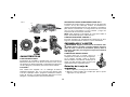 24
24
-
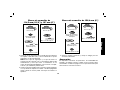 25
25
-
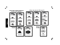 26
26
-
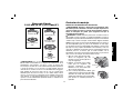 27
27
-
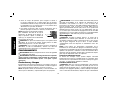 28
28
-
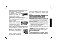 29
29
-
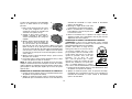 30
30
-
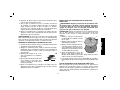 31
31
-
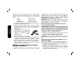 32
32
-
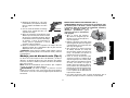 33
33
-
 34
34
-
 35
35
-
 36
36


DeWalt D28114 Manual de usuario
- Categoría
- Herramientas eléctricas
- Tipo
- Manual de usuario
En otros idiomas
- English: DeWalt D28114 User manual
Documentos relacionados
-
DeWalt DW818 Manual de usuario
-
-
-
Epson D28402B Manual de usuario
-
-
DeWalt DWE4120N Manual de usuario
-
DeWalt D28402 Manual de usuario
-
-
DeWalt DW840 Manual de usuario
-