
SML
V1
20170922
ES-EN-FR
GANCHO PESADOR
CRANE SCALE
CROCHET PESEUR
SML
El fabricante se reserva el derecho de modificar sin previo aviso las características de sus productos para introducir mejoras técnicas o cumplir con nuevas regulaciones oficiales./Le
constructeur se réserve le droit de modifier les caractéristiques de ses produits en vue d’y apporter des améliorations techniques ou de respecter de nouvelles réglamentations./The
manufacturer reserves the right to modify the specifications of its products in order to make technical improvements or comply with new regulations.
marca propiedad de | est une marque de | trade mark propiety of:
Pol. Empordà Internacional Calle F. Parcela 15-16
17469 VILAMALLA - (Girona) SPAIN
T. (34) 972 527 212 - F. (34) 972 527 211

ESPAÑOL 3
INGLISH 15
FRANÇAIS 27

3
BR95
ES
1. DATOS TÉCNICOS 4
2. DIMENSIONES (MM) 4
3. RECOMENDACIONES GENERALES DE SEGURIDAD 5
3.1 COMO COLGAR EL GANCHO PESADOR DE LA GRÚA 5
3.2 COMO CARGAR EL GANCHO PESADOR 5
3.3 CONDICIÓN PRELIMINAR 6
4. GANCHO PESADOR SML 7
4.1 DESCRIPCIÓN 7
4.2 PANTALLA 7
4.3 TECLADO 8
4.4 CONTROL REMOTO POR RADIO 8
5. USO 8
5.1 ENCENDER 8
5.2 APAGAR 8
5.3 PUESTA A CERO DEL GANCHO PESADOR 9
5.4 TARAR 9
5.5 PESAJE 9
5.6 MODO DE STANDBY 9
6. MENÚ DE AJUSTES 10
6.1 DESCRIPCIÓN DEL MENÚ 10
7. CALIBRACIÓN (SOLO PARA PERSONAL AUTORIZADO) 11
8. MENSAJES DE ERROR 12
9. MANTENIMIENTO, REPARACIÓN, LIMPIEZA Y TRATAMIENTO DE RESIDUOS 13
9.1 LIMPIEZA Y TRATAMIENTO DE RESIDUOS 13
11. GARANTÍA 13
ÍNDICE

ESMANUAL DE USUARIO SML
4
1. DATOS TÉCNICOS
Precisión de lectura (d) 0,5 kg 1 kg 2 kg
Rango de pesaje (máx.) 1500kg 3000kg 6000kg
Rango de tara (substractivo) 1500 kg 3000 kg 5000 kg
Pesa de calibración recomendada,
no incluida 1t (M1) 3t (M1) 5t (M1)
Tiempo de calentamiento 30min.
Unidad kg
Rango de temperatura -10°C ~ +40°C
Tensión de entrada adaptador 100–240 V AC 50/60 Hz
Tensión de salida adaptador 12V 500mA
Batería 6 V 10 Ah
Pantalla Tiempo de uso 60h
Tamaño de la carcasa (mm) Tiempo de carga 24 horas 300 x 190 x 230
Material del gancho y del grillete 5 dígitos de 30mm
Peso neto (kg) 14 18 23
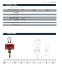
2. DIMENSIONES
Cap. (kg) A B C D E F G
1500 265 170 195 60 55 40 613
3000 300 190 230 75 76 45 740
6000 300 190 230 95 80 50 860

5
ESMANUAL DE USUARIO SML
3. RECOMENDACIONES GENERALES DE SEGURIDAD
¡Peligro de daños causados por las cargas en caída!
Trabajar siempre extremando las medidas de seguridad y conforme a los principios de manejo de la grúa.
Verificar el adecuado nivel de desgaste de todos los elementos (gancho, grillete, anillos, cuerdas de eslingas de
cuerda, cables, cadenas etc.).
No usar el gancho pesador si la lengüeta de seguridad está dañada o ausente.
Trabajar con la velocidad adecuada.
Terminantemente prohibido que la carga bascule o que operen fuerzas horizontales. Evitar cualquier tipo de golpe,
torsión (giro) o oscilación (p. ej. en caso de estar colgado el gancho pesador de forma inclinada).
No usar el gancho pesador para el transporte de carga.
No permanecer ni pasar bajo las cargas suspendidas.
No usar en la obra.
Vigilar siempre la carga suspendida.
No sobrepasar la carga nominal de la grúa, del gancho pesador o de cualquier dispositivo de enganche de carga;
Durante el pesaje de substancias peligrosa (p. ej. masas fundidas, material radioactivo) se han de respectar las
normas relativas a la manipulación de sustancias peligrosas!
3.1 COMO COLGAR EL GANCHO PESADOR DE LA GRÚA
Para obtener correctos resultados de pesaje es necesario respetar siguientes recomendaciones:
• Usar únicamente aparatos de colgar la carga que aseguren una suspensión del gancho pesador por un sólo punto.
• No usar aparatos para colgar la carga demasiado grandes, que no aseguren una suspensión del gancho pesador por un sólo punto.
• No usar eslingas múltiples.
• No arrastrar ni desplazar cargas con el gancho pesador.
• No arrastrar el gancho pesador horizontalmente.
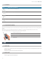
3.2 COMO CARGAR EL GANCHO PESADOR
1. Colocar el gancho pesador por encima de la carga.
2. Bajar el gancho pesador hasta que sea posible colgar la carga de su gancho.
Alcanzada la altura deseada, reducir la velocidad.
3. Colgar la carga del gancho. Asegurarse que la lengüeta de seguridad se cerró
correctamente.
En el caso de colocar la carga mediante eslingas de cuerda asegurarse que la
eslinga esté colocada bien en el centro del gancho.
4. Subir la carga lentamente. En el caso de colocar la carga mediante eslingas
de cuerda asegurarse
que la carga esté bien equilibrada y la eslinga esté bien colocada.

ESMANUAL DE USUARIO SML
6
3.3 CONDICIÓN PRELIMINAR
El gancho de la grúa ha de estar equipado con la lengüeta de seguridad (1) que impida la caída del gancho pesador.
Si la lengüeta falta o está dañada, contactar con el fabricante de la grúa para conseguir el gancho adecuado.
• Colgar el gancho pesador en el gancho inferior de la grúa y cerrar la lengüeta de seguridad.
El grillete superior del gancho pesador ha de permanecer en el interior del gancho de la grua (2).
Usar únicamente aparatos para colgar la carga que aseguren una
suspensión del gancho pesador por un sólo punto.
No usar aparatos para colgar la carga demasiado grandes que
no aseguren una suspensión del gancho pesador por un punto.
No desplazar ni arrastrar.
No tirar del gancho hacía un lado.
No usar eslingas múltiples.

7
ESMANUAL DE USUARIO SML
4. GANCHO PESADOR SML
El gancho pesador es una solución universal y económica que encuentra su utilidad siempre y cuando el pesaje tenga lugar por encima de la
cabeza del operador, p. ej. en la cadena de reciclaje y tratamiento de metales, construcción de maquinaria, transporte y logística.
Su uso mediante un control remoto es aún más cómodo.
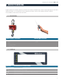
4.1 DESCRIPCIÓN
GANCHO PESADOR - VISTA FRENTE CONTROL REMOTO POR RADIO
1. Grillete 6. Antena
2. Pantalla 7. Teclado
3. Teclado
4. Lengüeta de seguridad
5. Enganche, giratorio
4.2 PANTALLA
INDICACIÓN LA INDICACIÓN LED SE ILUMINA CUANDO
Indicación de peso neto
Indicación de que el peso es estable
Indicación de que la masa se encuentra en el punto de peso cero
Batería está cargándose

ESMANUAL DE USUARIO SML
8
4.3 TECLADO
TECLA DESCRIPCIÓN DE LA FUNCIÓN
Encender / Apagar el gancho pesador
Tarar / x10(con pulsación larga)
Modo reposo (standby) / Modo normal
Poner a cero
4.4 CONTROL REMOTO POR RADIO
El control remoto por radio permite el uso del gancho como si fuera desde el teclado. El operador puede elegir cualquier opción
(menos ON/OFF).
Tras cada uso de una tecla, el diodo rojo LED ha de encenderse. En el caso contrario es necesario cambiar la pila del control remoto.
El alcance del control remoto en espacio diáfano es de aproximadamente 20 m.
1 Cambio de precisión de lectura
2 Poner a cero
3 Fijación del valor de la tara
4 Modo de standby
5. USO
5.1 ENCENDER
Presionar la tecla . El display se encenderá y el gancho pesador procederá al autodiagnóstico. El autodiagnóstico está terminado cuando en el display
aparezca el valor de masa 0kg.
El apagado es posible únicamente mediante el teclado del gancho pesador
5.2 APAGAR
Presionar la tecla en el teclado del gancho pesador.

9
ESMANUAL DE USUARIO SML
5.3 PUESTA A CERO DEL GANCHO PESADOR
Para obtener resultados correctos de pesaje, antes de proceder al pesaje es necesario poner a cero el gancho pesador.
Descargar el gancho pesador.
Presionar la tecla si el display no se encuentra ya a cero
En el display aparecerá el valor 0 (kg) y estará encendido el diodo LED 0
5.4 TARAR
Colgar la carga a tarar.
En el display aparecerá el valor 0 (kg) y está encendido el diodo LED de la indicación NET. La masa del contenedor está grabada en la memoria del
gancho pesador
Colgar el material a pesar. La masa indicada corresponde a su masa neta.
Una vez la carga de tara es quitada, la pantalla indicará su valor de masa en negativo.
Para suprimir la indicación de la tara, descargar el gancho pesador de grúa y presionar la tecla .
5.5 PESAJE
Cargar el gancho pesador.
Aparecerá inmediatamente el valor de la masa. Después de un correcto control de estabilización el diodo LED de indicación de estabilidad ,
estará encendido.
Advertencia ante la carga excesiva
Evitar cualquier sobrecarga del gancho pesador por encima de la carga máxima (máx.), incluyendo la carga que implica
la tara. Si no, el gancho pesador puede sufrir daños.
La indicación -OL- informa de la sobrecarga por encima de valores permitidos. Descargar el gancho pesador o disminuir
la carga inicial.
5.6 MODO DE STANDBY
El gancho pesador entra en el modo de standby se presiona la tecla .
En ese momento, un único segmento está encendido. Para salir del modo de standby pulsar de nuevo la tecla del teclado o del control remoto.
Existe la posibilidad de elegir entre diferentes tiempos de auto standby: 0, 5, 10, 20, 30 minutos. Para ello debe acceder al menú de ajustes y cambiar
el valor del parámetro F5.

ESMANUAL DE USUARIO SML
10
6. MENÚ DE AJUSTES
Acceder al menú
Encender el gancho pesador y durante el autodiagnóstico presionar simultáneamente las teclas y
Aparecerá el mensaje P1 - - -. Introducir su contraseña 000 por defecto
Mediante la tecla elegir los dígitos en edición y mediante la tecla incrementar el dígito parpadeante. Confirmar con la tecla
Selección de la función
La tecla permite navegar entre las funciones
Acceder a una función
La tecla permite acceder a la función que se está mostrando en pantalla
Cambio de ajustes
La tecla permite modificar los ajustes que se está mostrando en pantalla
Confirmar ajustes
La tecla permite confirmar los cambios realizados en la función y volver al menú de funciones.
Salida de la función / menú
La tecla permite volver al menú de funciones sin guardar los cambios realizados. O bien salir del menú y volver al modo de pesaje, si usted ya se
encotraba en el menú de funciones
6.1 DESCRIPCIÓN DEL MENÚ:
No modifique los parámetros bloqueados por el interruptor de calibración si no es estrictamente necesario. Una mala configuración de
estos puede provocar un mal funcionamiento del equipo.
F1 bt Velocidad de transmisión RS-232 sin función
F2 SP Velocidad del convertidor analógico digital (parámetro bloqueado por interruptor de calibración)
S 1 7,5 veces/segundo valor por defecto
S 2 15 veces/segundo
S 3 30 veces/segundo
S 4 60 veces/segundo
S 5 90 veces/segundo
F3 iP Cuentas internas
Muestra el valor de los puntos internos del convertidor
F4 Ut Unidad de pesaje (parámetro bloqueado por interruptor de calibración)
Ut oF quilos valor por defecto
Ut Lb libras
Ut tJ taels

11
ESMANUAL DE USUARIO SML
F5 SL Auto standby
Selección del tiempo de auto reposo (standby)
SLP 0 Sin modo reposo automático
SLP 1 Activará el modo reposo transcurridos 5 minutos sin carga.
SLP 2 Activará el modo reposo transcurridos 10 minutos sin carga.
SLP 3 Activará el modo reposo transcurridos 20 minutos sin carga.
SLP 4 Activará el modo reposo transcurridos 30 minutos sin carga.
F6 Gv Gravedad (parámetro bloqueado por interruptor de calibración)
Introduzca la gravedad de destino si es distinta de la de calibración
Mediante la tecla elija los dígitos en edición, mediante la tecla incremente el dígito parpadeante.
Confirme con la tecla 0
F7 Ci Nuevo password
Introduzca la nueva contraseña para acceder a los parámetros.
Mediante la tecla elija los dígitos en edición, mediante la tecla incremente el dígito parpadeante.
Confirme con la tecla
F8 CL CALIBRACIÓN (parámetro bloqueado por interruptor de calibración)
7. CALIBRACIÓN (SOLO PARA PERSONAL AUTORIZADO)
La calibración sólo puede ser efectuada por el personal técnico autorizado, por favor, si desea efectuar una
calibración contacte con su organismo de calibración autorizado para precintar y desprecintar la balanza. En el
caso de equipos verificados, la rotura del precinto conlleva la perdida de la verificación.
Acceder al menú de ajustes F8, siguiendo el procedimiento descrito en el apartado anterior.
Presionar una vez el botón interno de calibración.
Acceder al parámetro mediante la tecla
El equipo pedirá de nuevo la contraseña (000 por defecto), mediante la tecla Zzz elegir los dígitos en edición y mediante la tecla T
incrementar el dígito parpadeante.
Confirmar con la tecla
En el display aparecerá el mensaje “UnLD”.
Descargar el gancho pesador y esperar hasta que se encienda el diodo LED de la indicación de estabilidad .
Presionar la tecla . Aparecerá la masa de calibrado ajustada actualmente.
Para proceder a algún cambio, elegir el dígito a modificar mediante la tecla y cambiar su valor mediante la tecla . El dígito que
parpadea es el dígito activo.

ESMANUAL DE USUARIO SML
12
Validar mediante la tecla 0.
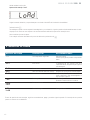
Aparecerá el mensaje “Load”
Colgar la masa de calibración y esperar hasta que se encienda el diodo LED de la indicación de estabilidad
Presionar la tecla
Tras realizarse un ajuste correcto empezará el autodiagnóstico y, a continuación, el gancho pesador volverá automáticamente al modo
de pesaje. En el caso de un error de ajuste o de una masa errónea de calibración, aparecerá el mensaje de error.
Volver a realizar el proceso de ajuste.
Si en cualquier momento desea abortar el proceso de calibración, presione la tecla .
8. MENSAJES DE ERROR
MENSAJE DE ERROR DESCRIPCIÓN RECOMENDACIONES
----- Se ha superado la carga límite Disminuir la carga.
Verificar que el gancho pesador no haya sufrido
daños
Err 4 Error de cero La desviación del cero excede el 4% de la
capacidad máxima. Asegúrese de que el gancho
esté descargado
Err 5 Error del teclado Compruebe las teclas
Err 6 Valor del convertidor A/D fuera de rango Asegúrese de que el gancho esté descargado
Err 9 Lectura inestable Compruebe que no haya fuertes corrientes de
viento, vibraciones, ruido electromagnético o
algo que toque el gancho
--oL-- Sobrecarga Quite la carga
Recalibre si esta era inferior a la máxima
Fail H
Fail L Error de calibración Recalibre
bA Lo
Lo bA Batería descargada. Recargar la bateria
En caso de aparición de estos mensajes, seguir las recomendaciones, apagar y encender el gancho pesador. Si el mensaje de error persiste,
ponerse en contacto con su distribuidor.

13
ESMANUAL DE USUARIO SML
9. MANTENIMIENTO, REPARACIÓN, LIMPIEZA Y TRATAMIENTO DE RESIDUOS
¡Peligro de sufrir daños o provocar daños materiales!
¡El gancho pesador de grúa es parte de la grúa!
Para un manejo seguro del aparato observar las normas siguientes:
Encomendar el mantenimiento periódico únicamente al personal especializado y formado.
Proceder al mantenimiento periódico y reparaciones necesarias,
Encomendar la sustitución de piezas únicamente al personal especializado y formado.
No permitir la utilización del gancho pesador si se han constatado problemas en la lista de
control de seguridad.
No repare el gancho pesador por sí mismo. Únicamente los servicios técnicos autorizados
pueden proceder a reparaciones.
9.1 LIMPIEZA Y TRATAMIENTO DE RESIDUOS
Atención puede dañar el gancho pesador de grúa!
No usar ningún disolvente industrial ni preparados químicos.
10. GARANTÍA
Este gancho está garantizado contra todo defecto de fabricación y de material, por un periodo de 1 año a partir de la fecha de entrega.
Durante este periodo, BAXTRAN se hará cargo de la reparación del equipo.
Esta garantía no incluye los daños ocasionados por uso indebido o sobrecargas.
La garantía no cubre los gastos de envío (portes) necesarios para la reparación del gancho pesador.

SML

15
ENUSER’S MANUAL SML
EN
1. TECHNICAL DATA 16
2. DIMMENSIONS (MM) 16
3. GENERAL SECURITY GUIDELINES 17
3.1 HOW TO HANG THE WEIGHING HOOK OF THE CRANE 17
3.2 HOW TO LOAD THE WEIGHING HOOK 17
3.3 PRELIMINARY CONDITION 18
4. SML WEIGHING HOOK 19
4.1 DESCRIPTION 19
4.2 DISPLAY 19
4.3 KEYBOARD 20
4.4 RADIO REMOTE CONTROL 20
5. USE 20
5.1 SWITCH ON 20
5.2 SWITCH OFF 20
5.3 RESET TO ZERO THE WEIGHING HOOK 21
5.4 TARING 21
5.5 WEIGHING 21
5.6 STAND BY MODE 21
6. SETTINGS MENU 22
6.1 DESCRIPTION OF THE MENU 22
7. CALIBRATION ( ONLY AVAILABLE TO AUTHORISED PERSONNEL) 23
8. ERROR MESSAGES 24
9. MAINTENANCE, REPAIRING, CLEANING AND TREATMENT OF WASTE 25
9.1 CLEANING AND TREATMENT OF WASTE 25
11. WARRANTY 25
INDEX

ENUSER’S MANUAL SML
16
1. TECHNICAL DATA
Reading Accuracy (d) 0,5 kg 1 kg 2 kg
Range of weighing (máx.) 1500kg 3000kg 6000kg
Range of tare (substractivo) 1500 kg 3000 kg 5000 kg
Recommended calibration weighing,
not included
1t (M1) 3t (M1) 5t (M1)
Warm-up time 30min.
Unit kg
Temperature range -10°C ~ +40°C
Input voltage adapter 100–240 V AC 50/60 Hz
Output voltage adapter 12V 500mA
Battery 6 V 10 Ah
Usage time Usage time 60h
Housing size (mm) Time of loading 24 hours 300 x 190 x 230
Material of the hook and the shackle 5 digits of 30mm
Net weight (kg) 14 18 23
2. DIMENSIONS
Cap. (kg) A B C D E F G
1500 265 170 195 60 55 40 613
3000 300 190 230 75 76 45 740
6000 300 190 230 95 80 50 860

17
ENUSER’S MANUAL SML
3. GENERAL SECURITY GUIDELINES
Danger of damages caused by the loads when falling!
Always work with extreme security measures and according to the principle of management of the crane.
Verify the appropriate level of wear of all the elements ( hook, shackle, rings, ropes of rope slings, cables, chains, etc)
Do not use the weighing hook when the safety catch is damaged or there isn’t any safety catch.
Work at the appropriate speed
It is completely forbidden to let the load tilt or to let horizontal forces operate. Avoid any type of hit, torsion (twist) or oscilla-
tion( for example when the weighing hook is hanged in a diverted way)
Do not use the weighing hook for cargo transport
Do not linger or walk under suspended loads
Do not use in construction work
Always verify suspended load
Do not exceed the nominal load of the crane, the weighing hook and any other towing device of the load
During the weighing of dangerous substances ( for example fused masses, radioactive material) the rules referring to the
handling of dangerous substances must be respected.
3.1. HOW TO HANG THE WEIGHING HOOK OF THE CRANE
To obtain the correct results of weighing it is necessary to respect the following recommendations:
• Use only the devices to hang the load that ensure the suspension of the weighing hook by only one fastening point.
• Do not use devices which are too big to hand the load, devices which do not ensure the suspension of the weighing hook
by only one fastening point.
• Do not use multiple slings.
• Do not drag or move loads with the weighing hook.
• Do not drag the weighing hook horizontally
3.2 HOW TO LOAD THE WEIGHING HOOK
1. Place the weighing hook over the load
2. Lower the weighing hook until it is possible to hang the load on its hook. When
you reach the desired height, reduce the speed.
3. Place the load on the hook. Make sure that the safety catch has been closed
correctly.
If you place the load using sling ropes make sure that the sling is placed correctly
in the centre of the hook.
4. Upload the load slowly. If you place the load using sling ropes make sure that
the load is well-balanced and the sling is correctly placed.

ENUSER’S MANUAL SML
18
3.3 PRELIMINARY CONDITION
The hook of the crane must be equipped with the safety catch (1) which prevents the falling of the weighing hook. If the safety catch is missing
or is damaged, you must get in contact with the manufacturer of the crane to get the appropriate hook.
• Hang the weighing hook in the lower hook of the crane and close the safety catch. The upper shackle of the weighing hook must remain
inside the hook of the crane (2).
To hang the load use only devices that ensure the suspension of
the weighing hook by only one point.
To hang the load does not use devices which are too big if they do
not ensure the suspension of the weighing hook by only one point.
Do not move or drag.
Do not throw the hook towards one side.
Do not use multiple slings.

19
ENUSER’S MANUAL SML
4. WEIGHING HOOK SML
The weighing hook is a universal and economic solution that is always useful as long as the weighing takes place over the head of the operator;
for example, in the recycling chain and treatment of metals, machine construction, transport and logistics.
If it is used using a remote control it is even more comfortable and easy to use
4.1 DESCRIPTION
WEIGHING HOOK-FRONT VIEW REMOTE CONTROL VIA RADIO
1. Shackle 6. Aerial
2. Screen 7. Keyboard
3. Keyboard
4. Safety catch
5. Hook, rotating
4.2 SCREEN
INDICATION THE LED INDICATION LITS WHEN
Indication of the net weight
Indication that the weight is steady
Indication that the mass finds itself in the zero weight point
Battery is loading

ENUSER’S MANUAL SML
20
4.3 KEYBOARD
TECLA DESCRIPTION OF THE FUNCTION
Switch on/ switch off the weighing hook
Tare/ x10 ( with long press)
Stanby mode / Normal mode
Set to zero
4.4 RADIO REMOTE CONTROL
Radio remote control allows the same use of the hook as when it is being used via the keyboard. The operator can choose any option (apart from
ON/OFF).
After every use of a key, the red LED diode should switch on. Otherwise it is necessary to change the battery of the remote control.
The scope of diaphanous space reached by the remote control is of approximately 20m.
1 Change the reading accuracy
2 Set to zero
3 Fix the value of the tare
4 Standby mode
5. USE
5.1 SWITCH ON
Press the key . The display is going to switch on and the weighing hook is going to start the self-testing. The self-testing finishes when the value of mass
0kg appears on the display.
The switch off is only possible when using the keyboard of the weighing hook.
5.2 SWITCH OFF
Press the key in the keyboard of the weighing hook.

21
ENUSER’S MANUAL SML
5.3 RESET TO ZERO THE WEIGHING HOOK
To obtain the appropriate weighing results, before starting the weighing process it is necessary to reset to zero the weighing hook.
Unload the weighing hook.
Press the keyboard if the display has not already been reset to zero.
On the display you are going to see the value 0 (kg) and the LED diode 0 will be on.
5.4 TARE
Hang the load to do the tare
The display is going to show the value 0 (kg) and the LED diode is going to be on with the indication NET. The mass of the container is recorded in the
memory of the weighing hook
Hang the material to weigh. The mass that appears in the display corresponds to the net mass.
Once the user has removed the tare, the screen is going to indicate its mass value in negative.
To remove the indication of tare, unload the weighing hook of the crane and press the key .
5.5 WEIGHING
Load the weighing hook.
The value of the mass is going to appear immediately. After a correct control of stabilization the LED diode which indicates stability will be ON.
Overload warning
Avoid any type of overload on the weighing hook which surpasses its maximum load (max), including the load which
implies the tare. If the user does not respect the overload warning, the weighing hook might suffer damages.
The indication –OL-informs of overload, if the load is above the limit values. Download the weighing hook or reduce the
initial load.
5.6 STANDBY MODE
The weighing hook starts the standby mode by pressing the key .
At this point, there will be only one segment switched on. To exit from the standby mode the user must press the key of the keyboard or from the
remote control. There is the possibility to choose between the different times of standby: 0, 5, 10 20, 30 minutes. To do so the user must enter the
settings menu and change the parameter F5.

ENUSER’S MANUAL SML
22
6. SETTINGS MENU
Enter the menu
Switch on the weighing hook and during the self-testing press simultaneously the keys y
The message P1--- is going to appear on the screen. Introduce your password 000 by default
Using the key ….choose the digits in edition and using the key increase the flashing digit. Confirm with the key
Choosing the function
The key enables the user to navigate among the menu functions
Access to one function
The key enables the user to access to the function which is shown on the screen.
Change the adjustment
The key enables the user to access to the function which is shown on the screen.
Confirm adjustment
The key allows to the user to confirm the changes done in the function and go back to the functions menu
Exit the function/menu
The key allows to the user to go back to the functions menu without saving the changes done. Or exit the menu and go back to the weighing mode, if
the user is already in the functions menu.
6.1 MENU DESCRIPTION:
Do not modify the parameters blocked by the switch of calibration if it is not strictly necessary. A wrong configuration of them can lead
to malfunctions of the equipment.
F1 bt baud rate RS-232 without function
F2 SP Speed of the analogue digital converter ( parameter blocked by the calibration switch)
S 1 7,5 times/second default value
S 2 15 times/second
S 3 30 times/second
S 4 60 times/second
S 5 90 times/second
F3 iP Internal accounts
It shows the value of the internal points of the converter
F4 Ut Weighing Unit ( parameter blocked by the calibration switch)
Ut oF kilos default vaule
Ut Lb pounds
Ut tJ taels

23
ENUSER’S MANUAL SML
F5 SL Auto standby
Select the time of auto standby
SLP 0 Without automatic standby
SLP 1 It is going to activate the standby mode after 5 minutes without any load.
SLP 2 It is going to activate the standby mode after 10 minutes without any load.
SLP 3 It is going to activate the standby mode after 20 minutes without any load.
SLP 4 It is going to activate the standby mode after 30 minutes without any load.
F6 Gv Gravity ( parameter blocked by the calibration switch)
Introduce the gravity of destination if it is different from the calibration one.
Using the key choose the digits of edition, using the key you can increase the blinking digit. Confirm
your operation by pressing the key .
F7 Ci Nuevo password
Introduce the new password to acces to the paremeters.
Using the key choose the digits of edition, using the key you can increase the blinking digit. Confirm
your operation by pressing the key .
F8 CL CALIBRATION (parameter blocked by the calibration switch)
7. CALIBRATION ( ONLY AVAILABLE TO AUTHORISED PERSONNEL)
The calibration must be done only by authorised technical personnel. Please, if you want to do a calibration contact
with your calibration authorised organism to seal and unseal the scale. When the equipment has been verified, the
breaking of the seal implies the loss of the verification.
Access the settings menu F8, following the procedure described in the previous section.
Press once the internal key of calibration.
Access the parameter using the key
The equipment is going to ask for a password ( 000 by default), using the key the user can choose the digits of edition and using
the key T the user can increase the blinking digit.
Confirm using the key
The message “UnLD” is going to appear in the display.
Download the weighing hook and wait until the LED diode which indicates stability switches on.
Press the key It will appear the calibration mass correctly adjusted.
To proceed to do a change, choose the digit to modify by using the key and change its value by using the key . The digit
which is blinking it the active digit.

ENUSER’S MANUAL SML
24
Validate using the key 0.
It is going to appear the message “Load”
Hang the calibration mass and wait until the LED diode which indicates stability switches on.
Press the key
After having done the appropriate adjustment the self-testing is going to start. And next the weighing hook will automatically go back to
the weighing mode. If there is an adjustment error or a wrong mass of calibration, a message of error is going to appear on the screen.
If you want to leave the calibration process at any moment, please press the key .
8. ERROR MESSAGES
ERROR MESSAGE DESCRIPTION RECOMMENDATIONS
----- The limit of load has been exceeded Reduce the load.
Verify that the weighing hook has not suffered
any damages.
Err 4 Zero error The deviation of zero exceeds the 4% of the
maximum capacity. Make sure that the hook is
unloaded.
Err 5 Keyboard error Check the keys
Err 6 Value of the A/D converter out of range Make sure that the hook is unloaded.
Err 9 Unstable reading Check that there aren’t strong wind currents,
vibrations, electromagnetic noise or something
is touching the hook
--oL-- Overload Remove the load
Recalibrate if this was inferior to the maxim
Fail H
Fail L Error of calibration Recalibrate
bA Lo
Lo bA Discharged battery Recharge the battery
If these messages appear in the screen, you must follow the recommendations, switch off and switch on the weighing hook. If the error message
does not disappear, please contact your distributor.

25
ENUSER’S MANUAL SML
9. MAINTENANCE, REPAIR, CLEANING AND TREATMENT OF WASTES
Danger of suffering damages or cause material damages!
The weighing hook is a part of the crane!
For a correct handling of the device, please read, follow and bear in mind the
following rules:
Comment the regular maintenance of the device to only authorised and specialised personnel.
Do not allow the use of the weighing hook if there have been problems concerning the list of
the control of security.
Do not repair the weighing hook by your own means, contact with authorised technicians, only
them can proceed to do the repairing.
9.1 CLEANING AND WASTE TREATMENT
Attention, you can damage the weighing hook of the crane!
Do not use any industrial solvent or industrial chemicals.
10. WARRANTY
This hook is guaranteed against all manufacturing or material faults for a period of 1 year from the date of delivery.
During this period, BAXTRAN will take care of the repair of the equipment.
This guarantee does not include damages due to improper use or overload.
The guarantee does not cover the charge for post and packing necessary for the repair of the weighing hook.

SML

FRMANUEL D’UTILISATION SML
27
FR
1. CARACTÉRISTIQUES TECHNIQUES 28
2. DIMENSIONS (MM) 28
3. RECOMMANDATIONS GÉNÉRALES DE SÉCURITÉ 29
3.1 COMMENT SUSPENDRE LE CROCHET PESEUR DE LA GRUE 29
3.2 COMMENT CHARGER LE CROCHET PESEUR 29
3.3 CONDITION PRÉLIMINAIRE 30
4. CROCHET PESEUR SML 31
4.1 DESCRIPTION 31
4.2 ÉCRAN 31
4.3 CLAVIER 32
4.4 CONTRÔLE À DISTANCE PAR RADIO 32
5. UTILISATION 32
5.1 ALLUMER 32
5.2 ÉTEINDRE 32
5.3 MISE À ZÉRO DU CROCHET PESEUR 33
5.4 TARER 33
5.5 PESAGE 33
5.6 MODE STANDBY 33
6. MENU DE RÉGLAGES 34
6.1 DESCRIPTION DU MENU 34
7. CALIBRAGE (UNIQUEMENT POUR PERSONNEL AUTORISÉ) 35
8. MESSAGES D’ERREUR 36
9. ENTRETIEN, RÉPARATION, NETTOYAGE ET TRAITEMENT DE DÉCHETS 37
9.1 NETTOYAGE ET TRAITEMENT DES DÉCHETS 37
11. GARANTIE 37
INDEX

FRMANUEL D’UTILISATION SML
28
1. CARACTÉRISTIQUES TECHNIQUES
Précision de lecture (d) 0,5 kg 1 kg 2 kg
Rang de pesage (max.) 1500kg 3000kg 6000kg
Rang de tare (soustractif) 1500 kg 3000 kg 5000 kg
Poids de calibrage recommandé, 1t (M1) 3t (M1) 5t (M1)
non inclus 30min.
Durée de chauffe kg
Unité -10°C ~ +40°C
Plage de températures 100–240 V AC 50/60 Hz
Tension d’entrée adaptateur 12V 500mA
Batterie 6 V 10 Ah
Écran Tiempo de uso 60h
Taille de la carcasse (mm) Tiempo de carga 24 horas 300 x 190 x 230
Équipement du crochet et de la manille 5 dígitos de 30mm
Poids net (kg) 14 18 23
2. DIMENSIONS
Cap. (kg) A B C D E F G
1500 265 170 195 60 55 40 613
3000 300 190 230 75 76 45 740
6000 300 190 230 95 80 50 860

FRMANUEL D’UTILISATION SML
29
3. RECOMMANDATIONS GÉNÉRALES DE SÉCURITÉ
Risque de blessures provoquées par des chutes de charges !
Toujours travailler en renforçant les mesures de sécurité et conformément aux principes d’utilisation de la grue.
Vérifier le niveau adéquat d’usure de tous les éléments (crochet, manille, anneaux, cordes, élingues en corde,
câbles, chaînes, etc.).
Ne pas utiliser le crochet peseur si la languette de sécurité est abîmée ou absente.
Travailler à la vitesse adéquate.
Il est strictement interdit de faire basculer la charge ou qu’elle soit soumise à des forces horizontales. Éviter tous
types de coups, torsion (rotation) ou oscillation (par ex. si le crochet peseur est suspendu de manière inclinée).
Ne pas utiliser le crochet peseur pour le transport de charges.
Ne pas rester ni passer sous les charges suspendues.
Ne pas utiliser dans le chantier.
Toujours surveiller la charge suspendue.
Ne pas dépasser la charge nominale de la grue, du crochet peseur ou de n’importe quel dispositif d’accrochage de
la charge.
Durant le pesage de substances dangereuses (par ex. masses en fusion, matériel radioactif), les normes relatives à
la manipulation de substances dangereuses doivent être respectées !
3.1 COMMENT SUSPENDRE LE CROCHET PESEUR DE LA GRUE
Afin d’obtenir des résultats corrects de pesage, il est nécessaire de respecter les recommandations suivantes :
Pour suspendre la charge, utiliser uniquement des appareils qui assurent une suspension du crochet peseur par un seul point.
Pour suspendre la charge, ne pas utiliser d’appareils trop grands, n’assurant pas une suspension du crochet peseur par un seul point.
Ne pas utiliser d’élingues multiples.
Ne pas traîner ni déplacer des charges avec le crochet peseur.
Ne pas traîner le crochet peseur horizontalement.
3.2 COMMENT CHARGER LE CROCHET PESEUR
1. Placer le crochet peseur au-dessus de la charge.
2. Baisser le crochet peseur jusqu’à ce qu’il soit possible de suspendre la charge
à son crochet. Une fois la hauteur souhaitée atteinte, réduire la vitesse.
3. Suspendre la charge au crochet. S’assurer que la languette de sécurité est
fermée correctement.
Si l’on place la charge avec des élingues en corde, s’assurer que l’élingue est
bien suspendue au centre du crochet.
4. Monter la charge lentement. Si l’on place la charge avec des élingues en cor-
de, s’assurer que la charge soit bien équilibrée et l’élingue bien placée.

FRMANUEL D’UTILISATION SML
30
3.3 CONDITION PRÉLIMINAIRE
Le crochet de la grue doit être équipé de la languette de sécurité (1) empêchant la chute du crochet peseur. Si la languette manque ou qu’elle est
abîmée, contacter le fabricant de la grue afin d’obtenir un crochet adéquat.
• Suspendre le crochet peseur au crochet inférieur de la grue et fermer la languette de sécurité. La manille supérieure du crochet peseur
doit rester à l’intérieur du crochet de la grue (2).
Pour suspendre la charge, utiliser uniquement des appareils qui assu-
rent une suspension du crochet peseur par un seul point.
Pour suspendre la charge, ne pas utiliser d’appareils trop grands,
n’assurant pas une suspension du crochet peseur par un point.
Ne pas déplacer ni traîner.
Ne pas tirer sur le crochet vers un côté.
Ne pas utiliser d’élingues multiples.

FRMANUEL D’UTILISATION SML
31
4. CROCHET PESEUR SML
Le crochet peseur est une solution universelle et économique qui trouve son utilité lorsque le pesage ait lieu au-dessus de la tête de l’ouvrier. Par
ex. dans la chaîne de recyclage et le traitement de métaux, la construction de machines, le transport et la logistique.
Son utilisation par contrôle à distance est encore plus commode.
4.1 DESCRIPTION
CROCHET PESEUR - VUE DE FACE CONTRÔLE À DISTANCE PAR RADIO
1. Manille 6. Antenne
2. Écran 7. Clavier
3. Clavier
4. Languette de sécurité
5. Crochet giratoire
4.2 ÉCRAN
INDICATION L’INDICATION LED S’ÉCLAIRE QUAND
Indique le poids net
Indique que le poids est stable
Indique que la masse se trouve au point de poids zéro
La batterie est en charge

FRMANUEL D’UTILISATION SML
32
4.3 CLAVIER
CLAVIER DESCRIPTION DE LA FONCTION
Allumer/Éteindre le crochet peseur
Tarer / x10 (appuyer longuement)
Mode veille (standby) / Mode normal
Remettre à zéro
4.4 CONTRÔLE À DISTANCE PAR RADIO
Le contrôle à distance par radio permet l’utilisation du crochet comme s’il s’agissait du clavier. L’ouvrier peut choisir toute option (sauf ON/OFF).
Après l’utilisation d’une touche, la diode rouge LED doit s’allumer. Dans le cas contraire, il est nécessaire de changer la pile de contrôle à dis-
tance. La portée du contrôle à distance dans un espace ouvert est d’environ 20 m.
1 Changement de précision de lecture.
2 Remettre à zéro
3 Fixation de la valeur de la tare
4 Mode standby
5. UTILISATION
5.1 ALLUMER
Appuyer sur la touche . Le display s’allumera et le crochet peseur procédera à l’auto-diagnostique. L’auto-diagnostique est terminé quand la valeur de
masse 0 kg apparaît sur le display.
L’arrêt est possible uniquement par le clavier du crochet peseur.
5.2 ÉTEINDRE
Appuyer sur la touche du clavier du crochet peseur.

FRMANUEL D’UTILISATION SML
33
5.3 MISE À ZÉRO DU CROCHET PESEUR
Afin d’obtenir des résultats corrects de pesage, avant de procéder à celui-ci, il est nécessaire de remettre le crochet peseur à zéro.
Décharger le crochet peseur.
Appuyer sur la touche si le display n’est toujours pas à zéro.
La valeur 0 (kg) apparaîtra sur le display et la diode LED sera allumée 0
5.4 TARER
Suspendre la charge à tarer.
La valeur 0 (kg) apparaîtra sur le display et la diode LED de l’indication NET est allumée. La masse du conteneur est gravée sur la mémoire du crochet
peseur.
Suspendre le matériel à peser. La masse indiquée correspond à la masse nette.
Une fois la charge de tare enlevée, l’écran indiquera sa valeur de masse en négatif.
Pour supprimer l’indication de la tare, décharger le crochet peseur de la grue et appuyer sur la touche .
5.5 PESAGE
Charger le crochet peseur.
La valeur de la masse apparaître immédiatement. Après un contrôle correct de stabilisation, la diode LED , d’indication de stabilité sera allumée.
Avertissement face à la charge excessive
Éviter toute surcharge du crochet peseur au-dessus de la charge maximale (max.), y compris la charge qui implique la
tare. Sinon, le crochet peseur peut subir des dégâts.
L’indication -OL- informe de la surcharge au-dessus des valeurs permises. Décharger le crochet peseur ou diminuer la
charge initiale.
5.6 MODE DE STANDBY
Le crochet peseur entre en mode standby, on appuie sur la touche .
À ce moment-là, un segment unique est allumé. Pour quitter le mode standby, appuyer de nouveau sur la touche du clavier ou du contrôle à
distance. Il existe la possibilité de choisir entre différentes durées d’auto-standby : 0, 5, 10, 20, 30 minutes. Pour cela, il suffit d’accéder au menu de
réglages et changer la valeur du paramètre F5.

FRMANUEL D’UTILISATION SML
34
6. MENU DE RÉGLAGES
Accéder au menu.
Allumer le crochet peseur et pendant l’auto-diagnostique, appuyer simultanément sur les touches et
Le message P1 - - - apparaîtra. Introduire le mot de passe 000 par défaut.
Avec la touche choisir les chiffres en édition et avec la touche augmenter le chiffre clignotant. Confirmer avec la touche
Sélection de la fonction
La touche permet de naviguer entre les fonctions.
Accéder à une fonction
La touche permet d’accéder à la fonction qui apparaît sur l’écran.
Changement de réglages
La touche permet de modifier les réglages qui apparaissent sur l’écran.
Confirmer les réglages
La touche permet de confirmer les changements réalisés dans la fonction et revenir au menu des fonctions.
Sortie de la fonction / menu
La touche permet de revenir au menu des fonctions sans sauvegarder les changements réalisés. Ou bien sortir du menu et revenir au mode de pesage,
si vous vous trouviez déjà dans le menu des fonctions.
6.1 DESCRIPTION DU MENU :
Ne modifiez pas les paramètres bloqués par l’interrupteur de calibrage si ce n’est pas strictement nécessaire. Une mauvaise configuration
de ceux-ci peut provoquer un mauvais fonctionnement de l’appareil.
F1 bt Vitesse de transmission RS-232 sans fonction
F2 SP Vitesse du convertisseur analogique numérique (paramètre bloqué par l’interrupteur de calibrage)
S 1 7,5 fois/seconde valeur par défaut
S 2 15 fois/seconde
S 3 30 fois/seconde
S 4 60 fois/seconde
S 5 90 fois/seconde
F3 iP Comptes internes
Montre la valeur des points internes du convertisseur
F4 Ut Unité de pesage (paramètre bloqué par l’interrupteur de calibrage)
Ut oF kilos valeur par défaut
Ut Lb livres
Ut tJ taels

FRMANUEL D’UTILISATION SML
35
F5 SL Auto standby
Sélection du temps de veille automatique (standby)
SLP 0 Sans mode veille automatique
SLP 1 Activera le mode veille après 5 minutes sans charge.
SLP 2 Activera le mode veille après 10 minutes sans charge.
SLP 3 Activera le mode veille après 20 minutes sans charge.
SLP 4 Activera le mode veille après 30 minutes sans charge.
F6 Gv Gravité (paramètre bloqué par l’interrupteur de calibrage). Introduisez la gravité de destination si elle est
différente de celle du calibrage.
Avec la touche choisissez les chiffres en édition, avec la touche , augmentez le chiffre clignotant.
Confirmez
F7 Ci Nouveau mot de passe
Introduisez le nouveau mot de passe pour accéder aux paramètres.
Avec la touche choisissez les chiffres en édition, avec la touche incremente el dígito parpadeante.
Confirmez avec la touche
F8 CL CALIBRAGE (paramètre bloqué par l’interrupteur de calibrage)
7. CALIBRAGE (UNIQUEMENT POUR LE PERSONNEL AUTORISÉ)
Le calibrage doit être effectué uniquement par du personnel technique autorisé. Si vous souhaitez effectuer un
calibrage, veuillez contacter votre organisme de calibrage autorisé afin de sceller et desceller la balance. Si les
appareils sont vérifiés, la rupture du scellé entraîne la perte de la vérification.
Accéder au menu de réglages F8, en suivant la procédure décrite dans le paragraphe précédent. Appuyer une fois sur le bouton interne
de calibrage.
Accéder au paramètre par la touche
L’appareil demandera de nouveau le mot de passe (000 par défaut), avec la touche , choisir les chiffres en édition et avec la touche
T augmenter le chiffre clignotant.
Confirmer avec la touche .
Le message “UnLD” apparaîtra dans le display.
Décharger le crochet peseur et attendre jusqu’à ce que la diode LED de l’indication de la stabilité s’allume. Appuyer sur la touche
. La masse de calibrage ajustée actuellement apparaîtra.

FRMANUEL D’UTILISATION SML
36
Afin de procéder à un changement, choisir le chiffre à modifier avec la touche et changer sa valeur avec la touche . Le chiffre
qui clignote est celui qui est actif.
Valider avec la touche 0.
Le message « Load » apparaîtra.
Suspendre la masse de calibrage et attendre jusqu’à l’allumage de la diode LED de l’indication de stabilité.
Appuyer sur la touche
Après la réalisation d’un réglage correct, l’auto-diagnostique commencera et, ensuite, le crochet peseur reviendra automatiquement au
mode pesage. En cas d’erreur de réglage ou d’une masse erronée de calibrage, le message d’erreur apparaîtra.
Réaliser de nouveau le processus de réglage.
Si à tout moment vous souhaitez abandonner le processus de calibrage, appuyez sur la touche .
8. MESSAGES D’ERREUR
MESSAGE D’ERREUR DESCRIPTION RECOMMANDATIONS
----- La charge limite est dépassée. Diminuer la charge.
Vérifier que le crochet peseur n’ait pas subi de
dégâts.
Err 4 Erreur de zéro La déviation du zéro excède 4% de la capacité
maximale. Assurez-vous que le crochet est
déchargé.
Err 5 Erreur de clavier Vérifiez les touches.
Err 6 Valeur du convertisseur A/D hors de la
plage Assurez-vous que le crochet est déchargé.
Err 9 Lecture instable Vérifiez qu’il n’y ait pas de rafales de vent,
des vibrations, du bruit électromagnétique ou
quelque chose qui touche le crochet.
--oL-- Surcharge Ôtez la charge.
Recalibrez si celle-ci était inférieure à la
maximale.
Fail H
Fail L Erreur de calibrage Recalibrez
bA Lo
Lo bA Batterie déchargée Rechargez la batterie
En cas d’apparition de ces messages, suivre les recommandations, éteindre et allumer le crochet peseur. Si le message d’erreur persiste, con-
tactez votre revendeur.

FRMANUEL D’UTILISATION SML
37
9. ENTRETIEN, RÉPARATION, NETTOYAGE ET TRAITEMENT DE DÉCHETS
Risque de subir des dommages ou de provoquer des dégâts matériels !
Le crochet peseur de la grue est une partie de la grue !
Pour une manipulation sûre de l’appareil, veuillez lire les normes suivantes :
Uniquement confier l’entretien périodique au personnel spécialisé et formé. Procéder à
l’entretien périodique et aux réparations nécessaires.
Confier le changement des pièces uniquement au personnel spécialisé et formé.
Ne pas permettre l’utilisation de crochet peseur si vous avez constaté des problèmes dans la
liste de contrôle de sécurité.
Ne réparez pas le crochet peseur par vous-même. Seuls les services techniques autorisés
peuvent procéder aux réparations.
9.1 NETTOYAGE ET TRAITEMENT DES DÉCHETS
Attention ! Risque d’endommager le crochet peseur de la grue.
Ne pas utiliser de dissolvent industriel ni de préparations chimiques.
10. GARANTIE
Ce crochet est garanti contre tout défaut de fabrication et de matériel, pour une période d’un an à partir de la date de livraison. Pendant cette
période, BAXTRAN se chargera de la réparation de l’équipement.
Cette garantie n’inclut pas les dommages occasionnés par un usage inadéquat ou des surcharges.
La garantie ne couvre pas les frais d’envoi (ports) nécessaires pour la réparation du crochet peseur.

SML

SML

marca propiedad de | est une marque de | trade mark propiety of:
Pol. Empordà Internacional Calle F. Parcela 15-16
17469 VILAMALLA - (Girona) SPAIN
T. (34) 972 527 212 - F. (34) 972 527 211
-
 1
1
-
 2
2
-
 3
3
-
 4
4
-
 5
5
-
 6
6
-
 7
7
-
 8
8
-
 9
9
-
 10
10
-
 11
11
-
 12
12
-
 13
13
-
 14
14
-
 15
15
-
 16
16
-
 17
17
-
 18
18
-
 19
19
-
 20
20
-
 21
21
-
 22
22
-
 23
23
-
 24
24
-
 25
25
-
 26
26
-
 27
27
-
 28
28
-
 29
29
-
 30
30
-
 31
31
-
 32
32
-
 33
33
-
 34
34
-
 35
35
-
 36
36
-
 37
37
-
 38
38
-
 39
39
-
 40
40


