Delphi YDT262 Operating And Servicing Manual
- Tipo
- Operating And Servicing Manual

HL018, Issue 2
YDT262
Dynamic Timing Control Box
(GB) Operating and Servicing Manual
(F) Manuel d’Utilisation et d’Entretien
(D) Bedienungs- und Wartungshandbuch
(E) Manual de Funcionamiento y Servicio
(I) Manuale di Utilizzo e Manutenzione
(P) Manual de Funcionamento e Manutencao
THIS IS AN UNCONTROLLED DOCUMENT downloaded by Lukas Matuska on 16 Feb 2016
Any technical intervention requires certified Hartridge training. Contact Hartridge Ltd for details.

YDT262 Operating and Servicing Manual DELPHI DIESEL AFTERMARKET
2 HL018, Issue 2
THIS IS AN UNCONTROLLED DOCUMENT downloaded by Lukas Matuska on 16 Feb 2016
Any technical intervention requires certified Hartridge training. Contact Hartridge Ltd for details.

DELPHI DIESEL AFTERMARKET YDT262 Operating and Servicing Manual
HL018, Issue 2 3
CONTENTS / TABLE DES MATIERES /
INHALTSVERZEICHNIS / INDICE
ENGLISH _______________________________________________________________________________ 5
FOREWORD _____________________________________________________________________________ 5
1. INTRODUCTION ______________________________________________________________________ 6
2. DEFINITION OF TERMS AND ABBREVIATIONS _______________________________________________ 6
3. PRINCIPLE OF OPERATION ______________________________________________________________ 6
4. OPERATION _________________________________________________________________________ 7
4.1 Layout ___________________________________________________________________________ 7
4.2 Installation ________________________________________________________________________ 7
4.3 Software Operating Sequence _________________________________________________________ 8
4.4 Setting / Overchecking the Timing Position _______________________________________________ 9
4.5 Downloading an Alternate Language ___________________________________________________ 9
5. SPARES AND SERVICE ________________________________________________________________ 11
5.1 YDT262 Spares ___________________________________________________________________ 11
5.2 Related Parts/Tools ________________________________________________________________ 11
5.3 Troubleshooting ___________________________________________________________________ 11
FRANCAIS _____________________________________________________________________________ 13
AVANT-PROPOS ________________________________________________________________________ 13
1. INTRODUCTION _____________________________________________________________________ 14
2. DÉFINITION DES EXPRESSIONS ET ABRÉVIATIONS ___________________________________________ 14
3. PRINCIPLE DE FONCTIONNEMENT _______________________________________________________ 14
4. FONCTIONNEMENT __________________________________________________________________ 15
4.1 Agencement ______________________________________________________________________ 15
4.2 Installation _______________________________________________________________________ 15
4.3 Séquence d'utilisation du logiciel ______________________________________________________ 16
4.4 Réglage / Surcontrôle de la position de distribution _______________________________________ 17
4.5 Téléchargement d'une autre langue ____________________________________________________ 17
5. PIÈCES DE RECHANGE ET RÉPARATIONS __________________________________________________ 20
5.1 Pièces de rechange pour le YDT262 ___________________________________________________ 20
5.2 Pièces connexes/Outillages __________________________________________________________ 20
5.3 Dépistage des anomalies ____________________________________________________________ 20
DEUTSCH _____________________________________________________________________________ 21
VORWORT _____________________________________________________________________________ 21
1. EINFÜHRUNG ______________________________________________________________________ 22
2. DEFINITION VON BEZEICHNUNGEN UND ABKÜRZUNGEN _____________________________________ 22
3. BETRIEBSPRINZIP ___________________________________________________________________ 22
4. BETRIEB ____________________________________________________________________________ 23
4.1 Layout __________________________________________________________________________ 23
4.2 Montage _________________________________________________________________________ 24
4.3 Betriebsabfolge der Software _________________________________________________________ 24
4.4 Einstellung / Überprüfen der Timingposition ____________________________________________ 25
4.5 Herunterladen einer zusätzlichen Sprache _______________________________________________ 25
5. ERSATZTEILE UND KUNDENDIENST ________________________________________________________ 28
5.1 Ersatzteile für das YDT262 __________________________________________________________ 28
5.2 Dazugehörige Teile/Werkzeuge _______________________________________________________ 28
5.3 Fehlersuche ______________________________________________________________________ 28
ESPAÑOL ______________________________________________________________________________ 29
PREFACIO _____________________________________________________________________________ 29
1. INTRODUCCIÓN _____________________________________________________________________ 30
2. DEFINICIÓN DE TÉRMINOS Y ABREVIACIONES ______________________________________________ 30
3. PRINCIPIO DE FUNCIONAMIENTO ________________________________________________________ 30
4. FUNCIONAMIENTO ____________________________________________________________________ 31
THIS IS AN UNCONTROLLED DOCUMENT downloaded by Lukas Matuska on 16 Feb 2016
Any technical intervention requires certified Hartridge training. Contact Hartridge Ltd for details.

YDT262 Operating and Servicing Manual DELPHI DIESEL AFTERMARKET
4 HL018, Issue 2
4.1 Disposición ______________________________________________________________________ 31
4.2 Instalación _______________________________________________________________________ 31
4.3 Secuencia de funcionamiento del programa _____________________________________________ 32
4.4 Ajuste y verificación de las posiciones de tiempos ________________________________________ 33
4.5 Carga de un idioma alternativo ______________________________________________________ 33
5. REPUESTOS Y MANTENIMIENTO __________________________________________________________ 35
5.1 Repuestos para el controlador YDT262 ________________________________________________ 35
5.2 Componentes y herramientas auxiliares ________________________________________________ 35
5.3 Localización y solución de problemas _________________________________________________ 35
ITALIANO ____________________________________________________________________________ 37
1. INTRODUZIONE _____________________________________________________________________ 38
2. DEFINIZIONE DEI TERMINI E ABBREVIAZIONI ______________________________________________ 38
3. PRINCIPIO OPERATIVO _______________________________________________________________ 38
4. FUNZIONAMENTO _____________________________________________________________________ 39
4.1 Disposizione _____________________________________________________________________ 39
4.2 Installazione _____________________________________________________________________ 39
4.3 Sequenza operativa del Software _____________________________________________________ 40
4.4 Impostazione /Controllo della posizione di fasatura _______________________________________ 41
4.5 Trasferimento di una lingua alternativa ________________________________________________ 41
5. RICAMBI E ASSISTENZA ________________________________________________________________ 43
5.1 Ricambi YDT262 __________________________________________________________________ 43
5.2 Parti / Attrezzi ____________________________________________________________________ 43
5.3 Ricerca guasti ____________________________________________________________________ 43
PORTUGES ____________________________________________________________________________ 45
PREFÁCIO _____________________________________________________________________________ 45
1. INTRODUÇÃO ______________________________________________________________________ 46
2. DEFINIÇÃO DOS TERMOS E ABREVIATURAS _______________________________________________ 46
3. PRINCÍPIO DE FUNCIONAMENTO ________________________________________________________ 46
4. OPERAÇÃO __________________________________________________________________________ 47
4.1 Disposição _______________________________________________________________________ 47
4.2 Instalação _______________________________________________________________________ 48
4.3 Sequência Operacional do Software ___________________________________________________ 48
4.4 Regulação / Verificação da Posição de Ponto ___________________________________________ 49
4.5 Carregamento de outra Língua ______________________________________________________ 49
5. PEÇAS SOBRESSALENTES E SERVIÇO ______________________________________________________ 51
5.1 Peças sobressalentes YDT262 ________________________________________________________ 51
5.2 Peças/Ferramentas Relacionadas _____________________________________________________ 51
5.3 Solução de Problemas ______________________________________________________________ 51
THIS IS AN UNCONTROLLED DOCUMENT downloaded by Lukas Matuska on 16 Feb 2016
Any technical intervention requires certified Hartridge training. Contact Hartridge Ltd for details.

DELPHI DIESEL AFTERMARKET YDT262 Operating and Servicing Manual
HL018, Issue 2 5
ENGLISH
Foreword
Copyright
DT Assembly & Test - Europe Ltd. reserves the copyright of all information and illustrations in this
publication which is supplied in confidence and which may not be used for any other purpose other
than that for which it was originally supplied. The publication may not be reproduced in part or in
whole without the consent in writing of this company.
© DT Assembly & Test - Europe Ltd.
Safety Information
The YDT262 is used in conjunction with a host test bench. Basic safety rules and precautions for
operating the host test bench should be observed.
Warnings, Cautions and Notes
The precautionary notes in this publication, indicated by the words WARNING, CAUTION, or NOTE
provide information about potential hazards to personnel or equipment. Ignoring these notes may
lead to serious injury to personnel and/or damage to equipment. These notes appear as follows:
WARNING! INDICATES THAT A SITUATION MAY BE HAZARDOUS TO PERSONNEL.
INSTRUCTIONS ARE PROVIDED FOR AVOIDING PERSONAL INJURY.
CAUTION! Indicates that conditions exist that could result in damage to equipment.
Instructions are provided to prevent equipment damage.
NOTE Indicates additional information for clarification where there may be confusion.
General Warnings
Ensure good levels of lighting for safe, efficient equipment operation.
Accidents can occur to unauthorised personnel during testing. Untrained
person(s) must not be present in the test area when the equipment is operating.
Only qualified personnel are to operate this equipment.
This equipment contains electrostatic sensitive devices. Observe the necessary
precautions for handling electrostatic discharge sensitive devices. Do not touch
printed circuit boards and associated electronic connections and components.
THIS IS AN UNCONTROLLED DOCUMENT downloaded by Lukas Matuska on 16 Feb 2016
Any technical intervention requires certified Hartridge training. Contact Hartridge Ltd for details.

YDT262 Operating and Servicing Manual DELPHI DIESEL AFTERMARKET
6 HL018, Issue 2
1. Introduction
The Dynamic Timing Control Box (YDT262) is used to determine the timing position of diesel fuel
injection pumps. It is used in conjunction with a host test bench (to mount and drive the fuel pump), a
rotary encoder (providing angular position information), and a piezo pickup (giving the point of
injection signal).
2. Definition of Terms and Abbreviations
The following terms and abbreviations are used in this manual and/or in the YDT262 software.
SP Start Position. The box records a reference point for starting position (effectively
0 degrees). This is used later when calculating the Overcheck Angle.
Offset The angular offset to be applied from the point of injection to the locking position.
Trigger Level The piezo signal trigger level at which the angular position is recorded.
POI Point of Injection
RLP Required Locking Position. This is equal to POI plus/minus the Offset.
Overcheck Angle The difference between SP and RLP.
3. Principle of Operation
The rotary encoder is mounted on the pump drive coupling and the piezo pickup is connected to one
of the pump delivery valves. The piezo pickup provides a signal once every revolution at the point of
injection. By comparing this signal with the angular position information from the rotary encoder, the
point of injection angle is found.
The actual position is found by taking a number of samples at a given speed. The software then
calculates the average position and, once the drive has been stopped, provides you with an angular
countdown so that you can rotate the pump around to that position.
THIS IS AN UNCONTROLLED DOCUMENT downloaded by Lukas Matuska on 16 Feb 2016
Any technical intervention requires certified Hartridge training. Contact Hartridge Ltd for details.

DELPHI DIESEL AFTERMARKET YDT262 Operating and Servicing Manual
HL018, Issue 2 7
4. Operation
4.1 Layout
Figure 4.1: Top View
Figure 4.1 Key:
1 2*20 display
2 Up (), Down (), and Enter () buttons
3 Piezo socket
4 Encoder socket
Figure 4.2: Bottom View
Figure 4.2 Key:
1 IEC Power inlet socket (accepts a range of standard connector leads).
2 On/Off Switch
3 120V/240V selector for nominal 115V/230V 50/60Hz AC single phase supply.
4 Power input fuse (2A anti-surge, 20mm*5mm)
5 RS232 connection
4.2 Installation
The YDT262 requires a standard IEC single-phase power lead, to be purchased locally. An EMC
shielding ferrite is supplied with the kit. Clip the ferrite onto the single-phase power lead as shown in
Figure 4.3.
CAUTION Set the 120V/240V voltage selector switch (Item 3, Figure 4.2) to the correct setting
for the local voltage.
1
2
4
3
5
3
4
1
2
THIS IS AN UNCONTROLLED DOCUMENT downloaded by Lukas Matuska on 16 Feb 2016
Any technical intervention requires certified Hartridge training. Contact Hartridge Ltd for details.

YDT262 Operating and Servicing Manual DELPHI DIESEL AFTERMARKET
8 HL018, Issue 2
Figure 4.3: Clip-on Ferrite
The YDT262 is designed to hang on the rim of the test stand. If using with Pumpmaster, AVM, or
PGM test stands, the additional adapter bracket will also be required.
4.3 Software Operating Sequence
The operating sequence for the box together with examples of the screen displays is given below.
Operating Step
Display Example
Power on
The display shows the version number and the last-used language.
Press Up/Down buttons to change language. Press Enter to
confirm and move on; the box records SP at this point.
VERSION 1.0
ENGLISH
Zero Angle Confirmation
The software confirms that the zero angle (SP) has been recorded.
Up/Down buttons disabled. Press Enter to confirm and move on.
If unsuccessful, the message “ZERO ANGLE ERROR” will be
displayed and all buttons will be disabled – refer to Section 5.3
Troubleshooting.
ZERO ANGLE
RECORDED
Offset Value
Display shows last-used offset value. Press Up/Down buttons to
change, scroll from 0.0 to 359.9 in steps of 0.1. Press Enter to
confirm and move on.
OFFSET:
0.0 DEG
Trigger level setting
Display shows last-used trigger level. Press Up/Down buttons to
change – the following levels are available: 25%, 50%, 72%, 75%
of peak voltage, or 100mV, 200mV, 400mV, 800mV. Press Enter to
confirm and move on.
TRIGGER LEVEL:
25%
Variation
Display shows the angle between piezo signals. This gives an
indication of any problems with the input signals (it should read
360 when the pump is running at constant speed). Press Enter
when value is stable and ready to test. Up/down buttons disabled.
VARIATION
359.8 DEG
Sampling
The box takes 100 samples of the piezo position, then calculates
RLP. All buttons are disabled during learning.
SAMPLING…
THIS IS AN UNCONTROLLED DOCUMENT downloaded by Lukas Matuska on 16 Feb 2016
Any technical intervention requires certified Hartridge training. Contact Hartridge Ltd for details.

DELPHI DIESEL AFTERMARKET YDT262 Operating and Servicing Manual
HL018, Issue 2 9
When complete, the display shows:
Press Enter to move on. Up/down buttons disabled.
PLEASE STOP
TEST BENCH
Overcheck Angle
The display shows the Overcheck Angle. Press Enter to move on.
Up/down buttons disabled.
OVERCHECK ANGLE:
2.10 DEG
Setting
The display shows the angle between the current position and RLP
(in direction of rotation). As the drive is rotated (by hand) the angle
displayed counts down to 0.
Up/down buttons disabled. Enter returns to offset screen.
ROTATE TO ZERO:
123.04 DEG
4.4 Setting / Overchecking the Timing Position
For details on setting and overchecking the timing position, refer to Delphi Service Instruction Note
number DT339.
4.5 Downloading an Alternate Language
The YDT262 is supplied pre-loaded with the following languages: English, French, German, Italian,
Spanish, and Portuguese. There is additional space allocated in the memory for one extra language,
which can be downloaded into the YDT262 from a PC.
When there is no additional language loaded the message “USER NOT AVALABLE” will appear when
you scroll through the languages. To escape from this message, press the Enter button.
To download an alternate language you will need the following:
Any PC with a serial communications program, e.g. Terminal or HyperTerminal (these are
standard programs supplied with Windows 3.x, 95, 98, and NT).
A standard 9-way D female to 9-way D female serial cable, e.g. RS Components part no. 215-
410.
Before downloading, you need to create the alternate language messages as a text file. An example
text file is given below (with English messages). Open Notepad and copy this example file,
translating where required. Note that each line can only have 20 characters maximum. Put 2
semicolons on the last line of the file as given in the example. Save the file and close Notepad.
Example language text file:
ENGLISH
FRENCH
GERMAN
ITALIAN
SPANISH
PORTUGUESE
USER
VERSION 1.2
TRIGGER LEVEL:
%
MV
OFFSET:
DEG
VARIATION
SAMPLING...
PLEASE STOP
TEST BENCH
THIS IS AN UNCONTROLLED DOCUMENT downloaded by Lukas Matuska on 16 Feb 2016
Any technical intervention requires certified Hartridge training. Contact Hartridge Ltd for details.

YDT262 Operating and Servicing Manual DELPHI DIESEL AFTERMARKET
10 HL018, Issue 2
OVERCHECK ANGLE
ROTATE TO ZERO
DEG
SEND TEXT
READY
USER NOT AVAILABLE
ZERO ANGLE
RECORDED
ZERO ANGLE
ERROR
;;
The procedure below refers to HyperTerminal. Other programs will be similar – the important
information is the COM port setup given in steps 4 and 5; refer to the operating instructions for your
particular program to set these.
1. Connect the cable between the YDT262 and one of the PC COM ports. Do not switch on the
YDT262 yet.
2. The first time you use HyperTerminal you will need to configure the communication settings. To
do this, open HyperTerminal (Start > Programs > Accessories > HyperTerminal > HyperTerminal).
It will assume you are making a new connection. Enter a name for the connection, e.g. YDT262,
choose an icon, then press OK.
3. In the next box select the COM port you are using and press OK.
4. In the next box, configure the port as follows, and then press OK. Baud: 9600; Data Bits: 8;
Parity: None; Stop Bits: 1; Flow Control: None.
5. Under ASCII setup (File, Properties, Settings, ASCII Setup), ensure that the “Send line ends with
line feeds” option is selected, then click OK twice to return to the main screen.
6. Choose File, Save. This saves the connection information as a HyperTerminal file, and puts a
link to it on the Start menu. Next time, you can just click on this link (Start > Programs >
Accessories > HyperTerminal > YDT262.ht) and it will open HyperTerminal with the correct
settings.
7. Switch on the YDT262 while holding down the Up and Down buttons. The message “SEND
TEXT” will appear on the display. You are now ready to transfer the language file.
8. In HyperTerminal select Transfer, Send Text File, and then browse to find your language text file
and select Open.
9. When the download is complete, the box will display “READY”. Press Enter to return to normal
operating mode.
THIS IS AN UNCONTROLLED DOCUMENT downloaded by Lukas Matuska on 16 Feb 2016
Any technical intervention requires certified Hartridge training. Contact Hartridge Ltd for details.

DELPHI DIESEL AFTERMARKET YDT262 Operating and Servicing Manual
HL018, Issue 2 11
5. Spares and Service
5.1 YDT262 Spares
The only serviceable parts in the YDT262 are the fuses.
There are two 1A fuses on the PCB itself (marked F1, F2), plus one 2A anti-surge fuse in the single-
phase socket. These are standard 5*20mm fuses that can be purchased locally.
WARNING! DISCONNECT THE ELECTRICAL SUPPLY BEFORE REMOVING THE COVER.
5.2 Related Parts/Tools
AE23 Aux Piezo Cable
26605 Piezo Sensor
AE24 2048ppr Auxiliary Encoder
7044-8 Coupling Extractor
7244-231 Drive Hub Extractor
AA1473 Coupling Spanner
5.3 Troubleshooting
The following table outlines procedures for dealing with simple problems. For anything not covered
here, or if the checks listed do not solve the problem, refer your national Delphi Distributor.
Symptom
Checks
A. YDT262 does not power up
1. Check the electrical supply.
2. Check the 120/240V selector switch is correctly set for the local supply.
3. Check the 3 fuses.
B. YDT262 powers up, but unexpected
messages/characters appear.
1. Switch off, wait a few seconds, then switch back on.
C. Variation screen shows 0 degrees, or is
not stable at 360 degrees.
1. Check the encoder is connected securely.
2. Check the piezo sensor and cable are connected securely.
3. Switch off, wait a few seconds, then switch back on.
D. “ZERO ANGLE ERROR” message
appears.
1. The pump drive shaft must be stationary to record the zero angle. Ensure
the pump is stationary when powering on the unit.
2. Switch off, wait a few seconds, then switch back on.
THIS IS AN UNCONTROLLED DOCUMENT downloaded by Lukas Matuska on 16 Feb 2016
Any technical intervention requires certified Hartridge training. Contact Hartridge Ltd for details.

THIS IS AN UNCONTROLLED DOCUMENT downloaded by Lukas Matuska on 16 Feb 2016
Any technical intervention requires certified Hartridge training. Contact Hartridge Ltd for details.

DELPHI DIESEL AFTERMARKET YDT262 Manuel d’utilisation et d’entretien
HL018, Issue 2 13
FRANCAIS
Avant-propos
Copyright
DT Assembly & Test - Europe Ltd. se réserve les copyrights de toutes les informations et de toutes
les illustrations contenues dans cette publication qui est fournie à titre confidentiel et qui ne doit pas
être utilisée à des fins autres que celles pour laquelle elle a été fournie à l'origine. Cette publication ne
doit pas être reproduite, en entier ou en partie, sans l'autorisation par écrit de cette société.
© DT Assembly & Test - Europe Ltd.
Consignes de sécurité
L'appareil YDT262 est utilisé en conjonction avec un banc d'essai récepteur. Il faut respecter les
règles et les précautions de sécurité élémentaires liées à l'utilisation du banc d'essai récepteur.
Avertissements, mises en garde et remarques
Les consignes de sécurité contenues dans cette publication et désignée par les mots
AVERTISSEMENT, ATTENTION ou REMARQUE donnent des informations sur les dangers
potentiels pour le personnel ou les équipements. Si ces consignes ne sont pas respectées, cela
risque d'entraîner des blessures graves pour le personnel et/ou des dégâts pour le matériel. Ces
consignes se présentent comme suit :
AVERTISSEMENT ! INDIQUE QU'UNE SITUATION RISQUE DE PRÉSENTER UN DANGER
POUR LE PERSONNEL. DES INSTRUCTIONS SONT FOURNIES AFIN
D'ÉVITER TOUT RISQUE DE BLESSURES CORPORELLES.
ATTENTION ! Indique qu'il existe des conditions susceptibles d'entraîner des dégâts
du matériel. Des instructions sont données pour éviter d'endommager le
matériel.
REMARQUE Donne des informations supplémentaires afin d'éclaircir certains points là où il
pourrait y avoir des confusions.
Avertissements généraux
S'assurer que le niveau d'éclairage est suffisant pour obtenir un fonctionnement
sûr et efficace du matériel.
Pendant les essais, il y a des risques d'accidents pour le personnel non autorisé.
Pendant le fonctionnement du matériel, il est impératif que toute personne non
formée soit éloignée de la zone d'essai. Seul le personnel qualifié doit faire
fonctionner ce matériel.
Ce matériel contient des dispositifs sensibles aux décharges électrostatiques.
Respecter les précautions nécessaires pour manipuler des dispositifs sensibles
aux décharges électrostatiques. Ne pas toucher aux circuits imprimés ni aux
connexions et composants électroniques connexes.
THIS IS AN UNCONTROLLED DOCUMENT downloaded by Lukas Matuska on 16 Feb 2016
Any technical intervention requires certified Hartridge training. Contact Hartridge Ltd for details.

YDT262 Manuel d’utilisation et d’entretien DELPHI DIESEL AFTERMARKET
14 HL018, Issue 2
1. Introduction
Le boîtier de commande de temporisation dynamique (YDT262) sert à établir la position de
distribution des pompes à injection de gazole. Il est utilisé en conjonction avec un banc d'essai
récepteur (pour monter et entraîner la pompe à carburant), un codeur rotatif (qui fournit des
informations sur la position angulaire) et un capteur piézoélectrique (qui donne le signal du point
d'injection).
2. Définition des expressions et abréviations
Les expressions et abréviations suivantes sont utilisées dans ce manuel et/ou dans le logiciel
YDT262.
PD Position de départ. Le boîtier enregistre un point de référence comme position
de départ (en fait, 0 degré). Ce point servira ultérieurement à calculer le
surcontrôle.
Offset L'offset angulaire à appliquer entre le point d'injection et la position de
verrouillage.
Seuil de tension Le seuil de tension du signal piézoélectrique où est enregistrée la position
angulaire.
PDI Point d'injection
PVR Position de verrouillage requise. Cette position est égale au point d'injection plus
ou moins l'offset.
Surcontrôle Différence entre la PD (Position de départ) et PVR (Position de verrouillage
requise).
3. Principle de fonctionnement
Le codeur rotatif est monté sur l'accouplement d'entraînement de la pompe et le capteur
piézoélectrique est relié à l'une des soupapes de refoulement de la pompe. Le capteur
piézoélectrique émet un signal une fois par tour, au point d'injection. En comparant ce signal avec les
informations sur la position angulaire transmises par le codeur rotatif, on peut trouver l'angle du point
d'injection.
Pour trouver la position réelle, on prend un certain nombre de relevés à une vitesse donnée. Le
logiciel calcule alors la position moyenne et, après l'arrêt de l'entraînement, il vous donne un débours
angulaire afin de vous permettre de faire tourner la pompe jusqu'à cette position.
THIS IS AN UNCONTROLLED DOCUMENT downloaded by Lukas Matuska on 16 Feb 2016
Any technical intervention requires certified Hartridge training. Contact Hartridge Ltd for details.

DELPHI DIESEL AFTERMARKET YDT262 Manuel d’utilisation et d’entretien
HL018, Issue 2 15
4. Fonctionnement
4.1 Agencement
Figure 4.1 : Vue du dessus
Figure 4.1 Légende :
1. Affichage de 2*20
2. Touches Haut (), Bas () et Entrer ()
3. Prise piézo
4. Prise codeur
Figure 4.2 : Vue du dessous
Figure 4.2 Légende :
1. Prise d'alimentation électrique IEC (accepte toute une gamme de fils de connecteur standards).
2. Commutateur Marche/Arrêt
3. Sélecteur 120 V/240 V pour une alimentation nominale monophasée 115 V/230 V 50/60 Hz c.a.
4. Fusible d'alimentation électrique (2 A contre les surtensions, 20 mm*5 mm)
5. Connexion RS232
4.2 Installation
Pour le YDT262, il faut prévoir un câble électrique monophasé IEC standard que vous pourrez vous
procurer localement. Un atténuateur de blindage à compatibilité électromagnétique en ferrite est
1
2
4
3
5
3
4
1
2
THIS IS AN UNCONTROLLED DOCUMENT downloaded by Lukas Matuska on 16 Feb 2016
Any technical intervention requires certified Hartridge training. Contact Hartridge Ltd for details.

YDT262 Manuel d’utilisation et d’entretien DELPHI DIESEL AFTERMARKET
16 HL018, Issue 2
fourni avec le kit. Encliquetez cet atténuateur sur le câble électrique monophasé comme illustré en
Figure 4.3.
ATTENTION Réglez le commutateur de tension 120 V/240 V (Poste 3, Figure 4.2) au réglage
correct correspondant à la tension du pays.
Figure 4.3 : Ferrite éclipsable
Le YDT262 est conçu pour être suspendu au bord du banc d'essai. Si vous utilisez le Pumpmaster
AVM ou les bancs d'essai PGM, il faudra prévoir en plus un support d'adaptation supplémentaire.
4.3 Séquence d'utilisation du logiciel
Vous trouverez ci-dessous la séquence d'utilisation du boîtier, ainsi que des exemples d'affichage à
l'écran.
Étape d'utilisation
Exemple d'affichage
Mise sous tension
L'écran indique le numéro de la version et la dernière langue utilisée.
Appuyez sur les touches Haut/Bas pour changer de langue.
Appuyez sur Entrer pour confirmer votre choix, puis passez à l'étape
suivante ; le boîtier enregistre la PD.
VERSION 1.0
FRANÇAIS
Confirmation de l'angle zéro
Le logiciel confirme que l'angle zéro (PD) a été enregistré. Touches
Haut/Bas désactivées. Appuyez sur Entrer pour confirmer et passer
à l'étape suivante.
En cas d'échec, le message “ERREUR ANGLE ZERO” s'affiche à
l'écran et toutes les touches sont désactivées. Reportez-vous au
paragraphe 5.3 "Dépistage des anomalies".
ANGLE ZERO
ENREGISTRE
Offset
L'affichage montre la dernière valeur d'offset utilisée. Appuyez sur
les touches Haut/Bas pour changer, défilez de 0.0 à 359.9 par
incréments de 0.1. Appuyez sur Entrer pour confirmer votre choix,
puis passez à l'étape suivante.
OFFSET :
0.0 DEG
THIS IS AN UNCONTROLLED DOCUMENT downloaded by Lukas Matuska on 16 Feb 2016
Any technical intervention requires certified Hartridge training. Contact Hartridge Ltd for details.

DELPHI DIESEL AFTERMARKET YDT262 Manuel d’utilisation et d’entretien
HL018, Issue 2 17
Réglage du seuil de tension
L'affichage montre le dernier niveau du seuil utilisé. Appuyez sur les
touches Haut/Bas pour changer. Les niveaux disponibles sont les
suivants : 25%, 50%, 72%, 75% de tension de pointe, ou 100 mV,
200 mV, 400 mV, 800 mV. Appuyez sur Entrer pour confirmer votre
choix, puis passez à l'étape suivante.
SEUIL DE TENSION :
25%
Variation
L'affichage montre l'angle entre les signaux piézo. Ceci donne une
indication de tous les problèmes éventuels concernant les signaux
d'entrée (lorsque la pompe fonctionne à vitesse constante, la lecture
affichée doit être de 360). Appuyez sur Entrer lorsque la valeur est
stable et prête à l'essai. Touches Haut/Bas désactivées.
VARIATION :
359.8 DEG
Prise des relevés
Le boîtier prend 100 relevés de la position piézo-électrique, puis
calcule la PVR. Toutes les touches sont désactivées pendant
l'apprentissage.
PRISE DES RELEVES…
Une fois terminé, le message suivant s'affiche à l'écran :
Appuyez sur Entrer pour passer à l'étape suivante.
ARRETEZ MOTEUR SVP
Touches Haut/Bas désactivées.
Surcontrôle
L'affichage indique le surcontrôle. Appuyez sur Entrer pour passer à
l'étape suivante. Touches Haut/Bas désactivées.
SURCONTROLE :
2.10 DEG
Réglage
L'affichage indique l'angle entre la position actuelle et la PVR (dans
le sens de la rotation). Lorsque vous faites tourner l'entraînement (à
la main), l'angle affiché diminue jusqu'à 0.
Touches Haut/Bas désactivées. Appuyez sur Entrer pour revenir à
l'écran Offset.
POSITIONNEZ AU ZERO :
123.04 DEG
4.4 Réglage / Surcontrôle de la position de distribution
Pour des renseignements détaillés sur le réglage et le surcontrôle de la position de distribution,
reportez-vous à la Note d'instructions de service Delphi numéro DT339.
4.5 Téléchargement d'une autre langue
L'appareil YDT262 est fourni déjà téléchargé du logiciel dans les langues suivantes : allemand,
anglais, espagnol, français, italien et portugais. Il y a de l'espace supplémentaire prévu dans la
mémoire pour une langue supplémentaire, que vous pourrez télécharger dans le YDT262 à partir d'un
ordinateur.
S'il n'y a pas de langue supplémentaire téléchargée, le message “PAS DISPONIBLE” s'affiche à
l'écran lorsque vous défilez dans la liste des langues. Pour sortir de ce message, appuyez sur la
touche Entrer.
Pour télécharger une autre langue, vous devez disposer du matériel suivant :
Un ordinateur avec un programme de communications en série, ex. Terminal ou HyperTerminal
(ces programmes sont fournis de série avec Windows 3.x, 95, 98 et NT).
Un câble série standard de femelle en D à 9 voies à femelle en D, ex. Composants RS nº de réf.
215-410.
THIS IS AN UNCONTROLLED DOCUMENT downloaded by Lukas Matuska on 16 Feb 2016
Any technical intervention requires certified Hartridge training. Contact Hartridge Ltd for details.

YDT262 Manuel d’utilisation et d’entretien DELPHI DIESEL AFTERMARKET
18 HL018, Issue 2
Avant de télécharger la langue, vous devez créer les messages dans la langue voulue sous forme de
fichier textuel. Un exemple de fichier textuel est illustré ci-dessous (les messages sont en anglais).
Ouvrez Notepad et copiez cet exemple de fichier, puis faites la traduction comme requis. À noter que
chaque ligne ne peut contenir que 20 caractères au maximum. Inscrivez 2 points virgules à la
dernière ligne, comme indiqué dans l'exemple. Sauvegardez ce fichier et fermez Notepad.
Exemple de fichier textuel pour télécharger une langue :
ENGLISH
FRENCH
GERMAN
ITALIAN
SPANISH
PORTUGUESE
USER
VERSION 1.2
TRIGGER LEVEL:
%
MV
OFFSET:
DEG
VARIATION
SAMPLING...
PLEASE STOP
TEST BENCH
OVERCHECK ANGLE
ROTATE TO ZERO
DEG
SEND TEXT
READY
USER NOT AVAILABLE
ZERO ANGLE
RECORDED
ZERO ANGLE
ERROR
;;
La procédure ci-dessous s'applique à HyperTerminal. Les autres programmes adopteront une
procédure similaire ; les informations importantes sont celles du paramétrage du port COM indiqué
aux paragraphes 4 et 5. Pour effectuer ce paramétrage, reportez-vous aux instructions d'utilisation
correspondant à votre programme particulier.
1. Connectez le câble entre l'appareil YDT262 et l'un des ports COM de l'ordinateur. N'allumez pas
encore le YDT262.
2. La première fois que vous utilisez HyperTerminal, vous devrez configurer les réglages de
communication. Pour cela, ouvrez HyperTerminal (Démarrage > Programmes > Accessoires >
HyperTerminal > HyperTerminal). Le système va supposer que vous faites une nouvelle
connexion. Entrez le nom de la connexion, ex. YDT262, choisissez une icône, puis appuyez sur
OK.
3. Dans la case suivante, sélectionnez le port COM que vous utilisez, puis appuyez sur OK.
4. Dans la case suivante, configurez le port comme suit, puis appuyez sur OK. Baud : 9600 ; Bits :
8 ; Parité : Néant ; Bits d'arrêt : 1 ; Contrôle de débit : Néant.
5. Dans le paramétrage ASCII (Fichier, Propriétés, Réglages, Paramétrage ASCII), vérifiez que
l'option “Send line ends with line feeds” (Envoyer fins de ligne avec changement de ligne) est
cochée, puis cliquez à deux reprises sur OK pour revenir à la page d'écran principale.
6. Choisissez File, Save (Fichier, Sauvegarder). Les informations sur la connexion sont alors
sauvegardées sous forme de fichier HyperTerminal, ce qui place un lien sur le menu de
Démarrage. La prochaine fois, il vous suffit de cliquer sur ce lien (Démarrage > Programmes >
THIS IS AN UNCONTROLLED DOCUMENT downloaded by Lukas Matuska on 16 Feb 2016
Any technical intervention requires certified Hartridge training. Contact Hartridge Ltd for details.

DELPHI DIESEL AFTERMARKET YDT262 Manuel d’utilisation et d’entretien
HL018, Issue 2 19
Accessoires > HyperTerminal > YDT262.ht) pour ouvrir HyperTerminal avec les paramétrages
corrects.
7. Allumez le YDT262 tout en maintenant enfoncées les touches Haut et Bas. Le message “SEND
TEXT” s'affiche à l'écran. Vous êtes alors prêt à passer au fichier de langue.
8. Dans HyperTerminal, sélectionnez Transfer, Send Text File, puis naviguez pour trouver votre
fichier textuel de langue, et sélectionnez Open.
9. Une fois le téléchargement terminé, la case affiche “READY”. Appuyez sur Entrer pour revenir au
mode d'utilisation normal.
THIS IS AN UNCONTROLLED DOCUMENT downloaded by Lukas Matuska on 16 Feb 2016
Any technical intervention requires certified Hartridge training. Contact Hartridge Ltd for details.

YDT262 Manuel d’utilisation et d’entretien DELPHI DIESEL AFTERMARKET
20 HL018, Issue 2
5. Pièces de rechange et réparations
5.1 Pièces de rechange pour le YDT262
Dans le YDT262, les seules pièces à changer sont les fusibles.
Il y a deux fusibles de 1 A sur la carte imprimée (marquée F1, F2), plus un fusible de 2 A de
protection contre les surtensions dans la prise monophasée. Il s'agit de fusibles standards 5*20 mm
que vous pourrez vous procurer localement.
AVERTISSEMENT ! AVANT DE RETIRER LE COUVERCLE, DÉBRANCHEZ L'ALIMENTATION
ÉLECTRIQUE.
5.2 Pièces connexes/Outillages
AE23 Câble piézo-électrique auxiliaire
26605 Capteur piézo-électrique
AE24 Codeur auxiliaire 2048 par paire
7044-8 Extracteur d'accouplement
7244-231 Extracteur de moyeu d'entraînement
AA1473 Clé d'accouplement
5.3 Dépistage des anomalies
Le tableau ci-dessous donne quelques procédures qui vous permettront d'éliminer les problèmes
simples. Pour toutes les anomalies non mentionnées ici, ou si les contrôles indiqués n'éliminent pas
le problème, veuillez vous adresser au distributeur Delphi de votre pays.
Symptôme
Contrôles
A. YDT262 ne s'allume pas
1. Vérifiez l'alimentation électrique.
2. Vérifiez que le commutateur 120/240 V est mis sur la tension correcte,
correspondant à celle de votre pays.
3. Vérifiez les 3 fusibles.
B. YDT262 s'allume, mais des
messages/caractères insolites s'affichent à
l'écran.
1. Éteignez, attendez quelques secondes, puis rallumez.
C. La page Variation indique 0 degré ou n'est
pas stable à 360 degrés.
1. Vérifiez que le codeur est fermement branché.
2. Vérifiez que le capteur et le câble piézo-électriques sont fermement
branchés.
3. Éteignez, attendez quelques secondes, puis rallumez.
D. Le message “ERREUR ANGLE ZERO”
s'affiche à l'écran.
1. L'arbre d'entraînement de la pompe doit être immobilisé afin
d'enregistrer l'angle zéro. Lors de la mise sous tension de l'appareil,
vérifiez que la pompe est immobilisée.
2. Éteignez, attendez quelques secondes, puis rallumez.
THIS IS AN UNCONTROLLED DOCUMENT downloaded by Lukas Matuska on 16 Feb 2016
Any technical intervention requires certified Hartridge training. Contact Hartridge Ltd for details.

DELPHI DIESEL AFTERMARKET YDT262 Bedienungs- und Wartungshandbuch
HL018, Issue 2 21
DEUTSCH
Vorwort
Urheberrecht
Alle in diesem Dokument enthaltenen Informationen und Abbildungen unterliegen dem
urheberrechtlichen Schutz. Sie sind vertraulich und dürfen nur für den Zweck verwendet werden, für
den sie ursprünglich geliefert worden sind. Ohne die schriftliche Zustimmung von DT Assembly &
Test - Europe Ltd. darf dieses Dokument weder ganz noch teilweise vervielfältigt werden.
© DT Assembly & Test - Europe Ltd.
Sicherheitsinformationen
Das YDT262 wird zusammen mit einem Prüfstand verwendet. Die grundlegenden Sicherheitsregeln
und –vorsichtsmaßnahmen für den Betrieb des Prüfstands sind zu beachten.
Vorsicht, Warnung und Hinweis
Die Warnhinweise und Instruktionen in diesem Dokument, die mit den Worten VORSICHT,
WARNUNG oder HINWEIS beginnen, warnen vor möglichen Gefahren für das Personal oder
Sachschäden. Ein Nichtbeachten dieser Warnhinweise kann zu schweren Verletzungen und/oder
Beschädigung des Geräts führen. Die Warnhinweise und Instruktionen werden wie folgt dargestellt:
VORSICHT! ZEIGT AN, DASS VERLETZUNGSGEFAHR BESTEHT, UND GIBT ANWEISUNGEN,
WIE VERLETZUNGEN VERMIEDEN WERDEN KÖNNEN.
WARNUNG! Zeigt an, dass die Gefahr der Beschädigung von Geräten oder Einrichtungen
besteht, und gibt Anweisungen, wie Sachschäden vermieden werden können.
HINWEIS Liefert zusätzliche Informationen zur Klarstellung, wo dies angebracht scheint.
Allgemeine Warnhinweise
Für gute Beleuchtung sorgen, damit das Gerät sicher und effizient betrieben
werden kann.
Während dem Prüfen besteht Unfallgefahr für nicht autorisiertes Personal. Nicht
geschulte Personen dürfen sich nicht im Prüfbereich aufhalten, wenn das Gerät in
Betrieb ist. Das Gerät darf nur von qualifiziertem Personal betrieben werden.
Dieses Gerät enthält elektrostatisch gefährdete Bauelemente. Beachten Sie die
notwendigen Handhabungsvorschriften für elektrostatisch gefährdete
Bauelemente. Berühren Sie keine Leiterplatten und dazugehörige elektronische
Anschlüsse und Bauteile.
THIS IS AN UNCONTROLLED DOCUMENT downloaded by Lukas Matuska on 16 Feb 2016
Any technical intervention requires certified Hartridge training. Contact Hartridge Ltd for details.

YDT262 Bedienungs- und Wartungshandbuch DELPHI DIESEL AFTERMARKET
22 HL018, Issue 2
1. Einführung
Die "Dynamic Timing Control Box" YDT262 dient zur Bestimmung der Timingposition von
Dieselkraftstoffeinspritzpumpen. Das Gerät wird zusammen mit einem Prüfstand (für die Montage und
den Antrieb der Kraftstoffpumpe), einem Drehgeber (liefert Informationen über die Winkelposition)
und einem piezoelektrischen Messfühler (für das Einspritzsignal) verwendet.
2. Definition von Bezeichnungen und Abkürzungen
In diesem Handbuch und/oder in der Software des YDT262 werden folgende Bezeichnungen und
Abkürzungen verwendet:
SP Startposition. Das Gerät zeichnet einen Referenzpunkt für die Startposition auf
(entspricht 0 Grad). Dies wird später bei der Berechnung des Kontrollwinkels
verwendet.
Ausgleich Der angewandte Winkelkorrekturwert vom Einspritzpunkt bis zur Sperrstellung.
Spannungshöhe Der Auslösepegel für das piezoelektrische Signal, bei dem die Winkelposition
aufgezeichnet wird.
POI Einspritzpunkt (point of injection)
RLP Gesuchte Sperrstellung. Entspricht dem POI plus/minus dem Ausgleich.
Kontrollwinkel Die Differenz zwischen SP und RLP.
3. Betriebsprinzip
Der Drehgeber wird an der Pumpenantriebskupplung montiert und der piezoelektrische Messfühler an
eines der Druckventile der Pumpe angeschlossen. Der piezoelektrische Messfühler sendet bei jeder
Umdrehung beim Einspritzpunkt ein Signal aus. Indem dieses Signal mit der vom Drehgeber
gelieferten Information über die Winkelposition verglichen wird, kann der Winkel des Einspritzpunkts
bestimmt werden.
Die tatsächliche Position wird ermittelt, indem bei einer bestimmten Drehzahl eine Reihe von
Messungen gemacht werden. Die Software berechnet dann die durchschnittliche Position und,
nachdem der Antrieb angehalten worden ist, liefert eine Rückwärtszählung für die Winkeleinstellung,
sodass Sie die Pumpe in die gewünschte Position drehen können.
THIS IS AN UNCONTROLLED DOCUMENT downloaded by Lukas Matuska on 16 Feb 2016
Any technical intervention requires certified Hartridge training. Contact Hartridge Ltd for details.

DELPHI DIESEL AFTERMARKET YDT262 Bedienungs- und Wartungshandbuch
HL018, Issue 2 23
4. Betrieb
4.1 Layout
Abbildung 4.1: Draufsicht
Abbildung 4.1 Legende:
1 2*20 Display
2 Knöpfe "nach oben" (), "nach unten" () und "Eingabe" ()
3 Anschluss für den piezoelektrischen Messfühler
4 Anschluss für den Drehgeber
Abbildung 4.2: Unteransicht
Abbildung 4.2 Legende:
1 IEC-Netzanschluss (für eine Reihe von Standard-Verbindungskabeln).
2 EIN-/AUS-Schalter
3 Wahlschalter 120V/240V für nominale einphasige 115V/230V Wechselstrom 50/60Hz
Stromversorgung.
4 Sicherung für Verbindungskabel (2A flink, 20mm*5mm)
5 RS232-Anschluss
1
2
4
3
5
3
4
1
2
THIS IS AN UNCONTROLLED DOCUMENT downloaded by Lukas Matuska on 16 Feb 2016
Any technical intervention requires certified Hartridge training. Contact Hartridge Ltd for details.

YDT262 Bedienungs- und Wartungshandbuch DELPHI DIESEL AFTERMARKET
24 HL018, Issue 2
4.2 Montage
Das YDT262 benötigt ein einphasiges Standard-IEC-Verbindungskabel, das nicht mitgeliefert wird.
Zum Lieferumfang gehört eine EMV-Kabelabschirmung. Wie in Abb 4.3 gezeigt, die Abschirmung auf
das einphasige Netzkabel aufstecken.
WARNUNG Stellen Sie den 120V/240V-Spannungswahlschalter (Pos. 3, Abbildung 4.2) auf die
korrekte Stellung für die vorhandene Spannung ein.
Abbildung 4.3: Aufsteckbare Kabelabschirmung
Das YDT262 ist für die hängende Montage an einem Prüfstand vorgesehen. Für Prüfstände der
Marken Pumpmaster, AVM oder PGM wird eine zusätzliche Halterung benötigt.
4.3 Betriebsabfolge der Software
Im Folgenden werden die Betriebsabfolge der Software und Beispiele für die Anzeigen im Display
dargestellt.
Betriebsschritt
Displaybeispiele
Strom ein
Das Display zeigt die Nummer der Softwareversion und die zuletzt
eingestellte Sprache. Um die Sprache zu ändern, drücken Sie auf
den Knopf "nach oben" bzw. "nach unten" und bestätigen Sie Ihre
Wahl, indem Sie auf den Eingabeknopf drücken. Das Gerät
zeichnet die SP auf.
VERSION 1.0
DEUTSCH
Bestätigung des Nullwinkels
Die Software bestätigt, dass ein Winkel von 0 Grad (SP)
aufgezeichnet wurde. Die Knöpfe "nach oben" und "nach unten"
sind deaktiviert. Zur Bestätigung und zum Fortfahren den
Eingabeknopf drücken.
War dies nicht möglich, wird die Meldung “NULLWINKEL FEHLER”
angezeigt und alle Knöpfe sind deaktiviert – siehe Abschnitt 5.3
Fehlersuche.
NULLWINKEL
AUFGEZEICHNET
Ausgleich
Das Display zeigt den zuletzt verwendeten Korrekturwert an. Um
diesen zu ändern, drücken Sie auf den Knopf "nach oben" bzw.
"nach unten" (Einstellung von 0.0 bis 359.9 in Stufen von 0.1).
Bestätigen Sie Ihre Wahl, indem Sie auf den Eingabeknopf
drücken.
AUSGLEICH:
0.0 GRAD
THIS IS AN UNCONTROLLED DOCUMENT downloaded by Lukas Matuska on 16 Feb 2016
Any technical intervention requires certified Hartridge training. Contact Hartridge Ltd for details.

DELPHI DIESEL AFTERMARKET YDT262 Bedienungs- und Wartungshandbuch
HL018, Issue 2 25
Einstellung der Spannungshöhe
Das Display zeigt die zuletzt verwendete Spannungshöhe an. Um
diese zu ändern, drücken Sie auf den Knopf "nach oben" bzw.
"nach unten". Folgende Spannungshöhen sind verfügbar: 25%,
50%, 72% und 75% der Spitzenspannung oder 100mV, 200mV,
400mV, 800mV. Bestätigen Sie Ihre Wahl, indem Sie auf den
Eingabeknopf drücken.
SPANNUNGSHOEHE:
25%
Abweichung
Das Display zeigt den Winkel zwischen den piezoelektrischen
Signalen. Dies erlaubt Rückschlüsse darauf, ob es Probleme mit
den Eingangssignalen gibt (wenn die Pumpe mit konstanter
Drehzahl läuft, sollte dieser Wert 360 betragen). Drücken Sie den
Eingabeknopf, wenn der Wert stabil ist und Sie bereit für die
Messungen sind. Die Knöpfe "nach oben" und "nach unten" sind
deaktiviert.
ABWEICHUNG
359.8 GRAD
Aufzeichnung
Das Gerät nimmt 100 Positionsmessungen des piezoelektrischen
Messfühlers vor und berechnet dann den RLP. Während der
Aufzeichnung sind alle Knöpfe deaktiviert.
AUFZEICHNUNG…
Nach Beendigung der Aufzeichnung erscheint auf dem Display:
"Antrieb bitte stoppen".
ANTRIEB BITTE
STOPPEN
Drücken Sie auf die Eingabetaste, um fortzufahren. Die Knöpfe
"nach oben" und "nach unten" sind deaktiviert.
Kontrollwinkel
Das Display zeigt den Kontrollwinkel. Drücken Sie auf die
Eingabetaste, um fortzufahren. Die Knöpfe "nach oben" und "nach
unten" sind deaktiviert.
WINKEL UEBERPRUEFEN:
2.10 GRAD
Einstellung
Das Display zeigt den Winkel zwischen der aktuellen Position und
dem RLP (in der Umdrehungsrichtung). Während der Antrieb von
Hand gedreht wird, zählt die Anzeige die Winkelposition zurück auf
Null. Die Knöpfe "nach oben" und "nach unten" sind deaktiviert.
Drücken Sie auf die Eingabetaste, um zur Anzeige des Ausgleichs
zurückzukehren.
AUF 0 GRAD DREHEN:
123.04 GRAD
4.4 Einstellung / Überprüfen der Timingposition
Einzelheiten über die Einstellung und das Überprüfen der Timingposition finden Sie in der Delphi-
Serviceanleitung Nr. DT339.
4.5 Herunterladen einer zusätzlichen Sprache
Bei der Lieferung sind folgende Sprachen im YDT262 enthalten: Englisch, Französisch, Deutsch,
Italienisch, Spanisch und Portugiesisch. Im Speicher ist ausreichend Platz für eine weitere Sprache
vorhanden, die von einem PC aus in das YDT262 geladen werden kann.
Wenn noch keine zusätzliche Sprache geladen ist, erscheint die Meldung "BENUTZER NICHT
VERFÜGBAR", wenn Sie die Sprachen durchlaufen. Drücken Sie auf den Eingabeknopf, damit diese
Meldung verschwindet.
Um eine zusätzliche Sprache herunterzuladen, benötigen Sie Folgendes:
Ein PC mit einem seriellen Kommunikationsprogramm, z.B. Terminal oder HyperTerminal (dies
sind Standardprogramme, die mit Windows 3.x, 95, 98 und NT geliefert werden).
THIS IS AN UNCONTROLLED DOCUMENT downloaded by Lukas Matuska on 16 Feb 2016
Any technical intervention requires certified Hartridge training. Contact Hartridge Ltd for details.

YDT262 Bedienungs- und Wartungshandbuch DELPHI DIESEL AFTERMARKET
26 HL018, Issue 2
Ein serielles Verbindungskabel von 9-Weg-D-Buchse zu 9-Weg-D-Buchse, z.B. RS Components,
Art. Nr. 215-410.
Vor dem Herunterladen müssen Sie die Meldungen in der gewünschten Zusatzsprache als Textdatei
erstellen. Ein Beispiel einer solchen Textdatei ist unten dargestellt (mit Meldungen in Englisch).
Öffnen Sie Notepad und kopieren Sie diese Musterdatei, und geben Sie dann Ihre eigenen
Übersetzungen ein. Eine Zeile ist auf max. 20 Zeichen beschränkt. Die letzte Zeile muss, wie im
Beispiel, aus zwei Strichpunkten bestehen. Speichern Sie die Datei und schließen Sie Notepad.
Beispiel der Sprach-Textdatei:
ENGLISH
FRENCH
GERMAN
ITALIAN
SPANISH
PORTUGUESE
USER
VERSION 1.2
TRIGGER LEVEL:
%
MV
OFFSET:
DEG
VARIATION
SAMPLING...
PLEASE STOP
TEST BENCH
OVERCHECK ANGLE
ROTATE TO ZERO
DEG
SEND TEXT
READY
USER NOT AVAILABLE
ZERO ANGLE
RECORDED
ZERO ANGLE
ERROR
;;
Das nachstehende Vorgehen bezieht sich auf das Programm HyperTerminal, ist aber bei anderen
Programmen ähnlich. Die wichtige Information ist die COM-Port-Einstellung in Schritten 4 und 5;
lesen Sie in der Betriebsanleitung Ihres Programms nach, wie diese Einstellung vorzunehmen ist.
1. Schließen Sie mittels Verbindungskabel das YDT262 an einen der COM-Ports Ihres PCs an.
Schalten Sie das YDT262 noch nicht ein.
2. Wenn Sie HyperTerminal zum ersten Mal verwenden, müssen Sie die
Kommunikationseinstellungen konfigurieren. Öffnen Sie HyperTerminal (Start > Programme >
Zubehör > HyperTerminal > HyperTerminal). Das Programm nimmt an, dass Sie eine neue
Verbindung erstellen. Geben Sie einen Namen für die Verbindung ein, z.B. YDT262, wählen Sie
ein Symbol und klicken Sie auf OK.
3. Wählen Sie im nächsten Feld den COM-Port und klicken Sie auf OK.
4. Konfigurieren Sie im folgenden Feld den Port wie folgt, und klicken Sie dann auf OK: Baud: 9600;
Datenbits: 8; Parität: Keine; Stoppbits: 1; Flusskontrolle: Keine.
5. Wählen Sie unter ASCII-Setup (Datei, Eigenschaften, Einstellungen, ASCII-Setup) die Option
“Zeilenende mit Zeilenvorschub senden” und klicken Sie dann zweimal auf OK.
THIS IS AN UNCONTROLLED DOCUMENT downloaded by Lukas Matuska on 16 Feb 2016
Any technical intervention requires certified Hartridge training. Contact Hartridge Ltd for details.

DELPHI DIESEL AFTERMARKET YDT262 Bedienungs- und Wartungshandbuch
HL018, Issue 2 27
6. Klicken Sie auf "Datei", dann auf "Speichern". Damit wird die Verbindungsinformation als
HyperTerminal-Datei gespeichert und eine Verknüpfung dazu wird im Startmenü erstellt. Das
nächste Mal können Sie einfach auf diese Verknüpfung klicken (Start > Programme > Zubehör >
HyperTerminal > YDT262.ht). HyperTerminal wird dann bereits mit den korrekten Einstellungen
geöffnet.
7. Schalten Sie das YDT262 ein und halten Sie dabei die Knöpfe "nach oben" und "nach unten"
niedergedrückt. Auf dem Display erscheint die Meldung “TEXT SENDEN”. Sie können jetzt die
Sprachdatei übermitteln.
8. Wählen Sie im HyperTerminal die Option "Transfer", gefolgt von "Textdatei senden", suchen Sie
dann Ihre Textdatei und klicken Sie auf "Öffnen".
9. Wenn der Download-Vorgang abgeschlossen ist, wird im Display des Geräts "BEREIT"
angezeigt. Drücken Sie auf den Eingabeknopf, um in den normalen Betriebsmodus
zurückzukehren.
THIS IS AN UNCONTROLLED DOCUMENT downloaded by Lukas Matuska on 16 Feb 2016
Any technical intervention requires certified Hartridge training. Contact Hartridge Ltd for details.

YDT262 Bedienungs- und Wartungshandbuch DELPHI DIESEL AFTERMARKET
28 HL018, Issue 2
5. Ersatzteile und Kundendienst
5.1 Ersatzteile für das YDT262
Die einzigen Teile des YDT262, die gelegentlich ersetzt werden müssen, sind die Sicherungen.
Auf der Leiterplatte selbst befinden sich zwei 1A-Sicherungen (gekennzeichnet F1, F2), und eine 2A
flinke Sicherung befindet sich in der einphasigen Buchse. Dies sind Standard-Sicherungen 5*20mm,
die im Fachgeschäft erhältlich sind.
VORSICHT! STROMVERSORGUNG TRENNEN, BEVOR DER DECKEL ENTFERNT WIRD.
5.2 Dazugehörige Teile/Werkzeuge
AE23 Kabel für piezoelektrischen Messfühler
26605 Piezoelektrischer Messfühler
AE24 2048ppr Drehgeber
7044-8 Abziehvorrichtung für Kupplung
7244-231 Abziehvorrichtung für Antriebsnabe
AA1473 Kupplungsschlüssel
5.3 Fehlersuche
In der folgenden Tabelle werden die Vorgehensweisen zur Beseitigung einfacher Probleme
dargestellt. Bei Problemen, die hier nicht erwähnt sind, oder wenn die vorgeschlagenen Maßnahmen
das Problem nicht beheben, wenden Sie sich an den Delphi-Vertriebshändler in Ihrer Nähe.
Symptom
Maßnahmen
A. YDT262 schaltet nicht ein
1. Stromversorgung prüfen.
2. Prüfen, ob der 120/240V-Wahlschalter auf die korrekte Spannung
eingestellt ist.
3. Die drei Sicherungen prüfen.
B. YDT262 schaltet ein, aber ungewöhnliche
Zeichen oder Meldungen erscheinen
1. Gerät abschalten, einige Sekunden warten, dann wieder einschalten.
C. Die Anzeige der Abweichung zeigt 0 Grad,
oder bleibt nicht beständig bei 360 Grad.
1. Prüfen, ob der Drehgeber korrekt angeschlossen ist.
2. Prüfen, ob der piezoelektrische Messfühler korrekt angeschlossen ist.
3. Gerät abschalten, einige Sekunden warten, dann wieder einschalten.
D. Die Meldung “NULLWINKEL FEHLER”
wird angezeigt.
1. Zur Aufzeichnung des Winkels von 0 Grad (der Startposition) muss die
Pumpenantriebswelle stillstehen. Sicherstellen, dass die Pumpe stillsteht,
wenn das Gerät eingeschaltet wird.
2. Gerät abschalten, einige Sekunden warten, dann wieder einschalten.
THIS IS AN UNCONTROLLED DOCUMENT downloaded by Lukas Matuska on 16 Feb 2016
Any technical intervention requires certified Hartridge training. Contact Hartridge Ltd for details.

DELPHI DIESEL AFTERMARKET YDT262 Manual de Funcionamiento y Servicio
HL018, Issue 2 29
ESPAÑOL
Prefacio
Derechos de autor
DT Assembly & Test - Europe Ltd se reserva los derechos de autor con respecto a la totalidad de la
información e ilustraciones contenidas en esta publicación, la cual es suministrada bajo absoluta
reserva. Queda prohibido todo uso de esta publicación y de su contenido salvo el uso para el cual fue
originalmente suministrada. Está prohibida la reproducción de esta publicación, en parte o en su
totalidad, sin el previo consentimiento por escrito de esta sociedad.
© DT Assembly & Test - Europe Ltd.
Información sobre seguridad
El YDT262 funciona junto con un banco de ensayos. Se deberán observar las normas y precauciones
básicas de seguridad para el funcionamiento del banco de ensayos.
¡Advertencia!, ¡Atención! y Nota
Las notas precautorias utilizadas en esta publicación, indicadas por los títulos ¡ADVERTENCIA!,
¡ATENCIÓN! O NOTA, proveen información acerca de los posibles riesgos a personas o equipos. La
inobservancia de estas notas precautorias podría ocasionar lesiones serias a personas y daños a
equipos. Estas notas aparecen según se muestra a continuación:
¡ADVERTENCIA! INDICA QUE UNA SITUACIÓN PRESENTA UN RIESGO DE LESIONES
PARA LAS PERSONAS. SE PROVEEN INSTRUCCIONES PARA EVITAR
LESIONES A PERSONAS.
¡ATENCIÓN! Indica la existencia de condiciones que pueden ocasionar daños a
equipos. Se proveen instrucciones para prevenir daños a equipos.
NOTA indica información adicional a modo de clarificación para situaciones en las
que pudiera haber confusión.
Advertencias generales
Asegúrese de un buen nivel de iluminación para operar el equipo de manera
segura y eficaz.
Personal no autorizado puede sufrir accidentes durante ensayos. Ninguna
persona no calificada deberá permanecer en la zona de ensayos mientras se esté
operando el equipo. Solamente personal calificado deberá operar este equipo.
Este equipo contiene dispositivos sensibles a cargas electrostáticas. Tome las
precauciones necesarias para el manejo de este tipo de dispositivos. No toque las
placas de circuito impreso ni sus correspondientes conectores y componentes
electrónicos.
THIS IS AN UNCONTROLLED DOCUMENT downloaded by Lukas Matuska on 16 Feb 2016
Any technical intervention requires certified Hartridge training. Contact Hartridge Ltd for details.

YDT262 Manual de Funcionamiento y Servicio DELPHI DIESEL AFTERMARKET
30 HL018, Issue 2
1. Introducción
El controlador para la regulación dinámica de tiempos (Dynamic Timing Control Box) tipo YDT262 es
utilizado para determinar los tiempos en bombas de inyección diesel. Se utiliza el controlador junto
con un banco de ensayos donde se monta y acciona la bomba de combustible, un codificador rotativo
para datos referentes a la posición angular y un captador piezoeléctrico para la señal del punto de
inyección.
2. Definición de términos y abreviaciones
Los siguientes términos y abreviaciones son utilizados en este manual y en el software YDT262.
SP Posición de inicio (Start Position). El controlador registra un punto de
referencia como posición de inicio (0 grados en efecto). Esto sirve
posteriormente para calcular el ángulo de verificación.
Desviación La desviación angular que se aplica desde el punto de inyección a la
posición de bloqueo.
Señal de tensión El nivel de la señal del captador piezoeléctrico al cual se registra la
posición angular.
POI Punto de inyección (Point of Injection).
RLP Posición de bloqueo necesario (Required Locking Position). Esto es
igual a POI más o menos la Desviación.
Ángulo de verificación La diferencia entre SP y RLP.
3. Principio de funcionamiento
El codificador rotativo se encuentra acoplado al accionamiento de la bomba y el captador
piezoeléctrico se encuentra conectado a una de las válvulas de descarga de la bomba. El captador
piezoeléctrico suministra una señal con cada revolución en el punto de inyección. Comparando esta
señal con la información de la posición angular suministrada por el codificador rotativo, se determina
el ángulo del punto de inyección.
Se determina la posición real tomando una serie de medidas a una velocidad determinada. El
programa calcula entonces la posición media y, una vez se detiene el accionamiento, le ofrece una
cuenta atrás del ángulo que le permite girar la bomba hasta esa posición.
THIS IS AN UNCONTROLLED DOCUMENT downloaded by Lukas Matuska on 16 Feb 2016
Any technical intervention requires certified Hartridge training. Contact Hartridge Ltd for details.

DELPHI DIESEL AFTERMARKET YDT262 Manual de Funcionamiento y Servicio
HL018, Issue 2 31
4. Funcionamiento
4.1 Disposición
Figura 4.1: Vista superior
Figura 4.1 Claves:
1 Pantalla 2*20
2 Botones: Aumentar (), Reducir () e Introducir ()
3 Toma del captador piezoeléctrico
4 Toma del codificador rotativo
Figura 4.2: Vista inferior
Figura 4.2 Claves:
1 Toma de alimentación IEC (acepta una gama de cables de alimentación normalizados)
2 Interruptor de alimentación
3 Selector 120V/240V para alimentación de CA monofásica de 115/230 V - 50/60 Hz.
4 Fusible de alimentación (2A punta de corriente, 20 mm * 5 mm)
5 Conector RS232
4.2 Instalación
El controlador YDT262 necesita un cable de alimentación normalizado IEC. Este cable deberá ser
comprado en el lugar donde se instale el equipo. Se suministra un dispositivo protector de ferrita
EMC (compatibilidad electromagnética) junto con el kit. Fije el dispositivo de ferrita al cable de
alimentación de tensión monofásica como se muestra en la Figura 4.3.
1
2
4
3
5
3
4
1
2
THIS IS AN UNCONTROLLED DOCUMENT downloaded by Lukas Matuska on 16 Feb 2016
Any technical intervention requires certified Hartridge training. Contact Hartridge Ltd for details.

YDT262 Manual de Funcionamiento y Servicio DELPHI DIESEL AFTERMARKET
32 HL018, Issue 2
¡ATENCIÓN! Ajuste el selector de tensión 120V/240V (detalle 3, figura 4.2) a la posición
correcta para la tensión de la red de suministro del lugar.
Figura 4.3: Dispositivo de ferrita de mordazas
El controlador YDT262 ha sido diseñado para que se le pueda fijar al pedestal de ensayo. Cuando se
utilicen los pedestales de ensayo Pumpmaster, AVM o PGM, se necesitarán también las
correspondientes piezas de fijación.
4.3 Secuencia de funcionamiento del programa
Se describe a continuación la secuencia de funcionamiento del controlador mostrándose ejemplos de
presentaciones que aparecen en pantalla:
Secuencia
Presentación en pantalla
Conexión de la alimentación
La pantalla muestra el número de la versión del programa y el
último idioma utilizado. Pulse los botones () o () para seleccionar
otro idioma. Pulse el botón Introducir () para confirmar y
proseguir; el controlador registra SP.
VERSION 1.0
ESPANOL
Confirmación del ángulo nulo
El software confirma que el ángulo nulo (SP) ha sido registrado.
Los botones Arriba/Abajo están anulados. Pulse Introducir para
confirmar y proseguir.
SI no tiene éxito, se visualizará el mensaje “ERROR DE ÁNGULO
NULO” y todos los botones estarán anulados – ver la Sección 5.3
Localización y solución de problemas.
ÁNGULO NULO
REGISTRADO
Desviación
La pantalla muestra el último valor de desviación utilizado. Pulse
los botones Aumentar () o Reducir () para seleccionar un nuevo
valor dentro de un intervalo de 0,0º a 359,9º en incrementos de
0,1º. Pulse el botón Introducir () para confirmar y proseguir.
DESVIACION:
0.0 DEG
Ajuste de la señal de tensión
La pantalla muestra el último valor de señal de tensión utilizado.
Pulse los botones Aumentar () o Reducir () para seleccionar un
nuevo valor. Los siguientes valores están disponibles: 25%, 50%,
72% y 75% de la tensión máxima, o 100 mV, 200 mV, 400 mV y
800 mV. Pulse el botón Introducir () para confirmar y proseguir.
SENAL DE TENSION:
25%
THIS IS AN UNCONTROLLED DOCUMENT downloaded by Lukas Matuska on 16 Feb 2016
Any technical intervention requires certified Hartridge training. Contact Hartridge Ltd for details.

DELPHI DIESEL AFTERMARKET YDT262 Manual de Funcionamiento y Servicio
HL018, Issue 2 33
Variación
La pantalla muestra el ángulo entre señales del captador
piezoeléctrico. Esto da una indicación de posibles problemas con
las señales de entrada ya que deberá indicar 360 con la bomba
funcionando a velocidad constante. Pulse el botón Introducir ()
cuando el valor esté estabilizado y listo para ensayar. Los botones
() y () están anulados en esta secuencia.
VARIACION
359.8 DEG
Muestra
El controlador toma una muestra de 100 valores del captador
piezoeléctrico, y calcula RLP. Todos los botones están anulados
durante esta secuencia de aprendizaje.
MUESTRA…
Al completar esta operación, la pantalla muestra:
Pulse el botón Introducir () para proseguir. Los botones () y ()
están anulados.
POR FAVOR PARAR
TRANSMISIÓN
Ángulo de verificación
La pantalla muestra el ángulo de verificación. Pulse el botón
Introducir () para proseguir. Los botones () y () están anulados.
VERIFI. ANGULO P.P.
2.10 DEG
Ajuste
La pantalla muestra el ángulo entre la posición actual y RLP en el
sentido de rotación. A medida que se gira manualmente la
transmisión, el ángulo en pantalla cuenta atrás hasta el valor cero.
Los botones () y () están anulados. Pulse el botón Introducir ()
para cerrar la pantalla.
POSICIÓN A CERO
123.04 DEG
4.4 Ajuste y verificación de las posiciones de tiempos
Para detalles acerca del ajuste y verificación de las posiciones de tiempos, remítase a la nota nº
DT339 de Instrucciones de servicio Delphi.
4.5 Carga de un idioma alternativo
El controlador YDT262 es suministrado de origen con los siguientes idiomas: inglés, francés, alemán,
italiano, español y portugués. Existe capacidad en la memoria reservada para un idioma adicional, el
cual puede ser cargado en el YDT262 desde un PC.
Cuando no se ha cargado ningún idioma adicional, el mensaje “NO DISPONIBE” aparece al recorrer
la lista de los idiomas durante la secuencia de selección de idioma. Para abandonar este mensaje,
pulse el botón Introducir ().
Para cargar un idioma alternativo, necesitará lo siguiente:
Un PC con un programa de comunicación serie, por ejemplo Terminal o HyperTerminal (estos
son programas normalmente suministrados con Windows 3.x, 95, 98 y NT).
Un cable de comunicación serie de 9 canales con conectores hembra, por ejemplo cable de RS
Components nº 215-410.
Antes de proceder a la carga del nuevo idioma, deberá crear los mensajes en este idioma en un
fichero texto. Abajo se muestra un ejemplo de este fichero con los mensajes en español. Abra el
programa Notepad y copie este fichero traduciendo los mensajes al idioma alternativo según
convenga. Asegúrese de que cada línea tenga un máximo de 20 caracteres. Incluya dos caracteres
de punto y coma en la última línea del fichero según se muestra en el ejemplo. Guarde el fichero y
cierre Notepad.
Ejemplo de fichero de idioma:
ENGLISH
FRENCH
THIS IS AN UNCONTROLLED DOCUMENT downloaded by Lukas Matuska on 16 Feb 2016
Any technical intervention requires certified Hartridge training. Contact Hartridge Ltd for details.

YDT262 Manual de Funcionamiento y Servicio DELPHI DIESEL AFTERMARKET
34 HL018, Issue 2
GERMAN
ITALIAN
SPANISH
PORTUGUESE
USER
VERSION 1.2
TRIGGER LEVEL:
%
MV
OFFSET:
DEG
VARIATION
SAMPLING...
PLEASE STOP
TEST BENCH
OVERCHECK ANGLE
ROTATE TO ZERO
DEG
SEND TEXT
READY
USER NOT AVAILABLE
ZERO ANGLE
RECORDED
ZERO ANGLE
ERROR
;;
El procedimiento que se expone abajo se refiere a HyperTerminal. Los procedimientos para otros
programas serán similares, pero la información importante concierne la configuración del puerto COM
descrita en los párrafos 4 y 5. Remítase al manual del usuario de su programa para llevar a cabo la
configuración.
1. Conecte el cable entre el YDT262 y uno de los puertos COM del PC. No conecte todavía la
alimentación al YDT262.
2. La primera vez que utilice HyperTerminal tendrá primero que configurar los parámetros de
comunicación. Para realizar esto, abra la aplicación HyperTerminal (Inicio > Programas >
Accesorios > HyperTerminal > HyperTerminal). El programa asumirá que está estableciendo una
nueva conexión. Teclee un nombre para la conexión, por ejemplo YDT262, elija un icono y pulse
Guardar.
3. En la siguiente pantalla, seleccione el puerto COM que va a utilizar y pulse OK.
4. En la siguiente pantalla, configure el puerto como sigue: Baud: 9600; Bits de datos: 8; Paridad:
No; Stop Bits: 1; Control de flujo: No. Pulse OK
5. En configuración ASCII (Fichero, Propiedades, Configuración, ASCII), asegúrese de seleccionar
la opción “Enviar finales de línea con saltos de línea”. Pulse OK dos veces para retornar a la
pantalla principal.
6. Seleccione guardar fichero. Esto le permite guardar la conexión como un fichero tipo
HyperTerminal, y establece un enlace con este en el menú de inicio. La próxima vez,
simplemente pulse este enlace (Inicio > Programas > Accesorios > HyperTerminal > YDT262.ht),
y se abrirá el programa HyperTerminal con los adecuados parámetros.
7. Conecte la alimentación al YDT262 al tiempo que mantiene pulsados ambos botones () y (). El
mensaje “ENVIAR TEXTO” aparecerá en la pantalla del controlador. Ahora se encuentra todo
preparado para la transmisión del fichero del idioma.
8. En HyperTerminal seleccione Transmitir, Enviar fichero texto, busque el fichero correspondiente
al idioma y seleccione Abrir.
THIS IS AN UNCONTROLLED DOCUMENT downloaded by Lukas Matuska on 16 Feb 2016
Any technical intervention requires certified Hartridge training. Contact Hartridge Ltd for details.

DELPHI DIESEL AFTERMARKET YDT262 Manual de Funcionamiento y Servicio
HL018, Issue 2 35
9. Cuando la transmisión ha sido completada, la pantalla del controlador YDT262 mostrará el
mensaje “PREPARADO”. Pulse el botón Introducir () para retornar a modo de funcionamiento
normal.
5. Repuestos y mantenimiento
5.1 Repuestos para el controlador YDT262
Los únicos elementos susceptibles de mantenimiento en el YDT262 son los fusibles.
En concreto, estos son dos fusibles de 1 A en la placa de circuito impreso identificados F1 y F2,
además de un fusible de 2 A en la toma de alimentación monofásica. Este último es de tipo normal
5*20 mm..
¡ADVERTENCIA! DESCONECTE LA ALIMENTACIÓN ELECTRICA ANTES DE ABRIR LA
CAJA DEL CONTROLADOR.
5.2 Componentes y herramientas auxiliares
AE23 Cable de conexión para captador piezoeléctrico
26605 Captador piezoeléctrico
AE24 Codificador auxiliar de 2048 ppr
7044-8 Extractor para acoplamiento
7244-231 Extractor para cubo de arrastre
AA1473 Llave para acoplamiento
5.3 Localización y solución de problemas
La siguiente tabla explica los procedimientos para tratar con problemas simples. Para cualquier
problema no descrito aquí, o si las comprobaciones e instrucciones dadas no solventan el problema,
remítase a su distribuidor nacional Delphi.
Problema
Comprobación
A. El YDT262 no se enciende
1. Compruebe el suministro eléctrico.
2. Compruebe que el selector 120/240V esté ajustado a la correspondiente
tensión de alimentación.
3. Compruebe los 3 fusibles.
B. El YDT262 se enciende, pero caracteres
y/o mensajes insólitos aparecen en pantalla.
1. Desconecte el controlador, espere unos segundos y vuelva a conectarlo.
C. La pantalla de Variación muestra 0
grados, o no se estabiliza a 360 grados.
1. Compruebe que el codificador esté adecuadamente conectado.
2. Compruebe que el captador piezoeléctrico y su correspondiente cable
estén adecuadamente conectados.
3. Desconecte el controlador, espere unos segundos y vuelva a conectarlo.
D. Aparece el mensaje “ERROR DE
ÁNGULO NULO”.
1. El eje impulsor de la bomba tiene que estar parado para registrar el
ángulo nulo. Asegúrese de que la bomba esté parada al conectar la
alimentación de la unidad.
2. Desconecte el controlador, espere unos segundos y vuelva a conectarlo.
THIS IS AN UNCONTROLLED DOCUMENT downloaded by Lukas Matuska on 16 Feb 2016
Any technical intervention requires certified Hartridge training. Contact Hartridge Ltd for details.

YDT262 Manual de Funcionamiento y Servicio DELPHI DIESEL AFTERMARKET
36 HL018, Issue 2
This page left deliberately blank
THIS IS AN UNCONTROLLED DOCUMENT downloaded by Lukas Matuska on 16 Feb 2016
Any technical intervention requires certified Hartridge training. Contact Hartridge Ltd for details.

DELPHI DIESEL AFTERMARKET YDT262 Manuale di Utilizzo e Manutenzione
HL018, Issue 2 37
ITALIANO
Copyright
DT Assembly & Test - Europe Ltd. si riserva il copyright di tutte le informazioni e illustrazioni nella
presente pubblicazione che viene fornita a titolo riservato e che non può essere usata per scopi
diversi da quelli per i quali è stata originariamente fornita. La pubblicazione non può essere riprodotta
né in parte né per intero senza l’autorizzazione scritta di questa società.
© DT Assembly & Test - Europe Ltd.
Informazioni sulla sicurezza
Il YDT262 viene utilizzato congiuntamente a un banco di prova host. Per il funzionamento del banco
di prova si devono rispettare le norme e precauzioni di sicurezza di base.
Avvertenza, Attenzione e Nota
Le note precauzionali in questa pubblicazione indicate dai termini AVVERTENZA, Attenzione o
NOTA forniscono informazioni circa i potenziali pericoli per il personale o per le apparecchiature. Se
non si rispettano ne potrebbero risultare gravi lesioni alle persone e/o danni alle apparecchiature. Tali
note appaiono come segue:
AVVERTENZA! INDICA CHE UNA SITUAZIONE PUÒ ESSERE PERICOLOSA PER IL
PERSONALE. SONO FORNITE ISTRUZIONI PER EVITARE DANNI ALLE PERSONE.
ATTENZIONE! Indica che esistono condizioni che potrebbero danneggiare le apparecchiature.
Sono fornite istruzioni per evitare danni alle apparecchiature.
NOTA Indica informazioni aggiuntive di spiegazione dove potrebbe esistere confusione.
Avvertenze generali
Assicurare buoni livelli di illuminazione per il funzionamento efficiente e senza
pericoli delle apparecchiature.
Durante le prove possono verificarsi incidenti al personale non autorizzato.
Quando le apparecchiature sono in funzione, nella zona di prova non devono
essere presenti persone non addestrate. Queste apparecchiature devono essere
azionate solo da personale qualificato.
Queste apparecchiature contengono dispositivi sensibili alle scariche
elettrostatiche. Adottare le precauzioni necessarie per la movimentazione dei
dispositivi sensibili alle scariche elettrostatiche. Non toccare i circuiti stampati o le
connessioni e i componenti elettronici associati.
THIS IS AN UNCONTROLLED DOCUMENT downloaded by Lukas Matuska on 16 Feb 2016
Any technical intervention requires certified Hartridge training. Contact Hartridge Ltd for details.

YDT262 Manuale di Utilizzo e Manutenzione DELPHI DIESEL AFTERMARKET
38 HL018, Issue 2
1. Introduzione
La Cassetta di Controllo della Fasatura Dinamica (YDT262) viene usata per determinare la posizione
di fasatura delle pompe d’iniezione diesel. Viene usata congiuntamente a un banco di prova host (per
montare ed azionare la pompa carburante), a un codificatore rotante (che fornisce informazioni sulla
posizione angolare ed a un pickup piezometrico (che fornisce il segnale del punto di iniezione).
2. Definizione dei termini e abbreviazioni
In questo manuale e/o nel software YDT262 vengono usati i termini e le abbreviazioni seguenti.
SP Posizione di inizio. La cassetta registra un punto di riferimento per la posizione di
inizio (in effetti 0 gradi). Viene usato in un secondo momento quando si calcola la
fasatura della pompa.
Fuori fase Il fuori fase angolare da applicare dal punto di iniezione alla posizione di
bloccaggio.
Soglia di tensione La soglia di tensione del segnale piezoelettrico alla quale viene registrata la
posizione angolare.
POI Punto di iniezione
RLP Posizione di bloccaggio richiesta. È uguale al punto di iniezione più/meno il
valore fuori fase.
Cont. Fasatura pompa La differenza tra la posizione di inizio e la posizione di bloccaggio richiesta.
3. Principio operativo
Il codificatore rotante è montato sull’accoppiamento di trasmissione della pompa ed il pickup
piezometrico è collegato a una delle valvole di mandata della pompa. Il pickup fornisce un segnale
una volta per ogni rivoluzione al punto di iniezione. Confrontando questo segnale con le informazioni
sulla posizione angolare inviate dal codificatore rotante si ottiene l’angolo del punto di iniezione.
La posizione effettiva si ottiene prendendo un certo numero di campioni ad una data velocità. Il
software calcola quindi la posizione media e, una volta fermata la trasmissione, fornisce un conto alla
rovescia angolare in modo che è possibile ruotare la pompa su quella posizione.
THIS IS AN UNCONTROLLED DOCUMENT downloaded by Lukas Matuska on 16 Feb 2016
Any technical intervention requires certified Hartridge training. Contact Hartridge Ltd for details.

DELPHI DIESEL AFTERMARKET YDT262 Manuale di Utilizzo e Manutenzione
HL018, Issue 2 39
4. Funzionamento
4.1 Disposizione
Figura 4.1: Vista superiore
Figura 4.1
1 Display 2 x 20
2 Tasti in su (), in giù () e Enter ()
3 Presa piezometrica
4 Presa codificatore
Figura 4.2: Vista inferiore
Figure 4.2:
1 Presa elettrica IEC di ingresso (accetta una gamma di cavi di connessione standard).
2 Interruttore On/Off
3 Selettore120 V/240 V per alimentazione nominale monofase CA 115 V/230 V, 50/60 Hz.
4 Fusibile ingresso potenza (2 A anti-picco, 20 mm x 5 mm)
5 Connessione RS232
4.2 Installazione
Il YDT262 richiede un cavo elettrico standard IEC monofase da acquistare sul luogo. Il kit è corredato
di ferrite di schermatura CEM. Applicare la ferrite sul cavo elettrico monofase, come mostrato nella
Figura 4.3.
1
2
4
3
5
3
4
1
2
THIS IS AN UNCONTROLLED DOCUMENT downloaded by Lukas Matuska on 16 Feb 2016
Any technical intervention requires certified Hartridge training. Contact Hartridge Ltd for details.

YDT262 Manuale di Utilizzo e Manutenzione DELPHI DIESEL AFTERMARKET
40 HL018, Issue 2
ATTENZIONE Mettere il selettore di tensione (120 V/240 V, n.3, Figura 4.2) sul valore giusto
per la tensione locale.
Figura 4.3: Ferrite tipo clip-on
Il YDT262 è progettato per essere appeso al bordo del banco di prova. Se viene usato con banchi di
prova Pumpmaster, AVM o PGM sarà necessaria anche la staffa di adattamento aggiuntiva.
4.3 Sequenza operativa del Software
Qui di seguito viene riportata la sequenza operativa per la cassetta unitamente ad esempi delle
visualizzazioni sullo schermo.
Operazione
Esempio sul Display
Accensione
Il display mostra il numero della versione e l’ultima lingua utilizzata.
Premere la freccia verso l’alto o il basso per cambiare la lingua.
Premere Enter () per confermare e procedere; la cassetta registra
SP.
VERSIONE 1.0
ITALIANO
Conferma angolo zero
Il software conferma l’avvenuta registrazione dell’angolo zero (SP).
I tasti freccia verso l’alto/il basso sono disabilitati. Premere Enter
per confermare e proseguire.
Se l'operazione non dovesse andare a buon fine, verrà visualizzato
il messaggio “ERRORE ANGOLO ZERO” e tutti i tasti saranno
disabilitati; consultare la Sezione 5.3 Ricerca guasti.
ANGOLO ZERO
REGISTRATO
Valore Fuori Fase
Il display mostra l’ultimo valore usato. Premere la freccia verso
l’alto o il basso per cambiare, scorrere da 0.0 a 359.9 in passi di
0.1. Premere Enter () per confermare e procedere.
FUORI FASE:
0.0 GRADI
Impostazione soglia di tensione
Il display mostra l’ultima soglia di tensione usata. Premere la freccia
verso l’alto o il basso per cambiare. Sono disponibili i seguenti
valori: 25%, 50%, 72%, 75% di tensione di picco oppure 100 mV,
200 mV, 400 mV, 800 mV. Premere Enter () per confermare e
procedere.
SOGLIA DI TENSIONE:
25%
THIS IS AN UNCONTROLLED DOCUMENT downloaded by Lukas Matuska on 16 Feb 2016
Any technical intervention requires certified Hartridge training. Contact Hartridge Ltd for details.

DELPHI DIESEL AFTERMARKET YDT262 Manuale di Utilizzo e Manutenzione
HL018, Issue 2 41
Variazione
Il display mostra l’angolo tra i segnali piezometrici. Ciò indica
eventuali problemi dei segnali di ingresso (dovrebbe indicare 360
quando la pompa funziona a velocità costante). Premere Enter ()
quando il valore è stabile e pronto per la prova. I tasti freccia verso
l’alto/il basso sono disabilitati.
VARIAZIONE
359.8 GRADI
Campionamento
La cassetta prende 100 campioni della posizione piezometrica, poi
calcola la posizione di bloccaggio richiesta. Durante
l’apprendimento tutti i tasti sono disabilitati. .
CAMPIONAMENTO…
Al termine il display mostra:
Premere Enter () per procedere. I tasti freccia verso l’alto/il basso
PREGO SPEGNERE IL
MOTORE
sono disabilitati.
Controllo fasatura pompa
Il display mostra la fasatura della pompa. Premere Enter () per
procedere. I tasti freccia verso l’alto/il basso sono disabilitati.
FASATURA POMPA:
2.10 GRADI
Impostazione
Il display mostra l’angolo tra la posizione corrente e la posizione di
RUOTARE SU ZERO:
123.04 GRADI
bloccaggio richiesta (nella direzione di rotazione). Quando la
trasmissione viene ruotata (a mano) l’angolo visualizzato scende a
0. I tasti freccia verso l’alto/il basso sono disabilitati. Enter ()
riporta alla schermata fuori fase.
4.4 Impostazione /Controllo della posizione di fasatura
Per i dettagli consultare Delphi Service Instruction Nota numero DT339.
4.5 Trasferimento di una lingua alternativa
Il YDT262 viene fornito precaricato con le seguenti lingue: inglese, francese, tedesco, italiano,
spagnolo e portoghese. Nella memoria è presente spazio aggiuntivo per un’altra lingua che può
essere trasferita nel YDT262 da un PC.
Se non è caricata un’altra lingua, appare il messaggio “LINGUA NON DISPONIBILE” quando si
scorre attraverso le lingue. Per uscire da questo messaggio premere il tasto Enter.
Per trasferire un’altra lingua occorre quanto segue:
Un PC con un programma di comunicazione seriale, per es. Terminal o HyperTerminal (questi
sono programmi standard forniti con Windows 3.x, 95, 98 e NT).
Un cavo standard a nove piedini D a femmina, per es. RS Components parte no. 215-410.
Prima di procedere si devono creare i messaggi nella lingua alternativa come file di testo. Qui di
seguito viene dato un esempio di file di testo (con messaggi in inglese). Aprire Notepad e copiare
questo file di esempio, traducendo dove necessario. Tenere presente che ogni riga può avere solo un
massimo di 20 caratteri. Mettere 2 punti e virgola sull’ultima riga del file come mostrato nell’esempio.
Salvare l’esempio e chiudere Notepad.
File di testo nella lingua di esempio:
ENGLISH
FRENCH
GERMAN
ITALIAN
SPANISH
THIS IS AN UNCONTROLLED DOCUMENT downloaded by Lukas Matuska on 16 Feb 2016
Any technical intervention requires certified Hartridge training. Contact Hartridge Ltd for details.

YDT262 Manuale di Utilizzo e Manutenzione DELPHI DIESEL AFTERMARKET
42 HL018, Issue 2
PORTUGUESE
USER
VERSION 1.2
TRIGGER LEVEL:
%
MV
OFFSET:
DEG
VARIATION
SAMPLING...
PLEASE STOP
TEST BENCH
OVERCHECK ANGLE
ROTATE TO ZERO
DEG
SEND TEXT
READY
USER NOT AVAILABLE
ZERO ANGLE
RECORDED
ZERO ANGLE
ERROR
;;
La procedura che segue si riferisce a HyperTerminal. Altri programmi saranno simili: le informazioni
importanti sono l’impostazione della porta COM spiegata ai punti 4 e 5. Per procedere, vedere le
istruzioni di funzionamento per il particolare programma.
1. Collegare il cavo tra YDT262 e una delle porte COM del PC. Non accendere YDT262.
2. La prima volta che si usa HyperTerminal sarà necessario configurare le impostazioni di
comunicazione. Procedere come segue: aprire HyperTerminal (Inizio > Programmi > Accessori >
HyperTerminal > HyperTerminal). Si presuppone che venga eseguita una nuova connessione.
Introdurre un nome per la connessione, per es. YDT262, scegliere un’icona e poi premere OK.
3. Nella casella successiva scegliere la porta COM che si sta usando e premere OK.
4. Nella casella successiva configurare la porta come segue e poi premere OK. Baud: 9600; Bit
Dati: 8; Parità: Nessuna; Stop Bit: 1; Controllo Flusso: Nessuno.
5. Sotto l’impostazione ASCII (File, Proprietà, Impostazioni, Impostazione ASCII), assicurarsi che
sia selezionata l’opzione “Send line ends with line feeds” (Inviare fine linee con cambio di linea),
poi cliccare due volte su OK per tornare allo schermo principale.
6. Scegliere File, Salva. Questo salva le informazioni di connessione come file HyperTerminal e
mette un collegamento sul menu Start. La volta successiva basta cliccare su questo collegamento
(Inizio > Programmi > Accessori > HyperTerminal > YDT262.ht) e HyperTerminal viene aperto
con le impostazioni giuste.
7. Accendere YDT262 tenendo premuti i tasti freccia verso l’alto/vero il basso. Il messaggio
“CARICA DATI” appare sul display. Adesso siete pronti per trasferire il file della lingua.
8. In HyperTerminal selezionare Trasferire, Carica File dati e poi cercare il file di testo della vostra
lingua e selezionare Apri.
9. Quando il trasferimento è stato completato, la casella visualizza “PRONTO”. Premere il tasto
Enter () per tornare al modo operativo normale.
THIS IS AN UNCONTROLLED DOCUMENT downloaded by Lukas Matuska on 16 Feb 2016
Any technical intervention requires certified Hartridge training. Contact Hartridge Ltd for details.

DELPHI DIESEL AFTERMARKET YDT262 Manuale di Utilizzo e Manutenzione
HL018, Issue 2 43
5. Ricambi e Assistenza
5.1 Ricambi YDT262
Le sole parti sostituibili nel YDT262 sono i fusibili.
Sulla scheda circuito stampato ci sono due fusibili da 1 A, (contrassegnati F1, F2) più un fusibile da 2
A antisovraccorrenti nella presa monofase. Questi fusibili standard 5 x 20 mm si possono acquistare
localmente.
AVVERTENZA! SCOLLEGARE L’ALIMENTAZIONE ELETTRICA PRIMA DI TOGLIERE IL
COPERCHIO.
5.2 Parti / Attrezzi
AE23 Cavo piezometrico ausiliario
26605 Sensore piezometrico
AE24 Codificatore ausiliario 2048ppr
7044-8 Estrattore accoppiamento
7244-231 Estrattore mozzo trasmissione
AA1473 Chiave accoppiamento
5.3 Ricerca guasti
La tabella che segue descrive le procedure da seguire per risolvere piccoli problemi. Per argomenti
non trattati in questa sede, o se i controlli elencati non risolvono il problema. rivolgersi al Distributore
Delphi nazionale.
Sintomo
Controlli
A. YDT262 non si accende
1. Controllare l’alimentazione elettrica.
2. Controllare che il selettore 120/240 V sia impostato correttamente per
l’alimentazione locale.
3. Controllare i 3 fusibili.
B. YDT262 si accende ma compaiono
messaggi/caratteri inattesi.
1. Spegnere, aspettare qualche secondo e riaccendere.
C. Lo schermo Variazione mostra 0 gradi o
non è stabile a 360 gradi.
1. Controllare che il codificatore sia collegato ben fisso.
2. Controllare che il sensore e il cavo piezometrico siano ben collegati.
3. Spegnere, aspettare qualche secondo e riaccendere.
D. Compare il messaggio “ERRORE
ANGOLO ZERO”.
1. L’albero di comando della pompa dev’essere fermo per registrare l’angolo
zero. In sede di accensione dell’unità verificare che la pompa sia ferma.
2. Spegnere, aspettare qualche secondo e riaccendere.
THIS IS AN UNCONTROLLED DOCUMENT downloaded by Lukas Matuska on 16 Feb 2016
Any technical intervention requires certified Hartridge training. Contact Hartridge Ltd for details.

YDT262 Manuale di Utilizzo e Manutenzione DELPHI DIESEL AFTERMARKET
44 HL018, Issue 2
This page left deliberately blank
THIS IS AN UNCONTROLLED DOCUMENT downloaded by Lukas Matuska on 16 Feb 2016
Any technical intervention requires certified Hartridge training. Contact Hartridge Ltd for details.

DELPHI DIESEL AFTERMARKET YDT262 Manual de Funcionamento e Manutencao
HL018, Issue 2 45
PORTUGES
Prefácio
Copyright
DT Assembly & Test - Europe Ltd. reserva todos os direitos de autor de toda a informação e figuras
nesta publicação que é fornecida em confidência e que não pode ser usada para qualquer outro
propósito do que aquele para que foi originalmente fornecida. Esta publicação não pode ser
reproduzida em parte ou no todo sem o consentimento por escrito desta companhia.
© DT Assembly & Test - Europe Ltd.
Informação de Segurança
A YDT262 é usado em conjunção com a bancada de ensaio. Devem ser cumpridas as regras de
segurança e precauções básicas para se trabalhar com a bancada de ensaio.
Avisos, Cuidados e Notas
As notas precautórias nesta publicação, indicadas pelas palavras AVISO, CUIDADO, ou NOTA dão
informação sobre perigos potenciais para o pessoal ou o equipamento. A ignorância destas notas
pode conduzir a acidentes pessoais graves e/ou danos ao equipamento. Estas notas aparecem
como se segue:
AVISO! INDICA QUE A SITUAÇÃO PODE SER PERIGOSA PARA O PESSOAL. SÃO DADAS
INSTRUÇÕES PARA SE EVITAREM ACIDENTES PESSOAIS.
CUIDADO! Indica que existem condições que podem resultar em danos ao equipamento. São
dadas instruções para se evitarem danos ao equipamento.
NOTA Indica informação adicional para clarificação onde possa haver confusão.
Avisos Gerais
Assegure bons níveis de iluminação para segurança e funcionamento eficiente do
equipamento.
Podem ocorrer acidentes a pessoal não autorizado durante o ensaio. Pessoal
não treinado não pode estar presente em áreas de ensaio quando o equipamento
está a funcionar. Somente pessoal qualificado pode trabalhar com este
equipamento.
Este equipamento contem dispositivos electrónicos sensíveis. Cumpra as
precauções necessárias para manejar dispositivos electrónicos sensíveis a
descargas estáticas. Não toque em circuitos impressos nem em ligações e
componentes electrónicos associados.
THIS IS AN UNCONTROLLED DOCUMENT downloaded by Lukas Matuska on 16 Feb 2016
Any technical intervention requires certified Hartridge training. Contact Hartridge Ltd for details.

YDT262 Manual de Funcionamento e Manutencao DELPHI DIESEL AFTERMARKET
46 HL018, Issue 2
1. Introdução
A Caixa de Controlo de Distribuição (YDT262) é usada para determinar a posição do ponto de
distribuição das bombas de injecção de gasóleo. É usada em conjunção com uma bancada de
ensaio (para receber e accionar a bomba de gasóleo), um descodificador rotativo (que fornece a
informação de posição angular), e um dispositivo de captação piezo (que dá o sinal ponto de
injecção).
2. Definição dos Termos e Abreviaturas
Neste Manual e/ou no software YDT262 são usados os seguintes termos e abreviaturas.
SP Ponto de Início. A caixa regista o ponto de referência para a posição de
arranque (efectivamente 0º). Isto é usado mais tarde quando se calcula o
Ângulo de Desvio.
Fora de Fase Desfasamento angular a ser aplicado a partir do ponto de injecção à posição de
imobilização.
Nível de Patamar O valor de disparo do sinal piezo no qual é registada a posição angular.
POI Ponto de Injecção
RLP Posição de Imobilização Requerida. Isto é igual ao POI mais/menos o
Desfasamento angular.
Ângulo de desvio A diferença entre SP e RLP.
3. Princípio de Funcionamento
O descodificador rotativo está montado no acoplamento do accionamento da bomba e o captador
piezo está ligado a uma das válvulas de entrega da bomba. O captador piezo transmite um sinal no
ponto de injecção em cada rotação. A comparação deste sinal com a informação da posição angular
vinda do descodificador rotativo dá o ângulo do ponto de injecção.
A posição certa é encontrada pela tomada de um número de amostras a uma dada velocidade. O
software calcula então a posição média e, logo que o accionamento é parado , fornece uma
contagem angular de maneira a que possa rodar a bomba para essa posição.
THIS IS AN UNCONTROLLED DOCUMENT downloaded by Lukas Matuska on 16 Feb 2016
Any technical intervention requires certified Hartridge training. Contact Hartridge Ltd for details.

DELPHI DIESEL AFTERMARKET YDT262 Manual de Funcionamento e Manutencao
HL018, Issue 2 47
4. Operação
4.1 Disposição
Figura 4.1: Vista superior
Legenda da Fig. 4.1:
1 Mostrador 2*20
2 Botões de Subir (), Baixar (), e Entrar ()
3 Tomada do piezo
4 Tomada do descodificador
Figura 4.2: Vista inferior
Legenda da Fig. 4.2:
1 Tomada de entrada de corrente IEC (aceita várias fichas de cabo normalizadas).
2 Interruptor Ligar/Desligar
3 Selector de 120V/240V para abastecimento de corrente nominal 115V/230V 50/60Hz CA
monofásica.
4 Fusível da corrente de entrada (2A anti-surto, 20mm*5mm)
5 Ligação RS232
1
2
4
3
5
3
4
1
2
THIS IS AN UNCONTROLLED DOCUMENT downloaded by Lukas Matuska on 16 Feb 2016
Any technical intervention requires certified Hartridge training. Contact Hartridge Ltd for details.

YDT262 Manual de Funcionamento e Manutencao DELPHI DIESEL AFTERMARKET
48 HL018, Issue 2
4.2 Instalação
A YDT262 requer um cabo para corrente monofásica IEC normal, que pode ser comprado no local.
É fornecido com o kit uma blindagem de ferrite contra EMC. Prenda a ferrite ao cabo eléctrico
monofásico como se mostra na Figura 4.3.
CUIDADO Regule o interruptor do selector de voltagem 120V/240V (Item 3, Figura 4.2) para o
valor correcto correspondente ao da voltagem local.
Figura 4.3: Ferrite de prender
A YDT262 está concebida para estar suspensa no rebordo da bancada de ensaio. Se for usado com
a bancada de ensaio Pumpmaster, AVM, ou PGM, será também necessário usar o suporte
adaptador adicional.
4.3 Sequência Operacional do Software
Em baixo apresenta-se a sequência operacional para a caixa juntamente com exemplos de
apresentação de mostrador.
Sequência de Operação
Exemplo de Mostrador
Ligação
O mostrador apresenta o número de versão e a última língua que
foi usada. Carregue nos botões de subir e baixar para mudar de
língua. Carregue em Entrar para confirmar e continuar; a caixa
regista SP.
VERSÃO 1.0
PORTUGES
Confirmação de Ângulo Zero
O software confirma que o ângulo zero (SP) foi registado. Botões
de Subir/Baixar desactivados. Carregue em Enter para confirmar e
continuar.
Se mal sucedido, a mensagem “ERRO ÂNGULO ZERO” é
apresentada e todos os botões ficam desactivados – consulte a
Secção 5.3 Solução de Problemas.
ÂNGULO ZERO
REGISTADO
Valor de Fora de Fase
O mostrador apresenta o último valor usado de desfasamento.
Carregue nos botões de subir e baixar para mudar, corra de 0.0 a
359.9 em incrementos de 0.1. Carregue em Entrar para confirmar
e continuar.
FORA DE FASE:
0.0 GRAUS
THIS IS AN UNCONTROLLED DOCUMENT downloaded by Lukas Matuska on 16 Feb 2016
Any technical intervention requires certified Hartridge training. Contact Hartridge Ltd for details.

DELPHI DIESEL AFTERMARKET YDT262 Manual de Funcionamento e Manutencao
HL018, Issue 2 49
Voltagem de Patamar
O mostrador apresenta o último valor usado de voltagem de
patamar. Os botões Subir/Baixar para mudar – estão disponíveis
os seguintes patamares: 25%, 50%, 72%, 75% de voltagem de
surto, ou 100mV, 200mV, 400mV, 800mV. Carregue em Entrar
para confirmar e continuar.
VOLTAGEM DE PATAMAR:
25%
Variação
O mostrador apresenta o ângulo entre sinais piezo. Isto dá uma
indicação de quaisquer problemas com os sinais de entrada (deve
mostrar 360 quando a bomba está a trabalhar a velocidade
constante). Carregue em Entrar quando o valor está estável e
pronto para ensaio. Botões de Subir/Baixar desactivados.
VARIAÇÃO
359.8 GRAUS
Obtendo amostras
A caixa recolhe 100 amostras da posição piezo, depois calcula
RLP. Todos os botões estão desactivados durante a assimilação.
OBTENDO AMOSTRAS…
Depois de terminada, o mostrador apresenta:
Carregue em Entrar para continuar. Botões de Subir/Baixar
PARE POR FAVOR A
BANCADA DE ENSAIO
desactivados.
Ângulo de Desvio
O mostrador apresenta Ângulo de Desvio. Carregue em Entrar
para continuar. Botões de Subir/Baixar desactivados.
ÂNGULO DE DESVIO:
2.10 GRAUS
Regulação
O mostrador apresenta o ângulo entre a posição actual e RLP (no
sentido de rotação). Conforme o accionamento é rodado (à mão) o
ângulo apresentado decresce até 0.
Botões de Subir/Baixar desactivados. Carregando em Entrar volta
ao mostrador Fora de Fase.
RODE PARA ZERO:
123.04 GRAUS
4.4 Regulação / Verificação da Posição de Ponto
Para pormenores sobre a regulação e verificação da posição de ponto, consulte o SIN número
DT339 da Delphi.
4.5 Carregamento de outra Língua
A YDT262 é fornecida com as seguintes línguas: Inglês, Francês, Alemão, Italiano, Espanhol, e
Português. Existe espaço disponível na memória para mais outra língua, que pode ser carrega na
YDT262 a partir de um PC.
Quando não existe outra língua carregada aparece a mensagem “LÍNGUA INDISPONÍVEL” quando
se desloca pelas línguas. Para sair desta mensagem, carregue no botão Entrar.
Para carregar uma outra língua necessita do seguinte:
Um PC com um programa de comunicação em série, por exemplo Terminal ou HyperTerminal
(estes são programas normalizados fornecidos com Windows 3.x, 95, 98, e NT).
Uma fêmea D normalizada de 9 vias para um cabo de série fêmea D de 9 vias, por exemplo peça
Nº. 215-410 RS Components.
Antes de carregar, necessita de criar mensagens nessa língua como um ficheiro de texto. Em baixo
está apresentado um exemplo de ficheiro de texto (com mensagens em inglês). Abra Bloco de Notas
e copie este ficheiro de exemplo, traduzindo onde seja necessário. Note que cada linha só pode ter
THIS IS AN UNCONTROLLED DOCUMENT downloaded by Lukas Matuska on 16 Feb 2016
Any technical intervention requires certified Hartridge training. Contact Hartridge Ltd for details.

YDT262 Manual de Funcionamento e Manutencao DELPHI DIESEL AFTERMARKET
50 HL018, Issue 2
um máximo de 20 caracteres. Coloque 2 ponto e vírgula na última linha do ficheiro dado como
exemplo. Salve o ficheiro e feche Bloco de Notas.
Exemplo do ficheiro escrito de língua:
ENGLISH
FRENCH
GERMAN
ITALIAN
SPANISH
PORTUGUESE
USER
VERSION 1.2
TRIGGER LEVEL:
%
MV
OFFSET:
DEG
VARIATION
SAMPLING...
PLEASE STOP
TEST BENCH
OVERCHECK ANGLE
ROTATE TO ZERO
DEG
SEND TEXT
READY
USER NOT AVAILABLE
ZERO ANGLE
RECORDED
ZERO ANGLE
ERROR
;;
O procedimento que se segue refere-se ao HyperTerminal. Para outros programas é semelhante – a
informação importante é a regulação da porta COM dada nos passos 4 e 5; para regular isto,
consulte as instruções de operação para o seu programa específico.
1. Ligue o cabo entre a YDT262 e uma das portas COM do PC. Não ligue ainda a YDT262.
2. A primeira vez que usar HyperTerminal necessitará de configurar as regulações de comunicação.
Para isso, abra HyperTerminal (Iniciar > Programas > Acessórios > HyperTerminal >
HyperTerminal). Hyper Terminal assume que está a estabelecer uma nova ligação. Entre com
um nome para a ligação, por exemplo YDT262, seleccione um ícone, depois carregue em OK.
3. Na caixa seguinte seleccione a porta COM que está a usar e carregue em OK.
4. Na caixa seguinte, configure a porta como se segue, e carregue em OK. Baud: 9600; Bits de
Dados: 8; Paridade: Nula; Bits de Paragem: 1; Controlo de Fluxo: Nulo.
5. Sob configuração ASCII (Ficheiro, Propriedades, Regulações , Configuração ASCII ), certifique-
se que é seleccionada a opção “Linha de envio termina com alimentação de linha”, depois clique
OK duas vezes para voltar ao écran principal.
6. Escolher Ficheiro, Salvar. Isto salva a informação de ligação como um ficheiro HyperTerminal, e
estabelece um atalho de ligação para Hyper Terminal no menu Iniciar. Da próxima vez, pode
somente clicar no atalho de ligação (Iniciar > Programas > Acessórios > HyperTerminal >
YDT262.ht) e abre HyperTerminal com a configuração correcta.
7. Ligue a YDT262 ao mesmo tempo que mantém carregados os botões de Subir e Baixar.
Aparece no mostrador a mensagem “ENVIAR TEXTO”. Você está agora pronto para transferir o
ficheiro de língua.
THIS IS AN UNCONTROLLED DOCUMENT downloaded by Lukas Matuska on 16 Feb 2016
Any technical intervention requires certified Hartridge training. Contact Hartridge Ltd for details.

DELPHI DIESEL AFTERMARKET YDT262 Manual de Funcionamento e Manutencao
HL018, Issue 2 51
8. Em HyperTerminal seleccione Transferir, Enviar Ficheiro de Texto, e depois procure para
encontrar o seu ficheiro de língua e seleccione Abrir.
9. Depois do carregamento estar completo, a caixa apresenta “COMPLETO”. Carregue em Entrar
para voltar ao modo operacional normal.
5. Peças Sobressalentes e Serviço
5.1 Peças sobressalentes YDT262
As únicas peças substituíveis na YDT262 são os fusíveis.
Existem dois fusíveis de 1A no próprio circuito impresso (marcados F1, F2), mais um fusível anti-
surto de 2A na tomada monofásica. São fusíveis normalizados 5*20mm que podem ser comprados
localmente.
AVISO! DESLIGUE O ABASTECIMENTO ELÉCTRICO ANTES DE REMOVER A TAMPA.
5.2 Peças/Ferramentas Relacionadas
AE23 Cabo piezo auxiliar
26605 Sensor piezo
AE24 Descodificador auxiliar 2048ppr
7044-8 Extractor do acoplamento
7244-231 Extractor do cubo do accionamento
AA1473 Chave para o acoplamento
5.3 Solução de Problemas
O quadro que se segue salienta os procedimentos para se lidar com problemas simples. Para tudo
que aqui não esteja abrangido, ou se as verificações listadas não resolverem o problema, consulte o
Distribuidor Delphi no seu país.
Sintomas
Verificações
A. YDT262 não liga
1. Verifique o abastecimento eléctrico.
2. Verifique se o interruptor selector para 120/240V está na posição correcta
para o abastecimento local.
3. Verifique os 3 fusíveis.
B. YDT262 liga, mas aparecem
mensagens/caracteres inesperados.
1. Desligue, espere alguns segundos, depois volte a ligar.
C. Mostrador de variação apresenta 0 graus
ou instabilidade a 360 graus.
1. Verifique que o descodificador está bem ligado.
2. Verifique que o sensor piezo e o cabo estão bem ligados.
3. Desligue, espere alguns segundos, depois volte a ligar.
D. Aparece a mensagem “ERRO ÂNGULO
ZERO”.
1. O veio de accionamento da bomba tem de estar estacionário para se
registar o ângulo zero. Assegure-se que a bomba está estacionária
quando se liga a unidade.
2. Desligue, espere alguns segundos, depois volte a ligar.
THIS IS AN UNCONTROLLED DOCUMENT downloaded by Lukas Matuska on 16 Feb 2016
Any technical intervention requires certified Hartridge training. Contact Hartridge Ltd for details.

YDT262 Manual de Funcionamento e Manutencao DELPHI DIESEL AFTERMARKET
52 HL018, Issue 2
This page left deliberately blank
THIS IS AN UNCONTROLLED DOCUMENT downloaded by Lukas Matuska on 16 Feb 2016
Any technical intervention requires certified Hartridge training. Contact Hartridge Ltd for details.

HL018, Issue 2 53
This page left deliberately blank
THIS IS AN UNCONTROLLED DOCUMENT downloaded by Lukas Matuska on 16 Feb 2016
Any technical intervention requires certified Hartridge training. Contact Hartridge Ltd for details.

DT Assembly & Test – Europe Ltd
Tingewick Road, Buckingham. MK18 1EF, England
© DT Assembly & Test - Europe Ltd., 2002
THIS IS AN UNCONTROLLED DOCUMENT downloaded by Lukas Matuska on 16 Feb 2016
Any technical intervention requires certified Hartridge training. Contact Hartridge Ltd for details.
Transcripción de documentos
YDT262 Dynamic Timing Control Box (GB) (F) (D) (E) (I) (P) Operating and Servicing Manual Manuel d’Utilisation et d’Entretien Bedienungs- und Wartungshandbuch Manual de Funcionamiento y Servicio Manuale di Utilizzo e Manutenzione Manual de Funcionamento e Manutencao HL018, Issue 2 THIS IS AN UNCONTROLLED DOCUMENT downloaded by Lukas Matuska on 16 Feb 2016 Any technical intervention requires certified Hartridge training. Contact Hartridge Ltd for details. YDT262 Operating and Servicing Manual 2 DELPHI DIESEL AFTERMARKET HL018, Issue 2 THIS IS AN UNCONTROLLED DOCUMENT downloaded by Lukas Matuska on 16 Feb 2016 Any technical intervention requires certified Hartridge training. Contact Hartridge Ltd for details. DELPHI DIESEL AFTERMARKET YDT262 Operating and Servicing Manual CONTENTS / TABLE DES MATIERES / INHALTSVERZEICHNIS / INDICE ENGLISH _______________________________________________________________________________5 FOREWORD _____________________________________________________________________________5 1. INTRODUCTION ______________________________________________________________________6 2. DEFINITION OF TERMS AND ABBREVIATIONS _______________________________________________6 3. PRINCIPLE OF OPERATION ______________________________________________________________6 4. OPERATION _________________________________________________________________________7 4.1 Layout ___________________________________________________________________________7 4.2 Installation ________________________________________________________________________7 4.3 Software Operating Sequence _________________________________________________________8 4.4 Setting / Overchecking the Timing Position _______________________________________________9 4.5 Downloading an Alternate Language ___________________________________________________9 5. SPARES AND SERVICE ________________________________________________________________ 11 5.1 YDT262 Spares ___________________________________________________________________ 11 5.2 Related Parts/Tools ________________________________________________________________ 11 5.3 Troubleshooting ___________________________________________________________________ 11 FRANCAIS _____________________________________________________________________________ 13 AVANT-PROPOS ________________________________________________________________________ 13 1. INTRODUCTION _____________________________________________________________________ 14 2. DÉFINITION DES EXPRESSIONS ET ABRÉVIATIONS ___________________________________________ 14 3. PRINCIPLE DE FONCTIONNEMENT _______________________________________________________ 14 4. FONCTIONNEMENT __________________________________________________________________ 15 4.1 Agencement ______________________________________________________________________ 15 4.2 Installation _______________________________________________________________________ 15 4.3 Séquence d'utilisation du logiciel ______________________________________________________ 16 4.4 Réglage / Surcontrôle de la position de distribution _______________________________________ 17 4.5 Téléchargement d'une autre langue ____________________________________________________ 17 5. PIÈCES DE RECHANGE ET RÉPARATIONS __________________________________________________ 20 5.1 Pièces de rechange pour le YDT262 ___________________________________________________ 20 5.2 Pièces connexes/Outillages __________________________________________________________ 20 5.3 Dépistage des anomalies ____________________________________________________________ 20 DEUTSCH _____________________________________________________________________________ 21 VORWORT _____________________________________________________________________________ 21 1. EINFÜHRUNG ______________________________________________________________________ 22 2. DEFINITION VON BEZEICHNUNGEN UND ABKÜRZUNGEN _____________________________________ 22 3. BETRIEBSPRINZIP ___________________________________________________________________ 22 4. BETRIEB ____________________________________________________________________________ 23 4.1 Layout __________________________________________________________________________ 23 4.2 Montage _________________________________________________________________________ 24 4.3 Betriebsabfolge der Software _________________________________________________________ 24 4.4 Einstellung / Überprüfen der Timingposition ____________________________________________ 25 4.5 Herunterladen einer zusätzlichen Sprache_______________________________________________ 25 5. ERSATZTEILE UND KUNDENDIENST ________________________________________________________ 28 5.1 Ersatzteile für das YDT262 __________________________________________________________ 28 5.2 Dazugehörige Teile/Werkzeuge _______________________________________________________ 28 5.3 Fehlersuche ______________________________________________________________________ 28 ESPAÑOL ______________________________________________________________________________ 29 PREFACIO _____________________________________________________________________________ 29 1. INTRODUCCIÓN _____________________________________________________________________ 30 2. DEFINICIÓN DE TÉRMINOS Y ABREVIACIONES ______________________________________________ 30 3. PRINCIPIO DE FUNCIONAMIENTO ________________________________________________________ 30 4. FUNCIONAMIENTO ____________________________________________________________________ 31 HL018, Issue 2 THIS IS AN UNCONTROLLED DOCUMENT downloaded by Lukas Matuska on 16 Feb 2016 Any technical intervention requires certified Hartridge training. Contact Hartridge Ltd for details. 3 YDT262 Operating and Servicing Manual DELPHI DIESEL AFTERMARKET 4.1 Disposición ______________________________________________________________________ 31 4.2 Instalación _______________________________________________________________________ 31 4.3 Secuencia de funcionamiento del programa _____________________________________________ 32 4.4 Ajuste y verificación de las posiciones de tiempos ________________________________________ 33 4.5 Carga de un idioma alternativo ______________________________________________________ 33 5. REPUESTOS Y MANTENIMIENTO __________________________________________________________ 35 5.1 Repuestos para el controlador YDT262 ________________________________________________ 35 5.2 Componentes y herramientas auxiliares ________________________________________________ 35 5.3 Localización y solución de problemas _________________________________________________ 35 ITALIANO ____________________________________________________________________________ 37 1. INTRODUZIONE_____________________________________________________________________ 38 2. DEFINIZIONE DEI TERMINI E ABBREVIAZIONI ______________________________________________ 38 3. PRINCIPIO OPERATIVO _______________________________________________________________ 38 4. FUNZIONAMENTO _____________________________________________________________________ 39 4.1 Disposizione _____________________________________________________________________ 39 4.2 Installazione _____________________________________________________________________ 39 4.3 Sequenza operativa del Software _____________________________________________________ 40 4.4 Impostazione /Controllo della posizione di fasatura _______________________________________ 41 4.5 Trasferimento di una lingua alternativa ________________________________________________ 41 5. RICAMBI E ASSISTENZA ________________________________________________________________ 43 5.1 Ricambi YDT262 __________________________________________________________________ 43 5.2 Parti / Attrezzi ____________________________________________________________________ 43 5.3 Ricerca guasti ____________________________________________________________________ 43 PORTUGES ____________________________________________________________________________ 45 PREFÁCIO _____________________________________________________________________________ 45 1. INTRODUÇÃO ______________________________________________________________________ 46 2. DEFINIÇÃO DOS TERMOS E ABREVIATURAS _______________________________________________ 46 3. PRINCÍPIO DE FUNCIONAMENTO ________________________________________________________ 46 4. OPERAÇÃO __________________________________________________________________________ 47 4.1 Disposição _______________________________________________________________________ 47 4.2 Instalação _______________________________________________________________________ 48 4.3 Sequência Operacional do Software ___________________________________________________ 48 4.4 Regulação / Verificação da Posição de Ponto ___________________________________________ 49 4.5 Carregamento de outra Língua ______________________________________________________ 49 5. PEÇAS SOBRESSALENTES E SERVIÇO ______________________________________________________ 51 5.1 Peças sobressalentes YDT262 ________________________________________________________ 51 5.2 Peças/Ferramentas Relacionadas _____________________________________________________ 51 5.3 Solução de Problemas ______________________________________________________________ 51 4 HL018, Issue 2 THIS IS AN UNCONTROLLED DOCUMENT downloaded by Lukas Matuska on 16 Feb 2016 Any technical intervention requires certified Hartridge training. Contact Hartridge Ltd for details. DELPHI DIESEL AFTERMARKET YDT262 Operating and Servicing Manual ENGLISH Foreword Copyright DT Assembly & Test - Europe Ltd. reserves the copyright of all information and illustrations in this publication which is supplied in confidence and which may not be used for any other purpose other than that for which it was originally supplied. The publication may not be reproduced in part or in whole without the consent in writing of this company. © DT Assembly & Test - Europe Ltd. Safety Information The YDT262 is used in conjunction with a host test bench. Basic safety rules and precautions for operating the host test bench should be observed. Warnings, Cautions and Notes The precautionary notes in this publication, indicated by the words WARNING, CAUTION, or NOTE provide information about potential hazards to personnel or equipment. Ignoring these notes may lead to serious injury to personnel and/or damage to equipment. These notes appear as follows: WARNING! INDICATES THAT A SITUATION MAY BE HAZARDOUS TO PERSONNEL. INSTRUCTIONS ARE PROVIDED FOR AVOIDING PERSONAL INJURY. CAUTION! Indicates that conditions exist that could result in damage to equipment. Instructions are provided to prevent equipment damage. NOTE Indicates additional information for clarification where there may be confusion. General Warnings Ensure good levels of lighting for safe, efficient equipment operation. Accidents can occur to unauthorised personnel during testing. Untrained person(s) must not be present in the test area when the equipment is operating. Only qualified personnel are to operate this equipment. This equipment contains electrostatic sensitive devices. Observe the necessary precautions for handling electrostatic discharge sensitive devices. Do not touch printed circuit boards and associated electronic connections and components. HL018, Issue 2 THIS IS AN UNCONTROLLED DOCUMENT downloaded by Lukas Matuska on 16 Feb 2016 Any technical intervention requires certified Hartridge training. Contact Hartridge Ltd for details. 5 YDT262 Operating and Servicing Manual DELPHI DIESEL AFTERMARKET 1. Introduction The Dynamic Timing Control Box (YDT262) is used to determine the timing position of diesel fuel injection pumps. It is used in conjunction with a host test bench (to mount and drive the fuel pump), a rotary encoder (providing angular position information), and a piezo pickup (giving the point of injection signal). 2. Definition of Terms and Abbreviations The following terms and abbreviations are used in this manual and/or in the YDT262 software. SP Start Position. The box records a reference point for starting position (effectively 0 degrees). This is used later when calculating the Overcheck Angle. Offset The angular offset to be applied from the point of injection to the locking position. Trigger Level The piezo signal trigger level at which the angular position is recorded. POI Point of Injection RLP Required Locking Position. This is equal to POI plus/minus the Offset. Overcheck Angle The difference between SP and RLP. 3. Principle of Operation The rotary encoder is mounted on the pump drive coupling and the piezo pickup is connected to one of the pump delivery valves. The piezo pickup provides a signal once every revolution at the point of injection. By comparing this signal with the angular position information from the rotary encoder, the point of injection angle is found. The actual position is found by taking a number of samples at a given speed. The software then calculates the average position and, once the drive has been stopped, provides you with an angular countdown so that you can rotate the pump around to that position. 6 HL018, Issue 2 THIS IS AN UNCONTROLLED DOCUMENT downloaded by Lukas Matuska on 16 Feb 2016 Any technical intervention requires certified Hartridge training. Contact Hartridge Ltd for details. DELPHI DIESEL AFTERMARKET YDT262 Operating and Servicing Manual 4. Operation 4.1 Layout 4 1 3 2 Figure 4.1: Top View Figure 4.1 Key: 1 2*20 display 2 Up (), Down (), and Enter () buttons 3 Piezo socket 4 Encoder socket 3 4 5 1 2 Figure 4.2: Bottom View Figure 4.2 Key: 1 IEC Power inlet socket (accepts a range of standard connector leads). 2 On/Off Switch 3 120V/240V selector for nominal 115V/230V 50/60Hz AC single phase supply. 4 Power input fuse (2A anti-surge, 20mm*5mm) 5 RS232 connection 4.2 Installation The YDT262 requires a standard IEC single-phase power lead, to be purchased locally. An EMC shielding ferrite is supplied with the kit. Clip the ferrite onto the single-phase power lead as shown in Figure 4.3. CAUTION Set the 120V/240V voltage selector switch (Item 3, Figure 4.2) to the correct setting for the local voltage. HL018, Issue 2 THIS IS AN UNCONTROLLED DOCUMENT downloaded by Lukas Matuska on 16 Feb 2016 Any technical intervention requires certified Hartridge training. Contact Hartridge Ltd for details. 7 YDT262 Operating and Servicing Manual DELPHI DIESEL AFTERMARKET Figure 4.3: Clip-on Ferrite The YDT262 is designed to hang on the rim of the test stand. If using with Pumpmaster, AVM, or PGM test stands, the additional adapter bracket will also be required. 4.3 Software Operating Sequence The operating sequence for the box together with examples of the screen displays is given below. Operating Step Display Example Power on The display shows the version number and the last-used language. Press Up/Down buttons to change language. Press Enter to confirm and move on; the box records SP at this point. VERSION 1.0 ENGLISH Zero Angle Confirmation The software confirms that the zero angle (SP) has been recorded. Up/Down buttons disabled. Press Enter to confirm and move on. ZERO ANGLE RECORDED If unsuccessful, the message “ZERO ANGLE ERROR” will be displayed and all buttons will be disabled – refer to Section 5.3 Troubleshooting. Offset Value Display shows last-used offset value. Press Up/Down buttons to change, scroll from 0.0 to 359.9 in steps of 0.1. Press Enter to confirm and move on. OFFSET: Trigger level setting Display shows last-used trigger level. Press Up/Down buttons to change – the following levels are available: 25%, 50%, 72%, 75% of peak voltage, or 100mV, 200mV, 400mV, 800mV. Press Enter to confirm and move on. TRIGGER LEVEL: 25% Variation Display shows the angle between piezo signals. This gives an indication of any problems with the input signals (it should read 360 when the pump is running at constant speed). Press Enter when value is stable and ready to test. Up/down buttons disabled. VARIATION 359.8 DEG Sampling The box takes 100 samples of the piezo position, then calculates RLP. All buttons are disabled during learning. SAMPLING… 8 0.0 DEG HL018, Issue 2 THIS IS AN UNCONTROLLED DOCUMENT downloaded by Lukas Matuska on 16 Feb 2016 Any technical intervention requires certified Hartridge training. Contact Hartridge Ltd for details. DELPHI DIESEL AFTERMARKET YDT262 Operating and Servicing Manual When complete, the display shows: Press Enter to move on. Up/down buttons disabled. Overcheck Angle The display shows the Overcheck Angle. Press Enter to move on. Up/down buttons disabled. Setting The display shows the angle between the current position and RLP (in direction of rotation). As the drive is rotated (by hand) the angle displayed counts down to 0. Up/down buttons disabled. Enter returns to offset screen. PLEASE STOP TEST BENCH OVERCHECK ANGLE: 2.10 DEG ROTATE TO ZERO: 123.04 DEG 4.4 Setting / Overchecking the Timing Position For details on setting and overchecking the timing position, refer to Delphi Service Instruction Note number DT339. 4.5 Downloading an Alternate Language The YDT262 is supplied pre-loaded with the following languages: English, French, German, Italian, Spanish, and Portuguese. There is additional space allocated in the memory for one extra language, which can be downloaded into the YDT262 from a PC. When there is no additional language loaded the message “USER NOT AVALABLE” will appear when you scroll through the languages. To escape from this message, press the Enter button. To download an alternate language you will need the following: Any PC with a serial communications program, e.g. Terminal or HyperTerminal (these are standard programs supplied with Windows 3.x, 95, 98, and NT). A standard 9-way D female to 9-way D female serial cable, e.g. RS Components part no. 215410. Before downloading, you need to create the alternate language messages as a text file. An example text file is given below (with English messages). Open Notepad and copy this example file, translating where required. Note that each line can only have 20 characters maximum. Put 2 semicolons on the last line of the file as given in the example. Save the file and close Notepad. Example language text file: ENGLISH FRENCH GERMAN ITALIAN SPANISH PORTUGUESE USER VERSION 1.2 TRIGGER LEVEL: % MV OFFSET: DEG VARIATION SAMPLING... PLEASE STOP TEST BENCH HL018, Issue 2 THIS IS AN UNCONTROLLED DOCUMENT downloaded by Lukas Matuska on 16 Feb 2016 Any technical intervention requires certified Hartridge training. Contact Hartridge Ltd for details. 9 YDT262 Operating and Servicing Manual DELPHI DIESEL AFTERMARKET OVERCHECK ANGLE ROTATE TO ZERO DEG SEND TEXT READY USER NOT AVAILABLE ZERO ANGLE RECORDED ZERO ANGLE ERROR ;; The procedure below refers to HyperTerminal. Other programs will be similar – the important information is the COM port setup given in steps 4 and 5; refer to the operating instructions for your particular program to set these. 1. Connect the cable between the YDT262 and one of the PC COM ports. Do not switch on the YDT262 yet. 2. The first time you use HyperTerminal you will need to configure the communication settings. To do this, open HyperTerminal (Start > Programs > Accessories > HyperTerminal > HyperTerminal). It will assume you are making a new connection. Enter a name for the connection, e.g. YDT262, choose an icon, then press OK. 3. In the next box select the COM port you are using and press OK. 4. In the next box, configure the port as follows, and then press OK. Baud: 9600; Data Bits: 8; Parity: None; Stop Bits: 1; Flow Control: None. 5. Under ASCII setup (File, Properties, Settings, ASCII Setup), ensure that the “Send line ends with line feeds” option is selected, then click OK twice to return to the main screen. 6. Choose File, Save. This saves the connection information as a HyperTerminal file, and puts a link to it on the Start menu. Next time, you can just click on this link (Start > Programs > Accessories > HyperTerminal > YDT262.ht) and it will open HyperTerminal with the correct settings. 7. Switch on the YDT262 while holding down the Up and Down buttons. The message “SEND TEXT” will appear on the display. You are now ready to transfer the language file. 8. In HyperTerminal select Transfer, Send Text File, and then browse to find your language text file and select Open. 9. When the download is complete, the box will display “READY”. Press Enter to return to normal operating mode. 10 HL018, Issue 2 THIS IS AN UNCONTROLLED DOCUMENT downloaded by Lukas Matuska on 16 Feb 2016 Any technical intervention requires certified Hartridge training. Contact Hartridge Ltd for details. DELPHI DIESEL AFTERMARKET YDT262 Operating and Servicing Manual 5. Spares and Service 5.1 YDT262 Spares The only serviceable parts in the YDT262 are the fuses. There are two 1A fuses on the PCB itself (marked F1, F2), plus one 2A anti-surge fuse in the singlephase socket. These are standard 5*20mm fuses that can be purchased locally. WARNING! DISCONNECT THE ELECTRICAL SUPPLY BEFORE REMOVING THE COVER. 5.2 Related Parts/Tools AE23 Aux Piezo Cable 26605 Piezo Sensor AE24 2048ppr Auxiliary Encoder 7044-8 Coupling Extractor 7244-231 Drive Hub Extractor AA1473 Coupling Spanner 5.3 Troubleshooting The following table outlines procedures for dealing with simple problems. For anything not covered here, or if the checks listed do not solve the problem, refer your national Delphi Distributor. Symptom Checks A. YDT262 does not power up 1. Check the electrical supply. 2. Check the 120/240V selector switch is correctly set for the local supply. 3. Check the 3 fuses. B. YDT262 powers up, but unexpected messages/characters appear. 1. Switch off, wait a few seconds, then switch back on. C. Variation screen shows 0 degrees, or is not stable at 360 degrees. 1. Check the encoder is connected securely. D. “ZERO ANGLE ERROR” message appears. 1. The pump drive shaft must be stationary to record the zero angle. Ensure the pump is stationary when powering on the unit. 2. Check the piezo sensor and cable are connected securely. 3. Switch off, wait a few seconds, then switch back on. 2. Switch off, wait a few seconds, then switch back on. HL018, Issue 2 11 THIS IS AN UNCONTROLLED DOCUMENT downloaded by Lukas Matuska on 16 Feb 2016 Any technical intervention requires certified Hartridge training. Contact Hartridge Ltd for details. THIS IS AN UNCONTROLLED DOCUMENT downloaded by Lukas Matuska on 16 Feb 2016 Any technical intervention requires certified Hartridge training. Contact Hartridge Ltd for details. DELPHI DIESEL AFTERMARKET YDT262 Manuel d’utilisation et d’entretien FRANCAIS Avant-propos Copyright DT Assembly & Test - Europe Ltd. se réserve les copyrights de toutes les informations et de toutes les illustrations contenues dans cette publication qui est fournie à titre confidentiel et qui ne doit pas être utilisée à des fins autres que celles pour laquelle elle a été fournie à l'origine. Cette publication ne doit pas être reproduite, en entier ou en partie, sans l'autorisation par écrit de cette société. © DT Assembly & Test - Europe Ltd. Consignes de sécurité L'appareil YDT262 est utilisé en conjonction avec un banc d'essai récepteur. Il faut respecter les règles et les précautions de sécurité élémentaires liées à l'utilisation du banc d'essai récepteur. Avertissements, mises en garde et remarques Les consignes de sécurité contenues dans cette publication et désignée par les mots AVERTISSEMENT, ATTENTION ou REMARQUE donnent des informations sur les dangers potentiels pour le personnel ou les équipements. Si ces consignes ne sont pas respectées, cela risque d'entraîner des blessures graves pour le personnel et/ou des dégâts pour le matériel. Ces consignes se présentent comme suit : AVERTISSEMENT ! INDIQUE QU'UNE SITUATION RISQUE DE PRÉSENTER UN DANGER POUR LE PERSONNEL. DES INSTRUCTIONS SONT FOURNIES AFIN D'ÉVITER TOUT RISQUE DE BLESSURES CORPORELLES. ATTENTION ! Indique qu'il existe des conditions susceptibles d'entraîner des dégâts du matériel. Des instructions sont données pour éviter d'endommager le matériel. REMARQUE Donne des informations supplémentaires afin d'éclaircir certains points là où il pourrait y avoir des confusions. Avertissements généraux S'assurer que le niveau d'éclairage est suffisant pour obtenir un fonctionnement sûr et efficace du matériel. Pendant les essais, il y a des risques d'accidents pour le personnel non autorisé. Pendant le fonctionnement du matériel, il est impératif que toute personne non formée soit éloignée de la zone d'essai. Seul le personnel qualifié doit faire fonctionner ce matériel. Ce matériel contient des dispositifs sensibles aux décharges électrostatiques. Respecter les précautions nécessaires pour manipuler des dispositifs sensibles aux décharges électrostatiques. Ne pas toucher aux circuits imprimés ni aux connexions et composants électroniques connexes. HL018, Issue 2 13 THIS IS AN UNCONTROLLED DOCUMENT downloaded by Lukas Matuska on 16 Feb 2016 Any technical intervention requires certified Hartridge training. Contact Hartridge Ltd for details. YDT262 Manuel d’utilisation et d’entretien DELPHI DIESEL AFTERMARKET 1. Introduction Le boîtier de commande de temporisation dynamique (YDT262) sert à établir la position de distribution des pompes à injection de gazole. Il est utilisé en conjonction avec un banc d'essai récepteur (pour monter et entraîner la pompe à carburant), un codeur rotatif (qui fournit des informations sur la position angulaire) et un capteur piézoélectrique (qui donne le signal du point d'injection). 2. Définition des expressions et abréviations Les expressions et abréviations suivantes sont utilisées dans ce manuel et/ou dans le logiciel YDT262. PD Position de départ. Le boîtier enregistre un point de référence comme position de départ (en fait, 0 degré). Ce point servira ultérieurement à calculer le surcontrôle. Offset L'offset angulaire à appliquer entre le point d'injection et la position de verrouillage. Seuil de tension Le seuil de tension du signal piézoélectrique où est enregistrée la position angulaire. PDI Point d'injection PVR Position de verrouillage requise. Cette position est égale au point d'injection plus ou moins l'offset. Surcontrôle Différence entre la PD (Position de départ) et PVR (Position de verrouillage requise). 3. Principle de fonctionnement Le codeur rotatif est monté sur l'accouplement d'entraînement de la pompe et le capteur piézoélectrique est relié à l'une des soupapes de refoulement de la pompe. Le capteur piézoélectrique émet un signal une fois par tour, au point d'injection. En comparant ce signal avec les informations sur la position angulaire transmises par le codeur rotatif, on peut trouver l'angle du point d'injection. Pour trouver la position réelle, on prend un certain nombre de relevés à une vitesse donnée. Le logiciel calcule alors la position moyenne et, après l'arrêt de l'entraînement, il vous donne un débours angulaire afin de vous permettre de faire tourner la pompe jusqu'à cette position. 14 HL018, Issue 2 THIS IS AN UNCONTROLLED DOCUMENT downloaded by Lukas Matuska on 16 Feb 2016 Any technical intervention requires certified Hartridge training. Contact Hartridge Ltd for details. YDT262 Manuel d’utilisation et d’entretien DELPHI DIESEL AFTERMARKET 4. Fonctionnement 4.1 Agencement 4 1 3 2 Figure 4.1 : Vue du dessus Figure 4.1 Légende : 1. 2. 3. 4. Affichage de 2*20 Touches Haut (), Bas () et Entrer () Prise piézo Prise codeur 3 4 5 1 2 Figure 4.2 : Vue du dessous Figure 4.2 Légende : 1. 2. 3. 4. 5. Prise d'alimentation électrique IEC (accepte toute une gamme de fils de connecteur standards). Commutateur Marche/Arrêt Sélecteur 120 V/240 V pour une alimentation nominale monophasée 115 V/230 V 50/60 Hz c.a. Fusible d'alimentation électrique (2 A contre les surtensions, 20 mm*5 mm) Connexion RS232 4.2 Installation Pour le YDT262, il faut prévoir un câble électrique monophasé IEC standard que vous pourrez vous procurer localement. Un atténuateur de blindage à compatibilité électromagnétique en ferrite est HL018, Issue 2 15 THIS IS AN UNCONTROLLED DOCUMENT downloaded by Lukas Matuska on 16 Feb 2016 Any technical intervention requires certified Hartridge training. Contact Hartridge Ltd for details. YDT262 Manuel d’utilisation et d’entretien DELPHI DIESEL AFTERMARKET fourni avec le kit. Encliquetez cet atténuateur sur le câble électrique monophasé comme illustré en Figure 4.3. ATTENTION Réglez le commutateur de tension 120 V/240 V (Poste 3, Figure 4.2) au réglage correct correspondant à la tension du pays. Figure 4.3 : Ferrite éclipsable Le YDT262 est conçu pour être suspendu au bord du banc d'essai. Si vous utilisez le Pumpmaster AVM ou les bancs d'essai PGM, il faudra prévoir en plus un support d'adaptation supplémentaire. 4.3 Séquence d'utilisation du logiciel Vous trouverez ci-dessous la séquence d'utilisation du boîtier, ainsi que des exemples d'affichage à l'écran. Étape d'utilisation Exemple d'affichage Mise sous tension L'écran indique le numéro de la version et la dernière langue utilisée. Appuyez sur les touches Haut/Bas pour changer de langue. Appuyez sur Entrer pour confirmer votre choix, puis passez à l'étape suivante ; le boîtier enregistre la PD. VERSION 1.0 FRANÇAIS Confirmation de l'angle zéro Le logiciel confirme que l'angle zéro (PD) a été enregistré. Touches Haut/Bas désactivées. Appuyez sur Entrer pour confirmer et passer à l'étape suivante. ANGLE ZERO ENREGISTRE En cas d'échec, le message “ERREUR ANGLE ZERO” s'affiche à l'écran et toutes les touches sont désactivées. Reportez-vous au paragraphe 5.3 "Dépistage des anomalies". Offset L'affichage montre la dernière valeur d'offset utilisée. Appuyez sur les touches Haut/Bas pour changer, défilez de 0.0 à 359.9 par incréments de 0.1. Appuyez sur Entrer pour confirmer votre choix, puis passez à l'étape suivante. 16 OFFSET : 0.0 DEG HL018, Issue 2 THIS IS AN UNCONTROLLED DOCUMENT downloaded by Lukas Matuska on 16 Feb 2016 Any technical intervention requires certified Hartridge training. Contact Hartridge Ltd for details. DELPHI DIESEL AFTERMARKET YDT262 Manuel d’utilisation et d’entretien Réglage du seuil de tension L'affichage montre le dernier niveau du seuil utilisé. Appuyez sur les touches Haut/Bas pour changer. Les niveaux disponibles sont les suivants : 25%, 50%, 72%, 75% de tension de pointe, ou 100 mV, 200 mV, 400 mV, 800 mV. Appuyez sur Entrer pour confirmer votre choix, puis passez à l'étape suivante. SEUIL DE TENSION : 25% Variation L'affichage montre l'angle entre les signaux piézo. Ceci donne une indication de tous les problèmes éventuels concernant les signaux d'entrée (lorsque la pompe fonctionne à vitesse constante, la lecture affichée doit être de 360). Appuyez sur Entrer lorsque la valeur est stable et prête à l'essai. Touches Haut/Bas désactivées. VARIATION : 359.8 DEG Prise des relevés Le boîtier prend 100 relevés de la position piézo-électrique, puis calcule la PVR. Toutes les touches sont désactivées pendant l'apprentissage. Une fois terminé, le message suivant s'affiche à l'écran : Appuyez sur Entrer pour passer à l'étape suivante. Touches Haut/Bas désactivées. PRISE DES RELEVES… ARRETEZ MOTEUR SVP Surcontrôle L'affichage indique le surcontrôle. Appuyez sur Entrer pour passer à l'étape suivante. Touches Haut/Bas désactivées. Réglage L'affichage indique l'angle entre la position actuelle et la PVR (dans le sens de la rotation). Lorsque vous faites tourner l'entraînement (à la main), l'angle affiché diminue jusqu'à 0. Touches Haut/Bas désactivées. Appuyez sur Entrer pour revenir à l'écran Offset. SURCONTROLE : 2.10 DEG POSITIONNEZ AU ZERO : 123.04 DEG 4.4 Réglage / Surcontrôle de la position de distribution Pour des renseignements détaillés sur le réglage et le surcontrôle de la position de distribution, reportez-vous à la Note d'instructions de service Delphi numéro DT339. 4.5 Téléchargement d'une autre langue L'appareil YDT262 est fourni déjà téléchargé du logiciel dans les langues suivantes : allemand, anglais, espagnol, français, italien et portugais. Il y a de l'espace supplémentaire prévu dans la mémoire pour une langue supplémentaire, que vous pourrez télécharger dans le YDT262 à partir d'un ordinateur. S'il n'y a pas de langue supplémentaire téléchargée, le message “PAS DISPONIBLE” s'affiche à l'écran lorsque vous défilez dans la liste des langues. Pour sortir de ce message, appuyez sur la touche Entrer. Pour télécharger une autre langue, vous devez disposer du matériel suivant : Un ordinateur avec un programme de communications en série, ex. Terminal ou HyperTerminal (ces programmes sont fournis de série avec Windows 3.x, 95, 98 et NT). Un câble série standard de femelle en D à 9 voies à femelle en D, ex. Composants RS nº de réf. 215-410. HL018, Issue 2 17 THIS IS AN UNCONTROLLED DOCUMENT downloaded by Lukas Matuska on 16 Feb 2016 Any technical intervention requires certified Hartridge training. Contact Hartridge Ltd for details. YDT262 Manuel d’utilisation et d’entretien DELPHI DIESEL AFTERMARKET Avant de télécharger la langue, vous devez créer les messages dans la langue voulue sous forme de fichier textuel. Un exemple de fichier textuel est illustré ci-dessous (les messages sont en anglais). Ouvrez Notepad et copiez cet exemple de fichier, puis faites la traduction comme requis. À noter que chaque ligne ne peut contenir que 20 caractères au maximum. Inscrivez 2 points virgules à la dernière ligne, comme indiqué dans l'exemple. Sauvegardez ce fichier et fermez Notepad. Exemple de fichier textuel pour télécharger une langue : ENGLISH FRENCH GERMAN ITALIAN SPANISH PORTUGUESE USER VERSION 1.2 TRIGGER LEVEL: % MV OFFSET: DEG VARIATION SAMPLING... PLEASE STOP TEST BENCH OVERCHECK ANGLE ROTATE TO ZERO DEG SEND TEXT READY USER NOT AVAILABLE ZERO ANGLE RECORDED ZERO ANGLE ERROR ;; La procédure ci-dessous s'applique à HyperTerminal. Les autres programmes adopteront une procédure similaire ; les informations importantes sont celles du paramétrage du port COM indiqué aux paragraphes 4 et 5. Pour effectuer ce paramétrage, reportez-vous aux instructions d'utilisation correspondant à votre programme particulier. 1. Connectez le câble entre l'appareil YDT262 et l'un des ports COM de l'ordinateur. N'allumez pas encore le YDT262. 2. La première fois que vous utilisez HyperTerminal, vous devrez configurer les réglages de communication. Pour cela, ouvrez HyperTerminal (Démarrage > Programmes > Accessoires > HyperTerminal > HyperTerminal). Le système va supposer que vous faites une nouvelle connexion. Entrez le nom de la connexion, ex. YDT262, choisissez une icône, puis appuyez sur OK. 3. Dans la case suivante, sélectionnez le port COM que vous utilisez, puis appuyez sur OK. 4. Dans la case suivante, configurez le port comme suit, puis appuyez sur OK. Baud : 9600 ; Bits : 8 ; Parité : Néant ; Bits d'arrêt : 1 ; Contrôle de débit : Néant. 5. Dans le paramétrage ASCII (Fichier, Propriétés, Réglages, Paramétrage ASCII), vérifiez que l'option “Send line ends with line feeds” (Envoyer fins de ligne avec changement de ligne) est cochée, puis cliquez à deux reprises sur OK pour revenir à la page d'écran principale. 6. Choisissez File, Save (Fichier, Sauvegarder). Les informations sur la connexion sont alors sauvegardées sous forme de fichier HyperTerminal, ce qui place un lien sur le menu de Démarrage. La prochaine fois, il vous suffit de cliquer sur ce lien (Démarrage > Programmes > 18 HL018, Issue 2 THIS IS AN UNCONTROLLED DOCUMENT downloaded by Lukas Matuska on 16 Feb 2016 Any technical intervention requires certified Hartridge training. Contact Hartridge Ltd for details. DELPHI DIESEL AFTERMARKET YDT262 Manuel d’utilisation et d’entretien Accessoires > HyperTerminal > YDT262.ht) pour ouvrir HyperTerminal avec les paramétrages corrects. 7. Allumez le YDT262 tout en maintenant enfoncées les touches Haut et Bas. Le message “SEND TEXT” s'affiche à l'écran. Vous êtes alors prêt à passer au fichier de langue. 8. Dans HyperTerminal, sélectionnez Transfer, Send Text File, puis naviguez pour trouver votre fichier textuel de langue, et sélectionnez Open. 9. Une fois le téléchargement terminé, la case affiche “READY”. Appuyez sur Entrer pour revenir au mode d'utilisation normal. HL018, Issue 2 19 THIS IS AN UNCONTROLLED DOCUMENT downloaded by Lukas Matuska on 16 Feb 2016 Any technical intervention requires certified Hartridge training. Contact Hartridge Ltd for details. YDT262 Manuel d’utilisation et d’entretien DELPHI DIESEL AFTERMARKET 5. Pièces de rechange et réparations 5.1 Pièces de rechange pour le YDT262 Dans le YDT262, les seules pièces à changer sont les fusibles. Il y a deux fusibles de 1 A sur la carte imprimée (marquée F1, F2), plus un fusible de 2 A de protection contre les surtensions dans la prise monophasée. Il s'agit de fusibles standards 5*20 mm que vous pourrez vous procurer localement. AVERTISSEMENT ! AVANT DE RETIRER LE COUVERCLE, DÉBRANCHEZ L'ALIMENTATION ÉLECTRIQUE. 5.2 Pièces connexes/Outillages AE23 Câble piézo-électrique auxiliaire 26605 Capteur piézo-électrique AE24 Codeur auxiliaire 2048 par paire 7044-8 Extracteur d'accouplement 7244-231 Extracteur de moyeu d'entraînement AA1473 Clé d'accouplement 5.3 Dépistage des anomalies Le tableau ci-dessous donne quelques procédures qui vous permettront d'éliminer les problèmes simples. Pour toutes les anomalies non mentionnées ici, ou si les contrôles indiqués n'éliminent pas le problème, veuillez vous adresser au distributeur Delphi de votre pays. Symptôme Contrôles A. YDT262 ne s'allume pas 1. Vérifiez l'alimentation électrique. 2. Vérifiez que le commutateur 120/240 V est mis sur la tension correcte, correspondant à celle de votre pays. 3. Vérifiez les 3 fusibles. B. YDT262 s'allume, mais des messages/caractères insolites s'affichent à l'écran. 1. Éteignez, attendez quelques secondes, puis rallumez. C. La page Variation indique 0 degré ou n'est pas stable à 360 degrés. 1. Vérifiez que le codeur est fermement branché. 2. Vérifiez que le capteur et le câble piézo-électriques sont fermement branchés. 3. Éteignez, attendez quelques secondes, puis rallumez. 1. L'arbre d'entraînement de la pompe doit être immobilisé afin d'enregistrer l'angle zéro. Lors de la mise sous tension de l'appareil, vérifiez que la pompe est immobilisée. 2. Éteignez, attendez quelques secondes, puis rallumez. D. Le message “ERREUR ANGLE ZERO” s'affiche à l'écran. 20 HL018, Issue 2 THIS IS AN UNCONTROLLED DOCUMENT downloaded by Lukas Matuska on 16 Feb 2016 Any technical intervention requires certified Hartridge training. Contact Hartridge Ltd for details. DELPHI DIESEL AFTERMARKET YDT262 Bedienungs- und Wartungshandbuch DEUTSCH Vorwort Urheberrecht Alle in diesem Dokument enthaltenen Informationen und Abbildungen unterliegen dem urheberrechtlichen Schutz. Sie sind vertraulich und dürfen nur für den Zweck verwendet werden, für den sie ursprünglich geliefert worden sind. Ohne die schriftliche Zustimmung von DT Assembly & Test - Europe Ltd. darf dieses Dokument weder ganz noch teilweise vervielfältigt werden. © DT Assembly & Test - Europe Ltd. Sicherheitsinformationen Das YDT262 wird zusammen mit einem Prüfstand verwendet. Die grundlegenden Sicherheitsregeln und –vorsichtsmaßnahmen für den Betrieb des Prüfstands sind zu beachten. Vorsicht, Warnung und Hinweis Die Warnhinweise und Instruktionen in diesem Dokument, die mit den Worten VORSICHT, WARNUNG oder HINWEIS beginnen, warnen vor möglichen Gefahren für das Personal oder Sachschäden. Ein Nichtbeachten dieser Warnhinweise kann zu schweren Verletzungen und/oder Beschädigung des Geräts führen. Die Warnhinweise und Instruktionen werden wie folgt dargestellt: VORSICHT! ZEIGT AN, DASS VERLETZUNGSGEFAHR BESTEHT, UND GIBT ANWEISUNGEN, WIE VERLETZUNGEN VERMIEDEN WERDEN KÖNNEN. WARNUNG! Zeigt an, dass die Gefahr der Beschädigung von Geräten oder Einrichtungen besteht, und gibt Anweisungen, wie Sachschäden vermieden werden können. HINWEIS Liefert zusätzliche Informationen zur Klarstellung, wo dies angebracht scheint. Allgemeine Warnhinweise Für gute Beleuchtung sorgen, damit das Gerät sicher und effizient betrieben werden kann. Während dem Prüfen besteht Unfallgefahr für nicht autorisiertes Personal. Nicht geschulte Personen dürfen sich nicht im Prüfbereich aufhalten, wenn das Gerät in Betrieb ist. Das Gerät darf nur von qualifiziertem Personal betrieben werden. Dieses Gerät enthält elektrostatisch gefährdete Bauelemente. Beachten Sie die notwendigen Handhabungsvorschriften für elektrostatisch gefährdete Bauelemente. Berühren Sie keine Leiterplatten und dazugehörige elektronische Anschlüsse und Bauteile. HL018, Issue 2 21 THIS IS AN UNCONTROLLED DOCUMENT downloaded by Lukas Matuska on 16 Feb 2016 Any technical intervention requires certified Hartridge training. Contact Hartridge Ltd for details. YDT262 Bedienungs- und Wartungshandbuch DELPHI DIESEL AFTERMARKET 1. Einführung Die "Dynamic Timing Control Box" YDT262 dient zur Bestimmung der Timingposition von Dieselkraftstoffeinspritzpumpen. Das Gerät wird zusammen mit einem Prüfstand (für die Montage und den Antrieb der Kraftstoffpumpe), einem Drehgeber (liefert Informationen über die Winkelposition) und einem piezoelektrischen Messfühler (für das Einspritzsignal) verwendet. 2. Definition von Bezeichnungen und Abkürzungen In diesem Handbuch und/oder in der Software des YDT262 werden folgende Bezeichnungen und Abkürzungen verwendet: SP Startposition. Das Gerät zeichnet einen Referenzpunkt für die Startposition auf (entspricht 0 Grad). Dies wird später bei der Berechnung des Kontrollwinkels verwendet. Ausgleich Der angewandte Winkelkorrekturwert vom Einspritzpunkt bis zur Sperrstellung. Spannungshöhe Der Auslösepegel für das piezoelektrische Signal, bei dem die Winkelposition aufgezeichnet wird. POI Einspritzpunkt (point of injection) RLP Gesuchte Sperrstellung. Entspricht dem POI plus/minus dem Ausgleich. Kontrollwinkel Die Differenz zwischen SP und RLP. 3. Betriebsprinzip Der Drehgeber wird an der Pumpenantriebskupplung montiert und der piezoelektrische Messfühler an eines der Druckventile der Pumpe angeschlossen. Der piezoelektrische Messfühler sendet bei jeder Umdrehung beim Einspritzpunkt ein Signal aus. Indem dieses Signal mit der vom Drehgeber gelieferten Information über die Winkelposition verglichen wird, kann der Winkel des Einspritzpunkts bestimmt werden. Die tatsächliche Position wird ermittelt, indem bei einer bestimmten Drehzahl eine Reihe von Messungen gemacht werden. Die Software berechnet dann die durchschnittliche Position und, nachdem der Antrieb angehalten worden ist, liefert eine Rückwärtszählung für die Winkeleinstellung, sodass Sie die Pumpe in die gewünschte Position drehen können. 22 HL018, Issue 2 THIS IS AN UNCONTROLLED DOCUMENT downloaded by Lukas Matuska on 16 Feb 2016 Any technical intervention requires certified Hartridge training. Contact Hartridge Ltd for details. DELPHI DIESEL AFTERMARKET YDT262 Bedienungs- und Wartungshandbuch 4. Betrieb 4.1 Layout 4 1 3 2 Abbildung 4.1: Draufsicht Abbildung 4.1 Legende: 1 2 3 4 2*20 Display Knöpfe "nach oben" (), "nach unten" () und "Eingabe" () Anschluss für den piezoelektrischen Messfühler Anschluss für den Drehgeber 3 4 5 1 2 Abbildung 4.2: Unteransicht Abbildung 4.2 Legende: 1 2 3 4 5 IEC-Netzanschluss (für eine Reihe von Standard-Verbindungskabeln). EIN-/AUS-Schalter Wahlschalter 120V/240V für nominale einphasige 115V/230V Wechselstrom 50/60Hz Stromversorgung. Sicherung für Verbindungskabel (2A flink, 20mm*5mm) RS232-Anschluss HL018, Issue 2 23 THIS IS AN UNCONTROLLED DOCUMENT downloaded by Lukas Matuska on 16 Feb 2016 Any technical intervention requires certified Hartridge training. Contact Hartridge Ltd for details. YDT262 Bedienungs- und Wartungshandbuch DELPHI DIESEL AFTERMARKET 4.2 Montage Das YDT262 benötigt ein einphasiges Standard-IEC-Verbindungskabel, das nicht mitgeliefert wird. Zum Lieferumfang gehört eine EMV-Kabelabschirmung. Wie in Abb 4.3 gezeigt, die Abschirmung auf das einphasige Netzkabel aufstecken. WARNUNG Stellen Sie den 120V/240V-Spannungswahlschalter (Pos. 3, Abbildung 4.2) auf die korrekte Stellung für die vorhandene Spannung ein. Abbildung 4.3: Aufsteckbare Kabelabschirmung Das YDT262 ist für die hängende Montage an einem Prüfstand vorgesehen. Für Prüfstände der Marken Pumpmaster, AVM oder PGM wird eine zusätzliche Halterung benötigt. 4.3 Betriebsabfolge der Software Im Folgenden werden die Betriebsabfolge der Software und Beispiele für die Anzeigen im Display dargestellt. Betriebsschritt Strom ein Das Display zeigt die Nummer der Softwareversion und die zuletzt eingestellte Sprache. Um die Sprache zu ändern, drücken Sie auf den Knopf "nach oben" bzw. "nach unten" und bestätigen Sie Ihre Wahl, indem Sie auf den Eingabeknopf drücken. Das Gerät zeichnet die SP auf. Bestätigung des Nullwinkels Die Software bestätigt, dass ein Winkel von 0 Grad (SP) aufgezeichnet wurde. Die Knöpfe "nach oben" und "nach unten" sind deaktiviert. Zur Bestätigung und zum Fortfahren den Eingabeknopf drücken. Displaybeispiele VERSION 1.0 DEUTSCH NULLWINKEL AUFGEZEICHNET War dies nicht möglich, wird die Meldung “NULLWINKEL FEHLER” angezeigt und alle Knöpfe sind deaktiviert – siehe Abschnitt 5.3 Fehlersuche. Ausgleich Das Display zeigt den zuletzt verwendeten Korrekturwert an. Um diesen zu ändern, drücken Sie auf den Knopf "nach oben" bzw. "nach unten" (Einstellung von 0.0 bis 359.9 in Stufen von 0.1). Bestätigen Sie Ihre Wahl, indem Sie auf den Eingabeknopf drücken. 24 AUSGLEICH: 0.0 GRAD HL018, Issue 2 THIS IS AN UNCONTROLLED DOCUMENT downloaded by Lukas Matuska on 16 Feb 2016 Any technical intervention requires certified Hartridge training. Contact Hartridge Ltd for details. DELPHI DIESEL AFTERMARKET YDT262 Bedienungs- und Wartungshandbuch Einstellung der Spannungshöhe Das Display zeigt die zuletzt verwendete Spannungshöhe an. Um diese zu ändern, drücken Sie auf den Knopf "nach oben" bzw. "nach unten". Folgende Spannungshöhen sind verfügbar: 25%, 50%, 72% und 75% der Spitzenspannung oder 100mV, 200mV, 400mV, 800mV. Bestätigen Sie Ihre Wahl, indem Sie auf den Eingabeknopf drücken. SPANNUNGSHOEHE: 25% Abweichung Das Display zeigt den Winkel zwischen den piezoelektrischen Signalen. Dies erlaubt Rückschlüsse darauf, ob es Probleme mit den Eingangssignalen gibt (wenn die Pumpe mit konstanter Drehzahl läuft, sollte dieser Wert 360 betragen). Drücken Sie den Eingabeknopf, wenn der Wert stabil ist und Sie bereit für die Messungen sind. Die Knöpfe "nach oben" und "nach unten" sind deaktiviert. ABWEICHUNG 359.8 GRAD Aufzeichnung Das Gerät nimmt 100 Positionsmessungen des piezoelektrischen Messfühlers vor und berechnet dann den RLP. Während der Aufzeichnung sind alle Knöpfe deaktiviert. Nach Beendigung der Aufzeichnung erscheint auf dem Display: "Antrieb bitte stoppen". Drücken Sie auf die Eingabetaste, um fortzufahren. Die Knöpfe "nach oben" und "nach unten" sind deaktiviert. AUFZEICHNUNG… Kontrollwinkel Das Display zeigt den Kontrollwinkel. Drücken Sie auf die Eingabetaste, um fortzufahren. Die Knöpfe "nach oben" und "nach unten" sind deaktiviert. Einstellung Das Display zeigt den Winkel zwischen der aktuellen Position und dem RLP (in der Umdrehungsrichtung). Während der Antrieb von Hand gedreht wird, zählt die Anzeige die Winkelposition zurück auf Null. Die Knöpfe "nach oben" und "nach unten" sind deaktiviert. Drücken Sie auf die Eingabetaste, um zur Anzeige des Ausgleichs zurückzukehren. ANTRIEB BITTE STOPPEN WINKEL UEBERPRUEFEN: 2.10 GRAD AUF 0 GRAD DREHEN: 123.04 GRAD 4.4 Einstellung / Überprüfen der Timingposition Einzelheiten über die Einstellung und das Überprüfen der Timingposition finden Sie in der DelphiServiceanleitung Nr. DT339. 4.5 Herunterladen einer zusätzlichen Sprache Bei der Lieferung sind folgende Sprachen im YDT262 enthalten: Englisch, Französisch, Deutsch, Italienisch, Spanisch und Portugiesisch. Im Speicher ist ausreichend Platz für eine weitere Sprache vorhanden, die von einem PC aus in das YDT262 geladen werden kann. Wenn noch keine zusätzliche Sprache geladen ist, erscheint die Meldung "BENUTZER NICHT VERFÜGBAR", wenn Sie die Sprachen durchlaufen. Drücken Sie auf den Eingabeknopf, damit diese Meldung verschwindet. Um eine zusätzliche Sprache herunterzuladen, benötigen Sie Folgendes: Ein PC mit einem seriellen Kommunikationsprogramm, z.B. Terminal oder HyperTerminal (dies sind Standardprogramme, die mit Windows 3.x, 95, 98 und NT geliefert werden). HL018, Issue 2 25 THIS IS AN UNCONTROLLED DOCUMENT downloaded by Lukas Matuska on 16 Feb 2016 Any technical intervention requires certified Hartridge training. Contact Hartridge Ltd for details. YDT262 Bedienungs- und Wartungshandbuch DELPHI DIESEL AFTERMARKET Ein serielles Verbindungskabel von 9-Weg-D-Buchse zu 9-Weg-D-Buchse, z.B. RS Components, Art. Nr. 215-410. Vor dem Herunterladen müssen Sie die Meldungen in der gewünschten Zusatzsprache als Textdatei erstellen. Ein Beispiel einer solchen Textdatei ist unten dargestellt (mit Meldungen in Englisch). Öffnen Sie Notepad und kopieren Sie diese Musterdatei, und geben Sie dann Ihre eigenen Übersetzungen ein. Eine Zeile ist auf max. 20 Zeichen beschränkt. Die letzte Zeile muss, wie im Beispiel, aus zwei Strichpunkten bestehen. Speichern Sie die Datei und schließen Sie Notepad. Beispiel der Sprach-Textdatei: ENGLISH FRENCH GERMAN ITALIAN SPANISH PORTUGUESE USER VERSION 1.2 TRIGGER LEVEL: % MV OFFSET: DEG VARIATION SAMPLING... PLEASE STOP TEST BENCH OVERCHECK ANGLE ROTATE TO ZERO DEG SEND TEXT READY USER NOT AVAILABLE ZERO ANGLE RECORDED ZERO ANGLE ERROR ;; Das nachstehende Vorgehen bezieht sich auf das Programm HyperTerminal, ist aber bei anderen Programmen ähnlich. Die wichtige Information ist die COM-Port-Einstellung in Schritten 4 und 5; lesen Sie in der Betriebsanleitung Ihres Programms nach, wie diese Einstellung vorzunehmen ist. 1. Schließen Sie mittels Verbindungskabel das YDT262 an einen der COM-Ports Ihres PCs an. Schalten Sie das YDT262 noch nicht ein. 2. Wenn Sie HyperTerminal zum ersten Mal verwenden, müssen Sie die Kommunikationseinstellungen konfigurieren. Öffnen Sie HyperTerminal (Start > Programme > Zubehör > HyperTerminal > HyperTerminal). Das Programm nimmt an, dass Sie eine neue Verbindung erstellen. Geben Sie einen Namen für die Verbindung ein, z.B. YDT262, wählen Sie ein Symbol und klicken Sie auf OK. 3. Wählen Sie im nächsten Feld den COM-Port und klicken Sie auf OK. 4. Konfigurieren Sie im folgenden Feld den Port wie folgt, und klicken Sie dann auf OK: Baud: 9600; Datenbits: 8; Parität: Keine; Stoppbits: 1; Flusskontrolle: Keine. 5. Wählen Sie unter ASCII-Setup (Datei, Eigenschaften, Einstellungen, ASCII-Setup) die Option “Zeilenende mit Zeilenvorschub senden” und klicken Sie dann zweimal auf OK. 26 HL018, Issue 2 THIS IS AN UNCONTROLLED DOCUMENT downloaded by Lukas Matuska on 16 Feb 2016 Any technical intervention requires certified Hartridge training. Contact Hartridge Ltd for details. DELPHI DIESEL AFTERMARKET YDT262 Bedienungs- und Wartungshandbuch 6. Klicken Sie auf "Datei", dann auf "Speichern". Damit wird die Verbindungsinformation als HyperTerminal-Datei gespeichert und eine Verknüpfung dazu wird im Startmenü erstellt. Das nächste Mal können Sie einfach auf diese Verknüpfung klicken (Start > Programme > Zubehör > HyperTerminal > YDT262.ht). HyperTerminal wird dann bereits mit den korrekten Einstellungen geöffnet. 7. Schalten Sie das YDT262 ein und halten Sie dabei die Knöpfe "nach oben" und "nach unten" niedergedrückt. Auf dem Display erscheint die Meldung “TEXT SENDEN”. Sie können jetzt die Sprachdatei übermitteln. 8. Wählen Sie im HyperTerminal die Option "Transfer", gefolgt von "Textdatei senden", suchen Sie dann Ihre Textdatei und klicken Sie auf "Öffnen". 9. Wenn der Download-Vorgang abgeschlossen ist, wird im Display des Geräts "BEREIT" angezeigt. Drücken Sie auf den Eingabeknopf, um in den normalen Betriebsmodus zurückzukehren. HL018, Issue 2 27 THIS IS AN UNCONTROLLED DOCUMENT downloaded by Lukas Matuska on 16 Feb 2016 Any technical intervention requires certified Hartridge training. Contact Hartridge Ltd for details. YDT262 Bedienungs- und Wartungshandbuch DELPHI DIESEL AFTERMARKET 5. Ersatzteile und Kundendienst 5.1 Ersatzteile für das YDT262 Die einzigen Teile des YDT262, die gelegentlich ersetzt werden müssen, sind die Sicherungen. Auf der Leiterplatte selbst befinden sich zwei 1A-Sicherungen (gekennzeichnet F1, F2), und eine 2A flinke Sicherung befindet sich in der einphasigen Buchse. Dies sind Standard-Sicherungen 5*20mm, die im Fachgeschäft erhältlich sind. VORSICHT! STROMVERSORGUNG TRENNEN, BEVOR DER DECKEL ENTFERNT WIRD. 5.2 Dazugehörige Teile/Werkzeuge AE23 Kabel für piezoelektrischen Messfühler 26605 Piezoelektrischer Messfühler AE24 2048ppr Drehgeber 7044-8 Abziehvorrichtung für Kupplung 7244-231 Abziehvorrichtung für Antriebsnabe AA1473 Kupplungsschlüssel 5.3 Fehlersuche In der folgenden Tabelle werden die Vorgehensweisen zur Beseitigung einfacher Probleme dargestellt. Bei Problemen, die hier nicht erwähnt sind, oder wenn die vorgeschlagenen Maßnahmen das Problem nicht beheben, wenden Sie sich an den Delphi-Vertriebshändler in Ihrer Nähe. Symptom Maßnahmen A. YDT262 schaltet nicht ein 1. Stromversorgung prüfen. 2. Prüfen, ob der 120/240V-Wahlschalter auf die korrekte Spannung eingestellt ist. 3. Die drei Sicherungen prüfen. B. YDT262 schaltet ein, aber ungewöhnliche Zeichen oder Meldungen erscheinen 1. Gerät abschalten, einige Sekunden warten, dann wieder einschalten. C. Die Anzeige der Abweichung zeigt 0 Grad, oder bleibt nicht beständig bei 360 Grad. 1. Prüfen, ob der Drehgeber korrekt angeschlossen ist. D. Die Meldung “NULLWINKEL FEHLER” wird angezeigt. 1. Zur Aufzeichnung des Winkels von 0 Grad (der Startposition) muss die Pumpenantriebswelle stillstehen. Sicherstellen, dass die Pumpe stillsteht, wenn das Gerät eingeschaltet wird. 2. Prüfen, ob der piezoelektrische Messfühler korrekt angeschlossen ist. 3. Gerät abschalten, einige Sekunden warten, dann wieder einschalten. 2. Gerät abschalten, einige Sekunden warten, dann wieder einschalten. 28 HL018, Issue 2 THIS IS AN UNCONTROLLED DOCUMENT downloaded by Lukas Matuska on 16 Feb 2016 Any technical intervention requires certified Hartridge training. Contact Hartridge Ltd for details. DELPHI DIESEL AFTERMARKET YDT262 Manual de Funcionamiento y Servicio ESPAÑOL Prefacio Derechos de autor DT Assembly & Test - Europe Ltd se reserva los derechos de autor con respecto a la totalidad de la información e ilustraciones contenidas en esta publicación, la cual es suministrada bajo absoluta reserva. Queda prohibido todo uso de esta publicación y de su contenido salvo el uso para el cual fue originalmente suministrada. Está prohibida la reproducción de esta publicación, en parte o en su totalidad, sin el previo consentimiento por escrito de esta sociedad. © DT Assembly & Test - Europe Ltd. Información sobre seguridad El YDT262 funciona junto con un banco de ensayos. Se deberán observar las normas y precauciones básicas de seguridad para el funcionamiento del banco de ensayos. ¡Advertencia!, ¡Atención! y Nota Las notas precautorias utilizadas en esta publicación, indicadas por los títulos ¡ADVERTENCIA!, ¡ATENCIÓN! O NOTA, proveen información acerca de los posibles riesgos a personas o equipos. La inobservancia de estas notas precautorias podría ocasionar lesiones serias a personas y daños a equipos. Estas notas aparecen según se muestra a continuación: ¡ADVERTENCIA! INDICA QUE UNA SITUACIÓN PRESENTA UN RIESGO DE LESIONES PARA LAS PERSONAS. SE PROVEEN INSTRUCCIONES PARA EVITAR LESIONES A PERSONAS. ¡ATENCIÓN! Indica la existencia de condiciones que pueden ocasionar daños a equipos. Se proveen instrucciones para prevenir daños a equipos. NOTA indica información adicional a modo de clarificación para situaciones en las que pudiera haber confusión. Advertencias generales Asegúrese de un buen nivel de iluminación para operar el equipo de manera segura y eficaz. Personal no autorizado puede sufrir accidentes durante ensayos. Ninguna persona no calificada deberá permanecer en la zona de ensayos mientras se esté operando el equipo. Solamente personal calificado deberá operar este equipo. Este equipo contiene dispositivos sensibles a cargas electrostáticas. Tome las precauciones necesarias para el manejo de este tipo de dispositivos. No toque las placas de circuito impreso ni sus correspondientes conectores y componentes electrónicos. HL018, Issue 2 29 THIS IS AN UNCONTROLLED DOCUMENT downloaded by Lukas Matuska on 16 Feb 2016 Any technical intervention requires certified Hartridge training. Contact Hartridge Ltd for details. YDT262 Manual de Funcionamiento y Servicio DELPHI DIESEL AFTERMARKET 1. Introducción El controlador para la regulación dinámica de tiempos (Dynamic Timing Control Box) tipo YDT262 es utilizado para determinar los tiempos en bombas de inyección diesel. Se utiliza el controlador junto con un banco de ensayos donde se monta y acciona la bomba de combustible, un codificador rotativo para datos referentes a la posición angular y un captador piezoeléctrico para la señal del punto de inyección. 2. Definición de términos y abreviaciones Los siguientes términos y abreviaciones son utilizados en este manual y en el software YDT262. SP Posición de inicio (Start Position). El controlador registra un punto de referencia como posición de inicio (0 grados en efecto). Esto sirve posteriormente para calcular el ángulo de verificación. Desviación La desviación angular que se aplica desde el punto de inyección a la posición de bloqueo. Señal de tensión El nivel de la señal del captador piezoeléctrico al cual se registra la posición angular. POI Punto de inyección (Point of Injection). RLP Posición de bloqueo necesario (Required Locking Position). Esto es igual a POI más o menos la Desviación. Ángulo de verificación La diferencia entre SP y RLP. 3. Principio de funcionamiento El codificador rotativo se encuentra acoplado al accionamiento de la bomba y el captador piezoeléctrico se encuentra conectado a una de las válvulas de descarga de la bomba. El captador piezoeléctrico suministra una señal con cada revolución en el punto de inyección. Comparando esta señal con la información de la posición angular suministrada por el codificador rotativo, se determina el ángulo del punto de inyección. Se determina la posición real tomando una serie de medidas a una velocidad determinada. El programa calcula entonces la posición media y, una vez se detiene el accionamiento, le ofrece una cuenta atrás del ángulo que le permite girar la bomba hasta esa posición. 30 HL018, Issue 2 THIS IS AN UNCONTROLLED DOCUMENT downloaded by Lukas Matuska on 16 Feb 2016 Any technical intervention requires certified Hartridge training. Contact Hartridge Ltd for details. DELPHI DIESEL AFTERMARKET YDT262 Manual de Funcionamiento y Servicio 4. Funcionamiento 4.1 Disposición 4 1 3 2 Figura 4.1: Vista superior Figura 4.1 Claves: 1 2 3 4 Pantalla 2*20 Botones: Aumentar (), Reducir () e Introducir () Toma del captador piezoeléctrico Toma del codificador rotativo 3 4 5 1 2 Figura 4.2: Vista inferior Figura 4.2 Claves: 1 2 3 4 5 Toma de alimentación IEC (acepta una gama de cables de alimentación normalizados) Interruptor de alimentación Selector 120V/240V para alimentación de CA monofásica de 115/230 V - 50/60 Hz. Fusible de alimentación (2A punta de corriente, 20 mm * 5 mm) Conector RS232 4.2 Instalación El controlador YDT262 necesita un cable de alimentación normalizado IEC. Este cable deberá ser comprado en el lugar donde se instale el equipo. Se suministra un dispositivo protector de ferrita EMC (compatibilidad electromagnética) junto con el kit. Fije el dispositivo de ferrita al cable de alimentación de tensión monofásica como se muestra en la Figura 4.3. HL018, Issue 2 31 THIS IS AN UNCONTROLLED DOCUMENT downloaded by Lukas Matuska on 16 Feb 2016 Any technical intervention requires certified Hartridge training. Contact Hartridge Ltd for details. YDT262 Manual de Funcionamiento y Servicio ¡ATENCIÓN! DELPHI DIESEL AFTERMARKET Ajuste el selector de tensión 120V/240V (detalle 3, figura 4.2) a la posición correcta para la tensión de la red de suministro del lugar. Figura 4.3: Dispositivo de ferrita de mordazas El controlador YDT262 ha sido diseñado para que se le pueda fijar al pedestal de ensayo. Cuando se utilicen los pedestales de ensayo Pumpmaster, AVM o PGM, se necesitarán también las correspondientes piezas de fijación. 4.3 Secuencia de funcionamiento del programa Se describe a continuación la secuencia de funcionamiento del controlador mostrándose ejemplos de presentaciones que aparecen en pantalla: Secuencia Conexión de la alimentación La pantalla muestra el número de la versión del programa y el último idioma utilizado. Pulse los botones () o () para seleccionar otro idioma. Pulse el botón Introducir () para confirmar y proseguir; el controlador registra SP. Confirmación del ángulo nulo El software confirma que el ángulo nulo (SP) ha sido registrado. Los botones Arriba/Abajo están anulados. Pulse Introducir para confirmar y proseguir. Presentación en pantalla VERSION 1.0 ESPANOL ÁNGULO NULO REGISTRADO SI no tiene éxito, se visualizará el mensaje “ERROR DE ÁNGULO NULO” y todos los botones estarán anulados – ver la Sección 5.3 Localización y solución de problemas. Desviación La pantalla muestra el último valor de desviación utilizado. Pulse los botones Aumentar () o Reducir () para seleccionar un nuevo valor dentro de un intervalo de 0,0º a 359,9º en incrementos de 0,1º. Pulse el botón Introducir () para confirmar y proseguir. DESVIACION: 0.0 DEG Ajuste de la señal de tensión La pantalla muestra el último valor de señal de tensión utilizado. Pulse los botones Aumentar () o Reducir () para seleccionar un nuevo valor. Los siguientes valores están disponibles: 25%, 50%, 72% y 75% de la tensión máxima, o 100 mV, 200 mV, 400 mV y 800 mV. Pulse el botón Introducir () para confirmar y proseguir. SENAL DE TENSION: 25% 32 HL018, Issue 2 THIS IS AN UNCONTROLLED DOCUMENT downloaded by Lukas Matuska on 16 Feb 2016 Any technical intervention requires certified Hartridge training. Contact Hartridge Ltd for details. DELPHI DIESEL AFTERMARKET YDT262 Manual de Funcionamiento y Servicio Variación La pantalla muestra el ángulo entre señales del captador piezoeléctrico. Esto da una indicación de posibles problemas con las señales de entrada ya que deberá indicar 360 con la bomba funcionando a velocidad constante. Pulse el botón Introducir () cuando el valor esté estabilizado y listo para ensayar. Los botones () y () están anulados en esta secuencia. VARIACION 359.8 DEG Muestra El controlador toma una muestra de 100 valores del captador piezoeléctrico, y calcula RLP. Todos los botones están anulados durante esta secuencia de aprendizaje. Al completar esta operación, la pantalla muestra: Pulse el botón Introducir () para proseguir. Los botones () y () están anulados. MUESTRA… Ángulo de verificación La pantalla muestra el ángulo de verificación. Pulse el botón Introducir () para proseguir. Los botones () y () están anulados. Ajuste La pantalla muestra el ángulo entre la posición actual y RLP en el sentido de rotación. A medida que se gira manualmente la transmisión, el ángulo en pantalla cuenta atrás hasta el valor cero. Los botones () y () están anulados. Pulse el botón Introducir () para cerrar la pantalla. POR FAVOR PARAR TRANSMISIÓN VERIFI. ANGULO P.P. 2.10 DEG POSICIÓN A CERO 123.04 DEG 4.4 Ajuste y verificación de las posiciones de tiempos Para detalles acerca del ajuste y verificación de las posiciones de tiempos, remítase a la nota nº DT339 de Instrucciones de servicio Delphi. 4.5 Carga de un idioma alternativo El controlador YDT262 es suministrado de origen con los siguientes idiomas: inglés, francés, alemán, italiano, español y portugués. Existe capacidad en la memoria reservada para un idioma adicional, el cual puede ser cargado en el YDT262 desde un PC. Cuando no se ha cargado ningún idioma adicional, el mensaje “NO DISPONIBE” aparece al recorrer la lista de los idiomas durante la secuencia de selección de idioma. Para abandonar este mensaje, pulse el botón Introducir (). Para cargar un idioma alternativo, necesitará lo siguiente: Un PC con un programa de comunicación serie, por ejemplo Terminal o HyperTerminal (estos son programas normalmente suministrados con Windows 3.x, 95, 98 y NT). Un cable de comunicación serie de 9 canales con conectores hembra, por ejemplo cable de RS Components nº 215-410. Antes de proceder a la carga del nuevo idioma, deberá crear los mensajes en este idioma en un fichero texto. Abajo se muestra un ejemplo de este fichero con los mensajes en español. Abra el programa Notepad y copie este fichero traduciendo los mensajes al idioma alternativo según convenga. Asegúrese de que cada línea tenga un máximo de 20 caracteres. Incluya dos caracteres de punto y coma en la última línea del fichero según se muestra en el ejemplo. Guarde el fichero y cierre Notepad. Ejemplo de fichero de idioma: ENGLISH FRENCH HL018, Issue 2 33 THIS IS AN UNCONTROLLED DOCUMENT downloaded by Lukas Matuska on 16 Feb 2016 Any technical intervention requires certified Hartridge training. Contact Hartridge Ltd for details. YDT262 Manual de Funcionamiento y Servicio DELPHI DIESEL AFTERMARKET GERMAN ITALIAN SPANISH PORTUGUESE USER VERSION 1.2 TRIGGER LEVEL: % MV OFFSET: DEG VARIATION SAMPLING... PLEASE STOP TEST BENCH OVERCHECK ANGLE ROTATE TO ZERO DEG SEND TEXT READY USER NOT AVAILABLE ZERO ANGLE RECORDED ZERO ANGLE ERROR ;; El procedimiento que se expone abajo se refiere a HyperTerminal. Los procedimientos para otros programas serán similares, pero la información importante concierne la configuración del puerto COM descrita en los párrafos 4 y 5. Remítase al manual del usuario de su programa para llevar a cabo la configuración. 1. Conecte el cable entre el YDT262 y uno de los puertos COM del PC. No conecte todavía la alimentación al YDT262. 2. La primera vez que utilice HyperTerminal tendrá primero que configurar los parámetros de comunicación. Para realizar esto, abra la aplicación HyperTerminal (Inicio > Programas > Accesorios > HyperTerminal > HyperTerminal). El programa asumirá que está estableciendo una nueva conexión. Teclee un nombre para la conexión, por ejemplo YDT262, elija un icono y pulse Guardar. 3. En la siguiente pantalla, seleccione el puerto COM que va a utilizar y pulse OK. 4. En la siguiente pantalla, configure el puerto como sigue: Baud: 9600; Bits de datos: 8; Paridad: No; Stop Bits: 1; Control de flujo: No. Pulse OK 5. En configuración ASCII (Fichero, Propiedades, Configuración, ASCII), asegúrese de seleccionar la opción “Enviar finales de línea con saltos de línea”. Pulse OK dos veces para retornar a la pantalla principal. 6. Seleccione guardar fichero. Esto le permite guardar la conexión como un fichero tipo HyperTerminal, y establece un enlace con este en el menú de inicio. La próxima vez, simplemente pulse este enlace (Inicio > Programas > Accesorios > HyperTerminal > YDT262.ht), y se abrirá el programa HyperTerminal con los adecuados parámetros. 7. Conecte la alimentación al YDT262 al tiempo que mantiene pulsados ambos botones () y (). El mensaje “ENVIAR TEXTO” aparecerá en la pantalla del controlador. Ahora se encuentra todo preparado para la transmisión del fichero del idioma. 8. En HyperTerminal seleccione Transmitir, Enviar fichero texto, busque el fichero correspondiente al idioma y seleccione Abrir. 34 HL018, Issue 2 THIS IS AN UNCONTROLLED DOCUMENT downloaded by Lukas Matuska on 16 Feb 2016 Any technical intervention requires certified Hartridge training. Contact Hartridge Ltd for details. DELPHI DIESEL AFTERMARKET YDT262 Manual de Funcionamiento y Servicio 9. Cuando la transmisión ha sido completada, la pantalla del controlador YDT262 mostrará el mensaje “PREPARADO”. Pulse el botón Introducir () para retornar a modo de funcionamiento normal. 5. Repuestos y mantenimiento 5.1 Repuestos para el controlador YDT262 Los únicos elementos susceptibles de mantenimiento en el YDT262 son los fusibles. En concreto, estos son dos fusibles de 1 A en la placa de circuito impreso identificados F1 y F2, además de un fusible de 2 A en la toma de alimentación monofásica. Este último es de tipo normal 5*20 mm.. ¡ADVERTENCIA! DESCONECTE LA ALIMENTACIÓN ELECTRICA ANTES DE ABRIR LA CAJA DEL CONTROLADOR. 5.2 Componentes y herramientas auxiliares AE23 Cable de conexión para captador piezoeléctrico 26605 Captador piezoeléctrico AE24 Codificador auxiliar de 2048 ppr 7044-8 Extractor para acoplamiento 7244-231 Extractor para cubo de arrastre AA1473 Llave para acoplamiento 5.3 Localización y solución de problemas La siguiente tabla explica los procedimientos para tratar con problemas simples. Para cualquier problema no descrito aquí, o si las comprobaciones e instrucciones dadas no solventan el problema, remítase a su distribuidor nacional Delphi. Problema Comprobación A. El YDT262 no se enciende 1. Compruebe el suministro eléctrico. 2. Compruebe que el selector 120/240V esté ajustado a la correspondiente tensión de alimentación. 3. Compruebe los 3 fusibles. B. El YDT262 se enciende, pero caracteres y/o mensajes insólitos aparecen en pantalla. 1. Desconecte el controlador, espere unos segundos y vuelva a conectarlo. C. La pantalla de Variación muestra 0 grados, o no se estabiliza a 360 grados. 1. Compruebe que el codificador esté adecuadamente conectado. 2. Compruebe que el captador piezoeléctrico y su correspondiente cable estén adecuadamente conectados. 3. Desconecte el controlador, espere unos segundos y vuelva a conectarlo. D. Aparece el mensaje “ERROR DE ÁNGULO NULO”. 1. El eje impulsor de la bomba tiene que estar parado para registrar el ángulo nulo. Asegúrese de que la bomba esté parada al conectar la alimentación de la unidad. 2. Desconecte el controlador, espere unos segundos y vuelva a conectarlo. HL018, Issue 2 35 THIS IS AN UNCONTROLLED DOCUMENT downloaded by Lukas Matuska on 16 Feb 2016 Any technical intervention requires certified Hartridge training. Contact Hartridge Ltd for details. YDT262 Manual de Funcionamiento y Servicio DELPHI DIESEL AFTERMARKET This page left deliberately blank 36 HL018, Issue 2 THIS IS AN UNCONTROLLED DOCUMENT downloaded by Lukas Matuska on 16 Feb 2016 Any technical intervention requires certified Hartridge training. Contact Hartridge Ltd for details. DELPHI DIESEL AFTERMARKET YDT262 Manuale di Utilizzo e Manutenzione ITALIANO Copyright DT Assembly & Test - Europe Ltd. si riserva il copyright di tutte le informazioni e illustrazioni nella presente pubblicazione che viene fornita a titolo riservato e che non può essere usata per scopi diversi da quelli per i quali è stata originariamente fornita. La pubblicazione non può essere riprodotta né in parte né per intero senza l’autorizzazione scritta di questa società. © DT Assembly & Test - Europe Ltd. Informazioni sulla sicurezza Il YDT262 viene utilizzato congiuntamente a un banco di prova host. Per il funzionamento del banco di prova si devono rispettare le norme e precauzioni di sicurezza di base. Avvertenza, Attenzione e Nota Le note precauzionali in questa pubblicazione indicate dai termini AVVERTENZA, Attenzione o NOTA forniscono informazioni circa i potenziali pericoli per il personale o per le apparecchiature. Se non si rispettano ne potrebbero risultare gravi lesioni alle persone e/o danni alle apparecchiature. Tali note appaiono come segue: AVVERTENZA! INDICA CHE UNA SITUAZIONE PUÒ ESSERE PERICOLOSA PER IL PERSONALE. SONO FORNITE ISTRUZIONI PER EVITARE DANNI ALLE PERSONE. ATTENZIONE! Indica che esistono condizioni che potrebbero danneggiare le apparecchiature. Sono fornite istruzioni per evitare danni alle apparecchiature. NOTA Indica informazioni aggiuntive di spiegazione dove potrebbe esistere confusione. Avvertenze generali Assicurare buoni livelli di illuminazione per il funzionamento efficiente e senza pericoli delle apparecchiature. Durante le prove possono verificarsi incidenti al personale non autorizzato. Quando le apparecchiature sono in funzione, nella zona di prova non devono essere presenti persone non addestrate. Queste apparecchiature devono essere azionate solo da personale qualificato. Queste apparecchiature contengono dispositivi sensibili alle scariche elettrostatiche. Adottare le precauzioni necessarie per la movimentazione dei dispositivi sensibili alle scariche elettrostatiche. Non toccare i circuiti stampati o le connessioni e i componenti elettronici associati. HL018, Issue 2 37 THIS IS AN UNCONTROLLED DOCUMENT downloaded by Lukas Matuska on 16 Feb 2016 Any technical intervention requires certified Hartridge training. Contact Hartridge Ltd for details. YDT262 Manuale di Utilizzo e Manutenzione DELPHI DIESEL AFTERMARKET 1. Introduzione La Cassetta di Controllo della Fasatura Dinamica (YDT262) viene usata per determinare la posizione di fasatura delle pompe d’iniezione diesel. Viene usata congiuntamente a un banco di prova host (per montare ed azionare la pompa carburante), a un codificatore rotante (che fornisce informazioni sulla posizione angolare ed a un pickup piezometrico (che fornisce il segnale del punto di iniezione). 2. Definizione dei termini e abbreviazioni In questo manuale e/o nel software YDT262 vengono usati i termini e le abbreviazioni seguenti. SP Posizione di inizio. La cassetta registra un punto di riferimento per la posizione di inizio (in effetti 0 gradi). Viene usato in un secondo momento quando si calcola la fasatura della pompa. Fuori fase Il fuori fase angolare da applicare dal punto di iniezione alla posizione di bloccaggio. Soglia di tensione La soglia di tensione del segnale piezoelettrico alla quale viene registrata la posizione angolare. POI Punto di iniezione RLP Posizione di bloccaggio richiesta. È uguale al punto di iniezione più/meno il valore fuori fase. Cont. Fasatura pompa La differenza tra la posizione di inizio e la posizione di bloccaggio richiesta. 3. Principio operativo Il codificatore rotante è montato sull’accoppiamento di trasmissione della pompa ed il pickup piezometrico è collegato a una delle valvole di mandata della pompa. Il pickup fornisce un segnale una volta per ogni rivoluzione al punto di iniezione. Confrontando questo segnale con le informazioni sulla posizione angolare inviate dal codificatore rotante si ottiene l’angolo del punto di iniezione. La posizione effettiva si ottiene prendendo un certo numero di campioni ad una data velocità. Il software calcola quindi la posizione media e, una volta fermata la trasmissione, fornisce un conto alla rovescia angolare in modo che è possibile ruotare la pompa su quella posizione. 38 HL018, Issue 2 THIS IS AN UNCONTROLLED DOCUMENT downloaded by Lukas Matuska on 16 Feb 2016 Any technical intervention requires certified Hartridge training. Contact Hartridge Ltd for details. DELPHI DIESEL AFTERMARKET YDT262 Manuale di Utilizzo e Manutenzione 4. Funzionamento 4.1 Disposizione 4 1 3 2 Figura 4.1: Vista superiore Figura 4.1 1 2 3 4 Display 2 x 20 Tasti in su (), in giù () e Enter () Presa piezometrica Presa codificatore 3 4 5 1 2 Figura 4.2: Vista inferiore Figure 4.2: 1 2 3 4 5 Presa elettrica IEC di ingresso (accetta una gamma di cavi di connessione standard). Interruttore On/Off Selettore120 V/240 V per alimentazione nominale monofase CA 115 V/230 V, 50/60 Hz. Fusibile ingresso potenza (2 A anti-picco, 20 mm x 5 mm) Connessione RS232 4.2 Installazione Il YDT262 richiede un cavo elettrico standard IEC monofase da acquistare sul luogo. Il kit è corredato di ferrite di schermatura CEM. Applicare la ferrite sul cavo elettrico monofase, come mostrato nella Figura 4.3. HL018, Issue 2 39 THIS IS AN UNCONTROLLED DOCUMENT downloaded by Lukas Matuska on 16 Feb 2016 Any technical intervention requires certified Hartridge training. Contact Hartridge Ltd for details. YDT262 Manuale di Utilizzo e Manutenzione DELPHI DIESEL AFTERMARKET ATTENZIONE Mettere il selettore di tensione (120 V/240 V, n.3, Figura 4.2) sul valore giusto per la tensione locale. Figura 4.3: Ferrite tipo clip-on Il YDT262 è progettato per essere appeso al bordo del banco di prova. Se viene usato con banchi di prova Pumpmaster, AVM o PGM sarà necessaria anche la staffa di adattamento aggiuntiva. 4.3 Sequenza operativa del Software Qui di seguito viene riportata la sequenza operativa per la cassetta unitamente ad esempi delle visualizzazioni sullo schermo. Operazione Esempio sul Display Accensione Il display mostra il numero della versione e l’ultima lingua utilizzata. Premere la freccia verso l’alto o il basso per cambiare la lingua. Premere Enter () per confermare e procedere; la cassetta registra SP. VERSIONE 1.0 ITALIANO Conferma angolo zero Il software conferma l’avvenuta registrazione dell’angolo zero (SP). I tasti freccia verso l’alto/il basso sono disabilitati. Premere Enter per confermare e proseguire. ANGOLO ZERO REGISTRATO Se l'operazione non dovesse andare a buon fine, verrà visualizzato il messaggio “ERRORE ANGOLO ZERO” e tutti i tasti saranno disabilitati; consultare la Sezione 5.3 Ricerca guasti. Valore Fuori Fase Il display mostra l’ultimo valore usato. Premere la freccia verso l’alto o il basso per cambiare, scorrere da 0.0 a 359.9 in passi di 0.1. Premere Enter () per confermare e procedere. FUORI FASE: 0.0 GRADI Impostazione soglia di tensione Il display mostra l’ultima soglia di tensione usata. Premere la freccia verso l’alto o il basso per cambiare. Sono disponibili i seguenti valori: 25%, 50%, 72%, 75% di tensione di picco oppure 100 mV, 200 mV, 400 mV, 800 mV. Premere Enter () per confermare e procedere. SOGLIA DI TENSIONE: 25% 40 HL018, Issue 2 THIS IS AN UNCONTROLLED DOCUMENT downloaded by Lukas Matuska on 16 Feb 2016 Any technical intervention requires certified Hartridge training. Contact Hartridge Ltd for details. DELPHI DIESEL AFTERMARKET YDT262 Manuale di Utilizzo e Manutenzione Variazione Il display mostra l’angolo tra i segnali piezometrici. Ciò indica eventuali problemi dei segnali di ingresso (dovrebbe indicare 360 quando la pompa funziona a velocità costante). Premere Enter () quando il valore è stabile e pronto per la prova. I tasti freccia verso l’alto/il basso sono disabilitati. VARIAZIONE 359.8 GRADI Campionamento La cassetta prende 100 campioni della posizione piezometrica, poi calcola la posizione di bloccaggio richiesta. Durante l’apprendimento tutti i tasti sono disabilitati. . Al termine il display mostra: Premere Enter () per procedere. I tasti freccia verso l’alto/il basso sono disabilitati. CAMPIONAMENTO… PREGO SPEGNERE IL MOTORE Controllo fasatura pompa Il display mostra la fasatura della pompa. Premere Enter () per procedere. I tasti freccia verso l’alto/il basso sono disabilitati. Impostazione Il display mostra l’angolo tra la posizione corrente e la posizione di bloccaggio richiesta (nella direzione di rotazione). Quando la trasmissione viene ruotata (a mano) l’angolo visualizzato scende a 0. I tasti freccia verso l’alto/il basso sono disabilitati. Enter () riporta alla schermata fuori fase. FASATURA POMPA: 2.10 GRADI RUOTARE SU ZERO: 123.04 GRADI 4.4 Impostazione /Controllo della posizione di fasatura Per i dettagli consultare Delphi Service Instruction Nota numero DT339. 4.5 Trasferimento di una lingua alternativa Il YDT262 viene fornito precaricato con le seguenti lingue: inglese, francese, tedesco, italiano, spagnolo e portoghese. Nella memoria è presente spazio aggiuntivo per un’altra lingua che può essere trasferita nel YDT262 da un PC. Se non è caricata un’altra lingua, appare il messaggio “LINGUA NON DISPONIBILE” quando si scorre attraverso le lingue. Per uscire da questo messaggio premere il tasto Enter. Per trasferire un’altra lingua occorre quanto segue: Un PC con un programma di comunicazione seriale, per es. Terminal o HyperTerminal (questi sono programmi standard forniti con Windows 3.x, 95, 98 e NT). Un cavo standard a nove piedini D a femmina, per es. RS Components parte no. 215-410. Prima di procedere si devono creare i messaggi nella lingua alternativa come file di testo. Qui di seguito viene dato un esempio di file di testo (con messaggi in inglese). Aprire Notepad e copiare questo file di esempio, traducendo dove necessario. Tenere presente che ogni riga può avere solo un massimo di 20 caratteri. Mettere 2 punti e virgola sull’ultima riga del file come mostrato nell’esempio. Salvare l’esempio e chiudere Notepad. File di testo nella lingua di esempio: ENGLISH FRENCH GERMAN ITALIAN SPANISH HL018, Issue 2 41 THIS IS AN UNCONTROLLED DOCUMENT downloaded by Lukas Matuska on 16 Feb 2016 Any technical intervention requires certified Hartridge training. Contact Hartridge Ltd for details. YDT262 Manuale di Utilizzo e Manutenzione DELPHI DIESEL AFTERMARKET PORTUGUESE USER VERSION 1.2 TRIGGER LEVEL: % MV OFFSET: DEG VARIATION SAMPLING... PLEASE STOP TEST BENCH OVERCHECK ANGLE ROTATE TO ZERO DEG SEND TEXT READY USER NOT AVAILABLE ZERO ANGLE RECORDED ZERO ANGLE ERROR ;; La procedura che segue si riferisce a HyperTerminal. Altri programmi saranno simili: le informazioni importanti sono l’impostazione della porta COM spiegata ai punti 4 e 5. Per procedere, vedere le istruzioni di funzionamento per il particolare programma. 1. Collegare il cavo tra YDT262 e una delle porte COM del PC. Non accendere YDT262. 2. La prima volta che si usa HyperTerminal sarà necessario configurare le impostazioni di comunicazione. Procedere come segue: aprire HyperTerminal (Inizio > Programmi > Accessori > HyperTerminal > HyperTerminal). Si presuppone che venga eseguita una nuova connessione. Introdurre un nome per la connessione, per es. YDT262, scegliere un’icona e poi premere OK. 3. Nella casella successiva scegliere la porta COM che si sta usando e premere OK. 4. Nella casella successiva configurare la porta come segue e poi premere OK. Baud: 9600; Bit Dati: 8; Parità: Nessuna; Stop Bit: 1; Controllo Flusso: Nessuno. 5. Sotto l’impostazione ASCII (File, Proprietà, Impostazioni, Impostazione ASCII), assicurarsi che sia selezionata l’opzione “Send line ends with line feeds” (Inviare fine linee con cambio di linea), poi cliccare due volte su OK per tornare allo schermo principale. 6. Scegliere File, Salva. Questo salva le informazioni di connessione come file HyperTerminal e mette un collegamento sul menu Start. La volta successiva basta cliccare su questo collegamento (Inizio > Programmi > Accessori > HyperTerminal > YDT262.ht) e HyperTerminal viene aperto con le impostazioni giuste. 7. Accendere YDT262 tenendo premuti i tasti freccia verso l’alto/vero il basso. Il messaggio “CARICA DATI” appare sul display. Adesso siete pronti per trasferire il file della lingua. 8. In HyperTerminal selezionare Trasferire, Carica File dati e poi cercare il file di testo della vostra lingua e selezionare Apri. 9. Quando il trasferimento è stato completato, la casella visualizza “PRONTO”. Premere il tasto Enter () per tornare al modo operativo normale. 42 HL018, Issue 2 THIS IS AN UNCONTROLLED DOCUMENT downloaded by Lukas Matuska on 16 Feb 2016 Any technical intervention requires certified Hartridge training. Contact Hartridge Ltd for details. DELPHI DIESEL AFTERMARKET YDT262 Manuale di Utilizzo e Manutenzione 5. Ricambi e Assistenza 5.1 Ricambi YDT262 Le sole parti sostituibili nel YDT262 sono i fusibili. Sulla scheda circuito stampato ci sono due fusibili da 1 A, (contrassegnati F1, F2) più un fusibile da 2 A antisovraccorrenti nella presa monofase. Questi fusibili standard 5 x 20 mm si possono acquistare localmente. AVVERTENZA! SCOLLEGARE L’ALIMENTAZIONE ELETTRICA PRIMA DI TOGLIERE IL COPERCHIO. 5.2 Parti / Attrezzi AE23 Cavo piezometrico ausiliario 26605 Sensore piezometrico AE24 Codificatore ausiliario 2048ppr 7044-8 Estrattore accoppiamento 7244-231 Estrattore mozzo trasmissione AA1473 Chiave accoppiamento 5.3 Ricerca guasti La tabella che segue descrive le procedure da seguire per risolvere piccoli problemi. Per argomenti non trattati in questa sede, o se i controlli elencati non risolvono il problema. rivolgersi al Distributore Delphi nazionale. Sintomo Controlli A. YDT262 non si accende 1. Controllare l’alimentazione elettrica. 2. Controllare che il selettore 120/240 V sia impostato correttamente per l’alimentazione locale. 3. Controllare i 3 fusibili. B. YDT262 si accende ma compaiono messaggi/caratteri inattesi. 1. Spegnere, aspettare qualche secondo e riaccendere. C. Lo schermo Variazione mostra 0 gradi o non è stabile a 360 gradi. 1. Controllare che il codificatore sia collegato ben fisso. 2. Controllare che il sensore e il cavo piezometrico siano ben collegati. 3. Spegnere, aspettare qualche secondo e riaccendere. D. Compare il messaggio “ERRORE ANGOLO ZERO”. 1. L’albero di comando della pompa dev’essere fermo per registrare l’angolo zero. In sede di accensione dell’unità verificare che la pompa sia ferma. 2. Spegnere, aspettare qualche secondo e riaccendere. HL018, Issue 2 43 THIS IS AN UNCONTROLLED DOCUMENT downloaded by Lukas Matuska on 16 Feb 2016 Any technical intervention requires certified Hartridge training. Contact Hartridge Ltd for details. YDT262 Manuale di Utilizzo e Manutenzione DELPHI DIESEL AFTERMARKET This page left deliberately blank 44 HL018, Issue 2 THIS IS AN UNCONTROLLED DOCUMENT downloaded by Lukas Matuska on 16 Feb 2016 Any technical intervention requires certified Hartridge training. Contact Hartridge Ltd for details. DELPHI DIESEL AFTERMARKET YDT262 Manual de Funcionamento e Manutencao PORTUGES Prefácio Copyright DT Assembly & Test - Europe Ltd. reserva todos os direitos de autor de toda a informação e figuras nesta publicação que é fornecida em confidência e que não pode ser usada para qualquer outro propósito do que aquele para que foi originalmente fornecida. Esta publicação não pode ser reproduzida em parte ou no todo sem o consentimento por escrito desta companhia. © DT Assembly & Test - Europe Ltd. Informação de Segurança A YDT262 é usado em conjunção com a bancada de ensaio. Devem ser cumpridas as regras de segurança e precauções básicas para se trabalhar com a bancada de ensaio. Avisos, Cuidados e Notas As notas precautórias nesta publicação, indicadas pelas palavras AVISO, CUIDADO, ou NOTA dão informação sobre perigos potenciais para o pessoal ou o equipamento. A ignorância destas notas pode conduzir a acidentes pessoais graves e/ou danos ao equipamento. Estas notas aparecem como se segue: AVISO! INDICA QUE A SITUAÇÃO PODE SER PERIGOSA PARA O PESSOAL. SÃO DADAS INSTRUÇÕES PARA SE EVITAREM ACIDENTES PESSOAIS. CUIDADO! Indica que existem condições que podem resultar em danos ao equipamento. São dadas instruções para se evitarem danos ao equipamento. NOTA Indica informação adicional para clarificação onde possa haver confusão. Avisos Gerais Assegure bons níveis de iluminação para segurança e funcionamento eficiente do equipamento. Podem ocorrer acidentes a pessoal não autorizado durante o ensaio. Pessoal não treinado não pode estar presente em áreas de ensaio quando o equipamento está a funcionar. Somente pessoal qualificado pode trabalhar com este equipamento. Este equipamento contem dispositivos electrónicos sensíveis. Cumpra as precauções necessárias para manejar dispositivos electrónicos sensíveis a descargas estáticas. Não toque em circuitos impressos nem em ligações e componentes electrónicos associados. HL018, Issue 2 45 THIS IS AN UNCONTROLLED DOCUMENT downloaded by Lukas Matuska on 16 Feb 2016 Any technical intervention requires certified Hartridge training. Contact Hartridge Ltd for details. YDT262 Manual de Funcionamento e Manutencao DELPHI DIESEL AFTERMARKET 1. Introdução A Caixa de Controlo de Distribuição (YDT262) é usada para determinar a posição do ponto de distribuição das bombas de injecção de gasóleo. É usada em conjunção com uma bancada de ensaio (para receber e accionar a bomba de gasóleo), um descodificador rotativo (que fornece a informação de posição angular), e um dispositivo de captação piezo (que dá o sinal ponto de injecção). 2. Definição dos Termos e Abreviaturas Neste Manual e/ou no software YDT262 são usados os seguintes termos e abreviaturas. SP Ponto de Início. A caixa regista o ponto de referência para a posição de arranque (efectivamente 0º). Isto é usado mais tarde quando se calcula o Ângulo de Desvio. Fora de Fase Desfasamento angular a ser aplicado a partir do ponto de injecção à posição de imobilização. Nível de Patamar O valor de disparo do sinal piezo no qual é registada a posição angular. POI Ponto de Injecção RLP Posição de Imobilização Requerida. Isto é igual ao POI mais/menos o Desfasamento angular. Ângulo de desvio A diferença entre SP e RLP. 3. Princípio de Funcionamento O descodificador rotativo está montado no acoplamento do accionamento da bomba e o captador piezo está ligado a uma das válvulas de entrega da bomba. O captador piezo transmite um sinal no ponto de injecção em cada rotação. A comparação deste sinal com a informação da posição angular vinda do descodificador rotativo dá o ângulo do ponto de injecção. A posição certa é encontrada pela tomada de um número de amostras a uma dada velocidade. O software calcula então a posição média e, logo que o accionamento é parado , fornece uma contagem angular de maneira a que possa rodar a bomba para essa posição. 46 HL018, Issue 2 THIS IS AN UNCONTROLLED DOCUMENT downloaded by Lukas Matuska on 16 Feb 2016 Any technical intervention requires certified Hartridge training. Contact Hartridge Ltd for details. DELPHI DIESEL AFTERMARKET YDT262 Manual de Funcionamento e Manutencao 4. Operação 4.1 Disposição 4 1 3 2 Figura 4.1: Vista superior Legenda da Fig. 4.1: 1 2 3 4 Mostrador 2*20 Botões de Subir (), Baixar (), e Entrar () Tomada do piezo Tomada do descodificador 3 4 5 1 2 Figura 4.2: Vista inferior Legenda da Fig. 4.2: 1 2 3 4 5 Tomada de entrada de corrente IEC (aceita várias fichas de cabo normalizadas). Interruptor Ligar/Desligar Selector de 120V/240V para abastecimento de corrente nominal 115V/230V 50/60Hz CA monofásica. Fusível da corrente de entrada (2A anti-surto, 20mm*5mm) Ligação RS232 HL018, Issue 2 47 THIS IS AN UNCONTROLLED DOCUMENT downloaded by Lukas Matuska on 16 Feb 2016 Any technical intervention requires certified Hartridge training. Contact Hartridge Ltd for details. YDT262 Manual de Funcionamento e Manutencao DELPHI DIESEL AFTERMARKET 4.2 Instalação A YDT262 requer um cabo para corrente monofásica IEC normal, que pode ser comprado no local. É fornecido com o kit uma blindagem de ferrite contra EMC. Prenda a ferrite ao cabo eléctrico monofásico como se mostra na Figura 4.3. CUIDADO Regule o interruptor do selector de voltagem 120V/240V (Item 3, Figura 4.2) para o valor correcto correspondente ao da voltagem local. Figura 4.3: Ferrite de prender A YDT262 está concebida para estar suspensa no rebordo da bancada de ensaio. Se for usado com a bancada de ensaio Pumpmaster, AVM, ou PGM, será também necessário usar o suporte adaptador adicional. 4.3 Sequência Operacional do Software Em baixo apresenta-se a sequência operacional para a caixa juntamente com exemplos de apresentação de mostrador. Sequência de Operação Ligação O mostrador apresenta o número de versão e a última língua que foi usada. Carregue nos botões de subir e baixar para mudar de língua. Carregue em Entrar para confirmar e continuar; a caixa regista SP. Confirmação de Ângulo Zero O software confirma que o ângulo zero (SP) foi registado. Botões de Subir/Baixar desactivados. Carregue em Enter para confirmar e continuar. Exemplo de Mostrador VERSÃO 1.0 PORTUGES ÂNGULO ZERO REGISTADO Se mal sucedido, a mensagem “ERRO ÂNGULO ZERO” é apresentada e todos os botões ficam desactivados – consulte a Secção 5.3 Solução de Problemas. Valor de Fora de Fase O mostrador apresenta o último valor usado de desfasamento. Carregue nos botões de subir e baixar para mudar, corra de 0.0 a 359.9 em incrementos de 0.1. Carregue em Entrar para confirmar e continuar. 48 FORA DE FASE: 0.0 GRAUS HL018, Issue 2 THIS IS AN UNCONTROLLED DOCUMENT downloaded by Lukas Matuska on 16 Feb 2016 Any technical intervention requires certified Hartridge training. Contact Hartridge Ltd for details. DELPHI DIESEL AFTERMARKET YDT262 Manual de Funcionamento e Manutencao Voltagem de Patamar O mostrador apresenta o último valor usado de voltagem de patamar. Os botões Subir/Baixar para mudar – estão disponíveis os seguintes patamares: 25%, 50%, 72%, 75% de voltagem de surto, ou 100mV, 200mV, 400mV, 800mV. Carregue em Entrar para confirmar e continuar. VOLTAGEM DE PATAMAR: 25% Variação O mostrador apresenta o ângulo entre sinais piezo. Isto dá uma indicação de quaisquer problemas com os sinais de entrada (deve mostrar 360 quando a bomba está a trabalhar a velocidade constante). Carregue em Entrar quando o valor está estável e pronto para ensaio. Botões de Subir/Baixar desactivados. VARIAÇÃO 359.8 GRAUS Obtendo amostras A caixa recolhe 100 amostras da posição piezo, depois calcula RLP. Todos os botões estão desactivados durante a assimilação. Depois de terminada, o mostrador apresenta: Carregue em Entrar para continuar. Botões de Subir/Baixar desactivados. OBTENDO AMOSTRAS… Ângulo de Desvio O mostrador apresenta Ângulo de Desvio. Carregue em Entrar para continuar. Botões de Subir/Baixar desactivados. Regulação O mostrador apresenta o ângulo entre a posição actual e RLP (no sentido de rotação). Conforme o accionamento é rodado (à mão) o ângulo apresentado decresce até 0. Botões de Subir/Baixar desactivados. Carregando em Entrar volta ao mostrador Fora de Fase. PARE POR FAVOR A BANCADA DE ENSAIO ÂNGULO DE DESVIO: 2.10 GRAUS RODE PARA ZERO: 123.04 GRAUS 4.4 Regulação / Verificação da Posição de Ponto Para pormenores sobre a regulação e verificação da posição de ponto, consulte o SIN número DT339 da Delphi. 4.5 Carregamento de outra Língua A YDT262 é fornecida com as seguintes línguas: Inglês, Francês, Alemão, Italiano, Espanhol, e Português. Existe espaço disponível na memória para mais outra língua, que pode ser carrega na YDT262 a partir de um PC. Quando não existe outra língua carregada aparece a mensagem “LÍNGUA INDISPONÍVEL” quando se desloca pelas línguas. Para sair desta mensagem, carregue no botão Entrar. Para carregar uma outra língua necessita do seguinte: Um PC com um programa de comunicação em série, por exemplo Terminal ou HyperTerminal (estes são programas normalizados fornecidos com Windows 3.x, 95, 98, e NT). Uma fêmea D normalizada de 9 vias para um cabo de série fêmea D de 9 vias, por exemplo peça Nº. 215-410 RS Components. Antes de carregar, necessita de criar mensagens nessa língua como um ficheiro de texto. Em baixo está apresentado um exemplo de ficheiro de texto (com mensagens em inglês). Abra Bloco de Notas e copie este ficheiro de exemplo, traduzindo onde seja necessário. Note que cada linha só pode ter HL018, Issue 2 49 THIS IS AN UNCONTROLLED DOCUMENT downloaded by Lukas Matuska on 16 Feb 2016 Any technical intervention requires certified Hartridge training. Contact Hartridge Ltd for details. YDT262 Manual de Funcionamento e Manutencao DELPHI DIESEL AFTERMARKET um máximo de 20 caracteres. Coloque 2 ponto e vírgula na última linha do ficheiro dado como exemplo. Salve o ficheiro e feche Bloco de Notas. Exemplo do ficheiro escrito de língua: ENGLISH FRENCH GERMAN ITALIAN SPANISH PORTUGUESE USER VERSION 1.2 TRIGGER LEVEL: % MV OFFSET: DEG VARIATION SAMPLING... PLEASE STOP TEST BENCH OVERCHECK ANGLE ROTATE TO ZERO DEG SEND TEXT READY USER NOT AVAILABLE ZERO ANGLE RECORDED ZERO ANGLE ERROR ;; O procedimento que se segue refere-se ao HyperTerminal. Para outros programas é semelhante – a informação importante é a regulação da porta COM dada nos passos 4 e 5; para regular isto, consulte as instruções de operação para o seu programa específico. 1. Ligue o cabo entre a YDT262 e uma das portas COM do PC. Não ligue ainda a YDT262. 2. A primeira vez que usar HyperTerminal necessitará de configurar as regulações de comunicação. Para isso, abra HyperTerminal (Iniciar > Programas > Acessórios > HyperTerminal > HyperTerminal). Hyper Terminal assume que está a estabelecer uma nova ligação. Entre com um nome para a ligação, por exemplo YDT262, seleccione um ícone, depois carregue em OK. 3. Na caixa seguinte seleccione a porta COM que está a usar e carregue em OK. 4. Na caixa seguinte, configure a porta como se segue, e carregue em OK. Baud: 9600; Bits de Dados: 8; Paridade: Nula; Bits de Paragem: 1; Controlo de Fluxo: Nulo. 5. Sob configuração ASCII (Ficheiro, Propriedades, Regulações , Configuração ASCII ), certifiquese que é seleccionada a opção “Linha de envio termina com alimentação de linha”, depois clique OK duas vezes para voltar ao écran principal. 6. Escolher Ficheiro, Salvar. Isto salva a informação de ligação como um ficheiro HyperTerminal, e estabelece um atalho de ligação para Hyper Terminal no menu Iniciar. Da próxima vez, pode somente clicar no atalho de ligação (Iniciar > Programas > Acessórios > HyperTerminal > YDT262.ht) e abre HyperTerminal com a configuração correcta. 7. Ligue a YDT262 ao mesmo tempo que mantém carregados os botões de Subir e Baixar. Aparece no mostrador a mensagem “ENVIAR TEXTO”. Você está agora pronto para transferir o ficheiro de língua. 50 HL018, Issue 2 THIS IS AN UNCONTROLLED DOCUMENT downloaded by Lukas Matuska on 16 Feb 2016 Any technical intervention requires certified Hartridge training. Contact Hartridge Ltd for details. DELPHI DIESEL AFTERMARKET YDT262 Manual de Funcionamento e Manutencao 8. Em HyperTerminal seleccione Transferir, Enviar Ficheiro de Texto, e depois procure para encontrar o seu ficheiro de língua e seleccione Abrir. 9. Depois do carregamento estar completo, a caixa apresenta “COMPLETO”. Carregue em Entrar para voltar ao modo operacional normal. 5. Peças Sobressalentes e Serviço 5.1 Peças sobressalentes YDT262 As únicas peças substituíveis na YDT262 são os fusíveis. Existem dois fusíveis de 1A no próprio circuito impresso (marcados F1, F2), mais um fusível antisurto de 2A na tomada monofásica. São fusíveis normalizados 5*20mm que podem ser comprados localmente. AVISO! DESLIGUE O ABASTECIMENTO ELÉCTRICO ANTES DE REMOVER A TAMPA. 5.2 Peças/Ferramentas Relacionadas AE23 Cabo piezo auxiliar 26605 Sensor piezo AE24 Descodificador auxiliar 2048ppr 7044-8 Extractor do acoplamento 7244-231 Extractor do cubo do accionamento AA1473 Chave para o acoplamento 5.3 Solução de Problemas O quadro que se segue salienta os procedimentos para se lidar com problemas simples. Para tudo que aqui não esteja abrangido, ou se as verificações listadas não resolverem o problema, consulte o Distribuidor Delphi no seu país. Sintomas Verificações A. YDT262 não liga 1. Verifique o abastecimento eléctrico. 2. Verifique se o interruptor selector para 120/240V está na posição correcta para o abastecimento local. 3. Verifique os 3 fusíveis. B. YDT262 liga, mas aparecem mensagens/caracteres inesperados. 1. Desligue, espere alguns segundos, depois volte a ligar. C. Mostrador de variação apresenta 0 graus ou instabilidade a 360 graus. 1. Verifique que o descodificador está bem ligado. 2. Verifique que o sensor piezo e o cabo estão bem ligados. 3. Desligue, espere alguns segundos, depois volte a ligar. D. Aparece a mensagem “ERRO ÂNGULO ZERO”. 1. O veio de accionamento da bomba tem de estar estacionário para se registar o ângulo zero. Assegure-se que a bomba está estacionária quando se liga a unidade. 2. Desligue, espere alguns segundos, depois volte a ligar. HL018, Issue 2 51 THIS IS AN UNCONTROLLED DOCUMENT downloaded by Lukas Matuska on 16 Feb 2016 Any technical intervention requires certified Hartridge training. Contact Hartridge Ltd for details. YDT262 Manual de Funcionamento e Manutencao DELPHI DIESEL AFTERMARKET This page left deliberately blank 52 HL018, Issue 2 THIS IS AN UNCONTROLLED DOCUMENT downloaded by Lukas Matuska on 16 Feb 2016 Any technical intervention requires certified Hartridge training. Contact Hartridge Ltd for details. This page left deliberately blank HL018, Issue 2 53 THIS IS AN UNCONTROLLED DOCUMENT downloaded by Lukas Matuska on 16 Feb 2016 Any technical intervention requires certified Hartridge training. Contact Hartridge Ltd for details. DT Assembly & Test – Europe Ltd Tingewick Road, Buckingham. MK18 1EF, England © DT Assembly & Test - Europe Ltd., 2002 THIS IS AN UNCONTROLLED DOCUMENT downloaded by Lukas Matuska on 16 Feb 2016 Any technical intervention requires certified Hartridge training. Contact Hartridge Ltd for details.-
 1
1
-
 2
2
-
 3
3
-
 4
4
-
 5
5
-
 6
6
-
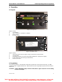 7
7
-
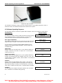 8
8
-
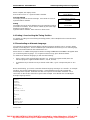 9
9
-
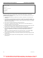 10
10
-
 11
11
-
 12
12
-
 13
13
-
 14
14
-
 15
15
-
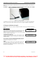 16
16
-
 17
17
-
 18
18
-
 19
19
-
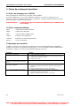 20
20
-
 21
21
-
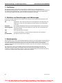 22
22
-
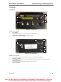 23
23
-
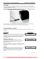 24
24
-
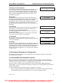 25
25
-
 26
26
-
 27
27
-
 28
28
-
 29
29
-
 30
30
-
 31
31
-
 32
32
-
 33
33
-
 34
34
-
 35
35
-
 36
36
-
 37
37
-
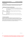 38
38
-
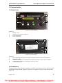 39
39
-
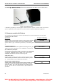 40
40
-
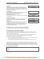 41
41
-
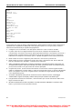 42
42
-
 43
43
-
 44
44
-
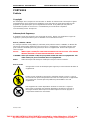 45
45
-
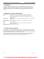 46
46
-
 47
47
-
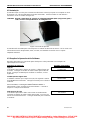 48
48
-
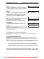 49
49
-
 50
50
-
 51
51
-
 52
52
-
 53
53
-
 54
54


Delphi YDT262 Operating And Servicing Manual
- Tipo
- Operating And Servicing Manual
En otros idiomas
- français: Delphi YDT262
- italiano: Delphi YDT262
- English: Delphi YDT262
- Deutsch: Delphi YDT262
- português: Delphi YDT262
Otros documentos
-
Haba 4638 El manual del propietario
-
DSE DSE7210 Manual de usuario
-
-
-
-
-
Aqara Hub Manual de usuario
-