Generac GP8000E 006931R0 Manual de usuario
- Categoría
- Generadores de poder
- Tipo
- Manual de usuario

Owner's Manual
GP 8000E Portable Generator
www.generac.com or 1-888-436-3722
DEADLY EXHAUST FUMES! ONLY use OUTSIDE far away
from windows, doors and vents!
NOT INTENDED FOR USE IN CRITICAL LIFE SUPPORT
APPLICATIONS.
SAVE this Manual. Provide this manual to any operator of
the generator.

Introduction ................................................................... 1
Read this Manual Thoroughly ..................................... 1
Safety Rules .................................................................. 1
Standards Index ................................................................... 3
General Information ..................................................... 4
1.1 Unpacking ............................................................................. 4
1.2 Assembly .............................................................................. 4
1.3 Emissions Information .......................................................... 5
Operation ....................................................................... 5
2.1 Know the Generator ............................................................. 5
2.2 Hour Meter ............................................................................ 6
2.3 Connection Plugs ................................................................. 6
2.4 How to Use the Generator.................................................... 7
2.5 Don’t Overload the Generator .............................................. 8
2.6 Wattage Reference Guide .................................................... 8
2.7 Before Starting the Generator .............................................. 9
2.8 Starting Pull Start Engines ................................................... 9
2.9 Starting Electric Start Engines ............................................ 10
2.10 Stooping the Engine ........................................................... 10
2.11 Low Oil Level Shutdown System .........................................11
2.12 Charging the Battery (Electric Start Units Only) ..................11
Maintenance ................................................................ 11
3.1 Performing Scheduled Maintenance ...................................11
3.2 Maintenance Schedule ........................................................11
3.3 Product Specifications .........................................................11
3.4 General Recommendations ................................................ 12
3.5 Service Air Filter ................................................................. 13
3.6 Valve Clearance ................................................................. 13
3.7 General ............................................................................... 13
3.8 Long Term Storage ............................................................. 14
3.9 Other Storage Tips ............................................................. 14
3.10 Spark Arrestor Service........................................................ 14
Troubleshooting ......................................................... 15
4.1 Troubleshooting Guide ....................................................... 15
4.2 Replacement Service Parts ................................................ 16
Notes ............................................................................ 17
Table of Contents
WARNING!
California Proposition 65
Engine exhaust and some of its constituents are known to the state of California to cause cancer,
birth defects, and other reproductive harm.
WARNING!
California Proposition 65
This product contains or emits chemicals known to the state of California to cause cancer,
birth defects, and other reproductive harm.

INTRODUCTION
Thank you for purchasing this model by Generac Power Systems, Inc.
This model is a compact, high performance, air-cooled, engine driven
generator designed to supply electrical power to operate electrical
loads where no utility power is available or in place of utility due to a
power outage.
READ THIS MANUAL THOROUGHLY
If any portion of this manual is not understood, contact the nearest
Authorized Dealer for starting, operating and servicing procedures.
The operator is responsible for proper and safe use of the equipment.
We strongly recommend that the operator read this manual and
thoroughly understand all instructions before using the equipment.
We also strongly recommend instructing other users to properly start
and operate the unit. This prepares them if they need to operate
the equipment in an emergency. Save these instructions for future
reference. If you loan this device to someone, ALWAYS loan these
instructions to the individual as well.
The generator can operate safely, efficiently and reliably only if it
is properly located, operated and maintained. Before operating or
servicing the generator:
• Become familiar with and strictly adhere to all local, state and
national codes and regulations.
• Study all safety warnings in this manual and on the product
carefully.
• Become familiar with this manual and the unit before use.
The manufacturer cannot anticipate every possible circumstance that
might involve a hazard. The warnings in this manual, and on tags and
decals affixed to the unit are, therefore, not all inclusive. If using a
procedure, work method or operating technique that the manufacturer
does not specifically recommend, ensure that it is safe for others.
Also make sure the procedure, work method or operating technique
utilized does not render the generator unsafe.
THE INFORMATION CONTAINED HEREIN WAS BASED ON
MACHINES IN PRODUCTION AT THE TIME OF PUBLICATION.
GENERAC RESERVES THE RIGHT TO MODIFY THIS MANUAL AT
ANY TIME.
SAFETY RULES
Throughout this publication, and on tags and decals affixed to the
generator, DANGER, WARNING, CAUTION and NOTE blocks are
used to alert personnel to special instructions about a particular
operation that may be hazardous if performed incorrectly or carelessly.
Observe them carefully. Their definitions are as follows:
INDICATES A HAZARDOUS SITUATION OR ACTION WHICH, IF
NOT AVOIDED, WILL RESULT IN DEATH OR SERIOUS INJURY.
Indicates a hazardous situation or action which, if not avoided,
could result in death or serious injury.
Indicates a hazardous situation or action which, if not
avoided, could result in minor or moderate injury.
NOTE:
Notes contain additional information important to a procedure
and will be found within the regular text body of this manual.
These safety warnings cannot eliminate the hazards that they
indicate. Common sense and strict compliance with the special
instructions while performing the action or service are essential to
preventing accidents.
Four commonly used safety symbols accompany the DANGER,
WARNING and CAUTION blocks. The type of information each
indicates is as follows:
This symbol points out important safety information that,
if not followed, could endanger personal safety and/or
property of others.
This symbol points out potential explosion hazard.
This symbol points out potential fire hazard.
This symbol points out potential electrical shock hazard.
Introduction
1

GENERAL HAZARDS
• NEVER operate in an enclosed area, in a vehicle, or indoors EVEN
IF doors and windows are open.
• For safety reasons, the manufacturer recommends that the
maintenance of this equipment is carried out by an Authorized
Dealer. Inspect the generator regularly, and contact the nearest
Authorized Dealer for parts needing repair or replacement.
• Operate generator only on level surfaces and where it will not be
exposed to excessive moisture, dirt, dust or corrosive vapors.
• Keep hands, feet, clothing, etc., away from drive belts, fans, and
other moving parts. Never remove any fan guard or shield while
the unit is operating.
• Certain parts of the generator get extremely hot during operation.
Keep clear of the generator until it has cooled to avoid severe
burns.
• Do NOT operate generator in the rain.
• Do not alter the construction of the generator or change controls
which might create an unsafe operating condition.
• Never start or stop the unit with electrical loads connected to
receptacles AND with connected devices turned ON. Start the
engine and let it stabilize before connecting electrical loads.
Disconnect all electrical loads before shutting down the generator.
• Do not insert objects through unit’s cooling slots.
• When working on this equipment, remain alert at all times. Never
work on the equipment when physically or mentally fatigued.
• Never use the generator or any of its parts as a step. Stepping on
the unit can stress and break parts, and may result in dangerous
operating conditions from leaking exhaust gases, fuel leakage, oil
leakage, etc.
EXHAUST & LOCATION HAZARDS
• Never operate in an enclosed area or indoors! NEVER use
in the home, in a vehicle, or in partly enclosed areas such
as garages, even if doors and windows are open! ONLY use
outdoors and far from open windows, doors, vents, and in an
area that will not accumulate deadly exhaust.
• The engine exhaust fumes contain carbon monoxide, which you
cannot see or smell. This poisonous gas, if breathed in sufficient
concentrations, can cause unconsciousness or even death.
• Adequate, unobstructed flow of cooling and ventilating air is critical
to correct generator operation. Do not alter the installation or
permit even partial blockage of ventilation provisions, as this can
seriously affect safe operation of the generator. The generator
MUST be operated outdoors.
• This exhaust system must be properly maintained. Do nothing that
might render the exhaust system unsafe or in noncompliance with
any local codes and/or standards.
• Always use a battery operated carbon monoxide alarm indoors,
installed according to the manufacturer's instructions.
• If you start to feel sick, dizzy, or weak after the generator has been
running, move to fresh air IMMEDIATELY. See a doctor, as you
could have carbon monoxide poisoning.
ELECTRICAL HAZARDS
• The generator produces dangerously high voltage when in
operation. Avoid contact with bare wires, terminals, connections,
etc., while the unit is running, even on equipment connected to the
generator. Ensure all appropriate covers, guards and barriers are
in place before operating the generator.
• Never handle any kind of electrical cord or device while
standing in water, while barefoot or while hands or feet are wet.
DANGEROUS ELECTRICAL SHOCK MAY RESULT.
• The National Electric Code (NEC) requires the frame and external
electrically conductive parts of the generator be properly connected
to an approved earth ground. Local electrical codes may also
require proper grounding of the generator. Consult with a local
electrician for grounding requirements in the area.
• Use a ground fault circuit interrupter in any damp or highly
conductive area (such as metal decking or steel work).
• Do not use worn, bare, frayed or otherwise damaged electrical
cord sets with the generator.
• Before performing any maintenance on the generator, disconnect
the engine starting battery (if equipped) to prevent accidental start
up. Disconnect the cable from the battery post indicated by a
NEGATIVE, NEG or (–) first. Reconnect that cable last.
• In case of accident caused by electric shock, immediately shut
down the source of electrical power. If this is not possible, attempt
to free the victim from the live conductor. AVOID DIRECT
CONTACT WITH THE VICTIM. Use a non-conducting
implement, such as a rope or board, to free the victim from the
live conductor. If the victim is unconscious, apply first aid and get
immediate medical help.
Safety Rules
2

FIRE HAZARDS
• Gasoline is highly FLAMMABLE and its vapors are EXPLOSIVE.
Never permit smoking, open flames, sparks or heat in the
vicinity while handling gasoline.
• Never add fuel while unit is running or hot. Allow engine to cool
completely before adding fuel.
• Never fill fuel tank indoors. Comply with all laws regulating
storage and handling of gasoline.
• Do not overfill the fuel tank. Always allow room for fuel
expansion. If tank is over-filled, fuel can overflow onto a hot
engine and cause FIRE or an EXPLOSION. Never store generator
with fuel in tank where gasoline vapors might reach an open flame,
spark or pilot light (as on a furnace, water heater or clothes dryer).
FIRE or EXPLOSION may result. Allow unit to cool entirely before
storage.
• Wipe up any fuel or oil spills immediately. Ensure that no
combustible materials are left on or near the generator. Keep the
area surrounding the generator clean and free from debris and
keep a clearance of five (5) feet on all side to allow for proper
ventilation of the generator.
• Do not insert objects through unit’s cooling slots.
• Never operate the generator if connected electrical devices
overheat, if electrical output is lost, if engine or generator sparks or
if flames or smoke are observed while unit is running.
• Keep a fire extinguisher near the generator at all times.
STANDARDS INDEX
1. National Fire Protection Association (NFPA) 70: The NATIONAL
ELECTRIC CODE (NEC) available from www.nfpa.org
2. National Fire Protection Association (NFPA) 5000: BUILDING
CONSTRUCTION AND SAFETY CODE available from www.
nfpa.org
3. International Building Code available from www.iccsafe.org
4. Agricultural Wiring Handbook available from www.rerc.org ,
Rural Electricity Resource Council P.O. Box 309 Wilmington, OH
45177-0309
5. ASAE EP-364.2 Installation and Maintenance of Farm Standby
Electric Power available from www.asabe.org, American Society
of Agricultural & Biological Engineers 2950 Niles Road, St.
Joseph, MI 49085
This list is not all inclusive. Check with the Authority Having Local
Jurisdiction (AHJ) for any local codes or standards which may be
applicable to your jurisdiction.
MODEL NO:
SERIAL NO:
Unit ID Location
MODEL
DATA
DECAL
Safety Rules
3

4
1.1 UNPACKING
• Remove all packaging material.
• Remove separate accessory box.
• Remove the generator from carton.
1.1.1 ACCESSORIES
Check all contents. If any parts are missing or damaged, locate an
authorized dealer at 1-888-436-3722.
• 1 - Owner’s Manual • 1 - Handle Assembly
• 1 - Liter Oil SAE 30 • 2 - Frame Foot
• 2 - Never-Flat Wheels • 1 - 20' Power Cord
• 3 - Product Registration Cards
• 1 - Service Warranty • 1 - Emissions Warranty
• 1 - Battery Charger (Electric Start Models)
• 1 - Hardware Bag (containing the following):
– 2-Rubber Feet – 6-M8 Bolt (Long)
– 2-1/2” Axle Pins
– 2-M6 Bolts (Long)
– 2-Cotter Pins
– 2-M8 Acorn Nut
– 2-1/2” Flat Washers
– 4-Hex Flanged M8 Nuts
– 2-Hex Flanged M6 Nuts
1.2 ASSEMBLY
The generator requires some assembly prior to using it. If problems
arise when assembling the generator, please call the Generator
Helpline at 1-888-436-3722.
1.2.1 ASSEMBLING THE ACCESSORY KIT
The wheels are designed into the unit to greatly improve the portability
of the generator.
You will need the following tools to properly install the accessory kit.
• Needle Nose Pliers
• Ratchet and 8mm, 10mm, and 13mm sockets
• 8mm, 10mm, and 13mm box wrenches
NOTE:
The wheels are not intended for over-the-road use.
1. Refer to Figure 1 and install the Wheels as follows:
– Slide the Axle Pin through the Wheel, 1/2" Flat Washer, and Wheel
Bracket on the frame.
– Insert the Cotter Pin through the Axle Pin then bend the tabs (of the
Cotter Pins) outward to lock into place.
2. Refer to Figure 1 and install the Frame Foot and Rubber
Bumpers as shown.
– Slide the Rubber Bumper studs through the Frame Foot then install
the Locking Flange Nuts.
– Slide the Hex Head Bolts through the holes in the Frame Rail.
– Slide the Frame Foot onto the Hex Head Bolts then install the Locking
Flange Nuts.
3. Refer to Figure 1 and install the Handle as shown.
– Slide the long Bolts through the Handle Bracket and Handle, then
install the Hex Nuts.
Figure 1 – Wheel & Handle Assembly
2 X RUBBER FOOT
2 X M6 BOLT
(LONG)
2 X M6 NUTS
4 X M8 NUTS
2 X FRAME FOOT
2 X AXLE PIN
2 X WHEEL
2 X 1/2” FLAT WASHER
2 X COTTER PIN
4 X M8 BOLT
(LONG)
2 X M8 BOLT (LONG)
2 X M8 ACORN NUT
HANDLE
ASSEMBLY
1.2.2 BATTERY CABLE CONNECTION
The unit has been deliberately shipped with the battery cables
disconnected.
To connect the battery, you will need two 8mm box wrenches to
connect the battery cables. (see Figure 16 for connection details):
1. Cut off cable ties securing battery cables and remove red covers
from battery terminals.
2. First, connect the red cable to the positive (+) battery terminal
with the bolt and nut supplied.
3. Make sure connections are secure and slide rubber boot over the
positive (+) battery terminal and connection hardware.
4. Connect the black cable to the negative (-) battery terminal with
the bolt and nut supplied and slide rubber boot over the negative
(-) battery terminal and connection hardware.
5. Make sure all connections are secure.
NOTE:
If the battery is unable to start the engine, charge it with the
12V charger included in the accessory box (see the "Charging a
Battery" section for details).
General Information

5
1.3 EMISSIONS INFORMATION
The Environmental Protection Agency and California Air Resource
Board for generators certified to CA standards requires that this
generator comply with exhaust and evaporative emission standards.
Locate the emissions compliance decal on the engine to determine
what standards the generator meets, and to determine which
warranty applies. This generator is certified to operate on gasoline.
The emission control system includes the following components (if
equipped):
• Air Induction System
– Intake Pipe / Manifold
– Air Cleaner
• Fuel System
– Carburetor
– Fuel Tank / Cap
– Fuel Lines
– Evaporative Vent Lines
– Carbon Canister
• Ignition System
– Spark Plug
– Ignition Module
• Exhaust System
– Exhaust Manifold
– Muffler
– Pulsed Air Valve
– Catalyst
2.1 KNOW THE GENERATOR
Read the Owner’s Manual and Safety Rules before operating this
generator.
Compare the generator to Figures 2 through 4 to become familiarized
with the locations of various controls and adjustments. Save this
manual for future reference.
1. 120 Volt AC, 20 Amp GFCI Duplex Outlets – Supplies electrical
power for the operation of 120 Volt AC, 20 Amp, single-phase,
60 Hz, electrical lighting, appliance, tool and motor loads. It
also provides protection with an integral Ground Fault Circuit
Interrupter, complete with a press to TEST and RESET button.
2. 120/240 Volt AC, 30 Amp Locking Receptacle – Supplies
electrical power for the operation of 120 and/or 240 Volt AC, 30
Amp, single-phase, 60 Hz, electrical lighting, appliance, tool and
motor loads.
3. Circuit Breakers (AC) – Each receptacle is provided with a
push-to-reset circuit breaker to protect the generator against
electrical overload.
4. Oil Drain – Use to drain engine oil.
5. Air Filter – Filters intake air as it is drawn into the engine.
6. Choke Knob – Used when starting a cold engine.
7. Fuel Tank – See generator Specifications for tank capacity.
8. Grounding Lug – Ground the generator to an approved earth
ground here. See "Grounding the Generator" for details.
9. Start Switch – Used to start engine from the starter motor
(electric start models only).
10. Muffler – Quiets the engine.
11. Handle – Pivot and retract for storage. Press the spring-loaded
button to move handles.
12. Gas Cap – Fuel fill location.
13. Fuel Gauge – Shows fuel level in tank.
14. Oil Fill – Add oil here.
15. Recoil Starter – Use to start engine manually.
16. Fuel Shut Off – Valve between fuel tank and carburetor.
17. Roll Over Valve – Passes fuel to the engine airbox.
18. Recovery Hose – Install between the carbon canister and the
roll over valve (if equipped).
19. Hour Meter – Tracks hours of operation.
20. Battery Charger Input – This receptacle allows the capability
to recharge the 12 volt DC storage battery provided with the 12
Volt Adaptor Plug Charger which is included in the Accessory
Box. Located behind the battery charger input is a 1.50 Amp
in-line fuse which is inside the control panel to protect the battery
(electric start models only).
21. Battery – Powers the electric starter (electric start models only).
Figure 2 - Control Panel
20
9
19
2
3
1
Figure 3 - Generator Controls
17
18
6
5
11
15
16
Operation

6
Figure 4 - Generator Controls
2.2 HOUR METER
The hour meter tracks hours of operation for scheduled maintenance
(Figure 5):
There will be a "CHG OIL" message every 100 hours. The message
will flash one hour before and one hour after each 100 hour interval,
providing a two hour window to perform service.
This message will actually begin flashing at 99 hours and disable
itself at 101 hours again, providing a two hour window to perform the
service.
Every 200 hours the "SVC" icon on the lower left hand corner of the
display will flash. The message will flash one hour before and one
hour after each 200 hour interval providing a two hour window to
perform service.
Figure 5 – Hour Meter
HOUR GLASS
GRAPHIC
RESET BUTTON
(IF EQUIPPED)
0000.0
When the hour meter is in the Flash Alert mode, the maintenance
message will always alternate with elapsed time in hours and tenths.
The hours will flash four times, then alternate with the maintenance
message four times until the meter resets itself.
• 100 hours - CHG OIL — Oil Change Interval (Every 100 hrs)
• 200 hours - SVC — Service Air Filter (Every 200 hrs)
NOTE:
The hour glass graphic will flash on and off when the engine
is running. This signifies that the meter is tracking hours of
operation.
2.3 CONNECTION PLUGS
2.3.1 120 VAC, 20 AMP, GFCI DUPLEX RECEPTACLE
This is a 120 Volt outlet protected against overload by a 20 Amp
push-to-reset circuit breaker (Figure 6). Use each socket to power
120 Volt AC, single phase, 60 Hz electrical loads requiring up to a
combined 2400 watts (2.4 kW) or 20 Amps of current. Use only high
quality, well-insulated, 3-wire grounded cord sets rated for 125 Volts
at 20 Amps (or greater).
Keep extension cords as short as possible to prevent voltage drop
and possible overheating of wires.
Figure 6 - 120 Volt AC, 20 Amp, GFCI Duplex Receptacle
2.3.2 120/240 VAC, 30 AMP RECEPTACLE
Use a NEMA L14-30 plug with this receptacle (rotate to lock/unlock).
Connect a suitable 4-wire grounded cord set to the plug and to the
desired load. The cord set should be rated for 250 Volts AC at 30
Amps (or greater) (Figure 7).
Use this receptacle to operate 120 Volt AC, 60 Hz, single phase loads
requiring up to 3600 watts (3.6 kW) of power at 30 Amps or 240 Volt
AC, 60 Hz, single phase loads requiring up to 7200 watts (7.2 kW)
of power at 30 Amps. The outlet is protected by two 25 Amp (5.5kW)
or two 30 Amp (6.5kW) push-to-reset or one 30 Amp 2-pole toggle
switch or two 30 Amp push button to reset (6.5/7.5kW) circuit breaker.
Operation

7
Figure 7 - 120/240 VAC, 30 Amp Receptacle
2.4 HOW TO USE THE GENERATOR
See the "To Start the Engine" section for how to safely start and stop
the generator and how to connect and disconnect loads. If there
are any problems operating the generator, please call the generator
helpline at 1-888-436-3722.
Never operate in an enclosed area or indoors! NEVER
use in the home, in a vehicle, or in partly enclosed areas
such as garages, EVEN IF doors and windows are open!
ONLY use outdoors and far from open windows, doors,
vents, and in an area that will not accumulate deadly
exhaust.
The engine exhaust fumes contain carbon monoxide,
which you cannot see or smell. This poisonous gas,
if breathed in sufficient concentrations, can cause
unconsciousness or even death.
Adequate, unobstructed flow of cooling and ventilating
air is critical to correct generator operation. Do not
alter the installation or permit even partial blockage of
ventilation provisions, as this can seriously affect safe
operation of the generator. The generator MUST be
operated outdoors.
This exhaust system must be properly maintained. Do
nothing that might render the exhaust system unsafe or
in noncompliance with any local codes and/or standards.
Always use a battery operated carbon monoxide alarm
indoors, installed according to the manufacturer's
instructions.
2.4.1 GROUNDING THE GENERATOR WHEN USED AS A
PORTABLE
This generator has an equipment ground that connects the generator
frame components to the ground terminals on the AC output
receptacles (see NEC 250.34 (A) for explanation). This allows the
generator to be used as a portable without grounding the frame of the
generator as specified in NEC 250.34.
2.4.2 SPECIAL REQUIREMENTS
There may be Federal or State Occupational Safety and Health
Administration (OSHA) regulations, local codes, or ordinances that
apply to the intended use of the generator.
Please consult a qualified electrician, electrical inspector, or the local
agency having jurisdiction:
• In some areas, generators are required to be registered with local
utility companies.
• If the generator is used at a construction site, there may be
additional regulations which must be observed.
Operation

8
2.4.3 CONNECTING THE GENERATOR TO A BUILDING’S
ELECTRICAL SYSTEM
When connecting directly to a building's electrical system, it is recommended
that a manual transfer switch is used. Connections for a portable generator to
a building's electrical system must be made by a qualified electrician and in
strict compliance with all national and local electrical codes and laws.
Figure 8 - Grounding the Generator
2.5 DON’T OVERLOAD THE GENERATOR
Overloading a generator in excess of its rated wattage capacity can
result in damage to the generator and to connected electrical devices.
Observe the following to prevent overloading the unit:
• Add up the total wattage of all electrical devices to be connected
at one time. This total should NOT be greater than the generator's
wattage capacity.
• The rated wattage of lights can be taken from light bulbs. The rated
wattage of tools, appliances and motors can usually be found on
a data label or decal affixed to the device.
• If the appliance, tool or motor does not give wattage, multiply volts
times ampere rating to determine watts (volts x amps = watts).
• Some electric motors, such as induction types, require about three
times more watts of power for starting than for running. This surge
of power lasts only a few seconds when starting such motors.
Make sure to allow for high starting wattage when selecting
electrical devices to connect to the generator:
1. Figure the watts needed to start the largest motor.
2. Add to that figure the running watts of all other connected loads.
The Wattage Reference Guide is provided to assist in determining
how many items the generator can operate at one time.
NOTE:
All figures are approximate. See data label on appliance for
wattage requirements.
2.6 WATTAGE REFERENCE GUIDE
Device . . . . . . . . . . . . . . . . . . . . . . . . . . . . . Running Watts
*Air Conditioner (12,000 Btu) . . . . . . . . . . . . . . . . . . . . . . . . . . . . . . 1700
*Air Conditioner (24,000 Btu) . . . . . . . . . . . . . . . . . . . . . . . . . . . . . . 3800
*Air Conditioner (40,000 Btu) . . . . . . . . . . . . . . . . . . . . . . . . . . . . . . 6000
Battery Charger (20 Amp). . . . . . . . . . . . . . . . . . . . . . . . . . . . . . . . . . 500
Belt Sander (3") . . . . . . . . . . . . . . . . . . . . . . . . . . . . . . . . . . . . . . . . 1000
Chain Saw. . . . . . . . . . . . . . . . . . . . . . . . . . . . . . . . . . . . . . . . . . . . . 1200
Circular Saw (6-1/2"). . . . . . . . . . . . . . . . . . . . . . . . . . . . . . . .800 to 1000
*Clothes Dryer (Electric) . . . . . . . . . . . . . . . . . . . . . . . . . . . . . . . . . 5750
*Clothes Dryer (Gas). . . . . . . . . . . . . . . . . . . . . . . . . . . . . . . . . . . . . . 700
*Clothes Washer . . . . . . . . . . . . . . . . . . . . . . . . . . . . . . . . . . . . . . . . 1150
Coffee Maker. . . . . . . . . . . . . . . . . . . . . . . . . . . . . . . . . . . . . . . . . . . 1750
*Compressor (1 HP) . . . . . . . . . . . . . . . . . . . . . . . . . . . . . . . . . . . . . 2000
*Compressor (3/4 HP). . . . . . . . . . . . . . . . . . . . . . . . . . . . . . . . . . . . 1800
*Compressor (1/2 HP). . . . . . . . . . . . . . . . . . . . . . . . . . . . . . . . . . . . 1400
Curling Iron . . . . . . . . . . . . . . . . . . . . . . . . . . . . . . . . . . . . . . . . . . . . . 700
*Dehumidifier. . . . . . . . . . . . . . . . . . . . . . . . . . . . . . . . . . . . . . . . . . . . 650
Disc Sander (9") . . . . . . . . . . . . . . . . . . . . . . . . . . . . . . . . . . . . . . . . 1200
Edge Trimmer . . . . . . . . . . . . . . . . . . . . . . . . . . . . . . . . . . . . . . . . . . . 500
Electric Blanket . . . . . . . . . . . . . . . . . . . . . . . . . . . . . . . . . . . . . . . . . . 400
Electric Nail Gun . . . . . . . . . . . . . . . . . . . . . . . . . . . . . . . . . . . . . . . . 1200
Electric Range (per element) . . . . . . . . . . . . . . . . . . . . . . . . . . . . . . 1500
Electric Skillet . . . . . . . . . . . . . . . . . . . . . . . . . . . . . . . . . . . . . . . . . . 1250
*Freezer . . . . . . . . . . . . . . . . . . . . . . . . . . . . . . . . . . . . . . . . . . . . . . ..700
*Furnace Fan (3/5 HP) . . . . . . . . . . . . . . . . . . . . . . . . . . . . . . . . . . . . 875
*Garage Door Opener. . . . . . . . . . . . . . . . . . . . . . . . . . . . . . . .500 to 750
Hair Dryer . . . . . . . . . . . . . . . . . . . . . . . . . . . . . . . . . . . . . . . . . . . . . 1200
Hand Drill . . . . . . . . . . . . . . . . . . . . . . . . . . . . . . . . . . . . . . . .250 to 1100
Hedge Trimmer . . . . . . . . . . . . . . . . . . . . . . . . . . . . . . . . . . . . . . . . . . 450
Impact Wrench . . . . . . . . . . . . . . . . . . . . . . . . . . . . . . . . . . . . . . . . . . 500
Iron . . . . . . . . . . . . . . . . . . . . . . . . . . . . . . . . . . . . . . . . . . . . . . . . . . 1200
*Jet Pump . . . . . . . . . . . . . . . . . . . . . . . . . . . . . . . . . . . . . . . . . . . . . . 800
Lawn Mower . . . . . . . . . . . . . . . . . . . . . . . . . . . . . . . . . . . . . . . . . . . 1200
Light Bulb . . . . . . . . . . . . . . . . . . . . . . . . . . . . . . . . . . . . . . . . . . . . . . 100
Microwave Oven . . . . . . . . . . . . . . . . . . . . . . . . . . . . . . . . . . .700 to 1000
*Milk Cooler. . . . . . . . . . . . . . . . . . . . . . . . . . . . . . . . . . . . . . . . . . . . 1100
Oil Burner on Furnace . . . . . . . . . . . . . . . . . . . . . . . . . . . . . . . . . . . . 300
Oil Fired Space Heater (140,000 Btu) . . . . . . . . . . . . . . . . . . . . . . . . 400
Oil Fired Space Heater (85,000 Btu) . . . . . . . . . . . . . . . . . . . . . . . . . 225
Oil Fired Space Heater (30,000 Btu) . . . . . . . . . . . . . . . . . . . . . . . . . 150
*Paint Sprayer, Airless (1/3 HP) . . . . . . . . . . . . . . . . . . . . . . . . . . . . . 600
Paint Sprayer, Airless (handheld) . . . . . . . . . . . . . . . . . . . . . . . . . . . . 150
Radio. . . . . . . . . . . . . . . . . . . . . . . . . . . . . . . . . . . . . . . . . . . . . .50 to 200
*Refrigerator . . . . . . . . . . . . . . . . . . . . . . . . . . . . . . . . . . . . . . . . . . . . 700
Slow Cooker . . . . . . . . . . . . . . . . . . . . . . . . . . . . . . . . . . . . . . . . . . . . 200
*Submersible Pump (1-1/2 HP) . . . . . . . . . . . . . . . . . . . . . . . . . . . . 2800
*Submersible Pump (1 HP). . . . . . . . . . . . . . . . . . . . . . . . . . . . . . . . 2000
*Submersible Pump (1/2 HP) . . . . . . . . . . . . . . . . . . . . . . . . . . . . . . 1500
*Sump Pump. . . . . . . . . . . . . . . . . . . . . . . . . . . . . . . . . . . . . .800 to 1050
*Table Saw (10") . . . . . . . . . . . . . . . . . . . . . . . . . . . . . . . . . .1750 to 2000
Television . . . . . . . . . . . . . . . . . . . . . . . . . . . . . . . . . . . . . . . . .200 to 500
Toaster . . . . . . . . . . . . . . . . . . . . . . . . . . . . . . . . . . . . . . . . .1000 to 1650
Weed Trimmer. . . . . . . . . . . . . . . . . . . . . . . . . . . . . . . . . . . . . . . . . . . 500
* Allow 3 times the listed watts for starting these devices.
Operation

9
2.7 BEFORE STARTING THE GENERATOR
Prior to operating the generator, engine oil and gasoline will need to
be added, as follows:
2.7.1 ADDING ENGINE OIL
All oil should meet minimum American Petroleum Institute (API)
Service Class SJ, SL or better. Use no special additives. Select the
oil's viscosity grade according to the expected operating temperature
(also see chart).
• Above 40° F, use SAE 30
• Below 40° F and down to 10° F, use 10W-30
• All temperatures, use synthetic 5W-30
SAE 30
10W-30
Synt h e t i c 5W-30
Any attempt to crank or start the engine before it has
been properly serviced with the recommended oil may
result in an engine failure.
1. Place generator on a level surface (not to exceed 15° in any
direction).
2. Clean area around oil fill and remove oil fill cap and dipstick.
3. Wipe dipstick clean.
4. Slowly fill engine with oil through the oil fill opening until it
reaches the full mark. Stop filling occasionally to check oil level.
Be careful not to over fill.
5. Install oil fill cap and finger tighten securely.
6. Check engine oil level before starting each time thereafter.
2.7.2 ADDING GASOLINE
Never fill fuel tank indoors. Never fill fuel tank when
engine is running or hot. Avoid spilling gasoline on a hot
engine. Allow engine to cool entirely before filling fuel
tank. DO NOT light a cigarette or smoke when filling the
fuel tank.
Do not overfill the fuel tank. Always leave room for fuel
expansion. If the fuel tank is overfilled, fuel can overflow
onto a hot engine and cause FIRE or EXPLOSION. Wipe
up any spilled fuel immediately.
Never light a cigarette or smoke when filling the fuel
tank. Gasoline is highly FLAMMABLE and its vapors are
EXPLOSIVE. Never permit smoking, open flames, sparks
or heat in the vicinity while handling gasoline.
1. Use regular UNLEADED gasoline with the generator engine. Do
not use any gasoline with more than 10% added ethanol. Do not
use E85 gasoline. Do not mix oil with gasoline.
2. Clean area around fuel fill cap, remove cap.
3. Slowly add unleaded regular gasoline to fuel tank. Be careful
not to overfill (Figure 9).
4. Install fuel cap and wipe up any spilled gasoline.
Figure 9 - Fuel Tank
DO NOT Fill Above Lip
Fuel
Fuel Tank
IMPORTANT: It is important to prevent gum deposits from forming
in fuel system parts such as the carburetor, fuel hose or tank during
storage. Alcohol-blended fuels (called gasohol, ethanol or methanol)
can attract moisture, which leads to separation and formation of acids
during storage. Acidic gas can damage the fuel system of an engine
while in storage. To avoid engine problems, the fuel system should
be emptied before storage of 30 days or longer. See the "Storage"
section. Never use engine or carburetor cleaner products in the fuel
tank as permanent damage may occur.
2.8 STARTING PULL START ENGINES
Never start or stop engine with electrical devices plugged
into the receptacles AND devices turned on.
1. Unplug all electrical loads from the unit's receptacles before
starting the engine.
2. Make sure the unit is in a level position (not to exceed 15° in any
direction).
3. OPEN the Fuel Shut-off Valve (Figure 10).
4. Turn engine RUN/STOP switch to ON position.
5. Slide engine choke to the LEFT to FULL CHOKE position (Figure
11).
6. To start engine, firmly grasp the recoil handle and pull slowly until
increased resistance is felt. Pull rapidly up and away.
7. When engine starts, move choke knob to 1/2-CHOKE position
until engine runs smoothly and then fully into RUN position. If
engine falters, move choke back out to 1/2-CHOKE position until
engine runs smoothly and then to RUN position.
Operation

10
NOTE:
If engine fires, but does not continue to run, move choke lever to
FULL CHOKE and repeat starting instructions.
IMPORTANT: Do not overload the generator. Also, do not overload
individual panel receptacles. These outlets are protected against
overload with push-to-reset-type circuit breakers. If amperage rating
of any circuit breaker is exceeded, that breaker opens and electrical
output to that receptacle is lost. Read “Don’t Overload the Generator”
carefully.
Figure 10 - Fuel Shut-off Valve
Figure 11 - Choke Position
CHOKE LEVER
LEFT = CHOKE (START)
RIGHT = RUN
2.9 STARTING ELECTRIC START ENGINES
Never start or stop engine with electrical devices plugged
into the receptacles AND devices turned on.
1. Unplug all electrical loads from the unit's receptacles before
starting the engine.
2. Make sure the unit is in a level position (not to exceed 15° in any
direction).
3. Open the fuel shut-off valve (Figures 10).
4. Move engine CHOKE knob outward to FULL CHOKE position
(Figure 12).
5. To start engine, press and hold the Start/Run/Stop switch in the
“Start” position. The engine will crank and attempt to start. When
the engine starts, release the switch to the run position.
6. When the engine starts, move choke knob to “1/2 Choke”
position until the engine runs smoothly and then fully in to the
“Run” position. If engine falters, move choke knob back out to
“1/2 Choke” position until the engine runs smoothly and then to
“Run” position.
2.9.1 MANUAL START
This generator is also equipped with a manual recoil starter which
may be used if the battery is discharged.
NOTE:
The switch must be in the RUN position. Use one of the
generator’s receptacle outlets along with the included battery
charger to charge the battery while the generator is running.
• To start manually, firmly grasp the recoil handle and pull slowly
until increased resistance is felt. Pull rapidly up and away to start
engine. Then follow the same choke sequence.
NOTE:
If engine fires, but does not continue to run, move choke lever to
FULL CHOKE and repeat starting instructions.
IMPORTANT: Do not overload the generator. Also, do not overload
individual panel receptacles. These outlets are protected against
overload with push-to-reset-type circuit breakers. If amperage rating
of any circuit breaker is exceeded, that breaker opens and electrical
output to that receptacle is lost. Read “Don’t Overload the Generator”
carefully.
2.10 STOPPING THE ENGINE
1. Shut off all loads, then unplug the electrical loads from generator
panel receptacles. Never start or stop the engine with electrical
devices plugged in and turned on.
2. Let engine run at no-load for several minutes to stabilize the
internal temperatures of engine and generator.
3. Move Run/Stop switch to OFF position.
4. Close fuel valve.
Operation

11
2.11 LOW OIL LEVEL SHUTDOWN SYSTEM
The engine is equipped with a low oil level sensor that shuts down
the engine automatically when the oil level drops below a specified
level. If the engine shuts down by itself and the fuel tank has enough
gasoline, check engine oil level.
2.11.1 SENSING LOW OIL LEVEL
If the system senses a low oil level during operation, the engine shuts
down. The engine will not run until the oil has been refilled to the
proper level.
2.12 CHARGING THE BATTERY (ELECTRIC
START UNITS ONLY)
Storage batteries give off explosive hydrogen gas while
recharging. An explosive mixture will remain around the
battery for a long time after it has been charged. The
slightest spark can ignite the hydrogen and cause an
explosion. Such an explosion can shatter the battery and
cause blindness or other serious injury.
Do not permit smoking, open flame, sparks or any other
source of heat around a battery. Wear protective goggles,
rubber apron and rubber gloves when working around a
battery. Battery electrolyte fluid is an extremely corrosive
sulfuric acid solution that can cause severe burns. If spill
occurs flush area with clear water immediately.
NOTE:
The battery shipped with the generator has been fully charged.
A battery may lose some of its charge when not in use for
prolonged periods of time. If the battery is unable to crank the
engine, plug in the 12V charger included in the accessory box.
RUNNING THE GENERATOR DOES NOT CHARGE THE BATTERY.
Use battery charger plug to keep the battery charged and ready for
use. Battery charging should be done in a dry location.
1. Plug charger into “Battery Charger Input” jack, located on the
control panel (Figure 12). Plug wall receptacle end of the battery
charger into a 120 Volt AC wall outlet.
2. Unplug battery charger from wall outlet and control panel jack
when generator is going to be in use.
NOTE:
Charge the battery at least once every three (3) months. Do not
use the battery charger for more than 48 hours at one charge.
Charger input is protected by a 1.5 Amp replaceable in-line fuse.
Figure 12 - Battery Charger Jack
BATTERY
CHARGER
INPUT
3.1 PERFORMING SCHEDULED MAINTENANCE
It is important to perform service as specified in the Maintenance
Schedule for proper generator operation, and to ensure that the
generator complies with the applicable emission standards for the
duration of its useful life. Service and repairs may be performed by
any capable person or repair shop. Additionally, emissions critical
maintenance must be performed as scheduled in order for the
Emissions Warranty to be valid. Emissions critical maintenance
consists of servicing the air filter and spark plugs in accordance with
the Maintenance Schedule.
3.2 MAINTENANCE SCHEDULE
Follow the calendar intervals. More frequent service is required when
operating in adverse conditions noted below.
Check Oil Level At Each Use
Change Oil ‡ *Every 100 hours or Every Season
Check Valve Clearance ***Every Season
Service Air Filter ** Every 200 hours or Every Season
Replace Spark Plug Every Season
‡ Change oil after first 30 hours of operation then every season.
* Change oil and oil filter every month when operating under heavy load or in high
temperatures.
** Clean more often under dirty or dusty operating conditions. Replace air filter parts
if they cannot be adequately cleaned.
*** Check valve clearance and adjust if necessary after first 50 hours of operation and
every 100 hours thereafter.
3.3 PRODUCT SPECIFICATIONS
3.3.1 GENERATOR SPECIFICATIONS
Rated Power ..................................................................................... 8.0 kW**
Surge Power ......................................................................................... 10 kW
Rated AC Voltage .............................................................................. 120/240
Rated AC Load
Current @ 240V ....................................................................... 33.3 Amps**
Current @ 120V ....................................................................... 66.6 Amps**
Rated Frequency ............................................................ 60 Hz @ 3600 RPM
Phase ........................................................................................ Single Phase
Unit Weight .............................................................................. 86.9kg (191.5)
Unit Dimensions ............................L = 692mm (27.25") x W = 687mm (27") x
H = 638mm (25")
** Operating Temperature Range : -18 deg. C (0 deg. F) to 40 Deg. C (104 Deg. F).
When operated above 25 deg. C (77 deg. F) there may be a decrease in power.
** Maximum wattage and current are subject to, and limited by, such factors as fuel
Btu content, ambient temperature, altitude, engine condition, etc.. Maximum power
decreases about 3.5% for each 1,000 feet above sea level; and will also decrease
about 1% for each 6° C (10° F) above 16° C (60° F) ambient temperature.
Maintenance

12
Maintenance
3.3.2 ENGINE SPECIFICATIONS
Displacement .........................................................................................420cc
Spark Plug Type .................................... Champion N9YC or NHSP LDF7TC
Spark Plug Part No. ...................................................................0G84420101
Spark Plug Gap ..................................... 0.028-0.031 inch or (0.70-0.80 mm)
Gasoline Capacity ................................................... 28.4 L (7.5 U.S. gallons)
Oil Type ......................See Chart in "Before Starting the Generator" Section
Oil Capacity ................................................................... 1.0 Liters (1.06 Qts.)
Run Time (50% Load) ......................................................................11 Hours
Battery ........................................................................ 12 VDC, 10 Amp Hour
3.4 GENERAL RECOMMENDATIONS
The warranty of the generator does not cover items that have been
subjected to operator abuse or negligence. To receive full value from
the warranty, the operator must maintain the generator as instructed
in this manual.
Some adjustments will need to be made periodically to properly
maintain the generator.
All adjustments in the Maintenance section of this manual should
be made at least once each season. Follow the requirements in the
"Maintenance Schedule".
NOTE:
Once a year replace the spark plug and replace the air filter. A
new spark plug and clean air filter assure proper fuel-air mixture
and help the engine run better and last longer.
3.4.1 GENERATOR MAINTENANCE
Generator maintenance consists of keeping the unit clean and dry.
Operate and store the unit in a clean dry environment where it will not
be exposed to excessive dust, dirt, moisture or any corrosive vapors.
Cooling air slots in the generator must not become clogged with snow,
leaves, or any other foreign material.
Check the cleanliness of the generator frequently and clean when
dust, dirt, oil, moisture or other foreign substances are visible on its
exterior surface.
Never insert any object or tool through the air cooling
slots, even if the engine is not running.
NOTE:
DO NOT use a garden hose to clean generator. Water can enter
the engine fuel system and cause problems. In addition, if water
enters the generator through cooling air slots, some water will
be retained in voids and crevices of the rotor and stator winding
insulation. Water and dirt buildup on the generator internal
windings will eventually decrease the insulation resistance of
these windings.
3.4.2 TO CLEAN THE GENERATOR
• Use a damp cloth to wipe exterior surfaces clean.
• A soft, bristle brush may be used to loosen caked on dirt, oil, etc.
• A vacuum cleaner may be used to pick up loose dirt and debris.
• Low pressure air (not to exceed 25 psi) may be used to blow away
dirt. Inspect cooling air slots and openings on the generator. These
openings must be kept clean and unobstructed.
3.4.3 ENGINE MAINTENANCE
When working on the generator, always disconnect spark
plug wire from spark plug and keep wire away from spark
plug.
3.4.4 CHECKING OIL LEVEL
See the “Before Starting the Generator” section for information on
checking the oil level. The oil level should be checked before each
use, or at least every eight hours of operation. Keep the oil level
maintained.
3.4.5 CHANGING THE OIL
Change the oil after every 100 hours. If running this unit under dirty
or dusty conditions, or in extremely hot weather, change the oil more
often.
Hot oil may cause burns. Allow engine to cool before
draining oil. Avoid prolonged or repeated skin exposure
with used oil. Thoroughly wash exposed areas with soap.
Use the following instructions to change the oil after the engine
cools down:
1. Clean area around oil drain plug.
2. Remove oil drain plug from engine and oil fill plug to drain oil
completely into a suitable container.
3. When oil has completely drained, install oil drain plug and tighten
securely.
4. Fill engine with recommended oil. (See “Before Starting the
Generator” for oil recommendations).
5. Wipe up any spilled oil.
6. Dispose of used oil at a proper collection center.
3.4.6 REPLACING THE SPARK PLUG
Use Champion N9YC spark plug or equivalent. Replace the plug
every 200 hours. This will help the engine start easier and run better.
1. Stop the engine and pull the spark plug wire off of the spark plug.
2. Clean the area around the spark plug and remove it from the
cylinder head.
3. Set the spark plug's gap to 0.70-0.80 mm (0.028-0.031 in.). Install
the correctly gapped spark plug into the cylinder head (Figure
13).
Figure 13 - Spark Plug Gap

13
Maintenance
3.4.7 BATTERY REPLACEMENT
NOTE:
The battery shipped with the generator has been fully charged.
A battery may lose some of its charge when not in use for
prolonged periods of time. If the battery is unable to crank the
engine, plug in the 12V charger included in the accessory box
(see the Charging a Battery section). RUNNING THE GENERATOR
DOES NOT CHARGE THE BATTERY. The part number for this
battery is 0G9449.
The NEGATIVE battery terminal should:
1. Always be DISCONNECTED FIRST.
2. Always be CONNECTED LAST.
Figure 14 - Battery Connections
RED (+)
BLACK (-)
3.5 SERVICE AIR FILTER
The engine will not run properly and may be damaged if using a dirty
air filter. Clean the air filter every 200 hours or once a year (Figure 15).
Clean or replace more often if operating under dusty conditions. The
air filter part number is 0G84420151.
1. Remove air filter cover.
2. Wash in soapy water. Squeeze filter dry in clean cloth (DO NOT
TWIST).
3. Clean air filter cover before re-installing it.
NOTE:
To order a new air filter, please contact the nearest authorized
service center at 1-888-436-3722.
Figure 15 - Air Filter
KNOB TO OPEN AIR BOX
3.6 VALVE CLEARANCE
• Intake — 0.15 ± 0.02mm (cold), (0.006" ± 0.0008" inches)
• Exhaust — 0.20 ± 0.02mm (cold) (0.008" ± 0.0008" inches)
After the first 50 hours of operation, check the valve clearance in
the engine and adjust if necessary.
Important: If feeling uncomfortable about doing this procedure or
the proper tools are not available, please take the generator to the
nearest service center to have the valve clearance adjusted. This is a
very important step to ensure longest life for the engine.
3.7 GENERAL
The generator should be started at least once every 30 days and be
allowed to run at least 30 minutes. If this cannot be done and the unit
must be stored for more than 30 days, use the following information
as a guide to prepare it for storage.
NEVER store engine with fuel in tank indoors or in
enclosed, poorly ventilated areas where fumes may reach
an open flame, spark or pilot light as on a furnace, water
heater, clothes dryer or other gas appliance.
Allow unit to cool entirely before storage.

14
3.8 LONG TERM STORAGE
It is important to prevent gum deposits from forming in essential fuel
system parts such as the carburetor, fuel hose or tank during storage.
Also, experience indicates that alcohol-blended fuels (called gasohol,
ethanol or methanol) can attract moisture, which leads to separation
and formation of acids during storage. Acidic gas can damage the fuel
system of an engine while in storage.
To avoid engine problems, the fuel system should be emptied before
storage of 30 days or longer, as follows:
1. Add a quality gasoline stabilizer to the fuel per the manufacturer's
specifications, and run the unit for 10-15 minutes.
2. After engine cools down, remove all gasoline from the fuel tank.
Use a commercially available, non-conductive vacuum siphon.
Drain fuel into approved container outdoors, away from
open flame. Be sure engine is cool. Do not smoke.
3. Start and run engine until engine stops from lack of fuel.
4. After engine cools down, drain oil from engine. Refill with
recommended grade.
5. Remove spark plug and pour about 1/2 ounce (15 ml) of engine
oil into the cylinder. Cover spark plug hole with rag. Pull the recoil
starter a couple times to lubricate the piston rings and cylinder
bore. A fogging agent can also be used in the place of oil.
Avoid spray from spark plug hole when cranking engine.
6. Install and tighten spark plug. Do not connect spark plug wire.
7. Clean the generator outer surfaces. Check that cooling air slots
and openings on generator are open and unobstructed.
8. Store the unit in a clean, dry place.
3.9 OTHER STORAGE TIPS
• Do not store gasoline from one season to another.
• Replace the gasoline can if it starts to rust. Rust and/or dirt in the
gasoline will cause problems with the carburetor and fuel system.
• If possible, store the unit indoors and cover it to give protection
from dust and dirt. BE SURE TO EMPTY THE FUEL TANK.
• If it is not practical to empty the fuel tank and the unit is to be stored
for some time, use a commercially available fuel stabilizer added
to the gasoline to increase the life of the gasoline. Run the unit for
10-15 minutes, turn off the fuel valve and allow to run until engine
stops from lack of fuel.
• Cover the unit with a suitable protective cover that does not retain
moisture.
NEVER cover the generator while engine and exhaust
areas are warm.
3.10 SPARK ARRESTOR SERVICE
If the engine exhaust muffler has a spark arrestor screen (Figure 16).
Inspect and clean the screen at least annually. If unit is used regularly,
inspect and clean more often.
If using the generator on any forest-covered, brush-
covered or grass-covered unimproved land, it must be
equipped with a spark arrestor. The spark arrestor must
be maintained in good condition by the owner/operator.
Clean and inspect the spark arrestor when the engine is at ambient
temperature as follows:
1. Remove the spark arrestor screen from the muffler by loosening
the clamp and removing the screw.
2. Inspect screen and replace if torn, perforated or otherwise
damaged. DO NOT USE a defective screen. If screen is not
damaged, clean it with commercial solvent.
3. Replace the spark arrestor and secure with the clamp and screw.
Figure 16 - Spark Arrestor Screen
CONE
SCREEN
CLAMP
MUFFLER
Maintenance

15
4.1 TROUBLESHOOTING GUIDE
PROBLEM CAUSE CORRECTION
Engine is running, but no AC
output is available.
1. Circuit breaker is open.
2. Poor connection or defective cord set.
3. Connected device is bad.
4. Fault in generator.
1. Reset circuit breaker.
2. Check and repair.
3. Connect another device that is in good condition.
4. Contact Authorized Service Facility.
Engine runs well but bogs down
when loads are connected.
1. Short circuit in a connected load.
2. Generator is overloaded.
3. Engine speed is too slow.
4. Shorted generator circuit.
1. Disconnect shorted electrical load.
2. See “Don’t Overload the Generator” .
3. Contact Authorized Service Facility.
4. Contact Authorized Service Facility.
Engine will not start; or starts and
runs rough.
1. Fuel Shut-off is OFF.
2. Dirty air filter.
3. Out of gasoline.
4. Stale gasoline.
5. Spark plug wire not connected to spark plug.
6. Bad spark plug.
7. Water in gasoline.
8. Overchoking.
9. Low oil level.
10. Excessive rich fuel mixture.
11. Intake valve stuck open or closed.
12. Engine has lost compression.
1. Turn Fuel Shut-off ON.
2. Clean or replace air filter.
3. Fill fuel tank.
4. Drain fuel tank and fill with fresh fuel.
5. Connect wire to spark plug.
6. Replace spark plug.
7. Drain fuel tank; fill with fresh fuel.
8. Put choke knob to No Choke position.
9. Fill crankcase to proper level.
10. Contact Authorized Service Facility.
11. Contact Authorized Service Facility.
12. Contact Authorized Service Facility.
Engine shuts down during
operation.
1. Out of gasoline.
2. Low oil level.
3. Fault in engine.
1. Fill fuel tank.
2. Fill crankcase to proper level.
3. Contact Authorized Service Facility.
Engine lacks power. 1. Load is too high.
2. Dirty air filter.
3. Engine needs to be serviced.
1. Reduce load (see “Don’t Overload the Generator”).
2. Clean or replace air filter.
3. Contact Authorized Service Facility.
Engine “hunts” or falters. 1. Choke is opened too soon.
2. Carburetor is running too rich or too lean.
1. Move choke to halfway position until engine runs
smoothly.
2. Contact Authorized Service Facility.
Troubleshooting

16 16
4.2 REPLACEMENT SERVICE PARTS
Description Part No.
Oil (Quart) 0G0752
Spark Plug 0G84420101
Air Filter 0G84420151
Fuel Filter 0H1326
Battery 0G9449
Battery Fuse 0K3029
Spark Arrestor 0K3857
Maintenance Kit 005577-0
Troubleshooting

17
Notes

Manual Part No. 0K3648 Rev. B (10/07/14) Printed in U.S.A.
©2014 Generac Power Systems, Inc. All rights reserved.
Specifi cations are subject to change without notice
No reproduction allowed in any form without prior written consent from Generac Power Systems, Inc.

Manual del propietario
Generador portátil GP 8000E
AÑOS
GARANTÍA
LIMITADA
www.generac.com o 1-888-436-3722
¡PELIGRO!
¡EMANACIONES DE ESCAPE MORTALES! ¡Use
ÚNICAMENTE EN EXTERIORES, lejos de ventanas, puertas
y ventilaciones!
NO ESTÁN DESTINADOS AL USO EN APLICACIONES
CRÍTICAS DE SOPORTE A LA VIDA HUMANA.
GUARDE este manual. Proporcione este manual a todos
los operadores del generador.

Introducción .................................................................. 1
Lea este manual minuciosamente .............................. 1
Reglas de seguridad .................................................... 1
Índice de normas .................................................................. 3
Información general ..................................................... 4
1.1 Desembalaje ......................................................................... 4
1.2 Armado 4
1.3 Información sobre emisiones................................................ 5
Operación ...................................................................... 5
2.1 Conozca el generador .......................................................... 5
2.2 Horómetro ............................................................................. 6
2.3 Enchufes de conexión .......................................................... 6
2.4 Cómo usar el generador ....................................................... 7
2.5 No sobrecargue el generador ............................................... 8
2.6 Guía de referencia de potencia en vatios ............................ 8
2.7 Antes de poner en marcha el generador.............................. 9
2.8 Arranque de motores con arranque con tirador ................... 9
2.9 Arranque de motores con arranque eléctrico ..................... 10
2.10 Parada del motor ................................................................ 10
2.11 Sistema de apagado por nivel de aceite bajo .....................11
2.12 Carga de la batería (unidades con arranque eléctrico
solamente) ...........................................................................11
Mantenimiento ............................................................ 11
3.1 Ejecución del mantenimiento programado ..........................11
3.2 Programa de mantenimiento ...............................................11
3.3 Especificaciones del producto .............................................11
3.4 Recomendaciones generales ............................................. 12
3.5 Servicio del filtro de aire ..................................................... 13
3.6 Luz de válvulas ................................................................... 13
3.7 Información general ............................................................ 13
3.8 Almacenamiento de a largo plazo ...................................... 14
3.9 Otros consejos sobre almacenamiento .............................. 14
3.10 Servicio del supresor de chispas........................................ 14
Resolución de problemas ..........................................15
4.1 Guía de resolución de problemas ...................................... 15
4.2 Piezas de servicio de repuesto .......................................... 16
Notas ............................................................................ 17
Índice
¡ADVERTENCIA!
Proposición 65 de California
Este producto contiene o emite sustancias químicas que son conocidas por el estado de California como
causantes de cáncer, defectos congénitos y otros daños reproductivos.
¡ADVERTENCIA!
Proposición 65 de California
El escape del motor y algunos de sus componentes son conocidos por el estado de California como
causantes de cáncer, defectos congénitos y otros daños reproductivos.

INTRODUCCIÓN
Muchas gracias por haber comprado este modelo de Generac Power
Systems, Inc. Este modelo es un generador accionado por motor,
compacto, de alto rendimiento y enfriado por aire, diseñado para
suministrar alimentación eléctrica para utilizar cargas eléctricas donde no
haya alimentación del servicio público disponible o como reemplazo de
dicha alimentación debido a una interrupción del servicio público.
LEA ESTE MANUAL MINUCIOSAMENTE
Si una parte de este manual no se comprende, comuníquese con el
concesionario autorizado más cercano para los procedimientos de
arranque, operación y mantenimiento.
El operador es responsable del uso correcto y seguro del equipo.
Recomendamos firmemente que el operador lea este manual y
comprenda completamente todas las instrucciones antes de usar el
equipo. También recomendamos firmemente instruir a otras personas en
el arranque y la operación correctos de la unidad. Esto los prepara en el
caso de que deban operar el equipo en una emergencia. Guarde estas
instrucciones para referencia en el futuro. Si presta este dispositivo a otra
persona, SIEMPRE entréguele también esta instrucciones.
El generador puede funcionar de manera segura, eficiente y fiable solo si
se ubica, opera y mantiene correctamente. Antes de operar o efectuar el
mantenimiento del generador:
• Familiarícese con todos los códigos y reglamentos locales, estatales y
nacionales, y cúmplalos de manera estricta.
• Estudie minuciosamente todas las advertencias de seguridad indicadas en
este manual y en el producto.
• Familiarícese con este manual y la unidad antes del uso.
El fabricante no puede prever todas las circunstancias posibles que
podrían involucrar un peligro. Las advertencias de este manual y los
rótulos y etiquetas adhesivas fijados en la unidad, por lo tanto, no son
exhaustivos. Si usa un procedimiento, método de trabajo o técnica
de funcionamiento que el fabricante no recomienda específicamente,
asegúrese de que sea seguro para otras personas. Asegúrese también
de que el procedimiento, método de trabajo o técnica de funcionamiento
utilizado no vuelva inseguro al generador.
LA INFORMACIÓN QUE FIGURA AQUÍ SE BASÓ EN MÁQUINAS QUE
ESTABAN EN PRODUCCIÓN EN EL MOMENTO DE PUBLICACIÓN.
GENERAC SE RESERVA EL DERECHO DE MODIFICAR ESTE
MANUAL EN CUALQUIER MOMENTO.
REGLAS DE SEGURIDAD
En toda esta publicación, en los rótulos y en las etiquetas adhesivas
fijadas en el generador, los bloques de PELIGRO, ADVERTENCIA,
PRECAUCIÓN y NOTA se usan para alertar al personal sobre
instrucciones especiales acerca de una operación en particular que
puede ser peligrosa si se efectúa de manera incorrecta o imprudente.
Obsérvelos cuidadosamente. Sus definiciones son las siguientes:
¡PELIGRO!
INDICA UNA SITUACIÓN O ACCIÓN PELIGROSA QUE, SI NO SE
EVITA, OCASIONARÁ LA MUERTE O LESIONES GRAVES.
¡ADVERTENCIA!
Indica una situación o acción peligrosa que, si no se evita, podría
ocasionar la muerte o lesiones graves.
¡PRECAUCIÓN!
Indica una situación o acción peligrosa que, si no se evita,
podría ocasionar lesiones leves o moderadas.
NOTA:
Las notas contienen información adicional importante para un
procedimiento y se encuentran dentro del texto del cuerpo de este
manual.
Estas advertencias de seguridad no pueden eliminar los peligros que
indican. El sentido común y el cumplimiento estricto de las instrucciones
especiales mientras se desarrolla la acción o el servicio son esenciales
para la prevención de accidentes.
Cuatro símbolos de seguridad usados comúnmente acompañan a los
bloques de PELIGRO, ADVERTENCIA y PRECAUCIÓN.
Cada uno indica el siguiente tipo de información:
Este símbolo señala información de seguridad importante
que, si no se respeta, podría poner en peligro la seguridad
personal y/o material de terceros.
Este símbolo señala un posible peligro de explosión.
Este símbolo señala un posible peligro de incendio.
Este símbolo señala un posible peligro de choque eléctrico.
Introducción
1

GENERALIDADES SOBRE PELIGRO
• NUNCA haga funcionar la unidad en una zona confinada, en un vehículo
o en interiores, AUN SI las puertas y ventanas están abiertas.
• Por motivos de seguridad, el fabricante recomienda que el mantenimiento
de este equipo sea efectuado por un concesionario autorizado.
Inspeccione el generador regularmente, y comuníquese con el
concesionario autorizado más cercano en relación con las piezas que
necesitan reparación o sustitución.
• Use el generador únicamente sobre superficies niveladas y donde no esté
expuesto a humedad, suciedad, polvo o vapores corrosivos excesivos.
• Mantenga las manos, pies, ropa, etc. alejados de las correas de
transmisión y otras piezas en movimiento. Nunca retire ningún protector
o escudo de ventilador mientras la unidad esté funcionando.
• Algunas piezas del generador se calientan en extremo durante el
funcionamiento. Manténgase alejado del generador hasta que se haya
enfriado para evitar quemaduras graves.
• NO use el generador debajo de la lluvia.
• No modifique la construcción del generador o cambie los controles, ya
que podrían generase condiciones de funcionamiento inseguro.
• Nunca arranque o pare la unidad con cargas eléctricas conectadas a
tomacorrientes Y con dispositivos conectados encendidos. Arranque el
motor y permita que se estabilice antes de conectar cargas eléctricas.
Desconecte todas las cargas eléctricas antes de apagar el generador.
• No inserte objetos a través de las ranuras de enfriamiento de la unidad.
• Cuando trabaje en este equipo, manténgase alerta en todo momento.
Nunca trabaje en el equipo cuando esté fatigado física o mentalmente.
• Nunca use el generador o cualquiera de sus piezas como un escalón.
Pararse sobre la unidad puede forzar y romper piezas y podría ocasionar
condiciones de funcionamiento peligrosas por fugas de gases de escape,
fugas de combustible, fugas de aceite, etc.
PELIGROS RELACIONADOS CON EL ESCAPE
Y LA UBICACIÓN
• ¡Nunca use la unidad en una zona confinada o en interiores!
¡NUNCA use la unidad en la casa, en un vehículo o en zonas
parcialmente confinadas tales como garajes, AUN SIlas puertas y
ventanas están abiertas! Úsela ÚNICAMENTE en exteriores y lejos
de ventanas, puertas y ventilaciones abiertas, y en una zona donde
no se acumulen vapores de escape mortales.
Usar un generador en interiores LO PUEDE MATAR EN MINUTOS.
Los gases de escape del generador contienen monóxido de
carbono. Este es un veneno que no se puede ver ni oler.
NUNCA lo use dentro de una
casa o garaje, AUN si la puerta y
las ventanas se encuentran
abiertas.
Úselo únicamente en
EXTERIORES, y lejos de
ventanas, puertas y
ventilaciones.
PELIGRO
• Las emanaciones de escape del motor contienen dióxido de carbono,
que no se puede ver ni oler. Este gas venenoso, si se respira en
concentraciones suficientes, puede causar inconsciencia o incluso la
muerte.
• El flujo adecuado y sin obstrucciones de aire de enfriamiento y ventilación
resulta crítico para el funcionamiento adecuado del generador. No altere
la instalación ni permita el bloqueo, ni siquiera parcial, del suministro de
ventilación, dado que esto puede afectar seriamente el funcionamiento
seguro del generador. El generador DEBE funcionar en exteriores.
• Este sistema de escape debe contar con el mantenimiento apropiado. No
haga nada que pueda volver inseguro al sistema de escape o que infrinja
cualquier código y/o norma local.
• Siempre use en interiores una alarma de monóxido de carbono alimentada
por batería, instalada conforme a las instrucciones del fabricante.
• Si comienza a sentirse enfermo, mareado o débil después de que el
generador ha estado funcionando, salga INMEDIATAMENTE al aire
fresco. Consulte a un médico, ya que podría sufrir envenenamiento por
monóxido de carbono.
PELIGROS ELÉCTRICOS
• El generador produce un voltaje peligrosamente alto cuando está en
funcionamiento. Evite el contacto con cables, terminales, conexiones,
etc. desnudos mientras la unidad está funcionando, también en los
equipos conectados al generador. Asegúrese de que todas las cubiertas,
protecciones y barreras adecuadas estén colocadas antes de utilizar el
generador.
• Nunca maneje ningún tipo de cordón o dispositivo eléctrico mientras
esté parado sobre agua o esté descalzo o cuando tenga las manos
o los pies mojados. PUEDE PRODUCIRSE UN CHOQUE
ELÉCTRICO PELIGROSO.
• El Código eléctrico nacional (NEC) de EE. UU. requiere que el bastidor
y las piezas conductoras de electricidad externas del generador estén
correctamente conectados a una conexión a tierra aprobada. Los códigos
de electricidad locales también pueden requerir la conexión a tierra
apropiada del generador. Consulte con un electricista local los requisitos
de conexión a tierra de su zona.
• Use un interruptor de circuito por fallo de conexión a tierra en todas las
zonas húmedas o altamente conductoras (tales como zonas de trabajo
con tarimas metálicas o estructuras de acero).
• No use con el generador juegos de cordones eléctricos de conexión
gastados, desnudos, deshilachados o que tengan algún otro tipo de
daño.
• Antes de efectuar cualquier mantenimiento en el generador, desconecte
la batería de arranque del motor (si está instalada) para evitar un
arranque accidental. Desconecte primero el cable del borne de batería
indicado por NEGATIVO, NEG o (–). Vuelva a conectar ese cable en
último lugar.
• En caso de accidente causado por choque eléctrico, apague de inmediato
la fuente de alimentación eléctrica. Si esto no es posible, intente liberar
a la víctima del conductor alimentado. EVITE EL CONTACTO
DIRECTO CON LA VÍCTIMA. Use un implemento no conductor,
como una cuerda o tabla, para liberar a la víctima del conductor
alimentado. Si la víctima está inconsciente, aplique primeros auxilios y
obtenga ayuda médica de inmediato.
Reglas de seguridad
2

PELIGROS DE INCENDIO
• La gasolina es altamente INFLAMABLE y sus vapores son
EXPLOSIVOS. Nunca permita que se fume o que haya llamas
abiertas, chispas o calor en la zona mientras maneje gasolina.
• Nunca añada combustible mientras la unidad está funcionando o
caliente. Espere a que el motor se enfríe completamente antes de añadir
combustible.
• Nunca llene el tanque de combustible en interiores. Cumpla todas las
leyes que reglamentan el almacenamiento y manejo de gasolina.
• No llene en exceso el tanque de combustible. Siempre deje lugar
para la expansión del combustible. Si se llena el tanque en exceso, el
combustible puede rebasar sobre un motor caliente y causar INCENDIO
o EXPLOSIÓN. Nunca almacene el generador con combustible en el
tanque donde los vapores de la gasolina podrían alcanzar una llama
abierta, chispa o luz piloto (como la de un horno, caldera o secador
de ropa). Puede ocasionar INCENDIO o EXPLOSIÓN. Permita que la
unidad se enfríe completamente antes de almacenarla.
• Recoja y seque inmediatamente todos los derrames de combustible
o aceite. Asegúrese de que no queden materiales combustibles en el
generador o cerca de este. Mantenga la zona alrededor del generador
limpia y sin residuos, y deje un espacio libre de cinco (5) pies (1.5 m) en
todos los costados a fin de permitir la ventilación apropiada del generador.
• No inserte objetos a través de las ranuras de enfriamiento de la unidad.
• Nunca use el generador si los dispositivos eléctricos conectados se
recalientan, si se pierde la salida eléctrica, si el motor o el generador
producen chispas o si se observan llamas o humo mientras la unidad está
funcionando.
• Mantenga un extintor de incendio cerca del generador en todo momento.
ÍNDICE DE NORMAS
1. National Fire Protection Association (Asociación nacional de protección
contra incendios [NFPA]) de EE. UU. 70: El NATIONAL ELECTRIC
CODE (Código eléctrico nacional [NEC] de EE. UU.) está disponible en
www.nfpa.org
2. National Fire Protection Association (Asociación nacional de protección
contra incendios [NFPA]) de EE. UU. 5000: BUILDING CONSTRUCTION
AND SAFETY CODE (Código de construcción y seguridad de edificios)
disponible en www.nfpa.org
3. International Building Code (Código de construcción internacional)
disponible en www.iccsafe.org
4. Agricultural Wiring Handbook (Manual de cableado agrícola) disponible
en www.rerc.org, Rural Electricity Resource Council P.O. Box 309
Wilmington, OH 45177-0309, EE. UU.
5. ASAE EP-364.2 Installation and Maintenance of Farm Standby Electric
Power (Instalación y mantenimiento de alimentación eléctrica rural de
respaldo) disponible en www.asabe.org, American Society of Agricultural
& Biological Engineers (Sociedad estadounidense de ingenieros
agrícolas y biológicos) 2950 Niles Road, St. Joseph, MI 49085, EE. UU.
Esta lista no es exhaustiva. Compruebe con la Autoridad que tiene jurisdicción
local (AHJ) todos los códigos o normas locales que podrían corresponder a
su jurisdicción.
NÚM. DE MODELO:
NÚM. DE SERIE:
Ubicación de la ID de la unidad
ETIQUETA DE
DATOS DEL MODELO
Reglas de seguridad
3

4
1.1 DESEMBALAJE
• Retire todo el material de embalaje.
• Retire la caja de accesorios separada.
• Retire el generador de la caja.
1.1.1 ACCESORIOS
Compruebe todo el contenido. Si falta alguna pieza o hay alguna pieza
dañada, comuníquese con un concesionario autorizado al 1-888-436-
3722.
• 1 - Manual del propietario • 1- Conjunto de asa
• 1 - Litro de aceite SAE 30 • 2 - Pie del bastidor
• 2 - Ruedas Never-Flat • 1 - Cordón de alimentación de 6 m
(20 pies)
• 3 - Tarjetas de registro de producto
• 1 - Garantía de servicio • 1 - Garantía de emisiones
• 1 - Cargador de baterías (modelos con arranque eléctrico)
• 1- Bolsa de tornillería (contiene lo siguiente):
– 2-Pies de caucho
– 6-Pernos M8 (largos)
– 2-Pasadores de eje de 0.5 in
– 2-Pernos M6 (largos)
– 2 - Pasadores hendidos
– 2-Tuercas ciegas M8
– 2-Arandelas planas de 0.5 in
– 4-Tuercas hexagonales
embridadas M8
– 2-Tuercas hexagonales embridadas M6
1.2 ARMADO
El generador requiere algo de armado antes del uso. Si surgen problemas
durante el armado del generador, llame a la Línea de ayuda para generadores
al 1-888-436-3722.
1.2.1 ARMADO DEL KIT DE ACCESORIOS
Las ruedas de la unidad se han diseñado para aumentar en gran medida la
facilidad de transporte del generador.
Necesitará las siguientes herramientas para instalar el kit de accesorios de
manera apropiada.
• Alicates de punta de aguja
• Trinquete y casquillos de 8 mm, 10 mm y 13 mm
• Llaves de boca de 8 mm, 12 mm y 13 mm
NOTA:
Las ruedas no están destinadas al uso en caminos.
1. Consulte la Figura 1 e instale las ruedas del siguiente modo:
– Deslice el pasador de eje a través de la rueda, la arandela plana de
0.5 in y el soporte de la rueda sobre el bastidor.
– Inserte el pasador hendido a través del pasador de eje y luego doble
las lengüetas (de los pasadores hendidos) hacia afuera para trabarlo
en su posición.
2. Consulte la Figura 1 e instale el pie del bastidor y los parachoques
de caucho como se muestra.
– Deslice los espárragos de los parachoques de caucho a través del pie
del bastidor e instale las contratuercas embridadas.
– Deslice los pernos de cabeza hexagonal a través de los agujeros en
el riel del bastidor.
– Deslice el pie del bastidor sobre los pernos de cabeza hexagonal y
luego instale las contratuercas embridadas.
3. Consulte la Figura 1 e instale la manija como se muestra.
– Deslice los pernos largos a través del soporte del asa y el asa y luego
instale las tuercas hexagonales.
Figura 1 – Armado de las ruedas y la manija
2 X PIE DE CAUCHO
2 X PERNO M6 (LARGO)
2 X TUERCAS M6
4 X TUERCAS M8
2 X PIE DEL BASTIDOR
2 X PASADOR DE EJE
2 X RUEDA
2 X ARANDELA PLANA DE 0.5 IN
2 X PASADORES HENDIDOS
4 X PERNO M8 (LARGO)
2 X PERNO M8 (LARGO)
2 X TUERCA CIEGA M8
CONJUNTO
DE ASA
1.2.2 CONEXIÓN DE LOS CABLES DE BATERÍA
La unidad se entrega deliberadamente con los cables de la batería
desconectados.
Para conectar la batería, necesitará dos llaves de boca de 8 mm para
conectar los cables de la batería. (vea los detalles de la conexión en la
Figura 16):
1. Corte las bandas de amarre de cables que sujetan los cables de la
batería y retire las cubiertas rojas de los bornes de la batería.
2. Primero, conecte el cable rojo al borne positivo (+) de la batería con
el perno y la tuerca provistos.
3. Asegúrese de que las conexiones estén bien fijadas y deslice la
funda de caucho rojo sobre el borne positivo (+) de la batería y la
tornillería de conexión.
4. Conecte el cable negro al borne negativo (-) de la batería con el
perno y la tuerca provistos y deslice la funda de caucho sobre el
borne negativo (-) de la batería y la tornillería de conexión.
5. Asegúrese de que todas las conexiones bien fijadas.
NOTA:
Si la batería no puede arrancar el motor, cárguela con el cargador de
12 V incluido en la caja de accesorios (vea los detalles en la sección
"Carga de la batería").
Información general

5
1.3 INFORMACIÓN SOBRE EMISIONES
La Agencia de Protección Ambiental de los EE. UU. (EPA) y la Junta de
Recursos del Aire de California [CARB] para los generadores certificados
conforme a las normas de California requieren que este generador
cumpla las normas de emisiones de escape y evaporación. Ubique la
etiqueta adhesiva sobre cumplimiento de las normas referidas a emisiones
colocada sobre el motor para determinar qué normas satisface el
generador, y para determinar qué garantía corresponde. Este generador
cuenta con certificación para funcionar con gasolina. El sistema de control
de emisiones incluye los siguientes componentes (si los tiene):
• Sistema de inducción de aire
– Tubo/colector de admisión
– Depurador de aire
• Sistema de combustible
– Carburador
– Tanque/tapa de combustible
– Tuberías de combustible
– Tuberías de ventilación de evaporación
– Cartucho de carbón
• Sistema de encendido
– Bujía
– Módulo de encendido
• Sistema de escape
– Colector de escape
– Silenciador
– Válvula de aire por impulsos
– Catalizador
2.1 CONOZCA EL GENERADOR
Lea el Manual del propietario y las Reglas de seguridad antes de
operar este generador.
Compare el generador con las Figuras 2 a 4 para familiarizarse con las
ubicaciones de los diversos controles y ajustes. Guarde este manual
para referencia en el futuro.
1. Tomacorrientes dobles de 120 VCA, 20 A, GFCI – Suministran
alimentación eléctrica para el funcionamiento de iluminación
eléctrica, artefactos, herramientas y cargas de motor de 120 VCA,
20 A, monofásicos, de 60 Hz. También proporcionan protección con
un interruptor de circuito por fallo de conexión a tierra, con un botón
de pulsar de PRUEBA y RECONEXIÓN.
2. Tomacorriente de 120/240 VCA, 30 A con bloqueo – Suministra
alimentación eléctrica para el funcionamiento de iluminación
eléctrica, artefactos, herramientas y cargas de motor de 120 y/o
240 VCA, 30 A, monofásicos, de 60 Hz.
3. Disyuntores (CA) – Cada tomacorriente cuenta con un disyuntor
de pulsar para reconectar para proteger al generador contra
sobrecargas eléctricas.
4. Vaciado de aceite – Se usa para vaciar el aceite del motor.
5. Filtro de aire – Filtra el aire de admisión a medida que ingresa en
el motor.
6. Perilla del cebador – Se usa para arrancar un motor frío.
7. Tanque de combustible – Vea la capacidad del tanque en las
especificaciones del generador.
8. Terminal de conexión a tierra – Conecte aquí el generador a una
conexión a tierra aprobada. Vea los detalles en "Conexión a tierra
del generador".
9. Interruptor Start (Arranque) – Se usa para arrancar el motor desde
el arrancador (modelos con arranque eléctrico solamente).
10. Silenciador – Reduce el ruido del motor.
11. Asa – Pivotea y se retrae para el almacenamiento. Pulse el botón
cargado a resorte para mover las manijas.
12. Tapa de combustible – Ubicación para llenado de combustible.
13. Medidor de combustible – Muestra el nivel de combustible en el
tanque.
14. Llenado de aceite – Agregue aceite aquí.
15. Arrancador con cuerda – Se usa para arrancar el motor
manualmente.
16. Cierre de combustible – Válvula entre el tanque de combustible y
el carburador.
17. Válvula de inversión – Permite el paso de combustible a la cámara
de aire del motor.
18. Manguera de recuperación – Se instala entre el cartucho de
carbón y la válvula de inversión (de tenerla).
19. Horómetro – Lleva un registro de las horas de funcionamiento.
20. Entrada del cargador de batería – Este tomacorriente permite
recargar la batería para almacenamiento de 12 VCC provista con
el cargador con adaptador de 12 V que se incluye en la caja de
accesorios. Detrás de la entrada del cargador de batería hay un
fusible en línea de 1.50 A, que se encuentra dentro del tablero de
control para proteger la batería (modelos con arranque eléctrico
solamente).
21. Batería – Alimenta al arrancador eléctrico (modelos con arranque
eléctrico solamente).
Figura 2 - Tablero de control
20
9
19
2
3
1
Figura 3 - Controles del generador
17
18
6
5
11
15
16
Operación

6
Figura 4 - Controles del generador
2.2 HORÓMETRO
El horómetro lleva un registro de las horas de funcionamiento para el
mantenimiento programado (Figura 5):
Se visualizará un mensaje "CHG OIL" (Cambiar aceite) cada 100 horas.
El mensaje destellará una hora antes y una hora después de cada
intervalo de 100 horas, proporcionando una ventana de dos horas para
efectuar el servicio.
Este mensaje realmente comenzará a destellar a las 99 horas y
se desactivará en forma automática a las 101 horas nuevamente,
proporcionando una ventana de dos horas para efectuar el servicio.
Cada 200 horas destellará el icono "SVC" (Servicio) en el ángulo inferior
izquierdo de la pantalla. El mensaje destellará una hora antes y una hora
después de cada intervalo de 200 horas, proporcionando una ventana de
dos horas para efectuar el servicio.
Figura 5 – Horómetro
0000.0
GRÁFICO DE
RELOJ DE
ARENA
BOTÓN DE
RESTABLECIMIENTO
(SI TIENE)
Cuando el horómetro está en el modo de alerta destellando, el mensaje
de mantenimiento siempre mostrará el tiempo transcurrido en horas y
décimos. Las horas destellarán cuatro veces, y luego se alternarán con el
mensaje de mantenimiento cuatro veces hasta que el medidor se ajuste en
cero automáticamente.
• 100 horas- CHG OIL — Intervalo de cambio de aceite
(cada 100 horas)
• 200 horas- SVC — Servicio del filtro de aire (cada 200 horas)
NOTA:
El gráfico de reloj de arena destellará intermitentemente cuando el
motor está funcionando. Esto significa que el medidor está llevando un
registro de las horas de funcionamiento.
2.3 ENCHUFES DE CONEXIÓN
2.3.1 TOMACORRIENTE DOBLE DE 120 VCA, 20 A, GFCI
Es un tomacorriente de 120 V protegido contra sobrecargas por un
disyuntor de pulsar para reconectar de 20 A (Figura 6). Use cada toma para
proporcionar alimentación a cargas eléctricas de 120 VCA, monofásicas,
de 60 Hz, que requieren una corriente combinada de 2400 W (2.4 kW) o
20 A como máximo. Use únicamente juegos de cordones de conexión de
3 conductores con conexión a tierra, de alta calidad y bien aislados, con una
capacidad nominal de 125 V con 20 A (o mayor).
Use cordones de prolongación lo más corto posible para evitar caídas de
voltaje y el posible recalentamiento de los alambres.
Figura 6 - Tomacorriente doble de 120 VCA, 20 A, con
interruptor por fallo de conexión a tierra (GFCI)
2.3.2 TOMACORRIENTE DE 120/240 VCA, 30 A
Use un enchufe NEMA L14-30 con este tomacorriente (gire para bloquear/
desbloquear). Conecte un juego de cables de conexión de 4 conductores
con conexión a tierra adecuada para el enchufe y la carga deseados. El
juego de cables de conexión debe estar clasificado para 250 VCA con 30 A
(o más) (Figura 7).
Use este tomacorriente para usar cargas de 120 VCA, monofásicas, de
60 Hz que requieren hasta 3600 W (3.6 kW) de potencia con 30 A o cargas
de 240 VCA, monofásicas, de 60 Hz que requieren hasta 7200 W (7.2 kW)
de potencia con 30 A. El tomacorriente está protegido por dos interruptores
de pulsar para reconectar de 25 A (5.5 kW) o dos interruptores del mismo
tipo de 30 A (6.5 kW) o un interruptor basculante de 2 polos de 30 A o
dos disyuntores de botón de pulsar para reconectar de 30 A (6.5/7.5 kW).
Operación

7
Figura 7 - Tomacorriente de 120/240 VCA, 30 A
2.4 CÓMO USAR EL GENERADOR
Consulte la sección "Arranque del motor" para ver cómo arrancar y parar
el generador de manera segura y cómo conectar y desconectar cargas.
Si surgen problemas durante el funcionamiento del generador, llame a la
Línea de ayuda para generadores al 1-888-436-3722.
¡PELIGRO!
¡Nunca use la unidad en una zona confinada o en interiores!
¡NUNCA use la unidad en el hogar, en un vehículo o en
zonas parcialmente confinadas tales como garajes, AUN SI
las puertas y ventanas están abiertas! Úsela ÚNICAMENTE
en exteriores y lejos de ventanas, puertas y ventilaciones
abiertas, y en una zona donde no se acumulen vapores de
escape mortales.
Las emanaciones de escape del motor contienen dióxido de
carbono, que no se puede ver ni oler. Este gas venenoso,
si se respira en concentraciones suficientes, puede causar
inconsciencia o incluso la muerte.
El flujo adecuado y sin obstrucciones de aire de
enfriamiento y ventilación resulta crítico para el
funcionamiento adecuado del generador. No altere la
instalación ni permita el bloqueo, ni siquiera parcial, del
suministro de ventilación, dado que esto puede afectar
seriamente el funcionamiento seguro del generador. El
generador DEBE funcionar en exteriores.
Este sistema de escape debe contar con el mantenimiento
apropiado. No haga nada que pueda volver inseguro al
sistema de escape o que infrinja cualquier código y/o norma
local.
Siempre use en interiores una alarma de monóxido de
carbono alimentada por batería, instalada conforme a las
instrucciones del fabricante.
Usar un generador en interiores LO PUEDE MATAR EN MINUTOS.
Los gases de escape del generador contienen monóxido de
carbono. Este es un veneno que no se puede ver ni oler.
NUNCA lo use dentro de una
casa o garaje, AUN si la puerta y
las ventanas se encuentran
abiertas.
Úselo únicamente en
EXTERIORES, y lejos de
ventanas, puertas y
ventilaciones.
PELIGRO
2.4.1 CONEXIÓN A TIERRA DEL GENERADOR CUANDO SE
USA COMO PORTÁTIL
Este generador tiene una conexión a tierra del equipo que conecta los
componentes del bastidor del generador a los terminales de conexión
a tierra de los tomacorrientes de salida de CA (vea una explicación
en NEC 250.34 [A]). Esto permite usar el generador como una unidad
portátil sin conectar a tierra el bastidor del generador como se especifica
en NEC 250.34.
2.4.2 REQUISITOS ESPECIALES
Puede haber reglamentos federales o estatales de la Administración
de Seguridad y Salud Ocupacional (OSHA) de los EE. UU., códigos u
ordenanzas locales que correspondan al uso previsto del generador.
Consulte a un electricista cualificado, inspector de electricidad o al
organismo local que tenga jurisdicción:
• En algunas zonas, se requiere el registro de los generadores en las
compañías de servicios públicos locales.
• Si el generador se usa en un sitio de construcción, puede ser
necesario cumplir reglamentos adicionales.
Operación

8
2.4.3 CONEXIÓN DEL GENERADOR AL SISTEMA
ELÉCTRICO DE UN EDIFICIO
Al conectarse directamente al sistema eléctrico de un edificio, se recomienda
usar un interruptor de transferencia manual. Las conexiones para generador
portátil al sistema eléctrico de un edificio deben ser efectuadas por un
electricista cualificado y cumpliendo estrictamente todos los códigos y leyes
nacionales y locales sobre electricidad.
Figura 8 - Conexión a tierra del generador
CONEXIÓN A
TIERRA
2.5 NO SOBRECARGUE EL GENERADOR
Sobrecargar un generador por encima de su capacidad nominal en
vatios puede ocasionar daños al generador y a los dispositivos eléctricos
conectados. Observe lo siguiente para evitar sobrecargar la unidad:
• Sume la potencia en vatios total de todos los dispositivos eléctricos a ser
conectados a la vez. Este total NO debería ser mayor que la capacidad
en vatios del generador.
• Los vatios nominales de las luces pueden ser tomados de las bombillas
de luz. Los vatios nominales de las herramientas, artefactos y motores
pueden encontrarse usualmente en la etiqueta de datos adherida a la
unidad.
• Si el artefacto, herramienta o motor no indica la potencia, multiplique los
voltios por amperios nominales para determinar los vatios (V x A = W).
• Algunos motores eléctricos, como los de inducción, requieren tres veces
más vatios de potencia para el arranque que para el funcionamiento. Este
pico de potencia dura unos pocos segundos al arrancar estos motores.
Asegúrese de contar con capacidad para la alta potencia de arranque
en vatios cuando seleccione dispositivos eléctricos para conectar al
generador:
1. Calcule los vatios requeridos para arrancar el motor más grande.
2. Sume a esa cifra los vatios de consumo funcionando de todas las otras
cargas conectadas.
La guía de referencia de potencia en vatios se provee para asistir en la
determinación de cuántos elementos puede accionar el generador a la vez.
NOTA:
Todas las cifras son aproximadas. Vea la etiqueta de datos en el
artefacto para conocer los requisitos de potencia en vatios.
2.6 GUÍA DE REFERENCIA DE POTENCIA EN
VATIOS
Dispositivo . . . . . . . . . . . . . . . .Vatios en funcionamiento
*Acondicionador de aire (12,000 BTU). . . . . . . . . . . . . . . . . . . . . . . 1700
*Acondicionador de aire (24,000 BTU). . . . . . . . . . . . . . . . . . . . . . . 3800
*Acondicionador de aire (40,000 BTU). . . . . . . . . . . . . . . . . . . . . . . 6000
Cargador de baterías (20 A). . . . . . . . . . . . . . . . . . . . . . . . . . . . . . . . 500
Lijadora de banda (3 in) . . . . . . . . . . . . . . . . . . . . . . . . . . . . . . . . . . 1000
Motosierra . . . . . . . . . . . . . . . . . . . . . . . . . . . . . . . . . . . . . . . . . . . . . 1200
Sierra circular (6.5 in) . . . . . . . . . . . . . . . . . . . . . . . . . . . . . . . 800 a 1000
*Secarropas (eléctrico) 5750
*Secarropas (gas). . . . . . . . . . . . . . . . . . . . . . . . . . . . . . . . . . . . . . . . 700
*Lavarropas. . . . . . . . . . . . . . . . . . . . . . . . . . . . . . . . . . . . . . . . . . . . 1150
Cafetera . . . . . . . . . . . . . . . . . . . . . . . . . . . . . . . . . . . . . . . . . . . . . . 1750
*Compresor (1 HP) . . . . . . . . . . . . . . . . . . . . . . . . . . . . . . . . . . . . . . 2000
*Compresor (3/4 HP) . . . . . . . . . . . . . . . . . . . . . . . . . . . . . . . . . . . . 1800
*Compresor (1/2 HP) . . . . . . . . . . . . . . . . . . . . . . . . . . . . . . . . . . . . 1400
Rizador de pelo. . . . . . . . . . . . . . . . . . . . . . . . . . . . . . . . . . . . . . . . . . 700
*Deshumidificador. . . . . . . . . . . . . . . . . . . . . . . . . . . . . . . . . . . . . . . . 650
Lijadora de disco (9 in) . . . . . . . . . . . . . . . . . . . . . . . . . . . . . . . . . . . 1200
Bordeadora . . . . . . . . . . . . . . . . . . . . . . . . . . . . . . . . . . . . . . . . . . . . . 500
Manta eléctrica . . . . . . . . . . . . . . . . . . . . . . . . . . . . . . . . . . . . . . . . . . 400
Pistola de clavos eléctrica . . . . . . . . . . . . . . . . . . . . . . . . . . . . . . . . 1200
Cocina eléctrica (por elemento) . . . . . . . . . . . . . . . . . . . . . . . . . . . . 1500
Sartén eléctrica. . . . . . . . . . . . . . . . . . . . . . . . . . . . . . . . . . . . . . . . . 1250
*Congelador. . . . . . .. . . . . . . . . . . . . . . . . . . . . . . . . . . . . . . . . . . . . ..700
*Ventilador de horno (3/5 HP). . . . . . . . . . . . . . . . . . . . . . . . . . . . . . . 875
*Abridor de puerta de garaje. . . . . . . . . . . . . . . . . . . . . . . . . . . 500 a 750
Secador de pelo . . . . . . . . . . . . . . . . . . . . . . . . . . . . . . . . . . . . . . . . 1200
Taladro de mano . . . . . . . . . . . . . . . . . . . . . . . . . . . . . . . . . . . 250 a 1100
Podadora de cerco . . . . . . . . . . . . . . . . . . . . . . . . . . . . . . . . . . . . . . . 450
Llave de impacto. . . . . . . . . . . . . . . . . . . . . . . . . . . . . . . . . . . . . . . . . 500
Plancha . . . . . . . . . . . . . . . . . . . . . . . . . . . . . . . . . . . . . . . . . . . . . . . 1200
*Bomba de inyección . . . . . . . . . . . . . . . . . . . . . . . . . . . . . . . . . . . . . 800
Cortadora de césped . . . . . . . . . . . . . . . . . . . . . . . . . . . . . . . . . . . . 1200
Bombilla . . . . . . . . . . . . . . . . . . . . . . . . . . . . . . . . . . . . . . . . . . . . . . . 100
Horno de microondas . . . . . . . . . . . . . . . . . . . . . . . . . . . . . . . 700 a 1000
*Refrigerador de leche . . . . . . . . . . . . . . . . . . . . . . . . . . . . . . . . . . . 1100
Quemador de gasoil en horno . . . . . . . . . . . . . . . . . . . . . . . . . . . . . . 300
Estufa de gasoil (140,000 BTU) . . . . . . . . . . . . . . . . . . . . . . . . . . . . . 400
Estufa de gasoil (85,000 BTU) . . . . . . . . . . . . . . . . . . . . . . . . . . . . . . 225
Estufa de gasoil (30,000 BTU) . . . . . . . . . . . . . . . . . . . . . . . . . . . . . . 150
*Pulverizador de pintura, sin aire (1/3 HP) . . . . . . . . . . . . . . . . . . . . . 600
Pulverizador de pintura, sin aire (de mano) . . . . . . . . . . . . . . . . . . . . 150
Radio. . . . . . . . . . . . . . . . . . . . . . . . . . . . . . . . . . . . . . . . . . . . . . 50 a 200
*Refrigerador. . . . . . . . . . . . . . . . . . . . . . . . . . . . . . . . . . . . . . . . . . . . 700
Olla de cocción lenta . . . . . . . . . . . . . . . . . . . . . . . . . . . . . . . . . . . . . 200
*Bomba sumergible (1-1/2 HP). . . . . . . . . . . . . . . . . . . . . . . . . . . . . 2800
*Bomba sumergible (1 HP). . . . . . . . . . . . . . . . . . . . . . . . . . . . . . . . 2000
*Bomba sumergible (1/2 HP) . . . . . . . . . . . . . . . . . . . . . . . . . . . . . . 1500
*Bomba de sumidero . . . . . . . . . . . . . . . . . . . . . . . . . . . . . . . 800 a 1050
*Sierra de banco (10 in) . . . . . . . . . . . . . . . . . . . . . . . . . . . . 1750 a 2000
Televisor . . . . . . . . . . . . . . . . . . . . . . . . . . . . . . . . . . . . . . . . . . 200 a 500
Tostadora . . . . . . . . . . . . . . . . . . . . . . . . . . . . . . . . . . . . . . . 1000 a 1650
Cortadora de hierba . . . . . . . . . . . . . . . . . . . . . . . . . . . . . . . . . . . . . . 500
* Suministre 3 veces la potencia en vatios indicada para el arranque de
estos dispositivos.
Operación

9
2.7 ANTES DE PONER EN MARCHA EL
GENERADOR
Antes de hacer funcionar el generador, se deberá agregar aceite de motor y
gasolina, de la siguiente forma:
2.7.1 CÓMO AÑADIR ACEITE DE MOTOR
Todo el aceite debe satisfacer las clases de servicio mínimas SJ, SL o
mejores del Instituto Norteamericano del Petróleo (API). No use aditivos
especiales. Seleccione el grado de viscosidad del aceite de acuerdo con la
temperatura de funcionamiento esperada (vea también la tabla).
• Por encima de 40 °F, use SAE 30
• Por debajo de 40 °F hasta -10 °F, use 10W-30
• Para todas las temperaturas, use aceite sintético 5W-30
SAE 3 0
10W - 3 0
5W- 3 0 sint é t i co
Intervalo de temperatura de uso esperado
¡PRECAUCIÓN!
Cualquier intento de efectuar giros de arranque o de
arrancar el motor antes de que haya sido correctamente
preparado con el aceite recomendado puede ocasionar un fallo
del motor.
1. Coloque el generador en una superficie nivelada (que no exceda 15° en
ningún sentido).
2. Limpie la zona alrededor de la abertura de llenado de aceite y retire la
tapa de llenado de aceite y la varilla de medición.
3. Limpie la varilla de medición.
4. Lentamente llene el motor con aceite a través de la abertura de llenado
hasta que alcance la marca de lleno. Deje de llenar ocasionalmente
para comprobar el nivel de aceite. Tenga cuidado de no llenar en
exceso.
5. Coloque la tapa de llenado de aceite y apriete firmemente con la mano.
6. Compruebe el nivel del aceite del motor antes de cada arranque de allí
en adelante.
2.7.2 CÓMO AÑADIR GASOLINA
¡PELIGRO!
Nunca llene el tanque de combustible en interiores. Nunca llene
el tanque de combustible mientras la unidad está funcionando
o caliente. Evite derramar gasolina sobre un motor caliente.
Espere a que el motor se enfríe completamente antes de llenar
el tanque de combustible. NO encienda un cigarrillo o fume
mientras llena el tanque de combustible.
No llene el tanque de combustible en exceso. Siempre deje lugar
para la expansión del combustible. Si llena el tanque el exceso,
el combustible puede rebasar sobre un motor caliente y causar
INCENDIO o EXPLOSIÓN. Recoja y seque inmediatamente el
combustible que pueda haberse derramado.
Nunca encienda un cigarrillo o fume mientras llena el tanque
de combustible. La gasolina es altamente INFLAMABLE y sus
vapores son EXPLOSIVOS. Nunca permita que se fume o que
haya llamas abiertas, chispas o calor en la zona mientras maneje
gasolina.
1. Use gasolina común SIN PLOMO en el motor del generador. No use
ninguna gasolina con más de 10% de etanol añadido. No use gasolina
E85. No mezcle gasoil con gasolina.
2. Limpie la zona alrededor de la tapa de llenado de combustible, retire la
tapa.
3. Lentamente añada gasolina común sin plomo al tanque de combustible.
Tenga cuidado de no llenar en exceso (Figura 9).
4. Instale la tapa de combustible y recoja y seque la gasolina que se haya
derramado.
Figura 9 - Tanque de combustible
NO llene por encima del borde
Combustible
Tanque de combustible
IMPORTANTE: Es importante evitar la formación de depósitos de caucho
en las piezas del sistema de combustible como el carburador, la manguera
o el tanque de combustible durante el almacenamiento. Los combustibles
mezclados con alcohol (llamados gasohol, etanol o metanol) pueden atraer
humedad, lo que ocasiona la separación y la formación de ácidos durante el
almacenamiento. El gas ácido puede dañar el sistema de combustible de un
motor durante el almacenamiento. Para evitar problemas del motor, el sistema
de combustible debe vaciarse antes de almacenarlo durante 30 días o más.
Vea la sección de "Almacenamiento". Nunca use productos de limpieza de
motor o carburador en el tanque de combustible ya que pueden ocasionar
daños permanentes.
2.8 ARRANQUE DE MOTORES CON
ARRANQUE CON TIRADOR
¡ADVERTENCIA!
Nunca arranque o pare el motor con dispositivos eléctricos
enchufados en los tomacorrientes Y los dispositivos
encendidos.
1. Desconecte todas las cargas eléctricas de los tomacorrientes de la
unidad antes de arrancar el motor.
2. Asegúrese de que la unidad se encuentre en una posición nivelada (que
no exceda 15° en ningún sentido).
3. ABRA la válvula de cierre de combustible (Figura 10).
4. Ajuste el interruptor RUN/STOP (FUNCIONAMIENTO/PARADA) del
motor en la posición ON.
5. Deslice el cebador a la IZQUIERDA a la posición de CEBADO MÁXIMO
(Figura 11).
6. Para arrancar el motor, sujete firmemente la manija de la cuerda y tire
lentamente hasta sentir una mayor resistencia. Tire rápidamente hacia
arriba y afuera.
7. Cuando el motor arranque, mueva la perilla del cebador a la posición
de MEDIO CEBADO hasta que el motor funcione suavemente y
luego hasta la posición de FUNCIONAMIENTO. Si el motor falla
intermitentemente, mueva el cebador nuevamente a la posición de
MEDIO CEBADO hasta que el motor funcione suavemente y luego a la
posición de FUNCIONAMIENTO.
Operación

10
NOTA:
Si el motor hace explosión, pero no sigue funcionando, mueva la
palanca del cebador a CEBADO MÁXIMO y repita las instrucciones
de arranque.
IMPORTANTE: No sobrecargue el generador. Tampoco sobrecargue los
tomacorrientes individuales del tablero. Estas salidas están protegidas
contra sobrecargas con disyuntores tipo pulsar para reconectar. Si se
excede el amperaje nominal de algún disyuntor, ese disyuntor se abre y
se pierde la salida eléctrica a ese tomacorriente. Lea "No sobrecargue el
generador" cuidadosamente.
Figura 10 - Válvula de cierre de combustible
VÁLVULA DE
CIERRE DE
COMBUSTIBLE
Figura 11 - Posición del cebador
PALANCA DEL CEBADOR
IZQUIERDA = CEBADO (ARRANQUE)
DERECHA = MARCHA
2.9 ARRANQUE DE MOTORES CON
ARRANQUE ELÉCTRICO
¡ADVERTENCIA!
Nunca arranque o pare el motor con dispositivos eléctricos
enchufados en los tomacorrientes Y los dispositivos
encendidos.
1. Desconecte todas las cargas eléctricas de los tomacorrientes de la
unidad antes de arrancar el motor.
2. Asegúrese de que la unidad se encuentre en una posición nivelada (que
no exceda 15° en ningún sentido).
3. Abra la válvula de cierre de combustible (Figuras 10).
4. Mueva la perilla del CEBADOR hacia afuera a la posición de CEBADO
MÁXIMO (Figura 12).
5. Para arrancar el motor, pulse y mantenga oprimido el conmutador Start/
Run/Stop (Arranque/Funcionamiento/Parada) en la posición "Start"
(Arranque). El motor efectuará giros de arranque e intentará arrancar.
Cuando el motor arranque, suelte el interruptor a la posición de
funcionamiento.
6. Cuando el motor arranque, mueva la perilla del cebador a la posición
de "medio cebado" hasta que el motor funcione suavemente y luego a
la posición de "funcionamiento". Si el motor falla intermitentemente, tire
de la perilla del cebador nuevamente a la posición de "medio cebado"
hasta que el motor funcione suavemente y luego a la posición de
"funcionamiento".
2.9.1 ARRANQUE MANUAL
Este generador también se encuentra equipado con un arrancador manual
de cuerda que se puede utilizar si la batería se encuentra descargada.
NOTA:
El interruptor debe estar en la posición RUN (Funcionamiento). Use
una de las salidas de los tomacorrientes del generador junto con el
cargador de baterías incluido para cargar la batería mientras funciona
el generador.
• Para arrancar manualmente, sujete firmemente la manija de la cuerda
y tire lentamente hasta sentir una mayor resistencia. Tire rápidamente
hacia arriba y afuera para arrancar el motor. Luego siga la misma
secuencia de cebado.
NOTA:
Si el motor hace explosión, pero no sigue funcionando, mueva la
palanca del cebador a CEBADO MÁXIMO y repita las instrucciones de
arranque.
IMPORTANTE: No sobrecargue el generador. Tampoco sobrecargue los
tomacorrientes individuales del tablero. Estas salidas están protegidas contra
sobrecargas con disyuntores tipo pulsar para reconectar. Si se excede el
amperaje nominal de algún disyuntor, ese disyuntor se abre y se pierde la
salida eléctrica a ese tomacorriente. Lea "No sobrecargue el generador"
cuidadosamente.
2.10 PARADA DEL MOTOR
1. Apague todas las cargas, y luego desenchufe las cargas eléctricas de
los tomacorrientes del tablero del generador. Nunca arranque o pare el
motor con dispositivos eléctricos enchufados y encendidos.
2. Deje que el motor funcione en vacío por varios minutos para estabilizar
las temperaturas internas del motor y el generador.
3. Mueva el interruptor Run/Stop (Funcionamiento/Parada) a la posición
de OFF.
4. Cierre la válvula de combustible.
Operación

11
2.11 SISTEMA DE APAGADO POR NIVEL DE
ACEITE BAJO
El motor se encuentra equipado con un sensor de nivel de aceite bajo
que para el motor automáticamente cuando el nivel cae por debajo de un
nivel especificado. Si el motor se para automáticamente y el tanque de
combustible tiene suficiente gasolina, compruebe el nivel de aceite.
2.11.1 DETECCIÓN DE NIVEL DE ACEITE BAJO
Si el sistema detecta un nivel de aceite bajo durante el funcionamiento, el
motor se para. El motor no funcionará hasta que el aceite haya sido llenado
hasta el nivel apropiado.
2.12 CARGA DE LA BATERÍA (UNIDADES CON
ARRANQUE ELÉCTRICO SOLAMENTE)
Las baterías de almacenamiento emiten gas hidrógeno explosivo
durante la recarga. Una mezcla explosiva permanecerá alrededor
de la batería por un largo tiempo luego de que se la haya
cargado. La chispa más pequeña puede encender el hidrógeno y
causar una explosión. Tal explosión puede destrozar la batería y
causar ceguera u otras lesiones graves.
No permita que se fume o que haya llamas abiertas, chispas
u otras fuentes de calor cerca de una batería. Use gafas
protectoras, delantal y guantes de caucho cuando trabaje
alrededor de una batería. El fluido del electrolito de batería es
una solución de ácido sulfúrico extremadamente corrosiva que
puede causar lesiones graves. Si ocurre un derrame, lave la
zona con agua limpia inmediatamente.
NOTA:
La batería enviada con el generador ha sido cargada totalmente.
Una batería puede perder parte de su carga cuando no se utiliza
por períodos prolongados. Si la batería no puede efectuar giros de
arranque del motor, enchufe el cargador de 12 V incluido en la caja
de accesorios. HACER RUN (Funcionamiento) EL GENERADOR NO
CARGA LA BATERÍA.
Use el enchufe del cargador de baterías para mantener la batería cargada
y lista para usar. La carga de la batería debe efectuarse en un lugar seco.
1. Enchufe el cargador al conector “Battery Charger Input” (entrada
de cargador de batería) que se encuentra en el tablero de control
(Figura 12). Enchufe el lado del tomacorriente de pared del cargador de
batería en un tomacorriente de pared de 120 VCA.
2. Desenchufe el cargador de baterías del tomacorriente de pared y del
conector del tablero de control cuando el generador esté próximo a ser
usado.
NOTA:
Cargue la batería por lo menos una vez cada tres (3) meses. No use
el cargador de baterías por más de 48 horas por carga. La entrada del
cargador está protegida por un fusible en línea de 1.5 A sustituible.
Figura 12 - Conector del cargador de batería
BATERÍA
ENTRADA DEL
CARGADOR
3.1 EJECUCIÓN DEL MANTENIMIENTO
PROGRAMADO
Es importante ejecutar el mantenimiento como se indica en el Programa
de mantenimiento para el funcionamiento correcto del generador, y para
asegurar que el generador cumpla con las normas de emisiones aplicables
durante toda su vida útil. El servicio y las reparaciones pueden ser efectuados
por cualquier persona o taller con capacidad apropiada. Además, el
mantenimiento crítico respecto de las emisiones debe ser efectuado según lo
programado para que la Garantía de emisiones sea válida. El mantenimiento
crítico respecto de las emisiones consiste en efectuar el mantenimiento del
filtro de aire y las bujías de acuerdo con el Programa de mantenimiento.
3.2 PROGRAMA DE MANTENIMIENTO
Siga los intervalos del calendario. Se requiere un mantenimiento más
frecuente para el uso en las condiciones adversas que se listan a
continuación.
Comprobación del nivel de aceite En cada uso
Cambio de aceite ‡ *Cada 100 horas o cada estación
Comprobación de la luz de válvulas ***En cada estación
Servicio del filtro de aire ** Cada 200 horas o cada estación
Sustitución de la bujía En cada estación
‡ Cambie el aceite después de las primeras 30 horas de funcionamiento y luego en cada
estación.
* Cambie el aceite y el filtro de aceite cada mes cuando se funcione bajo carga pesada
o altas temperaturas.
** Limpie más a menudo en condiciones de funcionamiento con suciedad o polvo.
Sustituya las piezas del filtro de aire si no se pueden limpiar adecuadamente.
*** Compruebe la luz de válvulas y ajuste si es necesario después de las primeras 50
horas de funcionamiento y cada 100 horas de allí en adelante.
3.3 ESPECIFICACIONES DEL PRODUCTO
3.3.1 ESPECIFICACIONES DEL GENERADOR
Potencia nominal ........................................................................................8.0 kW**
Potencia pico ..................................................................................................10 kW
Voltaje nominal de CA .................................................................................120/240
Carga de CA nominal
Corriente con 240 V .................................................................................. 33.3 A**
Corriente con 120 V .................................................................................. 66.6 A**
Frecuencia nominal ...............................................................60 Hz c o n 3600 rpm
Fase ........................................................................................................Monofásica
Peso de la unidad ............................................................................86.9 kg (191.5)
Dimensiones de la unidad .............. L = 692 mm (27.25 in) x A = 687mm (27 in) x
A = 638 mm (25")
** Intervalo de temperaturas de funcionamiento: -18 ° C (0° F) a 40° C (104° F). Cuando
se opera por encima de 25 ° C (77 ° F) puede haber una disminución de potencia.
** La potencia y la corriente máximas están sujetas a, y limitadas por, factores como el
contenido de BTU del combustible, la temperatura ambiente, la altura, las condiciones
del motor, etc. La potencia máxima disminuye alrededor del 3.5% por cada 1000 ft sobre
el nivel del mar, y también disminuirá alrededor del 1% por cada 6 °C (10 °F) por encima
de 16 °C (60 °F) de temperatura ambiente.
Mantenimiento

12
Mantenimiento
3.3.2 ESPECIFICACIONES DEL MOTOR
Cilindrada ...................................................................................................420 cm3
Tipo de bujía ................................................... Champion N9YC o NHSP LDF7TC
Núm. de pieza de la bujía ...................................................................0G84420101
Separación de la bujía ........................................0.028-0.031 in o (0.70-0.80 mm)
Capacidad de gasolina ................................................28.4 l (7.5 gal. de EE. UU.)
Tipo de aceite ...........Vea el cuadro en la sección "Antes de poner en marcha el
generador"
Capacidad de aceite ..........................................................................1.0 l (1.06 qt.)
Tiempo de funcionamiento (50% de carga) ..............................................11 horas
Batería..............................................................................................12 VCC, 10 A-h
3.4 RECOMENDACIONES GENERALES
La garantía del generador no cubre elementos que hayan sido sometidos
a abuso o negligencia del operador. Para recibir el valor completo de la
garantía, el operador debe mantener el generador como se instruye en este
manual.
Se deberán hacer algunos ajustes periódicamente para mantener el
generador de manera apropiada.
Todos los ajustes indicados en la sección de mantenimiento de este
manual deberán ser efectuados al menos una vez cada estación. Siga los
requerimientos indicados en el "Programa de mantenimiento".
NOTA:
Una vez al año sustituya la bujía y el filtro de aire. Una bujía nueva y un
filtro de aire limpio aseguran una mezcla de aire-combustible apropiada
y ayudan a que el motor funcione mejor y dure más.
3.4.1 MANTENIMIENTO DEL GENERADOR
El mantenimiento del generador consiste en conservar la unidad limpia y
seca. Haga funcionar y almacene la unidad en un ambiente limpio y seco
donde no se encuentre expuesta a polvo, tierra o humedad en exceso ni
a vapores corrosivos. Las ranuras de aire de enfriamiento no deben ser
obstruidas con nieve, hojas o ningún otro material extraño.
Compruebe la limpieza del generador frecuentemente y limpie cuando en
su superficie exterior se observen polvo, tierra, aceite, humedad u otras
sustancias extrañas.
¡PRECAUCIÓN!
Nunca inserte ningún objeto o herramienta a través de las
ranuras de aire de enfriamiento, aún si el motor no está
funcionando.
NOTA:
NO use una manguera de jardín para limpiar el generador. Puede entrar
agua en el sistema de combustible del motor y causar problemas.
Además, si entra agua en el generador a través de las ranuras
de enfriamiento por aire, parte del agua será retenida en vacíos
y hendiduras del aislamiento del devanado del rotor y estator. La
acumulación de agua y tierra en los devanados internos del generador
disminuirá la resistencia del aislamiento de estos devanados.
3.4.2 LIMPIEZA DEL GENERADOR
• Use un paño húmedo para limpiar las superficies exteriores.
• Se puede usar un cepillo de cerdas suave para aflojar tierra compactada,
aceite, etc.
• Se puede usar una aspiradora para recoger tierra y suciedad suelta.
• Se puede usar aire a baja presión (que no exceda 25 psi) para
soplar la tierra. Inspeccione las ranuras de aire de enfriamiento y las
aberturas del generador. Estas aberturas deben mantenerse limpias y
sin obstrucciones.
3.4.3 MANTENIMIENTO DEL MOTOR
¡PELIGRO!
Cuando trabaje sobre el generador, siempre desconecte el
cable de bujía de la bujía y manténgalo alejado de la bujía.
3.4.4 COMPROBACIÓN DEL NIVEL DE ACEITE
Vea la sección "Antes de poner en marcha el generador" para información
sobre la comprobación del nivel de aceite. El nivel de aceite debe
ser comprobado antes de cada uso o al menos cada ocho horas de
funcionamiento. Revise el nivel de aceite periódicamente.
3.4.5 CAMBIO DE ACEITE
Cambie el aceite luego de cada 100 horas. Si utiliza esta unidad en
condiciones de suciedad o polvorientas, o en clima extremadamente
caluroso, cambie el aceite más frecuentemente.
¡PRECAUCIÓN!
El aceite caliente puede provocar quemaduras. Espere a
que el motor se enfríe antes de vaciar el aceite. Evite la
exposición prolongada o repetida de la piel al aceite usado.
Lave cuidadosamente con jabón las zonas expuestas.
Siga las instrucciones dadas a continuación para cambiar el aceite
luego de que el motor se enfríe:
1. Limpie la zona alrededor del tapón de vaciado de aceite.
2. Retire los tapones de vaciado y llenado de aceite para vaciar el
aceite completamente en un contenedor apropiado.
3. Cuando el aceite se haya vaciado completamente, coloque el tapón
de vaciado de aceite y apriételo firmemente.
4. Llene el motor con el aceite recomendado. (Vea "Antes de poner en
marcha el generador" para las recomendaciones sobre el aceite).
5. Recoja y limpie el aceite que pueda haberse derramado.
6. Deseche el aceite usado en un centro de recolección apropiado.
3.4.6 SUSTITUCIÓN DE LA BUJÍA
Use una bujía Champion N9YC o equivalente. Sustituya la bujía cada
200 horas. Esto ayudará a que el motor arranque más fácilmente y
funcione mejor.
1. Pare el motor y desconecte el cable de bujía de la bujía.
2. Limpie la zona alrededor de la bujía y retírela de la culata del
cilindro.
3. Ajuste la luz de la bujía a 0.70-0.80 mm (0.028-0.031 in). Instale la
bujía con la luz correcta en la culata del cilindro (Figura 13).
Figura 13 - Luz de la bujía

13
Mantenimiento
3.4.7 SUSTITUCIÓN DE LA BATERÍA
NOTA:
La batería enviada con el generador ha sido cargada totalmente.
Una batería puede perder parte de su carga cuando no se utiliza
por períodos prolongados. Si la batería no puede efectuar giros de
arranque del motor, enchufe el cargador de 12 V incluido en la caja
de accesorios (vea la sección Carga de la batería). HACER RUN
(Funcionamiento) EL GENERADOR NO CARGA LA BATERÍA. El
número de pieza de la batería es 0G9449.
¡PRECAUCIÓN!
El borne NEGATIVO de la batería debe:
1. Siempre ser DESCONECTADO PRIMERO.
2. Siempre ser CONECTADO ÚLTIMO.
Figura 14 - Conexiones de la batería
ROJO (+)
NEGRO (-)
3.5 SERVICIO DEL FILTRO DE AIRE
El motor no funcionará correctamente y se puede dañar si se usa un
filtro de aire sucio. Limpie el filtro de aire cada 200 horas o una vez
por año (Figura 15). Limpie o sustituya más frecuentemente si se usa
en condiciones polvorientas. El número de pieza del filtro de aire es
0G84420151.
1. Retire la cubierta del filtro de aire.
2. Lave en agua jabonosa. Estruje el filtro suavemente para secarlo
con un paño limpio (NO LO RETUERZA).
3. Limpie la tapa del filtro de aire antes de volver a instalarla.
NOTA:
Para pedir un filtro de aire nuevo, comuníquese con el centro de
servicio autorizado más cercano llamando al 1-888-436-3722.
Figura 15 - Filtro de aire
PERILLA PARA ABRIR LA CAJA DE AIRE
3.6 LUZ DE VÁLVULAS
• Admisión — 0.15 ± 0.02 mm (frío), (0.006 ± 0.0008 in)
• Escape — 0.20 ± 0.02 mm (frío) (0.008 ± 0.0008 in)
Después de las primeras 50 horas de funcionamiento, compruebe la
luz de válvulas en el motor y ajuste si es necesario.
Importante: Si no se siente cómodo haciendo este procedimiento o si no
dispone de las herramientas adecuadas, lleve el generador al centro de
servicio más cercano para que ajuste la luz de válvulas. Este es un paso
muy importante para asegurar una larga vida útil del motor.
3.7 INFORMACIÓN GENERAL
El generador se debe poner en marcha al menos una vez cada 30 días
y se debe hacer funcionar durante 30 minutos como mínimo. Si esto no
es posible y la unidad debe ser almacenada por más que 30 días, use la
siguiente información como guía para prepararlo para el almacenamiento.
¡PELIGRO!
NUNCA almacene el motor con combustible en el tanque
en interiores o en zonas con mala ventilación donde las
emanaciones puedan alcanzar una llama abierta, chispa o
llama piloto como en un horno, calefón, secarropas u otros
artefactos de gas.
Permita que la unidad se enfríe completamente antes de
almacenarla.

14
3.8 ALMACENAMIENTO DE LARGO PLAZO
Es importante evitar la formación de depósitos de caucho en piezas
esenciales del sistema de combustible como el carburador, la manguera o el
tanque de combustible durante el almacenamiento. Además, la experiencia
indica que los combustibles mezclados con alcohol (llamados gasohol,
etanol o metanol) pueden atraer humedad, lo que ocasiona la separación y
la formación de ácidos durante el almacenamiento. El gas ácido puede dañar
el sistema de combustible de un motor durante el almacenamiento.
Para evitar problemas en el motor, el sistema de combustible debería
vaciarse antes de almacenarlo durante 30 días o más, como sigue:
1. Añada un estabilizador de gasolina de buena calidad al combustible
según las especificaciones del fabricante, y haga funcionar la unidad
durante 10-15 minutos.
2. Luego de que el motor se enfríe, retire toda la gasolina del tanque
de combustible. Use un sifón de vacío no conductor disponible
comercialmente.
¡PELIGRO!
Vacíe el combustible en un contenedor aprobado en exteriores,
alejado de llamas abiertas. Asegúrese de que el motor esté frío.
No fume.
3. Arranque y haga funcionar el motor hasta que se pare por falta de
combustible.
4. Después de que el motor se enfríe, vacíe el aceite del motor. Llene con
el grado recomendado.
5. Retire la bujía y vierta alrededor de 1/2 onza (15 ml) de aceite de
motor en el cilindro. Cubra el agujero de la bujía con un trapo. Tire del
arrancador a cuerda un par de veces para lubricar los aros del pistón y la
cavidad del cilindro. Se puede usar también aceite protector de cilindros
en vez de aceite común.
¡PRECAUCIÓN!
Evite la pulverización del agujero de la bujía cuando gire
el motor.
6. Instale y apriete la bujía. No conecte el cable de bujía.
7. Limpie las superficies exteriores del generador. Compruebe que las
ranuras de aire de enfriamiento y las aberturas del generador se
encuentren abiertas y sin obstrucciones.
8. Almacene la unidad en un lugar limpio y seco.
3.9 OTROS CONSEJOS SOBRE EL
ALMACENAMIENTO
• No almacene gasolina de una estación a otra.
• Sustituya el contenedor de gasolina si comienza a oxidarse. El óxido
y/o la tierra en la gasolina causarán problemas en el carburador y el
sistema de combustible.
• Si es posible, almacene la unidad en interiores y cúbrala para protegerla
del polvo y la tierra. ASEGÚRESE DE VACIAR EL TANQUE DE
COMBUSTIBLE.
• Si no es posible vaciar el tanque de combustible y la unidad será
almacenada durante cierto tiempo, use un estabilizador de gasolina
disponible comercialmente añadido a la gasolina para aumentar la
vida útil de ésta. Haga funcionar la unidad por 10-15 minutos, cierre la
válvula de combustible y déjela funcionando hasta que el motor pare
por falta de combustible.
• Cubra la unidad con una cubierta protectora adecuada que no retenga
humedad.
¡PELIGRO!
NUNCA cubra el generador mientras las zonas del motor y del
escape se encuentren tibias.
3.10 SERVICIO DEL SUPRESOR DE CHISPAS
Si el silenciador del escape del motor tiene un tamiz del supresor de
chispas (Figura 16). Inspeccione y limpie el tamiz una vez por año como
mínimo. Si la unidad se usa regularmente, inspeccione y límpiela más
frecuentemente.
¡PELIGRO!
Si usa el generador en tierra no mejorada cubierta de bosque,
maleza o pasto, este debe tener un supresor de chispas. El
propietario/operador debe mantener el supresor de chispas
en buenas condiciones.
Limpie e inspeccione el supresor de chispas cuando el motor se
encuentre a temperatura ambiente de la siguiente manera:
1. Retire el tamiz del supresor de chispas del silenciador aflojando la
abrazadera y retirando el tornillo.
2. Inspeccione el tamiz y sustitúyala si está desgarrada, perforada
o dañada de alguna otra forma. NO USE un tamiz defectuoso.
Si el tamiz no se encuentra dañado, límpielo con algún solvente
comercial.
3. Sustituya el supresor de chispas y sujételo con la mordaza y el
tornillo.
Figura 16 - Tamiz del supresor de chispas
CONO
PANTALLA
ABRAZADERA
SILENCIADOR
Mantenimiento

15
4.1 GUÍA DE RESOLUCIÓN DE PROBLEMAS
PROBLEMA CAUSA SOLUCIÓN
El motor funciona, pero no hay
salida de CA.
1. El disyuntor se encuentra abierto.
2. Conexión deficiente o conjunto de cordones de
conexión defectuoso.
3. El dispositivo conectado está averiado.
4. Fallo en el generador.
1. Vuelva a conectar el disyuntor.
2. Compruebe y repare.
3. Conecte otro dispositivo que se encuentre en buenas
condiciones.
4. Comuníquese con un Taller de servicio autorizado.
El motor funciona bien pero se
ralentiza cuando se le conectan
cargas.
1. Cortocircuito en una carga conectada.
2. El generador está sobrecargado.
3. La velocidad del motor es muy lenta.
4. Generador en cortocircuito.
1. Desconecte la carga eléctrica en cortocircuito.
2. Vea "No sobrecargue el generador".
3. Comuníquese con un Taller de servicio autorizado.
4. Comuníquese con un Taller de servicio autorizado.
El motor no arranca; o arranca y
funciona en forma irregular.
1. La válvula de cierre de combustible se encuentra
en OFF.
2. Filtro de aire sucio.
3. Sin gasolina.
4. Gasolina vencida.
5. El cable de bujía no se encuentra conectado
a la bujía.
6. Bujía averiada.
7. Agua en la gasolina.
8. Cebado en exceso.
9. Nivel de aceite bajo.
10. Mezcla de combustible excesivamente rica.
11. La válvula de admisión se encuentra atorada abierta
o cerrada.
12. El motor ha perdido compresión.
1. Gire la válvula de cierre de combustible a la
posición ON.
2. Limpie o sustituya el filtro de aire.
3. Llene el tanque de combustible.
4. Vacíe el tanque de combustible y llene con
combustible nuevo.
5. Conecte el cable a la bujía.
6. Sustituya la bujía.
7. Vacíe el tanque de combustible, llene con
combustible nuevo.
8. Ajuste la perilla del cebador en la posición de sin
cebado.
9. Llene el cárter hasta el nivel correcto.
10. Comuníquese con un Taller de servicio autorizado.
11. Comuníquese con un Taller de servicio autorizado.
12. Comuníquese con un Taller de servicio autorizado.
El motor se para durante el
funcionamiento.
1. Sin gasolina.
2. Nivel de aceite bajo.
3. Fallo en el motor.
1. Llene el tanque de combustible.
2. Llene el cárter hasta el nivel correcto.
3. Comuníquese con un Taller de servicio autorizado.
Falta potencia del motor. 1. La carga es muy alta.
2. Filtro de aire sucio.
3. El motor necesita mantenimiento.
1. Reduzca la carga (vea "No sobrecargue el
generador").
2. Limpie o sustituya el filtro de aire.
3. Comuníquese con un Taller de servicio autorizado.
El motor "ratea" o falla
intermitentemente.
1. El cebador se abre demasiado temprano.
2. El carburador tiene mezcla muy rica o muy pobre.
1. Mueva el cebador a la posición media hasta que el
motor funcione suavemente.
2. Comuníquese con un Taller de servicio autorizado.
Resolución de problemas

16 16
4.2 PIEZAS DE SERVICIO DE REPUESTO
Descripción Núm. de pieza
Aceite (cuarto de gal.) 0G0752
Bujía 0G84420101
Filtro de aire 0G84420151
Filtro de combustible 0H1326
Batería 0G9449
Fusible de batería 0K3029
Supresor de chispas 0K3857
Kit de mantenimiento 005577-0
Resolución de problemas

17
Notas
Notas

Núm. de pieza del manual 0K3648 Rev. B (07/10/14) Impreso en EE. UU.
©2014 Generac Power Systems, Inc. Todos los derechos reservados.
Las especifi caciones están sujetas a cambios sin aviso
No se permite la reproducción bajo ninguna forma sin previo consentimiento escrito de Generac Power Systems, Inc.
-
 1
1
-
 2
2
-
 3
3
-
 4
4
-
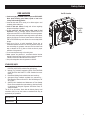 5
5
-
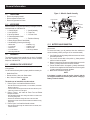 6
6
-
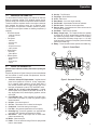 7
7
-
 8
8
-
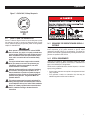 9
9
-
 10
10
-
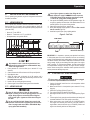 11
11
-
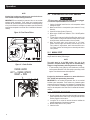 12
12
-
 13
13
-
 14
14
-
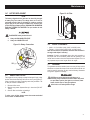 15
15
-
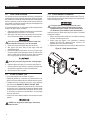 16
16
-
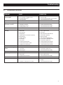 17
17
-
 18
18
-
 19
19
-
 20
20
-
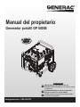 21
21
-
 22
22
-
 23
23
-
 24
24
-
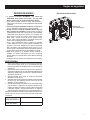 25
25
-
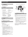 26
26
-
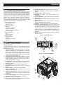 27
27
-
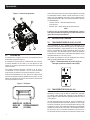 28
28
-
 29
29
-
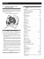 30
30
-
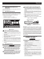 31
31
-
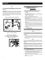 32
32
-
 33
33
-
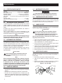 34
34
-
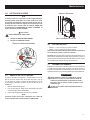 35
35
-
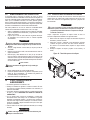 36
36
-
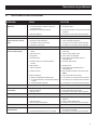 37
37
-
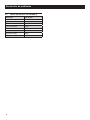 38
38
-
 39
39
-
 40
40


Generac GP8000E 006931R0 Manual de usuario
- Categoría
- Generadores de poder
- Tipo
- Manual de usuario
en otros idiomas
- English: Generac GP8000E 006931R0 User manual