CHAUVIN ARNOUX J93 CURRENT CLAMP Manual de usuario
- Categoría
- Medición
- Tipo
- Manual de usuario

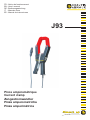
Pince ampèremétrique
Current clamp
Zangestromwandler
Pinza amperometricha
Pinza amperimétrica
FR - Notice de fonctionnement
EN - User’s manual
DE - Bedienungsanleitung
IT - Manuale d’uso
ES - Manual de instrucciones
J93

2
ATTENTION, risque de DANGER ! L’opérateur doit consulter la présente notice à chaque fois que ce symbole de
danger est rencontré.
Appareil protégé par une isolation double.
Application ou retrait autorisé sur les conducteurs nus sous tension dangereuse. Capteur de courant type A selon IEC
IEC/EN 61010-2-032 ou BS EN 61010-2-032.
ATTENTION, risque de choc électrique. La tension appliquée sur les pièces marquées de ce symbole peut être dan-
gereuse.
Pile.
Le marquage CE indique la conformité à la Directive européenne Basse Tension 2014/35/UE, à la Directive Compatibilité
Électromagnétique 2014/30/UE et à la Directive sur la Limitation des Substances Dangereuses RoHS 2011/65/UE et
2015/863/UE.
Le marquage UKCA atteste la conformité du produit avec les exigences applicables dans le Royaume-Uni, notamment
dans les domaines de la Sécurité en Basse Tension, de la Compatibilité Électromagnétique et de la Limitation des
Substances Dangereuses.
à la directive DEEE 2012/19/UE. Ce matériel ne doit pas être traité comme un déchet ménager.
La catégorie de mesure IV correspond aux mesurages réalisés à la source de l’installation basse tension.
Exemple : arrivée d’énergie, compteurs et dispositifs de protection.
La catégorie de mesure III correspond aux mesurages réalisés dans l’installation du bâtiment.
La catégorie de mesure II correspond aux mesurages réalisés sur les circuits directement branchés à l’installation basse tension.
Exemple : alimentation d’appareils électrodomestiques et d’outillage portable.
FRANÇAIS
Vous venez d’acquérir une pince ampèremétrique J93
être utilisée avec les analyseurs de puissances et d’énergie PEL1XX ou CA 83XX et CA 843X version 4 ou au-dessus.
Pour obtenir le meilleur service de votre appareil :
attentivement cette notice de fonctionnement,
les précautions d’emploi.
English ........................................................................................................................................................... 15
Deutsch .......................................................................................................................................................... 28
Italiano ............................................................................................................................................................ 41
Español ........................................................................................................................................................... 54

3
SOMMAIRE
1. PRÉSENTATION ..................................................................................................................................................................... 4
2. UTILISATION ........................................................................................................................................................................... 5
2.1. Mise en route .................................................................................................................................................................. 5
2.2. Mesure ............................................................................................................................................................................ 5
2.3. Arrêt ................................................................................................................................................................................ 6
3. CARACTÉRISTIQUES............................................................................................................................................................ 7
3.1. Conditions de référence ................................................................................................................................................. 7
3.2. Caractéristiques électriques ........................................................................................................................................... 7
3.3. Variations dans le domaine d’utilisation .......................................................................................................................... 8
3.4. Courbes typiques ............................................................................................................................................................ 8
3.5. Alimentation ...................................................................................................................................................................11
3.6. Conditions d’environnement ..........................................................................................................................................11
3.7. Caractéristiques constructives .......................................................................................................................................11
3.8. Conformité aux normes internationales ........................................................................................................................ 12
3.9. Compatibilité électromagnétique (CEM) ....................................................................................................................... 12
4. MAINTENANCE ..................................................................................................................................................................... 13
4.1. Nettoyage ..................................................................................................................................................................... 13
4.2. Remplacement de la pile .............................................................................................................................................. 13
5. GARANTIE ............................................................................................................................................................................ 14
6. ÉTAT DE LIVRAISON ........................................................................................................................................................... 14
PRÉCAUTIONS D’EMPLOI
Ces pinces sont conformes aux normes de sécurité IEC/EN 61010-2-032 ou BS EN 61010-2-032 pour des tensions de 300 V par
rapport à la terre en catégorie IV ou 600 V en catégorie III.
Le non-respect des consignes de sécurité peut entraîner un risque de choc électrique, de feu, d’explosion, de destruction de
l’appareil et des installations.
d’emploi. Une bonne connaissance et une pleine conscience des risques des dangers électriques est indispensable pour toute
utilisation de cet appareil.
par conséquent en danger.
N’utilisez pas la pince sur des réseaux de tensions ou de catégories supérieures à celles mentionnées.
N’utilisez pas la pince si elle semble endommagée, incomplète ou mal fermée.
(même partiellement) doit être consigné pour réparation ou pour mise au rebut.
Utilisez systématiquement des protections individuelles de sécurité.
Ne placez pas les doigts au-delà de la garde physique.

4
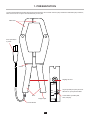
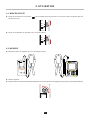
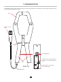
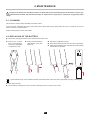
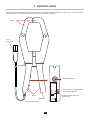
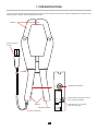
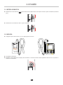
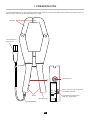
1. PRÉSENTATION
5000A
500A
ZERO
Stop
Test
MARCHE
SORTIE
ZERO
ON
OFF
300 V CAT IV
600 V CAT III
Mâchoires.
Garde.
4 points.
Cordon blindé.
Réglage du zéro.
Voyant qui indique que la pince est
allumée ou que la pile est faible.
Commutateur 3 position (ON,
OFF, test pile).
Trappe à pile.
Bras.

5
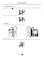
2. UTILISATION
5000A
500A
ZERO
Stop
Test
MARCHE
SORTIE
ZERO
ON
OFF
300 V CAT IV
600 V CAT III
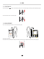
2.1. MISE EN ROUTE
Placez le commutateur sur la position -
placée (voir § 4.2).
5000A
500A
ZERO
Stop
Test
MARCHE
SORTIE
ZERO
ON
OFF
300 V CAT IV
600 V CAT III
Placez le commutateur sur la position ON. Le voyant s’allume.
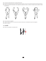
2.2. MESURE
Branchez la pince sur l’appareil, sur l’une des entrées courant.
V1 V2 V3 N I1 I2 I3
MODEL PEL 103
POWER & ENERGY LOGGER
Allumer l’appareil.
5000A
500A
ZERO
Stop
Test
MARCHE
SORTIE
ZERO
ON
OFF
300 V CAT IV
600 V CAT III
W
?
C.A 8336
POWER & QUALITY ANALYSER
QUALI
STAR
+

6
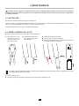
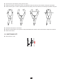
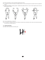
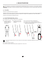
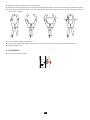
Ouvrez les mâchoires de la pince en rapprochant les bras.
Enserrez le conducteur parcouru par le courant à mesurer. Il ne doit y avoir qu’un seul conducteur dans les mâchoires de la pince.
des mâchoires.
Lisez la mesure sur l’appareil.
Éteignez l’appareil.
2.3. ARRÊT
Placez le commutateur sur la position OFF.
5000A
500A
ZERO
Stop
Test
MARCHE
SORTIE
ZERO
ON
OFF
300 V CAT IV
600 V CAT III

7
3. CARACTÉRISTIQUES
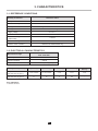
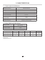
3.1. CONDITIONS DE RÉFÉRENCE
Température 23 ± 5 °C
Humidité relative 20 à 75 % HR
Signal DC Avec un signal AC dont le facteur de distorsion est < 0,1%
Signal AC 45 à 65 Hz avec un signal DC < 0,1 %
Tension d’alimentation 9 V ± 0,1 V
Champ électrique extérieur nul
Champ magnétique DC extérieur
(champ terrestre) < 40 A/m
Champ magnétique AC extérieur nul
Position du conducteur centré dans le tore de mesure
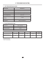
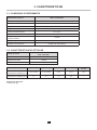
3.2. CARACTÉRISTIQUES ÉLECTRIQUES
50 A - 3 500 Aac
Sensibilité 1 V / 3 500 A
Impédance de sortie ≥ 100 kW
Fréquence DC à 3 kHz (-3 dB typique)
AC/DC) [50 - 100[ [100 - 500[ [500 - 2 000[ [2 000 - 3 500] ]3 500 - 5 000]
DC
Erreur d’amplitude
(voir la courbe au § 3.4.1) ± 2% ± 2,5 A ± 1,5% ± 2,5 A ± 1% ± 1% ± 1%
Erreur de phase
(voir la courbe au § 3.4.2) 4° 2° 1° 1,5° -
± 200 A sur 25 tours

8
3.3. VARIATIONS DANS LE DOMAINE D’UTILISATION
Température -10 à + 55 °C < 0,7 % / 10 °C
Humidité relative 10 à 90% HR < 0,7 %
Réponse en fréquence DC à 2 kHz Voir la courbe au § 3.4.4
Déphasage DC à 2 kHz Voir la courbe au § 3.4.5
Position du conducteur dans le
capteur Position quelconque 1< ± 2 %
Conducteur en contact avec les
mâchoires 2
Tension pile de 6,5 à 10 V ± 2,25 A typique
Rémanence à 5 000 A < 2 A
Champ magnétique terrestre < 0,5 A
1 : Essai réalisé avec un câble de 40 x 30 mm² et un courant de 3 500 A à 50 Hz. L’erreur en % est le rapport de la variation
maximale sur la valeur moyenne.
2 : Test réalisé avec un courant de 300 A à 50 Hz.
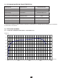
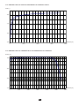
3.4. COURBES TYPIQUES
3.4.1. ERREUR TYPIQUE DE LINÉARITÉ EN AC EN FONCTION DU COURANT À 50 HZ
-1,2
-1,0
-0,8
-0,6
-0,4
-0,2
0,0
0,2
0,4
0 1000 2000 3000 4000
Erreur (%)
Courant (A)

9
3.4.2. ERREUR TYPIQUE DE PHASE EN FONCTION DU COURANT À 50 HZ
-3,5
-2,5
-1,5
-0,5
0 1000 2000 3000 4000
Phase (°)
Courant (A)
3.4.3. ERREUR TYPIQUE DE LINÉARITÉ EN DC EN FONCTION DU COURANT
-7,5
-5,0
-2,5
0,0
0 1000 2000 3000 4000 5000 6000
Erreur (%)
Courant (A)

10
Erreur (%)
3.4.4. ERREUR TYPIQUE D’AMPLITUDE EN FONCTION DE LA FRÉQUENCE
-35
-30
-25
-20
-15
-10
-5
0
5
1 10 100 1000 10000
Fréquence (Hz)
3.4.5. ERREUR TYPIQUE DE PHASE EN FONCTION DE LA FRÉQUENCE
Phase (°)
-10
-5
0
5
10
1 10 100 1000 10000
Fréquence (Hz)

11
3.5. ALIMENTATION
L’alimentation de la pince est réalisée par une pile 9 V alcaline (type 6LF22, 6LR61 ou NEDA 1604).
La tension nominale de fonctionnement se situe entre 6,5 et 10 V.
L’autonomie est de 70 heures. La consommation typique est de 11 mA.
Lors du test pile, si le voyant s’allume, la pince peut être utilisée.
Lorsque le voyant ne s’allume plus, il est nécessaire de remplacer la pile (voir § 4.2).
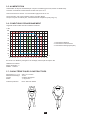
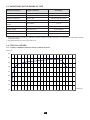
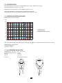
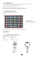
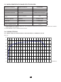
3.6. CONDITIONS D’ENVIRONNEMENT
L’appareil doit être utilisé dans les conditions suivantes :
% HR
100
90
80
70
60
50
40
30
20
10
0
-50 -40 -30 -20 -10 0 10 20 30 40 50 60 70 80 90
°C
95
75
18 28 35 55
3211 : Domaine de référence
2 : Domaine de fonctionnement
3 : Domaine de stockage (sans pile)
Utilisation en intérieur.
Degré de pollution : 2.
Altitude : < 2000 m.
3.7. CARACTÉRISTIQUES CONSTRUCTIVES
Dimensions (L x l x H) 336 x 127 x 42 mm
Diamètre d’enserrage 72 mm
Cordon 3 mètres de longueur
Masse 1,7 kg environ
Indice de protection : IP 20 selon IEC 60529
72
74

12
3.8. CONFORMITÉ AUX NORMES INTERNATIONALES
Sécurité électrique selon IEC/EN 61010-2-032 ou BS EN 61010-2-032 pour les capteurs de type A.
Tension maximale assignée : 300 V CAT. IV ou 600 V CAT. III.
3.9.
Émission et immunité en milieu industriel selon IEC/EN 61326-1 ou BS EN 61326-1, sauf pour l’immunité au champ électrique
avec un critère B .

13
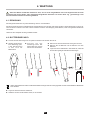
4. MAINTENANCE
4.1. NETTOYAGE
Déconnectez tout branchement de la pince et éteignez-la.
sec ou de l’air pulsé. N’utilisez pas d’alcool, de solvant ou d’hydrocarbure.
Maintenez les entrefers de la pince en parfait état de propreté.
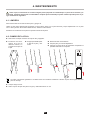
4.2. REMPLACEMENT DE LA PILE
Les piles et les accumulateurs usagés ne doivent pas être traités comme des déchets ménagers. Rapportez-les au point
de collecte approprié pour le recyclage.
Placez ensuite la cale.
Introduisez un outil,
de diamètre 3 mm au
maximum, dans le trou
de la trappe à pile.
Poussez pour déverrouil-
ler la trappe à pile puis
faites-la glisser.
Retirez-la entièrement à la main.
Sortez la pile et la cale du logement.
Placez la nouvelle pile dans le logement en respectant
la polarité indiquée sur l’étiquette.
BEFORE OPENING
CASE TO AVOID
ELECTRIC SHOCKS
REMOVE
THE CLAMP FROM
ALL CONDUCTORS
AND REMOVE
THE OUTPUT
WARNING
9 V
6LF22
6LR61
NEDA 1604

14
5. GARANTIE
Notre garantie s’exerce, sauf stipulation expresse, pendant après la date de mise à disposition du matériel. L’extrait de
nos Conditions Générales de Vente est communiqué sur demande.
La garantie ne s’applique pas suite à :
une utilisation inappropriée de l'équipement ou à une utilisation avec un matériel incompatible ;
-
tionnement ;
des dommages dus à des chocs, chutes ou inondations.
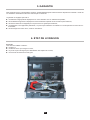
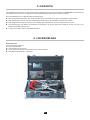
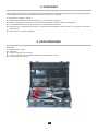
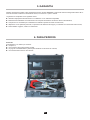
6. ÉTAT DE LIVRAISON
Pince J93
Livré dans une mallette contenant :
une pile 9 V,
une attache velcro pour ranger le cordon,
une notice de fonctionnement 5 langues.

15
WARNING, risk of DANGER! The operator must refer to these instructions whenever this danger symbol appears.
Equipment protected by double insulation.
Application or withdrawal authorized on bare conductors containing dangerous voltages. Type A current sensor as per
IEC/EN 61010-2-032 or BS EN 61010-2-032.
WARNING! Risk of electric shock. The voltage at the parts marked with this symbol may be dangerous.
Battery.
The CE marking indicates compliance with the European Low Voltage Directive (2014/35/EU), Electromagnetic Compatibility
Directive (2014/30/EU), and Restriction of Hazardous Substances Directive (RoHS, 2011/65/EU and 2015/863/EU).
particular as regards Low-Voltage Safety, Electromagnetic Compatibility, and the Restriction of Hazardous Substances.
The rubbish bin with a line through it indicates that, in the European Union, the product must undergo selective disposal
in compliance with Directive WEEE 2012/19/UE. This equipment must not be treated as household waste.
Measurement category IV corresponds to measurements taken at the source of low-voltage installations.
Example: power feeders, counters and protection devices.
Measurement category III corresponds to measurements on building installations.
Measurement category II corresponds to measurements taken on circuits directly connected to low-voltage installations.
Example: power supply to electro-domestic devices and portable tools.
PRECAUTIONS FOR USE
Those current clamps comply with safety standards IEC/EN 61010-2-032 or BS EN 61010-2-032 for voltages of 300 V in category
IV or 600 V category III.
installations.
The operator and/or the responsible authority must carefully read and clearly understand the various precautions to be taken
in use. Sound knowledge and a keen awareness of electrical hazards are essential when using this instrument.
Do not use the clamp on networks at higher voltages or in higher categories than those mentioned.
Do not use the clamp if it seems to be damaged, incomplete, or incorrectly closed.
Before each use, check the condition of the insulation on the leads and housing. Any item of which the insulation is deteriorated
(even partially) must be set aside for repair or scrapping.
Use personal protection equipment systematically.
All troubleshooting and metrological checks must be performed by competent and accredited personnel.
ENGLISH
Thank you for purchasing a J93 current clamp. This clamp is design for use with power and energy analyzers: PEL1XX or CA
83XX and C.A 843X version 4 or higher.
For best results from your current clamp:
these operating instructions carefully,
the precautions for use.

16
CONTENTS
1. PRESENTATION ................................................................................................................................................................... 17
2. USE ......................................................................................................................................................................................... 18
2.1. Starting up .................................................................................................................................................................... 18
2.2. Measurement ................................................................................................................................................................ 18
................................................................................................................................................................. 19
3. CHARACTERISTICS .............................................................................................................................................................. 20
3.1. Reference conditions .................................................................................................................................................... 20
3.2. Electrical characteristics ............................................................................................................................................... 20
3.3. Variations in the range of use ....................................................................................................................................... 21
3.4. Typical curves ............................................................................................................................................................... 21
3.5. Power supply ................................................................................................................................................................ 24
3.6. Environmental conditions ............................................................................................................................................. 24
........................................................................................................................................... 24
3.8. Conformity to international standards ........................................................................................................................... 25
3.9. Electromagnetic compatibility (EMC) ............................................................................................................................ 25
4. MAINTENANCE ...................................................................................................................................................................... 26
4.1. Cleaning ....................................................................................................................................................................... 26
4.2. Replacing of the battery ................................................................................................................................................ 26
5. WARRANTY .......................................................................................................................................................................... 27
6. TO ORDER .............................................................................................................................................................................. 27

17
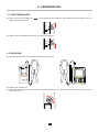
1. PRESENTATION
5000A
500A
ZERO
Stop
Test
MARCHE
SORTIE
ZERO
ON
OFF
300 V CAT IV
600 V CAT III
Guard.
plug.
Shielded cord.
Indicator that indicates that the
clamp is on or that the battery is
low.
Three-position switch (ON,
OFF, battery test).
Battery com-
partment cover.
Arm.

18
2. USE
5000A
500A
ZERO
Stop
Test
MARCHE
SORTIE
ZERO
ON
OFF
300 V CAT IV
600 V CAT III
2.1. STARTING UP
Set the switch to n order to check that the battery is OK. If the indicator lights, the battery must be replaced (see §4.2).
5000A
500A
ZERO
Stop
Test
MARCHE
SORTIE
ZERO
ON
OFF
300 V CAT IV
600 V CAT III
Set the switch to ON. The indicator lights.
2.2. MEASUREMENT
Connect the clamp to the device, on one of the current inputs.
Switch on the device.
5000A
500A
ZERO
Stop
Test
MARCHE
SORTIE
ZERO
ON
OFF
300 V CAT IV
600 V CAT III
V1 V2 V3 N I1 I2 I3
MODEL PEL 103
POWER & ENERGY LOGGER
W
?
C.A 8336
POWER & QUALITY ANALYSER
QUALI
STAR
+

19
Read the measurement on the device.
When the measurement is over, open the clamp and withdraw the conductor. Then disconnect the clamp from the device.
2.3. SWITCHING OFF
Set the switch to OFF.
5000A
500A
ZERO
Stop
Test
MARCHE
SORTIE
ZERO
ON
OFF
300 V CAT IV
600 V CAT III

20
3. CHARACTERISTICS
3.1. REFERENCE CONDITIONS
Temperature 23±5°C
Relative humidity 20 to 75% RH
DC signal With an AC signal of which the distortion factor is <0.1%
AC signal 45 to 65 Hz with a DC signal <0.1%
Supply voltage 9 V ± 0.1 V
Zero
< 40 A/m
Zero
Position of the conductor centred in the measurement ring
3.2. ELECTRICAL CHARACTERISTICS
50 A - 3 500 A
50 A - 5 000 A
Sensitivity 1 V / 3 500 A
Output impedance ≥ 100 kW
Frequency DC to 3 kHz (-3 dB typical)
AC/DC) [50 - 100[ [100 - 500[ [500 - 2 000[ [2 000 - 3 500] ]3 500 - 5 000]
DC
Amplitude error
(see the curve in §3.4.1) ± 2% ± 2.5 A ± 1.5% ± 2.5 A ± 1% ± 1% ± 1%
Phase error
(see the curve in §3.4.2) 4° 2° 1° 1.5° -
± 200 A in 25 turns

21
3.3. VARIATIONS IN THE RANGE OF USE
Temperature -10 to + 55 °C < 0,7 % / 10 °C
Relative humidity 10 to 90% HR < 0,7 %
Frequency response DC at 2 kHz See the curve in § 3.4.4
Phase shift DC at 2 kHz See the curve in § 3.4.5
Position of the conductor in the
sensor Any position 1< ± 2 %
2
Battery voltage from 6,5 to 10 V ± 2,25 A typique
Remanence at 5 000 A < 2 A
< 0,5 A
1: Test performed with a 40x30 mm² cable and a current of 3500 A at 50 Hz. The error in % is the ratio of the maximum variation
to the mean value.
2: Test performed with a current of 300 A at 50 Hz.
3.4. TYPICAL CURVES
3.4.1. TYPICAL LINEARITY ERROR IN AC VS CURRENT AT 50HZ
-1,2
-1,0
-0,8
-0,6
-0,4
-0,2
0,0
0,2
0,4
0 1000 2000 3000 4000
Error (%)
Current (A)

22
3.4.2. TYPICAL PHASE ERROR VS CURRENT AT 50 HZ
-3,5
-2,5
-1,5
-0,5
0 1000 2000 3000 4000
Phase (°)
Current (A)
3.4.3. TYPICAL LINEARITY ERROR IN DC VS CURRENT
-7,5
-5,0
-2,5
0,0
0 1000 2000 3000 4000 5000 6000
Error (%)
Current (A)

23
Erreur (%)
3.4.4. TYPICAL AMPLITUDE ERROR VS FREQUENCY
-35
-30
-25
-20
-15
-10
-5
0
5
1 10 100 1000 10000
Frequency (Hz)
3.4.5. TYPICAL PHASE ERROR VS FREQUENCY
Phase (°)
-10
-5
0
5
10
1 10 100 1000 10000
Frequency (Hz)

24
3.5. POWER SUPPLY
The power supply of the clamp is provided by a 9 V alkaline battery (type 6LF22, 6LR61, or NEDA 1604).
The nominal operating voltage is between 6.5 and 10 V.
The battery life is 70 hours. The typical consumption is 11 mA.
During the battery test, if the indicator lights, the clamp can be used.
When the indicator no longer lights, the battery must be replaced (see §4.2).
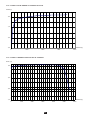
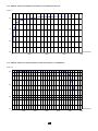
3.6. ENVIRONMENTAL CONDITIONS
The device must be used under the following conditions:
% RH
100
90
80
70
60
50
40
30
20
10
0
-50 -40 -30 -20 -10 0 10 20 30 40 50 60 70 80 90
°C
95
75
18 28 35 55
3211: Reference range
2: Operating range
3: Storage range (without battery)
Indoor use.
Degree of pollution: 2.
Altitude: <2000m.
3.7. CONSTRUCTION SPECIFICATIONS
Dimensions (L x W x H) 336 x 127 x 42 mm
Clamping diameter 72 mm
Cord 3 metres long
Weight approx. 1.7kg
Protection index: IP20 according to IEC 60529
72
74

25
3.8. CONFORMITY TO INTERNATIONAL STANDARDS
Electrical safety according to IEC/EN 61010-2-032 or BS EN 61010-2-032 for type A sensors.
Maximum applicable voltage: 300V CAT. IV or 600V CAT. III.
3.9.
Emissions and immunity in an industrial environment in accordance with IEC/EN 61326-1 or BS EN 61326-1, except for immunity

26
4. MAINTENANCE
-
4.1. CLEANING
Disconnect the current clamp completely and switch it OFF.
Use a soft cloth, dampened with soapy water. Rinse with a damp cloth and dry rapidly with a dry cloth or forced air. Do not use
alcohol, solvents, or hydrocarbons.
4.2. REPLACING OF THE BATTERY
Spent batteries must not be treated as ordinary household waste. Take them to the appropriate recycling collection point.
Then place the shim.
Put the battery compartment cover back in the slide and push it in until you hear a click.
Insert a tool, not more
than 3 mm in diameter,
in the hole in the battery
compartment cover.
Push to unlock the battery
compartment cover, then
Remove it completely by hand.
Remove the battery and the shim from the compartment.
Place the new battery in the compartment with the polarity
as indicated on the label.
BEFORE OPENING
CASE TO AVOID
ELECTRIC SHOCKS
REMOVE
THE CLAMP FROM
ALL CONDUCTORS
AND REMOVE
THE OUTPUT
WARNING
9 V
6LF22
6LR61
NEDA 1604

27
5. WARRANTY
Except as otherwise stated, our warranty is valid for starting from the date on which the equipment was sold. Extract
from our General Conditions of Sale provided on request.
The warranty does not apply in the following cases:
Inappropriate use of the equipment or use with incompatible equipment;
Work done on the device by a person not approved by the manufacturer;
6. TO ORDER
J93 clamp
Delivered in a carrying case containing:
one 9V battery,
one Velcro fastener for the lead,
a set of 12 inserts and rings to identify the current sensors,
a user manual in 5 languages.

28
zu Rate zu ziehen.
Das Gerät ist durch eine doppelte Isolierung geschützt.
Anbringung oder Abnahme zulässig an Leitungen unter Gefährdungsspannung. Stromsonde Typ A gemäß IEC/EN
61010-2-032 bzw. BS EN 61010-2-032.
ACHTUNG! Gefahr eines elektrischen Stromschlags. Mit diesem Symbol gekennzeichnete Teile stehen möglicherweise
unter Gefahrenspannung!
Batterie.
Die CE-Kennzeichnung bestätigt die Übereinstimmung mit der europäischen Niederspannungsrichtlinie 2014/35/EU,
der Richtlinie zur elektromagnetischen Verträglichkeit 2014/30/EU, sowie der RoHS-Richtlinie zur Beschränkung der
Mit der UKCA-Kennzeichnung erklärt der Hersteller die Übereinstimmung des Produkts mit Vorschriften des Vereinigten
Königreichs, insbesondere in den Bereichen Niederspannungssicherheit, elektromagnetische Verträglichkeit und
Der durchgestrichene Mülleimer bedeutet, dass das Produkt in der europäischen Union gemäß der WEEE-Richtlinie
2012/19/UE einer getrennten Elektroschrott-Verwertung zugeführt werden muss. Das Produkt darf nicht als
Haushaltsmüll entsorgt werden.
Messkategorie IV entspricht Messungen an der Quelle der Niederspannungsinstallation.
Beispiel: Hauptanschluss, Zähler und primärer Überstromschutz.
Messkategorie III entspricht Messungen in der Gebäudeinstallation.
Beispiel: Verteileranschluss, Leistungsschalter, stationäre Instrumente fest am Verteiler.
Messkategorie II entspricht Messungen an Stromkreisen, die elektrisch über Stecker direkt mit dem Niederspannungsnetz
verbunden sind.
Beispiel: Stromversorgung von Haushaltsgeräten oder tragbaren Elektrowerkzeugen.
SICHERHEITSHINWEISE
Die Strommesszangen entsprechen den Sicherheitsnormen IEC/EN 61010-2-032 bzw. BS EN 61010-2-032 für Spannungen bis
300 V gegen Erde in der Messkategorie IV bzw. 600 V / Messkategorie III.
Die Nichtbeachtung der Sicherheitshinweise kann zu Gefahren durch elektrische Schläge, durch Brand oder Explosion, sowie zur
Zerstörung des Geräts und der Anlage führen.
Der Benutzer bzw. die verantwortliche Stelle müssen die verschiedenen Sicherheitshinweise sorgfältig lesen und gründlich
unverzichtbar.
Wenn die Zange-
währleistet sein und eine Gefahr für den Benutzer entstehen
Verwenden Sie die Strommesszange niemals an Netzen mit höheren Spannungen oder Messkategorien als den angegebenen.
DEUTSCH
Sie haben eine erstanden, wir danken Ihnen für Ihr Vertrauen. Diese Zange ist für den Einsatz mit Leistungs-
und Energie-Logger PEL1XX sowie mit CA 83XX und C.A 843X ab Version 4 geeignet.
Um die optimale Benutzung Ihres Strommesszange zu gewährleisten, bitten wir Sie :
diese Bedienungsanleitung
die Benutzungshinweise .

29
INHALTSVERZEICHNIS
1. VORSTELLUNG .................................................................................................................................................................... 30
2. VERWENDUNG ..................................................................................................................................................................... 31
2.1. Inbetriebnahme ............................................................................................................................................................. 31
2.2. Messung ....................................................................................................................................................................... 31
2.3. Abschalten .................................................................................................................................................................... 32
3. TECHNISCHE DATEN .......................................................................................................................................................... 33
3.1. Referenzbedingungen .................................................................................................................................................. 33
3.2. Elektrische Daten ......................................................................................................................................................... 33
3.3. Schwankungen im Einsatzbereich ................................................................................................................................ 34
3.4. Typische Kurven ........................................................................................................................................................... 34
3.5. Versorgung ................................................................................................................................................................... 37
3.6. Umgebungsbedingungen ............................................................................................................................................. 37
3.7. Allgemeine Baudaten .................................................................................................................................................... 37
3.8. Konformität mit internationalen Normen ....................................................................................................................... 38
3.9. Elektromagnetische Verträglichkeit (EMV) ................................................................................................................... 38
4. WARTUNG ............................................................................................................................................................................. 39
4.1. Reinigung ..................................................................................................................................................................... 39
4.2. Batteriewechsel ............................................................................................................................................................ 39
5. GARANTIE ............................................................................................................................................................................ 40
6. LIEFERUMFANG ................................................................................................................................................................... 40
Die Zange nicht verwenden, wenn sie beschädigt, unvollständig oder schlecht geschlossen ist.
-
weise beschädigter Isolierung müssen für eine Reparatur oder für die Entsorgung ausgesondert werden.
Verwenden Sie stets die erforderliche persönliche Schutzausrüstung.
Fassen Sie die Zange immer nur hinter dem Fingerschutz an.
Reparaturen und messtechnische Überprüfungen dürfen nur durch zugelassenes Fachpersonal erfolgen.

30
1. VORSTELLUNG
5000A
500A
ZERO
Stop
Test
MARCHE
SORTIE
ZERO
ON
OFF
300 V CAT IV
600 V CAT III
Backen.
Fingerschutz.
4-Pol-
Messspitze.
Geschirmte Leitung.
Nullpunkteinstellung.
LED-Anzeige bei Gerätebetrieb
und schwacher Batterie.
Dreifachschalter (ON, OFF,
Batterietest)
Batteriefach.

31
2. VERWENDUNG
5000A
500A
ZERO
Stop
Test
MARCHE
SORTIE
ZERO
ON
OFF
300 V CAT IV
600 V CAT III
2.1. INBETRIEBNAHME
Stellen Sie zuerst den Schalter auf
Batterie gewechselt werden.
5000A
500A
ZERO
Stop
Test
MARCHE
SORTIE
ZERO
ON
OFF
300 V CAT IV
600 V CAT III
Stellen Sie den Drehschalter auf Stellung ON. Die LED leuchtet auf.
2.2. MESSUNG
Schließen Sie die Zange über einen Stromeingang an das Gerät an.
Schalten Sie das Gerät ein.
Stellen Sie nun den Nullpunkt ein. Dazu drehen Sie den Nullpunktknopf und behalten dabei die Geräteanzeige im Auge, bis
Null angezeigt wird.
5000A
500A
ZERO
Stop
Test
MARCHE
SORTIE
ZERO
ON
OFF
300 V CAT IV
600 V CAT III
V1 V2 V3 N I1 I2 I3
MODEL PEL 103
POWER & ENERGY LOGGER
W
?
C.A 8336
POWER & QUALITY ANALYSER
QUALI
STAR
+

32
werden.
Lassen Sie die Backen vorsichtig zugehen. Optimale Messqualität erzielt man, wenn der Leiter möglichst genau durch die
Mitte der Backen verläuft.
Lesen Sie die Messung vom Gerät ab.
vom Gerät ab und schalten dieses ab.
2.3. ABSCHALTEN
Stellen Sie den Drehschalter auf Stellung OFF.
5000A
500A
ZERO
Stop
Test
MARCHE
SORTIE
ZERO
ON
OFF
300 V CAT IV
600 V CAT III

33
3. TECHNISCHE DATEN
3.1. REFERENZBEDINGUNGEN
Temperatur 23 ±5°C
Relative Luftfeuchte 20 bis 75% r.F.
DC-Signal Bei AC-Signal mit Verzerrungsfaktor <0,1%
AC-Signal 45 - 65Hz bei DC-Signal <0,1%
Versorgungsspannung 9 V ± 0,1 V
Elektrische Feldstärke Null
Magnetfeldstärke DC
(Erdfeld) < 40 A/m
Magnetfeldstärke AC Null
Leiterposition Mittig in der Messspule
3.2. ELEKTRISCHE DATEN
50 A - 3 500 A
50 A - 5 000 A
1 V / 3 500 A
Ausgangsimpedanz ≥ 100 kW
Frequenz DC bei 3 kHz (typische -3 dB)
[50 - 100[ [100 - 500[ [500 - 2 000[ [2 000 - 3 500] ]3 500 - 5 000]
nur DC
Amplitudenfehler
(siehe Kurve Kap. 3.4.1) ± 2% ± 2,5 A ± 1,5% ± 2,5 A ± 1% ± 1% ± 1%
Phasenfehler
(siehe Kurve Kap. 3.4.2) 4° 2° 1° 1,5° -
± 200 A / 25 Windungen

34
3.3. SCHWANKUNGEN IM EINSATZBEREICH
Temperatur -10 bis +55°C <0,7%/10°C
Relative Luftfeuchte 10 bis 90% r.F. < 0.7%
Frequenzgang DC bei 2kHz siehe Kurve Kap. 3.4.4
Phasenverschiebung DC bei 2kHz siehe Kurve Kap. 3.4.5
Leiterposition im Stromwandler beliebige Position 1 <±2%
Angrenzender Leiter Leiter liegt an Backen an 2
Batteriespannung 6,5 bis 10 V typische ± 2,25 A
Remanenz bei 5 000 A < 2 A
Erdmagnetfeld < 0,5 A
1: Test mit einem 40x30mm² Kabel und 3500 A / 50Hz Strom. Unsicherheit in %: Verhältnis der max. Abweichung zum Mittelwert.
2: Test mit 300 A / 50 Hz Strom.
3.4. TYPISCHE KURVEN
3.4.1. TYPISCHER LINEARITÄTSFEHLER AC / STROM BEI 50 HZ
-1,2
-1,0
-0,8
-0,6
-0,4
-0,2
0,0
0,2
0,4
0 1000 2000 3000 4000
Fehler (%)
Strom (A)

35
3.4.2. TYPISCHE PHASENVERSCHIEBUNG / STROM BEI 50 HZ
-3,5
-2,5
-1,5
-0,5
0 1000 2000 3000 4000
Phasen (°)
Strom (A)
3.4.3. TYPISCHER LINEARITÄTSFEHLER DC / STROM
-7,5
-5,0
-2,5
0,0
0 1000 2000 3000 4000 5000 6000
Fehler (%)
Strom (A)

36
Fehler (%)
3.4.4. TYPISCHE AMPLITUDENABWEICHUNG / FREQUENZ
-35
-30
-25
-20
-15
-10
-5
0
5
1 10 100 1000 10000
Frequenz (Hz)
3.4.5. TYPISCHE PHASENVERSCHIEBUNG / FREQUENZ
Phasen (°)
-10
-5
0
5
10
1 10 100 1000 10000
Frequenz (Hz)

37
3.5. VERSORGUNG
Die Strommesszange wird mit einer 9V Alkalibatterie (6LF22, 6LR61, NEDA 1604) versorgt.
Nennbetriebsspannung zwischen 6,5 und 10V.
Betriebsautonomie 70 Stunden. Durchschnittlicher Verbrauch 11 mA.
Leuchtet die LED nicht, muss die Batterie gewechselt werden (siehe Kap. 4.2).
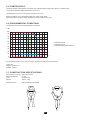
3.6. UMGEBUNGSBEDINGUNGEN
Betriebsbedingungen für das Gerät:
% RF
100
90
80
70
60
50
40
30
20
10
0
-50 -40 -30 -20 -10 0 10 20 30 40 50 60 70 80 90
°C
95
75
18 28 35 55
3211: Referenzbereich
2: Funktionsbereich
3: Lagerbereich (ohne Batterie)
Verwendung nur in Innenräumen
Verschmutzungsgrad: 2.
Höhenlage: <2000m.
3.7. ALLGEMEINE BAUDATEN
Abmessungen (L x B x H) 336 x 127 x 42 mm
Umschließungsdurchmesser 72 mm
Leitung 3 m lang
Gewicht ca. 1,7 kg
Schutzart: IP20 gemäß IEC 60529
72
74

38
3.8. KONFORMITÄT MIT INTERNATIONALEN NORMEN
Elektrische Sicherheit gemäß Norm IEC/EN 61010-2-032 bzw. BS EN 61010-2-032 für Stromwandler Type A.
max. zul. Nennspannung: 300 V KAT. IV oder 600 V KAT. III.
3.9.
Emissivität und Immunität im industriellen Umfeld entsprechen der Norm IEC/EN 61326-1 bzw. BS EN 61326-1, außer Immunität
im elektrischen Feld mit Kriterium B.

39
4. WARTUNG
4.1. REINIGUNG
Das Gerät mit einem leicht mit Seifenwasser angefeuchteten Tuch reinigen. Mit einem feuchten Lappen abwischen und kurz da-
nach mit einem trockenen Tuch oder in einem Luftstrom trocknen. Zur Reinigung weder Alkohol, noch Lösungsmittel oder Benzin
verwenden.
Halten Sie die Luftspalte der Zange tadellos sauber.
4.2. BATTERIEWECHSEL
Akkus oder Batterien sind kein Haushaltsmüll! Bitte entsorgen Sie sie ordnungsgemäß an einer Sammelstelle für Altbatterien
bzw. Altakkus.
Legen Sie dann die Klemme wieder ein.
Schieben Sie den Deckel wieder hinein, bis er einrastet.
Stecken Sie ein höchs-
tens Werkzeug (max.
3 mm Durchmesser)
in das Loch am
Batteriefach.
Drücken Sie das
Werkzeug hinein. Der
Deckel löst sich und Sie
können ihn verschieben.
Nehmen Sie den Deckel mit der Hand ganz herunter.
Nehmen Sie die Batterie und die Klemme aus dem
Gehäuse.
Legen Sie die neue Batterie in das Gehäuse, dabei die
am Schild angezeigte Polarität berücksichtigen.
BEFORE OPENING
CASE TO AVOID
ELECTRIC SHOCKS
REMOVE
THE CLAMP FROM
ALL CONDUCTORS
AND REMOVE
THE OUTPUT
WARNING
9 V
6LF22
6LR61
NEDA 1604

40
5. GARANTIE
Unsere Garantie erstreckt sich, soweit nichts anderes ausdrücklich gesagt ist, auf eine Dauer von nach Überlassung
des Geräts (Auszug aus unseren allgemeinen Geschäftsbedingungen, die Sie gerne anfordern können).
Eine Garantieleistung ist in folgenden Fällen ausgeschlossen:
Bei unsachgemäßer Benutzung des Geräts oder Benutzung in Verbindung mit einem inkompatiblen anderen Gerät.
Nach Änderungen am Gerät, die ohne ausdrückliche Genehmigung des Herstellers vorgenommen wurden.
Nach Anpassungen des Geräts an besondere Anwendungen, für die das Gerät nicht bestimmt ist oder die nicht in der
Bedienungsanleitung genannt sind.
In Fällen von Stößen, Stürzen oder Wasserschäden.
6. LIEFERUMFANG
eine 9V Alkalibatterie,
eine Klettband für die Leitung,
1 Satz 12 Stifte und Ringe zur Kennzeichnung der Stromwandler,
eine Bedienungsanleitung in 5 Sprachen.

41
ATTENZIONE, rischio di PERICOLO! L’operatore deve consultare il presente manuale d’uso ogni volta che vedrà
questo simbolo di pericolo.
Strumento protetto da doppio isolamento.
Applicazione o rimozione su conduttori nudi con tensione pericolosa. Sensore di corrente di tipo A secondo la norma
IEC/EN 61010-2-032 o BS EN 61010-2-032.
ATTENZIONE, rischio di folgorazione. La tensione applicata sui pezzi contrassegnati da questo simbolo può essere
pericolosa.
Pila.
La marcatura CE indica la conformità alla Direttiva europea Bassa Tensione 2014/35/UE, alla Direttiva Compatibilità
Elettromagnetica 2014/30/UE e alla Direttiva sulla Limitazione delle Sostanze Pericolose RoHS 2011/65/UE e 2015/863/UE.
La marcatura UKCA attesta la conformità del prodotto con le esigenze applicabili nel Regno Unito, segnatamente
nei campi della Sicurezza in Bassa Tensione, della Compatibilità Elettromagnetica e della Limitazione delle Sostanze
Pericolose.
-
memente alla direttiva DEEE 2012/19/UE (concernente gli strumenti elettrici e elettronici). Questo materiale non va
la categoria di misura IV corrisponde alle misure realizzate all’origine dell’installazione di bassa tensione.
Esempio: entrata di energia, contatori e dispositivi di protezione.
La categoria di misura III corrisponde alle misure realizzate nell’isntallazione dell’immobile.
La categoria di misura II corrisponde alle misure realizzate sui circuiti direttamente collegate all’installazione di bassa tensione.
Esempio: alimentazione di elettrodomestici e strumentazione portatile.
PRECAUZIONI D’USO
Queste pinze sono conformi alle norme di sicurezza IEC/EN 61010-2-032 o BS EN 61010-2-032 per tensioni di 300 V rispetto alla
terra in categoria IV oppure 600 V in categoria III.
Il mancato rispetto delle indicazioni di sicurezza può causare un rischio di shock elettrico, incendio, esplosione, distruzione dello
strumento e degli impianti.
L’operatore e/o l’autorità responsabile deve leggere attentamente e assimilare le varie precauzioni d’uso. La buona conoscenza
(e la perfetta coscienza) dei rischi correlati all’elettricità è indispensabile per ogni utilizzo di questo strumento.
mettendovi di conseguenza in pericolo
Non utilizzate la pinza su reti di tensione o categorie superiori a quelle menzionate.
Non utilizzate la pinza se sembra danneggiato, incompleto o chiuso male.
è deteriorato (seppure parzialmente) va messo fuori servizio per opportuna riparazione o trasporto in discarica.
ITALIANO
Avete appena acquistato un
progettata per un utilizzo con gli analizzatori di potenza e d’energia PEL1XX oppure CA 83XX e C.A 843X versione 4 o superiore.
Per ottenere le migliori prestazioni dal vostra pinza:
attentamente il presente manuale d’uso.
le precauzioni d’uso.

42
SOMMARIO
1. PRESENTAZIONE ................................................................................................................................................................. 43
2. UTILIZZO ............................................................................................................................................................................... 44
2.1. Messa in marcia ........................................................................................................................................................... 44
2.2. Misura ........................................................................................................................................................................... 44
2.3. Spegnimento ................................................................................................................................................................ 45
3. CARATTERISTICHE ............................................................................................................................................................. 46
3.1. Condizioni di riferimento ............................................................................................................................................... 46
3.2. Caratteristiche elettriche ............................................................................................................................................... 46
3.3. Variazioni nel campo d’utilizzo ...................................................................................................................................... 47
3.4. Curve tipiche ................................................................................................................................................................. 47
3.5. Alimentazione ............................................................................................................................................................... 50
3.6. Condizioni ambientali ................................................................................................................................................... 50
3.7. Caratteristiche costruttive ............................................................................................................................................. 50
3.8. Conformità alle norme internazionali ............................................................................................................................ 51
3.9. Compatibilità elettromagnetica (CEM) .......................................................................................................................... 51
4. MANUTENZIONE .................................................................................................................................................................. 52
4.1. Pulizia ........................................................................................................................................................................... 52
4.2. Sostituzione della pila ................................................................................................................................................... 52
5. GARANZIA ............................................................................................................................................................................ 53
6. PER ORDINARE .................................................................................................................................................................... 53
Utilizzate sistematicamente le protezioni individuali di sicurezza.
Non mettete le dita oltre la protezione di guardia.

43
1. PRESENTAZIONE
5000A
500A
ZERO
Stop
Test
MARCHE
SORTIE
ZERO
ON
OFF
300 V CAT IV
600 V CAT III
Ganasce.
Guardia.
Presa specifica
4 punti.
Cavo schermato.
Regolazione dello zero.
Spia indicante che la pinza è acce-
sa o che la pila è debole.
Commutatore 3 posizioni
(ON, OFF, test pila).
Sportello delle pile.
Braccio.

44
2. UTILIZZO
5000A
500A
ZERO
Stop
Test
MARCHE
SORTIE
ZERO
ON
OFF
300 V CAT IV
600 V CAT III
2.1. MESSA IN MARCIA
Posizionate il commutatore su
§4.2).
5000A
500A
ZERO
Stop
Test
MARCHE
SORTIE
ZERO
ON
OFF
300 V CAT IV
600 V CAT III
Posizionate il commutatore su ON. La spia si accende.
2.2. MISURA
Collegate la pinza allo strumento, su uno degli ingressi di corrente.
Accendere lo strumento.
strumento visualizzerà 0.
5000A
500A
ZERO
Stop
Test
MARCHE
SORTIE
ZERO
ON
OFF
300 V CAT IV
600 V CAT III
V1 V2 V3 N I1 I2 I3
MODEL PEL 103
POWER & ENERGY LOGGER
W
?
C.A 8336
POWER & QUALITY ANALYSER
QUALI
STAR
+

45
Aprite le ganasce della pinza avvicinando i bracci.
Serrate il conduttore percorso dalla corrente da misurare. Un solo conduttore dovrà trovarsi nelle ganasce della pinza.
Richiudete cautamente le ganasce. Per ottimizzare la qualità della misura, posizionate il conduttore per quanto possibile nel
centro delle ganasce.
Leggete la misura sullo strumento.
Spegnete lo strumento.
2.3. SPEGNIMENTO
Posizionate il commutatore su OFF.
5000A
500A
ZERO
Stop
Test
MARCHE
SORTIE
ZERO
ON
OFF
300 V CAT IV
600 V CAT III

46
3. CARATTERISTICHE
3.1. CONDIZIONI DI RIFERIMENTO
Temperatura 23±5°C
Umidità relativa 20 a 75% HR
Segnale DC Con un segnale AC il cui fattore di distorsione è <0,1%
Segnale AC Da 45 a 65 Hz con un segnale DC<0,1%
Tensione d’alimentazione 9 V ± 0,1 V
Campo elettrico esterno Nullo
Campo magnetico DC esterno
(campo terrestre) < 40 A/m
Campo magnetico AC esterno Nullo
Posizione del conduttore Centrato nel toro di misura
3.2. CARATTERISTICHE ELETTRICHE
50 A - 3 500 A
50 A - 5 000 A
Sensibilità 1 V / 3 500 A
Impedenza d’uscita ≥ 100 kW
Frequenza DC a 3kHz (-3dB tipica)
AC/DC) [50 - 100[ [100 - 500[ [500 - 2 000[ [2 000 - 3 500] ]3 500 - 5 000]
DC
Errore d’ampiezza
(osservare la curva del § 3.4.1) ± 2% ± 2,5 A ± 1,5% ± 2,5 A ± 1% ± 1% ± 1%
Errore di fase
(osservare la curva del § 3.4.2) 4° 2° 1° 1,5° -
± 200 A su 25 giri

47
3.3. VARIAZIONI NEL CAMPO D’UTILIZZO
Temperatura -10 a + 55°C <0,7%/10°C
Umidità relativa 10 a 90% HR <0,7%
Risposta in frequenza DC a 2kHz Osservare la curva del §3.4.4
Sfasamento DC a 2kHz Osservare la curva del §3.4.5
Posizione del conduttore nel
sensore Posizione qualsiasi 1 <±2%
Conduttore adiacente Conduttore in contatto con le ga-
nasce 2
Tensione pila de 6,5 a 10 V ± 2,25 A tipica
Rimanenza a 5 000 A < 2 A
Campo magnetico terrestre < 0,5 A
1: Prova realizzata con un cavo di 40 x 30mm² e una corrente di 3500 A a 50Hz. L’errore in % è il rapporto della variazione mas-
sima sul valore medio.
2: Test realizzato con una corrente di 300A a 50Hz.
3.4. CURVE TIPICHE
3.4.1. ERRORE TIPICO DI LINEARITÀ IN AC IN FUNZIONE DELLA CORRENTE A 50HZ
-1,2
-1,0
-0,8
-0,6
-0,4
-0,2
0,0
0,2
0,4
0 1000 2000 3000 4000
Errore (%)
Corrente (A)

48
3.4.2. ERRORE TIPICO DI FASE IN FUNZIONE DELLA CORRENTE A 50HZ
-3,5
-2,5
-1,5
-0,5
0 1000 2000 3000 4000
Fase (°)
Corrente (A)
3.4.3. ERRORE TIPICO DI LINEARITÀ IN DC IN FUNZIONE DELLA CORRENTE
-7,5
-5,0
-2,5
0,0
0 1000 2000 3000 4000 5000 6000
Errore (%)
Corrente (A)

49
Errore (%)
3.4.4. ERRORE TIPICO D’AMPIEZZA IN FUNZIONE DELLA FREQUENZA
-35
-30
-25
-20
-15
-10
-5
0
5
1 10 100 1000 10000
Frequenza (Hz)
3.4.5. ERRORE TIPICO DI FASE IN FUNZIONE DELLA FREQUENZA
Fase (°)
-10
-5
0
5
10
1 10 100 1000 10000
Frequenza (Hz)

50
3.5. ALIMENTAZIONE
L’alimentazione della pinza avviene mediante una pila 9V alcalina (tipo 6LF22, 6LR61 o NEDA 1604).
La tensione nominale di funzionamento si attesta fra 6,5 e 10V.
L’autonomia è di 70 ore. Il consumo tipico è di 11mA.
Durante il test della pila, se la spia si accende, è possibile utilizzare la pinza.
Quando la spia non si accende più, è necessario sostituire la pila (consultare §4.2).
3.6. CONDIZIONI AMBIENTALI
Lo strumento va utilizzato alle seguenti condizioni:
% UR
100
90
80
70
60
50
40
30
20
10
0
-50 -40 -30 -20 -10 0 10 20 30 40 50 60 70 80 90
°C
95
75
18 28 35 55
3211: Campo di riferimento
2: Campo di funzionamento
3: Campo di stoccaggio (senza pila)
Utilizzo all’interno.
Grado di inquinamento: 2.
Altitudine: <2000m.
3.7. CARATTERISTICHE COSTRUTTIVE
Dimensioni (L x l x H) 336 x 127 x 42 mm
Diametro di serraggio 72 mm
Cavo 3 metri di lunghezza
Massa 1,7 kg circa
Indice di protezione: IP20 secondo IEC 60529
72
74

51
3.8. CONFORMITÀ ALLE NORME INTERNAZIONALI
Sicurezza elettrica secondo IEC/EN 61010-2-032 o BS EN 61010-2-032 per i sensori di tipo A.
Tensione massima assegnata: 300V CAT. IV o 600V CAT. III.
3.9.
Emissione e immunità in ambiente industriale secondo IEC/EN 61326-1 o BS EN 61326-1, tranne per l’immunità in campo elettrico
con un criterio B.

52
4. MANUTENZIONE
4.1. PULIZIA
Disinserire completamente la pinza e spegnerla.
utilizzando un panno asciutto oppure un getto d’aria compressa. Si consiglia di non utilizzare alcool, solventi o idrocarburi.
Mantenete i traferri della pinza perfettamente puliti.
4.2. SOSTITUZIONE DELLA PILA
-
tuno riciclo.
In seguito rimettete la zeppetta.
Introducete un attrezzo
(diametro massimo: 3
mm) nel foro dello spor-
tello delle pile.
Spingete lo sportello delle
pile per sbloccarlo e fatelo
scivolare.
Con la mano rimuovetelo completamente.
Estraete la pila e la zeppetta dell’alloggiamento.
Inserite la nuova pila nell’alloggiamento rispettando la
polarità indicata sull’etichetta.
BEFORE OPENING
CASE TO AVOID
ELECTRIC SHOCKS
REMOVE
THE CLAMP FROM
ALL CONDUCTORS
AND REMOVE
THE OUTPUT
WARNING
9 V
6LF22
6LR61
NEDA 1604

53
5. GARANZIA
Salvo stipulazione espressa la nostra garanzia si esercita, a decorrere dalla data di messa a disposizione del materiale.
L’estratto delle nostre Condizioni Generali di Vendita sarà comunicato su domanda.
La garanzia non si applica in seguito a:
Utilizzo inappropriato dello strumento o utilizzo con un materiale incompatibile;
Adattamento ad un’applicazione particolare, non prevista dalla progettazione dello strumento o non indicata nel manuale di
funzionamento;
Danni dovuti a urti, cadute, inondazioni.
6. PER ORDINARE
La valigetta fornita contiene:
una pila 9V,
un attacco Velcro per riporre il cavo,
un manuale d’uso in 5 lingue.

54
¡ATENCIÓN, riesgo de PELIGRO! El operador debe consultar el presente manual de instrucciones cada vez que
aparece este símbolo de peligro.
Instrumento protegido mediante doble aislamiento.
según IEC/EN 61010-2-032 o BS EN 61010-2-032.
ATENCIÓN, existe riesgo de choque eléctrico. La tensión aplicada en las piezas marcadas con este símbolo puede ser
peligrosa.
Pila.
Compatibilidad Electromagnética 2014/30/UE y la Directiva sobre Restricciones a la utilización de determinadas Sustancias
Peligrosas RoHS 2011/65/UE y 2015/863/UE.
selectiva de conformidad con la directiva RAEE 2012/19/UE. Este equipo no se debe tratar como un residuo doméstico.
La categoría de medida II corresponde a las medidas realizadas en los circuitos directamente conectados a la instalación de
PRECAUCIONES DE USO
Estas pinzas cumplen con las normas de seguridad IEC/EN 61010-2-032 o BS EN 61010-2-032 para tensiones de 300 V con
respecto a la tierra en categoría IV o 600 V en categoría III.
El incumplimiento de las instrucciones de seguridad puede ocasionar un riesgo de descarga eléctrica, fuego, explosión, destruc-
ción del instrumento e instalaciones.
El operador y/o la autoridad responsable deben leer detenidamente y entender correctamente las distintas precauciones de
uso. El pleno conocimiento de los riesgos eléctricos es imprescindible para cualquier uso de este instrumento.
consiguiente en peligro
No utilice la pinza en redes de tensiones o categorías superiores a las mencionadas.
No utilice la pinza si parece estar dañado, incompleto o mal cerrado.
Antes de cada uso, compruebe que los aislamientos de los cables y carcasa estén en perfecto estado. Todo elemento cuyo
ESPAÑOL
Usted acaba de adquirir una J93
esta diseñada para ser utilizada con los analizadores de potencia y energía PEL1XX o CA 83XX y C.A 843X versión 4 o superior.
lea atentamente este manual de instrucciones,
las precauciones de uso.

55
ÍNDICE
1. PRESENTACIÓN ................................................................................................................................................................... 56
2. UTILIZACIÓN ........................................................................................................................................................................ 57
2.1. Puesta en marcha ........................................................................................................................................................ 57
2.2. Medida .......................................................................................................................................................................... 57
2.3. Apagado ....................................................................................................................................................................... 58
3. CARACTERÍSTICAS ............................................................................................................................................................ 59
3.1. Condiciones de referencia ............................................................................................................................................ 59
3.2. Características eléctricas ............................................................................................................................................. 59
3.3. Variaciones en el rango de utilización .......................................................................................................................... 60
3.4. Curvas típicas ............................................................................................................................................................... 60
3.5. Alimentación ................................................................................................................................................................. 63
3.6. Condiciones ambientales ............................................................................................................................................. 63
3.7. Características constructivas ........................................................................................................................................ 63
3.8. Conformidad con las normas internacionales .............................................................................................................. 64
3.9. Compatibilidad electromagnética (cem) ....................................................................................................................... 64
4. MANTENIMIENTO ................................................................................................................................................................. 65
4.1. Limpieza ....................................................................................................................................................................... 65
4.2. Cambio de la pila ......................................................................................................................................................... 65
5. GARANTÍA ............................................................................................................................................................................ 66
6. PARA PEDIDOS .................................................................................................................................................................... 66

56
1. PRESENTACIÓN
5000A
500A
ZERO
Stop
Test
MARCHE
SORTIE
ZERO
ON
OFF
300 V CAT IV
600 V CAT III
Mordazas.
Protección.
de 4 puntos.
Cable blindado.
encendida o gastada.
Conmutador de 3 posiciones
(ON, OFF, prueba pila).
Tapa de la pila.
Brazo.

57
2. UTILIZACIÓN
5000A
500A
ZERO
Stop
Test
MARCHE
SORTIE
ZERO
ON
OFF
300 V CAT IV
600 V CAT III
2.1. PUESTA EN MARCHA
Ponga el conmutador en para comprobar que la pila es buena. Si el piloto se enciende, se debe cambiar la pila (véase
§4.2).
5000A
500A
ZERO
Stop
Test
MARCHE
SORTIE
ZERO
ON
OFF
300 V CAT IV
600 V CAT III
Ponga el conmutador en ON. El piloto se enciende.
2.2. MEDIDA
Conecte la pinza al instrumento, a una de las entradas de corriente.
Encienda el instrumento.
5000A
500A
ZERO
Stop
Test
MARCHE
SORTIE
ZERO
ON
OFF
300 V CAT IV
600 V CAT III
V1 V2 V3 N I1 I2 I3
MODEL PEL 103
POWER & ENERGY LOGGER
W
?
C.A 8336
POWER & QUALITY ANALYSER
QUALI
STAR
+

58
Abra las mordazas de la pinza acercando los brazos.
Abrace el conductor atravesado por la corriente a medir. Sólo debe haber un conductor en medio de las mordazas de la pinza.
medio de las mordazas.
Lea la medida que indica el instrumento.
Apague el instrumento.
2.3. APAGADO
Ponga el conmutador en OFF.
5000A
500A
ZERO
Stop
Test
MARCHE
SORTIE
ZERO
ON
OFF
300 V CAT IV
600 V CAT III

59
3. CARACTERÍSTICAS
3.1. CONDICIONES DE REFERENCIA
Temperatura 23±5°C
Humedad relativa 20 a 75% HR
Señal DC Con una señal AC cuyo factor de distorsión es <0,1%
Señal AC 45 a 65 Hz con una señal DC<0,1%
Tensión de alimentación 9 V ± 0,1 V
Campo eléctrico exterior nulo
Campo magnético DC exterior
(campo terrestre) <40A/m
Campo magnético AC exterior nulo
Posición del conductor centrado en el núcleo de medida
3.2. CARACTERÍSTICAS ELÉCTRICAS
50 A - 3 500 A
50 A - 5 000 A
Sensibilidad 1 V / 3 500 A
Impedancia de salida ≥ 100 kW
Frecuencia DC a 3kHz (-3dB típica)
AC/DC) [50 - 100[ [100 - 500[ [500 - 2 000[ [2 000 - 3 500] ]3 500 - 5 000]
DC únicamente
Error de amplitud
(véase la curva en el §3.4.1) ± 2% ± 2,5 A ± 1,5% ± 2,5 A ± 1% ± 1% ± 1%
Error de fase
(véase la curva en el §3.4.2 4° 2° 1° 1,5° -
± 200 A en 25 revoluciones

60
3.3. VARIACIONES EN EL RANGO DE UTILIZACIÓN
Temperatura -10 a + 55°C <0,7%/10°C
Humedad relativa 10 a 90% HR <0,7%
Respuesta en frecuencia DC a 2 kHz Véase la curva en el §3.4.4
Desfase DC a 2 kHz Véase la curva en el §3.4.5
Posición del conductor en el
sensor Posición cualquiera 1<±2%
Conductor adyacente Conductor en contacto con las
mordazas 2
Tensión pila desde 6,5 a 10 V ± 2,25 A típica
Remanencia a 5 000 A < 2 A
Campo magnético terrestre < 0,5 A
1: Prueba realizada con un cable de 40x30 mm² y una corriente de 3.500 A a 50 Hz. El error en % es la relación de la variación
2: Prueba realizada con una corriente de 300 A a 50 Hz.
3.4. CURVAS TÍPICAS
3.4.1. ERROR TÍPICO DE LINEALIDAD EN AC EN FUNCIÓN DE LA CORRIENTE A 50 HZ
-1,2
-1,0
-0,8
-0,6
-0,4
-0,2
0,0
0,2
0,4
0 1000 2000 3000 4000
Error (%)
Corriente (A)

61
3.4.2. ERROR TÍPICO DE FASE EN FUNCIÓN DE LA CORRIENTE A 50 HZ
-3,5
-2,5
-1,5
-0,5
0 1000 2000 3000 4000
Fase (°)
Corriente (A)
3.4.3. ERROR TÍPICO DE LINEALIDAD EN DC EN FUNCIÓN DE LA CORRIENTE
-7,5
-5,0
-2,5
0,0
0 1000 2000 3000 4000 5000 6000
Error (%)
Corriente (A)

62
Error (%)
3.4.4. ERROR TÍPICO DE AMPLITUD EN FUNCIÓN DE LA FRECUENCIA
-35
-30
-25
-20
-15
-10
-5
0
5
1 10 100 1000 10000
Frecuencia (Hz)
3.4.5. ERROR TÍPICO DE FASE EN FUNCIÓN DE LA FRECUENCIA
Fase (°)
-10
-5
0
5
10
1 10 100 1000 10000
Frecuencia (Hz)

63
3.5. ALIMENTACIÓN
La alimentación de la pinza la suministra una pila de 9 V alcalina (tipo 6LF22, 6LR61 o NEDA 1604).
La tensión nominal de funcionamiento se sitúa entre 6,5 y 10 V.
La autonomía es de 70 horas. El consumo típico es de 11 mA.
Durante la prueba de la pila, si el piloto se enciende, es que se puede utilizar la pinza.
Cuando ya no se enciende el piloto, se debe cambiar la pila (véase §4.2).
3.6. CONDICIONES AMBIENTALES
El instrumento debe utilizarse en las siguientes condiciones:
% HR
100
90
80
70
60
50
40
30
20
10
0
-50 -40 -30 -20 -10 0 10 20 30 40 50 60 70 80 90
°C
95
75
18 28 35 55
3211: Rango de referencia
2: Rango de funcionamiento
3: Rango de almacenamiento (sin pila)
Utilización en interiores.
Grado de contaminación: 2.
Altitud: <2.000m.
3.7. CARACTERÍSTICAS CONSTRUCTIVAS
Dimensiones (L x An x Al) 336 x 127 x 42 mm
Capacidad para abrazar 72 mm
Cable 3 metros de longitud
Peso 1,7 kg aproximadamente
Índice de protección: IP20 según IEC 60529
72
74

64
3.8. CONFORMIDAD CON LAS NORMAS INTERNACIONALES
Seguridad eléctrica según IEC/EN 61010-2-032 o BS EN 61010-2-032 para los sensores de tipo A.
3.9.
Emisión e inmunidad en medio industrial según IEC/EN 61326-1 o BS EN 61326-1, excepto para la inmunidad al campo eléctrico
con un criterio B.

65
4. MANTENIMIENTO
-
4.1. LIMPIEZA
Desconecte todas las conexiones de la pinza y apague la.
seco o aire inyectado. No se debe utilizar alcohol, solvente o hidrocarburo.
Mantener los entrehierros de la pieza en perfecto estado de limpieza.
4.2. CAMBIO DE LA PILA
Las pilas y las baterías gastadas no se deben tratar como residuos domésticos. Llévelos al punto de recogida adecuado
Coloque luego la cuña.
Vuelva a poner la tapa de la pila en la guía y deslícela hasta oír un clic
Introduzca una herra-
mienta, de 3 mm de
la pila.
la tapa de la pila y des-
lícela.
Quítela del todo manualmente.
polaridad indicada en la etiqueta.
BEFORE OPENING
CASE TO AVOID
ELECTRIC SHOCKS
REMOVE
THE CLAMP FROM
ALL CONDUCTORS
AND REMOVE
THE OUTPUT
WARNING
9 V
6LF22
6LR61
NEDA 1604

66
5. GARANTÍA
Nuestra garantía tiene validez, salvo estipulación expresa, durante a partir de la fecha de entrega del material. El ex-
tracto de nuestras Condiciones Generales de Venta, se comunica a quien lo solicite.
Utilización inapropiada del instrumento o su utilización con un material incompatible;
Una persona no autorizada por el fabricante ha realizado operaciones sobre el instrumento;
Daños debidos a golpes, caídas o inundaciones.
6. PARA PEDIDOS
Suministrada en un maletín que contiene:
una pila 9 V,
una correa de velcro para guardar el cable,
un manual de instrucciones de 5 idiomas.

67

FRANCE
12-16 rue Sarah Bernhardt
92600 Asnières-sur-Seine
Tél : +33 1 44 85 44 85
Fax : +33 1 46 27 73 89
www.chauvin-arnoux.com
INTERNATIONAL
Chauvin Arnoux
Tél : +33 1 44 85 44 38
Fax : +33 1 46 27 95 69
Our international contacts
www.chauvin-arnoux.com/contacts
693804B00 - Ed. 1 - 12/2022 © Chauvin Arnoux - All rights reserved and reproduction prohibited
-
 1
1
-
 2
2
-
 3
3
-
 4
4
-
 5
5
-
 6
6
-
 7
7
-
 8
8
-
 9
9
-
 10
10
-
 11
11
-
 12
12
-
 13
13
-
 14
14
-
 15
15
-
 16
16
-
 17
17
-
 18
18
-
 19
19
-
 20
20
-
 21
21
-
 22
22
-
 23
23
-
 24
24
-
 25
25
-
 26
26
-
 27
27
-
 28
28
-
 29
29
-
 30
30
-
 31
31
-
 32
32
-
 33
33
-
 34
34
-
 35
35
-
 36
36
-
 37
37
-
 38
38
-
 39
39
-
 40
40
-
 41
41
-
 42
42
-
 43
43
-
 44
44
-
 45
45
-
 46
46
-
 47
47
-
 48
48
-
 49
49
-
 50
50
-
 51
51
-
 52
52
-
 53
53
-
 54
54
-
 55
55
-
 56
56
-
 57
57
-
 58
58
-
 59
59
-
 60
60
-
 61
61
-
 62
62
-
 63
63
-
 64
64
-
 65
65
-
 66
66
-
 67
67
-
 68
68


CHAUVIN ARNOUX J93 CURRENT CLAMP Manual de usuario
- Categoría
- Medición
- Tipo
- Manual de usuario