Dell PowerConnect 2848 Guía de inicio rápido
- Tipo
- Guía de inicio rápido

Dell™ PowerConnect™ 28xx Systems
Getting Started Guide
Handbuch zum Einstieg
Guide de mise en route
Guía de introducción
Panduan Pengaktifan
͐ᮢ⦦ᆙ྆֡
ֵ⭞ޛ䰞
⎆⠻#◲ᅞ⇆
ƸơNJƴ
Başlangıç Kılavuzu


Dell™ PowerConnect™ 28xx Systems
Getting Started Guide

Notes, Notices, and Cautions
NOTE:
A NOTE indicates important information that helps to make better use of the device.
NOTICE:
A NOTICE indicates either potential damage to hardware or loss of data and gives information how to avoid
the problem.
CAUTION:
A CAUTION indicates a potential for property damage, personal injury, or death.
____________________
Information in this document is subject to change without notice.
©2010 Dell Inc. All rights reserved.
Reproduction in any manner whatsoever without the written permission of Dell Inc. is strictly forbidden.
Trademarks used in this text: Dell, Dell OpenManage, the DELL logo, Inspiron, Dell Precision, Dimension, OptiPlex, PowerConnect, PowerApp,
PowerVault, Axim, DellNet, and Latitude are trademarks of Dell Inc. Microsoft and Windows are registered trademarks of Microsoft Corporation.
Other trademarks and trade names may be used in this document to refer to either the entities claiming the marks and names or their products.
Dell Inc. disclaims any proprietary interest in trademarks and trade names other than its own.
November 2008 P/N. G536K Rev.
A02

Contents 3
Contents
1 Installation
Overview . . . . . . . . . . . . . . . . . . . . . . . . . . . . . . . . . . . . . . . . . . . . . . . . . . . . . . . . 5
Site Preparation . . . . . . . . . . . . . . . . . . . . . . . . . . . . . . . .
. . . . . . . . . . . . . . . . . . 5
Site Requirements . . . . . . . . . . . . . . . . . . . . . . . . . . . . . . . . . . . . . . . . . . . . . . . . . . . 5
Unpacking . . . . . . . . . . . . . . . . . . . . . . . . . . . . . . . . . . . . . . . . . . . . . . . . . . . . . . . 6
Package Contents. . . . . . . . . . . . . . . . . . . . . . . . . . . . . . . . . . . . . . . . . . . . . . . . . . . . 6
Unpacking the Device . . . . . . . . . . . . . . . . . . . . . . . . . . . . . . . . . . . . . . . . . . . . . . . . 6
2 Mounting the Device
Overview . . . . . . . . . . . . . . . . . . . . . . . . . . . . . . . . . . . . . . . . . . . . . . . . . . . . . . . . 7
Installation Precautions . . . . . . . . . . . . . . . . . . . . . . . . . . . .
. . . . . . . . . . . . . . . . 7
Device Rack Installation . . . . . . . . . . . . . . . . . . . . . . . . . . . . . . . . . . . . . . . . . . . . . . 8
Installing on a Flat Surface . . . . . . . . . . . . . . . . . . . . . . . . . . . . . . . . . . . . . . . . . . . . 9
Installing on a Wall. . . . . . . . . . . . . . . . . . . . . . . . . . . . . . . . . . . . . . . . . . . . . . . . . . . 9
3 Starting and Configuring the Device
Management Modes . . . . . . . . . . . . . . . . . . . . . . . . . . . . . . . . . . . . . . . . . . . . . . 12
Connecting the Device to the Network . . . . . . . . . . . . . . . . . . . . . . . . . . . .
. . . 12
Connecting the Terminal to the Device . . . . . . . . . . . . . . . . . . . . . . . . . . . .
. . . 13
Booting the Device - Managed Mode . . . . . . . . . . . . . . . . . . . . . . . . . . . . . .
. . 13
Initial Configuration - Managed Mode . . . . . . . . . . . . . . . . . . . . . . . . . . . . .
. . 15
Web Configuration . . . . . . . . . . . . . . . . . . . . . . . . . . . . . . . . . . . . . . .
. . . . . . . . 18
The Newly Introduced Eco-Friendly Feature: Green Ethernet . . . . . . . . . . . .
19
Regulatory Notices . . . . . . . . . . . . . . . . . . . . . . . . . . . . . . . . . . . . . . . .
. . . . . . . 20
información NOM (únicamente para México). . . . . . . . . . . . . . . . . . . . . . . . . . . 20
Informação sobre Órgão Regulador . . . . . . . . . . . . . . . . . . . . . . . . . . . . . . . . . . . 20

4 Contents

Installation
5
Installation
Overview
This document provides basic information to install and start running the following PowerConnect
2800 series of Web-managed Gigabit Ethernet switches:
• PowerConnect 2808
• PowerConnect 2816
• PowerConnect 2824
• PowerConnect 2848
The PowerConnect 2800 series can be used to connect workstations and other network devices, such
as:
•Servers
•Hubs
•Routers
The PowerConnect devices are primarily intended for the Small Office/Home Office (SOHO) that
require high performance edge connectivity. These PowerConnect devices are ideal for the small to
medium business that requires high performance network connectivity along with advanced web
management features. The PowerConnect management features are designed to minimize
administrative management effort, while enhancing and improving network traffic control.
The switch is delivered from the factory in Unmanaged Mode. If users wish to use the switch as an
unmanaged switch, they can simply plug the switch in and start using it. No configuration is
necessary. If the same user wishes to use the switch as a managed switch, they need to change the
mode from Unmanaged to Managed, as described in the Dell™ PowerConnect™ 2800 Series User’s
Guide, available on the Documentation CD. Alternatively, you may check the Dell support website
at www.support.dell.com for the latest documentations and software updates.
Site Preparation
Site Requirements
The PowerConnect 2808/16/24/48 devices can be mounted in a standard equipment rack, placed on
a tabletop, or mounted on the wall.

6
Installation
Before installing the device, verify that the site selected for the device meets the following site
requirements:
•
Power
— The device is installed within 1.5 m (5 feet) of a grounded, easily accessible outlet 220/110
VAC, 50/60 Hz.
•
General
— Ensure that the power supply is correctly installed.
•
Clearance
— There is adequate frontal clearance for operator access. Allow clearance for cabling,
power connections, and ventilation.
•
Cabling
— Cabling is routed to avoid sources of electrical noise such as radio transmitters, broadcast
amplifiers, power lines, and fluorescent lighting fixtures.
•
Ambient Requirements
— The ambient device operating temperature range is 0 to 45 °C (32 to
113 °F) at a relative humidity of up to 95%, non-condensing. Verify that water or moisture cannot enter
the device case.
Unpacking
Package Contents
While unpacking the device, ensure that the following items are included:
• The device
• AC power cable
• Self-adhesive rubber pads (for on-shelf installation)
• Rack-mount kit for installation
• Documentation CD
• Product Information Guide
Unpacking the Device
To unpack the PowerConnect device:
NOTE:
Before unpacking the device, inspect the packaging and report any evidence of damage.
1
Place the box on a clean flat surface.
2
Open the box or remove the box top.
3
Carefully remove the device from the package and place it on a secure, stable and clean surface.
4
Remove all packing material.
5
Inspect the product for damage. Report any damage immediately.

Mounting the Device
7
Mounting the Device
Overview
The following mounting instructions apply to the PowerConnect 2808/16/24/48 devices. There are
three device mounting options:
• Installing in a Rack
• Installing on a Flat Surface
• Installing on a Wall
Installation Precautions
CAUTION Before performing any of the following procedures, read and follow the safety instructions
located in your Product Information Guide.
CAUTION Observe the following points before performing the procedures in this section:
• Ensure that the rack or cabinet housing the device is adequately secured to prevent it from
becoming unstable and/or falling over.
• Ensure that the power source circuits are properly grounded.
• Observe and follow the service markings. Do not service any device except as explained in the
system documentation. Opening or removing covers marked with a triangular symbol with a
lighting bolt may cause electrical shock. These components are to be serviced by trained service
technicians only.
• Ensure that the power cable, extension cable, and/or plug is not damaged.
• Ensure that the device is not exposed to water.
• Ensure that the device is not exposed to radiators and/or heat sources.
• Ensure that the cooling vents are not blocked.
• Do not push foreign objects into the device, as it may cause a fire or electric shock.
• Use the device only with approved equipment.
• Allow the device to cool before removing covers or touching internal equipment.

8
Mounting the Device
• Ensure that the device does not overload the power circuits, wiring, and over-current protection. To
determine the possibility of overloading the supply circuits, add together the ampere ratings of all
devices installed on the same circuit as the device. Compare this total with the rating limit for the
circuit.
• Do not install the device in an environment where the operating ambient temperature might exceed
40ºC (104ºF).
• Ensure that the airflow around the front, sides, and back of the device is not restricted.
Device Rack Installation
CAUTION:
Read the safety information in the Product Information Guide as well as the safety information for
other devices that connect to or support the device.
CAUTION:
Disconnect all cables from the device before mounting the device in a rack or cabinet.
CAUTION:
When mounting multiple devices into a rack, mount the devices from the bottom up.
Install the device in a rack as follows:
1
Place the supplied rack-mounting bracket on one side of the device ensuring the mounting holes on
the device line up to the mounting holes on the rack mounting bracket. The following figure illustrates
where to mount the brackets.
Figure 2-1. Bracket Installation for Rack Mounting
2
Insert the supplied screws into the rack mounting holes and tighten with a screwdriver.
3
Repeat the process for the rack-mounting bracket on the other side of the device.

Mounting the Device
9
4
Insert the device into the rack, ensuring the rack-mounting holes on the device line up to the
mounting hole on the rack.
5
Secure the device to the rack with the rack screws (not provided). Fasten the lower pair of screws before
the upper pair of screws. Ensure that the ventilation holes are not obstructed.
Installing on a Flat Surface
The device can be installed on a flat surface if it is not installed on a rack. The surface must be able to
support the weight of the device and the device cables.
1
Attach the self-adhesive rubber pads (provided with the device) on each marked location on the
bottom of the chassis.
2
Set the device on a flat surface, while leaving 2 inches (5.08 cm) on each side and 5 inches (12.7 cm) at
the back.
3
Ensure that the device has proper ventilation.
Installing on a Wall
To mount the device on a wall:
1
Ensure that the mounting location meets the following requirements:
• The surface of the wall must be capable of supporting the device.
• Allow at least 2 inches (5.1 cm) space on the sides for proper ventilation and 5 inches (12.7 cm) at
the back for power cable clearance.
• The location must not be exposed to direct sunlight.
• The location must be at least 2 feet (61 cm) away from any heating vents, and no area-heating
vent should point towards the device.
• The location must be ventilated to prevent heat buildup.
• Do not locate the device near any data or electrical cabling.
• The power cable must be able to reach an outlet.
2
Place the supplied wall-mounting bracket on one side of the device, ensuring that the mounting holes
on the device line up to the mounting holes on the wall-mounting bracket. The following figure
illustrates where to mount the brackets.

10
Mounting the Device
Figure 2-2. Bracket Installation for Wall Mounting
3
Insert the supplied screws into the wall-mounting bracket holes and tighten with a screwdriver.
4
Repeat the process for the wall-mounting bracket on the other side of the device.
5
Place the device on the wall in the location where the device is being installed.
6
On the wall mark the locations where the screws to hold the device must be prepared.
7
On the marked locations, drill the holes and place all plugs (not provided) in the holes.
8
Secure the device to the wall with screws (not provided). Ensure that the ventilation holes are not
obstructed.

Mounting the Device
11
Figure 2-3. Mounting Device on a Wall

12
Mounting the Device

Starting and Configuring the Device
13
Starting and Configuring the Device
After completing all external connections, proceed as follows:
• If the device is to be used as an unmanaged switch, there is no need for a terminal connection.
• A terminal connection is useful if the device is to be used in a managed mode.
NOTE:
Before proceeding, read the release notes for this product. The release notes can be downloaded
from h
http://support.dell.com
.
NOTE:
It is recommended that you obtain the most recent revision of the user documentation from the Dell
support website at h
http://support.dell.com
.
Management Modes
The PowerConnect 2808/16/24/48 has a Mode push button on the front panel. The Mode button
changes between Managed and Unmanaged modes, or changes from Secure to Managed modes.
Connecting the Device to the Network
To connect to an uplink port, use Category 6 Shielded Twisted-Pair (STP) cables with RJ-45
connectors at both ends. The RJ-45 ports on the Ethernet device support automatic Media-
Dependent Interface/Media-Dependent Interface with internal crossover wiring (MDI/MDIX).
Standard straight-through twisted-pair cables can be used to connect to any other Ethernet network
(systems, servers, switches or routers).
NOTICE:
Do not plug a phone jack connector into an RJ-45 port. This will damage the Ethernet device. Use
only twisted-pair cables with RJ-45 connectors that conform with FCC standards.
To connect the device to the network:
1
Attach one end of a Twisted-Pair cable to the device’s RJ-45 connector and the other end to a
switch or server.
2
Make sure each twisted pair cable does not exceed 328 feet (100 meters) in length.
As each connection is made, the link LED corresponding to each port on the device is illuminated
(green or amber) indicating that the connection is valid.

14
Starting and Configuring the Device
Connecting the Terminal to the Device
The device provides an external console port in models 2816/24/48. The console port enables a
connection to a terminal desktop system running terminal emulation software for monitoring and
configuring the device.
The Console port connector is a male DB-9 connector, implemented as a data terminal equipment
(DTE) connector.
To use the Console port, the following is required:
• VT100 compatible terminal or a desktop or portable system with a serial port and running VT100
terminal emulation software.
• An RS-232 null-modem cable with a female DB-9 connector for the Console port and the appropriate
connector for the terminal.
To connect a terminal to the device Console port, perform the following:
1
Connect the supplied RS-232 crossover cable to the terminal running VT100 terminal emulation
software.
2
Ensure that the terminal emulation software is set as follows:
a
Select the appropriate serial port to connect to the console.
b
Set the data rate to 9600 baud.
c
Set the data format to 8 data bits, 1 stop bit, and no parity.
d
Set flow control to none.
e
Select VT100 for Emulation mode.
NOTE:
When using HyperTerminal with Microsoft® Windows 2000, Windows XP, or Windows Vista, ensure that
you have the latest service packs installed. With Windows 2000 Service Pack 2, the arrow keys function properly in
HyperTerminal’s VT100 emulation. Go to www.microsoft.com for information on Windows 2000, Windows XP, and
Windows Vista service packs.
3
Connect the female connector of the RS-232 crossover cable directly to the Console port on the
device, and tighten the captive retaining screws. The PowerConnect 2800 series Console port is located
on the back panel.
Booting the Device - Managed Mode
The procedure described in this section refers to the device when set to operate as a managed switch.
The PowerConnect 2808/16/24/48 models include a built-in dual purpose Mode Button. To change
between managed and unmanaged modes, press the Mode Button for less than seven seconds.
Once the device is set to operate as a managed switch the boot procedure can be monitored on the
connected terminal as follows:
1
Ensure that the device console port is connected to a VT100 terminal device or VT100 terminal
emulator via the device’s RS-232 crossover cable.

Starting and Configuring the Device
15
2
Attach the supplied standard AC power cable to the AC connector on the back panel of the device.
Figure 3-1. Connecting to PowerConnect 2800 Series Console Port
Figure 3-2. Attaching AC Power cable to device
3
Locate an AC power receptacle.
4
Deactivate the AC power receptacle.
5
Connect the device to the AC receptacle.
6
Activate the AC power receptacle.
7
After activating the AC power receptacle, confirm that the device is connected and operating correctly
by examining the LEDs on the front panel.

16
Starting and Configuring the Device
When the power is turned on with the local terminal already connected, the device goes through Power
On Self Test (POST). POST runs every time the device is initialized and checks hardware components to
determine if the device is fully operational before completely booting. If a critical problem is detected,
the program flow stops. If POST passes successfully, a valid executable image is loaded into RAM. POST
messages are displayed on the terminal and indicate test success or failure.
The boot process runs less than 45 seconds when in unmanaged mode, and about 90 seconds when in
other modes.
Initial Configuration - Managed Mode
The information and procedures described in this section apply to the device when it is configured as a
Managed Mode switch.
NOTE:
The switch is factory-set by default to Unmanaged Mode.
NOTE:
The initial simple configuration uses the following assumptions:
• The PowerConnect device was never configured before, and is in the same state as when it was received.
• The PowerConnect device booted successfully.
• The console connection is established and the console prompt is displayed on the screen of a VT100 terminal
device. (Press the <Enter> key several times to verify that the prompt displays correctly.)
The initial device configuration can be performed via the web management interface, or through the
Serial port. After initial configuration, the device can be managed either from the Serial port, or remotely
through an interface defined during the initial configuration.
The system prompts you to use the Set-up wizard when the device boots up for the first time in Managed
Mode, or if the configuration file is empty because the device is not configured. The Setup Wizard provides
guidance through the initial device configuration, and gets the device up and running as quickly as possible.
NOTE:
Obtain the following information from your network administrator before configuring the device:
• SNMP Community String and SNMP Management System IP address (optional).
• Username and Password.
• The IP address to be assigned to the VLAN 1 interface through which the device is to be managed (by default,
every external and internal port is a member of the VLAN 1)
• The IP subnet mask for the network
• The default gateway (next hop router) IP address for configuring the default route.
The Setup Wizard guides you through the initial device configuration, and gets the system up and running
as quickly as possible. You can skip using the setup wizard and configure the device manually through the
device CLI mode.
The Setup Wizard configures the following fields.
• SNMP Community String and SNMP Management System IP address (optional)
• Username and Password
• Device IP address

Starting and Configuring the Device
17
• IP subnet mask
• Default Gateway IP address
The Setup Wizard displays the following information:
Welcome to Dell Easy Setup Wizard.
The Setup Wizard guides you through the initial switch configuration,
and gets you up and running as quickly as possible. You can skip the
setup wizard, and enter CLI mode to manually configure the switch.
The system will prompt you with a default answer; by pressing enter,
you accept the default. You must respond to the next question to run
the setup wizard within 60 seconds, otherwise the system will
continue with normal operation using the default system
configuration.
Would you like to enter the setup wizard (you must answer this
question within 60 seconds)? (Y/N)[Y] Y
NOTE:
If you select not to use the Setup Wizard, you can access the Web inteface by using the default IP
address/mask (192.168.2.1/255.255.255.0).
NOTE:
You can exit the Setup Wizard at any time by entering [Ctrl+Z].
Wizard Step 1
The following information displays:
The system is not setup for SNMP management by default.
To manage the switch using SNMP (required for Dell Network Manager)
you can:
*Setup the initial SNMP Version 2 account now
*Return later and setup additional SNMP v1/v2 accounts
For more information on setting up SNMP accounts, please see the user
documentation.
Would you like to setup the SNMP management interface now? (Y/N)[Y] Y
Enter [N] to skip to Step 2.
Enter [Y] to continue the Set-up wizard. The following information displays:
To setup the SNMP management account you must specify the management
system IP address and the "community string" or password that the
particular management system uses to access the switch. The wizard
automatically assigns the highest access level [Privilege Level 15]
to this account.

18
Starting and Configuring the Device
You can use Dell Network Manager or CLI to change this setting, and
to add additional management systems. For more information on adding
management systems, see the user documentation.
To add a management station:
Please enter the SNMP community string to be used:
[Dell_Network_Manager]
Please enter the IP address of the Management System (A.B.C.D) or wildcard (0.0.0.0) to manage from
any Management Station:[0.0.0.0]
Wizard Step 2
The following information displays:
Now we need to setup your initial privilege (Level 15) user account.
This account is used to login to the CLI, Telnet and Web interface.
You may setup other accounts and change privilege levels later.
For more information on setting up user accounts and changing
privilege levels,see the user documentation.
To setup a user account:
Enter the user name<1-20>:[admin]
Please enter the user password:*****
Please reenter the user password:*****
Wizard Step 3
The following information displays:
Next, an IP address is setup.
The IP address is defined on the default VLAN,(VLAN #1). This is the
IP address you use to access the Telnet, Web interface, or SNMP
interface for the switch. To setup an IP address:
Please enter the IP address of the device (A.B.C.D):10.6.22.100
Please enter the IP subnet mask (A.B.C.D or nn):[255.255.255.224]
Wizard Step 4
The following information displays:
Finally, setup the default gateway.
Please enter the IP address of the gateway from which this network is
reachable(e.g. 192.168.1.1).Default gateway (A.B.C.D):[10.6.22.97]

Starting and Configuring the Device
19
Enter the default gateway.
Press Enter. The following is displayed (as per the example parameters described):
This is the configuration information that has been collected:
==============================================================
SNMP Interface = [email protected]
User Account setup = admin
Password = **********
Management IP address = 10.6.22.100 255.255.255.224
Default Gateway is 10.6.22.97
==============================================================
Wizard Step 5
The following information displays:
If the information is correct, please select (Y) to save the
configuration, and copy to the start-up configuration file. If the
information is incorrect,select (N) to discard configuration and
restart the wizard: (Y/N)[Y] Y
Configuring SNMP management interface.
Configuring user account.......
Configuring IP and subnet......
Thank you for using Dell Easy Setup Wizard.
Web Configuration
The web management interface is used to configure and manage the device when it is in Managed mode.
To use the web management interface, you must first login.
1
Enter the device IP address in the web browser address bar and press <Enter>.
2
Enter a username and password and click <OK>.
The default user name is
admin
, and the default password is
admin
.
Passwords can be alpha-numeric and are case-sensitive.
The IP Addressing page contains a link to the IP Interface Parameters page that is used to assign the
device IP address, subnet mask and default gateway, and for enabling or disabling DHCP.
1
In the web management interface navigation menu at left, select the
System > IP Addressing >
IP
Interface Parameters
screen.

20
Starting and Configuring the Device
Figure 3-3. Web management IP Interface Parameters
2
Enter the IP Address, Subnet Mask and Default Gateway.
3
Click
Apply Changes
. The device is configured.
The Newly Introduced Eco-Friendly Feature: Green Ethernet
The Green Ethernet feature improves network energy consumption. The Green Ethernet power saving
technology automatically reduces power consumption upon detection of a Link Down and/or a Short
Reach, ensuring that networks use less power per port and are more eco-friendly, without giving up
network integrity.
The Energy-Detection and Short-Reach modes are enabled by default.

Starting and Configuring the Device
21
Regulatory Notices
For additional regulatory information, see the Regulatory Compliance Homepage on www.dell.com at the following location:
www.dell.com/regulatory_compliance.
información NOM (únicamente para México)
La información siguiente se proporciona en el dispositivo o dispositivos descritos en este documento, en cumplimiento con los
requisitos de la Norma oficial mexicana (NOM):
Dell PowerConnect™
Informação sobre Órgão Regulador
A marca de certificação se aplica a este Equipamento de Rede de Dados
Para maiores consultas sobre ANATEL visite o site: www.anatel.gov.br
Exportador: Dell Inc.
One Dell Way
Round Rock, TX 78682
Importador: Dell México, S.A. de C.V.
Paseo de la Reforma 2620 - 11° Piso
Col. Lomas Altas
11950 México, D.F.
Enviar a: Dell México, S.A. de C.V.
al Cuidado de Kuehne & Nagel de México S. de R.L.
Avenida Soles No. 55
Col. Peñon de los Baños
15520 México, D.F.
Modelo Voltaje de alimentación Frecuencia Consumo eléctrico
2808 100-240 VAC 50-60 Hz 0.75 A
2816 100-240 VAC 50-60 Hz 0.75 A
2824 100-240 VAC 50-60 Hz 1 A
2848 100-240 VAC 50-60 Hz 1.8 A

22
Starting and Configuring the Device

Dell™ PowerConnect™ 28xx Systeme
Handbuch zum Einstieg

Anmerkungen, Vorsichtshinweise und Warnungen
ANMERKUNG:
Eine ANMERKUNG zeigt Ihnen wichtige Informationen, die Ihnen helfen können, diese Komponente
besser verwenden zu können.
HINWEIS:
Ein VORSICHTSHINWEIS zeigt entweder einen potenziellen Fehler bei der Hardware oder einen
Datenverlust an und liefert Informationen, wie das Problem verhindert werden kann.
WARNUNG:
Durch WARNUNG werden Sie auf Gefahrenquellen hingewiesen, die materielle Schäden, Verletzungen
oder sogar den Tod von Personen zur Folge haben können.
____________________
Die in diesem Dokument enthaltenen Informationen können sich ohne vorherige Ankündigungen ändern.
© 2008 Dell Inc. Alle Rechte vorbehalten.
Nachdrucke jeglicher Art ohne die vorherige schriftliche Genehmigung von Dell Inc. sind strengstens untersagt.
In diesem Text verwendete Marken: Dell, Dell OpenManage, das DELL-Logo, Inspiron, Dell Precision, Dimension, OptiPlex, PowerConnect,
PowerApp, PowerVault, Axim, DellNet und Latitude sind Marken von Dell Inc. Microsoft und Windows sind eingetragene Marken der Microsoft
Corporation.
Andere in diesem Dokument möglicherweise verwendete Marken und Handelsbezeichnungen dienen ausschließlich der Identifikation der
Firmen, denen diese Marken und Namen gehören, oder ihrer Produkte. Dell Inc. erhebt keinen Anspruch auf Besitzrechte an Marken und
Handelsbezeichnungen mit Ausnahme der eigenen.
November 2008 Teilenr. G536K Rev.
A02

Inhalt 25
Inhalt
1 Installation
Übersicht . . . . . . . . . . . . . . . . . . . . . . . . . . . . . . . . . . . . . . . . . . . . . . . . . . . . . . . 27
Vorbereitung des Standorts . . . . . . . . . . . . . . . . . . . . . . . . . . .
. . . . . . . . . . . . . 28
Standortanforderungen. . . . . . . . . . . . . . . . . . . . . . . . . . . . . . . . . . . . . . . . . . . . . . 28
Auspacken . . . . . . . . . . . . . . . . . . . . . . . . . . . . . . . . . . . . . . . . . . . . . . . . . . . . . . 28
Packungsinhalt . . . . . . . . . . . . . . . . . . . . . . . . . . . . . . . . . . . . . . . . . . . . . . . . . . . . . 28
Auspacken des Geräts. . . . . . . . . . . . . . . . . . . . . . . . . . . . . . . . . . . . . . . . . . . . . . . 29
2 Einbau des Geräts
Übersicht . . . . . . . . . . . . . . . . . . . . . . . . . . . . . . . . . . . . . . . . . . . . . . . . . . . . . . . 31
Sicherheitshinweise zur Installation . . . . . . . . . . . . . . . . . . . . . .
. . . . . . . . . . . 31
Geräte-Rack-Installation. . . . . . . . . . . . . . . . . . . . . . . . . . . . . . . . . . . . . . . . . . . . . 32
Installation auf einer flachen Oberfläche. . . . . . . . . . . . . . . . . . . . . . . . . . . . . . . 33
Installieren an einer Wand . . . . . . . . . . . . . . . . . . . . . . . . . . . . . . . . . . . . . . . . . . . 33
Anschließen des Geräts an die Stromversorgung . . . . . . . . . . . . . . . . . . . . . . . 35
3 Starten und Konfigurieren des Geräts
Verwaltungsmodi. . . . . . . . . . . . . . . . . . . . . . . . . . . . . . . . . . . . . . . . . . . . . . . . . 37
Verbinden des Geräts mit dem Netzwerk . . . . . . . . . . . . . . . . . . . . . . . . .
. . . . 37
Anschließen des Terminals an das Gerät . . . . . . . . . . . . . . . . . . . . . . . . . .
. . . 38
Starten des Geräts – Managed Modus . . . . . . . . . . . . . . . . . . . . . . . . . . . . . .
. 39
Ausgangskonfiguration – Managed Modus . . . . . . . . . . . . . . . . . . . . . . . . . . . 40
We
b-Konfiguration . . . . . . . . . . . . . . . . . . . . . . . . . . . . . . . . . . . . . . . . . . . . . . . 46
Die neu eingeführte Eco-Funktion zur Schonung der Umwelt:
Green Ethernet . . . . . . . . .
. . . . . . . . . . . . . . . . . . . . . . . . . . . . . . . . . . . . . 46
Betriebsbestimmungen. .
. . . . . . . . . . . . . . . . . . . . . . . . . . . . . . . . . . . . . . . . . . 47
información NOM (únicamente para México). . . . . . . . . . . . . . . . . . . . . . . . . . . 47
Informação sobre Órgão Regulador . . . . . . . . . . . . . . . . . . . . . . . . . . . . . . . . . . . 47

26 Inhalt

Installation
27
Installation
Übersicht
Dieses Dokument stellt grundlegende Informationen zu Installation und Inbetriebnahme folgender
Web-verwalteter Gigabit Ethernet Switches der Serie PowerConnect 2800 zur Verfügung:
• PowerConnect 2808
• PowerConnect 2816
• PowerConnect 2824
• PowerConnect 2848
Die PowerConnect 2800 Serie kann zum Verbinden von Workstations und anderen Netzwerkgeräten
verwendet werden, wie z. B.:
•Server
•Hubs
•Router
Die Geräte der PowerConnect Serie sind primär für den Einsatz im SOHO (Small Office/Home
Office) gedacht, welches High Performance Edge-Konnektivität benötigt. Diese PowerConnect
Geräte sind ideal geeignet für kleine bis mittlere Unternehmen, welche High Performance-
Netzwerkverbindungs- fähigkeit bei erweiterten Web-Management-Funktionen benötigen. Die
PowerConnect-Verwaltungs- funktionen wurden entworfen, um den administrativen
Verwaltungsaufwand zu minimalisieren, wäh- rend die Kontrolle über den Netzwerk-Datenverkehr
erhöht und verbessert wird.
Der Switch wird von Werk aus im Unmanaged-Modus geliefert. Möchte ein Benutzer den Switch als
Unmanaged Switch einsetzen, kann der Switch einfach angeschlossen und verwendet werden. Es ist
keine Konfiguration notwendig. Falls derselbe Benutzer den Switch als Managed Switch einsetzen
mö- chte, muss der Modus von Unmanaged auf Managed geändert werden, wie im
Benutzerhandbuch zur Dell™ PowerConnect™ 2800 Serie beschrieben, welches auf der
Dokumentations-CD enthalten ist. Alternativ dazu können Sie die Dell Support-Website unter
www.support.dell.com auf die neuesten Dokumentationen und Software-Aktualisierungen hin
überprüfen.

28
Installation
Vorbereitung des Standorts
Standortanforderungen
Die PowerConnect 2808/16/24/48 Geräte können in ein Standardgeräte-Rack montiert, auf dem Tisch
plat- ziert oder an der Wand angebracht werden.
Überprüfen Sie vor der Installation des Geräts, dass der für das Gerät gewählte Standort die folgenden
Standortvoraussetzungen erfüllt:
•
Strom
– Das Gerät wird innerhalb einer Entfernung von 1,5 m (5 Fuß) zu einer geerdeten, leicht
zugäng- lichen Steckdose mit 220/110 VAC, 50/60 Hz installiert. Falls das Gerät über zwei
Stromversorgungen verfügt, sollte der Standort zwei Steckdosen mit unterschiedlichen
Stromleitungen aufweisen.
•
Allgemein
– Stellen Sie sicher, dass das Netzteil korrekt installiert wurde.
•
Zwischenraum
– Es muss ein angemessener Freiraum an der Vorderseite für den Bediener vorhanden
sein. Es muss ein angemessener Freiraum für die Verkabelung, Stromversorgung und Entlüftung
vorhan- den sein.
•
Verkabelung
– Die Verkabelung wird so verlegt, dass elektrische Störquellen wie beispielsweise Radio-
sender, Sendeverstärker, Stromkabel und Gehäuse von Leuchtstofflampen vermieden werden.
•
Umgebungsanforderungen
– Der umgebende Betriebstemperaturbereich des Geräts liegt zwischen 0
bis 45 °C (32 bis 113 °F) bei einer relativen Luftfeuchtigkeit von 95 %, nicht-kondensierend.
Überprüfen Sie, dass kein Wasser oder Feuchtigkeit in das Gehäuse des Geräts eindringen kann.
Auspacken
Packungsinhalt
Die folgenden Komponenten sollten nach dem Auspacken des Geräts vorhanden sein:
• Das Gerät
• Netzkabel
• Selbstklebende Gummipads (für die Installation im/auf einem Regal)
• Montagekit für die Rackmontage
• Dokumentations-CD
• Produktinformationshandbuch

Installation
29
Auspacken des Geräts
Auspacken des PowerConnect Geräts:
ANMERKUNG:
Überprüfen Sie vor dem Auspacken des Geräts die Verpackung und melden Sie jegliche Spu- ren
von Beschädigung.
1
Stellen Sie die Kiste auf eine saubere und ebene Oberfläche.
2
Öffnen Sie die Kiste, oder entfernen Sie die Abdeckung der Kiste.
3
Entfernen Sie das Gerät vorsichtig aus der Verpackung und stellen Sie es auf eine sichere, stabile und
sau- bere Oberfläche.
4
Entfernen Sie das Verpackungsmaterial.
5
Überprüfen Sie das Produkt auf Schäden. Melden Sie sofort jegliche Schäden.

30
Installation

Einbau des Geräts
31
Einbau des Geräts
Übersicht
Die folgenden Montageanweisungen gelten für die Geräte PowerConnect 2808/16/24/48. Es gibt drei
Möglichkeiten für die Montage des Geräts:
• Installieren in einem Rack
• Installieren auf einer ebenen Oberfläche
• Installieren an einer Wand
Sicherheitshinweise zur Installation
VORSICHT:
Bevor Sie jegliche der folgenden Vorgehensweisen durchführen, lesen und befolgen Sie die
Sicherheitshinweise, die Sie in Ihrem Produktinformationshandbuch finden.
VORSICHT:
Beachten Sie die folgenden Punkte, bevor Sie die Verfahren in diesem Abschnitt ausführen:
• Das Rack oder Gehäuse, in dem sich das Gerät befindet, sollte ausreichend gesichert werden, um
In- stabilität bzw. ein Umkippen zu verhindern.
• Stellen Sie sicher, dass die Schaltkreise der Stromversorgung ordnungsgemäß geerdet sind.
• Beachten und befolgen Sie die Wartungsmarkierungen. Nehmen Sie an Geräten keine Wartungs-
arbeiten vor, die über die in der Systemdokumentation beschriebenen Arbeiten hinausgehen.
Beim Öffnen bzw. Entfernen der mit einem Dreieckssymbol und einem Blitz gekennzeichneten
Abdeckun- gen besteht die Gefahr eines Stromschlages. Diese Komponenten dürfen nur von
ausgebildeten Ser- vicetechnikern gewartet werden.
• Stellen Sie sicher, dass das Netzkabel, Verlängerungskabel und/oder der Stecker nicht beschädigt
sind.
• Setzen Sie das Gerät keiner Feuchtigkeit aus.
• Stellen Sie sicher, dass das Gerät weder Heizgeräten noch anderen Wärmequellen ausgesetzt ist.
• Stellen Sie sicher, dass die Belüftungsöffnungen nicht blockiert sind.
• Achten Sie darauf, dass keine Objekte in das Gerät gelangen, da Brand- bzw. Stromschlaggefahr
besteht.
• Verwenden Sie das Gerät ausschließlich mit zugelassenem Zubehör.
• Lassen Sie das Gerät abkühlen, bevor Sie Abdeckungen abnehmen oder interne Bauteile
berühren.

32
Einbau des Geräts
• Achten Sie darauf, dass Stromkreise, Verkabelung und Überstromschutz vom Switch nicht überlastet
wer- den. Addieren Sie zur Bestimmung der Wahrscheinlichkeit einer Überladung der
Versorgungsschaltkreise die Ampereangaben aller Geräte auf, die innerhalb des selben Stromkreislaufes
wie das Gerät installiert sind. Anschließend vergleichen Sie dieses Gesamtergebnis mit der
Nennstrombegrenzung für den Schalt- kreis.
• Installieren Sie das Gerät nicht in Umgebungen, in denen die Betriebsumgebungstemperatur 40 ºC
(104 ºF) überschreiten kann.
• Stellen Sie sicher, dass die Luftzirkulation an der Vorder- und Rückseite sowie an den Seitenbereichen
des Geräts nicht behindert wird.
Geräte-Rack-Installation
VORSICHT:
Lesen Sie sowohl die Sicherheitsinformationen im Produktinformationshandbuch als auch die
Sicherheitsinformationen für andere Geräte, die an das Gerät angeschlossen werden oder es tragen.
VORSICHT:
Trennen Sie sämtliche Kabel vom Gerät, bevor Sie das Gerät in ein Rack oder Gehäuse ein- bauen.
VORSICHT:
Wenn mehrere Komponenten in ein Rack eingebaut werden, bauen Sie die Komponenten von unten
nach oben ein.
Installieren Sie das Gerät in einem Rack wie folgt:
1
Platzieren Sie das im Lieferumfang enthaltene Rack-Montageblech auf einer Seite des Geräts, wobei
sich die Montagelöcher des Geräts mit den Montagelöcher am Rack-Montageblech decken müssen.
Die fol- gende Abbildung zeigt, wo die Abdeckbleche zu befestigen sind.
Abbildung 2-1. Installation der Montagebleche für die Rackmontage

Einbau des Geräts
33
2
Führen Sie die mitgelieferten Schrauben in die Rack-Montagelöcher ein, und ziehen Sie diese mit
einem Schraubenzieher fest.
3
Wiederholen Sie dies beim Rack-Montageblech auf der anderen Seite des Geräts.
4
Fügen Sie das Gerät in das Rack ein und stellen Sie dabei sicher, dass sich die Montagelöcher für die
Rackmontage mit den Montagelöchern des Racks decken.
5
Befestigen Sie das Gerätmittels der Rackschrauben (nicht mitgeliefert) am Rack. Ziehen Sie zuerst die
unteren Schrauben an, bevor die oberen Schrauben festgezogen werden. Stellen Sie sicher, dass die
Lüf-tungslöcher nicht verstopft sind.
Installation auf einer flachen Oberfläche
Das Gerät muss auf einer flachen Oberfläche installiert werden, wenn es nicht auf einem Rack installiert
wird. Die Oberfläche muss in der Lage sein, das Gewicht des Geräts und der Gerätekabel zu tragen.
1
Bringen Sie die selbstklebenden Gummipads (mit dem Gerät mitgeliefert) an den jeweiligen
markierten Stellen auf dem Gehäuseboden an.
2
Stellen Sie das Gerät auf eine flache Oberfläche und lassen Sie dabei 5,08 cm (2 Zoll) Platz auf jeder
Seite sowie 12,7 cm (5 Zoll) auf der Rückseite.
3
Stellen Sie sicher, dass das Gerät ordnungsgemäß belüftet wird.
Installieren an einer Wand
Um das Gerät an einer Wand zu installieren:
1
Stellen Sie sicher, dass der Montageort die folgenden Anforderungen erfüllt:
• Die Oberfläche der Wand muss das Gerät tragen können.
• Lassen Sie mindestens 5,1 cm (2 Zoll) Platz auf den Seiten für eine ordnungsgemäße Belüftung
und 12,7 cm (5 Zoll) auf der Rückseite für das Stromversorgungskabel.
• Der Aufstellungsort darf nicht direkter Sonneneinstrahlung ausgesetzt sein.
• Der Aufstellungsort muss mindestens 61 cm (2 Fuß) von jeglichen Heizungslüftungsschächten
ent- fernt sein, und es sollte kein Lüftungsschacht einer Raumheizung in Richtung des Geräts
zeigen.
• Der Aufstellungsort muss belüftet sein, um Wärmestau zu verhindern.
• Stellen Sie das Gerät nicht in der Nähe von Daten- oder Elektrokabeln auf.
• Das Stromversorgungskabel muss bis an eine Steckdose heranreichen.
2
Bringen Sie das Wandmontage-Abdeckblech an einer Seite des Geräts an, und stellen Sie sicher, dass
die Montagelöcher in einer Linie mit den Montagelöchern des Rackmontage-Abdeckblechs stehen.
Die fol- gende Abbildung zeigt, wo die Abdeckbleche zu befestigen sind.

34
Einbau des Geräts
Abbildung 2-2. Montageblechinstallation für die Wandmontage
3
Setzen Sie die mitgelieferten Schrauben in die Löcher der Rackmontage ein und ziehen Sie sie mit
einem Schraubenzieher fest.
4
Wiederholen Sie dies beim Wandmontageblech auf der anderen Seite des Geräts.
5
Stellen Sie das Gerät an die Position an der Wand, an der es montiert werden soll.
6
Kennzeichnen Sie die Stellen an der Wand, an denen die Schrauben für die Befestigung des Geräts
ange- bracht werden sollen.
7
Bohren Sie an den markierten Stellen Löcher und platzieren Sie sämtliche Verschlussstopfen (nicht
mit- geliefert) in den Löchern.
8
Bringen Sie das Gerät mit Schrauben (nicht mitgeliefert) an der Wand an. Stellen Sie sicher, dass die
Lüf- tungslöcher nicht verstopft sind.

Einbau des Geräts
35
Abbildung 2-3. Montage des Geräts an einer Wand
Anschließen des Geräts an die Stromversorgung
1
Schließen Sie das mitgelieferte Standard-Stromversorgungskabel an den Stromanschluss auf der Rück-
seite an.
2
Schließen Sie das Netzkabel jetzt nicht an eine geerdete Wechselstromsteckdose an. Schließen Sie das
Ge- rät gemäß den unter Starten und Konfigurieren des Geräts beschriebenen Schritten an eine
Stromquelle an.

36
Einbau des Geräts
Abbildung 2-4. Anschließen an die Stromversorgung
3
Überprüfen Sie nach Anschluss des Geräts an die Stromversorgung dessen korrekten Anschluss und
Be- trieb, die durch die LEDs an der Vorderseite ausgewiesen werden.

Starten und Konfigurieren des Geräts
37
Starten und Konfigurieren des Geräts
Nachdem Sie sämtliche externen Verbindungen vollständig hergestellt haben, fahren Sie fort wie
folgt:
• Wenn das Gerät als Unmanaged Switch verwendet werden soll, wird keine Terminalverbindung
be- nötigt.
• Eine Terminalverbindung wird benötigt, wenn das Gerät im Managed Modus verwendet werden
soll.
ANMERKUNG:
Der PowerConnect 2808 verfügt über einen internen seriellen Port.
Erweiterte Funktionen sind im Dell™ PowerConnect™ 2800 Benutzerhandbuch auf der Dokumenta-
tions-CD beschrieben.
ANMERKUNG:
Bevor Sie fortfahren, lesen Sie bitte die Versionshinweise für dieses Produkt. Die Ver-
sionshinweise können unter h
http://support.dell.com
heruntergeladen werden.
ANMERKUNG:
Es wird empfohlen, die neueste Version der Benutzerdokumentation von der Dell Support-
Website h
http://support.dell.com
herunterzuladen.
Verwaltungsmodi
Der PowerConnect 2808/16/24/48 hat auf der Frontblende eine Taste, um den Modus zu ändern. Die
Modus-Taste schaltet zwischen den Managed- und Unmanaged Modi um, bzw. ändert die Modi von
Secure auf Managed. Beziehen Sie sich für eine vollständige Beschreibung der Management-Modi
auf das Dell™ PowerConnect™ 2800 Benutzerhandbuch auf der Dokumentations-CD.
Verbinden des Geräts mit dem Netzwerk
Um einen Uplink-Port anzuschließen, verwenden Sie nicht abgeschirmte Torsionskabel (UTP –
unshielded twisted pair) der Klasse 5 mit RJ-45-Steckverbindern an beiden Enden. Die RJ-45-Ports am
Ethernet-Gerät unterstützen automatisch den MDI- (Media-Dependent Interface, medienabhängige
Schnittstelle) bzw. MDIX-Betrieb (Media-Dependent Interface with internal crossover wiring, medien-
abhängige Schnittstelle mit internem Torsionskabel) im Auto-Verhandlungsmodus. Es können
standard- mäßige Geradeauskabel für das Verbinden mit beliebigen anderen, Auto-Verhandlung
unterstützenden Ethernet-Netzwerken (Systemen, Servern, Switches oder Routern) verwendet
werden.
ANMERKUNG:
Schließen Sie keinen Telefonsteckverbinder an einem RJ-45-Port an. Dies beschädigt das
Ethernet-Gerät. Verwenden Sie nur Torsionskabel mit RJ-45-Steckverbindern, die den FCC-Normen entspre-
chen.

38
Starten und Konfigurieren des Geräts
ANMERKUNG:
Wenn die Auto-Verhandlung an den Anschlüssen abgeschaltet ist, muss ein Geradeaus- kabel
verwendet werden.
Zum Anschließen des Geräts an das Netzwerk:
1
Verbinden Sie ein Ende des Torsionskabels mit dem RJ-45-Steckverbinder des Geräts und das andere
Ende mit einem Switch oder Server.
2
Stellen Sie sicher, dass das Torsionskabel die Länge von 100 Metern(328 Fuß) jeweils nicht
überschreitet.
Wenn Verbindungen gemacht werden, leuchtet jeweils die Verbindungs-LED am entsprechenden Port
des Geräts auf (grün oder gelb) um anzuzeigen, dass die Verbindung zustandegekommen ist.
Anschließen des Terminals an das Gerät
Das Gerät unterstützt eine externe Konsolenschnittstelle in den Modellvarianten 28016/24/48. Das
Gerät stellt eine Konsolenschnittstelle bereit, die eine Verbindung mit einem Terminal-Desktop-System
mit einer Terminal-Emulations-Software zur Überwachung und Konfiguration des Geräts aktiviert.
Der Konsolen-Port ist ein DB9-Steckverbinder, der als Data Terminal Equipment (DTE)-Steckplatz
ange- schlossen wurde.
Für die Verwendung des Konsolen-Port ist Folgendes erforderlich:
• VT100-kompatibler und über einen seriellen Port verfügender Terminal bzw. Desktop-Computer oder
Notebook, auf dem VT100-Terminal-Emulation-Software ausgeführt wird.
• Ein RS-232 gekreuztes Netzwerkkabel mit einer DB9-Steckerbuchse für die Konsolenschnittstelle und
dem entsprechenden Anschluss für das Terminal.
Führen Sie folgende Schritte durch, um einen Terminal an den Konsolen-Port des Geräts anzuschließen:
1
Schließen Sie das im Lieferumfang enthaltene RS-232 gekreuzte Netzwerkkabel an das Terminal an,
das unter einer VT100 Terminal-Emulation-Software läuft.
2
Stellen Sie sicher, dass die Terminal-Emulation-Software wie folgt eingestellt ist:
a
Wählen Sie den entsprechenden seriellen Port (serieller Port 1 oder serieller Port 2) zum Anschluss
an die Konsole.
b
Setzen Sie die Datenübertragungsrate auf 9600 Baud.
c
Setzen Sie das Datenformat auf 8 Datenbits, 1 Stoppbit und keine Parität.
d
Stellen Sie Datenflusssteuerung auf „none“ (keine) ein.
e
Wählen Sie unter „Properties“ (Eigenschaften) VT100 für den Emulationsmodus.
f
Wählen Sie Terminaltasten für Funktions-, Pfeil-, und Strg-Tasten. Stellen Sie sicher, dass
„Terminal keys“ (Terminaltasten) und nicht „Windows keys“ (Windows-Tasten) eingestellt ist.
HINWEIS:
Wenn Sie HyperTerminal mit Microsoft® Windows 2000, Windows XP oder Windows Vista ver-
wenden, stellen Sie sicher, dass Sie die neuesten Service-Packs installiert haben. Beim Windows 2000 Service-
Pack 2 funktionieren die Pfeiltasten für die VT100-Emulation von HyperTerminal korrekt. Gehen Sie für Infor-
mationen über Service-Packs für Windows 2000, Windows XP und Windows Vista auf www.microsoft.com.

Starten und Konfigurieren des Geräts
39
3
Schließen Sie die Anschlussbuchse des gekreuzten RS-232-Kabels direkt an dem Konsolen-Port des
Ge- räts an, und ziehen Sie die unverlierbaren Befestigungsschrauben fest. Der Konsolen-Port befindet
sich bei den Systemen der PowerConnect 2800 Reihe auf der Rückseite.
Abbildungen 3-1. Verbinden mit Konsolen-Port der PowerConnect 2800 Serie
Starten des Geräts – Managed Modus
Die in diesem Abschnitt beschriebene Vorgehensweise bezieht sich auf das Gerät, wenn es als Managed
Switch betrieben werden soll. Die PowerConnect-Modelle 2808/16/24/48 verfügen über eine eingebaute
Modusauswahltaste mit zwei Funktionen. Um zwischen den Modi Managed und Unmanaged
umzuschalten, drücken Sie die Modusauswahltaste für weniger als sieben Sekunden.
Nachdem das Gerät für den Betrieb als Managed Switch eingestellt wurde, kann der Startvorgang auf
dem angeschlossenen Terminal folgendermaßen überwacht werden:
1
Stellen Sie sicher, dass die Konsolenschnittstelle des Geräts an ein VT100-Terminalgerät oder einen
VT100-Terminal-Emulator über das RS232 gekreuzte Netzwerkkabel angeschlossen ist.
2
Machen Sie eine Netzanschlussbuchse ausfindig.
3
Deaktivieren Sie die Netzanschlussbuchse.
4
Schließen Sie das Gerät an die Netzbuchse an.
5
Aktivieren Sie die Netzanschlussbuchse.
Wenn der Strom eingeschaltet wird und das lokale Terminal bereits angeschlossen ist, durchläuft das
Gerät einen Einschalt-Selbsttest (POST). POST wird jedes Mal ausgeführt, wenn das Gerät initialisiert
wird, und überprüft die Hardware-Komponenten, um festzustellen, ob das Gerät vor dem Start
vollständig betriebs- bereit ist. Wenn ein kritisches Problem entdeckt wird, wird der Programmfluss
gestoppt. Wenn POST er folgreich ausgeführt wurde, wird ein gültiges und ausführbares Bild in das RAM
geladen. Einschalt-Selbsttest-Meldungen werden auf dem Terminal angezeigt und zeigen einen Erfolg
oder einen Fehlschlag des Tests.
Der Startvorgang läuft im Unmanaged-Modus weniger als 45 Sekunden, und etwa 90 Sekunden in
anderen Modi.

40
Starten und Konfigurieren des Geräts
Ausgangskonfiguration – Managed Modus
Die in diesem Abschnitt beschriebenen Informationen und Vorgehensweisen beziehen sich auf das
Gerät, wenn es als Switch im Managed-Modus eingestellt wurde.
HINWEIS:
Der Switch wird von Werk aus im Unmanaged-Modus ausgeliefert. Siehe das Benutzerhandbuch für
Dell™ PowerConnect™ 28xx Systeme, Kapitel 4, „Starten und Konfigurieren des Geräts“, für eine vollständige
Beschreibung der Konfiguration des Geräts.
ANMERKUNG:
Die einfache Anfangskonfiguration geht von folgenden Ausgangssituationen aus:
• Das PowerConnect-Gerät wurde niemals zuvor konfiguriert und ist in demselben Zustand in dem Sie es er-
halten haben.
• Das PowerConnect-Gerät wurde erfolgreich gestartet.
• Der Konsolenanschluss ist vorhanden, und die Konsolen-Eingabeaufforderung wird auf dem Bildschirm ei-
nes VT100-Terminal-Geräts angezeigt. (Drücken Sie mehrmals die <Eingabetaste>, um zu überprüfen, dass
das Anforderungszeichen erscheint.)
Die Anfangsgerätekonfiguation wird über den seriellen Port durchgeführt. Nach der ersten Konfiguration
kann das Gerät entweder von dem bereits angeschlossenen seriellen Port verwaltet oder einer
Schnittstelle fernverwaltet werden, die während der Anfangskonfiguration definiert wurde.
Wenn das Gerät zum erstenmal gestartet wurde oder die Konfigurationsdatei leer ist, weil das Gerät noch
nicht konfiguriert wurde, wird der Benutzer aufgefordert, den Installationsassistent zu verwenden. Der
Installations- assistent bietet eine Führung durch die einführende Gerätekonfiguration und verhilft Ihnen
zum schnellstmög- lichen Einsatz des Geräts.
ANMERKUNG:
Vor der Ausgangskonfiguration des Geräts müssen die folgenden Informationen vom Netz-
werkadministrator eingeholt werden:
• IP-Adresse der SNMP-Communityzeichenfolge und des SNMP-Management-Systems (optional).
• Benutzername und Kennwort.
• Die IP-Adresse, die der VLAN 1-Schnittstelle zugewiesen werden soll, über die das Gerät verwaltet wird
(standardmäßig ist jede externe und interne Schnittstelle ein Mitglied von VLAN 1).
• Die IP-Teilnetzmaske für das Netzwerk.
• IP-Adresse des Standard-Gateways (Next-Hop-Router) für die Konfiguration der Standard-Route.
Der Installationsassistent führt Sie durch die Erstkonfiguration des Switch und verhilft Ihnen zum
schnellst- möglichen Einsatz des Systems. Sie können den Installationsassistent überspringen und das Gerät
manuell über den Geräte-CLI-Modus konfigurieren. Schlagen Sie im
PowerConnect 2800 Serie-
Benutzerhandbuch
nach, um Hilfe beim Konfigurieren des Geräts unter Verwendung von CLI zu erhalten.
Der Installationsassistent konfiguriert die folgenden Felder:
• IP-Adresse der SNMP-Communityzeichenfolge und des SNMP-Managementsystems (optional)
• Benutzername und Kennwort
• IP-Adresse des Geräts
• IP-Subnetzmaske
• IP-Adresse des Standard-Gateways

Starten und Konfigurieren des Geräts
41
Der Installationsassistent zeigt folgende Informationen an:
Welcome to Dell Easy Setup Wizard.
The Setup Wizard guides you through the initial switch
configuration,and gets you up and running as quickly as possible. You
can skip thesetup wizard, and enter CLI mode to manually configure
the switch.The system will prompt you with a default answer; by
pressing enter,you accept the default. You must respond to the next
question to runthe setup wizard within 60 seconds, otherwise the
system willcontinue with normal operation using the default system
Would you like to enter the setup wizard (you must answer
thisquestion within 60 seconds)? (Y/N)[Y] Y
(Willkommen beim „Easy Setup Wizard“ (benutzerdefinierter Installationsassistent) von Dell.
Der Installationsassistent führt Sie durch die erste Switch-Konfiguration und verhilft Ihnen zum
schnellstmöglichen Erfolg. Sie können den Installationsassistent umgehen und stattdessen den
CLI-Modus aktivieren, um den Switch manuell zu konfigurieren. Das System zeigt Ihnen eine
Stan- dardantwort an. Wenn Sie die Eingabetaste drücken, nehmen Sie die Standardeinstellungen
an. Sie müssen auf die nächste Frage zum Installationsassistent innerhalb von 60 Sekunden
antworten, oder das System fährt mit der Standardeinstellung fort.
Möchten Sie den Installationsassistent benutzen (Sie müssen diese Frage innerhalb von 60
Sekunden beantworten)? (Y/N)[Y] Y)
ANMERKUNG:
Wenn Sie auswählen, dass Sie den Installationsassistenten nicht benutzen möchten, können Sie
unter Verwendung der Standard-IP-Adresse/Maske (192.168.2.1/255.255.255.0) auf das Webinterface zu- greifen.
ANMERKUNG:
Sie können den Installationsassistenten jederzeit über die Tastenkombination [Strg+Z] be- enden.
Installationsassistent – Schritt 1
Diese Meldung zeigt folgende Informationen an:
The system is not setup for SNMP management by default.
To manage the switch using SNMP (required for Dell Network
Manager)you can:
*Setup the initial SNMP Version 2 account now
*Return later and setup additional SNMP v1/v2 accounts
For more information on setting up SNMP accounts, please see the
userdocumentation.
Would you like to setup the SNMP management interface now? (Y/N)[Y] Y

42
Starten und Konfigurieren des Geräts
(Das System ist nicht standardmäßig für eine Steuerung über SNMP konfiguriert.
Führen Sie die folgenden Schritte aus, um den Switch über SNMP zu steuern (erforderlich für den
Dell Netzwerk-Manager):
Eingangskonto für SNMP-Version 2 jetzt einrichten.
Kehren Sie später zurück, und richten Sie zusätzliche SNMP v1/v2-Konten ein.
Weitere Informationen über die Einrichtung eines SNMP-Kontos finden Sie in der Benutzerdoku-
mentation.
Möchten Sie die SNMP-Managementschnittstelle jetzt installieren? (Y/N)[Y] Y)
Geben Sie [N] ein, um zu Schritt 2 zu gehen.
Geben Sie [Y] ein, um mit dem Installationsassistent fortzufahren. Es werden folgende Informationen
an- gezeigt:
To setup the SNMP management account you must specify the
managementsystem IP address and the "community string" or password
that theparticular management system uses to access the switch. The
wizardautomatically assigns the highest access level [Privilege Level
15]to this account.
You can use Dell Network Manager or CLI to change this setting, andto
add additional management systems. For more information on
addingmanagement systems, see the user documentation.
To add a management station:
Please enter the SNMP community string to be
used:[Dell_Network_Manager]
(Für das Einrichten eines SNMP-Managementkontos müssen Sie die IP-Adresse des Management-
systems und die Communityzeichenfolge oder das Kennwort festlegen, die das Managementsystem
verwendet, um auf den Switch zuzugreifen. Der Assistent vergibt automatisch die höchste Zugriffs-
stufe [Zugriffsstufe 15] für dieses Konto.
Sie können den Dell Netzwerkmanager oder die Konsolen-Eingabeaufforderung (CLI) verwenden,
um diese Einstellungen zu ändern oder um zusätzliche Managementsysteme zu installieren.
Weitere Infor- mationen zum Hinzufügen von Managementsystemen finden Sie in Ihrer
Benutzerdokumentation.
So fügen Sie eine Management-Station hinzu:
Geben Sie bitte die zu verwendende SNMP-Communityzeichenfolge ein
[Dell_Network_Manager])
Geben Sie bitte die IP-Adresse des Managementsystems (A.B.C.D) oder eine Wildcard (0.0.0.0) ein, um
die Steuerung von jeder Management-Station aus zu ermöglichen:[0.0.0.0]

Starten und Konfigurieren des Geräts
43
Installationsassistent – Schritt 2
Es werden folgende Informationen angezeigt:
Now we need to setup your initial privilege (Level 15) user account.
This account is used to login to the CLI, Telnet and Web interface.
You may setup other accounts and change privilege levels later.
For more information on setting up user accounts and
changingprivilege levels,see the user documentation.
To setup a user account:
Enter the user name<1-20>:[admin]
Please enter the user password:*****
Please reenter the user password:*****
(Richten Sie nun Ihr anfängliches Zugangsbenutzerkonto (Stufe 15) ein.
Dieses Konto wird für die Anmeldung an der Konsolen-Eingabeaufforderung (CLI), Telnet und am
Internet verwendet.
Sie können später weitere Konten einrichten und Zugriffsstufen ändern.
Weitere Informationen zum Einrichten von Benutzerkonten und zum Ändern von Zugriffsstufen
finden Sie in der Benutzerdokumentation.
So richten Sie ein Benutzerkonto ein:
Geben Sie den Benutzernamen ein <1-20>: [admin]
Geben Sie das Benutzerkennwort ein:
Geben Sie das Benutzerkennwort noch einmal ein:)
Installationsassistent – Schritt 3
Es werden folgende Informationen angezeigt:
Next, an IP address is setup.
The IP address is defined on the default VLAN,(VLAN #2). This is
theIP address you use to access the Telnet, Web interface, or
SNMPinterface for the switch. To setup an IP address:
Please enter the IP address of the device (A.B.C.D):10.6.22.100
Please enter the IP subnet mask (A.B.C.D or nn):[255.255.255.224]

44
Starten und Konfigurieren des Geräts
(Als Nächstes wird eine IP-Adresse eingerichtet.
Die IP-Adresse wird über das standardmäßige VLAN, (VLAN #2) festgelegt. Es ist die IP-Adresse,
die Sie für den Zugang zu Telnet, die Internet- oder die SNMP-Schnittstelle für den Switch
benötigen. So richten Sie eine IP-Adresse ein:
Geben Sie bitte die IP-Adresse des Geräts ein (A.B.C.D): 10.6.22.100
Geben Sie bitte die IP-Subnetzmaske ein (A.B.C.D oder nn): [255.255.255.224])
Installationsassistent – Schritt 4
Es werden folgende Informationen angezeigt:
Finally, setup the default gateway.
Please enter the IP address of the gateway from which this network
isreachable(e.g. 192.168.1.1).Default gateway (A.B.C.D):[10.6.22.97]
(Nun können Sie das Standard-Gateway einrichten.
Geben Sie die IP-Adresse des Gateways an, von dem aus man das Netzwerk erreicht
(z. B. 192.168.1.1). Standard-Gateway (A.B.C.D): [10.6.22.97])
Geben Sie das Standard-Gateway ein.
Drücken Sie die Eingabetaste. Daraufhin werden die folgenden Informationen angezeigt (wie in den Bei-
spielparametern beschrieben):
This is the configuration information that has been collected:
==============================================================
SNMP Interface = [email protected]
User Account setup = admin
Password = **********
Management IP address = 10.6.22.100 255.255.255.224
Default Gateway is 10.6.22.97
==============================================================

Starten und Konfigurieren des Geräts
45
(Es wurden die folgenden Konfigurationsdaten ermittelt:
==============================================================
SNMP Schnittstelle = [email protected]
Setup Benutzerkonto = admin
Kennwort = **********
Management-IP-Adresse = 10.6.22.100 255.255.255.224
Default Gateway ist 10.6.22.97
==============================================================)
Installationsassistent – Schritt 5
Es werden folgende Informationen angezeigt:
If the information is correct, please select (Y) to save
theconfiguration, and copy to the start-up configuration file. If
theinformation is incorrect,select (N) to discard configuration
andrestart the wizard: (Y/N)[Y] Y
Configuring SNMP management interface.
Configuring user account.......
Configuring IP and subnet......
Thank you for using Dell Easy Setup Wizard.
(Wenn die Daten korrekt anzeigt werden, klicken Sie bitte auf (Y), um die Konfiguration zu
speichern und die Startup-Konfigurationsdatei zu kopieren. Sollten die Daten nicht korrekt sein,
klicken Sie bitte auf (N), um die Konfiguration zu verwerfen und den Assistenten erneut
aufzurufen: (Y/N)[Y] Y
Konfigurieren der SNMP-Managementschnittstelle.
Konfigurieren des Benutzerkontos.......
Konfigurieren von IP und Subnetz......
Vielen Dank, dass Sie den benutzerdefinierten Installationsassistent von Dell verwendet haben.)

46
Starten und Konfigurieren des Geräts
Web-Konfiguration
1
Öffnen Sie in der Internet-Benutzeroberfläche das Fenster
System IP-Adresse
.
Abbildungen 3-2. Benutzeroberfläche für Internetkonfiguration
2
Geben Sie die IP-Adresse, Subnetzmaske und den Standard-Gateway ein.
3
Klicken Sie auf
Apply Changes
(Änderungen übernehmen). Das Gerät wurde konfiguriert.
Die neu eingeführte Eco-Funktion zur Schonung der Umwelt: Green
Ethernet
Die Green Ethernet-Funktion verbessert den Energieverbrauch des Netzwerks. Die Green Ethernet-
Strom- spartechnologie verringert den Stromverbrauch bei Erkennen eines Link Down und/oder eines
Short Reach, indem sichergestellt wird, dass Netzwerke weniger Strom pro Port benutzen und
umweltverträglicher sind, ohne Einbußen bei der Netzwerkintegrität zu verzeichnen.
Die Modi Energy-Detection und Short-Reach sind standardmäßig aktiviert.

Starten und Konfigurieren des Geräts
47
Betriebsbestimmungen
Weitere Zulassungsbestimmungen finden Sie auf unserer Website www.dell.com unter www.dell.com/regulatory_compliance.
información NOM (únicamente para México)
La información siguiente se proporciona en el dispositivo o dispositivos descritos en este documento, en cumplimiento con los
requisitos de la Norma oficial mexicana (NOM):
Dell PowerConnect™
Informação sobre Órgão Regulador
A marca de certificação se aplica a este Equipamento de Rede de Dados
Para maiores consultas sobre ANATEL visite o site: www.anatel.gov.br
Exportador: Dell Inc.
One Dell Way Round Rock, TX
78682 USA
Importador: Dell México, S.A. de C.V.
Paseo de la Reforma 2620 - 11° Piso
Col. Lomas Altas
11950 México, D.F.
Enviar a: Dell México, S.A. de C.V. al Cuidado de Kuehne &
Nagel de México S. de R.L.
Avenida Soles No. 55
Col. Peñon de los Baños
15520 México, D.F.
Modelo Voltaje de alimentación Frecuencia Consumo eléctrico
2808 100-240 VAC 50-60 Hz 0,75 A
2816 100-240 VAC 50-60 Hz 0,75 A
2824 100-240 VAC 50-60 Hz 1 A
2848 100-240 VAC 50-60 Hz 1,8 A

48
Starten und Konfigurieren des Geräts

Systèmes Dell™ PowerConnect™ 28xx
Guide de mise en route

Remarques, avis et précautions
REMARQUE :
une REMARQUE indique une information importante qui peut vous aider à mieux utiliser l'appareil.
AVIS :
un AVIS indique un dommage matériel ou une perte de données potentiels et comment éviter le problème.
PRÉCAUTION :
une PRÉCAUTION indique un risque potentiel de dommage matériel ou corporel, ou de mort.
____________________
Les informations contenues dans ce document sont sujettes à modification sans préavis.
© 2008 Dell Inc. Tous droits réservés.
La reproduction de ce document, de quelque manière que ce soit, sans l'autorisation écrite de Dell Inc. est strictement interdite.
Marques utilisées dans ce document : Dell, Dell OpenManage, le logo DELL, Inspiron, Dell Precision, Dimension, OptiPlex, PowerConnect,
PowerApp, PowerVault, Axim, DellNet et Latitude sont des marques de Dell Inc. Microsoft et Windows sont des marques déposées de Microsoft
Corporation.
D'autres marques et noms commerciaux peuvent être utilisés dans ce document pour faire référence aux entités se réclamant de ces marques
et de ces noms ou à leurs produits. Dell Inc. rejette tout intérêt propriétaire dans les marques et les noms commerciaux autres que les siens.
Novembre 2008 P/N G536K Rév
. A02

Table des matières 51
Table des matières
1 Installation
Présentation . . . . . . . . . . . . . . . . . . . . . . . . . . . . . . . . . . . . . . . . . . . . . . . . . . . . 53
Préparation du site . . . . . . . . . . . . . . . . . . . . . . . . . . . . . . . .
. . . . . . . . . . . . . . . 54
Exigences du site . . . . . . . . . . . . . . . . . . . . . . . . . . . . . . . . . . . . . . . . . . . . . . . . . . . 54
Déballage . . . . . . . . . . . . . . . . . . . . . . . . . . . . . . . . . . . . . . . . . . . . . . . . . . . . . . . 54
Contenu de l'emballage. . . . . . . . . . . . . . . . . . . . . . . . . . . . . . . . . . . . . . . . . . . . . . 54
Déballage du périphérique . . . . . . . . . . . . . . . . . . . . . . . . . . . . . . . . . . . . . . . . . . . 54
2 Montage du périphérique
Présentation . . . . . . . . . . . . . . . . . . . . . . . . . . . . . . . . . . . . . . . . . . . . . . . . . . . . 55
Précautions d'installation . . . . . . . . . . . . . . . . . . . . . . . . . . . .
. . . . . . . . . . . . . 55
Installation du périphérique en rack . . . . . . . . . . . . . . . . . . . . . . . . . . . . . . . . . . . 56
Installation sur une surface plane. . . . . . . . . . . . . . . . . . . . . . . . . . . . . . . . . . . . . 57
Installation sur un mur. . . . . . . . . . . . . . . . . . . . . . . . . . . . . . . . . . . . . . . . . . . . . . . 57
Connexion d'un périphérique sur un bloc d'alimentation . . . . . . . . . . . . . . . . . 59
3 Mise en route et configuration du périphérique
Modes de gestion . . . . . . . . . . . . . . . . . . . . . . . . . . . . . . . . . . . . . . . . . . . . . . . . 61
Connexion du périphérique au réseau . . . . . . . . . . . . . . . . . . . . . . . . . .
. . . . . 61
Connexion du terminal à l'appareil . . . . . . . . . . . . . . . . . . . . . . . . . . .
. . . . . . . 62
Démarrage de l'unité - Mode Géré . . . . . . . . . . . . . . . . . . . . . . . . . .
. . . . . . . . 63
Configuration initiale - Mode Géré . . . . . . . . . . . . . . . . . . . . . . . .
. . . . . . . . . . 63
Configuration Web . . . . . . . . . . . . . . . . . . . . . . . . . . . . . .
. . . . . . . . . . . . . . . . . 69
Nouvelle fonction écologique : Ethernet vert . . . . . . . . . . .
. . . . . . . . . . . . . . . 69
Réglementations . . . . . . . . . . . . . . . . . . . . . . . . . .
. . . . . . . . . . . . . . . . . . . . . . . 70
información NOM (únicamente para México). . . . . . . . . . . . . . . . . . . . . . . . . . . 70
Informação sobre Órgão Regulador . . . . . . . . . . . . . . . . . . . . . . . . . . . . . . . . . . . 70

52 Table des matières

Installation
53
Installation
Présentation
Ce document contient des informations de base pour l'installation et le fonctionnement des
commutateurs Gigabit Ethernet gérés par le Web de la série PowerConnect 2800 :
• PowerConnect 2808
• PowerConnect 2816
• PowerConnect 2824
• PowerConnect 2848
La série PowerConnect 2800 sert à connecter des stations de travail et d'autres périphériques réseau,
par exemple :
• Des serveurs
• Des concentrateurs
• Des routeurs
Les périphériques PowerConnect sont principalement conçus pour les petites structures d'entreprise
ou familiales (Small Office/Home Office - SOHO) exigeant une haute connectivité de périphérie
réseau. Ces périphériques PowerConnect sont idéaux pour les petites et moyennes entreprises
exigeant une haute connectivité de périphérie réseau et des fonctions de gestion Web avancées. Les
fonctions de gestion PowerConnect sont conçues pour réduire les tâches administratives tout en
optimisant et améliorant le contrôle du trafic réseau.
Le commutateur est en mode non-géré lorsqu'il quitte l'usine pour vous être livré. Si vous souhaitez
utiliser le commutateur dans ce mode, il vous suffit de le brancher et de l'utiliser tel quel. Aucune
configuration n'est requise. Si vous souhaitez utiliser le commutateur en mode géré, vous devez le
faire passer du mode non-géré au mode géré, comme expliqué dans le Guide d'utilisation Dell™
PowerConnect™ série 2800 , disponible sur leCD de documentation. Vous pouvez également
consulter le site de support Dell à l'adresse www.support.dell.com pour obtenir les documentations
et mises à jour les plus récentes.

54
Installation
Préparation du site
Exigences du site
Les périphériques PowerConnect 2808/16/24/48 peuvent être montés dans un rack standard, placés sur
une table ou montés sur un mur.
Avant d'installer le périphérique, assurez-vous que l'emplacement choisi pour l'installation satisfait aux
exigences de site suivantes :
•
Alimentation
— Le périphérique est installé à moins de 1,5 m (5 pieds) d'une prise 220/110 VCA,
50/60 Hz mise à la terre et facilement accessible. Si le périphérique est équipé de deux blocs
d'alimentation, le site doit posséder deux prises munies de dispositifs d'alimentation distincts.
•
Général
— Assurez-vous que le bloc d'alimentation est correctement installé.
•
Dégagement
— Il doit y avoir assez d'espace pour que l'opérateur puisse accéder à l'appareil. Assurez-
vous de laisser de l'espace pour le câblage, les branchements électriques et la ventilation.
•
Câblage
— Le chemin des câbles évite les sources de bruit électrique comme les émetteurs-
transmetteurs radio, les amplificateurs de diffusion, les lignes d'alimentation et les platines de lumière
fluorescente.
•
Environnement
— La température ambiante de fonctionnement du périphérique est de 0 à 45 °C (32
à 113 °F) avec une humidité relative allant jusqu'à 95 %, sans condensation. Vérifiez que le boîtier du
périphérique est à l'abri de l'eau et de l'humidité.
Déballage
Contenu de l'emballage
Pendant le déballage de l'unité, assurez-vous que les articles suivants sont inclus :
• Le périphérique
• Un câble d'alimentation en CA
• Taquets en caoutchouc adhésifs (pour une installation en étage)
• Un kit de montage pour une installation en rack
• Le CD de documentation
• Guide d'information sur le produit
Déballage du périphérique
Pour déballer le périphérique PowerConnect :
REMARQUE :
avant de déballer le périphérique, inspectez l'emballage et signalez immédiatement tout signe de
dommage.
1
Mettez le carton sur une surface plane et propre.
2
Ouvrez le carton ou retirez sa partie supérieure.
3
Retirez soigneusement l'appareil du conteneur et placez-le sur une surface stable et propre.
4
Retirez tout le matériel d'emballage.
5
Vérifiez si le produit est endommagé. Signalez immédiatement tout signe de dommage.

Montage du périphérique
55
Montage du périphérique
Présentation
Les instructions de montage suivantes s'appliquent aux périphériques PowerConnect 2808/16/24/48.
Il existe trois options de montage :
• Installation dans un rack
• Installation sur une surface plane
• Installation sur un mur
Précautions d'installation
PRÉCAUTION :
avant d'effectuer l'une des procédures décrites dans cette section, consultez et respectez
les consignes de sécurité du Guide d'information sur le produit.
PRÉCAUTION :
observez les points suivants avant d'effectuer les procédures de cette section :
• Assurez-vous que le rack ou le placard où se situe le périphérique est correctement fixé afin
d'éviter qu'il ne bouge ou ne tombe.
• Assurez-vous que les circuits d'alimentation électrique sont correctement mis à la terre.
• Observez et suivez les marquages de la maintenance. N'effectuez la maintenance d'un
périphérique vous-même qu'en adhérant strictement aux explications fournies dans la
documentation de votre système. Si vous ouvrez et retirez les panneaux dotés d'un symbole
triangulaire illustré d'un éclair, vous risquez de vous faire électrocuter. Seuls les techniciens de
service qualifiés sont habilités à manipuler ces composants.
• Assurez-vous que le câble d'alimentation, le câble d'extension et/ou la prise ne sont pas
endommagés.
• Assurez-vous que le périphérique est à l'abri de l'eau.
• Assurez-vous que le périphérique est éloigné des radiateurs et/ou de toute autre source de chaleur.
• Assurez-vous que les grilles de refroidissement ne sont pas obstruées.
• N'introduisez pas de corps étranger dans le périphérique, vous risquez de provoquer un incendie
ou de vous faire électrocuter.
• Utilisez le périphérique uniquement avec l'équipement homologué.
• Laissez le périphérique refroidir avant de retirer les panneaux ou de toucher l'équipement interne.

56
Montage du périphérique
• Assurez-vous que le périphérique ne surcharge pas les circuits d'alimentation, le câblage et la
protection contre les surintensités. Pour connaître la capacité des circuits d'alimentation, additionnez
les valeurs nominales d'ampérage de tous les commutateurs installés sur le même circuit que le
périphérique. Comparez le total obtenu avec la limite de valeur nominale du circuit.
• N'installez pas le périphérique dans un environnement où la température de fonctionnement pourrait
dépasser 40 ºC (104 ºF).
• Assurez-vous que l'air à l'avant, sur les côtés et à l'arrière du périphérique peut circuler librement.
Installation du périphérique en rack
PRÉCAUTION :
lisez les consignes de sécurité du Guide d'information Esur le produit sans oublier les
consignes de sécurité des périphériques venant se connecter ou prenant en charge le périphérique.
PRÉCAUTION :
déconnectez tous les câbles du périphérique avant de le monter en rack ou dans un placard.
PRÉCAUTION :
si vous montez plusieurs périphériques dans un rack, faites-le en commençant par le bas.
Installez le périphérique dans le rack comme suit :
1
Placez la languette métallique de montage sur rack sur un côté du périphérique en vous assurant que
les trous de montage sont alignés sur les trous de montage de la languette métallique de montage sur
rack. La figure suivante illustre le montage des languettes métalliques.
Figure 2-1. Installation des languettes métalliques pour le montage en rack
2
Insérez les vis fournies dans les trous de montage du rack et serrez-les à l'aide d'un tournevis.
3 Répétez ce processus pour la languette métallique de montage sur rack à installer sur l'autre côté de
l'appareil.

Montage du périphérique
57
4
Insérez le périphérique dans le rack, en vérifiant que les trous de montage en rack du périphérique
s'alignent sur les trous de montage sur le rack.
5
Fixez le périphérique au rack au moyen des vis de rack (non fournies). Serrez la paire inférieure de vis
avant la paire supérieure de vis. Assurez-vous que les trous de ventilation ne sont pas obstrués.
Installation sur une surface plane
Le périphérique doit être installé sur une surface plane s'il n'est pas installé dans un rack. La surface doit
pouvoir soutenir le poids du périphérique et de ses câbles.
1
Collez les taquets adhésifs en caoutchouc (fournis avec le périphérique) sur chaque indication
d'emplacement au-dessous du châssis.
2
Posez le périphérique sur une surface plane, en veillant à laisser un espace de 2 pouces (5,08 cm) de
chaque côté et 5 pouces (12,7 cm) à l'arrière.
3
Assurez-vous que l'appareil est bien aéré.
Installation sur un mur
Pour monter le périphérique sur un mur :
1
Vérifiez que l'emplacement de montage est conforme aux exigences suivantes :
• Le mur de montage doit pouvoir supporter le poids du périphérique.
• Ménagez un espace d'au moins 2 pouces (5,1 cm) sur les côtés pour une ventilation adéquate et
5 pouces (12,7 cm) à l'arrière pour faire passer le câble d'alimentation.
• L'emplacement ne doit pas être exposé directement aux rayons du soleil.
• L'emplacement doit se situer à une distance minimum de 2 pieds (61 cm) de toute entrée d'air.
Les entrées d'air ne doivent pas être orientées directement vers le périphérique.
• L'emplacement doit être ventilé pour prévenir une surchauffe.
• Ne placez pas le périphérique à proximité de câbles de données ou électriques.
• Le câble d'alimentation doit être à la portée d'une prise murale.
2
Placez une des languettes métalliques de montage sur rack fournies sur un côté de l'unité en vous
assurant que les trous de montage de celui-ci s'alignent sur les trous de montage de la languette
métallique de montage sur rack. La figure suivante illustre le montage des languettes métalliques.

58
Montage du périphérique
Figure 2-2. Installation des languettes métalliques pour le montage en rack
3
Insérez les vis fournies dans les trous de montage sur rack et serrez-les à l'aide d'un tournevis.
4 Répétez ce processus pour la languette métallique de montage sur rack à installer sur l'autre côté de
l'appareil.
5
Placez l'unité contre le mur à l'emplacement réservé à cet effet.
6
Marquez les emplacements à percer pour y introduire les vis de fixation.
7
Percez les trous aux endroits marqués et insérez des chevilles (non fournies) à l'intérieur.
8 Fixez l'unité au mur au moyen de vis (non fournies). Assurez-vous que les trous de ventilation ne
sont pas obstrués.

Montage du périphérique
59
Figure 2-3. Montage du périphérique sur un mur
Connexion d'un périphérique sur un bloc d'alimentation
1 Raccordez le câble d'alimentation CA fourni au connecteur d'alimentation CA situé sur le panneau
arrière.
2
Ne raccordez pas tout de suite le câble d'alimentation à une prise électrique CA mise à la terre.
Connectez l'unité à une source d'alimentation électrique comme vu dans les étapes de la section Mise
en route et configuration du périphérique.

60
Montage du périphérique
Figure 2-4. Connexion sur un bloc d'alimentation
3
Après avoir connecté le périphérique à une source d'alimentation électrique, vérifiez les DEL du
panneau avant pour vous assurer que l'unité est bien connectée et fonctionne correctement.

Mise en route et configuration du périphérique
61
Mise en route et configuration du périphérique
Une fois toutes les connexions externes effectuées, procédez comme suit :
• Si l'unité est utilisée en tant que commutateur non géré, aucune connexion au terminal n'est
nécessaire.
• Une telle connexion s'avère nécessaire si l'unité doit être utilisée en mode géré.
REMARQUE :
le PowerConnect 2808 possède un port série interne.
Vous trouverez la description des fonctions avancées dans le Guide d'utilisation Dell™
PowerConnect™ 2800 situé sur le CD de documentation.
REMARQUE :
avant de continuer, lisez les notes de mise à jour pertinentes à ce produit. Les notes de mise à
jour peuvent être téléchargées à partir du site h
http://support.dell.com
.
REMARQUE :
nous vous recommandons de vous procurer la révision la plus récente de la documentation
destinée à l'utilisateur depuis le site Web de support technique de Dell à l'adresse h
http://support.dell.com
.
Modes de gestion
Le panneau avant du PowerConnect 2808/16/24/48 est équipé d'un bouton Mode. Le bouton Mode
sert à basculer entre les modes Géré et Non géré, ou Sécurisé et Géré. Pour obtenir une description
détaillée des modes de gestion, reportez-vous au Guide d'utilisation Dell™ PowerConnect™ 2800
situé sur le CD de documentation.
Connexion du périphérique au réseau
Pour se connecter à un port ascendant, utilisez des câbles en paire torsadée non blindée (UTP) de
catégorie 5 avec des connecteurs RJ-45 aux deux extrémités. Les ports RJ-45 du périphérique
Ethernet prend en charge l'interface dépendante du média (Media-Dependent Interface)
automatique avec câblage de jonction interne (MDI/MDIX) en mode Négociation automatique. Les
câbles en paire torsadée directs standard peuvent être utilisés pour connecter tout autre réseau
Ethernet (système, serveur, commutateur ou routeur) prenant en charge la négociation automatique.
REMARQUE :
ne branchez pas de prise de téléphone dans un port RJ-45. Ceci endommagerait le module
commutateur Ethernet. Utilisez uniquement des câbles en paire torsadée avec les connecteurs RJ-45
conformes aux normes FCC.
REMARQUE :
si la négociation automatique est désactivée sur tous les ports, un câble direct doit être utilisé.
Pour connecter le périphérique au réseau :
1
Branchez une extrémité d'un câble en paire torsadée au connecteur RJ-45 du commutateur et
l'autre extrémité à un commutateur ou à un serveur.

62
Mise en route et configuration du périphérique
2 Veillez à ce que chaque câble en paire torsadée ait une longueur inférieure ou égale à 328 pieds (100
mètres).
À chaque connexion, la DEL de liaison correspondant à chaque port de l'unité s'allume (en vert ou en
orange) pour signifier que la connexion est établie.
Connexion du terminal à l'appareil
Le périphérique estéquipé d'un port console sur les modèles 28016/24/48 qui permet de le connecter à un
système de bureau fonctionnant sous un logiciel d'émulation de terminal afin decontrôler et de
configurer l'unité.
Le connecteur de port console est en fait un connecteur DB-9 mâle, qui sert de connecteur
d'équipement de terminal de données (DTE).
Pour utiliser le port console, vous aurez besoin de :
• Un terminal compatible VT100 ou un système de bureau ou portable avec un port série et un logiciel
d'émulation de terminal VT100.
• Un câble de jonction RS-232 doté d'un connecteur DB-9 femelle pour le port console et du connecteur
approprié pour le terminal.
Pour connecter un terminal au port console du périphérique :
1
Raccordez le câble de jonction RS-232 fourni au terminal fonctionnant sous un logiciel d'émulation de
terminal VT100.
2
Assurez-vous que le logiciel d'émulation de terminal est configuré de la façon suivante :
a
Sélectionnez le port série approprié (port série 1 ou 2) à relier à la console.
b
Configurez le taux de transfert des données à 9600 bauds.
c
Configurez le format de données à 8 bits de données, 1 bit d'arrêt et aucune parité.
d
Paramétrez le contrôle du flux sur none (aucun).
e
Sous Propriétés, sélectionnez le mode VT100 pour émulation.
f
Sélectionnez Touches du terminal pour les touches de fonction, de direction et Ctrl. Assurez-vous
que le paramètre est configuré sur Touches du terminal (et non sur Touches Windows).
AVIS :
si vous utilisez HyperTerminal avec Microsoft® Windows 2000, Windows XP ou Windows Vista, assurez-vous
que les Service Packs les plus récents sont installés. Lorsque le Service Pack 2 de Windows 2000 est installé, les
touches de direction fonctionnent correctement avec l'émulation VT100 d'HyperTerminal. Rendez-vous sur
www.microsoft.com pour obtenir des informations sur les service packs Windows 2000, Windows XP et Windows Vista.
3
Reliez le connecteur femelle du câble de jonction RS-232 directement au port de console du
périphérique et serrez les vis captives. Le port de console sur les unités de la série PowerConnect 2800
est situé sur le panneau arrière.

Mise en route et configuration du périphérique
63
Figure 3-1. Connexion au port console des unités de la série PowerConnect 2800
Démarrage de l'unité - Mode Géré
La procédure décrite dans cette section concerne le mode Géré du périphérique. Les modèles
PowerConnect 2808/16/24/48 comprennent un bouton Mode intégré double emploi. Pour basculer entre
les modes Géré et Non géré, appuyez sur le bouton Mode moins de sept secondes.
Une fois le périphérique configuré pour fonctionner en tant que commutateur géré, la procédure
d'amorçage peut être contrôlée sur le terminal connecté comme suit :
1
Assurez-vous que le port console de l'appareil est connecté à un dispositif terminal VT100 ou un
émulateur de terminal VT100 au moyen du câble de jonction RS-232.
2
Trouvez une prise secteur.
3
Désactivez la prise secteur.
4
Connectez le périphérique sur la prise secteur.
5
Activez la prise secteur.
Lorsque le périphérique est mis sous tension alors que le terminal local est déjà connecté, il effectue un
POST (auto-test de démarrage). Le POST s'effectue chaque fois que le périphérique est initialisé et
vérifie les composants matériels afin de déterminer si le périphérique fonctionne totalement avant de
poursuivre l'initialisation. Si un problème critique est détecté, le flux du programme s'arrête. Si le POST
réussit, une image exécutable valide est chargée dans la mémoire vive (RAM). Les messages de POST qui
s'affichent sur le terminal indiquent la réussite ou l'échec du test.
La procédure d'amorçage prend moins de 45 secondes lorsque le commutateur est en mode non géré, et
environ 90 secondes dans les autres modes.
Configuration initiale - Mode Géré
Les informations et procédures décrites dans cette section concernent le mode Géré du périphérique.
REMARQUE :
le commutateur est en mode non géré lorsqu'il quitte l'usine. Reportez-vous au Guide d'utilisation
des systèmes Dell™ PowerConnect™ 28xx, Chapitre 4 « Mise en route et configuration du périphérique » pour une
description complète de la configuration du périphérique.
REMARQUE :
les conditions suivantes doivent être remplies préalablement à la configuration initiale :
•
Le périphérique PowerConnect n'a jamais été configuré auparavant et se trouve dans l'état où vous l'avez reçu.

64
Mise en route et configuration du périphérique
• L'initialisation du périphérique PowerConnect a réussi.
• La connexion console est établie et l'invite de console s'affiche à l'écran d'un terminal VT100. (Appuyez
plusieurs fois sur la touche <Entrée> pour vérifier que l'invite s'affiche correctement.)
La configuration initiale du périphérique se fait via le port série. Après la configuration initiale, le
périphérique peut être géré soit par le port série déjà connecté, soit à distance via une interface définie
pendant la configuration initiale.
Si c'est la première initialisation de l'appareil, ou si le fichier configuration est vide parce que l'appareil n'a
pas été configuré, l'utilisateur est invité à utiliser l'Assistant Configuration. L'Assistant Configuration vous
guide au cours du processus de configuration initiale de l'appareil et lui permet d'être opérationnel le plus
rapidement possible.
REMARQUE :
avant de configurer l'appareil, procurez-vous les informations suivantes auprès de l'administrateur
de réseau :
• Chaîne de communauté SNMP et adresse IP du système de gestion SNMP (facultatif).
• Nom d'utilisateur et mot de passe.
• L'adresse IP à affecter à l'interface VLAN 1 par l'intermédiaire de laquelle le périphérique est géré (par défaut,
chaque port externe et interne est membre du VLAN 1)
• Le masque de sous-réseau IP pour le réseau
• L'adresse IP de la passerelle (routeur saut suivant) par défaut permettant de configurer la route par défaut.
L'Assistant Configuration vous guide au cours du processus de configuration initiale du commutateur et lui
permet d'être opérationnel le plus rapidement possible. Vous pouvez également vous passer de l'Assistant
Configuration et entrer en mode CLI pour configurer l'appareil manuellement. Consultez le
Guide
d'utilisation de la série PowerConnect 2800
afin d'obtenir de l'aide pour configurer l'unité à l'aide de la CLI.
L'Assistant Configuration configure les champs suivants.
• Chaîne de communauté SNMP et adresse IP du système de gestion SNMP (facultatif)
• Nom d'utilisateur et mot de passe
• Adresse IP de l'appareil
• Masque de sous-réseau IP
• Adresse IP de passerelle par défaut
L'Assistant Configuration affiche les informations suivantes :
Welcome to Dell Easy Setup Wizard (Bienvenue sur l'Assistant
Configuration aisée de Dell)
The Setup Wizard guides you through the initial switch configuration,
and gets you up and running as quickly as possible. (L'Assistant
Configuration vous guide au cours du processus de configuration
initiale du commutateur et lui permet d'être opérationnel le plus
rapidement possible.) You can skip the setup wizard, and enter CLI
mode to manually configure the switch. (Vous pouvez également vous
passer de l'Assistant Configuration et entrer en mode CLI pour

Mise en route et configuration du périphérique
65
configurer le commutateur manuellement.) The system will prompt you
with a default answer; by pressing enter, you accept the default. (Le
système vous propose une réponse par défaut ; vous pouvez l'accepter
en appuyant sur Entrée.) You must respond to the next question to run
the setup wizard within 60 seconds, otherwise the system will
continue with normal operation using the default system
configuration. (Vous devez répondre à la question suivante pour
lancer l'Assistant Configuration dans les 60 secondes, sinon le
système continuera à fonctionner normalement à l'aide de la
configuration système par défaut.)
Would you like to enter the Setup Wizard (you must answer this
question within 60 seconds? (Souhaitez-vous accéder à l'Assistant
Configuration [répondez à cette question dans les 60 secondes]) ?
(Y/N)[Y]Y ([O/N][O]O)
REMARQUE :
si vous choisissez de ne pas utiliser l'Assistant Configuration, vous pouvez accéder à
l'interface réseau à l'aide de l'adresse IP/masque par défaut (192.168.2.1/255.255.255.0).
REMARQUE :
vous pouvez quitter l'Assistant Configuration à tout moment en tapant [Ctrl+Z].
Assistant Étape 1
Les informations suivantes s'affichent :
The system is not setup for SNMP management by default. (Le système
n'est pas configuré pour la gestion SNMP par défaut.)
To manage the switch using SNMP (required for Dell Network Manager)
you can (Pour gérer le commutateur à l'aide de SNMP (requis pour le
Gestionnaire de réseau Dell), vous pouvez) :
Setup the initial SNMP version 2 account now. (Configurer le compte
SNMP initial version 2 maintenant.)
Return later and setup additional SNMP v1/v3 accounts. (Revenir plus
tard et créer d'autres comptes SNMP v1/v3.)
For more information on setting up SNMP accounts, please see the user
documentation. (Pour en savoir plus sur la création de comptes SNMP,
veuillez vous reporter à la documentation utilisateur.)
Would you like to setup the SNMP management interface now?
(Souhaitez-vous configurer l'interface de gestion SNMP maintenant ?)
(Y/N)[Y]Y ([O/N][O]O)
Entrez [N] pour passer à l'étape 2.
Entrez [Y] pour continuer à utiliser l'Assistant Configuration. Les informations suivantes s'affichent :

66
Mise en route et configuration du périphérique
To setup the SNMP management account you must specify the management
system IP address and the "community string" or password that the
particular management system uses to access the switch. (Pour
configurer le compte de gestion SNMP, vous devez spécifier l'adresse
IP du système de gestion et la « chaîne communautaire » ou mot de
passe utilisé par ce système de gestion particulier pour accéder au
commutateur.) The wizard automatically assigns the highest access
level [Privilege Level 15] to this account. (L'Assistant assigne
automatiquement le plus haut niveau d'accès [Niveau de privilège 15]
à ce compte.)
You can use Dell Network Manager or CLI to change this setting, and
to add additional management systems. (Vous pouvez utiliser le
Gestionnaire de réseau Dell ou la CLI pour modifier ce paramètre et
ajouter un autre système de gestion à l'avenir.) For more information
on adding management systems, see the user documentation. (Pour en
savoir plus sur l'ajout de systèmes de gestion, reportez-vous à la
documentation de l'utilisateur.)
To add a management station (Pour ajouter une station de gestion) :
Please enter the SNMP community string to be used: (Veuillez entrer
la chaîne de communauté SNMP à utiliser :) [Dell_Network_Manager]
Veuillez entrer l'adresse IP du système de gestion (A.B.C.D) ou le caractère générique (0.0.0.0) pour
effectuer la gestion à partir de n'importe quelle Management Station : [.0.0.0]
Assistant Étape 2
Les informations suivantes s'affichent :
Now we need to setup your initial privilege (Level 15) user account.
(Maintenant il faut configurer votre compte utilisateur privilège
initial (Niveau 15)).
This account is used to login to the CLI and Web interface. (On
utilise ce compte pour se connecter aux interfaces CLI et Web.)
You may setup other accounts and change privilege levels later. (Vous
pouvez configurer d'autres comptes et modifier les niveaux de
privilège plus tard.)
For more information on setting up user accounts and changing privilege
levels,see the user documentation. (Pour en savoir plus sur la
configuration des comptes utilisateur et la modification des niveaux de
privilège, reportez-vous à la documentation utilisateur.)

Mise en route et configuration du périphérique
67
To setup a user account: (Pour configurer un compte utilisateur :)
Enter the user name<1-20> (Entrez le nom d'utilisateur <1-20> : [admin]
Please enter the user password: (Veuillez entrer le mot de passe de
l'utilisateur :) *****
Please reenter the user password: (Veuillez entrer de nouveau le mot
de passe de l'utilisateur :) *****
Assistant Étape 3
Les informations suivantes s'affichent :
Next, an IP address is setup. (Ensuite, une adresse IP est configurée.)
The IP address is defined on the default VLAN,(VLAN #2) (L'adresse IP
est définie sur le VLAN par défaut [VLAN 2]). This is the IP address
you use to access the Telnet, Web interface, or SNMP interface for
the switch (Cette adresse IP est celle que vous devez utiliser pour
accéder à Telnet, à l'interface Web ou SNMP du commutateur.) Pour
configurer une adresse IP :
Please enter the IP address of the device (A.B.C.D):[10.6.22.100]
(Veuillez entrer l'adresse IP de l'appareil (A.B.C.D):[10.6.22.100])
Please enter the IP subnet mask (A.B.C.D or nn):[255.255.255.224]
(Veuillez entrer le masque de sous-réseau (A.B.C.D ou
nn):[255.255.255.224])
Assistant Étape 4
Les informations suivantes s'affichent :
Finally, setup the default gateway. (Enfin, configurez la passerelle
par défaut.)
Please enter the IP address of the gateway from which this network is
reachable (e.g. 192.168.1.1).Default gateway (A.B.C.D):[10.6.22.97]
(Veuillez entrer l'adresse IP de la passerelle par laquelle ce réseau
est atteignable (par exemple 192.168.1.1).Passerelle par défaut
(A.B.C.D):[0.0.0.0])
Entrez la passerelle par défaut.
Appuyez sur Entrée. Les informations suivantes s'affichent (selon les paramètres utilisés comme exemple) :
This is the configuration information that has been collected: (Voici
les informations de configuration qui ont été réunies :)

68
Mise en route et configuration du périphérique
==============================================================
Interface SNMP = [email protected]
Configuration compte utilisateur = admin
Mot de passe = **********
Adresse IP de gestion = 10.6.22.100 255.255.255.224
la passerelle par défaut est 10.6.22.97
==============================================================
Assistant Étape 5
Les informations suivantes s'affichent :
If the information is correct, please select (Y) to save the
configuration, and copy to the start-up configuration file. (Si les
informations sont correctes, veuillez sélectionner (Y) (O) pour
enregistrer la configuration et la copier dans le fichier de
configuration de démarrage.) If the information is incorrect,select
(N) to discard configuration and restart the wizard (Si les
informations sont incorrectes, sélectionnez (N) pour annuler la
configuration et redémarrer l'Assistant) : (Y/N)[Y]Y ([O/N][O]O)
Configuration interface de gestion SNMP.
Configuration compte utilisateur.......
Configuration IP et sous-réseau......
Thank you for using Dell Easy Setup Wizard. (Merci d'avoir utilisé
l'Assistant Configuration aisée de Dell.)

Mise en route et configuration du périphérique
69
Configuration Web
1
Dans l'interface utilisateur Web, ouvrez la fenêtre
Adresse IP système
.
Figure 3-2. Interface utilisateur de configuration Web
2
Saisissez l'adresse IP, le masque de sous-réseau et la passerelle par défaut.
3
Cliquez sur
Apply Changes
(Appliquer les modifications). L'unité est configurée.
Nouvelle fonction écologique : Ethernet vert
La fonction Ethernet vert optimise la consommation d'énergie réseau. La technologie d'économie
d'énergie Ethernet vert réduit automatiquement la consommation électrique lorsque les modes Link
Down (Liaison interrompue) et/ou Short Reach (Courte distance) sont détectés, minimisant ainsi
l'énergie réseau consommée par chaque port et protégeant l'environnement, et ce sans compromettre
l'intégrité du réseau.
Les modes
Energy-Detection
(Détection d'énergie) et
Short-Reach
(Courte distance) sont activés par défaut.

70
Mise en route et configuration du périphérique
Réglementations
Pour des informations supplémentaires sur les réglementations, reportez-vous à la page d'accueil relative à celles-ci sur
www.dell.com à l'adresse suivante : www.dell.com/regulatory_compliance.
información NOM (únicamente para México)
La información siguiente se proporciona en el dispositivo o dispositivos descritos en este documento, en cumplimiento con los
requisitos de la Norma oficial mexicana (NOM):
Dell PowerConnect™
Informação sobre Órgão Regulador
A marca de certificação se aplica a este Equipamento de Rede de Dados
Para maiores consultas sobre ANATEL visite o site: www.anatel.gov.br
Exportador: Dell Inc.
One Dell Way
Round Rock, TX 78682
Importador: Dell México, S.A. de C.V.
Paseo de la Reforma 2620 - 11° Piso
Col. Lomas Altas
11950 México, D.F.
Enviar a: Dell México, S.A. de C.V.
al Cuidado de Kuehne & Nagel de México S. de R.L.
Avenida Soles No. 55
Col. Peñon de los Baños
15520 México, D.F.
Modelo Voltaje de alimentación Frecuencia Consumo eléctrico
2808 100-240 VAC 50-60 Hz 0.75 A
2816 100-240 VAC 50-60 Hz 0.75 A
2824 100-240 VAC 50-60 Hz 1 A
2848 100-240 VAC 50-60 Hz 1.8 A

Sistemas Dell™ PowerConnect™ 28xx
Guía de introducción

Notas, Avisos y Precauciones
NOTA:
una NOTA proporciona información importante que ayuda a utilizar el dispositivo de la mejor manera posible.
AVISO:
un AVISO indica la posibilidad de daños en el hardware o pérdida de datos, y ofrece información sobre cómo
evitar el problema.
PRECAUCIÓN:
una PRECAUCIÓN indica un posible daño material, lesión corporal o muerte.
____________________
La información contenida en este documento puede modificarse sin previo aviso.
© 2008 Dell Inc. Todos los derechos reservados.
La reproducción de esta guía sin el permiso escrito de Dell Inc. queda terminantemente prohibida.
Marcas comerciales utilizadas en este texto: Dell, Dell OpenManage, el logotipo de DELL, Inspiron, Dell Precision, Dimension, OptiPlex,
PowerConnect, PowerApp, PowerVault, Axim, DellNet y Latitude son marcas comerciales de Dell Inc. Microsoft y Windows son marcas
comerciales registradas de Microsoft Corporation.
Otras marcas y otros nombres comerciales pueden utilizarse en este documento para hacer referencia a las entidades que los poseen o a sus
productos. Dell Inc. renuncia a cualquier interés sobre la propiedad de marcas y nombres comerciales que no sean los suyos.
Noviembre de 2008 N/P G536K Rev
. A02

Contenido 73
Contenido
1 Instalación
Visión general . . . . . . . . . . . . . . . . . . . . . . . . . . . . . . . . . . . . . . . . . . . . . . . . . . . 75
Preparación del emplazamiento . . . . . . . . . . . . . . . . . . . . . . . . . . .
. . . . . . . . . 76
Requisitos de emplazamiento. . . . . . . . . . . . . . . . . . . . . . . . . . . . . . . . . . . . . . . . . 76
Desembalaje . . . . . . . . . . . . . . . . . . . . . . . . . . . . . . . . . . . . . . . . . . . . . . . . . . . . 76
Contenido del paquete. . . . . . . . . . . . . . . . . . . . . . . . . . . . . . . . . . . . . . . . . . . . . . . 76
Desembalaje del dispositivo. . . . . . . . . . . . . . . . . . . . . . . . . . . . . . . . . . . . . . . . . . 77
2 Montaje del dispositivo
Visión general . . . . . . . . . . . . . . . . . . . . . . . . . . . . . . . . . . . . . . . . . . . . . . . . . . . 79
Precauciones de instalación . . . . . . . . . . . . . . . . . . . . . . . . . . . .
. . . . . . . . . . . 79
Instalación del estante del dispositivo . . . . . . . . . . . . . . . . . . . . . . . . . . . . . . . . . 80
Instalación en una superficie plana . . . . . . . . . . . . . . . . . . . . . . . . . . . . . . . . . . . 81
Instalación en la pared . . . . . . . . . . . . . . . . . . . . . . . . . . . . . . . . . . . . . . . . . . . . . . 81
Conexión de un dispositivo a un suministro de energía. . . . . . . . . . . . . . . . . . . 83
3 Inicio y configuración del dispositivo
Modos de administración de energía . . . . . . . . . . . . . . . . . . . . . . . . . . . . . . . . 85
Conexión de un dispositivo a la red. . . . . . . . . . . . . . . . . . . . . . . . . . . . . . . . . . 85
Conexión del terminal al dispositivo . . . . . . . . . . . . . . . . . . . . . . . . . . . . . .
. . . 86
Arranque del dispositivo - Managed Mode (modo administrado) . . . . . . . . . 87
Configuración
inicial - Managed Mode (modo administrado) . . . . . . . . . . . . 88
Configuración web . . . . . . .
. . . . . . . . . . . . . . . . . . . . . . . . . . . . . . . . . . . . . . . . 93
La nueva función r
espetuosa con el medio ambiente: Verde Ethernet . . . . . 94
Notificaciones reglamentarias . . . . . .
. . . . . . . . . . . . . . . . . . . . . . . . . . . . . . . 94
información NOM (únicamente para México). . . . . . . . . . . . . . . . . . . . . . . . . . . 94
Informação sobre Órgão Regulador . . . . . . . . . . . . . . . . . . . . . . . . . . . . . . . . . . . 94

74 Contenido

Instalación
75
Instalación
Visión general
Este documento ofrece información básica para instalar y empezar a ejecutar la siguientes series de
PowerConnect 2800 con conmutadores Ethernet Gigabit administrados por web:
• PowerConnect 2808
• PowerConnect 2816
• PowerConnect 2824
• PowerConnect 2848
Las series PowerConnect 2800 se puede utilizar para conectar estaciones de trabajo y otros
dispositivos como:
• Servidores
• Concentradores
• Enrutadores
Los dispositivos de PowerConnect están diseñados para la pequeña oficina doméstica (Small
Office/Home Office, SOHO por sus siglas en inglés) que requiera un alto rendimiento de
conectividad máxima. Estos dispositivos de PowerConnect son ideales para pequeñas y medianas
empresas que necesiten una conectividad de red de alto rendimiento y funciones de gestión web
avanzadas. Las funciones de gestión PowerConnect están diseñadas para minimizar el esfuerzo de
gestión administrativa además de aumentar y mejorar el control del tráfico de la red.
El conmutador se suministra de fábrica en Unmanaged Mode (modo no administrado). Si los
usuarios desean usar el conmutador como un conmutador no administrado, pueden simplemente
enchufar el conmutador y comenzar a utilizarlo. No es necesario realizar ningún tipo de
configuración. Si el mismo usuario desea usar el conmutador como un conmutador administrado, es
necesario cambiar el modo de Unmanaged a Managed, como se describe en la Guía de Usuario de la
serie Dell™ PowerConnect™ 2800 disponible en el CD de documentación. Como alternativa puede
consultar en el sitio web Dell Support en la dirección www.support.dell.com la última versión de la
documentación y las actualizaciones del software.

76
Instalación
Preparación del emplazamiento
Requisitos de emplazamiento
Los dispositivos de PowerConnect 2808/16/24/48 pueden montarse en un estante para equipos estándar,
sobre un tablero de mesa, o en la pared.
Antes de instalar el dispositivo, asegúrese de que la ubicación elegida cumple los siguientes requisitos de
emplazamiento:
•
Alimentación
: el dispositivo está instalado en un radio de 1,5 m (5 pies) de una toma de corriente de
220/110 VCA y 50/60 Hz que esté conectada a tierra y a la que se pueda acceder fácilmente. Si el
dispositivo tiene dos suministros de energía, el sitio debería tener dos tomas de corriente con distintos
alimentadores.
•
General
: asegúrese de que el suministro de energía esté correctamente instalado.
•
Distancia de separación
: hay una distancia de separación adecuada en la parte anterior que permite
que el operador pueda acceder fácilmente al sistema. Deje una distancia de separación entre los cables,
las conexiones de alimentación y la ventilación.
•
Conexión de cables
: la conexión de cables se dispone de tal manera para poder evitar fuentes de ruido
eléctrico como transmisores de radio, amplificadores de difusión, líneas de alimentación y accesorios
de iluminación fluorescente.
•
Requisitos ambientales
: el dispositivo ambiental deberá tener una escala de de temperatura de
funcionamiento de 0 a 45 °C (32 a 113 °F) a una humedad relativa de hasta el 95%, no condensada.
Compruebe que no puede entrar ni agua ni humedad en la cubierta del dispositivo.
Desembalaje
Contenido del paquete
Cuando desembale el paquete, asegúrese de que se incluyen los siguientes elementos:
• El dispositivo
• Cable de alimentación de CA
• Almohadillas de goma autoadhesivas (para instalación en estante)
• Kit de montaje en estante para la instalación
• CD de documentación
• Guía de información del producto

Instalación
77
Desembalaje del dispositivo
Para desembalar el dispositivo PowerConnect:
NOTA:
antes de desembalar el dispositivo, examine el paquete y notifique cualquier daño.
1
Coloque la caja en una superficie limpia y plana.
2
Abra la caja o extraiga la tapa de ésta.
3
Con cuidado, extraiga el dispositivo de la caja y colóquelo en una superficie fija y limpia.
4
Extraiga todos los materiales de embalaje.
5
Compruebe que el producto no ha sufrido ningún daño. Notifique inmediatamente cualquier daño.

78
Instalación

Montaje del dispositivo
79
Montaje del dispositivo
Visión general
Las siguientes instrucciones de montaje se aplican a los dispositivos PowerConnect 2808/16/24/48.
Existen tres opciones de montaje del dispositivo:
• Instalación en un estante
• Instalación en una superficie plana
• Instalación en una pared
Precauciones de instalación
PRECAUCIÓN:
antes de realizar cualquiera de los siguientes procedimientos, lea y siga las instrucciones
de seguridad que aparecen en la Guía de información del producto.
PRECAUCIÓN:
siga los siguientes puntos antes de realizar los procedimientos de esta sección:
• Asegúrese de que el estante o el gabinete que cubre el dispositivo esté bien fijado para evitar que
sea inestable o se caiga.
• Asegúrese de que los circuitos de la fuente de energía estén bien conectados a tierra.
• Observe y siga las marcas de servicio. No manipule ningún dispositivo excepto como se explica en
la documentación del sistema. Si abre o extrae cubiertas que están marcadas con un rayo dentro
de un símbolo triangular puede suponer un riesgo de descarga eléctrica. Estos componentes sólo
deben ser manipulados por personal cualificado del servicio técnico.
• Asegúrese de que el cable de alimentación, el cable de extensión y/o el enchufe no estén dañados.
• Asegúrese de que el dispositivo no entre en contacto con el agua.
• Asegúrese de que el dispositivo no esté expuesto a radiadores y, o también, a fuentes de calor.
• Asegúrese de que las aberturas de enfriamiento no estén bloqueadas.
• No introduzca objetos extraños en el dispositivo, ya que se puede producir un incendio o una
descarga eléctrica.
• Utilice el dispositivo únicamente con otros componentes aprobados.
• Deje enfriar el dispositivo antes de desmontar las cubiertas o tocar los componentes internos.

80
Montaje del dispositivo
• Asegúrese de que el dispositivo no sobrecargue los circuitos de alimentación, los cables y la protección
contra sobrecorriente. Para determinar si existe la posibilidad de sobrecargar los circuitos de
alimentación, sume la intensidad de régimen de todos los dispositivos instalados en el mismo circuito
que el dispositivo. Compare este total con el límite de intensidad del circuito.
• No instale el dispositivo en un entorno en el que la temperatura ambiente de funcionamiento pueda
superar los 40ºC (104ºF).
• Asegúrese de no restringir el flujo de aire en la parte delantera, lateral y posterior del dispositivo.
Instalación del estante del dispositivo
PRECAUCIÓN:
lea la información de seguridad en el Guía de información del producto así como la información
de seguridad del resto de dispositivos que conectan o admiten el dispositivo.
PRECAUCIÓN:
desconecte todos los cables del dispositivo antes de montar el dispositivo en un estante o en un
gabinete.
PRECAUCIÓN:
cuando se montan varios dispositivos en un estante, se deben montar de abajo arriba.
Instale el dispositivo en un estante de la manera siguiente:
1
Coloque el soporte de montaje en estante que se proporciona en un lateral del dispositivo y asegúrese
de que los agujeros de montaje del dispositivo coinciden con los agujeros de montaje del soporte de
montaje en estante. En la siguiente ilustración se muestra dónde montar los soportes.
Ilustración 2-1. Instalación de soporte para el montaje en estante
2
Inserte los tornillos suministrados en los agujeros de montaje en estante y apriételos con un
destornillador.

Montaje del dispositivo
81
3
Repita el proceso para el soporte de montaje en estante en el otro lado del dispositivo.
4
Inserte el dispositivo en el estante y asegúrese de que los agujeros de montaje en estante del dispositivo
coinciden con los agujeros de montaje del estante.
5
Fije el dispositivo al estante con los tornillos del estante (no se proporcionan). Apriete el par inferior de
tornillos antes que el superior. Asegúrese de que los agujeros de ventilación no están obstruidos.
Instalación en una superficie plana
Si el dispositivo no se instala en un estante, debe instalarse en una superficie plana. La superficie debe
poder aguantar el peso del dispositivo y de los cables correspondientes.
1
Pegue las almohadillas de goma autoadhesivas (que se proporcionan con el dispositivo) en cada
ubicación marcada de la parte inferior del chasis.
2
Coloque el dispositivo en una superficie lisa, dejando 2 pulgadas (5,08 cm) a cada lado y 5 pulgadas
(12,77 cm) en la parte posterior.
3
Asegúrese de que el dispositivo está correctamente ventilado.
Instalación en la pared
Para montar el dispositivo en una pared:
1
Asegúrese de que la ubicación de montaje cumple estos requisitos:
• La pared debe poder soportar el peso del dispositivo.
• Deje como mínimo 2 pulgadas (5,1 cm) de espacio en los lados para garantizar una ventilación
correcta y 5 pulgadas (12,7 cm) en la parte posterior para facilitar la distancia de separación entre
los cables de alimentación.
• No debe estar expuesto a la luz solar directa.
• Debe estar a como mínimo 2 pies (61 cm) de las rejillas de calefacción y ninguna área de rejillas de
calefacción debe apuntar hacia el dispositivo.
• Debe ser un lugar ventilado para evitar una acumulación de calor.
• No coloque el dispositivo cerca de cualquier tipo de datos o conexión de cables eléctricos.
• El cable de alimentación debe poder llegar hasta una toma de alimentación eléctrica.
2
Coloque el soporte de montaje en pared suministrado en un lateral del dispositivo y asegúrese de que
los agujeros de montaje del dispositivo coinciden con los agujeros de montaje del soporte de montaje
en estante. En la siguiente ilustración se muestra dónde montar los soportes.

82
Montaje del dispositivo
Ilustración 2-2. Instalación de soporte para montaje en pared
3
Inserte los tornillos suministrados en los agujeros de montaje en estante y apriételos con un
destornillador.
4
Repita el proceso para el soporte de montaje en pared en el otro lado del dispositivo.
5
Coloque el dispositivo en la pared en la ubicación de instalación.
6
En la pared, marque las ubicaciones en las que se colocarán los tornillos para sostener el dispositivo.
7
En las ubicaciones marcadas, taladre los agujeros y coloque todos los tapones (no suministrados) en
ellos.
8
Fije el dispositivo a la pared con los tornillos (no suministrados). Asegúrese de que los agujeros de
ventilación no están obstruidos.

Montaje del dispositivo
83
Ilustración 2-3. Montaje del dispositivo en una pared
Conexión de un dispositivo a un suministro de energía
1
Conecte el cable de alimentación CA estándar al conector de CA que se encuentra en el panel
posterior.
2
Esta vez no conecte el cable de alimentación a una toma de tierra de corriente alterna. Conecte el
dispositivo a una fuente de energía según los pasos que se explican en el apartado Inicio y
configuración del dispositivo.

84
Montaje del dispositivo
Ilustración 2-4. Conexión a un suministro de energía
3
Después de haber conectado el dispositivo a una fuente de energía, inspeccione los indicadores LED
del panel posterior para confirmar que el dispositivo está conectado y funciona correctamente.

Inicio y configuración del dispositivo
85
Inicio y configuración del dispositivo
Después de completar todas las conexiones externas, realice lo siguiente:
• Si el dispositivo se utilizará como conmutador sin administrar, no es necesaria una conexión de
terminales.
• Una conexión de terminales es necesaria si el dispositivo que se utilizará está en Managed Mode
(modo administrado).
NOTA:
PowerConnect 2808 tiene un puerto serie interno.
En la Guía del usuario Dell™ PowerConnect™ 2800 que se encuentra en el CD de documentación
del usuario se describen más funciones avanzadas.
NOTA:
antes de continuar, lea las notas de la versión de este producto. Las notas de la versión se pueden
descargar del sitio web h
http://support.dell.com
.
NOTA:
se recomienda que obtenga la revisión más reciente de la documentación del usuario en el sitio web
Dell Support en la dirección h
http://support.dell.com.
Modos de administración de energía
PowerConnect 2808/16/24/48 tiene un botón de presión Mode (modo) en el panel anterior. Dicho
botón cambia de los modos Managed (administrado) a Unmanaged (no administrado) o de los
modos Secure (seguro) a Managed (administrado). Para una descripción completa de los Modos de
administración, consulte la Guía del usuario Dell™ PowerConnect™ 2800 del CD de documentación.
Conexión de un dispositivo a la red
Para conectarse a un puerto de enlace ascendente, utilice cables de par trenzado sin blindaje (UTP)
de la categoría 5 con conectores RJ-45 en ambos extremos. Los puertos RJ-45 del dispositivo
Ethernet admiten el funcionamiento automático de la Interfaz dependiente de los soportes/Interfaz
dependiente de los soportes con cable cruzado (MDI/MDIX) en modo de negociación automática.
Los cables de par trenzado de conexión directa estándares se pueden utilizar para conectarse a
cualquier otra red de Ethernet (sistemas, servidores, conmutadores o enrutadores) que admitan la
negociación automática.
NOTA:
no conecte un conector de telefónico en un puerto RJ-45. Esto dañaría el dispositivo Ethernet. Utilice
únicamente cables de par trenzado con conectores RJ-45 en conformidad con los estándares FCC.
NOTA:
si se apaga la negociación automática en los puertos, debe utilizarse un cable intermedio.

86
Inicio y configuración del dispositivo
Para conectar el dispositivo a la red:
1
Conecte uno de los extremos de un cable de par trenzado al conector RJ-45 del dispositivo y el otro
extremo a un conmutador o servidor.
2
Asegúrese de que cada par trenzado no pasa de los 328 pies (100 metros) de longitud.
A medida que se realizan las conexiones, el LEDde enlace correspondiente a cada puerto del dispositivo
se ilumina (en verde o en ámbar) que indica que la conexión es válida.
Conexión del terminal al dispositivo
El dispositivo dispone de un puerto de consola externo en los modelos 28016/24/48. El puerto de consola
permite conectar a un dispositivo de sobremesa terminal que ejecute software de emulación para poder
supervisarlo y configurarlo.
El conector del puerto de la consola es un conector DB-9 macho, instalado como un conector DTE
(Data Terminal Equipment [Equipo terminal de datos]).
Para utilizar el puerto de la consola, se necesita lo siguiente:
• Un terminal compatible con VT100 o bien un sistema de sobremesa o portátil con un puerto serie y
que ejecuta el software de emulación de terminal VT100.
• Un cable cruzado RS-232 con un conector DB-9 hembra para el puerto de la consola y el conector
adecuado para el terminal.
Para conectar un terminal al puerto de la consola del dispositivo, realice los siguientes pasos:
1
Conecte el cable cruzado RS-232 suministrado al terminal que ejecuta el software de emulación de
terminal VT100.
2
Asegúrese de que el software de emulación de terminal se configura de la manera siguiente:
a
Seleccione el puerto serie adecuado (puerto serie 1 o puerto serie 2) para conectarlo a la consola.
b
Configure la frecuencia de datos en 9600 baudios.
c
Configure el formato de los datos en 8 bits de datos, 1 bit de parada y sin paridad.
d
Establezca el control de flujo a none (ninguno).
e
En Properties (Propiedades), seleccione el modo VT100 for Emulation (VT100 para emulación).
f
Seleccione Terminal keys (Teclas de terminal) para las teclas de función, flecha y control.
Asegúrese de que el valor se configure en Terminal keys (Teclas de terminal) (no Windows keys
[Teclas de Windows]).
AVISO:
cuando utilice HyperTerminal con Microsoft® Windows 2000, Windows XP o Windows Vista, asegúrese
de que tiene instalados los últimos Service Pack. Con Windows 2000 Service Pack 2, las teclas de flecha funcionan
correctamente en la emulación VT100 de HyperTerminal. Vaya a www.microsoft.com para obtener información
sobre los Service Packs de Windows 2000, Windows XP, and Windows Vista.

Inicio y configuración del dispositivo
87
3
Conecte el conector hembra del cable cruzado RS-232 directamente al puerto de la consola del
dispositivo en el dispositivo y apriete los tornillos cautivos de retención. El puerto de consola de
PowerConnect 2800 se encuentra en el panel posterior.
Ilustración 3-1. Conexión al puerto de consola de PowerConnect 2800 Series
Arranque del dispositivo - Managed Mode (modo administrado)
El procedimiento descrito en esta sección hace referencia a cuando se establece el dispositivo para que
funcione como un conmutador administrado. El Los modelos de PowerConnect 2808/16/24/48 incluyen
un botón Mode (modo) de dos propósitos integrado. Para cambiar del modo administrado al modo no
administrado, pulse el botón de Modo durante menos de siete segundos.
Una vez el dispositivo se configura para que funcione como conmutador administrado, se puede
supervisar el procedimiento de arranque en la terminal conectada de la siguiente manera:
1
Asegúrese de que el puerto de la consola del dispositivo esté conectado a un dispositivo de terminal
VT100 o a un emulador de terminal VT100 mediante el cable cruzado RS-232.
2
Localice un enchufe de CA.
3
Desactive el enchufe de CA.
4
Conecte el dispositivo al enchufe de CA.
5
Active el enchufe de CA.
Si se enciende la alimentación con el terminal local ya conectado, el dispositivo pasa por una autoprueba
de encendido (POST). La POST se ejecuta cada vez que el dispositivo se inicia y comprueba los
componentes de hardware para determinar si el dispositivo está completamente operativo antes de
iniciarse por completo. Si se detecta un problema grave, el flujo del programa se detiene. Si la POST se
realiza correctamente, se cargará una imagen ejecutable válida en la RAM. Los mensajes de la POST se
muestran en el terminal e indican si la prueba ha finalizado con éxito o no.
El proceso de inicio se ejecuta durante menos de 45 segundos cuando está en modo no administrado y
durante 90 segundos en otros modos.

88
Inicio y configuración del dispositivo
Configuración inicial - Managed Mode (modo administrado)
La información y los procedimientos descritos en esta sección se aplican al dispositivo cuando se
configura como conmutador de Managed mode (modo administrado).
NOTA:
el conmutador se suministra de fábrica en Unmanaged Mode (modo no administrado). Consulte el
capítulo 4, Inicio y configuración del dispositivo, de la Guía del usuario de los sistemas Dell™ PowerConnect™
28xx, para obtener un descripción completa de la configuración del dispositivo.
NOTA:
la configuración inicial utiliza las siguientes suposiciones:
• El dispositivo PowerConnect no se ha configurado antes y se encuentra en el mismo estado que cuando lo
recibió.
• El dispositivo PowerConnect se ha iniciado correctamente.
• Se ha establecido la conexión de la consola y la petición de consola se muestra en la pantalla de un
dispositivo de terminal VT100. (Pulse <Intro> varias veces para asegurarse de que la petición se visualiza
correctamente).
La configuración inicial del dispositivo se realiza mediante el puerto de la consola. Después de la
configuración inicial, el dispositivo se puede gestionar desde el puerto serie ya conectado o de manera
remota mediante una interfaz definida durante la configuración inicial.
El sistema le pide que utilice el asistente de configuración cuando se inicia el dispositivo por primera vez o si
el archivo de configuración está vacío porque no se ha configurado el dispositivo. El Asistente para la
instalación proporciona los pasos de la configuración inicial del dispositivo y permite empezar a trabajar lo
más fácil y rápidamente posible.
NOTA:
antes de configurar el dispositivo, obtenga la siguiente información del administrador de red:
• Cadena de comunidad SNMP y dirección IP del sistema de gestión SNMP (opcional).
• Nombre de usuario y contraseña.
• La dirección IP que se debe asignar a la interfaz VLAN 1, mediante la cual se gestionará el dispositivo
(de manera predeterminada, cada puerto externo e interno es un miembro de la VLAN 1).
• La máscara de subred IP de la red.
• La dirección IP de la puerta de enlace predeterminada (enrutador de siguiente salto) para configurar la ruta
predeterminada.
El Asistente para la instalación proporciona los pasos de la configuración inicial del dispositivo y permite
empezar a trabajar lo más fácil y rápidamente posible. También puede omitir la utilización del Asistente
para la instalación y configurar manualmente el dispositivo a través del modo CLI del dispositivo. Consulte
la
Guía del usuario de PowerConnect 2800 Series
para obtener ayuda para configurar el dispositivo mediante
CLI.
El Asistente para la instalación configura los campos siguientes.
• Cadena de comunidad SNMP y dirección IP del sistema de gestión SNMP (opcional)
• Nombre de usuario y contraseña
• Dirección IP del dispositivo
• Máscara de subred de IP
• Dirección IP de la puerta de enlace predeterminada

Inicio y configuración del dispositivo
89
El asistente para la instalación muestra la información siguiente:
Welcome to Dell Easy Setup Wizard.
The Setup Wizard guides you through the initial switch configuration,
and gets you up and running as quickly as possible. You can skip the
setup wizard, and enter CLI mode to manually configure the switch.
The system will prompt you with a default answer; by pressing enter,
you accept the default. You must respond to the next question to run
the setup wizard within 60 seconds, otherwise the system will
continue with normal operation using the default system
configuration.
Would you like to enter the Setup Wizard. (you must answer this
question within 60 seconds) ? (Y/N) [Y] Y
(Bienvenido al Asistente para la instalación fácil de Dell. El Asistente para la instalación le guiará por la
configuración inicial del conmutador y le permitirá comenzar a trabajar lo más rápido posible. Puede
omitir el asistente e ingresar en el modo CLI para configurar manualmente el conmutador. El sistema
le solicitará una respuesta predeterminada; si pulsa Intro, aceptará el valor predeterminado. Deberá
responder a la pregunta siguiente para ejecutar el Asistente para la instalación en un plazo de 60
segundos, de lo contrario, el sistema continuará con el funcionamiento normal utilizando la
configuración predeterminada del sistema.
¿Desea iniciar el Asistente para la instalación? (debe responder a este pregunta dentro de un plazo de
60 segundos) ? (S/N) [S] S)
NOTA:
si selecciona no utilizar el Asistente para la instalación, puede acceder a la interfaz web utilizando la
dirección/máscara de IP predeterminada (192.168.2.1/255.255.255.0).
NOTA:
puede salir del Asistente para la instalación en cualquier momento pulsando [ctrl+Z].
Paso 1 del asistente
Se muestra la siguiente información:
The system is not setup for SNMP management by default.
To manage the switch using SNMP (required for Dell Network Manager)
you can:
*Setup the initial SNMP version 2 account now
*Return later and setup additional SNMP v1/v3 accounts
For more information on setting up SNMP accounts, please see the user
documentation.
Would you like to setup the SNMP management interface now? (Y/N)[Y] Y

90
Inicio y configuración del dispositivo
(Para gestionar el conmutador con SNMP (obligatorio para Dell Network Manager) puede:
* Configurar la cuenta de versión 2 inicial SNMP ahora
* Volver después y configurar cuentas adicionales SNMP v/v/3
Para más información acerca del establecimiento de cuentas SNMP vea la documentación del
usuario.
¿Desea configurar la interfaz de administración SNMP ahora? (S/N) [S] S)
Escriba [N] para saltar al paso 2.
Escriba [Y] para continuar con el Asistente para la instalación. Se muestra la siguiente información:
To setup the SNMP management account you must specify the management
system IP address and the "community string" or password that the
particular management system uses to access the switch. The wizard
automatically assigns the highest access level [Privilege Level 15]
to this account.
You can use Dell Network Manager or CLI to change this setting, and
to add additional management systems. For more information on adding
management systems, see the user documentation.
To add a management station:
Please enter the SNMP community string to be used
[Dell_Network_Manager]
(Para configurar una cuenta de administración SNMP debe especificar la dirección de IP del sistema de
administración y la “cadena de comunidad” o contraseña que el sistema de administración particular
utiliza para acceder al conmutador. El asistente asigna automáticamente el nivel de acceso más alto
[Nivel Privilegiado 15] a esta cuenta.
Puede utilizar Dell Network Manager o CLI para cambiar la configuración y para añadir sistemas de
administración adicional. Para adquirir más información acerca de cómo añadir sistemas de
administración vea la documentación del usuario.
Para añadir una estación de administración:
introduzca la cadena de SNMP de comunidad a usar:
[Dell_Network_Manager])
Introduzca la dirección IP del Sistema de gestión (A.B.C.D) o comodín (0.0.0.0) para administrar desde
cualquier Estación de gestión:[0.0.0.0]

Inicio y configuración del dispositivo
91
Paso 2 del asistente
Se muestra la siguiente información:
Now we need to setup your initial privilege (Level 15) user account.
This account is used to login to the CLI, Telnet and Web interface.
You may setup other accounts and change privilege levels later
For more information on setting up user accounts and changing
privilege levels, see the user documentation.
To setup a user account:
Enter the user name<1-20>:[admin]
Please enter the user password:*****
Please reenter the user password: *****
(Ahora se tiene que configurar su cuenta de usuario de privilegio inicial [15].
Esta cuenta se utiliza para iniciar la sesión en el CLI, Telnet y la interfaz de web.
Puede configurar otras cuentas y cambiar los niveles de privilegio más adelante.
Si desea obtener más información sobre la configuración de las cuentas de usuario y la modificación de
los niveles de privilegio, consulte la documentación del usuario.
Para configurar una cuenta de usuario:
Introduzca el nombre del usuario <1-20>: [admin]
Introduzca la contraseña del usuario:*****
Vuelva a introducir la contraseña del usuario:*****)
Paso 3 del asistente
Se muestra la siguiente información:
Next, an IP address is setup.
The IP address is defined on the default VLAN,(VLAN #2). This is the
IP address you use to access the Telnet, Web interface, or SNMP
interface for the switch. To setup an IP address:
Please enter the IP address of the device (A.B.C.D): 10.6.22.100
Please enter the IP subnet mask (A.B.C.D or nn):[255.255.255.224]

92
Inicio y configuración del dispositivo
(A continuación, se configura una dirección de IP.
La dirección IP se define en la VLAN, (VLAN #2) predeterminada. Ésta es la dirección IP que se
utiliza para acceder a Telnet, la interfaz web o la interfaz SNMP del conmutador. Para configurar una
dirección IP:
Introduzca la dirección de IP del dispositivo (A.B.C.D): 10.6.22.100
Introduzca la máscara de subred IP (A.B.C.D or nn):[255.255.255.224])
Paso 4 del asistente
Se muestra la siguiente información:
Finally, setup the default gateway.
Please enter the IP address of the gateway from which this network is
reachable (e.g. 192.168.1.1).Default gateway (A.B.C.D):[10.6.22.97]
(Finalmente, configure la puerta de enlace predeterminada.
Introduzca la dirección IP de la puerta de enlace de la cual se alcanza esta red
(por ejemplo, 192.168.1.1). Puerta de enlace (A.B.C.D):[10.6.22.97])
Especifique la puerta de enlace predeterminada.
Pulse Intro. Aparece la siguiente información (según los parámetros descritos en el ejemplo):
This is the configuration information that has been collected:
==============================================================
Interface SNMP = [email protected]
User Account setup = admin
Password = **********
Management IP address = 10.6.22.100 255.255.255.224
Default Gateway is 10.6.22.97
==============================================================
(Esta es la información de configuración que ha sido recopilada:
==============================================================
Interfaz SNMP = [email protected]
Configuración de la cuenta de usuario = admin
Contraseña = **********
Dirección IP de gestión = 192.168.1.100 255.255.255.0
La puerta de enlace predeterminada es 10.6.22.97
==============================================================)

Inicio y configuración del dispositivo
93
Paso 5 del asistente
Se muestra la siguiente información:
If the information is correct, please select (Y) to save the
configuration, and copy to the start-up configuration file. If the
information is incorrect, select (N) to discard configuration and
restart the wizard:
(Y/N)[Y]Y
Configuring SNMP management interface
.
Configuring user account.......
Configuring IP and subnet......
Thank you for using Dell Easy Setup Wizard.
(Si la información no es correcta, seleccione (N) para rechazar la configuración y reiniciar el asistente:)
Configurando la interfaz de gestión SNMP.
Configurando la cuenta de usuario.......
Configurando IP y la subred......
Gracias por utilizar el Asistente para la instalación fácil de Dell.)
Configuración web
1
En la interfaz de usuario web, abra la ventana
System IP Address
(Dirección IP del sistema).
Ilustración 3-2. Interfaz de usuario de configuración web
2
Introduzca la dirección IP, la máscara de subred y la puerta de enlace predeterminada.
3
Haga clic en
Apply Changes
(Aplicar cambios). Se ha configurado el dispositivo.

94
Inicio y configuración del dispositivo
La nueva función respetuosa con el medio ambiente: Verde Ethernet
La función Green Ethernet (Ethernet verde) mejora el consumo de energía de la red. La tecnología de
ahorro de energía Green Ethernet (Ethernet verde) reduce automáticamente el consumo de energía si
detecta un Link Down (enlace inactivo) o un Short Reach (corto alcance), y así se asegura de que las redes
consuman menos energía por puerto y sean más respetuosas con el medio ambiente, sin perder la
integridad de la red.
Los modos
Energy-Detection
(detección de energía) y
Short-Reach
(corto alcance) están habilitados por
defecto.
Notificaciones reglamentarias
Para obtener información reglamentaria adicional, visite la página de inicio sobre conformidad reglamentaria en www.dell.com en la
dirección siguiente: www.dell.com/regulatory_compliance.
información NOM (únicamente para México)
La información siguiente se proporciona en el dispositivo o dispositivos descritos en este documento, en cumplimiento con los
requisitos de la Norma oficial mexicana (NOM):
Dell PowerConnect™
Informação sobre Órgão Regulador
A marca de certificação se aplica a este Equipamento de Rede de Dados
Para maiores consultas sobre ANATEL visite o site: www.anatel.gov.br
Exportador: Dell Inc.
One Dell Way
Round Rock, TX 78682
Importador: Dell México, S.A. de C.V.
Paseo de la Reforma 2620 - 11° Piso
Col. Lomas Altas
11950 México, D.F.
Enviar a: Dell México, S.A. de C.V. al Cuidado de Kuehne &
Nagel de México S. de R.L.
Avenida Soles No. 55
Col. Peñon de los Baños
15520 México, D.F.
Modelo Voltaje de alimentación Frecuencia Consumo eléctrico
2808 100-240 VCA 50-60 Hz 0,75 A
2816 100-240 VCA 50-60 Hz 0,75 A
2824 100-240 VCA 50-60 Hz 1 A
2848 100-240 VCA 50-60 Hz 1,8 A

ןקתהה לש הרוצת תעיבקו הלעפה 118

117 ןקתהה לש הרוצת תעיבקו הלעפה
הניקת תועדוה
:האבה תבותכב www.dell.com רתאב הניקתה תומיאת לש תיבה ףדב ןייע ,ףסונ הניקת עדימ תלבקל
.www.dell.com/regulatory_compliance
información NOM (únicamente para México)
La información siguiente se proporciona en el dispositivo o dispositivos descritos en este
documento, en cumplimiento con los requisitos de la Norma oficial mexicana (NOM):
Exportador:
Dell Inc.
One Dell Way
Round Rock, TX 78682
Importador:
Dell México, S.A. de C.V.
Paseo de la Reforma 2620 - 11° Piso
Col. Lomas Altas
11950 México, D.F.
Enviar a:
Dell México, S.A. de C.V.
al Cuidado de Kuehne & Nagel de México S. de R.L.
Avenida Soles No. 55
Col. Peñon de los Baos
15520 México, D.F.
Dell PowerConnect™
Modelo Voltaje de
alimentación
Frecuencia Consumo
eléctrico
2808 100-240 VAC 50-60 Hz 0.75 A
2816 100-240 VAC 50-60 Hz 0.75 A
2824 100-240 VAC 50-60 Hz 1 A
2848 100-240 VAC 50-60 Hz 1.8 A
Informação sobre Órgão Regulador
A marca de certificação se aplica a este Equipamento de Rede de Dados
Para maiores consultas sobre ANATEL visite o site: www.anatel.gov.br

ןקתהה לש הרוצת תעיבקו הלעפה 116
טנרטניא תרוצת
.(תכרעמה לש IP תבותכ) System IP Address ןולחה תא חתפ ,טנרטניאב שמתשמה קשממב 1
טנרטניאה ךרד הרוצת תעיבקל שמתשמ קשממ .3-2 רויא
.לדחמה תרירב רעשו הנשמה תשר תכיסמ ,IP -ה תבותכ תא ןזה 2
.תרדגומ ןקתהה תרוצת .(םייוניש לחה) Apply Changes לע ץחל 3
Green Ethernet :הביבסל תיתודידיה השדחה הנוכתה
Green Ethernet למשחב ןוכסיחה תייגולונכט .תשרה לש למשחה תכירצ תא תרפשמ Green Ethernet הנוכתה
שמתשת תשרהש חיטבמה רבד ,Short Reachוא/ו Link Down ההוזמש עגרב למשחה תכירצ תא תיטמוטוא התיחפמ
.תשרה תומלש תא דבאל ילבמ ,הביבסל רתוי תיתודידי היהתו האיצי לכב למשח תוחפב
.לדחמ תרירבכ םירשפואמ Short-Reach -ו Energy-Detection םיבצמה

115 ןקתהה לש הרוצת תעיבקו הלעפה
:ףסאנש הרוצתה תעיבק עדימ והז)
==============================================================
SNMP = [email protected] קשממ
admin = שמתשמ ןובשח תרדגה
********** = המסיס
255.255.255.224 10.6.22.100 = לוהינ IP תבותכ
10.6.22.97 אוה לדחמה תרירב רעש
(==============================================================
ףשאה לש 5 בלש
:גצומ אבה עדימה
If the information is correct, please select (Y) to save
the configuration, and copy to the start-up configuration
file. If the information is incorrect,select (N) to discard
configuration and restart the wizard: (Y/N)[Y] Y
Configuring SNMP management interface.
Configuring user account.......
Configuring IP and subnet......
Thank you for using Dell Easy Setup Wizard.
,יוגש עדימה םא .לוחתאה לש הרוצתה ץבוק לא הקיתעהלו הרוצתה תא רומשל ידכ (כ) רחב ,ןוכנ עדימה םא)
כ [כ](ל/כ) :ףשאה תא שדחמ ליחתהלו הרוצתה תא לטבל ידכ (ל) רחב
.SNMP לוהינ קשממ לש הרוצתה תא רידגמ
.......שמתשמ ןובשח לש הרוצתה תא רידגמ
......הנשמ תשרו IP לש הרוצת רידגמ
(.Dell Easy Setup הרדגהה ףשאב תשמתשהש הדות

ןקתהה לש הרוצת תעיבקו הלעפה 114
.IP תבותכ תרדגומ ,אבה בלשב)
השיגל תשמשמה IP -ה תבותכ יהוז .לדחמה תרירב (VLAN #2) ,VLAN -ב תרדגומ IP -ה תבותכ
:IP תבותכ רידגהל ידכ .גתמה רובע SNMP קשממל וא ,טנרטניא קשממל ,Telnet -ל
10.6.22.100:(A.B.C.D) ןקתהה לש IP -ה תבותכ תא ןזה
([255.255.255.224]:(nn וא A.B.C.D) IP -ה לש הנשמה תשר תכיסמ תא ןזה
ףשאה לש 4 בלש
:גצומ אבה עדימה
Finally, setup the default gateway.
Please enter the IP address of the gateway from which this
network is reachable(e.g. 192.168.1.1).Default gateway
(A.B.C.D):[10.6.22.97]
.לדחמה תרירב רעש תא רדגה ,ףוסבל
לדחמ תרירב רעש .(192.168.1.1 המגודל) וז תשרל עיגהל ןתינ ונממש רעשה לש IP -ה תבותכ תא ןזה
([10.6.22.97]:(A.B.C.D)
.לדחמה תרירב רעש תא ןזה
:(וראותש המגודל םירטמרפה יפל) גצומ אבה עדימה .Enter שקה
This is the configuration information that has been collected:
==============================================================
SNMP Interface = [email protected]
User Account setup = admin
Password = **********
Management IP address255.255.255.224 10.6.22.100 =
Default Gateway is 10.6.22.97
==============================================================

113 ןקתהה לש הרוצת תעיבקו הלעפה
ףשאה לש 2 בלש
:גצומ אבה עדימה
Now we need to setup your initial privilege (Level 15) user
account.
This account is used to login to the CLI, Telnet and Web interface.
You may setup other accounts and change privilege levels later.
For more information on setting up user accounts and changing
privilege levels,see the user documentation.
To setup a user account:
[admin]:Enter the user name<1-20>
Please enter the user password:*****
Please reenter the user password:*****
.(15 המר) תויתלחתהה האשרהה לש שמתשמה ןובשח תא רידגהל ונילע תעכ)
.טנרטניאה קשממלו CLI, Telnet -ל הסינכל שמשמ הז ןובשח
.רתוי רחואמ דעומב האשרה תומר תונשלו םירחא תונובשח רידגהל ךתורשפאב
.שמתשמל דועיתב ןייע ,האשרה תומר יונישו םישמתשמ תונובשח תרדגה לע ףסונ עדימ תלבקל
:שמתשמ ןובשח רידגהל ידכ
[admin]:<1-20> שמתשמה םש תא ןזה
*****:שמתשמה תמסיס תא ןזה
(*****:שמתשמה תמסיס תא בוש ןזה
ףשאה לש 3 בלש
:גצומ אבה עדימה
Next, an IP address is setup.
The IP address is defined on the default VLAN,(VLAN #2). This
is the IP address you use to access the Telnet, Web interface,
or SNMP interface for the switch. To setup an IP address:
10.6.22.100:Please enter the IP address of the device (A.B.C.D)
[255.255.255.224]:Please enter the IP subnet mask (A.B.C.D or nn)

ןקתהה לש הרוצת תעיבקו הלעפה 112
.לדחמ תרירבכ SNMP לוהינל תרדגומ הניא תכרעמה)
:ךתורשפאב ,(Dell לש תשרה להנמ רובע שרדנ) SNMP תועצמאב גתמה תא להנל ידכ
2 הסרגמ ינושארה SNMP -ה ןובשח תא תעכ רידגהל*
.1/2 הסרגמ םיפסונ SNMP תונובשח רידגהלו רתוי רחואמ בלשב רוזחל*
.שמתשמל דועיתב ןייע ,SNMP תונובשח תרדגה לע ףסונ עדימ תלבקל
(כ [כ](ל/כ) ?SNMP לש לוהינה קשממ תא תעכ רידגהל ךנוצרב םאה
.2 בלשל גלדל ידכ [ל] ןזה
:גצומ אבה עדימה .הרדגהה ףשאב ךישמהל ידכ [כ] ןזה
To setup the SNMP management account you must specify the
management system IP address and the "community string" or
password that the particular management system uses to access
the switch. The wizard automatically assigns the highest
access level [Privilege Level 15] to this account.
You can use Dell Network Manager or CLI to change this setting,
and to add additional management systems. For more information
on adding management systems, see the user documentation.
To add a management station:
Please enter the SNMP community string to be used:
[Dell_Network_Manager]
תזורחמ” תאו לוהינה תכרעמ לש IP -ה תבותכ תא ןייצל ךילע ,SNMP -ה לוהינ ןובשח תא רידגהל ידכ)
תמר תא תיטמוטוא הצקמ ףשאה .גתמל השיגל תמיוסמה לוהינה תכרעמ תא תשמשמה המסיסה תא וא “הליהקה
.הז ןובשחל [15 האשרה תמר] רתויב ההובגה השיגה
ידכו וז הרדגה תונשל ידכ (CLI) הדוקפה תרוש קשממב וא Dell לש תשרה להנמב שמתשהל ךתורשפאב
.שמתשמל דועיתב ןייע ,לוהינ תוכרעמ תפסוה תודוא ףסונ עדימ תלבקל .תופסונ לוהינ תוכרעמ ףיסוהל
:לוהינ תנחת ףיסוהל ידכ
:שומישל SNMP -ה תליהק תזורחמ תא ןזה
([Dell_Network_Manager]
[0.0.0.0] :לוהינ תנחת לכמ להנל ידכ (0.0.0.0) םייללכ םיוות וא (A.B.C.D) לוהינה תכרעמ לש IP -ה תבותכ תא ןזה

111 ןקתהה לש הרוצת תעיבקו הלעפה
:אבה עדימה תא גיצמ הרדגהה ףשא
Welcome to Dell Easy Setup Wizard.
The Setup Wizard guides you through the initial switch
configuration, and gets you up and running as quickly as
possible. You can skip the setup wizard, and enter CLI mode to
manually configure the switch. The system will prompt you with
a default answer; by pressing enter, you accept the default.
You must respond to the next question to run the setup wizard
within 60 seconds, otherwise the system will continue with
normal operation using the default system configuration.
Would you like to enter the setup wizard (you must answer this
question within 60 seconds)? (Y/N)[Y] Y
.Dell Easy Setup הרדגהה ףשאל אבה ךורב)
.תירשפאה תוריהמב הלעפה בצמל ךתוא איביו ,גתמה לש תינושארה הרוצתה תעיבקב ךתוא החני הרדגהה ףשא
ךינפב גיצת תכרעמה .גתמה תרוצת תא תינדי רידגהל ידכ CLI בצמל סנכיהלו הרדגהה ףשא לע גלדל ךתורשפאב
לע תוינש 60 ךות תונעל ךילע .לדחמה תרירב תא לבקל ךתורשפאב Enter לע השקהב .לדחמ תרירב תבושת
לדחמה תרירב תרוצתב שמתשתו הליגר הלועפב ךישמת תכרעמה תרחא ,הרדגהה ףשא תלעפהל האבה הלאשה
.תכרעמה לש
(כ [כ](ל/כ) ?(תוינש 60 ךות וז הלאש לע תונעל ךילע) הרדגהה ףשאל סנכיהל ךנוצרב םאה
תבותכ ךרד טנרטניאה קשממל תשגל ךתורשפאב ,הרדגהה ףשאב שמתשהל אל רחבת םא :הרעה
.(192.168.2.1/255.255.255.0) לדחמה תרירבכ תשמשמה הכיסמ/IP -ה
.[Ctrl+Z] לע השקה ידי-לע תע לכב הרדגהה ףשאמ תאצל ךתורשפאב :הרעה
ףשאה לש 1 בלש
:גצומ אבה עדימה
The system is not setup for SNMP management by default.
To manage the switch using SNMP (required for Dell Network
Manager) you can:
*Setup the initial SNMP Version 2 account now
*Return later and setup additional SNMP v1/v2 accounts
For more information on setting up SNMP accounts, please see
the user documentation.
Would you like to setup the SNMP management interface now?
Y [N] (N/Y)

ןקתהה לש הרוצת תעיבקו הלעפה 110
:תואבה תוחנהה ןובשחב תוחקלנ ,תינושארה הטושפה הרוצתה תעיבקב :הרעה
.ותוא תלביק ובש בצמב אצמנ ןקתההו ןכ ינפל הרדגוה אל םלועמ PowerConnect -ה ןקתה תרוצת
.החלצהב לחתוא PowerConnect -ה ןקתה
<Enter> שקה) .VT100 ףוסמ ןקתה לש ךסמה לע תגצומ ףוסמה לש הדוקפה תרושו רצונ ףוסמה רוביח
.(הכלהכ תלעופ הדוקפה תרושש אדוול ידכ םימעפ רפסמ
תא להנל ןתינ ,תינושארה הרוצתה תעיבק רחאל .תירוטה האיציה ךרד תישענ ןקתהה לש תינושארה הרוצתה תעיבק
.תינושארה הרוצתה תעיבק ךלהמב רדגומה קשממ ךרד קוחרמ וא ,רבכ תרבוחמש תירוטה האיציהמ ןקתהה
תשקבמ תכרעמה ,תרדגומ הניא ןקתהה תרוצתש םושמ קיר הרוצתה ץבוק םא וא ןקתהה לש ןושארה לוחתאב
ןקתהה תא איבמו ,ןקתהה לש תינושארה הרוצתה תעיבק ךרואל תויחנה קפסמ הרדגהה ףשא .הרדגהה ףשאב שמתשהל
.תירשפאה תוריהמב הלעפה בצמל
:ןקתהה לש הרוצתה תעיבק ינפל ,תשרה להנממ אבה עדימה תא לבק :הרעה
.(ילנויצפוא) SNMP לוהינ תכרעמ לש IP תבותכו SNMP תליהק תזורחמ
.המסיסו שמתשמ םש
תינוציח האיצי לכ ,לדחמ תרירבכ) ןקתהה להונמ וכרדש VLAN 1 -ה קשממל תוצקהל שיש IP -ה תבותכ
(VLAN 1 -ב הרבח תימינפו
תשרה רובע IP -ה לש הנשמה תשר תכיסמ
.לדחמה תרירב ביתנ לש הרוצתה תעיבקל (האבה-הציפקה בתנ) לדחמה תרירב רעש לש IP -ה תבותכ
תוריהמב הלעפה בצמל תכרעמה תא איבמו ,ןקתהה לש תינושארה הרוצתה תעיבק ךרואל תויחנה קפסמ הרדגהה ףשא
תרוש קשממ תועצמאב ןקתהה לש הרוצתה תא תינדי עובקלו הרדגהה ףשאב שומישה לע גלדל ךתורשפאב .תירשפאה
לש שמתשמל ךירדמ
ב ןייע ,CLI תועצמאב ןקתהה לש הרוצת תעיבקב עויס תלבקל .ןקתהה לש (CLI) הדוקפה
.
PowerConnect 2800
.םיאבה תודשה לש הרוצתה תא עבוק הרדגהה ףשא
(ילנויצפוא) SNMP לוהינ תכרעמ לש IP תבותכו SNMP תליהק תזורחמ
המסיסו שמתשמ םש
ןקתהה לש IP תבותכ
הנשמה תשר תכיסמ לש IP -ה תבותכ
לדחמה תרירב רעש לש IP -ה תבותכ

109 ןקתהה לש הרוצת תעיבקו הלעפה
PowerConnect 2800 Series -ב ףוסמה תאיציל רוביח .3-1 רויא
להונמ בצמ - ןקתהה לוחתא
PowerConnect 2808/16/24/48 ימגד .להונמ גתמכ לועפל רדגומ אוה רשאכ ןקתהל סחייתמ הז ףיעסב ראותמה ךילהה
עבשמ תוחפ ךשמל בצמה ןצחל לע ץחל ,להונמ אל בצמל להונמ בצמ ןיב רובעל ידכ .ללכומ יתילכת-וד בצמ ןצחל םיללוכ
.תוינש
:אבה ןפואב ,רבוחמה ףוסמב לוחתאה ךילה תא רטנל ןתינ ,להונמ גתמכ לועפל רדגומ ןקתההש עגרב
.RS-232 בלצומ לבכ ךרד ,VT100 ףוסמ המדמל וא VT100 ףוסמ ןקתהל תרבוחמ ןקתהה לש ףוסמה תאיציש אדו 1
.למשח עקש רתא 2
.למשחה עקש תא לרטנ 3
.עקשה לא ןקתהה תא רבח 4
.למשחה עקש תא לעפה 5
הלעפהב תימצע הקידב רבוע ןקתהה ,רבכ רבוחמ ימוקמה ףוסמה רשאכ ,הלעפהה עגרב
עובקל ידכ הרמוחה יביכר תא קדובו ןקתהה לש לוחתא לכב לעפומ POST ךילהת .(Power On Self Test - POST)
,החלצהב רבוע POST םא .רצענ תינכותה ףצר ,תיטירק היעב ההוזמ םא .אלמ לוחתא ינפל ,שומישל ןכומ ןקתהה םא
.הלשכנ וא החלצהב הרבע הקידבה םא תונייצמו ףוסמב תוגצומ POST תועדוה .RAM -ל תנעטנ הפקת הלעפה תנומת
.ךרעל תוינש 90 ךשמב םיבצמה ראשבו ,תוינש 45 -מ תוחפ ךשמב לעופ לוחתאה ךילהת ,להונמ אל בצמב
להונמ בצמ - תיתלחתה הרוצת
.להונמ בצמב גתמכ לועפל רדגומ אוה רשאכ הז ןקתה לע םילח הז ףיעסב םיראותמה םיכילההו עדימה
ךירדמב ןייע ,ןקתהה לש הרוצתה תעיבק לש אלמ רואית תלבקל .להונמ אל בצמב רדגומ גתמה לעפמב :הרעה
.“ןקתהה לש הרוצת תעיבקו הלעפה” ,4 קרפ ,Dell™ PowerConnect™ 28xx תוכרעמ לש שמתשמל

ןקתהה לש הרוצת תעיבקו הלעפה 108
:תשרל ןקתהה תא רבחל ידכ
.תרשל וא גתמל ינשה הצקה תאו ןקתהה לש RJ-45 -ה רבחמל רוזשה גוזה לבכ לש דחא הצק רבח
1
.רטמ 100 לע הלוע וניא רוזש גוז לבכ לכ ךרואש אדו 2
ןייצל ידכ ,(םותכ וא קוריב) הריאמ ןקתהב האיצי לכל המיאתמה רושיקה לש LED -ה תירונ ,רוביח לכ עוציב תעב
.ףקת רוביחהש
ןקתהל ףוסמה רוביח
תינחלוש ףוסמ תכרעמל רוביח תרשפאמה ףוסמה תאיצי .תינוציח ףוסמ תאיצי קפסמ ןקתהה ,28016/24/48 םימגדב
.ולש הרוצתה תעיבקלו ןקתהה רוטינ םשל ,ףוסמ תיימדה תנכות תלעפומ הבש
.(Data Terminal Equipment - DTE) עדימ ףוסמ דויצ רבחמכ םשוימה ,רכז DB-9 רבחמ איה ףוסמה תאיצי
:אבה דויצה שרדנ ,ףוסמה תאיציב שמתשהל ידכ
.VT100 ףוסמ תיימדה תנכות הב תלעופשו תירוט האיצי םע תדיינ וא תינחלוש תכרעמ וא ,VT100 םאות ףוסמ
.ףוסמל םיאתמה רבחמו ףוסמה תאיצי רובע הבקנ DB-9 רבחמ םע בלצומ RS-232 לבכ
:םיאבה םיבלשה תא עצב ,ןקתהב ףוסמה תאיציל ףוסמ רבחל ידכ
.VT100 ףוסמ תיימדה תנכות תלעופ ובש ףוסמל ףרוצמש RS-232 בלצומה לבכה תא רבח
1
:אבה ןפואב תרדגומ ףוסמה תיימדה תנכותש אדו 2
.ףוסמה לא רוביחל (2 תירוט האיצי וא 1 תירוט האיצי) המיאתמה תירוטה האיציה תא רחב a
.baud 9600 רדגה רודיש בצק רובע b
.תויגוז אללו ,1 הריצע תיביס ,םינותנ תויביס 8 רדגה םינותנ תינבת רובע c
.none רדגה המירז תרקב רובע d
.VT100 for Emulation בצמב רחב ,(םינייפאמ) Properties תחת e
Terminal רובע איה הרדגההש אדו .Function, Arrow and Ctrl keys רובע Terminal keys רחב f
.(Windows keys רובע אל) keys
Windows XP ,Microsoft
®
Windows 2000 הלעפה תכרעמ םע HyperTerminal -ב שומיש תעב :בל םיש
Windows 2000 -ב .רתויב תוינכדעה (Service Pack) תורישה תוליבח תונקתומש אדו ,Windows Vista וא
תודוא עדימ תלבקל .HyperTerminal לש VT100 תיימדהב הכלהכ םילעופ םיצחה ישקמ ,Service Pack 2
.www.microsoft.com לא רובע ,Windows Vista -ו Windows XP ,Windows 2000 לש תוריש תוליבח
.םיגרבה תא קדהו ןקתהב ףוסמה תאיציל תורישי RS-232 בלצומה לבכה לש הבקנה רבחמ תא רבח 3
.ירוחאה חולב תאצמנ ףוסמה תאיצי PowerConnect 2800 Series -ב

3
107 ןקתהה לש הרוצת תעיבקו הלעפה
ןקתהה לש הרוצת תעיבקו הלעפה
:אבה ןפואב ךשמה ,םיינוציחה םירוביחה לכ תמלשה רחאל
.ףוסמ רוביחב ךרוצ ןיא ,להונמ אל גתמכ היהי ןקתהב שומישה םא
.להונמ בצמב היהי ןקתהב שומישה םא שרדנ ףוסמ רוביח
.תימינפ תירוט האיציב דיוצמ PowerConnect 2808 :הרעה
.דועיתה רוטילקתב אצמנה
Dell™ PowerConnect™ 2800 לש שמתשמל
ךירדמב תוראותמ תומדקתמ תויצקנופ
תבותכהמ רצומה תורעה תא דירוהל ןתינ .הז רצומ לש רצומה תורעה תא ארק ,ךישמתש ינפל :הרעה
.http://support.dell.com
Dell לש הכימתה רתאמ שמתשמה דועית לש רתויב תנכדועמה הסרגה תא גישהל ץלמומ
:הרעה
.support.dell.com תבותכב
לוהינ יבצמ
אל בצמל להונמ בצמ ןיב ריבעמ בצמה ןצחל .ימדקה חולב בצמ ןצחלב דיוצמ PowerConnect 2808/16/24/48
לש שמתשמל
ךירדמב ןייע ,לוהינ יבצמ לש אלמ רואית תלבקל .להונמ בצמל חטבואמ בצמ ןיב ריבעמ וא ,להונמ
.דועיתה רוטילקתב אצמנה
Dell™ PowerConnect™ 2800
תשרל ןקתהה רוביח
ירבחמ םע 5 הירוגטקמ (UTP) ךכוסמ אל רוזש גוז ילבכב שמתשה ,(uplink) ינייוול ץורע תאיציל רבחתהל ידכ
Media-Dependent Interface תלועפב תוכמות Ethernet -ה ןקתהב RJ-45 -ה תואיצי .תווצקה ינשב RJ-45
תחת (MDI/MDIX) ימינפ בלצומ טוויח םע Media-Dependent Interface / יטמוטוא (הידמ יולת קשממ)
תרחא Ethernet תשר לכל רבחתהל ידכ םייטרדנטס רישי רוזש גוז ילבכב שמתשהל ןתינ .יטמוטוא חיש-וד בצמ
.יטמוטוא ןתמו אשמב תכמותה (םיבתנ וא םיגתמ ,םיתרש ,תוכרעמ)
קר שמתשה .Ethernet -ה ןקתהל קזנ םורגי הז רבד .RJ-45 תאיציל ןופלט רבחמ רבחת לא :הרעה
.FCC ינקתב םידמועה RJ-45 ירבחמ םע רוזש גוז ילבכב
.רישי לבכב שמתשהל שי ,תואיציב יובכ יטמוטוא ןתמו אשמ םא
:הרעה

ןקתהה תבכרה 106
למשח תקפסאל רוביח .2-4 רויא
חולב LED -ה תוירונ תקידב ידי-לע הכלהכ לעופו רבוחמ ןקתההש אדו ,למשח רוקמל ןקתהה רוביח רחאל 3
.ימדקה

105 ןקתהה תבכרה
ריק לע ןקתה תנקתה .2-3 רויא
למשחל ןקתהה רוביח
.ירוחאה חולב םקוממה למשחה רבחמל ףרוצמה יטרדנטסה למשחה לבכ תא רבח 1
ףיעסב םיטרופמה םיבלשב למשח רוקמל ןקתהה תא רבח .קראומ למשח עקשל למשחה לבכ תא רבחת לא ןיידע 2
.“ןקתהה לש הרוצת תעיבקו הלעפה”

ןקתהה תבכרה 104
ריק לע הבכרה וא ןכב הנקתה .2-2 רויא
.גרבמב קדהו דמעמבש םירוחל םיפרוצמה םיגרבה תא סנכה 3
.ןקתהה לש ינשה דצב ריקב הבכרהה ןכ רובע ךילהתה לע רוזח 4
.ןקתהה ןקתומ ובש םוקימב ,ריקה לע ןקתהה תא בצה 5
.ןקתהה תא םיקיזחמה םיגרבה תא גירבהל שי םהבש תומוקמה תא ריקה לע ןמס 6
.םירוחה לכב (םיפרוצמ אל) םילביד סנכהו םירוח חדק ,םינמוסמה תומוקמב 7
.םימוסח םניא רורוואה ירוחש אדו .(םיפרוצמ אל) םיגרבב ריקל ןקתהה תא חטבא 8

103 ןקתהה תבכרה
.ןקתהה לש ינשה דצב דמעמב הבכרהה ןכ רובע ךילהתה לע רוזח 3
.דמעמב הבכרהה ירוח םע םירשוימ ןקתהב דמעמב הבכרהה ירוחש אדוו ,דמעמה ךותל ןקתהה תא סנכה 4
םיגרבה דמצ ינפל ןותחתה םיגרבה דמצ תא קדה .(םיפרוצמ אל) דמעמה יגרוב תועצמאב דמעמל ןקתהה תא חטבא 5
.םימוסח םניא רורוואה ירוחש אדו .ןוילעה
רשי חטשמ לע הנקתה
לקשמ תא תאשל לגוסמ תויהל בייח חטשמה .דמעמב ותוא םיביכרמ ןיא םא ,רשי חטשמ לע ןקתהה תא ןיקתהל שי
.ןקתהה ילבכו ןקתהה
.תבשותה תיתחתב םינמוסמה תומוקמהמ דחא לכב (ןקתהל תופרוצמ) תוקיבדה ימוגה תודיפר תא רבח
1
.רוחאמ (‘ץניא 5) מ“ס 12.7 -ו דצ לכמ (‘ץניא 2) מ“ס 5.08 ראשהו ,רשי חטשמ לע ןקתהה תא חנה 2
.הכלהכ ררוואמ ןקתההש אדו 3
ריק לע הנקתה
:ריקה לע ןקתהה תנקתהל
:תואבה תושירדה לע הנוע הבכרהה םוקימש אדו
1
.ןקתהב ךומתל לגוסמ תויהל בייח ריקה חטשמ
.למשחה לבכ רובע רוחאמ (‘ץניא 5) מ“ס 12.7 -ו תואנ רורוואל דצ לכב (‘ץניא 2) מ“ס 5.1 תוחפל ראשה
.רישי שמש רואל ףושח היהי הנקתהה םוקמש רוסא
תורישי הנופה םומיח חתפ תברקב אלו ,םומיח יחתפמ תוחפל מ“ס 61 לש קחרמב תויהל בייח הנקתהה םוקמ
.ןקתהה לא
.םוח תורבטצה עונמל ידכ ,ררוואמ תויהל בייח הנקתהה םוקמ
.למשח וא םינותנ ילבכ תברקב ןקתהה תא םקמל ןיא
.עקשל עיגהל תורשפא תויהל תבייח למשחה לבכל
ירוח םע םירשוימ ןקתהב הבכרהה ירוחש אדוו ,ןקתהה לש דחא דצב םיפרוצמה ריקה לע הבכרהה ינכ תא םיש 2
.םינכה תנקתה םוקימ תא הארמ אבה רויאה .הבכרהה ןכב הבכרהה

ןקתהה תבכרה 102
תורשפאה תא עובקל ידכ .רתי םרז ינפמ הנגהה לעו טוויחה ,למשחה ילגעמ לע רתי סמוע רצוי וניא ןקתההש אדו
רבוחמ וילאש לגעמ ותואב םינקתומה םינקתהה לכ לש רפמאה גוריד תא םוכס ,למשחה ילגעמ לע רתי סמועל
.לגעמה לש גורידה תלבגמל האצותה תא הוושה .ןקתהה
סויזלצ תולעמ 40 -מ גורחל הלולע הלעפהה תביבס תרוטרפמט הבש הביבסב ןקתהה תא ןיקתהל ןיא
.(טייהנרפ תולעמ 104)
.תלבגומ הניא ןקתהה לש ירוחאה קלחהו םידדצה ,תיזחה ביבס ריוואה תמירזש אדו
דמעמב ןקתהה תנקתה
םירחא םינקתה לש תוחיטבה עדימ תא םג ומכ ,רצומה עדימ ךירדמב תוחיטבה עדימ תא ארק :הארתה
.וב םיכמות וא ןקתהל םירבחתמה
.ןוראב וא דמעמב ןקתהה תא ביכרתש ינפל ,ןקתההמ םילבכה לכ תא קתנ
:הארתה
.הלעמ יפלכ תיתחתהמ םינקתהה תא בכרה ,דמעמב םינקתה רפסמ תנקתה תעב :הארתה
:אבה ןפואב דמעמב ןקתהה תא ןקתה
ירוח םע םירשוימ ןקתהב הבכרהה ירוחש אדוו ,םיפרוצמה דמעמב הבכרהה ינכ תא םיש ןקתהה לש דחא דצב
1
.םינכה תנקתה םוקימ תא הארמ אבה רויאה .דמעמב הבכרהה ןכב הבכרהה
דמעמב הבכרה וא ןכב הנקתה .2-1 רויא
.גרבמב קדהו דמעמבש םירוחל םיפרוצמה םיגרבה תא סנכה 2

2
101 ןקתהה תבכרה
ןקתהה תבכרה
תיללכ הריקס
תבכרהל תויורשפא שולש תומייק .PowerConnect 2808/16/24/48 ינקתה לע תולח תואבה הבכרהה תוארוה
:ןקתהה
דמעמב הנקתה
רשי חטשמ לע הנקתה
ריק לע הנקתה
הנקתהב תוריהז יעצמא
עדימ ךירדמב תואצמנה תוחיטבה תוארוה תא ארק ,םיאבה םיכילההמ דחא לכ עוציב ינפל :הארתה
.ןהיפל לעפו רצומה
:הז ףיעסב םיכילהה עוציב ינפל ,תואבה תודוקנה יפל לעפ :הארתה
.ולש הליפנ וא/ו תוביצי רסוח עונמל ידכ ,הכלהכ חטבואמ ןקתהה תא ןסחאמה ןוראה וא דמעמהש אדו
.הכלהכ םיקראומ למשחה תקפסא ילגעמש אדו
וא החיתפ .תכרעמה דועיתב רבסומש יפכ קר ןקתה לכב לפטל שי .םהיפ-לע לעפו תורישה ינומיסל בל םיש
ולפוטי הלא םיביכר .תולמשחתהל םורגל הלולע קרב ןמיס םע שלושמ למסב םינמוסמה םייוסיכ לש הרסה
.םיכמסומ תוריש יאנכט ידי-לע קר
.םימוגפ םניא עקתה וא/ו ךיראמה לבכה ,למשחה לבכש אדו
.םימל ףושח וניא ןקתההש אדו
.םוח תורוקמל וא/ו םומיח ירונתל ףושח וניא ןקתההש אדו
.םימוסח םניא רוריקה יחתפש אדו
.תולמשחתהל םורגל לולע רבדהש ןוויכמ ,ןקתהה ךותל םירז םיצפח ףוחדל ןיא
.דבלב השרומ דויצ םע ןקתהב שמתשה
.ימינפ דויצב העיגנ וא םייוסיכ תרסה ינפל ררקתהל ןקתהל חנה

הנקתה 100
:תואבה רתאה תושירד לע הנוע ןקתהל רחבנש םוקמהש אדו ,ותנקתה ינפל
שיגנ ,קראומ ץרה 50/60 ,ח“ז טלוו 220/110 עקשמ רתויה לכל רטמ 1.5 לש קחרמב ןקתומ ןקתהה - למשח
.םינוש םילגעמ לע למשח יעקש ינש תויהל םיכירצ רתאב ,םרז יקפס ינש ללוכ ןקתהה םא .תולקב
.הכלהכ תנקתומ למשחה תקפסאש אדו - יללכ
.רורוואו למשח ירוביח ,םילבכל חוורמ ראשה .ליעפמ תשיגל םינפלמ םיאתמ חוורמ שי - חוורמ
ינקתהו למשח יווק ,םירבגמ ,וידר ירדשמ ןוגכ ,ילמשח שער לש תורוקמ ענמיש ןפואב םיבתונמ םילבכה - םילבכ
.טנסרואולפ תרואת
לש תיסחי תוחלב סויזלצ תולעמ 45 דע 0 ןיב ענ ןקתהה לש הלעפהה תביבס תרוטרפמט חווט - הביבס תושירד
.ןקתהה זראמל רודחל םילוכי אל תוחל וא םימש אדו .יוביע אלל ,רתויה לכל 95%
הזיראהמ האצוה
הזיראה תלוכת
:םיאצמנ םיאבה םיטירפהש אדו ,הזיראהמ ןקתהה תאצוה תעב
ןקתהה
למשח לבכ
(ףדמ לע הנקתהל) תוקיבד ימוג תודיפר
דמעמב הנקתהל הבכרה תכרע
דועית רוטילקת
רצומ עדימ ךירדמ
הזיראהמ ןקתהה תאצוה
:הזיראהמ PowerConnect -ה ןקתה תא איצוהל ידכ
.קזנ לש ןמיס לכ לע חוודו הזיראה תא קודב ,הזיראהמ ןקתהה תאצוה ינפל :הרעה
.רשיו יקנ חטשמ לע הספוקה תא חנה 1
.הלש ןוילעה קלחה תא רסה וא הספוקה תא חתפ 2
.ביציו יקנ חטשמ לע ותוא חנהו הזיראהמ ןקתהה תא תוריהזב רסה 3
.הזיראה ירמוח לכ תא רסה 4
.קזנ לכ לע דימ חווד .עגפנ רצומה םא קודב 5

99 הנקתה
הנקתה
תיללכ הריקס
גוסמ PowerConnect 2800 series יגתמ לש הנושאר הלעפהלו הנקתהל יסיסב עדימ קפסמ הז ךמסמ
:טנרטניאה ךרד םילהונמה Gigabit Ethernet
PowerConnect 2808
PowerConnect 2816
PowerConnect 2824
PowerConnect 2848
:ןוגכ ,םירחא תשר ינקתהו הדובע תונחת רוביחל PowerConnect 2800 Series -ב שמתשהל ןתינ
םיתרש
תוזכר
םיבתנ
(Small Office/Home Office - SOHO) יתיבה/ןטקה דרשמל רקיעב םידעוימ PowerConnect ינקתה
םיינוניב דע םינטק םיקסעל םימלשומ הלא PowerConnect ינקתה .םיעוציב תריתע הצק תוירושיק ול השורדש
לש לוהינה תונוכת .טנרטניאה ךרד תומדקתמ לוהינ תונוכת םע דחי ,םיעוציב תריתע תשר תוירושיק םהל השורדש
.תשרה לש העונתה תרקב לש רופישו החבשה ךות ,לוהינה ץמאמ תא םצמצל תוננכותמ PowerConnect
תא רבחל טושפ וילע ,להונמ אל גתמכ גתמב שמתשהל ןיינועמ שמתשמ םא .להונמ אל בצמב לעפמהמ אצוי גתמה
,להונמ גתמכ גתמב שמתשהל ןיינועמ שמתשמ ותוא םא .הרוצת תעיבקב ךרוצ ןיא .וב שמתשהל ליחתהלו גתמה
Dell™ PowerConnect™ 2800 לש שמתשמל ךירדמב ראותמכ ,להונמל להונמ אלמ בצמה תא תונשל וילע
תבותכב Dell לש הכימתה רתאב ןייעל ןתינ ,ןיפוליחל .דועיתה רוטילקתב ןימז רשא ,Series
.תונכותהו דועיתה לש םינורחאה םינוכדעה תלבקל www.support.dell.com
רתאה תנכה
רתאה תושירד
ביכרהל וא ןחלוש לע חינהל ,יטרדנטס דויצ דמעמב ביכרהל ןתינ PowerConnect 2808/16/24/48 ינקתה תא
.ריקה לע
1

ןכות 98
116 ...................................................... טנרטניא תרוצת
:הביבסל תיתודידיה השדחה הנוכתה
116 ................................................... Green Ethernet
117 ........................................................ הניקת תועדוה
información NOM (únicamente para
117 ..........................................................(México
117 ..............Informação sobre Órgão Regulador

97 ןכות
ןכות
99 ...................................................... הנקתה
99 ............................................................תיללכ הריקס
99 ..............................................................רתאה תנכה
99 .....................................................רתאה תושירד
100 ..................................................... הזיראהמ האצוה
100 .................................................. הזיראה תלוכת
100 ..................................... הזיראהמ ןקתהה תאצוה
101 ......................................... ןקתהה תבכרה
101 ..........................................................תיללכ הריקס
101 ........................................... הנקתהב תוריהז יעצמא
102 .......................................דמעמב ןקתהה תנקתה
103 ........................................רשי חטשמ לע הנקתה
103 .................................................. ריק לע הנקתה
105 ......................................... למשחל ןקתהה רוביח
107 ............... ןקתהה לש הרוצת תעיבקו הלעפה
107 ............................................................. לוהינ יבצמ
107 ................................................ תשרל ןקתהה רוביח
108 ................................................ןקתהל ףוסמה רוביח
109 ......................................להונמ בצמ - ןקתהה לוחתא
109 ................................. להונמ בצמ - תיתלחתה הרוצת

תוארתהו תועדוה ,תורעה
.תוליעי רתיב רישכמב שמתשהל עייסמה בושח עדימ תנייצמ "הרעה" :הרעה
.היעבה תא עונמל ןתינ דציכ עדימ קפסמו ,םינותנ ןדבוא וא הרמוחל ירשפא קזנ ןייצמ "בל םיש" :בל םיש
.תוומ וא תינפוג העיגפ ,שוכרל קזנ לש תורשפא תנייצמ "הארתה" :הארתה
____________________
.העדוה אלל תונתשהל יושע הז ךמסמב עדימה
.תורומש תויוכזה לכ .© 2008 Dell Inc
.Dell Inc -מ בתכב האשרה אלל גוס לכמ הקתעה לע טלחומ רוסיא לח
,OptiPlex ,Dimension ,Dell Precision ,Inspiron ,DELL וגולה ,Dell OpenManage ,Dell :הז טסקטב שומישבש םיירחסמ םינמיס
םה Windows -ו Dell Inc. Microsoft לש םיירחסמ םינמיס םה Latitude -ו DellNet ,Axim ,PowerVault ,PowerApp ,PowerConnect
.Microsoft Corporation לש םימושר םיירחסמ םינמיס
וא ,תומשהו םינמיסה לע תולעבל תונעוטה תויושיל סחייתהל ידכ הז ךמסמב םירחא םיירחסמ תומשבו םיירחסמ םינמיסב שומיש השעייש ןכתיי
.התולעבבש הלאל טרפ םיירחסמ תומשו םיירחסמ םינמיסב יניינק קלח לכ לע תרתוומ Dell Inc .ןהלש םירצומל
Rev. A0 G536K קלח רפסמ 2008 רבמבונ

DellTM PowerConnect 28xx תוכרעמל
הדובע תליחת ךירדמ

Sistem Dell™ PowerConnect™ 28xx
Panduan Pengaktifan

Catatan, Pemberitahuan, dan Perhatian
CATATAN:
CATATAN menunjukkan informasi penting yang membantu Anda mengoptimalkan penggunaan perangkat.
PEMBERITAHUAN:
PEMBERITAHUAN menunjukkan kerusakan potensial pada perangkat keras atau kehilangan data
yang mungkin terjadi dan memberitahukan Anda cara menghindari masalah tersebut.
PERHATIAN:
PERHATIAN menunjukkan potensi terjadinya kerusakan properti, cedera pada seseorang, atau
kematian.
____________________
Informasi dalam dokumen ini dapat diubah tanpa pemberitahuan sebelumnya.
© 2008 Dell Inc. Hak cipta dilindungi undang-undang.
Dilarang keras memperbanyak dengan cara apa pun tanpa izin tertulis dari Dell Inc.
Merek dagang yang digunakan dalam teks ini: Dell, Dell OpenManage, logo DELL, Inspiron, Dell Precision, Dimension, OptiPlex,
PowerConnect, PowerApp, PowerVault, Axim, DellNet, dan Latitude merupakan merek dagang dari Dell Inc. Microsoft dan Windows merupakan
merek dagang terdaftar dari Microsoft Corporation.
Merek dagang lain dan nama dagang yang mungkin digunakan dalam dokumen ini mengacu ke entitas yang mengaku memiliki merek dan
nama produk mereka. Dell Inc. tidak mengklaim kepemilikan dari merek dagang dan nama dagang selain miliknya sendiri.
November 2008 No. Komp. G536K Rev.
A02

Daftar Isi 121
Daftar Isi
1 Pemasangan
Ikhtisar . . . . . . . . . . . . . . . . . . . . . . . . . . . . . . . . . . . . . . . . . . . . . . . . . . . . . . . . 123
Persiapan Lokasi . . . . . . . . . . . . . . . . . . . . . . . . . . . . . . . .
. . . . . . . . . . . . . . . . 124
Persyaratan untuk Lokasi . . . . . . . . . . . . . . . . . . . . . . . . . . . . . . . . . . . . . . . . . . . 124
Mengeluarkan . . . . . . . . . . . . . . . . . . . . . . . . . . . . . . . . . . . . . . . . . . . . . . . . . . 124
Package Contents. . . . . . . . . . . . . . . . . . . . . . . . . . . . . . . . . . . . . . . . . . . . . . . . . . 124
Mengeluarkan Perangkat . . . . . . . . . . . . . . . . . . . . . . . . . . . . . . . . . . . . . . . . . . . 125
2 Memasang Perangkat
Ikhtisar . . . . . . . . . . . . . . . . . . . . . . . . . . . . . . . . . . . . . . . . . . . . . . . . . . . . . . . . 127
Tindakan Pencegahan untuk Pemasangan . . . . . . . . . . . . . . . . . . . . . .
. . . . . 127
Memasang Rak Perangkat . . . . . . . . . . . . . . . . . . . . . . . . . . . . . . . . . . . . . . . . . . 128
Memasang di Permukaan Datar . . . . . . . . . . . . . . . . . . . . . . . . . . . . . . . . . . . . . 129
Memasang di Dinding . . . . . . . . . . . . . . . . . . . . . . . . . . . . . . . . . . . . . . . . . . . . . . 129
Menyambungkan Perangkat ke Catu Daya . . . . . . . . . . . . . . . . . . . . . . . . . . . . 131
3 Memulai dan Mengonfigurasikan Perangkat
Mode Manajemen . . . . . . . . . . . . . . . . . . . . . . . . . . . . . . . . . . . . . . . . . . . . . . . 133
Menyambungkan Perangkat ke Jaringan . . . . . . . . . . . . . . . . . . . . . . . . . . . .
133
Menyambungkan Terminal ke Jaringan . . . . . . . . . . . . . . . . . . . . . . . . . . . . . 134
Me
lakukan Booting Perangkat - Mode dengan Pengaturan
(Managed Mode). . . . . . . . . . . . . . . . . .
. . . . . . . . . . . . . . . . . . . . . . . . . . . . . . 135
Konfigurasi Inisial - Mode dengan Peng
aturan (Managed Mode) . . . . . . . . 136
Konfigurasi Web . . . . . . . . . . . . . . . . . . . . . . .
. . . . . . . . . . . . . . . . . . . . . . . . . 142
Fitur Ramah Lingkungan Keluaran Terbaru: Green
Ethernet. . . . . . . . . . . . . 142
Pemberitahuan Peraturan . . . . . . . . . . . . . . . . . . . .
. . . . . . . . . . . . . . . . . . . . 143
información NOM (únicamente para México). . . . . . . . . . . . . . . . . . . . . . . . . . 143
Informação sobre Órgão Regulador . . . . . . . . . . . . . . . . . . . . . . . . . . . . . . . . . . 143

122 Daftar Isi

Pemasangan
123
Pemasangan
Ikhtisar
Dokumen ini berisi informasi dasar untuk memasang dan memulai pengoperasian seri
PowerConnect 2800 berikut ini untuk saklar Gigabit Ethernet dengan pengaturan berbasis Web:
• PowerConnect 2808
• PowerConnect 2816
• PowerConnect 2824
• PowerConnect 2848
Seri PowerConnect 2800 dapat digunakan untuk menghubungkan stasiun kerja dan perangkat
jaringan lainnya, seperti:
•Server
•Hub
•Router
Perangkat PowerConnect terutama sekali ditujukan untuk Small Office/Home Office (SOHO) yang
membutuhkan konektivitas edge dengan performa yang tinggi. Perangkat PowerConnect ini ideal
untuk bisnis berskala kecil hingga menengah yang memerlukan konektivitas jaringan berperforma
tinggi dengan fitur manajemen web yang canggih. Fitur manajemen PowerConnect didesain untuk
meminimalkan tugas manajemen administratif sekaligus meningkatkan dan memperbaiki kontrol
lalu lintas jaringan.
Saat dikeluarkan dari pabrik, saklar berada dalam Mode Tanpa Pengaturan. Jika pengguna ingin
menggunakan saklar sebagai saklar tanpa pengaturan, pengguna hanya perlu memasang saklar
tersebut dan langsung menggunakannya. Pengguna tidak perlu melakukan konfigurasi. If the same
user wishes to use the switch as a managed switch, they need to change the mode from Unmanaged
to Managed, as described in the Dell™ PowerConnect™ 2800 Series User’s Guide, available on the
CD Dokumentasi. Alternatively, you may check the Dell support website at www.support.dell.com
for the latest documentations and software updates.

124
Pemasangan
Persiapan Lokasi
Persyaratan untuk Lokasi
Perangkat PowerConnect 2808/16/24/48 dapat dipasang di rak peralatan standar, diletakkan di atas meja,
atau dipasang di dinding.
Sebelum memasang perangkat, periksa apakah lokasi yang dipilih untuk perangkat tersebut telah
memenuhi persyaratan berikut:
•
Daya
— Perangkat dipasang dalam jarak 1,5 m (5 kaki) dari outlet yang mudah diakses dan memiliki
koneksi ke ground berdaya 220/110 VAC, 50/60 Hz. Jika perangkat memiliki dua catu daya, lokasi
tersebut sebaiknya memiliki dua outlet daya dengan pemasok daya yang berbeda.
•
Umum
— Pastikan catu daya terpasang dengan benar.
•
Jarak
— Jarak bagian depan harus cukup memadai untuk akses operator. Berikan jarak yang cukup
untuk sistem perkabelan, koneksi daya, dan ventilasi.
•
Sistem Perkabelan
— Sistem perkabelan dirutekan untuk menghindari sumber suara elektris seperti
transmiter radio, amplifier broadcast, jalur daya, dan dudukan lampu berfluoresen.
•
Persyaratan Sekitar
— Kisaran suhu sekitar untuk pengoperasian perangkat adalah 0 hingga 45 °C
(32 hingga 113 °F) pada kelembapan relatif hingga 95%, tanpa kondensasi. Pastikan air atau uap air
tidak dapat memasuki rumah perangkat.
Mengeluarkan
Package Contents
Saat mengeluarkan perangkat, pastikan komponen berikut ada:
• Perangkat
• Kabel daya AC
• Dudukan karet berperekat (untuk pemasangan di rak)
• Peralatan pemasangan rak untuk pemasangan perangkat
• CD Dokumentasi
• Panduan Informasi Produk

Pemasangan
125
Mengeluarkan Perangkat
Untuk mengeluarkan perangkat PowerConnect:
CATATAN:
Sebelum mengeluarkan perangkat, periksa kemasan dan laporkan bila ada tanda-tanda kerusakan.
1
Letakkan kotak di permukaan yang datar dan bersih.
2
Buka kotak atau lepaskan bagian atas kotak.
3
Keluarkan perangkat dengan hati-hati dari kemasan dan letakkan di permukaan yang bersih, stabil, dan
aman.
4
Lepaskan semua material kemasan.
5
Periksa apakah ada kerusakan pada produk. Laporkan segera kerusakan tersebut.

126
Pemasangan

Memasang Perangkat
127
Memasang Perangkat
Ikhtisar
Petunjuk pemasangan berikut ditujukan untuk perangkat PowerConnect 2808/16/24/48. Ada tiga
pilihan pemasangan perangkat:
• Memasang di Rak
• Memasang di Permukaan Datar
• Memasang di Dinding
Tindakan Pencegahan untuk Pemasangan
PERHATIAN:
PERHATIAN Sebelum melakukan salah satu prosedur berikut, baca dan ikuti instruksi
keselamatan yang terdapat di Panduan Informasi Produk Anda.
PERHATIAN:
PERHATIAN Perhatikan hal-hal berikut sebelum melakukan prosedur di bagian ini:
• Pastikan rak atau kabinet tempat perangkat telah dikencangkan dengan benar agar tetap stabil
dan/atau tidak terjatuh.
• Pastikan sirkuit sumber daya telah dikoneksikan ke ground dengan benar.
• Perhatikan dan patuhi tanda servis. Jangan lakukan servis perangkat kecuali seperti yang telah
diuraikan di dalam dokumentasi sistem. Membuka atau melepaskan penutup bersimbol segitiga
dengan tanda petir dapat menyebabkan Anda tersengat listrik. Komponen ini hanya boleh diservis
oleh teknisi servis terlatih.
• Pastikan kabel daya, kabel ekstensi, dan/atau konektor tidak rusak.
• Pastikan perangkat tidak terkena air.
• Pastikan perangkat tidak berdekatan dengan radiator dan/atau terpapar sumber panas.
• Pastikan ventilasi pendingin tidak terhambat.
• Jangan masukkan benda-benda asing ke dalam perangkat karena hal tersebut dapat menyebabkan
kebakaran atau tersengat listrik.
• Gunakan perangkat hanya dengan peralatan yang telah disetujui.
• Biarkan perangkat dingin sebelum membuka penutup atau menyentuh peralatan internal.

128
Memasang Perangkat
• Pastikan perangkat tidak melampaui kapasitas sirkuit daya, sistem perkabelan, dan proteksi arus
berlebih. Untuk menentukan kemungkinan adanya pemakaian arus yang melebihi sirkuit arus,
tambahkan nilai ampere dari semua perangkat yang terpasang pada sirkuit yang sama sebagai satu
perangkat. Bandingkan total jumlah ini dengan batas nilai ampere untuk sirkuit tersebut.
• Jangan pasang perangkat di tempat dengan suhu pengoperasian sekitar yang dapat melampaui 40ºC
(104ºF).
• Pastikan aliran udara di bagian depan, samping, dan belakang perangkat tidak terhambat.
Memasang Rak Perangkat
PERHATIAN:
Baca informasi keselamatan di Panduan Informasi Produk serta informasi keselamatan untuk
perangkat lain yang terhubung ke atau mendukung perangkat.
PERHATIAN:
Lepaskan semua kabel dari perangkat sebelum memasang perangkat di rak atau kabinet.
PERHATIAN:
Saat memasang beberapa perangkat ke rak, pasang perangkat dengan susunan dari bawah ke
atas.
Pasang perangkat di rak sebagai berikut:
1
Pasang braket pemasangan rak yang telah disediakan pada satu sisi perangkat untuk memastikan
lubang pemasangan di perangkat sejajar dengan lubang pemasangan di braket pemasangan rak.
Gambar berikut menunjukkan lokasi pemasangan braket.
Gambar 2 -1. Pemasangan Braket untuk Pemasangan Rak
2
Pasang baut yang telah disediakan ke lubang pemasangan rak dan kencangkan dengan obeng.

Memasang Perangkat
129
3
Ulangi proses tersebut untuk braket pemasangan rak di sisi lainnya dari perangkat.
4
Masukkan perangkat ke dalam rak untuk memastikan lubang pemasangan rak di perangkat sejajar
dengan lubang pemasangan di rak.
5
Kencangkan perangkat ke dalam rak dengan baut rak (tidak disediakan). Kencangkan pasangan baut
bagian bawah sebelum mengencangkan pasangan baut bagian atas. Pastikan lubang ventilasi tidak
terhalang.
Memasang di Permukaan Datar
Perangkat harus dipasang di permukaan yang datar jika tidak dipasang di rak. Permukaan harus mampu
menahan beban perangkat dan kabel perangkat.
1
Pasang bantalan karet berperekat (diberikan bersama perangkat) di setiap lokasi yang telah diberi tanda
di bagian bawah sasis.
2
Letakkan perangkat di permukaan yang datar, dengan memberikan jarak 2 inci (5,08 cm) di setiap sisi
dan 5 inci (12,7 cm) di bagian belakang.
3
Pastikan perangkat memiliki ventilasi yang baik.
Memasang di Dinding
Untuk memasang perangkat di dinding:
1
Pastikan lokasi pemasangan memenuhi persyaratan berikut:
• Permukaan dinding harus mampu menopang perangkat.
• Berikan jarak minimal 2 inci (5,1 cm) di setiap sisi untuk mendapatkan ventilasi yang baik dan
5 inci (12,7 cm) di bagian belakang untuk kabel daya.
• Lokasi tersebut tidak boleh terpapar sinar matahari langsung.
• Lokasi harus berjarak minimal 2 kaki (61 cm) dari ventilasi pemanas, dan tidak boleh ada ventilasi
pemanas area yang mengarah ke perangkat.
• Lokasi harus memiliki sistem ventilasi untuk mencegah pembentukan panas.
• Jangan tempatkan perangkat di dekat kabel data atau kabel listrik.
• Kabel daya harus dapat menjangkau outlet.
2
Pasang braket pamasangan dinding yang telah disediakan pada satu sisi perangkat untuk memastikan
lubang pemasangan di perangkat sejajar dengan lubang pemasangan di braket pemasangan rak.
Gambar berikut menunjukkan lokasi pemasangan braket.

130
Memasang Perangkat
Gambar 2 -2. Pemasangan Braket untuk Pemasangan di Dinding
3
Pasang baut yang telah disediakan ke lubang pemasangan rak dan kencangkan dengan obeng.
4
Ulangi proses tersebut untuk braket pemasangan dinding di sisi lainnya dari perangkat.
5
Pasang perangkat di dinding, tempat perangkat akan dipasang.
6
Pada dinding, tandai lokasi tempat baut penahan perangkat harus dipersiapkan.
7
Pada lokasi yang telah diberi tanda, buat lubang dan pasang semua pasak (tidak disediakan) di lubang
tersebut.
8
Kencangkan perangkat ke dinding dengan baut (tidak disediakan). Pastikan lubang ventilasi tidak
terhalang.

Memasang Perangkat
131
Gambar 2 -3. Pemasangan Perangkat di Dinding
Menyambungkan Perangkat ke Catu Daya
1
Sambungkan kabel daya AC standar yang telah disediakan ke konektor AC di panel belakang.
2
Jangan sambungkan dulu kabel daya ke outlet AC yang memiliki koneksi ground. Sambungkan
perangkat ke sumber daya pada langkah yang diuraikan di bagian Memulai dan Mengonfigurasikan
Perangkat.

132
Memasang Perangkat
Gambar 2 -4. Menyambungkan ke Catu Daya
3
Setelah menyambungkan perangkat ke sumber daya, pastikan apakah perangkat telah tersambung dan
beroperasi secara benar dengan memeriksa LED di panel depan.

Memulai dan Mengonfigurasikan Perangkat
133
Memulai dan Mengonfigurasikan Perangkat
Setelah semua koneksi eksternal terpasang, lanjutkan sebagai berikut:
• Jika perangkat akan digunakan sebagai saklar tanpa pengaturan, maka tidak perlu ada koneksi
terminal.
• Koneksi terminal diperlukan jika perangkat akan digunakan dalam mode dengan pengaturan.
CATATAN:
PowerConnect 2808 dilengkapi dengan port serial internal.
Fungsi lanjutan diuraikan di Panduan Pengguna Dell™ PowerConnect™ 2800 yang ada di CD
dokumentasi.
CATATAN:
Sebelum melanjutkan, baca catatan rilis untuk produk ini. Catatan rilis dapat didownload dari
http://support.dell.com.
CATATAN:
Dapatkan dokumentasi pengguna edisi terakhir dari situs web dukungan Dell pada
http://support.dell.com.
Mode Manajemen
PowerConnect 2808/16/24/48 memiliki tombol tekan Mode di panel depan. Tombol Mode akan
mengubah mode, antara Managed mode (mode dengan Pengaturan) dan Unmanaged mode (mode
tanpa Pengaturan), atau mengubah dari Secure mode (mode Aman) ke Managed mode (mode den-
gan Pengaturan). Untuk mendapatkan uraian lengkap tentang Mode Manajemen, lihat Panduan
Pengguna Dell™ PowerConnect™ 2800 yang ada di CD dokumentasi.
Menyambungkan Perangkat ke Jaringan
Untuk menyambungkan ke port uplink, gunakan kabel Unshielded Twisted-Pair (UTP) Kategori
5 dengan konektor RJ-45 di kedua ujungnya. Port RJ-45 di perangkat Ethernet mendukung
pengoperasian Interface Tergantung Media (Media-Dependent Interface/MDI) otomatis/Interface
Tergantung Media dengan kabel lintas silang internal (Media-Dependent Interface with internal
crossover wiring/MDIX) dalam mode Auto-Negotiation. Kabel pasangan berbelit jenis lurus standar
dapat digunakan untuk menyambungkan ke jaringan Ethernet lainnya (sistem, server, saklar, atau
router) yang mendukung fasilitas auto-negotiation.
CATATAN:
Jangan pasang konektor soket telepon ke port RJ-45. Ini akan merusak perangkat Ethernet.
Gunakan hanya kabel pasangan berbelit dengan konektor RJ-45 yang sesuai dengan standardisasi FCC.
CATATAN:
Jika fasilitas auto negotiation dinonaktifkan di port, kabel jenis lurus harus digunakan.

134
Memulai dan Mengonfigurasikan Perangkat
Untuk menyambungkan perangkat ke jaringan:
1
Pasang salah satu ujung kabel pasangan berbelit ke konektor RJ-45 perangkat dan ujung lainnya ke
saklar atau server.
2
Pastikan panjang setiap kabel pasangan berbelit tidak melebihi 328 kaki (100 meter).
Ketika masing-masing koneksi terbentuk, LED link masing-masing port yang ada di perangkat akan
menyala (hijau atau kuning) untuk mengindikasikan bahwa koneksi valid.
Menyambungkan Terminal ke Jaringan
Perangkat dilengkapi dengan port konsol eksternal pada model 28016/24/48. Port konsol memungkinkan
koneksi terbentuk ke sistem desktop terminal yang mengoperasikan perangkat lunak emulasi terminal
untuk memantau dan mengonfigurasikan perangkat.
Konektor port konsol merupakan konektor DB-9 laki-laki, yang berfungsi sebagai konektor peralatan
terminal data/data terminal equipment (DTE).
Untuk menggunakan port konsol, ketentuan berikut harus dipenuhi:
• Terminal yang kompatibel dengan VT100 atau desktop atau sistem portabel dengan port serial dan
mengoperasikan perangkat lunak emulasi VT100.
• Kabel lintas silang RS-232 dengan konektor DB-9 perempuan untuk port konsol dan konektor yang
sesuai untuk terminal.
Untuk menyambungkan terminal ke port konsol perangkat, lakukan hal berikut:
1
Sambungkan kabel lintas silang RS-232 yang telah disediakan ke terminal yang mengoperasikan
perangkat lunak emulasi terminal VT100.
2
Pastikan perangkat lunak emulasi terminal diatur sebagai berikut:
a
Pilih port serial yang sesuai (port serial 1 atau port serial 2) untuk menyambungkan ke konsol.
b
Atur kecepatan data ke 9.600 baud.
c
Atur format data ke 8 data bits (8 bit data), 1 bit stop (1 stop bit), dan no parity (tidak ada
paritas).
d
Atur flow control (kontrol aliran) ke none (tidak satu pun).
e
Di bagian Properties, pilih VT100 untuk Emulation mode.
f
Pilih tombol Terminal untuk tombol Function (Fungsi), Arrow (Tanda Panah), dan Ctrl (Kontrol).
Pastikan pengaturan tersebut untuk tombol Terminal (bukan untuk tombol Windows).
PEMBERITAHUAN:
Ketika menggunakan HyperTerminal dengan Microsoft
®
Windows 2000, Windows XP, atau
Windows Vista, pastikan service pack yang terinstal adalah versi terakhir. Dengan Windows 2000 Service Pack 2,
tombol tanda panah berfungsi dengan benar di emulasi VT100 dari HyperTerminal. Kunjungi www.microsoft.com
untuk informasi tentang service pack Windows 2000, Windows XP, dan Windows Vista.
3
Sambungkan konektor perempuan dari kabel lintas silang RS-232 langsung ke port konsol perangkat di
perangkat, dan kencangkan baut penahan. Port konsol seri PowerConnect 2800 terletak di panel
belakang.

Memulai dan Mengonfigurasikan Perangkat
135
Gambar 3 -1. Menyambungkan ke Port Konsol Seri PowerConnect 2800
Melakukan Booting Perangkat - Mode dengan Pengaturan
(Managed Mode)
Prosedur yang diuraikan di bagian ini mengacu ke perangkat yang diatur untuk dioperasikan sebagai
saklar dengan pengaturan. The PowerConnect 2808/16/24/48 models include a built-in dual purpose
Mode Button. Untuk beralih antara mode dengan pengaturan dan mode tanpa pengaturan, tekan
Tombol Mode kurang dari tujuh detik.
Jika Anda telah mengatur perangkat untuk dioperasikan sebagai saklar dengan pengaturan, prosedur
booting dapat dipantau di terminal yang tersambung sebagai berikut:
1
Pastikan port konsol perangkat terhubung ke perangkat terminal VT100 atau emulator terminal VT100
melalu kabel lintas silang RS-232.
2
Tentukan lokasi konektor daya AC.
3
Matikan konektor daya AC.
4
Sambungkan perangkat ke konektor AC.
5
Nyalakan konektor daya AC.
Jika daya telah diaktifkan saat terminal lokal telah tersambung, perangkat akan melalui proses Power On
Self Test (POST). POST akan dijalankan setiap kali perangkat diinisialisasi dan memeriksa komponen
perangkat keras untuk menentukan apakah perangkat beroperasi penuh sebelum booting berakhir. Jika
masalah yang serius terdeteksi, aliran program akan berhenti. Jika POST berhasil, gambar valid yang
dapat dieksekusi akan dimasukkan ke RAM. Pesan POST ditampilkan di terminal dan mengindikasikan
keberhasilan atau kegagalan tes.
Proses booting berlangsung kurang dari 45 detik dalam mode tanpa pengaturan, dan sekitar 90 detik
pada mode lainnya.

136
Memulai dan Mengonfigurasikan Perangkat
Konfigurasi Inisial - Mode dengan Pengaturan (Managed Mode)
Informasi dan prosedur yang diuraikan di bagian ini ditujukan untuk perangkat yang diatur sebagai saklar
Mode dengan Pengaturan.
CATATAN:
Setelan saklar standar adalah Mode tanpa Pengaturan. Lihat Panduan Pengguna Sistem Dell™
PowerConnect™ 28xx, Bab 4, Memulai dan Mengonfigurasikan Perangkat untuk uraian lengkap tentang
konfigurasi perangkat.
CATATAN:
Konfigurasi dasar inisial menggunakan standardisasi berikut:
• Perangkat PowerConnect tidak pernah dikonfigurasikan sebelumnya, dan oleh karena itu berada dalam
kondisi yang sama seperti saat Anda menerimanya.
• Perangkat PowerConnect berhasil dibooting.
• Koneksi konsol terbentuk dan instruksi konsol ditampilkan di layar perangkat terminal VT100. (Tekan tombol
<Enter> beberapa kali untuk memverifikasi bahwa instruksi ditampilkan dengan benar.)
Konfigurasi inisial perangkat dilakukan melalui port serial. Setelah konfigurasi inisial, kemudian
perangkat dapat diatur dari port serial yang telah tersambung atau dari jarak jauh melalui interface yang
telah ditentukan saat konfigurasi inisial.
Sistem meminta Anda untuk menggunakan wizard pengaturan (set-up wizard) saat perangkat dibooting
untuk pertama kali atau jika file konfigurasi kosong karena perangkat belum dikonfigurasi. Setup Wizard
memberikan panduan selama konfigurasi inisial perangkat, dan mengaktifkan perangkat dan
mengoperasikannya secepat mungkin.
CATATAN:
Dapatkan informasi berikut dari administrator jaringan Anda sebelum mengonfigurasikan perangkat:
• Alamat IP SNMP Community String dan SNMP Management System (opsional).
• Nama Penguna dan Password.
• Alamat IP yang akan diberikan untuk interface VLAN 1 untuk mengatur perangkat (setelan standar, setiap port
eksternal dan internal adalah bagian dari VLAN 1)
• IP subnet mask untuk jaringan
• Alamat IP dari default gateway (hop router berikutnya) untuk mengonfigurasikan rute standar.
Setup Wizard akan memandu Anda selama konfigurasi inisial perangkat, dan mengaktifkan sistem dan
mengoperasikannya secepat mungkin. Anda dapat tidak menggunakan wizard pengaturan dan
mengonfigurasikan perangkat secara manual melalui mode CLI perangkat. Lihat
Panduan Pengguna Seri
PowerConnect
2800
untuk mendapatkan bantuan dalam mengonfigurasikan perangkat menggunakan CLI.
Setup Wizard mengonfigurasikan bagian berikut.
• Alamat IP SNMP Community String dan SNMP Management System (opsional)
• Nama pengguna dan Password
• Alamat IP perangkat
• IP subnet mask
• Alamat IP dari Default Gateway

Memulai dan Mengonfigurasikan Perangkat
137
Setup Wizard menampilkan informasi berikut:
Welcome to Dell Easy Setup Wizard.
The Setup Wizard guides you through the initial switch configuration,
and gets you up and running as quickly as possible. You can skip the
setup wizard, and enter CLI mode to manually configure the switch.
The system will prompt you with a default answer; by pressing enter,
you accept the default. You must respond to the next question to run
the setup wizard within 60 seconds, otherwise the system will
continue with normal operation using the default system
configuration.
Would you like to enter the setup wizard (you must answer this
question within 60 seconds)? (Y/N)[Y] Y
(Selamat datang di Wizard Pengaturan Mudah dari Dell.
Wizard Pengaturan akan memandu Anda selama konfigurasi inisial saklar, dan mengaktifkan sistem
dan mengoperasikannya secepat mungkin. Anda dapat tidak menggunakan wizard pengaturan, dan
menggunakan mode CLI untuk mengonfigurasi saklar secara manual. Sistem akan memberikan
Anda jawaban standar, dengan menekan enter, Anda menerima pengaturan standar tersebut. Anda
harus menjawab pertanyaan berikutnya untuk menjalankan wizard pengaturan dalam waktu 60
detik, jika tidak, sistem akan melanjutkan pengoperasian normal menggunakan konfigurasi sistem
standar.
Apakah Anda ingin menjalankan wizard pengaturan (Anda harus menjawab pertanyaan ini dalam
waktu 60 detik)?)
CATATAN:
Jika Anda memilih untuk tidak menggunakan Setup Wizard, Anda dapat mengakses interface Web
dengan mengunakan alamat IP standar/mask (192.168.2.1/255.255.255.0).
CATATAN:
Anda dapat keluar dari Setup Wizard kapan pun dengan menekan [Ctrl+Z].
Wizard Langkah 1
Informasi berikut muncul:
The system is not setup for SNMP management by default.
To manage the switch using SNMP (required for Dell Network Manager)
you can:
*Setup the initial SNMP Version 2 account now
*Return later and setup additional SNMP v1/v2 accounts
For more information on setting up SNMP accounts, please see the user
documentation.
Would you like to setup the SNMP management interface now? (Y/N)[Y] Y

138
Memulai dan Mengonfigurasikan Perangkat
(Pada pengaturan standar, sistem tidak diatur untuk manajemen SNMP.
Untuk mengatur saklar menggunakan SNMP (dibutuhkan untuk Manajer Jaringan Dell), Anda
dapat:
*Atur akun SNMP inisial versi 2 sekarang
*Kembali lagi nanti dan atur akun SNMP tambahan v1/v2
Untuk informasi lebih lanjut tentang cara mengatur akun SNMP, lihat dokumentasi pengguna.
Apakah Anda ingin mengatur interface manajemen SNMP sekarang? (Y/N)[Y] Y)
Tekan [N] untuk langsung melanjutkan ke Langkah 2.
Tekan [Y] untuk melanjutkan Set-up wizard. Informasi berikut muncul:
To setup the SNMP management account you must specify the management
system IP address and the "community string" or password that the
particular management system uses to access the switch. The wizard
automatically assigns the highest access level [Privilege Level 15]
to this account.
You can use Dell Network Manager or CLI to change this setting, and
to add additional management systems. For more information on adding
management systems, see the user documentation.
To add a management station:
Please enter the SNMP community string to be used:
[Dell_Network_Manager]
(Untuk mengatur akun manajemen SNMP, Anda harus menentukan alamat IP sistem manajemen
dan "community string" atau password yang digunakan sistem manajemen tertentu
untuk mengakses saklar. Wizard secara otomatis akan memberikan level akses tertinggi [Level 15
khusus] ke akun ini.
Anda dapat menggunakan Manajer Jaringan Dell untuk mengubah pengaturan ini, dan untuk
menambahkan sistem manajemen tambahan. Untuk informasi lebih lanjut tentang cara
menambahkan sistem manajemen, lihat dokumentasi pengguna.
Untuk menambahkan stasiun manajemen:
Silakan masukkan community string SNMP yang akan digunakan:
[Dell_Network_Manager])
Silakan masukkan alamat IP dari Sistem Manajemen (A.B.C.D) atau wildcard(0.0.0.0) untuk melakukan
pengaturan dari Stasiun Manajemen mana pun:[0.0.0.0]
Wizard Langkah 2
Informasi berikut muncul:
Now we need to setup your initial privilege (Level 15) user account.
This account is used to login to the CLI, Telnet and Web interface.

Memulai dan Mengonfigurasikan Perangkat
139
You may setup other accounts and change privilege levels later.
For more information on setting up user accounts and changing
privilege levels,see the user documentation.
To setup a user account:
Enter the user name<1-20>:[admin]
Please enter the user password:*****
Please reenter the user password:*****
(Sekarang kita perlu mengatur akun pengguna khusus inisial (Level 15).
Akun ini digunakan untuk login ke CLI, Telnet, dan interface web.
Anda dapat mengatur akun lain dan mengubah level khusus di lain kesempatan.
Untuk informasi lebih lanjut tentang cara mengatur akun pengguna dan mengubah level khusus, lihat
dokumentasi pengguna.
Untuk mengatur akun pengguna:
Masukkan nama pengguna<1-20>:[admin]
Masukkan password pengguna:*****
Masukkan kembali password pengguna:*****)
Wizard Langkah 3
Informasi berikut muncul:
Next, an IP address is setup.
The IP address is defined on the default VLAN,(VLAN #2). This is the
IP address you use to access the Telnet, Web interface, or SNMP
interface for the switch. To setup an IP address:
Please enter the IP address of the device (A.B.C.D):10.6.22.100
Please enter the IP subnet mask (A.B.C.D or nn):[255.255.255.224]
(Kemudian, alamat IP diatur.
Kemudian, alamat IP diatur. Ini adalah alamat IP yang Anda gunakan untuk mengakses Telnet,
interface web, atau interface SNMP untuk saklar. Untuk mengatur alamat IP:
Masukkan alamat IP perangkat (A.B.C.D):10.6.22.100
Masukkan IP subnet mask (A.B.C.D atau nn):[255.255.255.224])

140
Memulai dan Mengonfigurasikan Perangkat
Wizard Langkah 4
Informasi berikut muncul:
Finally, setup the default gateway.
Please enter the IP address of the gateway from which this network is
reachable(e.g. 192.168.1.1).Default gateway (A.B.C.D):[10.6.22.97]
(Terakhir, atur default gateway.
Masukkan alamat IP gateway agar jaringan dapat diakses dari sini(mis.192.168.1.1). Default gateway
(A.B.C.D):[10.6.22.97])
Masukkan default gateway.
Tekan Enter. Teks berikut muncul (sesuai dengan paramater contoh yang diuraikan):
This is the configuration information that has been collected:
==============================================================
SNMP Interface = [email protected]
User Account setup = admin
Password = **********
Management IP address = 10.6.22.100 255.255.255.224
Default Gateway is 10.6.22.97
==============================================================
Ini adalah informasi konfigurasi yang telah dikumpulkan:
=================================================
=============
Interface SNMP = [email protected]
Pengaturan Akun Pengguna = admin
Password = **********
Alamat IP manajemen = 10.6.22.100 255.255.255.224
Default Gateway adalah 10.6.22.97
=================================================
=============

Memulai dan Mengonfigurasikan Perangkat
141
Wizard Langkah 5
Informasi berikut muncul:
If the information is correct, please select (Y) to save the
configuration, and copy to the start-up configuration file. If the
information is incorrect,select (N) to discard configuration and
restart the wizard: (Y/N)[Y] Y
Configuring SNMP management interface.
Configuring user account.......
Configuring IP and subnet......
Thank you for using Dell Easy Setup Wizard.
(Jika informasi tersebut benar, pilih (Y) untuk menyimpan konfigurasi, dan menyalinnya ke file
konfigurasi awal. Jika informasi tersebut salah, pilih (N) untuk membuang konfigurasi dan
mengulangi wizard: (Y/N)[Y] Y
Mengonfigurasi interface manajemen SNMP.
Mengonfigurasi akun pengguna.......
Mengonfigurasi IP dan subnet......
Terima kasih telah menggunakan Wizard Pengaturan Mudah dari Dell.)

142
Memulai dan Mengonfigurasikan Perangkat
Konfigurasi Web
1
Di interface pengguna web, buka jendela System IP Address.
Gambar 3 -2. Interface Pengguna Konfigurasi Web
2
Masukkan IP Address, Subnet Mask, dan Default Gateway.
3
Klik
Apply Changes
. Perangkat dikonfigurasikan.
Fitur Ramah Lingkungan Keluaran Terbaru: Green Ethernet
Fitur Green Ethernet menghemat pemakaian energi jaringan. Teknologi penghematan daya Green
Ethernet secara otomatis akan mengurangi pemakaian daya setelah Link Down dan/atau Short Reach
terdeteksi, memastikan bahwa jaringan menggunakan sedikit daya untuk setiap port dan lebih ramah
lingkungan, tanpa merugikan integritas jaringan.
Mode Energy-Detection dan Short-Reach diaktifkan pada setelan standar.

Memulai dan Mengonfigurasikan Perangkat
143
Pemberitahuan Peraturan
Untuk informasi peraturan tambahan, kunjungi Laman utama Pemenuhan Peraturan pada www.dell.com di alamat berikut:
www.dell.com/regulatory_compliance.
información NOM (únicamente para México)
La información siguiente se proporciona en el dispositivo o dispositivos descritos en este documento, en cumplimiento con los
requisitos de la Norma oficial mexicana (NOM):
Dell PowerConnect™
Informação sobre Órgão Regulador
A marca de certificação se aplica a este Equipamento de Rede de Dados
Para maiores consultas sobre ANATEL visite o site: www.anatel.gov.br
Exportador: Dell Inc.
One Dell Way
Round Rock, TX 78682
Importador: Dell México, S.A. de C.V.
Paseo de la Reforma 2620 - 11° Piso
Col. Lomas Altas
11950 México, D.F.
Enviar a: Dell México, S.A. de C.V.
al Cuidado de Kuehne & Nagel de México S. de R.L.
Avenida Soles No. 55
Col. Peñon de los Baños
15520 México, D.F.
Modelo Voltaje de alimentación Frecuencia Consumo eléctrico
2808 100-240 VAC 50-60 Hz 0.75 A
2816 100-240 VAC 50-60 Hz 0.75 A
2824 100-240 VAC 50-60 Hz 1 A
2848 100-240 VAC 50-60 Hz 1.8 A

144
Memulai dan Mengonfigurasikan Perangkat

Dell
TM
PowerConnect
TM
28xx ₇⃥
͐ᮢ⦦ᆙ྆֡

⥘Ȯᘜา⎞⨸ب
⥘ : ȵ⥘ȶ⠧ḻ⋱Հ෨ሩ॑͐ᮢ⡶⇦᱿⫏⤻ȯ
ᘜา : ȵᘜาȶ⠧ḻר⋱᱿ᶶ㋤ံࣺ⫏ᅆⴈदŊʏب⥔෨ॖ̬ⴍ҉Ⳇˀۊ㆛ȯ
⨸ḻ : ȵ⨸ḻȶ⠧ḻר⋱᱿⪮ᮟံदȮː⯿Лેᔘ˃ȯ
____________________
ᄽ˴ʑ᱿⫏⤻ॖሷ⩐ሩŊපʃנ⠗ⳇᵧȯ
? 2008 Dell Inc. ᦹᓏሷŊ≒֬ൕἄȯ
ቍ Dell Inc. ᱿ሬㄇ⥓רŊʃവ˫˶̬ഐೣⳖ⠗⢒⢌ȯ
ᄽ˴ʑ͐ᮢ᱿ۄᐻŘDellȮDell OpenManageȮDell ൏ᐻȮInspironȮDell PrecisionȮDimensionȮOptiPlexȮPowerConnectȮ
PowerAppȮPowerVaultȮAximȮDellNet ُ Latitude ᆯ Dell Inc ᱿ۄᐻȯMicrosoft ُ Windows ᆯ Microsoft Corporation ᱿ۄᐻȯ
ᄽ˴ʑ͐ᮢ᱿Ң˟ۄᐻ⎞ۄٴờᆯ྆ႴሷⳆˀᐻ⦒דờ᱿ҝҢᮟٴȯDell Inc. ଃʃ଼ᅠ⎊న᱿ۄᐻ⎞ۄٴờʃႴሷ
˶̬૾ሷᓏᲩȯ
2008 ౺ 11 ሶⵒ˴⚦ᷪ G536K Δ⤶ᦹ A02

Ჿ⻞ 147
Ჿ⻞
1 મ⡶
Ꮥ⤐ . . . . . . . . . . . . . . . . . . . . . . . . . . . . . . . . . . . . . . 149
ࢍЈ
. . . . . . . . . . . . . . . . . . . . . . . . . . . . . . . . . . . . 149
ࢍ⣬ᖣ
. . . . . . . . . . . . . . . . . . . . . . . . . . . . . . . . . 149
༌ծ⡶
. . . . . . . . . . . . . . . . . . . . . . . . . . . . . . . . . . . . 150
ह˴ҙૌ
. . . . . . . . . . . . . . . . . . . . . . . . . . . . . . . . . 150
༌⡶⇦᱿ծ⡶
. . . . . . . . . . . . . . . . . . . . . . . . . . . . . 150
2 ⡶ⰶ⡶⇦
Ꮥ⤐ . . . . . . . . . . . . . . . . . . . . . . . . . . . . . . . . . . . . . . 151
મ⡶
. . . . . . . . . . . . . . . . . . . . . . . . . . . . . . . . . . . . . . 151
⥑Јᄄከમ⡶
. . . . . . . . . . . . . . . . . . . . . . . . . . . . . . 152
߱౹ㄇʀમ⡶
. . . . . . . . . . . . . . . . . . . . . . . . . . . . . . 152
߱ᦷʀમ⡶
. . . . . . . . . . . . . . . . . . . . . . . . . . . . . . . . 153
૽⡶⇦Ⳑ⎏ヅͧ⃛⥑Ј
. . . . . . . . . . . . . . . . . . . . . . 154
3 ۓՒُ๗⡶⇦
ᾷᑁೣ . . . . . . . . . . . . . . . . . . . . . . . . . . . . . . . . . . . . 157
૽⡶⇦Ⳑ⎏ℐ⭰
. . . . . . . . . . . . . . . . . . . . . . . . . . . . . . 157
૽ὉⳐ⎏⡶⇦
. . . . . . . . . . . . . . . . . . . . . . . . . . . . . . 158
ۓՒ⡶⇦ - ᾷᑁೣ
. . . . . . . . . . . . . . . . . . . . . . . . . . . . . 159
Ӯআ๗ - ᾷᑁೣ
. . . . . . . . . . . . . . . . . . . . . . . . . . . . . 159
Web ๗
. . . . . . . . . . . . . . . . . . . . . . . . . . . . . . . . . . . . 164
ᅘӛ᭔ΎԼ⋱Řℂ⏨ʨठℐ⭰
. . . . . . . . . . . . . . . . . . . . . . 164
ᾷӼⳇب
. . . . . . . . . . . . . . . . . . . . . . . . . . . . . . . . . . . . 165
. . . . . . . . . . . . . . 165
. . . . . . . . . . . . . . . . . . . 165
información NOM (únicamente para México)
Informação sobre Órgão Regulador

148 Ჿ⻞

મ⡶ 149
મ⡶
Ꮥ⤐
ᄽ˴ဏͧࡣ᱿મ⡶⎞ۓՒࡠ⠗ʁӬ PowerConnect 2800 ₇Ӭ Web ᾷ Gigabit ʨठℐ⭰˅
ဘݽ᱿⫏⤻Ř
• PowerConnect 2808
• PowerConnect 2816
• PowerConnect 2824
• PowerConnect 2848
PowerConnect 2800 ₇Ӭר˫ᮢᅠⳐడ̳ἿُҢℐ⭰⡶⇦Ŋ͛ॖŘ
•
̗ሺݽ
•
ゝℬݽ
•
⭰᮫ݽ
PowerConnect ⥑Јʙ⣬ᮢᅠ⣬ᖣ㋧ᄓ⋱ⴗℳⳐ᱿ଅࠣⲄҝા / ಟⲄҝા (SOHO) ȯଃᅠ⣬
ᖣ㋧ᄓ⋱ℐ⭰Ⳑ˫דⳖべ Web ᾷ᱿ʑଅ˺Ꮘ≟⤵ŊⳆˀ PowerConnect ⥑Јᆯบʠⴆȯ
PowerConnect ᾷԼ⋱⣬ᅼᆯŊُ࣑߱ᄊⳖℐ⭰⫏⤻ᙟ⸇Ӽ᱿ᆹŊሱञỄಙ᱿ᛧଇᾷ
డ̳ȯ
˅ဘݽӛೇᆹᣅቍטᾷᑁೣȯॖኞ͐ᮢ≛บ૽˅ဘݽ̳ᣅቍטᾷ˅ဘݽ͐ᮢŊХトတʀ˅
ဘݽʏআ͐ᮢȯʃト⣬๗⥑હȯॖኞɺ͐ᮢ≛บ૽˅ဘݽӡဘᣅטᾷ˅ဘݽŊԅൕㅱ
૽ቍטᾷᑁೣ⩐ሩᣅטᾷᑁೣŊྈᤫ Dell? PowerConnect? 2800 ₇Ӭ͐ᮢ≛྆֡ʑ᱿⦦ᆙŊ
ר߱⦦ᆙᄽ˴ CD ʑ᪀വȯ≛Ŋרᒑ⣶ Dell ᄄိℐἿ www.support.dell.com ሱᅘ᱿⦦ᆙᄽ˴
ُⰖ㋤ሩᅘȯ
ࢍЈ
ࢍ⣬ᖣ
PowerConnect 2808/16/24/48 ⡶⇦ר˫મ⡶߱ᐻ⥑ЈᄄከʑȮᄍ⇦߱ግㄇʀ⡶ⰶ߱ᦷʀȯ
߱મ⡶⥑ЈԊŊ⦼ᷨ⦓⡶⇦મ⡶̤⇦Ὢ˫ʁࢍ⣬ᖣŘ
•
ヅ⣬ᖣ
ƞ
⡶⇦મ⡶߱⭡サרᅞ͵တཥヅတಚ
(220/110 VAC, 50/60 Hz)
₎
1.5
ҝଙ
(5
ଙ
)
᱿ߣҙȯॖኞ⡶⇦ሷқΤヅͧະŊԅࢍະ⥿ሷқңሷʃヅℬ᱿ヅတಚȯ
•
ɺ⎷⣬ᖣ
ƞ
ᷨΎヅ⥑Јᔌᷨમ⡶ȯ

150 મ⡶
•
ἇ⿵⣬ᖣ
ƞ
ᔌㄇሷ⭁चἇ⿵˫͵Ⴝ̳ڂⳖ⠗Ⴝ̳ȯ⦼ᮽӛᮢᅠ̡ℬȮヅⳐُⳇㆺ᱿ἇ⿵ȯ
•
̡ℬ⣬ᖣ
ƞ
̡ℬະサヅݽ౸ჟŊ͛ॖᤀℬヅᱹⲶݽȮೊႩიㅠݽȮヅℬُ➔҆ᤫᆙ⥑Јȯ
•
شߣ᭔ࣀ⣬ᖣƞ
⥑Ј⳥⠗᭔ࣀᝐಙߣᣅჶᕿ
0
ӷ
45
ಙ
(
ⓧᕿ
32
ӷ
113
ಙ
)
Ŋଃಙሱञᣅ
95 %
ŊҽӐȯ⦼㊹⨢ᖛُᖎᤀᘍⳖҘ⡶⇦कᕄȯ
༌ծ⡶
ह˴ҙૌ
༌⡶⇦ծ⡶ᆹŊ⦼ᷨΎծؐ˫ʁㅮᲿŘ
•
⡶⇦
•
˅ᙟヅℬ
•
⎊㓸ᑪᲗࣆ
(
ᮢᅠከʀમ⡶
)
•
ᮢᅠમ⡶᱿ᄄከ⡶ⰶह˴
•
⦦ᆙᄽ˴
CD
•
ᮟٴ⫏⤻྆֡
༌⡶⇦᱿ծ⡶
⣬༌ PowerConnect ⡶⇦᱿ծ⡶Ŋ⦼Ř
⥘Ř༌⡶⇦᱿ծ⡶ԊŊ⦼ᒑውծ⡶ŊॖሷံࣺŊ⦼Ἴ֯ࢊبȯ
1
૽ծ⡶ᾼᄍ߱ᛤះ᱿౹ㄇʀȯ
2
༌ծ⡶ᾼחʁծ⡶ᾼㅫ╾ȯ
3
ଅൔ᱿ഺծ⡶ʑחӛ⡶⇦Ŋʏ૽Ңᄍ⇦મҚȮỻߗُᛤះ᱿⠧ㄇʀȯ
4
חʁሷծ⡶ቨᅆȯ
5
ᒑውᮟٴᆯ؋ሷံࣺȯॖሷံࣺŊἼ֯ࢊبȯ

⡶ⰶ⡶⇦ 151
⡶ⰶ⡶⇦
Ꮥ⤐
ʁӬ⡶ⰶ⦦ᆙ⳺ᮢᅠ PowerConnect 2808/16/24/48 ⡶⇦ȯɿỚ⡶⇦⡶ⰶⴆㅮŘ
•
߱ᄄከʑમ⡶
•
߱౹ㄇʀમ⡶
•
߱ᦷʀમ⡶
મ⡶
⨸ḻŘ⨸ḻࡠ⠗ʁӬ˶̬Ễ˫ԊŊ⦼҅⩊חʏⴃൂᮟٴમҚ྆֡ʀ᱿મҚ⦦ᆙȯ
⨸ḻŘ⨸ḻࡠ⠗ᔍὁῃỄԊŊ⦼҅ⴃൂʁӬ⣬㔄Ř
•
⦼ᷨΎᄍ⇦⡶⇦᱿ᄄከُᑨң⭁चỻߗŊ˫〾ᔋ⥑Јʃỻߗُ
/
࿚┛ȯ
•
⦼ᷨΎヅヅ⭰ᷨહ߸ȯ
•
ᘜาʏⴃᤫℋΔᐻ⥆ȯ⦼խℋΔ˶̬⥑ЈŊぜ₇⃥⦦ᆙᄽ˴נሷ⦦ᆙȯۓẼぜᐻሷɿ
⤑ഐチヅὪ⚦᱿⩂╾ר⋱ሳ⎐⤯ヅȯףሷ⳧ࡢ⥂᱿ℋΔ༬⠛ːڂ༇⋱ଃⳆˀ˴Ⳗ⠗
ℋΔȯ
•
⦼ᷨΎヅℬȮೖ↿ℬُ
/
တㆊቍטံࣺȯ
•
⦼ᷨΎ⡶⇦ቍ⡕ᖛᗹᠪȯ
•
⦼ᷨΎ⡶⇦ቍᄍ⇦߱ᄣᥖݽُ
/
ሷᥖ᱿߸ᅞȯ
•
⦼ᷨΎҽִⳇㆺઋቍ⡕ࢎࢩȯ
•
⦼խ૽Ң˟ٴࢩҘ⡶⇦Ŋ؋ԅר⋱ሳ⎐ᢜᢤ⤯ヅȯ
•
Х૽⡶⇦⎞⥓ר᱿⥑Јⶪ͐ᮢȯ
•
ഩ⡶⇦ҽִരҪֲʁ⩂╾⤯ႄҙⵒ⥑Јȯ
•
⦼ᷨΎ⡶⇦᱿ヅヅ⭰Ȯヅ↿ُ⳧ヅᙟΎ⩂ቍ⳧ⰶȯ⣬ᷨહͧヅヅ⭰⳧ⰶ᱿ר⋱ඖŊ⦼૽⎞
⥿⥑Јમ⡶߱ɺヅ⭰ʑ᱿ሷ⥑Ј᱿㆜હમࡢϊԽȯ૽ⅶϊ⎞㆜હくӼϊᕗⰱȯ
•
⦼խ૽⡶⇦મ⡶߱⳥⠗ᆹ᭔ࣀᝐಙר⋱⬢⳧
40
Ą
C (104
Ą
F)
᱿᭔ࣀʑȯ
•
⦼ᷨΎ⡶⇦᱿ᔌㄇȮϳㄇُ⋍ㄇⳇㆺ⏦॑ȯ

152 ⡶ⰶ⡶⇦
⥑Јᄄከમ⡶
⨸ḻŘ⦼⩊חᮟٴ⫏⤻྆֡⡹᱿મҚ⫏⤻ُҢⳐᄄိ⥑Ј᱿મҚ⫏⤻ȯ
⨸ḻŘ߱ᄄከᑨңʀ⡶ⰶ⡶⇦ԊŊ⦼ཥʁ⥑Јʀሷヅ↿᱿Ⳑȯ
⨸ḻŘ૽घΤ⥑Јમ⡶߱ᄄከʑᆹŊ⦼ͩᤫ᮫ʁ≟ʀ᱿ㅯમ⡶⥑Јȯ
⦼ⴃൂ˫ʁᔎ㊾મ⡶⡶⇦⎏ᄄከŘ
1
૽え᱿ᄄከߗહ༎ከᄍ߱⥑Ј᱿ɺϳŊᷨΎ⥑Јʀ᱿⡶ⰶઋ⎞ᄄከߗહ༎ከʀ᱿⡶ⰶઋଃ㕑ȯ
ʁߧ⦦ᆙʴ⡶ⰶ༎ከ᱿̤⇦ȯ
ߧ 2-1. ᮢᅠᄄከ⡶ⰶ᱿༎ከમ⡶ᗼ
2
૽え᱿➦⃦တҘᄄከ⡶ⰶઋŊʏᮢ➦⃦⬚ઈეℤȯ
3
⸅⢒ᔍ⳧ỄŊ˫મ⡶⡶⇦נɺϳ᱿ᄄከߗહ༎ከȯ
4
૽⡶⇦ᄍҘᄄከʑŊᷨΎ⡶⇦ʀ᱿ᄄከ⡶ⰶઋ⎞ᄄከʀ᱿⡶ⰶઋଃ㕑ȯ
5
ᮢᄄከ➦⃦
(
ቍဏͧ
)
૽⥑Јߗહӷᄄከʑȯ҅ეℤʁⵒ᱿ɺଃ➦⃦ŊᤋരҪეℤʀⵒ᱿ɺଃ➦
⃦ȯ⦼ᷨΎ⥑Јⳇㆺઋቍ⡕ࢎࢩȯ
߱౹ㄇʀમ⡶
ॖኞ⡶⇦ቍમ⡶߱ᄄከʀŊԅൕㅱ૽Ңમ⡶߱౹ㄇʀȯᔍ౹ㄇൕㅱ⋱चᄄ႓⡶⇦ُ⡶⇦↿ℬ᱿⸅⸇ȯ
1
߱ᑨᾼಎⵒᕓΤᐻ⥆̤⇦ʀ㓸ʀ⎊㓸ᑪᲗࣆ
(
ら⡶⇦ဏͧ
)
ȯ
2
૽⡶⇦ᄍ⇦߱౹ㄇʀŊ߱қϳ׳ᮽӛ
2
(5.08
ҝӠ
)
᱿ἇ⿵Ŋʏ߱⋍ㄇᮽӛ
5
(12.7
ҝӠ
)
᱿ἇ⿵ȯ
3
ᷨહ⥑Ј⋱चᔌⳇㆺȯ

⡶ⰶ⡶⇦ 153
߱ᦷʀમ⡶
߱ᦷʀ⡶ⰶ⡶⇦Ř
1
ᷨΎ⡶ⰶ̤⇦ὪʁӬ⣬ᖣŘ
•
ᦷ᱿⠧ㄇൕㅱ⋱चᄄ႓⡶⇦ȯ
•
⎏ଇ߱қϳᮽӛ
2
(5.1
ҝӠ
)
᱿ἇ⿵Ŋ˫ᷨΎ⳺ᯍⳇㆺʏ߱⋍ㄇᮽӛ
5
(12.7
ҝӠ
)
᱿ἇ
⿵Ŋᄍ⇦ヅℬȯ
•
મ⡶᱿̤⇦ൕㅱサ᳅᱿ぬ҆ሚሣȯ
•
મ⡶᱿̤⇦ൕㅱサ˶̬ɺΤᇮᖎⳇㆺם⎏ଇ
2
ଙ
(61
ҝӠ
)
Ŋʏʈᗞሷ˶̬ɺ֒᱿ᇮᖎⳇㆺ
םቄ⡶⇦ȯ
•
મ⡶̤⇦ൕㅱⳇㆺ⏦॑Ŋ˫〾ᔋᥖᖎ⊌ゝȯ
•
ʃ⣬૽⡶⇦ᄍ⇦ᅠ˶̬⫏ᅆヅ↿ℬえⲖȯ
•
ヅℬൕㅱ⋱Ⳑ⎏ヅတಚȯ
2
૽え᱿ᦷࣦߗહ༎ከᄍ߱⥑Ј᱿ɺϳŊᷨΎ⥑Јʀ᱿⡶ⰶઋ⎞ᄄከߗહ༎ከʀ᱿⡶ⰶઋଃ㕑ȯ
ʁߧ⦦ᆙʴ⡶ⰶ༎ከ᱿̤⇦ȯ
ߧ 2-2. ᮢᅠᦷʀ⡶ⰶ᱿༎ከમ⡶ᗼ

154 ⡶ⰶ⡶⇦
3
૽え᱿➦⃦တҘᄄከ⡶ⰶઋŊʏᮢ➦⃦⬚ઈეℤȯ
4
⸅⢒ᔍ⳧ỄŊ˫મ⡶⡶⇦נɺϳ᱿ᦷࣦߗહ༎ከȯ
5
૽⡶⇦ᄍ߱ᦷʀ༌ᾰમ⡶⥑Ј᱿̤⇦ȯ
6
߱ᦷʀᐻ⥆ӛߗહ⥑Ј≟ൕㅱЈ᱿➦⃦᱿̤⇦ȯ
7
߱ᐻ⥆᱿̤⇦ઋʏ૽ሷတㆊ
(
ቍဏͧ
)
ᄍҘઋʑȯ
8
ᮢ➦⃦
(
ቍဏͧ
)
૽⡶⇦ߗહӷᦷʀȯ⦼ᷨΎⳇㆺઋቍ⡕ࢎࢩȯ
ߧ 2-3. ૽⡶⇦મ⡶߱ᦷʀ
૽⡶⇦Ⳑ⎏ヅͧ⃛⥑Ј
1
૽え᱿ᐻ˅ᙟヅℬⳐ⎏̤ᅠ⋍ㄇኈʀ᱿˅ᙟⳐݽȯ
2
ᔍᆹʃ⣬Ⳑヅℬӷ߸᱿˅ᙟヅတಚȯͩᤫۓՒُ๗⡶⇦⦀ⰶ᱿ᔎ㊾Ŋ૽⡶⇦Ⳑ⎏
ヅȯ

⡶ⰶ⡶⇦ 155
ߧ 2-4. Ⳑ⎏ヅͧະݽ
3
૽⡶⇦Ⳑ⎏ヅരŊ⦼ⳇ⳧ᒑውԊㄇኈʀ᱿
LED
͗ᷨહ⥑ЈᔌᷨⳐʏʈ⳥⠗ᔌȯ

156 ⡶ⰶ⡶⇦

ۓՒُ๗⡶⇦ 157
ۓՒُ๗⡶⇦
߱રໞሷकⵒⳐരŊ⦼↧↲˫ʁᔎ㊾Ř
•
ॖኞᔍ⡶⇦૽̳ቍטᾷ˅ဘݽ͐ᮢŊԅʃト⣬ὉⳐℬȯ
•
ॖኞᔍ˅ဘݽ૽˫טᾷᑁೣ⳥̳Ŋԅト⣬ὉⳐℬȯ
⥘ : PowerConnect 2808 ؐሷҙⵒӬࡎȯ
ⳖべԼ⋱⦀ⰶᅠ⦦ᆙᄽ˴ CD ⡹᱿ Dell? PowerConnect? 2800 ͐ᮢ≛྆֡ȯ
⥘ : ↧↲Ⴝ̳˫ԊŊ⦼҅〇⩊⥿ᮟٴ᱿ᦹ⫏⤻ȯ෨ʬר˫ഺ http://support.dell.com ʁⰶᦹ⫏⤻ȯ
⥘ : ⩀෨ഺ Dell ᄄိℐἿ http://support.dell.com ʁⰶሱᅘᦹ᱿͐ᮢ≛⦦ᆙᄽ˴ȯ
ᾷᑁೣ
PowerConnect 2808/16/24/48 ᱿Ԋㄇኈʀሷᑁೣྈ⸹ȯᑁೣྈ⸹⩐ሩטᾷُቍטᾷᑁೣŊ
⩐ሩમҚُטᾷᑁೣȯરᄮ᱿ᾷᑁೣ⦦ᆙŊ⦼א〇⦦ᆙᄽ˴ CD ⡹᱿ Dell™ PowerConnect™
2800 ͐ᮢ≛྆֡ȯ
૽⡶⇦Ⳑ⎏ℐ⭰
⣬Ⳑ⎏ʀ⠗ࡎŊ⦼͐ᮢқὉࠀሷ RJ-45 Ⳑݽ᱿Ὦ 5 ㆩᤀ◍ଃ⃖ℬ (UTP) ↿ℬȯʨठℐ
⭰˅ဘݽʀ᱿ RJ-45 Ⳑࡎᄄိ⎊Ւ֠⦲ᑁೣʁ᱿⎊Ւ˛⫨〦םሷҙⵒ⃖ヅ↿᱿˛
⫨〦ם (MDI/MDIX) ᱿⳥⠗ȯᐻ᱿᳅ⳇキ⃖ℬ↿ℬר˫ᮢ͗ⳐҢ˟˶̬ᄄိ⎊Ւ֠⦲
᱿ʨठℐ⭰ ( ₇⃥Ȯ̗ሺݽȮ˅ဘݽ⭰᮫ݽ )ȯ
⥘ : ⦼խ૽ヅ⥾တઋⳐݽတҘ RJ-45 Ⳑࡎȯ؋ԅ૽ံેʨठℐ⭰⥑Јȯ⦼Х͐ᮢὪ FCC ᐻ
ሷ RJ-45 Ⳑݽ᱿᱿キ⃖ℬヅ↿ȯ
⥘ : ॖኞⳐࡎʀ᱿⎊Ւ֠⦲Լ⋱〦Ŋԅൕㅱ͐ᮢ᳅ⳇヅ↿ȯ
૽⡶⇦Ⳑ⎏ℐ⭰Ř
1
૽キ⃖ℬヅ↿᱿ɺὉⳐ⎏⡶⇦᱿
RJ-45
ⳐݽŊ૽נɺὉⳐ⎏˅ဘݽ̗ሺݽȯ
2
ᷨΎᕓዾキ⃖ℬヅ↿᱿ಙʃ⬢⳧
328
ଙ
(100
ҝଙ
)
ȯ
રໞሷⳐʠരŊ⡶⇦ʀᕓΤⳐࡎଃະ᱿Ⳑ LED ྆ḻᥨ૽ˌ⬚ ( ℂ⏨᪸⏨ )Ŋ⠧ḻ
ሷᄓⳐȯ

158 ۓՒُ๗⡶⇦
૽ὉⳐ⎏⡶⇦
ᔍ⡶⇦߱ᑨࠣ 28016/24/48 ʑဏͧकೣʙשⳐࡎȯʙשⳐࡎۓՒଃὉግㄇ₇⃥᱿Ⳑ
ℬȯᔍ₇⃥ࡠ⠗ὉᑁბⰖ㋤͗Ჶُ๗⡶⇦ȯ
ʙשⳐࡎⳐݽᆯɺΤ゛ඖ DB-9 ⳐݽŊ̳ᣅ⫏ᅆὉ⥑Ј (DTE) Ⳑݽȯ
͐ᮢʙשⳐࡎŊㅱὪʁӬ⣬ᖣŘ
• VT100
ૌὉŊ≛ሷӬࡎُࡠ⠗
VT100
ὉᑁბⰖ㋤᱿ግʀࠣרჵೣ₇⃥ȯ
•
ɺΤሷィඖ
DB-9
Ⳑݽ᱿
RS-232
˅ג↿ℬŊᮢᅠⳐὉʙשⳐࡎُ⳺ᯍ᱿Ⳑݽȯ
ⳐὉ⥑Ј⎏ʙשⳐࡎŊࡠ⠗ʁӬᔎ㊾Ř
1
Ⳑえ᱿
RS-232
˅ג↿ℬ⎏ࡠ⠗
VT100
ὉᑁბⰖ㋤᱿Ὁȯ
2
ᷨΎὉᑁბⰖ㋤⥑હॖʁŘ
a
ⴆח⳺ᯍ᱿Ӭࡎ
(
Ӭࡎ
1
Ӭࡎ
2)
Ⳑ⎏ʙשȯ
b
⥑હ⫏ᅆⳌ᪓ᣅ
9600
ЗⱚⳌ᪓ȯ
c
⥑હ⫏ᅆጁೣᣅ
8
⫏ᅆ̤ҀȮ
1
ϟᔋ̤Ҁُᤀ̤ᒑውȯ
d
⥑હᙟ⸇Ӽᣅᤀȯ
e
߱ҙૌʁŊⴆח
VT100
̳ᣅᑁბᑁೣȯ
f
ⴆחԼ⋱ȮᾺㆊُ
Ctrl
⼫̳ᣅὉྈ⼫ȯᷨ⦓ᔍᣅὉྈ⼫ʠ⥑હ
(
≟
Windows
ྈ⼫
)
ȯ
ᘜา : ͐ᮢ Microsoft? Windows 2000ȮWindows XP ≛ Windows Vista ᱿⬢₤ὉᆹŊ⦼҅ᷨ⦓෨મ⡶
ሱᅘᦹ᱿ሺՖծȯ͐ᮢ Windows 2000 ሺՖծ 2Ŋ⬢₤Ὁ VT100 ᑁბ᱿Ὰㆊྈ⼫⋱⳺ᯍ⳥⠗ȯ⦼⎏
www.microsoft.com ᪀ח Windows 2000ȮWindows XP ُ Windows Vista ሺՖծ᱿⫏⤻ȯ
3
᳅Ⳑ
RS-232
˅ג↿ℬ᱿ィඖⳐݽ⎏⡶⇦ʀ᱿ʙשⳐࡎŊʏ⽁ℤטߗહ➦⃦ȯ
PowerConnect 2800
₇Ӭ᱿ʙשⳐࡎ̤ᅠ⋍ㄇኈȯ
ߧ 3-1. Ⳑ⎏ PowerConnect 2800 ₇ӬʙשⳐࡎ

ۓՒُ๗⡶⇦ 159
ۓՒ⡶⇦ - ᾷᑁೣ
ὁῃ⦦ᆙ᱿Ễ⳺ᮢᅠ⥑હᔍ⡶⇦ᣅטᾷ˅ဘݽ͐ᮢȯPowerConnect 2808/16/24/48 ᑨࠣծ
ҙキᮢⳂᑁೣྈ⸹ȯӡဘטᾷ⎞ቍטᾷᑁೣŊ⦼ྈᑁೣྈ⸹⎏घɼấ⾝ȯ
ɺᅻ⡶⇦⥑હ˫טᾷ˅ဘݽ⳥⠗ŊۓՒỄר᮫Ⳑ᱿Ὁ͗ᲶᛵŊॖʁŘ
1
⦼ᷨ⦓⡶⇦ʙשⳐࡎⲿ⳧
RS-232
˅ג↿ℬⳐ⎏
VT100
Ὁ⡶⇦
VT100
Ὁᑁბݽȯ
2
ᷨહ˅ᙟヅတಚ̤⇦ȯ
3
ϟᮢ˅ᙟヅတಚȯ
4
Ⳑ⡶⇦⎏˅ᙟတಚȯ
5
ۓՒ˅ᙟヅတಚȯ
ᯍヅۓʈ߸ὉⳐŊ⡶⇦֯ⳖҘᑨ⎊ໟᛵ⥶ (POST)ȯᕓᓝ⡶⇦ӮআջᆹŊPOST
আࡠ⠗ʏᒑውᶶ㋤Ҁ˴Ŋ͗ᷨહ⡶⇦ᆯ؋߱રໞۓՒԊરҚ⳥̳ȯॖኞϴᛵӷ〦⼫ۊ㆛ŊỄೣᙟ
⸇ሳϟᔋȯॖኞ POST ໞԼ߸રໞŊሷᄓ᱿רࡠ⠗ᒆഛЭሳⰶҘ RAMȯPOST ⤻ሳㆴḻ߱ὉŊ
˫⠧ḻᛵ⥶ໞԼ⎞؋ȯ
߱ቍטᾷᑁೣʁŊۓՒỄࡠ⠗ଇᅠ 45 ấř߱Ң˟ᑁೣʁŊԅト₎ 90 ấȯ
Ӯআ๗ - ᾷᑁೣ
ὁῃ⦦ᆙ᱿⫏⤻ُỄ⳺ᮢᅠ⥑હ⡶⇦ᣅטᾷᑁೣ˅ဘݽ͐ᮢȯ
⥘ : ˅ဘݽӛೇᆹᣅቍטᾷᑁೣȯ⦼א〇 Dell? PowerConnect? 28xx ₇⃥͐ᮢ≛྆֡ŊὮ߈ὁۓՒُ
๗⡶⇦Ŋ˫᪀ח⡶⇦๗᱿રᄮ⦦ᆙȯ
⥘ : Ӯআ ᆞ๗͐ᮢʁӬϐ⥑Ř
• PowerConnect ⡶⇦ഺቍⳖ⠗๗Ŋʈᨊ๗Ύྃ⎞෨חവᔍ⡶⇦ᆹɺᑂȯ
• PowerConnect ⡶⇦ໞԼ߸ۓՒȯ
• ʙשⳐℬἼʈʙשဏḻㆴḻ߱ VT100 Ὁ⡶⇦➔ౡʀȯ( घᓝྈʁ <Enter> ྈ⼫˫ᷨહဏḻㆴ
ḻᔌᷨȯ)
Ӯআ⡶⇦๗ᆯ☼᮫ӬࡎરໞȯӮআ๗രŊ⡶⇦ר˫ഺⳐ᱿ӬࡎᾷŊ߱Ӯআ๗⳧
Ễʑⲿ⳧હ∑᱿˛ㄇഺὉᾷȯ
ᯍ₇⃥㈪ᓝۓՒŊ๗ᒆጊߌ⡶⇦ቍ๗≟ἇ⇦Ŋ₇⃥૽ဏḻ෨͐ᮢમ⡶・ȯમ⡶・߱Ӯআ
⡶⇦๗⳧Ễʑဏͧ྆೧Ŋʏ͐⡶⇦Ჵר⋱വࡠ⠗൬Ⳍȯ
⥘ : ߱๗⡶⇦ԊŊ⦼ഺ෨᱿ℐ⭰ᾷڂ᪀വʁӬ⫏⤻Ř
• SNMP ḽ∌ʕُ SNMP ᾷ₇⃥ IP ̤߽ ( רⴆ )ȯ
• ᮢờُᷪȯ
• ☼᮫͐ᮢ᱿⡶⇦Ŋ྆હ⃛ VLAN 1 ˛ㄇ᱿ IP ̤߽ ( ᕓΤकُҙⳐࡎㅷ⥑ᣅ VLAN 1 ᱿ໞڂ )
• ℐ⭰ IP ઈℐ⭰⳽⇡
• ㅷ⥑⿷ⳬ ( ʁɺΤ⯧⭰᮫ݽ ) IP ̤߽๗ㅷ⥑⭰ലȯ

160 ۓՒُ๗⡶⇦
મ⡶・߱Ӯআ⡶⇦๗⳧Ễʑဏͧ෨྆೧Ŋʏ͐₇⃥Ჵר⋱വࡠ⠗൬Ⳍȯ෨ר˫⳧મ⡶・Ŋ
≟ⲿ⳧⡶⇦
CLI
ᑁೣ͗༆Ւ๗⡶⇦ȯ͐ᮢ
CLI
๗⡶⇦ᆹŊרא〇
PowerConnect 2800
₇Ӭ͐ᮢ≛
྆֡˫֠Հȯ
મ⡶・๗ʁӬᓌ̤ȯ
•SNMP
ḽ∌ʕُ
SNMP
ᾷ₇⃥
IP
̤߽
(
רⴆ
)
•
ᮢờُᷪ
•
⡶⇦
IP
̤߽
•IP
ઈℐ⭰⳽⇡
•
ㅷ⥑⿷ⳬ
IP
̤߽
મ⡶・ㆴḻʁӬ⫏⤻Ř
Welcome to Dell Easy Setup Wizard.
The Setup Wizard guides you through the initial switch configuration,
and gets you up and running as quickly as possible. You can skip the
setup wizard, and enter CLI mode to manually configure the switch.
The system will prompt you with a default answer; by pressing enter,
you accept the default. You must respond to the next question to run
the setup wizard within 60 seconds, otherwise the system will
continue with normal operation using the default system
configuration.
Would you like to enter the setup wizard (you must answer this
question within 60 seconds)? (Y/N)[Y] Y
(
ᔊⲕ⎏
Dell
ᆞમ⡶・ȯ
મ⡶・߱Ӯআ˅ဘݽ๗⳧Ễʑဏͧ෨྆೧Ŋʏ͐⡶⇦Ჵר⋱വࡠ⠗൬Ⳍȯ෨ר˫⳧મ⡶
・ŊⳖҘ
CLI
ᑁೣŊ༆Ւ๗˅ဘݽȯ₇⃥૽ሳဏḻ෨ㅷ⥑ᾊጊřྈʁⱚҘ⼫⠧ḻ෨טㅷ⥑
ϊȯ෨ൕㅱ߱Ҟ֓ấҙߊະʁɺΤۊ㆛͗ࡠ⠗મ⡶・Ŋ؋ԅ₇⃥૽ሳ͐ᮢㅷ⥑₇⃥๗↧↲ᔌ
Ⴝ̳ȯ
෨บⳖҘમ⡶・ܜ
(
෨ൕㅱ߱Ҟ֓ấҙߊᾊᔍۊ㆛
)
ŝ
(Y/N) [Y] Y)
⥘ : ॖኞ෨ⴆחʃ⣬͐ᮢમ⡶・Ŋ෨ר˫☼᮫ㅷ⥑ IP ̤߽ / ⳽⇡ (192.168.2.1/255.255.255.0) ͗એח Web
˛ㄇȯ
⥘ : ෨ר˫߱˶̬ᆹαⱚҘ [Ctrl+Z] ͗ታમ⡶・ȯ
・ᔎ㊾ 1
ㆴḻʁӬ⫏⤻
Ř
The system is not setup for SNMP management by default.
To manage the switch using SNMP (required for Dell Network Manager)
you can:

ۓՒُ๗⡶⇦ 161
*Setup the initial SNMP Version 2 account now
*Return later and setup additional SNMP v1/v2 accounts
For more information on setting up SNMP accounts, please see the user
documentation.
Would you like to setup the SNMP management interface now? (Y/N)[Y] Y
(
ᔍ₇⃥ㅷ⥑ᣅ
SNMP
ᾷȯ
ᣅ͐ᮢ
SNMP (Dell
ℐ⭰ᾷڂൕЈ
)
ᾷ˅ဘݽ෨ר˫Ř
*
߱⥑હӮআ
SNMP
ᦹ
2
్
*
Ệരߊ͗⥑હҢ˟
SNMP v1/v2
్
ሩघ⥑હ
SNMP
్᱿⫏⤻Ŋ⦼א〇͐ᮢ≛⦦ᆙᄽ˴ȯ
෨บ⣬߱⥑હ
SNMP
ᾷ˛ㄇܜ
? (Y/N)[Y] Y)
ⱚҘ [N] ӷᔎ㊾ 2ȯ
ⱚҘ [Y] ↧↲મ⡶・ȯㆴḻʁӬ⫏⤻Ř
To setup the SNMP management account you must specify the management
system IP address and the "community string" or password that the
particular management system uses to access the switch. The wizard
automatically assigns the highest access level [Privilege Level 15]
to this account.
You can use Dell Network Manager or CLI to change this setting, and
to add additional management systems. For more information on adding
management systems, see the user documentation.
To add a management station:
Please enter the SNMP community string to be used:
[Dell_Network_Manager]
( ᣅ⥑હ SNMP ᾷ్Ŋ෨ൕㅱ྆હᾷ₇⃥ IP ُ̤߽ ȵḽ∌ʕȶᾷ₇⃥૾ᮢ͗એ
ח˅ဘݽ᱿ᷪȯ・⎊Ւᣅᔍ్྆હሱ㋧᱿એחଶ₤ [ ᓏくଶ₤ 15]ȯ
෨ר˫͐ᮢ Dell ℐ⭰ᾷڂ CLI ͗⩐ሩᔍ⥑હŊʏᅘ࣑Ң˟ᾷ₇⃥ȯሩघᅘ࣑ᾷ₇⃥
᱿⫏⤻Ŋ⦼א〇͐ᮢ≛⦦ᆙᄽ˴ȯ
ᅘ࣑ᾷἿŘ
⦼ⱚҘ SNMP ḽ∌ʕ˫ͧ͐ᮢŘ[Dell_Network_Manager])
⦼ⱚҘᾷ₇⃥ (A.B.C.D) ᱿ IP ̤߽┋ᮢҀ (0.0.0.0)Ŋഺ˶ɺᾷἿ͗ᾷŘ[0.0.0.0]

162 ۓՒُ๗⡶⇦
・ᔎ㊾ 2
ㆴḻʁӬ⫏⤻Ř
Now we need to setup your initial privilege (Level 15) user account.
This account is used to login to the CLI, Telnet and Web interface.
You may setup other accounts and change privilege levels later.
For more information on setting up user accounts and changing
privilege levels,see the user documentation.
To setup a user account:
Enter the user name<1-20>:[admin]
Please enter the user password:*****
Please reenter the user password:*****
(
߱ໟΩト⣬⥑હ෨᱿Ӯআᓏく
(
ଶ₤
15)
͐ᮢ≛్ȯ
ᔍ్ᆯᮢ͗ᱸҘ
CLI
Ȯ
Telnet
ُ
Web
˛ㄇȯ
෨ʠരר⥑હҢ్ُ⩐ሩᓏくଶ₤ȯ
ሩघ͐ᮢ≛్⥑હُ⩐ሩᓏくଶ₤⫏⤻Ŋ⦼א〇ᮢ⦦ᆙᄽ˴ȯ
⥑હ͐ᮢ≛్Ř
ⱚҘ͐ᮢ≛ờ
<1-20>
Ř
[admin]
⦼ⱚҘ͐ᮢ≛ᷪŘ
*****
⦼⸅ᅘⱚҘ͐ᮢ≛ᷪŘ
*****)
・ᔎ㊾ 3
ㆴḻʁӬ⫏⤻Ř
Next, an IP address is setup.
The IP address is defined on the default VLAN,(VLAN #2). This is the
IP address you use to access the Telnet, Web interface, or SNMP
interface for the switch. To setup an IP address:
Please enter the IP address of the device (A.B.C.D):10.6.22.100
Please enter the IP subnet mask (A.B.C.D or nn):[255.255.255.224]
(
ʁɺᔎŊ⥑હ
IP
̤߽ȯ
IP
̤߽હ∑ᣅㅷ⥑
VLAN
Ŋ
(VLAN #2)
ȯⳆ
IP
̤߽ᆯ෨ᣅ˅ဘݽᮢ͗એח
Telnet
Ȯ
Web
˛ㄇ
SNMP
˛ㄇȯ⥑હ
IP
̤߽Ř

ۓՒُ๗⡶⇦ 163
⦼ⱚҘ⡶⇦
(A.B.C.D)
᱿
IP
̤߽Ř
10.6.22.100
⦼ⱚҘ
IP
ઈℐ⭰⳽⇡
(A.B.C.D or nn)
Ř
[255.255.255.224])
・ᔎ㊾ 4
ㆴḻʁӬ⫏⤻Ř
Finally, setup the default gateway.
Please enter the IP address of the gateway from which this network is
reachable(e.g. 192.168.1.1).Default gateway (A.B.C.D):[10.6.22.97]
(
ሱരŊ⥑હㅷ⥑⿷ⳬȯ
⦼ⱚҘᔍℐ⭰רӷⳭ᱿⿷ⳬ
IP
̤߽
(
͛ॖ
192.168.1.1)
ȯㅷ⥑⿷ⳬ
(A.B.C.D)
Ř
[10.6.22.97])
ⱚҘㅷ⥑⿷ⳬȯ
ྈʁⱚҘȯʁӬ ( ˫ᕓ͛אᄲ⦦ᆙ ) ㆴḻŘ
This is the configuration information that has been collected:
( Ⳇᆯᄇゝ᱿๗⫏⤻Ř)
==============================================================
SNMP Interface = [email protected]
(SNMP ˛ㄇ = [email protected])
User Account setup = admin ( ͐ᮢ≛్⥑હ = admin)
Password = ********** ( ᷪ = **********)
Management IP address = 10.6.22.100 255.255.255.224
( ᾷ IP ̤߽ = 10.6.22.100 255.255.255.224)
Default Gateway is 10.6.22.97 ( ㅷ⥑⿷ⳬ 10.6.22.97)
==============================================================
・ᔎ㊾ 5
ㆴḻʁӬ⫏⤻Ř
If the information is correct, please select (Y) to save the
configuration, and copy to the start-up configuration file. If the
information is incorrect,select (N) to discard configuration and
restart the wizard: (Y/N)[Y] Y
Configuring SNMP management interface.
Configuring user account.......
Configuring IP and subnet......
Thank you for using Dell Easy Setup Wizard.

164 ۓՒُ๗⡶⇦
(
ॖኞ⫏⤻ᔌᷨŊ⦼ⴆח
(Y)
Ѳએ๗Ŋʏʈ⢒⢌ۓআ๗ᒆጊȯॖኞ⫏⤻ʃᔌᷨŊ⦼ⴆח
(N)
ӵぜ๗ʏ⸅ᅘۓՒ・Ř
(Y/N) [Y] Y
๗
SNMP
ᾷ˛ㄇȯ
๗͐ᮢ≛్
.......
๗
IP
ُઈℐ⭰
......
⨀෨͐ᮢ
Dell
ᆞમ⡶・ȯ
)
Web ๗
1
߱
Web
͐ᮢ≛˛ㄇʑŊ༌₇⃥
IP
̤߽⣶Ἔȯ
ߧ 3-2. Web ๗͐ᮢ≛˛ㄇ
2
ⱚҘ
IP
̤߽Ȯઈℐ⭰⳽⇡ُㅷ⥑⿷ⳬȯ
3
܈ྈະᮢ⩐ሩȯ⡶⇦๗રໞȯ
ᅘӛ᭔ΎԼ⋱Řℂ⏨ʨठℐ⭰
ℂ⏨ʨठℐ⭰᱿᧚ඖᆯᄊۧℐ⭰⋱᱿ᚉ≩ȯℂ⏨ʨठℐ⭰ヅ༬⠛⎊Ւᛧଇヅᚉ≩ŊዾჇϴᛵ
Link Down ُ / Short ReachŊ͗ᷨΎᕓΤⳐࡎ߱ቍ܄दℐ⭰રᄮඖʠʁŊ͐ᮢⰱଇ᱿⋱Ŋʏ
ʈሩԽ᭔Ύȯ
⋱ - ϴᛵُ Short-Reach ᑁೣר☼᮫ㅷ⥑͗ۓᮢȯ

ۓՒُ๗⡶⇦ 165
ᾷӼⳇب
〦ᅠҢ˟ᾷӼ⫏⤻Ŋ⦼א〇߱˫ʁℐ߽ʀ᱿ www.Dell.comŘwww.Dell.com/regulatory_complianceȯ
informaci?n NOM (?nicamente para M?xico)
La informaci?n siguiente se proporciona en el dispositivo o dispositivos descritos en este documento, en cumplimiento con los
requisitos de la Norma oficial mexicana (NOM):
Dell PowerConnect?
Informa??o sobre Órgão Regulador
A marca de certifica??o se aplica a este Equipamento de Rede de Dados
Para maiores consultas sobre ANATEL visite o site: www.anatel.gov.br
Exportador: Dell Inc.
One Dell Way
Round Rock, TX 78682
Importador: Dell M?xico, S.A. de C.V.
Paseo de la Reforma 2620 - 11Ą Piso
Col. Lomas Altas
11950 M?xico, D.F.
Enviar a: Dell M?xico, S.A. de C.V.
al Cuidado de Kuehne & Nagel de M?xico S. de R.L.
Avenida Soles No. 55
Col. Pe?on de los Ba?os
15520 M?xico, D.F.
Modelo Voltaje de alimentacion Frecuencia Consumo eléctrico
2808 100-240 VAC 50-60 Hz 0.75 A
2816 100-240 VAC 50-60 Hz 0.75 A
2824 100-240 VAC 50-60 Hz 1 A
2848 100-240 VAC 50-60 Hz 1.8 A

166 ۓՒُ๗⡶⇦

Dell
TM
PowerConnect
TM
28xx ㋏㒳
Փ⫼ܹ䮼ᣛफ

ᓖĂቃቦਜ਼வস
⊼㸼⼎ৃҹᐂࡽᙼདഄՓ⫼䆒ⱘ䞡㽕ֵᙃDŽ
ቃቦ : ᇣᖗ㸼⼎ৃ㛑Ӯᤳണ⹀ӊᇐ㟈᭄϶༅ˈᑊਞ䆝ᙼབԩ䙓ܡℸ㉏䯂乬DŽ
வস : வসܭာ༅ᏴࡼݤޘႼပĂཽႌᅾă
____________________
۾ႁීᆪୈᒦࡼቧᇦྙᎌৎখLjၭݙቲᄰᒀă
? 2008 Dell Inc. ۣഔჅᎌཚಽă
㒣 Dell Inc. к䴶䆌ৃˈϹ⽕ҹӏԩᮍᓣ䖯㸠ࠊDŽ
ᴀ᭛ӊЁՓ⫼ⱘଚᷛ˖ Dellǃ Dell OpenManageǃ DELL ᖑᷛǃ Inspironǃ Dell Precisionǃ Dimensionǃ OptiPlexǃ PowerConnectǃ
PowerAppǃPowerVaultǃAximǃDellNet Latitude ᰃ Dell Inc. ⱘଚᷛDŽMicrosoft Windows ᰃ Microsoft Corporation ⱘ⊼ݠଚᷛDŽ
ᴀ䇈ᯢ᭛ӊЁ䗄ঞⱘ݊ᅗଚᷛଚકৡ⿄ᰃᣛᢹ᳝Ⳍᑨᷛ䆄ৡ⿄ⱘ݀ৌ݊ࠊ䗴ⱘѻકDŽ Dell Inc. ᇍϡሲѢ㞾Ꮕⱘଚᷛଚક
ৡ⿄ϡᢹ᳝ӏԩϧ᳝ᴗⲞDŽ
2008 ฤ 11 ᏜݝୈG536K ኀࢿۈ
A02

目录 169
目录
1 安装
概览
. . . . . . . . . . . . . . . . . . . . . . . . . . . . . . . . . . . . . .
171
场所准备
. . . . . . . . . . . . . . . . . . . . . . . . . . . . . . . . . . . .
171
场地要求
. . . . . . . . . . . . . . . . . . . . . . . . . . . . . . . . .
171
拆包
. . . . . . . . . . . . . . . . . . . . . . . . . . . . . . . . . . . . . .
172
装箱单
. . . . . . . . . . . . . . . . . . . . . . . . . . . . . . . . . .
172
拆封设备
. . . . . . . . . . . . . . . . . . . . . . . . . . . . . . . . .
172
2 安装设备
概览
. . . . . . . . . . . . . . . . . . . . . . . . . . . . . . . . . . . . . .
173
安装预防措施
. . . . . . . . . . . . . . . . . . . . . . . . . . . . . . . . .
173
设备机架安装
. . . . . . . . . . . . . . . . . . . . . . . . . . . . . .
174
安装到平面上
. . . . . . . . . . . . . . . . . . . . . . . . . . . . . .
175
安装在墙壁上
. . . . . . . . . . . . . . . . . . . . . . . . . . . . . .
175
将设备连接到电源
. . . . . . . . . . . . . . . . . . . . . . . . . . . .
177
3 启动和配置设备
管理模式
. . . . . . . . . . . . . . . . . . . . . . . . . . . . . . . . . . . .
179
将设备连接到网络
. . . . . . . . . . . . . . . . . . . . . . . . . . . . . .
179
连接终端至设备
. . . . . . . . . . . . . . . . . . . . . . . . . . . . . . . .
180
引导设备 - 网管模式
. . . . . . . . . . . . . . . . . . . . . . . . . . . . .
180
初始配置 - 网管模式
. . . . . . . . . . . . . . . . . . . . . . . . . . . . .
181
Web 配置
. . . . . . . . . . . . . . . . . . . . . . . . . . . . . . . . . . . .
186
新增加的环保型功能:绿色以太网
. . . . . . . . . . . . . . . . . . . . .
186
管制通告
. . . . . . . . . . . . . . . . . . . . . . . . . . . . . . . . . . . .
187
información NOM (únicamente para México)
. . . . . . . . . . . . . .
187
Informação sobre Órgão Regulador
. . . . . . . . . . . . . . . . . . .
187

170 目录

安装
171
安装
概览
本文档提供了安装和开始运行以下
PowerConnect 2800
系列网管千兆位以太网交换机的基本信息:
• PowerConnect 2808
• PowerConnect 2816
• PowerConnect 2824
• PowerConnect 2848
PowerConnect 2800 系列可用于连接工作站和其它网络设备,例如:
•
服务器
•
集线器
•
路由器
PowerConnect 设备主要用于要求超高连接性的小型办公室 / 家庭办公室 (SOHO)。对于需要高
性能网络连接及高级 Web 管理功能的中小型企业,这些 PowerConnect 设备是理想的选择。
PowerConnect 管理功能的设计是为了最大限度地降低行政管理需求,同时增强和提高网络通信
量的控制能力。
交换机的出厂设置为非网管模式。如果用户希望将交换机用作非网管式交换机,他们只需插入
交换机即可开始使用。无需进行任何配置。若同一用户希望将交换机用作网管式交换机,则需
要将非网管模式更改为网管模式,如 Dell™ PowerConnect™ 2800 系列用户指南中所述,该指南
可在说明文件光盘中找到。也可以访问 Dell 支持 Web 站点 www.support.dell.com 以获取最新的
说明文件和软件 更新。
场所准备
场地要求
PowerConnect 2808/16/24/48 设备可以安装在标准的设备机架中、放在桌面上或安装在墙壁上。
在安装该设备前,请检查为设备选择的场地是否满足以下场地要求:
• 电源 — 该设备应安装在距离容易够到的接地电源插座 (220/110 VAC, 50/60 Hz) 1.5 米
(5 英尺)范围内。
• 一般要求 — 确保电源已正确安装。
• 空隙 — 前面有方便操作员的足够空隙。留有布线、电源连接和通风的空隙。

172
安装
•
布线
—
布线路径应避免电子噪声源,如无线电发射器、广播放大器、电源线路和荧光照明装置。
• 环境要求 — 设备的操作环境温度应在 0 到 45 °(32 至 113 ° )范围内,相对湿度最高为
95%,非冷凝。确保水或湿气不会进入设备包装箱。
拆包
装箱单
拆封设备时,确保包括下列物品:
•
设备
•
交流电源电缆
•
自粘胶垫 (用于机架式安装)
•
用于安装的机架固定套件
•
说明文件光盘
•
产品信息指南
拆封设备
要拆封 PowerConnect 设备:
拆封设备之前,检查封装,并且报告任何损坏迹象。
1
将包装箱置于干净的平面上。
2
打开包装箱或将箱顶部材料取出。
3
从包装中小心地取出设备,并将其放在安全、稳定且干净的表面上。
4
除去所有包装材料。
5
检查产品有无损坏。
如有任何损坏,请立即报告。

安装设备
173
安装设备
概览
以下安装说明适用于 PowerConnect 2808/16/24/48 设备。有三种设备安装方法:
•
安装在机架中
•
安装到平面上
•
安装在墙壁上
安装预防措施
警告 :
小心 在执行以下任何步骤之前,请阅读并遵循产品信息指南中的安全说明。
警告 :
小心 在执行本部分的步骤之前,请注意以下几点:
•
确保安装设备的机架或机柜已固定牢固,以防止设备不稳定和
/
或掉落。
•
确保电源电路已正确接地。
• 观察并遵循服务标记。除系统说明文件介绍的设备外,请勿对任何设备进行维修。打开或
卸下带三角形闪电符号的盖板可能会遭受电击。这些组件只能由经过培训的维修技术人员
进行维修。
•
确保电源电缆、延长电缆和
/
或插头完好无损。
•
确保设备没有沾水。
•
确保设备远离辐射体和
/
或热源。
•
确保冷却通风孔未阻塞。
•
请勿将外部物体放入设备,因为这可能导致火灾或电击。
•
仅将本设备与经过批准的设备一起使用。
•
卸下盖板或接触内部设备前,先让设备冷却。
•
确保设备的电源线路、配线和过电流保护没有过载。为确定电源线路过载的可能性,请将安
装在同一线路中的所有设备的电流额定值加起来,作为设备。然后将这个总电流值与线路的
额定值限制相比较。
•
请勿将设备安装在操作环境温度可能超过
40
°
(104
°
)
的环境中。
•
确保设备前后左右通风良好。

174
安装设备
设备机架安装
警告 :
阅读产品信息指南中的安全信息,以及连接到该设备或支持该设备的其它设备的安全信息。
警告 :
先断开设备连接的所有电缆,然后将设备安装在机架或机柜上。
警告 :
将多个设备安装到机架中时,请自下而上安装设备。
按照以下步骤在机架上安装设备:
1
将附带的机架固定支架放在设备的一侧,确保设备上的机架固定孔与机架固定支架上的固定孔对
齐。下图说明了安装支架的位置。
图 2-1. 安装机架以便进行支架安装
2
将附带的螺钉插入机架固定孔并用螺丝刀拧紧。
3
对设备另一侧的机架固定支架重复该步骤。
4
将设备插入机架,确保设备上的机架固定孔与机架上的固定孔对齐。
5
用机架螺钉 (未提供)将设备固定到机架上。首先拧紧下面一对螺钉,然后拧紧上面一对螺钉。
确保未阻塞通风孔。

安装设备
175
安装到平面上
如果不将设备安装到机架上,则必须将其安装到平坦表面上。 该表面必须能够支持设备和设备电缆
的重量。
1
在机箱底部的每个标记位置贴上自粘胶垫 (随设备提供)。
2
将设备放在平面上,同时在设备两侧留出
2
英寸 (
5.08
厘米)的空隙,在后面留出
5
英寸 (
12.7
厘米)的空隙。
3
确保设备通风良好。
安装在墙壁上
要将设备安装到墙壁上:
1
确保安装位置满足下列要求:
•
墙面必须能够支持设备的重量。
•
在设备两侧留出至少
2
英寸 (
5.1
厘米)的空隙以保证通风良好,同时在设备后面留出
5
英寸
(
12.7
厘米)以用作电源电缆空隙。
•
所处位置不能受阳光直射。
•
所处位置必须距离热风口至少
2
英尺 (
61
厘米)以上,而且不能有区域热风口指向设备。
•
所处位置必须通风以防止热量堆积。
•
请勿将设备放在任何数据线或电缆线附近。
•
电源电缆必须能够够到电源插座。
2
将附带的墙壁固定支架放在设备的一侧,确保设备上的固定孔与机架固定支架上的固定孔对齐。
下图说明安装支架的位置。

176
安装设备
图 2-2. 安装机架以便进行墙壁安装
3
将附带的螺钉插入机架固定孔并用螺丝刀拧紧。
4
对设备另一侧的墙壁固定支架重复该步骤。
5
将设备置于墙壁上安装设备的位置。
6
在墙壁上标记必须准备设备固定螺钉的位置。
7
在标记的位置钻孔,然后将所有插头 (未提供)放入孔内。
8
用螺钉 (未提供)将设备固定到墙壁上。确保未阻塞通风孔。

安装设备
177
图 2-3. 在墙壁上安装设备
将设备连接到电源
1
将附带的标准交流电源电缆连接到背面板上的交流电源连接器。
2
此时,请勿连接电源电缆至接地交流电源插座。
按 “启动和配置设备”中详细介绍的步骤,将设
备连接到电源。

178
安装设备
图 2-4. 连接到电源
3
将设备连接到电源后,通过前面板上的
LED
指示灯确认设备已连接并运行正常。

启动和配置设备
179
启动和配置设备
完成所有外部连接后,继续进行以下操作:
•
如果设备要用作非网管式交换机,则无需进行终端连接。
•
如果设备要在网管模式下使用,则必须进行终端连接。
PowerConnect 2808 具有内部串行端口。
说明文件光盘上的 Dell™ PowerConnect™ 2800 用户指南中介绍了高级功能。
继续之前,请阅读本产品的发布注释。 发布注释可从 h
http://support.dell.com
下载。
建议从 Dell 支持 Web 站点 h
http://support.dell.com
获取用户说明文件的最新修订版本。
管理模式
PowerConnect 2808/16/24/48 的前面板上有一个模式按钮。用模式按钮可以切换网管模式和非网
管模式,或从安全模式更改为网管模式。有关管理模式的完整说明,请参阅说明文件光盘上的
Dell™ PowerConnect™ 2800 ” 用户指南。
将设备连接到网络
要连接到上行链路端口,可使用两端带有 RJ-45 接头的第 5 类非屏蔽双绞线 (UTP) 电缆。以太
网设备上的 RJ-45 端口支持自动协议模式下的自动介质相关接口 / 带有内部交叉配线的介质相
关接口 (MDI/MDIX) 操作。标准直通双绞线电缆可用于连接到其它支持自动协议的以太网网络
(系统、服务器、交换机或路由器)。
请勿将电话插孔连接器插入 RJ-45 端口。这样会损坏以太网设备。仅使用符合 FCC 标准并带有 RJ-45
连接器的双绞线电缆。
如果端口上关闭了自动协议,则必须使用直通电缆。
要将设备连接到网络:
1
将双绞线电缆的一端连接到设备的
RJ-45
连接器,然后将另一端连接到交换机或服务器。
2
确保每条双绞线电缆的长度不超过
328
英尺 (
100
米)。
完成所有连接后,设备上每个端口所对应的链接 LED 指示灯会点亮 (绿色或琥珀色), 以 表
示连接是否正常。

180
启动和配置设备
连接终端至设备
型号为 28016/24/48 的设备提供了外部控制台端口。控制台端口可连接至运行终端仿真软件的终端
台式机系统以监控和配置设备。
控制台端口连接器是一个作为数据终端设备 (DTE) 连接器实现的 DB-9 插头连接器。
要使用控制台端口,必须具备下列条件:
• VT100
兼容终端或带有串行端口并运行
VT100
终端仿真软件的台式机或便携式系统。
•
带有连接控制台端口的
DB-9
内孔连接器和连接终端的适当连接器的
RS-232
交叉电缆。
要将终端连接到设备控制台端口,请执行下列步骤:
1
将附带的
RS-232
交叉电缆连接到运行
VT100
终端仿真软件的终端。
2
确保终端仿真软件设置如下:
a
选择适当的串行端口 (串行端口
1
或串行端口
2
)连接至控制台。
b
设置数据速率为
9600
波特。
c
设置数据格式为
8
数据位、
1
停止位,并且无奇偶校验。
d
将流控制设置为
none
(无)。
e
在
Properties
下,选择
VT100 for Emulation
(
VT100
仿真)模式
。
f
为功能、箭头和
Ctrl
键选择终端键。
确保设置用于终端键 (非
Windows
键)。
注意 :
在 Microsoft® Windows 2000、 Windows XP 或 Windows Vista 中使用 HyperTerminal 时,请确保安装
了最新的服务软件包。使用 Windows 2000 服务软件包 2,箭头键在 HyperTerminal 的 VT100 仿真中功能正
常。 有关 Windows 2000、 Windows XP 和 Windows Vista 服务软件包的详细信息,请访问
www.microsoft.com。
3
将
RS-232
交叉电缆的内孔连接器直接连接到设备上的设备控制台端口,并拧紧系留固定螺钉。
PowerConnect 2800
系列控制台端口位于背面板上。
图 3-1. 连接至 PowerConnect 2800 系列控制台端口
引导设备 - 网管模式
本部分介绍的步骤涉及设置为网管式交换机的设备。 PowerConnect 2808/16/24/48 型号包括内置双
用模式按钮。要切换网管模式和非网管模式,可以按模式按钮 (不超过七秒)。

启动和配置设备
181
将设备设置为网管式交换机后,可按以下操作在连接的终端上监控引导步骤:
1
确保设备控制台端口通过
RS-232
交叉电缆连接到
VT100
终端设备或
VT100
终端仿真器。
2
找到交流电源插座。
3
去活交流电源插座。
4
将设备连接到交流电源插座。
5
激活交流电源插座。
连接本地终端并打开电源后,设备将进行开机自测 (POST)。开机自测在设备每次初始化时运行,
并在完全引导之前检查硬件组件,以确定设备是否完全可操作。 如果检测到严重问题,程序流将停
止。 如果成功通过开机自测,一个有效的可执行程序映像被载入到随机存取存储器 (RAM) 中。 开
机自测信息显示在终端上,并表明测试获得成功或发生故障。
在非网管模式下,引导过程的运行时间不超过 45 秒,在其它模式下的运行时间则为 90 秒左右。
初始配置 - 网管模式
本部分介绍的信息和步骤适用于设置为网管模式的交换机设备。
交换机的出厂设置为非网管模式。有关设备配置的完整说明,请参阅 Dell™ PowerConnect™ 28xx 系统用
户指南的第 4 章,“启动和配置设备”。
初始的简单配置做如下假设:
• 该 PowerConnect 设备以前从未配置过,并且设备的状态与您接收它时相同。
• PowerConnect 设备成功启动。
• 控制台连接已建立,控制台提示符显示在 VT100 终端设备的屏幕上。 (按几下 <Enter> 键以验证
提示符显示正确。)
初始设备配置通过串行端口进行。初始配置之后,可以从已经连接的串行端口对设备进行管理,也
可以通过初始配置期间定义的接口进行远程管理。
设备首次启动或配置文件为空 (因为未配置设备)时,系统会提示您使用安装向导。安装向导会指导
您完成设备初始配置,并且尽快启动和运行设备。
在配置设备之前,从网络管理员处获取以下信息:
• SNMP 团体字符串和 SNMP 管理系统 IP 地址(可选)。
• 用户名和密码。
• 分配给 VLAN 1 接口的 IP 地址,设备将通过该接口进行管理 (默认情况下,每个外部端口和内部端
口都是 VLAN 1 的一个成员)
• 该网络的 IP 子网掩码
• 用于配置默认路由的默认网关 (下一跳路由器) IP 地址。
安装向导会指导您完成设备初始配置,并且尽快启动并 运行系统。也可跳过安装向导,然后通过
设备的 CLI 模式手动配置设备。使用 CLI 配置设备时,可参考 PowerConnect 2800 系列用户指南
以获取帮助。

182
启动和配置设备
“安装向导”配置了以下字段。
•SNMP
团体字符串和
SNMP
管理系统
IP
地址 (可选)
•
用户名和密码
•
设备
IP
地址
•IP
子网掩码
•
默认网关
IP
地址
安装向导显示以下信息:
Welcome to Dell Easy Setup Wizard.
The Setup Wizard guides you through the initial switch configuration,
and gets you up and running as quickly as possible. You can skip the
setup wizard, and enter CLI mode to manually configure the switch. The
system will prompt you with a default answer; by pressing enter, you
accept the default. You must respond to the next question to run the
setup wizard within 60 seconds, otherwise the system will continue
with normal operation using the default system configuration.
Would you like to enter the setup wizard (you must answer this
question within 60 seconds)? (Y/N)[Y] Y
( 欢迎使用 Dell 轻松安装向导。
安装向导会指导您完成交换机初始配置,并且尽快启动并运行。也可跳过安装向导,然后进入
CLI 模式以手动配置交换机。系统会提示用户使用默认配置,按 Enter 键接受默认配置。
必须在 60 秒之内回应下一个问题以运行安装向导,否则系统会继续使用默认的系统配置执
行正常操作。
是否进入安装向导 (必须在 60 秒之内回答此问题)? (Y/N)[Y] Y)
如果选择不使用安装向导,也可使用默认 IP 地址 / 掩码 (192.168.2.1/255.255.255.0) 访问 Web 接口。
可随时输入 [Ctrl+Z] 退出安装向导。
向导步骤 1
将显示以下信息:
The system is not setup for SNMP management by default.
To manage the switch using SNMP (required for Dell Network Manager)
you can:
*Setup the initial SNMP Version 2 account now
*Return later and setup additional SNMP v1/v2 accounts
For more information on setting up SNMP accounts, please see the user
documentation.
Would you like to setup the SNMP management interface now? (Y/N)[Y] Y

启动和配置设备
183
( 在默认情况下,系统不会设置为使用 SNMP 管理。
要使用 SNMP 管理交换机 (Dell Network Manager 所必需的),可执行以下操作:
* 立刻设置 SNMP 版本 2 初始帐号
* 稍后再返回并设置其它 SNMP v1/v2 帐号
有关设置 SNMP 帐号的详细信息,请参阅用户说明文件。
是否立刻设置 SNMP 管理接口? (Y/N)[Y] Y)
输入 [N] 跳到步骤 2。
输入 [Y] 继续运行安装向导。将显示以下信息:
To setup the SNMP management account you must specify the management
system IP address and the "community string" or password that the
particular management system uses to access the switch. The wizard
automatically assigns the highest access level [Privilege Level 15]
to this account.
You can use Dell Network Manager or CLI to change this setting, and
to add additional management systems. For more information on adding
management systems, see the user documentation.
To add a management station:
Please enter the SNMP community string to be used:
[Dell_Network_Manager]
( 要设置 SNMP 管理帐户,必须指定管理系统的 IP 地址和特定管理系统用于访问交换机的
“团体字符串”或密码
。向导会自动为此帐户分配最高访问级别 [ 优先权级别 15]。
可以使用 Dell Network Manager 或 CLI 更改此设置,
以及
添加其它管理系统。有关添
加管理系统的详细信息,请参阅用户说明文件。
要添加管理站:
请输入要使用的 SNMP 团体字符串:[Dell_Network_Manager])
请输入管理系统的
IP
地址
(A.B.C.D)
,或输入通配符
(0.0.0.0)
以便从任意管理站进行管理:
[0.0.0.0]
向导步骤 2
将显示以下信息:
Now we need to setup your initial privilege (Level 15) user account.
This account is used to login to the CLI, Telnet and Web interface.
You may setup other accounts and change privilege levels later.
For more information on setting up user accounts and changing
privilege levels,see the user documentation.

184
启动和配置设备
To setup a user account:
Enter the user name<1-20>:[admin]
Please enter the user password:*****
Please reenter the user password:*****
( 现在需要设置初始优先权 (级别 15)用户帐户。
此帐户用于登录到 CLI、 Telnet 和 Web 接口。
可随后设置其它帐户并更改优先权级别。
有关设置用户帐户和更改优先权级别的详细信息,请参阅用户说明文件。
要设置用户帐户:
输入用户名 <1-20>:[admin]
请输入用户密码:*****
请重新输入用户密码:*****)
向导步骤 3
将显示以下信息:
Next, an IP address is setup.
The IP address is defined on the default VLAN,(VLAN #2). This is the
IP address you use to access the Telnet, Web interface, or SNMP
interface for the switch. To setup an IP address:
Please enter the IP address of the device (A.B.C.D):10.6.22.100
Please enter the IP subnet mask (A.B.C.D or nn):[255.255.255.224]
( 设置下一个 IP 地址。
IP 地址在默认的 VLAN,(VLAN #2) 上定义。这是交换机用于访问 Telnet、Web 接口或
SNMP 接口的 IP 地址。要设置 IP 地址:
请输入设备的 IP 地址 (A.B.C.D):10.6.22.100
请输入 IP 子网掩码 (A.B.C.D 或 nn):[255.255.255.224])
向导步骤 4
将显示以下信息:
Finally, setup the default gateway.
Please enter the IP address of the gateway from which this network is
reachable(e.g. 192.168.1.1).Default gateway (A.B.C.D):[10.6.22.97]

启动和配置设备
185
( 最后设置默认网关。
请输入此网络可访问的网关的 IP 地址 (例如 192.168.1.1)。默认网关 (A.B.C.D):
[10.6.22.97]
输入默认网关。
按 Enter 键。将显示以下信息 (按照所述的示例参数):
This is the configuration information that has been collected:
( 这是已收集到的配置信息:)
==============================================================
SNMP Interface = [email protected]
User Account setup = admin
Password = **********
Management IP address = 10.6.22.100 255.255.255.224
Default Gateway is 10.6.22.97
(SNMP 接口 = [email protected]
用户帐户设置 = admin
密码 = **********
管理 IP 地址 = 10.6.22.100 255.255.255.224
默认网关为 10.6.22.97)
==============================================================
向导步骤 5
将显示以下信息:
If the information is correct, please select (Y) to save the
configuration, and copy to the start-up configuration file. If the
information is incorrect,select (N) to discard configuration and
restart the wizard: (Y/N)[Y] Y
Configuring SNMP management interface.
Configuring user account.......
Configuring IP and subnet......
Thank you for using Dell Easy Setup Wizard.
( 如果信息正确,请选择 (Y) 以保存配置,然后将其复制到启动配置文件。如果信息不正
确,则选择 (N) 以放弃配置,然后重新启动向导:(Y/N)[Y] Y
正在配置 SNMP 管理接口。
正在配置用户帐户 .......
正在配置 IP 和子网 ......
感谢您使用 Dell 轻松安装向导。 )

186
启动和配置设备
Web 配置
1
在
Web
用户界面中打开系统
IP
地址窗口。
图 3-2. Web 配置用户界面
2
输入
IP
地址、子网掩码和默认网关。
3
单击应用更改。设备即完成配置。
新增加的环保型功能:绿色以太网
绿色以太网功能降低了网络的能耗。绿色以太网节能技术可自动检测链路断开和 / 或短距离以降低
能耗,从而确保网络的每个端口使用更少的能量且更加环保,而且不会破坏网络的完整性。
默认情况下会启用能量检测和短距离模式。

启动和配置设备
187
管制通告
有关其它管制信息,请访问 www.dell.com 上的 “规章符合性”主页,网址为:www.dell.com/regulatory_compliance。
información NOM (únicamente para México)
La información siguiente se proporciona en el dispositivo o dispositivos descritos en este documento, en cumplimiento con los
requisitos de la Norma oficial mexicana (NOM):
Dell PowerConnect™
Informação sobre Órgão Regulador
A marca de certificaçăo se aplica a este Equipamento de Rede de Dados
Para maiores consultas sobre ANATEL visite o site: www.anatel.gov.br
Exportador: Dell Inc.
One Dell Way
Round Rock, TX 78682
Importador:
Dell M 巟 ico, S.A. de C.V.
Paseo de la Reforma 2620 - 11 ° Piso
Col. Lomas Altas
11950 M 巟 ico, D.F.
Enviar a:
Dell M 巟 ico, S.A. de C.V.
al Cuidado de Kuehne & Nagel de M 巟 ico S. de R.L.
Avenida Soles No. 55
Col. Pe 杘 n de los Ba 杘 s
15520 M 巟 ico, D.F.
Modelo
Voltaje de alimentaci 梟频率 功耗
2808 100-240 VAC 50-60 Hz 0.75 A
2816 100-240 VAC 50-60 Hz 0.75 A
2824 100-240 VAC 50-60 Hz 1 A
2848 100-240 VAC 50-60 Hz 1.8 A

188
启动和配置设备

Dell PowerConnect 28xx 시스템
시작 안내서

주 , 주의사항 및 주의
주는 컴퓨터의 활용도를 높이는 데 도움이 되는 중요한 정보입니다 .
주의사항 : 주의사항은 하드웨어 손상이나 데이터 손실의 가능성을 알리고 이러한 문제를 방지하는 방법을 알
려줍니다 .
주의 : 주의는 잠재적으로 물건의 손상 , 신체적 부상 또는 사망 등과 같은 결과를 초래 할 수 있음을 뜻합니다 .
____________________
이 문서의 정보는 사전 통보 없이 변경될 수 있습니다 .
? 2008 Dell Inc. 저작권본사소유.
Dell Inc. 의 사전 서면 승인 없이 어떠한 무단 복제도 엄격히 금합니다 .
본 설명서에 사용된 상표 : Dell, Dell OpenManage, DELL 로고 , Inspiron, Dell Precision, Dimension, OptiPlex, PowerConnect, PowerApp,
PowerVault, Axim, DellNet 및 Latitude 는 Dell Inc. 의 상표입니다 . Microsoft 및 Windows 는 Microsoft Corporation 의 등록 상표입니다 .
본 설명서에서는
특정 회사의 마크나 제품 이름의 사실성을 입증하기 위해 기타 상표나 상호를 사용할 수도 있습니다 . Dell Inc. 는
자사가 소유하고 있는 것 이외의 타사 소유 상표 및 상표명에 대한 어떠한 소유권도 가지고 있지 않습니다 .
2008 년 11 월부품 번호 G536K
Rev.
A02

차례 191
차례
1 설치
개요 1#1#1#1#1#1#1#1#1#1#1#1#1#1#1#1#1#1#1#1#1#1#1#1#1#1#1#1#1#1#1#1#1#1#1#1#1#1#1#1#1#1#1#1#1#1#1#1#1 193
현장 준비#1#1#1#1#1#1#1#1#1#1#1#1#1#1#1#1#1#1#1#1#1#1#1#1#1#1#1#1#1#1#1#1#1#1#1#1#1#1#1#1#1#1#1#1#1 193
현장 요구사항 1#1#1#1#1#1#1#1#1#1#1#1#1#1#1#1#1#1#1#1#1#1#1#1#1#1#1#1#1#1#1#1# 193
포장 풀기#1#1#1#1#1#1#1#1#1#1#1#1#1#1#1#1#1#1#1#1#1#1#1#1#1#1#1#1#1#1#1#1#1#1#1#1#1#1#1#1#1#1#1#1#1 194
내용물 #1#1#1#1#1#1#1#1#1#1#1#1#1#1#1#1#1#1#1#1#1#1#1#1#1#1#1#1#1#1#1#1#1#1#1#1# 194
장치의 포장 풀기 #1#1#1#1#1#1#1#1#1#1#1#1#1#1#1#1#1#1#1#1#1#1#1#1#1#1#1#1#1#1# 194
2 장치 마운팅
개요 1#1#1#1#1#1#1#1#1#1#1#1#1#1#1#1#1#1#1#1#1#1#1#1#1#1#1#1#1#1#1#1#1#1#1#1#1#1#1#1#1#1#1#1#1#1#1#1#1 195
설치 주의 사항 #1#1#1#1#1#1#1#1#1#1#1#1#1#1#1#1#1#1#1#1#1#1#1#1#1#1#1#1#1#1#1#1#1#1#1#1#1#1#1#1#1 195
장치 랙 설치#1#1#1#1#1#1#1#1#1#1#1#1#1#1#1#1#1#1#1#1#1#1#1#1#1#1#1#1#1#1#1#1#1# 196
평평한 곳에 설치 #1#1#1#1#1#1#1#1#1#1#1#1#1#1#1#1#1#1#1#1#1#1#1#1#1#1#1#1#1#1# 197
벽에 스위치 설치 #1#1#1#1#1#1#1#1#1#1#1#1#1#1#1#1#1#1#1#1#1#1#1#1#1#1#1#1#1#1# 197
전원 공급 장치에 장치 연결하기#1#1#1#1#1#1#1#1#1#1#1#1#1#1#1#1#1#1#1#1#1# 199
3 장치 시작 및 구성
관리 모드#1#1#1#1#1#1#1#1#1#1#1#1#1#1#1#1#1#1#1#1#1#1#1#1#1#1#1#1#1#1#1#1#1#1#1#1#1#1#1#1#1#1#1#1#1 201
네트워크에 장치 연결하기 1#1#1#1#1#1#1#1#1#1#1#1#1#1#1#1#1#1#1#1#1#1#1#1#1#1#1#1#1#1#1#1#1 201
장치에 터미널 연결하기 1#1#1#1#1#1#1#1#1#1#1#1#1#1#1#1#1#1#1#1#1#1#1#1#1#1#1#1#1#1#1#1#1#1#1 202
장치 부팅 - 관리 모드 1#1#1#1#1#1#1#1#1#1#1#1#1#1#1#1#1#1#1#1#1#1#1#1#1#1#1#1#1#1#1#1#1#1#1#1#1 203
최초 구성 - 관리모드#1#1#1#1#1#1#1#1#1#1#1#1#1#1#1#1#1#1#1#1#1#1#1#1#1#1#1#1#1#1#1#1#1#1#1#1#1 203
웹 구성 1#1#1#1#1#1#1#1#1#1#1#1#1#1#1#1#1#1#1#1#1#1#1#1#1#1#1#1#1#1#1#1#1#1#1#1#1#1#1#1#1#1#1#1#1#1#1 208
새로이 도입된 환경 친화적인 기능 : 그린 이더넷 #1#1#1#1#1#1#1#1#1#1#1#1#1#1#1#1#1 209
규정사항1#1#1#1#1#1#1#1#1#1#1#1#1#1#1#1#1#1#1#1#1#1#1#1#1#1#1#1#1#1#1#1#1#1#1#1#1#1#1#1#1#1#1#1#1#1 210
informaci?n NOM (?nicamente para M?xico) . . . . . . . . . . . . . . . . . . . . . . . . . . 210
Informa??o sobre ?rg?o Regulador . . . . . . . . . . . . . . . . . . . . . . . . . . . . . . . . . . . 210

192 차례

설치 193
설치
개요
이 설명서는 다음과 같은 PowerConnect 2800 시리즈의 웹 기반 기가비트 이더넷 스위치의 설치
및 실행 시작에 필요한 기본 정보를 제공합니다 :
• PowerConnect 2808
• PowerConnect 2816
• PowerConnect 2824
• PowerConnect 2848
PowerConnect 2800 시리즈는 워크스테이션을 비롯하여 다음과 같은 기타 네트워크 장치를 연결
하는데 사용이 가능합니다 :
•
서버
•
허브
•
라우터
PowerConnect 장치는 주로 고성능 에지 연결성이 요구되는 소규모 오피스 / 홈 오피스 (SOHO)
를 위해 사용하도록 구성되어 있습니다 . 이러한 PowerConnect 장치는 고급 웹 관리 기능과 함께
고성능 네트워크 연결성을 필요로 하는 중소기업에 이상적입니다 . PowerConnect 관리 기능은
네트워크 처리량 관리를 향상 및 증진시키면서 관리에 소요되는 노력을 최소화할 수 있도록 설
계되어 있습니다 .
스위치는 출하시 비관리 모드로 제공됩니다
. 사용자가 스위치를 비관리 스위치로 사용하기를
원할 경우 , 스위치의 플러그를 꽂고 사용하면 됩니다 . 구성은 필요하지 않습니다 . 동일한 사용
자가 스위치를 관리 스위치로 사용하기를 원할 경우 , Dell 俵 Po
werConnect 俵 2800 시리즈의 사
용 설명서에 설명된 바와 같이 , 모드를 비관리 모드에서 관리 모드로 변경해야 합니다 . 사용 설
명서는 설명서 CD에서사용 가능합니다. 또는 www.support.dell.com 의 Dell 지원 웹사이트에서
최신
설명서와 소프트웨어 업데이트를 확인할 수 있습니다 .
현장 준비
현장 요구사항
PowerConnect 2808/16/24/48 장치는 표준 장비 랙에 장착하거나 테이블 표면에 올려 놓거나 벽에
장착이 가능합니다 .

194 설치
장치를
설치하기
전에
,
장치에
대해
선택한
현장이
다음의
현장
요구사항에
부합되는지
확인합니다
:
•
전원
?
장치는
220/110 VAC, 50/60 Hz
의
손쉽게
접근이
가능한
콘센트에서
최대
1.5 m (5
피트
)
의
간
격을
두고
설치합니다
.
장치에
2
개의
전원
공급
장치가
있는
경우
,
장치를
설치할
현장에
각기
다
른
전원
공급원을
사용하는
2
개의
전원
콘센트가
구비되어야
합니다
.
•
일반
(General) ?
전원
공급
장치가
정확하게
설치되어
있는지
확인합니다
.
•
여유
(Clearance) ?
작업자
접근을
고려하여
전면에
적절한
여유를
남겨둡니다
.
이러한
여유
공간으
로
케이블
연결
,
전원
연결
,
통풍이
용이하게
이루어질
수
있습니다
.
•
케이블
연결
(Cabling) ?
케이블은
예를
들면
,
송신기
,
브로드캐스트
증폭기
,
전력선
,
형광
조명기구
와
같은
전기
잡음의
발생
원인을
피할
수
있도록
경로가
구성되어
있습니다
.
•
주변
요구사항
?
주변
장치
작동
온도
범위는
최대
95%
의
상대습도
(
비응축
)
에서
0 ~ 45
佻
C
(32 ~ 113
佻
F)
입니다
.
물이나
수분이
장치
케이스
내부로
유입될
수
없는
상태인지
확인합니다
.
포장 풀기
내용물
장치의 포장을 푸는 동안 다음 항목이 있는지 확인하십시오 .
•
장치
•AC
전원
케이블
•
접착성
고무
패드
(
선반
설치용
)
•
설치용
랙마운트
키트
•
설명서
CD
•
제품
정보
안내
장치의 포장 풀기
PowerConnect 장치의 포장 풀기를 수행하려면 :
장치의 포장을 풀기 전에 포장 상태를 확인하고 손상된 흔적이 있으면 통보하십시오 .
1
깨끗하고
평평한
곳에
상자를
놓습니다
.
2
상자를
열거나
상자
덮개를
제거합니다
.
3
패키지에서
장치를
조심스럽게
꺼내어
안전하고
깨끗한
곳에
잘
놓습니다
.
4
포장에
이용된
물품을
제거합니다
.
5
제품의
손상
여부를
확인합니다
.
손상이
있을
경우
즉시
통보하십시오
.

장치 마운팅 195
장치 마운팅
개요
다음의 마운팅 지시사항은 PowerConnect 2808/16/24/48 장치에 적용됩니다 . 다음과 같은 3 가지
장치 마운팅 옵션이 있습니다 :
•
랙에
스위치
설치
•
평평한
곳에
스위치
설치
•
벽에
스위치
설치
설치 주의 사항
주의 : 주의 : 다음 컴퓨터의 절차들을 수행하기 전에 제품 정보 안내에 있는 안전 지침을 읽고 따르십
시오 .
주의 : 주의 : 이 섹션에 있는 절차를 수행하기 전에 다음 사항을 관찰하십시오 .
•
장치가
장착된
랙이나
캐비넷이
불안정한
상태가
되거나
넘어지지
않도록
적절하게
고정시키
도록
하십시오
.
•
전원
회로가
올바르게
접지되도록
하십시오
.
•
서비스
특기
사항을
보고
따르십시오
.
시스템
설명서에
설명된
경우를
제외하고
장치를
수리
하지
마십시오
.
삼각형
기호에
번개
표시가
새겨진
덮개를
분리하거나
제거하는
경우
전기
충
격을
받을
수
있습니다
.
이러한
구성요소는
교육을
받은
서비스
기술자가
다루어야
합니다
.
•
전원
케이블
,
연장
케이블
및
/
또는
플러그가
손상되지
않도록
하십시오
.
•
장치가
물에
노출되지
않도록
하십시오
.
•
장치가
방사선
및
/
또는
열에
노출되지
않도록
하십시오
.
•
냉각
환풍구가
차단되지
않도록
하십시오
.
•
장치에
이물질을
넣지
마십시오
.
화재
또는
감전이
발생될
수
있습니다
.
•
장치에
승인된
장치만
사용하십시오
.
•
덮개를
제거하거나
내부
구성요소를
건드리기
전에
장치를
냉각시키십시오
.
•
장치가
전원
회로
,
전선
,
과전류
보호
장치에
부하를
주지
않도록
하십시오
.
공급
회로의
과부
하
발생
가능성을
확인하려면
장치와
동일한
회로에
설치된
모든
장치의
정격
암페어를
추가
하십시오
.
이러한
전체
전류값을
회로에
대한
정격
한계값과
비교하십시오
.
•
주변
작동
온도가
40
凳
C (104
凳
F)
를
초과할
수
있는
환경에
장치를
설치하지
마십시오
.
•
장치의
전면
,
측면
및
후면의
통풍이
방해받지
않도록
하십시오
.

196 장치 마운팅
장치 랙 설치
주의 : 제품 정보 설명서의 안전 정보뿐만 아니라 장치에 연결되거나 이를 지원하는 기타 장치에 대한 안전
정보도 참조하십시오 .
주의 : 랙이나 캐비넷에 장치를 설치하기 전에 컴퓨터로부터 모든 케이블을 분리합니다 .
주의 : 랙에 다수의 장치를 장착할 경우 , 장치를 하단에서 상단으로 장착합니다 .
장치를 랙에 다음과 같이 설치합니다 :
1
장치
라인의
마운팅
홀이
랙
설치
받침대에서
최대
마운팅
홀까지
오도록
장치의
한
쪽에
제공된
랙
설치
받침대를
놓습니다
.
다음의
그림은
설치
받침대를
장착할
위치를
보여주고
있습니다
.
그림 2-1. 랙 마운팅용 받침대 설치
2
제공된
나사를
랙
마운팅
홀에
끼워
넣고
나사
드라이버로
죄어줍니다
.
3
장치의
다른
쪽에서
랙
설치
받침대에
대해
이러한
과정을
반복합니다
.
4
장치
라인의
랙
마운팅
홀이
랙에서
최대
마운팅
홀까지
오도록
장치를
랙에
끼워
넣습니다
.
5
랙
나사
(
제공되지
않음
)
를
사용하여
장치를
랙에
고정합니다
.
하부의
나사를
먼저
조인
다음
상부
의
나사를
죄어줍니다
.
통풍
홀이
차단되지
않도록
하십시오
.

장치 마운팅 197
평평한 곳에 설치
장치가 랙에 설치되지 않은 경우 , 장치를 평평한 곳에 설치해야 합니다 . 장치를 설치할 곳은 장치와
장치 케이블의 무게를 지탱할 수 있어야 합니다 .
1
섀시
하단의
각각의
표시된
위치에
(
장치와
함께
제공되는
)
자기접착식
고무
패드를
부착합니다
.
2
양쪽에
2
인치
(5.08 cm)
그리고
뒤쪽에
5
인치
(12.7 cm)
의
거리를
남겨
두고
장치를
평평한
곳에
설
치합니다
.
3
장치가
적절하게
통풍이
되도록
하십시오
.
벽에 스위치 설치
벽에
장치
설치
:
1
장착
위치가
다음의
요건을
반드시
충족해야
합니다
.
•
벽
표면이
장치를
충분히
지지할
수
있어야
합니다
.
•
적절한
통풍을
위해
양쪽에
최소
2
인치
(5.1 cm)
의
공간을
그리고
전원
케이블
여유를
위해
뒤
쪽에
최소
5
인치
(12.7 cm)
의
공간을
확보하십시오
.
•
태양광에
직접
노출되지
않는
곳이어야
합니다
.
•
그러한
부위는
열
방출구에서
최소
2
피트
(61 cm)
의
거리에
위치해야
하며
,
어떠한
영역
-
열방
출구도
장치
방향을
향해서는
안
됩니다
.
•
열
상승을
방지할
수
있도록
통풍이
이루어져야
합니다
.
•
데이터
또는
전기
케이블
연결
근처에
장치를
두지
마십시오
.
•
전원
케이블은
콘센트에
연결이
가능해야
합니다
.
2
장치
라인의
마운팅
홀이
랙
설치
받침대에서
최대
마운팅
홀까지
오도록
장치의
한
쪽에
제공된
벽
설치
받침대를
놓습니다
.
다음의
그림은
설치
받침대를
장착할
위치를
보여주고
있습니다
.

198 장치 마운팅
그림 2-2. 벽 마운팅용 받침대 설치
3
제공된
나사를
랙
마운팅
홀에
끼워
넣고
나사
드라이버로
죄어줍니다
.
4
장치의
다른
쪽에서
벽
설치
받침대에
대해
이러한
과정을
반복합니다
.
5
장치를
설치하고
있는
곳의
벽에
장치를
놓습니다
.
6
벽에
장치를
고정할
나사의
위치를
표시해야
합니다
.
7
표시된
위치에
드릴로
홀을
뚫고
홀에
모든
플러그
(
제공되지
않음
)
를
놓습니다
.
8
나사
(
제공되지
않음
)
로
장치를
벽에
고정합니다
.
통풍
홀이
차단되지
않도록
하십시오
.

장치 마운팅 199
그림 2-3. 벽에 장치 설치
전원 공급 장치에 장치 연결하기
1
제공된
표준
AC
전원
케이블을
후면판의
AC
커넥터에
연결합니다
.
2
이때
전원
케이블을
접지된
AC
콘센트에
연결하지
마십시오
.
장치를
장치
시작
및
구성
섹션에
상
세히
설명된
과정에
따라
전원에
연결하십시오
.

200 장치 마운팅
그림 2-4. 전원 공급 장치에 연결하기
3
장치를
전원에
연결한
후
,
전면
패널의
LEDs
를
확인하여
장치가
정확하게
연결되어
작동되고
있
는지
확인하십시오
.

장치 시작 및 구성 201
장치 시작 및 구성
모든 외부 연결을 완료한 후 다음과 같이 진행하십시오 :
•
장치를
비관리
스위치로
사용할
경우
,
단자
연결이
필요하지
않습니다
.
•
장치를
관리
모드로
사용할
경우
단자
연결이
필요합니다
.
PowerConnect 2808 에는 직렬 포트가 내장되어 있습니다 .
고급 기능은 설명서 CD 의 Dell 俵 PowerConnect 俵 2800 사용 설명서에 설명되어 있습니다 .
작업을 시작하기 전에 본 제품에 대한 발행 정보를 확인해 주십시오 . 이 발행 정보는
http://support.dell.com 에서 다운로드할 수 있습니다 .
http://support.dell.com 의 Dell 지원 웹사이트에서 사용 설명서 최신 개정판을 다운받아 보유할 것을 권
장합니다 .
관리 모드
PowerConnect 2808/16/24/48 은 전면 패널에 모드 (Mode) 누름 단추가 있습니다 . 모드 단추를 누
르면 관리 (Managed) 모드와 비관리 (Unmanaged) 모드로 상호 전환되거나 보안 (Secure) 모드
에서 관리 모드로 변경됩니다 . 관리 모드에 대한 자세한 설명은 설명서 CD 의 Dell™
PowerConnect™ 2800 사용 설명서를 참조하십시오 .
네트워크에 장치 연결하기
업링크 포트를 연결하려면 카테고리 5 UTP(Unshielded Twisted-Pair) 케이블을 RJ-45 커넥터의
양쪽 끝에 연결하십시오 . 이더넷 장치의 RJ-45 포트는 자동 감지 (Auto-Negotiation) 모드에서 자
동 매체 종속 인터페이스 / 크로스오버가 있는 매체 종속 인터페이스 (MDI/MDIX) 작동을 지원
합니다 . 표준 직통 꼬임쌍선 케이블을 사용하여 자동 감지를 지원하는 다른 이더넷 네트워크
( 시스템 , 서버 , 스위치 또는 라우터 ) 에 연결할 수 있습니다 .
전화 잭 커넥터를 RJ-45 포트에 꽂지 마십시오 . 이더넷 장치를 손상시킬 수 있습니다 . 연선과 RJ-45 커
넥터를 함께 사용하여 FCC 표준을 준수합니다 .
자동 감지 기능이 포트에서 꺼져있으면 직렬 케이블을 사용해야 합니다 .
네트워크에 장치를 연결하려면 :
1
연선
케이블의
한쪽
끝을
장치의
RJ-45
커넥터에
연결하고
다른
한쪽
끝은
스위치
또는
서버에
연결하십시오
.
2
각각의
꼬임쌍선
케이블이
길이가
328
피트
(100
미터
)
를
초과하지
않도록
하십시오
.
각각의
연결이
구성되면
장치의
각각의
포트에
해당되는
링크
LED
가
점등되며
(
녹색
또는
호박
색
)
연결이
유효한
상태임을
나타냅니다
.

202 장치 시작 및 구성
장치에 터미널 연결하기
장치는 모델 28016/24/48 에서 외부 콘솔 포트를 제공합니다 . 콘솔 포트를 통해 터미널 모방 소프트
웨어를 실행중인 터미널 데스크탑 시스템에 대한 연결이 가능하며 , 장치를 모니터링하고 구성할 수
있습니다 .
콘솔 포트 커넥터는 데이터 터미널 장비 (DTE) 커넥터로 구현된 수 DB-9 커넥터입니다 .
콘솔 포트를 사용하려면 다음 항목이 필요합니다 :
•
직렬
포트가
있고
VT100
터미널
모방
소프트웨어를
실행중인
VT100
과
호환가능한
단말기
또는
데스크탑
또는
휴대용
시스템
.
•
콘솔
포트를
위한
암
DB-9
커넥터와
터미널을
위한
적절한
커넥터가
있는
RS-232
크로스오버
케이
블
.
터미널을 장치 콘솔 포트에 연결하려면 , 다음 과정을 수행하십시오 :
1
제공된
RS-232
크로스오버
케이블을
VT100
터미널
모방
소프트웨어를
실행중인
터미널에
연결합
니다
.
2
터미널
모방
소프트웨어가
다음과
같이
설정되어
있는지
확인합니다
:
a
콘솔에
연결할
적절한
직렬
포트
(
직렬
포트
1
또는
직렬
포트
2)
를
선택합니다
.
b
데이터
전송율을
9600 baud
로
설정합니다
.
c
데이터
포맷을
8
데이터
비트
, 1
정지
비트
및
패리티
없음으로
설정합니다
.
d
흐름
제어를
없음으로
설정합니다
.
e
등록
정보에서
모방용
VT100
모드를
선택합니다
.
f
기능
,
화살표
및
Ctrl
키에
대한
터미널
키를
선택합니다
.
설정이
Terminal keys(Windows keys
가
아님
)
에
대한
것인지
확인하십시오
.
주의사항 :
Microsoft
Windows
2000, Windows XP
또는
Windows Vista
에서
하이퍼터미널을
사용하는
경
우
,
최신
서비스
팩이
설치
되었는지
확인하십시오
. Windows 2000
서비스
팩
2
를
설치하시면
하이퍼터미널
의
VT100
에뮬레이션에서
화살표
키가
올바르게
작동됩니다
. Windows 2000, Windows XP
및
Windows Vista
서
비스
팩에
대한
정보는
www.microsoft.com
을
방문하십시오
.
3
장치에
있는
장치
콘솔
포트에
RS-232
크로스오버
케이블의
암
커넥터를
직접
연결한
후
,
캡티브
고정
나사를
죄어줍니다
. PowerConnect 2800
시리즈
콘솔
포트는
후면판에
있습니다
.

장치 시작 및 구성 203
그림 3-1. PowerConnect 2800 시리즈 콘솔 포트에 연결하기
장치 부팅 - 관리 모드
이 섹션에 설명된 과정은 관리 스위치로 작동하도록 설정된 장치에 대해 설명합니다 . PowerConnect
2808/16/24/48 모델에는 이중 용도의 내장형 모드 버튼이 포함되어 있습니다 . 관리 모드와 비관리 모
드로 상호 전환하려면 , 최대 7 초 동안 모드 (Mode) 단추를 누릅니다 .
장치를 관리 스위치로 작동하도록 설정하면, 다음과 같이 연결된 단자에서 부팅 과정을 모니터링 할
수 있습니다 :
1
장치
콘솔
포트가
RS-232
크로스오버
케이블을
통해
VT100
터미널
장치
또는
VT100
터미널
에뮬
레이터에
연결되도록
하십시오
.
2
AC
전원
소켓의
위치를
찾습니다
.
3
AC
전원
소켓을
비활성화시킵니다
.
4
장치를
AC
소켓에
연결합니다
.
5
AC
전원
소켓을
활성화시킵니다
.
로컬 단자가 이미 연결된 상태에서 전원을 켜면 , 장치는 시동 자체 시험 (POST) 을 진행합니다 .
POST 는 장치가 초기화될 때 마다 실행되며 하드웨어 구성요소를 검사하여 완전히 부팅하기 전에
장치가 제대로 작동하는지 확인합니다 . 중요한 문제가 감지되면 프로그램 흐름이 중지됩니다 .
POST 가 성공적으로 통과되면 , 유효한 실행 이미지가 RAM 에 로드됩니다 . POST 메시지가 터미널
에 표시되며 검사의 성공 또는
실패 여부를 나타냅니다 .
부팅 과정은 비관리 모드에서는 45 초 미만의 시간동안 실행되며 다른 모드에서는 약 90 초 동안 실
행됩니다 .
최초 구성 - 관리모드
이 섹션에 설명된 정보와 과정은 관리 모드 스위치로 작동하도록 설정된 장치에 대해 설명합니다 .
스위치는 출하시 비관리 모드로 설정되어 있습니다 . 장치 구성에 대한 자세한 설명은 Dell 䰅
PowerConnect 䰅 28xx Systems 사용 설명서의 4 장 장치 시작 및 구성을 참조하십시오 .
초기 기본 구성의 경우 다음 사항을 기본으로 합니다 :
• PowerConnect 장치를 전에 설치한 적이 없어야 하며 , 장치는 배송 당시와 같은 상태이어야 합니다 .
• PowerConnect 장치가 성공적으로 부팅된 상태이어야 합니다 .
• 콘솔
연결을 하였으며 콘솔 프롬프트가 VT100 터미널 장치 화면에 표시되었습니다. (<Enter> 키를 몇 번
눌러 프롬프트가 올바르게 표시되는지 확인하십시오 .)

204 장치 시작 및 구성
최초의 장치 구성은 직렬 포트를 통해 수행합니다 . 초기 구성을 한 후에 장치는 이미 연결된 직렬 포
트 또는 초기 구성을 하는 동안 정의된 인터페이스를 통해 원격으로 관리될 수 있습니다 .
장치를
처음
부팅할
경우
또는
장치가
구성되지
않은
상태이므로
구성
파일이
빈
상태인
경우
,
시스템
은
설치
마법사를
사용하라는
메시지를
표시합니다
.
설치
마법사는
최초의
장치
구성을
안내하며
장치
를
구동시켜
가능한
신속하게
실행할
수
있게
해줍니다
.
장치를 구성하기 전에 네트워크 관리자로부터 다음의 정보를 제공받으십시오 :
• SNMP 커뮤니티 문자열 및 SNMP 관리 시스템 IP 주소 ( 선택사양 ).
• 사용자 이름 및 암호 .
• 장치가 관리되는 VLAN 1 인터페이스에 할당된 IP 주소 ( 기본값 , 모든 외장 및 내장 포트는 VLAN 1 에 속
함 )
• 네트워크용 IP 서브넷 마스크
• 기본 경로 구성을 위한 기본 게이트웨이 ( 넥스트 홉 라우터 ) 의 IP 주소 .
설치
마법사는
최초의
장치
구성을
안내하며
시스템을
구동시켜 가능한
신속하게
실행할
수
있게
해줍
니다
.
설치
마법사를
사용하는
과정을
건너뛰기
한후
장치
CLI
모드를
통해
장치를
수동으로
구성할
수
있습니다
. CLI
를
사용하는
장치
구성에
대한
지원을
받으려면
PowerConnect 2800
시리즈
사용
설명서
를
참조하십시오
.
설치
마법사가
다음의
필드를
구성합니다
.
•SNMP
커뮤니티
문자열
및
SNMP
관리
시스템
IP
주소
(
선택사양
).
•
사용자
이름
및
암호
•
장치
IP
주소
•IP
서브넷
마스크
•
기본
게이트웨이
IP
주소
설치
마법사는
다음의
정보를
표시합니다
:
Welcome to Dell Easy Setup Wizard.
The Setup Wizard guides you through the initial switch configuration,
and gets you up and running as quickly as possible. You can skip the
setup wizard, and enter CLI mode to manually configure the switch.
The system will prompt you with a default answer; by pressing enter,
you accept the default. You must respond to the next question to run
the setup wizard within 60 seconds, otherwise the system will
continue with normal operation using the default system
configuration.
Would you like to enter the setup wizard (you must answer this
question within 60 seconds)? (Y/N)[Y] Y (Dell 빠른 설치 마법사에 오신 것을
환영합니다 UG설치 마법사는 최초의 스위치 구성을 안내하며 시스템을 구동시켜 가능한 신속
하게 실행할 수 있게 해줍니다 UG설치 마법사을 사용하는 과정을 건너뛰기한 후 CLI 모드를
통해 스위치를 수동으로 구성할 수 있습니다 UG시스템은 기본 답을 표시할 것이며 SGEnter 키
를 누르면 기본값이 채택됩니다 UG설치 마법사를 실행하려면 ]W 초 이내에 다음 질문에 답을

장치 시작 및 구성 205
제시해야합니다 UG그렇지 않을 경우 SG시스템은 기본 시스템 구성을 사용하여 정상 작동을 계
속 진행하게 됩니다 UG설치 마법사를 시작하시겠습니까 O 이 질문에 ]W 초 이내에 답해야 합니
다 PG(Y/N)[Y] YP
설치 마법사를 사용하지 않기로 선택한 경우 , 기본 IP 주소 / 마스크 (192.168.2.1/255.255.255.0) 를 사용하여
웹 인터페이스에 액세스할 수 있습니다 .
[Ctrl+Z] 를 입력하면 언제든지 설치 마법사를 종료할 수 있습니다 .
마법사 1 단계
다음
정보가
표시됩니다
:
The system is not setup for SNMP management by default.
To manage the switch using SNMP (required for Dell Network Manager)
you can:
*Setup the initial SNMP Version 2 account now
*Return later and setup additional SNMP v1/v2 accounts
For more information on setting up SNMP accounts, please see the user
documentation.
Would you like to setup the SNMP management interface now? (Y/N)[Y] YG
O 시스템이 기본값으로 SNMP 관리를 위해 설치되지 않은 상태입니다 UGODellGNetwork
Manager에 필요한PGSNMP를 사용하여 스위치를 관리하려면 다음 과정을 수행하십시오aGQ최
초의 SNMP 버전 YG계정을 지금 설치합니다 Q 이후 추가 설치 SNMPGv1/v2 계정으로 복귀합니
다 UGSNMP 계정 설치에 대한 자세한 내용은 사용 설명서를 참조하십시오 UGSNMP 관리 인터페
이스를 지금 설치하시겠습니까 f (Y/N)[Y] Y)
[N] 을 입력하면 2 단계로 건너뜁니다 .
[Y] 를 입력하면 설치 마법사를 계속 진행합니다 . 다음 정보가 표시됩니다 :
To setup the SNMP management account you must specify the management
system IP address and the "community string" or password that the
particular management system uses to access the switch. The wizard
automatically assigns the highest access level [Privilege Level 15]
to this account.
You can use Dell Network Manager or CLI to change this setting, and
to add additional management systems. For more information on adding
management systems, see the user documentation.
To add a management station:
Please enter the SNMP community string to be used:
[Dell_Network_Manager] (SNMP 관
리 계정을 설치하려면 특정 관리 시스템이 스위치에
액세스하기 위해 사용하는 관리 시스템 IP 주소와 I 커뮤니테 문자열 IG또는 암호를 지정해야
합니다 UG마법사는 이 계정에 자동으로 가장 높은 액세스 레벨 권한 레벨 X\ 을 지정합니다

206 장치 시작 및 구성
UGDell Network Manager 또는 CLI 를 사용하여 이 설정을 변경하고 추가 관리 시스템을
추가할 수 있습니다 UG관리 시스템 추가에 대한 자세한 내용은 사용 설명서를 참조하십시오 U
Mangagement Station 을 추가하려면 aG사용할 SNMP 커뮤니티 문자열을 입력하십시오 aG
[Dell_Network_Manager]P
Management System 의 IP 주소 (A.B.C.D) 또는 Management Station 에서 관리할 와일드카드의 IP 주
소 (0.0.0.0) 를 입력하십시오 : [0.0.0.0]
마법사 2 단계
다음
정보가
표시됩니다
:
Now we need to setup your initial privilege (Level 15) user account.
This account is used to login to the CLI, Telnet and Web interface.
You may setup other accounts and change privilege levels later.
For more information on setting up user accounts and changing
privilege levels,see the user documentation.
To setup a user account:
Enter the user name<1-20>:[admin]
Please enter the user password:*****
Please reenter the user password:*****GO 이제 권한O레벨 X\P이 있는 최초의 사용
자 계정을 설정해야 합니다 UG이 계정은 CLISG텔넷 및 웹 인터페이스에 로그인하는데 사용됩
니다 UG다른 계정을 설정하고 나중에 권한 레벨을 변경할 수 있습니다 UG사용자 계정 설정 및
권한 레벨 변경에 대한 자세한 내용은 사용 설명서를 참조하십시오 UG사용자 계정을 설정하려
면 aG사용자 이름 cXTYWe 을 입력하십시오 aG사용자 암호를 입력하십시오 aGQQQQQG사용자 암
호를 다시 입력하십시오 aGQQQQQP
마법사 3 단계
다음
정보가
표시됩니다
:
Next, an IP address is setup.
The IP address is defined on the default VLAN,(VLAN #2). This is the
IP address you use to access the Telnet, Web interface, or SNMP
interface for the switch. To setup an IP address:
Please enter the IP address of the device (A.B.C.D):10.6.22.100
Please enter the IP subnet mask (A.B.C.D or nn):[255.255.255.224]GO 그
다음 SGIP 주소를 설정합니다 UGIP 주소는 기본 VLAN,(VLAN #2) 에 정의됩니다 UG이는 스위
치와 관련하여 텔넷 SG웹 인터페이스 또는 SNMP 인터페이스에 액세스할 때 사용하는 IP 주소
입니다 UGIP 주소를 설정하려면 aG장치의 IP 주소 OA.B.C.D) 를 입력하십시오
a10.6.22.100GIP 서브넷 마스크 OA.B.C.D 또는 nn) 를 입력하십시오
a[255.255.255.224]PG

장치 시작 및 구성 207
마법사 4 단계
다음
정보가
표시됩니다
:
Finally, setup the default gateway.
Please enter the IP address of the gateway from which this network is
reachable(e.g. 192.168.1.1).Default gateway (A.B.C.D):[10.6.22.97]GO
마지막으로 SG기본 게이트웨이를 설정합니다 UG이 네트워크가 도달할 수 있는 게이트웨이의
IP 주소를 입력하십시오 O 예 aG192.168.1.1)UG기본 게이트웨이
OA.B.C.D):[10.6.22.97]P
기본 게이트웨이를 입력하십시오 .
Enter 키를 누르십시오 . ( 설명된 예의 매개변수에 따라 ) 다음의 정보가 표시됩니다 :
This is the configuration information that has been collected:
O 이는 수집된 구성 정보를 나타낸 것입니다 aP
==============================================================
SNMP Interface = [email protected]
User Account setup = admin
Password = **********
Management IP address = 10.6.22.100 255.255.255.224
Default Gateway is 10.6.22.97
==============================================================

208 장치 시작 및 구성
마법사 5 단계
다음
정보가
표시됩니다
:
If the information is correct, please select (Y) to save the
configuration, and copy to the start-up configuration file. If the
information is incorrect,select (N) to discard configuration and
restart the wizard: (Y/N)[Y] Y
Configuring SNMP management interface.
Configuring user account.......
Configuring IP and subnet......
Thank you for using Dell Easy Setup Wizard.GO 정보가 정확하면 OY)를 선택하여
구성을 저장하고 설치 구성 파일에 복사하십시오 UG정보가 정확하지 않은 경우 SGON) 을 선택
하여 구성을 삭제하고 마법사를 재시작하십시오 aGSNMP 관리 인터페이스 구성 UG사용자 계정
구성 UUUUUGIP 및 서브넷 구성 UUUUUG Dell 간편 설치 마법사를 이용해 주셔서 감사합니다 UP
웹 구성
1
웹
사용자
인터페이스에서
,
시스템
IP
주소
창을
엽니다
.
그림 3-2. 웹 구성 사용자 인터페이스
2
IP
주소
,
서브넷
마스크
및
기본
게이트웨이를
입력합니다
.
3
변경사항
적용을
클릭합니다
.
장치가
구성됩니다
.

장치 시작 및 구성 209
새로이 도입된 환경 친화적인 기능 : 그린 이더넷
그린 이더넷 (Green Ethernet) 기능은 네트워크 에너지 소비 문제를 해소시켜 줍니다 . 그린 이더넷
절전 기술은 링크 다운 (Link Down) 및 / 또는 단거리 도달범위 (Short Reach) 가 감지되면 자동으로
소비 전력을 감소시켜 , 네트워크 무결성을 손상시키지 않으면서 네트워크가 포트 단위 별로 보다 적
은 전력을 소비하므로 보다 환경 친화적입니다 .
에너지 감지 (Energy-Detection) 및 단거리 도달점위 (Short-Reach) 모드가 기본값으로 활성화되어
있습니다 .

210 장치 시작 및 구성
규정사항
규정사항과 관련한 추가 정보는 www.dell.com 의 규정 준수 웹사이트를 방문하시기 바랍니다 :
www.dell.com/regulatory_compliance.
informaci?n NOM (?nicamente para M?xico)
La informaci?n siguiente se proporciona en el dispositivo o dispositivos descritos en este documento, en cumplimiento con los
requisitos de la Norma oficial mexicana (NOM):
Dell PowerConnect™
Informa??o sobre ?rg?o Regulador
A marca de certifica??o se aplica a este Equipamento de Rede de Dados
Para maiores consultas sobre ANATEL visite o site: www.anatel.gov.br
Exportador: Dell Inc.
One Dell Way
Round Rock, TX 78682
Importador: Dell México, S.A. de C.V.
Paseo de la Reforma 2620 - 11° Piso
Col. Lomas Altas
11950 México, D.F.
Enviar a: Dell México, S.A. de C.V.
al Cuidado de Kuehne & Nagel de México S. de R.L.
Avenida Soles No. 55
Col. Peñon de los Baños
15520 México, D.F.
Modelo Voltaje de alimentación Frecuencia Consumo eléctrico
2808 100-240 VAC 50-60 Hz 0.75 A
2816 100-240 VAC 50-60 Hz 0.75 A
2824 100-240 VAC 50-60 Hz 1 A
2848 100-240 VAC 50-60 Hz 1.8 A

Dell
TM
PowerConnect
TM
28xx ǷǹȆȠ
ƸơNJƴ

ικȂಕփȂ࠙࣬
ικ : ȇȐǤǹǛ̅ƍǍƢƘƢǔƨNJƷᙲƳऴإǛᛟଢƠƯƍLJƢŵ
ಕփ : ȏȸȉǦǧǢƷͻǍȇȸǿƷڂƷӧᏡࣱǛᅆƠŴƦƷүᨖǛׅᢤƢǔƨNJƷ૾ඥǛᛟଢƠƯƍLJƢŵ
࠙࣬ : എఅٺȂ̫̦Ȃ̹͉͘ঘཌ͈ࡔ֦͂̈́ͥخෝ̦̜̭ͥ͂ͬা̱̞̳̀͘ȃ
____________________
ƜƷ૨ƷऴإƸŴʙЭƷᡫჷƳƘ٭ƞǕǔƜƱƕƋǓLJƢŵ
? 2008
ƢǂƯƷᓸ˺ೌƸ
Dell Inc.
ƴƋǓLJƢŵ
Dell Inc. Ʒ᩿ƴǑǔᚩӧƷƳƍᙐᙌƸŴƍƔƳǔ࢟७ƴƓƍƯNjӈƴᅠơǒǕƯƍLJƢŵᅠഥƞǕƯƍLJƢŵ
ƜƷ૨ƴ̅ဇƞǕƯƍǔՠƴƭƍƯᲴ
DellŴDell OpenManageŴDELL ƷȭǴŴInspironŴDell PrecisionŴDimensionŴOptiPlexŴ
PowerConnectŴPowerAppŴPowerVaultŴAximŴDellNetŴƓǑƼ Latitude Ƹ Dell Inc. ƷՠưƢŵMicrosoft ƓǑƼ Windows Ƹ Microsoft
Corporation
ƷႇՠưƢŵ
ƜƷ૨ưƸŴɥᚡᚡ᠍ˌٳƷՠǍ˟ᅈӸƕ̅ဇƞǕƯƍǔئӳƕƋǓLJƢŵ ƜǕǒƷՠǍ˟ᅈӸƸŴɟЏ Dell Inc. ƴ࠙ޓƢǔNjƷưƸƋ
ǓLJƤǜŵ
2008 ා 11 P/N G536K Rev
. A02

213
FILE LOCATION:
K:\MVL\MVL09400.2\DTP\Troya_GSGTOC_ja.fm
DELL CONFIDENTIAL – PRELIMINARY 1/28/10 – FOR PROOF ONLY
࣍
1
. . . . . . . . . . . . . . . . . . . . . . . . . . . . . . . . . . . . . . . . . . . . . . . . . . . . . . . . . . . . . . . . . . 215
. . . . . . . . . . . . . . . . . . . . . . . . . . . . . . . . . . . . . . . . . . . . . . . . . . . . . . . 215
. . . . . . . . . . . . . . . . . . . . . . . . . . . . . . . . . . . . . . . . . . . . . . 215
. . . . . . . . . . . . . . . . . . . . . . . . . . . . . . . . . . . . . . . . . . . . . . . . . . . . . . . . . . . . . . . . . . 216
. . . . . . . . . . . . . . . . . . . . . . . . . . . . . . . . . . . . . . . . . . . . . . . . 216
. . . . . . . . . . . . . . . . . . . . . . . . . . . . . . . . . . . . . . . . . . . . . . . . . . 216
2
. . . . . . . . . . . . . . . . . . . . . . . . . . . . . . . . . . . . . . . . . . . . . . . . . . . . . . . . . . . . . . . . . . 217
. . . . . . . . . . . . . . . . . . . . . . . . . . . . . . . . . . . . . . . . . . . . . . . . 217
. . . . . . . . . . . . . . . . . . . . . . . . . . . . . . . . . . . . . . . 218
. . . . . . . . . . . . . . . . . . . . . . . . . . . . . . . . . . . . . . . . . . . . . . . . 218
. . . . . . . . . . . . . . . . . . . . . . . . . . . . . . . . . . . . . . . . . . . . . . . . 219
. . . . . . . . . . . . . . . . . . . . . . . . . . . . . . . . . . 220
3
. . . . . . . . . . . . . . . . . . . . . . . . . . . . . . . . . . . . . . . . . . . . . . . . . . . . . . . . . . . 223
. . . . . . . . . . . . . . . . . . . . . . . . . . . . . . . . . . . . . 223
. . . . . . . . . . . . . . . . . . . . . . . . . . . . . . . . . . . . . . . . . 224
-
. . . . . . . . . . . . . . . . . . . . . . . . . . . . . . . . . . . . . . . . . 225
-
. . . . . . . . . . . . . . . . . . . . . . . . . . . . . . . . . . . . . . . . . . . . . . . . 225
. . . . . . . . . . . . . . . . . . . . . . . . . . . . . . . . . . . . . . . . . . . . . . . . . . . . . . . . . . . 230
:
. . . . . 230
. . . . . . . . . . . . . . . . . . . . . . . . . . . . . . . . . . . . . . . . . . . . . . . . . . . . . . . 231
información NOM (únicamente para México). . . . . . . . . . . . . . . . . . . . . . . . . . 231
Informação sobre Órgão Regulador . . . . . . . . . . . . . . . . . . . . . . . . . . . . . . . . . . 231

214
FILE LOCATION:
K:\MVL\MVL09400.2\DTP\Troya_GSGTOC_ja.fm
DELL CONFIDENTIAL – PRELIMINARY 1/28/10 – FOR PROOF ONLY

215
ઃஔ
PowerConnect 2800
•
PowerConnect 2808
•
PowerConnect 2816
•
PowerConnect 2824
•
PowerConnect 2848
PowerConnect 2800
•
•
•
PowerConnect /
SOHO PowerConnect
PowerConnect
CD Dell™
PowerConnect™ 2800
www.support.jp.dell.com
PowerConnect 2808/16/24/48
•
— 220/110 VAC, 50/60 Hz 1.5 m
2
2
•
—

216
•
—
•
—
•
— 95% 0 45
•
•
AC
•
•
•
CD
•
:
1
2
3
4
5

217
σόΠεͷऔΓ͚
PowerConnect 2808/16/24/48
3
•
•
•
•
•
•
•
•
•
•
•
•
•
•
•
40 ºC
•

218
:
:
:
1
2-1.
2
3
4
5
1
2
5.08 cm 12.7 cm
3

219
1
•
•
5.1 cm 12.7 cm
•
•
61 cm
•
•
•
2
2-2.
3
4

220
5
6
7
8
2-3.
1
AC AC
2
AC

221
2-4.
3
LED

222

223
σόΠεͷىಈ͓Αͼઃఆ
•
•
: PowerConnect 2808
CD Dell™ PowerConnect™ 2800
:
http://support.jp.dell.com
: http://support.jp.dell.com
PowerConnect 2808/16/24/48
CD Dell™ PowerConnect™ 2800
RJ-45 5
UTP RJ-45
/
MDI/MDIX
: RJ-45
FCC RJ-45
:
1
RJ-45
2
100
LED

224
28016/24/48
DB-9 DTE Data Terminal Equipment
•
VT100 VT100
•
DB-9 RS-232
1
RS-232 VT100
2
a
1 2
b
9600
c
8 1
d
none
e
Properties VT100 for Emulation VT100
f
Function key Arrow key Ctrl key Ctrl
Terminal keys Windows keys Windows
Terminal keys
: Microsoft® Windows 2000 Windows XP Windows Vista
Service Pack Windows 2000 Service Pack 2
VT100 Windows 2000
Windows XP Windows Vista Service Pack www.microsoft.com
3
RS-232
PowerConnect 2800

225
3-1. PowerConnect 2800
-
PowerConnect
2808/16/24/48
7
1
VT100 VT100
RS-232
2
AC
3
AC
4
AC
5
AC
POST Power-On
Self-Test
POST POST
POST
RAM POST
45 90
-
: Dell™
PowerConnect™ 28xx
4
:
• PowerConnect
• PowerConnect
• VT100
<Enter>
AC
100 240 VAC

226
:
• SNMP SNMP IP
•
• VLAN 1 IP
VLAN 1
• IP
• IP
CLI
CLI PowerConnect 2800
•
SNMP SNMP IP
•
•
IP
•
IP
•
IP
Welcome to Dell Easy Setup Wizard
The Setup Wizard guides you through the initial switch configuration
and
gets you up and running as quickly as possible. You can skip the setup
wizard
and enter CLI mode to manually configure the switch. The system will
prompt you with a default answer; by pressing enter, you accept the default.
You must respond to the next question to run the setup wizard within
60 seconds
otherwise the system will continue with normal operation using
the default system configuration.
Dell
CLI
Enter
60

227
Would you like to enter the Setup Wizard you must answer this question
within 60 seconds)?
Y/N [Y]Y
60
Y/N [Y]Y
: IP /
192.168.2.1/255.255.255.0
: [Ctrl+Z]
1
The system is not setup for SNMP management by default.
SNMP
To manage the switch using SNMP (required for Dell Network Manager) you can:
SNMP Dell Network Manager
*Setup the initial SNMP version 2 account now.
SNMP 2
*Return later and setup additional SNMP v1/v2 accounts.
SNMP
v1/v2
For more information on setting up SNMP accounts please see the user
documentation.
SNMP
Would you like to setup the SNMP management interface now? Y/N [Y]Y
SNMP
Y/N [Y]Y
2 [N]
[Y]
To setup the SNMP management account you must specify the management system
IP address and the "community string" or password that the particular
management system uses to access the switch. The wizard automatically assigns
the highest access level [Privilege Level 15] to this account.
SNMP
IP
[ 15]
You can use Dell Network Manager or CLI to change this setting and to add
additional management systems. For more information on adding management
systems
see the user documentation.
Dell Network Manager CLI

228
To add a management station:
Please enter the SNMP community string to be used:
SNMP
[Dell_Network_Manager]
Please enter the IP address of the Management System (A.B.C.D) or wildcard(0.0.0.0) to
manage from any Management Station:[0.0.0.0]
IP A.B.C.D
[0.0.0.0] 0.0.0.0
2
Now we need to setup your initial privilege Level 15 user account.
15
This account is used to login to the CLI, Telnet and Web interface.
CLI Telnet
You may setup other accounts and change privilege levels later.
For more information on setting up user accounts and changing privilege
levels, see the user documentation.
To setup a user account:
Enter the user name<1-20>:[admin]
<1-20>:[admin]
Please enter the user password:*****
*****
Please reenter the user password:*****
*****
3
Next an IP address is setup.
IP
The IP address is defined on the default VLAN,(VLAN #2). This is the IP
address you use to access the Telnet, Web interface, or SNMP interface for
the switch.To setup an IP address:
IP VLAN VLAN #2
Telnet
Web SNMP IP
IP
Please enter the IP address of the device (A.B.C.D):10.6.22.100
IP
A.B.C.D :10.6.22.100
Please enter the IP subnet mask (A.B.C.D or nn):[255.255.255.224]
IP
A.B.C.D nn :[255.255.255.224]

229
4
Finally setup the default gateway.
Please enter the IP address of the gateway from which this network is
reachable(e.g. 192.168.1.1).Default gateway (A.B.C.D):[10.6.22.97]
IP 192.168.1.1
A.B.C.D :[10.6.22.97]
Enter
This is the configuration information that has been collected:
==============================================================
SNMP Interface = [email protected]
User Account setup = admin
Password = **********
Management IP address = 10.6.22.100 255.255.255.224
Default Gateway is 10.6.22.97
==============================================================
5
If the information is correct please select Y to save the configuration
and copy to the start-up configuration file. Ifthe information is incorrect,
select (N) to discard configuration and restart the wizard:
Y/N [Y]Y
Y
N
Configuring SNMP management interface.
SNMP
Configuring user account....... .......
Configuring IP and subnet......
IP
......
Thank you for using Dell Easy Setup Wizard.
Dell

230
1
System IP Address
IP
3-2.
2
IP
3
Apply Changes
:
/

231
www.dell.com
www.dell.com/regulatory_compliance
información NOM (únicamente para México)
La información siguiente se proporciona en el dispositivo o dispositivos descritos en este documento, en cumplimiento
con los requisitos de la Norma oficial mexicana (NOM):
Dell PowerConnect™
Informação sobre Órgão Regulador
A marca de certificação se aplica a este Equipamento de Rede de Dados
Para maiores consultas sobre ANATEL visite o site: www.anatel.gov.br
Exportador: Dell Inc.
One Dell WayRound Rock, TX 78682
Importador: Dell M
éxico, S.A. de C.V.
Paseo de la Reforma 2620 - 11
Piso
Col. Lomas Altas
11950 M
éxico, D.F.
Enviar a: Dell M
éxico, S.A. de C.V.
al Cuidado de Kuehne & Nagel de M
éxico S. de R.L.
Avenida Soles No. 55
Col. Pe
ñ
on de los Ba
ñ
os
15520 M
éxico, D.F.
Modelo Voltaje de alimentaci
ón
Frecuencia Consumo el
é
trico
2808
100
240 VAC 50 60Hz
0.75 A
2816
100
240 VAC 50 60Hz
0.75 A
2824
100
240 VAC 50 60Hz
1 A
2848
100
240 VAC 50 60Hz
1.8 A

232

Dell™ PowerConnect™ 28xx Sistemleri
Başlangıç Kılavuzu

Notlar, Bildirimler ve Dikkat Notları
NOT:
NOT, aygıtı daha iyi kullanmanıza yardımcı olan önemli bilgileri belirtir.
BİLDİRİM:
BİLDİRİM, donanıma zarar gelme veya veri kaybı tehlikesini belirtir ve sorunun oluşmasını nasıl
önleyeceğiniz hakkında bilgi verir.
DİKKAT:
DİKKAT, mülke zarar gelme, kişisel yaralanma veya ölüm tehlikesini belirtir.
____________________
Bu belgedeki bilgiler önceden bildirilmeksizin değiştirilebilir.
© 2008 Dell Inc. Tüm hakları saklıdır.
Dell Inc. tarafından yazılı izin olmadan herhangi bir şekilde çoğaltılması kesinlikle yasaktır.
Bu metinde kullanılan ticari markalar: Dell, Dell OpenManage, DELL logosu, Inspiron, Dell Precision, Dimension, OptiPlex, PowerConnect,
PowerApp, PowerVault, Axim, DellNet ve Latitude, Dell Inc. kuruluşunun ticari markalarıdır; Microsoft ve Windows ise Microsoft Corporation
kuruluşunun tescilli ticari markalarıdır.
Belirli marka ile adların veya ürünlerin sahibi olan tüzel kişiliklere atıfta bulunmak üzere bu belgede başka ticari markalar ve ticari adlar
kullanılmış olabilir. Dell Inc. kendisi dışındaki ticari markalar ve ticari adlara ilişkin herhangi bir sahiplik iddiasında bulunmamaktadır.
Kasım 2008 Rev. A02

İçindekiler
235
İçindekiler
1 Kurulum
Genel Bakış
. . . . . . . . . . . . . . . . . . . . . . . . . . . . . . . . . .
237
Montaj Yerini Hazırlama
. . . . . . . . . . . . . . . . . . . . . . . . . . .
237
Montaj Yeri Koşulları
. . . . . . . . . . . . . . . . . . . . . . . . . . .
237
Paketi Açma
. . . . . . . . . . . . . . . . . . . . . . . . . . . . . . . . . .
238
Paketin İçindekiler
. . . . . . . . . . . . . . . . . . . . . . . . . . . .
238
Aygıtı Paketten Çıkarma
. . . . . . . . . . . . . . . . . . . . . . . . .
238
2 Aygıtı Monte Etme
Genel Bakış
. . . . . . . . . . . . . . . . . . . . . . . . . . . . . . . . . .
239
Kurulum Uyarıları
. . . . . . . . . . . . . . . . . . . . . . . . . . . . . . .
239
Aygıtın Rafa Kurulumu
. . . . . . . . . . . . . . . . . . . . . . . . . .
240
Düz Bir Yüzeye Kurma
. . . . . . . . . . . . . . . . . . . . . . . . . .
241
Duvara takma
. . . . . . . . . . . . . . . . . . . . . . . . . . . . . . .
241
Aygıtı Güç Kaynağına Bağlama
. . . . . . . . . . . . . . . . . . . . .
243
3 Aygıtı Çalıştırma ve Yapılandırma
Yönetim Modları
. . . . . . . . . . . . . . . . . . . . . . . . . . . . . . . .
245
Aygıtı Ağa Bağlama
. . . . . . . . . . . . . . . . . . . . . . . . . . . . . .
245
Terminali Aygıta Bağlama
. . . . . . . . . . . . . . . . . . . . . . . . . .
246
Aygıtı Başlatma - Yönetilen Modu
. . . . . . . . . . . . . . . . . . . . . .
247
Başlangıç Yapılandırması - Yönetilen Modu
. . . . . . . . . . . . . . . .
247
Web Yapılandırması
. . . . . . . . . . . . . . . . . . . . . . . . . . . . . .
254
Yeni Çıkan Çevre Dostu Özellik: Yeşil Ethernet
. . . . . . . . . . . . . .
254
Düzenleme Bildirimleri
. . . . . . . . . . . . . . . . . . . . . . . . . . . .
255
información NOM (únicamente para México)
. . . . . . . . . . . . . .
255
Informação sobre Órgão Regulador
. . . . . . . . . . . . . . . . . . .
255

236
İçindekiler

Kurulum
237
Kurulum
Genel Bakış
Bu belgede aşağıdaki PowerConnect 2800 serisi, Web'den yönetilen Gigabit Ethernet anahtarlarını
kurma ve çalıştırmaya başlama ile ilgili temel bilgiler verilmektedir:
•
PowerConnect 2808
•
PowerConnect 2816
•
PowerConnect 2824
•
PowerConnect 2848
PowerConnect 2800 serisi, iş istasyonlarını ve aşağıdaki bulunanlara benzer diğer ağ aygıtlarını
bağlamak için kullanılabilir:
•
Sunucular
•
Hub'lar
•
Yönlendiriciler
PowerConnect aygıtları öncelikle yüksek performanslı bağlantı gerektiren Küçük Ofis/Ev Ofis (SOHO)
ortamları için tasarlanmıştır. Bu PowerConnect aygıtları, gelişmiş web yönetimi özellikleriyle birlikte
yüksek performanslı ağ bağlantısı gerektiren küçük ve orta ölçekli işletmeler için idealdir.
PowerConnect yönetim özellikleri, ağ trafiği denetimini geliştirip iyileştirirken yönetim için harcanan
çabaları en aza indirmek için tasarlanmıştır.
Anahtar, fabrikadan Yönetilmeyen Mod'da gelir. Kullanıcılar anahtarı yönetilmeyen anahtar olarak
kullanmak isterse, anahtarı takıp hemen kullanmaya başlayabilirler. Herhangi bir yapılandırma
gerekmez. Aynı kullanıcı anahtarı yönetilen anahtar olarak kullanmak isterse, yönetilmeyen modundan
Yönetilen moduna geçmesi gerekir, bu işlem Dell
™
PowerConnect
™
2800 Serisi Kullanıcı
Kılavuzu'nda açıklanmıştır ve Belgeler CD'sinde bulunabilir. Ayrıca isterseniz, Dell destek web sitesine
bakarak (www.support.dell.com) en yenibelgelerve yazılım güncellemelerini edinebilirsiniz.
Montaj Yerini Hazırlama
Montaj Yeri Koşulları
PowerConnect 2808/16/24/48 aygıtları standart bir donanım rafına takılabilir, masaya yerleştirilebilir
veya duvara monte edilebilir.

238
Kurulum
Aygıtı yüklemeden önce, aygıt için seçilen yerin aşağıdaki koşullara uyduğundan emin olun:
•
Güç
— Aygıt topraklanmış, kolayca erişilebilen bir 220/110 VAC, 50/60 Hz prizin 1,5 m (5 fit) yakınında
kurulmalıdır. Aygıtta iki güç kaynağı varsa, kurulduğu yerde de farklı elektrik besleyicisine sahip iki priz
olmalıdır.
•
Genel
— Güç kaynağının doğru şekilde takıldığından emin olun.
•
Boşluk
— Operatörün çalışabilmesi için ön tarafta yeterli boşluk olmalıdır. Kablo sistemi, güç bağlantıları
ve havalandırma için yeterli boşluk olmalıdır.
•
Kablo sistemi
— Kablo sistemi, elektrik paraziti yapan kaynaklardan (örneğin, radyo vericileri, yayın
amfileri, elektrik hatları ve fluoresan aydınlatma sistemleri) uzakta olacak şekilde döşenmelidir.
•
Çevre Koşulları
— Birimin çalıştırılacağıortam ısısı 0 - 45°C (32-113°F) arasında olmalıdır (%10-90,
yoğunlaşmayan bağıl nem). Su veya nemin aygıtı kasasına girmeyeceğinden emin olun.
Paketi Açma
Paketin İçindekiler
Aygıtı paketinden çıkarırken, aşağıdaki öğelerin bulunduğundan emin olun:
•
Aygıt
•
AC güç kablosu
•
Kendinden yapışkanlı kauçuk yastıklar (raf kurulumu için)
•
Raf kurulumu için raf montaj seti
•
Belgeler CD'si
•
Ürün Bilgileri Kılavuzu
Aygıtı Paketten Çıkarma
PowerConnect aygıtını paketten çıkarmak için:
NOT:
Aygıtı paketten çıkarmadan önce paketi inceleyin ve hasar varsa hemen bildirin.
1
Kutuyu temiz, düz bir yere koyun.
2
Kutuyu açın veya kutu kapağını çıkarın.
3
Aygıtı kutudan dikkatli bir şekilde çıkarın ve güvenli, temiz bir yüzeye koyun.
4
Tüm ambalaj malzemesini çıkarın.
5
Üründe hasar olup olmadığını kontrol edin. Hasar varsa hemen bildirin.

Aygıtı Monte Etme
239
Aygıtı Monte Etme
Genel Bakış
Aşağıdaki montaj yönergeleri PowerConnect 2808/16/24/48 aygıtları içindir. Üç aygıt montaj seçeneği
vardır:
•
Rafa Montaj
•
Düz Yüzeye Kurulum
•
Duvara Montaj
Kurulum Uyarıları
DİKKAT:
Aşağıdaki yordamları uygulamadan önce
Ürün Bilgileri Kılavuzu
'nda bulunan güvenlik
yönergelerini okuyun ve uygulayın.
DİKKAT:
Bu bölümdeki yordamları uygulamadan önce aşağıdaki noktalara dikkat edin:
•
Aygıtın sallanıp düşmemesi için konacağı rafın veya kabinin yeterince güvenli olduğundan emin
olun.
•
Güç kaynağı devrelerinin gerektiği gibi topraklandığından emin olun.
•
Servis uyarılarına uyun. Sistem belgelerinde belirtilenlerden başka bir biçimde bir aygıta servis
yaptırmayın. İçinde şimşek bulunan üçgen işaretli kapakları açmak veya çıkarmak elektrik
çarpmasına neden olabilir. Bu bileşenlerin servisi yalnızca eğitimli servis teknisyenleri tarafından
yapılır.
•
Güç kablosunun, uzatma kablosunun ve/veya fişin sağlam olduğundan emin olun.
•
Aygıtı suya maruz bırakmayın.
•
Aygıtı radyatörlerin ve/veya ısı kaynaklarının yanına koymayın.
•
Soğutma deliklerinin engellenmediğinden emin olun.
•
Aygıtın içine yabancı cisim sokmayın, yangına veya eklektrik çarpmasına neden olabilir.
•
Aygıtı yalnızca onaylı donanımlarla kullanın.
•
Kapakları çıkarmadan veya iç parçalara dokunmadan önce aygıtın soğumasını bekleyin.
•
Aygıtın güç devrelerini, kablo sistemini ve aşırı akım koruması sağlayan araçları aşırı yüklememesini
sağlayın. Güç kaynağı devrelerine aşırı yüklenme olup olmadığını anlamak için aygıtla aynı hatta
bağlı tüm aygıtların amper değerlerini toplayın. Ve bu toplamı devrenin sınır değeriyle karşılaştırın.

240
Aygıtı Monte Etme
•
Aygıtı ortam sıcaklığının 40ºC'yi (104ºF) aşabildiği yerlere kurmayın.
•
Aygıtın ön, yan ve arka tarafında hava akışının engellenmediğinden emin olun.
Aygıtın Rafa Kurulumu
DİKKAT:
Ürün bilgileri KılavuzundakiIgüvenlik bilgilerini ve aygıta bağlanan veya onu destekleyen diğer
aygıtların güvenlik bilgilerini okuyun.
DİKKAT:
Aygıtı bir rafa veya kabinemonte etmeden önce tüm kabloları çıkarın
.
DİKKAT:
bir rafa birden fazla aygıt monte edileceği zaman, aygıtları aşağıdan yukarı doğru monte edin.
Aygıtı rafa aşağıdaki gibi kurun:
1
Aygıttaki montaj deliklerini raf montaj köşebendinde bulunan deliklerle aynı hizaya getirerek, verilen raf
montaj köşebendini aygıtın bir tarafına yerleştirin. Aşağıdaki resimde köşebentlerin nereye yerleştirileceği
gösterilmektedir.
ekil 2-1. Raf Montajı için Köşebendin Takılması
2
Verilen vidaları raf montaj deliklerine takıp bir tornavidayla sıkın.
3
Aygıtın diğer tarafında raf montaj köşebendi için bu işlemi tekrarlayın.
4
Aygıtırafa yerleştirmek üzere aygıttaki raf montaj deliklerini raftaki montaj deliği ile aynı hizaya
getirerek.
5
Raf vidalarını (ürünle verilmemiştir) kullanarak birimi rafa sabitleyin. Üstteki vidalardan önce alttakileri
sıkın. Havalandırma deliklerinin engellenmediğinden emin olun.

Aygıtı Monte Etme
241
Düz Bir Yüzeye Kurma
Aygıt rafa takılmayacaksa düz bir yüzeye kurulmalıdır. Yüzey aygıtın ve aygıt kablolarının ağırlığını
taşıyabilmelidir.
1
Yapışkanlı kauçuk ayakları (aygıtla birlikte verilmiştir) aygıt kasasının altındaki işaretli yerlere takın.
2
Aygıtı sabit bir yüzeye yerleştirin, yanlardan 5,08cm (2 inç), arka taraftan ise 12,7cm (5 inç) boşluk
bırakın.
3
Aygıtın gerektiği gibi hava aldığından emin olun.
Duvara takma
Aygıtı bir duvara takmak için:
1
Montaj yerinin aşağıdaki koşullara uygun olduğundan emin olun:
•
Duvarın yüzeyi aygıtı taşıyabilmelidir.
•
Gerektiği gibi birhavalandırma olmasını sağlamak üzere yanlardan en az 5,1 cm (2 inç), arka taraftan
ise güç kablosu için 12,7 cm (5 inç) bırakın.
•
Yer, doğrudan güneş ışığı almamalıdır.
•
Yer, herhangi bir ısı kaynağından en az 61 cm (2 fit) uzakta olmalı, oda ısıtma cihazları doğrudan
birime bakıyor olmamalıdır.
•
Yer, ısınmaması için gerektiği gibi hava almalıdır.
•
Aygıtı veri veya elektrik kablolarının yakınlarına yerleştirmeyin.
•
Güç kablosu bir prize takılabilmelidir.
2
Verilen duvar montajı köşebendini aygıtın her iki tarafına takmak üzere, aygıttaki montaj deliklerini raf
montaj delikleriyle hizalayın. Aşağıdaki resimde köşebentlerin nereye takılacağı gösterilmektedir.

242
Aygıtı Monte Etme
ekil 2-2. Duvara Montaj için Köşebent Takma
3
Verilen vidaları raf montaj deliklerine takın ve bir tornavidayla sıkın.
4
Duvara montaj köşebentleri için de aygıtın her iki tarafında bu işlemi tekrarlayın.
5
Aygıtı duvarda monte edileceği yere getirin.
6
Duvarda, aygıtı tutacak olan vidaların yerlerini işaretleyin.
7
İşaretli yerlerde delik açın ve tüm dübelleri (ürünle birlikte verilmemiştir) deliklere takın.
8
Aygıtı duvara vidalarla (ürünle birlikte verilmemiştir) sabitleyin. Havalandırma deliklerinin
kapanmamasına dikkat edin.

Aygıtı Monte Etme
243
ekil 2-3. Aygıtı Duvara Monte Etme
Aygıtı Güç Kaynağına Bağlama
1
Verilen standart AC güç kablosunu arka paneldeki AC konektörüne takın.
2
Bu noktada güç kablosunu topraklı bir AC prize takmayın. Aygıtı, Aygıtı Başlatma ve Yapılandırma
bölümünde anlatılan adımları kullanarak bir güç kaynağına bağlayın.

244
Aygıtı Monte Etme
ekil 2-4. Güç Kaynağına Bağlama
3
Aygıtı bir güç kaynağına bağladıktan sonra, ön paneldeki LED'lere bakarak aygıtın bağlı olduğundan ve
düzgün şekilde çalıştığından emin olun.

Aygıtı Çalıştırma ve Yapılandırma
245
Aygıtı Çalıştırma ve Yapılandırma
Tüm harici bağlantıları yaptıktan sonra, aşağıdaki gibi devam edin:
•
Aygıt yönetilmeyen anahtar olarak kullanılacaksa, terminal bağlantısına gerek yoktur.
•
Terminal bağlantısı, aygıt yönetilen modda kullanılacaksa gereklidir.
NOT:
PowerConnect 2808'de dahili bir seri bağlantı noktası vardır.
Gelişmiş özellikler belgeler CD'sindeki Dell™ PowerConnect™ 2800 Kullanıcı Kılavuzu'nda
açıklanmıştır.
NOT:
Devam etmeden önce, bu ürünün sürüm notlarını okuyun. Sürüm notları
http://support.dell.com
adresinden indirilebilir.
NOT:
http://support.dell.com
adresindeki Dell destek web sitesinden kullanıcı belgelerinin en yeni
sürümünü edinmeniz önerilir.
Yönetim Modları
PowerConnect 2808/16/24/48'in ön panelinde basılabilecek bir Mod düğmesi vardır. Mod düğmesi,
Yönetilen ve Yönetilmeyen Mod arasında veya Güvenli moddan Yönetilen modlara geçiş sağlar.
Yönetim Modlarının tam açıklaması için belgeler CD'sindeki Dell
™
PowerConnect
™
2800 Kullanıcı
Kılavuzu'na bakın.
Aygıtı Ağa Bağlama
Bir bağlantı noktasına bağlamak için her iki uçta RJ-45 konektörleriyle Kategori 5 Blendajsız Bükülü
Çift (UTP) kablo kullanın. Ethernet aygıtındaki RJ-45 bağlantınoktaları otomatik Ortama Bağlı
Arayüz/Otomatik İletişim modunda dahili aktarma kablo sistemiyle Ortama Bağlı Arayüz
(MDI/MDIX) ile çalışmayı destekler. Otomatik iletişimi destekleyen diğer Ethernet ağlarına (sistemler,
sunucular, anahtarlar veya yönlendiriciler) bağlantı için standart, doğrudan bağlantı sağlayan, bükülü
çift kablolar kullanılabilir.
NOT:
Bir RJ-45 bağlantı noktasına telefon fişi takmayın. Aksi takdirde Ethernet aygıtı zarar görür. RJ-45
konektörleriyle, yalnızca FCC standartlarına uygun bükülü çift kablolar kullanın.
NOT:
Bağlantı noktalarında otomatik iletişim kapalıysa, doğrudan bağlantı kabloları kullanılmalıdır.
Aygıtı ağa bağlamak için:
1
Bükülü Çift kablonun bir ucunu aygıtın RJ-45 konektörüne, diğer ucunu bir anahtara veya sunucuya
bağlayın.
2
Her bükülü kablo çiftinin 100 metreden (328 fit) fazla olmamasına dikkat edin.

246
Aygıtı Çalıştırma ve Yapılandırma
Her bağlantı yapıldıkça, aygıttaki her bağlantı noktasına karşılık gelen mürekkep LED'i yanarak (yeşil veya
sarı) bağlantının geçerli olduğunu belirtir.
Terminali Aygıta Bağlama
Aygıt 28016/24/48 modellerde harici bir konsol bağlantı noktası sağlar. Konsol bağlantı noktası, aygıtı
izlemek ve yapılandırmak için kullanılan terminal öykünme yazılımı çalıştıran bir terminal masaüstü
sistemine bağlantı sağlar.
Konsol bağlantı noktası konektörü, veri terminali donanımı (DTE) konektörü olarak kullanılan bir DB-9
erkek konektördür.
Konsol bağlantı noktasını kullanmak için aşağıdakiler gerekir:
•
Seri bağlantı noktalı ve VT100 terminal öykünme yazılımı çalıştıran, VT100 uyumlu terminal veya
masaüstü ya da taşınabilir sistem.
•
Konsol bağlantı noktası için DB-9 dişi konektör bulunan bir RS-232 aktarma kablosu ve terminal için
uygun konektör.
Aygıtın Konsol bağlantı noktasına bir terminal bağlamak için aşağıdakileri yapın:
1
Verilen RS-232 aktarma kablosunu, VT100 terminal öykünme yazılımını çalıştıran terminale takın.
2
Terminal öykünme yazılımının aşağıdaki gibi ayarlandığından emin olun:
a
Konsola bağlanmak için uygun seri bağlantı noktasını (seri bağlantı noktası 1 veya seri bağlantı
noktası 2) seçin.
b
Veri hızını 9600 baud olarak ayarlayın.
c
Veri formatını 8 veri bit, 1 durak biti ve eşleme yok seçeneğine ayarlayın.
d
Akış denetimini yok seçeneğine ayarlayın.
e
Özellikler altında, Öykünme modu için VT100'ü seçin.
f
İşlev, Ok ve Ctrl tuşları için Terminal tuşlarını seçin. Ayarın Windows tuşları için değil, Terminal
tuşları için olduğundan emin olun.
BİLDİRİM:
Microsoft® Windows 2000, Windows XP veya Windows Vista ile HyperTerminal'i kullanırken, en yeni
hizmet paketlerini yüklediğinizden emin olun. Windows 2000 Service Pack 2 ile, ok tuşları HyperTerminal’in VT100
öykünmesinde düzgün şekilde çalışır. Windows 2000, Windows XP ve Windows Vista hizmet paketleriyle ilgili daha
fazla bilgi için
www.microsoft.com
adresine gidin.
3
RS-232 aktarma kablosunun dişi konektörünü doğrudan aygıttaki Konsol bağlantı noktasına takın ve
sabitleme vidalarını sıkın. PowerConnect 2800 serisi Konsol bağlantı noktası arka paneldedir.

Aygıtı Çalıştırma ve Yapılandırma
247
ekil 3-1. PowerConnect 2800 Serisi Konsol Bağlantı Noktasına Bağlama
Aygıtı Başlatma - Yönetilen Modu
Bu bölümde anlatılan yordamlar, aygıt yönetilen anahtar olarak çalıştırılmak üzere ayarlanacağı zaman
geçerlidir. PowerConnect 2808/16/24/48 modellerinde, çift işlevli, yerleşik bir Mod Düğmesi vardır.
Yönetilen ve yönetilmeyen modları arasında geçiş yapmak için yedi saniyeden az bir süre Mod Düğmesine
basın.
Aygıt yönetilen anahtar olarak çalışacak şekilde ayarlandığında, başlatma yordamı bağlı terminalde
aşağıdaki gibi izlenebilir:
1
Aygıtın konsol bağlantı noktasının bir VT100 terminal aygıtına veya RS-232 aktarma kablosu ile VT100
terminal öykünmesine bağlı olduğundan emin olun.
2
Bir AC elektrik prizi bulun.
3
AC elektrik prizini devre dışı bırakın.
4
Aygıtı AC elektrik prizine bağlayın.
5
AC güç prizini etkinleştirin.
Yerel terminal bağlı iken güç açılırsa, aygıt Power On Self Test (Açılış Sırasında Kendi Kendini Sınama)
(POST) moduna geçer. POST, aygıt her çalıştırıldığında çalışır ve aygıtı tam olarak başlatmadan önce tam
anlamıyla işleyip işlemediğini belirlemek için donanım bileşenlerini kontrol eder. Önemli bir sorun
algılanırsa, program akışı durur. POST işlemi başarılı olursa, RAM'e geçerli bir yürütülebilir görüntü
yüklenir. Terminalde POST iletileri görüntülenir ve testin başarılı veya başarısız olduğunu belirtir.
Başlatma işlemi, yönetilmeyen modunda yaklaşık 45 saniye, diğer modlarda 90 saniye çalışır.
Başlangıç Yapılandırması - Yönetilen Modu
Bu bölümde anlatılan bilgiler ve yordamlar, Yönetilen Mod anahtarı olarak çalıştırılmak üzere ayarlanacağı
zaman geçerlidir.
BİLDİRİM:
Anahtarın fabrikadan çıkış ayarı Yönetilmeyen Modur. Aygıt yapılandırmasının tam açıklaması için
Dell™ PowerConnect™ 28xx Sistemleri Kullanıcı Kılavuzu, Bölüm 4, Aygıtı Başlatma ve Yapılandırma kısmına
bakın.

248
Aygıtı Çalıştırma ve Yapılandırma
NOT:
Temel başlangıç yapılandırması aşağıdaki varsayımlara göre yapılır:
•
PowerConnect aygıtı daha önce hiç yapılandırılmamıştır ve aldığınız durumdadır.
•
PowerConnect aygıtı başarıyla başlatılmıştır.
•
Konsol bağlantısı yapılmıştır ve bir VT100 terminal aygıtının ekranında konsol komut istemi görüntülenmiştir.
(Komut isteminin düzgün şekilde görüntülendiğini doğrulamak için <Enter> tuşuna birkaç defa basın.)
Başlangıç yapılandırması Seri bağlantı noktası kullanılarak yapılır. Başlangıç yapılandırmasından sonra,
aygıt bağlı olan Seri bağlantı noktasından veya başlangıç yapılandırması sırasında tanımlanmış bir arayüz
kullanılarak uzaktan yönetilebilir.
Aygıt ilk defa başlatılırken veya aygıt yapılandırılmadığı için yapılandırma dosyası boş olduğunda sistem,
Kurulum sihirbazını kullanmanızı önerir. Kurulum Sihirbazı başlangıç yapılandırmasında yol gösterir ve aygıtı
olabildiğince hızlı şekilde başlatıp çalıştırır.
NOT:
Aygıtı yapılandırmadan önce ağ yöneticinizden aşağıdaki bilgileri edinin:
•
SNMP Topluluğu Dizesi ve SNMP Yönetim Sistemi IP adresi (isteğe bağlı).
•
Kullanıcı Adı ve Parola.
•
VLAN 1 arayüzüne atanacak ve aygıtın yönetilmesi için kullanılacak olan IP adresi (varsayılan olarak, her
harici ve dahili bağlantı noktası VLAN 1'in üyesidir)
•
Ağın IP alt ağ maskesi
•
Varsayılan rotayı yapılandırmak için varsayılan ağ geçidi (bir sonraki atlama yönlendiricisi) IP adresi.
Kurulum Sihirbazı anahtar başlangıç yapılandırmasında size yol gösterir ve sistemi olabildiğince hızlı
şekilde başlatıp çalıştırır. Kurulum sihirbazını kullanmayı atlayıp, aygıtın CLI modunu kullanarak aygıtı elle
yapılandırabilirsiniz. CLI kullanarak aygıtı yapılandırma konusunda yardım için
PowerConnect 2800 Serisi
Kullanıcı Kılavuzu
'na bakın.
Kurulum Sihirbazı aşağıdaki alanları yapılandırır.
•
SNMP Topluluğu Dizesi ve SNMP Yönetim Sistemi IP adresi (isteğe bağlı)
•
Kullanıcı Adı ve Parola
•
Aygıt IP adresi
•
IP alt ağ maskesi
•
Varsayılan Ağ Geçidi IP adresi

Aygıtı Çalıştırma ve Yapılandırma
249
Kurulum Sihirbazı aşağıdaki bilgileri görüntüler:
Welcome to Dell Easy Setup Wizard.
The Setup Wizard guides you through the initial switch configuration,
and gets you up and running as quickly as possible. You can skip the
setup wizard, and enter CLI mode to manually configure the switch.
The system will prompt you with a default answer; by pressing enter,
you accept the default. You must respond to the next question to run
the setup wizard within 60 seconds, otherwise the system will
continue with normal operation using the default system
configuration.
Would you like to enter the setup wizard (you must answer this
question within 60 seconds)? (Y/N)[Y] Y
(Dell Kolay Kurulum Sihirbazına Hoş Geldiniz.
Kurulum Sihirbazı, başlangıç yapılandırmasında size yol gösterir, kolay ve hızlı şekilde çalışmaya
başlamanızı sağlar. İsterseniz, kurulum sihirbazını atlayıp CLI moduna girerek anahtarı elle
yapılandırabilirsiniz. Sistem size varsayılan bir yanıt verir; Enter tuşuna basarak, varsayılan değeri kabul
edersiniz. Kurulum sihirbazının çalışması için bir sonraki soruya 60 saniye içinde yanıt vermelisiniz, aksi
takdirde sistem varsayılan sistem yapılandırmasını kullanarak normal şekilde çalışmaya geçer.
Kurulum sihirbazına girmek istiyor musunuz? (Bu soruyu 60 saniye içinde yanıtlamalısınız) (E/H)[E] E)
NOT:
Kurulum sihirbazını kullanmamayı seçerseniz, varsayılan IP adresini/maskesini (192.168.2.1/255.255.255.0)
kullanarak Web arayüzüne erişebilirsiniz.
NOT:
İstediğiniz zaman [CNTRL+Z] girerek Kurulum Sihirbazından çıkabilirsiniz.
Sihirbaz Adımı 1
Aşağıdaki bilgiler görüntülenir:
The system is not setup for SNMP management by default.
To manage the switch using SNMP (required for Dell Network Manager)
you can:
*Setup the initial SNMP Version 2 account now
*Return later and setup additional SNMP v1/v2 accounts
For more information on setting up SNMP accounts, please see the user
documentation.
Would you like to setup the SNMP management interface now? (Y/N)[Y] Y

250
Aygıtı Çalıştırma ve Yapılandırma
(Varsayılan olarak, sistem SNMP yönetimi için ayarlanmamıştır.
SNMP (Dell Ağ Yöneticisi için gerekir) kullanarak anahtarı yönetmek için şunları yapabilirsiniz:
*Başlangıç SNMP sürümü 2 hesabını şimdi ayarlama.
*Daha sonra tekrar dönerek SNMP v1/v2 hesaplarını ayarlama
SNMP hesaplarını ayarlama ile ilgili daha fazla bilgi için lütfen kullanıcı belgelerine bakın.
SNMP yönetim arayüzünü şimdi ayarlamak istiyor musunuz? (E/H)[E] H)
2. Adıma geçmek için [H] girin.
Kurulum sihirbazına devam etmek için [E] girin. Aşağıdaki bilgiler görüntülenir:
To setup the SNMP management account you must specify the management
system IP address and the "community string" or password that the
particular management system uses to access the switch. The wizard
automatically assigns the highest access level [Privilege Level 15]
to this account.
You can use Dell Network Manager or CLI to change this setting, and
to add additional management systems. For more information on adding
management systems, see the user documentation.
To add a management station:
Please enter the SNMP community string to be used:
[Dell_Network_Manager]
(SNMP yönetim hesabını ayarlamak için yönetim sistemi IP adresini ve ilgili yönetim sisteminin
anahtara erişmek için kullandığı "topluluk dizesi" veya parolasını belirtmelisiniz. Sihirbaz otomatik
olarak bu hesaba en yüksek erişim düzeyini [Ayrıcalık Düzeyi 15] atar.
Bu ayarı değiştirmek ve yeni yönetim sistemleri eklemek için Dell Ağ Yöneticisini veya CLI'yı
kullanabilirsiniz. Yönetim sistemleri ekleme konusunda daha fazla bilgi için kullanıcı belgelerine
bakın.
Yönetim istasyonu eklemek için:
Lütfen kullanılacak SNMP topluluğu dizesini girin: [Dell_Network_Manager])
Bir Yönetim İstasyonundan yönetmek için lütfen Yönetim Sisteminin IP adresini (A.B.C.D) veya joker
karakter (0.0.0.0) girin:[0.0.0.0]

Aygıtı Çalıştırma ve Yapılandırma
251
Sihirbaz Adımı 2
Aşağıdaki bilgiler görüntülenir:
Now we need to setup your initial privilege (Level 15) user account.
This account is used to login to the CLI, Telnet and Web interface.
You may setup other accounts and change privilege levels later.
For more information on setting up user accounts and changing
privilege levels,see the user documentation.
To setup a user account:
Enter the user name<1-20>:[admin]
Please enter the user password:*****
Please reenter the user password:*****
(Şimdi başlangıç ayrıcalığı (Düzey 15) kullanıcı hesabınızı ayarlamamız gerekiyor.
Bu hesap CLI'da, Telnet'te ve Web arayüzünde oturum açmak için kullanılır.
Daha sonra başka hesaplar da oluşturabilir ve ayrıcalık düzeylerini değiştirebilirsiniz.
Kullanıcı hesapları oluşturma ve ayrıcalık düzeylerini değiştirme ile ilgili daha fazla bilgi için kullanıcı
belgelerine bakın.
Bir kullanıcı hesabı oluşturmak için:
Kullanıcı adını girin<1-20>:[admin]
Lütfen kullanıcı parolasını girin:*****
Lütfen kullanıcı parolasını tekrar girin:*****)
Sihirbaz Adımı 3
Aşağıdaki bilgiler görüntülenir:
Next, an IP address is setup.
The IP address is defined on the default VLAN,(VLAN #2). This is the
IP address you use to access the Telnet, Web interface, or SNMP
interface for the switch. To setup an IP address:
Please enter the IP address of the device (A.B.C.D):10.6.22.100
Please enter the IP subnet mask (A.B.C.D or nn):[255.255.255.224]

252
Aygıtı Çalıştırma ve Yapılandırma
(Sonra, bir IP adresi oluşturulur.
IP adresi varsayılan VLAN'da (VLAN 2) tanımlanır. Bu, anahtar için Telnet, Web arayüzü veya SNMP
arayüzüne erişmek üzere kullandığınız IP adresidir. IP adresi oluşturmak için:
Lütfen aygıtın IP adresini girin (A.B.C.D):10.6.22.100
Lütfen aygıtın IP alt ağ maskesini girin (A.B.C.D veya nn):[255.255.255.224])
Sihirbaz Adımı 4
Aşağıdaki bilgiler görüntülenir:
Finally, setup the default gateway.
Please enter the IP address of the gateway from which this network is
reachable(e.g. 192.168.1.1).Default gateway (A.B.C.D):[10.6.22.97]
(Son olarak, varsayılan ağ geçidini ayarlayın.
Lütfen bu ağın erişildiği ağ geçidinin IP adresini girin (örneğin, 192.168.1.1). Varsayılan ağ geçidi
(A.B.C.D):[10.6.22.97])
Varsayılan ağ geçidini girin.
Enter tuşuna basın. Aşağıdakiler görüntülenir (açıklanan örnek parametrelere göre):
This is the configuration information that has been collected:
==============================================================
SNMP Interface = [email protected]
User Account setup = admin
Password = **********
Management IP address = 10.6.22.100 255.255.255.224
Default Gateway is 10.6.22.97
==============================================================
(Bu, toplanan yapılandırma bilgileridir:
==============================================================
SNMP Arayüzü = [email protected]
Kullanıcı Hesabı kurulumu = admin
Parola = **********
Yönetim IP adresi = 10.6.22.100 255.255.255.224
Varsayılan Ağ Geçidi 10.6.22.97'dir
==============================================================)

Aygıtı Çalıştırma ve Yapılandırma
253
Sihirbaz Adımı 5
Aşağıdaki bilgiler görüntülenir:
If the information is correct, please select (Y) to save the
configuration, and copy to the start-up configuration file. If the
information is incorrect,select (N) to discard configuration and
restart the wizard: (Y/N)[Y] Y
Configuring SNMP management interface.
Configuring user account.......
Configuring IP and subnet......
Thank you for using Dell Easy Setup Wizard.
(Bilgiler doğruysa, lütfen yapılandırmayı kaydetmek ve başlangıç yapılandırma dosyasını kopyalamak
için (E) harfini seçin. Bilgiler yanlışsa, yapılandırmayı yoksaymak ve sihirbazı yeniden başlatmak için (H)
harfini seçin: (E/H)[E] E
SNMP yönetim arayüzü yapılandırılıyor.
Kullanıcı hesabı yapılandırılıyor.......
IP ve alt ağ yapılandırılıyor......
Dell Kolay Kurulum Sihirbazını kullandığınız için teşekkür ederiz.)

254
Aygıtı Çalıştırma ve Yapılandırma
Web Yapılandırması
1
Web kullanıcı arayüzünde
Sistem IP Adresi
penceresini açın.
ekil 3-2. Web Yapılandırması Kullanıcı Arayüzü
2
IP Adresini, Alt Ağ Maskesini ve Varsayılan Ağ Geçidini girin.
3
Değişiklikleri Uygula
'yı tıklatın. Aygıt yapılandırılmıştır.
Yeni Çıkan Çevre Dostu Özellik: Yeşil Ethernet
Yeşil Ethernet özelliği ağ enerji tüketimini iyileştirir. Yeşil Ethernet güç tasarrufu teknolojisi bir Bozuk
Bağlantı ve/veya Kısa Devre algıladığında güç tüketimini otomatik olarak azaltır, ağ bütünlüğünü bozmadan
ağların her bağlantı noktası için daha az enerji harcamasını sağlar ve daha ileri düzeyde çevre dostudur.
Enerji Algılama ve Kısa Devre modları varsayılan olarak etkindir.

Aygıtı Çalıştırma ve Yapılandırma
255
Düzenleme Bildirimleri
Ek düzenleme bilgileri için www.dell.com adresinde aşağıdaki konumda bulunan Mevzuata Uygunluk Anasayfası'na bakın:
www.dell.com/regulatory_compliance.
información NOM (únicamente para México)
La información siguiente se proporciona en el dispositivo o dispositivos descritos en este documento, en cumplimiento con los
requisitos de la Norma oficial mexicana (NOM):
Dell PowerConnect™
Informação sobre Órgão Regulador
A marca de certificação se aplica a este Equipamento de Rede de Dados
Para maiores consultas sobre ANATEL visite o site: www.anatel.gov.br
Exportador: Dell Inc.
One Dell Way
Round Rock, TX 78682
Importador: Dell México, S.A. de C.V.
Paseo de la Reforma 2620 - 11° Piso
Col. Lomas Altas
11950 México, D.F.
Enviar a: Dell México, S.A. de C.V.
al Cuidado de Kuehne & Nagel de México S. de R.L.
Avenida Soles No. 55
Col. Peñon de los Baños
15520 México, D.F.
Modelo Voltaje de
alimentación
Frecuencia Consumo eléctrico
2808 100-240 VAC 50-60 Hz 0,75 A
2816 100-240 VAC 50-60 Hz 0,75 A
2824 100-240 VAC 50-60 Hz 1 A
2848 100-240 VAC 50-60 Hz 1,8 A

256
Aygıtı Çalıştırma ve Yapılandırma


www.dell.com | support.dell.com
Printed in China
Gedruckt in China
Imprimé en Chine
Impreso en China
Dicetak di China
ʑߡ֬⢌
ѣളদ
⦻ท♺⇆#⠢≮
Çin'de basılmıştır
Printed on Recycled Paper
-
 1
1
-
 2
2
-
 3
3
-
 4
4
-
 5
5
-
 6
6
-
 7
7
-
 8
8
-
 9
9
-
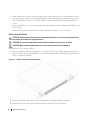 10
10
-
 11
11
-
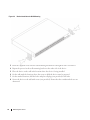 12
12
-
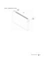 13
13
-
 14
14
-
 15
15
-
 16
16
-
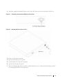 17
17
-
 18
18
-
 19
19
-
 20
20
-
 21
21
-
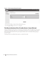 22
22
-
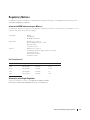 23
23
-
 24
24
-
 25
25
-
 26
26
-
 27
27
-
 28
28
-
 29
29
-
 30
30
-
 31
31
-
 32
32
-
 33
33
-
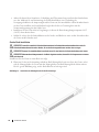 34
34
-
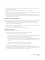 35
35
-
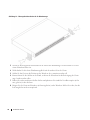 36
36
-
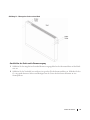 37
37
-
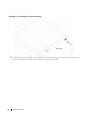 38
38
-
 39
39
-
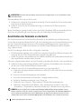 40
40
-
 41
41
-
 42
42
-
 43
43
-
 44
44
-
 45
45
-
 46
46
-
 47
47
-
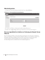 48
48
-
 49
49
-
 50
50
-
 51
51
-
 52
52
-
 53
53
-
 54
54
-
 55
55
-
 56
56
-
 57
57
-
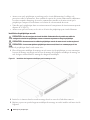 58
58
-
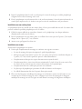 59
59
-
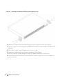 60
60
-
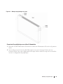 61
61
-
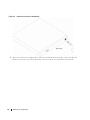 62
62
-
 63
63
-
 64
64
-
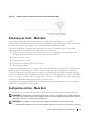 65
65
-
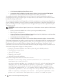 66
66
-
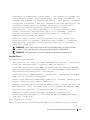 67
67
-
 68
68
-
 69
69
-
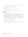 70
70
-
 71
71
-
 72
72
-
 73
73
-
 74
74
-
 75
75
-
 76
76
-
 77
77
-
 78
78
-
 79
79
-
 80
80
-
 81
81
-
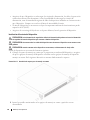 82
82
-
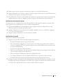 83
83
-
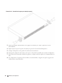 84
84
-
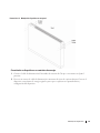 85
85
-
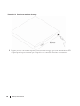 86
86
-
 87
87
-
 88
88
-
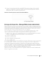 89
89
-
 90
90
-
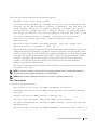 91
91
-
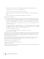 92
92
-
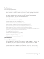 93
93
-
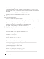 94
94
-
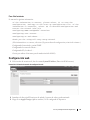 95
95
-
 96
96
-
 97
97
-
 98
98
-
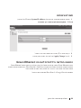 99
99
-
 100
100
-
 101
101
-
 102
102
-
 103
103
-
 104
104
-
 105
105
-
 106
106
-
 107
107
-
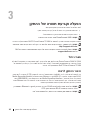 108
108
-
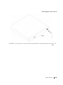 109
109
-
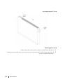 110
110
-
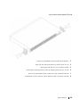 111
111
-
 112
112
-
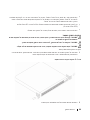 113
113
-
 114
114
-
 115
115
-
 116
116
-
 117
117
-
 118
118
-
 119
119
-
 120
120
-
 121
121
-
 122
122
-
 123
123
-
 124
124
-
 125
125
-
 126
126
-
 127
127
-
 128
128
-
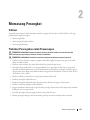 129
129
-
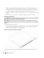 130
130
-
 131
131
-
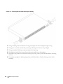 132
132
-
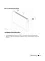 133
133
-
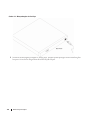 134
134
-
 135
135
-
 136
136
-
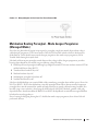 137
137
-
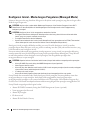 138
138
-
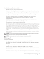 139
139
-
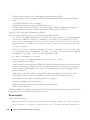 140
140
-
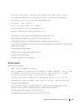 141
141
-
 142
142
-
 143
143
-
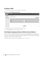 144
144
-
 145
145
-
 146
146
-
 147
147
-
 148
148
-
 149
149
-
 150
150
-
 151
151
-
 152
152
-
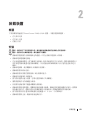 153
153
-
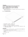 154
154
-
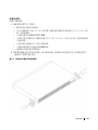 155
155
-
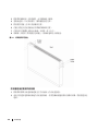 156
156
-
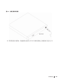 157
157
-
 158
158
-
 159
159
-
 160
160
-
 161
161
-
 162
162
-
 163
163
-
 164
164
-
 165
165
-
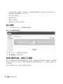 166
166
-
 167
167
-
 168
168
-
 169
169
-
 170
170
-
 171
171
-
 172
172
-
 173
173
-
 174
174
-
 175
175
-
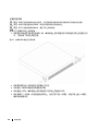 176
176
-
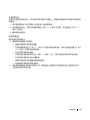 177
177
-
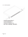 178
178
-
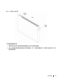 179
179
-
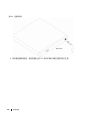 180
180
-
 181
181
-
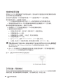 182
182
-
 183
183
-
 184
184
-
 185
185
-
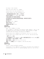 186
186
-
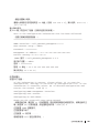 187
187
-
 188
188
-
 189
189
-
 190
190
-
 191
191
-
 192
192
-
 193
193
-
 194
194
-
 195
195
-
 196
196
-
 197
197
-
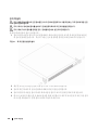 198
198
-
 199
199
-
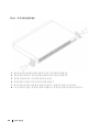 200
200
-
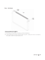 201
201
-
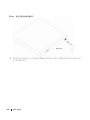 202
202
-
 203
203
-
 204
204
-
 205
205
-
 206
206
-
 207
207
-
 208
208
-
 209
209
-
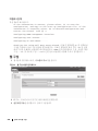 210
210
-
 211
211
-
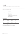 212
212
-
 213
213
-
 214
214
-
 215
215
-
 216
216
-
 217
217
-
 218
218
-
 219
219
-
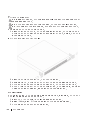 220
220
-
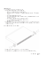 221
221
-
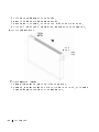 222
222
-
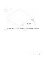 223
223
-
 224
224
-
 225
225
-
 226
226
-
 227
227
-
 228
228
-
 229
229
-
 230
230
-
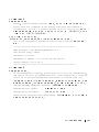 231
231
-
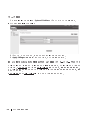 232
232
-
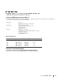 233
233
-
 234
234
-
 235
235
-
 236
236
-
 237
237
-
 238
238
-
 239
239
-
 240
240
-
 241
241
-
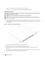 242
242
-
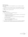 243
243
-
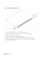 244
244
-
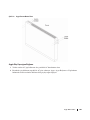 245
245
-
 246
246
-
 247
247
-
 248
248
-
 249
249
-
 250
250
-
 251
251
-
 252
252
-
 253
253
-
 254
254
-
 255
255
-
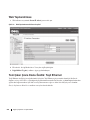 256
256
-
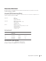 257
257
-
 258
258
-
 259
259
-
 260
260


