Yamaha PM4000 Manual de usuario
- Categoría
- Mezcladores de audio
- Tipo
- Manual de usuario

PROFESSIONAL AUDIO MIXING CONSOLE
PM4000
OPERATING MANUAL
YAMAHA

PM4000
OPERATING MANUAL

IMPORTANT NOTICE FOR THE UNITED KINGDOM
Connecting the Plug and Cord
WARNING : THIS APPARATUS MUST BE EARTHED
IMPORTANT. The wires in this mains lead are coloured in accordance with the following code:
GREEN-AND-YELLOW
:
EARTH
BLUE
:
NEUTRAL
BROWN
:
LIVE
As the colours of the wires in the mains lead of this apparatus may not correspond with the
coloured markings identifying the terminals in your plug proceed as follows:
The wire which is coloured GREEN-AND-YELLOW must be connected to the terminal in the
plug which is marked by the letter E or by the safety earth symbol or coloured GREEN or
GREEN-AND-YELLOW.
The wire which is coloured BLUE must be connected to the terminal which is marked with the
letter N or coloured BLACK.
The wire which is coloured BROWN must be connected to the terminal which is marked with the
letter L or coloured RED.
* This applies only to products distributed by YAMAHA - KEMBLE MUSIC (U.K.) LTD.
Professional audio mixing console Typ : PM4000
82/499/EWG
YAMAHA Europa GmbH
This product complies with the radio frequency
interference requirements of the Council Direc-
tive 82/499/EEC and/or 87/308/EEC.
YAMAHA CORPORATION
MICROPHONE CABLES AND MICRO-
PHONES CONNECTION
TO PREVENT HAZARD OR DAMAGE,
ENSURE THAT ONLY MICROPHONE
CABLES AND MICROPHONES DESIGNED
TO THE IEC268-15A STANDARD ARE
CONNECTED.

How to Use This Manual
If you are an engineer or technician who is familiar
with sound system design, much of this manual will
serve as a review for you. The basic features are
presented in the “BRIEF OPERATING INSTRUC-
TIONS” section. Check this and the “SPECIFICA-
TIONS” section, and you will see most of what you
need to know. The balance of this manual provides
background information for better utilization of the
console and auxiliary equipment.
If you would like to know more about AC power
distribution and safety, grounding, balanced versus
unbalanced cables, direct boxes, and so forth, this
information is also presented. Check the TABLE OF
CONTENTS.
There are internal preset switches within the
console which can be configured to change the func-
tions and/or signal paths in certain circuits. Refer to
the OPTIONAL FUNCTIONS section for details.
Terminology and
Typographic Conventions
Generally, where we refer to a particular control or
function as it is actually labeled on the console, we
will use all upper case type. That is, if we refer to an
input channel’s gain control, we may print “the input
GAIN control.” On the other hand, if the feature is not
labeled, we will use upper case type only on the first
letter; for example, “observe there is no identification
of the input Fader.” If the front panel label is incom-
plete or ambiguous, we may augment it. For example,
the input channel pushbutton switches labeled “1, 2,
3, 4, 5, 6, 7, 8” may be accompanied by the parenthetic
reference “(group bus assign)“.
Warning: To prevent fire or shock
hazard, do not expose this appliance
to rain or moisture.
There are eight groups (or subgroups, depending
on your linguistic preference). The group faders are
known as “Group Master Faders”. Their function is to
control the level on the eight “Group Mixing Busses.
The eight group busses are different and distinct from
the eight “Auxiliary Mixing Busses. The Stereo Fader
is actually a pair of closely spaced faders (L and R);
when we refer to the general function, we use the
term “Stereo Fader,” but if the availability of separate
left and right control is important, we may use the
plural “Stereo Faders.”
Particularly important information is distin-
guished in this manual by the following notations:
NOTE: A NOTE provides key information to
make procedures or functions clearer or easier.
CAUTION: A CAUTION indicates
special procedures or guidelines
that must be observed to avoid dam-
age to the console or related equip-
ment, or to avoid an undesirable
result while using the console.
WARNING: A WARNING indicates
special procedures or guidelines
that must be observed to avoid in-
jury to the operator or others using
or exposed to the console or related
equipment.
In the BRIEF OPERATING INSTRUCTIONS
section of this manual, each feature is provided with a
numerical reference. Elsewhere, if we are referring to
that feature, we may cite the reference number in
square brackets for clarity. For example, on the input
module, the fourth control to be described is the PAN
pot. In other places on the console there are other
PAN pots. For clarity, then, if we are discussing this
particular input PAN pot, we will describe it like this:
"the PAN pot [2]". Now, here’s a real warning that
Underwriters Laboratories says we have to print:
Page A-1

Table of Contents
Page Sect. Title
Section 1. Introduction
Section 2. Brief Operating Instructions
2-1
2.1
PM4000 Front Panel Features
2-1
2.1.1 The Standard Monaural Input Module
2-7
2.1.2 The Stereo Input Module
2-12
2.1.3 The Master Module (1 - 8)
2-17
2.1.4 The Stereo Master Module
2-19
2.1.5 The TB (Talkback) Module
2-22
2.1.6 The Monitor Module
2-25
2.1.7 The Meter Bridge
2-27
2.2
PM4000 Rear Panel Features
2-34 2.4
The PW4000 Power Supply
Section 3. Specifications
3-1
PM4000 Mixing Console General Specifications
3-2
PW4000 Power Supply Specifications
3-3
PM4000 Input Characteristics
3-3
PM4000 Output Characteristics
3-4
Dimensional Drawings
3-7
Block Diagrams
Section 4. Installation Notes
4-1
4.1
Planning An Installation
4-1
4.2
Power Mains
4-1
4.2.1 Verify The Correct Mains Voltage
4-1
4.2.2 Ensure There is a Good Earth Ground
4-2
4.2.3 How To Obtain a Safety Ground When
Using a 2-wire Outlet
4-3
4.2.4 Improperly Wired AC Outlets: Lifted
Grounds
4-3
4.2.5 Improperly Wired AC Outlets: Lifted
Neutral
4-4
4.2.6 AC Safety Tips
4-4
4.2.7 Power Source Integrity
4-4
4.2.8 Turn-On Sequencing
4-5
4.3 Theory of Grounding
4-5
4.3.1 Why Is Proper Grounding Important?
4-6
4.3.2 Ground Loops
4-7
4.3.3 Basic Grounding Techniques
4-8
4.3.4 Balanced Lines and Ground Lift Switches
4-9
4.4
Audio Connectors and Cables
4-10
4.4.1 Types of Cable To Use
4-10
4.4.2 Cable Layout
4-10
4.4.3 Balanced versus Unbalanced Wiring
4-13
4.4.4 The Pro’s And Con’s of Input Transformers
4-14
4.4.5 Noise And Losses In Low and High
Impedance Lines
4-15 4.5 Direct Boxes
Page Sect. Title
4-15
4.5.1 Passive Guitar Direct Box
4-17
4.5.2 Active Guitar Direct Box
4-17 4.6 Configuring Equipment Racks
Section 5. Gain Structure and Levels
5-1
5.1 Standard Operating Levels
5-2
5.2 Dynamic Range and Headroom
5-2
5.2.1 What Is Dynamic Range?
5-2
5.2.2 The Relationship Between Sound Levels and
Signal Levels
5-2
5.2.3 A Discussion Of Headroom
5-2
5.2.4 What Happens When The Program Source
Has Wider Dynamics Than The Sound
Equipment?
5-4
5.2.5 A General Approach To Setting Levels In a
Sound System
5-4
5.2.6 How To Select a Headroom Value and
Adjust Levels Accordingly
5-6
5.3 Gain Overlap And Headroom
Section 6. Optional Functions
6-2
6.1 Removing and Installing A Module
6-3
6.2 Mono Input Direct Out Jack:
Pre-Fader or Post-Fader (switch)
Pre-ON or Post-ON Switch (jumper)
6-4
6.3 Mono Input Aux Sends: Pre Fader & EQ or
Pre Fader/post EQ
6-5 6.4
Mono Input Cue/Solo Switch: Pre-Fader or
Follow MT PRE Switch
6-6
6.5
Stereo Input Cue/Solo Switch: Pre-Fader or
Follow MT PRE Switch
6-7
6.6
Mono & Stereo Input Channel MT PRE
Switch: Pre- or Post-ON Switch
6-8
6.7
Stereo Input Channel Insert In/Out Jacks:
Pre-EQ or Post-EQ
6-9
6.8 Stereo Input Channel Aux Sends:
Pre Fader & EQ or Pre Fader/Post EQ
6-10 6.9
Stereo Input Channel Aux Sends 1-8:
L+R Blend or Stereo Pairs
6-11 Stereo Input Channel Stereo
6.10
Aux Sends 1 & 2: L+R Blend or Stereo Pairs
6-12 6.11 Stereo Input Channel Feed to Monitor
Module ST IN 3 or ST IN 4
6-13 6.12 Phase Switch Function: Change Polarity of
Both L and R inputs, or of L Only
6-14 6.13 Stereo Input Module: Output Enable
Jumpers to Group, Stereo and Aux Busses
6-15 6.14 Master Module: Group-to-Matrix Assigned
Pre or Post Group Master Fader
Page TC-1

Page Sect. Title
6-16
6.15 Stereo Master to Matrix ST Bus: Pre or Post
ST Master Fader
6-17
6.16 Installation of Optional Input Transformers
6-18
6.15 Hints on Circuitry For Remote Control of
the VCA Masters and Mute Groups
Section 7. Operating Notes and Hints
7-1 7.1 Console Gain Structure
7-l 7.1.1 What Is The Proper Gain Structure?
7-1
7.1.2 What Affects Gain Structure?
7-1
7.1.3 Establishing The Correct Input Channel
Settings
7-2
7.1.4 Establishing The Correct Group Master
Settings
7-2
7.1.5 Establishing The Correct Aux Send Master
Settings
7-2
7.1.6 Establishing The Correct Mix Matrix
Settings
7-3
7.1.7 Establishing The Correct Aux Return
Settings
7-3
7.1.8 How VCA Control Affects Gain Structure
7-4
7.1.9 Channel Muting and Gain Structure
7-4
7.2 Further Hints & Conceptual Notes
7-4
7.2.1 What Is a VCA, and Why Is It Used?
7-4
7.2.2 The Distinction Between The Group Busses
and The VCA Master “Groups”
7-7
7.2.3 Using The Channel Insert In Jack as a
Line Input
7-7
7.2.4 Understanding and Using The Mix Matrix
7-9
7.2.4.1
The Mix Matrix In General Sound
Reinforcement
7-9 7.2.4.2
Using The Matrix Sub Inputs
For Effects
7-9
7.2.4.3
Other Uses For The Matrix
Sub Inputs
7-10 7.2.4.4 Use of the Matrix to
Pre-Mix Scenes
7-10
7.2.5 Understanding and Use of The Master Mute
Function
7-12
7.2.6 Stereo Panning To the Eight Group Mixing
Busses
Page Sect. Title
Section 8. Applications
8-1
8-1
8-1
8-2
8-2
8-3
8-3
8-3
8-4
8-4
8-6
8-7
8.l General
8.1.1 Theatre
8.1.2 Production
8.1.3 Post Production
8.1.4 Video
8.1.5 Sound Reinforcement
8.2 Setup Concepts
8.2.1 Deriving A Stereo Mix From Groups 1 - 8
8.2.2 The Mix Matrix Allows the 8 Groups Plus
the Stereo Bus to Function as 10 Subgroups
8.2.3 How To Get 5 Independent Stereo Mixes or
10 Mono Mixes by Using the Stereo Bus
Plus the Mix Matrix
8.2.4 How to Use the VCA Masters Plus the
Group Master Faders to Obtain the
Functional Equivalent of 16 Subgroups
8.2.5 Using More Than One VCA Master to
Control the Same Input Channels In Order
To Handle Overlapping Scenes
Section 9. Maintenance
9-l
9-1
9-1
9-1
9-1
9-2
9-2
9-3
9.1
Cleaning The Console
9.1.1 The Console and Power Supply Exterior
9.1.2 Power Supply Air Filters
9.1.3 Pots And Faders
9.1.4 The Console Interior
9.2
Meter Lamp Replacement
9.3
Where To Check If There Is No Output
9.4
What To Do In Case of Trouble
Page TC-2

Section 1
Introduction

Section 1.
Introduction
The PM4000 is a professional audio mixing console
with the kind of flexibility, performance and reliability
for which Yamaha has earned a worldwide reputation.
It picks up where the famous PM3000 left off, with still
more functions, a higher level of performance, and a
greater degree of versatility than ever before. The
console now comes with both mono and stereo input
modules, and you can determine the complement of
each type of module in your unit at the time you order
it, or you can later swap modules in the field (between
shows if need be).
The console is available with 24, 32, 40 or 48 input
positions (24 channel versions are available in the
U.S.A. only on special order). However, if fully config-
ured with stereo input modules, the actual number of
input
sources
is
substantially higher (the mix of mono
and stereo modules can add up to no more than 64 in-
put channels per mainframe, as limited by power
supply capacity). There are eight VCA (Voltage Con-
trolled Amplifier) Master Faders which can be assigned
to control any combination of input channels (see
Section 7 for a discussion of VCAs). In addition, there
are eight group mixing busses, as well as a stereo
mixing bus, to which any of the input channels can be-
assigned. There are also eight monaural auxiliary
mixing busses and two pair of stereo auxiliary mixing
busses to which each input channel may be assigned by
means of sealed PRE/OFF/POST switches and Send
Level controls. The stereo aux busses may be switched
to dual mono busses, for a total of twelve busses that
can be used to augment the eight groups plus the stereo
bus for a total of 22 audio mixing busses, or they may be
used for a combination of foldback send (stage monitor),
effects send and remote mixes.
Input channel signals may be assigned directly to the
stereo bus, or assignment can be made via the Group
Masters. Thus, the console can function in a sub-
grouped mode with a stereo "grand master" fader, or it
can function with independent stereo and multi-channel
output mixes.
The PM4000 inputs are differentially balanced, and
are equipped with a 30 dB attenuation PAD plus a
continuously variable 50 dB range GAIN trim control so
that literally any mic or line level signal can be accom-
modated with channel faders set at nominal level.
Optional input transformers may be installed internally
on a channel-by-channel basis when extra grounding
isolation is required. While the console has ample
headroom throughout, it is always possible to incor-
rectly set controls. For this reason, the PM4000 is
equipped with level detection at several stages. Input
LED meters and "PEAK" LEDs are provided. The latter
not only monitor the input preamp level, they check for
overboost in the EQ section. too. Metering can be front-
panel switched to pre or post fader (actually, pre/post
VCA). Finally, if the mixed levels on the group, auxil-
iary, stereo, matrix or cue busses adds up to be too high,
a “PEAK” LED in the output meters will flash on to
warn of the impending danger of clipping.
Naturally, the PM4000 is equipped with a Mix
Matrix, the feature Yamaha pioneered in professional
audio consoles. The PM4000 Mix Matrix is an 11x8
configuration. That is, there are 11 possible sources that
can be mixed together into one output. Those 11 sources
can be mixed together eight different ways on eight
different modules. Each matrix channel accepts a direct
sub input from a rear panel connector, plus signals from
the stereo bus (L&R) and the eight subgroups (pre or
post master fader, depending on internal preset
switches). These 11 sources all go through a MATRIX
MASTER control and an on/off switch to a discrete rear
panel output. The matrix can save a tremendous
amount of time and effort when you want to set up
stage monitor mixes from the subgroups, when you
want to create different speaker mixes for different
zones of the house, to feed local and remote programs
simultaneously, to make mono and stereo mixes from
the same subgroups, and so on. In fact, if the matrix is
set to pick up the subgroups ahead of the Group Master
Faders, then the subgroups can be mixed onto the
stereo bus with one mix, and completely independent
mono or stereo mixes can be achieved from the same
subgroups via the matrix.
The PM4000 has a VCA grouping system which is
separate from the audio grouping. Eight "VCA GROUP"
switches next to each channel fader enable that channel
to be assigned so it is controlled by one or more of the
VCA Master Faders. When multiple input channels are
assigned to a given VCA bus, those channels output
levels can be raised or lowered by the single VCA
Master Fader. Consider how this differs from the
conventional groups. When multiple input channels are
assigned to one of the eight group (audio) mixing
busses, those channels’ combined signals can be raised
or lowered in level with the Group Master Fader. The
audio result is the same as though the VCA Masters
were used... with one exception; if signal processing of
multiple inputs is required, it is necessary to run that
Page 1-1

combined signal through a single bus, which is why full-length
Group Master Faders are provided on the PM4000. However,
when the VCA Master Faders are used, more than one VCA
Master can combine to alter the level of a single input channel.
What’s more, the VCA Master Fader, because it affects the input
channel directly, can also alter that channel’s post-Fader output
to any of the eight auxiliary mixing busses, something not
possible with the conventional Group Master Faders. Because
the VCA Master levels are voltage controlled, the PM4000 can be
automated, at least to the extent of controlling group levels. A
rear panel multi-pin connector can be used for this purpose.
These VCAs are sonically improved, and to insure reliable
operation, all bus, VCA group, and mute group assignments are
via proven latching switches; Yamaha has avoided C-MOS
switching and “glue-logic” for these vital functions.
The MASTER MUTE function facilitates scene changes and
complex cues. Each input channel has eight MUTE assign
switches. These permit the channel’s on/off function to be re-
motely controlled by the eight MASTER MUTE switches. Once a
channel is switched on locally, it can be muted (turned off) or
unmuted (turned on) if it is assigned to one or more of the mute
groups. This permits multiple channels to be silenced or acti-
vated all at once, which expedites live sound mixing, band
personnel or instrument changes, theatrical scene changes, and
so forth. If, however, it is imperative that a certain channel never
be inadvertently muted, or that muting temporarily be overrid-
den, the input channel’s MUTE SAFE switch can be engaged.
Muting can also be controlled remotely, via a rear panel connec-
tor, so automation here, too, is possible. In addition to the master
muting function, the VCA master faders have mute switches
which mute the corresponding VCA group (or at least prevent the
master from altering input levels); this provides another, differ-
ent layer of master control of levels to facilitate tracking program
changes with the mix.
In recognition of the increasing trend toward full-function
auxiliary return, the PM4000 relies upon full-capability input
modules for aux returns. That's why the console is available with
up to 48 input channels, including stereo inputs. For added
flexibility, the INSERT in jack(s) on any input module can be
used for aux return purposes, and then the channels INSERT
ON switch can pick up the aux return instead of any signal
which may remain connected to the main channel input(s). This
allows a given channel to perform different functions at different
times without patching cables.
An excellent feature of the PM4000 is its extensive cue and
solo capability. There is a CUE/SOLO switch on every input
channel and on the aux returns, and a CUE switch on every
auxiliary send, the group outputs, the matrix outputs and the
Figure 1-1. PM4000 Modules (Left-to-Right):
Monaural Input (24, 32, 40 or 48 in console), Stereo
Input (at least 4 per console), Master, Stereo Master,
Talkback, and Monitor
Page 1-2

stereo master output. Cue replaces the signal in the
headphones and the stereo cue XLR outputs with only
those sources whose CUE switches are engaged.
The CUE system has input priority so that the
operator may normally monitor the cue signal from the
stereo bus or the group busses, and can instantly check
one or more channel or aux return inputs without
having to first release the bus CUE switches. This
capability is great for troubleshooting, previewing a
channel before applying it to the mix, or “touching up”
the EQ on a channel during a performance. For use
ahead of a live show, the console may be placed in solo
mode. In this mode, only the input channel(s) whose
CUE/SOLO switch is engaged will feed the console’s
outputs, and all other input channels will be muted. If
the stereo input modules are used for returns, recessed
switches in these modules can be set so returns will not
be muted and any effects applicable to the soloed input
will be heard. Annunciator lights signal the operator
whether the console is in solo or cue mode, and whether
any CUE or CUE/SOLO switch is engaged. Two head-
phone jacks enable a pair of console operators (or an
engineer and producer) to work side-by side on complex
projects.
The PM4000 has an excellent talkback system plus
a useful test oscillator. An XLR input (with phantom
power) can be set to accept any microphone or line level
input, and is activated with the TALKBACK switch.
That signal can be slated to any of the eight group
mixing busses, the eight aux send mixing busses, the
two stereo aux busses, the stereo mixing bus, and to a
rear panel XLR TB output. The test oscillator can be set
to 100 Hz, 1 kHz or 10 kHz fixed frequencies, or can be
swept from 0.2 to 2x the set frequency, and its output
level is adjustable. Pink noise may be selected, too. The
oscillator can be slated to the same busses as the
talkback, and also has its own rear panel output connec-
tor so the signal can be routed to other equipment or
other console inputs for testing.
Extensive metering is provided with a total of 14 VU
meters on the 24 and 32 channel versions, or 18 VU
meters on the 40 and 48 channel versions (each with a
peak LED). Several of these meters can be switched to
monitor alternate busses, so the metering gives you a
comprehensive view of signal levels in your system.
PM4000 electronic performance is everything you’d
expect from the people who developed the PM3000. It is
even more advanced, with lower noise levels than ever.
Wide headroom throughout, exceptionally low distor-
tion, and quiet controls are the hallmark of this top
quality mixing console. The specifications are honest
and conservative. The performance is audibly superb.
Physically, the PM4000 is as appealing as it is
electronically. An all new chassis design with aircraft-
style bracing offers increased strength to sustain
repeated trips on the road. A gray finish and subtly
color coded controls set the backdrop for the PM4000’s
hundreds of illuminated switches and indicators.
Multiple rear-mounted cooling fans reduce internal
temperatures to prolong component life.*
The highly advanced PM4000, with its many inter-
nally switchable functions, is as close to a custom
console as you can get... while retaining all the value
and reliability of an off-the-shelf Yamaha console. While
its numerous internal and front panel functions may at
first intimidate the casual console operator, the PM4000
is actually a very straightforward console to use.
Anyone who has used the PM3000, or even a PM2000,
should immediately feel comfortable with the PM4000.
Take a while to study the panel, read the descriptions in
this manual, and you’ll find operating this console is
very natural... and satisfying because you can make it
do the job the way you need it done.
*Heat is generated by electronic components, and is the
enemy of them. In some segments of the. industry (such
as Las Vegas showrooms), it has been customary to leave
equipment switched on 24 hours. This tradition grew out
of the days when vacuum tube equipment was prevalent,
and vacuum tubes did last longer
if they remained on
rather than being switched. Solid state devices used in
modern mixing consoles are less susceptible to damage
from switching, but the heat build up sustained in
continuous 24 hour operation will shorten component
life. Therefore, it’s a good idea to turn off your equipment
when it is not in use (unless you are in a very humid
environment where the heat
of operation wards off
corrosion-causing, short-circuit-promoting moisture
condensation). While the PM4000 remains cooler than
its predecessors, thanks to cooling
fans, it remains a
prudent practice to shut it off when it is not being used.
Figure 1-2. PM4000-48 Rear Panel
Page 1-3

Section 2
Brief Operating Instruction

This locking switch assigns the channel output
directly to the stereo bus. An LED in the switch
turns on when the signal is assigned to the stereo
bus. If you want the cleanest, quietest stereo mix,
create it by assigning inputs directly to the stereo
bus with this switch rather than running signal
to group busses and then mixing the groups down
to stereo.
1. 1 2 3 4 5 6 7 8 (ASSIGN switches)
These locking switches assign the channel output
to group mixing busses 1 through 8. An LED
indicator in each switch turns on when the signal
is assigned to the bus.
2. PAN (switch & rotary control)
The locking PAN switch activates the PAN pot so
you can use it to position signal between any odd-
numbered and even-numbered group mixing
busses (provided the corresponding ASSIGN
switches are engaged). This lets you create up to
four additional stereo mixes. An LED in the
switch turns on when the PAN switch is engaged.
Center position applies 3 dB less signal to each
bus than the level obtained with full left or right
assignment so that the combined stereo signal
across a given pair of busses adds up to constant
power at all PAN pot positions.
3. ST (Stereo)
Figure 2-1a. PM4000 Standard Input
Module (upper portion of module)
Section 2.
Brief Operating Instructions
2.1 PM4000 Front Panel
Features
NOTE: Features are numbered to correspond with the
numbers on these module drawings. In the case of the
input modules, where the standard monaural module
and stereo modules are similar, we have used the same
feature number where the features are identical. Where
the features are not identical, we have used an “S” suffix.
For example, feature [4] is the 48V phantom power
switch in both the monaural and the stereo input
modules, but the PAN switch and pot [2] on the stan-
dard input module is not the same as the BAL/PAN
switch, and the concentric selector switch and pot [2S]
on the stereo input module.
2.1.1
The Standard Monaural Input Module
4. +48V
This switch turns phantom power on and off at
the channel’s XLR input connector. Power can be
turned on, however, only if the MASTER PHAN-
Page 2-1

TOM POWER switch is on. An LED in the switch
turns on when phantom power is being applied to
the channel input connector.
When both the Master and this switch are on,
+48 volts is applied to both pins 2 & 3 of the
channel input XLR connector for remote power-
ing of condenser microphones. Although phantom
power will not harm most dynamic and other
non-phantom powered microphones or line-level
devices, connection of an unbalanced source to
the channel input could partially short the
console’s phantom supply, cause undue loading,
and induce hum. Therefore, it is a good practice
to turn off the channel’s phantom power unless it
is actually in use.
NOTE: The console's microphone power supply is not
intended for A-B powered microphones. External sup-
plies may be used with these devices, in which case the
console’s phantom power should be turned OFF on the
appropriate channels. The optional input transformers,
if installed, do not affect phantom power operation.
5. GAIN
This rotary knob provides 50 dB of continuously
variable adjustment for the input preamplifier
gain. A setting of -70 (full clockwise rotation)
provides maximum gain for low-level mic inputs,
whereas a setting of -20 provides minimum gain
for low-level line inputs or “hot” mics. These
settings provide 30 dB less overall gain when 30
dB pad is engaged [6].
6. 30 dB (pad switch)
Engaging this pushbutton switch attenuates the
signal 30 dB and turns on an LED in the switch.
The PAD should be used in conjunction with the
GAIN control to obtain the precise channel
sensitivity necessary for a given source. If you’re
not sure whether an input is high line level or
mic level, begin with the pad engaged, and the
GAIN control at -20 (+10) position. Then rotate
the GAIN control clockwise. If you still don’t get
enough level, or if the signal is noisy with a lot of
gain, then turn down the GAIN, disengage the
pad and reset the GAIN control as necessary.
NOTE: By adjusting the GAIN control, you may be able
to get the same overall level with or without the pad
engaged. Listen for noise and distortion, though; if the
signal is noisy, don’t use the pad. If there is a lot of
distortion, use the pad.
Front
Bandwidth
panel
Q
(octave)
3.0
0.5
1.4
1.0
center position
1.2
1.2
0.7
2.0
0.5
2.5
7. PEAK
This red LED turns on to indicate when the
signal present after the channel preamp is too
high in level. The LED triggers 3 dB below
clipping, and should therefore flash on only
occasionally.
This indicator measures signal from the XLR or
from the INSERT IN jack, whichever is active, as
well as after the equalizer. If necessary, use the
PAD or decrease the GAIN setting to prevent the
LED from remaining on any longer than momen-
tarily; otherwise excessive distortion and insuffi-
cient fader travel will result.
8. Ø (Phase)
This switch reverses the polarity of pins 2 and 3
of the channel’s XLR input connector. In normal
position (switch button up), pin 2 is the signal
high conductor, and in reverse position (switch
engaged), pin 3 is high. An LED in the switch is
illuminated when polarity is reversed.
This eliminates the need to rewire connectors or
use adapters for out-of-phase (reversed polarity)
audio sources. Sometimes intentional polarity
reversal can be helpful in canceling leakage from
adjacent microphones, or in creating electro-
acoustic special effects by mixing together out-of-
phase signals from mics picking up the same
sound source.
EQUALIZER
The input channel equalizer is divided into four
bands, each with sweepable filter frequencies.
The high and low bands may be switched for a
peaking or shelving type curve, whereas the high-
mid and low-mid bands are of the peaking type.
All four bands have adjustable Q, providing fully
parametric type EQ. The level (gain) is adjustable
over a range of 15 dB boost and 15 dB cut in each
band.
9. HIGH (Peak/Shelf)
This locking switch selects peaking type EQ
(switch out) or shelving type EQ (switch en-
gaged). When the switch is engaged (shelving
mode), the adjacent Q control is not operational.
Q
This rotary control adjusts the Q (the bandwidth)
of this section of the equalizer from a very narrow
band to a very broad band, with a center detent
at a Q of 1.2.
Page 2-2
Channel EQ “Q” Characteristics

1 ~ 20 kHz
The outer concentric knob sweeps the EQ Fre-
quency between 1,000 and 20,000 Hz.
-15 ~ +15 dB
The inner concentric knob adjusts the gain of the
set frequency band by plus or minus 15 dB. A
center detent is provided for unity gain.
10. HIGH-MID
Q
This rotary control adjusts the Q (the bandwidth)
of this section of the equalizer from a very narrow
band to a very broad band, with a center detent
at a Q of 1.2.
0.4 ~ 8 kHz
The outer concentric knob sweeps the EQ Fre-
quency between 400 Hz and 8,000 Hz.
-15 ~ +15 dB
The inner concentric knob adjusts the gain of the
set frequency band by plus or minus 15 dB. A
center detent is provided for unity gain.
11. LO-MID
Q
13. EQ (In/Out switch)
This locking switch activates the channel EQ or
bypasses it completely. The EQ is active when the
switch is engaged (and the LED in it is on). Bypass
allows for A-B comparison, and absolutely mini-
mum signal degradation when EQ is not needed.
14.
HPF (H.P. filter in/out switch and control)
This locking switch activates the input channel
HIGH PASS FILTER or bypasses it. The filter is
active when the switch is engaged (and the LED in
it is on). This filter bypass function is independent
of the EQ section, which has its own bypass switch.
20 ~ 400Hz
This rotary control adjusts the Q (the bandwidth)
of this section of the equalizer from a very narrow
band to a very broad band, with a center detent
at a Q of 1.2.
80 Hz ~ 1.6kHz
The outer concentric knob sweeps the EQ Fre-
quency between 80 Hz and 1,600 Hz.
-15 ~ +15 dB
The inner concentric knob adjusts the gain of the
set frequency band by plus or minus 15 dB. A
center detent is provided for unity gain.
12. LO (Peak/Shelf)
This locking switch selects peaking type EQ
(switch out) or shelving type EQ (switch en-
gaged). When the switch is engaged (shelving
mode), the adjacent Q control is not operational.
Q
This rotary control sweeps the cutoff frequency of a
high pass filter (or "low cut" filter) from 20 Hz to
400
Hz. The filter slope is 12 dB per octave.
Typical applications including cutting wind noise,
vocal "P" pops, stage rumble, and low frequency
leakage from adjacent instruments. You can use
higher frequency settings to reduce leakage into
mics that are primarily handling high-frequency
sources. It is a good practice to use the filter to
protect woofers from unnecessary over-excursion
due to the presence of unneeded low frequency or
sub-sonic components, especially if a microphone is
dropped or kicked. Bypass the filter (switch up)
only when you want very low frequencies, as with
an organ, drum, bass guitar, and so forth.
15. INSERT PRE
The insert in point is normally after the HPF and
equalizer. Engaging this switch moves the insert
point between the equalizer (pre-EQ) and the
HPF. The LED in the switch is on when the
insert point is pre EQ.
16. INSERT ON
This rotary control adjusts the Q (the bandwidth)
of this section of the equalizer from a very narrow
band to a very broad band, with a center detent
at a Q of 1.2.
30 Hz ~ 600 Hz
The outer concentric knob sweeps the EQ Fre-
quency between 30 and 600 Hz.
-15 ~ +15 dB
The inner concentric knob adjusts the gain of the
set frequency band by plus or minus 15 dB. A
center detent is provided for unity gain.
This locking switch activates the channel’s
INSERT IN jack, from which it applies signal to
the rest of the channel (see item [15] also). The
INSERT OUT jack is always “live,” and this
switch does not affect it. The primary use of this
switch is to select or de-select any signal proces-
sor or independent line input source which may
be plugged into INSERT IN. When the switch is
engaged, making the Insert In jack “live,” the
LED in the stitch is on.
If there is nothing plugged into the INSERT IN
jack, this switch has no effect.
Page 2-3
NOTE: PM3000 users will notice there is no EQ CLIP
indicator. Clipping at this stage can occur even though
the input signal is not clipping, due to boost (gain)
applied with the EQ circuitry. In the PM4000, clipping
in the equalizer is detected and shown on the PEAK
indicator [7] adjacent to the GAIN control.

Figure 2-1b. PM4000 Standard Input Module
(middle portion of module)
NOTE: A signal processor (effects device) can be set up
before it is needed, its levels adjusted using the always
active INSERT OUT signal, and then the processor can
be inserted on cue in the channel’s signal path by
pressing this switch.
17. AUX 1 - 8 (Send level & Pre/Off/Post switches)
There are 8 rotary AUX send level controls with
concentric PRE/OFF/POST switches. The switch
mutes (turns off) the send, or derives signal
before (PRE) or after (POST) the channel fader
and equalizer. The inner rotary control deter-
mines how much of the selected signal source is
applied to the correspondingly numbered auxil-
Page 2-4
iary mixing bus. When the switch is in the center
(OFF) position, no signal is applied to the auxil-
iary bus.
NOTE: In some applications, it is preferable to have the
PRE position be Pre-Fader & Post-EQ rather than Pre-
Fader & Pre EQ. The PM4000 is equipped with internal
switches that make it easy to change the “Pre” of each
AUX send in this manner. This functional modification
can be performed on a channel-by-channel basis, and for
any or all AUX sends within each channel. Refer to the
OPTIONAL FUNCTIONS section of this manual for
additional information.
NOTE: All eight aux sends perform identical functions,
as shipped. Color coding helps associate the channel
send controls with the Aux Master LEVEL controls. If
you reset the “Pre” function for the sends of some busses,
or on some channels, it is a good idea to attach a note to
the console indicating how you have set it up.
CAUTION: Any input module may be used
as an auxiliary return. If a module is used
in this way, DO NOT assign the return to
the same auxiliary bus whose output is
feeding the signal processor which is
providing the return signal. This will
almost certainly cause feedback which
can damage circuits and/or loudspeakers.
This caution applies to Aux busses 1
through 8, and to the stereo aux busses.
18. AUX ST 1
These are two pair of concentric level controls
and switches. Depending on how you set the
outer switch on the right-hand control, they can
function as either an independent pair of Aux
sends, similar to the eight individual AUX sends,
or they can function as a single stereo Aux send
with level and balance controls.
The outer PRE/OFF/POST switch on the left-
hand control set determines whether the send
is off, derives signal before the fader and
equalizer, of after them (just as with the
individual aux sends). This function affects
both “sides” of the AUX ST 1 output, whether
used for stereo or dual mono sends.
The outer switch on the right-hand control set
determines whether AUX ST 1 functions as a
stereo send (switch set to the left “PAN” posi-
tion) or as a pair of mono sends (switch set to
the right “LEVEL R” position).
When the send is set for stereo mode, the inner
rotary control on the left determines the overall
LEVEL applied to the Stereo 1 L & R auxiliary

mixing buses, and the inner rotary control on
the right serves to PAN that signal between the
L & R sides of that stereo pair.
When the send is set for dual mono mode, the
inner rotary control on the left sets the LEVEL
applied to the AUX ST L bus (i.e., LEVEL-L),
and the inner rotary control on the right sets
the LEVEL applied to the AUX ST R bus (i.e.,
LEVEL-R).
19. AUX ST 2
These two pair of concentric controls and
switches function just like AUX ST 1, but affect
the #2 auxiliary stereo bus pair.
Note: By setting AUX ST 1 and AUX ST 2 to dual mono
mode, you have a total of 12 independent auxiliary
mixing busses.
20. MT PRE (switch) and level meter
The channel level meter consists of 6 LEDs that
display signal levels from
-20
dB u to +6 dBu,
plus PEAK (3 dB below clipping). The meter
normally indicates the level after the EQ and the
channel fader. Engaging the METER PRE switch
causes the meter to indicate level ahead of the
fader. An LED in the switch is illuminated when
the meter is displaying pre-fader level.
21. ON switch (Channel On)
Pressing this switch turns the input channel ON,
which means the channel output is potentially
available to the 8 group mixing busses, the stereo
bus, the 8 auxiliary mixing busses, and the two
pair of stereo aux mixing busses. Engaging the
switch does not necessarily mean the switch will
be illuminated or that the channel will turn on;
muting logic may be dictating that the channel
remain off. When the channel is OFF, the feed to
the VU meter is also off, although the signal may
still be previewed with the CUE/SOLO switch
[26].
Figure 2-1c. PM4000 Standard Input Module
(lower portion of module)
22. VCA GROUP (Assign 1 - 8)
Engaging any of these 8 locking switches enables
the corresponding VCA GROUP MASTER
FADER(s) to also control the output level of this
channel. When a VCA switch is engaged, the
LED in the switch turns on.
CAUTION: If you assign (or deassign) an
input channel to a VCA group during a
performance, the channel gain will jump
up or down unless the corresponding VCA
MASTER Fader is set precisely to the
nominal position (green LED "NOMINAL"
LED illuminated).
23. MUTE (Assign 1 - 8)
Engaging any of these 8 locking switches enables
the corresponding Group MUTE MASTER
switch(es) to “kill” (turn off’) this channel. An
exception exists when the channel MUTE SAFE
switch [24] is engaged, in which case these MUTE
switches can have no effect. When a MUTE switch
is engaged, the LED in the switch turns on.
24. S (Mute safe)
The LED in this locking switch is illuminated
when the switch is engaged. When MUTE SAFE
is on, it overrides any combination of MASTER
MUTE and channel MUTE switch settings, and
Page 2-5

prevents the channel from being muted. Engag-
ing this switch ensures the channel will always
be on so long as the channel ON switch is also
engaged.
25. FADER
This long-throw fader sets the level applied to the
8 group mixing busses, and the stereo bus. It also
affects any auxiliary feeds which are set to post-
fader position. The Fader does not pass audio, but
instead controls a VCA through which the audio
signal flows. The channel level may, therefore,
also be controlled remotely from the 8 VCA
Master Faders [47] or the VCA/MUTE CON-
TROL connector [129] if one or more of the VCA
GROUP Assign switches [22] is engaged.
26. CUE/SOLO
The function of this switch on each input channel
will depend on the setting of the console’s Master
SOLO MODE switch [48].
If the console is set to the SOLO MODE, then
pressing this switch mutes all other input chan-
nels, and only the input channel(s) whose CUE/
SOLO switch is engaged will feed the console
outputs. (This is also known as “solo in place.“)
If the console is set to the CUE MODE, the
console then has a dual-priority cue system,
designed to give the engineer maximum control
and speed when it is most important. In this
mode, pressing the channel CUE/SOLO switch
causes the channel signal to replace any master
signal in the Cue output and the Phones output.
The engineer can readily select any of 27 output
mixes (Group 1-8, Matrix 1-8, Aux Send 1-8, Aux
Stereo 1 and 2, or Stereo L & R) by pressing the
corresponding CUE switches. In most cases, once
the individual output mixes have been estab-
lished, the engineer will want to listen to the
“most important output mix” during the perfor-
mance, possibly the main house feed or the vocal
group. However, should feedback occur, or should
any other condition require attention, the
PM4000 enables the engineer to instantly check
any input channel or channels by pressing their
CUE/SOLO switch(es). The input whose CUE
switch is engaged then automatically replaces the
selected output mix in the headphone and cue
outputs. The engineer can make the necessary
adjustment, and then return to monitoring the
original output mix simply by releasing the input
CUE/SOLO switch.
Pressing the CUE/SOLO switch part-way down
causes momentary contact; pressing it further
locks it down. In either case, the LED in the
switch is illuminated when the channel is being
cue’d or soloed. Although the cue signal is not
affected by the Fader or ON/off switch, it is
affected by the Input PAD, GAIN control, Filter,
channel EQ, and anything connected between the
channel’s INSERT IN and OUT jacks (if the
INSERT switch is engaged).
NOTE: Since the console operator may normally be
listening to the stereo bus or one or more group busses by
means of engaging their cue switches, the PM4000 is set
up for input cue priority. As soon as one or more input
channel cue switches are engaged, any bus cue signal
will be replaced by the input cue signal(s). Input priority
is also given to other PM4000 inputs (Aux Return cue),
not just to the input channel cue signals.
Page 2-6

2.1.2. The Stereo Input Module
The PM4000 comes with at least four stereo input
modules, located in near the master section. More of
these stereo modules can be ordered in lieu of the
monaural input modules. Their position in the main-
frame is completely interchangeable with the standard
input modules (see Section 6 for details).
1S. 1 2 3 4 5 6 7 8 (ASSIGN switches)
These locking switches assign the channel output
to group mixing busses 1 through 8. The signal is
assigned as follows: the left input signal is routed
to the odd-numbered busses, and the right input
signal to the even-numbered busses. An LED
indicator in each switch turns on when the signal
is assigned to the bus. The relative level assigned
to any adjacent pair of odd and even busses
depends upon the use of the BAL/PAN switch and
control [2S].
NOTE: The stereo input modules in mainframe positions
#3 and #4 have stereo outputs that are permanently
assigned to the ST CH3 and ST CH4 busses. These
busses are routed only to the monitor module, and
permit direct monitoring of these stereo modules. Inter-
nal switches in these stereo modules actually perform the
assignment, and, if desired, you need not assign the
modules’s outputs as shipped from the factory. For that
matter, you can assign stereo modules in any mainframe
position to either the ST CH3 or ST CH4 bus by means
of these on-board selector switches. Moreover, if you do
assign the output to ST CH3 or ST CH4, you may decide
to cut internal jumpers and thereby defeat the module’s
output to any of the Group busses. If you do this, the
Group Assign switches [1S] will have no function,
although BAL/PAN [2S] will affect the feed to the ST
CH3 or ST CH4 bus. Refer to the Optional Functions in
Section 6 of this manual for details.
2S. BAL/PAN (pushbutton switch)
BAL/PAN (rotary control)
ST-L-R-L+R (concentric rotary
signal selector switch)
The locking BAL/PAN switch determines whether
the inner rotary control has any effect on the
signal or not. When the switch is engaged, the
control serves to either balance the stereo signal
between adjacent pairs of group mixing busses or
to pan the mono signal between these pairs of
busses.
The ST-L-R-L+R switch, which is concentric
with the balance/pan control, determines the
Figure 2-2a. PM4000 Stereo Input Module
nature of the signal being fed to the group and
(upper portion of module)
stereo output busses. In ST position, the left
Page 2-7

input is available at odd-numbered busses, and
the right input at even numbered busses (and, of
course, L&R in are available to the L&R stereo
bus). In L position, the right input is deactivated,
and the left input connector is available to all
group busses and the L&R sides of the stereo bus.
Similarly, in R position, the right input is avail-
able to the various busses. In L+R position, the
left and right inputs are combined to mono, and
this mono mix is then available to the various bus
outputs. (Actually, this switch also affects the
signal available to the cue and aux busses, too.)
The LED in the BAL/PAN switch is engaged
when the balance or pan function is active. When
the switch is up, the rotary control has no effect,
and a 3 dB pad is placed in line to all bus out-
puts. For a stereo pair, 3 dB of padding is the
equivalent to placing a pan control at mid posi-
tion, and thus assures that the total power
available from a pair of outputs is equal to the
power that would be available if all the signal
were panned to one output were. It means there
will be no sudden change in level if, with the pan
pot centered, you engage or disengage the BAL/
PAN switch.
3. ST (Stereo)
This locking switch assigns the channel output
directly to the stereo bus. An LED in the switch
turns on when the signal is assigned to the stereo
bus. The left and right inputs will be routed to
the corresponding left and right sides of the
stereo bus only if the adjacent, rotary signal
selector switch [2S] is set to the ST position.
4. +48V
This switch turns phantom power on and off at
the channel’s XLR input connectors. Power can be
turned on, however, only if the MASTER PHAN-
TOM POWER switch is on. An LED in the switch
turns on when phantom power is being applied to
the channel input connector.
When both the Master and this switch are on,
+48 volts is applied to both pins 2 & 3 of the
channel input XLR connectors for remote power-
ing of condenser microphones. Although phantom
power will not harm most dynamic and other
non-phantom powered microphones or line-level
devices, connection of an unbalanced source to
the channel input could partially short the
console’s phantom supply, cause undue loading,
and induce hum. Therefore, it is a good practice
to turn off the channel’s phantom power unless it
is actually in use.
NOTE: The console’s microphone power supply is not
intended for A-B powered microphones. External sup-
plies may be used with these devices, in which case the
console’s phantom power should be turned OFF on the
appropriate channels. The optional input transformers,
if installed, do not affect phantom power operation.
5S. GAIN
This pair of concentric rotary knobs provides
50 dB of continuously variable adjustment for the
left and right input preamplifier gain. A setting
of -70 (full clockwise rotation) provides maximum
gain for low-level mic inputs, whereas a setting of
-20 provides
minimum gain for low-level line
inputs or “hot” mics. These settings provide 30 dB
less overall gain when
30
dB pad is engaged [6].
The two controls are clutched so that you can
adjust gain simultaneously for both inputs, but
you can also reduce the gain of the left input
relative to the right if you need to compensate for
inputs which vary in level. In an “emergency”
where you run short of conventional single-
channel inputs, you can use this split gain control
to accommodate two different sources, one mic-
level (right side) and one line-level (left side). Use
care, however, to avoid crosstalk if you split an
input module in this manner.
6. 30 dB (pad switch)
Engaging this pushbutton switch attenuates the
left and right input signals 30 dB and turns on an
LED in the switch. The PAD should be used in
conjunction with the GAIN controls to obtain the
precise channel sensitivity necessary for a given
source. If you’re not sure whether an input is
high line level or mic level, begin with the pad
engaged, and the GAIN controls at -20 (+10)
position. Then rotate the GAIN controls clock-
wise. If you still don’t get enough level, or if the
signal is noisy with a lot of gain, then turn down
the GAIN, disengage the pad and reset the GAIN
controls as necessary.
NOTE: By adjusting the GAIN controls, you may be able
to get the same overall level with or without the pad
engaged. Listen for noise and distortion, though; if the
signal is noisy, don’t use the pad. If there is a lot of
distortion, use the pad.
7S. L-PEAK-R
Page 2-8
This pair red LED turn on to indicate when the
signal present after the corresponding left and
right preamps is too high in level. The LEDs
trigger 3 dB below clipping, and should therefore
flash on only occasionally.

This indicators measure signal from the XLRs or
from the INSERT IN jacks, whichever are active,
as well as after the equalizer. If necessary, use
the PAD or decrease the GAIN setting to prevent
the LEDs from remaining on any longer than
momentarily; otherwise excessive distortion and
insufficient fader travel will result.
With stereo input sources, listen to ensure the
stereo balance is correct. Then adjust both GAIN
controls together; if you adjust only one of the
concentric GAIN controls to eliminate PEAK
indications, you may eliminate clipping, but you
will also disrupt the stereo program balance.
8S. Ø (Phase)
This switch reverses the polarity of pins 2 and 3
of the channel’s two XLR input connectors. In
normal position (switch button up), pin 2 is the
signal high conductor, and in reverse position
(switch engaged), pin 3 is high. An LED in the
switch is illuminated when polarity is reversed.
This function, as supplied from the factory, may
help reduce feedback. However, if the two sources
feeding a single input channel are reversed in
polarity from one another, this function will not
help you. Therefore, each PM4000 stereo input
module has an optional function that causes the
Ø switch to instead reverse the polarity of only
the left input. The switch is available on the
channel’s circuit board (see the OPTIONAL
FUNCTIONS section of this manual for details).
EQUALIZER
The input channel equalizer is divided into four
bands, each with sweepable filter frequencies.
The high and low bands may be switched for a
peaking or shelving type curve, whereas the high-
mid and low-mid bands are of the peaking type.
All four bands have adjustable Q, providing fully
parametric type EQ. The level (gain) is adjustable
over a range of 15 dB boost and 15 dB cut in each
band. There are actually two equalizers in the
channel, and when you adjust any of these EQ
controls, you are simultaneously affecting the left
and right sides of the channel.
9. HIGH (Peak/Shelf)
This locking switch selects peaking type EQ
(switch out) or shelving type EQ (switch en-
gaged). When the switch is engaged (shelving
mode), the adjacent Q control is not operational.
Q
This rotary control adjusts the Q (the bandwidth)
of this section of the equalizer from a very narrow
band to a very broad band, with a center detent
at a Q of 1.2.
1 ~ 20 kHz
The outer concentric knob sweeps the EQ Fre-
quency between 1,000 and 20,000 Hz.
-15 ~ +15 dB
The inner concentric knob adjusts the gain of the
set frequency band by plus or minus 15 dB. A
center detent is provided for unity gain.
10. HIGH-MID
Q
This rotary control adjusts the Q (the bandwidth)
of this section of the equalizer from a very narrow
band to a very broad band, with a center detent
at a Q of 1.2.
0.4 ~ 8 kHz
The outer concentric knob sweeps the EQ Fre-
quency between 400 Hz and 8,000 Hz.
-15 ~ +15 dB
The inner concentric knob adjusts the gain of the
set frequency band by plus or minus 15 dB. A
center detent is provided for unity gain.
11. LO-MID
Q
This rotary control adjusts the Q (the bandwidth)
of this section of the equalizer from a very narrow
band to a very broad band, with a center detent
at a Q of 1.2.
80Hz ~ 1.6 kHz
The outer concentric knob sweeps the EQ Fre-
quency between 80 Hz and 1,600 Hz.
-15 ~ +15 dB
The inner concentric knob adjusts the gain of the
set frequency band by plus or minus 15 dB. A
center detent is provided for unity gain.
12. LO (Peak/Shelf)
This locking switch selects peaking type EQ
(switch out) or shelving type EQ (switch en-
gaged). When the switch is engaged (shelving
mode), the adjacent Q control is not operational.
Q
This rotary control adjusts the Q (the bandwidth)
of this section of the equalizer from a very narrow
band to a very broad band, with a center detent
at a Q of 1.2.
30 Hz ~ 600 Hz
The outer concentric knob sweeps the EQ Fre-
quency between 30 and 600 Hz.
-15 ~ +15 dB
The inner concentric knob adjusts the gain of
the set frequency band by plus or minus 15 dB.
A center detent is provided for unity gain.
Page 2-9

NOTE: PM3000 users will notice there is no EQ CLIP
indicator. Clipping at this stage can occur even though
the input signal is not clipping, due to boost (gain)
applied with the EQ circuitry. In the PM4000, clipping
in the equalizer is detected and shown on the PEAK
indicators [7S] adjacent to the GAIN controls.
13. EQ (In/Out switch)
This locking switch activates the channel EQ or
bypasses it completely. The EQ is active when the
switch is engaged (and the LED in it is on).
Bypass allows for A-B comparison, and absolutely
minimum signal degradation when EQ is not
needed.
14. HPF (H.P. filter in/out switch and control)
This locking switch activates the input channel
HIGH PASS FILTER or bypasses it. The filter is
active when the switch is engaged (and the LED
in it is on). This filter bypass function is indepen-
dent of the EQ section, which has its own bypass
switch.
20~400Hz
This rotary control sweeps the cutoff frequency of
a high pass filter (or "low cut" filter) from 20 Hz
to 400 Hz. The filter slope is 12 dB per octave.
Typical applications including cutting wind noise,
vocal “P” pops, stage rumble, and low frequency
leakage from adjacent instruments. You can use
higher frequency settings to reduce leakage into
mics that are primarily handling high-frequency
sources. It is a good practice to use the filter to
protect woofers from unnecessary over-excursion
due to the presence of unneeded low frequency or
sub-sonic components, especially if a microphone
is dropped or kicked. Bypass the filter (switch up)
only when you want very low frequencies, as with
an organ, drum, bass guitar, and so forth.
15. (feature number 15 is not used in this mod-
ule)
16. INSERT ON
This locking switch activates the channel’s
INSERT IN jacks, from which it applies signal to
the rest of the channel. The INSERT OUT jack is
always “live,” and this switch does not affect it.
The primary use of this switch is to select or de-
select any signal processor or independent line
input source which may be plugged into INSERT
IN. When the switch is engaged, making the
Insert In jack “live,” the LED in the switch is on.
If there is nothing plugged into an INSERT IN
jack, operating this switch has no effect.
Figure 2-2b. PM4000 Stereo Input Module
(middle portion of module)
NOTE: A signal processor (effects device) can be set up
before it is needed, its levels adjusted using the always
active INSERT OUT signal, and then the processor can
be inserted on cue in the channel’s signal path by
pressing this switch.
17. AUX 1 - 8 (Send level & Pre/Off/Post switches)
There are 8 rotary AUX send level controls with
concentric PRE/OFF/POST switches. The switch
mutes (turns off) the send, or derives signal
before (PRE) or after (POST) the channel fader
and equalizer. The inner rotary control deter-
mines how much of the selected signal source is
applied to the correspondingly numbered auxil-
Page 2-10

iary mixing bus. When the switch is in the center
(OFF) position, no signal is applied to the auxil-
iary bus.
NOTE: When the input signal select switch [2S] is set to
stereo mode, then the left input signal can be assigned to
odd-numbered aux busses, and the right input to even
numbered busses. With a mono signal-select setting, the
same mono signal is available to all aux busses.
NOTE: In some applications, it is preferable to have the
PRE position be Pre-Fader & Post-EQ rather than Pre-
Fader & Pre EQ. The PM4000 is equipped with internal
switches that make it easy to change the “Pre” of each
AUX send in this manner. This functional modification
can be performed on a channel-by-channel basis, and for
any or all AUX sends within each channel. Refer to the
OPTIONAL FUNCTIONS section of this manual for
additional information.
NOTE: All eight aux sends perform identical functions,
as shipped. Color coding helps associate the channel
send controls with the Aux Master LEVEL controls. If
you reset the "Pre" function for the sends of some busses,
or on some channels, it is a good idea to attach a note to
the console indicating how you have set it up.
18S.
AUX ST 1
These are two pair of concentric level controls
and switches. Depending on how you set the
outer switch on the right-hand control, they can
function as either an independent pair of Aux
sends, similar to the eight individual AUX sends,
or they can function as a single stereo Aux send
with level and balance controls.
The outer PRE/OFF/POST stitch on the left-
hand control set determines whether the send is
off, derives signal before the fader and equalizer,
of after them (just as with the individual aux
sends). This function affects both “sides” of the
AUX ST 1 output, whether used for stereo or dual
mono sends.
The outer switch on the right-hand control set
determines whether AUX ST 1 functions as a
stereo send (switch set to the left “BAL PAN”
position) or as a pair of mono sends (switch set to
the right “LEVEL L—LEVEL R” position).
When the send is set for stereo mode, the inner
rotary control on the left determines the overall
LEVEL applied to the Stereo 1 L & R auxiliary
mixing buses, and the inner rotary control on the
right serves to either PAN a mono signal between
the L & R sides of that stereo pair (if the input
signal selector is in one of the mono modes) or to
BALance a stereo signal across the L & R, sides of
the pair.
When the send is set for dual mono mode, the
inner rotary control on the left sets the LEVEL
applied to the AUX ST L bus (i.e., LEVEL-L),
and the inner rotary control on the right sets the
LEVEL applied to the AUX ST R bus (i.e.,
LEVEL-R); Again, depending on the input signal
selector [2S], these two controls will be assigning
either the same mono signal or the discrete left
and right input signals to the L & R sides of this
stereo aux bus.
19S.AUX ST 2
These two pair of concentric controls and
stitches function just like AUX ST 1, but affect
the #2 auxiliary stereo bus pair.
Figure 2-2c. PM4000 Stereo Input Module
(lower portion of module)
Page 2-11

20S.
MT PRE (switch) and L, R (level meters)
The channel level meters consist of two rows of 6
LEDs each that display the left and right signal
levels from -20 dB u to +6 dBu, plus PEAK (3 dB
below clipping). The meters normally indicate the
level after the EQ and the channel fader. Engag-
ing the METER PRE switch causes the meters to
indicate level before the fader. An LED in the
switch is illuminated when the meters are
displaying pre-fader level.
21. ON switch (Channel On)
Pressing this switch turns the input channel ON,
which means the channel output is potentially
available to the 8 group mixing busses, the stereo
bus, the 8 auxiliary mixing busses, and the two
pair of stereo aux mixing busses. Engaging the
switch does not necessarily mean the switch will
be illuminated or that the channel will turn on;
muting logic may be dictating that the channel
remain off. When the channel is OFF, the feed to
the VU meter is also off, although the signal may
still be previewed with the CUE/SOLO switch
[26].
22. VCA GROUP (Assign 1 - 8)
Engaging any of these 8 locking switches enables
the corresponding VCA GROUP MASTER
FADER(s) to also control the output level of this
channel. When a VCA switch is engaged, the
LED in the switch turns on.
CAUTION: If you assign (or deassign) an
input channel to a VCA group during a
performance, the channel gain will jump
up or down unless the corresponding VCA
MASTER Fader is set precisely to the
nominal position (green LED "NOMINAL"
LED illuminated).
23. MUTE (Assign 1 - 8)
Engaging any of these 8 locking switches enables
the corresponding Group MUTE MASTER
switch(es) to "kill” (turn off) this channel. An
exception exists when the channel MUTE SAFE
switch [24] is engaged, in which case these
MUTE switches can have no effect. When a
MUTE switch is engaged, the LED in the switch
turns on.
24. S (Mute safe)
The LED in this locking switch is illuminated
when the switch is engaged. When MUTE SAFE
is on, it overrides any combination of MASTER
MUTE and channel MUTE switch settings, and
prevents the channel from being muted. Engag-
ing this switch ensures the channel will always
be on so long as the channel ON switch is also
engaged.
25. FADER
This long-throw fader sets the level applied to the
8 group mixing busses, and the stereo bus. It also
affects any auxiliary feeds which are set to post-
fader position. The Fader does not pass audio, but
instead controls a pair of VCAs through which
the left and right audio signals flow. The channel
level may, therefore, also be controlled remotely
from the 8 VCA Master Faders [47] or the VCA/
MUTE CONTROL connector [129] if one or more
of the VCA GROUP Assign switches [22] is
engaged.
26. CUE/SOLO
The function of this switch on each input channel
will depend on the setting of the console’s Master
SOLO MODE switch [48].
If the console is set to the SOLO MODE, then
pressing this switch mutes all other input chan-
nels, and only the input channel(s) whose CUE/
SOLO switch is engaged will feed the console
outputs. (This is also known as "solo in place.")
If the console is set to the CUE MODE, the
console then has a dual-priority cue system,
designed to give the engineer maximum control
and speed when it is most important. In this
mode, pressing the channel CUE/SOLO switch
causes the channel signal to replace any master
signal in the Cue output and the Phones output.
27. Solo Mute Defeat Switch
When the console is in SOLO mode and any of
the CUE/SOLO switches is engaged, muting
relays in all but the soloed channel(s) turn off
the other channels. When a stereo input mod-
ule is used for an effects return, you may wish
to have the return signal continue to be audible
even though you are soloing another channel.
In this case, you can set the stereo input
module so that its muting relay will not be
triggered by the solo logic. Insert a small
screwdriver or a nail into this hole and press it
gently to toggle a microswitch that defeats the
solo muting for the stereo module. Should you
wish to return to normal solo muting mode, just
press the switch again.
Page 2-12

Figure 2-3a. PM4000 Master Module
(matrix section of module)
2.1.3 The Master Module (1 - 8)
These eight modules are identical, except that each
controls a differently-numbered set of Group Master,
VCA Master and Matrix Output channels.
MATRIX SECTION
28. SUB IN
This rotary control adjusts the level of the signal
from the MTRX SUB IN connector applied to the
module’s MTRX OUT. MTRX SUB IN 1 is applied
only to MTRX OUT 1, MTRX SUB IN 2 to MTRX
OUT
2,
and so forth.
29. LR (Matrix mix level controls)
These 2 rotary controls adjust the level of signal
from the left and right sides of the stereo mixing
bus applied to the module’s MTRX OUT. Signal is
available for this mix only if there something has
been assigned to the stereo bus, either directly
from the input modules’ ST switches [3], or
indirectly via the GROUP TO ST switches [40].
30. 1 2 3 4 5 6 7 8 (Matrix mix level controls)
These 8 rotary controls adjust the level of signal
from the correspondingly numbered group mixing
busses applied to the module’s MTRX OUT.
There will only be signal available, however, if
the correspondingly numbered master modules’
GROUP TO MTRX switch [41] is engaged. The
signal applied to the matrix mix is nominally
derived post-group master fader, but an internal
jumper switch in each master module permits
this to be changed to a pre-group master fader
signal.
31. MTRX MASTER
The Matrix Mix level controls [29, 30] permit a
mono mix to be derived from the eight group
busses and the stereo bus, while the SUB IN
control adds an additional signal to the mix. The
MTRX MASTER control then sets the overall
level of this 11-source mix just before it is routed
to the matrix output connector.
32. INSERT (Matrix insert)
The matrix circuit has an insert Out/In patch
point located just before its master level control.
The OUT jack is always active. If this switch is
engaged (LED illuminated), the IN jack becomes
active. Thus, engaging the INSERT switch can
insert a signal processor in the matrix channel, or
it can substitute an external line-level input
instead of the mixed matrix signal.
Page 2-13

Figure 2-3b. PM4000 Master Module
(aux send and group sections of module)
33. CUE (Matrix cue)
Pressing this switch part-way down causes
momentary contact; pressing it further locks it
down. When the CUE switch is illuminated, the
module’s matrix mix signal (post insert point, pre
MTRX MASTER) replaces any other signal in the
Cue output and the Phones output unless an
input CUE switch is engaged. (Bus cue signals
are overriden by input cue.) The MTRX CUE
signal is Mono, regardless of how many matrix
channels are cue’d.
34. ON (Matrix On)
This locking, illuminated switch turns on when
the MTRX OUT is ON. When the MTRX OUT is
turned OFF, its signal may still be previewed
with the adjacent CUE switch [33].
AUX SEND MASTER SECTION
35. LEVEL (Aux send level)
This rotary control adjusts the overall level from
the correspondingly numbered auxiliary mixing
bus to the AUX OUT connector.
36. INSERT (Aux insert)
The aux send master circuit has an insert Out/In
patch point located just before its master level
control. The OUT jack is always active. If this
switch is engaged (LED illuminated), the IN jack
becomes active. Thus, engaging the INSERT
switch can insert a signal processor in the aux
channel, or it can substitute an external line-level
input instead of the mixed aux signal.
37. CUE (Aux send cue)
Pressing this switch part-way down causes
momentary contact; pressing it further locks it
down. When the CUE switch is illuminated, the
correspondingly numbered auxiliary send re-
places any master cue signal in the Cue output
and the Phones output unless an input CUE
switch is engaged. (Bus cue signals are overriden
by input cue.) The aux cue signal is mono, regard-
less of how many aux sends are cue’d.
38. ON (Aux On)
This locking, illuminated switch turns on when
the AUX OUT is on. When the AUX OUT is
turned off, the feed to the VU meter is also off,
although the signal may still be previewed with
the adjacent CUE switch [36].
Page 2-14

GROUP SECTION
39. PAN (group to stereo bus)
This pan control is operational only when the
adjacent GROUP-TO-ST switch is engaged. It
then pans the group signal between the left and
right sides of the stereo mixing bus. The signal is
derived after the group master fader.
40. GROUP-TO-ST
an input CUE switch is engaged. (Bus cue signals
are overriden by input cue.) The Group cue signal
is mono, regardless of how many groups are
cue’d.
45. ON (Group On)
Engaging this locking, illuminated switch assigns
the group bus output to the stereo bus via the
adjacent PAN control. When the switch is not
engaged (not illuminated), the group signal is not
applied to the stereo bus, but remains available
to the discrete group output connector.
41. GROUP-TO-MTRX
Engaging this locking, illuminated switch turns
on the GROUP OUT. When the GROUP OUT is
turned off, the feed to the VU meter is also off,
although the signal may still be previewed with
the adjacent CUE switch [44]. This switch does
not affect the group output to the matrix or the
stereo bus.
Engaging this locking switch assigns signal from
the module’s GROUP OUT (ahead of the Group
ON switch) to the correspondingly numbered
matrix rotary control. The switch is illuminated
when the group signal is assigned to the matrix.
NOTE: The signal derivation is preset by means of a
switch within each of the master modules. As shipped,
the group feed to the matrix comes after the Group
Master Fader. Moving the switch within each master
module changes this to a pre-Group Master Fader feed to
the matrix. Refer to Section 6 for more information on
this optional preset switch function.
42. GROUP MASTER FADER (Group Out Fader)
This full-length fader controls the audio signal
level from the group mixing bus which is applied
to the GROUP OUT. This is an audio fader which
controls the actual mixed audio signal, not a VCA
controller.
43. INSERT (Group insert)
The group master circuit has an insert Out/In
patch point located just before its master fader.
The OUT jack is always active. If this switch is
engaged (LED illuminated), the IN jack becomes
active. Thus, engaging the INSERT switch can
insert a signal processor in the group channel, or
it can substitute an external line-level input
instead of the mixed group signal. (This could be
useful, for example, to bring in an 8-track tape
return for rough mixdown to stereo.)
44. CUE (Group cue)
Pressing this illuminated switch part-way down
causes momentary contact; pressing it further
locks it down. When the CUE switch is illumi-
nated, the module’s GROUP OUT signal (pre
Group Master Fader) replaces any master signal
in the Cue output and the Phones output unless
Page 2-15

Figure 2-3c. PM4000 Master Module
(VCA master section of module)
VCA SECTION
46. VCA MUTE
Engaging this switch is the equivalent of setting
the VCA master fader at maximum kill.
The
switch is illuminated when the master fader is
muted. This affects all input channels assigned to
the correspondingly numbered VCA group. The
switch enables you to preset a VCA group level,
then mute that group until the appropriate cue.
NOTE: This is not the same as a MASTER MUTE
function because the mute groups affect all outputs from
assigned input channels, whereas this affects only post-
fader channel outputs. Since the VCAs have a cumulative
effect, a given channel’s post-fader output is muted when
ANY VCA group to which it is assigned is muted. Master
Mute and VCA Mute together provide 16 mute groups.
47. VCA MASTER
This fader applies a DC control voltage to any
input channels whose correspondingly-numbered
VCA group assign switch [22] is engaged. Raising
or lowering this fader will raise or lower the output
level from those assigned input modules. The end
result can be similar to using a Group Master
Fader, except that audio is not going through this
fader. Because the VCA Master is controlling the
output level of each assigned input channel, it
affects any post-fader auxiliary sends from that
channel, as well as the channel’s output to the
eight group mixing busses and to the stereo mixing
bus.
NOTE: VCA Master faders apply DC voltage to one or
more assigned input channels. The voltage applied to the
VCA (voltage controlled amplifier) in a given input
module will be the sum of the voltages from that
module’s channel fader, plus any assigned VCA Master
faders. The higher the voltage, the greater the gain
through the channel. VCA gain structure is calculated so
that when a VCA Master Fader is set so its NOMINAL
LED is on, then that Fader has no affect on any input
channel levels. The VCA Master faders should be set to
NOMINAL position when not in use so that if an input
is subsequently assigned to a VCA, there will be no
sudden change in channel level due to an added (or
subtracted) control voltage.
Here are some additional VCA details
If a channel Fader is set at 0 dB, and it is assigned to
a VCA Master that is set at -10 dB, then the channel
level will be -10 dB (0 + (-10) = -10).
If the channel Fader is set at -10 dB, and is assigned
to two VCA Masters, each set at -10 dB, then the
channel level will be -30 dB (-10 + (-10) + (-10) = -30).
If the channel Fader is set at +10 dB, and is assigned
to two VCA Masters, one of which is set at +10 dB, and
the other at -20 dB, then the channel level will be 0 dB
(+10 + (+10) + (-20) = 0).
When an input Fader or an assigned VCA Master
Fader is pulled all the way down to “infinite” attenua-
tion position, the voltage is sensed in the input module,
and the channel on/off relay opens to completely kill the
output from the VCA. The channel ON lamp will
remain active, however, indicating that any pre-fader
channel outputs are still “live."
If the console is set to the “SLAVE” rather than the
“MASTER” mode with the rear-panel VCA SLAVE/
MASTER switch [111], then the console’s VCA MAS-
TER Faders will have no effect. Instead, any DC control
signals applied to the VCA/MUTE
CONTROL connector
[129] will affect correspondingly assigned input chan-
nels.
Page 2-16

2.1.4 The Stereo Master Module
This module controls the output of the stereo bus and
the two aux stereo busses.
Figure 2-4a. PM4000 Stereo Master Module
(upper portion of module)
51. CUE (Aux 1 Stereo cue)
Pressing this switch part-way down causes
momentary contact; pressing it further locks it
down. When the CUE switch is illuminated, the
aux 1 master cue mix signal (post insert point,
pre master control) replaces any other signal in
the Cue output and the Phones output unless an
input CUE switch is engaged. (Bus cue signals
are overriden by input cue.) The aux 1 stereo cue
signal is stereo.
Page 2-17
AUX 2 STEREO SEND MASTER SECTION
48.BAL/LEVEL R and LEVEL/LEVEL L (rotary
controls)
This pair of rotary controls’ functions depends on
the setting of the BAL/LEVEL switch [49].
With the switch disengaged (not illuminated), the
upper control serves as a balance control, in-
creasing the level in the left in the left output and
decreasing the right output level of the Aux 1
stereo output as the control is rotated counter-
clockwise from center, or vice-versa as it is
rotated clockwise front center position. The lower
control then serves as a master level control that
simultaneously affects both sides of the Aux 1
stereo output
With the switch engaged (illuminated), the upper
control serves as a master level control for the
mono signal feeding the Aux 1 Right output
connector, and the lower one as the master level
control for the Aux 1 Left output connector.
49. BAL/LEVEL (locking switch)
This switch determines whether the pair of
rotary controls above and below it serve as
separate level controls for the Aux 1 left and right
outputs (switch engaged and illuminated) or as
balance and level controls for the Aux 1 outputs
(switch up, LED off).
50. INSERT (Aux 1 Stereo insert)
The Aux 1 Stereo output circuit has a pair of
insert Out/In patch points (L & R) located just
before its master level and balance controls. The
OUT jacks are always active. If this switch is
engaged (LED illuminated), the L & R IN jacks
become active. Thus, engaging the INSERT
switch can insert a stereo signal processor (or a
pair of mono processors) in the aux channel, or it
can substitute an external line-level input in-
stead of the mixed aux signals.
NOTE: The Aux Stereo Sub In jacks apply signal to the
aux mix ahead of the insert point, so aux sub-in program
will be fed to the aux insert out jacks.

52. ON (Aux 1Master On)
Engaging this locking, illuminated switch turns
on the Aux 1 master output. When the output is
turned off, the feed to the VU meter is also off,
although the signal may still be previewed with
the adjacent CUE switch [51].
53. AUX 2 STEREO SEND MASTER SECTION
This cluster of controls and switches functions
identically to the Aux 1 Stereo Send Master
Section [48-52], except they affect the Aux 2
Stereo Output.
Figure 2-4b. PM4000 Stereo Master Module
(lower portion of module)
Page 2-18
STEREO MASTER SECTION
54. STEREO-TO-MTRX
Engaging this locking switch assigns signal from
the Stereo Output (ahead of the Stereo ON
switch) to all L and R rotary mix controls in the
matrix. The switch is illuminated when the stereo
signal is assigned to the matrix.
NOTE: The signal is routed to the matrix via an internal
switch in the module. The switch is preset so the feed to
the matrix comes after the Stereo Master Fader; the
switch may be moved to obtain a pre-Stereo Master
Fader feed. Refer to Section 6 for more information on
this optional function.
55. INSERT (Stereo master insert)
The Stereo master output circuit has a pair of
insert Out/In patch points (L & R) located just
before the master faders. The OUT jacks are
always active. If this switch is engaged (LED
illuminated), the L & R IN jacks become active.
Thus, engaging the INSERT switch can insert a
stereo signal processor (or a pair of mono proces-
sors) in the stereo master output, or it can substi-
tute an external line-level input instead of the
mixed stereo signals.
NOTE: The Stereo Sub In jacks apply signal to the aux
mix ahead of the insert point, so sub-in program will be
fed to the stereo
insert out jacks.
56. CUE (Stereo master cue)
Pressing this switch part-way down causes
momentary contact; pressing it further locks it
down. When the CUE switch is illuminated, the
aux 2 master cue mix signal (post insert point,
pre master control) replaces any other signal in
the Cue output and the Phones output unless an
input CUE switch is engaged. (Bus cue signals
are overriden by input cue.) The stereo master
cue signal is stereo.
57. ON (Stereo master On)
Engaging this locking, illuminated switch turns
on the stereo master output. When the output is
turned off, the feed to the VU meter is also off,
although the signal may still be previewed with
the adjacent CUE switch [56].
58. (Dual Fader)
This pair of closely-spaced faders adjusts the
level applied from the stereo mixing bus to the
stereo output connectors. The Fader knobs are
located immediately next to each other so both
can be operated in unison with a single finger. At
the same time, the two (Left and Right) knobs
may be offset somewhat and still operated to-

gether, or they can be operated completely
independently if, for example, the stereo bus is
used for two discrete mono mixes.
2.1.5 The TB (Talkback) Module
60. TB-TO-MON. B
Engaging this switch assigns the Talkback signal
to the Monitor B mix. An LED in the switch turns
on when it is assigned.
NOTE: Normally, you do not want talkback signal
assigned to monitors because if the monitoring is via
loudspeakers, this can cause feedback. Where the Moni-
tor B circuit is used for remote monitoring, you may
want to assign talkback to it. This switch provides the
flexibility to handle talkback either way.
61. ST (Stereo)
This locking switch assigns the TB/OSC output
directly to stereo mixing buss. An LED in the
switch turns on when the signal is assigned.
62.
AUX 1 2 3 4 5 6 7 8
These locking switches assign the Talkback or
Oscillator signal to aux
mixing busses 1 through
8. An LED in each switch turns on when the
signal is assigned to the bus.
63.
AUX ST 1 & ST 2
These two locking switches assign the Talkback
or Oscillator signal to aux stereo mixing bus 1
(L&R) and bus 2 (L&R). An LED in each switch
turns on when the signal is assigned to the bus.
The TB or OSC signal is mono, and is assigned
equally to the left and right sides of the stereo
bus.
64. TB OUT
This locking switch turns the TB OUT connector
on and off. It affects only the feed to the VU
meter and the output of the talkback system
which appears at the TB OUT connector (the
output being derived from the TB input when the
TALKBACK ON switch is pressed, or otherwise
from the oscillator). This switch does not affect
any TB/OSC signal which may be switch-as-
signed to group mixing busses 1-8, the stereo bus,
the eight aux mixing busses, or the two stereo
aux mixing busses.
Figure 2-5a. PM4000 TB Module
(upper portion of module)
59. 1 2 3 4 5 6 7 8 (TB/OSC To Group Bus Assign)
These locking switches assign the Talkback or
Oscillator signal to group mixing busses 1
through 8. An LED in each switch turns on when
the signal is assigned to the bus.
This locking switch turns the OSC OUT connec-
tor on and off. It affects only the feed to the VU
meter and the output of the oscillator that
appears at the connector. It does not affect any
oscillator signal which may be switch-assigned to
group mixing busses 1-8, the stereo bus, the eight
aux mixing busses, or the two stereo aux mixing
busses.
66. OSC ON
Page 2-19
This red LED turns on when the oscillator is
switched on. It is a reminder to turn off the
65. OSC OUT

Figure 2-5b. PM4000 TB Module
(middle portion of module)
oscillator when it is not actually in use.
NOTE: Even though the oscillator may not be assigned
to any busses, it is still possible that you would inadvert-
ently select it when preparing to use the talkback feature,
or that some signal could leak into busses (albeit at low
levels). Hence, leave the oscillator OFF when it is not
actually being used for testing or calibration.
67. PINK 10K 1K 100 OFF
These 5 interlocking switches set the oscillator to
100 Hz, 1 kHz or 10 kHz operation when the
nearby SWEEP switch is in fixed frequency
position (disengaged). They also permit selection
of a pink noise source, or turn off the oscillator/
noise source altogether.
68. SWEEP (switch and rotary control)
Engaging the SWEEP switch removes the oscilla-
tor from its fixed frequency mode (i.e., generating
exactly 100 Hz, 1 kHz or 10 kHz). The nearby
rotary control then may be used to adjust the
oscillator output from approximately 0.2 to 2
times the set “fixed” frequency. For example,
when the oscillator is set for 10K Hz (switch [67]),
the sweep mode enables you to adjust the actual
oscillator frequency between 2 kHz and 20 kHz.
69. LEVEL OSC
This rotary control adjusts the oscillator output
level applied to the OSC OUT connector as well
as any mixing busses to which the signal may be
assigned. This control does not affect the
Talkback level.
70. +48V
This switch turns phantom power on and off in
the XLR Talkback Input connector. Power can be
turned on, however, only if the MASTER PHAN-
TOM POWER switch is on. An LED in the switch
turns on when phantom power is being applied to
the TB input.
When both the Master and this switch are on,
+48 volts is applied to both pins 2 & 3 of the TB
input XLR connector for powering a condenser
microphone. Although phantom power will not
harm most dynamic and other non-phantom
powered microphones or line-level devices,
connection of an unbalanced, source to the chan-
nel input could partially short the console’s
phantom supply, cause undue loading, and
induce hum. Therefore, it is a good practice to
turn off the TB phantom power unless it is
actually in use.
NOTE: The console’s microphone power supply is not
intended for A-B powered microphones. Use an external
Page 2-20

supply with an A-B powered mic, in which case you
should turn off the TB 48V Switch.
corresponding switch here is illuminated. See the
meter bridge description in Section 2.1.7 for
additional details.
71. (TB INPUT)
This XLR-3 connector accepts a low-Z microphone
or a line level signal, depending on the settings of
the controls below it. Signal from this input is
assigned to the TB OUT connector and to the
various mixing busses by means of the assign-
ment switches in the upper portion of this module
[59], [60], [61], [62], [63] and [64].
72. +4 dB (attenuation pad)
This locking, illuminated switch inserts a 54 dB
pad after XLR talkback input. The pad decreases
the sensitivity of that input from nominal -50
dBu (for a microphone) to +4 dBu (for a line level
input). When the LED in the switch is illumi-
nated, the pad is in line, making TB in a line
input.
73. LEVEL (TB Input)
NOTE: Do not attempt to engage more than one switch
at a time in the "I" column or in the "II" column; a given
bank of meters can only be designated to monitor one set
of busses at a time.
76. MUTE MASTER
Engaging any of these locking, illuminated
switches mutes (turns off) any input channel(s)
whose correspondingly numbered MUTE switch
is engaged. The group is muted when the switch
is illuminated. An input channel will not be
muted, however, if its MUTE SAFE switch is
engaged.
This rotary control adjusts the signal level after
the talkback preamplifier, thereby affecting the
sensitivity of the TB input whether it is set for a
mic or line source. This control affects the TB
level applied to any busses and to the TB OUT
connector; it does not affect the oscillator level.
74. TALKBACK ON (two-way lever switch and
LED indicator)
Pulling this switch down (toward the arm rest)
causes momentary contact; pushing it up (toward
the meter bridge) locks it on; when on, the LED
below the switch is illuminated. The switch
activates the XLR talkback input and applies
signal from that input to any assigned busses
(and to the TB OUT connector if the TB OUT
switch is also on). When the TALKBACK ON
switch is off (centered), the oscillator output is
instead routed to those busses (and to the TB
OUT connector). This switch does not affect the
OSC OUT connector.
75. METER SEL (meter select switches)
These two sets of three interlocking switches
determine the function of two correspondingly
labeled banks of VU meters on the meter bridge.
One bank of meters is labeled “I” and another is
labeled “II.” Each bank may be independently
switched to display the group (GRP), matrix
(MTRX)
or auxiliary bus (AUX) levels by pressing
the respective G, M or A switches here.
When a given meter bank has been switched, an
illuminated indicator above those meters shows
the signal being monitored, and the LED in the
Figure 2-5c. PM4000 TB Module
(lower portion of module)
Page 2-21

2.1.6 The Monitor Module
77. SOLO MODE (switch)
Figure
2-6a. PM4000 Monitor Module
(upper portion of module)
Page 2-22
This locking, red, illuminated switch flashes
when engaged, indicating the console monitor
system is set to the SOLO mode. In this mode,
input channel CUE/SOLO switches mute all
other channels, much like a recording console
SOLO function. This mode is useful during setup
and sound check for a live show.
The normal mode of operation during a show,
CUE mode, is entered by releasing this switch; in
this mode, input CUE/SOLO switches do not
mute other channels, but merely replace the
signal which appears in the Phones output.
CAUTION: A lift-up cover protects the
switch from accidental activation. Be sure
to disengage the solo mode, and confirm
the console is in the cue mode, prior to the
beginning of a performance. Otherwise
pressing any input channel CUE/SOLO
switch will mute all other channels.
78.2TR IN 1, 2TR IN 2, ST CH 3, ST CH 4,
ST OUT, MON. A
(Monitor B Source Select Switches)
These six interlocking switches determine the
signal available at the Monitor B output. The
first two switches select signals from rear-panel
connectors: 2TR IN 1 (two-track tape input #1)
and 2TR IN 2 (two-track tape input #2). ST CH 3
and ST CH4 select, respectively, any signals
which have been derived from stereo input
modules whose internal assign switches are set to
the ST IN 3 or 4 MON buses. The ST OUT switch
selects the signal feeding the console’s master
stereo output as a monitor B source.
The MON A switch selects the signal feeding the
monitor A output [pre monitor level control] as
the signal source; engage this switch if you are
using monitor A and B to monitor the same
signal, and perhaps want only the levels to vary
between the two. In this way, any source you
select for monitor A will also feed monitor B out.
79. LEVEL (Monitor B level control)
This rotary control sets the level of the signal
going to the Monitor B left and right output
connectors.
80. TALKBACK (Indicator)
This red LED turns on when the talkback system
has been activated as a reminder that talkback
signal has replaced whatever signal you may
have previously selected for the Monitor B
output.

81. ON switch (Monitor B On)
Engaging this switch applies the Monitor B
signal to the Monitor B left and right output
connectors. The switch is illuminated when the
output is on.
Figure 2-6b. PM4000 Monitor Module
(middle portion of module)
82. 2TR IN 1, 2TR, IN 2, ST CH3, ST CH4, ST OUT
(Monitor A Source Select Switches)
These five switches function just like the first five
Monitor B Source Select switches [78], except
they send signal to the Monitor A outputs.
83. AUX ST 1, AUX ST2 (Monitor A Source Select
Switches)
These two switches provide still more choices for
driving the Monitor A output, selecting from the
AUX ST 1 master output or AUX ST 2 master
output (post-fader and post-on/off switch).
84. AUX, GROUP, MTRX (Monitor A Source
Select Switches)
These three switches provide many more choices
for driving the Monitor A output, selecting from
the auxiliary, group or matrix outputs (post-
master faders and post-on/off switches). There
are eight possible busses you can monitor in each
of these three groupings, and they are divided
into four stereo pairs (see bus group selectors
[85]
below).
85. 1-2, 3-4, 5-6, 7-8 (Aux/Group/Mtrx bus group
selectors)
Pressing one of these four switches selects the
bus pair which the associated AUX, GROUP or
MTRX switch [84] will feed to the Monitor A
output.
86. LEVEL (Monitor A level control)
This rotary control sets the level of the signal
going to the Monitor A left and right output
connectors.
87. CUE (Indicator)
This red LED turns on when the cue system has
been activated as a reminder that previously
selected monitor A signal has replaced whatever
signal(s) you may have selected for with one or
more of the console’s CUE switches.
88. MONO (Monitor A mode)
Engaging this locking switch combines the left
and right sides of the monitor A signal and feeds
the combined mono signal to the left and right
monitor A outputs. The LED in the switch is
illuminated when mono monitoring is active. It is
useful for checking the mono compatibility of a
stereo program signal.
89. ON (Monitor A On)
Engaging this switch applies the Monitor A
signal to the Monitor A left and right output
connectors. The switch is illuminated when the
output is on.
Page 2-23

90. PHONES (Level control)
This 2-gang rotary control adjust the output level
at both stereo PHONES output jacks. It affects
any signals which may be fed to these outputs.
91. INPUT CUE / SOLO
(LED status annunciators)
INPUT CUE is a yellow LED that turns on when
any input channel’s CUE/SOLO switch is en-
gaged, indicating the console is subject to input
cue priority. This is an indication that the signal
in the monitor A and the headphones outputs is
being derived from one or more inputs via the cue
system. The indicator operates the same whether
the console is in cue or solo mode.
SOLO is a red LED that flashes if the console is
in the SOLO mode. This serves as an urgent
warning that if any input CUE/SOLO switch is
depressed, that all input channels will be muted
except the soloed channel(s).
CAUTION: If the red SOLO LED is flash-
ing during a performance, DO NOT press
any input CUE/SOLO switch Instead,
disengage the SOLO MODE switch [77].
This will prevent program interruption
when attempting to cue an input.
92. PHONES (Output jacks)
This pair of ¼" (6.33mm) stereo phone jacks can
accommodate two pair of standard 8-ohm or
higher impedance stereo headphones. The jacks
are recessed behind spring-loaded cover panels
which exclude dust when the jacks are not in use.
The jacks are also angled to minimize strain on
cables and connectors.
Figure 2-6c. PM4000 Monitor Module
(lower portion of module)
Page 2-24

2.1.7 The Meter Bridge
The PM4000 is equipped with 2 jumbo and 12 or 16
large, illuminated VU meters, depending on the size of
the mainframe. Each meter has true VU ballistics to
indicate approximate loudness, plus a red "PEAK" LED
which responds to instantaneous levels that are beyond
the scale of the meter. The PEAK LED turns on 3 dB
below the clipping point. Assuming the meter is moni-
toring an output with +24 dBm maximum output
capability, the PEAK LED will turn on when the
instantaneous level reaches +21 dBm. Since the stan-
dard VU meter scale goes only to +3 VU (which corre-
sponds roughly to +7 dBm with a steady-state signal),
the PEAK LED turns on when the level is about 7 dB
above maximum meter scale. Bear in mind, however,
that a brief transient that may cause the PEAK LED to
flash on may be too fast for the meter needle to respond.
It is not unusual with plucked or percussive instru-
ments, for example, for the peak level to be 20 to 30 dB
above the average level.
Most of the meters are switchable so they can
monitor two or three possible signal sources. When one
of the METER SELect switches [75] on the TB module
is engaged, an LED in the switch turns on to visually
confirm the signal being monitored. CUE and TB/OSC
signals automatically take priority on meters so labeled,
as described below.
The meter bridge also has indicators to display
power supply condition, as well as a dimmer control for
the lamp connectors on the rear of the bridge.
93. PW MONITOR, +48, +12, +19, -19 (Power
supply indicators)
These five LEDs monitor the condition of the
remote power supply. The -19, +19, +12 and +48
LEDs should normally be on, indicating the
corresponding voltages are being delivered to the
console. If there is a fault and one of the voltages
is low or dead, the PW CAUTION indicator will
flash to warn of a problem.
94. LAMP DIMMER
This rotary, dimmer turns the rear-panel lamp
sockets off, or on to a variable intensity from low
to high brightness. The console is shipped with
standard incandescent lamps in the LittLites, but
the hoods and power supply are designed so they
can accommodate the higher intensity quartz
lamps.
95. I (Group/Matrix/Aux meters and indicators)
These four meters (24 and 32 channel main-
frames) or eight meters (40 and 48 channel
mainframes) monitor the correspondingly num-
bered busses. These busses may be the group
output (GRP), the matrix output (MTRX) or the
auxiliary output (AUX) depending on the setting
of the METER SEL I switch on the TB module
[75]. The GRP, MTRX or AUX indicator above the
meters is illuminated to designate the output
levels on display.
Figure 2-7a. PM4000 Meter Bridge for 24 or 32 Channel Mainframes
Figure 2-7b. PM4000 Meter Bridge for 40 or 48 Channel Mainframes
Page 2-25

96. II (Group/Matrix/Aux meters and indicators)
97. ST L, ST R (Stereo output meters)
On 24 and 32 channel mainframes, these four
meters monitor the correspondingly numbered
busses, as described above in item [95].
In 40 or 48 channel mainframes, these eight
meters display the eight group outputs or the
eight matrix outputs (redundant with the first
two selections for the I set of meters [95]), or the
aux outputs. This AUX selection differs from the
AUX choice in the I set of meters [95] in that it
displays the levels for aux stereo 1 and 2 outputs
(L&R), the monitor A output (L&R), the TB
output, and the OSC output.
The GRP, MTRX or AUX indicator above the
meters is illuminated to designate the output
levels on display.
These two jumbo meters monitor the left and
right sides of the stereo master output. These are
dedicated meters that always monitor the same
signals, regardless of any meter select, cue or solo
mode switching.
98.
AUX ST 1L, MON A L
AUX ST 1R, MON A R (meters and indicator)
These two meters normally monitor the corre-
spondingly labeled auxiliary 1 stereo (left and
right sides).
When the an input or bus CUE switch is engaged,
the meters display the Monitor A output signal
(which is the cue signal), and the MON indicator
above the meters turns on.
99. AUX ST 2 L, TB
AUX ST 2 R/OSC (meters and indicator)
These two meters normally monitor the corre-
spondingly labeled auxiliary 2 stereo (left and
right sides).
When the the talkback switch is engaged, the
AUX ST 2L meter instead displays the Talkback
output signal and the TB OSC indicator above
the meters turns on. When the oscillator output
is switched on, the AUX ST 2R meter instead
displays that oscillator signal, and again the TB
OSC indicator above the meters turns on.
100. MON meter function switch
If you wish to force the accompanying pair of
meters to indicate the monitor output levels when
no cue switch is engaged, press this switch. The
accompanying pair of meters will now display the
MON A left and right levels instead of the AUX
ST 1 levels.
Page 2-26

2.2 PM4000 Rear Panel Features
All XLR connectors and phone jacks are balanced.
Outputs and patch points are +4 dBu level unless
otherwise noted. Channel inputs, sub inputs, sub
outputs, and primary outputs all rely upon XLR-3 type
connectors wired Pin 2=high, Pin 3=low, Pin 1=ground.
INSERT IN/OUT points are ¼" (6.33mm) tip/ring/
sleeve configuration, wired tip=low, ring=high,
sleeve=ground.
Input channel XLRs are electronically balanced, as
supplied. Optional input isolation transformers may be
installed on a module-by-module basis; see Section 6.
Output XLRs are also electronically balanced. Optional
output isolation transformers are available in an
external 19-inch rack mount package housing eight
transformers. In this way, inputs and outputs can be
provided with extra grounding isolation and common
mode rejection where required, but one need not pay the
price in direct costs, weight or signal quality where the
transformers are not needed.
MONO INPUT MODULE INPUT STRIPS
101. INPUT (connector)
This electronically balanced, female XLR-3
connector applies signal to the correspondingly
numbered input channel. The nominal input level
may vary from -70 dBu to +4 dBu depending on the
settings of the channel input gain control and 30
dB pad switch.
102. INSERT OUT, INSERT IN (Jacks)
These phone jacks serve as a patch point for the
signal from the correspondingly numbered input
channel. Nominal output and input level is
+4 dBu (1.23 V).
The OUT jack may be used as an auxiliary output
to another console or as a direct output to a
multitrack tape machine, although a separate
DIRECT OUT jack is provided for this purpose
[103]. It is most often likely to be used for sending
the input channel signal to an auxiliary signal
processor (compressor, graphic EQ, noise gate,
etc.). INSERT OUT is always “live” whether or not
the channel is on.
The IN jack applies signal to the input channel and
is “normalled” so that inserting a plug interrupts
the internal signal flow through the channel,
instead bringing in the return from an auxiliary
signal processor. However, there is an INSERT on/
off switch in each channel [16] which can bypass
the INSERT IN jack, regardless of whether an
external source is plugged in or not.
NOTE: The insert patch point is nominally derived
post-EQ, pre-Fader. When the Insert PRE switch is
engaged [15], that point changes to pre-Fader and pre-
EQ, just after the gain control, pad and polarity switch.
103. DIRECT OUT (Jack)
This phone jack outputs the correspondingly
numbered input channel signal from a point just
after the fader. However, an internal jumper
switch in the module may be set to change the
direct output to a point pre-EQ and HPF filter, but
after the pad and gain control. See Section 6 for
details.
Figure 2-8. PM4000 Rear Panel:
Mono Channel Input Strip
Page 2-27

STEREO INPUT MODLUE INPUT STRIPS
Figure 2-8. PM4000 Rear Panels
Stereo Channel Input Strip
Figure 2-9. PM4000 Rear Panel:
Cooling Fans and Lamp Connectors (2 shown)
The PM4000 contains three or four cooling fans,
depending on mainframe size, distributed across
the rear panel. These operate continuously to draw
heat away from the internal circuits and prolong
component life.
NOTE: The factory still recommends that you turn off
the console when it is not to be used for prolonged
periods. An exception is in high-humidity environments,
or where a sudden temperature change is likely to
produce condensation, in which case the console may be
left on to avoid moisture accretion.
108. LAMP (4-pin XLR connector)
These four-pin female XLR connectors provide
dimmer-controlled DC power for “LittLites” that
are supplied with the console. There are three
lights on the 24 channel and 32 channel
mainframes, and four on the 40 and 48 channel
mainframe. Maximum output is 12 volts. (Pins 1
and 2 of the XLR are not used, pin 3 is the 12 volt
supply, and pin 4 is DC ground.)
Page 2-28
104. INPUT L & INPUT R (connectors)
These electronically balanced, female XLR-3
connectors apply signal to the left and right sides of
the correspondingly numbered input channel. The
nominal input level may vary from -70 dBu to +4
dBu depending on the settings of the channel input
gain control and 30 dB pad switch. Since stereo
input GAIN [5S] is a split control, the sensitivity of
the L and R input connectors can be made to differ.
105. INSERT R OUT, INSERT R IN (Jacks)
These phone jacks serve as a patch point for the
signal from the right side of the correspondingly
numbered stereo input channel. Nominal output
and input level is +4 dBu (1.23 V).
106. INSERT L OUT, INSERT LR IN (Jacks)
These phone jacks serve as a patch point for the
signal from the left side of the correspondingly
numbered stereo input channel. Nominal output
and input level is +4 dBu (1.23 V).
NOTE: The stereo INSERT jacks function exactly as
those in a standard input channel [102] except that there
is no front-panel Insert Pre switch. As shipped, the insert
point is post-EQ, pre-fader. However, you can move an
internal jumper switch in each stereo input module if
you want to change the insert point from post-EQ to pre-
EQ. Refer to Section 6 for details.
OTHER REAR PANEL FEATURES
107. Cooling Fan

109. GROUP SUB IN (1 - 8)
These eight female XLR connectors apply signal
directly to the group mixing busses (ahead of the
Group Insert point and Group Master Faders).
They are used for “chaining” another mixing
console’s group outputs into this console, with this
console serving as the master for both consoles.
110. MTRX SUB IN (1 - 8)
These eight female XLR connectors apply signal
directly to the correspondingly numbered MTRX
SUB IN controls [28]. These inputs can be used to
apply effects return signals to individual matrix
channels, to apply remote signals to the matrix, or
to "Y" connect one or more aux send busses to the
matrix for in order to create additional groups.
MTRX SUB IN also may be used for “chaining”
another mixing console’s matrix outputs into this
console, with this console’s MTRX MASTERs
serving as the masters for both consoles.
111. AUX SUB IN (1 - 8)
These eight female XLR connectors apply signal
directly to the auxiliary mixing busses (ahead of
the Aux Insert point and Aux Master Level
controls). They are used for “chaining” another
mixing console’s aux send outputs into this console,
with this console serving as the master for both
consoles.
112. 2 TR IN 1 (L, R)
This pair of female XLR connectors make signal
available to the Monitor A and Monitor B sections,
where the signal can be selected and fed to
headphones or monitor speakers. The input is
nominally intended for return (playback) from a
two-track tape machine, although it can be used for
any stereo, line-level input.
113. 2 TR IN 2 (L, R)
This pair of female XLR connectors make signal
available to the Monitor A and Monitor B sections,
where the signal can be selected and fed to
headphones or monitor speakers. The input is
nominally intended for return (playback) from a
two-track tape machine, although it can be used for
any stereo, line-level input.
114. ST SUB IN (L, R)
This pair of female XLR connectors apply signal
directly to the stereo mixing busses (ahead of the
Stereo Insert point and Stereo Master Faders).
They are used for "chaining" another mixing
console’s stereo outputs into this console, with this
console serving as the master for both consoles.
115. CUE SUB IN (L, R)
This pair of female XLR connectors apply signal
directly to the stereo cue mixing bus (ahead of the
Monitor A Level control). They are used for
"chaining" another mixing console’s cue (or solo)
outputs into this console, with this console serving
as the master for both consoles.
116. AUX ST SUB IN 1 (L, R)
This pair of female XLR connectors apply signal
directly to auxiliary stereo mixing bus 1 (ahead of
the Aux Stereo Insert point and Aux Stereo Master
Level control). They are used for "chaining" another
mixing console’s aux stereo outputs into this
console, with this console serving as the master for
both consoles.
117. AUX ST SUB IN 2 (L, R)
This pair of female XLR connectors are identical to
the AUX ST SUB IN 1 connectors [116], except
they go to the #2 auxiliary stereo bus.
Figure 2-9. PM4000 Rear Panel: Sub In Connectors
Page 2-29

118. GROUP INSERT 1-8 (IN, OUT)
These phone jacks serve as a patch point for the
signal from the correspondingly numbered group
mixing bus. Nominal output and input level is +4
dBu (1.23 V).
The OUT jacks may be used as auxiliary group
outputs to another console or as a group output to a
multitrack tape machine, although the direct
output connectors are provided for this purpose
[103]. They are most often likely to be used for
sending the input channel signal to an auxiliary
signal processors (compressors, graphic EQs, noise
gates, etc). INSERT OUT is always "live" whether
or not the group output is on.
The IN jacks apply signal to the group busses and
are “normalled” so that inserting a plug interrupts
the internal signal flow through the bus, instead
bringing in the return from an auxiliary signal
processor. However, there is an INSERT on/off
switch in each bus [43] which can bypass the
INSERT IN jack, regardless of whether an external
source is plugged in or not.
119. MTRX INSERT 1-8 (IN, OUT)
These phone jacks serve as a patch point for the
signal from the correspondingly numbered matrix
mixing bus. They function identically to the insert
points for the group mixing bus [118], and are
located in the mixed matrix signal path (including
sub-in) ahead of the insert on/off point and master
level control.
120. ST INSERT L (IN, OUT)
These phone jacks serve as a patch point for the
signal from the left side of the stereo mixing bus.
Nominal output and input level is +4 dBu (1.23 V).
They function just like the Group Insert jacks
[118], except they affect the main stereo output
instead of the group output.
121. ST INSERT R (IN, OUT)
These phone jacks are just like the ST INSERT R
jacks [120], except the affect the right side of the
stereo mixing bus.
Figure 2-10. PM4000 Rear Panel: Group, Matrix and Stereo Insert In/Out Connectors
Figure 2-11 PM4000 Rear Panel: Aux Insert In/Out Connectors
Page 2-30

122. AUX INSERT 1-8 (IN, OUT)
These phone jacks serve as a patch point for the
signal from the correspondingly numbered
auxiliary mixing bus. They function identically to
the insert points for the group mixing bus [118].
123. AUX ST INSERT 1 L & R (IN, OUT)
These four phone jacks serve as a patch point for
the signal from the left and right sides of the
number 1 auxiliary stereo mixing bus. They
function just like the Group Insert jacks [118],
except they affect the auxiliary 1 stereo output
instead of the group output.
124. AUX ST INSERT 2 L & R (IN, OUT)
These phone jacks are just like the AUX ST
INSERT 1 L & R jacks [123], except the affect the
number 2 auxiliary stereo mixing bus.
125. VCA: SLAVE/OFF/MASTER (1-4, 5-8)
This pair of rotary, screwdriver-operated switches
determine whether this console or a remote
console’s master faders control this console’s
voltage-controlled amplifiers (VCAs). The function
may be switched separately for Masters 1 through
4 and 5 through 8.
When set to the MASTER, this console’s MASTER
FADERS [47] are in control of any other PM4000
connected to the VCA/MUTE CONTROL connector
[129].
SLAVE position disables this console’s VCA
126. MUTE: SLAVE/OFF/MASTER (1-4, 5-8)
& CUE/SOLO On/Off MASTER
The pair of rotary, screwdriver-operated switches
labeled MUTE determine whether this console or a
remote console’s master mute switches control this
console’s channel on/off mute groups. The function
may be switched separately for Master Mute
groups 1 through 4 and 5 through 8. The CUE/
SOLO switch determines whether the remote
console’s cue logic links to this console.
The rationale for splitting MUTE control between
groups 1 through 4 and 5 through 8 is the same as
that for the VCAs [125]. Control is applied via the
same multipin remote connector as the VCAs [129].
127. PHANTOM MASTER (+48V)
This recessed slide switch turns the console’s 48-
volt phantom power supply on and off. When this is
OFF, no power will be supplied to any mic,
regardless of the channel’s +48 V on/off switch
setting [4].
128. FAN (speed switch)
This switch sets the operating speed of the rear-
panel mounted cooling fans [107]. LOW position is
adequate for most operation. However, in high
ambient temperatures or where the console is
being used out-of-doors in direct sunlight, be sure
to use the HIGH position. Any time you feel the
front panel of the console becoming hotter than
usual, switch to HIGH position.
MASTER FADERS and,
instead, allows a second
PM4000, a PM3000, or a
specially designed remote
automation system to control
this console’s VCAs via the
VCA/MUTE CONTROL
connector [129].
When set to OFF, the remote
VCA function is disabled
altogether, and the
master faders are
effective and affected by
only this console.
Splitting control of
Masters 1-4 and 5-8
between two consoles
facilitates control of
complex mixing systems
by multiple console
operators.
129. VCA/MUTE
CONTROL
This multi-pin locking connector
is an input/output point for
control voltages in the PM4000.
It enables two PM4000s to be
interlinked so that the muting
logic and VCA MASTER
S
from
one console also affect the
other. The adjacent VCA and
MUTE SLAVE/MASTER
switches [125], [126] affect the
function of this connector. This
connector also may be used for
interface to a remote control
system which may be
developed for “automation” of
master muting and group
levels. Refer to Figure 2-13 for
details on wiring.
Figure 2-12. PM4000 Rear Panel: VCA/Mute Control Connector and Master Mode Switches
Page 2-31

PIN Nº
1
2
3
4
5
6
7
8
9
10
11
12
CONNECTOR PINS
(FEMALE)
FUNCTION
PIN Nº
FUNCTION
VCA EXT 1
13
MUTE EXT 3
VCAEXT 2 14
MUTE EXT 4
VCA EXT 3
15
MUTE EXT 5
VCA EXT 4
16 MUTE EXT 6
VCA EXT 5
17
MUTE EXT 7
VCA EXT 6
18
MUTE EXT 8
VCA EXT 7
19
GND
VCA EXT 8
20 GND
GND
21
GND
NC
22
INPUT CUE EXT
MUTE EXT 1
23 SOLO EXT
MUTE EXT 2
24
GND
Figure 2-13. VCA/MUTE
Connector
Pin Assignments
130. GROUP OUT (1 - 8)
These eight male XLR connectors output signal
from the eight group mixing busses, just after the
Group Master Faders. They may be used for
submixed feeds to a remote console (i.e., to a stage
monitor console or a broadcast remote), for feeds to
a multitrack tape recorder, or for feeds to a multi-
zone sound system, depending upon the
application.
131. MTRX OUT (1 - 8)
These eight male XLR connectors output signal
from the eight 11:1 matrix mixes, after the MTRX
MASTER controls and ON/off switches. They may
be used for feeding mono or stereo tape recorders,
multiple zones of a sound system, multiple sound
systems, or remotes, depending upon the
application. In some instances, these outputs can
be used for effects sends or for monitors.
132. AUX OUT (1 - 8)
These eight male XLR connectors output signal
from the eight auxiliary mixing busses, just after
the Aux Master LEVEL controls. They may be used
for echo/effects sends, for stage foldback (stage
monitors), for auxiliary mono or stereo program
feeds to remote locations and/or tape recorders, and
so forth.
133. STEREO OUT (L, R)
This pair of XLR connectors output the stereo mix
after the STEREO MASTER fader. They may be
used to feed a stereo sound system, master tape
recorder, remote source, or a monitor system.
Figure 2-14. PM4000 Rear Panel: Bus Output Connectors
Page 2-32

134. TB OUT
This male XLR connector outputs signal from the
talkback circuit when the TB OUT switch [64] is
on. If that switch is OFF, this output is muted.
Assuming the TB OUT switch is on, this output is
derived from the talkback input XLR when the
TALKBACK switch [74] is engaged. Otherwise the
TB OUT is derived from the console’s oscillator/
noise generator.
The TB OUT may be fed to the IFB (Interruptible
Foldback) program input of an intercom system in
order that the console operator can talk into the
intercom system. In some cases, it can be applied to
an auxiliary program audio input or some other
input on a standard intercom system. It also may
be fed to a monitor console’s input channel (which
is monitored via CUE) or COMM input to enable
the PM4000 operator to communicate with the
other console’s operator.
135. OSC OUT
This male XLR connector outputs signal from the
console’s oscillator/noise generator when the OSC
OUT switch [65] is on. In order to actually obtain
any output signal, however, the oscillator must be
switched on [67], and the OSC LEVEL control [69]
must be turned up.
136. AUX ST 1 OUT (L, R)
These two male XLR connectors output signal from
the stereo 1 auxiliary mixing bus, just after the
AUX ST 1 Master level controls [53]. They may be
used for echo/effects sends, for stage foldback (stage
monitors), for auxiliary mono or stereo program
feeds to remote locations and/or tape recorders, and
so forth.
137. AUX ST 2 OUT (L, R)
These two male XLRs are identical to the AUX ST
1 connectors, but derive signal from the number 2
stereo aux mix.
138. MONITOR OUTPUT A (L, R)
This pair of XLR connectors output the same
Monitor A selected signal which appears at the
PHONES output jacks [92]. However, the
MONITOR A OUT will be muted when the
Talkback function is activated, whereas the phones
output remains unmuted. If any CUE switch is
activated, then cue signal replaces the selected
Monitor A signal in these outputs. These
connectors are useful for driving control room
monitor amps and speakers for the console
operator, or a headphone distribution system (with
external power amp).
139. MONITOR OUTPUT B (L, R)
This pair of XLR connectors output the Monitor B
selected signal. The MONITOR B OUT will be
muted when the Talkback function is activated, but
are unaffected by the CUE function. These
connectors are useful for driving studio or stage
monitor amps and speakers, or a headphone
distribution system (with external power amp).
140. DC POWER INPUT
This multi-pin, locking connector accepts a special
umbilical cable from the console’s external power
supply (Model PW4000). The cable should be
carefully mated, making sure the locking ring is
securely hand tightened to avoid inadvertent
disconnection.
Figure 2-15. PM4000 Rear Panel: DC Power
Input Connector (see Fig 2-17 for Pin ID)
Page 2-33

2.4 The PW4000 Power Supply
Figure 2-16. PW4000 Power Supply (Front and Rear Panels)
141. POWER
This alternate-action switch turns on the AC input
to the supply, and thereby provides the necessary
output voltages to the console via the umbilical
power cable. Pressing the switch a second time
turns off the power.
142. Operation Monitor
This panel of LEDs indicates when power is
present at the various power supply outputs,
as well as other aspects of the power supply’s
operation. A row of NORMAL LEDs is illuminated
when +48V, +12V, +19V, and -19V outputs are
operating. Below that is a corresponding row of
UNUSUAL LEDs, one or more of which
illuminates if the output is not within normal
tolerance. There is also a green POWER indicator
that is illuminated when power is turned on, a red
THERMAL indicator that is illuminated when the
power supply has overheated (and automatically
shut down), and a digital indicator that displays
the AC line voltage input to the power supply.
143. (Grille)
The power supply is cooled by a pair of quiet
running fans that pull air through front-panel
grilles and exhaust it through vents at the back. A
reticulated foam element behind each grille filters
the air entering the power supply.
NOTE: Filter elements are cleanable. Refer to Section 9.
Page 2-34

144. DC OUTPUT (Umbilical Connector)
This locking, multi-pin connector provides the
necessary DC voltages from the PW4000 power
supply to the PM4000 console. The cable must be
connected correctly before attempting to operate
the console. See Figure 2-17 for the pin
assignments.
CAUTION: Always make certain that the
PW4000 power is turned OFF prior to
connecting or disconnecting the umbili-
cal cable at the console or at the power
supply.
145. FUSES
Three main fuses and one sub fuse protect the
primary and secondary portions of the PW4000
power supply. They should be replaced only with
fuses of the same current rating and type (250 V
Slo-Blow): 3 Main Fuses @ 6 A; Sub Fuse @ 3A.
NOTE: Internal fuses in the PW4000 are also present,
but should not normally blow. These are for service by
qualified service personnel only.
2
-19V
3
FRAME GND
4 -19V
5
-19V
6
FRAME GND
7
FRAME GND
8
+19V
9
+19V
10
±19V GND
11
±19V GND
12
+12V GND
13
+19V
14
+19V
16
±19V GND
17
+12V GND
18
+12V GND
19
PM CAUTION (+)
20
+48V
21
+48V GND
22 +12V
23
+12V
24
PW CAUTION (-)
25
NC
26
NC
27
+12V
146. (Power Cord)
This power cable connects the PW4000 to the AC
power mains. A grounded (3-wire) outlet of at least
15 amperes capacity should be used.
147. LINE VOLTAGE INDICATOR (Switch)
When this slide switch is in the ON position, the
front-panel digital indicator (142) will display
the line voltage regardless of the position of the
POWER switch (141).
CABLE END (MALE)
PIN
Nº
FUNCTION
PIN Nº
FUNCTION
1
-19V
15
±19V GND
Figure 2-17. PW4000 Umbilical Connector
Pin Assignments
Page 2-35

Section 3
Specifications

Section 3.
Specifications
PM4000 Mixing Console General Specifications
Total Harmonic Distortion
<0.1% (THD+N)
20 Hz - 20 kHz @ +14 dBu,
600Ω
(Master Output)
<0.01% (2nd - 10th harmonics)
20 Hz - 20 kHz @ +14 dBu,
600Ω
Frequency Response (Master Output)
0 ±
1/3
dB
20 Hz - 20 kHz @ +4 dBu,
600Ω
Hum & Noise (48 Channels)
-128 dB
Equivalent Input Noise
(20 Hz - 20 kHz)
RS +
150Ω
-100 dB
-85 dB (89 dB S/N)
Residual Output Noise
GROUP OUT Master fader at nominal level, all channel assign
Input Gain = Max.
Input Pad = OFF
Input Sensitivity = -70 dB
-54 dB (58 dB S/N)
-84 dB (88 dB S/N)
-94 dB (98 dB S/N)
switches OFF
GROUP OUT Master fader at nominal level, one channel fader at
nominal level
STEREO OUT Master fader at nominal level, all channel assign
switches OFF
MTRX OUT Master and Matrix mix controls at maximum level, all
GROUP to MTRX switches OFF
Crosstalk
Maximum Voltage Gain
-80 dB @ 1 kHz, -70 dB @ 10 kHz adjacent inputs or input to output
94 dB
CH IN to GROUP OUT/STEREO OUT (CH to ST)/MTRX OUT
104 dB
CH IN to stereo out (G to ST)
90 dB
CH IN to AUX OUT (PRE)/AUX ST OUT (PRE, LVL)
100 dB
CH IN to AUX OUT (POST)/AUX ST OUT (POST, LVL)
87 dB
CH
IN to AUX ST OUT (PRE,
PAN)
84 dB
CH IN to CH DIRECT OUT
104 dB
CH IN to MONITOR OUT (GROUP to MONITOR)
84 dB
CH IN MONITOR OUT (INPUT CUE)
94 dB
ST IN (ST/L/R) to GROUP OUT
91 dB
ST IN (L+R) to GROUP OUT
87 dB
ST IN (ST/L/R) to AUX OUT (mono, PRE)
90 dB
ST IN (L/R) to AUX OUT (mono, PRE)
90 dB
ST IN (ST/L/R) to AUX ST OUT (stereo, PRE LVL)
87 dB
ST IN (L+R) to AUX ST OUT (stereo, PRE LVL)
87 dB
ST IN (ST/L/R) to AUX ST OUT (stereo, PRE BAL)
84 dB
ST IN (L+R) to AUX ST OUT (stereo, PRE BAL)
64 dB
TB IN to TB OUT
0 dB
SUB IN (MTRX) to MTRX OUT
10 dB
SUB IN (Others) to OUT (Others)
10 dB 2TR IN to MONITOR OUT
Channel Equalization
±15 dB maximum
HIGH
1k - 20 kHz (shelving/peaking, Q = 0.5 - 3)
HI-MID 0.4 k - 8 kHz (peaking; Q = 0.5 - 3)
Channel High Pass Filter
Oscillator/Noise Generator
CH Preamp & EQ Peak Indicators
Channel
LED Meter
12 dB/octave
LO-MID
80 - 1.6 kHz (peaking, Q = 0.5 -
3)
LOW
30 - 600 Hz (shelving/peaking, Q=0.5
-
3)
Roll off below 20 - 400 Hz @ -3 dB points
Switchable sine wave @ 100 Hz,
1 kHz, 10 kHz or pink noise
Red LED
6 LEDs
Frequency sweepable at x0.2 - 2.0 nominal; less than 1% THD
at +4 dBu
Built into each input and stereo-in module; turns on when pre-EQ
level or post-EQ level reaches 3 dB below clipping
Level meter built into each monaural and stereo input module
Page 3-1

VU Meters
(0 VU = +4 dBu output)
24 or 32 channel consoles
40 or 48 channel consoles
VU Meter Peak Indicators
Phantom Power
Dimensions
(W x H x D)
Weight
48Channel
2086 x 346 x 1121 mm
40
Channel
1846 x 346 x 1121 mm
32
Channel 1586 x 346 x 1121 mm
24Channel
1346 x 346 x 1121 mm
48
Channel 183 kg
40
Channel
161 kg
32
Channel 137 kg
24Channel
115 kg
2 large meters
12 small meters
16 small meters
LED (red)
100 V, 50/60 Hz
+48 V dc
PW4000 Power Supply Specifications
Illuminated meters: STEREO L, R
Illuminated meters, all switchable:
#1 - #4; GROUP (1 - 4) / MTRX (1 - 4) / AUX (1 - 4)
#5 - #8; GROUP (5 - 8) / MTRX (5 - 8) / AUX (5 - 8)
#9; AUX ST1 L / MONITOR A L (pre-MONITOR control)
#10; AUX ST1 R / MONITOR A R (pre-MONITOR control)
#11; AUX ST 2 L / TB
#12; AUX ST 2 R / OSC
Illuminated meters, all switchable:
#1 - #8; GROUP (1 - 8) / MTRX (1- 8) / AUX (1- 8)
#9; GROUP 1 / MTRX 1 / AUX ST1 L
#10; GROUP 2 / MTRX 2 / AUX ST1 R
#11; GROUP 3 / MTRX 3 / AUX ST2L
#12; GROUP 4 / MTRX 4 / AUX ST2R
#13; GROUP 5 / MTRX 5 / MONITOR A L (pre)
#14; GROUP 6 / MTRX 6 / MONITOR A R (pre)
#15; GROUP 7 / MTRX 7 / TB
#16; GROUP 8 / MTRX 8 / OSC
Built into each VU meter, the LED turns on when the pre-line amp
level reaches 3 dB below clipping
Available at balanced inputs (via 6.6
κΩ
current limiting/isolation
resistors) for powering condenser microphones; may be turned
ON or OFF via rear-panel Phantom Master switch. When Master
is ON, individual channels may be turned OFF or ON via +48V
switches on the mono input, stereo input and talkback modules
82-
1/8
x 13-
5/8
x 44-
1/8
inches
72-
11/16
x 13-
5/8
x 44-
1/8
inches
62-
7/16
x 13-
5/8
x 44-
1/8
inches
53 x 13-
5/8
x 44-
1/8
inches
403 Ibs. 7 oz
354 Ibs. 14 oz
301 Ibs. 15 oz
253 Ibs. 7 oz
Power Requirements
Japan
48 Channel
1100 W
40 Channel
1000 W
32 Channel
900 W
CSA/UL
General
DC Output Voltages
Fuses
Dimensions
Weight
(W x H x D)
24 Channel
800 W
120 V, 60 Hz
1500 VA
1250W
230/240 V, 50/60
Hz
1250W
Main (x3)
±19V
13A
+12V 8A
+48V
0.7 A
6A
250 V
Sub (x1)
2A
250 V
480.0 x 186.0 x 460.6 mm
18.8
x 7.3 x 18.1inches
36 kg
79.4pounds
Page 3-2

INPUT CHARACTERlSTlCS
Connection
PAD
Gain
Trim
Actual load
Impedance
0
CH IN
1 ~ [ch (*1)
-70
30
ST CH IN
1 ~ 4ch
0
30
-20
SUB IN
GROUP (1 ~ 8)
STEREO (L, R)
AUX (1 ~ 8)
AUX ST1, 2 (L, R)
CUE (L, R)
MTRIX (1 ~ 8)
TALKBACK IN
-50
+4
INSERT IN
CH
1 ~ [ch (*1)
ST CH
1 ~ 4ch
GROUP (1 ~ 8)
STEREO (L, R)
AUX (1 ~ 8)
AUX ST1, 2 (L, R)
MTRIX (1 ~ 8)
2TR IN 1, 2 (L, R)
3κΩ
10κΩ
3κΩ
10κΩ
10κΩ
For use with
Input level (*3)
Connector
Nominal
Sensitivity (*4)
Nominal
Max before Clip In Mixer (*2)
50Ω
~
600Ω
-90 dB (0.025 mV)
-70 dB (0.25 mV)
-48 dB 3.09 mV)
mics
-60 dB (0.775 mV)
-40 dB (7.75 mV)-18 dB (97.6 mV)
and
-40 dB (7.75 mV)-20 dB (77.5 mV)
+2 dB (0.976 V)
XLR-3-31 type
600Ω
lines
-10 dB (245 mV)
+10 dB (2.45 V)+32 dB (30.9 V)
600Ω
lines
-6 dB (388 mV)
+4 dB (1.23 V)
+26 dB (15.5 V) XLR-3-31 type
+4 dB (1.23 V)
50
~
600Ω
mics
-70 dB (0.25 mV) -50 dB (2.45 mV)
-28 dB (30.3 mV)
600Ω
lines
-16 dB (123 mV) +4 dB (1.23 V)
+26 dB (15.5 V)
XLR-3-31 type
-16 dB (123 mV)
600Ω
lines
600Ω
lines
Phone Jack
-6 dB (388 mV)
+4 dB (1.23 V) +26 dB (15.5 V)
(TRS)
+4 dB (1.23 V)
-6 dB (388 mV) +4 dB (1.23 V)
+26 dB (15.5 V) XLR-3-31 type
NOTES:
*1 PM4000 -24: 24 ch, -32: 32 ch, -40C: 40 ch, -48C: 48 ch
*2
All XLR connectors are electronically balanced. Phone jacks are balanced with Tip = signal high (+), Ring = signal low (-), and Sleeve = ground.
*3
In these specifications, when dB represents a specific voltage. 0 dB is referenced to 0.775 Vrms.
*4 Sensitivity is the lowest level that will produce an output of +4 dB (1.23 V), or the nominal output level when the unit is set to maximum level.
OUTPUT CHARACTERISTICS
Connection
GROUP OUT (1
~
8)
STEREO OUT (L, R)
MTRIX OUT (1
~
8)
AUX OUT (1
~
8)
AUX ST1, 2 OUT (L, R)
TALKBACK OUT
OSC OUT
CH DIRECT OUT
1
~
[ch (*1)
CH INSERT OUT
1
~
[ch (*1)
ST CH INSERT OUT 1
~
4ch
GROUP INSERT OUT (1
~
8)
STEREO INSERT OUT (L, R)
MTRIX INSERT OUT (1
~
8)
AUX INSERT OUT (1
~
8)
AUX ST1, 2 INSERT OUT (L, R)
Actual source For use with
Output level (*3)
Connector
Impedance
Nominal
Nominal
Max before Clip
In Mixer (*2)
150
Ω
600
Ω
lines
+4 dB (1.23 V)
+24 dB (12.3 V) XLR-3-32 type
150
Ω
600
Ω
lines +4 dB (1.23 V)
+24 dB (12.3 V)
Phone Jack (TRS)
150Ω
10κΩ
lines
+4 dB (1.23 V)
+24 dB (12.3 V)
Phone Jack (TRS)
PHONES OUT 1, 2 (L, R)
15Ω
8Ω
Phones
40Ω
Phones
75 mW
65 mW
150 mW
150 mW
Phone Jack (STEREO)
NOTES:
*1
PM4000 -24: 24 ch, -32: 32 ch, -40C: 40 ch, -48C: 48 ch
*2
All XLR connectors are electronically balanced. Phone jacks are balanced with Tip = signal high (+), Ring = signal low (-), and Sleeve = ground.
*3
Phone Jacks (STEREO) are unblanced.
In these specications, when dB represents a specific voltage. 0 dB is referenced to 0.775 Vrms.
Page 3-3

Dimensional Drawings
PM4000 Console (all versions)
Page 3-4

Page 3-5

Page 3-6
PM4000 Console Rear Profiles

Module Block Diagrams
(See back of the manual for overall system block diagram)
Page 3-7

Page 3-8

Page 3-9

Page 3-10

Page 3-11

Page 3-12

Section 4
Installation Notes

Section 4.
Installation Notes
4.1 Planning An Installation
Before installing the PM4000, it is worthwhile
considering how it will be used, how it is going to be
connected, and what is the best way to implement the
installation.
To begin with, there must be a surface upon which
the console can be mounted. A desk or table top can be
constructed to support the console. It should be capable
of supporting at least the weight of the console plus a
human console operator leaning on the arm rest; the
sturdier, the better. There should be adequate access
behind the console to allow for cable connections and
“service loops” of extra cable so that the console can be
moved without disconnecting everything. The dimen-
sions listed in the SPECIFICATIONS section of this
manual can be given to the carpenter or other personnel
responsible for building the console support.
Be sure to provide a location within 10 feet (3.5
meters) of the console for housing the PW4000 power
supply. This supply may be rack mounted, or it may be
placed on a shelf. For touring or critical fixed applica-
tions, it may be advisable to purchase a spare PW4000
supply and to mount it next to the main supply; auto-
matic changeover is then possible in the rare event of a
problem.
Experienced sound system installers will prepare a
detailed block diagram of the entire sound system prior
to installation. They will figure out all the necessary
cables, where they run, and the required length so that
the cables can be prepared ahead of time. In fixed
installations, this will enable appropriate conduit to be
installed (be sure to allow some extra “breathing room”
in the conduit to allow for cable replacement or future
additions. For open-air installations, such as outdoor
amphitheatres, there is no substitute for waterproof
conduit (it excludes moisture in the event of rain or
when the venue is washed down, thereby preventing
deterioration and short circuit of audio and power
cables).
4.2 Power Mains
4.2.1
Verify The Correct Mains Voltage
PW4000 power supplies sold in the U.S.A. and
Canada are designed to operate with 110 to 120 volt, 50
or 60 Hz AC power mains. The General Export model
operates on 220 to 230 volt, 50 or 60 Hz AC mains. The
British model operates on 240V AC mains.
If you are
traveling with this equipment, be sure to test the power
mains, and to use the appropriate power supply. Con-
sult your Yamaha PM4000 dealer for assistance.
4.2.2Ensure There is a Good Earth
Ground
The console must be grounded for safety and proper
shielding. A 3-wire power cable is provided for this
purpose. Use a special circuit tester to insure that the
outlet is properly grounded, and that the “neutral” is
not weak or floating. If a grounded, 3-wire outlet is not
available, or if there is any chance the outlet may not be
properly grounded, a separate jumper wire must be
connected from the console chassis to an earth ground.
In the past, cold water pipes often were relied upon
for an earth ground, although this is no longer the case
in many localities. Modern building codes often specify
that the water meter be isolated from the water mains
by a length of plastic (PVC) pipe; this protects water
company personnel working on the water mains from
being shocked. It also insulates the cold water pipes
from the earth ground. While an electrical wire by-
passes the water meter in some locations, this ground
path should not be assumed. For similar reasons, avoid
hot water pipes. Gas pipes should not be used because if
there is a poor electrical connection between two
sections of pipe, and if a ground current is being dissi-
pated through the pipe, there exists the potential for a
heat or spark-generated fire or explosion. The safest
and most reliable approach is to provide your own
ground. Drive at least 5 feet (1.5m) of copper pipe into
moist, salted earth, and use that for a ground, or use
one of the specially made chemical-type ground rods
available for this purpose.
CAUTION: Connect the PW4000 power
supply to the power
mains only after
confirming that the voltage and line fre-
quency are correct. At the least, use a
Page 4-1

voltmeter. It is also a good idea to use a
special outlet tester that will also indicate
reversed polarity, weak or missing neu-
tral, and weak or missing ground connec-
tions in the outlet. Test the power supply
before connecting the umbilical cable to
the console.
Severe over voltage or under voltage in
the powermains can damage your equip-
ment. For U.S.A. and Canadian models,
the power line must measure more than
105V and less than 130V RMS. The toler-
ance for General Export models is plus or
minus 10%. Some lines are "soft" meaning
that the voltage drops when the line is
loaded due to excessive resistance in the
power line, or too high a current load on
the circuit. To be certain the voltage is
adequate, check it again after turning on
the PW4000 with the PM4000 connected,
and with any power amplifiers turned on
if they are connected to the same power
mains.
If the power line voltages do not fall
within the allowable range, do not con-
nect the PW4000 to the mains.
Instead,
have a qualified electrician inspect and
correct the condition. Failure to observe
this precaution may damage the power
supply and console, and will void the
warranty.
NOTE: The following discussions of AC outlet wiring are
written for U.S.A. and Canadian power systems, al-
though the principles generally apply worldwide. In
other areas, however, be sure to check local codes for
specific wiring standards.
4.2.3
How To Obtain a Safety Ground
When Using a 2-wire Outlet
Two-wire AC outlets do not have a hole for the
“safety ground” prong of a 3-wire power cord. A two-
wire to three-wire AC adaptor is required if you want to
use one of these two-wire outlets with the three-wire AC
plug on your sound equipment. These adaptors can
maintain a safe ground for the sound system if you
connect the loose green wire on the adaptor to a
grounded screw on the two-wire outlet. How do you
know whether or not the screw is grounded?
1.
Connect the adaptor’s green wire to the screw on
the two-wire outlet.
2.
Plug the adaptor into the outlet.
3.
Plug in your three-wire AC outlet tester into the
adaptor. The AC outlet tester will indicate whether
the screw is grounded.
If the screw is not grounded, connect the adaptor’s
green wire to some other ground point in order to
maintain a safe ground for your system. If the
outlet tester indicates a good ground but reversed
polarity on your two-wire to three-wire adaptor,
sometimes you can reverse the adaptor in the outlet
by pulling it out, twisting it a half-turn and recon-
necting it; this may not be possible if the outlet or
adaptor is “polarized” with one prong larger than
the other.
Page 4-2
Figure 4-1. Testing a 2-wire AC Outlet

Figure 4-2. Testing a 2-wire AC Outlet and a
3-Prong to 2-Prong Adaptor
4.2.4Improperly Wired AC Outlets:
Lifted Grounds
A "lifted ground" condition exists if the ground or
If you detect any voltage between the larger slot
(white wire) in an outlet and the ground-terminal
(round prong, green wire) when there is no load on that
line, you should contact a licensed electrician to check it
out and correct the situation.
green wire from the outlet’s safety ground is discon-
nected or missing. In older wiring, the heavy green wire
was sometimes omitted from internal wall wiring in
favor of letting the metal flex conduit or pipe suffice as
the ground path from the electrical service entrance.
This method of grounding is generally acceptable, as
long as the metal conduit in the wall is intact and all
the screws holding the joints together are secure.
However, a single loose screw in a conduit joint inside a
wall can remove the safety ground from the next outlet
box in the line, and from all the subsequent boxes on
that same line.
WARNING: In AC power wiring, black is
hot, and white is neutral-the opposite of
most audio signal
wiring and speaker
wiring. It is safer to consider all AC wiring
as potentially lethal. It is possible some-
one miswired the system, or that a short
circuit has developed. Test the voltages
yourself, and be safe.
Page 4-3
4.2.5Improperly Wired AC Outlets:
Lifted Neutral
If the neutral becomes lifted at a power outlet, it is
possible that items plugged into the outlet will be fed
the full 220 to 240 volts available from the power
service instead of the desired 110 to 120 volts.
Such outlets may operate, but the voltage can swing
from 0 volts to 220 or 240 volts AC (or whatever the
maximum voltage at the service entrance), creating a
shock hazard and possibly damaging your equipment.
Although the white wires (neutral) and
the green wires (ground) in the AC wiring
are technically at the same potential
(voltage), and should measure the same
potential using a voltmeter, the ground
prong connections at the outlets should be
connected to the grounding bar that was
driven into the earth as an additional
safety precaution in case something
should happen to the wires running from
the service entrance transformer to the
building or within the equipment itself. If
a short should occur within the equip-
ment, hopefully the electricity will find its
Figure 4-3. Schematic of an Outlet
With a Lifted Neutral
If the PW4000 is plugged into one socket of the two
outlets with lifted neutral, and a rack of signal process-
ing equipment or power amplifiers is plugged into the
other, fuses would probably blow upon turning on the
system, and some of the sound equipment could be
destroyed.

way to ground via the safety ground,
instead of via a person’s body. When
checking AC power lines at the outlet, be
sure you have proper testing tools and
some familiarity with the danger of shock
hazards from AC power. Follow the dia-
gram shown here, being careful not to
touch metal with your hands. Do not short
the test leads together. If you are not
familiar with AC power distribution, don’t
experiment; have a licensed electrician
perform these tests and correct any dis-
crepancies.
Figure 4-4. Testing A 3-wire AC Outlet
4.2.6 AC Safety Tips
1.
If you are going to verify the quality of AC wiring,
there are two inexpensive items you should carry.
One of these is a commercial outlet tester, the other
is a neon lamp type AC voltage tester. These items
are inexpensive and available at most hardware
stores, electrical supply houses and some lighting
stores. It is advisable to also have an RMS (or
averaging) voltmeter to measure the exact AC line
voltage.
2.
The outlet tester should be used on all power
outlets, The neon voltage tester should be used to
check for voltage differences between microphone
and guitar amps, microphones and electric key-
board chassis, and so forth.
3.
If you’re not sure whether an outlet is good, don’t
use it. Just in case, carry a long, heavy duty
extension cord. A good extension should be made of
#12-3 (12 gauge, 3 wires), and no longer than 15
meters (about 50 feet).
4.
If there is no suitable power source at a venue, don’t
plug in your equipment.
Any fault in the wiring of
the AC outlet is potentially hazardous. Rather than
take a chance with damage to equipment and
possibly lethal shock, it is best to refuse to use a
faulty outlet until it has been repaired by a licensed
electrician. Don’t take unnecessary risks.
4.2.7 Power Source Integrity
Finally, make every effort to assure that your source
of power is clean and reliable. Synthesizers, computer
sequencers and other digital equipment, in particular,
normally require a filtered power source with surge
protection in order to avoid glitches, system hangups
and possible component damage. Power distribution
strips with such protection built in are widely available
commercially. The ultimate protection is provided by
using a power line isolation transformer, such as the
“Ultra Isolation” transformers sold by Topaz. Such
devices are designed not only to exclude noise and
distortion in the AC signal, but also to hold the voltage
at the device’s output to a nearly constant value regard-
less of major fluctuations of the line voltage at its input.
4.2.8 Turn-On Sequencing
In larger systems, it is often difficult to obtain a
sufficient number of 20-amp circuits to accommodate
the power surges that may occur when the equipment is
turned on. Many modern power amplifiers, for example,
each require the full capacity of a 20-amp circuit at
turn-on, though their operating current requirement is
usually much lower. The solution to this problem is to
use a stepped turn-on sequence; in fixed installations,
the turn-on sequence is sometimes automated with
timing and control circuitry.
Page 4-4

4.3 Theory of Grouding
Grounding is an area of “black magic” for many
sound technicians and engineers, and certainly for most
casual users of sound systems. Everyone knows that
grounding has something to do with safety, and some-
thing to do with hum and noise suppression, but few
people know how to set up a proper AC power distribu-
tion system, and how to connect audio equipment
grounds so that noise is
minimized. This subsection of
the manual won’t make anyone an expert, but it does
point out a few of the principles and precautions with
which everyone should be familiar. Whether you read
this material or not, before you start cutting shields and
lifting grounds, read this warning:
WARNING: In any audio system installa-
tion, governmental and insurance under-
writers’ electrical codes must be observed.
These codes are based on safety, and may,
vary in different localities; in all cases,
local codes take precedence over any
suggestions contained in this manual.
Yamaha shall not be liable for incidental
or consequential damages, including
injury to any persons or property, result-
ing from improper, unsafe or illegal instal-
lation of a Yamaha
mixing console or of
any related equipment; neither shall
Yamaha be liable for any such damages
arising from defects or damage resulting
from accident, neglect, misuse, modifica-
tion, mistreatment, tampering or any act
of nature. (IN PLAIN WORDS... IF YOU
LIFT A GROUND, THE RESULTING
POTENTIAL FOR ELECTRICAL SHOCK
IS YOUR OWN RESPONSIBILITY!)
Never trust any potentially hazardous
system, such as an AC power system of
any type, just because someone else tells
you that it’s okay. People can get killed by
faulty or improperly wired sound equi
p-
ment, so be sure you check things out
yourself.
Ground is the electrical reference against which
potentials (voltages) are expressed. In a practical audio
system, a number of different independent references
exist in various local subsystems. These may or may not
be at the same electrical potential. If handled properly,
they certainly need not be at the same potential.
For purposes of clarity in discussing audio connec-
tion practices, we will distinguish among three specific
ground references:
•
Signal Ground
—
the reference point against
which signal potentials in a specific piece of equip-
ment or group of components are expressed.
•
Earth Ground
—
the local electrical potential of’
the earth. In practice, earth is the potential of the
central, rounded terminal in a U.S. standard three-
prong 120-volt outlet. Earth is sometimes obtained
from a metal cold water-pipe (though this practice
has been criticized recently as unreliable due to
increasing use of non-conductive ABS plastic pipe
sections), or from a chemical earthing rod sunk into
the moistened ground.
•
Chassis Ground
—
the chassis connection point of
a specific component. In equipment fitted with a
three prong AC plug, the chassis is normally
connected to earth, with provision to connect signal
ground to earth as well. Equipment having a two
prong AC plug will normally have the chassis
connected to signal ground.
As we will see, connections among these various
reference points are an all-important factor in assem-
bling a successful audio system.
4.3.1Why Is Proper Grounding
Important?
In practical operating environments, any signal
conductor is susceptible to induced currents from
several types of sources such as radio frequency (RF)
emissions, AC power lines, switching devices, motors
and the like. This is why audio signal cables are invari-
ably shielded. The function of the shield is to intercept
undesirable emissions. A major goal of grounding
technique is to keep unwanted signal currents that are
induced in the shield away from the signal conductor(s),
and drain them to ground as directly as possible.
Beyond
minimizing noise and hum, an equally
important consideration in grounding is safety. The
connection between a chassis and earth is commonly
referred to as a safety ground – and with good reason.
Consider the possibility that a chassis might become
connected to the hot leg of the AC mains (120 volts RMS
AC) due to faulty wiring, an inadvertent short or
moisture condensation. Suddenly, that innocuous
looking box could be transformed into what engineers
gruesomely call a widow maker. Someone who is
touching a grounded guitar, mic stand, or other equip-
ment will complete the circuit when touching the now
electrically charged chassis, and receive the full brunt of
whatever power is available. If the chassis is connected
to earth,
it will simply blow a fuse or circuit breaker.
Page 4-5

Dangerous potential differences can also occur
without such shorts. Two individual localized ground
points, if they are not directly connected, cannot be
assumed to be at the same potential – far from it, in
fact. Virtually anyone who has played in a band has, at
one time or another, experienced a shock when touching
both the guitar and the microphone. The guitar may be
grounded onstage while the mic is grounded at the
console on the other side of the room but the two
grounds are at very different potentials. By completing
the circuit between them, the performer gets zapped.
Good grounding practice seeks to control such potential
differences for the comfort and longevity of all con-
cerned.
4.3.2 Ground Loops
AC line-frequency hum is, without question, the
single most common problem in sound systems, and the
most common cause of hum is ground loops.
A ground loop occurs when there is more than one
ground connection path between two pieces of equip-
ment. The duplicate ground paths form the equivalent
of a loop antenna which very efficiently picks up inter-
ference currents, which are transformed by lead resis-
tance into voltage fluctuations. As a consequence, the
reference in the system is no longer a stable potential,
so signals ride on the interference.
Ground loops often are difficult to isolate, even for
experienced audio engineers. Sometimes, in poorly
designed sound equipment (which sometimes includes
expensive sound equipment), ground loops occur inside
the chassis even though the equipment has balanced
inputs and outputs. In this instance, little can be done
to get rid of the hum short of having a skilled audio
engineer redesign the ground wiring inside. It’s better
to avoid this kind of equipment. It is also best to avoid
unbalanced equipment in professional sound systems
(unless the equipment is all going to be very close
together, connected to the same leg of the AC service,
and not subject to high hum fields).
If all connections are balanced and the equipment is
properly designed and constructed, such ground loops
will not induce noise. Unfortunately, much of the so-
called professional sound equipment sold today is not
properly grounded internally, so system-created ground
loops can create very real problems.
Figure 4-5 shows a typical ground loop situation.
Two interconnected pieces of equipment are plugged
into grounded AC outlets at separate locations, and
signal ground is connected to earth in each of them. The
earth ground path and duplicate signal ground path
form a loop which can pick up interference. Normally,
this kind of ground loop should not cause any noise in
the audio circuits if (a) the circuits are truly balanced or
floating, and (b) the audio common is maintained
separately from the chassis ground within the equip-
Figure 4-5. Formation of Ground Loops
Key for Figure 4-5 through 4-10
Page 4-6

ment. If one of these conditions is not met, then instead
of going directly to earth ground and disappearing,
these circulating ground loop noise currents (which act
like signals) travel along paths that are not intended to
carry signals. The currents, in turn, modulate the
potential of the signal-carrying wiring (they are super-
imposed on the audio), producing hum and noise
voltages that cannot easily be separated from program
signals by the affected equipment. The noise is thus
amplified along with the program material.
Figure 4-6. Single-Point Grounding
4.3.3 Basic Grounding Techniques
We will discuss four basic approaches to handling
grounds within audio systems: single point, multiple
point, floating, and telescoping shield. Each has specific
advantages in different types of systems.
Figure 4-6 illustrates the single-point grounding
principle. Chassis ground in each individual component
is connected to earth; signal ground is carried between
components and connected to earth at one central point.
This configuration is very effective in eliminating line
frequency hum and switching noise, but is most easily
implemented in systems (or subsystems) that remain
relatively fixed. Single point grounding is very often
used in recording studio installations. It is also effective
in the wiring of individual equipment racks. It is almost
impossible to implement in complex, portable sound
reinforcement systems.
Multiple point grounding is shown in Figure 4-7.
This situation is common in systems that use unbal-
anced equipment having the chassis connected to signal
ground. It has the advantage of being very simple in
practice, but it is not very reliable – particularly if the
connection configuration of the system is changed
frequently. Multiple point grounding systems which
include unbalanced equipment are inherently rife with
ground loops. Hum and noise problems can appear and
Figure 4-7. Multiple-Point Grounding
disappear unpredictably as pieces of equipment are
inserted or removed. When they appear, problems are
very difficult to isolate and fix. Multiple point ground
systems that employ balanced circuits with properly
designed equipment may present no special noise
problems.
Figure 4-8. Floating Ground Connections
Figure 4-8 shows the floating ground principle. Note
that signal ground is completely isolated from earth.
This scheme is useful when the earth ground system
carries significant noise, but it relies on the equipment
input stages to reject interference induced in cable
shields.
The principle of telescoping shields is illustrated in
Figure 4-9. This scheme is very effective in eliminating
ground loops. If shields are connected only to earth,
unwanted signals that are induced in them can never
enter the signal path. Balanced lines and transformers
Figure 4-9. Telescoping Shield Connections
Page 4-7

are required to implement this approach, since ground
is not carried between components. One drawback is
that cables may not all be the same – some having
shields carried through at both ends, and others not,
depending on the equipment – so it becomes more
complicated to sort out the cabling upon setup and
breakdown of a portable system.
Figure 4-10 illustrates a typical audio system in
which various grounding techniques are combined. The
basic rules that guide the choice of grounding schemes
may be sum-marized as:
1)
Identity separate subsystems (or equipment envi-
ronments) that may be contained within an electro-
static shield which drains to earth.
Equipment Rack
2) Connect signal ground within each separate sub-
system to earth at one point only.
3) Provide
maximum isolation in connections between
subsystems by using transformer coupled floating
balanced connections.
4.3.4
Balanced Lines and Ground Lift
Switches
By using balanced signal lines between two pieces of
sound equipment, you can lift (disconnect) the shield at
one end (usually at the output) of an audio cable and
thus eliminate the most likely path that carries ground
loop currents. In a balanced line, the shield does not
carry audio signals, but only serves to protect against
static and RFI, so you can disconnect the shield at one
Mix Console
Figure 4-10. Combining Grounding Techniques in a Practical System
Page 4-8

end without affecting the audio signal on the two inner
conductors of the cable, and with little or no effect on
the shielding. Unfortunately, this is not a very practical
solution to the ground loop problem for portable sound
systems because it requires special cables with shields
disconnected on one end. Fortunately, some professional
audio equipment, including Yamaha PC-Series amps, is
equipped with ground lift switches on the balanced
inputs.
CAUTION: Microphone cases typically are
connected to the shield of the cable, and
the shield is tied to the console chassis via
pin 1 of the XLR connector. If there is any
electrical potential on any external equip-
ment, such as a guitar amp chassis, then a
performer who holds the mic and touches
the other equipment may be subject to a
lethal electrical shock! This is why you
should avoid “ground lift” adaptors on AC
power connections if there is any other
way to eliminate a ground loop.
In those audio devices which anticipate ground loops
by providing “ground lift” switches next to XLRs or
three-wire phone jacks, the ground lift switch makes
and breaks the connection between the connector’s
shield and the chassis of the particular device. Ground
lift switches are usually found on “direct boxes”, which
are used when an electric musical instrument is to be
plugged directly into a console whose inputs are not
designed
to
accommodate direct connection of such
instruments (a direct box also includes a transformer
and/or isolation amplifier, as discussed in Section 4.5).
One of the best ways to exclude noise from a micro-
phone input is to use a high-quality, low-impedance
microphone and to connect it to the console’s low-
impedance, balanced (or “floating”) input. Use high-
quality microphone cables fitted with XLR connectors,
and keep microphone cables as short as possible. Also,
physically separate mic cables from line-level (console
output) cables, speaker cables and AC cables.
4.4 Audio Connectors and Cables
The signal-carrying cables in a sound system are as
much an audio "component" as any other part of the
system. Improper cables between the equipment can
result in exaggerated or deficient high frequency
response, degradation of signal-to-noise ratio, and other
problems. Use of the proper cables is essential if the full
potential of high quality sound equipment is to be
realized.
Figure 4-11a. T/R/S Phone Plug Wiring For
PM4000 Insert In/Out Jacks and Direct Out Jacks
Figure 4-11c. Female XLR Connector Wiring For
PM4000 3-pin XLR Outputs
Page 4-9

The PM4000 is fitted with only two types of audio
connectors: 3-pin XLRs, both male and female, and 3-
circuit (tip/ring/sleeve)
¼”
phone jacks (also known as
stereo phone jacks, although their function is sometimes
to carry a balanced mono signal rather than a stereo
signal).
4.4.1Types of Cable To Use
2-conductor (twisted pair) shielded cable is best for
all XLR connections. Belden 8412, Canare L4E6S, or an
equivalent are excellent choices due to their heavy duty
construction, multiple strands that avoid breakage,
good flexibility, and good shielding. Such cables are
suitable for all portable applications, and for micro-
phones. For permanent installation or for cables con-
fined to portable racks or cases, a lighter duty cable
such as Belden 8451, Canare L-2E5AT or an equivalent
are suitable. “Snake” type multi-core cables containing
multiple shielded pairs must be handled very carefully
because the leads tend to be fragile, and a broken
conductor cannot be repaired. If you are using a “snake,”
allow at least one or two spare channels that can be used in
case of breakage in one of the channels in use.
For the same reasons that mic and line level cables
should be separated, so, too, should speaker cables (the
cables run between the power amp output and the
speakers) be separated from mic or line level cables. If
speaker cables cross other audio cables, they should do
so at right angles. If they must be run along the same
path, they should not be bundled tightly.
4.4.3 Balanced versus Unbalanced Wiring
In a general sense, there are two types of signal
transmission systems for low to medium level audio
signals: the balanced line, and the unbalanced line.
Either type can be used with high or low impedance
circuits; the impedance of a line bears no necessary
relationship to its being balanced or not.
The unbalanced line is a “two-wire” system where
the shield (ground) acts as one signal-carrying wire, and
the center (hot) wire enclosed within that shield is the
other signal-carrying wire.
4.4.2 Cable Layout
Never run AC power lines in the same conduit, or
even closely bundled, with audio cables. At the very
least, hum be induced from the relatively high
voltage AC circuits into the lower voltage audio circuits.
At worst, a fork lift or other object rolling or dropped
across the cables could cut through insulation, shunt
the AC into the audio cable, and instantly destroy the
audio equipment. Instead, separate AC and audio lines
by as wide a distance as is practical, and where they
must cross, try to lay them out to cross at as close to a
right angle as possible.
The balanced line is a three-wire system where two
signal wires carry an equal amount of potential or
voltage with respect to the shield (ground) wire, but of
opposite electrical polarity from each other. The shield
(ground) in a balanced line does not carry any audio
signal, and is intended strictly as a “drain” for spurious
noise current that may be induced in the cable from
external sources.
The shield in balanced and unbalanced cables is
typically a shell made of fine, braided wires, although
some cables have “served” (wrapped) shields or foil
shields instead.
Similarly, avoid closely bundling the line-level
outputs from the PM4000 with any mic-level inputs to
the console. Specifically, avoid using a single mutli-core
“snake” cable for
running mic lines from the stage and
power amp feeds up to the stage. The close proximity of
such cables promotes inductive and/or capacitive
coupling of signals. If the stronger output signal from
the console "leaks" into the lower-level mic or line
feeding a console input, and that weaker signal is
amplified within the console, a feedback loop can be
established. This will not always be manifest as audible
“howling,” but instead may be manifest as very high
frequency (ultrasonic) oscillation that indirectly causes
distortion of the signal and that can lead to premature
component failure. The best solution is to widely
separate mic input cables from line-level output cables
or, if not practical, to at least bundle them loosely.
Balanced wiring is more expensive to implement
than unbalanced wiring. It is often used, however,
because it offers useful advantages, especially in
portable sound systems. There is nothing inherently
“better” or more “professional” about balanced wiring;
the application dictates whether one system or the other
is appropriate.
Unbalanced wiring works best when high-quality
cable is used, the cable extends over relatively short
distances, and one leg of the AC power system feeds all
the equipment. Unbalanced wiring is often used for
radio and TV signal transmission, computer data
transmission, and laboratory test equipment.
Balanced wiring helps eliminate some types of
externally-generated noise. The two wires of the “bal-
anced” cable carry the same signal, but each wire is
opposite in signal polarity to the other. In a balanced
input, both of the signal-carrying wires have the same
potential difference with respect to ground (they are
“balanced” with respect to ground), and the input is
Page 4-10

Figure 4-12. Cables For Use With Unbalanced Sources
NOTE regarding Figure 4-12. For microphone cables,
conect the shield to pin 1 at both ends of the XLR cable.
For line-level signal cables, cut the shield as illustrated.
Page 4-11

Figure 4-13. Cables For Use With Balanced Sources
Page 4-12

designed to recognize only the difference in voltage
between the two wires, and (hence the term “balanced
differential input”). Should any electrostatic interfer-
ence or noise cut across a balanced cable, the noise
voltage will appear equally - with the same polarity -
on both signal-carrying wires. The noise is therefore
ignored or “rejected” by the input circuit. (This is why
the term “common mode rejection” applies; signals in
common to the two center wires are rejected.)
Not all balanced wiring has a shield. In older tele-
phone systems, many miles of cable were run with no
shielding in order to save money (now fiber optic cables
are replacing costly copper with inexpensive glass or
plastics). Out in the open, wires are subjected to radio
interference and to hum fields emitted by power lines.
Balancing the two signal hot wires with respect to
ground gives long lines immunity to external interfer-
ence. Twisting two wires together theoretically subjects
each wire to the same amount of electrostatic or electro-
magnetic noise. A balanced input will then cancel the
unwanted noise signals common to both wires, while
passing the desired audio signal, as illustrated in
Figures 4-14.
The RFI (radio frequency interference) cuts across both
conductors, inducing equal voltages in the same direc-
tion. These voltages “meet” in the differential amplifier
(or transformer), and cancel out, while the signals
generated by the microphone flow in opposite directions
in each conductor, and hence do not cancel out. Thus, in
a theoretically perfect balanced system, only the desired
signal gets through the differential amplifier or trans-
former.
Figure 4-14. Noise Rejection In a Balanced Line
NOTE regarding Figure 4-14. There are significant
differences in the way various balanced outputs are
designed. When a balanced output is driving an unbal-
anced input, it is best to use a dual-conductor shielded
cable, connecting the shield at both ends and allowing
the low side of the cable to join the shld at the unbal-
anced input end of the cable. This provides most of the
hum protection of a fully balanced line. In some cases,
notably with a balanced to ground otuput, it is best to
use a single conductor shielded cable, as illustrated in
Figure 4-13. In other cases, such as in equipment racks
were jacks are grounded through the rack frame, it may
prove necessary to cut the shield at the output end of the
cable. Unfortunately, there is no one right way to make a
cable for all installations.
4.4.4
The Pro’s And Con’s of
Input Transformers
As illustrated, there are two means to achieving a
balanced input; either with a transformer or with a
differentially balanced amplifier (an “electronically
balanced input”). The latter approach is used in the
PM4000, and was chosen for several reasons: (1) it is
more “transparent” sounding than most transformer
inputs, (2) it cannot be saturated by low frequency,
high-level signals as can a transformer, (3) it is lighter
in weight.
There are a number of reasons why input transform-
ers are used in some installations. In the case of certain
audio equipment which has an unbalanced input (not
this console), a transformer converts the unbalanced
input to a balanced input. Beyond that, there are cases
Page 4-13

where a transformer is desirable even if the input is
electronically balanced. For example, where there is a
signiftcant amount of electrostatic or electromagneti-
cally induced noise, particularly high-frequency high-
energy noise (the spikes from SCR dimmers, for ex-
ample), the common mode rejection ratio (CMRR) of an
electronically balanced input may be insufficient to
cancel the noise induced in the cable. In such cases,
input transformers can be useful. Also, there is incom-
plete ground isolation with an electronically balanced
input. For the ultimate in safety, there are instances
when a transformer will isolate the console ground from
the external source. Consider what happens, for ex-
ample, when a performer is touching a mic and also
touches an electrically “hot” item such as a guitar which
is electrically “live” due to a fault in the guitar amp; if
the mic is grounded, current will flow. The performer
can be subjected to very high currents, and to conse-
quently severe AC shock. If the mic is isolated from
ground, via a transformer, then that low-resistance
return path for the AC current is eliminated, and the
performer has a better chance of surviving the shock.
(In reality, the transducer capsule in a microphone is
generally isolated and insulated from the mic case, so
an electronically balanced input still would not permit a
current to flow through the mic... assuming everything
is wired correctly in the microphone.) If a transformer is
used in this way, primarily for ground isolation and to
obtain the benefits of a balanced line, it is said to be an
“isolation” transformer.
If the transformer is also used to prevent a low
impedance input from overloading a high impedance
output, it is known as a “bridging” transformer (not to
be confused with the “bridged” connections of a stereo
power amp output in mono mode).
In general, the PM4000 has no need for input
transformers since it already has electronically bal-
anced inputs. In the occasional instances where abso-
lute isolation of the grounds between the console and
the other equipment must be obtained, as cited above,
there is no viable substitute for a transformer, and an
optional input transformer kit (Model IT3000) can be
installed in individual input modules. Similarly,
PM4000 outputs can be transformer isolated by pur-
chasing one or more optional output transformer sets.
The Model OT3000 output transformer set contains
8 transformers, with XLR connectors, in a compact
19-inch rack mountable box that is external to the
PM4000. In this way, those inputs or outputs which
require a transformer can be so equipped, and it is not
necessary to pay the price, carry the weight or incur the
slight performance penalty that comes with the trans-
formers.
NOTE: There are other ways to achieve isolation. The
most common means is with a wireless radio mic. One
can digitize the audio signal and transmit it by means of
modulated light in fiber optics, but this is much more
expensive than using a transformer, with no great
performance advantage. One can use the audio signal to
modulate a light, and pick up the light with an LDR
(light dependent resistor), thus achieving isolation at the
expense of increased noise and distortion. Some systems,
such as those for hearing impaired theatre goers, even do
this over 10 to 100 foot distances using infra-red LEDs
for transmitters and infra-red sensing photo sensors for
receivers. The guitarist who places a microphone in front
of the guitar amp speaker, rather than plugging a line
output from the guitar amp into the console, has
achieved electric isolation between the guitar and console
by means of an acoustic link.
4.4.5 Noise And Losses In Low and High
Impedance Lines
The length and type of cable can affect system
frequency response and susceptibility to noise. The
impedance of the line has a major influence here, too.
Signal cables from high impedance sources (actual
output impedance of 5000 ohms and up), should not be
any longer than 25 feet, even if low capacitance cable is
used. The higher the source impedance, the shorter the
maximum recommended cable length.
For low impedance sources (output impedances of
600 ohms or less), cable lengths of 100 feet or more are
acceptable. For very low impedance sources of 50-ohms
or less, cable lengths of up to 1000 feet are possible with
minimal loss.
In all cases, the frequency response of the source, the
desired frequency response of the system, and the
amount of capacitance and resistance in the cable
together affect actual high frequency losses. Thus, the
cable lengths cited here are merely suggestions and
should not be considered “absolute” rules.
Susceptibility to noise is another factor which affects
cable length. All other factors being equal (which they
seldom are), if a given noise voltage is induced in both a
high impedance and a low impedance circuit, the noise
will have a greater impact on the high impedance
circuit. Consider that the noise energy getting into the
cable is more-or-less constant in both instances. The low
impedance input is being driven primarily by current,
whereas the high impedance input is being driven
primarily by voltage. The induced noise energy must do
more work when it drives a lower impedance, and
because the noise does not have much power, less noise
is amplified by the input circuit. In contrast, the in-
duced noise energy is not loaded by a high impedance
input, so it is amplified to a greater degree.
Page 4-14

4.5 Direct Boxes
The so-called “direct box” is a device one uses to
overcome several of the problems that occur when
connecting electric guitars and some electronic key-
boards to a mixing console. By using a transformer, the
direct box provides important grounding isolation to
protect a guitarist from inadvertent electrical shock in
the event of a failure in the guitar amplifier or other
equipment’s power supply. The second thing the direct
box does is to match the impedance of the instrument to
that of the console input. Electric guitar pickups are
very high impedance devices, and they are easily
overloaded by anything less than a 100,000 ohm input
termination. Connection of an electric guitar to the
typical 600 to 10,000 ohm console input will cause a
noticeable loss in signal level and degradation of high
frequencies. While the impedance and level mismatch is
less of a problem with electronic keyboards, such
instruments often have unbalanced outputs which are,
nonetheless, susceptible to hum and noise where long
cables are required to reach the mixing console. To
avoid these problems, a direct box can be connected
near the instrument, and the output of the direct box
then feeds the console.
NOTE: If a preamplifier head is used, a direct box is not
necessary since the head provides a balanced, isolated
output to a console.
One further application of the direct box is to isolate
and pad the speaker-level output of an instrument
amplifier so that signal can be fed to the console input.
Normally, one would not connect a speaker-level signal
to a console input. However, the reverb, tremolo,
distortion, EQ, and other characteristics of many
instrument amps are an integral part of the
instrument’s sound. If the amp head does not provide a
line-level output for a console, then a suitably designed
direct box can “tap” the speaker output for feed to the
console. Even where a line level output is provided,
sometimes the coloration of the signal at the speaker
output (due to intentional clipping of the power amp
section of the guitar amplifier, and back EMF from the
speaker) is desired, and can only be obtained at the
speaker terminals.
There are two main variations of the direct box: the
passive version, with only a transformer, and the active
version, which employs a powered circuit in addition to
the transformer and thus provides minimum pickup
loading while boosting low level signals from the guitar
pickup for maximum noise immunity. We present
information here for constructing one of each of these
types of direct boxes, originally designed by the late
Deane Jensen. While these designs are believed to work
well with the PM4000, their inclusion in this manual
does not represent an endorsement by Yamaha of the
specific products mentioned. The specified transformers
are available from Jensen Transformers, Inc., 10735
Burbank Blvd., North Hollywood, CA 91601. Phone
(213) 876-0059.
4.5.1 Passive Guitar Direct Box
This direct box is not a commercial product, though
it can be assembled by any competent technician. It can
be used in three ways:
1.
At the output of a standard electric guitar, without
an amplifier (pad switch open, ground switch
closed),
2.
At the output of a standard guitar with a guitar
amplifier also connected (pad switch open, ground
switch open or closed),
3.
At the output of a guitar or instrument amplifier
(pad switched in, ground switch open or closed).
The filter switch, which only works when the pad
switch is closed, simulates the high frequency roll off of
the typical guitar amp speaker. Since clipping distortion
in a guitar amp creates high frequency harmonics, the
filter switch, by attenuating the high frequency re-
sponse, also cuts distortion. The filter and pad, however,
are optional and may be omitted if the box is to be used
strictly between the guitar pickup and the console.
The transformer was designed specifically for use in
a guitar direct box. When connected to a typical electric
guitar pickup, and an XLR channel input on a PM4000,
the transformer reflects the optimum load impedance to
both the guitar pickup and the mic preamp input. This
preserves optimum frequency response and transient
response. The transformer has two Faraday shields to
prevent grounding and shielding problems that could
cause hum in the PM4000 or the guitar/instrument
amplifier. Place the ground switch in whichever position
works best.
Assembly can be accomplished in a small metal box.
Keep the phone jack electrically isolated from the
chassis of the box. During operation, keep the chassis of
the box away from the chassis of any guitar/instrument
amp or any other grounded object. If you decide to use a
transformer other than the Jensen model JT-DB-E, it
should
have similar characteristics: an impedance
ratio of 20K ohms (primary) to 150 ohms (secondary),
dual Faraday shields, very low capacitance primary
winding, and full audio spectrum frequency response.
Note that, as used, this produces an approximate 133K
ohm “load” for the guitar when connected to a nominal
1K ohm console input (the approximate actual load
impedance of most mic inputs). The PM4000’s electroni-
cally balanced XLR inputs are rated at 3K ohms, so the
load on the guitar pickup would be nearly 500K ohms,
Page 4-15

which is ideal. Each winding, each Faraday shield, and
the transformer chassis shield should have separate
leads.
Figure 4-15. Passive Musical Instrument Direct Box (D.I. Box) Schematic Diagram
Notes Regarding Figure 4-15:
1. C1 is a high quality, non-polar aluminum electro-
lytic, such as Roederstein type EKU. Voltage rating
should be 25 V or higher. If non-polar cap is not
available, use two 47µF, 25V polarized electrolytics
in series. Because of their high distortion, tantalum
capacitors are not recommended for C1.
2.
C2 is an optional high quality (polypropylene or
polycarbonate) film capacitor used together with C1
to improve the sonic quality of the input capacitor.
3.
C3 is a high quality (polystyrene or polypropylene)
film capacitor. Adjust the value for the desired high-
frequency rolloff (filter works only with pad in
circuit).
4.
Pad circuitry must always be used when the source
is line or speaker level (synthesizer, guitar amp
output, etc.).
5.
1% metal film resistors such as Roederstein
(resista) MK-2 are recommended for their low noise
and audio quality, although the nearest 5%, 1/4 watt
carbon film (values shown in parentheses) will work
with reduced accuracy.
6.
Optional 2.5
linear taper potentiometer allows
continuously variable attenuation between -10 dB
and -20 dB. Conductive plastic is recommended,
but carbon will work OK.
7.
Pin 2 of the microphone-level output connector is
“Hi,” Pin 3 is “Lo,” in order to comply with I.E.C.
standards. This is compatible with Neumann, AKG,
Beyer, Shure, Sennheiser, Crown, EV, and Shoeps
microphones, all of which are Pin 2 “Hot.”
8.
3
resistor across transformer secondary should
be installed when the direct box is used with inputs
having greater than 2
actual termination
impedance (for example, a standard Yamaha
PM2800M input). It is OK to leave the resistor in
circuit with 1 inputs, although better results will
be obtained if the resistor is omitted in this case.
9.
Parts kit DB-E-PK-1 containing all resistors and
capacitors needed to build above circuit available
from Jensen Transformers, N. Hollywood, CA for
nominal fee.
Page 4-16

4.5.2 Active Guitar Direct Box
The active direct box shown here can be used at the
output of a standard electric guitar, with or without an
amplifier. Because of its very high input impedance, it
can be used with a piezoelectric instrument pickup,
taking the place of the preamp that is normally in-
cluded with such pickups. This box is not meant for use
at the output of a guitar amplifier (see PASSIVE
DIRECT BOX information). The active direct box can be
powered by its own pair of standard 9V “transistor
radio” type batteries, or by phantom power from the
PM4000 or any condenser microphone power supply.
The circuit can be constructed on a piece of perf
board, or on terminal strips, or on a printed circuit
layout. It should be assembled into a shielded case,
using isolated (insulated) phone jacks, as shown. When
the direct box is used between the guitar and guitar
amplifier, place the ground switch in the position that
yields the
minimum hum. As with the passive direct
box, any part substitution should be carefully consid-
ered.
4.6 Configuring Equipment Racks
The great majority of audio equipment manufactur-
ers make provision for their electronic products to be
mounted in EIA standard 19 inch wide equipment
racks. (The equipment may be only 17 to 18 inches in
width, or even less. The rack ears that mount to the
rack rails extend to 19 inches.) Panel heights for rack
mounting equipment are standardized on multiples of a
single rack unit space (1 RU) of 1.75 inches.
When selecting electronic equipment it is important
to bear in mind eventual rack mounting. Not only the
height but also the depth of the unit should be consid-
ered. Particularly in portable applications, the integrity
and strength of the front panel and/or rack mounting
ears also must be examined in relation to the chassis
weight. Heavy components such as power amplifiers
should be supported at the rear as well, rather than
relying only on the front rack ears. Even if a piece of
equipment seems secure when you screw its front panel
to the rack rails, the vibration and shock encountered in
the back of a semi-trailer may quickly bend metal or
break it right out of the rack.
Figure 4-16. Active Musical Instrument Direct Box (D.I. Box) Schematic Diagram
Page 4-17

Before actually mounting the selected components, it
is wise to carefully plan out each rack with an eye to
signal flow, heat flow, and weight distribution. It might
be best to mount together components that function as a
group: the equalizer, active crossover and power ampli-
fier for a single loudspeaker or array, for example.
On
the other hand, some prefer to mount all the equalizers
for the system in one rack, all the power amplifiers in
another, and so on. If you select the latter approach,
you may find that the power amplifier racks are danger-
l
ousy heavy. Also, if one all the same rack is damaged,
you could be out of business, whereas loss of a mixed
rack will only partially impair the system. It is far
better to put some thought into such matters before-
hand than to do all the work and then correct mistakes
after they cause major problems.
At its best, configuring equipment racks is a true
craft combining a focus on practical utility and careful
engineering with a concern for clean appearance. In a
well prepared rack, electronic devices are accessible yet
protected, and are neatly and consistently mounted
with proper hardware. Interior and exterior work
lamps, integral power distribution, ground-fault indica-
tion and a well stocked spare fuse compartment are
among the extra touches that are usually provided.
Equipment that may generate strong electromagnetic
fields (power amps with large transformers) should be
separated from equipment that has high gain (micro-
phone and phono cartridge preamplifiers or cassette
decks).
The hallmark of a professional rack is the care that
is taken with the internal wiring. Color coding and/or
clear and logical cable marking facilitate troubleshoot-
ing and reflects an understanding of the electronic
signal flow. Belated groups of connections are neatly
routed and bundled with cable ties. Audio signal cables
are kept separate from power cords, and low level signal
cables are separated from high level signal cables.
Excess cable (including any service loop) is neatly
stowed and tied down, and all connections are secured
so that they stay in place in shipment.
Finally, touring sound professionals protect their
equipment racks in foam-lined flight cases equipped
with wheels and handles to facilitate handling. Given
the considerable investment in equipment, materials
and time that a fully loaded rack represents, such
protection is essential. Flight cases in standard sizes
are available from a number of manufacturers, and it
is generally not necessary or economical to make them
yourself.
Page 4-18

SECTION 5
Gain Structure and Levels

SECTION 5.
GAIN STRUCTURE AND LEVELS
Page 5-1
5.1 STANDARD OPERATING LEVELS
There are a number of different “standard” operating
levels in audio circuitry. It is often awkward to refer to a
specific level (i.e., +4 dBu) when one merely wishes to
describe a general sensitivity range. For this reason,
most audio engineers think of operating levels in three
general categories:
A.
MIC LEVEL OR LOW LEVEL
This range extends from no signal up to about
-20 dBu (77.5 mV), or -20 dBm (77.5 mV across
600 ohms = 10 millionths of a watt). It includes the
outputs of microphones, guitar pickups, phono car-
tridges, and tape heads, prior to any form of amplifica-
tion (i.e., before any mic, phono, or tape preamps).
While some mics can put out more level in the presence
of very loud sounds, and a hard-picked guitar can go
20 dB above this level (to 0 dBu or higher), this re-
mains the nominal, average range.
B. LINE LEVEL OR MEDIUM LEVEL
This range extends from -20 dBu or -20 dBm to
+30 dBu (24.5 V) or +30 dBm (24.5 V across 600 ohms =
1 watt). It includes electronic keyboard (synthesizer)
outputs, preamp and console outputs, and most of the
inputs and outputs of typical signal processing equip-
ment such as limiters, compressors, time delays,
reverbs, tape decks, and equalizers. In other words, it
covers the output levels of nearly all equipment except
power amplifiers. Nominal line level (the average level)
of a great deal of equipment will be -10 dBu/dBm
(245 millivolts), +4 dBu/dBm (1.23 V) or +8 dBu/dBm
(1.95 V).
C. SPEAKER LEVEL AND HIGH LEVEL
This covers all levels at or above +30 dBu (24.5V) or
+30 dBm (24.5 V across 600 ohms = 1 watt). These
levels include power amplifier speaker outputs, AC
power lines, and DC control cables carrying more than
24 volts.
NOTE: A piece of consumer sound equipment (“hi-fi
n
)
may operate at considerably lower nominal (average)
line levels than +4 dBu. This is typically around -16 dBu
(123 mV) to -10 dBu (245 mV) into 10,000 ohms or
higher loads. Peak output levels in such equipment may
not go above +4 dBu (1.23 V). The output current
available here would be inadequate to drive a 600-ohm
terminated circuit, and even if the professional equip-
ment has a higher impedance input, the output voltage
of the hi-fi equipment may still be inadequate. The
typical result is too-low levels and too-high distortion.
This can damage loudspeakers (due to the high fre-
quency energy content of the clipped waveform), and it
can damage the hi-fi equipment (due to overloading of
its output circuitry). There are exceptions, but one should
be very careful to check the specifications when using
consumer sound equipment in a professional applica-
tion.
Let’s discuss these levels in the context of a sound
system. The lowest power levels in a typical sound
system are present at the output of microphones or
phono cartridges. Normal speech at about one meter
from the “average” dynamic microphone produces a
power output from the microphone of about one tril-
lionth of a watt. Phono cartridges playing an average
program selection produce as much as a thousand times
this output - averaging a few billionths of a watt. These
signals are very weak, and engineers know that they
cannot be “run around” a chassis or down a long cable
without extreme susceptibility to noise and frequency
response errors. This is why microphone and phono
preamps are used to boost these very low signal levels
to an intermediate range called “line level.” Line levels
are between 10 millionths of a watt and 250 thou-
sandths of a watt (¼ watt). These levels are related to
the “dBm” unit of measurement as follows:
-20 dBm
=
10 microwatts
=
0.00001 watts
0 dBm
=
1 milliwatt
=
0.001 watts
+4 dBm
=
2.5 milliwatts
=
0.0025 watts
+24 dBm
=
250 milliwatts
=
0.025 watts
+30 dBm
=
1000 milliwatts
=
1.0 watts
+40 dBm
=
=
10.0 watts
+50 dBm
=
=
100.0 watts
While some console and preamp outputs can drive
lower impedances, primarily for driving headphones,
typical line levels (measured in milliwatts) cannot drive
speakers to useable levels. Not only is the power insuffi-
cient for more than “whisper” levels, the console circuits
are designed to operate into loads of 600 ohms to 50,000
ohms; they cannot deliver even their few milliwatts of
rated power to a typical 8-ohm speaker without being
overloaded. A power amplifier must be used to boost the
power output of the console so it is capable of driving
low impedance speaker loads and delivering the re-
quired tens or hundreds of watts of power.

5.2 Dynamic Range and Headroom
5.2.1
What Is Dynamic Range?
Every sound system has an inherent noise floor,
which is the residual electronic noise in the system
equipment (and/or the acoustic noise in the local envi-
ronment). The dynamic range of a system is equal to the
difference between the peak output level of the system
and the noise floor.
5.2.2 The Relationship Between Sound
Levels and Signal Levels
A concert with sound levels ranging from 30 dB SPL
(near silence) to 120 dB SPL (threshold of pain) has a
90 dB dynamic range. The electrical signal level in the
sound system (given in dBu) is proportional to the
original sound pressure level (in dB SPL) at the micro-
phone. Thus, when the program sound levels reach
120 dB SPL, the maximum line levels (at the console’s
output) may reach +24 dBu (12.3 volts), and maximum
power output levels from a given amplifier may peak at
250 watts. Similarly, when the sound level falls to 30 dB
SPL, the
minimum line level falls to -66 dBu
(0.388 millivolts) and power amplifier output level falls
to 250 nanowatts (250 billionths of a watt).
The program, now converted to electrical rather than
acoustic signals, still has a dynamic range of 90 dB:
+24 dBu - (-66 dBu) = 90 dB. This dB SPL to dBu or
dBm correspondence is maintained throughout the
sound system, from the original source at the micro-
phone, through the electrical portion of the sound
system, to the speaker system output. A similar rela-
tionship exists for any type of sound reinforcement,
recording studio, or broadcast system.
Note: Refer to Figure 5-1 (next page) while reading the
following disucssions of headroom and dynamic range.
5.2.3 A Discussion Of Headroom
The average line level in the typical commercial
sound system just described is +4 dBu (1.23 volts),
corresponding to an average sound level of 100 dB SPL.
This average level is usually called the “nominal”
program level. The difference between the nominal and
the highest (peak) levels in a program is the headroom.
In the above example, the headroom is 20 dB. Why is
this so? Subtract the nominal from the maximum and
see: 120 dB SPL - 100 dB SPL = 20 dB. The headroom is
always expressed in just plain “dB” since it merely
describes a ratio, not an absolute level; “20 dB” is the
headroom, not “20 dB SPL”. Similarly, the console
output’s electrical headroom is 20 dB, as calculated
here: +24 dBu - (+4 dBu) = 20 dB. Again, “20 dB” is the
headroom, not “20 dBu”. Provided the 250-watt rated
power amplifier is operated just below its clipping level
at maximum peaks of 250 watts, and at nominal levels
of 2.5 watts, then it also operates with 20 dB of head-
room (20 dB above nominal = 100 times the power).
5.2.4 What Happens When The Program
Source Has Wider Dynamics Than
The Sound Equipment?
If another mixing console were equipped with a
noisier input circuit and a less capable output amplifier
than the previous example, it might have an electronic
noise floor of -56 dBu (1.23 millivolts), and a peak
output level of +18 dBu (6.16 volts). The dynamic range
of this system would only be 74 dB. Assuming the
original program still has an acoustic dynamic range of
90 dB, it is apparent that 16 dB of the program will be
“lost” in the sound system. How is it lost? There may be
extreme clipping of program peaks, where the output
does not rise higher in response to higher input levels.
Quiet passages, corresponding to the lowest signal
levels, may be buried in the noise. Typically, portions of
that 16 dB difference in dynamic range between the
sound system capability and the sound field at the
microphone will be lost in both ways. A system with
+24 dBu output capability and a -66 dBu or better noise
floor, or +18 dBu output capability and -82 dBu noise
floor, would be able to handle the full 90 dB dynamic
range. Thus, for high quality sound reinforcement or
music reproduction, it is necessary that the sound
system be capable of low noise levels and high output
capability.
In the special case of an analog audio tape recorder,
where the dynamic range often is limited by the noise
floor and distortion levels of the tape oxide rather than
the electronics, there is a common method used to avoid
program losses due to clipping and noise. Many profes-
sional and consumer tape machines are equipped with a
noise reduction system, also known as a compander (as
designed by firms like Dolby Laboratories, Inc. and dbx,
Inc.). A compander noise reduction system allows the
original program dynamics to be maintained through-
out the recording and playback process by compressing
the program dynamic range before it goes onto the tape,
and complementarily expanding the dynamic range as
the program is retrieved from the tape. Compact (laser)
discs, and digital audio tape recording, and the FM or
vertical recording used in modern stereo VCR
soundtracks are all additional methods of recording
wide dynamic range programs which, in turn, demand
playback systems with wide dynamic range.
Page 5-2

Figure 5-1. Dynamic Range and Headroom in Sound Systems
Page 5-3

5.2.5A General Approach To Setting
Levels In a Sound System
Just because individual pieces of sound equipment
are listed as having certain headroom or noise and
maximum output capability, there is no assurance that
the sound system assembled from these components
will yield performance anywhere near as good as that of
the least capable component. Volume control and fader
settings throughout a sound system can dramatically
affect that performance.
To provide the best overall system performance, level
settings should be optimized for each component in the
system. One popular approach is to begin by adjusting
levels as close as possible to the signal source. In this
case, the primary adjustments are made on the console
input module. Set the input PAD and GAIN trim
controls for the maximum level that will not produce
clipping (i.e., avoid overdriving the input stage); this
can be seen by examining the green “signal” and red
“peak” LEDs, and in some cases it can be heard by
listening for distortion while making PAD and GAIN
adjustments. The next step is to set the level of the
console input channel (the channel fader and/or the
appropriate aux send control) so that it properly drives
the mixing busses. You can refer to the VU meters to
examine the bus levels.
If line amplifiers, electronic crossovers, equalizers or
other signal processing devices are inserted in the
signal chain, signal levels at the input of these units
should be set so the dynamic range of each unit is
optimized. In other words, set the input level at each
device as high as possible without producing clipping,
and, if an output level control is provided, also set it as
high as possible without clipping the output - and
without causing clipping in the input of the next device
to which it is connected.
Check the operating manual of each piece of equip-
ment to determine the specified nominal and maximum
input levels. An accurate AC voltmeter is often helpful
for verifying levels. As a rule, keep signal levels as high
as possible throughout the system, up to the input of
the power amplifier(s); at that point, reduce the pro-
gram level, as required to achieve a given headroom
value, using the amplifier’s input attenuators. Input
attenuators should be set so that maximum program
levels from the source equipment won’t drive the
amplifiers to clipping (or at least, won’t do it very often).
This keeps overall system noise as low as possible.
Page 5-4
5.2.6How To Select a Headroom Value
and Adjust Levels Accordingly
Recall that headroom is the amount of level available
for peaks in the program that are above the average
(nominal) signal level.
The choice of a headroom figure depends on the type
of program material, the application, and the available
budget for amplifiers and speakers. For a musical
application where high fidelity is the ultimate consider-
ation, 15 dB to 20 dB of headroom is desirable. For most
sound reinforcement applications, especially with large
numbers of amplifers, economics play an important
role, and a 10 dB headroom figure is usually adequate;
in these applications, a limiter can help hold program
peaks within the chosen headroom value, and thus
avoid clipping problems. For the extreme situation (as
in a political rally) where speeches and other program
material must be heard over very high noise levels from
the crowd, as well as noise from vehicular and air
traffic, yet
maximum levels must be restricted to avoid
dangerously high sound pressure levels, a headroom
figure of as low as 5 or 6 dB is not unusual. To achieve
such a low headroom figure, an extreme amount of
compression and limiting will be necessary; while the
sound may be somewhat unnatural, the message will
“cut through.”
Figure 5-2. Headroom In Different Applications
Let’s go through an actual setup procedure for a high
quality, music reproduction system. First choose a
headroom figure. For maximum fidelity when reproduc-
ing music, it is desirable to allow 20 dB of headroom
above the average system output. While some extreme
musical peaks exceed 20 dB, the 20 dB figure is ad-
equate for most programs, and allowing for greater
headroom can be very costly. A 20 dB headroom figure
represents a peak level that is one hundred times as
powerful as the average program level. This corre-
sponds to an average 0 VU indication on the PM4000
meters (0 VU
+4 dBu, which allows 20 dB headroom
before the console reaches its maximum +24 dBu output
level).

Remember that with a 20 dB headroom figure, a
power amplifier as powerful as 500 watts will operate at
an average 5 watts output power. In some systems such
as studio monitoring, where fidelity and full dynamic
range are of utmost importance, and where sensitive
loudspeakers are used in relatively small rooms, this
low average power may be adequate. In other situa-
tions, a 20 dB headroom figure is not necessary and too
costly due to the number of amplifiers required.
After choosing a headroom figure, adjust the incom-
ing and outgoing signal levels at the various devices in
the system to achieve that figure. For a typical system,
the adjustments for a 20 dB headroom figure would be
made as follows:
1.
2.
3.
4.
Initially, set the attenuators on the power amp at
maximum attenuation (usually maximum counter-
clockwise rotation). Feed a sine wave signal at
1000 Hz to the console input at an expected average
input level (approximately -50 dBu (2.45 mV) for a
microphone, +4 dBu (1.23 volts) for a line level
signal. The exact voltage is not critical, and 1000 Hz
is a standard reference frequency, but any fre-
quency from 400 Hz to about 4 kHz may be used.
Set the input channel fader on the console at its
marked “nominal” setting, and adjust the channel
Gain so that the channel’s LED meter read zero.
The meter should be set to the Post-Fader mode
(MTR PRE switch [20] disengaged. Be sure this
channel is assigned to an output bus (i.e., one of the
group busses or the stereo bus).
Set the master fader for the bus to which the
channel is assigned so that the output level is
20 dB below the rated maximum output level for
the console. Suppose, for example, the maximum
rated output level is +24 dBu (12.3 volts); in that
case, the output level should be adjusted to +4 dBu
(1.23 volts), as indicated by a “zero” reading on the
console’s VU meter (0 VU corresponds to
+4 dBu with a steady-state sine wave signal output
per factory calibration).
If the rated maximum input level for the graphic
equalizer to which the console output is connected is
+24 dBu (12.3 volts), then no adjustment or padding
of the input to the EQ is required. If the maximum
input level is lower, for example
+18 dBu, then there would be reduced headroom in
the EQ unless its input is attenuated. Subtracting
+4 dBu from +18 dBu leaves only 14 dB of head-
room, so in order to maintain the desired
20 dB of headroom, 6 dB of attenuation must be
dialed in at the EQ input, or a 6 dB resistive pad
should be inserted between the console output and
the equalizer input. The nominal signal level at the
input to the equalizer should now be -2 dBu
(616 mV), which can be checked with a voltmeter.
5.
Assume that the maximum rated output level of the
equalizer in this example is +18 dBu (6.16 volts).
Adjust the master level control on the equalizer so
that its output level is 20 dB below the rated
maximum, or -2 dBu (616 mV). If the equalizer has
no built-in VU meter, use an external voltmeter to
confirm this level.
NOTE: If the graphic equalizer is placed in the console’s
group or stereo INSERT IN/OUT loop, the nominal
sensitivity of the input is +4 dBu, which may seem to be
6 dB less sensitive than required for the necessary
headroom. However, any boost applied with the EQ will
raise the nominal level of the signal at the EQ output, so
this may help preserve adequate headroom in the
console. Remember, though, that applying boost with an
equalizer can reduce headroom within the EQ itself, so
you may want to turn down the EQ’s output level to
preserve the headroom.
6.
Finally, starting with the attenuator(s) on the
power amplifier at maximum attenuation (maxi-
mum counterclockwise rotation), slowly decrease
the attenuation (raise the level), observing the
amplifier’s output level. When the POWER output
is 1/100 of the maximum rated power (1/10 of the
maximum output voltage), the amplifier has 20 dB
headroom left before clipping. A 250 watt amplifier
would operate at nominal 2.5 watts, or a 100 watt
amplifier at 1 watt, on average level passages in
order to allow 20 dB for the loud peaks.
To operate this system, use only the controls on the
console, and avoid levels that consistently peak the
console’s VU meter above the “zero” mark on its scale,
or that drive the amplifier above a safe power level for
the speaker system. Any level adjustments in the other
devices in the system will upset this established gain
structure.
If, for a given amount of headroom, portions of the
program appear to be “lost in the noise,” the answer is
not to turn up the levels since that will merely lead to
clipping and distortion. Instead, it will be necessary to
use either a compressor, or to manually “ride the gain”
of those console faders that are required to raise the
level when the signals are weak. This effectively re-
duces the required headroom of the signal, allowing the
lower level portions of the program to be raised in level
without exceeding the maximum level capability of the
system. Compressors can be used in the INSERT IN/
OUT loops of individual channels (say for a vocalist
with widely varying levels), or at the group, aux or
stereo master INSERT IN/OUT points or after the
Matrix Outputs when the overall mix has too much
Page 5-5

dynamic range. Of course, another alternative is
available: add more amplifiers and speakers so that the
5.3 Gain Overlap And Headroom
desired headroom can be obtained while raising the
As explained previously, the PM4000 can deliver
average power level.
+24 dBu output level, a level which exceeds the input
sensitivity of most other equipment. A power amplifier's
sensitivity, for example, is that input level which drives
the amplifier to maximum output (to the point of
clipping). Hence, a power amplifier with a +4 dBu
sensitivity rating will be driven 20 dB into clipping if
driven with the full output capability of the PM4000. It
would appear, then, that the console has “too much”
output capability, but this is not really true.
In fact, there are a number of real-world instances
when the +24 dBu output drive is very desirable. For
one thing, if the console’s output is used to drive mul-
tiple power amplifiers in parallel, then the input signal
strength available to each amplifier is diminished.
Thus, the overlap becomes less of an excess and more of
a necessity.
In other cases, the PM4000 may be driving a passive
device such as a passive filter set, graphic equalizer or low-
level crossover network. Such devices will attenuate some
of the signal, often 6 dB or more. Here, the extra output
capability of the console offsets the loss of the passive
signal processor so that adequate signal can be delivered
to the power amplifiers, tape machine inputs, etc.
Consider those instances where the PM4000 outputs
are connected to a tape machine. Many professional
tape machines are subject to tape saturation at input
levels above +15 dBu. Why would one want +24 dBu
output from a console? Well, it turns out that analog
tape has what is considered a “soft” saturation charac-
teristic, whereby the distortion is not terribly harsh in
comparison to the clipping of the typical solid state line
amplifier. If the mixing console were to clip at +18 dBu,
for example, that clipping would overlay a very harsh
distortion on the 3 dB of “soft” saturation on the tape.
Because the PM4000 does not clip until its output
reaches +24 dBu, there is less chance of applying harsh
distortion to the tape. Today, however, there is another
consideration: digital recording technology. Here, the
available dynamic range of the digital tape recorders or
direct-to-disk recorders is so great that all the headroom
a console can provide is advantageous.
Page 5-6

Section 6
Optional Functions

Section 6.
Optional
Functions
The PM4000 is factory wired to suit what Yamaha
engineers believe to be the greatest number of applica-
tions. Yamaha recognizes, however, that there are
certain functions which must be altered for certain
specific applications. In designing the PM4000, a
number of optional functions have been built in, and
can be selected by moving factory preset switches
within certain modules.
WARNING: Underwriter’s Laboratories
(UL) requires that we inform you there
are no user-serviceable parts inside the
PM4000. Only qualified service personnel
should attempt to open the meter bridge,
to remove a module, or to gain access to
the inside of the console or power supply
for any purpose. Lethal voltages are
present inside the power supply, and the
AC line cord and console umbilical cord
should be disconnected prior to opening
the console.
WARNING: We at Yamaha additionally
caution you never to open the console and
remove or install a module for the pur-
pose of inspection, replacement or chang-
ing the preset switches unless the power
has first been turned off. If a module is
removed or installed with power on, the
circuitry may be damaged. Unless you are
a qualified service technician, do not plug
in the AC cord while the interior of the
power supply is exposed; dangerous volt-
ages may exist within the chassis, and
lethal shock is possible. Yamaha neither
authorizes nor encourages unqualified
personnel to service modules or console
internal
wiring. Damage to the console,
the individual, and other equipment in
the sound system can result from im-
proper service or alterations, and any
such work may void the warranty.
Page 6-1

6.1
Removing and Installing A Module
Figure 6-1. Removal of PM4000 Module
1.
Turn the Power OFF first, before removing or
installing a module.
2.
Loosen the screws at the top and bottom of the rear
panel input/output strip corresponding to the
module being removed (except Master section
modules). These screws are not retained so be sure
to grasp them and set them aside for reinstallation
of the module. [6-1A]
3.
Loosen the retaining screws at the top and bottom
of the module. These screws are retained in the
module. [6-1B]
4.
Lift up on the module’s retaining screws (or you
may also want to pull up gently on a control knob),
and you will feel the two module connectors that
join the connectors on the bottom of the console
release. Then carefully lift the module out of the
console. [6-1C]
5. Installation of a module should be done by reversing
the order of this procedure. Work slowly to make
sure that edge connectors mate properly.
NOTE: If you are moving a module to a different loca-
tion in the mainframe, one which had housed no module
or a different type of module, then you will have to also
move the rear connector panel. Monaural and Stereo
input modules may be placed anywhere in the frame,
and you can exchange them freely (so long as you use the
correct input/output connector panel on the rear).
However, there should be no more than a total of 64
input channels per mainframe.
Page 6-2

6.2 Mono Input Direct Out Jack:
Pre-Fader or Post-Fader (switch)
Pre-ON or Post-ON Switch (jumper)
A slide switch in each input module permits the
Direct Out point to be altered. As shipped, the console is
set so that the Direct Out point is derived after the EQ
and Fader (technically speaking, it comes after the VCA
which is controlled by the fader). If you wish the Direct
Out to be Pre-EQ and Fader (actually pre-VCA), move
the switch to the appropriate position, as illustrated.
As shipped, the direct out point comes ahead of the
Channel ON switch, and is thus not affected by the
Master Mute function. By changing internal jumpers,
you can alter the Direct Out point to be Post-ON switch,
also illustrated below in Figure 6-2.
Figure 6-2. Internal Switch Positions For Pre-Fader/EQ and Post-Fader/EQ
Direct Out Point; Internal Jumpers for Direct Out Pre/Post Channel ON Switch;
and Corresponding Block Diagram Location
Page 6-3

6.3 Mono Input Aux Sends: Pre Fader
& EQ or Pre Fader/post EQ
Ten slide switches in each input module permit each
of the eight mono auxiliary sends and the two stereo
aux sends to be altered. As shipped, the console is wired
so that if the front-panel aux PRE/OFF/POST switch is
set to PRE position, the aux send is derived ahead of the
the fader and equalizer (but after the high pass filter).
where the channel EQ for the house may not be desired
for the monitors, yet rumble-reducing filtering is
desirable. On the other hand, suppose that one aux mix
is used for a pre-fader effects send. In this case, it may
be desirable to apply channel EQ to the send. The POST
position would provide EQ, but would also cause the
channel fader to affect the send, which is not desirable.
To solve the problem, the switch for that aux send can
be reset so that the PRE position remains pre-fader, but
This is useful for stage monitor work, for example,
is taken after the EQ.
Figure 6-3. Internal Switch Positions for Mono Input Module Pre-EQ and Post-EQ Aux Send,
and Corresponding Block Diagram Locations:
Slide the Switches Toward Front Panel to Select Post-EQ, Toward Rear of Module for Pre-EQ.
Page 6-4

6.4 Mono Input Cue/Solo Switch: Pre-
Fader or Follow MT PRE Switch
so that the take-off point for the cue/solo signal tracks
the signal feed to the channel’s LED level meter. In
this way, the cue/solo feed will be post-fader (or post-
As shipped from the factory, the mono input channel
CUE/SOLO switch applies signal to the left and right
cue busses from a point which is derived just ahead of
the channel fader (actually, just ahead of the fader-
controlled VCA). However, an internal jumper in each
mono input module enables this function to be altered
VCA to be more exact) until the METER PRE switch is
set to Pre mode; then it will be pre-fader. The channel’s
CUE output has left and right components, but both
are derived from the same monaural signalThe switch
positions are illustrated below in Figure 6-4.
Figure 6-4. Internal Switch Positions For Cue/Solo being Pre-Fader
or tracking the METER PRE Switch on Monaural Input Module,
and Corresponding Block Diagram Location.
Page 6-5

6.5 Stereo Input Cue/Solo Switch: Pre-
Fader or Follow MT PRE Switch
so that the take-off point for the cue/solo signal tracks
the signal feed to the channel's LED level meter. In this
way, the cue/solo feed will be post-fader (or post-VCA to
As shipped from the factory, the stereo channel CUE/
be more exact) until the METER PRE switch is set to
SOLO switch applies signal to the left and right cue
Pre mode; then it will be pre-fader. The channel’s CUE
busses from a point which is derived just ahead of the
output has true stereo left and right components,
channel fader (actually, just ahead of the fader-con-
derived from the discrete stereo input. The switch
trolled VCA). However, an internal jumper in each
positions are illustrated below in Figure 6-5.
stereo input module enables this function to be altered
Figure 6-5. Internal Switch Positions For Cue/Solo being Pre-Fader
or tracking the METER PRE Switch on Stereo Input Module,
and Corresponding Block Diagram Location.
Page 6-6

6.6 Mono & Stereo Input Channel MT
POST mode, the meter indicates the level after the
PRE Switch: Pre- or Post-ON Switch
Fader and the channel ON switch. By chaning the
jumpers as indicated, the POST function can be made to
Two jumpers in each mono input module (four on
each stereo input module) permit the channel level
meter’s MT PRE switch function to be altered. As
shipped, when the channel is set so that the meter is in
show the level after the Fader, but before the channel
ON switch. This is useful for checking and adjusting the
level even though the channel output is muted via a
Master Mute function or the channel on/off switch.
Figure 6-6. Internal Jumper Positions For MT PRE switch Post function Being Post Fader and Channel
ON switch or Post Fader and Pre Channel ON switch, and Corresponding Block Diagram Location.
Page 6-7

6.7 Stereo Input Channel Insert In/Out
for example, when one wishes to the send to the signal
Jacks: Pre-EQ or Post-EQ
processor... for example, to apply the boost prior to
compression. However, sometimes one wishes to equal-
Four jumpers in each stereo input module permit the
two pair of Insert In/Out points to be altered separately.
ize equalize the return from a signal processor. In this
case, the In/Out points can be switched to come before
As shipped, the console is set so that the Insert In/Out
points come after the channel equalizer. This is useful,
the channel equalizer. Move the jumpers to the appro-
priate position, as illustrated.
Figure 6-7. Internal Jumper Positions For Pre-EQ and Post-EQ Insert In/Out Points
on Stereo Input Module, and Corresponding Location on Block Diagram.
Page 6-8

6.8 Stereo Input Channel Aux Sends:
switch is set to PRE position, the aux send is derived
Pre Fader & EQ or
ahead of the the fader and equalizer (but after the high
Pre Fader/Post EQ
pass filter). In situations where it is desirable to apply
channel EQ to the send, the internal slide switch for
Eight slide switches in each stereo input module
that aux send can be reset so that the PRE position
permit each of the eight mono auxiliary sends and to be
remains pre-fader, but is taken after the EQ. This is the
altered. Two more switches perform the same function
same as the corresponding function on the mono input
for the two stereo aux sends. As shipped, the console is
wired so that if the front-panel aux PRE/OFF/POST
module.
Figure 6-8. Internal Switch Positions For Stereo Input Module Pre-EQ And Post-EQ Aux Sends,
and the Corresponding Location on the Block Diagram.
Page 6-9

6.9 Stereo Input Channel Aux Sends
1-8: L+R Blend or Stereo Pairs
and right inputs to the channel. Moving the switch
changes the signal take-off points so that the odd-
numbered Aux Sends derive signal from the channel’s
A single slide switch in each stereo input module
left input path, and the even-numbered Aux Sends
changes the signal source for the Aux Sends 1 through 8
derive signal from the channel’s right input path. See
(without regard to pre or post status). As shipped, these
Figure 6-9.
Aux Sends each carry a mono combination of the left
Figure 6-9. Internal Switch Position For Stereo Input Module Aux Send 1-8 Mono Combine
or Stereo Paired Signal Sourcing, and Corresponding Location on Block Diagram.
Page 6-10

6.10
Stereo Input Channel Stereo Aux
Aux Sends each carry discrete left and right signals
Sends 1 & 2: L+R Blend or Stereo
from the channel input. Moving the switch changes the
signal take-off points so that the L and R sides of each
Pairs
stereo Aux Send both carry the same mono L+R com-
A slide switch in each stereo input module changes
bined signal (i.e, while the level applied to the L & R
the signal source for the two stereo aux sends (without
aux busses can be varied, the signal itself is the same).
regard to pre or post status). As shipped, the two Stereo
See Figure 6-10.
Figure 6-10. Internal Switch Position For Stereo Input Module ST Aux Send 1 & 2 Mono combine
or Stereo Paired Signal Sourcing, and Corresponding Location on Block Diagram.
Page 6-11

6.11 Stereo Input Channel Feed to
Determination of which stereo modules actually
Monitor Module ST IN 3 or ST IN 4
contribute to the monitors when the monitor module’s
ST IN3 or ST IN4 switch is engaged is dependent on the
The Monitor module has provisions for selection and
monitoring of signals assigned from the “Stereo In 3”
position of a slide switch in each stereo input module.
and “Stereo In 4” modules. However, the stereo module
Locate the switch (Fig. 6-11) and set it as shown so
numbers are arbitrarily designated; stereo modules can
that a given module either does not contribute anything
be located in just about any mainframe input module
to these monitor busses, or so it contributes to ST IN3
location, and more than one can contribute to the ST
or ST IN4 bus.
IN3 or ST IN4 monitor mix.
Figure 6-11. Internal Switch Position For Stereo Input Module Signal Assigned to
ST IN3, ST IN4 or neither Monitor Selection, and Block Diagram Location.
Page 6-12

6.12 Phase Switch Function: Change
Polarity of Both L and R inputs,
or of L Only
As shipped, the Stereo Input Module’s Phase Swich
(Ø) [8S], which is really a polarity switch, reverses the
polarity of both the left and right inputs to the module.
If you wish to alter the polarity of the left input with
respect to the right input, you must reset a switch on
the module’s circuit board. Once this switch is reset to
the alternate position, then engaging the front panel Ø
switch reverses polarity of the channel’s left input only.
See Figure 6-12.
Figure 6-12. Internal Switch Position For Al;tering the Stereo Input Module Phase
(
ø
)
Switch Function
for Combined L & R Phase Change, or Change of L Input Only, and Block Diagram Location.
Page 6-13

6.13 Stereo Input Module: Output
Enable Jumpers to Group, Stereo
and Aux Busses
The stereo input module may be used as an effects
return module. In this case, it could be disastrous if an
incoming signal were to be assigned to the bus which is
feeding the signal processor whose output is coming into
the module. In other words, at the press of the wrong
bus-assign button, there could be feedback that might
stereo bus, or the aux busses. As shipped from the
factory, internal jumpers (headers) on the module carry
the signals to these busses. You can “cut” one pair of
jumpers to positively kill the module’s output to the
eight group busses by moving the header (two-pin clip)
to the position which does not complete the circuit to the
output; another pair of jumpers kill the output to the
stereo bus; another three pair of jumpers kill the post-
fader, pre-EQ and post-EQ feeds to the aux busses.
These jumpers are identified in Figure 6-13.
shatter eardrums and shred loudspeakers. Careful
operation can avoid this problem, but it cannot abso-
lutely prevent it. Therefore, you may wish to disable a
given stereo module’s output to the group busses, the
NOTE: Should you wish to reactivate a module’s output
to a given bus, you can always restore the jumpers so the
are as originally shipped.
Figure 6-13. Internal Switch Positions For Pre- and Post- Group Master Fader Feeds to Mix Matrix,
and Block Diagram Location.
Page 6-14

6.14 Master Module: Group-to-Matrix
Assigned Pre or Post Group
Master Fader
stereo house mix from the eight subgroups, yet you need
as many as eight additional mono or five stereo mixes.
The mix matrix alone allows for only one stereo and
A slide switch in each master module permits the
module’s group send to the mix matrix to be altered. As
shipped, the console is preset so that when the GROUP-
TO-MTRX switch is on, the matrix is fed signal after
the Group Master Fader (but before the GROUP ON/off
switch). The internal switch in each of these modules
can be repositioned so that the matrix is fed before the
Group Master Fader.
In the factory preset configuration, the matrix
follows the group mix. If one group, for example, is used
for vocals, another for keyboards, etc., then all vocals
going to all matrix outputs can be adjusted with one
Group Master Fader... all Keyboards going to all matrix
outputs can be adjusted with another Group Master
Fader, etc. Suppose, however, that you plan to feed a
six mono mixes, or a total of four stereo mixes. A greater
number of mixes can be obtained by selecting the
alternate (pre-Group Master Fader) switch positions. In
that case, you can assign the Group Outputs to the
stereo bus via the GROUP-TO-ST switch [40] and the
adjacent PAN pot [41]; the Group Master Faders will
serve as submasters for this stereo mix, and the Stereo
Master Fader will control the mixed output. At the
same time, the matrix controls on each master module
will provide an 8:1 mix of the same groups; that matrix
channel’s #1 - #8 mix controls will serve as submasters,
and the MTRX MASTER [31] will control the mixed
output. (Do not turn up the L and R controls in the
matrix, since these would be redundant here). In this
way, you can obtain one stereo and eight mono mixes,
five stereo mixes, or some combination thereof all with
independent submaster and master controls.
Figure 6-14. Internal Switch Position For Pre- and Post- Group Master Fader Feed to Mix Matrix,
and Block Diagram Location.
Page 6-15

6.15 Stereo Master to Matrix ST Bus:
Pre or Post ST Master Fader
A slide switch in Stereo Master module enables the
signal applied to the matrix stereo bus from that
module to be derived from two different points. As
shipped, the switch is preset so the matrix is fed its
signal after the Stereo Master fader [58] so that adjust-
ments in the stereo output also affect the feed to the
matrix. The internal switch can be repositioned so that
the matrix is fed pre Stereo Master fader. In this way,
the stereo output can be used for one feed, and it can be
remixed in the matrix to create other stereo feeds.
Figure 6-15. Internal Switch Positions For Pre- and Post- Stereo Master Fader Feeds to Mix Matrix,
and Block Diagram Location.
Page 6-16

6.16 Installation of Optional Input
Transformers
The PM4000 standard input module is
equipped with a balanced, differential input
preamplifier for the XLR connector. That preamp,
along with some circuitry for the resistive attenu-
ation pads, is located on a small printed circuit
board that “piggy back” mounts to the module’s
main circuit board. Refer to Figure 6-16A.
An optional transformer balancing option may
be installed by a Yamaha PM4000 dealer or a
qualified electronic service technician. The modi-
fication kit contains a replacement circuit board
for the original differential preamplifier, and a
separate input transformer. In order to install the
kit, the following steps must be performed.
1.
Shut off the power to the console.
2.
Remove the Monaural (Stereo) input modules
to be connected to input transformers.
3.
Install the transformer onto the included
fitting with the nut as shown in Figure 6-16B.
4.
Being careful with the wiring, unfasten Angle
H of the module by removing the two small
flat head screws and, the two small bind
screws.
5.
From the inside of Angle H, insert the two
small M3 screws provided, and attach the
transformer fitting. (Figure 6-16C)
6.
Reset Angle H to its original position.
7.
Pass all the wiring through the slit in Angle
R.
8.
Solder the transformer wiring to the new
input transformer board. (Figure 6-16D)
9.
Remove the present input transformer board,
and replace with the new transformer board.
10. Reinstall the input module into the console
mainframe.
The above completes the procedures for installa-
tion of an input transformer. Check the Fader and
PAD signals to verify the installation. For a
Stereo input module, up to 2 input transformers
can be installed.
*
Be careful that the wiring does not protrude
from the module. Damage could result when
the module is extracted.
Figure 6-16. Optional Input Transformer Installation
Page 6-17

6.15 Hints on Circuitry For Remote
Control of the VCA Masters
and Mute Groups
The VCA/MUTE CONTROL connector on the
PM4000 rear panel is provided primarily so that two
consoles may be linked, and just one console’s VCA
MASTER FADERS and/or MUTE MASTER switches
will affect both consoles input channels. However, it is
possible to create an independent controller so that
these functions can be remoted from the console. One
possible application would be to remotely adjust mix
levels in the middle of a venue even though the console
is located in a booth. Another possible application would
be the creation of a limited automation system. Yamaha
does not offer detailed instructions for this type of
remote control. However, we do present here a sche-
matic diagram of the VCA control fader circuit which, if
constructed externally by a competent technician and
interfaced via the VCA/MUTE CONTROL connector,
can do the job.
Note that the nominal fader position delivers 0 VDC
to the VCA, and the VCA operates at unity gain with
that input. The control voltage scaling is approximately
-20 dB per volt DC in the linear range of fader travel
(above -50 dB on the fader scale). Thus, at maximum
upward fader travel, a single fader will deliver about
0.5 volt negative, which drives the VCA to +10 dB of
gain. If several VCA faders are set above nominal and
assigned to a channel, the
maximum negative voltage
that will be applied to the VCA is -1.2 VDC (a DC
limiter circuit prevents any more negative voltage from
being passed and turns on the VCA MAX LED). This
corresponds to +24 dB of gain. At minimum VCA fader
setting, the output is +10 VDC, corresponding to over
100 dB of attenuation.
The VCA and MUTE connections are illustrated in
Figure 2-13. In order to mute a group, ground the
conductor corresponding to that group. The console’s
VCA MASTER/SLAVE and/or MUTE MASTER/SLAVE
switch(es) must be set to the SLAVE position in order
for the corresponding remote control to take effect on
the designated busses and mute groups.
WARNING: Only qualified service techni-
cians should attempt to construct and
connect any circuit to interface with the
PM4000 VCA/MUTE
CONTROL connector.
A circuit or
wiring error could severely
damage the console, and such damage is
not covered under the terms of the
PM4000 Warranty. Improper grounding
could also create noise and/or safety haz-
ards. This information is provided only to
illustrate the extent of such a modifica-
tion; the PM4000 Service Manual should
be consulted before actually building any
remote control device.
Refer to the parts list and the VCA control voltage
curve on the following page.
Figure 6-17. Suggested Circuit for Remote Control of a VCA Master Group
Page 6-18

YAMAHA
SUFFIX
VALUE OR
PART#
QUAN
ITEM
LETTER
TYPE
UA21410
2
K
MYLAR CAPACITOR
0.01 uF, 50 V
HU07543
1
F
METALIZED FILM RESISTOR
430 ohm, ¼ W
HU07610
4
F
METALIZED FILM RESISTOR
1 kohm, ¼ W
HU07620
1
F
METALIZED FILM RESISTOR
2 kohm, ¼ W
HU07710
4
F
METALIZED FILM RESISTOR
10 kohm, ¼ W
HU07712
F
1
METALIZED FILM RESISTOR
12 kohm, ¼ W
HU07713
2
F
METALIZED FILM RESISTOR
13 kohm, ¼ W
HK05715
1
J
CARBON RESISTOR
15 kohm, ¼ W
HK05733
1
J
CARBON RESISTOR
33 kohm, ¼ W
IG06920
3
IC AMP MJM2041DD
HT56009
1
B
SEMI-FIXED VR (TRIMMER)
50 kohm
IF00004
2
DIODE
1S1555
IF00214
1
ZENER DIODE
RD5.6ED2
VA25610
1
B
SLIDER VR (FADER)
10 kohm
Table 6-1. Parts List for Making
Remote VCA Control Circuit
Figure 6-18. VCA Control Voltage
versus Fader Position
Page 6-19

Section 7
Operating Notes and Hints

Section 7.
Operating Notes and Hints
This section is not meant to be comprehensive.
Instead, it focuses on a few areas which we feel require
special attention, or where a better understanding of
the function can lead to far more utility or better sound
quality from the PM4000.
7.1 Console Gain Structure
In the GAIN STRUCTURE AND LEVELS section of
this manual, we discuss some general considerations
regarding levels and system setup. What of the proper
gain structure within the PM4000? How can the many
faders and other level controls that affect a given signal
all be adjusted for the optimum results? These are
important questions to ponder, and we hope you will
take some time to study the possibilities.
7.1.1
What Is The Proper Gain Structure?
Let’s begin with the XLR channel input to the
console. According to the INPUT CHARACTERISTICS
chart in the SPECIFICATIONS section, the nominal
input level ranges from -70 dBu (0.25 mV) to +10 dBu
(2.4 V). These are the levels that will supply the ideal
signal level throughout the module with the PAD set to
0 dB or -30 dB, the input GAIN control as required,
fader set to its nominal position, and no VCA groups
assigned. Actually, a wider range of levels can be
accommodated if the fader is adjusted to other-than-
nominal position; from -90 dBu (0.025 mV) minimum to
+24 dBu (12.3V) maximum.
What is the correct gain structure? Simply stated, it
is the level at which there remains adequate headroom
so that peaks can be accommodated without clipping,
while at the same time there is sufficient “distance”
above the noise floor that noise does not become objec-
tionable. If a signal is too high in level (too “hot”) at a
given point in the console, then peaks or, in the ex-
treme, the entire signal, will be subject to distortion. If
the signal is too low in level, there may be considerably
more headroom and less risk of distortion, but the noise
will be that much more noticeable, and quiet passages
may be masked entirely by residual noise. The “ideal”
level, then, where headroom and noise tradeoffs are
optimum, is also known as the nominal level. There is
no single value for the correct nominal level; it varies
throughout the console. This is what the middle graph
line in the GAIN STRUCTURE chart in Figure 3-??
depicts. The top graph line indicates the clipping point.
The distance between these two lines, at any point
along the horizontal signal flow scale, depicts the
available headroom. It is important that wide headroom
be available throughout a console, not just at the input
and output; otherwise multiple signals applied to the
busses may add together such that the mixed level
approaches clipping, even though the individual feeds to
the mix are within their acceptable nominal range.
Sometimes a group or master fader can be adjusted to
correct this condition, other times it cannot because the
distortion is occurring in an amplifier ahead of the
fader, and the only cure is to lower the signal levels
applied to the bus. How can one know the best course of
action when distortion, or excess noise, is encountered?
7.1.2
What Affects Gain Structure?
First, understand that signal levels can be increased
by either increasing amplifier gain (including EQ boost),
reducing the amount of attenuation, or adding multiple
signals together. Similarly, signal levels can be reduced
by either decreasing amplifier gain (including EQ cut),
increasing the amount of attenuation (including filter
roll-off), or splitting the signal to feed two or more
circuits. With this in mind, it becomes clear that the
mere act of feeding the “correct” nominal level signal
into a console is no guarantee that it will remain at an
acceptable level throughout the console.
7.1.3 Establishing The Correct
Input Channel Settings
In the case of the PM4000, the input channel meter
LEDs [20] [20S] make it relatively simple to obtain the
correct gain structure at the input stage. Begin with the
PAD set at maximum attenuation (-30 dB), the GAIN
control centered, and apply the typical input signal to
the channel input. If none of the meter LEDs are
illuminated, or perhaps just the -20 LED, disengage the
attenuation PAD switch to remove the 30 dB of attenua-
tion. Adjust the GAIN control as required so that the
red PEAK LED flashes on only occasionally, during the
loudest program peaks, and the 0 LED flashes fre-
quently or remains on. This establishes the correct
channel sensitivity for the initial setup (you may wish
to alter these values during an actual program mix, as
explained in subsequent paragraphs).
NOTE: It is a good idea to set the Group Master Faders,
the Stereo Master, and all Aux Master controls at a very
low level during the initial stages of setup. This will
prevent uncomfortable or even dangerously loud signals
from reaching the outputs while preliminary mix setup
is established.
Page 7-1

Given the correct GAIN and PAD settings, adjust the
channel Fader to its nominal (0 dB) setting. This setting
provides the best range of control, with some boost
available if the signal must be raised in the mix, and
plenty of resolution for fading the signal down in the
mix.
Now the channel HP Filter and EQ can be set as
desired. If a particular EQ setting causes the channel’s
PEAK LED to flash on more than occasionally, then the
boost applied is raising the signal level too high. The
solution is to either reduce the EQ boost setting in one
or more bands, or to leave the EQ where you have it for
the proper signal contour, and to instead reduce the
signal level going into the equalizer. You must do this
by adjusting the GAIN control (and, in some cases, also
engaging the PAD); the Fader does not affect signal
going into the EQ. Lower the GAIN only enough so that
the PEAK LED does not flash on excessively.
The signal now may be assigned to any of the eight
group mixing busses, the stereo bus, the eight mono
auxiliary mixing busses and the two stereo aux busses.
If an aux send is set to PRE-fader position, then the
signal level applied to that bus will remain constant
regardless of adjustments to the channel Fader, depend-
ing instead only on the AUX control setting. In POST-
fader position, the send level will be determined by both
the channel AUX control and the channel Fader.
This same procedure should now be followed for each
input channel. Once this is done, the bus levels can be
examined. Set the VU meter assign switches to look at
the GROUP levels and the AUX OUT levels (you can
see STEREO OUT levels all the time, with no switch-
ing). One bus at a time, monitor the group mix (use the
headphones and the group CUE switch), and create a
rough mix of all input channels which feed this group.
Bring down the input Faders for those sources which
are too prominent in the mix; avoid raising input
Faders to make other sources more prominent. Once
this rough mix is established, raise the corresponding
Group Master Fader to the nominal position (0 dB on
the scale, NOMINAL LED illuminated); the rectangular
LED at the nominal position will be illuminated when
the VCA is at actual nominal position. If the signal level
on any of these busses becomes too hot (red meter LED
flashing on more than occasionally or VU meter pegged
at the top of the scale), do not back off the Group Master
Fader. Instead, pull down all the input channel Faders
which feed this Group by an equal amount. (If the
channels also happen to be assigned to a given VCA
Master, you can pull down that VCA Master, which, in
turn, will reduce the signals applied to the group bus).
This will leave the Group Master Fader at the desired
nominal position, will preserve the desired balance
between input channels, and will keep the bus level
from being too hot. Finally, release the Group CUE
switch.
7.1.4
Establishing The Correct
Group Master Settings
Follow the same procedure for each of the other
Group Masters. Once all Group Masters are calibrated
in this manner, the Stereo mix and Master Fader can be
similarly calibrated. Any Group outputs which are to be
applied to the stereo mix should be so assigned. Any
input channels which are to be applied directly to the
stereo mix should be so assigned. Monitor the stereo
mix by engaging the Stereo CUE switch, and adjust the
various stereo PAN pots as desired. If you’re not sure
about the stereo position of a given input source, you
can temporarily place the console in the SOLO mode,
then press its CUE/SOLO switch, and you will hear
only that source so you can more accurately adjust its
position in the stereo field. With the various signals
applied to the stereo mix, bring up the Stereo Master
Faders to nominal position and check the bus levels on
the L and R VU meters; if they are too high, you can
lower all Group Master Faders (if the Group-to-Stereo
switches are engaged, or lower the input channel
Faders (if the input channels’ direct-to-stereo assign
switches are engaged). Lower all the affected faders by
a similar amount so as to preserve the mix balance.
7.1.5 Establishing The Correct
Aux Send Master Settings
It is now appropriate to adjust the AUX Send Master
controls. You will not alter the input channel Fader
settings, in this case, but instead will adjust all AUX
controls on all the inputs that feed a given aux bus to
obtain the optimum mix. Monitor that bus mix with the
corresponding aux CUE switch, and then bring up the
associated AUX Send Master to nominal level (the
pointer mark on the control scale). If the AUX VU meter
and/or PEAK LED indicate the bus level is too high,
back off on all the correspondingly numbered input
channel AUX controls, not the AUX Send Master.
Release this Aux CUE switch, and go on to repeat the
same procedure for each of the AUX Sends. Remember
to switch the AUX meters so they are monitoring the
busses which are being calibrated.
7.1.6
Establishing The Correct
Mix Matrix Settings
Since the matrix is fed from the group and stereo
busses, its gains should be adjusted only after the
Group Master and Stereo Master levels have been
calibrated. (It makes little difference whether the
GROUP-TO-MTRX send is pre or post Group Master
Page 7-2

Fader, which is changeable via internal preset switches;
the Group bus calibration must still be done first to
establish the proper levels on the group busses ahead of
the Group Masters. The same concept applies to the
stereo bus.)
Here, a similar approach can be used, monitoring the
matrix outputs one at a time with the Matrix CUE
switch, adjusting any individual matrix controls you
wish to include in that matrix mix first to the nominal
(heavy line) setting, then reducing the setting of some of
these controls to obtain the desired mix, and finally
bringing up the MTRX MASTER control to nominal
position (#10) and, if necessary, reducing the contribut-
ing matrix mix controls by an equal amount to avoid
too-high bus levels.
7.1.7
Establishing The Correct
Aux Return Settings
With the aux sends calibrated, any external signal
processors (effects units such as reverbs, delay lines,
phasers, etc.) which are fed from the aux system can be
adjusted for optimum input and output levels. Assum-
ing the auxiliary processors are brought into one or
more of the PM4000 stereo input channels, those
channels (used as returns) are ready to be calibrated.
The CUE switch for any of these input channels of little
value in calibration because it derives signal ahead of
the EQ and fader. Instead, with the channel fader at
nominal position, use the channel LED meter, PAD and
GAIN control to set up for a nominal input level of
about 0 on the meter. Once all returning aux inputs
have been so calibrated, it is possible that their addi-
tional signal contribution to any assigned busses may
have raised the overall bus level too high. Again check
the VU meters on affected GROUP, AUX or STEREO
busses. In this case, the bus Masters may be used for
minor “touch up” level adjustments. If the level is much
too high on a given bus, do not pull down its Master
more than a few dB; instead, lower the Faders or Level
controls for all signals which contribute to that bus.
7.1.8
How VCA Control Affects
Gain Structure
Use of the VCA Master fader can complicate the gain
structure considerably. It is important to set up the
input PAD switch and GAIN controls using the tech-
nique previously described, including any level compen-
sation for EQ boost. The channel Faders initially should
be set at nominal position, and any VCA Masters to
which the input channel is assigned should be set at
nominal position as well. When all VCA Masters are at
their nominal position (green “NOMINAL” pointer
illuminated), the gain structure can be approached
pretty much as outlined previously. If, however, a given
input channel is assigned so that it is affected by
several VCA Masters, and any of those VCA Masters is
raised in level, then the input channel Fader levels is
effectively increased. If enough VCA Masters are raised
to the point where input channel VCA gain can go no
higher (as indicated when the red VCA MAX LED turns
on), then the offending VCA Masters should be lowered
slightly to correct the situation, or the channel Fader
should be lowered. If the adjustments adversely affect
the balance between VCA groups, all VCA Masters then
can be lowered, or the input Faders of the other chan-
nels can be lowered somewhat.
Figure 7-1. Control Voltages From up to 9 Differ-
ent Points (the Channel Fader Plus 8 VCA Master
Faders) Can Affect any Channel’s VCA Gain
CAUTION: If you assign or unassign an
input channel to a VCA Master group
during a performance, the channel gain
will jump up or down unless the corre-
sponding VCA Master Fader is set pre-
cisely to the nominal position (green LED
“NOMINAL” indicator illuminated).
Page 7-3

7.1.9
Channel Muting and Gain Structure
As pointed out earlier, adding inputs to a mix will
increase mix levels. If optimum mix levels are estab-
lished with some input channels muted, and those
channels are later turned on (either with the channel
ON/off switch or with the channel MUTE and MASTER
MUTE switches), then the bus levels may increase
unacceptably, and all input channels’ levels applied to
the offending bus or busses may have to be reduced.
Similarly, if some Groups are added to the Stereo
Master mix or the Mix Matrix after those gains have
been calibrated, then Stereo bus or Matrix levels may
increase unacceptably, requiring either a reduction in
all Group Master levels or minor adjustments of the
Stereo Master Fader or MTRX MASTER controls.
7.2 Further Hints & Conceptual Notes
7.2.1
What Is a VCA, and Why Is It Used?
A VCA, or Voltage Controlled Amplifier, is a special
type of amplifier whose gain (the amount of amplifica-
tion) is adjustable by means of an externally applied DC
voltage. This is in contrast to a conventional amplifier,
whose effective gain may be adjusted by means of
altering a feedback resistance or by attenuating audio
signal before or after the amplifier.
In a conventional console, mixer or other audio
processor, a channel fader (or level control) is generally
a variable resistor which attenuates the audio signal
flowing through it. The Fader is usually preceded a
buffer stage and followed by a booster stage, both of
which are fixed gain amplifiers. The buffer keeps the
fader's changing resistance from loading the input
preamplifier, and the booster stage makes up for the
fixed insertion loss of the fader resistance when the
fader is set to its nominal position (typically 6 dB). The
signal then may be routed to a submaster Fader, where
it is again subject to insertion loss so that some gain
must be “made up” by an additional booster amplifier
stage. If the signal path becomes complex, with one or
more levels of “submaster” control, more noise and
distortion can result due to thermal resistor noise and
residual amplifier aberrations. Also, because the audio
signal must be physically routed over a longer, more
involved path, there is more opportunity for crosstalk,
electrostatically or electromagnetically induced noise,
and further signal quality degradation.
An alternate approach involves the use of a VCA. In
the PM4000, there is one VCA in each input module.
That VCA takes the place of the post-Fader booster
amplifier in a conventional console configuration. The
PM4000 channel Fader is a variable resistor, but it does
not have audio flowing through it. Instead, it adjusts a
DC voltage output (from 0 volts at nominal position, to -
0.5 volts at maximum gain, to +10 volts at “infinite”
attenuation position). The DC output voltage from the
channel Fader is applied to the channel's VCA control
input.
The VCA is a special amplifier that is designed to
operate at unity gain when the fader is at nominal
position, can provide some gain with the channel and/or
VCA Master Faders set above nominal, but primarily is
designed to attenuate the signal as the fader is lowered.
(You can think of VCA as Voltage Controlled Attenua-
tor, although technically that is a distinctly different
device.) So far, there is no big advantage to this VCA
approach over the conventional console, where the
audio flows through the channel fader.
The VCA’s advantage is realized when grouping is
used. The VCA Master Faders are really just like the
channel faders in that they output a DC voltage. When
one or more input channel VCA Assign switches are
engaged, the voltage(s) output from the corresponding
VCA Master Fader(s) combine with the channel fader
output voltage, and the sum of these voltages determine
the channel’s VCA gain. The audio signal does not
actually flow through any VCA Master Fader, and no
matter how many VCA Masters affect the channel, the
audio path remains the same... simple and direct with
no added noise, distortion or crosstalk.
For reasons described in Section 7.2.2, conventional
group master Faders are also provided in the PM4000.
7.2.2 The Distinction Between
The Group Busses and
The VCA Master “Groups”
The PM4000 affords the operator with two different
means to control multiple input channels from a single
fader. One approach is to assign multiple inputs to a
given Group with the Group Assign switches [1], and to
then use the Group Master Fader [42] to control those
signals. With this approach, the actual audio output
signal from each of the assigned input channels is
applied to a bus wire via 18K ohm summing/isolation
resistors. The signal on the group bus is then fed into a
combining (s
umming)
amplifier in the Master module,
is routed through the GROUP INSERT IN/OUT jacks
[118], is then controlled by the Group Master Fader,
and is fed to GROUP OUT [130] and any other post-
Group Master Fader circuits.
An alternate approach to control multiple input
channels from a single fader is to use the VCA system.
The audio signal in each input channel does not actually
pass through the channel Fader [25]. Instead, that fader
applies a DC control voltage to a VCA (Voltage Con-
Page 7-4

trolled Amplifier) in the input module. The audio signal
flowing through that VCA is, in turn, increased or
decreased in level according to the control voltage
applied to the VCA. One advantage of the VCA is that
the control voltage applied to it can come from more
than one point. In fact, when one or more of the input
channel’s VCA ASSIGN switches [22] is engaged,
control voltage from the correspondingly numbered
VCA Master Faders [47] is also applied to the channel
VCA The circuitry is such that the VCA Master will
cause the assigned input channel(s) post-fader output
levels to ride up and down, scaled to the channel Fader
signal on that group mixing bus. On the other hand, if
those same input channels were instead controlled as a
“group” by a VCA Master Fader, and the channel
outputs were assigned to various group mixing busses,
then it would be impossible to compress the backup
vocal mix. Instead, multiple compressor/limiters would
have to be inserted in the individual channel INSERT
IN/OUT patch points [102]. The latter approach is more
costly, and also applies the effect to all the channel’s
outputs, rather than just to a specific group.
setting. Of course, the channel(s) output signal must
still be assigned somewhere.
NOTE: It may not be obvious, but VCA master faders
and VCA assign switches have nothing at all to do with
where the audio signal goes. They only affect its level.
The signal must be assigned via bus assign switches,
and/or Aux Send controls.
If the signal on several channels is assigned directly
to the stereo bus using the channels’ ST assign switch
[3], then the VCA Master to which those channels are
assigned will act like a Group-to-Stereo fader. If the
channels’ output is assigned to a Group bus using a
Group assign switches [1], then the VCA Master [47] to
which those channels are assigned will control the level
applied to the Group Master [42], which is somewhat
redundant but does serve some useful purposes.
VCA Master Fader grouping is often useful for
control of scenes, songs or sets, whereas conventional
Group Master Faders are often useful for control of
related groups of mics and instruments. For example,
one VCA Master might be assigned to control all drum
microphones. Another VCA Master might also be
assigned to the same drum microphones, plus any
percussion and guitar mics. One VCA Master would
then affect drum levels, while the other would affect the
entire rhythm section.
In some cases, multiple channels that are assigned
direct to the stereo bus can be controlled in groups by
the VCA Masters, while other channels can be assigned
to different Group Master Faders, and the Group
Masters, in turn, can be assigned to stereo; using this
approach, one has the equivalent of 16 groups mixed to
stereo.
What cannot be done with a Group Master Fader
[42] that can be done with a VCA Master [47] is control-
ling the post-fader AUX SEND levels from groups of
input channels. While it’s true that the Aux Send
Master LEVEL controls [38] affect the overall bus
output level on the eight aux busses, each of these
busses can be considered a discrete output. Of the many
input channel AUX SEND controls that may be feeding
a given Aux Send Master LEVEL control, some can be
controlled by one VCA Master, and others by another
VCA Master. Thus, when “subgrouping” is accom-
plished with the VCA Master Faders, the output of
affected input channels is controlled more completely.
That is, the channels’ Group, Stereo, and Post-Fader
Aux Send outputs are all affected by the assigned VCA
Master(s).
There is one further distinction between VCA groups
and conventional groups. If one were to use conven-
tional groups to control scenes, sets or songs, a given
input channel might well be assigned to several group
mixing busses. The mix matrix would then be used to
combine those busses, with the group master faders
serving as scene controllers. If, in this instance, two
Group Master Faders were raised to nominal position,
and the same input channel was assigned to both of
those groups, that channel’s level would rise 3 dB in the
combined matrix output, throwing it out of balance with
other single-assigned channels. This is because that
channel signal is being added together twice in the
matrix.
What cannot be done with a VCA Master Fader [47]
that can be done with a Group Master Fader [42] is the
processing of a single, mixed signal. Consider, for
example, that a given group of signals must be com-
pressed... say the backup vocal mics. If the several
input channels which accommodate backup vocals are
all assigned to a single Group Master Fader, then one
compressor/limiter can be inserted in the Group IN-
SERT IN/OUT patch point [118], affecting the mixed
If instead of using conventional Group Master
Faders, VCA Master Faders were used to control the
scenes, and one input was assigned to two (or more)
VCA Masters, the above level “build up” would not
occur, and the correct balance would be retained. That’s
because when VCA Master Faders are set to nominal
position, they output zero volts... which means they
don’t change the level coming from the input channel.
Whether one, two or all eight VCA Master Faders are
assigned to a given input channel, the channel’s output
level will not change so long as the VCA Masters are at
nominal.
Page 7-5

NOTE: Channels and outputs are selected at random in this illustration. The VCA
Master Fader controls multiple input channels, and their outputs to all bus-
ses (assuming Post-fader AUX sends). There is no single insert IN/OUT
point that can process this VCA-controlled group of inputs, however.
NOTE: Channels and outputs are selected at random in this illustration. The Group
1 Master Fader controls the Post-input Fader signals from all of these input
channels. Similarly, the AUX 4 Master Send Level Control adjusts the #4
AUX Output from all of these input channels. In this way, a single effects unit
can process the grouped signals if it is placed in the Group Insert or AUX
Master Insert IN/OUT point.
Figure 7-2. Signal Processing of The Mixed Program Is a Major Difference Between
The VCA-controlled “Groups” and The Conventional Group Masters
Page 7-6

On the other hand, if one “pulls down” the conven-
tional Group Master Fader in the first example above,
the level of the double-assigned input will only drop 3
dB, whereas pulling down a VCA Master Fader will
completely kill any input channel assigned to that VCA
group.
Ultimately, the selection of VCA or conventional
Group Master Fader assignments should be dictated by
the specific requirements of the application.
7.2.3 Using The Channel Insert In Jack
as a Line Input
The input channel INSERT IN jacks [102] are
electronically balanced, line level inputs that come after
the channel PAD switch and GAIN control. These jacks
may be used to accommodate any balanced or unbal-
anced +4 dBu nominal line input source. Why would
one want to use the 1/4" phone jack INSERT IN rather
than the XLR channel input? There are several possi-
bilities. Certainly, the most obvious is that if the input
source is equipped with a +4 dBu phone jack output,
then the INSERT IN jack enables a standard phone
plug-to-phone plug cable to be used without any adap-
tor. However, the INSERT IN jack also can save time.
7.2.4
Understanding and Using The Mix
Matrix
The PM4000 Mix Matrix consists of 11 smaller mix
level controls [28][29][30] and one larger MTRX MAS-
TER control [31] on each of the eight Master Modules.
These 96 controls can be thought of as a small mixer
within the larger console. In general, the matrix is used
to create different output mixes from the same set of
mixing busses. The matrix is considerably more conve-
nient and less costly than actually using an external
line mixer, and in the case of the PM4000, it is more
flexible as well.
Let’s “walk through” the PM4000 mix matrix. Each
matrix “channel” (a vertical row of controls) is identical.
All the Group busses (1-8), plus the Stereo bus (L & R)
are mixed to a mono signal using the individual matrix
mix level controls. Additionally, there is a SUB IN
control which adds a signal from the correspondingly
numbered MTRX SUB IN connector [110] to the matrix
channel mix. The overall level of the mix of these 11
sources can be adjusted with the MTRX MASTER
control.
If the PM4000 is being used for recording work, then
tape machine returns (playback from the tape recorder)
can be plugged into the INSERT IN jacks, while micro-
phones or other line level sources can be plugged into
the channel XLRs. When recording the basic tracks, the
channels’ PAD switches and GAIN controls can be set,
as needed, for the various input sources. When playing
back the multitrack tape, the PAD switches and GAIN
controls need not be readjusted; instead, simply engage
the channel INSERT ON switches [16] to select the tape
returns. The same concept applies where the console is
used for multiple stage setups (as in subsequent scenes
in a theatrical presentation, or different sets for a live
musical show). Provided one of the sources is a +4 dBu
line level source, it can be connected to the INSERT IN,
and the other mic or line level source can be connected
to the channel XLR; the INSERT switch then permits
instantaneous selection of one or the other input source
without need to disconnect and connect cables.
If you examine
the block diagram of the matrix
provided in Figure 7-3 (next page), you will see that the
level adjustments made in one channel of the matrix
affect only that matrix output. They do not affect levels
in any other matrix channel, nor do they affect any
other console outputs. On the other hand, assuming the
signals are fed to the matrix after the Stereo Master
Fader [58] and after the Group Master Faders [42]
(which is how the PM4000 is supplied from the factory),
then adjustments of the Group and Stereo bus output
levels will affect the levels applied to the matrix.
NOTE: The INSERT IN/OUT point on mono input
modules is after the channel EQ unless the INSERT
PRE switch is engaged [15].
Stereo input modules do
not have this switch, and are shipped with the insert
point being post-EQ. Internal jumpers on the each stereo
input module can be moved to change this to a pre-EQ
insert point, as explained in Section 6.5.
NOTE: The signal fed from each Group bus to the
matrix is factory wired so that it is derived after the
Group Master Fader. A slide switch in each Master
Module may be reset so that the feed to the matrix is
derived ahead of the Group Master Fader (see section
6.12). In that case, the Group Master Fader setting
would not affect the matrix levels. Similarly, the signal
fed from the Stereo bus to the matrix is factory wired so
that it is derived after the Stereo Master Faders. A pair
of slide switches in the Stereo module may be reset to
derive signal ahead of the L and R Stereo Master Faders
(see Section 6.13) in which case those Faders would not
affect matrix levels.
Page 7-7
The eight matrix channels can be used to create
eight different 11:1 mono mixes, or they may be used to
create four different 11:2 stereo mixes, or any combina-
tion of mono and stereo mixes. These multiple mixes
can be used for a variety of purposes, depending on the
application.

The Mix Matrix is
Located on the Top
portion of Master
Modules 1-8
Figure 7-3. Front Panel View and Block Diagram of PM4000 Mix Matrix
Page 7-8

7.2.4.1
The Mix Matrix In General Sound
Reinforcement
Instead of feeding the house sound system directly
from the Group outputs [130], or the Stereo output
[133], the sound system can be fed from the Matrix
outputs [131]. The Group busses and Stereo bus would
then be used for mixing sub-groups of different sources;
i.e., brass, drum/percussion, lead vocals, backup vocals,
rhythm guitars & bass, lead guitar, keyboards (in
stereo), and so forth. The Group Master Faders and
Stereo Fader would control the overall level of each sub-
group of input channels. The matrix channels can be
used to create four stereo or eight mono mixes from
those groups. The mix matrix outputs then feed the
power amps and speakers for various zones in the main
house, as well as other areas (dressing rooms, lobby,
remote feeds, etc.)
The advantages to this approach are numerous. For
example, if the brass level is too high in all outputs, only
one Group Master Fader need be adjusted (for the brass
subgroup). On the other hand, if there is too much vocal
near the front of the audience (due to spill from the
vocal stage monitors), you can adjust the one matrix
mix level control, corresponding to the vocal Group, in
the matrix channel that feeds the near-stage house
speakers. Similarly, if your system is designed with
larger speakers near the front of the house, having
better low frequency output than the rear fill speakers,
then those speakers should be fed the bass-heavy
instruments. By adjusting the matrix mix level controls
for the drum/percussion and bass guitar Groups so that
more of these subgroups goes to the matrix outputs that
feed the near-stage speakers, and less to the rear fill
speakers, the overall sound quality in the house will be
improved.
For program fades, you have a choice: you can use
the Group Master Faders, in which case the previously
established balance for each zone of the sound system
reappears as soon as these Faders are returned to their
correct settings. Or you can use the MTRX MASTER
controls, in which case the previously established
program (group) balance remains, but you’ll have to
recreate the zone-to-zone balance when you bring up
the MTRX MASTER controls. Of course, you can always
use the Group ON/off switches [45] or Matrix ON/off
switches [34] to mute the output to the speaker system,
thereby eliminating any uncertainty in re-establishing
program levels.
If the PM4000 internal slide switches are reset so
that the Group-to-Matrix and Stereo-to-Matrix feeds
are derived pre-fader (as described in Sections 6.12 and
6.13), then the Group and Stereo Master Faders will not
affect the matrix mix levels. In this case, the matrix can
be used in much the way, to create the necessary
mono or stereo house feeds, while the group and/or
stereo outputs can be mixed independently to feed a
multitrack tape recorder. Whereas the signals applied
to tape are generally recorded at a uniformly “hot” level
(high enough to optimize signal-to-noise ratio, and just
low enough to avoid saturation), the same group signals
can be mixed to achieve the desired program balance for
the live sound presentation. If some sort of group
control is needed which affects both the “recording feed”
from the group outputs and the “house feed” from the
matrix, the VCA Master Faders can be used.
7.2.4.2
Using The Matrix Sub Inputs
For Effects
The eight MTRX SUB IN connectors [110] on the
rear panel apply signal directly to the correspondingly
numbered MTRX SUB IN level controls [30] on each
matrix channel. Since a different signal can be applied
to each matrix channel, SUB IN is the only matrix
control that is not fed in common across the eight
matrix channels from a single bus. One application for
these inputs is to mix an effect return into the matrix
output, but not into the Group or Stereo outputs.
Consider, for example, the situation described at the
end of Section 7.2.4.1, where the Group outputs are
feeding a multitrack tape recorder, and the house sound
is fed from an independent, pre-Group and pre-Stereo
Fader, matrix mix. If the “house” were actually an
outdoor stage, the sound could possibly benefit from
some added reverberation. It would not necessarily be
desirable to add that reverberation to the Group or
Stereo mixes, however, since these mixes are being
recorded “dry” for subsequent remixing, where the
effects requirements are likely to be different. The
solution is to use one (or more) Aux sends, or even a
spare matrix channel or two, to create the necessary
effects send mix. Then apply the return from the effects
unit(s) to the MATRIX SUB IN connector(s) which feed
those matrix channels that are feeding the house mix. If
necessary, use a signal splitter (a splitter transformer or
simply a “Y” cable) so that a single effects unit output
can feed two or more matrix channels. In this way, the
live sound will be “wet” (include the effect), but the
recorded sound will be “dry.”
7.2.4.3 Other Uses For The Matrix
Sub Inputs
If a stereo or 4-track recording is to be played during
intermission, or even as an adjunct to the live program,
it is not necessary to “use up” input channels or effects
return inputs for the tape. Instead, the tape recorder
outputs can be connected to the MTRX SUB IN, mixed
Page 7-9

into the corresponding matrix channels, and fed to the
house sound system which is driven by the matrix
outputs.
A related use for the MTRX SUB IN connectors is to
inject a test signal for speaker setup and testing. While
the PM4000 test oscillator can be assigned to the Group
or Stereo busses, which, in turn, feed the matrix, it is
likely that the Group and Stereo Master Faders will not
be set at nominal levels for the show. Assuming the
speaker system is fed from the matrix outputs, and
assuming the sound check is already completed and the
Group and Stereo Masters are set at the desired levels,
one would not want to reset those Masters just to run a
test signal to the speakers. Instead, you can run a patch
cable from the OSC OUT connector [135] to one MTRX
SUB IN connector [110], set the MTRX SUB IN control
[28] at nominal (#10), adjust the MTRX MASTER
control [31] as required, and check the speaker system.
You can then re-patch the OSC OUT cable to the next
MTRX SUB IN, and test the next channel of power
amps and speakers, until all amplifier/speaker circuits
have been tested. This is one way to get pink noise into
the system for spectrum analysis and graphic EQ
adjustment.
If you need “one more group” beyond the eight
Groups and the Stereo bus, you can use one or two of
the Aux Send busses for that group. You can then
connect a patch cable from the corresponding AUX
SEND OUT connector(s) to the MTRX SUB IN
connector(s), using a “Y” or splitter if necessary to feed
more than one matrix channel from a single Aux bus.
These AUX SEND Master controls then serve as group
masters.
A more expensive, but more elegant approach to
using “Y” cables is to use an external distribution
amplifier (D.A.) which provides separate, buffered
outputs from a single input. The D.A. outputs could
then be connected to the various MTRX SUB IN
S
.
7.2.4.4 Use of the Matrix to
Pre-Mix Scenes
We believe that the VCA capability of the PM4000,
along with the master mute system described in the
following section, together provide a most elegant
means to pre-mix different “scenes,” whether the
application is a theatrical production or subsequent
“sets” during a live concert. The mix matrix does,
however, provide an alternate means to pre-mix scenes.
Let's assume the house sound system is a simple
one-zone, stereo system. You can use the first two mix
matrix channels to create the desired balance of Groups
1-8 and of the Stereo mix, blending these ten sources
into two MTRX MASTER controlled outputs that are
ideally suited to the first scene. You can use the next
two mix matrix channels to create a differently bal-
anced mix for the next scene, and so forth. The only
“trick”, if you think about it, is that each pair of matrix
outputs must still feed the same pair of power amplifier
and speaker channels. This may not be a problem if you
have time to move the two output cables from one pair
of matrix outputs to the next in between scenes. Alter-
nately, you could use an external mixer (such as a
Yamaha M206) to mix the several matrix outputs
together for feeding the amplifier... a more expensive
approach, but easier to implement.
CAUTION: Definitely check such a system
prior to show time to be sure there are no
ground loop currents or other problems
that would cause audible pops when mov-
ing cables with live power amps.
7.2.5 Understanding and Use of
The Master Mute Function.
Each input channel is provided with eight MUTE
Assign switches [23]. When one of these switches is
engaged on a given input channel, that channel be-
comes subject to control by the correspondingly num-
bered MUTE MASTER switch [76]. Specifically, when
the MUTE MASTER switch is engaged, then the
assigned input channel(s) turn Off (assuming they had
been turned On in the first place). What this means is
that any assortment of input channels can be pre-set to
turn off when one or more of the MUTE MASTER
switches is engaged (or to turn on when the MUTE
MASTER switch is released). this is useful in just about
every conceivable application.
In a concert, an entire group of mics can be muted
when the instruments and/or vocalists are not using
them. The input channel faders and other mix controls
can all be left at their previously established settings,
and only one MUTE MASTER switch need be engaged
to keep these mics (or line level sources) from contribut-
ing to the console output. Then, at the precisely re-
quired moment, that group of channels can be brought
into the mix “on cue” by releasing the MUTE MASTER
switch.
For a theatrical presentation, different scenes can be
un-muted as required, keeping the number of open mics
at a minimum, which reduces the tendency for feedback
with distant mics in a live sound reinforcement system.
For recording, a group of inputs which are primarily
used for solo performances can be kept muted until the
moment they are needed, thus minimizing noise. For a
church, the choir mics can be kept muted until the
Page 7-10

moment the choir is called upon, thus reducing noise,
the “hollow” sound from those open mics, and removing
the extra stress on the choir members of having to keep
absolutely still during the entire service. These are but
a few of the ways that the PM4000’s ability to mute
overlapping groups of input channels can be used to
advantage.
NOTE: While a similar function could be achieved by
using the Group ON/off switches, the functions are
really different. Consider that the MUTE MASTER
switch kills all the output of the channels, including the
direct-to-stereo bus feed and the aux sends, whereas each
Group ON/off switch kills only one group output. Also,
consider that some input channels feeding a given group
can be killed with one MUTE MASTER, while other
input channels may continue feeding that group output.
Thus, the mute function is distinctly different than the
Group or Stereo output ON/off switches.
Things can become more complex when an input
channel is assigned to more than one MUTE MASTER
switch. In this case, the mere act of releasing one
MUTE MASTER may not turn on the channel... if the
channel is still being muted by so much as one other
assigned MUTE MASTER. Should the need arise to
turn on a particular input channel without unmuting
other channels, and you don’t want to disturb the
previously assigned MUTE switches, you can override
the entire muting system by engaging that channel’s
MUTE SAFE switch [24]. MUTE SAFE, in effect, blocks
any of the channel’s MUTE ASSIGN switches [22] so
that the channel will be on so long as its ON/off switch
[21] is engaged.
Figure 7-4. Block Diagram of the PM4000 Master Mute System
Page 7-11

7.2.6 Stereo Panning To the
Eight Group Mixing Busses
The input channel bus assignment is very flexible.
One can assign a channel directly to the stereo bus
using the ST switch [3], and the PAN pot will place the
signal between the left and right sides of that stereo
bus. However, if the PAN switch [2] is engaged, then
the PAN pot will place the channel output between any
odd-numbered and even-numbered group mixing busses
(based on those assign switches [1] which are actually
engaged). Why would one want to utilize stereo panning
between odd and even numbered group busses?
There are instances when more than one stereo mix
will be required. In such applications, pairs of group
mixing busses can be used as though they were addi-
tional stereo mixing busses; the input channel PAN pot
is then activated by pressing the PAN switch [2]. For
example, suppose a house mix is being done in stereo,
with many input channels assigned directly to the
stereo bus via the ST switch [3]. In this situation,
however, the drums are being mixed in stereo, and
must be compressed as a group. One does not want the
drum compression to affect the other channels. There-
fore, the drum input channels can be assigned to a pair
of odd and even numbered group busses, and the stereo
mix created with the input PAN pots. The INSERT IN/
OUT jacks of those two group busses [118] are then
patched to a stereo compressor/limiter, which affects
only the stereo drum mix. The two groups are then
mixed together into the main house mix by engaging
their Group-To-Stereo switches [40], and panning one
fully left and the other fully right with the Group PAN
pots [39]. Using this approach, up to 4 group-generated
stereo mixes can be processed independently of each
other, then mixed with any direct-to-stereo assigned
input channels. Alternately, the separate stereo pro-
grams can be used for completely different purposes and
never mixed together (one for a recording feed, one for
the house, etc.)
Page 7-12

Section 8
Applications

Section 8.
Applications
8.1 General
The PM4000 is designed primarily for audio mixing
in live sound reinforcement applications. Its exceptional
flexibility, however, will undoubtedly appeal to those
who need a high quality audio mixing console for other
applications, including TV show and music video
production, AV audio production, and general recording.
We explain a few reasons why the PM4000 is well
suited to these applications below, but rather than focus
on specific end-user applications, we feel it is more
important to point out how some of the PM4000 sub-
systems can be used to accomplish specific mixing tasks.
It is up to you, as the sound engineer or mixing console
operator, to best utilize these capabilities in your
specific application. This manual is by no means
comprehensive, and we expect that many of you will
devise unique means to connect and utilize the PM4000.
In fact, Yamaha encourages you to share your special
applications with us so that we may, in turn, share the
general concepts with other PM4000 users.
8.1.1 Theatre
The PM4000 has features that make it ideal for
theatrical sound reinforcement. Its eight Master Mute
groups, together with the eight Mute assign switches on
each input module, enable all the sound sources for a
given scene to be preset so they can be turned on or off
at the press of a single switch. Since the console has up
to 94 dB of gain, distant microphones and quiet speak-
ing voices will cause no problems. When less amplifica-
tion is needed, the PM4000’s eight VCA groups make it
possible to alter the balance of different groups of inputs
in a way that the conventional group faders cannot: the
VCAs can affect all outputs from an input module, and
they can control overlapping groups of inputs for
“additive” or “subtractive” fades.
The console’s Mix Matrix can be used as an assign-
able output mixer. Not unlike a lighting console in
concept, the Mix Matrix permits up to 11 sources (the
eight group busses, the stereo bus, and matrix, sub
inputs) to be remixed into eight different output mixes.
The matrix outputs can drive various primary speaker
systems, effects speaker systems, as well as lobby,
dressing room and other remote speakers. The inputs to
the matrix can be mixed independently, as required, for
each of the areas. If a simultaneous recording is needed,
the matrix can be set to mix signals from ahead of the
group and stereo master faders, so the group and stereo
outputs can be used for independent multitrack and
two-track tape recording mixes. Control room outputs
make it possible to monitor the console outputs while
working in an isolated booth - they even carry the cue
signal so that the operator doesn’t have to wear head-
phones. A Communication input and talkback output
facilitate interface to intercom systems.
The 40 and 48 input versions have center masters so
two operators can work conveniently to handle the
show. Its low profile means better sight lines from a
high balcony. Its rugged construction means it can
travel, reliably, along with the show.
8.1.2 Production
Getting the basics of a soundtrack on tape while
you’re trying to mix sound for a live show can be a real
challenge. The PM4000 simplifies the task by providing
independent mix capability for the live sound require-
ments and the tape recording. You can create 40
different output mixes (eight groups, eight mono aux
mixes, two stereo aux mixes (or four more mono aux
mixes), a stereo mix, and eight matrix mixes). All inputs
and bus outputs are balanced, low impedance circuits so
long lines can be used without noise.
Optional transformers are available where the extra
margin of grounding isolation and common mode
rejection are critical.
Eight group masters, eight separate VCA groups,
and eight Master Mute groups together enable the
console operator to more easily “keep track” of the many
inputs, switching them on or off, and adjusting their
levels at the touch of a finger... precisely on cue. Speak-
ing of which, an extensive cue system, with input
priority, enables any output or input to be scrutinized
“in place” without affecting the output signals. A solo
mode, which mutes all but the selected input, speeds
pre-production setup and troubleshooting. If the stereo
modules are being used for aux returns, and you want a
processed signal to remain available when another
channel is soloed, you can used a recessed front-panel
switch to disable the solo muting relay on those stereo
input channels.
An important feature of the PM4000 for a produc-
tion environment is the 11x8 mix matrix, a built-in
“mixer within a console.” In video work, for example,
discrete output mixes can be fed to the 8-track tape
machine from the group outputs at a suitable level to
Page 8-1

maintain an ideal S/N ratio while avoiding tape satura-
tion. At the same time, the mix matrix can create
working mixes of those groups, with levels adjusted for
more “listenable” reference monitoring or foldback.
Alternately, some of the aux mix busses can be used for
performer cue mixes or foldback, while others can be
used for effects sends or to supplement the group mixes
when even more tracks must be recorded (eight group
outs plus eight aux outs = 16 tracks). If the matrix is
used for monitor or foldback mixes, its matrix sub
inputs can be used for echo return so that monitoring
can be “wet” while recording mixes are “dry.” Direct Out
jacks on the input channels also make it possible to feed
a multitrack recorder of up to 48 inputs with the
cleanest possible, direct-fed signals.
Built-in talkback capability is provided, and a dual
monitor system with automatic “control room” output
muting during talkback make it possible to monitor the
console outputs (via an external amp and loudspeakers)
without wearing headphones.
A mix matrix permits 11 sources (the eight groups,
the stereo bus, and individual matrix sub inputs) to be
mixed into eight different outputs. This 11x8 matrix, a
“mixer within a console,” makes it possible to control
groups of similar instruments (or vocals) with the
Group Master Fader, and to then remix those groups. In
film work, for example, the mixes might be: left, center,
right, surround... or stereo music, stereo dialogue, stereo
effects, plus a mono or stereo combined reference mix.
Overlaid on the L/C/R/S or M/D/E matrix mixes, the
VCAs can control all the channels applicable to different
scenes, thus providing “double-group” capability.
Control room outputs, in addition to a pair of head-
phone outputs, make monitoring more convenient. The
talkback output facilitates communication with the
studio and can be tied to intercom systems.
8.1.3 Post Production
Once a show has been photographed on video, film or
multi-image media, it's time for the crucial post production
job of mixing sound effects, music, and/or dialog. Sometimes
there is no “original” production soundtrack, and all
recording is done in the post production phase, while other
times the post production task is primarily one of enhance
ment. In any case, the PM4000 is well suited to the task. Its
many inputs can be switched to handle virtually any input
level, from the lowest level mics to very “hot” electric
guitars, electric keyboards, and virtually any tape recorder
or film chain. Cue switches on just about every input and
bus make it possible to check signals “in place” without
disrupting the output mixes. Sounds can be precisely
tailored, and defects “surgically removed” using the four-
band parametric equalizers on each input channel, as well
as the sweep frequency high pass filters that go as high as
400 Hz. Insert in/out jacks on every bus and input channel
make it possible to patch in whatever signal processing is
desired. Insert On switches on the input channels let you
switch the signal processor in or out of the circuit with the
touch of a finger. Similar convenience is provided by the
eight Master Mute groups, which switch assigned input
channels on and off instantly, and by the eight VCA Master
Groups that additively alter the set signal level on any
channels which have been switch-assigned to a particular
VCA group. A secondary use for the Insert In connections is
to accommodate the +4 dBu signals from a multitrack tape
machine; these channels’ Insert switches can be used to
select either the tape return or the normal channel input,
making it possible to switch from live to taped sources
without patching.
8.1.4 Video
Video production today uses more live music, more
pre-recorded sources, and more special effects than
ever. Music videos, stereo VCRs and stereo TV broad-
cast have elevated the importance of video sound
quality. With its high quality sound and powerful
capabilities, the PM4000 is a logical choice for many
video sound production requirements. Its 24, 32, 40 or
48 input positions, which accommodate even more input
sources when loaded with stereo input modules, can
handle the substantial numbers of mics, instruments
and pre-recorded sources for almost any production.
Sub inputs allow two consoles to be linked together for
occasions when even more inputs are needed.
The PM4000 has eight group busses, so different
groups of instruments or mics can be assigned to their
own group and controlled with a single fader. The stereo
bus can be used for an independent, direct-assigned mix
of the inputs, or it can be fed from the Group Master
Faders, acting as a “grand master” for the console. The
PM4000 also has eight mono auxiliary mixing busses
and two stereo aux busses (or 12 mono aux busses,
depending on how you set the front panel switches) that
can be used for effects sends, for headphone cue mixes,
or as additional group busses. Additionally, there are
eight VCA groups which can be used instead of or to
augment the group masters. This adds up to some 30
output mixes... and there’s also a Mix Matrix. The Mix
Matrix can create live mixes of the various groups so
performers can hear what’s happening during the
production, while other console outputs simultaneously
provide different mixes for recording. A separate control
room output can be used to feed local monitor speakers,
and an input priority cue system lets the operator
instantly check any input channel or auxiliary return at
the touch of a single switch.
Page 8-2

With eight auxiliary sends, and four aux returns, it’s
easy to utilize the most sophisticated effects. The aux
returns, which can each be used for a mono or stereo
source, have two-band, sweep-frequency equalization. If
even more returns are needed, input channels may be
used (they each have four-band parametric equalization
with plenty of overlap between bands). Built-in talkback
capability make it easier for the producer or director to
speak with crew or talent.
8.1.5 Sound Reinforcement
The PM4000’s electronically balanced inputs are of
the highest quality [and input transformers can be
installed internally where the extra isolation is required
??]. Input channel sensitivity is now broadly adjustable
from -90 dBu to +4 dBu by means of a 30 dB attenua-
tion pad plus a Gain trim control with 50 dB range, so
fader mix settings can uniformly aligned for faster
visual confirmation of the nominal position; there’s
plenty of gain when it’s needed, and noise is minimized
when the extra gain is not needed. Four band paramet-
ric equalization, plus a sweep-frequency high pass filter,
facilitate broad tonal adjustments or pinpoint correc-
tions.
Eight group busses can be used to sub-mix various
vocal and/or instrumental sections, and these can be
remixed to mono or stereo for the house feed by means
of either the stereo bus, or the 11x8 Mix Matrix. If the
Mix Matrix is used to feed the house, then the stereo
bus can perform as two additional group busses. With
another eight auxiliary busses, each switchable for pre
or post input fader pick-off, there is no shortage of
effects sends or foldback (monitor) sends. The console’s
standard configuration provides at least four stereo
input modules, any or all of which can be used for
auxiliary returns (internal jumpers can be adjusted to
prevent potential feedback from inadvertent output-to-
input assignment looping). Eight VCA Masters provide
another means to deal with groups of inputs; use the
conventional groups where it is necessary to insert a
signal processor in the group signal path, or use the
VCAs where it is necessary to affect all the outputs from
a given input channel. Scene changes can be handled
with the VCA groups, or with the eight Master Mute
groups, that, with the press of a Master Mute switch,
turn on or off assigned groups of input channels.
The PM4000 has other useful features for sound
reinforcement, such as: numerous LEDs to display
switch status and signal levels with far more reliability
than conventional lamps; an all aluminum chassis with
aircraft-style ribs and braces that affords low weight
and high strength; a low profile that blocks fewer seats
in the house while providing a good sight line to the
stage; an extensive input-priority “in place” cue system,
plus a solo mode that mutes other channels for faster
setup and faster troubleshooting during sound checks.
8.2 Setup Concepts
8.2.1 Deriving A Stereo Mix From
Groups 1-8.
There are a number of ways to obtain a stereo mix
with this console. One technique is to utilize Groups 1-8
for subgrouping input channels. The post Group Master
Fader [49] signals then can be assigned to the stereo
mixing bus using the GROUP-TO-ST switches [40] and
the Group PAN controls [39]. The Stereo Master Faders
[58] then become the overall stereo output control for
the mixed groups. In this setup, the input channel
direct-to-STereo assign switches [3] would not normally
be utilized, except on those input channels which may
be used for effects returns (in lieu of the aux returns).
This is a very straightforward means of achieving a
stereo mix (or dual mono output mixes) with subgroup
control, and without using the mix matrix or VCA
system.
Figure 8-1. System Diagram With Groups 1-8 as
Submasters, and Main Feed From Stereo Masters
Page 8-3

8.2.2 The Mix Matrix Allows the 8 Groups
Plus the Stereo Bus to Function as
10 Subgroups.
It is relatively straightforward to use the mix matrix
to create up to eight mono outputs or four stereo out-
puts from the eight subgroups and the stereo bus.
However, it is equally easy to use the stereo bus not to
create a stereo mix, but instead to create two additional
subgroups. In this case, use the “L” side of the stereo
bus for one group, and the “R” side for another group.
Engage the direct-to-STereo assign switch [3] on any
channels you wish to assign to either of these groups,
and turn the channel PAN pot [2] fully to one side or the
other to select the “L” or “R” bus. The two Stereo Master
Faders [58] then act exactly like each of the Group
Master Faders [42]. The GROUP-TO-ST switches [40]
should not be engaged here. Each channel of the mix
matrix can then be used to mix the Stereo L & R, and
Groups 1 through 8 down to a single output, producing
the desired 10:1 mix. Depending on how you adjust the
matrix, this can create eight mono mixes, four stereo
mixes, or some combination thereof.
8.2.3 How To Get 5 Independent Stereo
Mixes or 10 Mono Mixes by Using
the Stereo Bus Plus the Mix Matrix.
This application requires that the console’s internal
jumper switches be reset so that the Group-to-Mtrx
feeds are derived pre-Group Master Fader (see Section
6.12). The eight Group Master Faders [42] may then be
assigned to the Stereo Master Faders [58] by engaging
the Group-to-ST switches [40]. In this case, the Group
Master Faders function as subgroup controls for the
overall mixed output controlled by the Stereo Master
Faders. These outputs can be used for a stereo program,
or for two mono program feeds, depending on the way
the Group PAN controls [39] are set. At the same time,
the Group busses are assigned to the mix matrix via the
Group-to-MTRX switches [41]. The 8 groups can then be
mixed as required into pairs or individual matrix
channels using the #1 to #8 Matrix Mix Level Controls
[30] for “subgrouping,” and using the corresponding
MTRX MASTER controls [31] as mono or stereo mas-
ters for those mixes. Be sure that the STEREO-TO-
MTRX switch [54] on the Stereo Module is disengaged
to avoid interaction with the discrete mix(es) for the
Figure 8-2. System Diagram with Mix Matrix Providing 8 Mono or 4 Stereo Outputs From 10 Subgroups
Stereo Master Fader outputs. Given a total of eight
matrix channels, this means that four stereo mixes or
eight mono mixes can be created with the matrix. Since
these mixes are not affected by the Group or Stereo
Master Faders, the eight MTRX OUT connectors [131]
plus the two STEREO OUT connectors [133] can
provide a total of five discrete stereo mixes or 10 mono
mixes derived from the same eight Group busses.
Page 8-4

Figure 8-3. System Diagram For 5 Independent Stereo Output Mixes via
the Stereo Bus and the Mix Matrix
Page 8-5

8.2.4 How to Use the VCA Masters Plus
the Group Master Faders to Obtain
the Functional Equivalent of 16
Subgroups.
Let’s assume the object is to obtain a stereo output
(or a pair of mono outputs). Some input channels can be
assigned to the Group busses via their assign switches
[1]. The eight Group Master Faders [42] then control
these eight subgroups, and the Group-to-Stereo
switches [40] combine these eight subgroups for control
by the Stereo Master Faders [58]. At the same time,
other input channels are not assigned to the groups.
Instead, they are assigned directly to the stereo bus
(and the Stereo Master Faders) by means of their ST
assign switches [3]. In order to exercise group control of
the direct-to-stereo input channels, those channels’ VCA
assign switches [22] are engaged (typically just one
switch per module). The correspondingly numbered
VCA Master Faders [47] then exercise control over
subgroups of input channels which are assigned directly
to the Stereo Master Fader. The eight VCA Master
Faders plus the eight Group Master Faders thus control
16 different subgroups, all of which are mixed into the
same stereo (or dual mono) output.
NOTE: In this application, any groups requiring overall
signal processing (such as compression of a drum group,
or flanging of a vocal group) should be assigned to the
Group Master Faders. This allows the Group INSERT
IN/OUT patch point to be used to handle the overall
mixed signal; there is no corresponding means to process
a group which is created via VCA assignment.
Figure 8-4. System Diagram with VCA-
controlled Inputs Plus Group Busses
Used to Create 16 Subgroups, Which All
Mix Into the Stereo Output
Page 8-6

8.2.5
Using More Than One VCA Master
to Control the Same Input Channels
In Order To Handle Overlapping
Scenes.
In a multi-scene theatrical presentation, or a multi-
set concert, to name a couple of examples, it may be
necessary to mix the same input channels at different
levels to suit changing stage requirements. Rather than
have the console operator make copious notes and
exercise super-human skill at instantly resetting 24 to
48 channel faders every so often, the PM4000 designers
came up with a better idea. Use the VCA system. The
eight VCA Master Faders can be thought of as eight
“scene” controllers. In terms of the actual output mix
and speaker assignments, the conventional Group
Master Faders and Mix Matrix may be used. However,
the VCA Masters will determine those channels that
actually contribute to the console outputs at any given
time.
If a specific input channel is needed only for one
scene, then the channel’s VCA assign switch [22] that
numerically corresponds to the scene’s VCA Master
should be engaged. If an input channel is needed for
several scenes, then more than one VCA assign switch
[22] may have to be engaged. Of course, more than eight
total scenes can be accommodated since some scenes
may require two or more VCA Master Faders [47] to be
brought up, whereas other scenes may require just one
of those VCA Masters, or may require different settings
of the same VCA Masters. In any event, just eight
faders need be monitored and reset, not 24 to 48, each
time there is a scene change.
As an adjunct to this technique, the channel MUTE
switches [23] and MUTE MASTER switches [76] can be
used to silence groups of channels.
An interesting conceptual example of VCA control
involves a group of input channels that are assigned to
the left and right sides of a stereo mix. Those input
channels panned primarily to the left can be assigned to
VCA Master 1. Those input channels panned primarily
to the right can be assigned to VCA Master 2. All the
input channels in this group are also assigned to VCA
Master 3. In this way, overall stereo fades can be made
with VCA Master Fader #3, the left output can be
adjusted with VCA Master Fader #1, and the right
output with VCA Master Fader #2. While this particu-
lar example may not mesh with your requirements, we
feel it points out how one VCA might control several
scenes, whereas others could control individual scenes...
or parts of scenes.
Figure 8-5.
System Diagram With Multiple VCAs Controlling a Given Input so that Different Scenes
Can Be Set Up and the Levels Pre-Adjusted During Rehearsal
Page 8-7

Section 9
Maintenance

Section 9.
Maintenance
9.1 Cleaning The Console
9.1.1
The Console and Power Supply
Exterior
The console and power supply are painted with a
durable finish. To avoid damage to the paint, control
knobs, switch caps and other parts, DO NOT USE
SOLVENTS. Instead, keep the console as free of dust as
practical. Cover it when not in use, and brush or
vacuum it periodically. The surface may be cleaned with
a soft rag moistened with a dilute solution of non-
abrasive detergent and water. If sticky gum is left on
the panel (from masking tape or other tape used for
channel labeling), it may be necessary to use a special-
ized solvent. In general, rubber cement solvent will
remove tape residue without harming the console;
however, it is your responsibility to test any such
solvent in an inconspicuous location to ensure it does
not attack the console finish or mar any plastic part.
Avoid getting the inside of the console wet from
excessively wet rags. DO NOT USE AEROSOL OR
SPRAY CLEANERS.
9.1.2
Power Supply Air Filters
The reticulated foam air filters on the front of the
power supply screen cooling air as it is drawn through
the unit. When the foam becomes clogged or dirty, it
should be cleaned; check it periodically. Using a 3 mm
allen wrench, remove the four cap screws that secure
each front grille. The foam elements may now be
removed and rinsed in cool water. For greasy or stub-
born dirt, dip the elements in a mild solution of deter-
gent and water, then rinse with clear water. Blot and/or
air dry the elements thoroughly before returning them
to the amplifier. DO NOT USE SOLVENTS TO CLEAN
THE FOAM ELEMENTS.
9.1.3
Pots And Faders
Yamaha DOES NOT recommend the routine use of
any contact cleaners or solvents for cleaning pots or
faders. Such “preventive maintenance” can actually do
more harm than good by removing the lubricating film
on certain pots or faders. While treatment with such
solvents or cleaners may temporarily “clean up” a noisy
control, it can also quickly result in a worn element (due
to lack of lubrication) and even greater, incurable noise.
When a component is to be cleaned, use a very small
amount of an appropriate cleaner, solvent, or pure
isopropyl alcohol. Try to get it on the element, and
immediately work the pot or fader several times all the
way between stops.
In general, cleaning pots and faders is not a trivial
task. Some have carbon elements, some have conductive
plastic elements, and others have cermet elements.
What cleans one part reliably may not work on another.
When in doubt, consult your authorized Yamaha
PM4000 dealer or service center.
9.1.4 The Console Interior
Dust and dirt are the enemy of electronic and
mechanical systems. Switches and controls may wear
prematurely due to the abrasive nature of dirt. A
coating of dust may, in some cases, be conductive and
change the electrical properties of the circuit. Similarly,
dirt accumulations can reduce the thermal dissipation
from heat sinks and transistors, leading to premature
failure. It is advisable to use a soft brush or a vacuum
cleaner with a soft brush attachment to clean the
console periodically. Depending on the environment,
this may be as often as once a month, or as infrequently
as once a year. Use care not to bend or dislodge any
components. Always do this work with the console
power OFF.
If a beverage is spilled into the console, try to blot up
as much excess moisture as possible immediately. If
practical, immediately turn off the power and remove
any affected modules. If not, wait until it is practical,
and then turn off the power and proceed. Rinse con-
taminated parts on the module with distilled water,
shake off the excess water, blot dry with a soft cloth,
and air dry or use a warm (not hot) stream of air from a
hair dryer to facilitate drying. If the console interior is
contaminated, wipe it clean with a water-moistened
cloth.
It is best to clean a spill as soon as possible. Un-
sweetened black coffee is probably the least harmful.
The sugar in sweetened coffee can leave a sticky film on
parts, and cream or milk will leave a residue that can be
very troublesome. Similarly, sweetened soft drinks and
fruit juices can leave sticky residues that degrade the
performance of switches, faders and pots.
NOTE: For module removal and replacement (see
optional functions, Section 6.1)
Page 9-1

9.2 Meter Lamp Replacement
The VU meters and meter-assign indicators are
illuminated by LEDs which should not require replace-
ment. Contact your Yamaha dealer or service facility
should a meter illumination LED fail.
9.3 Where To Check If There Is No
Output
In general, when something appears not to be
working properly in a sound system, it is necessary to
have a clear understanding of the system block dia-
gram. One should look for a “good” signal by patching
around suspect equipment, modules or circuits. Sus-
pected “bad” cables can be replaced or swapped to see if
the problem follows the cable. These techniques should
be known to most experienced sound system operators.
In the case of the PM4000 console, however, there are a
number of apparent fault conditions, which the operator
may inadvertently create simply by setting controls in a
particular configuration, whereby no signal reaches the
output. The following chart depicts the most likely
errors you may encounter, and points out how to correct
the problem.
“FAULT” CONDITION POSSIBLE CAUSE
CORRECTION
Input channel signals do not appear at Console is in SOLO mode, and an input
Release master SOLO MODE switch to ac-
the Group, Stereo, Aux or Matrix outputs channel to which no signal is applied has
tivate all channels which should be on.
its CUE/SOLO switch engaged.
The affected input channel(s) have
Disengage the MASTER MUTE switch, or the
MUTE assign switches engaged, and
affected input channel MUTE switch(es).
the MASTER MUTE group to which the
channel(s) is assigned is set to mute
mode.
The affected input channel(s) have
Disconnect the VCA/MUTE connector to
MUTE assign switches engaged, and
check theory; if output is restored, check
the remote VCA/MUTE connection is
remote circuitry.
causing the MASTER MUTE group to be
engaged.
Certain input channels or groups of
The affected input channel(s) have VCA Disengage VCA assign switch on the channel
channels, cannot be heard at Group,
assign switches engaged, and the VCA affected or raise the VCA Master Fader to a
Stereo, Post-Fader Aux sends, or Matrix Master Fader to which the channel(s) is
higher setting.
outputs.
assigned is set to minimum level (down).
The affected input channel(s) have VCA Disconnect the VCA/MUTE connector to
assign switches engaged, and the
check theory; if output is restored, check
remote VCA/MUTE connection is
remote circuitry.
causing the VCA Master level to go to
minimum.
Certain input channels or groups of The affected input channels are as-
Raise the Group Fader setting to a higher
channels cannot be heard at Group out-
signed to a Group Fader which is set to
level.
puts, Group-to-Stereo outputs or Group
minimum level (down), and the G›ST and
to-Mtrx outputs.
G›MTRX feeds are post Group Fader.
Individual input channel cannot be heard
Channel ON/off switch is off, or its PAD Turn On the channel. Set the PAD for a lower
at the Group, Stereo, Aux or Matrix
and GAIN controls are set so input sen-
value and/or GAIN at a higher value.
outputs.
sitivity is too low.
Channel INSERT switch is engaged, and
Disengage INSERT switch or check the signal
a plug is connected to the channels IN-
at the INSERT IN jack
SERT IN jack, but no signal is applied to
that plug.
A phantom powered condenser micro-
phone or direct box is connected to the
channel and is not receiving phantom
Check to be sure channel and master 48V
switches are on.
power.
There is no output, and no console func-
Power is not reaching the PM4000.
Verify that PW4000A is On and that its
tions work at all.
umbilical cables both are properly connected.
Check fuses and AC mains voltage.
Fuses are OK and power supply turns
Power supply cables are misconnected
Check cables and correct as required.
on, but console does not turn on.
(A to B and vice-versa) or not connected.
Page 9-2

9.4 What To Do In Case of Trouble
The PM4000 is supported by Yamaha’s worldwide
network of factory trained and qualified dealer service
personnel. In the event of a problem, contact your
nearest Yamaha PM4000 dealer. For the name of the
nearest dealer, contact one of the Yamaha offices listed
below.
Yamaha Corporation
Nakazawa-Cho 10-1,
Hamamatsu, Japan 430
Yamaha Corporation of America
6600 Orangethorpe Avenue,
Buena Park, Calif. 90620
U.S.A.
Yamaha Canada Music Ltd.
135 Milner Avenue, Scarborough,
Ontario M1S 3R1
Canada
Yamaha Europa G.m.b.H.
Siemensstr. 22/34, 2084
Rellingen, b. Hamburg
Germany
Yamaha-Kemble Music (U.K.) Ltd.
Sherbourne Drive, Tilbrook,
Milton Keynes MK7 8BL
England
Yamaha Scandinavia AB
Box 300 53, 400 43 Göteborg,
Sweden
Yamaha Musique France S.A.
Parc d’Activités de Paris-Est,
Rue Ambroise Croizat 77183
Croissy-Beaubourg, France
Yamaha-Hazen Electronica Musical, S.A.
Jorge Juan 30, 28001 Madrid,
Spain
Yamaha Music Benelux B.V.
Kanaalweg 18G, 3526KL. Utrecht
The Netherlands
Yamaha Musica Italia S.P.A.
Viale Italia 88, 20020 Lainate (Milano)
Italia
Yamaha Music Australia Pty., Ltd.
17-33 Market Street,
South Melbourne, Vic. 3205
Australia
Page 9-3


YAMAHA
VN02300
Transcripción de documentos
PROFESSIONAL AUDIO MIXING CONSOLE PM4000 OPERATING MANUAL YAMAHA PM4000 OPERATING MANUAL IMPORTANT NOTICE FOR THE UNITED KINGDOM Connecting the Plug and Cord WARNING : THIS APPARATUS MUST BE EARTHED IMPORTANT. The wires in this mains lead are coloured in accordance with the following code: : EARTH GREEN-AND-YELLOW : NEUTRAL BLUE : LIVE BROWN As the colours of the wires in the mains lead of this apparatus may not correspond with the coloured markings identifying the terminals in your plug proceed as follows: The wire which is coloured GREEN-AND-YELLOW must be connected to the terminal in the plug which is marked by the letter E or by the safety earth symbol or coloured GREEN or GREEN-AND-YELLOW. The wire which is coloured BLUE must be connected to the terminal which is marked with the letter N or coloured BLACK. The wire which is coloured BROWN must be connected to the terminal which is marked with the letter L or coloured RED. * This applies only to products distributed by YAMAHA - KEMBLE MUSIC (U.K.) LTD. Professional audio mixing console Typ : PM4000 82/499/EWG YAMAHA Europa GmbH MICROPHONE CABLES AND MICROPHONES CONNECTION This product complies with the radio frequency interference requirements of the Council Directive 82/499/EEC and/or 87/308/EEC. YAMAHA CORPORATION TO PREVENT HAZARD OR DAMAGE, ENSURE THAT ONLY MICROPHONE CABLES AND MICROPHONES DESIGNED TO THE IEC268-15A STANDARD ARE CONNECTED. How to Use This Manual If you are an engineer or technician who is familiar with sound system design, much of this manual will serve as a review for you. The basic features are presented in the “BRIEF OPERATING INSTRUCTIONS” section. Check this and the “SPECIFICATIONS” section, and you will see most of what you need to know. The balance of this manual provides background information for better utilization of the console and auxiliary equipment. If you would like to know more about AC power distribution and safety, grounding, balanced versus unbalanced cables, direct boxes, and so forth, this information is also presented. Check the TABLE OF CONTENTS. Particularly important information is distinguished in this manual by the following notations: NOTE: A NOTE provides key information to make procedures or functions clearer or easier. CAUTION: A CAUTION indicates special procedures or guidelines that must be observed to avoid damage to the console or related equipment, or to avoid an undesirable result while using the console. WARNING: A WARNING indicates special procedures or guidelines that must be observed to avoid injury to the operator or others using or exposed to the console or related equipment. There are internal preset switches within the console which can be configured to change the functions and/or signal paths in certain circuits. Refer to the OPTIONAL FUNCTIONS section for details. Terminology and Typographic Conventions Generally, where we refer to a particular control or function as it is actually labeled on the console, we will use all upper case type. That is, if we refer to an input channel’s gain control, we may print “the input GAIN control.” On the other hand, if the feature is not labeled, we will use upper case type only on the first letter; for example, “observe there is no identification of the input Fader.” If the front panel label is incomplete or ambiguous, we may augment it. For example, the input channel pushbutton switches labeled “1, 2, 3, 4, 5, 6, 7, 8” may be accompanied by the parenthetic reference “(group bus assign)“. In the BRIEF OPERATING INSTRUCTIONS section of this manual, each feature is provided with a numerical reference. Elsewhere, if we are referring to that feature, we may cite the reference number in square brackets for clarity. For example, on the input module, the fourth control to be described is the PAN pot. In other places on the console there are other PAN pots. For clarity, then, if we are discussing this particular input PAN pot, we will describe it like this: "the PAN pot [2]". Now, here’s a real warning that Underwriters Laboratories says we have to print: There are eight groups (or subgroups, depending on your linguistic preference). The group faders are known as “Group Master Faders”. Their function is to control the level on the eight “Group Mixing Busses. The eight group busses are different and distinct from the eight “Auxiliary Mixing Busses. The Stereo Fader is actually a pair of closely spaced faders (L and R); when we refer to the general function, we use the term “Stereo Fader,” but if the availability of separate left and right control is important, we may use the plural “Stereo Faders.” Page A-1 Warning: To prevent fire or shock hazard, do not expose this appliance to rain or moisture. Table of Contents Page Sect. Title Page Sect. Title Section 1. Introduction Section 2. Brief Operating Instructions 2-1 2-1 2-7 2-12 2-17 2-19 2-22 2-25 2-27 2-34 2.1 PM4000 Front Panel Features 2.1.1 The Standard Monaural Input Module 2.1.2 The Stereo Input Module 2.1.3 The Master Module (1 - 8) 2.1.4 The Stereo Master Module 2.1.5 The TB (Talkback) Module 2.1.6 The Monitor Module 2.1.7 The Meter Bridge 2.2 PM4000 Rear Panel Features 2.4 The PW4000 Power Supply 4-15 4.5.1 Passive Guitar Direct Box 4-17 4.5.2 Active Guitar Direct Box 4-17 4.6 Configuring Equipment Racks Section 5. Gain Structure and Levels 5-1 5-2 5-2 5-2 5-2 5-2 Section 3. Specifications 5-4 3-1 3-2 3-3 3-3 3-4 3-7 5-4 PM4000 Mixing Console General Specifications PW4000 Power Supply Specifications PM4000 Input Characteristics PM4000 Output Characteristics Dimensional Drawings Block Diagrams 5-6 Section 6. Optional Functions 6-2 6-3 Section 4. Installation Notes 4-1 4-1 4-1 4-1 4-2 4-3 4-3 4-4 4-4 4-4 4-5 4-5 4-6 4-7 4-8 4-9 4-10 4-10 4-10 4-13 4-14 4-15 5.1 Standard Operating Levels 5.2 Dynamic Range and Headroom 5.2.1 What Is Dynamic Range? 5.2.2 The Relationship Between Sound Levels and Signal Levels 5.2.3 A Discussion Of Headroom 5.2.4 What Happens When The Program Source Has Wider Dynamics Than The Sound Equipment? 5.2.5 A General Approach To Setting Levels In a Sound System 5.2.6 How To Select a Headroom Value and Adjust Levels Accordingly 5.3 Gain Overlap And Headroom 4.1 Planning An Installation 4.2 Power Mains 4.2.1 Verify The Correct Mains Voltage 4.2.2 Ensure There is a Good Earth Ground 4.2.3 How To Obtain a Safety Ground When Using a 2-wire Outlet 4.2.4 Improperly Wired AC Outlets: Lifted Grounds 4.2.5 Improperly Wired AC Outlets: Lifted Neutral 4.2.6 AC Safety Tips 4.2.7 Power Source Integrity 4.2.8 Turn-On Sequencing 4.3 Theory of Grounding 4.3.1 Why Is Proper Grounding Important? 4.3.2 Ground Loops 4.3.3 Basic Grounding Techniques 4.3.4 Balanced Lines and Ground Lift Switches 4.4 Audio Connectors and Cables 4.4.1 Types of Cable To Use 4.4.2 Cable Layout 4.4.3 Balanced versus Unbalanced Wiring 4.4.4 The Pro’s And Con’s of Input Transformers 4.4.5 Noise And Losses In Low and High Impedance Lines 4.5 Direct Boxes 6.1 Removing and Installing A Module 6.2 Mono Input Direct Out Jack: Pre-Fader or Post-Fader (switch) Pre-ON or Post-ON Switch (jumper) 6-4 6.3 Mono Input Aux Sends: Pre Fader & EQ or Pre Fader/post EQ 6-5 6.4 Mono Input Cue/Solo Switch: Pre-Fader or Follow MT PRE Switch 6-6 6.5 Stereo Input Cue/Solo Switch: Pre-Fader or Follow MT PRE Switch 6-7 6.6 Mono & Stereo Input Channel MT PRE Switch: Pre- or Post-ON Switch 6-8 6.7 Stereo Input Channel Insert In/Out Jacks: Pre-EQ or Post-EQ 6-9 6.8 Stereo Input Channel Aux Sends: Pre Fader & EQ or Pre Fader/Post EQ 6-10 6.9 Stereo Input Channel Aux Sends 1-8: L+R Blend or Stereo Pairs 6-11 6.10 Stereo Input Channel Stereo Aux Sends 1 & 2: L+R Blend or Stereo Pairs 6-12 6.11 Stereo Input Channel Feed to Monitor Module ST IN 3 or ST IN 4 6-13 6.12 Phase Switch Function: Change Polarity of Both L and R inputs, or of L Only 6-14 6.13 Stereo Input Module: Output Enable Jumpers to Group, Stereo and Aux Busses 6-15 6.14 Master Module: Group-to-Matrix Assigned Pre or Post Group Master Fader Page TC-1 Page Sect. Title Page Sect. Title 6-16 6.15 Stereo Master to Matrix ST Bus: Pre or Post ST Master Fader 6-17 6.16 Installation of Optional Input Transformers 6-18 6.15 Hints on Circuitry For Remote Control of the VCA Masters and Mute Groups Section 7. Operating Notes and Hints 7-1 7-l 7-1 7-1 7.1 7.1.1 7.1.2 7.1.3 Console Gain Structure What Is The Proper Gain Structure? What Affects Gain Structure? Establishing The Correct Input Channel Settings 7-2 7.1.4 Establishing The Correct Group Master Settings 7-2 7.1.5 Establishing The Correct Aux Send Master Settings 7-2 7.1.6 Establishing The Correct Mix Matrix Settings 7-3 7.1.7 Establishing The Correct Aux Return Settings 7-3 7.1.8 How VCA Control Affects Gain Structure 7-4 7.1.9 Channel Muting and Gain Structure 7-4 7 . 2 F u r t h e r H i n t s & C o n c e p t u a l N o t e s 7-4 7.2.1 What Is a VCA, and Why Is It Used? 7-4 7.2.2 The Distinction Between The Group Busses and The VCA Master “Groups” 7-7 7.2.3 Using The Channel Insert In Jack as a Line Input 7-7 7.2.4 Understanding and Using The Mix Matrix 7-9 7.2.4.1 The Mix Matrix In General Sound Reinforcement 7-9 7.2.4.2 Using The Matrix Sub Inputs For Effects 7-9 7.2.4.3 Other Uses For The Matrix Sub Inputs 7-10 7.2.4.4 Use of the Matrix to Pre-Mix Scenes 7-10 7.2.5 Understanding and Use of The Master Mute Function 7-12 7.2.6 Stereo Panning To the Eight Group Mixing Busses Section 8. Applications 8-1 8-1 8-1 8-2 8-2 8-3 8-3 8-3 8-4 8-4 8-6 8-7 8.l General 8.1.1 Theatre 8.1.2 Production 8.1.3 Post Production 8.1.4 Video 8.1.5 Sound Reinforcement 8.2 Setup Concepts 8.2.1 Deriving A Stereo Mix From Groups 1 - 8 8.2.2 The Mix Matrix Allows the 8 Groups Plus the Stereo Bus to Function as 10 Subgroups 8.2.3 How To Get 5 Independent Stereo Mixes or 10 Mono Mixes by Using the Stereo Bus Plus the Mix Matrix 8.2.4 How to Use the VCA Masters Plus the Group Master Faders to Obtain the Functional Equivalent of 16 Subgroups 8.2.5 Using More Than One VCA Master to Control the Same Input Channels In Order To Handle Overlapping Scenes Section 9. Maintenance 9-l 9-1 9-1 9-1 9-1 9-2 9-2 9-3 Page TC-2 9.1 Cleaning The Console 9.1.1 The Console and Power Supply Exterior 9.1.2 Power Supply Air Filters 9.1.3 Pots And Faders 9.1.4 The Console Interior 9.2 Meter Lamp Replacement 9.3 Where To Check If There Is No Output 9.4 What To Do In Case of Trouble Section 1 Introduction Section 1. Introduction The PM4000 is a professional audio mixing console with the kind of flexibility, performance and reliability for which Yamaha has earned a worldwide reputation. It picks up where the famous PM3000 left off, with still more functions, a higher level of performance, and a greater degree of versatility than ever before. The console now comes with both mono and stereo input modules, and you can determine the complement of each type of module in your unit at the time you order it, or you can later swap modules in the field (between shows if need be). The console is available with 24, 32, 40 or 48 input positions (24 channel versions are available in the U.S.A. only on special order). However, if fully configured with stereo input modules, the actual number of input sources is substantially higher (the mix of mono and stereo modules can add up to no more than 64 input channels per mainframe, as limited by power supply capacity). There are eight VCA (Voltage Controlled Amplifier) Master Faders which can be assigned to control any combination of input channels (see Section 7 for a discussion of VCAs). In addition, there are eight group mixing busses, as well as a stereo mixing bus, to which any of the input channels can beassigned. There are also eight monaural auxiliary mixing busses and two pair of stereo auxiliary mixing busses to which each input channel may be assigned by means of sealed PRE/OFF/POST switches and Send Level controls. The stereo aux busses may be switched to dual mono busses, for a total of twelve busses that can be used to augment the eight groups plus the stereo bus for a total of 22 audio mixing busses, or they may be used for a combination of foldback send (stage monitor), effects send and remote mixes. Input channel signals may be assigned directly to the stereo bus, or assignment can be made via the Group Masters. Thus, the console can function in a subgrouped mode with a stereo "grand master" fader, or it can function with independent stereo and multi-channel output mixes. The PM4000 inputs are differentially balanced, and are equipped with a 30 dB attenuation PAD plus a continuously variable 50 dB range GAIN trim control so that literally any mic or line level signal can be accommodated with channel faders set at nominal level. Optional input transformers may be installed internally on a channel-by-channel basis when extra grounding isolation is required. While the console has ample headroom throughout, it is always possible to incor- rectly set controls. For this reason, the PM4000 is equipped with level detection at several stages. Input LED meters and "PEAK" LEDs are provided. The latter not only monitor the input preamp level, they check for overboost in the EQ section. too. Metering can be frontpanel switched to pre or post fader (actually, pre/post VCA). Finally, if the mixed levels on the group, auxiliary, stereo, matrix or cue busses adds up to be too high, a “PEAK” LED in the output meters will flash on to warn of the impending danger of clipping. Naturally, the PM4000 is equipped with a Mix Matrix, the feature Yamaha pioneered in professional audio consoles. The PM4000 Mix Matrix is an 11x8 configuration. That is, there are 11 possible sources that can be mixed together into one output. Those 11 sources can be mixed together eight different ways on eight different modules. Each matrix channel accepts a direct sub input from a rear panel connector, plus signals from the stereo bus (L&R) and the eight subgroups (pre or post master fader, depending on internal preset switches). These 11 sources all go through a MATRIX MASTER control and an on/off switch to a discrete rear panel output. The matrix can save a tremendous amount of time and effort when you want to set up stage monitor mixes from the subgroups, when you want to create different speaker mixes for different zones of the house, to feed local and remote programs simultaneously, to make mono and stereo mixes from the same subgroups, and so on. In fact, if the matrix is set to pick up the subgroups ahead of the Group Master Faders, then the subgroups can be mixed onto the stereo bus with one mix, and completely independent mono or stereo mixes can be achieved from the same subgroups via the matrix. The PM4000 has a VCA grouping system which is separate from the audio grouping. Eight "VCA GROUP" switches next to each channel fader enable that channel to be assigned so it is controlled by one or more of the VCA Master Faders. When multiple input channels are assigned to a given VCA bus, those channels output levels can be raised or lowered by the single VCA Master Fader. Consider how this differs from the conventional groups. When multiple input channels are assigned to one of the eight group (audio) mixing busses, those channels’ combined signals can be raised or lowered in level with the Group Master Fader. The audio result is the same as though the VCA Masters were used... with one exception; if signal processing of multiple inputs is required, it is necessary to run that Page 1-1 combined signal through a single bus, which is why full-length Group Master Faders are provided on the PM4000. However, when the VCA Master Faders are used, more than one VCA Master can combine to alter the level of a single input channel. What’s more, the VCA Master Fader, because it affects the input channel directly, can also alter that channel’s post-Fader output to any of the eight auxiliary mixing busses, something not possible with the conventional Group Master Faders. Because the VCA Master levels are voltage controlled, the PM4000 can be automated, at least to the extent of controlling group levels. A rear panel multi-pin connector can be used for this purpose. These VCAs are sonically improved, and to insure reliable operation, all bus, VCA group, and mute group assignments are via proven latching switches; Yamaha has avoided C-MOS switching and “glue-logic” for these vital functions. The MASTER MUTE function facilitates scene changes and complex cues. Each input channel has eight MUTE assign switches. These permit the channel’s on/off function to be remotely controlled by the eight MASTER MUTE switches. Once a channel is switched on locally, it can be muted (turned off) or unmuted (turned on) if it is assigned to one or more of the mute groups. This permits multiple channels to be silenced or activated all at once, which expedites live sound mixing, band personnel or instrument changes, theatrical scene changes, and so forth. If, however, it is imperative that a certain channel never be inadvertently muted, or that muting temporarily be overridden, the input channel’s MUTE SAFE switch can be engaged. Muting can also be controlled remotely, via a rear panel connector, so automation here, too, is possible. In addition to the master muting function, the VCA master faders have mute switches which mute the corresponding VCA group (or at least prevent the master from altering input levels); this provides another, different layer of master control of levels to facilitate tracking program changes with the mix. In recognition of the increasing trend toward full-function auxiliary return, the PM4000 relies upon full-capability input modules for aux returns. That's why the console is available with up to 48 input channels, including stereo inputs. For added flexibility, the INSERT in jack(s) on any input module can be used for aux return purposes, and then the channels INSERT ON switch can pick up the aux return instead of any signal which may remain connected to the main channel input(s). This allows a given channel to perform different functions at different times without patching cables. An excellent feature of the PM4000 is its extensive cue and solo capability. There is a CUE/SOLO switch on every input channel and on the aux returns, and a CUE switch on every auxiliary send, the group outputs, the matrix outputs and the Figure 1-1. PM4000 Modules (Left-to-Right): Monaural Input (24, 32, 40 or 48 in console), Stereo Input (at least 4 per console), Master, Stereo Master, Talkback, and Monitor Page 1-2 stereo master output. Cue replaces the signal in the headphones and the stereo cue XLR outputs with only those sources whose CUE switches are engaged. The CUE system has input priority so that the operator may normally monitor the cue signal from the stereo bus or the group busses, and can instantly check one or more channel or aux return inputs without having to first release the bus CUE switches. This capability is great for troubleshooting, previewing a channel before applying it to the mix, or “touching up” the EQ on a channel during a performance. For use ahead of a live show, the console may be placed in solo mode. In this mode, only the input channel(s) whose CUE/SOLO switch is engaged will feed the console’s outputs, and all other input channels will be muted. If the stereo input modules are used for returns, recessed switches in these modules can be set so returns will not be muted and any effects applicable to the soloed input will be heard. Annunciator lights signal the operator whether the console is in solo or cue mode, and whether any CUE or CUE/SOLO switch is engaged. Two headphone jacks enable a pair of console operators (or an engineer and producer) to work side-by side on complex projects. The PM4000 has an excellent talkback system plus a useful test oscillator. An XLR input (with phantom power) can be set to accept any microphone or line level input, and is activated with the TALKBACK switch. That signal can be slated to any of the eight group mixing busses, the eight aux send mixing busses, the two stereo aux busses, the stereo mixing bus, and to a rear panel XLR TB output. The test oscillator can be set to 100 Hz, 1 kHz or 10 kHz fixed frequencies, or can be swept from 0.2 to 2x the set frequency, and its output level is adjustable. Pink noise may be selected, too. The oscillator can be slated to the same busses as the talkback, and also has its own rear panel output connector so the signal can be routed to other equipment or other console inputs for testing. Extensive metering is provided with a total of 14 VU meters on the 24 and 32 channel versions, or 18 VU meters on the 40 and 48 channel versions (each with a peak LED). Several of these meters can be switched to monitor alternate busses, so the metering gives you a comprehensive view of signal levels in your system. PM4000 electronic performance is everything you’d expect from the people who developed the PM3000. It is even more advanced, with lower noise levels than ever. Wide headroom throughout, exceptionally low distortion, and quiet controls are the hallmark of this top quality mixing console. The specifications are honest and conservative. The performance is audibly superb. Physically, the PM4000 is as appealing as it is electronically. An all new chassis design with aircraftstyle bracing offers increased strength to sustain repeated trips on the road. A gray finish and subtly color coded controls set the backdrop for the PM4000’s hundreds of illuminated switches and indicators. Multiple rear-mounted cooling fans reduce internal temperatures to prolong component life.* The highly advanced PM4000, with its many internally switchable functions, is as close to a custom console as you can get... while retaining all the value and reliability of an off-the-shelf Yamaha console. While its numerous internal and front panel functions may at first intimidate the casual console operator, the PM4000 is actually a very straightforward console to use. Anyone who has used the PM3000, or even a PM2000, should immediately feel comfortable with the PM4000. Take a while to study the panel, read the descriptions in this manual, and you’ll find operating this console is very natural... and satisfying because you can make it do the job the way you need it done. *Heat is generated by electronic components, and is the enemy of them. In some segments of the. industry (such as Las Vegas showrooms), it has been customary to leave equipment switched on 24 hours. This tradition grew out of the days when vacuum tube equipment was prevalent, and vacuum tubes did last longer if they remained on rather than being switched. Solid state devices used in modern mixing consoles are less susceptible to damage from switching, but the heat build up sustained in continuous 24 hour operation will shorten component life. Therefore, it’s a good idea to turn off your equipment when it is not in use (unless you are in a very humid environment where the heat of operation wards off corrosion-causing, short-circuit-promoting moisture condensation). While the PM4000 remains cooler than its predecessors, thanks to cooling fans, it remains a prudent practice to shut it off when it is not being used. Figure 1-2. PM4000-48 Rear Panel Page 1-3 Section 2 Brief Operating Instruction Section 2. Brief Operating Instructions 2.1 PM4000 Front Panel Features NOTE: Features are numbered to correspond with the numbers on these module drawings. In the case of the input modules, where the standard monaural module and stereo modules are similar, we have used the same feature number where the features are identical. Where the features are not identical, we have used an “S” suffix. For example, feature [4] is the 48V phantom power switch in both the monaural and the stereo input modules, but the PAN switch and pot [2] on the standard input module is not the same as the BAL/PAN switch, and the concentric selector switch and pot [2S] on the stereo input module. 2.1.1 The Standard Monaural Input Module 1. 1 2 3 4 5 6 7 8 (ASSIGN switches) These locking switches assign the channel output to group mixing busses 1 through 8. An LED indicator in each switch turns on when the signal is assigned to the bus. Figure 2-1a. PM4000 Standard Input Module (upper portion of module) 2. PAN (switch & rotary control) The locking PAN switch activates the PAN pot so you can use it to position signal between any oddnumbered and even-numbered group mixing busses (provided the corresponding ASSIGN switches are engaged). This lets you create up to four additional stereo mixes. An LED in the switch turns on when the PAN switch is engaged. Center position applies 3 dB less signal to each bus than the level obtained with full left or right assignment so that the combined stereo signal across a given pair of busses adds up to constant power at all PAN pot positions. 3. ST (Stereo) This locking switch assigns the channel output directly to the stereo bus. An LED in the switch turns on when the signal is assigned to the stereo bus. If you want the cleanest, quietest stereo mix, create it by assigning inputs directly to the stereo bus with this switch rather than running signal to group busses and then mixing the groups down to stereo. 4. +48V This switch turns phantom power on and off at the channel’s XLR input connector. Power can be turned on, however, only if the MASTER PHANPage 2-1 TOM POWER switch is on. An LED in the switch turns on when phantom power is being applied to the channel input connector. When both the Master and this switch are on, +48 volts is applied to both pins 2 & 3 of the channel input XLR connector for remote powering of condenser microphones. Although phantom power will not harm most dynamic and other non-phantom powered microphones or line-level devices, connection of an unbalanced source to the channel input could partially short the console’s phantom supply, cause undue loading, and induce hum. Therefore, it is a good practice to turn off the channel’s phantom power unless it is actually in use. NOTE: The console's microphone power supply is not intended for A-B powered microphones. External supplies may be used with these devices, in which case the console’s phantom power should be turned OFF on the appropriate channels. The optional input transformers, if installed, do not affect phantom power operation. 5. GAIN This rotary knob provides 50 dB of continuously variable adjustment for the input preamplifier gain. A setting of -70 (full clockwise rotation) provides maximum gain for low-level mic inputs, whereas a setting of -20 provides minimum gain for low-level line inputs or “hot” mics. These settings provide 30 dB less overall gain when 30 dB pad is engaged [6]. 6. 30 dB (pad switch) Engaging this pushbutton switch attenuates the signal 30 dB and turns on an LED in the switch. The PAD should be used in conjunction with the GAIN control to obtain the precise channel sensitivity necessary for a given source. If you’re not sure whether an input is high line level or mic level, begin with the pad engaged, and the GAIN control at -20 (+10) position. Then rotate the GAIN control clockwise. If you still don’t get enough level, or if the signal is noisy with a lot of gain, then turn down the GAIN, disengage the pad and reset the GAIN control as necessary. NOTE: By adjusting the GAIN control, you may be able to get the same overall level with or without the pad engaged. Listen for noise and distortion, though; if the signal is noisy, don’t use the pad. If there is a lot of distortion, use the pad. clipping, and should therefore flash on only occasionally. This indicator measures signal from the XLR or from the INSERT IN jack, whichever is active, as well as after the equalizer. If necessary, use the PAD or decrease the GAIN setting to prevent the LED from remaining on any longer than momentarily; otherwise excessive distortion and insufficient fader travel will result. 8. Ø (Phase) This switch reverses the polarity of pins 2 and 3 of the channel’s XLR input connector. In normal position (switch button up), pin 2 is the signal high conductor, and in reverse position (switch engaged), pin 3 is high. An LED in the switch is illuminated when polarity is reversed. This eliminates the need to rewire connectors or use adapters for out-of-phase (reversed polarity) audio sources. Sometimes intentional polarity reversal can be helpful in canceling leakage from adjacent microphones, or in creating electroacoustic special effects by mixing together out-ofphase signals from mics picking up the same sound source. EQUALIZER The input channel equalizer is divided into four bands, each with sweepable filter frequencies. The high and low bands may be switched for a peaking or shelving type curve, whereas the highmid and low-mid bands are of the peaking type. All four bands have adjustable Q, providing fully parametric type EQ. The level (gain) is adjustable over a range of 15 dB boost and 15 dB cut in each band. 9. HIGH (Peak/Shelf) This locking switch selects peaking type EQ (switch out) or shelving type EQ (switch engaged). When the switch is engaged (shelving mode), the adjacent Q control is not operational. 7. PEAK This red LED turns on to indicate when the signal present after the channel preamp is too high in level. The LED triggers 3 dB below Q This rotary control adjusts the Q (the bandwidth) of this section of the equalizer from a very narrow band to a very broad band, with a center detent at a Q of 1.2. Front panel Q center position 3.0 1.4 1.2 0.7 0.5 Bandwidth (octave) 0.5 1.0 1.2 2.0 2.5 Channel EQ “Q” Characteristics Page 2-2 1 ~ 20 kHz The outer concentric knob sweeps the EQ Frequency between 1,000 and 20,000 Hz. -15 ~ +15 dB The inner concentric knob adjusts the gain of the set frequency band by plus or minus 15 dB. A center detent is provided for unity gain. 10. HIGH-MID Q This rotary control adjusts the Q (the bandwidth) of this section of the equalizer from a very narrow band to a very broad band, with a center detent at a Q of 1.2. 0.4 ~ 8 kHz The outer concentric knob sweeps the EQ Frequency between 400 Hz and 8,000 Hz. -15 ~ +15 dB The inner concentric knob adjusts the gain of the set frequency band by plus or minus 15 dB. A center detent is provided for unity gain. 11. LO-MID Q This rotary control adjusts the Q (the bandwidth) of this section of the equalizer from a very narrow band to a very broad band, with a center detent at a Q of 1.2. 80 Hz ~ 1.6kHz The outer concentric knob sweeps the EQ Frequency between 80 Hz and 1,600 Hz. -15 ~ +15 dB The inner concentric knob adjusts the gain of the set frequency band by plus or minus 15 dB. A center detent is provided for unity gain. 12. LO (Peak/Shelf) This locking switch selects peaking type EQ (switch out) or shelving type EQ (switch engaged). When the switch is engaged (shelving mode), the adjacent Q control is not operational. Q This rotary control adjusts the Q (the bandwidth) of this section of the equalizer from a very narrow band to a very broad band, with a center detent at a Q of 1.2. 30 Hz ~ 600 Hz The outer concentric knob sweeps the EQ Frequency between 30 and 600 Hz. -15 ~ +15 dB The inner concentric knob adjusts the gain of the set frequency band by plus or minus 15 dB. A center detent is provided for unity gain. NOTE: PM3000 users will notice there is no EQ CLIP indicator. Clipping at this stage can occur even though the input signal is not clipping, due to boost (gain) applied with the EQ circuitry. In the PM4000, clipping in the equalizer is detected and shown on the PEAK indicator [7] adjacent to the GAIN control. 13. EQ (In/Out switch) This locking switch activates the channel EQ or bypasses it completely. The EQ is active when the switch is engaged (and the LED in it is on). Bypass allows for A-B comparison, and absolutely minimum signal degradation when EQ is not needed. 14. HPF (H.P. filter in/out switch and control) This locking switch activates the input channel HIGH PASS FILTER or bypasses it. The filter is active when the switch is engaged (and the LED in it is on). This filter bypass function is independent of the EQ section, which has its own bypass switch. 20 ~ 400Hz This rotary control sweeps the cutoff frequency of a high pass filter (or "low cut" filter) from 20 Hz to 400 Hz. The filter slope is 12 dB per octave. Typical applications including cutting wind noise, vocal "P" pops, stage rumble, and low frequency leakage from adjacent instruments. You can use higher frequency settings to reduce leakage into mics that are primarily handling high-frequency sources. It is a good practice to use the filter to protect woofers from unnecessary over-excursion due to the presence of unneeded low frequency or sub-sonic components, especially if a microphone is dropped or kicked. Bypass the filter (switch up) only when you want very low frequencies, as with an organ, drum, bass guitar, and so forth. 15. INSERT PRE The insert in point is normally after the HPF and equalizer. Engaging this switch moves the insert point between the equalizer (pre-EQ) and the HPF. The LED in the switch is on when the insert point is pre EQ. 16. INSERT ON This locking switch activates the channel’s INSERT IN jack, from which it applies signal to the rest of the channel (see item [15] also). The INSERT OUT jack is always “live,” and this switch does not affect it. The primary use of this switch is to select or de-select any signal processor or independent line input source which may be plugged into INSERT IN. When the switch is engaged, making the Insert In jack “live,” the LED in the stitch is on. If there is nothing plugged into the INSERT IN jack, this switch has no effect. Page 2-3 iary mixing bus. When the switch is in the center (OFF) position, no signal is applied to the auxiliary bus. NOTE: In some applications, it is preferable to have the PRE position be Pre-Fader & Post-EQ rather than PreFader & Pre EQ. The PM4000 is equipped with internal switches that make it easy to change the “Pre” of each AUX send in this manner. This functional modification can be performed on a channel-by-channel basis, and for any or all AUX sends within each channel. Refer to the OPTIONAL FUNCTIONS section of this manual for additional information. NOTE: All eight aux sends perform identical functions, as shipped. Color coding helps associate the channel send controls with the Aux Master LEVEL controls. If you reset the “Pre” function for the sends of some busses, or on some channels, it is a good idea to attach a note to the console indicating how you have set it up. CAUTION: Any input module may be used as an auxiliary return. If a module is used in this way, DO NOT assign the return to the same auxiliary bus whose output is feeding the signal processor which is providing the return signal. This will almost certainly cause feedback which can damage circuits and/or loudspeakers. This caution applies to Aux busses 1 through 8, and to the stereo aux busses. Figure 2-1b. PM4000 Standard Input Module (middle portion of module) NOTE: A signal processor (effects device) can be set up before it is needed, its levels adjusted using the always active INSERT OUT signal, and then the processor can be inserted on cue in the channel’s signal path by pressing this switch. 18. AUX ST 1 These are two pair of concentric level controls and switches. Depending on how you set the outer switch on the right-hand control, they can function as either an independent pair of Aux sends, similar to the eight individual AUX sends, or they can function as a single stereo Aux send with level and balance controls. The outer PRE/OFF/POST switch on the lefthand control set determines whether the send is off, derives signal before the fader and equalizer, of after them (just as with the individual aux sends). This function affects both “sides” of the AUX ST 1 output, whether used for stereo or dual mono sends. 17. AUX 1 - 8 (Send level & Pre/Off/Post switches) There are 8 rotary AUX send level controls with concentric PRE/OFF/POST switches. The switch mutes (turns off) the send, or derives signal before (PRE) or after (POST) the channel fader and equalizer. The inner rotary control determines how much of the selected signal source is applied to the correspondingly numbered auxilPage 2-4 The outer switch on the right-hand control set determines whether AUX ST 1 functions as a stereo send (switch set to the left “PAN” position) or as a pair of mono sends (switch set to the right “LEVEL R” position). When the send is set for stereo mode, the inner rotary control on the left determines the overall LEVEL applied to the Stereo 1 L & R auxiliary mixing buses, and the inner rotary control on the right serves to PAN that signal between the L & R sides of that stereo pair. When the send is set for dual mono mode, the inner rotary control on the left sets the LEVEL applied to the AUX ST L bus (i.e., LEVEL-L), and the inner rotary control on the right sets the LEVEL applied to the AUX ST R bus (i.e., LEVEL-R). 19. AUX ST 2 These two pair of concentric controls and switches function just like AUX ST 1, but affect the #2 auxiliary stereo bus pair. Note: By setting AUX ST 1 and AUX ST 2 to dual mono mode, you have a total of 12 independent auxiliary mixing busses. 20. MT PRE (switch) and level meter The channel level meter consists of 6 LEDs that display signal levels from -20 dB u to +6 dBu, plus PEAK (3 dB below clipping). The meter normally indicates the level after the EQ and the channel fader. Engaging the METER PRE switch causes the meter to indicate level ahead of the fader. An LED in the switch is illuminated when the meter is displaying pre-fader level. 21. ON switch (Channel On) Pressing this switch turns the input channel ON, which means the channel output is potentially available to the 8 group mixing busses, the stereo bus, the 8 auxiliary mixing busses, and the two pair of stereo aux mixing busses. Engaging the switch does not necessarily mean the switch will be illuminated or that the channel will turn on; muting logic may be dictating that the channel remain off. When the channel is OFF, the feed to the VU meter is also off, although the signal may still be previewed with the CUE/SOLO switch [26]. 22. VCA GROUP (Assign 1 - 8) Engaging any of these 8 locking switches enables the corresponding VCA GROUP MASTER FADER(s) to also control the output level of this channel. When a VCA switch is engaged, the LED in the switch turns on. CAUTION: If you assign (or deassign) an input channel to a VCA group during a performance, the channel gain will jump up or down unless the corresponding VCA MASTER Fader is set precisely to the nominal position (green LED "NOMINAL" LED illuminated). Figure 2-1c. PM4000 Standard Input Module (lower portion of module) 23. MUTE (Assign 1 - 8) Engaging any of these 8 locking switches enables the corresponding Group MUTE MASTER switch(es) to “kill” (turn off’) this channel. An exception exists when the channel MUTE SAFE switch [24] is engaged, in which case these MUTE switches can have no effect. When a MUTE switch is engaged, the LED in the switch turns on. 24. S (Mute safe) The LED in this locking switch is illuminated when the switch is engaged. When MUTE SAFE is on, it overrides any combination of MASTER MUTE and channel MUTE switch settings, and Page 2-5 prevents the channel from being muted. Engaging this switch ensures the channel will always be on so long as the channel ON switch is also engaged. 25. FADER This long-throw fader sets the level applied to the 8 group mixing busses, and the stereo bus. It also affects any auxiliary feeds which are set to postfader position. The Fader does not pass audio, but instead controls a VCA through which the audio signal flows. The channel level may, therefore, also be controlled remotely from the 8 VCA Master Faders [47] or the VCA/MUTE CONTROL connector [129] if one or more of the VCA GROUP Assign switches [22] is engaged. switch is illuminated when the channel is being cue’d or soloed. Although the cue signal is not affected by the Fader or ON/off switch, it is affected by the Input PAD, GAIN control, Filter, channel EQ, and anything connected between the channel’s INSERT IN and OUT jacks (if the INSERT switch is engaged). NOTE: Since the console operator may normally be listening to the stereo bus or one or more group busses by means of engaging their cue switches, the PM4000 is set up for input cue priority. As soon as one or more input channel cue switches are engaged, any bus cue signal will be replaced by the input cue signal(s). Input priority is also given to other PM4000 inputs (Aux Return cue), not just to the input channel cue signals. 26. CUE/SOLO The function of this switch on each input channel will depend on the setting of the console’s Master SOLO MODE switch [48]. If the console is set to the SOLO MODE, then pressing this switch mutes all other input channels, and only the input channel(s) whose CUE/ SOLO switch is engaged will feed the console outputs. (This is also known as “solo in place.“) If the console is set to the CUE MODE, the console then has a dual-priority cue system, designed to give the engineer maximum control and speed when it is most important. In this mode, pressing the channel CUE/SOLO switch causes the channel signal to replace any master signal in the Cue output and the Phones output. The engineer can readily select any of 27 output mixes (Group 1-8, Matrix 1-8, Aux Send 1-8, Aux Stereo 1 and 2, or Stereo L & R) by pressing the corresponding CUE switches. In most cases, once the individual output mixes have been established, the engineer will want to listen to the “most important output mix” during the performance, possibly the main house feed or the vocal group. However, should feedback occur, or should any other condition require attention, the PM4000 enables the engineer to instantly check any input channel or channels by pressing their CUE/SOLO switch(es). The input whose CUE switch is engaged then automatically replaces the selected output mix in the headphone and cue outputs. The engineer can make the necessary adjustment, and then return to monitoring the original output mix simply by releasing the input CUE/SOLO switch. Pressing the CUE/SOLO switch part-way down causes momentary contact; pressing it further locks it down. In either case, the LED in the Page 2-6 2.1.2. The Stereo Input Module The PM4000 comes with at least four stereo input modules, located in near the master section. More of these stereo modules can be ordered in lieu of the monaural input modules. Their position in the mainframe is completely interchangeable with the standard input modules (see Section 6 for details). 1S. 1 2 3 4 5 6 7 8 (ASSIGN switches) These locking switches assign the channel output to group mixing busses 1 through 8. The signal is assigned as follows: the left input signal is routed to the odd-numbered busses, and the right input signal to the even-numbered busses. An LED indicator in each switch turns on when the signal is assigned to the bus. The relative level assigned to any adjacent pair of odd and even busses depends upon the use of the BAL/PAN switch and control [2S]. NOTE: The stereo input modules in mainframe positions #3 and #4 have stereo outputs that are permanently assigned to the ST CH3 and ST CH4 busses. These busses are routed only to the monitor module, and permit direct monitoring of these stereo modules. Internal switches in these stereo modules actually perform the assignment, and, if desired, you need not assign the modules’s outputs as shipped from the factory. For that matter, you can assign stereo modules in any mainframe position to either the ST CH3 or ST CH4 bus by means of these on-board selector switches. Moreover, if you do assign the output to ST CH3 or ST CH4, you may decide to cut internal jumpers and thereby defeat the module’s output to any of the Group busses. If you do this, the Group Assign switches [1S] will have no function, although BAL/PAN [2S] will affect the feed to the ST CH3 or ST CH4 bus. Refer to the Optional Functions in Section 6 of this manual for details. 2S. BAL/PAN (pushbutton switch) BAL/PAN (rotary control) ST-L-R-L+R (concentric rotary signal selector switch) The locking BAL/PAN switch determines whether the inner rotary control has any effect on the signal or not. When the switch is engaged, the control serves to either balance the stereo signal between adjacent pairs of group mixing busses or to pan the mono signal between these pairs of busses. The ST-L-R-L+R switch, which is concentric with the balance/pan control, determines the nature of the signal being fed to the group and stereo output busses. In ST position, the left Figure 2-2a. PM4000 Stereo Input Module (upper portion of module) Page 2-7 input is available at odd-numbered busses, and the right input at even numbered busses (and, of course, L&R in are available to the L&R stereo bus). In L position, the right input is deactivated, and the left input connector is available to all group busses and the L&R sides of the stereo bus. Similarly, in R position, the right input is available to the various busses. In L+R position, the left and right inputs are combined to mono, and this mono mix is then available to the various bus outputs. (Actually, this switch also affects the signal available to the cue and aux busses, too.) The LED in the BAL/PAN switch is engaged when the balance or pan function is active. When the switch is up, the rotary control has no effect, and a 3 dB pad is placed in line to all bus outputs. For a stereo pair, 3 dB of padding is the equivalent to placing a pan control at mid position, and thus assures that the total power available from a pair of outputs is equal to the power that would be available if all the signal were panned to one output were. It means there will be no sudden change in level if, with the pan pot centered, you engage or disengage the BAL/ PAN switch. 3. ST (Stereo) This locking switch assigns the channel output directly to the stereo bus. An LED in the switch turns on when the signal is assigned to the stereo bus. The left and right inputs will be routed to the corresponding left and right sides of the stereo bus only if the adjacent, rotary signal selector switch [2S] is set to the ST position. 4. +48V This switch turns phantom power on and off at the channel’s XLR input connectors. Power can be turned on, however, only if the MASTER PHANTOM POWER switch is on. An LED in the switch turns on when phantom power is being applied to the channel input connector. When both the Master and this switch are on, +48 volts is applied to both pins 2 & 3 of the channel input XLR connectors for remote powering of condenser microphones. Although phantom power will not harm most dynamic and other non-phantom powered microphones or line-level devices, connection of an unbalanced source to the channel input could partially short the console’s phantom supply, cause undue loading, and induce hum. Therefore, it is a good practice to turn off the channel’s phantom power unless it is actually in use. NOTE: The console’s microphone power supply is not intended for A-B powered microphones. External supplies may be used with these devices, in which case the console’s phantom power should be turned OFF on the appropriate channels. The optional input transformers, if installed, do not affect phantom power operation. 5S. GAIN This pair of concentric rotary knobs provides 50 dB of continuously variable adjustment for the left and right input preamplifier gain. A setting of -70 (full clockwise rotation) provides maximum gain for low-level mic inputs, whereas a setting of -20 provides minimum gain for low-level line inputs or “hot” mics. These settings provide 30 dB less overall gain when 30 dB pad is engaged [6]. The two controls are clutched so that you can adjust gain simultaneously for both inputs, but you can also reduce the gain of the left input relative to the right if you need to compensate for inputs which vary in level. In an “emergency” where you run short of conventional singlechannel inputs, you can use this split gain control to accommodate two different sources, one miclevel (right side) and one line-level (left side). Use care, however, to avoid crosstalk if you split an input module in this manner. 6. 30 dB (pad switch) Engaging this pushbutton switch attenuates the left and right input signals 30 dB and turns on an LED in the switch. The PAD should be used in conjunction with the GAIN controls to obtain the precise channel sensitivity necessary for a given source. If you’re not sure whether an input is high line level or mic level, begin with the pad engaged, and the GAIN controls at -20 (+10) position. Then rotate the GAIN controls clockwise. If you still don’t get enough level, or if the signal is noisy with a lot of gain, then turn down the GAIN, disengage the pad and reset the GAIN controls as necessary. NOTE: By adjusting the GAIN controls, you may be able to get the same overall level with or without the pad engaged. Listen for noise and distortion, though; if the signal is noisy, don’t use the pad. If there is a lot of distortion, use the pad. 7S. L-PEAK-R This pair red LED turn on to indicate when the signal present after the corresponding left and right preamps is too high in level. The LEDs trigger 3 dB below clipping, and should therefore flash on only occasionally. Page 2-8 This indicators measure signal from the XLRs or from the INSERT IN jacks, whichever are active, as well as after the equalizer. If necessary, use the PAD or decrease the GAIN setting to prevent the LEDs from remaining on any longer than momentarily; otherwise excessive distortion and insufficient fader travel will result. With stereo input sources, listen to ensure the stereo balance is correct. Then adjust both GAIN controls together; if you adjust only one of the concentric GAIN controls to eliminate PEAK indications, you may eliminate clipping, but you will also disrupt the stereo program balance. 8S. Ø (Phase) This switch reverses the polarity of pins 2 and 3 of the channel’s two XLR input connectors. In normal position (switch button up), pin 2 is the signal high conductor, and in reverse position (switch engaged), pin 3 is high. An LED in the switch is illuminated when polarity is reversed. This function, as supplied from the factory, may help reduce feedback. However, if the two sources feeding a single input channel are reversed in polarity from one another, this function will not help you. Therefore, each PM4000 stereo input module has an optional function that causes the Ø switch to instead reverse the polarity of only the left input. The switch is available on the channel’s circuit board (see the OPTIONAL FUNCTIONS section of this manual for details). EQUALIZER The input channel equalizer is divided into four bands, each with sweepable filter frequencies. The high and low bands may be switched for a peaking or shelving type curve, whereas the highmid and low-mid bands are of the peaking type. All four bands have adjustable Q, providing fully parametric type EQ. The level (gain) is adjustable over a range of 15 dB boost and 15 dB cut in each band. There are actually two equalizers in the channel, and when you adjust any of these EQ controls, you are simultaneously affecting the left and right sides of the channel. 9. HIGH (Peak/Shelf) This locking switch selects peaking type EQ (switch out) or shelving type EQ (switch engaged). When the switch is engaged (shelving mode), the adjacent Q control is not operational. Q This rotary control adjusts the Q (the bandwidth) of this section of the equalizer from a very narrow band to a very broad band, with a center detent at a Q of 1.2. 1 ~ 20 kHz The outer concentric knob sweeps the EQ Frequency between 1,000 and 20,000 Hz. -15 ~ +15 dB The inner concentric knob adjusts the gain of the set frequency band by plus or minus 15 dB. A center detent is provided for unity gain. 10. HIGH-MID Q This rotary control adjusts the Q (the bandwidth) of this section of the equalizer from a very narrow band to a very broad band, with a center detent at a Q of 1.2. 0.4 ~ 8 kHz The outer concentric knob sweeps the EQ Frequency between 400 Hz and 8,000 Hz. -15 ~ +15 dB The inner concentric knob adjusts the gain of the set frequency band by plus or minus 15 dB. A center detent is provided for unity gain. 11. LO-MID Q This rotary control adjusts the Q (the bandwidth) of this section of the equalizer from a very narrow band to a very broad band, with a center detent at a Q of 1.2. 80Hz ~ 1.6 kHz The outer concentric knob sweeps the EQ Frequency between 80 Hz and 1,600 Hz. -15 ~ +15 dB The inner concentric knob adjusts the gain of the set frequency band by plus or minus 15 dB. A center detent is provided for unity gain. 12. LO (Peak/Shelf) This locking switch selects peaking type EQ (switch out) or shelving type EQ (switch engaged). When the switch is engaged (shelving mode), the adjacent Q control is not operational. Q This rotary control adjusts the Q (the bandwidth) of this section of the equalizer from a very narrow band to a very broad band, with a center detent at a Q of 1.2. 30 Hz ~ 600 Hz The outer concentric knob sweeps the EQ Frequency between 30 and 600 Hz. -15 ~ +15 dB The inner concentric knob adjusts the gain of the set frequency band by plus or minus 15 dB. A center detent is provided for unity gain. Page 2-9 NOTE: PM3000 users will notice there is no EQ CLIP indicator. Clipping at this stage can occur even though the input signal is not clipping, due to boost (gain) applied with the EQ circuitry. In the PM4000, clipping in the equalizer is detected and shown on the PEAK indicators [7S] adjacent to the GAIN controls. 13. EQ (In/Out switch) This locking switch activates the channel EQ or bypasses it completely. The EQ is active when the switch is engaged (and the LED in it is on). Bypass allows for A-B comparison, and absolutely minimum signal degradation when EQ is not needed. 14. HPF (H.P. filter in/out switch and control) This locking switch activates the input channel HIGH PASS FILTER or bypasses it. The filter is active when the switch is engaged (and the LED in it is on). This filter bypass function is independent of the EQ section, which has its own bypass switch. 20~400Hz This rotary control sweeps the cutoff frequency of a high pass filter (or "low cut" filter) from 20 Hz to 400 Hz. The filter slope is 12 dB per octave. Typical applications including cutting wind noise, vocal “P” pops, stage rumble, and low frequency leakage from adjacent instruments. You can use higher frequency settings to reduce leakage into mics that are primarily handling high-frequency sources. It is a good practice to use the filter to protect woofers from unnecessary over-excursion due to the presence of unneeded low frequency or sub-sonic components, especially if a microphone is dropped or kicked. Bypass the filter (switch up) only when you want very low frequencies, as with an organ, drum, bass guitar, and so forth. 15. (feature number 15 is not used in this module) 16. INSERT ON This locking switch activates the channel’s INSERT IN jacks, from which it applies signal to the rest of the channel. The INSERT OUT jack is always “live,” and this switch does not affect it. The primary use of this switch is to select or deselect any signal processor or independent line input source which may be plugged into INSERT IN. When the switch is engaged, making the Insert In jack “live,” the LED in the switch is on. If there is nothing plugged into an INSERT IN jack, operating this switch has no effect. Figure 2-2b. PM4000 Stereo Input Module (middle portion of module) NOTE: A signal processor (effects device) can be set up before it is needed, its levels adjusted using the always active INSERT OUT signal, and then the processor can be inserted on cue in the channel’s signal path by pressing this switch. 17. AUX 1 - 8 (Send level & Pre/Off/Post switches) There are 8 rotary AUX send level controls with concentric PRE/OFF/POST switches. The switch mutes (turns off) the send, or derives signal before (PRE) or after (POST) the channel fader and equalizer. The inner rotary control determines how much of the selected signal source is applied to the correspondingly numbered auxil- Page 2-10 When the send is set for dual mono mode, the inner rotary control on the left sets the LEVEL applied to the AUX ST L bus (i.e., LEVEL-L), and the inner rotary control on the right sets the LEVEL applied to the AUX ST R bus (i.e., LEVEL-R); Again, depending on the input signal selector [2S], these two controls will be assigning either the same mono signal or the discrete left and right input signals to the L & R sides of this stereo aux bus. iary mixing bus. When the switch is in the center (OFF) position, no signal is applied to the auxiliary bus. NOTE: When the input signal select switch [2S] is set to stereo mode, then the left input signal can be assigned to odd-numbered aux busses, and the right input to even numbered busses. With a mono signal-select setting, the same mono signal is available to all aux busses. NOTE: In some applications, it is preferable to have the PRE position be Pre-Fader & Post-EQ rather than PreFader & Pre EQ. The PM4000 is equipped with internal switches that make it easy to change the “Pre” of each AUX send in this manner. This functional modification can be performed on a channel-by-channel basis, and for any or all AUX sends within each channel. Refer to the OPTIONAL FUNCTIONS section of this manual for additional information. 19S. AUX ST 2 These two pair of concentric controls and stitches function just like AUX ST 1, but affect the #2 auxiliary stereo bus pair. NOTE: All eight aux sends perform identical functions, as shipped. Color coding helps associate the channel send controls with the Aux Master LEVEL controls. If you reset the "Pre" function for the sends of some busses, or on some channels, it is a good idea to attach a note to the console indicating how you have set it up. 18S. AUX ST 1 These are two pair of concentric level controls and switches. Depending on how you set the outer switch on the right-hand control, they can function as either an independent pair of Aux sends, similar to the eight individual AUX sends, or they can function as a single stereo Aux send with level and balance controls. The outer PRE/OFF/POST stitch on the lefthand control set determines whether the send is off, derives signal before the fader and equalizer, of after them (just as with the individual aux sends). This function affects both “sides” of the AUX ST 1 output, whether used for stereo or dual mono sends. The outer switch on the right-hand control set determines whether AUX ST 1 functions as a stereo send (switch set to the left “BAL PAN” position) or as a pair of mono sends (switch set to the right “LEVEL L—LEVEL R” position). When the send is set for stereo mode, the inner rotary control on the left determines the overall LEVEL applied to the Stereo 1 L & R auxiliary mixing buses, and the inner rotary control on the right serves to either PAN a mono signal between the L & R sides of that stereo pair (if the input signal selector is in one of the mono modes) or to BALance a stereo signal across the L & R, sides of the pair. Page 2-11 Figure 2-2c. PM4000 Stereo Input Module (lower portion of module) 20S. MT PRE (switch) and L, R (level meters) The channel level meters consist of two rows of 6 LEDs each that display the left and right signal levels from -20 dB u to +6 dBu, plus PEAK (3 dB below clipping). The meters normally indicate the level after the EQ and the channel fader. Engaging the METER PRE switch causes the meters to indicate level before the fader. An LED in the switch is illuminated when the meters are displaying pre-fader level. 21. ON switch (Channel On) Pressing this switch turns the input channel ON, which means the channel output is potentially available to the 8 group mixing busses, the stereo bus, the 8 auxiliary mixing busses, and the two pair of stereo aux mixing busses. Engaging the switch does not necessarily mean the switch will be illuminated or that the channel will turn on; muting logic may be dictating that the channel remain off. When the channel is OFF, the feed to the VU meter is also off, although the signal may still be previewed with the CUE/SOLO switch [26]. 22. VCA GROUP (Assign 1 - 8) Engaging any of these 8 locking switches enables the corresponding VCA GROUP MASTER FADER(s) to also control the output level of this channel. When a VCA switch is engaged, the LED in the switch turns on. CAUTION: If you assign (or deassign) an input channel to a VCA group during a performance, the channel gain will jump up or down unless the corresponding VCA MASTER Fader is set precisely to the nominal position (green LED "NOMINAL" LED illuminated). 23. MUTE (Assign 1 - 8) Engaging any of these 8 locking switches enables the corresponding Group MUTE MASTER switch(es) to "kill” (turn off) this channel. An exception exists when the channel MUTE SAFE switch [24] is engaged, in which case these MUTE switches can have no effect. When a MUTE switch is engaged, the LED in the switch turns on. 24. S (Mute safe) The LED in this locking switch is illuminated when the switch is engaged. When MUTE SAFE is on, it overrides any combination of MASTER MUTE and channel MUTE switch settings, and prevents the channel from being muted. Engag- ing this switch ensures the channel will always be on so long as the channel ON switch is also engaged. 25. FADER This long-throw fader sets the level applied to the 8 group mixing busses, and the stereo bus. It also affects any auxiliary feeds which are set to postfader position. The Fader does not pass audio, but instead controls a pair of VCAs through which the left and right audio signals flow. The channel level may, therefore, also be controlled remotely from the 8 VCA Master Faders [47] or the VCA/ MUTE CONTROL connector [129] if one or more of the VCA GROUP Assign switches [22] is engaged. 26. CUE/SOLO The function of this switch on each input channel will depend on the setting of the console’s Master SOLO MODE switch [48]. If the console is set to the SOLO MODE, then pressing this switch mutes all other input channels, and only the input channel(s) whose CUE/ SOLO switch is engaged will feed the console outputs. (This is also known as "solo in place.") If the console is set to the CUE MODE, the console then has a dual-priority cue system, designed to give the engineer maximum control and speed when it is most important. In this mode, pressing the channel CUE/SOLO switch causes the channel signal to replace any master signal in the Cue output and the Phones output. 27. Solo Mute Defeat Switch When the console is in SOLO mode and any of the CUE/SOLO switches is engaged, muting relays in all but the soloed channel(s) turn off the other channels. When a stereo input module is used for an effects return, you may wish to have the return signal continue to be audible even though you are soloing another channel. In this case, you can set the stereo input module so that its muting relay will not be triggered by the solo logic. Insert a small screwdriver or a nail into this hole and press it gently to toggle a microswitch that defeats the solo muting for the stereo module. Should you wish to return to normal solo muting mode, just press the switch again. Page 2-12 2.1.3 The Master Module (1 - 8) These eight modules are identical, except that each controls a differently-numbered set of Group Master, VCA Master and Matrix Output channels. MATRIX SECTION 28. SUB IN This rotary control adjusts the level of the signal from the MTRX SUB IN connector applied to the module’s MTRX OUT. MTRX SUB IN 1 is applied only to MTRX OUT 1, MTRX SUB IN 2 to MTRX OUT 2, and so forth. 29. LR (Matrix mix level controls) These 2 rotary controls adjust the level of signal from the left and right sides of the stereo mixing bus applied to the module’s MTRX OUT. Signal is available for this mix only if there something has been assigned to the stereo bus, either directly from the input modules’ ST switches [3], or indirectly via the GROUP TO ST switches [40]. 30. 1 2 3 4 5 6 7 8 (Matrix mix level controls) These 8 rotary controls adjust the level of signal from the correspondingly numbered group mixing busses applied to the module’s MTRX OUT. There will only be signal available, however, if the correspondingly numbered master modules’ GROUP TO MTRX switch [41] is engaged. The signal applied to the matrix mix is nominally derived post-group master fader, but an internal jumper switch in each master module permits this to be changed to a pre-group master fader signal. Figure 2-3a. PM4000 Master Module (matrix section of module) 31. MTRX MASTER The Matrix Mix level controls [29, 30] permit a mono mix to be derived from the eight group busses and the stereo bus, while the SUB IN control adds an additional signal to the mix. The MTRX MASTER control then sets the overall level of this 11-source mix just before it is routed to the matrix output connector. 32. INSERT (Matrix insert) The matrix circuit has an insert Out/In patch point located just before its master level control. The OUT jack is always active. If this switch is engaged (LED illuminated), the IN jack becomes active. Thus, engaging the INSERT switch can insert a signal processor in the matrix channel, or it can substitute an external line-level input instead of the mixed matrix signal. Page 2-13 33. CUE (Matrix cue) Pressing this switch part-way down causes momentary contact; pressing it further locks it down. When the CUE switch is illuminated, the module’s matrix mix signal (post insert point, pre MTRX MASTER) replaces any other signal in the Cue output and the Phones output unless an input CUE switch is engaged. (Bus cue signals are overriden by input cue.) The MTRX CUE signal is Mono, regardless of how many matrix channels are cue’d. 34. ON (Matrix On) This locking, illuminated switch turns on when the MTRX OUT is ON. When the MTRX OUT is turned OFF, its signal may still be previewed with the adjacent CUE switch [33]. AUX SEND MASTER SECTION 35. LEVEL (Aux send level) This rotary control adjusts the overall level from the correspondingly numbered auxiliary mixing bus to the AUX OUT connector. 36. INSERT (Aux insert) The aux send master circuit has an insert Out/In patch point located just before its master level control. The OUT jack is always active. If this switch is engaged (LED illuminated), the IN jack becomes active. Thus, engaging the INSERT switch can insert a signal processor in the aux channel, or it can substitute an external line-level input instead of the mixed aux signal. 37. CUE (Aux send cue) Pressing this switch part-way down causes momentary contact; pressing it further locks it down. When the CUE switch is illuminated, the correspondingly numbered auxiliary send replaces any master cue signal in the Cue output and the Phones output unless an input CUE switch is engaged. (Bus cue signals are overriden by input cue.) The aux cue signal is mono, regardless of how many aux sends are cue’d. Figure 2-3b. PM4000 Master Module (aux send and group sections of module) 38. ON (Aux On) This locking, illuminated switch turns on when the AUX OUT is on. When the AUX OUT is turned off, the feed to the VU meter is also off, although the signal may still be previewed with the adjacent CUE switch [36]. Page 2-14 GROUP SECTION 39. PAN (group to stereo bus) This pan control is operational only when the adjacent GROUP-TO-ST switch is engaged. It then pans the group signal between the left and right sides of the stereo mixing bus. The signal is derived after the group master fader. 40. GROUP-TO-ST Engaging this locking, illuminated switch assigns the group bus output to the stereo bus via the adjacent PAN control. When the switch is not engaged (not illuminated), the group signal is not applied to the stereo bus, but remains available to the discrete group output connector. an input CUE switch is engaged. (Bus cue signals are overriden by input cue.) The Group cue signal is mono, regardless of how many groups are cue’d. 45. ON (Group On) Engaging this locking, illuminated switch turns on the GROUP OUT. When the GROUP OUT is turned off, the feed to the VU meter is also off, although the signal may still be previewed with the adjacent CUE switch [44]. This switch does not affect the group output to the matrix or the stereo bus. 41. GROUP-TO-MTRX Engaging this locking switch assigns signal from the module’s GROUP OUT (ahead of the Group ON switch) to the correspondingly numbered matrix rotary control. The switch is illuminated when the group signal is assigned to the matrix. NOTE: The signal derivation is preset by means of a switch within each of the master modules. As shipped, the group feed to the matrix comes after the Group Master Fader. Moving the switch within each master module changes this to a pre-Group Master Fader feed to the matrix. Refer to Section 6 for more information on this optional preset switch function. 42. GROUP MASTER FADER (Group Out Fader) This full-length fader controls the audio signal level from the group mixing bus which is applied to the GROUP OUT. This is an audio fader which controls the actual mixed audio signal, not a VCA controller. 43. INSERT (Group insert) The group master circuit has an insert Out/In patch point located just before its master fader. The OUT jack is always active. If this switch is engaged (LED illuminated), the IN jack becomes active. Thus, engaging the INSERT switch can insert a signal processor in the group channel, or it can substitute an external line-level input instead of the mixed group signal. (This could be useful, for example, to bring in an 8-track tape return for rough mixdown to stereo.) 44. CUE (Group cue) Pressing this illuminated switch part-way down causes momentary contact; pressing it further locks it down. When the CUE switch is illuminated, the module’s GROUP OUT signal (pre Group Master Fader) replaces any master signal in the Cue output and the Phones output unless Page 2-15 47. VCA MASTER This fader applies a DC control voltage to any input channels whose correspondingly-numbered VCA group assign switch [22] is engaged. Raising or lowering this fader will raise or lower the output level from those assigned input modules. The end result can be similar to using a Group Master Fader, except that audio is not going through this fader. Because the VCA Master is controlling the output level of each assigned input channel, it affects any post-fader auxiliary sends from that channel, as well as the channel’s output to the eight group mixing busses and to the stereo mixing bus. NOTE: VCA Master faders apply DC voltage to one or more assigned input channels. The voltage applied to the VCA (voltage controlled amplifier) in a given input module will be the sum of the voltages from that module’s channel fader, plus any assigned VCA Master faders. The higher the voltage, the greater the gain through the channel. VCA gain structure is calculated so that when a VCA Master Fader is set so its NOMINAL LED is on, then that Fader has no affect on any input channel levels. The VCA Master faders should be set to NOMINAL position when not in use so that if an input is subsequently assigned to a VCA, there will be no sudden change in channel level due to an added (or subtracted) control voltage. Here are some additional VCA details If a channel Fader is set at 0 dB, and it is assigned to a VCA Master that is set at -10 dB, then the channel level will be -10 dB (0 + (-10) = -10). Figure 2-3c. PM4000 Master Module (VCA master section of module) If the channel Fader is set at -10 dB, and is assigned to two VCA Masters, each set at -10 dB, then the channel level will be -30 dB (-10 + (-10) + (-10) = -30). VCA SECTION 46. VCA MUTE Engaging this switch is the equivalent of setting the VCA master fader at maximum kill. The switch is illuminated when the master fader is muted. This affects all input channels assigned to the correspondingly numbered VCA group. The switch enables you to preset a VCA group level, then mute that group until the appropriate cue. NOTE: This is not the same as a MASTER MUTE function because the mute groups affect all outputs from assigned input channels, whereas this affects only postfader channel outputs. Since the VCAs have a cumulative effect, a given channel’s post-fader output is muted when ANY VCA group to which it is assigned is muted. Master Mute and VCA Mute together provide 16 mute groups. If the channel Fader is set at +10 dB, and is assigned to two VCA Masters, one of which is set at +10 dB, and the other at -20 dB, then the channel level will be 0 dB (+10 + (+10) + (-20) = 0). When an input Fader or an assigned VCA Master Fader is pulled all the way down to “infinite” attenuation position, the voltage is sensed in the input module, and the channel on/off relay opens to completely kill the output from the VCA. The channel ON lamp will remain active, however, indicating that any pre-fader channel outputs are still “live." If the console is set to the “SLAVE” rather than the “MASTER” mode with the rear-panel VCA SLAVE/ MASTER switch [111], then the console’s VCA MASTER Faders will have no effect. Instead, any DC control signals applied to the VCA/MUTE CONTROL connector [129] will affect correspondingly assigned input channels. Page 2-16 2.1.4 The Stereo Master Module This module controls the output of the stereo bus and the two aux stereo busses. Figure 2-4a. PM4000 Stereo Master Module (upper portion of module) AUX 2 STEREO SEND MASTER SECTION 48. BAL/LEVEL R and LEVEL/LEVEL L (rotary controls) This pair of rotary controls’ functions depends on the setting of the BAL/LEVEL switch [49]. With the switch disengaged (not illuminated), the upper control serves as a balance control, increasing the level in the left in the left output and decreasing the right output level of the Aux 1 stereo output as the control is rotated counterclockwise from center, or vice-versa as it is rotated clockwise front center position. The lower control then serves as a master level control that simultaneously affects both sides of the Aux 1 stereo output With the switch engaged (illuminated), the upper control serves as a master level control for the mono signal feeding the Aux 1 Right output connector, and the lower one as the master level control for the Aux 1 Left output connector. 49. BAL/LEVEL (locking switch) This switch determines whether the pair of rotary controls above and below it serve as separate level controls for the Aux 1 left and right outputs (switch engaged and illuminated) or as balance and level controls for the Aux 1 outputs (switch up, LED off). 50. INSERT (Aux 1 Stereo insert) The Aux 1 Stereo output circuit has a pair of insert Out/In patch points (L & R) located just before its master level and balance controls. The OUT jacks are always active. If this switch is engaged (LED illuminated), the L & R IN jacks become active. Thus, engaging the INSERT switch can insert a stereo signal processor (or a pair of mono processors) in the aux channel, or it can substitute an external line-level input instead of the mixed aux signals. NOTE: The Aux Stereo Sub In jacks apply signal to the aux mix ahead of the insert point, so aux sub-in program will be fed to the aux insert out jacks. 51. CUE (Aux 1 Stereo cue) Pressing this switch part-way down causes momentary contact; pressing it further locks it down. When the CUE switch is illuminated, the aux 1 master cue mix signal (post insert point, pre master control) replaces any other signal in the Cue output and the Phones output unless an input CUE switch is engaged. (Bus cue signals are overriden by input cue.) The aux 1 stereo cue signal is stereo. Page 2-17 52. ON (Aux 1Master On) Engaging this locking, illuminated switch turns on the Aux 1 master output. When the output is turned off, the feed to the VU meter is also off, although the signal may still be previewed with the adjacent CUE switch [51]. 53. AUX 2 STEREO SEND MASTER SECTION This cluster of controls and switches functions identically to the Aux 1 Stereo Send Master Section [48-52], except they affect the Aux 2 Stereo Output. STEREO MASTER SECTION 54. STEREO-TO-MTRX Engaging this locking switch assigns signal from the Stereo Output (ahead of the Stereo ON switch) to all L and R rotary mix controls in the matrix. The switch is illuminated when the stereo signal is assigned to the matrix. NOTE: The signal is routed to the matrix via an internal switch in the module. The switch is preset so the feed to the matrix comes after the Stereo Master Fader; the switch may be moved to obtain a pre-Stereo Master Fader feed. Refer to Section 6 for more information on this optional function. 55. INSERT (Stereo master insert) The Stereo master output circuit has a pair of insert Out/In patch points (L & R) located just before the master faders. The OUT jacks are always active. If this switch is engaged (LED illuminated), the L & R IN jacks become active. Thus, engaging the INSERT switch can insert a stereo signal processor (or a pair of mono processors) in the stereo master output, or it can substitute an external line-level input instead of the mixed stereo signals. NOTE: The Stereo Sub In jacks apply signal to the aux mix ahead of the insert point, so sub-in program will be fed to the stereo insert out jacks. 56. CUE (Stereo master cue) Pressing this switch part-way down causes momentary contact; pressing it further locks it down. When the CUE switch is illuminated, the aux 2 master cue mix signal (post insert point, pre master control) replaces any other signal in the Cue output and the Phones output unless an input CUE switch is engaged. (Bus cue signals are overriden by input cue.) The stereo master cue signal is stereo. 57. ON (Stereo master On) Engaging this locking, illuminated switch turns on the stereo master output. When the output is turned off, the feed to the VU meter is also off, although the signal may still be previewed with the adjacent CUE switch [56]. Figure 2-4b. PM4000 Stereo Master Module (lower portion of module) 58. (Dual Fader) This pair of closely-spaced faders adjusts the level applied from the stereo mixing bus to the stereo output connectors. The Fader knobs are located immediately next to each other so both can be operated in unison with a single finger. At the same time, the two (Left and Right) knobs may be offset somewhat and still operated toPage 2-18 gether, or they can be operated completely independently if, for example, the stereo bus is used for two discrete mono mixes. 60. TB-TO-MON. B Engaging this switch assigns the Talkback signal to the Monitor B mix. An LED in the switch turns on when it is assigned. NOTE: Normally, you do not want talkback signal assigned to monitors because if the monitoring is via loudspeakers, this can cause feedback. Where the Monitor B circuit is used for remote monitoring, you may want to assign talkback to it. This switch provides the flexibility to handle talkback either way. 2.1.5 The TB (Talkback) Module 61. ST (Stereo) This locking switch assigns the TB/OSC output directly to stereo mixing buss. An LED in the switch turns on when the signal is assigned. 62. AUX 1 2 3 4 5 6 7 8 These locking switches assign the Talkback or Oscillator signal to aux mixing busses 1 through 8. An LED in each switch turns on when the signal is assigned to the bus. 63. AUX ST 1 & ST 2 These two locking switches assign the Talkback or Oscillator signal to aux stereo mixing bus 1 (L&R) and bus 2 (L&R). An LED in each switch turns on when the signal is assigned to the bus. The TB or OSC signal is mono, and is assigned equally to the left and right sides of the stereo bus. 64. TB OUT This locking switch turns the TB OUT connector on and off. It affects only the feed to the VU meter and the output of the talkback system which appears at the TB OUT connector (the output being derived from the TB input when the TALKBACK ON switch is pressed, or otherwise from the oscillator). This switch does not affect any TB/OSC signal which may be switch-assigned to group mixing busses 1-8, the stereo bus, the eight aux mixing busses, or the two stereo aux mixing busses. Figure 2-5a. PM4000 TB Module (upper portion of module) 59. 1 2 3 4 5 6 7 8 (TB/OSC To Group Bus Assign) These locking switches assign the Talkback or Oscillator signal to group mixing busses 1 through 8. An LED in each switch turns on when the signal is assigned to the bus. 65. OSC OUT This locking switch turns the OSC OUT connector on and off. It affects only the feed to the VU meter and the output of the oscillator that appears at the connector. It does not affect any oscillator signal which may be switch-assigned to group mixing busses 1-8, the stereo bus, the eight aux mixing busses, or the two stereo aux mixing busses. 66. OSC ON This red LED turns on when the oscillator is switched on. It is a reminder to turn off the Page 2-19 oscillator when it is not actually in use. NOTE: Even though the oscillator may not be assigned to any busses, it is still possible that you would inadvertently select it when preparing to use the talkback feature, or that some signal could leak into busses (albeit at low levels). Hence, leave the oscillator OFF when it is not actually being used for testing or calibration. Figure 2-5b. PM4000 TB Module (middle portion of module) 67. PINK 10K 1K 100 OFF These 5 interlocking switches set the oscillator to 100 Hz, 1 kHz or 10 kHz operation when the nearby SWEEP switch is in fixed frequency position (disengaged). They also permit selection of a pink noise source, or turn off the oscillator/ noise source altogether. 68. SWEEP (switch and rotary control) Engaging the SWEEP switch removes the oscillator from its fixed frequency mode (i.e., generating exactly 100 Hz, 1 kHz or 10 kHz). The nearby rotary control then may be used to adjust the oscillator output from approximately 0.2 to 2 times the set “fixed” frequency. For example, when the oscillator is set for 10K Hz (switch [67]), the sweep mode enables you to adjust the actual oscillator frequency between 2 kHz and 20 kHz. 69. LEVEL OSC This rotary control adjusts the oscillator output level applied to the OSC OUT connector as well as any mixing busses to which the signal may be assigned. This control does not affect the Talkback level. 70. +48V This switch turns phantom power on and off in the XLR Talkback Input connector. Power can be turned on, however, only if the MASTER PHANTOM POWER switch is on. An LED in the switch turns on when phantom power is being applied to the TB input. When both the Master and this switch are on, +48 volts is applied to both pins 2 & 3 of the TB input XLR connector for powering a condenser microphone. Although phantom power will not harm most dynamic and other non-phantom powered microphones or line-level devices, connection of an unbalanced, source to the channel input could partially short the console’s phantom supply, cause undue loading, and induce hum. Therefore, it is a good practice to turn off the TB phantom power unless it is actually in use. NOTE: The console’s microphone power supply is not intended for A-B powered microphones. Use an external Page 2-20 supply with an A-B powered mic, in which case you should turn off the TB 48V Switch. 71. (TB INPUT) This XLR-3 connector accepts a low-Z microphone or a line level signal, depending on the settings of the controls below it. Signal from this input is assigned to the TB OUT connector and to the various mixing busses by means of the assignment switches in the upper portion of this module [59], [60], [61], [62], [63] and [64]. 72. +4 dB (attenuation pad) This locking, illuminated switch inserts a 54 dB pad after XLR talkback input. The pad decreases the sensitivity of that input from nominal -50 dBu (for a microphone) to +4 dBu (for a line level input). When the LED in the switch is illuminated, the pad is in line, making TB in a line input. 73. LEVEL (TB Input) This rotary control adjusts the signal level after the talkback preamplifier, thereby affecting the sensitivity of the TB input whether it is set for a mic or line source. This control affects the TB level applied to any busses and to the TB OUT connector; it does not affect the oscillator level. 74. TALKBACK ON (two-way lever switch and LED indicator) Pulling this switch down (toward the arm rest) causes momentary contact; pushing it up (toward the meter bridge) locks it on; when on, the LED below the switch is illuminated. The switch activates the XLR talkback input and applies signal from that input to any assigned busses (and to the TB OUT connector if the TB OUT switch is also on). When the TALKBACK ON switch is off (centered), the oscillator output is instead routed to those busses (and to the TB OUT connector). This switch does not affect the OSC OUT connector. 75. METER SEL (meter select switches) These two sets of three interlocking switches determine the function of two correspondingly labeled banks of VU meters on the meter bridge. One bank of meters is labeled “I” and another is labeled “II.” Each bank may be independently switched to display the group (GRP), matrix (MTRX) or auxiliary bus (AUX) levels by pressing the respective G, M or A switches here. When a given meter bank has been switched, an illuminated indicator above those meters shows the signal being monitored, and the LED in the corresponding switch here is illuminated. See the meter bridge description in Section 2.1.7 for additional details. NOTE: Do not attempt to engage more than one switch at a time in the "I" column or in the "II" column; a given bank of meters can only be designated to monitor one set of busses at a time. 76. MUTE MASTER Engaging any of these locking, illuminated switches mutes (turns off) any input channel(s) whose correspondingly numbered MUTE switch is engaged. The group is muted when the switch is illuminated. An input channel will not be muted, however, if its MUTE SAFE switch is engaged. Page 2-21 Figure 2-5c. PM4000 TB Module (lower portion of module) 2.1.6 The Monitor Module 77. SOLO MODE (switch) This locking, red, illuminated switch flashes when engaged, indicating the console monitor system is set to the SOLO mode. In this mode, input channel CUE/SOLO switches mute all other channels, much like a recording console SOLO function. This mode is useful during setup and sound check for a live show. The normal mode of operation during a show, CUE mode, is entered by releasing this switch; in this mode, input CUE/SOLO switches do not mute other channels, but merely replace the signal which appears in the Phones output. CAUTION: A lift-up cover protects the switch from accidental activation. Be sure to disengage the solo mode, and confirm the console is in the cue mode, prior to the beginning of a performance. Otherwise pressing any input channel CUE/SOLO switch will mute all other channels. Figure 2-6a. PM4000 Monitor Module (upper portion of module) 78. 2TR IN 1, 2TR IN 2, ST CH 3, ST CH 4, ST OUT, MON. A (Monitor B Source Select Switches) These six interlocking switches determine the signal available at the Monitor B output. The first two switches select signals from rear-panel connectors: 2TR IN 1 (two-track tape input #1) and 2TR IN 2 (two-track tape input #2). ST CH 3 and ST CH4 select, respectively, any signals which have been derived from stereo input modules whose internal assign switches are set to the ST IN 3 or 4 MON buses. The ST OUT switch selects the signal feeding the console’s master stereo output as a monitor B source. The MON A switch selects the signal feeding the monitor A output [pre monitor level control] as the signal source; engage this switch if you are using monitor A and B to monitor the same signal, and perhaps want only the levels to vary between the two. In this way, any source you select for monitor A will also feed monitor B out. 79. LEVEL (Monitor B level control) This rotary control sets the level of the signal going to the Monitor B left and right output connectors. 80. TALKBACK (Indicator) This red LED turns on when the talkback system has been activated as a reminder that talkback signal has replaced whatever signal you may have previously selected for the Monitor B output. Page 2-22 81. ON switch (Monitor B On) Engaging this switch applies the Monitor B signal to the Monitor B left and right output connectors. The switch is illuminated when the output is on. Figure 2-6b. PM4000 Monitor Module (middle portion of module) 82. 2TR IN 1, 2TR, IN 2, ST CH3, ST CH4, ST OUT (Monitor A Source Select Switches) These five switches function just like the first five Monitor B Source Select switches [78], except they send signal to the Monitor A outputs. 83. AUX ST 1, AUX ST2 (Monitor A Source Select Switches) These two switches provide still more choices for driving the Monitor A output, selecting from the AUX ST 1 master output or AUX ST 2 master output (post-fader and post-on/off switch). 84. AUX, GROUP, MTRX (Monitor A Source Select Switches) These three switches provide many more choices for driving the Monitor A output, selecting from the auxiliary, group or matrix outputs (postmaster faders and post-on/off switches). There are eight possible busses you can monitor in each of these three groupings, and they are divided into four stereo pairs (see bus group selectors [85] below). 85. 1-2, 3-4, 5-6, 7-8 (Aux/Group/Mtrx bus group selectors) Pressing one of these four switches selects the bus pair which the associated AUX, GROUP or MTRX switch [84] will feed to the Monitor A output. 86. LEVEL (Monitor A level control) This rotary control sets the level of the signal going to the Monitor A left and right output connectors. 87. CUE (Indicator) This red LED turns on when the cue system has been activated as a reminder that previously selected monitor A signal has replaced whatever signal(s) you may have selected for with one or more of the console’s CUE switches. 88. MONO (Monitor A mode) Engaging this locking switch combines the left and right sides of the monitor A signal and feeds the combined mono signal to the left and right monitor A outputs. The LED in the switch is illuminated when mono monitoring is active. It is useful for checking the mono compatibility of a stereo program signal. 89. ON (Monitor A On) Engaging this switch applies the Monitor A signal to the Monitor A left and right output connectors. The switch is illuminated when the output is on. Page 2-23 90. PHONES (Level control) This 2-gang rotary control adjust the output level at both stereo PHONES output jacks. It affects any signals which may be fed to these outputs. 91. INPUT CUE / SOLO (LED status annunciators) INPUT CUE is a yellow LED that turns on when any input channel’s CUE/SOLO switch is engaged, indicating the console is subject to input cue priority. This is an indication that the signal in the monitor A and the headphones outputs is being derived from one or more inputs via the cue system. The indicator operates the same whether the console is in cue or solo mode. SOLO is a red LED that flashes if the console is in the SOLO mode. This serves as an urgent warning that if any input CUE/SOLO switch is depressed, that all input channels will be muted except the soloed channel(s). CAUTION: If the red SOLO LED is flashing during a performance, DO NOT press any input CUE/SOLO switch Instead, disengage the SOLO MODE switch [77]. This will prevent program interruption when attempting to cue an input. 92. PHONES (Output jacks) This pair of ¼" (6.33mm) stereo phone jacks can accommodate two pair of standard 8-ohm or higher impedance stereo headphones. The jacks are recessed behind spring-loaded cover panels which exclude dust when the jacks are not in use. The jacks are also angled to minimize strain on cables and connectors. Figure 2-6c. PM4000 Monitor Module (lower portion of module) Page 2-24 2.1.7 The Meter Bridge The PM4000 is equipped with 2 jumbo and 12 or 16 large, illuminated VU meters, depending on the size of the mainframe. Each meter has true VU ballistics to indicate approximate loudness, plus a red "PEAK" LED which responds to instantaneous levels that are beyond the scale of the meter. The PEAK LED turns on 3 dB below the clipping point. Assuming the meter is monitoring an output with +24 dBm maximum output capability, the PEAK LED will turn on when the instantaneous level reaches +21 dBm. Since the standard VU meter scale goes only to +3 VU (which corresponds roughly to +7 dBm with a steady-state signal), the PEAK LED turns on when the level is about 7 dB above maximum meter scale. Bear in mind, however, that a brief transient that may cause the PEAK LED to flash on may be too fast for the meter needle to respond. It is not unusual with plucked or percussive instruments, for example, for the peak level to be 20 to 30 dB above the average level. Most of the meters are switchable so they can monitor two or three possible signal sources. When one of the METER SELect switches [75] on the TB module is engaged, an LED in the switch turns on to visually confirm the signal being monitored. CUE and TB/OSC signals automatically take priority on meters so labeled, as described below. The meter bridge also has indicators to display power supply condition, as well as a dimmer control for the lamp connectors on the rear of the bridge. 93. PW MONITOR, +48, +12, +19, -19 (Power supply indicators) These five LEDs monitor the condition of the remote power supply. The -19, +19, +12 and +48 LEDs should normally be on, indicating the corresponding voltages are being delivered to the console. If there is a fault and one of the voltages is low or dead, the PW CAUTION indicator will flash to warn of a problem. 94. LAMP DIMMER This rotary, dimmer turns the rear-panel lamp sockets off, or on to a variable intensity from low to high brightness. The console is shipped with standard incandescent lamps in the LittLites, but the hoods and power supply are designed so they can accommodate the higher intensity quartz lamps. 95. I (Group/Matrix/Aux meters and indicators) These four meters (24 and 32 channel mainframes) or eight meters (40 and 48 channel mainframes) monitor the correspondingly numbered busses. These busses may be the group output (GRP), the matrix output (MTRX) or the auxiliary output (AUX) depending on the setting of the METER SEL I switch on the TB module [75]. The GRP, MTRX or AUX indicator above the meters is illuminated to designate the output levels on display. Figure 2-7a. PM4000 Meter Bridge for 24 or 32 Channel Mainframes Figure 2-7b. PM4000 Meter Bridge for 40 or 48 Channel Mainframes Page 2-25 96. II (Group/Matrix/Aux meters and indicators) On 24 and 32 channel mainframes, these four meters monitor the correspondingly numbered busses, as described above in item [95]. In 40 or 48 channel mainframes, these eight meters display the eight group outputs or the eight matrix outputs (redundant with the first two selections for the I set of meters [95]), or the aux outputs. This AUX selection differs from the AUX choice in the I set of meters [95] in that it displays the levels for aux stereo 1 and 2 outputs (L&R), the monitor A output (L&R), the TB output, and the OSC output. The GRP, MTRX or AUX indicator above the meters is illuminated to designate the output levels on display. 97. ST L, ST R (Stereo output meters) These two jumbo meters monitor the left and right sides of the stereo master output. These are dedicated meters that always monitor the same signals, regardless of any meter select, cue or solo mode switching. 98. AUX ST 1L, MON A L AUX ST 1R, MON A R (meters and indicator) These two meters normally monitor the correspondingly labeled auxiliary 1 stereo (left and right sides). When the an input or bus CUE switch is engaged, the meters display the Monitor A output signal (which is the cue signal), and the MON indicator above the meters turns on. 99. AUX ST 2 L, TB AUX ST 2 R/OSC (meters and indicator) These two meters normally monitor the correspondingly labeled auxiliary 2 stereo (left and right sides). When the the talkback switch is engaged, the AUX ST 2L meter instead displays the Talkback output signal and the TB OSC indicator above the meters turns on. When the oscillator output is switched on, the AUX ST 2R meter instead displays that oscillator signal, and again the TB OSC indicator above the meters turns on. 100. MON meter function switch If you wish to force the accompanying pair of meters to indicate the monitor output levels when no cue switch is engaged, press this switch. The accompanying pair of meters will now display the MON A left and right levels instead of the AUX ST 1 levels. Page 2-26 2.2 PM4000 Rear Panel Features MONO INPUT MODULE INPUT STRIPS All XLR connectors and phone jacks are balanced. Outputs and patch points are +4 dBu level unless otherwise noted. Channel inputs, sub inputs, sub outputs, and primary outputs all rely upon XLR-3 type connectors wired Pin 2=high, Pin 3=low, Pin 1=ground. INSERT IN/OUT points are ¼" (6.33mm) tip/ring/ sleeve configuration, wired tip=low, ring=high, sleeve=ground. 101. INPUT (connector) This electronically balanced, female XLR-3 connector applies signal to the correspondingly numbered input channel. The nominal input level may vary from -70 dBu to +4 dBu depending on the settings of the channel input gain control and 30 dB pad switch. 102. INSERT OUT, INSERT IN (Jacks) These phone jacks serve as a patch point for the signal from the correspondingly numbered input channel. Nominal output and input level is +4 dBu (1.23 V). The OUT jack may be used as an auxiliary output to another console or as a direct output to a multitrack tape machine, although a separate DIRECT OUT jack is provided for this purpose [103]. It is most often likely to be used for sending the input channel signal to an auxiliary signal processor (compressor, graphic EQ, noise gate, etc.). INSERT OUT is always “live” whether or not the channel is on. The IN jack applies signal to the input channel and is “normalled” so that inserting a plug interrupts the internal signal flow through the channel, instead bringing in the return from an auxiliary signal processor. However, there is an INSERT on/ off switch in each channel [16] which can bypass the INSERT IN jack, regardless of whether an external source is plugged in or not. NOTE: The insert patch point is nominally derived post-EQ, pre-Fader. When the Insert PRE switch is engaged [15], that point changes to pre-Fader and preEQ, just after the gain control, pad and polarity switch. Input channel XLRs are electronically balanced, as supplied. Optional input isolation transformers may be installed on a module-by-module basis; see Section 6. Output XLRs are also electronically balanced. Optional output isolation transformers are available in an external 19-inch rack mount package housing eight transformers. In this way, inputs and outputs can be provided with extra grounding isolation and common mode rejection where required, but one need not pay the price in direct costs, weight or signal quality where the transformers are not needed. 103. DIRECT OUT (Jack) This phone jack outputs the correspondingly numbered input channel signal from a point just after the fader. However, an internal jumper switch in the module may be set to change the direct output to a point pre-EQ and HPF filter, but after the pad and gain control. See Section 6 for details. Figure 2-8. PM4000 Rear Panel: Mono Channel Input Strip Page 2-27 STEREO INPUT MODLUE INPUT STRIPS 104. INPUT L & INPUT R (connectors) These electronically balanced, female XLR-3 connectors apply signal to the left and right sides of the correspondingly numbered input channel. The nominal input level may vary from -70 dBu to +4 dBu depending on the settings of the channel input gain control and 30 dB pad switch. Since stereo input GAIN [5S] is a split control, the sensitivity of the L and R input connectors can be made to differ. 105. INSERT R OUT, INSERT R IN (Jacks) These phone jacks serve as a patch point for the signal from the right side of the correspondingly numbered stereo input channel. Nominal output and input level is +4 dBu (1.23 V). 106. INSERT L OUT, INSERT LR IN (Jacks) These phone jacks serve as a patch point for the signal from the left side of the correspondingly numbered stereo input channel. Nominal output and input level is +4 dBu (1.23 V). NOTE: The stereo INSERT jacks function exactly as those in a standard input channel [102] except that there is no front-panel Insert Pre switch. As shipped, the insert point is post-EQ, pre-fader. However, you can move an internal jumper switch in each stereo input module if you want to change the insert point from post-EQ to preEQ. Refer to Section 6 for details. Figure 2-8. PM4000 Rear Panels Stereo Channel Input Strip Figure 2-9. PM4000 Rear Panel: Cooling Fans and Lamp Connectors (2 shown) OTHER REAR PANEL FEATURES 107. Cooling Fan The PM4000 contains three or four cooling fans, depending on mainframe size, distributed across the rear panel. These operate continuously to draw heat away from the internal circuits and prolong component life. NOTE: The factory still recommends that you turn off the console when it is not to be used for prolonged periods. An exception is in high-humidity environments, or where a sudden temperature change is likely to produce condensation, in which case the console may be left on to avoid moisture accretion. 108. LAMP (4-pin XLR connector) These four-pin female XLR connectors provide dimmer-controlled DC power for “LittLites” that are supplied with the console. There are three lights on the 24 channel and 32 channel mainframes, and four on the 40 and 48 channel mainframe. Maximum output is 12 volts. (Pins 1 and 2 of the XLR are not used, pin 3 is the 12 volt supply, and pin 4 is DC ground.) Page 2-28 109. GROUP SUB IN (1 - 8) These eight female XLR connectors apply signal directly to the group mixing busses (ahead of the Group Insert point and Group Master Faders). They are used for “chaining” another mixing console’s group outputs into this console, with this console serving as the master for both consoles. 110. MTRX SUB IN (1 - 8) These eight female XLR connectors apply signal directly to the correspondingly numbered MTRX SUB IN controls [28]. These inputs can be used to apply effects return signals to individual matrix channels, to apply remote signals to the matrix, or to "Y" connect one or more aux send busses to the matrix for in order to create additional groups. MTRX SUB IN also may be used for “chaining” another mixing console’s matrix outputs into this console, with this console’s MTRX MASTERs serving as the masters for both consoles. 111. AUX SUB IN (1 - 8) These eight female XLR connectors apply signal directly to the auxiliary mixing busses (ahead of the Aux Insert point and Aux Master Level controls). They are used for “chaining” another mixing console’s aux send outputs into this console, with this console serving as the master for both consoles. 112. 2 TR IN 1 (L, R) This pair of female XLR connectors make signal available to the Monitor A and Monitor B sections, where the signal can be selected and fed to headphones or monitor speakers. The input is nominally intended for return (playback) from a two-track tape machine, although it can be used for any stereo, line-level input. 113. 2 TR IN 2 (L, R) This pair of female XLR connectors make signal available to the Monitor A and Monitor B sections, where the signal can be selected and fed to headphones or monitor speakers. The input is nominally intended for return (playback) from a two-track tape machine, although it can be used for any stereo, line-level input. 114. ST SUB IN (L, R) This pair of female XLR connectors apply signal directly to the stereo mixing busses (ahead of the Stereo Insert point and Stereo Master Faders). They are used for "chaining" another mixing console’s stereo outputs into this console, with this console serving as the master for both consoles. 115. CUE SUB IN (L, R) This pair of female XLR connectors apply signal directly to the stereo cue mixing bus (ahead of the Monitor A Level control). They are used for "chaining" another mixing console’s cue (or solo) outputs into this console, with this console serving as the master for both consoles. 116. AUX ST SUB IN 1 (L, R) This pair of female XLR connectors apply signal directly to auxiliary stereo mixing bus 1 (ahead of the Aux Stereo Insert point and Aux Stereo Master Level control). They are used for "chaining" another mixing console’s aux stereo outputs into this console, with this console serving as the master for both consoles. 117. AUX ST SUB IN 2 (L, R) This pair of female XLR connectors are identical to the AUX ST SUB IN 1 connectors [116], except they go to the #2 auxiliary stereo bus. Figure 2-9. PM4000 Rear Panel: Sub In Connectors Page 2-29 118. GROUP INSERT 1-8 (IN, OUT) These phone jacks serve as a patch point for the signal from the correspondingly numbered group mixing bus. Nominal output and input level is +4 dBu (1.23 V). The OUT jacks may be used as auxiliary group outputs to another console or as a group output to a multitrack tape machine, although the direct output connectors are provided for this purpose [103]. They are most often likely to be used for sending the input channel signal to an auxiliary signal processors (compressors, graphic EQs, noise gates, etc). INSERT OUT is always "live" whether or not the group output is on. The IN jacks apply signal to the group busses and are “normalled” so that inserting a plug interrupts the internal signal flow through the bus, instead bringing in the return from an auxiliary signal processor. However, there is an INSERT on/off switch in each bus [43] which can bypass the INSERT IN jack, regardless of whether an external source is plugged in or not. 119. MTRX INSERT 1-8 (IN, OUT) These phone jacks serve as a patch point for the signal from the correspondingly numbered matrix mixing bus. They function identically to the insert points for the group mixing bus [118], and are located in the mixed matrix signal path (including sub-in) ahead of the insert on/off point and master level control. 120. ST INSERT L (IN, OUT) These phone jacks serve as a patch point for the signal from the left side of the stereo mixing bus. Nominal output and input level is +4 dBu (1.23 V). They function just like the Group Insert jacks [118], except they affect the main stereo output instead of the group output. 121. ST INSERT R (IN, OUT) These phone jacks are just like the ST INSERT R jacks [120], except the affect the right side of the stereo mixing bus. Figure 2-10. PM4000 Rear Panel: Group, Matrix and Stereo Insert In/Out Connectors Figure 2-11 PM4000 Rear Panel: Aux Insert In/Out Connectors Page 2-30 122. AUX INSERT 1-8 (IN, OUT) These phone jacks serve as a patch point for the signal from the correspondingly numbered auxiliary mixing bus. They function identically to the insert points for the group mixing bus [118]. 123. AUX ST INSERT 1 L & R (IN, OUT) These four phone jacks serve as a patch point for the signal from the left and right sides of the number 1 auxiliary stereo mixing bus. They function just like the Group Insert jacks [118], except they affect the auxiliary 1 stereo output instead of the group output. 124. AUX ST INSERT 2 L & R (IN, OUT) These phone jacks are just like the AUX ST INSERT 1 L & R jacks [123], except the affect the number 2 auxiliary stereo mixing bus. 125. VCA: SLAVE/OFF/MASTER (1-4, 5-8) This pair of rotary, screwdriver-operated switches determine whether this console or a remote console’s master faders control this console’s voltage-controlled amplifiers (VCAs). The function may be switched separately for Masters 1 through 4 and 5 through 8. When set to the MASTER, this console’s MASTER FADERS [47] are in control of any other PM4000 connected to the VCA/MUTE CONTROL connector [129]. SLAVE position disables this console’s VCA MASTER FADERS and, instead, allows a second PM4000, a PM3000, or a specially designed remote automation system to control this console’s VCAs via the VCA/MUTE CONTROL connector [129]. When set to OFF, the remote VCA function is disabled altogether, and the master faders are effective and affected by only this console. Splitting control of Masters 1-4 and 5-8 between two consoles facilitates control of complex mixing systems by multiple console operators. 126. MUTE: SLAVE/OFF/MASTER (1-4, 5-8) & CUE/SOLO On/Off MASTER The pair of rotary, screwdriver-operated switches labeled MUTE determine whether this console or a remote console’s master mute switches control this console’s channel on/off mute groups. The function may be switched separately for Master Mute groups 1 through 4 and 5 through 8. The CUE/ SOLO switch determines whether the remote console’s cue logic links to this console. The rationale for splitting MUTE control between groups 1 through 4 and 5 through 8 is the same as that for the VCAs [125]. Control is applied via the same multipin remote connector as the VCAs [129]. 127. PHANTOM MASTER (+48V) This recessed slide switch turns the console’s 48volt phantom power supply on and off. When this is OFF, no power will be supplied to any mic, regardless of the channel’s +48 V on/off switch setting [4]. 128. FAN (speed switch) This switch sets the operating speed of the rearpanel mounted cooling fans [107]. LOW position is adequate for most operation. However, in high ambient temperatures or where the console is being used out-of-doors in direct sunlight, be sure to use the HIGH position. Any time you feel the front panel of the console becoming hotter than usual, switch to HIGH position. 129. VCA/MUTE CONTROL This multi-pin locking connector is an input/output point for control voltages in the PM4000. It enables two PM4000s to be interlinked so that the muting logic and VCA MASTERS from one console also affect the other. The adjacent VCA and MUTE SLAVE/MASTER switches [125], [126] affect the function of this connector. This connector also may be used for interface to a remote control system which may be developed for “automation” of master muting and group levels. Refer to Figure 2-13 for details on wiring. Figure 2-12. PM4000 Rear Panel: VCA/Mute Control Connector and Master Mode Switches Page 2-31 130. GROUP OUT (1 - 8) These eight male XLR connectors output signal from the eight group mixing busses, just after the Group Master Faders. They may be used for submixed feeds to a remote console (i.e., to a stage monitor console or a broadcast remote), for feeds to a multitrack tape recorder, or for feeds to a multizone sound system, depending upon the application. CONNECTOR PINS (FEMALE) PIN Nº 1 2 3 4 5 6 7 8 9 10 11 12 FUNCTION VCA EXT 1 VCAEXT 2 VCA EXT 3 VCA EXT 4 VCA EXT 5 VCA EXT 6 VCA EXT 7 VCA EXT 8 GND NC MUTE EXT 1 MUTE EXT 2 PIN Nº 13 14 15 16 17 18 19 20 21 22 23 24 FUNCTION MUTE EXT 3 MUTE EXT 4 MUTE EXT 5 MUTE EXT 6 MUTE EXT 7 MUTE EXT 8 GND GND GND INPUT CUE EXT SOLO EXT GND Figure 2-13. VCA/MUTE Connector Pin Assignments 131. MTRX OUT (1 - 8) These eight male XLR connectors output signal from the eight 11:1 matrix mixes, after the MTRX MASTER controls and ON/off switches. They may be used for feeding mono or stereo tape recorders, multiple zones of a sound system, multiple sound systems, or remotes, depending upon the application. In some instances, these outputs can be used for effects sends or for monitors. 132. AUX OUT (1 - 8) These eight male XLR connectors output signal from the eight auxiliary mixing busses, just after the Aux Master LEVEL controls. They may be used for echo/effects sends, for stage foldback (stage monitors), for auxiliary mono or stereo program feeds to remote locations and/or tape recorders, and so forth. 133. STEREO OUT (L, R) This pair of XLR connectors output the stereo mix after the STEREO MASTER fader. They may be used to feed a stereo sound system, master tape recorder, remote source, or a monitor system. Figure 2-14. PM4000 Rear Panel: Bus Output Connectors Page 2-32 134. TB OUT This male XLR connector outputs signal from the talkback circuit when the TB OUT switch [64] is on. If that switch is OFF, this output is muted. Assuming the TB OUT switch is on, this output is derived from the talkback input XLR when the TALKBACK switch [74] is engaged. Otherwise the TB OUT is derived from the console’s oscillator/ noise generator. The TB OUT may be fed to the IFB (Interruptible Foldback) program input of an intercom system in order that the console operator can talk into the intercom system. In some cases, it can be applied to an auxiliary program audio input or some other input on a standard intercom system. It also may be fed to a monitor console’s input channel (which is monitored via CUE) or COMM input to enable the PM4000 operator to communicate with the other console’s operator. 139. MONITOR OUTPUT B (L, R) This pair of XLR connectors output the Monitor B selected signal. The MONITOR B OUT will be muted when the Talkback function is activated, but are unaffected by the CUE function. These connectors are useful for driving studio or stage monitor amps and speakers, or a headphone distribution system (with external power amp). 140. DC POWER INPUT This multi-pin, locking connector accepts a special umbilical cable from the console’s external power supply (Model PW4000). The cable should be carefully mated, making sure the locking ring is securely hand tightened to avoid inadvertent disconnection. 135. OSC OUT This male XLR connector outputs signal from the console’s oscillator/noise generator when the OSC OUT switch [65] is on. In order to actually obtain any output signal, however, the oscillator must be switched on [67], and the OSC LEVEL control [69] must be turned up. 136. AUX ST 1 OUT (L, R) These two male XLR connectors output signal from the stereo 1 auxiliary mixing bus, just after the AUX ST 1 Master level controls [53]. They may be used for echo/effects sends, for stage foldback (stage monitors), for auxiliary mono or stereo program feeds to remote locations and/or tape recorders, and so forth. 137. AUX ST 2 OUT (L, R) These two male XLRs are identical to the AUX ST 1 connectors, but derive signal from the number 2 stereo aux mix. 138. MONITOR OUTPUT A (L, R) This pair of XLR connectors output the same Monitor A selected signal which appears at the PHONES output jacks [92]. However, the MONITOR A OUT will be muted when the Talkback function is activated, whereas the phones output remains unmuted. If any CUE switch is activated, then cue signal replaces the selected Monitor A signal in these outputs. These connectors are useful for driving control room monitor amps and speakers for the console operator, or a headphone distribution system (with external power amp). Page 2-33 Figure 2-15. PM4000 Rear Panel: DC Power Input Connector (see Fig 2-17 for Pin ID) 2.4 The PW4000 Power Supply Figure 2-16. PW4000 Power Supply (Front and Rear Panels) 141. POWER This alternate-action switch turns on the AC input to the supply, and thereby provides the necessary output voltages to the console via the umbilical power cable. Pressing the switch a second time turns off the power. 142. Operation Monitor This panel of LEDs indicates when power is present at the various power supply outputs, as well as other aspects of the power supply’s operation. A row of NORMAL LEDs is illuminated when +48V, +12V, +19V, and -19V outputs are operating. Below that is a corresponding row of UNUSUAL LEDs, one or more of which illuminates if the output is not within normal tolerance. There is also a green POWER indicator that is illuminated when power is turned on, a red THERMAL indicator that is illuminated when the power supply has overheated (and automatically shut down), and a digital indicator that displays the AC line voltage input to the power supply. 143. (Grille) The power supply is cooled by a pair of quiet running fans that pull air through front-panel grilles and exhaust it through vents at the back. A reticulated foam element behind each grille filters the air entering the power supply. NOTE: Filter elements are cleanable. Refer to Section 9. Page 2-34 144. DC OUTPUT (Umbilical Connector) This locking, multi-pin connector provides the necessary DC voltages from the PW4000 power supply to the PM4000 console. The cable must be connected correctly before attempting to operate the console. See Figure 2-17 for the pin assignments. CAUTION: Always make certain that the PW4000 power is turned OFF prior to connecting or disconnecting the umbilical cable at the console or at the power supply. 145. FUSES Three main fuses and one sub fuse protect the primary and secondary portions of the PW4000 power supply. They should be replaced only with fuses of the same current rating and type (250 V Slo-Blow): 3 Main Fuses @ 6 A; Sub Fuse @ 3A. NOTE: Internal fuses in the PW4000 are also present, but should not normally blow. These are for service by qualified service personnel only. 146. (Power Cord) This power cable connects the PW4000 to the AC power mains. A grounded (3-wire) outlet of at least 15 amperes capacity should be used. 147. LINE VOLTAGE INDICATOR (Switch) When this slide switch is in the ON position, the front-panel digital indicator (142) will display the line voltage regardless of the position of the POWER switch (141). Page 2-35 CABLE END (MALE) PIN Nº 1 2 3 4 5 6 7 8 9 10 11 12 13 14 FUNCTION -19V -19V FRAME GND -19V -19V FRAME GND FRAME GND +19V +19V ±19V GND ±19V GND +12V GND +19V +19V PIN Nº 15 16 17 18 19 20 21 22 23 24 25 26 27 FUNCTION ±19V GND ±19V GND +12V GND +12V GND PM CAUTION (+) +48V +48V GND +12V +12V PW CAUTION (-) NC NC +12V Figure 2-17. PW4000 Umbilical Connector Pin Assignments Section 3 Specifications Section 3. Specifications PM4000 Mixing Console General Specifications Total Harmonic Distortion (Master Output) Frequency Response (Master Output) Hum & Noise (48 Channels) (20 Hz - 20 kHz) RS + 150Ω <0.1% (THD+N) <0.01% (2nd - 10th harmonics) 0 ±1/3 dB -128 dB -100 dB -85 dB (89 dB S/N) Input Gain = Max. -54 dB (58 dB S/N) Input Pad = OFF -84 dB (88 dB S/N) Input Sensitivity = -70 dB -94 dB (98 dB S/N) Crosstalk Maximum Voltage Gain -80 dB @ 1 kHz, -70 dB @ 10 kHz 94 dB 104 dB 90 dB 100 dB 87 dB 84 dB 104 dB 84 dB 94 dB 91 dB 87 dB 90 dB 90 dB 87 dB 87 dB 84 dB 64 dB 0 dB 10 dB 10 dB Channel Equalization ±15 dB maximum Channel High Pass Filter Oscillator/Noise Generator CH Preamp & EQ Peak Indicators 12 dB/octave Switchable sine wave @ 100 Hz, 1 kHz, 10 kHz or pink noise Red LED Channel LED Meter 6 LEDs Page 3-1 20 Hz - 20 kHz @ +14 dBu, 600Ω 20 Hz - 20 kHz @ +14 dBu, 600Ω 20 Hz - 20 kHz @ +4 dBu, 600Ω Equivalent Input Noise Residual Output Noise GROUP OUT Master fader at nominal level, all channel assign switches OFF GROUP OUT Master fader at nominal level, one channel fader at nominal level STEREO OUT Master fader at nominal level, all channel assign switches OFF MTRX OUT Master and Matrix mix controls at maximum level, all GROUP to MTRX switches OFF adjacent inputs or input to output CH IN to GROUP OUT/STEREO OUT (CH to ST)/MTRX OUT CH IN to stereo out (G to ST) CH IN to AUX OUT (PRE)/AUX ST OUT (PRE, LVL) CH IN to AUX OUT (POST)/AUX ST OUT (POST, LVL) CH IN to AUX ST OUT (PRE, PAN) CH IN to CH DIRECT OUT CH IN to MONITOR OUT (GROUP to MONITOR) CH IN MONITOR OUT (INPUT CUE) ST IN (ST/L/R) to GROUP OUT ST IN (L+R) to GROUP OUT ST IN (ST/L/R) to AUX OUT (mono, PRE) ST IN (L/R) to AUX OUT (mono, PRE) ST IN (ST/L/R) to AUX ST OUT (stereo, PRE LVL) ST IN (L+R) to AUX ST OUT (stereo, PRE LVL) ST IN (ST/L/R) to AUX ST OUT (stereo, PRE BAL) ST IN (L+R) to AUX ST OUT (stereo, PRE BAL) TB IN to TB OUT SUB IN (MTRX) to MTRX OUT SUB IN (Others) to OUT (Others) 2TR IN to MONITOR OUT HIGH 1k - 20 kHz (shelving/peaking, Q = 0.5 - 3) HI-MID 0.4 k - 8 kHz (peaking; Q = 0.5 - 3) LO-MID 80 - 1.6 kHz (peaking, Q = 0.5 - 3) LOW 30 - 600 Hz (shelving/peaking, Q = 0.5 - 3) Roll off below 20 - 400 Hz @ -3 dB points Frequency sweepable at x0.2 - 2.0 nominal; less than 1% THD at +4 dBu Built into each input and stereo-in module; turns on when pre-EQ level or post-EQ level reaches 3 dB below clipping Level meter built into each monaural and stereo input module VU Meters (0 VU = +4 dBu output) 24 or 32 channel consoles 2 large meters 12 small meters 40 or 48 channel consoles 16 small meters VU Meter Peak Indicators LED (red) Phantom Power +48 V dc Dimensions (W x H x D) Weight 48 Channel 40 Channel 32 Channel 24 Channel 48 Channel 40 Channel 32 Channel 24 Channel Illuminated meters: STEREO L, R Illuminated meters, all switchable: #1 - #4; GROUP (1 - 4) / MTRX (1 - 4) / AUX (1 - 4) #5 - #8; GROUP (5 - 8) / MTRX (5 - 8) / AUX (5 - 8) #9; AUX ST1 L / MONITOR A L (pre-MONITOR control) #10; AUX ST1 R / MONITOR A R (pre-MONITOR control) #11; AUX ST 2 L / TB #12; AUX ST 2 R / OSC Illuminated meters, all switchable: #1 - #8; GROUP (1 - 8) / MTRX (1- 8) / AUX (1- 8) #9; GROUP 1 / MTRX 1 / AUX ST1 L #10; GROUP 2 / MTRX 2 / AUX ST1 R #11; GROUP 3 / MTRX 3 / AUX ST2L #12; GROUP 4 / MTRX 4 / AUX ST2R #13; GROUP 5 / MTRX 5 / MONITOR A L (pre) #14; GROUP 6 / MTRX 6 / MONITOR A R (pre) #15; GROUP 7 / MTRX 7 / TB #16; GROUP 8 / MTRX 8 / OSC Built into each VU meter, the LED turns on when the pre-line amp level reaches 3 dB below clipping Available at balanced inputs (via 6.6 κΩ current limiting/isolation resistors) for powering condenser microphones; may be turned ON or OFF via rear-panel Phantom Master switch. When Master is ON, individual channels may be turned OFF or ON via +48V switches on the mono input, stereo input and talkback modules 82-1/8 x 13-5/8 x 44-1/8 inches 72-11/16 x 13-5/8 x 44-1/8 inches 62-7/16 x 13-5/8 x 44-1/8 inches 53 x 13-5/8 x 44-1/8 inches 403 Ibs. 7 oz 354 Ibs. 14 oz 301 Ibs. 15 oz 253 Ibs. 7 oz 2086 x 346 x 1121 mm 1846 x 346 x 1121 mm 1586 x 346 x 1121 mm 1346 x 346 x 1121 mm 183 kg 161 kg 137 kg 115 kg PW4000 Power Supply Specifications Power Requirements Japan CSA/UL General 48 Channel 40 Channel 32 Channel 24 Channel 1500 VA 100 V, 50/60 Hz 120 V, 60 Hz 230/240 V, 50/60 Hz DC Output Voltages Fuses Dimensions Weight (W x H x D) Main (x3) Sub (x1) 480.0 x 186.0 x 460.6 mm 36 kg Page 3-2 1100 W 1000 W 900 W 800 W 1250W 1250W ±19V 13A +12V 8A +48V 0.7 A 250 V 6A 250 V 2A 18.8 x 7.3 x 18.1 inches 79.4 pounds INPUT CHARACTERlSTlCS PAD Connection CH IN ST CH IN 1 ~ [ch (*1) 1 ~ 4ch 0 30 0 30 Gain Trim Actual load Impedance -70 SUB IN GROUP (1 ~ 8) STEREO (L, R) AUX (1 ~ 8) AUX ST1, 2 (L, R) CUE (L, R) MTRIX (1 ~ 8) TALKBACK IN 10κΩ -50 +4 3κΩ INSERT IN 1 ~ [ch (*1) CH 1 ~ 4ch ST CH GROUP (1 ~ 8) STEREO (L, R) AUX (1 ~ 8) AUX ST1, 2 (L, R) MTRIX (1 ~ 8) 2TR IN 1, 2 (L, R) NOTES: *1 *2 *3 *4 3κΩ -20 Input level (*3) Nominal -70 dB (0.25 mV) -40 dB (7.75 mV) -20 dB (77.5 mV) +10 dB (2.45 V) Max before Clip -48 dB 3.09 mV) -18 dB (97.6 mV) +2 dB (0.976 V) +32 dB (30.9 V) -6 dB (388 mV) +4 dB (1.23 V) +26 dB (15.5 V) For use with Nominal Sensitivity (*4) 50Ω ~ 600Ω -90 dB (0.025 mV) -60 dB (0.775 mV) mics -40 dB (7.75 mV) and 600Ω lines -10 dB (245 mV) 600Ω lines +4 dB (1.23 V) 50 ~ 600Ω mics -70 dB (0.25 mV) -16 dB (123 mV) 600Ω lines Connector In Mixer (*2) XLR-3-31 type XLR-3-31 type -50 dB (2.45 mV) -28 dB (30.3 mV) XLR-3-31 type +26 dB (15.5 V) +4 dB (1.23 V) -16 dB (123 mV) 10κΩ 600Ω lines -6 dB (388 mV) 10κΩ 600Ω lines +4 dB (1.23 V) -6 dB (388 mV) +4 dB (1.23 V) +26 dB (15.5 V) Phone Jack (TRS) +4 dB (1.23 V) +26 dB (15.5 V) XLR-3-31 type PM4000 -24: 24 ch, -32: 32 ch, -40C: 40 ch, -48C: 48 ch All XLR connectors are electronically balanced. Phone jacks are balanced with Tip = signal high (+), Ring = signal low (-), and Sleeve = ground. In these specifications, when dB represents a specific voltage. 0 dB is referenced to 0.775 Vrms. Sensitivity is the lowest level that will produce an output of +4 dB (1.23 V), or the nominal output level when the unit is set to maximum level. OUTPUT CHARACTERISTICS Connection Actual source Impedance For use with Nominal Output level (*3) Max before Clip Nominal Connector In Mixer (*2) GROUP OUT (1 ~ 8) STEREO OUT (L, R) MTRIX OUT (1 ~ 8) AUX OUT (1 ~ 8) AUX ST1, 2 OUT (L, R) TALKBACK OUT OSC OUT CH DIRECT OUT 1 ~ [ch (*1) CH INSERT OUT 1 ~ [ch (*1) ST CH INSERT OUT 1 ~ 4ch GROUP INSERT OUT (1 ~ 8) STEREO INSERT OUT (L, R) MTRIX INSERT OUT (1 ~ 8) AUX INSERT OUT (1 ~ 8) AUX ST1, 2 INSERT OUT (L, R) 150 Ω 600 Ω lines +4 dB (1.23 V) +24 dB (12.3 V) XLR-3-32 type 150 Ω 600 Ω lines +4 dB (1.23 V) +24 dB (12.3 V) Phone Jack (TRS) 150Ω 10κΩ lines +4 dB (1.23 V) +24 dB (12.3 V) Phone Jack (TRS) PHONES OUT 1, 2 (L, R) 15Ω 8Ω Phones 40Ω Phones 75 mW 65 mW 150 mW 150 mW Phone Jack (STEREO) NOTES: *1 PM4000 -24: 24 ch, -32: 32 ch, -40C: 40 ch, -48C: 48 ch *2 All XLR connectors are electronically balanced. Phone jacks are balanced with Tip = signal high (+), Ring = signal low (-), and Sleeve = ground. Phone Jacks (STEREO) are unblanced. *3 In these specications, when dB represents a specific voltage. 0 dB is referenced to 0.775 Vrms. Page 3-3 Dimensional Drawings PM4000 Console (all versions) Page 3-4 Page 3-5 PM4000 Console Rear Profiles Page 3-6 Module Block Diagrams (See back of the manual for overall system block diagram) Page 3-7 Page 3-8 Page 3-9 Page 3-10 Page 3-11 Page 3-12 Section 4 Installation Notes Section 4. Installation Notes 4.1 Planning An Installation 4.2 Power Mains Before installing the PM4000, it is worthwhile considering how it will be used, how it is going to be connected, and what is the best way to implement the installation. 4.2.1 Verify The Correct Mains Voltage To begin with, there must be a surface upon which the console can be mounted. A desk or table top can be constructed to support the console. It should be capable of supporting at least the weight of the console plus a human console operator leaning on the arm rest; the sturdier, the better. There should be adequate access behind the console to allow for cable connections and “service loops” of extra cable so that the console can be moved without disconnecting everything. The dimensions listed in the SPECIFICATIONS section of this manual can be given to the carpenter or other personnel responsible for building the console support. Be sure to provide a location within 10 feet (3.5 meters) of the console for housing the PW4000 power supply. This supply may be rack mounted, or it may be placed on a shelf. For touring or critical fixed applications, it may be advisable to purchase a spare PW4000 supply and to mount it next to the main supply; automatic changeover is then possible in the rare event of a problem. Experienced sound system installers will prepare a detailed block diagram of the entire sound system prior to installation. They will figure out all the necessary cables, where they run, and the required length so that the cables can be prepared ahead of time. In fixed installations, this will enable appropriate conduit to be installed (be sure to allow some extra “breathing room” in the conduit to allow for cable replacement or future additions. For open-air installations, such as outdoor amphitheatres, there is no substitute for waterproof conduit (it excludes moisture in the event of rain or when the venue is washed down, thereby preventing deterioration and short circuit of audio and power cables). PW4000 power supplies sold in the U.S.A. and Canada are designed to operate with 110 to 120 volt, 50 or 60 Hz AC power mains. The General Export model operates on 220 to 230 volt, 50 or 60 Hz AC mains. The British model operates on 240V AC mains. If you are traveling with this equipment, be sure to test the power mains, and to use the appropriate power supply. Consult your Yamaha PM4000 dealer for assistance. 4.2.2 Ensure There is a Good Earth Ground The console must be grounded for safety and proper shielding. A 3-wire power cable is provided for this purpose. Use a special circuit tester to insure that the outlet is properly grounded, and that the “neutral” is not weak or floating. If a grounded, 3-wire outlet is not available, or if there is any chance the outlet may not be properly grounded, a separate jumper wire must be connected from the console chassis to an earth ground. In the past, cold water pipes often were relied upon for an earth ground, although this is no longer the case in many localities. Modern building codes often specify that the water meter be isolated from the water mains by a length of plastic (PVC) pipe; this protects water company personnel working on the water mains from being shocked. It also insulates the cold water pipes from the earth ground. While an electrical wire bypasses the water meter in some locations, this ground path should not be assumed. For similar reasons, avoid hot water pipes. Gas pipes should not be used because if there is a poor electrical connection between two sections of pipe, and if a ground current is being dissipated through the pipe, there exists the potential for a heat or spark-generated fire or explosion. The safest and most reliable approach is to provide your own ground. Drive at least 5 feet (1.5m) of copper pipe into moist, salted earth, and use that for a ground, or use one of the specially made chemical-type ground rods available for this purpose. CAUTION: Connect the PW4000 power supply to the power mains only after confirming that the voltage and line frequency are correct. At the least, use a Page 4-1 voltmeter. It is also a good idea to use a special outlet tester that will also indicate reversed polarity, weak or missing neutral, and weak or missing ground connections in the outlet. Test the power supply before connecting the umbilical cable to the console. Severe over voltage or under voltage in the power mains can damage your equipment. For U.S.A. and Canadian models, the power line must measure more than 105V and less than 130V RMS. The tolerance for General Export models is plus or minus 10%. Some lines are "soft" meaning that the voltage drops when the line is loaded due to excessive resistance in the power line, or too high a current load on the circuit. To be certain the voltage is adequate, check it again after turning on the PW4000 with the PM4000 connected, and with any power amplifiers turned on if they are connected to the same power mains. 1. Connect the adaptor’s green wire to the screw on the two-wire outlet. 2. Plug the adaptor into the outlet. 3. Plug in your three-wire AC outlet tester into the adaptor. The AC outlet tester will indicate whether the screw is grounded. If the screw is not grounded, connect the adaptor’s green wire to some other ground point in order to maintain a safe ground for your system. If the outlet tester indicates a good ground but reversed polarity on your two-wire to three-wire adaptor, sometimes you can reverse the adaptor in the outlet by pulling it out, twisting it a half-turn and reconnecting it; this may not be possible if the outlet or adaptor is “polarized” with one prong larger than the other. If the power line voltages do not fall within the allowable range, do not connect the PW4000 to the mains. Instead, have a qualified electrician inspect and correct the condition. Failure to observe this precaution may damage the power supply and console, and will void the warranty. NOTE: The following discussions of AC outlet wiring are written for U.S.A. and Canadian power systems, although the principles generally apply worldwide. In other areas, however, be sure to check local codes for specific wiring standards. 4.2.3 How To Obtain a Safety Ground When Using a 2-wire Outlet Two-wire AC outlets do not have a hole for the “safety ground” prong of a 3-wire power cord. A twowire to three-wire AC adaptor is required if you want to use one of these two-wire outlets with the three-wire AC plug on your sound equipment. These adaptors can maintain a safe ground for the sound system if you connect the loose green wire on the adaptor to a grounded screw on the two-wire outlet. How do you know whether or not the screw is grounded? Page 4-2 Figure 4-1. Testing a 2-wire AC Outlet Figure 4-3. Schematic of an Outlet With a Lifted Neutral If the PW4000 is plugged into one socket of the two outlets with lifted neutral, and a rack of signal processing equipment or power amplifiers is plugged into the other, fuses would probably blow upon turning on the system, and some of the sound equipment could be destroyed. Figure 4-2. Testing a 2-wire AC Outlet and a 3-Prong to 2-Prong Adaptor If you detect any voltage between the larger slot (white wire) in an outlet and the ground-terminal (round prong, green wire) when there is no load on that line, you should contact a licensed electrician to check it out and correct the situation. 4.2.4 Improperly Wired AC Outlets: Lifted Grounds A "lifted ground" condition exists if the ground or green wire from the outlet’s safety ground is disconnected or missing. In older wiring, the heavy green wire was sometimes omitted from internal wall wiring in favor of letting the metal flex conduit or pipe suffice as the ground path from the electrical service entrance. This method of grounding is generally acceptable, as long as the metal conduit in the wall is intact and all the screws holding the joints together are secure. However, a single loose screw in a conduit joint inside a wall can remove the safety ground from the next outlet box in the line, and from all the subsequent boxes on that same line. 4.2.5 Improperly Wired AC Outlets: Lifted Neutral If the neutral becomes lifted at a power outlet, it is possible that items plugged into the outlet will be fed the full 220 to 240 volts available from the power service instead of the desired 110 to 120 volts. Such outlets may operate, but the voltage can swing from 0 volts to 220 or 240 volts AC (or whatever the maximum voltage at the service entrance), creating a shock hazard and possibly damaging your equipment. WARNING: In AC power wiring, black is hot, and white is neutral-the opposite of most audio signal wiring and speaker wiring. It is safer to consider all AC wiring as potentially lethal. It is possible someone miswired the system, or that a short circuit has developed. Test the voltages yourself, and be safe. Although the white wires (neutral) and the green wires (ground) in the AC wiring are technically at the same potential (voltage), and should measure the same potential using a voltmeter, the ground prong connections at the outlets should be connected to the grounding bar that was driven into the earth as an additional safety precaution in case something should happen to the wires running from the service entrance transformer to the building or within the equipment itself. If a short should occur within the equipment, hopefully the electricity will find its Page 4-3 way to ground via the safety ground, instead of via a person’s body. When checking AC power lines at the outlet, be sure you have proper testing tools and some familiarity with the danger of shock hazards from AC power. Follow the diagram shown here, being careful not to touch metal with your hands. Do not short the test leads together. If you are not familiar with AC power distribution, don’t experiment; have a licensed electrician perform these tests and correct any discrepancies. #12-3 (12 gauge, 3 wires), and no longer than 15 meters (about 50 feet). 4. If there is no suitable power source at a venue, don’t plug in your equipment. Any fault in the wiring of the AC outlet is potentially hazardous. Rather than take a chance with damage to equipment and possibly lethal shock, it is best to refuse to use a faulty outlet until it has been repaired by a licensed electrician. Don’t take unnecessary risks. 4.2.7 Power Source Integrity Finally, make every effort to assure that your source of power is clean and reliable. Synthesizers, computer sequencers and other digital equipment, in particular, normally require a filtered power source with surge protection in order to avoid glitches, system hangups and possible component damage. Power distribution strips with such protection built in are widely available commercially. The ultimate protection is provided by using a power line isolation transformer, such as the “Ultra Isolation” transformers sold by Topaz. Such devices are designed not only to exclude noise and distortion in the AC signal, but also to hold the voltage at the device’s output to a nearly constant value regardless of major fluctuations of the line voltage at its input. 4.2.8 Turn-On Sequencing In larger systems, it is often difficult to obtain a sufficient number of 20-amp circuits to accommodate the power surges that may occur when the equipment is turned on. Many modern power amplifiers, for example, each require the full capacity of a 20-amp circuit at turn-on, though their operating current requirement is usually much lower. The solution to this problem is to use a stepped turn-on sequence; in fixed installations, the turn-on sequence is sometimes automated with timing and control circuitry. Figure 4-4. Testing A 3-wire AC Outlet 4.2.6 AC Safety Tips 1. If you are going to verify the quality of AC wiring, there are two inexpensive items you should carry. One of these is a commercial outlet tester, the other is a neon lamp type AC voltage tester. These items are inexpensive and available at most hardware stores, electrical supply houses and some lighting stores. It is advisable to also have an RMS (or averaging) voltmeter to measure the exact AC line voltage. 2. The outlet tester should be used on all power outlets, The neon voltage tester should be used to check for voltage differences between microphone and guitar amps, microphones and electric keyboard chassis, and so forth. 3. If you’re not sure whether an outlet is good, don’t use it. Just in case, carry a long, heavy duty extension cord. A good extension should be made of Page 4-4 4.3 Theory of Grouding Grounding is an area of “black magic” for many sound technicians and engineers, and certainly for most casual users of sound systems. Everyone knows that grounding has something to do with safety, and something to do with hum and noise suppression, but few people know how to set up a proper AC power distribution system, and how to connect audio equipment grounds so that noise is minimized. This subsection of the manual won’t make anyone an expert, but it does point out a few of the principles and precautions with which everyone should be familiar. Whether you read this material or not, before you start cutting shields and lifting grounds, read this warning: WARNING: In any audio system installation, governmental and insurance underwriters’ electrical codes must be observed. These codes are based on safety, and may, vary in different localities; in all cases, local codes take precedence over any suggestions contained in this manual. Yamaha shall not be liable for incidental or consequential damages, including injury to any persons or property, resulting from improper, unsafe or illegal installation of a Yamaha mixing console or of any related equipment; neither shall Yamaha be liable for any such damages arising from defects or damage resulting from accident, neglect, misuse, modification, mistreatment, tampering or any act of nature. (IN PLAIN WORDS... IF YOU LIFT A GROUND, THE RESULTING POTENTIAL FOR ELECTRICAL SHOCK IS YOUR OWN RESPONSIBILITY!) Never trust any potentially hazardous system, such as an AC power system of any type, just because someone else tells you that it’s okay. People can get killed by faulty or improperly wired sound equipment, so be sure you check things out yourself. Ground is the electrical reference against which potentials (voltages) are expressed. In a practical audio system, a number of different independent references exist in various local subsystems. These may or may not be at the same electrical potential. If handled properly, they certainly need not be at the same potential. For purposes of clarity in discussing audio connection practices, we will distinguish among three specific ground references: Signal Ground — the reference point against which signal potentials in a specific piece of equipment or group of components are expressed. • Earth Ground — the local electrical potential of’ the earth. In practice, earth is the potential of the central, rounded terminal in a U.S. standard threeprong 120-volt outlet. Earth is sometimes obtained from a metal cold water-pipe (though this practice has been criticized recently as unreliable due to increasing use of non-conductive ABS plastic pipe sections), or from a chemical earthing rod sunk into the moistened ground. • Chassis Ground — the chassis connection point of a specific component. In equipment fitted with a three prong AC plug, the chassis is normally connected to earth, with provision to connect signal ground to earth as well. Equipment having a two prong AC plug will normally have the chassis connected to signal ground. As we will see, connections among these various reference points are an all-important factor in assembling a successful audio system. • 4.3.1 Why Is Proper Grounding Important? In practical operating environments, any signal conductor is susceptible to induced currents from several types of sources such as radio frequency (RF) emissions, AC power lines, switching devices, motors and the like. This is why audio signal cables are invariably shielded. The function of the shield is to intercept undesirable emissions. A major goal of grounding technique is to keep unwanted signal currents that are induced in the shield away from the signal conductor(s), and drain them to ground as directly as possible. Beyond minimizing noise and hum, an equally important consideration in grounding is safety. The connection between a chassis and earth is commonly referred to as a safety ground – and with good reason. Consider the possibility that a chassis might become connected to the hot leg of the AC mains (120 volts RMS AC) due to faulty wiring, an inadvertent short or moisture condensation. Suddenly, that innocuous looking box could be transformed into what engineers gruesomely call a widow maker. Someone who is touching a grounded guitar, mic stand, or other equipment will complete the circuit when touching the now electrically charged chassis, and receive the full brunt of whatever power is available. If the chassis is connected to earth, it will simply blow a fuse or circuit breaker. Page 4-5 Dangerous potential differences can also occur without such shorts. Two individual localized ground points, if they are not directly connected, cannot be assumed to be at the same potential – far from it, in fact. Virtually anyone who has played in a band has, at one time or another, experienced a shock when touching both the guitar and the microphone. The guitar may be grounded onstage while the mic is grounded at the console on the other side of the room but the two grounds are at very different potentials. By completing the circuit between them, the performer gets zapped. Good grounding practice seeks to control such potential differences for the comfort and longevity of all concerned. 4.3.2 Ground Loops AC line-frequency hum is, without question, the single most common problem in sound systems, and the most common cause of hum is ground loops. A ground loop occurs when there is more than one ground connection path between two pieces of equipment. The duplicate ground paths form the equivalent of a loop antenna which very efficiently picks up interference currents, which are transformed by lead resistance into voltage fluctuations. As a consequence, the reference in the system is no longer a stable potential, so signals ride on the interference. Ground loops often are difficult to isolate, even for experienced audio engineers. Sometimes, in poorly designed sound equipment (which sometimes includes expensive sound equipment), ground loops occur inside the chassis even though the equipment has balanced inputs and outputs. In this instance, little can be done to get rid of the hum short of having a skilled audio engineer redesign the ground wiring inside. It’s better to avoid this kind of equipment. It is also best to avoid unbalanced equipment in professional sound systems (unless the equipment is all going to be very close together, connected to the same leg of the AC service, and not subject to high hum fields). If all connections are balanced and the equipment is properly designed and constructed, such ground loops will not induce noise. Unfortunately, much of the socalled professional sound equipment sold today is not properly grounded internally, so system-created ground loops can create very real problems. Figure 4-5 shows a typical ground loop situation. Two interconnected pieces of equipment are plugged into grounded AC outlets at separate locations, and signal ground is connected to earth in each of them. The earth ground path and duplicate signal ground path form a loop which can pick up interference. Normally, this kind of ground loop should not cause any noise in the audio circuits if (a) the circuits are truly balanced or floating, and (b) the audio common is maintained separately from the chassis ground within the equip- Figure 4-5. Formation of Ground Loops Key for Figure 4-5 through 4-10 Page 4-6 ment. If one of these conditions is not met, then instead of going directly to earth ground and disappearing, these circulating ground loop noise currents (which act like signals) travel along paths that are not intended to carry signals. The currents, in turn, modulate the potential of the signal-carrying wiring (they are superimposed on the audio), producing hum and noise voltages that cannot easily be separated from program signals by the affected equipment. The noise is thus amplified along with the program material. Figure 4-7. Multiple-Point Grounding disappear unpredictably as pieces of equipment are inserted or removed. When they appear, problems are very difficult to isolate and fix. Multiple point ground systems that employ balanced circuits with properly designed equipment may present no special noise problems. Figure 4-6. Single-Point Grounding 4.3.3 Basic Grounding Techniques We will discuss four basic approaches to handling grounds within audio systems: single point, multiple point, floating, and telescoping shield. Each has specific advantages in different types of systems. Figure 4-6 illustrates the single-point grounding principle. Chassis ground in each individual component is connected to earth; signal ground is carried between components and connected to earth at one central point. This configuration is very effective in eliminating line frequency hum and switching noise, but is most easily implemented in systems (or subsystems) that remain relatively fixed. Single point grounding is very often used in recording studio installations. It is also effective in the wiring of individual equipment racks. It is almost impossible to implement in complex, portable sound reinforcement systems. Figure 4-8. Floating Ground Connections Figure 4-8 shows the floating ground principle. Note that signal ground is completely isolated from earth. This scheme is useful when the earth ground system carries significant noise, but it relies on the equipment input stages to reject interference induced in cable shields. The principle of telescoping shields is illustrated in Figure 4-9. This scheme is very effective in eliminating ground loops. If shields are connected only to earth, unwanted signals that are induced in them can never enter the signal path. Balanced lines and transformers Multiple point grounding is shown in Figure 4-7. This situation is common in systems that use unbalanced equipment having the chassis connected to signal ground. It has the advantage of being very simple in practice, but it is not very reliable – particularly if the connection configuration of the system is changed frequently. Multiple point grounding systems which include unbalanced equipment are inherently rife with ground loops. Hum and noise problems can appear and Page 4-7 Figure 4-9. Telescoping Shield Connections are required to implement this approach, since ground is not carried between components. One drawback is that cables may not all be the same – some having shields carried through at both ends, and others not, depending on the equipment – so it becomes more complicated to sort out the cabling upon setup and breakdown of a portable system. 2) Connect signal ground within each separate subsystem to earth at one point only. 3) Provide maximum isolation in connections between subsystems by using transformer coupled floating balanced connections. Figure 4-10 illustrates a typical audio system in which various grounding techniques are combined. The basic rules that guide the choice of grounding schemes may be sum-marized as: By using balanced signal lines between two pieces of sound equipment, you can lift (disconnect) the shield at one end (usually at the output) of an audio cable and thus eliminate the most likely path that carries ground loop currents. In a balanced line, the shield does not carry audio signals, but only serves to protect against static and RFI, so you can disconnect the shield at one 1) Identity separate subsystems (or equipment environments) that may be contained within an electrostatic shield which drains to earth. 4.3.4 Balanced Lines and Ground Lift Switches Equipment Rack Mix Console Figure 4-10. Combining Grounding Techniques in a Practical System Page 4-8 end without affecting the audio signal on the two inner conductors of the cable, and with little or no effect on the shielding. Unfortunately, this is not a very practical solution to the ground loop problem for portable sound systems because it requires special cables with shields disconnected on one end. Fortunately, some professional audio equipment, including Yamaha PC-Series amps, is equipped with ground lift switches on the balanced inputs. CAUTION: Microphone cases typically are connected to the shield of the cable, and the shield is tied to the console chassis via pin 1 of the XLR connector. If there is any electrical potential on any external equipment, such as a guitar amp chassis, then a performer who holds the mic and touches the other equipment may be subject to a lethal electrical shock! This is why you should avoid “ground lift” adaptors on AC power connections if there is any other way to eliminate a ground loop. Figure 4-11a. T/R/S Phone Plug Wiring For PM4000 Insert In/Out Jacks and Direct Out Jacks In those audio devices which anticipate ground loops by providing “ground lift” switches next to XLRs or three-wire phone jacks, the ground lift switch makes and breaks the connection between the connector’s shield and the chassis of the particular device. Ground lift switches are usually found on “direct boxes”, which are used when an electric musical instrument is to be plugged directly into a console whose inputs are not designed to accommodate direct connection of such instruments (a direct box also includes a transformer and/or isolation amplifier, as discussed in Section 4.5). One of the best ways to exclude noise from a microphone input is to use a high-quality, low-impedance microphone and to connect it to the console’s lowimpedance, balanced (or “floating”) input. Use highquality microphone cables fitted with XLR connectors, and keep microphone cables as short as possible. Also, physically separate mic cables from line-level (console output) cables, speaker cables and AC cables. 4.4 Audio Connectors and Cables The signal-carrying cables in a sound system are as much an audio "component" as any other part of the system. Improper cables between the equipment can result in exaggerated or deficient high frequency response, degradation of signal-to-noise ratio, and other problems. Use of the proper cables is essential if the full potential of high quality sound equipment is to be realized. Figure 4-11c. Female XLR Connector Wiring For PM4000 3-pin XLR Outputs Page 4-9 The PM4000 is fitted with only two types of audio connectors: 3-pin XLRs, both male and female, and 3circuit (tip/ring/sleeve) ¼” phone jacks (also known as stereo phone jacks, although their function is sometimes to carry a balanced mono signal rather than a stereo signal). 4.4.1 Types of Cable To Use 2-conductor (twisted pair) shielded cable is best for all XLR connections. Belden 8412, Canare L4E6S, or an equivalent are excellent choices due to their heavy duty construction, multiple strands that avoid breakage, good flexibility, and good shielding. Such cables are suitable for all portable applications, and for microphones. For permanent installation or for cables confined to portable racks or cases, a lighter duty cable such as Belden 8451, Canare L-2E5AT or an equivalent are suitable. “Snake” type multi-core cables containing multiple shielded pairs must be handled very carefully because the leads tend to be fragile, and a broken conductor cannot be repaired. If you are using a “snake,” allow at least one or two spare channels that can be used in case of breakage in one of the channels in use. 4.4.2 Cable Layout Never run AC power lines in the same conduit, or even closely bundled, with audio cables. At the very least, hum be induced from the relatively high voltage AC circuits into the lower voltage audio circuits. At worst, a fork lift or other object rolling or dropped across the cables could cut through insulation, shunt the AC into the audio cable, and instantly destroy the audio equipment. Instead, separate AC and audio lines by as wide a distance as is practical, and where they must cross, try to lay them out to cross at as close to a right angle as possible. Similarly, avoid closely bundling the line-level outputs from the PM4000 with any mic-level inputs to the console. Specifically, avoid using a single mutli-core “snake” cable for running mic lines from the stage and power amp feeds up to the stage. The close proximity of such cables promotes inductive and/or capacitive coupling of signals. If the stronger output signal from the console "leaks" into the lower-level mic or line feeding a console input, and that weaker signal is amplified within the console, a feedback loop can be established. This will not always be manifest as audible “howling,” but instead may be manifest as very high frequency (ultrasonic) oscillation that indirectly causes distortion of the signal and that can lead to premature component failure. The best solution is to widely separate mic input cables from line-level output cables or, if not practical, to at least bundle them loosely. For the same reasons that mic and line level cables should be separated, so, too, should speaker cables (the cables run between the power amp output and the speakers) be separated from mic or line level cables. If speaker cables cross other audio cables, they should do so at right angles. If they must be run along the same path, they should not be bundled tightly. 4.4.3 Balanced versus Unbalanced Wiring In a general sense, there are two types of signal transmission systems for low to medium level audio signals: the balanced line, and the unbalanced line. Either type can be used with high or low impedance circuits; the impedance of a line bears no necessary relationship to its being balanced or not. The unbalanced line is a “two-wire” system where the shield (ground) acts as one signal-carrying wire, and the center (hot) wire enclosed within that shield is the other signal-carrying wire. The balanced line is a three-wire system where two signal wires carry an equal amount of potential or voltage with respect to the shield (ground) wire, but of opposite electrical polarity from each other. The shield (ground) in a balanced line does not carry any audio signal, and is intended strictly as a “drain” for spurious noise current that may be induced in the cable from external sources. The shield in balanced and unbalanced cables is typically a shell made of fine, braided wires, although some cables have “served” (wrapped) shields or foil shields instead. Balanced wiring is more expensive to implement than unbalanced wiring. It is often used, however, because it offers useful advantages, especially in portable sound systems. There is nothing inherently “better” or more “professional” about balanced wiring; the application dictates whether one system or the other is appropriate. Unbalanced wiring works best when high-quality cable is used, the cable extends over relatively short distances, and one leg of the AC power system feeds all the equipment. Unbalanced wiring is often used for radio and TV signal transmission, computer data transmission, and laboratory test equipment. Balanced wiring helps eliminate some types of externally-generated noise. The two wires of the “balanced” cable carry the same signal, but each wire is opposite in signal polarity to the other. In a balanced input, both of the signal-carrying wires have the same potential difference with respect to ground (they are “balanced” with respect to ground), and the input is Page 4-10 Figure 4-12. Cables For Use With Unbalanced Sources NOTE regarding Figure 4-12. For microphone cables, conect the shield to pin 1 at both ends of the XLR cable. For line-level signal cables, cut the shield as illustrated. Page 4-11 Figure 4-13. Cables For Use With Balanced Sources Page 4-12 ground gives long lines immunity to external interference. Twisting two wires together theoretically subjects each wire to the same amount of electrostatic or electromagnetic noise. A balanced input will then cancel the unwanted noise signals common to both wires, while passing the desired audio signal, as illustrated in Figures 4-14. designed to recognize only the difference in voltage between the two wires, and (hence the term “balanced differential input”). Should any electrostatic interference or noise cut across a balanced cable, the noise voltage will appear equally - with the same polarity on both signal-carrying wires. The noise is therefore ignored or “rejected” by the input circuit. (This is why the term “common mode rejection” applies; signals in common to the two center wires are rejected.) Not all balanced wiring has a shield. In older telephone systems, many miles of cable were run with no shielding in order to save money (now fiber optic cables are replacing costly copper with inexpensive glass or plastics). Out in the open, wires are subjected to radio interference and to hum fields emitted by power lines. Balancing the two signal hot wires with respect to The RFI (radio frequency interference) cuts across both conductors, inducing equal voltages in the same direction. These voltages “meet” in the differential amplifier (or transformer), and cancel out, while the signals generated by the microphone flow in opposite directions in each conductor, and hence do not cancel out. Thus, in a theoretically perfect balanced system, only the desired signal gets through the differential amplifier or transformer. Figure 4-14. Noise Rejection In a Balanced Line 4.4.4 The Pro’s And Con’s of Input Transformers NOTE regarding Figure 4-14. There are significant differences in the way various balanced outputs are designed. When a balanced output is driving an unbalanced input, it is best to use a dual-conductor shielded cable, connecting the shield at both ends and allowing the low side of the cable to join the shld at the unbalanced input end of the cable. This provides most of the hum protection of a fully balanced line. In some cases, notably with a balanced to ground otuput, it is best to use a single conductor shielded cable, as illustrated in Figure 4-13. In other cases, such as in equipment racks were jacks are grounded through the rack frame, it may prove necessary to cut the shield at the output end of the cable. Unfortunately, there is no one right way to make a cable for all installations. As illustrated, there are two means to achieving a balanced input; either with a transformer or with a differentially balanced amplifier (an “electronically balanced input”). The latter approach is used in the PM4000, and was chosen for several reasons: (1) it is more “transparent” sounding than most transformer inputs, (2) it cannot be saturated by low frequency, high-level signals as can a transformer, (3) it is lighter in weight. There are a number of reasons why input transformers are used in some installations. In the case of certain audio equipment which has an unbalanced input (not this console), a transformer converts the unbalanced input to a balanced input. Beyond that, there are cases Page 4-13 where a transformer is desirable even if the input is electronically balanced. For example, where there is a signiftcant amount of electrostatic or electromagnetically induced noise, particularly high-frequency highenergy noise (the spikes from SCR dimmers, for example), the common mode rejection ratio (CMRR) of an electronically balanced input may be insufficient to cancel the noise induced in the cable. In such cases, input transformers can be useful. Also, there is incomplete ground isolation with an electronically balanced input. For the ultimate in safety, there are instances when a transformer will isolate the console ground from the external source. Consider what happens, for example, when a performer is touching a mic and also touches an electrically “hot” item such as a guitar which is electrically “live” due to a fault in the guitar amp; if the mic is grounded, current will flow. The performer can be subjected to very high currents, and to consequently severe AC shock. If the mic is isolated from ground, via a transformer, then that low-resistance return path for the AC current is eliminated, and the performer has a better chance of surviving the shock. (In reality, the transducer capsule in a microphone is generally isolated and insulated from the mic case, so an electronically balanced input still would not permit a current to flow through the mic... assuming everything is wired correctly in the microphone.) If a transformer is used in this way, primarily for ground isolation and to obtain the benefits of a balanced line, it is said to be an “isolation” transformer. If the transformer is also used to prevent a low impedance input from overloading a high impedance output, it is known as a “bridging” transformer (not to be confused with the “bridged” connections of a stereo power amp output in mono mode). In general, the PM4000 has no need for input transformers since it already has electronically balanced inputs. In the occasional instances where absolute isolation of the grounds between the console and the other equipment must be obtained, as cited above, there is no viable substitute for a transformer, and an optional input transformer kit (Model IT3000) can be installed in individual input modules. Similarly, PM4000 outputs can be transformer isolated by purchasing one or more optional output transformer sets. The Model OT3000 output transformer set contains 8 transformers, with XLR connectors, in a compact 19-inch rack mountable box that is external to the PM4000. In this way, those inputs or outputs which require a transformer can be so equipped, and it is not necessary to pay the price, carry the weight or incur the slight performance penalty that comes with the transformers. NOTE: There are other ways to achieve isolation. The most common means is with a wireless radio mic. One can digitize the audio signal and transmit it by means of modulated light in fiber optics, but this is much more expensive than using a transformer, with no great performance advantage. One can use the audio signal to modulate a light, and pick up the light with an LDR (light dependent resistor), thus achieving isolation at the expense of increased noise and distortion. Some systems, such as those for hearing impaired theatre goers, even do this over 10 to 100 foot distances using infra-red LEDs for transmitters and infra-red sensing photo sensors for receivers. The guitarist who places a microphone in front of the guitar amp speaker, rather than plugging a line output from the guitar amp into the console, has achieved electric isolation between the guitar and console by means of an acoustic link. 4.4.5 Noise And Losses In Low and High Impedance Lines The length and type of cable can affect system frequency response and susceptibility to noise. The impedance of the line has a major influence here, too. Signal cables from high impedance sources (actual output impedance of 5000 ohms and up), should not be any longer than 25 feet, even if low capacitance cable is used. The higher the source impedance, the shorter the maximum recommended cable length. For low impedance sources (output impedances of 600 ohms or less), cable lengths of 100 feet or more are acceptable. For very low impedance sources of 50-ohms or less, cable lengths of up to 1000 feet are possible with minimal loss. In all cases, the frequency response of the source, the desired frequency response of the system, and the amount of capacitance and resistance in the cable together affect actual high frequency losses. Thus, the cable lengths cited here are merely suggestions and should not be considered “absolute” rules. Susceptibility to noise is another factor which affects cable length. All other factors being equal (which they seldom are), if a given noise voltage is induced in both a high impedance and a low impedance circuit, the noise will have a greater impact on the high impedance circuit. Consider that the noise energy getting into the cable is more-or-less constant in both instances. The low impedance input is being driven primarily by current, whereas the high impedance input is being driven primarily by voltage. The induced noise energy must do more work when it drives a lower impedance, and because the noise does not have much power, less noise is amplified by the input circuit. In contrast, the induced noise energy is not loaded by a high impedance input, so it is amplified to a greater degree. Page 4-14 4.5 Direct Boxes The so-called “direct box” is a device one uses to overcome several of the problems that occur when connecting electric guitars and some electronic keyboards to a mixing console. By using a transformer, the direct box provides important grounding isolation to protect a guitarist from inadvertent electrical shock in the event of a failure in the guitar amplifier or other equipment’s power supply. The second thing the direct box does is to match the impedance of the instrument to that of the console input. Electric guitar pickups are very high impedance devices, and they are easily overloaded by anything less than a 100,000 ohm input termination. Connection of an electric guitar to the typical 600 to 10,000 ohm console input will cause a noticeable loss in signal level and degradation of high frequencies. While the impedance and level mismatch is less of a problem with electronic keyboards, such instruments often have unbalanced outputs which are, nonetheless, susceptible to hum and noise where long cables are required to reach the mixing console. To avoid these problems, a direct box can be connected near the instrument, and the output of the direct box then feeds the console. NOTE: If a preamplifier head is used, a direct box is not necessary since the head provides a balanced, isolated output to a console. One further application of the direct box is to isolate and pad the speaker-level output of an instrument amplifier so that signal can be fed to the console input. Normally, one would not connect a speaker-level signal to a console input. However, the reverb, tremolo, distortion, EQ, and other characteristics of many instrument amps are an integral part of the instrument’s sound. If the amp head does not provide a line-level output for a console, then a suitably designed direct box can “tap” the speaker output for feed to the console. Even where a line level output is provided, sometimes the coloration of the signal at the speaker output (due to intentional clipping of the power amp section of the guitar amplifier, and back EMF from the speaker) is desired, and can only be obtained at the speaker terminals. There are two main variations of the direct box: the passive version, with only a transformer, and the active version, which employs a powered circuit in addition to the transformer and thus provides minimum pickup loading while boosting low level signals from the guitar pickup for maximum noise immunity. We present information here for constructing one of each of these types of direct boxes, originally designed by the late Deane Jensen. While these designs are believed to work well with the PM4000, their inclusion in this manual does not represent an endorsement by Yamaha of the specific products mentioned. The specified transformers are available from Jensen Transformers, Inc., 10735 Burbank Blvd., North Hollywood, CA 91601. Phone (213) 876-0059. 4.5.1 Passive Guitar Direct Box This direct box is not a commercial product, though it can be assembled by any competent technician. It can be used in three ways: 1. At the output of a standard electric guitar, without an amplifier (pad switch open, ground switch closed), 2. At the output of a standard guitar with a guitar amplifier also connected (pad switch open, ground switch open or closed), 3. At the output of a guitar or instrument amplifier (pad switched in, ground switch open or closed). The filter switch, which only works when the pad switch is closed, simulates the high frequency roll off of the typical guitar amp speaker. Since clipping distortion in a guitar amp creates high frequency harmonics, the filter switch, by attenuating the high frequency response, also cuts distortion. The filter and pad, however, are optional and may be omitted if the box is to be used strictly between the guitar pickup and the console. The transformer was designed specifically for use in a guitar direct box. When connected to a typical electric guitar pickup, and an XLR channel input on a PM4000, the transformer reflects the optimum load impedance to both the guitar pickup and the mic preamp input. This preserves optimum frequency response and transient response. The transformer has two Faraday shields to prevent grounding and shielding problems that could cause hum in the PM4000 or the guitar/instrument amplifier. Place the ground switch in whichever position works best. Assembly can be accomplished in a small metal box. Keep the phone jack electrically isolated from the chassis of the box. During operation, keep the chassis of the box away from the chassis of any guitar/instrument amp or any other grounded object. If you decide to use a transformer other than the Jensen model JT-DB-E, it should have similar characteristics: an impedance ratio of 20K ohms (primary) to 150 ohms (secondary), dual Faraday shields, very low capacitance primary winding, and full audio spectrum frequency response. Note that, as used, this produces an approximate 133K ohm “load” for the guitar when connected to a nominal 1K ohm console input (the approximate actual load impedance of most mic inputs). The PM4000’s electronically balanced XLR inputs are rated at 3K ohms, so the load on the guitar pickup would be nearly 500K ohms, Page 4-15 which is ideal. Each winding, each Faraday shield, and the transformer chassis shield should have separate leads. Figure 4-15. Passive Musical Instrument Direct Box (D.I. Box) Schematic Diagram Notes Regarding Figure 4-15: 1. C1 is a high quality, non-polar aluminum electrolytic, such as Roederstein type EKU. Voltage rating should be 25 V or higher. If non-polar cap is not available, use two 47µF, 25V polarized electrolytics in series. Because of their high distortion, tantalum capacitors are not recommended for C1. 2. C2 is an optional high quality (polypropylene or polycarbonate) film capacitor used together with C1 to improve the sonic quality of the input capacitor. 3. C3 is a high quality (polystyrene or polypropylene) film capacitor. Adjust the value for the desired highfrequency rolloff (filter works only with pad in circuit). 4. Pad circuitry must always be used when the source is line or speaker level (synthesizer, guitar amp output, etc.). 5. 1% metal film resistors such as Roederstein (resista) MK-2 are recommended for their low noise and audio quality, although the nearest 5%, 1/4 watt carbon film (values shown in parentheses) will work with reduced accuracy. linear taper potentiometer allows 6. Optional 2.5 continuously variable attenuation between -10 dB and -20 dB. Conductive plastic is recommended, but carbon will work OK. 7. Pin 2 of the microphone-level output connector is “Hi,” Pin 3 is “Lo,” in order to comply with I.E.C. standards. This is compatible with Neumann, AKG, Beyer, Shure, Sennheiser, Crown, EV, and Shoeps microphones, all of which are Pin 2 “Hot.” resistor across transformer secondary should 8. 3 be installed when the direct box is used with inputs actual termination having greater than 2 impedance (for example, a standard Yamaha PM2800M input). It is OK to leave the resistor in circuit with 1 inputs, although better results will be obtained if the resistor is omitted in this case. 9. Parts kit DB-E-PK-1 containing all resistors and capacitors needed to build above circuit available from Jensen Transformers, N. Hollywood, CA for nominal fee. Page 4-16 4.5.2 Active Guitar Direct Box The active direct box shown here can be used at the output of a standard electric guitar, with or without an amplifier. Because of its very high input impedance, it can be used with a piezoelectric instrument pickup, taking the place of the preamp that is normally included with such pickups. This box is not meant for use at the output of a guitar amplifier (see PASSIVE DIRECT BOX information). The active direct box can be powered by its own pair of standard 9V “transistor radio” type batteries, or by phantom power from the PM4000 or any condenser microphone power supply. The circuit can be constructed on a piece of perf board, or on terminal strips, or on a printed circuit layout. It should be assembled into a shielded case, using isolated (insulated) phone jacks, as shown. When the direct box is used between the guitar and guitar amplifier, place the ground switch in the position that yields the minimum hum. As with the passive direct box, any part substitution should be carefully considered. 4.6 Configuring Equipment Racks The great majority of audio equipment manufacturers make provision for their electronic products to be mounted in EIA standard 19 inch wide equipment racks. (The equipment may be only 17 to 18 inches in width, or even less. The rack ears that mount to the rack rails extend to 19 inches.) Panel heights for rack mounting equipment are standardized on multiples of a single rack unit space (1 RU) of 1.75 inches. When selecting electronic equipment it is important to bear in mind eventual rack mounting. Not only the height but also the depth of the unit should be considered. Particularly in portable applications, the integrity and strength of the front panel and/or rack mounting ears also must be examined in relation to the chassis weight. Heavy components such as power amplifiers should be supported at the rear as well, rather than relying only on the front rack ears. Even if a piece of equipment seems secure when you screw its front panel to the rack rails, the vibration and shock encountered in the back of a semi-trailer may quickly bend metal or break it right out of the rack. Figure 4-16. Active Musical Instrument Direct Box (D.I. Box) Schematic Diagram Page 4-17 Before actually mounting the selected components, it is wise to carefully plan out each rack with an eye to signal flow, heat flow, and weight distribution. It might be best to mount together components that function as a group: the equalizer, active crossover and power amplifier for a single loudspeaker or array, for example. On the other hand, some prefer to mount all the equalizers for the system in one rack, all the power amplifiers in another, and so on. If you select the latter approach, you may find that the power amplifier racks are dangerously heavy. Also, if one all the same rack is damaged, you could be out of business, whereas loss of a mixed rack will only partially impair the system. It is far better to put some thought into such matters beforehand than to do all the work and then correct mistakes after they cause major problems. At its best, configuring equipment racks is a true craft combining a focus on practical utility and careful engineering with a concern for clean appearance. In a well prepared rack, electronic devices are accessible yet protected, and are neatly and consistently mounted with proper hardware. Interior and exterior work lamps, integral power distribution, ground-fault indication and a well stocked spare fuse compartment are among the extra touches that are usually provided. Equipment that may generate strong electromagnetic fields (power amps with large transformers) should be separated from equipment that has high gain (microphone and phono cartridge preamplifiers or cassette decks). The hallmark of a professional rack is the care that is taken with the internal wiring. Color coding and/or clear and logical cable marking facilitate troubleshooting and reflects an understanding of the electronic signal flow. Belated groups of connections are neatly routed and bundled with cable ties. Audio signal cables are kept separate from power cords, and low level signal cables are separated from high level signal cables. Excess cable (including any service loop) is neatly stowed and tied down, and all connections are secured so that they stay in place in shipment. Finally, touring sound professionals protect their equipment racks in foam-lined flight cases equipped with wheels and handles to facilitate handling. Given the considerable investment in equipment, materials and time that a fully loaded rack represents, such protection is essential. Flight cases in standard sizes are available from a number of manufacturers, and it is generally not necessary or economical to make them yourself. Page 4-18 SECTION 5 Gain Structure and Levels SECTION 5. GAIN STRUCTURE AND LEVELS 5.1 STANDARD OPERATING LEVELS There are a number of different “standard” operating levels in audio circuitry. It is often awkward to refer to a specific level (i.e., +4 dBu) when one merely wishes to describe a general sensitivity range. For this reason, most audio engineers think of operating levels in three general categories: A. MIC LEVEL OR LOW LEVEL This range extends from no signal up to about -20 dBu (77.5 mV), or -20 dBm (77.5 mV across 600 ohms = 10 millionths of a watt). It includes the outputs of microphones, guitar pickups, phono cartridges, and tape heads, prior to any form of amplification (i.e., before any mic, phono, or tape preamps). While some mics can put out more level in the presence of very loud sounds, and a hard-picked guitar can go 20 dB above this level (to 0 dBu or higher), this remains the nominal, average range. B. LINE LEVEL OR MEDIUM LEVEL This range extends from -20 dBu or -20 dBm to +30 dBu (24.5 V) or +30 dBm (24.5 V across 600 ohms = 1 watt). It includes electronic keyboard (synthesizer) outputs, preamp and console outputs, and most of the inputs and outputs of typical signal processing equipment such as limiters, compressors, time delays, reverbs, tape decks, and equalizers. In other words, it covers the output levels of nearly all equipment except power amplifiers. Nominal line level (the average level) of a great deal of equipment will be -10 dBu/dBm (245 millivolts), +4 dBu/dBm (1.23 V) or +8 dBu/dBm (1.95 V). C. SPEAKER LEVEL AND HIGH LEVEL This covers all levels at or above +30 dBu (24.5V) or +30 dBm (24.5 V across 600 ohms = 1 watt). These levels include power amplifier speaker outputs, AC power lines, and DC control cables carrying more than 24 volts. NOTE: A piece of consumer sound equipment (“hi-fin) may operate at considerably lower nominal (average) line levels than +4 dBu. This is typically around -16 dBu (123 mV) to -10 dBu (245 mV) into 10,000 ohms or higher loads. Peak output levels in such equipment may not go above +4 dBu (1.23 V). The output current available here would be inadequate to drive a 600-ohm terminated circuit, and even if the professional equipment has a higher impedance input, the output voltage of the hi-fi equipment may still be inadequate. The typical result is too-low levels and too-high distortion. This can damage loudspeakers (due to the high frequency energy content of the clipped waveform), and it can damage the hi-fi equipment (due to overloading of its output circuitry). There are exceptions, but one should be very careful to check the specifications when using consumer sound equipment in a professional application. Let’s discuss these levels in the context of a sound system. The lowest power levels in a typical sound system are present at the output of microphones or phono cartridges. Normal speech at about one meter from the “average” dynamic microphone produces a power output from the microphone of about one trillionth of a watt. Phono cartridges playing an average program selection produce as much as a thousand times this output - averaging a few billionths of a watt. These signals are very weak, and engineers know that they cannot be “run around” a chassis or down a long cable without extreme susceptibility to noise and frequency response errors. This is why microphone and phono preamps are used to boost these very low signal levels to an intermediate range called “line level.” Line levels are between 10 millionths of a watt and 250 thousandths of a watt (¼ watt). These levels are related to the “dBm” unit of measurement as follows: -20 dBm 0 dBm +4 dBm +24 dBm +30 dBm +40 dBm +50 dBm = = = = = = = 10 microwatts 1 milliwatt 2.5 milliwatts 250 milliwatts 1000 milliwatts = = = = = = = 0.00001 watts 0.001 watts 0.0025 watts 0.025 watts 1.0 watts 10.0 watts 100.0 watts While some console and preamp outputs can drive lower impedances, primarily for driving headphones, typical line levels (measured in milliwatts) cannot drive speakers to useable levels. Not only is the power insufficient for more than “whisper” levels, the console circuits are designed to operate into loads of 600 ohms to 50,000 ohms; they cannot deliver even their few milliwatts of rated power to a typical 8-ohm speaker without being overloaded. A power amplifier must be used to boost the power output of the console so it is capable of driving low impedance speaker loads and delivering the required tens or hundreds of watts of power. Page 5-1 5.2 Dynamic Range and Headroom 5.2.1 What Is Dynamic Range? Every sound system has an inherent noise floor, which is the residual electronic noise in the system equipment (and/or the acoustic noise in the local environment). The dynamic range of a system is equal to the difference between the peak output level of the system and the noise floor. 5.2.2 The Relationship Between Sound Levels and Signal Levels A concert with sound levels ranging from 30 dB SPL (near silence) to 120 dB SPL (threshold of pain) has a 90 dB dynamic range. The electrical signal level in the sound system (given in dBu) is proportional to the original sound pressure level (in dB SPL) at the microphone. Thus, when the program sound levels reach 120 dB SPL, the maximum line levels (at the console’s output) may reach +24 dBu (12.3 volts), and maximum power output levels from a given amplifier may peak at 250 watts. Similarly, when the sound level falls to 30 dB SPL, the minimum line level falls to -66 dBu (0.388 millivolts) and power amplifier output level falls to 250 nanowatts (250 billionths of a watt). The program, now converted to electrical rather than acoustic signals, still has a dynamic range of 90 dB: +24 dBu - (-66 dBu) = 90 dB. This dB SPL to dBu or dBm correspondence is maintained throughout the sound system, from the original source at the microphone, through the electrical portion of the sound system, to the speaker system output. A similar relationship exists for any type of sound reinforcement, recording studio, or broadcast system. Note: Refer to Figure 5-1 (next page) while reading the following disucssions of headroom and dynamic range. 5.2.3 A Discussion Of Headroom The average line level in the typical commercial sound system just described is +4 dBu (1.23 volts), corresponding to an average sound level of 100 dB SPL. This average level is usually called the “nominal” program level. The difference between the nominal and the highest (peak) levels in a program is the headroom. In the above example, the headroom is 20 dB. Why is this so? Subtract the nominal from the maximum and see: 120 dB SPL - 100 dB SPL = 20 dB. The headroom is always expressed in just plain “dB” since it merely describes a ratio, not an absolute level; “20 dB” is the headroom, not “20 dB SPL”. Similarly, the console output’s electrical headroom is 20 dB, as calculated here: +24 dBu - (+4 dBu) = 20 dB. Again, “20 dB” is the headroom, not “20 dBu”. Provided the 250-watt rated power amplifier is operated just below its clipping level at maximum peaks of 250 watts, and at nominal levels of 2.5 watts, then it also operates with 20 dB of headroom (20 dB above nominal = 100 times the power). 5.2.4 What Happens When The Program Source Has Wider Dynamics Than The Sound Equipment? If another mixing console were equipped with a noisier input circuit and a less capable output amplifier than the previous example, it might have an electronic noise floor of -56 dBu (1.23 millivolts), and a peak output level of +18 dBu (6.16 volts). The dynamic range of this system would only be 74 dB. Assuming the original program still has an acoustic dynamic range of 90 dB, it is apparent that 16 dB of the program will be “lost” in the sound system. How is it lost? There may be extreme clipping of program peaks, where the output does not rise higher in response to higher input levels. Quiet passages, corresponding to the lowest signal levels, may be buried in the noise. Typically, portions of that 16 dB difference in dynamic range between the sound system capability and the sound field at the microphone will be lost in both ways. A system with +24 dBu output capability and a -66 dBu or better noise floor, or +18 dBu output capability and -82 dBu noise floor, would be able to handle the full 90 dB dynamic range. Thus, for high quality sound reinforcement or music reproduction, it is necessary that the sound system be capable of low noise levels and high output capability. In the special case of an analog audio tape recorder, where the dynamic range often is limited by the noise floor and distortion levels of the tape oxide rather than the electronics, there is a common method used to avoid program losses due to clipping and noise. Many professional and consumer tape machines are equipped with a noise reduction system, also known as a compander (as designed by firms like Dolby Laboratories, Inc. and dbx, Inc.). A compander noise reduction system allows the original program dynamics to be maintained throughout the recording and playback process by compressing the program dynamic range before it goes onto the tape, and complementarily expanding the dynamic range as the program is retrieved from the tape. Compact (laser) discs, and digital audio tape recording, and the FM or vertical recording used in modern stereo VCR soundtracks are all additional methods of recording wide dynamic range programs which, in turn, demand playback systems with wide dynamic range. Page 5-2 Figure 5-1. Dynamic Range and Headroom in Sound Systems Page 5-3 5.2.6 How To Select a Headroom Value and Adjust Levels Accordingly 5.2.5 A General Approach To Setting Levels In a Sound System Just because individual pieces of sound equipment are listed as having certain headroom or noise and maximum output capability, there is no assurance that the sound system assembled from these components will yield performance anywhere near as good as that of the least capable component. Volume control and fader settings throughout a sound system can dramatically affect that performance. To provide the best overall system performance, level settings should be optimized for each component in the system. One popular approach is to begin by adjusting levels as close as possible to the signal source. In this case, the primary adjustments are made on the console input module. Set the input PAD and GAIN trim controls for the maximum level that will not produce clipping (i.e., avoid overdriving the input stage); this can be seen by examining the green “signal” and red “peak” LEDs, and in some cases it can be heard by listening for distortion while making PAD and GAIN adjustments. The next step is to set the level of the console input channel (the channel fader and/or the appropriate aux send control) so that it properly drives the mixing busses. You can refer to the VU meters to examine the bus levels. Recall that headroom is the amount of level available for peaks in the program that are above the average (nominal) signal level. The choice of a headroom figure depends on the type of program material, the application, and the available budget for amplifiers and speakers. For a musical application where high fidelity is the ultimate consideration, 15 dB to 20 dB of headroom is desirable. For most sound reinforcement applications, especially with large numbers of amplifers, economics play an important role, and a 10 dB headroom figure is usually adequate; in these applications, a limiter can help hold program peaks within the chosen headroom value, and thus avoid clipping problems. For the extreme situation (as in a political rally) where speeches and other program material must be heard over very high noise levels from the crowd, as well as noise from vehicular and air traffic, yet maximum levels must be restricted to avoid dangerously high sound pressure levels, a headroom figure of as low as 5 or 6 dB is not unusual. To achieve such a low headroom figure, an extreme amount of compression and limiting will be necessary; while the sound may be somewhat unnatural, the message will “cut through.” If line amplifiers, electronic crossovers, equalizers or other signal processing devices are inserted in the signal chain, signal levels at the input of these units should be set so the dynamic range of each unit is optimized. In other words, set the input level at each device as high as possible without producing clipping, and, if an output level control is provided, also set it as high as possible without clipping the output - and without causing clipping in the input of the next device to which it is connected. Check the operating manual of each piece of equipment to determine the specified nominal and maximum input levels. An accurate AC voltmeter is often helpful for verifying levels. As a rule, keep signal levels as high as possible throughout the system, up to the input of the power amplifier(s); at that point, reduce the program level, as required to achieve a given headroom value, using the amplifier’s input attenuators. Input attenuators should be set so that maximum program levels from the source equipment won’t drive the amplifiers to clipping (or at least, won’t do it very often). This keeps overall system noise as low as possible. Figure 5-2. Headroom In Different Applications Let’s go through an actual setup procedure for a high quality, music reproduction system. First choose a headroom figure. For maximum fidelity when reproducing music, it is desirable to allow 20 dB of headroom above the average system output. While some extreme musical peaks exceed 20 dB, the 20 dB figure is adequate for most programs, and allowing for greater headroom can be very costly. A 20 dB headroom figure represents a peak level that is one hundred times as powerful as the average program level. This corresponds to an average 0 VU indication on the PM4000 meters (0 VU +4 dBu, which allows 20 dB headroom before the console reaches its maximum +24 dBu output level). Page 5-4 Remember that with a 20 dB headroom figure, a power amplifier as powerful as 500 watts will operate at an average 5 watts output power. In some systems such as studio monitoring, where fidelity and full dynamic range are of utmost importance, and where sensitive loudspeakers are used in relatively small rooms, this low average power may be adequate. In other situations, a 20 dB headroom figure is not necessary and too costly due to the number of amplifiers required. After choosing a headroom figure, adjust the incoming and outgoing signal levels at the various devices in the system to achieve that figure. For a typical system, the adjustments for a 20 dB headroom figure would be made as follows: 1. Initially, set the attenuators on the power amp at maximum attenuation (usually maximum counterclockwise rotation). Feed a sine wave signal at 1000 Hz to the console input at an expected average input level (approximately -50 dBu (2.45 mV) for a microphone, +4 dBu (1.23 volts) for a line level signal. The exact voltage is not critical, and 1000 Hz is a standard reference frequency, but any frequency from 400 Hz to about 4 kHz may be used. 2. Set the input channel fader on the console at its marked “nominal” setting, and adjust the channel Gain so that the channel’s LED meter read zero. The meter should be set to the Post-Fader mode (MTR PRE switch [20] disengaged. Be sure this channel is assigned to an output bus (i.e., one of the group busses or the stereo bus). 3. Set the master fader for the bus to which the channel is assigned so that the output level is 20 dB below the rated maximum output level for the console. Suppose, for example, the maximum rated output level is +24 dBu (12.3 volts); in that case, the output level should be adjusted to +4 dBu (1.23 volts), as indicated by a “zero” reading on the console’s VU meter (0 VU corresponds to +4 dBu with a steady-state sine wave signal output per factory calibration). 4. If the rated maximum input level for the graphic equalizer to which the console output is connected is +24 dBu (12.3 volts), then no adjustment or padding of the input to the EQ is required. If the maximum input level is lower, for example +18 dBu, then there would be reduced headroom in the EQ unless its input is attenuated. Subtracting +4 dBu from +18 dBu leaves only 14 dB of headroom, so in order to maintain the desired 20 dB of headroom, 6 dB of attenuation must be dialed in at the EQ input, or a 6 dB resistive pad should be inserted between the console output and the equalizer input. The nominal signal level at the input to the equalizer should now be -2 dBu (616 mV), which can be checked with a voltmeter. 5. Assume that the maximum rated output level of the equalizer in this example is +18 dBu (6.16 volts). Adjust the master level control on the equalizer so that its output level is 20 dB below the rated maximum, or -2 dBu (616 mV). If the equalizer has no built-in VU meter, use an external voltmeter to confirm this level. NOTE: If the graphic equalizer is placed in the console’s group or stereo INSERT IN/OUT loop, the nominal sensitivity of the input is +4 dBu, which may seem to be 6 dB less sensitive than required for the necessary headroom. However, any boost applied with the EQ will raise the nominal level of the signal at the EQ output, so this may help preserve adequate headroom in the console. Remember, though, that applying boost with an equalizer can reduce headroom within the EQ itself, so you may want to turn down the EQ’s output level to preserve the headroom. 6. Finally, starting with the attenuator(s) on the power amplifier at maximum attenuation (maximum counterclockwise rotation), slowly decrease the attenuation (raise the level), observing the amplifier’s output level. When the POWER output is 1/100 of the maximum rated power (1/10 of the maximum output voltage), the amplifier has 20 dB headroom left before clipping. A 250 watt amplifier would operate at nominal 2.5 watts, or a 100 watt amplifier at 1 watt, on average level passages in order to allow 20 dB for the loud peaks. To operate this system, use only the controls on the console, and avoid levels that consistently peak the console’s VU meter above the “zero” mark on its scale, or that drive the amplifier above a safe power level for the speaker system. Any level adjustments in the other devices in the system will upset this established gain structure. If, for a given amount of headroom, portions of the program appear to be “lost in the noise,” the answer is not to turn up the levels since that will merely lead to clipping and distortion. Instead, it will be necessary to use either a compressor, or to manually “ride the gain” of those console faders that are required to raise the level when the signals are weak. This effectively reduces the required headroom of the signal, allowing the lower level portions of the program to be raised in level without exceeding the maximum level capability of the system. Compressors can be used in the INSERT IN/ OUT loops of individual channels (say for a vocalist with widely varying levels), or at the group, aux or stereo master INSERT IN/OUT points or after the Matrix Outputs when the overall mix has too much Page 5-5 dynamic range. Of course, another alternative is available: add more amplifiers and speakers so that the desired headroom can be obtained while raising the average power level. 5.3 Gain Overlap And Headroom As explained previously, the PM4000 can deliver +24 dBu output level, a level which exceeds the input sensitivity of most other equipment. A power amplifier's sensitivity, for example, is that input level which drives the amplifier to maximum output (to the point of clipping). Hence, a power amplifier with a +4 dBu sensitivity rating will be driven 20 dB into clipping if driven with the full output capability of the PM4000. It would appear, then, that the console has “too much” output capability, but this is not really true. In fact, there are a number of real-world instances when the +24 dBu output drive is very desirable. For one thing, if the console’s output is used to drive multiple power amplifiers in parallel, then the input signal strength available to each amplifier is diminished. Thus, the overlap becomes less of an excess and more of a necessity. In other cases, the PM4000 may be driving a passive device such as a passive filter set, graphic equalizer or lowlevel crossover network. Such devices will attenuate some of the signal, often 6 dB or more. Here, the extra output capability of the console offsets the loss of the passive signal processor so that adequate signal can be delivered to the power amplifiers, tape machine inputs, etc. Consider those instances where the PM4000 outputs are connected to a tape machine. Many professional tape machines are subject to tape saturation at input levels above +15 dBu. Why would one want +24 dBu output from a console? Well, it turns out that analog tape has what is considered a “soft” saturation characteristic, whereby the distortion is not terribly harsh in comparison to the clipping of the typical solid state line amplifier. If the mixing console were to clip at +18 dBu, for example, that clipping would overlay a very harsh distortion on the 3 dB of “soft” saturation on the tape. Because the PM4000 does not clip until its output reaches +24 dBu, there is less chance of applying harsh distortion to the tape. Today, however, there is another consideration: digital recording technology. Here, the available dynamic range of the digital tape recorders or direct-to-disk recorders is so great that all the headroom a console can provide is advantageous. Page 5-6 Section 6 Optional Functions Section 6. Optional Functions The PM4000 is factory wired to suit what Yamaha engineers believe to be the greatest number of applications. Yamaha recognizes, however, that there are certain functions which must be altered for certain specific applications. In designing the PM4000, a number of optional functions have been built in, and can be selected by moving factory preset switches within certain modules. WARNING: Underwriter’s Laboratories (UL) requires that we inform you there are no user-serviceable parts inside the PM4000. Only qualified service personnel should attempt to open the meter bridge, to remove a module, or to gain access to the inside of the console or power supply for any purpose. Lethal voltages are present inside the power supply, and the AC line cord and console umbilical cord should be disconnected prior to opening the console. WARNING: We at Yamaha additionally caution you never to open the console and remove or install a module for the purpose of inspection, replacement or changing the preset switches unless the power has first been turned off. If a module is removed or installed with power on, the circuitry may be damaged. Unless you are a qualified service technician, do not plug in the AC cord while the interior of the power supply is exposed; dangerous voltages may exist within the chassis, and lethal shock is possible. Yamaha neither authorizes nor encourages unqualified personnel to service modules or console internal wiring. Damage to the console, the individual, and other equipment in the sound system can result from improper service or alterations, and any such work may void the warranty. Page 6-1 6.1 Removing and Installing A Module Figure 6-1. Removal of PM4000 Module 1. Turn the Power OFF first, before removing or installing a module. 2. Loosen the screws at the top and bottom of the rear panel input/output strip corresponding to the module being removed (except Master section modules). These screws are not retained so be sure to grasp them and set them aside for reinstallation of the module. [6-1A] 3. Loosen the retaining screws at the top and bottom of the module. These screws are retained in the module. [6-1B] 4. Lift up on the module’s retaining screws (or you may also want to pull up gently on a control knob), and you will feel the two module connectors that join the connectors on the bottom of the console release. Then carefully lift the module out of the console. [6-1C] 5. Installation of a module should be done by reversing the order of this procedure. Work slowly to make sure that edge connectors mate properly. NOTE: If you are moving a module to a different location in the mainframe, one which had housed no module or a different type of module, then you will have to also move the rear connector panel. Monaural and Stereo input modules may be placed anywhere in the frame, and you can exchange them freely (so long as you use the correct input/output connector panel on the rear). However, there should be no more than a total of 64 input channels per mainframe. Page 6-2 6.2 Mono Input Direct Out Jack: Pre-Fader or Post-Fader (switch) Pre-ON or Post-ON Switch (jumper) A slide switch in each input module permits the Direct Out point to be altered. As shipped, the console is set so that the Direct Out point is derived after the EQ and Fader (technically speaking, it comes after the VCA which is controlled by the fader). If you wish the Direct Out to be Pre-EQ and Fader (actually pre-VCA), move the switch to the appropriate position, as illustrated. As shipped, the direct out point comes ahead of the Channel ON switch, and is thus not affected by the Master Mute function. By changing internal jumpers, you can alter the Direct Out point to be Post-ON switch, also illustrated below in Figure 6-2. Figure 6-2. Internal Switch Positions For Pre-Fader/EQ and Post-Fader/EQ Direct Out Point; Internal Jumpers for Direct Out Pre/Post Channel ON Switch; and Corresponding Block Diagram Location Page 6-3 6.3 Mono Input Aux Sends: Pre Fader & EQ or Pre Fader/post EQ Ten slide switches in each input module permit each of the eight mono auxiliary sends and the two stereo aux sends to be altered. As shipped, the console is wired so that if the front-panel aux PRE/OFF/POST switch is set to PRE position, the aux send is derived ahead of the the fader and equalizer (but after the high pass filter). This is useful for stage monitor work, for example, where the channel EQ for the house may not be desired for the monitors, yet rumble-reducing filtering is desirable. On the other hand, suppose that one aux mix is used for a pre-fader effects send. In this case, it may be desirable to apply channel EQ to the send. The POST position would provide EQ, but would also cause the channel fader to affect the send, which is not desirable. To solve the problem, the switch for that aux send can be reset so that the PRE position remains pre-fader, but is taken after the EQ. Figure 6-3. Internal Switch Positions for Mono Input Module Pre-EQ and Post-EQ Aux Send, and Corresponding Block Diagram Locations: Slide the Switches Toward Front Panel to Select Post-EQ, Toward Rear of Module for Pre-EQ. Page 6-4 6.4 Mono Input Cue/Solo Switch: PreFader or Follow MT PRE Switch As shipped from the factory, the mono input channel CUE/SOLO switch applies signal to the left and right cue busses from a point which is derived just ahead of the channel fader (actually, just ahead of the fadercontrolled VCA). However, an internal jumper in each mono input module enables this function to be altered so that the take-off point for the cue/solo signal tracks the signal feed to the channel’s LED level meter. In this way, the cue/solo feed will be post-fader (or postVCA to be more exact) until the METER PRE switch is set to Pre mode; then it will be pre-fader. The channel’s CUE output has left and right components, but both are derived from the same monaural signalThe switch positions are illustrated below in Figure 6-4. Figure 6-4. Internal Switch Positions For Cue/Solo being Pre-Fader or tracking the METER PRE Switch on Monaural Input Module, and Corresponding Block Diagram Location. Page 6-5 6.5 Stereo Input Cue/Solo Switch: PreFader or Follow MT PRE Switch As shipped from the factory, the stereo channel CUE/ SOLO switch applies signal to the left and right cue busses from a point which is derived just ahead of the channel fader (actually, just ahead of the fader-controlled VCA). However, an internal jumper in each stereo input module enables this function to be altered so that the take-off point for the cue/solo signal tracks the signal feed to the channel's LED level meter. In this way, the cue/solo feed will be post-fader (or post-VCA to be more exact) until the METER PRE switch is set to Pre mode; then it will be pre-fader. The channel’s CUE output has true stereo left and right components, derived from the discrete stereo input. The switch positions are illustrated below in Figure 6-5. Figure 6-5. Internal Switch Positions For Cue/Solo being Pre-Fader or tracking the METER PRE Switch on Stereo Input Module, and Corresponding Block Diagram Location. Page 6-6 6.6 Mono & Stereo Input Channel MT PRE Switch: Pre- or Post-ON Switch Two jumpers in each mono input module (four on each stereo input module) permit the channel level meter’s MT PRE switch function to be altered. As shipped, when the channel is set so that the meter is in POST mode, the meter indicates the level after the Fader and the channel ON switch. By chaning the jumpers as indicated, the POST function can be made to show the level after the Fader, but before the channel ON switch. This is useful for checking and adjusting the level even though the channel output is muted via a Master Mute function or the channel on/off switch. Figure 6-6. Internal Jumper Positions For MT PRE switch Post function Being Post Fader and Channel ON switch or Post Fader and Pre Channel ON switch, and Corresponding Block Diagram Location. Page 6-7 6.7 Stereo Input Channel Insert In/Out Jacks: Pre-EQ or Post-EQ Four jumpers in each stereo input module permit the two pair of Insert In/Out points to be altered separately. As shipped, the console is set so that the Insert In/Out points come after the channel equalizer. This is useful, for example, when one wishes to the send to the signal processor... for example, to apply the boost prior to compression. However, sometimes one wishes to equalize equalize the return from a signal processor. In this case, the In/Out points can be switched to come before the channel equalizer. Move the jumpers to the appropriate position, as illustrated. Figure 6-7. Internal Jumper Positions For Pre-EQ and Post-EQ Insert In/Out Points on Stereo Input Module, and Corresponding Location on Block Diagram. Page 6-8 6.8 Stereo Input Channel Aux Sends: Pre Fader & EQ or Pre Fader/Post EQ Eight slide switches in each stereo input module permit each of the eight mono auxiliary sends and to be altered. Two more switches perform the same function for the two stereo aux sends. As shipped, the console is wired so that if the front-panel aux PRE/OFF/POST switch is set to PRE position, the aux send is derived ahead of the the fader and equalizer (but after the high pass filter). In situations where it is desirable to apply channel EQ to the send, the internal slide switch for that aux send can be reset so that the PRE position remains pre-fader, but is taken after the EQ. This is the same as the corresponding function on the mono input module. Figure 6-8. Internal Switch Positions For Stereo Input Module Pre-EQ And Post-EQ Aux Sends, and the Corresponding Location on the Block Diagram. Page 6-9 6.9 Stereo Input Channel Aux Sends 1-8: L+R Blend or Stereo Pairs A single slide switch in each stereo input module changes the signal source for the Aux Sends 1 through 8 (without regard to pre or post status). As shipped, these Aux Sends each carry a mono combination of the left and right inputs to the channel. Moving the switch changes the signal take-off points so that the oddnumbered Aux Sends derive signal from the channel’s left input path, and the even-numbered Aux Sends derive signal from the channel’s right input path. See Figure 6-9. Figure 6-9. Internal Switch Position For Stereo Input Module Aux Send 1-8 Mono Combine or Stereo Paired Signal Sourcing, and Corresponding Location on Block Diagram. Page 6-10 6.10 Stereo Input Channel Stereo Aux Sends 1 & 2: L+R Blend or Stereo Pairs A slide switch in each stereo input module changes the signal source for the two stereo aux sends (without regard to pre or post status). As shipped, the two Stereo Aux Sends each carry discrete left and right signals from the channel input. Moving the switch changes the signal take-off points so that the L and R sides of each stereo Aux Send both carry the same mono L+R combined signal (i.e, while the level applied to the L & R aux busses can be varied, the signal itself is the same). See Figure 6-10. Figure 6-10. Internal Switch Position For Stereo Input Module ST Aux Send 1 & 2 Mono combine or Stereo Paired Signal Sourcing, and Corresponding Location on Block Diagram. Page 6-11 6.11 Stereo Input Channel Feed to Monitor Module ST IN 3 or ST IN 4 The Monitor module has provisions for selection and monitoring of signals assigned from the “Stereo In 3” and “Stereo In 4” modules. However, the stereo module numbers are arbitrarily designated; stereo modules can be located in just about any mainframe input module location, and more than one can contribute to the ST IN3 or ST IN4 monitor mix. Determination of which stereo modules actually contribute to the monitors when the monitor module’s ST IN3 or ST IN4 switch is engaged is dependent on the position of a slide switch in each stereo input module. Locate the switch (Fig. 6-11) and set it as shown so that a given module either does not contribute anything to these monitor busses, or so it contributes to ST IN3 or ST IN4 bus. Figure 6-11. Internal Switch Position For Stereo Input Module Signal Assigned to ST IN3, ST IN4 or neither Monitor Selection, and Block Diagram Location. Page 6-12 6.12 Phase Switch Function: Change Polarity of Both L and R inputs, or of L Only As shipped, the Stereo Input Module’s Phase Swich (Ø) [8S], which is really a polarity switch, reverses the polarity of both the left and right inputs to the module. If you wish to alter the polarity of the left input with respect to the right input, you must reset a switch on the module’s circuit board. Once this switch is reset to the alternate position, then engaging the front panel Ø switch reverses polarity of the channel’s left input only. See Figure 6-12. Figure 6-12. Internal Switch Position For Al;tering the Stereo Input Module Phase (ø) Switch Function for Combined L & R Phase Change, or Change of L Input Only, and Block Diagram Location. Page 6-13 6.13 Stereo Input Module: Output Enable Jumpers to Group, Stereo and Aux Busses The stereo input module may be used as an effects return module. In this case, it could be disastrous if an incoming signal were to be assigned to the bus which is feeding the signal processor whose output is coming into the module. In other words, at the press of the wrong bus-assign button, there could be feedback that might shatter eardrums and shred loudspeakers. Careful operation can avoid this problem, but it cannot absolutely prevent it. Therefore, you may wish to disable a given stereo module’s output to the group busses, the stereo bus, or the aux busses. As shipped from the factory, internal jumpers (headers) on the module carry the signals to these busses. You can “cut” one pair of jumpers to positively kill the module’s output to the eight group busses by moving the header (two-pin clip) to the position which does not complete the circuit to the output; another pair of jumpers kill the output to the stereo bus; another three pair of jumpers kill the postfader, pre-EQ and post-EQ feeds to the aux busses. These jumpers are identified in Figure 6-13. NOTE: Should you wish to reactivate a module’s output to a given bus, you can always restore the jumpers so the are as originally shipped. Figure 6-13. Internal Switch Positions For Pre- and Post- Group Master Fader Feeds to Mix Matrix, and Block Diagram Location. Page 6-14 stereo house mix from the eight subgroups, yet you need as many as eight additional mono or five stereo mixes. 6.14 Master Module: Group-to-Matrix Assigned Pre or Post Group Master Fader A slide switch in each master module permits the module’s group send to the mix matrix to be altered. As shipped, the console is preset so that when the GROUPTO-MTRX switch is on, the matrix is fed signal after the Group Master Fader (but before the GROUP ON/off switch). The internal switch in each of these modules can be repositioned so that the matrix is fed before the Group Master Fader. In the factory preset configuration, the matrix follows the group mix. If one group, for example, is used for vocals, another for keyboards, etc., then all vocals going to all matrix outputs can be adjusted with one Group Master Fader... all Keyboards going to all matrix outputs can be adjusted with another Group Master Fader, etc. Suppose, however, that you plan to feed a The mix matrix alone allows for only one stereo and six mono mixes, or a total of four stereo mixes. A greater number of mixes can be obtained by selecting the alternate (pre-Group Master Fader) switch positions. In that case, you can assign the Group Outputs to the stereo bus via the GROUP-TO-ST switch [40] and the adjacent PAN pot [41]; the Group Master Faders will serve as submasters for this stereo mix, and the Stereo Master Fader will control the mixed output. At the same time, the matrix controls on each master module will provide an 8:1 mix of the same groups; that matrix channel’s #1 - #8 mix controls will serve as submasters, and the MTRX MASTER [31] will control the mixed output. (Do not turn up the L and R controls in the matrix, since these would be redundant here). In this way, you can obtain one stereo and eight mono mixes, five stereo mixes, or some combination thereof all with independent submaster and master controls. Figure 6-14. Internal Switch Position For Pre- and Post- Group Master Fader Feed to Mix Matrix, and Block Diagram Location. Page 6-15 6.15 Stereo Master to Matrix ST Bus: Pre or Post ST Master Fader A slide switch in Stereo Master module enables the signal applied to the matrix stereo bus from that module to be derived from two different points. As shipped, the switch is preset so the matrix is fed its signal after the Stereo Master fader [58] so that adjustments in the stereo output also affect the feed to the matrix. The internal switch can be repositioned so that the matrix is fed pre Stereo Master fader. In this way, the stereo output can be used for one feed, and it can be remixed in the matrix to create other stereo feeds. Figure 6-15. Internal Switch Positions For Pre- and Post- Stereo Master Fader Feeds to Mix Matrix, and Block Diagram Location. Page 6-16 6.16 Installation of Optional Input Transformers The PM4000 standard input module is equipped with a balanced, differential input preamplifier for the XLR connector. That preamp, along with some circuitry for the resistive attenuation pads, is located on a small printed circuit board that “piggy back” mounts to the module’s main circuit board. Refer to Figure 6-16A. An optional transformer balancing option may be installed by a Yamaha PM4000 dealer or a qualified electronic service technician. The modification kit contains a replacement circuit board for the original differential preamplifier, and a separate input transformer. In order to install the kit, the following steps must be performed. 1. Shut off the power to the console. 2. Remove the Monaural (Stereo) input modules to be connected to input transformers. 3. Install the transformer onto the included fitting with the nut as shown in Figure 6-16B. 4. Being careful with the wiring, unfasten Angle H of the module by removing the two small flat head screws and, the two small bind screws. 5. From the inside of Angle H, insert the two small M3 screws provided, and attach the transformer fitting. (Figure 6-16C) 6. Reset Angle H to its original position. 7. Pass all the wiring through the slit in Angle R. 8. Solder the transformer wiring to the new input transformer board. (Figure 6-16D) 9. Remove the present input transformer board, and replace with the new transformer board. 10. Reinstall the input module into the console mainframe. The above completes the procedures for installation of an input transformer. Check the Fader and PAD signals to verify the installation. For a Stereo input module, up to 2 input transformers can be installed. * Be careful that the wiring does not protrude from the module. Damage could result when the module is extracted. Figure 6-16. Optional Input Transformer Installation Page 6-17 6.15 Hints on Circuitry For Remote Control of the VCA Masters and Mute Groups The VCA/MUTE CONTROL connector on the PM4000 rear panel is provided primarily so that two consoles may be linked, and just one console’s VCA MASTER FADERS and/or MUTE MASTER switches will affect both consoles input channels. However, it is possible to create an independent controller so that these functions can be remoted from the console. One possible application would be to remotely adjust mix levels in the middle of a venue even though the console is located in a booth. Another possible application would be the creation of a limited automation system. Yamaha does not offer detailed instructions for this type of remote control. However, we do present here a schematic diagram of the VCA control fader circuit which, if constructed externally by a competent technician and interfaced via the VCA/MUTE CONTROL connector, can do the job. Note that the nominal fader position delivers 0 VDC to the VCA, and the VCA operates at unity gain with that input. The control voltage scaling is approximately -20 dB per volt DC in the linear range of fader travel (above -50 dB on the fader scale). Thus, at maximum upward fader travel, a single fader will deliver about 0.5 volt negative, which drives the VCA to +10 dB of gain. If several VCA faders are set above nominal and assigned to a channel, the maximum negative voltage that will be applied to the VCA is -1.2 VDC (a DC limiter circuit prevents any more negative voltage from being passed and turns on the VCA MAX LED). This corresponds to +24 dB of gain. At minimum VCA fader setting, the output is +10 VDC, corresponding to over 100 dB of attenuation. The VCA and MUTE connections are illustrated in Figure 2-13. In order to mute a group, ground the conductor corresponding to that group. The console’s VCA MASTER/SLAVE and/or MUTE MASTER/SLAVE switch(es) must be set to the SLAVE position in order for the corresponding remote control to take effect on the designated busses and mute groups. WARNING: Only qualified service technicians should attempt to construct and connect any circuit to interface with the PM4000 VCA/MUTE CONTROL connector. A circuit or wiring error could severely damage the console, and such damage is not covered under the terms of the PM4000 Warranty. Improper grounding could also create noise and/or safety hazards. This information is provided only to illustrate the extent of such a modification; the PM4000 Service Manual should be consulted before actually building any remote control device. Refer to the parts list and the VCA control voltage curve on the following page. Figure 6-17. Suggested Circuit for Remote Control of a VCA Master Group Page 6-18 YAMAHA PART# QUAN SUFFIX LETTER VALUE OR TYPE ITEM UA21410 2 K HU07543 1 F 0.01 uF, 50 V MYLAR CAPACITOR METALIZED FILM RESISTOR 430 ohm, ¼ W METALIZED FILM RESISTOR 1 kohm, ¼ W HU07610 4 F HU07620 1 F METALIZED FILM RESISTOR HU07710 4 F METALIZED FILM RESISTOR 10 kohm, ¼ W HU07712 1 F METALIZED FILM RESISTOR 12 kohm, ¼ W HU07713 2 F METALIZED FILM RESISTOR 13 kohm, ¼ W HK05715 1 J CARBON RESISTOR 15 kohm, ¼ W HK05733 1 J CARBON RESISTOR 33 kohm, ¼ W IC AMP MJM2041DD B SEMI-FIXED VR (TRIMMER) 50 kohm DIODE 1S1555 IG06920 3 HT56009 1 IF00004 IF00214 2 1 VA25610 1 B 2 kohm, ¼ W ZENER DIODE RD5.6ED2 SLIDER VR (FADER) 10 kohm Table 6-1. Parts List for Making Remote VCA Control Circuit Figure 6-18. VCA Control Voltage versus Fader Position Page 6-19 Section 7 Operating Notes and Hints Section 7. Operating Notes and Hints This section is not meant to be comprehensive. Instead, it focuses on a few areas which we feel require special attention, or where a better understanding of the function can lead to far more utility or better sound quality from the PM4000. 7.1 Console Gain Structure In the GAIN STRUCTURE AND LEVELS section of this manual, we discuss some general considerations regarding levels and system setup. What of the proper gain structure within the PM4000? How can the many faders and other level controls that affect a given signal all be adjusted for the optimum results? These are important questions to ponder, and we hope you will take some time to study the possibilities. 7.1.1 What Is The Proper Gain Structure? Let’s begin with the XLR channel input to the console. According to the INPUT CHARACTERISTICS chart in the SPECIFICATIONS section, the nominal input level ranges from -70 dBu (0.25 mV) to +10 dBu (2.4 V). These are the levels that will supply the ideal signal level throughout the module with the PAD set to 0 dB or -30 dB, the input GAIN control as required, fader set to its nominal position, and no VCA groups assigned. Actually, a wider range of levels can be accommodated if the fader is adjusted to other-thannominal position; from -90 dBu (0.025 mV) minimum to +24 dBu (12.3V) maximum. What is the correct gain structure? Simply stated, it is the level at which there remains adequate headroom so that peaks can be accommodated without clipping, while at the same time there is sufficient “distance” above the noise floor that noise does not become objectionable. If a signal is too high in level (too “hot”) at a given point in the console, then peaks or, in the extreme, the entire signal, will be subject to distortion. If the signal is too low in level, there may be considerably more headroom and less risk of distortion, but the noise will be that much more noticeable, and quiet passages may be masked entirely by residual noise. The “ideal” level, then, where headroom and noise tradeoffs are optimum, is also known as the nominal level. There is no single value for the correct nominal level; it varies throughout the console. This is what the middle graph line in the GAIN STRUCTURE chart in Figure 3-?? depicts. The top graph line indicates the clipping point. The distance between these two lines, at any point along the horizontal signal flow scale, depicts the available headroom. It is important that wide headroom be available throughout a console, not just at the input and output; otherwise multiple signals applied to the busses may add together such that the mixed level approaches clipping, even though the individual feeds to the mix are within their acceptable nominal range. Sometimes a group or master fader can be adjusted to correct this condition, other times it cannot because the distortion is occurring in an amplifier ahead of the fader, and the only cure is to lower the signal levels applied to the bus. How can one know the best course of action when distortion, or excess noise, is encountered? 7.1.2 What Affects Gain Structure? First, understand that signal levels can be increased by either increasing amplifier gain (including EQ boost), reducing the amount of attenuation, or adding multiple signals together. Similarly, signal levels can be reduced by either decreasing amplifier gain (including EQ cut), increasing the amount of attenuation (including filter roll-off), or splitting the signal to feed two or more circuits. With this in mind, it becomes clear that the mere act of feeding the “correct” nominal level signal into a console is no guarantee that it will remain at an acceptable level throughout the console. 7.1.3 Establishing The Correct Input Channel Settings In the case of the PM4000, the input channel meter LEDs [20] [20S] make it relatively simple to obtain the correct gain structure at the input stage. Begin with the PAD set at maximum attenuation (-30 dB), the GAIN control centered, and apply the typical input signal to the channel input. If none of the meter LEDs are illuminated, or perhaps just the -20 LED, disengage the attenuation PAD switch to remove the 30 dB of attenuation. Adjust the GAIN control as required so that the red PEAK LED flashes on only occasionally, during the loudest program peaks, and the 0 LED flashes frequently or remains on. This establishes the correct channel sensitivity for the initial setup (you may wish to alter these values during an actual program mix, as explained in subsequent paragraphs). NOTE: It is a good idea to set the Group Master Faders, the Stereo Master, and all Aux Master controls at a very low level during the initial stages of setup. This will prevent uncomfortable or even dangerously loud signals from reaching the outputs while preliminary mix setup is established. Page 7-1 Given the correct GAIN and PAD settings, adjust the channel Fader to its nominal (0 dB) setting. This setting provides the best range of control, with some boost available if the signal must be raised in the mix, and plenty of resolution for fading the signal down in the mix. between input channels, and will keep the bus level from being too hot. Finally, release the Group CUE switch. Now the channel HP Filter and EQ can be set as desired. If a particular EQ setting causes the channel’s PEAK LED to flash on more than occasionally, then the boost applied is raising the signal level too high. The solution is to either reduce the EQ boost setting in one or more bands, or to leave the EQ where you have it for the proper signal contour, and to instead reduce the signal level going into the equalizer. You must do this by adjusting the GAIN control (and, in some cases, also engaging the PAD); the Fader does not affect signal going into the EQ. Lower the GAIN only enough so that the PEAK LED does not flash on excessively. Follow the same procedure for each of the other Group Masters. Once all Group Masters are calibrated in this manner, the Stereo mix and Master Fader can be similarly calibrated. Any Group outputs which are to be applied to the stereo mix should be so assigned. Any input channels which are to be applied directly to the stereo mix should be so assigned. Monitor the stereo mix by engaging the Stereo CUE switch, and adjust the various stereo PAN pots as desired. If you’re not sure about the stereo position of a given input source, you can temporarily place the console in the SOLO mode, then press its CUE/SOLO switch, and you will hear only that source so you can more accurately adjust its position in the stereo field. With the various signals applied to the stereo mix, bring up the Stereo Master Faders to nominal position and check the bus levels on the L and R VU meters; if they are too high, you can lower all Group Master Faders (if the Group-to-Stereo switches are engaged, or lower the input channel Faders (if the input channels’ direct-to-stereo assign switches are engaged). Lower all the affected faders by a similar amount so as to preserve the mix balance. The signal now may be assigned to any of the eight group mixing busses, the stereo bus, the eight mono auxiliary mixing busses and the two stereo aux busses. If an aux send is set to PRE-fader position, then the signal level applied to that bus will remain constant regardless of adjustments to the channel Fader, depending instead only on the AUX control setting. In POSTfader position, the send level will be determined by both the channel AUX control and the channel Fader. This same procedure should now be followed for each input channel. Once this is done, the bus levels can be examined. Set the VU meter assign switches to look at the GROUP levels and the AUX OUT levels (you can see STEREO OUT levels all the time, with no switching). One bus at a time, monitor the group mix (use the headphones and the group CUE switch), and create a rough mix of all input channels which feed this group. Bring down the input Faders for those sources which are too prominent in the mix; avoid raising input Faders to make other sources more prominent. Once this rough mix is established, raise the corresponding Group Master Fader to the nominal position (0 dB on the scale, NOMINAL LED illuminated); the rectangular LED at the nominal position will be illuminated when the VCA is at actual nominal position. If the signal level on any of these busses becomes too hot (red meter LED flashing on more than occasionally or VU meter pegged at the top of the scale), do not back off the Group Master Fader. Instead, pull down all the input channel Faders which feed this Group by an equal amount. (If the channels also happen to be assigned to a given VCA Master, you can pull down that VCA Master, which, in turn, will reduce the signals applied to the group bus). This will leave the Group Master Fader at the desired nominal position, will preserve the desired balance 7.1.4 Establishing The Correct Group Master Settings 7.1.5 Establishing The Correct Aux Send Master Settings It is now appropriate to adjust the AUX Send Master controls. You will not alter the input channel Fader settings, in this case, but instead will adjust all AUX controls on all the inputs that feed a given aux bus to obtain the optimum mix. Monitor that bus mix with the corresponding aux CUE switch, and then bring up the associated AUX Send Master to nominal level (the pointer mark on the control scale). If the AUX VU meter and/or PEAK LED indicate the bus level is too high, back off on all the correspondingly numbered input channel AUX controls, not the AUX Send Master. Release this Aux CUE switch, and go on to repeat the same procedure for each of the AUX Sends. Remember to switch the AUX meters so they are monitoring the busses which are being calibrated. 7.1.6 Establishing The Correct Mix Matrix Settings Since the matrix is fed from the group and stereo busses, its gains should be adjusted only after the Group Master and Stereo Master levels have been calibrated. (It makes little difference whether the GROUP-TO-MTRX send is pre or post Group Master Page 7-2 Fader, which is changeable via internal preset switches; the Group bus calibration must still be done first to establish the proper levels on the group busses ahead of the Group Masters. The same concept applies to the stereo bus.) Here, a similar approach can be used, monitoring the matrix outputs one at a time with the Matrix CUE switch, adjusting any individual matrix controls you wish to include in that matrix mix first to the nominal (heavy line) setting, then reducing the setting of some of these controls to obtain the desired mix, and finally bringing up the MTRX MASTER control to nominal position (#10) and, if necessary, reducing the contributing matrix mix controls by an equal amount to avoid too-high bus levels. input channel is assigned so that it is affected by several VCA Masters, and any of those VCA Masters is raised in level, then the input channel Fader levels is effectively increased. If enough VCA Masters are raised to the point where input channel VCA gain can go no higher (as indicated when the red VCA MAX LED turns on), then the offending VCA Masters should be lowered slightly to correct the situation, or the channel Fader should be lowered. If the adjustments adversely affect the balance between VCA groups, all VCA Masters then can be lowered, or the input Faders of the other channels can be lowered somewhat. 7.1.7 Establishing The Correct Aux Return Settings With the aux sends calibrated, any external signal processors (effects units such as reverbs, delay lines, phasers, etc.) which are fed from the aux system can be adjusted for optimum input and output levels. Assuming the auxiliary processors are brought into one or more of the PM4000 stereo input channels, those channels (used as returns) are ready to be calibrated. The CUE switch for any of these input channels of little value in calibration because it derives signal ahead of the EQ and fader. Instead, with the channel fader at nominal position, use the channel LED meter, PAD and GAIN control to set up for a nominal input level of about 0 on the meter. Once all returning aux inputs have been so calibrated, it is possible that their additional signal contribution to any assigned busses may have raised the overall bus level too high. Again check the VU meters on affected GROUP, AUX or STEREO busses. In this case, the bus Masters may be used for minor “touch up” level adjustments. If the level is much too high on a given bus, do not pull down its Master more than a few dB; instead, lower the Faders or Level controls for all signals which contribute to that bus. 7.1.8 How VCA Control Affects Gain Structure Use of the VCA Master fader can complicate the gain structure considerably. It is important to set up the input PAD switch and GAIN controls using the technique previously described, including any level compensation for EQ boost. The channel Faders initially should be set at nominal position, and any VCA Masters to which the input channel is assigned should be set at nominal position as well. When all VCA Masters are at their nominal position (green “NOMINAL” pointer illuminated), the gain structure can be approached pretty much as outlined previously. If, however, a given Figure 7-1. Control Voltages From up to 9 Different Points (the Channel Fader Plus 8 VCA Master Faders) Can Affect any Channel’s VCA Gain CAUTION: If you assign or unassign an input channel to a VCA Master group during a performance, the channel gain will jump up or down unless the corresponding VCA Master Fader is set precisely to the nominal position (green LED “NOMINAL” indicator illuminated). Page 7-3 7.1.9 Channel Muting and Gain Structure As pointed out earlier, adding inputs to a mix will increase mix levels. If optimum mix levels are established with some input channels muted, and those channels are later turned on (either with the channel ON/off switch or with the channel MUTE and MASTER MUTE switches), then the bus levels may increase unacceptably, and all input channels’ levels applied to the offending bus or busses may have to be reduced. Similarly, if some Groups are added to the Stereo Master mix or the Mix Matrix after those gains have been calibrated, then Stereo bus or Matrix levels may increase unacceptably, requiring either a reduction in all Group Master levels or minor adjustments of the Stereo Master Fader or MTRX MASTER controls. 7.2 Further Hints & Conceptual Notes 7.2.1 What Is a VCA, and Why Is It Used? A VCA, or Voltage Controlled Amplifier, is a special type of amplifier whose gain (the amount of amplification) is adjustable by means of an externally applied DC voltage. This is in contrast to a conventional amplifier, whose effective gain may be adjusted by means of altering a feedback resistance or by attenuating audio signal before or after the amplifier. In a conventional console, mixer or other audio processor, a channel fader (or level control) is generally a variable resistor which attenuates the audio signal flowing through it. The Fader is usually preceded a buffer stage and followed by a booster stage, both of which are fixed gain amplifiers. The buffer keeps the fader's changing resistance from loading the input preamplifier, and the booster stage makes up for the fixed insertion loss of the fader resistance when the fader is set to its nominal position (typically 6 dB). The signal then may be routed to a submaster Fader, where it is again subject to insertion loss so that some gain must be “made up” by an additional booster amplifier stage. If the signal path becomes complex, with one or more levels of “submaster” control, more noise and distortion can result due to thermal resistor noise and residual amplifier aberrations. Also, because the audio signal must be physically routed over a longer, more involved path, there is more opportunity for crosstalk, electrostatically or electromagnetically induced noise, and further signal quality degradation. An alternate approach involves the use of a VCA. In the PM4000, there is one VCA in each input module. That VCA takes the place of the post-Fader booster amplifier in a conventional console configuration. The PM4000 channel Fader is a variable resistor, but it does not have audio flowing through it. Instead, it adjusts a DC voltage output (from 0 volts at nominal position, to 0.5 volts at maximum gain, to +10 volts at “infinite” attenuation position). The DC output voltage from the channel Fader is applied to the channel's VCA control input. The VCA is a special amplifier that is designed to operate at unity gain when the fader is at nominal position, can provide some gain with the channel and/or VCA Master Faders set above nominal, but primarily is designed to attenuate the signal as the fader is lowered. (You can think of VCA as Voltage Controlled Attenuator, although technically that is a distinctly different device.) So far, there is no big advantage to this VCA approach over the conventional console, where the audio flows through the channel fader. The VCA’s advantage is realized when grouping is used. The VCA Master Faders are really just like the channel faders in that they output a DC voltage. When one or more input channel VCA Assign switches are engaged, the voltage(s) output from the corresponding VCA Master Fader(s) combine with the channel fader output voltage, and the sum of these voltages determine the channel’s VCA gain. The audio signal does not actually flow through any VCA Master Fader, and no matter how many VCA Masters affect the channel, the audio path remains the same... simple and direct with no added noise, distortion or crosstalk. For reasons described in Section 7.2.2, conventional group master Faders are also provided in the PM4000. 7.2.2 The Distinction Between The Group Busses and The VCA Master “Groups” The PM4000 affords the operator with two different means to control multiple input channels from a single fader. One approach is to assign multiple inputs to a given Group with the Group Assign switches [1], and to then use the Group Master Fader [42] to control those signals. With this approach, the actual audio output signal from each of the assigned input channels is applied to a bus wire via 18K ohm summing/isolation resistors. The signal on the group bus is then fed into a combining (summing) amplifier in the Master module, is routed through the GROUP INSERT IN/OUT jacks [118], is then controlled by the Group Master Fader, and is fed to GROUP OUT [130] and any other postGroup Master Fader circuits. An alternate approach to control multiple input channels from a single fader is to use the VCA system. The audio signal in each input channel does not actually pass through the channel Fader [25]. Instead, that fader applies a DC control voltage to a VCA (Voltage Con- Page 7-4 trolled Amplifier) in the input module. The audio signal flowing through that VCA is, in turn, increased or decreased in level according to the control voltage applied to the VCA. One advantage of the VCA is that the control voltage applied to it can come from more than one point. In fact, when one or more of the input channel’s VCA ASSIGN switches [22] is engaged, control voltage from the correspondingly numbered VCA Master Faders [47] is also applied to the channel VCA The circuitry is such that the VCA Master will cause the assigned input channel(s) post-fader output levels to ride up and down, scaled to the channel Fader setting. Of course, the channel(s) output signal must still be assigned somewhere. NOTE: It may not be obvious, but VCA master faders and VCA assign switches have nothing at all to do with where the audio signal goes. They only affect its level. The signal must be assigned via bus assign switches, and/or Aux Send controls. If the signal on several channels is assigned directly to the stereo bus using the channels’ ST assign switch [3], then the VCA Master to which those channels are assigned will act like a Group-to-Stereo fader. If the channels’ output is assigned to a Group bus using a Group assign switches [1], then the VCA Master [47] to which those channels are assigned will control the level applied to the Group Master [42], which is somewhat redundant but does serve some useful purposes. What cannot be done with a Group Master Fader [42] that can be done with a VCA Master [47] is controlling the post-fader AUX SEND levels from groups of input channels. While it’s true that the Aux Send Master LEVEL controls [38] affect the overall bus output level on the eight aux busses, each of these busses can be considered a discrete output. Of the many input channel AUX SEND controls that may be feeding a given Aux Send Master LEVEL control, some can be controlled by one VCA Master, and others by another VCA Master. Thus, when “subgrouping” is accomplished with the VCA Master Faders, the output of affected input channels is controlled more completely. That is, the channels’ Group, Stereo, and Post-Fader Aux Send outputs are all affected by the assigned VCA Master(s). What cannot be done with a VCA Master Fader [47] that can be done with a Group Master Fader [42] is the processing of a single, mixed signal. Consider, for example, that a given group of signals must be compressed... say the backup vocal mics. If the several input channels which accommodate backup vocals are all assigned to a single Group Master Fader, then one compressor/limiter can be inserted in the Group INSERT IN/OUT patch point [118], affecting the mixed signal on that group mixing bus. On the other hand, if those same input channels were instead controlled as a “group” by a VCA Master Fader, and the channel outputs were assigned to various group mixing busses, then it would be impossible to compress the backup vocal mix. Instead, multiple compressor/limiters would have to be inserted in the individual channel INSERT IN/OUT patch points [102]. The latter approach is more costly, and also applies the effect to all the channel’s outputs, rather than just to a specific group. VCA Master Fader grouping is often useful for control of scenes, songs or sets, whereas conventional Group Master Faders are often useful for control of related groups of mics and instruments. For example, one VCA Master might be assigned to control all drum microphones. Another VCA Master might also be assigned to the same drum microphones, plus any percussion and guitar mics. One VCA Master would then affect drum levels, while the other would affect the entire rhythm section. In some cases, multiple channels that are assigned direct to the stereo bus can be controlled in groups by the VCA Masters, while other channels can be assigned to different Group Master Faders, and the Group Masters, in turn, can be assigned to stereo; using this approach, one has the equivalent of 16 groups mixed to stereo. There is one further distinction between VCA groups and conventional groups. If one were to use conventional groups to control scenes, sets or songs, a given input channel might well be assigned to several group mixing busses. The mix matrix would then be used to combine those busses, with the group master faders serving as scene controllers. If, in this instance, two Group Master Faders were raised to nominal position, and the same input channel was assigned to both of those groups, that channel’s level would rise 3 dB in the combined matrix output, throwing it out of balance with other single-assigned channels. This is because that channel signal is being added together twice in the matrix. If instead of using conventional Group Master Faders, VCA Master Faders were used to control the scenes, and one input was assigned to two (or more) VCA Masters, the above level “build up” would not occur, and the correct balance would be retained. That’s because when VCA Master Faders are set to nominal position, they output zero volts... which means they don’t change the level coming from the input channel. Whether one, two or all eight VCA Master Faders are assigned to a given input channel, the channel’s output level will not change so long as the VCA Masters are at nominal. Page 7-5 NOTE: Channels and outputs are selected at random in this illustration. The VCA Master Fader controls multiple input channels, and their outputs to all busses (assuming Post-fader AUX sends). There is no single insert IN/OUT point that can process this VCA-controlled group of inputs, however. NOTE: Channels and outputs are selected at random in this illustration. The Group 1 Master Fader controls the Post-input Fader signals from all of these input channels. Similarly, the AUX 4 Master Send Level Control adjusts the #4 AUX Output from all of these input channels. In this way, a single effects unit can process the grouped signals if it is placed in the Group Insert or AUX Master Insert IN/OUT point. Figure 7-2. Signal Processing of The Mixed Program Is a Major Difference Between The VCA-controlled “Groups” and The Conventional Group Masters Page 7-6 On the other hand, if one “pulls down” the conventional Group Master Fader in the first example above, the level of the double-assigned input will only drop 3 dB, whereas pulling down a VCA Master Fader will completely kill any input channel assigned to that VCA group. Ultimately, the selection of VCA or conventional Group Master Fader assignments should be dictated by the specific requirements of the application. 7.2.3 Using The Channel Insert In Jack as a Line Input The input channel INSERT IN jacks [102] are electronically balanced, line level inputs that come after the channel PAD switch and GAIN control. These jacks may be used to accommodate any balanced or unbalanced +4 dBu nominal line input source. Why would one want to use the 1/4" phone jack INSERT IN rather than the XLR channel input? There are several possibilities. Certainly, the most obvious is that if the input source is equipped with a +4 dBu phone jack output, then the INSERT IN jack enables a standard phone plug-to-phone plug cable to be used without any adaptor. However, the INSERT IN jack also can save time. If the PM4000 is being used for recording work, then tape machine returns (playback from the tape recorder) can be plugged into the INSERT IN jacks, while microphones or other line level sources can be plugged into the channel XLRs. When recording the basic tracks, the channels’ PAD switches and GAIN controls can be set, as needed, for the various input sources. When playing back the multitrack tape, the PAD switches and GAIN controls need not be readjusted; instead, simply engage the channel INSERT ON switches [16] to select the tape returns. The same concept applies where the console is used for multiple stage setups (as in subsequent scenes in a theatrical presentation, or different sets for a live musical show). Provided one of the sources is a +4 dBu line level source, it can be connected to the INSERT IN, and the other mic or line level source can be connected to the channel XLR; the INSERT switch then permits instantaneous selection of one or the other input source without need to disconnect and connect cables. NOTE: The INSERT IN/OUT point on mono input modules is after the channel EQ unless the INSERT PRE switch is engaged [15]. Stereo input modules do not have this switch, and are shipped with the insert point being post-EQ. Internal jumpers on the each stereo input module can be moved to change this to a pre-EQ insert point, as explained in Section 6.5. 7.2.4 Understanding and Using The Mix Matrix The PM4000 Mix Matrix consists of 11 smaller mix level controls [28][29][30] and one larger MTRX MASTER control [31] on each of the eight Master Modules. These 96 controls can be thought of as a small mixer within the larger console. In general, the matrix is used to create different output mixes from the same set of mixing busses. The matrix is considerably more convenient and less costly than actually using an external line mixer, and in the case of the PM4000, it is more flexible as well. Let’s “walk through” the PM4000 mix matrix. Each matrix “channel” (a vertical row of controls) is identical. All the Group busses (1-8), plus the Stereo bus (L & R) are mixed to a mono signal using the individual matrix mix level controls. Additionally, there is a SUB IN control which adds a signal from the correspondingly numbered MTRX SUB IN connector [110] to the matrix channel mix. The overall level of the mix of these 11 sources can be adjusted with the MTRX MASTER control. If you examine the block diagram of the matrix provided in Figure 7-3 (next page), you will see that the level adjustments made in one channel of the matrix affect only that matrix output. They do not affect levels in any other matrix channel, nor do they affect any other console outputs. On the other hand, assuming the signals are fed to the matrix after the Stereo Master Fader [58] and after the Group Master Faders [42] (which is how the PM4000 is supplied from the factory), then adjustments of the Group and Stereo bus output levels will affect the levels applied to the matrix. NOTE: The signal fed from each Group bus to the matrix is factory wired so that it is derived after the Group Master Fader. A slide switch in each Master Module may be reset so that the feed to the matrix is derived ahead of the Group Master Fader (see section 6.12). In that case, the Group Master Fader setting would not affect the matrix levels. Similarly, the signal fed from the Stereo bus to the matrix is factory wired so that it is derived after the Stereo Master Faders. A pair of slide switches in the Stereo module may be reset to derive signal ahead of the L and R Stereo Master Faders (see Section 6.13) in which case those Faders would not affect matrix levels. The eight matrix channels can be used to create eight different 11:1 mono mixes, or they may be used to create four different 11:2 stereo mixes, or any combination of mono and stereo mixes. These multiple mixes can be used for a variety of purposes, depending on the application. Page 7-7 The Mix Matrix is Located on the Top portion of Master Modules 1-8 Figure 7-3. Front Panel View and Block Diagram of PM4000 Mix Matrix Page 7-8 7.2.4.1 The Mix Matrix In General Sound Reinforcement Instead of feeding the house sound system directly from the Group outputs [130], or the Stereo output [133], the sound system can be fed from the Matrix outputs [131]. The Group busses and Stereo bus would then be used for mixing sub-groups of different sources; i.e., brass, drum/percussion, lead vocals, backup vocals, rhythm guitars & bass, lead guitar, keyboards (in stereo), and so forth. The Group Master Faders and Stereo Fader would control the overall level of each subgroup of input channels. The matrix channels can be used to create four stereo or eight mono mixes from those groups. The mix matrix outputs then feed the power amps and speakers for various zones in the main house, as well as other areas (dressing rooms, lobby, remote feeds, etc.) The advantages to this approach are numerous. For example, if the brass level is too high in all outputs, only one Group Master Fader need be adjusted (for the brass subgroup). On the other hand, if there is too much vocal near the front of the audience (due to spill from the vocal stage monitors), you can adjust the one matrix mix level control, corresponding to the vocal Group, in the matrix channel that feeds the near-stage house speakers. Similarly, if your system is designed with larger speakers near the front of the house, having better low frequency output than the rear fill speakers, then those speakers should be fed the bass-heavy instruments. By adjusting the matrix mix level controls for the drum/percussion and bass guitar Groups so that more of these subgroups goes to the matrix outputs that feed the near-stage speakers, and less to the rear fill speakers, the overall sound quality in the house will be improved. For program fades, you have a choice: you can use the Group Master Faders, in which case the previously established balance for each zone of the sound system reappears as soon as these Faders are returned to their correct settings. Or you can use the MTRX MASTER controls, in which case the previously established program (group) balance remains, but you’ll have to recreate the zone-to-zone balance when you bring up the MTRX MASTER controls. Of course, you can always use the Group ON/off switches [45] or Matrix ON/off switches [34] to mute the output to the speaker system, thereby eliminating any uncertainty in re-establishing program levels. If the PM4000 internal slide switches are reset so that the Group-to-Matrix and Stereo-to-Matrix feeds are derived pre-fader (as described in Sections 6.12 and 6.13), then the Group and Stereo Master Faders will not affect the matrix mix levels. In this case, the matrix can be used in much the way, to create the necessary mono or stereo house feeds, while the group and/or stereo outputs can be mixed independently to feed a multitrack tape recorder. Whereas the signals applied to tape are generally recorded at a uniformly “hot” level (high enough to optimize signal-to-noise ratio, and just low enough to avoid saturation), the same group signals can be mixed to achieve the desired program balance for the live sound presentation. If some sort of group control is needed which affects both the “recording feed” from the group outputs and the “house feed” from the matrix, the VCA Master Faders can be used. 7.2.4.2 Using The Matrix Sub Inputs For Effects The eight MTRX SUB IN connectors [110] on the rear panel apply signal directly to the correspondingly numbered MTRX SUB IN level controls [30] on each matrix channel. Since a different signal can be applied to each matrix channel, SUB IN is the only matrix control that is not fed in common across the eight matrix channels from a single bus. One application for these inputs is to mix an effect return into the matrix output, but not into the Group or Stereo outputs. Consider, for example, the situation described at the end of Section 7.2.4.1, where the Group outputs are feeding a multitrack tape recorder, and the house sound is fed from an independent, pre-Group and pre-Stereo Fader, matrix mix. If the “house” were actually an outdoor stage, the sound could possibly benefit from some added reverberation. It would not necessarily be desirable to add that reverberation to the Group or Stereo mixes, however, since these mixes are being recorded “dry” for subsequent remixing, where the effects requirements are likely to be different. The solution is to use one (or more) Aux sends, or even a spare matrix channel or two, to create the necessary effects send mix. Then apply the return from the effects unit(s) to the MATRIX SUB IN connector(s) which feed those matrix channels that are feeding the house mix. If necessary, use a signal splitter (a splitter transformer or simply a “Y” cable) so that a single effects unit output can feed two or more matrix channels. In this way, the live sound will be “wet” (include the effect), but the recorded sound will be “dry.” 7.2.4.3 Other Uses For The Matrix Sub Inputs If a stereo or 4-track recording is to be played during intermission, or even as an adjunct to the live program, it is not necessary to “use up” input channels or effects return inputs for the tape. Instead, the tape recorder outputs can be connected to the MTRX SUB IN, mixed Page 7-9 into the corresponding matrix channels, and fed to the house sound system which is driven by the matrix outputs. A related use for the MTRX SUB IN connectors is to inject a test signal for speaker setup and testing. While the PM4000 test oscillator can be assigned to the Group or Stereo busses, which, in turn, feed the matrix, it is likely that the Group and Stereo Master Faders will not be set at nominal levels for the show. Assuming the speaker system is fed from the matrix outputs, and assuming the sound check is already completed and the Group and Stereo Masters are set at the desired levels, one would not want to reset those Masters just to run a test signal to the speakers. Instead, you can run a patch cable from the OSC OUT connector [135] to one MTRX SUB IN connector [110], set the MTRX SUB IN control [28] at nominal (#10), adjust the MTRX MASTER control [31] as required, and check the speaker system. You can then re-patch the OSC OUT cable to the next MTRX SUB IN, and test the next channel of power amps and speakers, until all amplifier/speaker circuits have been tested. This is one way to get pink noise into the system for spectrum analysis and graphic EQ adjustment. If you need “one more group” beyond the eight Groups and the Stereo bus, you can use one or two of the Aux Send busses for that group. You can then connect a patch cable from the corresponding AUX SEND OUT connector(s) to the MTRX SUB IN connector(s), using a “Y” or splitter if necessary to feed more than one matrix channel from a single Aux bus. These AUX SEND Master controls then serve as group masters. A more expensive, but more elegant approach to using “Y” cables is to use an external distribution amplifier (D.A.) which provides separate, buffered outputs from a single input. The D.A. outputs could then be connected to the various MTRX SUB INS. 7.2.4.4 Use of the Matrix to Pre-Mix Scenes We believe that the VCA capability of the PM4000, along with the master mute system described in the following section, together provide a most elegant means to pre-mix different “scenes,” whether the application is a theatrical production or subsequent “sets” during a live concert. The mix matrix does, however, provide an alternate means to pre-mix scenes. Let's assume the house sound system is a simple one-zone, stereo system. You can use the first two mix matrix channels to create the desired balance of Groups 1-8 and of the Stereo mix, blending these ten sources into two MTRX MASTER controlled outputs that are ideally suited to the first scene. You can use the next two mix matrix channels to create a differently balanced mix for the next scene, and so forth. The only “trick”, if you think about it, is that each pair of matrix outputs must still feed the same pair of power amplifier and speaker channels. This may not be a problem if you have time to move the two output cables from one pair of matrix outputs to the next in between scenes. Alternately, you could use an external mixer (such as a Yamaha M206) to mix the several matrix outputs together for feeding the amplifier... a more expensive approach, but easier to implement. CAUTION: Definitely check such a system prior to show time to be sure there are no ground loop currents or other problems that would cause audible pops when moving cables with live power amps. 7.2.5 Understanding and Use of The Master Mute Function. Each input channel is provided with eight MUTE Assign switches [23]. When one of these switches is engaged on a given input channel, that channel becomes subject to control by the correspondingly numbered MUTE MASTER switch [76]. Specifically, when the MUTE MASTER switch is engaged, then the assigned input channel(s) turn Off (assuming they had been turned On in the first place). What this means is that any assortment of input channels can be pre-set to turn off when one or more of the MUTE MASTER switches is engaged (or to turn on when the MUTE MASTER switch is released). this is useful in just about every conceivable application. In a concert, an entire group of mics can be muted when the instruments and/or vocalists are not using them. The input channel faders and other mix controls can all be left at their previously established settings, and only one MUTE MASTER switch need be engaged to keep these mics (or line level sources) from contributing to the console output. Then, at the precisely required moment, that group of channels can be brought into the mix “on cue” by releasing the MUTE MASTER switch. For a theatrical presentation, different scenes can be un-muted as required, keeping the number of open mics at a minimum, which reduces the tendency for feedback with distant mics in a live sound reinforcement system. For recording, a group of inputs which are primarily used for solo performances can be kept muted until the moment they are needed, thus minimizing noise. For a church, the choir mics can be kept muted until the Page 7-10 moment the choir is called upon, thus reducing noise, the “hollow” sound from those open mics, and removing the extra stress on the choir members of having to keep absolutely still during the entire service. These are but a few of the ways that the PM4000’s ability to mute overlapping groups of input channels can be used to advantage. NOTE: While a similar function could be achieved by using the Group ON/off switches, the functions are really different. Consider that the MUTE MASTER switch kills all the output of the channels, including the direct-to-stereo bus feed and the aux sends, whereas each Group ON/off switch kills only one group output. Also, consider that some input channels feeding a given group can be killed with one MUTE MASTER, while other input channels may continue feeding that group output. Thus, the mute function is distinctly different than the Group or Stereo output ON/off switches. Things can become more complex when an input channel is assigned to more than one MUTE MASTER switch. In this case, the mere act of releasing one MUTE MASTER may not turn on the channel... if the channel is still being muted by so much as one other assigned MUTE MASTER. Should the need arise to turn on a particular input channel without unmuting other channels, and you don’t want to disturb the previously assigned MUTE switches, you can override the entire muting system by engaging that channel’s MUTE SAFE switch [24]. MUTE SAFE, in effect, blocks any of the channel’s MUTE ASSIGN switches [22] so that the channel will be on so long as its ON/off switch [21] is engaged. Figure 7-4. Block Diagram of the PM4000 Master Mute System Page 7-11 7.2.6 Stereo Panning To the Eight Group Mixing Busses The input channel bus assignment is very flexible. One can assign a channel directly to the stereo bus using the ST switch [3], and the PAN pot will place the signal between the left and right sides of that stereo bus. However, if the PAN switch [2] is engaged, then the PAN pot will place the channel output between any odd-numbered and even-numbered group mixing busses (based on those assign switches [1] which are actually engaged). Why would one want to utilize stereo panning between odd and even numbered group busses? There are instances when more than one stereo mix will be required. In such applications, pairs of group mixing busses can be used as though they were additional stereo mixing busses; the input channel PAN pot is then activated by pressing the PAN switch [2]. For example, suppose a house mix is being done in stereo, with many input channels assigned directly to the stereo bus via the ST switch [3]. In this situation, however, the drums are being mixed in stereo, and must be compressed as a group. One does not want the drum compression to affect the other channels. Therefore, the drum input channels can be assigned to a pair of odd and even numbered group busses, and the stereo mix created with the input PAN pots. The INSERT IN/ OUT jacks of those two group busses [118] are then patched to a stereo compressor/limiter, which affects only the stereo drum mix. The two groups are then mixed together into the main house mix by engaging their Group-To-Stereo switches [40], and panning one fully left and the other fully right with the Group PAN pots [39]. Using this approach, up to 4 group-generated stereo mixes can be processed independently of each other, then mixed with any direct-to-stereo assigned input channels. Alternately, the separate stereo programs can be used for completely different purposes and never mixed together (one for a recording feed, one for the house, etc.) Page 7-12 Section 8 Applications Section 8. Applications 8.1 General The PM4000 is designed primarily for audio mixing in live sound reinforcement applications. Its exceptional flexibility, however, will undoubtedly appeal to those who need a high quality audio mixing console for other applications, including TV show and music video production, AV audio production, and general recording. We explain a few reasons why the PM4000 is well suited to these applications below, but rather than focus on specific end-user applications, we feel it is more important to point out how some of the PM4000 subsystems can be used to accomplish specific mixing tasks. It is up to you, as the sound engineer or mixing console operator, to best utilize these capabilities in your specific application. This manual is by no means comprehensive, and we expect that many of you will devise unique means to connect and utilize the PM4000. In fact, Yamaha encourages you to share your special applications with us so that we may, in turn, share the general concepts with other PM4000 users. 8.1.1 Theatre The PM4000 has features that make it ideal for theatrical sound reinforcement. Its eight Master Mute groups, together with the eight Mute assign switches on each input module, enable all the sound sources for a given scene to be preset so they can be turned on or off at the press of a single switch. Since the console has up to 94 dB of gain, distant microphones and quiet speaking voices will cause no problems. When less amplification is needed, the PM4000’s eight VCA groups make it possible to alter the balance of different groups of inputs in a way that the conventional group faders cannot: the VCAs can affect all outputs from an input module, and they can control overlapping groups of inputs for “additive” or “subtractive” fades. The console’s Mix Matrix can be used as an assignable output mixer. Not unlike a lighting console in concept, the Mix Matrix permits up to 11 sources (the eight group busses, the stereo bus, and matrix, sub inputs) to be remixed into eight different output mixes. The matrix outputs can drive various primary speaker systems, effects speaker systems, as well as lobby, dressing room and other remote speakers. The inputs to the matrix can be mixed independently, as required, for each of the areas. If a simultaneous recording is needed, the matrix can be set to mix signals from ahead of the group and stereo master faders, so the group and stereo outputs can be used for independent multitrack and two-track tape recording mixes. Control room outputs make it possible to monitor the console outputs while working in an isolated booth - they even carry the cue signal so that the operator doesn’t have to wear headphones. A Communication input and talkback output facilitate interface to intercom systems. The 40 and 48 input versions have center masters so two operators can work conveniently to handle the show. Its low profile means better sight lines from a high balcony. Its rugged construction means it can travel, reliably, along with the show. 8.1.2 Production Getting the basics of a soundtrack on tape while you’re trying to mix sound for a live show can be a real challenge. The PM4000 simplifies the task by providing independent mix capability for the live sound requirements and the tape recording. You can create 40 different output mixes (eight groups, eight mono aux mixes, two stereo aux mixes (or four more mono aux mixes), a stereo mix, and eight matrix mixes). All inputs and bus outputs are balanced, low impedance circuits so long lines can be used without noise. Optional transformers are available where the extra margin of grounding isolation and common mode rejection are critical. Eight group masters, eight separate VCA groups, and eight Master Mute groups together enable the console operator to more easily “keep track” of the many inputs, switching them on or off, and adjusting their levels at the touch of a finger... precisely on cue. Speaking of which, an extensive cue system, with input priority, enables any output or input to be scrutinized “in place” without affecting the output signals. A solo mode, which mutes all but the selected input, speeds pre-production setup and troubleshooting. If the stereo modules are being used for aux returns, and you want a processed signal to remain available when another channel is soloed, you can used a recessed front-panel switch to disable the solo muting relay on those stereo input channels. An important feature of the PM4000 for a production environment is the 11x8 mix matrix, a built-in “mixer within a console.” In video work, for example, discrete output mixes can be fed to the 8-track tape machine from the group outputs at a suitable level to Page 8-1 maintain an ideal S/N ratio while avoiding tape saturation. At the same time, the mix matrix can create working mixes of those groups, with levels adjusted for more “listenable” reference monitoring or foldback. Alternately, some of the aux mix busses can be used for performer cue mixes or foldback, while others can be used for effects sends or to supplement the group mixes when even more tracks must be recorded (eight group outs plus eight aux outs = 16 tracks). If the matrix is used for monitor or foldback mixes, its matrix sub inputs can be used for echo return so that monitoring can be “wet” while recording mixes are “dry.” Direct Out jacks on the input channels also make it possible to feed a multitrack recorder of up to 48 inputs with the cleanest possible, direct-fed signals. Built-in talkback capability is provided, and a dual monitor system with automatic “control room” output muting during talkback make it possible to monitor the console outputs (via an external amp and loudspeakers) without wearing headphones. 8.1.3 Post Production Once a show has been photographed on video, film or multi-image media, it's time for the crucial post production job of mixing sound effects, music, and/or dialog. Sometimes there is no “original” production soundtrack, and all recording is done in the post production phase, while other times the post production task is primarily one of enhance ment. In any case, the PM4000 is well suited to the task. Its many inputs can be switched to handle virtually any input level, from the lowest level mics to very “hot” electric guitars, electric keyboards, and virtually any tape recorder or film chain. Cue switches on just about every input and bus make it possible to check signals “in place” without disrupting the output mixes. Sounds can be precisely tailored, and defects “surgically removed” using the fourband parametric equalizers on each input channel, as well as the sweep frequency high pass filters that go as high as 400 Hz. Insert in/out jacks on every bus and input channel make it possible to patch in whatever signal processing is desired. Insert On switches on the input channels let you switch the signal processor in or out of the circuit with the touch of a finger. Similar convenience is provided by the eight Master Mute groups, which switch assigned input channels on and off instantly, and by the eight VCA Master Groups that additively alter the set signal level on any channels which have been switch-assigned to a particular VCA group. A secondary use for the Insert In connections is to accommodate the +4 dBu signals from a multitrack tape machine; these channels’ Insert switches can be used to select either the tape return or the normal channel input, making it possible to switch from live to taped sources without patching. A mix matrix permits 11 sources (the eight groups, the stereo bus, and individual matrix sub inputs) to be mixed into eight different outputs. This 11x8 matrix, a “mixer within a console,” makes it possible to control groups of similar instruments (or vocals) with the Group Master Fader, and to then remix those groups. In film work, for example, the mixes might be: left, center, right, surround... or stereo music, stereo dialogue, stereo effects, plus a mono or stereo combined reference mix. Overlaid on the L/C/R/S or M/D/E matrix mixes, the VCAs can control all the channels applicable to different scenes, thus providing “double-group” capability. Control room outputs, in addition to a pair of headphone outputs, make monitoring more convenient. The talkback output facilitates communication with the studio and can be tied to intercom systems. 8.1.4 Video Video production today uses more live music, more pre-recorded sources, and more special effects than ever. Music videos, stereo VCRs and stereo TV broadcast have elevated the importance of video sound quality. With its high quality sound and powerful capabilities, the PM4000 is a logical choice for many video sound production requirements. Its 24, 32, 40 or 48 input positions, which accommodate even more input sources when loaded with stereo input modules, can handle the substantial numbers of mics, instruments and pre-recorded sources for almost any production. Sub inputs allow two consoles to be linked together for occasions when even more inputs are needed. The PM4000 has eight group busses, so different groups of instruments or mics can be assigned to their own group and controlled with a single fader. The stereo bus can be used for an independent, direct-assigned mix of the inputs, or it can be fed from the Group Master Faders, acting as a “grand master” for the console. The PM4000 also has eight mono auxiliary mixing busses and two stereo aux busses (or 12 mono aux busses, depending on how you set the front panel switches) that can be used for effects sends, for headphone cue mixes, or as additional group busses. Additionally, there are eight VCA groups which can be used instead of or to augment the group masters. This adds up to some 30 output mixes... and there’s also a Mix Matrix. The Mix Matrix can create live mixes of the various groups so performers can hear what’s happening during the production, while other console outputs simultaneously provide different mixes for recording. A separate control room output can be used to feed local monitor speakers, and an input priority cue system lets the operator instantly check any input channel or auxiliary return at the touch of a single switch. Page 8-2 With eight auxiliary sends, and four aux returns, it’s easy to utilize the most sophisticated effects. The aux returns, which can each be used for a mono or stereo source, have two-band, sweep-frequency equalization. If even more returns are needed, input channels may be used (they each have four-band parametric equalization with plenty of overlap between bands). Built-in talkback capability make it easier for the producer or director to speak with crew or talent. 8.1.5 Sound Reinforcement The PM4000’s electronically balanced inputs are of the highest quality [and input transformers can be installed internally where the extra isolation is required ??]. Input channel sensitivity is now broadly adjustable from -90 dBu to +4 dBu by means of a 30 dB attenuation pad plus a Gain trim control with 50 dB range, so fader mix settings can uniformly aligned for faster visual confirmation of the nominal position; there’s plenty of gain when it’s needed, and noise is minimized when the extra gain is not needed. Four band parametric equalization, plus a sweep-frequency high pass filter, facilitate broad tonal adjustments or pinpoint corrections. Eight group busses can be used to sub-mix various vocal and/or instrumental sections, and these can be remixed to mono or stereo for the house feed by means of either the stereo bus, or the 11x8 Mix Matrix. If the Mix Matrix is used to feed the house, then the stereo bus can perform as two additional group busses. With another eight auxiliary busses, each switchable for pre or post input fader pick-off, there is no shortage of effects sends or foldback (monitor) sends. The console’s standard configuration provides at least four stereo input modules, any or all of which can be used for auxiliary returns (internal jumpers can be adjusted to prevent potential feedback from inadvertent output-toinput assignment looping). Eight VCA Masters provide another means to deal with groups of inputs; use the conventional groups where it is necessary to insert a signal processor in the group signal path, or use the VCAs where it is necessary to affect all the outputs from a given input channel. Scene changes can be handled with the VCA groups, or with the eight Master Mute groups, that, with the press of a Master Mute switch, turn on or off assigned groups of input channels. stage; an extensive input-priority “in place” cue system, plus a solo mode that mutes other channels for faster setup and faster troubleshooting during sound checks. 8.2 Setup Concepts 8.2.1 Deriving A Stereo Mix From Groups 1-8. There are a number of ways to obtain a stereo mix with this console. One technique is to utilize Groups 1-8 for subgrouping input channels. The post Group Master Fader [49] signals then can be assigned to the stereo mixing bus using the GROUP-TO-ST switches [40] and the Group PAN controls [39]. The Stereo Master Faders [58] then become the overall stereo output control for the mixed groups. In this setup, the input channel direct-to-STereo assign switches [3] would not normally be utilized, except on those input channels which may be used for effects returns (in lieu of the aux returns). This is a very straightforward means of achieving a stereo mix (or dual mono output mixes) with subgroup control, and without using the mix matrix or VCA system. Figure 8-1. System Diagram With Groups 1-8 as Submasters, and Main Feed From Stereo Masters The PM4000 has other useful features for sound reinforcement, such as: numerous LEDs to display switch status and signal levels with far more reliability than conventional lamps; an all aluminum chassis with aircraft-style ribs and braces that affords low weight and high strength; a low profile that blocks fewer seats in the house while providing a good sight line to the Page 8-3 8.2.2 The Mix Matrix Allows the 8 Groups Plus the Stereo Bus to Function as 10 Subgroups. 8.2.3 How To Get 5 Independent Stereo Mixes or 10 Mono Mixes by Using the Stereo Bus Plus the Mix Matrix. It is relatively straightforward to use the mix matrix to create up to eight mono outputs or four stereo outputs from the eight subgroups and the stereo bus. However, it is equally easy to use the stereo bus not to create a stereo mix, but instead to create two additional subgroups. In this case, use the “L” side of the stereo bus for one group, and the “R” side for another group. Engage the direct-to-STereo assign switch [3] on any channels you wish to assign to either of these groups, and turn the channel PAN pot [2] fully to one side or the other to select the “L” or “R” bus. The two Stereo Master Faders [58] then act exactly like each of the Group Master Faders [42]. The GROUP-TO-ST switches [40] should not be engaged here. Each channel of the mix matrix can then be used to mix the Stereo L & R, and Groups 1 through 8 down to a single output, producing the desired 10:1 mix. Depending on how you adjust the matrix, this can create eight mono mixes, four stereo mixes, or some combination thereof. This application requires that the console’s internal jumper switches be reset so that the Group-to-Mtrx feeds are derived pre-Group Master Fader (see Section 6.12). The eight Group Master Faders [42] may then be assigned to the Stereo Master Faders [58] by engaging the Group-to-ST switches [40]. In this case, the Group Master Faders function as subgroup controls for the overall mixed output controlled by the Stereo Master Faders. These outputs can be used for a stereo program, or for two mono program feeds, depending on the way the Group PAN controls [39] are set. At the same time, the Group busses are assigned to the mix matrix via the Group-to-MTRX switches [41]. The 8 groups can then be mixed as required into pairs or individual matrix channels using the #1 to #8 Matrix Mix Level Controls [30] for “subgrouping,” and using the corresponding MTRX MASTER controls [31] as mono or stereo masters for those mixes. Be sure that the STEREO-TOMTRX switch [54] on the Stereo Module is disengaged to avoid interaction with the discrete mix(es) for the Figure 8-2. System Diagram with Mix Matrix Providing 8 Mono or 4 Stereo Outputs From 10 Subgroups Stereo Master Fader outputs. Given a total of eight matrix channels, this means that four stereo mixes or eight mono mixes can be created with the matrix. Since these mixes are not affected by the Group or Stereo Master Faders, the eight MTRX OUT connectors [131] plus the two STEREO OUT connectors [133] can provide a total of five discrete stereo mixes or 10 mono mixes derived from the same eight Group busses. Page 8-4 Figure 8-3. System Diagram For 5 Independent Stereo Output Mixes via the Stereo Bus and the Mix Matrix Page 8-5 8.2.4 How to Use the VCA Masters Plus the Group Master Faders to Obtain the Functional Equivalent of 16 Subgroups. Let’s assume the object is to obtain a stereo output (or a pair of mono outputs). Some input channels can be assigned to the Group busses via their assign switches [1]. The eight Group Master Faders [42] then control these eight subgroups, and the Group-to-Stereo switches [40] combine these eight subgroups for control by the Stereo Master Faders [58]. At the same time, other input channels are not assigned to the groups. Instead, they are assigned directly to the stereo bus (and the Stereo Master Faders) by means of their ST assign switches [3]. In order to exercise group control of the direct-to-stereo input channels, those channels’ VCA assign switches [22] are engaged (typically just one switch per module). The correspondingly numbered VCA Master Faders [47] then exercise control over subgroups of input channels which are assigned directly to the Stereo Master Fader. The eight VCA Master Faders plus the eight Group Master Faders thus control 16 different subgroups, all of which are mixed into the same stereo (or dual mono) output. NOTE: In this application, any groups requiring overall signal processing (such as compression of a drum group, or flanging of a vocal group) should be assigned to the Group Master Faders. This allows the Group INSERT IN/OUT patch point to be used to handle the overall mixed signal; there is no corresponding means to process a group which is created via VCA assignment. Figure 8-4. System Diagram with VCAcontrolled Inputs Plus Group Busses Used to Create 16 Subgroups, Which All Mix Into the Stereo Output Page 8-6 8.2.5 Using More Than One VCA Master to Control the Same Input Channels In Order To Handle Overlapping Scenes. In a multi-scene theatrical presentation, or a multiset concert, to name a couple of examples, it may be necessary to mix the same input channels at different levels to suit changing stage requirements. Rather than have the console operator make copious notes and exercise super-human skill at instantly resetting 24 to 48 channel faders every so often, the PM4000 designers came up with a better idea. Use the VCA system. The eight VCA Master Faders can be thought of as eight “scene” controllers. In terms of the actual output mix and speaker assignments, the conventional Group Master Faders and Mix Matrix may be used. However, the VCA Masters will determine those channels that actually contribute to the console outputs at any given time. If a specific input channel is needed only for one scene, then the channel’s VCA assign switch [22] that numerically corresponds to the scene’s VCA Master should be engaged. If an input channel is needed for several scenes, then more than one VCA assign switch [22] may have to be engaged. Of course, more than eight total scenes can be accommodated since some scenes may require two or more VCA Master Faders [47] to be brought up, whereas other scenes may require just one of those VCA Masters, or may require different settings of the same VCA Masters. In any event, just eight faders need be monitored and reset, not 24 to 48, each time there is a scene change. As an adjunct to this technique, the channel MUTE switches [23] and MUTE MASTER switches [76] can be used to silence groups of channels. An interesting conceptual example of VCA control involves a group of input channels that are assigned to the left and right sides of a stereo mix. Those input channels panned primarily to the left can be assigned to VCA Master 1. Those input channels panned primarily to the right can be assigned to VCA Master 2. All the input channels in this group are also assigned to VCA Master 3. In this way, overall stereo fades can be made with VCA Master Fader #3, the left output can be adjusted with VCA Master Fader #1, and the right output with VCA Master Fader #2. While this particular example may not mesh with your requirements, we feel it points out how one VCA might control several scenes, whereas others could control individual scenes... or parts of scenes. Figure 8-5. System Diagram With Multiple VCAs Controlling a Given Input so that Different Scenes Can Be Set Up and the Levels Pre-Adjusted During Rehearsal Page 8-7 Section 9 Maintenance Section 9. Maintenance isopropyl alcohol. Try to get it on the element, and immediately work the pot or fader several times all the way between stops. 9.1 Cleaning The Console 9.1.1 The Console and Power Supply Exterior The console and power supply are painted with a durable finish. To avoid damage to the paint, control knobs, switch caps and other parts, DO NOT USE SOLVENTS. Instead, keep the console as free of dust as practical. Cover it when not in use, and brush or vacuum it periodically. The surface may be cleaned with a soft rag moistened with a dilute solution of nonabrasive detergent and water. If sticky gum is left on the panel (from masking tape or other tape used for channel labeling), it may be necessary to use a specialized solvent. In general, rubber cement solvent will remove tape residue without harming the console; however, it is your responsibility to test any such solvent in an inconspicuous location to ensure it does not attack the console finish or mar any plastic part. Avoid getting the inside of the console wet from excessively wet rags. DO NOT USE AEROSOL OR SPRAY CLEANERS. 9.1.2 Power Supply Air Filters The reticulated foam air filters on the front of the power supply screen cooling air as it is drawn through the unit. When the foam becomes clogged or dirty, it should be cleaned; check it periodically. Using a 3 mm allen wrench, remove the four cap screws that secure each front grille. The foam elements may now be removed and rinsed in cool water. For greasy or stubborn dirt, dip the elements in a mild solution of detergent and water, then rinse with clear water. Blot and/or air dry the elements thoroughly before returning them to the amplifier. DO NOT USE SOLVENTS TO CLEAN THE FOAM ELEMENTS. 9.1.3 Pots And Faders Yamaha DOES NOT recommend the routine use of any contact cleaners or solvents for cleaning pots or faders. Such “preventive maintenance” can actually do more harm than good by removing the lubricating film on certain pots or faders. While treatment with such solvents or cleaners may temporarily “clean up” a noisy control, it can also quickly result in a worn element (due to lack of lubrication) and even greater, incurable noise. When a component is to be cleaned, use a very small amount of an appropriate cleaner, solvent, or pure In general, cleaning pots and faders is not a trivial task. Some have carbon elements, some have conductive plastic elements, and others have cermet elements. What cleans one part reliably may not work on another. When in doubt, consult your authorized Yamaha PM4000 dealer or service center. 9.1.4 The Console Interior Dust and dirt are the enemy of electronic and mechanical systems. Switches and controls may wear prematurely due to the abrasive nature of dirt. A coating of dust may, in some cases, be conductive and change the electrical properties of the circuit. Similarly, dirt accumulations can reduce the thermal dissipation from heat sinks and transistors, leading to premature failure. It is advisable to use a soft brush or a vacuum cleaner with a soft brush attachment to clean the console periodically. Depending on the environment, this may be as often as once a month, or as infrequently as once a year. Use care not to bend or dislodge any components. Always do this work with the console power OFF. If a beverage is spilled into the console, try to blot up as much excess moisture as possible immediately. If practical, immediately turn off the power and remove any affected modules. If not, wait until it is practical, and then turn off the power and proceed. Rinse contaminated parts on the module with distilled water, shake off the excess water, blot dry with a soft cloth, and air dry or use a warm (not hot) stream of air from a hair dryer to facilitate drying. If the console interior is contaminated, wipe it clean with a water-moistened cloth. It is best to clean a spill as soon as possible. Unsweetened black coffee is probably the least harmful. The sugar in sweetened coffee can leave a sticky film on parts, and cream or milk will leave a residue that can be very troublesome. Similarly, sweetened soft drinks and fruit juices can leave sticky residues that degrade the performance of switches, faders and pots. NOTE: For module removal and replacement (see optional functions, Section 6.1) Page 9-1 9.2 Meter Lamp Replacement The VU meters and meter-assign indicators are illuminated by LEDs which should not require replacement. Contact your Yamaha dealer or service facility should a meter illumination LED fail. 9.3 Where To Check If There Is No Output In general, when something appears not to be working properly in a sound system, it is necessary to have a clear understanding of the system block diagram. One should look for a “good” signal by patching around suspect equipment, modules or circuits. Suspected “bad” cables can be replaced or swapped to see if the problem follows the cable. These techniques should be known to most experienced sound system operators. In the case of the PM4000 console, however, there are a number of apparent fault conditions, which the operator may inadvertently create simply by setting controls in a particular configuration, whereby no signal reaches the output. The following chart depicts the most likely errors you may encounter, and points out how to correct the problem. “FAULT” CONDITION POSSIBLE CAUSE CORRECTION Input channel signals do not appear at the Group, Stereo, Aux or Matrix outputs Console is in SOLO mode, and an input channel to which no signal is applied has its CUE/SOLO switch engaged. Release master SOLO MODE switch to activate all channels which should be on. The affected input channel(s) have MUTE assign switches engaged, and the MASTER MUTE group to which the channel(s) is assigned is set to mute mode. Disengage the MASTER MUTE switch, or the affected input channel MUTE switch(es). The affected input channel(s) have MUTE assign switches engaged, and the remote VCA/MUTE connection is causing the MASTER MUTE group to be engaged. Disconnect the VCA/MUTE connector to check theory; if output is restored, check remote circuitry. The affected input channel(s) have VCA assign switches engaged, and the VCA Master Fader to which the channel(s) is assigned is set to minimum level (down). Disengage VCA assign switch on the channel affected or raise the VCA Master Fader to a higher setting. The affected input channel(s) have VCA assign switches engaged, and the remote VCA/MUTE connection is causing the VCA Master level to go to minimum. Disconnect the VCA/MUTE connector to check theory; if output is restored, check remote circuitry. Certain input channels or groups of channels cannot be heard at Group outputs, Group-to-Stereo outputs or Group to-Mtrx outputs. The affected input channels are assigned to a Group Fader which is set to minimum level (down), and the G›ST and G›MTRX feeds are post Group Fader. Raise the Group Fader setting to a higher level. Individual input channel cannot be heard at the Group, Stereo, Aux or Matrix outputs. Channel ON/off switch is off, or its PAD and GAIN controls are set so input sensitivity is too low. Turn On the channel. Set the PAD for a lower value and/or GAIN at a higher value. Channel INSERT switch is engaged, and a plug is connected to the channels INSERT IN jack, but no signal is applied to that plug. Disengage INSERT switch or check the signal at the INSERT IN jack A phantom powered condenser microphone or direct box is connected to the channel and is not receiving phantom power. Check to be sure channel and master 48V switches are on. There is no output, and no console functions work at all. Power is not reaching the PM4000. Verify that PW4000A is On and that its umbilical cables both are properly connected. Check fuses and AC mains voltage. Fuses are OK and power supply turns on, but console does not turn on. Power supply cables are misconnected (A to B and vice-versa) or not connected. Check cables and correct as required. Certain input channels or groups of channels, cannot be heard at Group, Stereo, Post-Fader Aux sends, or Matrix outputs. Page 9-2 9.4 What To Do In Case of Trouble The PM4000 is supported by Yamaha’s worldwide network of factory trained and qualified dealer service personnel. In the event of a problem, contact your nearest Yamaha PM4000 dealer. For the name of the nearest dealer, contact one of the Yamaha offices listed below. Yamaha Corporation Nakazawa-Cho 10-1, Hamamatsu, Japan 430 Yamaha Music Benelux B.V. Kanaalweg 18G, 3526KL. Utrecht The Netherlands Yamaha Corporation of America 6600 Orangethorpe Avenue, Buena Park, Calif. 90620 U.S.A. Yamaha Musica Italia S.P.A. Viale Italia 88, 20020 Lainate (Milano) Italia Yamaha Canada Music Ltd. 135 Milner Avenue, Scarborough, Ontario M1S 3R1 Canada Yamaha Music Australia Pty., Ltd. 17-33 Market Street, South Melbourne, Vic. 3205 Australia Yamaha Europa G.m.b.H. Siemensstr. 22/34, 2084 Rellingen, b. Hamburg Germany Yamaha-Kemble Music (U.K.) Ltd. Sherbourne Drive, Tilbrook, Milton Keynes MK7 8BL England Yamaha Scandinavia AB Box 300 53, 400 43 Göteborg, Sweden Yamaha Musique France S.A. Parc d’Activités de Paris-Est, Rue Ambroise Croizat 77183 Croissy-Beaubourg, France Yamaha-Hazen Electronica Musical, S.A. Jorge Juan 30, 28001 Madrid, Spain Page 9-3 YAMAHA VN02300-
 1
1
-
 2
2
-
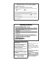 3
3
-
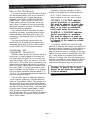 4
4
-
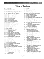 5
5
-
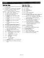 6
6
-
 7
7
-
 8
8
-
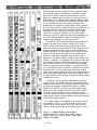 9
9
-
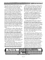 10
10
-
 11
11
-
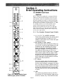 12
12
-
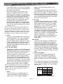 13
13
-
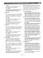 14
14
-
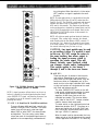 15
15
-
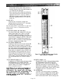 16
16
-
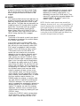 17
17
-
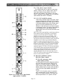 18
18
-
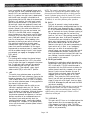 19
19
-
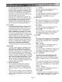 20
20
-
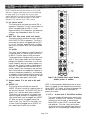 21
21
-
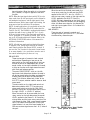 22
22
-
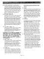 23
23
-
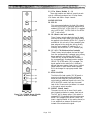 24
24
-
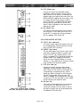 25
25
-
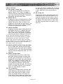 26
26
-
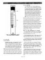 27
27
-
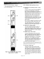 28
28
-
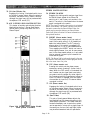 29
29
-
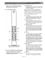 30
30
-
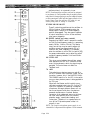 31
31
-
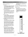 32
32
-
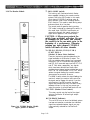 33
33
-
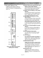 34
34
-
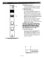 35
35
-
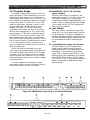 36
36
-
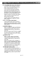 37
37
-
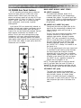 38
38
-
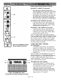 39
39
-
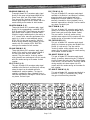 40
40
-
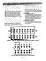 41
41
-
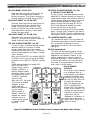 42
42
-
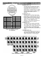 43
43
-
 44
44
-
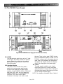 45
45
-
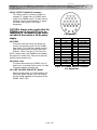 46
46
-
 47
47
-
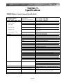 48
48
-
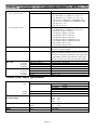 49
49
-
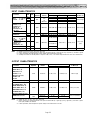 50
50
-
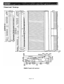 51
51
-
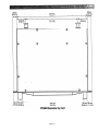 52
52
-
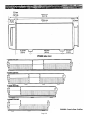 53
53
-
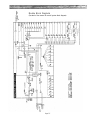 54
54
-
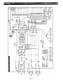 55
55
-
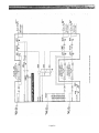 56
56
-
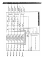 57
57
-
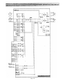 58
58
-
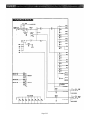 59
59
-
 60
60
-
 61
61
-
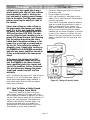 62
62
-
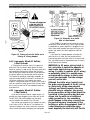 63
63
-
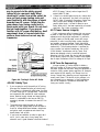 64
64
-
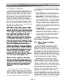 65
65
-
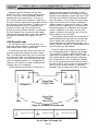 66
66
-
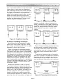 67
67
-
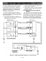 68
68
-
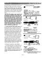 69
69
-
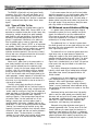 70
70
-
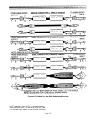 71
71
-
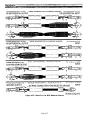 72
72
-
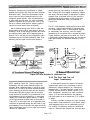 73
73
-
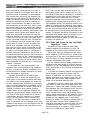 74
74
-
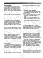 75
75
-
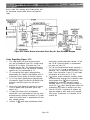 76
76
-
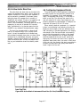 77
77
-
 78
78
-
 79
79
-
 80
80
-
 81
81
-
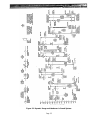 82
82
-
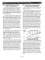 83
83
-
 84
84
-
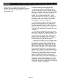 85
85
-
 86
86
-
 87
87
-
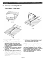 88
88
-
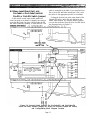 89
89
-
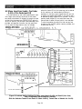 90
90
-
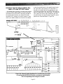 91
91
-
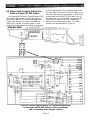 92
92
-
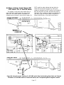 93
93
-
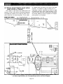 94
94
-
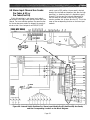 95
95
-
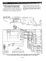 96
96
-
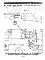 97
97
-
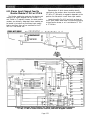 98
98
-
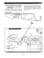 99
99
-
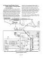 100
100
-
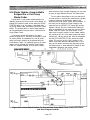 101
101
-
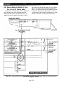 102
102
-
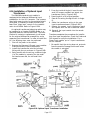 103
103
-
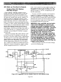 104
104
-
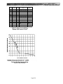 105
105
-
 106
106
-
 107
107
-
 108
108
-
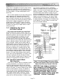 109
109
-
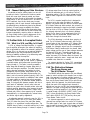 110
110
-
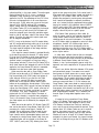 111
111
-
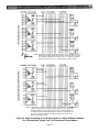 112
112
-
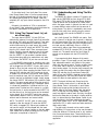 113
113
-
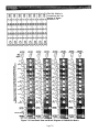 114
114
-
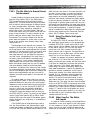 115
115
-
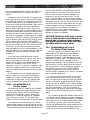 116
116
-
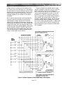 117
117
-
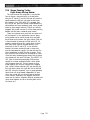 118
118
-
 119
119
-
 120
120
-
 121
121
-
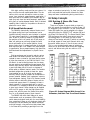 122
122
-
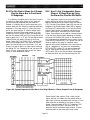 123
123
-
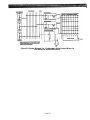 124
124
-
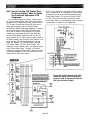 125
125
-
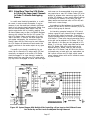 126
126
-
 127
127
-
 128
128
-
 129
129
-
 130
130
-
 131
131
-
 132
132


Yamaha PM4000 Manual de usuario
- Categoría
- Mezcladores de audio
- Tipo
- Manual de usuario
en otros idiomas
- français: Yamaha PM4000 Manuel utilisateur
- italiano: Yamaha PM4000 Manuale utente
- English: Yamaha PM4000 User manual
- Deutsch: Yamaha PM4000 Benutzerhandbuch
- русский: Yamaha PM4000 Руководство пользователя
- Nederlands: Yamaha PM4000 Handleiding
- português: Yamaha PM4000 Manual do usuário
- dansk: Yamaha PM4000 Brugermanual
- polski: Yamaha PM4000 Instrukcja obsługi
- čeština: Yamaha PM4000 Uživatelský manuál
- svenska: Yamaha PM4000 Användarmanual
- Türkçe: Yamaha PM4000 Kullanım kılavuzu
- română: Yamaha PM4000 Manual de utilizare
Artículos relacionados
-
Yamaha MC3204II El manual del propietario
-
-
-
-
-
-
-
-
-
Otros documentos
-
M-Audio Octane Guía del usuario
-
Peavey VSX II El manual del propietario
-
-
Focusrite Platinum TwinTrak PRO El manual del propietario
-
Peavey AM 4 Mini Automixer El manual del propietario
-
-
Shure DJ Equipment FP42 Manual de usuario
-
-
B&K 1652 Manual de usuario
-
Eden WT500 Guía de inicio rápido