
Manual de instrucciones
SOPORTE PARA PANTALLAS
DE 17" A 42"
Antes de utilizar el producto, lee el siguiente instructivo.
La información que se muestra en este manual sirve únicamente como referencia sobre el producto. Debido a actualizaciones pueden
existir diferencias. Por favor, consulta nuestra página web www.steren.com para obtener la versión más reciente de este manual.
1018m
STV-034
V2.2
CONTENIDO
HERRAMIENTAS NECESARIAS
C (4 tornillos)
(1 Soporte)
A
M5X10
F (8 tornillos)
M5X15
D (4 rondanas)
M5
G (8 tuercas)
2”
H (2 taquetes)
2”
E (2 pijas)
B (4 brazos)
M6X16
(4 tornillos)
M6
(4 rondanas)
Únicamente para VESA 200 x 200
PREPARATIVOS PARA LA INSTALACIÓN
INSTALACIÓN DEL SOPORTE
Localiza el lugar* donde deseas instalar el soporte; colócalo sobre la superficie para asegurarte de
que la instalación será correcta y verifica que esté nivelado usando la burbuja central del nivelador.
1
Utiliza una broca de 10 mm para perforar sobre las marcas que realizaste, a una profundidad de 2”.
1
Realiza las marcas para las perforaciones.
*Asegúrate de que no haya tuberías ocultas con cableado eléctrico, gas o agua.
2
a) Sobre concreto
Perfora
(2")
ø 10mm
(ø 3/8")
50,9 mm
Inserta los taquetes (H) en los orificios. Monta el soporte y fíjalo con las pijas (E).
2
E
A
H
E
Monta el soporte y fíjalo con las pijas (E).
2
Utiliza una broca de 3 mm para perforar sobre las marcas que realizaste, a una profundidad de 2”.
1
b) Sobre madera
Perfora
ø 3 mm
(2 ")
50,9 mm
A
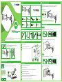
Coloca los brazos (B) en cada esquina de la base del soporte y fíjalos con las
tuercas (G) y los tornillos (F) en el orden que se muestra.
Utiliza 4 tornillos (C) y las 4 rondanas (D) para fijar el soporte en la parte posterior de la
pantalla.
COLOCACIÓN DE BRAZOS
INSTALACIÓN DE PANTALLA
F
B
G
Usa un desarmador y una llave española de 8 mm para apretar las piezas
No instales p
antallas de más de 42” o con un peso mayor a 15 kg
Los tornillos suministrados son de
medidas estándar. Te recomenda-
mos consultar el manual de
instrucciones de tu pantalla para
obtener información acerca de los
tornillos necesarios para montarla
en un soporte
TV
TV
TV
C
D
AJUSTES
Afloja el seguro de rosca.
1
Inclina la pantalla para obtener el ángulo de visión deseado.
• El
ige una pared sólida y lisa para poder fijar con seguridad el soporte.
• No aprietes excesivamente los tornillos.
• Este producto está diseñado para uso en interiores; utilizarlo en exteriores podría ocasionar fallas y heridas personales.
• Evita las caídas del equipo, ya que podría sufrir daños.
• No excedas la capacidad de carga máxima de 15 kg.
• Este aparato no se destina para utilizarse por personas (incluyendo niños), cuyas capacidades físicas, sensoriales o mentales sean
diferentes o estén reducidas, o carezcan de experiencia o conocimiento.
• Los niños deben supervisarse para asegurar que no empleen el aparato como juguete.
PRECAUCIONES
2
Aprieta nuevamente el seguro de rosca hasta que el soporte
quede firme.
3
1
1
1
3
1
2
M4X16

Instruction manual
17” TO 42” TV STAND
Before using the product, read the following instructions.
The information shown in this manual serves only as a reference for the product. Due to updates there may be differences. Please
check our website www.steren.com for the most recent version of this manual.
1018m
STV-034
V2.2
CONTENT
NECESSARY TOOLS
C (4 screws)
(1 TV Stand)
A
M5X10
F (8 screws)
M5X15
D (4 washers)
M5
G (8 nuts)
2”
H (2 anchors)
2”
E (2 screws)
B (4 arms)
M6X16
(4 screws)
M6
(4 washers)
Only for VESA 200 x 200
Drill
(2")
ø 10mm
(ø 3/8")
50.9 mm
E
A
H
E
Drill
ø 3 mm
(2 ")
50.9 mm
A
Insert the anchors (H) in the holes. Mount the bracket and fix it with the screws (E).
2
Use a 3 mm drill bit to drill on the marks that you made, at a depth of 2 ".
1
b) On wood
Mount the support and fix it with the screws (E).
2
F
B
G
TV
TV
TV
C
D
1
1
1
3
1
2
PREPARATION FOR INSTALLATION
LLocate the place * where you want to install the TV stand; Place it on the surface to make sure that
the installation will be correct and verify that it is level using the central bubble of the leveler.
1
Make the drilling marks.
2
* Make sure there are no hidden pipes with electrical wiring, gas or water.
TV STAND INSTALLATION
Use a 10 mm drill bit to drill on the marks that you made, at a depth of 2 ".
1
a) On concrete
Place the arms (B) in each corner of the TV stand base and fix them with the
nuts (G) and the screws (F) in the order shown.
PLACING ARMS
Use a screwdriver and an 8mm spanish key to tighten the pieces
Use 4 screws (C) and the 4 washers (D) to fix the TV stand on the back of the screen.
TV SCREEN INSTALLATION
Do not instal
l screens larger than 42 "or weighing more than 15 kg
The screws supplied are standard
sizes. We recommend you consult
the instruction manual of your
screen to obtain information about
the screws needed to mount it in a
support
Loosen the lock of the knob.
1
Tilt the screen to obtain the desired view angle.
2
Tighten the lock of the knob again until the TV stand is fixed.
3
ADJUSTMENTS
CAUTIONS
•
Choose a solid and smooth wall to securely fix the stand.
• Do not over tighten the screws.
• This product is designed for indoor use; using it outdoors could cause personal injuries and failures.
• Avoid falling device, as it could be damaged.
• Do not exceed of 15 kg maximum weight capacity.
• This device is not intended for use by people (including children), whose physical, sensory or mental
abilities are different or reduced, or who lack experience or knowledge.
• Children should be supervised to ensure they do not use the device as a toy.
M4X16
-
 1
1
-
 2
2


en otros idiomas
- English: Steren STV-034 Owner's manual
Artículos relacionados
-
Steren STV-116 El manual del propietario
-
-
-
-
-
-
-
-
-