Generac 006001-0 El manual del propietario
- Categoría
- Generadores de poder
- Tipo
- El manual del propietario
Este manual también es adecuado para

Owner'sManual
5500Watt LP SeriesPortableGenerator
ModelNo.006001-0
,_ DEADLYEXHAUSTFUMES! ONLYuse OUTSIDE
far away from windows, doors and vents!
_k NOT iNTENDED FOR USE iNCRiTiCAL
LIFESUPPORTAPPLiCATiONS.
,_ SAVE this manual. Provide this manual to
any operatorof the generator.
www.generac.com or 1-888-436-3722 This manual should remain with the unit.

WARNING!
California Proposition 65
Engine exhaust and some of its constituents are known to the state of California to cause cancer,
birth defects, and other reproductive harm.
WARNING!
California Proposition 65
This product contains or emits chemicals known to the state of California to cause cancer,
birth defects, and other reproductive harm.

Tableof Contents
Section 1" Introductionand Safety Rules .......................................................... 1
1.1 Read This Manual Thoroughly ................................................................................ 1
1.2 Safety Rules .............................................................................................. 1
Section
2.1
2.2
2.3
2.4
2.5
2.6
2.7
2: General Information .................................................................. 5
Unpacking ............................................................................................... 5
Assembly ................................................................................................ 5
Emissions Information ...................................................................................... 6
Product Specifications ...................................................................................... 6
Know The Generator ....................................................................................... 6
Connection Plugs.......................................................................................... 8
Hourmeter ............................................................................................... 8
Section
3.1
3.2
3.3
3.4
3.5
3.6
3.7
3: Operation ........................................................................... 9
How To Use The Generator .................................................................................. 9
Don't Overload the Generator ............................................................................... 10
Wattage Reference Guide .................................................................................. 10
Before Starting the Generator ............................................................................... 11
Starting the Generator ..................................................................................... 12
Stopping The Engine ...................................................................................... 12
Low Oil Level Shutdown System ............................................................................. 12
Section
4.1
4.2
4.3
4.4
4.5
4.6
4.7
4: Maintenance ........................................................................ 13
Maintenance Schedule..................................................................................... 13
General Recommendations ................................................................................. 13
Service Air Filter.......................................................................................... 14
Valve Clearance.......................................................................................... 15
Generator Storage ........................................................................................ 15
Long Term Storage........................................................................................ 16
Other Storage Tips........................................................................................ 16
Section 5: Troubleshooting .................................................................... 17
5.1 Troubleshooting Guide..................................................................................... 17
5,500 Watt LP Series Portable Generator iii

Table of Contents
This page intentionally left blank.
iv EnterPublicationTitleHere

Section7
Introduction andSafetyRules
Thank you for purchasing this model by Generac Power Systems, Inc.
This model is a compact, high performance, air-cooled, engine driven
generator designed to supply electrical power to operate electrical
loads where no utility power is available or in place of utility due to a
power outage.
1.1 -- READ THIS MANUAL THOROUGHLY
If any portion of this manual is not understood, contact the nearest
Authorized Dealerfor starting, operating and servicing procedures.
The operator is responsible for proper and safe use of the equipment.
We strongly recommend that the operator read this manual and thor-
oughly understand all instructions before using the equipment. We
also strongly recommend instructing other users to properly start and
operate the unit. This prepares them if they need to operate the equip-
ment in an emergency.
The generator can operate safely, efficiently and reliably only if it is
properly located, operated and maintained. Before operating or ser-
vicing the generator:
• Becomefamiliar with and strictly adhere to all local, state and
national codes and regulations.
• Study all safety warnings in this manual and on the product care-
fully.
Become familiar with this manual and the unit before use.
The manufacturer cannot anticipate every possible circumstance that
might involve a hazard. The warnings in this manual, and on tags and
decals affixed tothe unit are, therefore, not all inclusive. Ifusing a pro-
cedure, work method or operating technique that the manufacturer
does not specifically recommend, ensure that it is safe for others. Also
make sure the procedure, work method or operating technique uti-
lized does not render the generator unsafe.
THE INFORMATION CONTAINED HEREIN WAS BASED ON
MACHINES IN PRODUCTION AT THE TIME OF PUBLICATION.
GENERAC RESERVES THE RIGHT TO MODIFY THIS MANUAL AT
ANY TIME.
Savetheseinstructions for future reference.If you loan this
device to someone,ALWAYSloanthese instructions to the indi-
vidual aswell.
1.2 -- SAFETYRULES
Throughout this publication, and on tags and decals affixed to the
generator, DANGER, WARNING, CAUTION and NOTE blocks are
used to alert personnel to special instructions about a particular oper-
ation that may be hazardous if performed incorrectly or carelessly.
Observe them carefully. Their definitions are as follows:
INDICATES A HAZARDOUS SITUATION OR ACTION WHICH, IF
NOT AVOIDED, WILL RESULT IN DEATH OR SERIOUS INJURY.
CAUTION!
Indicatesa hazardoussituation or action which, if not avoided,
could result in deathor serious injury.
Indicates a hazardous situation or action which, if not
avoided, could result in minor or moderate injury.
NOTE:
Notes contain additional information important to a procedure
and will be found within the regular text body of this manual.
These safety warnings cannot eliminate the hazards that they indi-
cate. Common sense and strict compliance with the special instruc-
tions while performing the action or service are essential to preventing
accidents.
Four commonly used safety symbols accompany the DANGER,
WARNING and CAUTION blocks. The type of information each indi-
cates is as follows:
/_ Thissymbol points out important safety information that,
if notfollowed, could endangerpersonal safetyand/or
property of others.
Thissymbol points out potential explosion hazard.
/_ Thissymbol points out potential fire hazard.
/_ Thissymbol points out potential electrical shock hazard.
5,500 Watt LP Series Portable Generator 1

Introduction and Safety Rules
1.2.1-- General Hazards
• NEVER operate in an enclosed area, in avehicle, or indoors
EVEN IF doors and windows are open.
• For safety reasons, the manufacturer recommends that the main-
tenance of thisequipment is carried out byan Authorized Dealer.
Inspect the generator regularly, and contact the nearest Autho-
rized Dealer for parts needing repair or replacement.
• Operate generator only on level surfaces andwhere it will not be
exposed to excessive moisture, dirt, dust or corrosive vapors.
• Keep hands, feet, clothing, etc., away from drive belts, fans, and
other moving parts. Never remove any fan guard or shield while
the unit is operating.
• Certain parts of the generator get extremely hot during operation.
Keep clear of the generator until it has cooled to avoid severe
burns.
• DoNOT operate generator in the rain.
• Donot alter the construction of the generator or change controls
which might create an unsafe operating condition.
• Neverstart or stop the unit with electrical loads connected to
receptacles AND with connected devices turned ON. Start the
engine and let it stabilize before connecting electrical loads. Dis-
connect all electrical loads before shutting down the generator.
• Donot insert objects through unit's cooling slots.
• When working on this equipment, remain alert at all times. Never
work on the equipment when physically or mentally fatigued.
• Neveruse the generator or any of its parts as a step. Stepping on
the unit can stress and break parts, and may result in dangerous
operating conditions from leaking exhaust gases, fuel leakage, oil
leakage, etc.
1.2.2-- Exhaust & Location Hazards
Neveroperatein an enclosedareaor indoors! NEVERuse in the
home,in avehicle, or in partly enclosedareassuch asgarages,
EVENIF doors and windows areopen! ONLYuseoutdoors and
farfrom openwindows, doors,vents, and in anareathatwill not
accumulatedeadlyexhaust.
Using a generator indoors CAN KiLL YOU IN MINUTES.
Generator exhaust contains carbon monoxide. This is
a poison you cannot see or smell.
NEVER use inside a home
or garage, EVEN IF doors
and windows are open.
Only use OUTSIDE and
far away from windows,
dOOrS, and vents.
The engine exhaust fumes contain carbon monoxide, which you
cannot see or smell. This poisonous gas, if breathed in sufficient
concentrations, can cause unconsciousness or even death.
• Adequate, unobstructed flow of cooling and ventilating air is criti-
cal to correct generator operation. Do not alter the installation or
permit even partial blockage of ventilation provisions, as this can
seriously affect safe operation of the generator. The generator
MUST be operated outdoors.
• Thisexhaust system must be properly maintained. Do nothing that
might render the exhaust system unsafe or in noncompliance with
any local codes and/or standards.
• Always use a battery operated carbon monoxide alarm indoors,
installed according to the manufacturers instructions.
• If you start tofeel sick, dizzy,or weak after the generator has been
running, move to fresh air IMMEDIATELY.See a doctor, as you
could have carbon monoxide poisoning.
1.2.3-- Electrical Hazards
• The generator produces dangerously high voltage when in opera-
tion. Avoid contact with bare wires, terminals, connections, etc.,
while the unit is running, even on equipment connected to the
generator. Ensureall appropriate covers, guards and barriers are
in place before operating the generator.
• Never handle any kind of electrical cord or device while standing
in water, while barefoot or while hands or feet arewet. DANGER-
OUS ELECTRICAL SHOCK MAY RESULT.
• The National Electric Code (NEC) requires the frame and external
electrically conductive parts of the generator be properly con-
nected to an approved earth ground. Local electrical codes may
also require proper grounding of the generator. Consult with a
local electrician for grounding requirements in the area.
• Use a ground fault circuit interrupter in any damp or highly con-
ductive area (such as metal decking or steel work).
• Do not use worn, bare, frayed or otherwise damaged electrical
cord sets with the generator.
• Before performing any maintenance on the generator, discon-
nect the engine starting battery (if equipped) to prevent accidental
start up. Disconnect the cable from the battery post indicated by a
NEGATIVE, NEG or (-) first. Reconnect that cable last.
• Incase of accident caused by electric shock, immediately shut
down the source of electrical power. If this is not possible, attempt
to free the victim from the live conductor. AVOID DIRECT CON-
TACT WITH THE VICTIM. Use a non-conducting implement, such
as a rope or board, tofree the victim from the live conductor, if the
victim is unconscious, apply first aid and get immediate medical
help.
2 5,500 Watt LP Series Portable Generator

Introduction and Safety Rules
1.2.4-- Fire Hazards
• LPgas is highly EXPLOSIVE.
• Flammable gas under pressure can cause a fire or explosion if
ignited.
LP gas is heavier that air and can settle in low places while dissi-
pating.
LPgas has a distinctive odor added to help detect potential leaks
quickly.
Inany propane gas fire, flames should not be extinguished unless
by doing so the fuel supply valve can be turned OFF.
Ifthe fire isextinguished and a supply of fuel is not turned OFF,an
explosion hazard greater than the fire hazard could be created.
When exchanging LPcylinders, be surethe cylinder valve is of the
same type.
Wipe up any fuel or oil spills immediately. Ensure that no combus-
tible materials are lefton or near thegenerator. Keepthe area sur-
rounding the generator clean and free from debris and keep a
clearance of five (5) feet on all side to allow for proper ventilation
of the generator.
• Do not insert objects through unit's cooling slots.
• Do not operate the generator if connected electrical devices over-
heat, if electrical output is lost, if engine or generator sparks or if
flames or smoke are observed while unit is running.
• Keep a fire extinguisher near the generator at all times.
NOTE:
Thisgeneratoris equipped witha spark arrestor muffler. The
spark arrestor must be maintainedin effective workingorder by
theowner/operator.In thestate of California,a spark arrestor is
required by law (Section4442of thePublic Resources Code).
Otherstates may havesimilar laws.Federallawsapply on
federallands.
ModelNumber
Serial Number
Figure 1" Unit ID Location
1.2.5-- Standards Index
1. National Fire Protection Association (NFPA) 70: The NATIONAL
ELECTRIC CODE (NEC) available from www.nfpa.org
2. National Fire Protection Association (NFPA) 5000: BUILDING
CONSTRUCTION AND SAFETY CODE available from
www.nfpa.org
3. International Building Code available from www.iccsafe.org
4. Agricultural Wiring Handbook available from www.rerc.org,
Rural Electricity Resource Council P.O.Box 309 Wilmington, OH
45177-0309
5. ASAE EP-364.2 Installation and Maintenance of Farm Standby
Electric Power available from www.asabe.org, American Society
of Agricultural & Biological Engineers 2950 Niles Road, St.
Joseph, MI 49085
This list is not all inclusive. Check with the Authority Having Local
Jurisdiction (AHJ) for any local codes or standards which may be
applicable to your jurisdiction.
5,500 Watt LP Series Portable Generator 3

Introduction and Safety Rules
This page intentionally left blank.
4 5,500 Watt LP Series Portable Generator

Section2 GeneralInformation
2.1-- Unpacking
• Remove all packaging material.
• Remove separate accessory box.
• Remove the generator from carton.
2.1.1-- Accessories
Check all contents. Ifany parts are missing or damaged, locate an
authorized dealer at 1-888-436-3722.
Product Registration and Warranty Cards
1- Owner's Manual
1- Liter Oil SAE 10W-30
2 - Never-Flat Wheels
2 - Frame Feet
1- FuelCylinder Retaining Strap
1- Oil Funnel
1- Hardware Bag (containing the following):
-- 2-Rubber Feet (A) -- 4-M8 Bolt (Long) (E)
-- 2-5/8" Axle Pins (B) - 2-M6 Bolts (Long) (F)
-- 2-Cotter Pins (Hairpin) (C) - 4-Hex Flanged M8 Nuts (G)
-- 2-5/8" Flat Washers (D) - 2-Hex Flanged M6 Nuts (H)
-- Spark Plug Service Tool - 1- Cotter Pin (Strap)
2.2-- Assembly
The generator requires some assembly prior to using it. Ifproblems
arise when assembling the generator, please call the Generator Help-
line at 1-888-436-3722.
2.2.1-- Assembling the Accessory Kit
The wheels are designed into the unit to greatly improve the portabil-
ity of the generator.
You will need the following tools to properly install the accessory kit.
• Needle Nose Pliers
• Ratchet and 8mm, 10mm, and 13mm sockets
• 12ram, 10ram, and 13rambox wrenches
NOTE:
The wheels are not intended for over-the-road use.
1. Referto Figure 2-1 and install the Wheels as follows:
-- Slide the Axle Pin through the Wheel, Wheel Bracket on the
frame and 5/8" Flat Washer.
-- Insert the Cotter Pinthrough the Axle Pin to lock into place.
.
Referto Figure 2-2 and install the Frame Feet and Rubber Bum-
pers as shown.
-- Slide the Rubber Bumper [v16Bolts through the Frame Foot,
Rubber Bumper. Then install the Locking Flange Nuts.
Tighten securely.
-- Slide the Hex Head Boltsthrough the holes in the Frame Rail.
-- Slide the Frame Foot onto the Hex Head Bolts then install the
Locking Flange Nuts. Tighten securely.
Figure 2-1: Wheel & FeetAssembly
G
E
H
Figure 2-2: Frame Feet and Rubber Bumpers
Figure 2-3: Fuel Cylinder Retaining Strap
5,500 Watt LP Series Portable Generator 5

GeneralInformation
2.3-- Emissions Information
The Environmental Protection Agency (and California Air Resource
Board for generators certified to CA standards) requires that this gen-
erator comply with exhaust andevaporative emission standards.
Locate the emissions compliance decal on the engine to determine
what standards the generator meets, and to determine which war-
ranty applies. This generator is certified to operate on LP fuel (liquid
propane). The emission control system includes the following compo-
nents (if equipped):
• Airlnduction System
-- Intake Pipe / Manifold
-- Air Cleaner
• Fuel System
-- Carburetor/Mixer Assembly
-- Fuel Regulator
• Ignition System
-- Spark Plug
--ignition Module
• Exhaust System
-- Exhaust Manifold
-- Muffler
-- PulsedAir Valve
-- Catalyst
2.4-- Product Specifications
2.4.1-- Generator Specifications
Rated Power........................................................................ 5.5 kW***
Surge Power........................................................................ 6.875 kW
Rated AC Voltage .................................................................. 120/240
Rated AC Load
Current @ 240V ............................................................ 22.9 Amps**
Current @ 120V............................................................ 45.8 Amps**
Rated Frequency ................................................. 60 Hz @3600 RPM
Phase............................................................................. Single Phase
Operating Temperature Range........ 0° F (-17° C)to 110° F (43° C)*
* Operatingtemperaturerange:-18° C(0° F)to40°C(104° F).Whenoperatedabove
25° C(77° F)theremaybeadecreaseinpower.
** Maximumwattageandcurrentaresubjectto,andlimitedby,suchfactorsasfuelBtu
content,ambienttemperature,altitude,enginecondition,etc..Maximumpower
decreasesabout3.5%foreach1,000feetabovesealevel;andwillalsodecrease
about1%foreach6° C(10° F)above16°C(60° F)ambienttemperature.
2.4.2-- Engine Specifications
Displacement ............................................................................ 389 cc
Spark Plug Type ......................... NHSP LDF7TC or Champion NgYC
Spark Plug Part No......................................................... 0G84420101
Spark Plug Gap .......................... 0.028-0.031 inch or (0.70-0.80 ram)
Fuel Capacity .............................................. 20 or 30 Pounds LPTank
Oil Type............ See Chart in "Before Starting the Generator" Section
Oil Capacity ................................................................ 1.0 L (1.06 Qt.)
Run Time at 50% Load
20 lb. LP Tank......................................................... 4 Hours, 46 Min.
30 lb. LP Tank........................................................... 7 Hours, 9 Min.
2.4.3-- High Altitude Operation
At high altitude, the standard carburetor air-fuel mixturewill be too
rich. Performance will decrease and fuel consumption will increase. A
very rich mixture will also foul the spark plug and cause hard starting.
Operation at an altitude that differs from that at which this engine was
certified, for extended periods of time, may increase emissions.
High altitude performance can be improved by specific modifications
to the carburetor. Ifyou always operate your engine at altitudes above
5,000 feet (1,500 meters), have your servicing dealer perform this car-
buretor modification. This engine, when operated at high altitude with
the carburetor modifications for high altitude use, will meet each emis-
sion standard throughout its useful life.
See the table below to determine when an altitude kit is required..
Altitude
Units Fuel
Range"
0-5000ff
5.5kW LP
5000- 7000 ff
Kit PartNumbers
NotRequired
0K2111
* Elevation above sea level.
** At elevations above 7000 feet the engine may experience decreased
performance.
NOTE:
Call 1-888-GENERAC to order an altitude kit if you are operating
the generator at 5000 - 7000 feel
2.5-- Know The Generator
Read the Owner's Manual and Safety Rules before operating this
generator.
Compare the generator to Figures 2-4through 2-8 to becomefamiliar-
ized with the locations of various controls and adjustments.
1. 120 Volt AC, 20 Amp, Duplex Receptacle - Supplies electrical
power forthe operation of 120 VoltAC, 20 Amp, single-phase, 60
Hz electrical lighting, appliance, tool and motor loads.
2. 120/240 Volt AC, 30 Amp Locking Receptacle - Supplies elec-
trical power for the operation of 120and/or 240 Volt AC, 30Amp,
single-phase, 60 Hz, electrical lighting, appliance, tool and motor
loads.
3. Circuit Breakers (AC) - A 2-pole circuit breaker protects the
rated output of the generator. Each duplex receptacle is provided
with a push-to-reset circuit breaker to protect the generator
against electrical overload.
4. Hourmeter- Tracks hours of operation to perform required
maintenance.
6 5,500 Watt LP Series Portable Generator

General Information
t
2
i/
4 3
Figure 2-4: Control Panel
5. Oil Drain - Use to drain engine oil.
6. Grounding Lug- Ground the generator to an approved earth
ground here. See "Grounding the Generator" for details.
7. Oil Fill - Add oil here and check level with dipstick.
J_'_ -- _ ............. zo
Figure 2-5: Generator Grounding & Oil Drain/Fill
8. Air Filter- Filters intake air as it is drawn into the engine.
9. Muffler- Quiets the engine, includes the spark arrestor.
10. Recoil Starter Handle - Use to start the engine manually.
11. Handle- Pivot and retract for storage. Press the spring-loaded
button to move handles.
12. Tank Bracket - Supports the LP Fuel Cylinder with two (2) lock-
ing pins in place and folds up for transport or storage when not in
use with one (1)locking pin.
13. Fuel Tank- Standard20 or30 poundcapacityLPtankwithType1,
righthandAcmethreadswithprotectivecap(soldseparately).
14. Power Dial - Combines the engine choke, the LP regulator
Primer and the engine ignition On/Off switch in one location.
15. Tank Strap - Rubber strap assembly attaches to the cradle with
a Cotter Pinon one side and slides into a keyhole slot on the
other side of the cradle. Secure the LP Fuel Cylinder inplace.
16. Fuel Shut Off-Valve is on the fuel tank.
9
Figure 2-6: Generator Controls
14
13
16
Figure 2-7: Generator Controls
15
LockingPins
Figure 2-8: Tank Bracket
5,500 Watt LP Series Portable Generator 7

General Information
2.6-- Connection Plugs
2.6.1-- 120 VAC, 20Amp, Duplex Receptacle
This isa 120Volt outlet protected against overload by a20 Amp push-
to-reset circuit breaker (Figure 2-9). Use each socket to power 120
VoltAC, single phase, 60 Hz electrical loads requiring up to a com-
bined 2400 watts (2.4 kW) or 20 Amps of current. Use only high qual-
ity, well-insulated, 3-wire grounded cord sets rated for 125 Volts at 20
Amps (or greater). Each outlet is protected bya 1-pole, 20 Amp,
push-button circuit breaker.
Keep extension cords as short as possible, preferably lessthan 15
feet long, to prevent voltage drop and possible overheating of wires.
Figure 2-9:120 Volt AC, 20 Amp, Duplex Receptacle
2.6.2-- 120/240VAC, 30Amp Receptacle
Use a NEMA L14-30P Plugwith this receptacle (rotate tolock/unlock).
Connect a suitable 4-wire grounded cord set to the plug and to the
desired load. The cord set should be rated for 250 Volts AC at 30
Amps (or greater) (Figure 2-10).
2.7-- Hourmeter
The Hourmeter tracks hours of operation for scheduled maintenance
(Figure 2-11):
There will be a "CHG OIL" message every 100hours. The message
will flash one hour before and one hour after each 100 hour interval,
providing a two hour window to perform service.
This message will actually beginflashing at 99 hours anddisable itself
at 101 hours again, providing atwo hour window to perform the ser-
vice.
Every 200 hours the "SVC" icon on the lower left hand corner of the
display will flash. The message will flash one hour before and one
hour after each 200 hour interval providing a two hour window to per-
form service.
0000.0[
71 _] i _.
HOUR GLASS RESETBUTTON
GRAPHIC (IF EQUIPPED)
Figure 2-11: Hourmeter
When the hour meter is in the Flash Alert mode, the maintenance
message will always alternate with elapsed time in hours and tenths.
The hours will flash four times, then alternate with the maintenance
message four times until the meter resets itself.
• 100 hours - CHG OIL-- Oil Change Interval (Every 100hrs)
• 200 hours - SVC -- Service Air Filter (Every 200 hrs)
NOTE:
Thehour glass graphic will flash on and off when the engine
is running. This signifies that the meter is tracking hours
of operation.
Figure 2-10:120/240 VAC, 30 Amp Receptacle
Use this receptacle to operate 120 Volt AC, 60 Hz, single phase loads
requiring up to 3000 watts (3.0 kW) of power at 25 Amps or 240 Volt
AC, 60 Hz, single phase loads requiring up to 5500 watts (5.5 kW) of
power at 22.9 Amps. The outlet is protected by a 2-pole 25 Amp
rocker type circuit breaker.
8 5,500 Watt LP Series Portable Generator

Section3
Operation
3.1-- How ToUse The Generator
See the "ToStart the Engine" section for how to safely start and stop
the generator and how to connect and disconnect loads. If there are
any problems operating the generator, please call the generator help-
line at 1-888-436-3722.
//_ Neveroperate in an enclosedarea or indoors! NEVER
usein the home,in avehicle,or in partly enclosed areas
such asgarages, EVENIFdoors andwindows are open!
ONLYuseoutdoors and farfrom open windows, doors,
vents, and in an areathat will not accumulatedeadly
exhaust.
//_ Theengine exhaustfumes contain carbon monoxide,
which you cannot seeor smell. This poisonous gas,if
breathedin sufficient concentrations, cancause uncon-
sciousnessor evendeath.
//_ Adequate,unobstructed flow of cooling and ventilating
air is critical to correct generatoroperation. Donot alter
theinstallation or permit even partialblockage of ventila-
tion provisions, asthis can seriouslyaffect safeopera-
tion of thegenerator.ThegeneratorMUSTbeoperated
outdoors.
//_ Thisexhaust system mustbe properly maintained.Do
nothing that might render theexhaustsystem unsafeor
in noncompliancewith any localcodes and/orstandards.
3.1.1-- Grounding The Generator When Used As A
Portable
This generator has an equipment ground that connects the generator
frame components to the ground terminals on the AC output recepta-
cles (see NEC 250.34 (A) for explanation). This allows the generator
to be used as aportable without grounding the frame of the generator
as specified in NEC 250.34.
3.1.1.1 -- Special Requirements
There may be Federal or State Occupational Safety and Health
Administration (OSHA) regulations, local codes, or ordinances that
apply to the intended use of the generator.
Please consult a qualified electrician, electrical inspector, or the local
agency havingjurisdiction:
• Insome areas, generators are required to be registered with local
utility companies.
• If the generator is used at a construction site, there may be addi-
tional regulations which must be observed.
3.1.2-- Connecting The Generator To A Building's
Electrical System
When connecting directly to a building's electrical system, it is recom-
mended that a manual transfer switch is used. Connections for a por-
table generator to a building's electrical system mustbe made bya
qualified electrician and in strict compliance with all national and local
electrical codes and laws.
3.1.2.1 -- Grounding The Generator In A Building
Standby Application
//_ Alwaysusea battery operatedcarbon monoxidealarm
indoors, installed according to the manufacturer's
instructions.
Using a generator indoors CAN KiLL YOU iN MINUTES.
Generator exhaust contains carbon monoxide. This is
a poison you cannot see or smell.
NEVER use inside a home
or garage, EVEN iF doors
and windows are open.
Only use OUTSIDE and
far away from windows,
doors, and vents.
//_ TheNationalElectrical Coderequiresthat the frame and
externalelectrically conductive partsof thisgeneratorbe
properly connectedto an approvedearthground.
Local electrical codes may also require proper grounding of the unit
(Figure 3-1). For that purpose, connecting a No. 10 AWG (American
Wire Gauge) stranded copper wire to the grounding lug and to an
earth-driven copper or brass grounding rod (electrode) provides ade-
quate protection against electrical shock. However, local codes may
vary widely. Consult with a local electrician for grounding require-
ments in the area.
Proper grounding of the generator will help prevent electrical
shock in the event of a ground fault condition in the generator or in
connected electrical devices. Proper grounding also helps dissipate
static electricity,which often builds up in ungrounded devices.
5,500 Watt LP Series Portable Generator 9

Operation
Figure 3-1: Grounding the Generator
3.2-- Don't Overload the Generator
Overloading a generator in excess of its rated wattage capacity can
result in damage to the generator and toconnected electrical devices.
Observe the following to prevent overloading the unit:
• Add up the total wattage of all electrical devices to be connected
at one time. This total should NOT be greater than the generator's
wattage capacity.
• The rated wattage of lights can be taken from light bulbs. The
rated wattage of tools, appliances and motors can usually be
found on a data label or decal affixed to the device.
• If the appliance, tool or motor does not give wattage, multiply volts
times ampere rating to determine watts (volts x amps =watts).
• Some electric motors, such asinduction types, require about three
times more watts of powerfor starting than for running. This surge
of power lasts only a few seconds when starting such motors.
Make sure to allow for high starting wattage when selecting elec-
trical devices to connect to the generator:
1. Figure the watts needed to start the largest motor.
2. Add to that figure the running watts of all other connected loads.
The Wattage Reference Guide is provided to assist in determining
how many items the generator can operate at one time.
NOTE:
All figures are approximate.Seedatalabel on appliancefor
wattagerequirements.
3.3-- Wattage Reference Guide
Device ..................................... Running Watts
*Air Conditioner (12,000 Btu) .......................... 1700
*Air Conditioner (24,000 Btu) .......................... 3800
*Air Conditioner (40,000 Btu) .......................... 6000
Battery Charger (20 Amp) .............................. 500
Belt Sander (3")..................................... 1000
Chain Saw......................................... 1200
Circular Saw (6-1/2")............................ 800 to 1000
*Clothes Dryer (Electric) .............................. 5750
*Clothes Dryer (Gas) .................................. 700
*Clothes Washer ..................................... 1150
Coffee Maker ....................................... 1750
*Compressor (1 HP) ................................. 2000
*Compressor (3/4 HP)................................ 1800
*Compressor (1/2 HP)................................ 1400
Curling Iron ......................................... 700
*Dehumidifier ........................................ 650
Disc Sander (9") .................................... 1200
Edge Trimmer ....................................... 500
Electric Blanket ...................................... 400
Electric Nail Gun .................................... 1200
Electric Range (per element) .......................... 1500
Electric Skillet ...................................... 1250
*Freezer ............................................ 700
*Furnace Fan (3/5 HP) ................................ 875
*Garage Door Opener ............................ 500 to 750
Hair Dryer ......................................... 1200
Hand Drill .................................... 250 to 1100
Hedge Trimmer ...................................... 450
Impact Wrench ...................................... 500
Iron .............................................. 1200
*Jet Pump .......................................... 800
Lawn Mower ....................................... 1200
Light Bulb .......................................... 100
Microwave Oven ............................... 700 to 1000
*Milk Cooler......................................... 1100
Oil Burner on Furnace ................................. 300
Oil Fired Space Heater (140,000 Btu)..................... 400
Oil Fired Space Heater (85,000 Btu) ...................... 225
Oil Fired Space Heater (30,000 Btu) ...................... 150
*Paint Sprayer, Airless (1/3 HP) ......................... 600
Paint Sprayer, Airless (hand-held) ....................... 150
Radio.......................................... 50 to 200
*Refrigerator ........................................ 700
Slow Cooker ........................................ 200
*Submersible Pump (1-1/2 HP)......................... 2800
*Submersible Pump (1 HP) ............................ 2000
*Submersible Pump (1/2 HP) .......................... 1500
*Sump Pump .................................. 800 to 1050
*Table Saw (10") .............................. 1750 to 2000
Television ..................................... 200to 500
Toaster ..................................... 1000 to 1650
Weed Trimmer....................................... 500
* Allow 3 times the listed watts for starting these devices.
10 5,500 Watt LP Series Portable Generator

Operation
3.4-- Before Starting the Generator
Prior to operating the generator, engine oil and LP fuel will need to be
added, as follows:
3.4.1-- Adding Engine Oil
All oil should meet minimum American Petroleum Institute (API) Ser-
vice Class SJ, SL or better. Use no special additives. Select the oil's
viscosity grade according to the expected operating temperature (also
see chart).
• Above 40° F,use SAE 30
• Below40 ° Fand down to 10° F, use 10W-30
• Below10° F,usesynthetic5W-30
NOTE:
Synthetic oil should only be usedafter a 50hour break-inperiod.
Thisis important to ensureproper cylinder wallandring seating.
mEm
°F =20 =10 0 10 20 32 40 60
oc4'o -_o -;o o 1'o 2;
Temperature Range of Expected Use
80 100
A CAUTION!
Any attempt to start the engine before it has been properly
serviced with the recommended oil may result in an engine
failure.
1. Place generator on a level surface (not to exceed 15° in any
direction).
2. Clean area around oil fill and remove oil fill cap and dipstick.
3. Wipe dipstick clean.
4. Slowly fill engine with oil through the oil fill opening until it
reaches the full mark. Stopfilling occasionally to check oil level.
Be careful not to over fill.
5. Install oil fill cap andfinger tighten securely.
6. Check engine oil level before starting eachtime thereafter.
3.4.2-- Connecting LP Fuel Tank
//_ Donot useor store LP cylinder in a building, garageor
enclosedareaexceptas authorized by NFPA58or
B149.2(in Canada).
z_Do not checkfor leaks with a matchor flame.
//_ Thecylinder valveshould be left off (closed)when the
generatoris not in use.
NOTE:
Regulator inlet pressure range from LP tank is: 30 to 100psi.
• Use only standard 20 or 30 pound capacity LP tanks with Type 1,
right hand Acme threads with this generator. Verify the re-qualifi-
cation date on the tank has not expired. Donot use rusted or dam-
aged cylinders.
• All new cylinders must be purged of air and moisture prior to fill-
ing. Used cylinders that have not been plugged or kept closed
must also be purged.
• The purging process should be done by your propane gas sup-
plier. (Cylinders from an exchange supplier should have been
purged and filled properly already).
• Liftthe tank and place carefully in the rear tank bracket with the
connection point facing the front ofthe generator (Figure 3-2).
• Insert the fixed end into the side bracket with the smaller hole and
slide cotter pin in place. Firmly grasping the pivot end, stretch the
tank strap around the cylinder and slide the peg into the keyhole in
the other bracket.
• Remove the safety plug or cap from the cylinder valve.
• Attach the connector snugly into the valve. Remember, turn the
plastic coupling from the hose right to tighten or clockwise.
• Always position the cylinder so the connection between the valve
and the regulator won't cause sharp bends or kinks in the hose.
Figure 3-2: Position Tank
Check for leaks by spraying soapy water to the connections being
tested.
Ifbubbles appear, become larger in size or increase in number, a
leak exists.
• This must be corrected before using the generator. Contact your
local Authorized Service Facility for assistance.
• Contact with liquid contents of the cylinder will cause freeze burns
to the skin.
Do not allow children to tamper or play with the cylinder.
5,500 Watt LP Series Portable Generator 11

Operation
When transporting and storing, keep cylinder secured in an
upright position with cylinder valve turned off and the outlet
plugged. (usually by a plastic protective cap). Keep cylinders
away from heat and ventilated when in a vehicle.
3.5-- Starting the Generator
/_ Neverstart or stop enginewith electrical devices
plugged into the receptaclesANDdevices turnedon.
1. Unplug all electrical loads from the unit's receptacles before
starting the engine.
2. Make sure the unit is ina level position (not to exceed 15° in any
direction).
3. OPEN the Fuel Shut-off Valve on the cylinder (Figure 3-2).
4. Turnengine POWER DIAL (Figure 3-3)to the #1 PRIME position
and press down on the dial for five (5) seconds to allow fuel to
enter the mixer.
5. Grasp the recoil handle and pull slowly until increased resistance
is felt. Brace one foot on the frame cross bar, and then pull rap-
idly up and away twice to PRIMEthe fuel system.
6. Turnthe POWER DIAL to the #2 RUNposition.
7. Grasp the recoil handle and pull slowly until increased resistance
is felt. Brace one foot on the frame cross bar, and then pull rap-
idly up and away to start the engine. Pull recoil up to two (2)
more times if necessary to start the engine.
NOTE:
ff engine does not start or stay running, repeat the start
sequence starting at Step 4 above.
IMPORTANT: Do not overload the generator. Also, do not overload
individual panel receptacles. These outlets are protected against
overload with push-to-reset-type circuit breakers. If amperage rating
of any circuit breaker is exceeded, that breaker opens and electrical
output to that receptacle is lost. Read "Don't Overload the Generator"
carefully.
Figure 3-3: Power Dial
3.6-- Stopping The Engine
1. Shut off all loads, then unplug the electrical loads from generator
panel receptacles. Never start or stop the engine with electrical
devices plugged in and turned on.
2. Let engine runat no-load for several minutes to stabilize the
internal temperatures of engine and generator.
3. Move the Power Dial to OFF/STOP position.
4. Close fuel valve.
3.7-- Low Oil Level Shutdown System
The engine isequipped with a low oil level sensor that shuts down the
engine automatically when the oil level drops below a specified level.
If the engine shuts down by itself and the cylinder has sufficient fuel,
check engine oil level.
12 5,500 Watt LP Series Portable Generator

Section4 Maintenance
4.1-- MaintenanceSchedule
Follow the calendar intervals. More frequent service is required when
operating in adverse conditions noted below.
Check Oil Level............................................................... At Each Use
Change Oil :1:................................ *Every 100 hours or Every Season
Check Valve Clearance ............................................ ***Every Season
Service Air Filter ........................ ** Every 200 hours or Every Season
Replace Spark Plug ...................................................... Every Season
Changeoilafterfirst30hoursofoperationtheneveryseason.
* Changeoilandoilfiltereverymonthwhenoperatingunderheavyloadorinhightem-
peratures.
** Cleanmoreoftenunderdirtyordustyoperatingconditions.Replaceairfilterpartsif
theycannotbeadequatelycleaned.
***Checkvalveclearanceandadjustifnecessaryafterfirst50hoursofoperationand
every300hoursthereafter.Thisrequiressomeenginedisassembly.Werecom-
mendcontactinganAuthorizedServiceDealerforthisadjustment.
NOTE:
Onceayear replace thespark plug and replacetheair filter.A
newsparkplug andcleanair filter assureproper fuel-airmixture
and help the enginerun better and last longer.
4.2-- General Recommendations
The warranty of the generator does not cover items that have been
subjected to operator abuse or negligence. Toreceive full value from
the warranty, the operator must maintain the generator as instructed
in this manual.
Some adjustments will need to be made periodically to properly main-
tain the generator.
All adjustments in the Maintenance section of this manual should be
made at least once each season. Follow the requirements in the
"Maintenance Schedule".
4.2.1-- Generator Maintenance
Generator maintenance consists of keeping the unit clean and dry.
Operate and store the unit in a clean dry environment where itwill not
be exposed to excessive dust, dirt, moisture or any corrosive vapors.
Cooling air slots inthe generator must not become clogged with snow,
leaves, or any other foreign material.
Check the cleanliness of the generator frequently and clean when
dust, dirt, oil, moisture or other foreign substances are visible on its
exterior surface.
CAUTION!
//_ Neverinsert any object or toolthroughtheair cooling
slots, evenif the engine is not running.
4.2.2-- To Clean The Generator
Use a damp cloth to wipe exterior surfaces clean.
A soft, bristle brush may be used to loosen caked on dirt, oil, etc.
A vacuum cleaner may be used to pickup loose dirt and debris.
Lowpressure air (not to exceed 25 psi) may be used to blow away
dirt. Inspect cooling air slots and openings on the generator.
These openings must be kept clean and unobstructed.
NOTE:
DONOTusea garden hose to cleangenerator. Watercanenter
theengine fuelsystem and causeproblems. In addition, if water
enters thegenerator through cooling air slots, some water will
be retainedin voids and crevices of therotor and stator winding
insulation. Wateranddirt buildup on thegenerator internal wind-
ings will eventuallydecreasetheinsulation resistance of these
windings.
4.2.3-- Engine Maintenance
Whenworking on the generator,alwaysdisconnect
spark plug wirefrom sparkplug and keepwire awayfrom
spark plug.
4.2.4-- Checking Oil Level
See the "Before Starting the Generator" section for information on
checking the oil level. The oil level should be checked before each
use, or at least every eight hours of operation. Keepthe oil level main-
tained.
4.2.5-- Changing The Oil
Change the oil after the first 30 hours and every 100hours thereafter.
If running this unit under dirty or dusty conditions, or in extremely hot
weather, change the oil more often.
A CAUTION!
//_ Hotoil may cause burns. Allow engineto cool before
draining oil. Avoid prolonged or repeatedskin exposure
with usedoil. Thoroughly wash exposedareaswith soap.
Usethefollowing instructions to changethe oil after theengine
cools down:
1. Clean area around oil drain plug (Figure 4-1).
2. Remove oil drain plug from engine and oil fill plug to drain oil
completely into a suitable container.
3. When oil has completely drained, install oil drain plug and tighten
securely.
5,500 Watt LP Series Portable Generator 13

Maintenance
4. Fillenginewithrecommendedoil.(See"BeforeStartingtheGen-
erator"foroil recommendations).
5. Wipeupanyspilledoil.
6. Disposeofusedoilata propercollectioncenter.
Figure 4-1: Oil Drain Plug
4.2.6-- Replacing The Spark Plug
Use Champion N9YC spark plug or equivalent. Replace the plug
every 200 hours.
1. Stop the engine and shut off the fuel valve on the cylinder and
remove.
2. Using a 5mm Allen wrench, remove the four (4) button head
screws to the top cover and remove the front top cover to gain
access to the spark plug (Figure4-2).
Figure 4-2: Remove Screws
3. Remove the spark plug wire off ofthe plug and clean that area of
the cylinder head (Figure 4-3).
Figure 4-3: Remove Spark Plug Wire
4. Use a 21mm (13/16") spark plug tool (included) to remove the
spark plug.
5. Set the newspark plug's gapto 0.70-0.80 mm (0.028 - 0.031 in).
Install the correctly gapped spark plug into the cylinder head and
tighten enough to ensure the gasket compresses at (18.0 to 21.6
Pound/Feet) (Figure 4-4).
6. Reconnect the spark plug wire and replace the front top cover
andfour (4) fasteners.
Figure 4-4: Spark Plug Gap
4.3-- Service Air Filter
The engine will not run properly and may be damaged if using a dirty
air filter.Clean the air filter every 50 hours or once a year (Figure 4-5).
Clean or replace more often if operating under dusty conditions. The
air filter part number is 0J47870141.
1. Remove air filter cover.
2. Wash in soapy water. Squeeze filter dry inclean cloth (DO NOT
TWIST).
3. Clean air filter cover before re-installing it.
NOTE:
Toorder anew airfilter,please contact the nearestauthorized
service center at 1-888-436-3722.
14 5,500 Watt LP Series Portable Generator

Maintenance
Figure
N
4-5: Air Filter
4.3.1-- Clean Spark Arrestor Screen
The engine exhaust muffler has a spark arrestor screen. Inspect and
clean the screen at least once each year (Figure 4-6). If unit is used
regularly, inspect and clean more often.
/_lf usingthe generatoron any forest-covered,brush-cov-
eredor grass-covered unimproved land,it must
equippedwith a sparkarrestor.Thespark arrestor must
be maintained in good condition bythe owner/operator.
Clean and inspect the spark arrestor when the engine is at ambient
temperature as follows:
1. Remove the spark arrestor screen from the muffler by loosening
the clamp and removing the screw.
2. Inspect screen and replace if torn, perforated or otherwise dam-
aged. DO NOT USE a defective screen, if screen is not dam-
aged, clean it with commercial solvent.
3. Replace the spark arrestor and secure with the clamp and screw.
....../A_fes_er
Figure 4-6: Spark Arrestor Screen
NOTE:
Toorder a new air filter or spark arrestor screen, please contact
the nearest authorized service center at 1-800-333-1322.
4.4-- ValveClearance
• Intake--0.15 + 0.02mm (cold), (0.006"+ 0.0008")
• Exhaust-- 0.20 + 0.02ram (cold) (0.008" + 0.0008")
After the first 50 hours of operation, check the valve clearance in
the engine and adjust if necessary.
Important: Iffeeling uncomfortable about doing this procedure or the
proper tools are not available, please take the generator to the near-
est service center to have the valve clearance adjusted. This is avery
important step to ensure longest life for the engine.
4.5-- Generator Storage
The generator should be started at least once every 30 days and be
allowed to run at least 30 minutes. Ifthis cannot be done and the unit
must be stored for more than 30 days, use the following information
as a guide to prepare it for storage.
//_ Allow unit tocool entirely beforestorage.
5,500 Watt LP Series Portable Generator 15

Maintenance
4.6-- Long Term Storage
.
2.
Drain oil from crankcase after the engine cools down. Refill with
recommended grade.
Remove spark plug and pour about 1/2 ounce (15 ml) of engine
oil into the cylinder. Cover spark plug holewith rag. Pull the recoil
starter a couple times to lubricate the piston rings and cylinder
bore. A fogging agent can be used in place of oil.
_,CAUTION!
//_ Avoidspray from spark plug holewhen cranking engine.
3. Install and tighten spark plug. Do not connect spark plug wire.
4. Clean the generator outer surfaces. Check that cooling air slots
and openings on generator are open and unobstructed.
5. Store the unit in aclean, dry place.
4.7-- Other Storage Tips
• If possible, store the unit indoors and cover it to give protection
from dust and dirt. BE SURE TO CLOSE THE VALVE ON THE
FUEL TANK.
• Cover the unit with a suitable protective cover that does not retain
moisture.
///_ NEVERcover the generatorwhile engineand exhaust
areasarewarm.
16 5,500 Watt LP Series Portable Generator

Section5
Troubleshooting
5.1-- Troubleshooting Guide
Engine is running, but no AC 1. Circuit breaker is open. 1. Reset circuit breaker.
output is available. 2. Poor connection or defective cord set. 2. Check and repair.
3. Connected device is bad. 3. Connect another device that is in good condition.
4. Fault in generator. 4. Contact Authorized Service Facility.
Engine runs well but bogs down 1. Short circuit in a connected load. 1. Disconnect shorted electrical load.
when loads are connected. 2. Generator is overloaded. 2. See "Don't Overload the Generator".
3. Engine speed is too slow. 3. Contact Authorized Service Facility.
4. Shorted generator circuit. 4. Contact Authorized Service Facility.
Engine will not start; or starts 1. Fuel Shut-off is OFF. 1. Turn Fuel Shut-off ON.
and runs rough. 2. Dirty air filter. 2. Clean or replace air filter.
3. Out of fuel. 3. Replace the fuel tank.
4. Spark plug wire not connected to spark plug. 4. Connect wire to spark plug.
5. Bad spark plug.
6. Water in fuel or cylinder overfilled.
7. Low oil level.
8. Excessive rich fuel mixture.
9. Intake valve stuck open or closed.
10. Engine has lost compression.
5. Replace spark plug.
6. Replace fuel (LP) cylinder.
7. Fill crankcase to proper level.
8. Contact Authorized Service Facility.
9. Contact Authorized Service Facility.
10. Contact Authorized Service Facility.
Engine shuts down during 1. Out of fuel. 1. Replace the fuel tank.
operation. 2. Low oil level. 2. Fill crankcase to proper level.
3. Fault in engine. 3. Contact Authorized Service Facility.
Engine lacks power. 1. Load is too high. 1. Reduce load (see "Don'tOverload the Generator").
2. Dirty air filter. 2. Clean or replace air filter.
3. Engine needs to be serviced. 3. Contact Authorized Service Facility.
Engine "hunts" or falters. 1. Carburetor is running too rich or too lean. 1. Contact Authorized Service Facility.
5,500 Watt LP Series Portable Generator 17

Troubleshooting
This page intentionally left blank.
18 EnterPublicationTitleHere

PartNo.0J7855 RevB03/06/14
©GeneracPowerSystems,Inc.Allrightsreserved
Specificationsaresubjecttochangewithoutnotice.
Noreproductionallowedinanyformwithoutpriorwritten
consentfromGeneracPowerSystems,Inc.
GeneracPowerSystems,Inc.
S45W29290Hwy.59
Waukesha,Wl53189
1-888-GENERAC(1-888-436-3722)
generac.com

G
Manualdel propietario
Generadorportatilserie LP de 5500W
N_m.de modelo006001-0
,_ iGASES DE ESCAPE MORTALES!
iUse 0NICAMENTE ENEXTERIORES,
lejos de ventanas, puertas y ventilaciones!
NO ESTA DESTINADOAL USO ENAPLICACIONES
CRITiCAS DE SOPORTE A LA ViDA HUMANA
,_ GUARDE este manual. Proporcione este manual
a todos los operadores del generador
www.generac.com or 1-888-436-3722 Este manual debe permanecer con la unidad.

ADVERTENCIA!
Proposici6n 65 de California
Elescape del motory algunos de sus componentes son conocidosporeel Estadode Californiacomo
causade c&ncer,defectos cong6nitos yotros da_os reproductivos.
ADVERTENCIA!
Proposici6n65 de California
Esteproductocontieneo emite sustanciasquimicas que son conocidaspor el Estadode Californiacomo
causade c&ncer,defectos cong6nitos yotros da_os reproductivos.

/ndice
Seccion: 1 Introducciony reglas de seguridad .................................................... 1
1.1 Lea este manual minuciosamente ............................................................................. 1
1.2 Reglas de seguridad ....................................................................................... 1
Seccion:2 Informaciongeneral.................................................................. 5
2.1 Desembalaje ............................................................................................. 5
2.2 Armado .................................................................................................. 5
2.3 Informaci6n sobre emisiones ................................................................................. 6
2.4 Especificaciones del producto ................................................................................ 6
2.5 Conozca el generador ...................................................................................... 7
2.6 Enchufes de conexi6n ...................................................................................... 8
2.7 Hor6metro ............................................................................................... 8
Seccion: 3 Funcionamiento.................................................................... 11
3.1 C6mo usarel generador ................................................................................... 11
3.2 No sobrecargue el generador ............................................................................... 12
3.3 Guia de referencia de potencia en watts ....................................................................... 12
3.4 Antes de arrancar el generador .............................................................................. 13
3.5 Puesta en marcha del generador ............................................................................. 14
3.6 Parada del motor ......................................................................................... 14
3.7 Sistema de apagado por nivel de aceite bajo ................................................................... 14
Seccion: 4 Mantenimiento ..................................................................... 15
4.1 Programa de mantenimiento ................................................................................ 15
4.2 Recomendaciones generales................................................................................ 15
4.3 Servicio del filtro de aire.................................................................................... 17
4.4 Luz de v_lvulas .......................................................................................... 17
4.5 Almacenamiento del generador .............................................................................. 17
4.6 Almacenamiento a largo plazo ............................................................................... 18
4.70tros consejos sobre el almacenamiento ...................................................................... 18
Seccion: 5 Resolucion de problemas ............................................................ 19
5.1 Guia de resoluci6n de problemas ............................................................................ 19
Generador port_fltilserie LP de 5500 W iii

indice
Esta p&gina ha sido dejada en blanco intencionalmente.
iv Generador port_fltilserie LP de 5500 W

Secci6n1
/ntroducci6ny reglasdeseguridad
Muchas gracias porhaber comprado este modelo de Generac Power
Systems, inc. Este modelo es un generador impulsado por motor,
compacto, de alto rendimiento y refrigerado por aire diseSado para
suministrar alimentaci6n el6ctrica para utilizar cargas el6ctricas
donde no haya alimentaci6n de servicio pQblicodisponible o como
reemplazo de dicha alimentaci6n debido a un apag6n.
1.1-- LEA ESTE MANUAL MINUCIOSAMENTE
Si unaparte de este manual no se comprende, comuniquese con el
concesionario autorizado m_s cercano para conocer los
procedimientos de arranque, operaci6n y mantenimiento.
El operador es responsable del uso correcto y seguro del equipo.
Recomendamos firmemente que el operador lea este manual y
comprenda completamente todas las instrucciones antes de usar el
equipo. Tambi6n recomendamos firmemente instruir a otras personas
en elarranque y la operaci6n correctos de la unidad. Esto las prepara
en el caso de que deban operar elequipo en una emergencia.
El generador puede funcionar de manera segura, eficiente y fiable
solo si es ubicado, operado y mantenido correctamente. Antes de
operar elgenerador o darle servicio:
• Familiaricese con todos los c6digos y reglamentos locales,
estatales y nacionales, y cQmplalos de manera estricta.
• Estudie todas las advertencias de seguridad indicadas en este
manual y en el producto minuciosamente.
Familiaricese con este manual y la unidad antes del uso.
El fabricante no puede prever todas las circunstancias posibles que
podrian involucrar un peligro. Las advertencias de este manual y los
r6tulos y etiquetas adhesivas fijados en la unidad, por Iotanto, no son
exhaustivos. Si usa un procedimiento, m6todo de trabajo o t6cnica de
funcionamiento que el fabricante no recomienda especificamente,
asegQresede que sea seguro para otras personas. AsegQrese
tambi6n de que el procedimiento, m6todo de trabajo ot6cnica de
funcionamiento utilizado no vuelvan inseguro al generador.
LA INFORMAClON QUE FIGURA EN EL PRESENTE SE BASO EN
MAQUlNAS QUE ESTABAN EN PRODUCClON AL MOMENTO DE
LA PUBLICAClON. GENERAC SE RESERVAEL DERECHO DE
MODIFICAR ESTE MANUAL EN CUALQUlER MOMENTO.
Guardeestasinstrucciones parareferenciaenelfuturo.Si
prestaestedispositivoa otrapersona,SIEMPREentreguele
tambienesta instrucciones.
1.2-- REGLASDESEGURIDAD
En toda esta publicaci6n, en los r6tulos yen las etiquetas adhesivas
fijadas en el generador, losbloques de PELIGRO, ADVERTENClA,
PRECAUClON y NOTAse usan para alertar al personal sobre
instrucciones especiales acerca de una operaci6n en particular que
puede ser peligrosa si se efectQade manera incorrecta o imprudente.
Obs6rvelos cuidadosamente. Sus definiciones son las siguientes:
INDICA UNA SITUACION O ACCION PELIGROSA QUE, SI NO SE
EVlTA, OCASlONARA LA MUERTE O LESlONES GRAVES.
AiPRECAUCION!
Indica unasituacionoaccionpeligrosaque,si noseevita,
podriaocasionarlamuerteolesionesgraves.
Indica una situaci6n oacci6n peligrosa que, si no se evita,
podria ocasionar lesiones leves o moderadas.
NOTA:
Las notas contienen informaci6n adicional importante para un
procedimiento y se encuentran dentro de/texto de/cuerpo de
este manual
Estas advertencias de seguridad no pueden eliminar los peligros que
indican. El sentido comQny elcumplimiento estricto de las
instrucciones especiales mientras se desarrolla la acci6n oel servicio
son esenciales para la prevenci6n de accidentes.
Cuatro simbolos de seguridad de uso comQnacompaSan a los
bloques de PELIGRO, ADVERTENCIA y PRECAUCION Cada uno
indica el siguiente tipo de informaci6n:
//_ Estesimbolosehalainformacion deseguridad
importanteque,sinoserespeta,podriaponerenpeligro
laseguridadpersonaly/o materialdeterceros.
Estesimbolosehalaunposiblepeligrodeexplosion.
//_ Estesimbolosehalaun posiblepeligrodeincendio.
//_ Estesimbolosehalaun posiblepeligrodechoque
electrico.
Generador portatil serie LP de 5500 W 1

Introducci6n y reglas de seguridad
1.2.1-- Peligros generales
• NUNCA opere la unidad en una zona confinada, en un vehiculo o
en interiores, AUN Sl las puertas y ventanas est&n abiertas.
• Por motivos de seguridad, el fabricante recomienda que el
mantenimiento de este equipo sea efectuado por un
concesionario autorizado. Inspeccione elgenerador
regularmente, y p6ngase en contacto con el concesionario
autorizado m_s cercano en relaci6n con las piezas que necesitan
reparaci6n o sustituci6n.
• Utilice el generador solamente sobre superficies niveladas y
donde no est6 expuesto a humedad, suciedad, polvo o vapores
corrosivos excesivos.
Mantenga las manos, pies, ropa, etc. alejados de las correas de
transmisi6n y otras piezas en movimiento. Nunca retire ningOn
protector o escudo de ventilador mientras la unidad est6
funcionando.
• Algunas piezas del generador se calientan en extremo durante el
funcionamiento. Mant6ngase alejado del generador hasta que se
haya enfriado para evitar quemaduras graves.
• NO use el generador debajo de la Iluvia.
• No modifique la construcci6n del generador ocambie los
controles, ya que podrian generase condiciones de
funcionamiento inseguro.
• Nunca arranque o pare la unidad con cargas el6ctricas
conectadas a tomacorrientes Y con dispositivos conectados
encendidos. Arranque el motor y permita que se estabilice antes
de conectar cargas el6ctricas. Desconecte todas las cargas
el6ctricas antes de apagar el generador.
• No inserte objetos a trav6s de las ranuras de refrigeraci6n de la
unidad.
• Cuando trabaje en este equipo, mant6ngase alerta en todo
momento. Nunca trabaje en el equipo cuando est6 fatigado fisica
o mentalmente.
Nuncauseel generadorocualquieradesus piezascomounescal6n.
Pararsesobre launidad puedeforzar y romperpiezas y podria
ocasionarcondicionesdefuncionamiento peligrosasporfugasde
gasesde escape,fugasde combustible,fugas de aceite,etc.
1.2.2-- Peligros relacionadoscon el escape y la
ubicacion
iNnunca use la unidad en una zona confinada o en interiores!
iNUNCA use la unidad en el hogar, en un vehiculo o en zonas
parcialmente confinadas tales come garajes, AUN SI las puertas
yventanas estan abiertas! Use SOLAMENTE en exteriores y
lejos de ventanas, puertas y ventilaciones abiertas, y en una
zona donde no se acumulen vapores de escape mortales.
Usar un generador en interiores LO PUEDE MATAR EN MINUTOSo
Los gases de escape del generador contienen mon6xido de
carbonoo Este es un veneno que no se puede vet u olero
NUNCA Io use dentro de una
casaogaraje, AUNSIlapuerta
y las ventanas se encuentran
abiertaso
Use dnicamente en EXTERi-
ORES,y alejado de ventanas,
puertas y ventilacioneso
Los vapores de escape del motor contienen mon6xido de
carbono, que no se puede ver ni oler. Este gas venenoso, si se
respira en concentraciones suficientes, puede causar p6rdida de
conocimiento o incluso la muerte.
• El flujo adecuado y sinobstrucciones del aire de enfriamiento y
ventilaci6n resulta critico para el funcionamiento adecuado del
generador. No altere la instalaci6n ni permita el bloqueo, ni
siquiera parcial, del suministro de ventilaci6n, dado que esto
puede afectar seriamente el funcionamiento seguro del
generador. El generador SE DEBE usar en exteriores.
• Este sistema de escape debe ser mantenido adecuadamente. No
haga nada que pueda volver inseguro al sistema de escape o que
infrinja cualquier c6digo y/o norma local.
• Siempre use en interiores una alarma de mon6xido de carbono
alimentada por bateria instalada conforme alas instrucciones del
fabricante.
Si comienza asentirse enfermo, mareado o d6bil despu6s de que
el generador ha estado funcionando, salga INMEDIATAMENTEal
aire fresco. Consulte a un m6dico, yaque podria sufrir
envenenamiento por mon6xido de carbono.
1.2.3-- Peligro electrico
• Elgenerador produce un voltaje peligrosamente alto cuando est_
en funcionamiento. Evite el contacto con cables, terminales,
conexiones, etc. desnudos mientras la unidad est_ funcionando,
aQnen los equipos conectados al generador. AsegQrese de que
todas las cubiertas, protecciones y barreras adecuadas est6n
colocadas antes de utilizar el generador.
• Nunca maneje ningQntipo de cable o dispositivo el6ctrico
mientras est6 parado sobre agua o est6 descalzo o cuando tenga
las manos o los pies mojados. PUEDE PRODUCIRSE UN
CHOQUE ELI_CTRICO PELIGROSO.
El C6digo EI6ctrico Nacional de los EE. UU. (NEC) requiere que
el bastidor y las piezas conductoras de electricidad externas del
generador est6n correctamente conectadas a una conexi6n a
tierra aprobada. Los c6digos de electricidad locales tambi6n
pueden requerir la conexi6n a tierra apropiada del generador.
Consulte con un electricista local los requisitos de conexi6n a
tierra de su zona.
2 5,500 Watt LP Series Portable Generator

Introducci6n y reglas de seguridad
• Use un interruptor de circuito por fallo de conexi6n atierra en
todas las zonas hQmedaso altamente conductoras (tales como
zonas de trabajo con tarimas met_licas o estructuras de acero).
• No use el generador conjuegos de cables el6ctricos de conexi6n
gastados, desnudos, deshilachados o que tengan algQnotro tipo
de da_o.
Antes de efectuar cualquier mantenimiento en el generador,
desconecte la bateria de arranque del motor (de tenerla) para
evitar un arranque accidental. Desconecte primero el cable del
borne de bateria indicado por NEGATIVO, NEG o (-). Vuelva a
conectar ese cable en Qltimolugar.
Encaso de accidente causado por choque el6ctrico, apague de
inmediato la fuente de alimentaci6n el6ctrica. Si esto no es
posible, intente liberar ala victima del conductor alimentado.
EVITE EL CONTACTO DIRECTO CON LAVJCTIMA. Use un
implemento noconductor, como una cuerda o tabla, para liberar a
la victima del conductor alimentado. Si la victima est_
inconsciente, aplique primeros auxilios y obtenga ayuda m6dica
de inmediato.
1.2.4-- Peligro de incendio
• El gas de propano licuado es EXPLOSIVO.
• El gas inflamable bajo presi6n puede ocasionar un incendio y una
explosi6n si se enciende.
• El gas de propano licuado es m_s pesado que el aire y se puede
asentar en lugares bajos cuando se disipa.
• Se a_ade al gas de propano licuado un olor distintivo para ayudar
a detectar posibles fugas r_pidamente.
• En un incendio porgas propano, las llamas no se deben extinguir
a menos que seIo haga si la v_lvula de suministro de combustible
se puede desconectar (OFF).
• Si el fuego se extingue y no se cierra el suministro de combustible
(OFF), se podria crear un peligro de explosi6n mayor que el
peligro de incendio.
• Cuando intercambie cilindros de LP,asegQrese de que la v_lvula
del cilindro sea del mismo tipo.
• Recoja y seque inmediatamente todos los derrames de
combustible o aceite. AsegQrese de que no queden materiales
combustibles en el generador o cerca de este. Mantenga la zona
alrededor del generador limpia y sin residuos, y deje un espacio
libre de 4.6 m (5 ft) en todos los costados afin de permitir la
ventilaci6n apropiada del generador.
• No inserte objetos a trav6s de las ranuras de refrigeraci6n de la
unidad.
No use el generador si los dispositivos el6ctricos conectados se
recalientan, si se pierde la salida el6ctrica, si el motor o el
generador producen chispas o si se observan llamas o humo
mientras la unidad est& funcionando.
• Mantenga un extintor de incendio cerca del generador en todo
momento.
NOTA:
Este generador est_ equipado con un silenciador supresor de
chispas. El supresor de chispas debe ser mantenido en
condiciones de trabajo eficaces por el propietario/operador. En
el estado de Cafifornia, se requiem per ley un supresor de
chispas (Secci6n 4442 del Cafifornia Pubfic Resources Code
[C6digo de recursos p(lblicos de Cafifornia]). Otros estados
pueden tener /eyes similares. Se aplican /eyes federales en las
tierras federales.
1.2.5--Indice de normas
1. National Fire Protection Association (Asociaci6n nacional de
protecci6n contra incendios [NFPA]) de EE. UU. 70: NATIONAL
ELECTRIC CODE (C6digo el6ctrico nacional de los EE UU.,
NEC) disponible en www.nfpa.org
2. National Fire Protection Association (Asociaci6n nacional de
protecci6n contra incendios [NFPA]) de EE UU. 5000:
BUILDING CONSTRUCTION AND SAFETY CODE (C6digo de
construcci6n y seguridad de edificios) disponible en
www.nfpa.org
3. International Building Code (C6digo de construcci6n
internacional) disponible en www.iccsafe.org
4. 4Agricultural Wiring Handbook (Manual de cableado agricola)
disponible en www.rerc.org, Rural Electricity Resource Council
P.O. Box 309 Wilmington, OH 45177-0309, EE. UU.
5. ASAE EP-364.2 installation and Maintenance of Farm Standby
Electric Power (Instalaci6n y mantenimiento de alimentaci6n
el6ctrica rural de reserva) disponible en www.asabe.org,
American Society of Agricultural & Biological Engineers
(Sociedad estadounidense de ingenieros agricolas y biol6gicos)
2950 Niles Road, St. Joseph, MI 49085, EE. UU.
Esta lista no es exhaustiva. Compruebe con la autoridad que tiene
jurisdicci6n local (AHJ, por sus siglas en ingl6s) todos los c6digos o
normas que podrian corresponder a sujurisdicci6n.
Numero de modelo
Numero de serie
Generador portatil serie LP de 5500 W 3

Introducci6n y reglas de seguridad
Figura 1"Ubicacion de la ID de la unidad
4 5,500 Watt LP Series Portable Generator

Secci6n2
/nformaci6ngeneral
2.1-- Desembalaje
• Retire todo el material de embalaje.
• Retire lacaja de accesorios separada.
• Retire el generador de la caja.
2.1.1-- Accesorios
Compruebe todo el contenido. Si falta alguna pieza o hay alguna
pieza daSada, comuniquese con un concesionario autorizado al
1-888-436-3722.
Registro de producto y tarjetas de garantia
1- Manualdel propietario
1- Litrode aceite SAE 10W-30
2 - Ruedas Never-Flat
2 - Piedel bastidor
1- Tira de sujeci6n del cilindro de combustible
1- Embudo para aceite
1- Bolsa de tornilleria (contiene Iosiguiente):
-- 2-Pies de caucho (A) -- 4-Pernos M8
(largos) (E)
-- 2-Pasadores de eje de 5/8 in (B) - 2-Pernos M6
(largos) (F)
-- 2-Pasadores hendidos (horquilla) (C) - 4-Tuercas
hexagonales
embridadas M8 (G)
-- 2-Arandelas planas de 5/8 in (D) - 2-Tuercas
hexagonales
embridadas M6 (H)
-- Herramienta para servicio de bujias - 1- Pasadorhendido
(Tira)
2.2-- Armado
El generador requiere armado antes del uso. Si surgen problemas
durante elarmado del generador, Ilame a la Linea de ayuda para
generadores al 1-888-436-3722.
2.2.1-- Armado del kit de accesorios
Las ruedasde la unidad se han dise_ado para aumentar en gran
medida la facilidad de transporte del generador.
Necesitar& lassiguientes herramientas para instalar el kit de
accesorios de manera apropiada.
• Pinzas de punta de aguja
• Trinquete y casquillos de 8 mm, 10 mmy 13 mm
• Llaves de boca de 12 mm, 10 mm y 13 mm
.
NOTA:
Las ruedas no est_n destinadas al uso en caminos.
Consulte la Figura 2-1 e instale las ruedas del siguiente modo:
-- Deslice el pasador de eje a trav6s de la rued& el soporte de
la rueda sobre el bastidor y la arandela plana de 5/8 in.
-- Inserte el pasador hendido atrav6s del pasador de eje para
bloquearlo en su lugar.
Consulte la Figura 2-2 e instale los pies del bastidor y los
parachoques de caucho como se ilustra.
-- Deslice los pernos [v16del parachoques de caucho atrav6s
del pie del bastidor y el parachoques de caucho. Luego
instale lascontratuercas embridadas. Apriete firmemente.
-- Deslice los pernos de cabeza hexagonal a trav6s de los
agujeros en el riel del bastidor.
-- Deslice el pie del bastidor sobre los pernos de cabeza
hexagonal y luego instale las contratuercas embridadas.
Apriete firmemente.
B
Fig 2-1: Conjunto de rueda y pies
\
G
E
H
Fig2-2:Piesdelbastidory parachoquesdecaucho
Generador portatil serie LP de 5500 W 5

Informaci6n general
Fig 2-3: Tira de sujecion del cilindrode combustible
2.3-- Informacionsobreemisiones
La Agencia de Protecci6n Ambiental de los EE. UU. (EPA)(y la Junta
de Recursos del Aire de California [CARB] para los generadores
certificados conforme a las normas de California) requieren que este
generador cumpla las normas de emisiones de escape y
evaporaci6n. Ubique la etiqueta adhesiva sobre cumplimiento de las
normas referidas aemisiones colocada sobre el motor para
determinar qu6 normas satisface el generador, y para determinar qu6
garantia corresponde. Este generador cuenta con certificaci6n para
funcionar con gasolina. Elsistema de control de emisiones incluye los
siguientes componentes (de tenerlos):
• Sistema De Inducci6n De Aire
-- Tubo/colector de admisi6n
-- Filtro de aire
• Sistema de combustible
-- Conjunto de carburador/mezclador
-- Regulador de combustible
• Sistema deencendido
-- Bujia
-- M6dulo de encendido
Sistema De Escape
-- Colector De Escape
-- Silenciador
-- V_lvula De Aire Por Impulsos
-- Catalizador
2.4-- Especificacionesdel producto
2.4.1-- Especificacionesdel generador
Potencianominal...........................................................................5.5 kW***
Potenciapico................................................................................6.875 kW
Voltajede CA nominal....................................................................120/240
Cargade CAnominal
Corrientea 240 V.........................................................................22.9A**
Corrientea 120V..........................................................................45.8A**
Frecuencianominal60Hza3600RPM.......................................................
Fase...........................................................................................Monof&sico
Intervalode ternperaturas
defuncionamiento:....................................0°F (-17 °C) a 110°F (43°C)*
* Intervalodetemperaturasdefuncionamiento:-18°C(0°F)a40°C(104°F).Cuandose
operaporencimade25°C(77°F)puedehaberunadisminuci6ndelapotenciadel
motor.
** Lapotenciayla corrientem_ximasest_nsujetasa,ylimitadaspor,factorescomoel
contenidodeBtu delcombustible,la temperaturaambiente,la altura,las
condicionesdel motor,etc. Lapotenciam_ximadisminuyealrededordel3.5%por
cada1000ft sobreel niveldel mar,y tambi6ndisminuir_alrededordel 1%porcada
6°C (10 °F) porencimade16°C (60°F) detemperaturaambiente.
2.4.2-- Especificacionesdel motor
Cilindrada........................................................................................389 cm3
Tipode bujia.......................................NHSP LDF7TC oChampion N9YC
N0m. de piezade la bujia.......................................................0G84420101
Separaci6nde electrodosde bujia.........0.028-0.031in o (0.70-0.80mm)
Capacidadde combustible.............................Tanquede LP de 20 o30 Ib
Tipode aceite.......................................................Yea la tabaenla secci6n
"Antesde arrancarelgenerador"
Capacidadde aceite ..............................................................1.01(1.06 qt.)
Tiempode marchaa50% de carga
Tanquede LP de 20 Ib......................................................4 horas,46 min
Tanquede LP de 30 Ib........................................................7horas, 9 min
2.4.3-- Funcionamientoa gran altitud
Agran altitud, la mezcla de aire y combustible del carburador
est_ndar ser_ demasiado rica. El rendimiento disminuir_ y aumentar_
el consumo de combustible. Una mezcla muy rica tambi6n alterar& el
funcionamiento de la bujia y ocasionar_ dificultades en el arranque.
El funcionamiento a una altitud que difiera de aquella para el que se
certific6 este motor, durante periodos prolongados, puede aumentar
las emisiones.
El rendimiento a gran altitud se puede mejorar por medio de
modificaciones especificas en el carburador. Si siempre utiliza el
motor a altitudes mayores que 5000ft (1500 m), pida al concesionario
de servicio que efect0e dichas modificaciones. Este motor,cuando se
utiliza a gran altitud con las modificaciones del carburador para uso
en grandes altitudes cumplir_ con todas las normas de emisiones
durante toda su vida Qtil.
Vea la tabla a continuaci6n para determinar cu_ndo se requiere un kit
para altitud.
Combusti Intervalode Numerosde piezadel
Unidades
ble altitud* kit
Nose requiere
5.5kW LP
0- 1524m
(0- 5000ft)
1524- 2134m
(5000- 7000ft)
0K2111
*Elevaci6n sobre el nivel del mar.
** A elevaciones mayores que 2134 m (7000 ft), el motor puede tener un
menor rendimiento.
NOTA:
L/amea/1-888-GENERACparapedirunkitparaa/titudsi
utilizar_e/generadora entre1524y 2134rn(5000y 7000ft).
6 5,500 Watt LP Series Portable Generator

Informaci6n general
2.5-- Conozca elgenerador
Lea el Manual del propietario y las Reglas de seguridad antes de
operar este generador.
Compare el generador con las Figuras 2-4 a 2-8 para familiarizarse
con las ubicaciones de los diversos controles y ajustes.
1. Tomacorriente doble de 120 VOA, 20 A- Suministra
alimentaci6n el6ctrica para el funcionamiento de iluminaci6n
el6ctrica, artefactos, herramientas y cargas de motor de
120VCA, 20 A, monof&sicos, de 60 Hz.
2. Tomacorriente de 1201240VCA, 30 A con bloqueo-
Suministra alimentaci6n el6ctrica para el funcionamiento de
iluminaci6n el6ctrica, artefactos, herramientas y cargas de motor
de 120 y/o 240 VCA, 30 A, monof&sicos, de 60 Hz.
3. Disyuntores (CA)- Un disyuntor de 2 polos protege la salida
nominal del generador. Cada tomacorriente doble cuenta con un
disyuntor de oprimir para reconectar para proteger al generador
contra sobrecargas el6ctricas.
4. Hor6metro- Lleva un registro de las horas de funcionamiento
para efectuar el mantenimiento requerido.
8. Filtro de aire - Filtrael aire de admisi6n a medida que ingresa
en el motor.
9. Silenciador- Reduce el ruido del motor; incluye el supresor de
chispas.
10. Manija del arrancador con cuerda- Se usa para arrancar el
motor manualmente.
11. Manija- Pivotea y se retrae para el almacenamiento. Optima el
bot6n cargado a resorte para mover las manijas.
12. Soporte del tanque - Sujeta el cilindro de combustible LP con
dos (2) pasadores de bloqueo colocados y se dobla para el
transporte o el almacenamiento cuando no est& en uso con un
(1) pasador de bloqueo.
13. Tanque de combustible - Usetanquesde LPdeestandarde 20o
30librasdecapacidadconroscasa derechasAcmeTipo1 contapa
protectora(sevendeporseparado).
14. Cuadrante de potencia - Combina el cebador del motor, el
regulador de cebado de LP y el conmutador de encendido del
motor en un solo lugar.
15. Tira del tanque - El conjunto de tira de caucho se coloca en la
base con un pasador hendido de un lado y se desliza en una
ranura de chavetero en el otto lado de la base. Sujeta el cilindro
de combustible LP en su posici6n.
16. Cierre de combustible- Lav_lvula se encuentra en el tanque
de combustible.
4 3
Fig 2-4: Tablerode control
5. Vaciado de aceite - Se usa para vaciar el aceite del motor.
6. Terminal de conexi6n atierra - Conecte aqui el generador a una
conexi6n a tierra aprobada. Vea losdetalles en "Conexi6n a
tierra del generador".
7. Llenado de aceite- ASada aceite aqui y compruebe el nivel
con una varilla.
!
_6
Fig 2-5: Conexion a tierra del generadory Vaciado/
Ilenado de aceite
10
12
9
Fig 2-6: Controles del generador
Generador portatil serie LP de 5500 W 7

Informaci6n general
14
13 16
Fig 2-7: Controles del generador
15
Pasador debig
Fig 2-8: Soporte deltanque
2.6-- Enchufesdeconexion
2.6.1-- Tomacorrientedoble de 120VCA, 20A
Es un tomacorriente de 120V protegido contra sobrecargas por un
disyuntor de oprimir para reconectar de 20 A (Figura 2-9). Use cada
toma para proporcionar alimentaci6n a cargas el6ctricas de 120VCA,
monof&sicas, de 60 Hz, que requieren una corriente combinada de
2400 W (2.4 kW) o20 A como m_ximo. Use solamente juegos de
cables conexi6n de 3 conductores con conexi6n a tierra, de alta
calidad y bien aislados, con una capacidad nominal de 125 V con
20 A (o mayor). Cada tomacorriente est_ protegido por un disyuntor
de bot6n de oprimir para reconectar de 1 polo, 20 A.
Use cables de extensi6n Io m_s cortos posible, preferentemente de
menos de 4.6 m (15 ft) de largo, para evitar caidas de voltaje y el
posible recalentamiento de los alambres.
Fig 2-9: Tomacorrientedoble de 120 VCA, 20 A
2.6.2-- Tomacorrientede 120/240 VCA, 30 A
Use un enchufe NEMA L14-20R con este tomacorriente (gire para
bloquear/desbloquear). Conecte un juego de cables de conexi6n de
4conductores con conexi6n a tierra adecuado para el enchufe y la
carga deseados. El juego de cables de conexi6n debe tener
capacidad nominal para 250 VCA con 30 A (o mayor) (Figura 2-10).
Fig 2-10: Tomacorrientede 120/240 VCA, 30 A
Use este tomacorriente para usar cargas de 120 VCA, monof&sicas,
de 60 Hz que requieren hasta 3000 W (3.0 kW) de potencia con 25 A
ocargas de 240 VCA, monof&sicas, de 60 Hz que requieren hasta
5500 W (5.5 kW) de potencia con 22.9 A. El tomacorriente est&
protegido por un disyuntor de bot6n de oprimir para reconectar de
2 polos, 25 A, de tipo basculante.
2.7-- Horometro
El hor6metro Ileva un registro de las horas de funcionamiento para el
mantenimiento programado (Figura 2-11):
Se visualizar_ un mensaje "CHG OIL" (Cambiar aceite) cada
100 horas. El mensaje destellar& 1 hora antes y una 1despu6s de
cada intervalo de 100horas, proporcionando una ventana de 2 horas
para efectuar el servicio.
Este mensaje realmente comenzar_ a destellar alas 99 horas y se
desactivar_ en forma autom_tica alas 101 horas nuevamente,
proporcionando una ventana de 2 horas para efectuar el servicio.
Cada 200 horas destellar_ el icono "SVC" (Servicio) en el _ngulo
inferior izquierdo de la pantalla. El mensaje destellar_ 1 hora antes y
una 1 despu6s de cada intervalo de 200 horas, proporcionando una
ventana de 2 horas para efectuar el servicio.
8 5,500 Watt LP Series Portable Generator

Informaci6n general
, 0000"0[ ,
GRAFICODE 80TON DE
RELOJ DE RESTABLECllVilENTO
ARENA (DETENERLO)
Fig 2-11: Horometro
Cuando el hor6metro est_ en el modo de alerta destellando, el
mensaje de mantenimiento siempre mostrar_ el tiempo transcurrido
en horas y d6cimos. Las horas destellar_n cuatro veces, y luego se
alternar&n con el mensaje de mantenimiento cuatro veces hasta que
el medidor se ponga en cero autom_ticamente.
• 100 horas- CHG OIL-- Intervalode cambiode aceite
(cada 100horas)
• 200 horas- SVC-- Servicio delflltrode aire(cada 200horas)
NOTA:
Elgr#ficoderelojdearenadestellar#intermitentementecuando
e/motorest#funcionando.
Estosignificaquee/medidorest#/levandounregistrodelas
horasdefuncionamiento.
Generador portatil serie LP de 5500 W 9

Informaci6n general
Esta p&gina ha sido dejada en blanco intencionalmente.
10 Generador port_fltilserie LP de 5500 W

SecciSn3 Funcionamiento
3.1-- Comousarelgenerador
Consultela secci6n"Arranquedel motor"para verc6mo arrancary parar
el generadorde manera seguray cSmoconectary desconectarcargas.
Si surgen problemasdurante elfuncionamiento delgenerador,Ilamea la
Lineade ayuda parageneradoresal 1-888-436-3722.
iNnunca use la unidad en una zona confinadao en
interiores! iNUNCA usela unidaden elhogar,en un
vehiculoo en zonas parcialmenteconflnadastales come
garajes,AUN SI las puertasy ventanasestan abiertas! Use
SOLAMENTEen exterioresy lejos de ventanas,puertasy
ventilacionesabiertas,y en una zonadonde noseacumulen
vaporesde escape mortales.
Losvaporesdeescapedelmotorcontienenmonoxidode
carbono,quenosepuedevernioler.Estegasvenenoso,si
serespiraenconcentracionessuficientes,puedecausar
perdidadeconocimientooinclusolamuerte.
Elflujoadecuadoysin obstruccionesdel airede
enfriamientoyventilacion resultacriticopara el
funcionamientoadecuadodel generador.Noaltere la
instalacionni permitael bloqueo, nisiquiera parcial,del
suministrode ventilacion,dado que esto puede afectar
seriamenteelfuncionamiento segurodelgenerador.El
generadorSE DEBE usaren exteriores.
Estesistemadeescapedebesermantenido
adecuadamente.Nohaganadaquepuedavolverinseguro
alsistemadeescapeoqueinfrinjacualquiercodigoy/o
normalocal.
//_ Siempreuseeninterioresunaalarmademonoxidode
carbonoalimentadaporbateriainstaladaconformea las
instruccionesdelfabricante.
Usar un generador en interiores LO PUEDE MATAR EN MINUTOS.
Los gases de escape deJ generador contJenen mon6xido de
carbono. Este es un veneno que no se puede vet u oJer.
NUNCA Jo use dentro de una
casa o garaje, AUN SI Ja puerta
y Jas ventanas se encuentran
abiertas.
Use _nicamente en EXTERI-
ORES, y alejado de ventanas,
puertas y ventilaciones.
3.1.1-- Conexionatierradelgeneradorcuandose usa
como unidadportatil
Este generador tiene una conexi6n a tierra del equipo que conecta
los componentes del bastidor del generador alos terminales de
conexi6n a tierra de los tomacorrientes de salida de CA (vea una
explicaci6n en NEC 250.34 [A]). Esto permite usar el generador como
una unidad port_til sin conectar a tierra el bastidor del generador
como se especifica en NEC 250.34.
3.1.1.1-- Requisitosespeciales
Puedenhaberreglamentosfederalesoestatalesde la Administraci6nde
Seguridady Sahd Ocupacionalde los EE. UU.(OSHA),c6digosu
ordenanzasquecorrespondanal uso previstodelgenerador.
Consulteaun electricistacualificado,inspectorde electricidado al
organismolocalque tengajurisdicci6n:
• Enalgunaszonas,se requiereel registrode los generadoresen las
compaSiasde serviciospQblicoslocales.
• Si el generadorseusa en unsitio de construcci6n,puede ser
necesariocumplirreglamentosadicionales.
3.1.2-- Conexi6n delgeneradoralsistemaelectricode
unedificio
AIconectarse directamente al sistema el6ctrico de un edificio, se
recomienda usar un interruptor de transferencia manual. Las
conexiones para un generador port&tilal sistema el6ctrico de un
edificio deben ser efectuadas por un electricista cualificado y
cumpliendo estrictamente todos los c6digos y leyes nacionales y
locales sobre electricidad.
3.1.2.1-- Conexi6n a tierradelgeneradoren una
aplicacionde reservaen unedificio
ElCodigoElectricoNacionaldeEE.UU.requierequeel
bastidory laspiezasconductorasdeelectricidad
externasdeestegeneradorestencorrectamente
conectadasa unaconexionatierraaprobada.
Los c6digos de electricidad locales tambi6n pueden requerir la
conexi6n a tierra apropiada de la unidad (Figura 3-1). Con ese fin,
conectar un cable de cobre trenzado calibre NQm.10AWG (American
wire gauge) al terminal de conexi6n a tierra y a una jabalina
(electrodo) de cobre o lat6n conectada a tierra provee una protecci6n
adecuada contra choques el6ctricos. Sin embargo, los c6digos
locales pueden variar ampliamente. Consulte con un electricista
local los requisitos de conexion a tierra de su zona.
Generador portatil serie LP de 5500 W 11

Funcionamiento
Laconexiona tierraapropiadadel generadorayudaraa evitarun
choqueelectricoenelcasodeunacondiciondefallo por
conexiona tierraenel generadoroendispositivoselectricos
conectados. Una conexi6n apropiada a tierra tambi6n ayuda a disipar
electricidad est_tica, que frecuentemente se acumula en los
dispositivos sin conexi6n a tierra.
Figura 3-1: Conexion del generadora tierra
3.2-- Nosobrecargueel generador
Sobrecargar un generador por encima de su capacidad nominal en
watts puede ocasionar dafios al generador y a los dispositivos
el6ctricos conectados. Observe Iosiguiente para evitar sobrecargar la
unidad:
• Sume los watts totales de todos losdispositivos el6ctricos a ser
conectados a la vez. Este total NO deberia ser mayor que la
capacidad en watts del generador.
• Los watts nominales de las luces puede ser tornados de las
bombillas. Loswatts nominales de las herramientas, artefactos y
motores pueden encontrarse usualmente en la etiqueta de datos
adheridas a la unidad.
• Si el artefacto, herramienta o motor no indica la potencia,
multiplique los voltios poramperios nominales para determinar los
watts (V x A = W).
• Algunos motores el6ctricos, como losde inducci6n, requieren tres
veces m_s watts de potencia para el arranque que para la
marcha. Este pico de potencia dura unos pocos segundos al
arrancar estos motores. AsegQrese de contar con capacidad para
una alta potencia de arranque en watts cuando seleccione
dispositivos el6ctricos para conectar al generador:
1. Calcule los vatios requeridos para arrancar el motor m_s grande.
2. Afiada a esa cifra los vatios de consumo en marcha de todas las
otras cargas conectadas.
La guia de referencia de potencia en watts se provee para asistir en
la determinaci6n de cu_ntos elementos puede accionar el generador
a la vez.
NOTA:
Todas las cifras son aproximadas. Vea la etiqueta de dates en el
artefacto para conocer los requisitos de potencia en watts.
3.3-- Guiade referencia de potencia enwatts
Dispositivo ...................................... Watts en marcha
*Acondicionador de aire (12 000 Btu) .......................... 1700
*Acondicionador de aire (24 000 Btu) .......................... 3800
*Acondicionador de aire (40 000 Btu) .......................... 6000
Cargador de baterias (20 A) .................................. 500
Lijadora de banda (3 in) ..................................... 1000
Motosierra ............................................... 1200
Sierra circular (6-1t2 in) ................................ 800 a 1000
*Secarropas (electrico) ..................................... 5750
*Secarropas (gas) .......................................... 700
*Lavarropas .............................................. 1150
Cafetera ................................................. 1750
*Compresor (1 HP)......................................... 2000
*Compresor (3/4 HP) ....................................... 1800
*Compresor (112HP) ....................................... 1400
Rizador de pelo ............................................ 700
*Deshumidificador .......................................... 650
Lijadora de disco (9 in)...................................... 1200
Bordeadora ............................................... 500
Manta electrica ............................................. 400
Pistola de clavos electrica ................................... 1200
Cocina electrica (por elemento) ............................... 1500
Sarten electrica ........................................... 1250
*Congelador .............................................. 0.700
*Ventilador de homo (315HP) ................................. 875
*Abridor de puerta de garaje ............................. 500 a 750
Secador de pelo ........................................... 1200
Taladro de mano ..................................... 250 a 1100
Podadora de cerco .......................................... 450
Llave de impacto ........................................... 500
Plancha ................................................. 1200
*Bomba de inyecci6n ........................................ 800
Cortadora de cesped ....................................... 1200
Bombilla .................................................. 100
Homo de microondas .................................. 700 a 1000
*Refrigerador de leche ...................................... 1100
Quemador de gasoil en homo ................................. 300
Estufa de gasoil (140 000 Btu)................................. 400
Estufa de gasoil (85 000 Btu).................................. 225
Estufa de gasoil (30 000 Btu).................................. 150
*Pulverizadora de pintura, sin aire (1t3 HP)....................... 600
Pulverizadora de pintura (de mano)............................. 150
Radio ................................................ 50 a 200
*Refrigerador .............................................. 700
Olla de cocci6n lenta ........................................ 200
*Bomba sumergible (1-1f2 HP) ............................... 2800
*Bomba sumergible (1 HP) .................................. 2000
*Bomba sumergible (1t2 HP) ................................. 1500
*Bomba de sumidero .................................. 800 a 1050
*Sierra de banco (10 in)............................... 1750 a 2000
Televisor ............................................. 200 a 500
Tostadora .......................................... 1000 a 1650
Recortador de malezas ...................................... 500
* Considere 3 veces la potencia en watts indicada para el arranque de estos
dispositivos.
12 5,500 Watt LP Series Portable Generator

Funcionamiento
3.4-- Antes dearrancarelgenerador
Antes de hacer funcionar el generador, se deber_ agregar aceite de
motor y combustible LP,de la siguiente forma:
3.4.1-- Como agregaraceitedemotor
Todoel aceite debe satisfacer las clases de servicio minimas SJ, SLo
mejores del American Petroleum institute (Instituto norteamericano
del petr61eo)(API). No use aditivos especiales. Seleccione el grado
de viscosidad del aceite de acuerdo con la temperatura de
funcionamiento esperada (vea tambi6n latabla).
• Pot encima de 4.4 °C (40 °F), use SAE 30
• Pot debajo de4.4 °C (40 °F) hasta -12.2 °C (10 °F), use 10W-30
• Pot debajo de -12.2 °C (10 °F), use 5W-30 sint6tico
NOTA:
El aceite sint_tico s61o se debe utilizar despu_s de un periodo de
rodaje en 50 horas. Esto es importante para asegurar la pared
del cilindro adecuado y asentamiento de los anillos.
°F-2o-lo o lo 2o 32 40 60 80
°c4'o -_o -;o _ 1'o 2'0
intervalo de ternperatura de uso esperada
AiPRECAUCION!
//_ Cualquier intento de arrancar el motor antes de que haya
sido correctamente preparado con el aceite recomendado
puede ocasionar un fallo del motor.
1. Coloque el generador en una superficie nivelada (que noexceda
15° en ningQnsentido).
2. Limpie la zona alrededor de la abertura de Ilenado de aceite y
retire la tapa de Ilenado de aceite y la varilla de medici6n.
3. Limpiela varilla de medici6n.
4. Lentamente Ilene el motor con aceite atrav6s de la abertura de
Ilenado hasta que alcance la marca de Ileno. Deje de Ilenar
ocasionalmente para verificar el nivel de aceite. Tenga cuidado
de no sobrellenar.
5. Coloquelatapade Ilenadode aceitey ajustefirmemente con
la mano.
6. Compruebeelniveldelaceite delmotor antesde arrancarcadavez.
3.4.2-- Conexion deltanquedecombustibleLP
Nouseoalmaceneelcilindrode LPenunedificio,garaje
ozonaconfinadaexceptosegunIo autorizadoporla
normaNFPA58o B149.2(enCanada).
Nocompruebesihayfugas conunfosforo o unallama.
Lavalvuladel cilindrose debedejarenOFF(cerrada)
cuandoelgeneradornoestaenuso.
NOTA:
E/intervalo de presi6n de entrada delregulador deltanque de LP
es: 30 a 100 psi.
• Usetanquesde LP estandarde 20 o30 libras de capacidadcon
roscasderechasAcmeTipo 1coneste generador.Verifiqueque no
hayacaducadola fechade recalificaci6ndel tanque.No utilice
cilindrosoxidadosodaSados.
• Se debe purgarel aire y la humedadde todos los cilindrosnuevos
antesde Ilenarlos.Los cilindros usadosqueno hayanestado
taponadosomantenidoscerrados tambiense deben purgar.
• Elprocesodepurgadebesetefectuadopotsuproveedorde gas
propano.(Loscilindrosde unproveedorde intercambioya debenhaber
sidopurgadosy Ilenadosde maneraapropiada.)
• Levanteeltanqueycol6quelocuidadosamenteen elsoportetraserodel
tanquecon el puntodeconexi6norientadohacialapartedelanteradel
generador(Figura3-2).
• Inserteelextremofijoenel soportelateralconel agujeromas pequeSoy
desliceel pasadorhendidoen suposici6n.Sujetandoel extremode
pivotefirmemente,estirelatiradeltanquealrededordelcilindroy deslice
la chavetaen elchaveteroenelottosoporte.
• Retireeltap6no la tapadeseguridaddela valvuladelcilindro.
• Inserteelconectorfirmementeenlavalvula.Recuerde:gireel
acoplamientoplasticodela manguerahacialaderechao ensentido
horatioparaapretar.
• Siemprecoloqueelcilindroen posici6nde maneraquelaconexi6nentre
la valvulay el reguladornoocasionedobleceso retorcimientosenla
manguera.
Figura3-2:Posiciondeltanque
Generador portatil serie LP de 5500 W 13

Funcionamiento
Compruebesi hayfugas pulverizandoaguajabonosaen las
conexionesque seprueban.
Si aparecen burbujas,estas se hacenm_s grandeso salen en m_s
cantidad,hayunafuga.
Estosedebe corregirantesde usarel generador.P6ngaseen
contactocon el Tallerdeservicio autorizadopara obtenerasistencia.
Elcontacto conelcontenido liquidodel cilindroocasionar&
quemaduraspot congelaci6nen la piel.
No permitaque los niSosmanipulenindebidamenteel cilindroo que
jueguen con61.
AItransportary almacenarel cilindro,mant6ngalosujetoen posici6n
verticalcon la v_lvuladel cilindrocerrada y la salidataponada.
(normalmente,con unatapade protecci6npl&stica).Mantengalos
cilindrosalejadosdel calory ventiladoscuandoest6nen un vehiculo.
3.5- Puestaenmarchadelgenerador
/_ Nuncaarranqueo pareelmotorcondispositivoselectricos
enchufadosenlostomacorrientesYdispositivos
encendidos.
1. Desconectetodas lascargas el6ctricasde los tomacorrientesde la
unidadantesde arrancarel motor.
2. AsegQresede quela unidad seencuentreen unaposici6nnivelada
(que noexceda 15°en ningQnsentido).
3. ABRA lav_lvula decierre de combustibleen elcilindro(Figura3-2).
4. Gire el SELECTORDE POTENCIAdelmotor(Figura 3-3) ala
posici6nnQm.1 PRIME (Cebar)y presioneel selectorhaciaabajo
durantecinco (5)segundospara permitirque ingresecombustible
en elmezclador.
5. Sujetefirmementela manijade lacuerday tire lentamentehasta
sentiruna resistenciamayor.Coloqueun pieen labarratransversal
delbastidory luegotire r&pidamentehaciaarribay haciaafuerados
veces paraCEBARel sistemade combustible.
6. Gire el SELECTORDE POTENCIAala posici6nnQm.2 RUN
(Uarcha).
7. Sujetefirmementela manijade lacuerday tire lentamentehasta
sentiruna resistenciamayor.Coloqueun pieen labarratransversal
delbastidory luegotire r&pidamentehaciaarriba y haciaafuerapara
arrancarelmotor.Tire de lamanijadelacuerdados (2)veces m_s
sies necesarioparaarrancarelmotor.
NOTA:
Si elmotor no arranqueono quedafuncionando,repitalasecuencia
de arranque desde e/Paso 4 anterior.
IMPORTANTE:No sobrecargueelgenerador.Tampocosobrecarguelos
tomacorrientesindividualesdeltablero.Estas salidasest&nprotegidas
contra sobrecargascon disyuntorestipooprimirpara reconectar.Si se
excedeelamperajenominalde algQndisyuntor,ese disyuntorse abrey
sepierde lasalidael6ctricaaese tomacorriente.Lea "No sobrecargueel
generador"cuidadosamente.
Figura3-3:Selectordepotencia
3.6- Paradadelmotor
1. Apaguetodaslas cargas,y luegodesenchufelas cargasel6ctricas
de lostomacorrientesdeltablerodelgenerador.Nunca arranqueo
pare elmotor condispositivosel6ctricosenchufadosyen
funcionamiento.
2. Dejeque el motorfuncione envacio pot varios minutos para
estabilizarlastemperaturas intemasdel motory el generador.
3. Muevael selectorde potenda a la posici6nOFF/STOP.
4. Cierrelav_lvulade combustible.
3.7-- Sistemadeapagadoporniveldeaceite
bajo
El motor seencuentraequipadocon un sensorde nivel de aceitebajo
queapaga el motor autom_ticamentecuando el nivel caepor debajode
un nivelespecificado.Siel motor se parasoloy el cilindrotiene suficiente
combustible,reviseel nivelde aceite delmotor.
14 5,500 Watt LP Series Portable Generator

Secci6n4 Mantenimiento
4.1-- Programade mantenimiento
Siga los intervalos del calendario. Se requiere un mantenimiento m_s
frecuente para el uso en las condiciones adversas que se listan a
continuaci6n.
Revise el nivel de aceite ................................................. En cada uso
Cambie el aceite....................... *Cada 100horas o en cada estaci6n
Revise la holgura de v_lvulas ................................. ***Cada estaci6n
Preste servicio al filtro de aire.** Cada 200 horas o en cada estaci6n
Sustituya las bujias ...................................................... Cada estaci6n
$ Cambieelaceitedespu6sdelasprimeras30horasdefuncionamientoyluegoen
cadaestaci6n.
* Cambieelaceiteyelfiltrodeaceitecadamescuandosefuncionebajocarga
pesada o altas temperaturas.
** Limpiem&sa menudoencondicionesdefuncionamientoconsuciedado polvo.
Sustituyalaspiezasdelfiltrodeairesinosepuedenlimpiaradecuadamente.
*** Compruebelaluzdev&lvulasyajustesiesnecesariodespu6sdelasprimeras
50horasdefuncionamientoyluegocada300horas.Requiereeldesarmadode
partesdelmotor.Recomendamosponerseencontactoconunconcesionariode
servicioautorizadopararealizaresteajuste.
NOTA:
Unavez alaltosustituya labujia y sustituya elfiltrodeaire.Una
bujianuevay unfi/trodeaire/impioaseguranunamezclade
aire-combustib/eapropiaday ayudana queelmotorfuncione
mejory durem_s.
4.2-- Recomendacionesgenerales
La garantia del generador no cubre elementos que hayan sido
sometidos a abuso o negligencia del operador. Para recibir el valor
completo de la garantia, el operador debe mantener el generador
como se instruye en este manual.
Se deber&n hacer algunos ajustes peri6dicamente para mantener el
generador de manera apropiada.
Todos los ajustes indicados en la secci6n de mantenimiento de este
manual deber&n ser efectuados al menos una vez cada estaci6n.
Siga los requisitos indicados en el "Programa de mantenimiento".
4.2.1-- Mantenimientodel generador
El mantenimiento del generador consiste en conservar la unidad
limpia y seca. Haga funcionar y almacene la unidad en un ambiente
limpio y seco donde no se encuentre expuesta a polvo, tierra o
humedad en exceso nia vapores corrosivos. Las ranuras de aire de
refrigeraci6n no deben ser obstruidas con nieve, hojas o ningQnotro
material extrafio.
Revise la limpieza del generador frecuentemente y limpie cuando en
su superficie exterior se observen polvo, tierra, aceite, humedad u
otras sustancias extrafias.
,iPRECAUCION!
//_ Nuncainserte ningunobjetoo herramientaa travesde
lasranurasdeairederefrigeracion,aunsi elmotorno
estafuncionando.
4.2.2-- Limpieza del generador
• Use un patio h_medo para limpiar las superficies exteriores.
• Se puede usar un cepillo de cerdas suave para aflojar tierra
compactada, aceite, etc.
• Se puede usar una aspiradora para recoger tierra y suciedad
suelta.
• Se puede usar aire a baja presi6n (que no exceda 25 psi) para
soplar la tierra. Inspeccione las ranuras de aire de refrigeraci6n y
las aberturas del generador. Estas aberturas deben mantenerse
limpias y sin obstrucciones.
NOTA:
NO use una manguera de jardin para fimpiar elgenerador. Puede
entrar agua en el sistema de combustible del motor y causar
problemas. Adem_s, si entra agua en el generador a trav_s de
las ranuras de refrigeraci6n por aire, parte de ese agua set=4
retenida en vacios y hendiduras del aislante del bobinado del
rotor y estator. La acumulaci6n de agua y tierra en los bobinados
internes del generador con el tiempo disminuir_ la resistencia de
la aislaci6n de estos bobinados.
4.2.3-- Mantenimientodel motor
/_ Cuando trabaje sobre el generador, siempre desconecte
el cable de distribuci6n de la bujia y mantengalo alejado
de la bujia.
4.2.4-- Revision del nivel de aceite
Yea la secci6n "Antes de arrancar el generador" para informaci6n
sobre la revisi6n del nivel de aceite. El nivel de aceite debe ser
revisado antes de cada uso o al menos cada ocho horas de
funcionamiento. Revise el nivel de aceite peri6dicamente.
4.2.5-- Cambio de aceite
Cambie el aceite despu6s de las primeras 30 horas de
funcionamiento y luego cada 100 horas. Si utiliza esta unidad en
condiciones de suciedad o polvorientas, o en clima extremadamente
caluroso, cambie el aceite m_s frecuentemente.
Generador portatil serie LP de 5500 W 15

Mantenimiento
_iPRECAUCION!
Elaceitecalientepuedeprovocarquemaduras.Esperea
queel motorseenfrieandesdevaciarel aceite.Evitela
exposicionprolongadao repetidadelapielalaceite
usado.Lavecuidadosamenteconjabonlaszonasexpuestas.
Siga las instrucciones dadas a continuacion para cambiar el
aceite luego de que el motor se enfrie:
1. Limpie la zona alrededor del tap6n de vaciado de aceite (A)
(Figura 4-1).
2. Retire los tapones de vaciado y Ilenadode aceite para vaciar el
aceite completamente en un contenedor apropiado.
3. Cuando el aceite se haya vaciado completamente, coloque el
tap6n de vaciado de aceite y ajuste firmemente.
4. Llene el motor con el aceite recomendado. (Vea "Antes de
arrancar el generador" para lasrecomendaciones sobre el
aceite).
5. Recoja y limpie el aceite que pueda haberse derramado.
6. Deseche el aceite usado en un centro de recolecci6n apropiado.
e ena
Figure 4-1: Tap6n De Vaciado De Aceite
4.2.6-- Sustituci6n de la bujia
Use una bujia Champion N9YC o equivalente. Sustituya la bujia
cada 200 horas.
1. Pare el motor y cierre la v_lvula de combustible en el cilindro y
retire.
2. Con una Ilave Allen de 5 mm, retire los cuatro (4) tornillos de
cabeza de bot6n en la cubierta superior y retire lacubierta
superior para acceder a la bujia (Figura 4-2).
Figura4-2: Retire lostornillos
3. Retire el cable de bujia de la bujia y limpie esa zona de la culata
(Figura 4-3).
Figure 4-3: Retiro del cable de la bujia
4. Use una herramienta para bujias de 21 mm (13/16 in) para
retirar la bujia.
5. Ajuste la separaci6n de la bujia nueva a 0.70-0.80 mm(0.028-
0.031 in). Instale la bujia con la separaci6n correcta en la culata
y apriete Iosuficiente para asegurar que la empaquetadura se
comprima entre 18.0y 21.6 Ib/ft (Figura 4-4).
6. Vuelva a conectar el cable de la bujia y sustituya la cubierta
superior delantera y los cuatro (4) sujetadores.
Figure 4-4: Separaci6n de electrodo de bujia
16 Generador portatil serie LP de 5500 W

Mantenimiento
4.3-- Serviciodelfiltro de aire
El motor no funcionar_ correctamente y se puede daSar si se usa un
filtro de aire sucio. Limpie el filtro de aire cada 50 horas o unavez por
aSo (Figura 4-5). Limpie o sustituya m_s frecuentemente si se usa en
condiciones polvorientas. El nQmerode pieza del filtro de aire es
0J47870141.
1. Retire la cubierta del flltro de aire.
2. Laveen agua jabonosa. Estruje el filtro suavemente para secarlo
con un paso limpio (NO LO RETUERZA).
3. Limpie la cubierta del filtro de aire antes de volver a instalarla.
NOTA:
Parapedir unfiltrode airenuevo,p6ngase encontactoconelcentro
de servicioautorizado rn_scercano/lamandoa/1-888-436-3722.
....j-
Figure 4-5: Filtro de aire
4.3.1-- Limpieza del tamiz del supresor de chispas
El silenciador del escape del motor tiene un tamiz supresor de
chispas. Inspeccione y limpie el tamiz al menos una vez al a_o
(Figura 4-6). Si la unidad se usa regularmente, inspeccione y limpielo
m_s frecuentemente.
/_Si usael generadorentierranomejoradacubiertade
bosque,malezao paste,estedebetenerunsupresorde
chispas.Elpropietario/operadordebemantenerel
supresordechispasenbuenascondiciones.
Limpie e inspeccione el supresor de chispas cuando el motor se
encuentre a temperatura ambiente de la siguiente manera:
1. Retire el tamiz supresor de chispas del silenciador aflojando la
abrazadera y retirando el tornillo.
2. Inspeccione el tamiz y sustitQyalosi est& desgarrado, perforado
odaSado de alguna otra forma. NO USE un tamiz defectuoso. Si
el tamiz no se encuentra daSado, limpielo con algOnsolvente
comercial.
3. Sustituya el supresor de chispas y suj6telo con la mordaza y el
tornillo.
Tamizdel
supresorde
chispa
Tamizdel
kd
_f/supresor de
_ chispa
Abrazadera@
Figure 4-6: Tamiz delsupresor de chispa
NOTA:
Para pedir un nuevo filtro de aire o tamiz supresor de chispas,
p6ngase en contacto con e/centro de servicio autorizado rn#s
cercano //amando a/1-800-333-1322.
4.4-- Luzdevalvulas
• Admisi6n- 0.15 + 0.02 mm (frio), (0.006 + 0.0008 in)
• Escape- 0.20 + 0.02 mm (frio) (0.008 + 0.0008 in)
Luego de las primeras 50 horas de funcionamiento, revise la
holgura de valvulas en el motor y ajuste si es necesario.
Importante: Si no se siente c6modo haciendo este procedimiento o
si no dispone de las herramientas adecuadas, Ileve el generador al
centro de servicio m_s cercano para que ajuste la holgura de
v_lvulas. Este es un paso muy importante para asegurar una larga
vida Otildel motor.
4.5- Almacenamientodel generador
El generador se debe arrancar al menos una vez cada 30 dias y se
debe hacer funcionar durante al menos 30 minutos. Si esto no es
posible y la unidad debe ser almacenada por m_s que 30 dias, use la
siguiente informaci6n como guia para prepararlo para el
almacenamiento.
///_ Permitaquelaunidadseenfriecompletamenteantesde
almacenarla.
Generador port_fltilserie LP de 5500 W 17

Mantenimiento
4.6- Almacenamientoa largoplazo
.
2.
Vacie el aceite del c_rter despu6s de que el motor se enfrie.
Rellene con el grado recomendado.
Retire la bujia y vierta alrededor de 1/2 onza (15 ml) de aceite de
motor en el cilindro. Cubra el agujero de la bujia con un trapo.
Tire del arrancador a cuerda un par de veces para lubricar los
aros del pist6n y la cavidad del cilindro. Se puede usar aceite
protector de cilindros en vez de aceite comQn.
_iPRECAUCION!
Evite la pulverizacion del agujero de la bujia cuando gire
el motor.
3. Instale y ajuste la bujia. No conecte el cable de distribuci6n.
4. Limpie las superficies exteriores del generador. Revise que las
ranuras de airede refrigeraci6n y las aberturas del generador se
encuentren abiertas y sin obstrucciones.
5. Almacene la unidad en un lugar limpio y seco.
4.7-- Otrosconsejossobreel
almacenamiento
• Si es posible, almacene la unidad en interiores y cQbralapara
protegerla del polvo y la tierra. ASEGURESE DE CERRAR LA
V,&,LVULADEL TANQUE DE COMBUSTIBLE.
• Cubra la unidad con una cubierta protectora adecuada que no
retenga humedad.
NUNCAcubraelgeneradormientraslaszonasdel motor
y delescapese encuentrentibias.
18 Generador port_fltilserie LP de 5500 W

SecciSn5
Resoluci6ndeproblemas
5.1-- Guiaderesolucionde problemas
Elmotorfunciona,peronohay
salidadeOA.
1. El disyuntor se encuentra abierto.
2. Conexi6n deficiente o conjunto de cables de
conexi6n defectuoso.
3. El dispositivo conectado est_flaveriado.
4. Fallo en el generador.
1. Reconecte el disyuntor.
2. Revise y repare.
3. Conecte otro dispositivo que se encuentre en buenas
condiciones.
4. P6ngase en contacto con un Taller de servicio
autorizado.
i i
Elmotorfuncionabien perose
ralentizacuandose leconectan
cargas.
1. Cortocircuito en una carga conectada.
2. El generador est_flsobrecargado.
3. Lavelocidad del motor es muy lenta.
4. Generador en cortocircuito.
1. Desconecte la carga electrica en cortocircuito.
2. Vea "No sobrecargue el generador".
3. P6ngase en contacto con un Taller de servicio
autorizado.
4. P6ngase en contacto con un Taller de servicio
autorizado.
i i
1. Lavalvula de cierre de combustible se encuentra 1. Gire la valvula de cierre de combustible a la posici6n
Elmotor no arranca;o arranca
y funcionacon dificultad.
en OFF.
2. Filtro de aire sucio.
3. Sin combustible•
4. El cable de distribuci6n no se encuentra
conectado a la bujia.
5. Bujia averiada.
6. Agua en el combustible o cilindro Ileno en
exceso.
7. Nivel de aceite bajo.
8. Mezcla de combustible excesivamente rica.
9. Lavalvula de admisi6n se encuentra atorada
abierta o cerrada.
10. El motor ha perdido compresi6n.
ON.
2. Limpie o sustituya elfiltro de aire.
3. Sustituya el tanque de combustible•
4. Conecte el cable a la bujia.
5. Sustituya la bujia.
6. Sustituya el cilindro de combustible (LP).
7. Llene el c_flrterhasta el nivel correcto.
8. P6ngase en contacto con un Taller de servicio
autorizado.
9. P6ngase en contacto con un Taller de servicio
autorizado.
10. P6ngase en contacto con un Tallerde servicio
autorizado.
i i
El motor se apaga durante el 1. Sin combustible• 1. Sustituya el tanque de combustible•
funcionamiento. 2. Nivel de aceite bajo. 2. Llene el c_flrterhasta el nivel correcto.
3. Fallo en el motor• 3. P6ngase en contacto con un Taller de servicio
autorizado.
i i
Falta potencia del motor. 1. Lacarga es muy alta. 1. Reduzca lacarga (yea "No sobrecargue el generador").
2. Filtro de aire sucio. 2. Limpie o sustituya elfiltro de aire.
3. El motor necesita mantenimiento. 3. P6ngase en contacto con un Taller de servicio
autorizado.
El motor "ratea" o falla. 1. El carburador tiene una mezcla muy rica o muy 1. P6ngase en contacto con un Taller de servicio
pobre, autorizado.
Generador port_fltilserie LP de 5500 W 19

Nem. de pieza 0J7855 Rev B 06/03/2014
© Generac Power Systems, Inc. Todos los derechos
reservados
Las especiflcaciones estan sujetas a cambios sin aviso.
No se permite ta reproducci6n bajo ninguna forma sin
previo consentimiento escrito de Generac Power
Systems, Inc.
Generac Power Systems, Inc.
$45 W29290 Hwy. 59
Waukesha, Wl 53189
1-888-GENERAC (1-888-436-3722)
generac.com
-
 1
1
-
 2
2
-
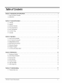 3
3
-
 4
4
-
 5
5
-
 6
6
-
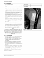 7
7
-
 8
8
-
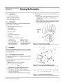 9
9
-
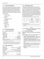 10
10
-
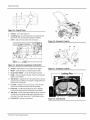 11
11
-
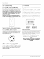 12
12
-
 13
13
-
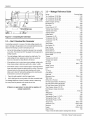 14
14
-
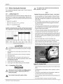 15
15
-
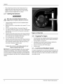 16
16
-
 17
17
-
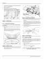 18
18
-
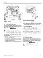 19
19
-
 20
20
-
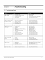 21
21
-
 22
22
-
 23
23
-
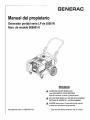 24
24
-
 25
25
-
 26
26
-
 27
27
-
 28
28
-
 29
29
-
 30
30
-
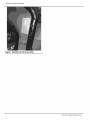 31
31
-
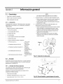 32
32
-
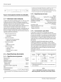 33
33
-
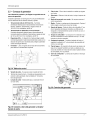 34
34
-
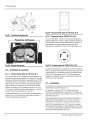 35
35
-
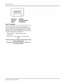 36
36
-
 37
37
-
 38
38
-
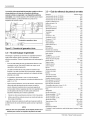 39
39
-
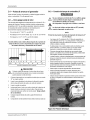 40
40
-
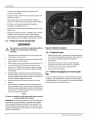 41
41
-
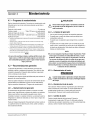 42
42
-
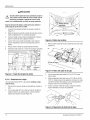 43
43
-
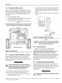 44
44
-
 45
45
-
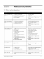 46
46
-
 47
47


Generac 006001-0 El manual del propietario
- Categoría
- Generadores de poder
- Tipo
- El manual del propietario
- Este manual también es adecuado para
En otros idiomas
- English: Generac 006001-0 Owner's manual