LG Electronics W182CA TSN0 Manual de usuario
- Tipo
- Manual de usuario

H
S
I
L
GNE
L
OÑ
A
PS
E
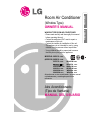
Room Air Conditioner
(Window Type)
OWNER'S MANUAL
WINDOW TYPE ROOM AIR CONDITIONER
• Please read carefully and thoroughly this manual
before operating this unit.
• Contact the authorized SVC man for repair or
maintenance of this unit.
• Contact the installer for installation of this unit.
• The appliance is not intended for use by young
children or infirm persons without supervision.
• Young children should be supervised to ensure
that they do not play with the appliance.
MODELS:
W091CATSG0
(MODELOS)
W092CATSG0
W121CATSC2
Antes de usar su aire acondionado, lea este manual
cuidadosamente y manténgalo para futura
referencia.
Aire Acondicionado
(Tipo de
Ventana)
MAN
UAL DEL USUARIO
W182CA TSN0
W182CM TSN0
W242CM TSN0
W242CA TSN0
W182CMH TSN1
W081CM TSG2
W242CM TSN2 W242CA TSN2
W242CA TSN4
W242CM TSN4

2
Window-Type Air Conditioner Owner’s Manual
TABLE OF CONTENTS
FOR YOUR RECORDS
Write the model and serial numbers here:
Model #
Serial #
You can find them on a label on the side of each unit.
Dealer's Name
Date Purchased
■ Staple your receipt to this page in the event you need
it to prove date of purchase or for warranty issues.
READ THIS MANUAL
Inside you will find many helpful hints on how to use
and maintain your air conditioner properly. Just a little
preventive care on your part can save you a great deal
of time and money over the life of your air conditioner.
You'll find many answers to common problems in the
chart of troubleshooting tips. If you review our chart of
Troubleshooting Tips first, you may not need to call
for service at all.
PRECAUTION
• Contact the authorized service technician for repair or
maintenance of this unit.
• Contact the installer for installation of this unit.
• The air conditioner is not intended for use by young
children or invalids without supervision.
• Young children should be supervised to ensure that
they do not play with the air conditioner.
• When the power cord is to be replaced, replacement
work shall be performed by authorized personnel only
using only genuine replacement parts.
• Installation work must be performed in accordance with
the National Electric Code by qualified and authorized
personnel only.
1. Safety Precautions
2. Operating Instructions
3. Care and Maintenance
4. Hardware Installation
5. Common Issues

Precautions
Safety
Precautions
3
ENGLISH
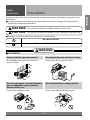
To prevent injury to the user or other people and property damage, the following instructions must
be followed.
■ Incorrect operation due to ignoring instruction will cause harm or damage. The seriousness is
classified by the following indications.
WARNING
CAUTION
This symbol indicates the possibility of death or serious injury.
This symbol indicates the possibility of injury or damage to properties only.
■ Meanings of symbols used in this manual are as shown below.
Be sure not to do.
Be sure to follow the instruction.
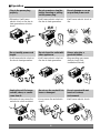
WARNING
■ Installation
Always install the expansion panel(s).
• No installation may cause fire and electric
shock accident.
Do not place the power cord near a heater.
• It may cause fire and electric shock.
Do not use the power cord near flammable
gas or combustibles such as gasoline,
benzene, thinner, etc.
• It may cause explosion or fire.
Do not disassemble or modify products.
• It may cause failure and electric shock.
Gasolin

4
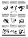
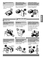
■ Operation
Plug in the power plug
properly.
• Otherwise, it will cause
electric shock or fire due to
heat generation or electric
shock.
Do not operate or stop the
unit by inserting or pulling
out the power plug.
• It will cause electric shock or
fire due to heat generation.
Do not damage or use an
unspecified power cord.
• It will cause electric shock or
fire.
Do not modify power cord
length.
• It will cause electric shock or
fire due to heat generation.
Do not share the outlet with
other appliances.
• It will cause electric shock or
fire due to heat generation.
Always plug into a
grounded outlet.
• No grounding may cause
electric shock (See
Installation Manual).
Unplug the unit if strange
sounds, odors, or smoke
come from it.
• Otherwise it may cause fire
and electric shock accident.
Do not use the socket if it is
loose or damaged.
• It may cause fire and electric
shock.
Do not operate with wet
hands or in damp
environment.
• It will cause electric shock.
ON

5
ENGLISH
Do not allow water to run
into electric parts.
• It will cause failure of machine
or electric shock.
Leave the door closed while
the air conditioner is
running.
• It is not designed to cool the
entire house.
Do not operate the air
conditioner if you smell gas.
• It may cause explosion, fire,
and burn.
Never touch the metal parts
of the unit when removing
the filter.
• They are sharp and may
cause injury.
Do not block the inlet or
outlet.
• It may cause failure of
appliance or accident.
Ensure that the outer case
is not damaged by age or
wear.
• If leaving appliance damaged,
there is concern of damage
due to the falling of product.
Be cautious not to touch the
sharp edges when
installing.
• It may cause injury.
Hold the plug by the head
when taking it out.
• It may cause electric shock
and damage.
Turn off the main power
switch when not using it for
a long time.
• Prevent accidental startup
and the possibility of injury.
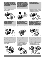
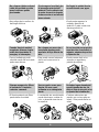
CAUTION
■ Installation
Sharp
edges
■ Operation

6
Do not place heavy object
on the power cord and take
care so that the cord should
not be pressed.
• There is danger of fire or
electric shock.
If water enters the product,
turn off the the power switch
of the main body of appliance.
Contact service center after
taking the power-plug out
from the socket.
Do not clean the air
conditioner with water.
• Water may enter the unit and
degrade the insulation. It may
cause an electric shock.
Turn off the power and
breaker firstly when
cleansing the unit.
• Since the fan rotates at high
speed during operation, it
may cause injury.
Do not put a pet or house
plant where it will be
exposed to direct air flow.
• This could injure the pet or
plant.
Do not use this appliance for
special purposes such as
cooling pets, foods, precision
machinery, or objects of art.
• It is an air conditioner, not a
precision refrigeration system.
Always insert the filter
securely.
Clean it every two weeks.
• Operation without filters will
cause failure.
Use a soft cloth to clean. Do
not use wax, thinner, or a
strong detergent.
• The appearance of the air
conditioner may deteriorate,
change color, or develop
surface flaws.
Do not drink water drained
from air conditioner. / Do
not direct airflow at room
occupants only.
• It contains containments and
will make you sick. / This
could damage your health.
Wax
Thinner

NOTICE
: Optional
7
H
S
I
L
G
NE
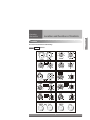
Location and Function of Controls
Operating
Instructions
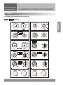
Controls
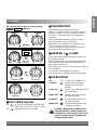
The controls will look like one of the following.
Controls

8
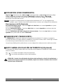
■ OPERATION
High Cool ( ), Med Cool ( ) and
Low Cool ( ) provide cooling with different fan speeds. Med Fan ( ) or Low Fan ( ) provides air
circulation and filtering without cooling. Off ( ) turns the air conditioner off.
: If you move the switch from a cool setting to off or to a fan setting, wait at least 3 minutes before
switching back to a cool setting.
Cooling Descriptions
For Normal Cooling- Select High Cool or Med Cool with the Operation knob at the midpoint of
Thermostat knob.
For Maximum Cooling- Select High Cool with the Operation knob at the highest number available on your
Thermostat knob.
For Quieter & Nighttime Cooling- Select Low Cool with the Operation knob at the midpoint of
Thermostat knob.
■ THERMOSTAT
The THERMOSTAT is used to maintain the room temperature. The compressor will cycle on and off to keep
the room at the same level of comfort. When you turn the knob to a higher number(the right side) and the
indoor air will become cooler.
The 5 or 6 position (the middle position of arc) is a normal setting for average conditions.
■ AUTO SWING (Optional)
Auto swing switch controls the horizontal air direction by air swing system (not on all models).
ON ( ) : Auto swing is operated.
OFF ( ) : Auto swing is not operated.
CAUTION: When the air conditioner has been performed its cooling operation and is turned off or
set to the fan position, wait at least 3 minutes before resetting to the cooling operation again.
NOTICE
o

Thermostat Operation
FAN FAN
Thermostat
Warmer Cooler
Heater
Operation
NOTICE
: Optional
9
ENGLISH
Controls
■
AUTO SWING (Optional)
ON ( ) :
Air swing is operated while OPERATION
knob is set to the COOL or HEAT position.
OFF( ) : Stops the operation of air swing.
■ THERMOSTAT
Turn the thermostat control to the desired
setting. The control position is a normal setting for
average conditions. You can change this setting, if
necessary, in accordance with your temperature
preference.
The thermostat automatically controls cooling or
heating, but the fan runs continuously
whenever the air conditioner is in operation. If the
room is too warm, turn the thermostat
control clockwise. If the room is too cool, turn the
thermostat control counterclockwise.
■ HEATER ( ) LAMP
When the unit sets heating operation condition, the
green lamp is lighted.
When the frost settles on the heat exchanger of the
outside, defrosting is made automatically and the
green lamp is turned off.
The unit may give a "hiss" and the fan motor stops for
1 to 10 minutes.
This should not be regarded as a problem.
After defrosting, the heating operation begins again.
■ OPERATION
OFF ( ) : Turns the air conditioner off.
LOW FAN ( ) : Permits the low fan speed
operation without cooling
(heating).
LOW COOL ( ) : Permits cooling with the low fan
speed operation.
HIGH COOL ( ) : Permits cooling with the high
fan speed operation.
LOW HEAT ( ) : Permits heating with the low
fan speed operation.
HIGH HEAT ( ) : Permits heating with the high
fan speed operation.
CAUTION : When the air conditioner has
been performed its cooling operation and
is turned off or set to the fan position, wait
at least 3 minutes before resetting to the
cooling operation again.
o
The controls will look like one of the following.

10
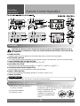
Remote Control Operation
Operating
Instructions
How to Insert the Batteries
CAUTION: The Remote Control unit will not function properly if strong light strikes the sensor
window of the air conditioner or it there are obstacles between the Remote Control unit and the
air conditioner.
1. POWER BUTTON
Operation starts, when this button is pressed and stops when you press the button again.
2. AUTO SWING (Optional)
The vertical louver swings horizontally by the automatic system and stops when you press the button again.
3. ROOM TEMPERATURE SETTING BUTTON
Control the room temperature within a range of 16°C to 30°C
4. FAN SPEED SELECTOR
Select the fan speed in three steps {High[F3] → Low[F1] → Med[F2] → High[F3]...}.
5. OPERATION MODE SELECTION BUTTON
Select Cooling, Fan, or Dehumidification mode with this button.
6. ON/OFF TIMER BUTTON
Set the time of starting and stopping operation. The timer is set by 1 hour.
7. SIGNAL RECEIVER
AUTO RESTART
In failure of electric power, the unit runs as previous setting operation.
1. Remove the cover from the back of
the remote controller.
2. Insert the two batteries.
3. Re-attach the cover.
• Do not use rechargeable batteries, such batteries differ from
standard dry cells in shape, dimensions, and performance.
• Remove the batteries from the
remote controller if the air
conditioner is not going to be
used for an extended length
of time.
Controls

VENTCLOSE OPEN
Part A
Part B
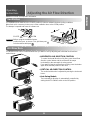
Adjusting the Air Flow Direction
Operating
Instructions
11
ENGLISH
Additional controls and important information.
Ventilation
Air Direction
The ventilation lever must be in the CLOSE position in order to maintain the best cooling conditions.
When fresh air is necessary in the room, set the ventilation lever to the OPEN position.
The damper is opened and room air is drawn out.
The direction of air can be controlled whenever you want to cool by adjusting the horizontal louver and the
vertical louver.
• HORIZONTAL AIR DIRECTION CONTROL
To control horizontal direction of air flow, press the air flow
direction control button and the air flow will be swept
horizontally by the automatic air-swing system.
If you want to stop the air flow from moving, press the button
again at the desired position of the vane.
• VERTICAL AIR-DIRECTION CONTROL
The vertical air direction is adjusted by moving the horizontal
louver.
• Auto Swing Models
The horizontal air direction is automatically controlled by
setting the AUTO SWING switch to the ON position.
:Before using the ventilation feature,
position the lever, as shown. First, pull down part
to horizontal line with part .
NOTICE

CABINET
DRAIN
PAN
DRAIN HOSE
SCREW
DRAIN PIPE
DRAIN HOSE
DRAIN PIPE
DRAIN ELBOW
DRAIN HOSE
Fig. 1
Fig. 2
12
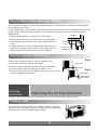
How to Attach Drain Pan (Some Models)
How to Connect a Drain Hose
The air conditioner employs a proper drain method whereby the condensed water (moisture removed from the
air) is drained to the outside.
In very humid weather, (and for reverse cycle models in the reverse mode) excessive condensate water removed
from the air may cause some water to collect. To remove this excess water you can install the drain pan as
detailed below.
1. Take the drain pan which is located in the air discharge.
2. Remove the hole rubber from the base-pan (for some models).
3. Install the drain pan to the right corner of the cabinet with 4 (or 2)
screws.
4. Connect the drain hose to the outlet located at the bottom of the
drain pan.You can purchase the drain hose or tubing locally to
satisfy your particular needs. (Drain hose is not supplied).
A drain hole is provided at the rear of the air conditioner unit.
Select a drain method according to the following.
1. Remove the hole rubber from the base-pan. (for some models)
2. Connect a drain hose to the drain pipe as shown in Fig. 1.
3. Or connect a pipe elbow to the drain pipe, then connect a drain hose
to the pipe elbow as shown in Fig. 2.
Outdoor Coils
The coils on the outdoor side of the air conditioner should be checked
regularly. If they are clogged with dirt or soot they may be professionally
steam cleaned, a service available through a dealer.
Adjusting the Air Flow Direction
Operating
Instructions
TURN THE AIR CONDITIONER OFF AND REMOVE THE PLUG FROM THE POWER OUTLET.

13
ENGLISH
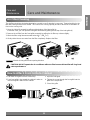
Air Filter Cleaning
How to Attach Front Grille to Cabinet
The air filter should be checked at least twice a month to see if cleaning is necessary. Trapped particles in the
filter will build up and block the airflow. This reduces the cooling capacity and also causes an accumulation of
frost on the cooling coils.
1. Open the inlet grille upward by pulling out the bottom of the inlet grille.(a)
In another case, you can open the inlet grille downward by pulling out the top of the inlet grille.(b)
2. Remove the air filter from the front grille assembly by pulling the air filter up or down slightly.
3. Wash the filter using lukewarm water below 40 C (104 F).(c)
4. Gently shake the excess water from the filter completely. Replace the filter.
CAUTION: DO NOT operate the air conditioner without a filter because dirt and lint will clog it and
reduce performance.
:Mark ∆ of inlet grille means opening direction.
NOTICE
1. Pull down front grille from the cabinet top.
2. Push front grille’s tips toward the cabinet in order to
insert front grille’s tabs into the cabinet.
3. Open the inlet grille.
4. Tighten the screw through the front grille into the
plate of the evaporator.
5. Close inlet grille.
Care and Maintenance
Care and
Maintenance

1 67 2 345
8
10 11 14
9
12 13
Screw
Foam
10
8 9
12 13 11 14
1 67 35 24
15
14
Hardware Installation
Hardware
Installation
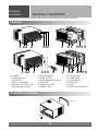
Learning parts name prior to installation will help you understanding the installation procedure.
Features
1. CABINET
2. HORIZONTAL AIR
DEFLECTOR
(VERTICAL LOUVER)
3. VERTICAL AIR DEFLECTOR
(HORIZONTAL LOUVER)
4. AIR DISCHARGE
5. FRONT GRILLE
6. AIR INTAKE(INLET GRILLE)
7. AIR FILTER
8. CONTROL BOARD
9. POWER CORD
10. EVAPORATOR
11. CONDENSER
12. COMPRESSOR
13. BASE PAN
14. BRACE
15. REMOTE CONTROLLER
Installation Hardware

White styrofoam block
10
~15 mm
Over 50 cm
HEAT
RADIATION
FENCE
AWNING
FOAM
COOLED
AIR
70-150cm
Level
1/4 Bubble
Shipping screws
Main Power source
Circuit Breaker
Use a circuit breaker
or time delay.
15
ENGLISH
Installation Steps
Hardware
Installation
Read completely, then follow step-by step.
• The appliance shall be installed in accordance with national wiring regulation.
• If a power plug isn't to be used, provide a circuit breaker between power source and the unit, as following
picture.
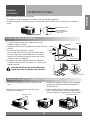
Select the Best Location
1. To prevent vibration and noise, make sure the unit is
installed securely and firmly.
2. Install the unit where the sunlight does not shine directly on
the unit.
3. There should be no obstacle, such as a
fence or wall, within 50cm from the back of the cabinet
because it will prevent heat radiation of the condenser.
Restriction of outside air will greatly reduce the cooling
efficiency of the air conditioner.
4. Install the unit a little obliquely outward not to leak the
condensed water into the room (about 10 ~ 15 mm or 1/4
bubble with level).
CAUTION: All side louvers of the cabinet must
remain exposed to the outside of the structure.
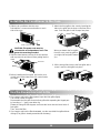
Remove the Air Conditioner From the Case
1. Remove the 2 shipping screws from the back of the
case.
2. Remove the 2 screws on each side of the case.
Keep these for later use.
3. Slide the air conditioner from the case by gripping
the base pan handle and pulling forward while
bracing the case.
4. Before installing the Air Conditioner back into the
case, remove the white styrofoam shipping block
from the compressor (Applicable for some models).

Power Cord
Screw
Screw
The Foam
16
Install the Air Conditioner in the Case
1. Slide the air conditioner into the case.
Reinstall the 2 screws removed earlier on each
side of the case.
CAUTION: The power cord must be
connected to an independent circuit. The
green wire must be grounded.
2. Stuff the foam between the top of the unit and the
wall to prevent air and insects from getting into the
room.
3. Before installing the front grille, pull out the vent
control lever located above the unit control knobs,
as shown.
5. Attach the front grille to the case by inserting the
tabs on the grille into the slots on the front of the
case. Push the grille in until it snaps into place.
6. Lift the inlet grill and secure the front grille with a
screw. Lower the inlet grille into place.
When you detach the front grille
from the case, push the grille to
your right side and pull it toward
you.
Use the Reversible Inlet Grille
1. If you want to pull out the filter upward, open the inlet grille slightly.
Turn inside out the front grille.
Disassemble the inlet grille from the front grille with separating the hinged part
by inserting a "—" type screw-driver tip.
Rotate the inlet grille 180 degrees and insert the hooks into the lower holes of
front grille.
Then, insert the filter
2. If you want to pull out the filter downward, use the reversible inlet grille without
change.(The grille is already assembled for that way.)

17
ENGLISH
Common Problems and Solutions
Common
Issues
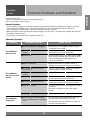
Troubleshooting Tips
Save time and money! Review the chart below first and
you may not need to call for service.
Normal Operation
• You may hear a pinging noise caused by water being picked up and thrown against the condenser on rainy
days or when the humidity is high. This design feature helps remove moisture and improve efficiency.
• You may hear the thermostat click when the compressor cycles on and off.
• Water will collect in the base pan during high humidity or on rainy days. The water may overflow and drip from
the outdoor side of the unit.
• The fan may run even when the compressor does not.
Abnormal Operation
Problem Possible Causes What To Do
■ The air conditioner is unplugged.
■ The fuse is blown/circuit breaker is
tripped.
■ Power failure.
■ Airflow is restricted.
■ The thermostat may not be set
high enough.
■ TEMP Control set too higher
number.
■ The air filter is dirty.
■ The room may have been hot.
■ Cold air is escaping.
■ Cooling coils have iced up.
■ Ice blocks the air flow and stops
the air conditioner from cooling the
room.
• Make sure the air conditioner plug is pushed
completely into the outlet.
• Check the house fuse/circuit breaker box and
replace the fuse or reset the breaker.
•
If power failure occurs, push power button to OFF.
When power is restored, wait 3 minutes to restart
the air conditioner to prevent tripping of the
compressor overload.
• Make sure there are no curtains, blinds, or
furniture blocking the front of the air conditioner.
• Turn the knob to a higher setting. The highest
setting provides maximum cooling.
• Set the TEMP control to a lower number.
• Clean the filter at least every 2 weeks.
See the operating instructions section.
• When the air conditioner is first turned on you
need to allow time for the room to cool down.
• Check for open furnace floor registers and cold
air returns.
• Set the air conditioner's vent to the closed
position.
• See Air Conditioner Freezing Up below.
• Set the mode control at MED fan or high cool
with the thermostat at 1 or 2 (Left side).
• Set the mode control at HIGH fan or high cool
with the high temperature.
Air conditioner
does not start
Air conditioner
does not cool as it
should
Air conditioner
freezing up

2
Manual del usuario del acondicionador de aire tipo Ventana
TABLA DE CONTENIDOS
PARA SUS ARCHIVOS
Escriba aquí el modelo y número de serie:
Modelo n°:
Serie n°:
Puede encontrar estos datos en la etiqueta situada en
el lateral de cada unidad.
Nombre del distribuidor:
Fecha de compra:
■
Adjunte su recibo a esta página con la grapadora para
el momento que lo necesite para probar la fecha de su
adquisición o para la validación de la garantía.
LEA ESTE MANUAL
En su interior encontrará muchos consejos útiles sobre la
utilización y mantenimiento de su acondicionador de aire.
Unos pocos cuidados por su parte le pueden ahorrar mucho
tiempo y dinero durante la vida de su acondicionador de aire.
En la tabla de consejos para la solución rápida de problemas
encontrará muchas respuestas a los problemas más
habituales. Si revisa primero nuestra Tabla de Consejos
para la solución rápida de problemas, tal vez no necesite
llamar nunca al servicio técnico.
PRECAUCIÓN
• Póngase en contacto con un técnico del servicio
autorizado para realizar la reparación y mantenimiento
de esta unidad.
• Póngase en contacto con un instalador para realizar la
instalación de esta unidad.
• Cuando se va a cambiar el cable eléctrico, el trabajo de
reemplazamiento debe ser realizado únicamente por
personal autorizado, utilizando las piezas de cambio
genuinas únicamente.
• El trabajo de reemplazamiento debe ser realizado de
acuerdo con el Código Eléctrico Nacional únicamente
por personal autorizado.
1. Precauciones de Seguridad
2. Instrucciones de Funcionamiento
3. Cuidados y Mantenimiento
4. Guía de Instalación del Equipo
5. Problemas Habituales

3
ESPAÑOL
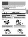
Precauciones
Precauciones de
Seguridad
Para prevenir tanto lesiones al usuario u otras personas como daños materiales, es preciso seguir
estas instrucciones.
■ El manejo incorrecto debido a la instrucción ignorada puede causar lesioes o daños cuya
gravedad está clasificada en als siguientes indicaciones.
ADVERTENCIA
PRECAUCION
Este símbolo indica la posibilidad de lesiones mortales o graves.
Este símbolo indica la posibilidad de lesiones o daños materi-ales.
■ El significado de los símbolos utilizados en este manual se indica a continuación.
Asegúrese de no hacerlo.
Asegúrese de seguir las instrucciones.
ADVERTENCIA
■ Instalación
Instale siempre el (los) panel(es) de
expansion.
• No instalarlo puede causar incendio y/o
accidente eléctrico.
No coloque el cable eléctrico cerca de un
calefactor.
• Puede causar incendio y descarga eléctrica.
No use el cable de corriente cerca de gas
inflamable o combustibles tales como
gasolina, benzina, solvente, etc.
• Puede causar explosión o incendio.
No desarme o modifique los productos.
• Puede causar fallos y descarga eléctrica.
Gasolin

4
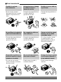
■ Funcionamiento
Enchufe la corriente
adecuadamente.
• De otro modo, causará
descarga eléctrica o incendio
debido a la generación de
calor.
No haga funcionar o detenga
la unidad insertando o
tirando del enchufe.
• Causará descarga eléctrica o
incendio debido a la
generación de calor.
No dañe ni use un cable no
especificado.
• Causará descarga eléctrica o
incendio.
No modifique la longitud del
cable de corriente eléctrica.
• Causará descarga eléctrica o
incendio debido a la
generación de calor.
No comparta la salida con
otros artefactos.
• Causará descarga eléctrica o
incendio debido a la
generación de calor.
Siempre enchufe las piezas
eléctricas en una salida
conectada a masa.
• Si no hay conexión a masa,
se puede producir una
descarga eléctrica. (Vea el
Manual de instalación.)
Desenchufe la unidad si se
producen sonidos u olores
extraños en la unidad.
• En caso que no, puede
causar incendio y accidente
de corto circuito.
No use el tomacorriente si
está suelto o dañado.
• Puede causar incendio y
accidente eléctrico.
No haga funcionar la unidad
con las manos húmedas o
en un ambiente húmedo.
• Puede causar descarga
eléctrica.
ON

5
ESPAÑOL
No permita la entrada de
agua.
• Puede causar una falla del
motor o una descarga
eléctrica.
Deje la puerta cerrada
mientras está operando el
aire acondicionado.
• Ésta no está diseñado para
enfriar la casa entera.
Ventile antes de hacer
funcionar el acondicionador
de aire cuando sale el gas.
• Puede causar explosión,
incendio, quemaduras.
Nunca toque las piezas de
metal de la unidad cuando
quite el filtro.
• Son filosas y pueden causar
lesiones.
No bloquee la entrada o la
salida de aire.
• Puede causar fallos en la
unidad o accidentes.
Asegúrese de que la caja
externa no está dañada por
los anõs o desgaste.
•
Si se deja la unidad averiada, hay
posibilidad de daños debido a
que esta puede caer. Hay
responsabilidad sobre el daño
debido a falla
del producto.
Al momento de su instalación,
evite que se contacte con los
bordes afilados.
• Hay riesgo de lesiones
personales.
Sostenga el enchufe por el
cuerpo (no del cable)
cuando lo saque.
• Puede causar descarga
eléctrica y daño.
Desconecte el interruptor
principal de energía cuando
no lo esté usando.
• Prevenga un arranque
accidental y la posibilidad de
lesiones.
PRECAUCION
■ Instalación
Bordes
afilados
■ Funcionamiento

6
No coloque objetos sobre el
cable de corriente y cuide
que el cable no quede
presionado.
• Hay peligro de incendio o de
descarga eléctrica.
Si entra agua a la unidad, gire
el interruptor principal del
artefacto. Tome contacto con
el centro de servicio después
de desconectar el enchufe del
tomacorriente.
No limpie la unidad de aire
acondicionado con agua.
• Puede entrar agua en la
unidad y disminuir la
aislación. Puede causar una
descarga eléctrica.
Cuando limpie la unidad,
asegúrese primero de que
estén desconectados la
energía y el interruptor.
•
Como el ventilador gira a alta
velocidad cuando está funcionando,
puede causar lesiones.
No coloque una mascota o
una planta donde quede
expuesto al flujo directo de
aire.
• Este puede causar lesiones o
daños en la mascota o la
planta.
No use la unidad para propósitos
especiales tales como animals o
vegetales, máquinas de precision
u objetos de arte.
• Puede causar daño a los
animales o vegetales y
pérdida de objetos.
Siempre asegure los filtros
al insertarlos. Límpielos
cada dos semanas.
• El funcionamiento sin filtros
puede dañar la unidad.
Use una paño suave para
limpiar. No use ceras,
solventes o un detergente
fuerte
•
La unidad del aire acondicionado
puede deteriorarse, cambiar de
color, o desarrollar manchas en
la superficie.
No beba el agua drenada del
acondicionador de aire. No
dirija el flujo de aire sólo a los
ocupantes de la habitación.
• Contiene elementos que
pueden ser nocivos para su
salud. / Esto puede dañar su
salud.
Wax
Thinner

7
L
O
Ñ
A
P
S
E
NOTA
: Opcional
Localización y Función de los Controles
Instrucciones de
Funcionamiento
Controles
Los controles serán como alguno de los siguientes.
Controls

8
■ OPERATION (FUNCIONAMIENTO)
High Cool (Enfriamiento Alto), Med Cool (Enfriamiento Medio) y Low Cool (Enfriamiento Bajo)
enfrían con distintas velocidades del ventilador. Med Fan (Ventilador Medio) o Low Fan
(Ventilador Bajo) proporcionan circulación del aire y filtrado sin enfriamiento. Off (Desactivado)
desconecta el acondicionador de aire.
:
Si cambia el conmutador desde una configuración de enfriamiento a OFF o a una configuración de
ventilador, espere 3 minutos como mínimo antes de volver a conectar a una configuración de enfriamiento.
Descripciones del Enfriamiento
Para una Enfriamiento normal – Seleccione High Cool o Med Cool con el mando Operation en el punto
medio del mando Thermostat.
Para una Enfriamiento máximo – Seleccione High Cool con el mando Operation en el número más alto
disponible en su mando Thermostat.
Para una Enfriamiento más suave y durante las horas nocturnas – Seleccione Low Cool con el mando
Operation en el punto medio del mando Thermostat.
■ THERMOSTAT (TERMOSTATO)
El THERMOSTAT se utiliza para mantener la temperatura de la habitación. El compresor se apagará y
encenderá de forma cíclica para mantener la habitación con el mismo nivel de confort. Cuando gire el mando
a un número mayor (hacia la derecha), el aire se hará más frío.
Las posiciones 5 o 6 (posición media del arco) es una configuración normal para unas condiciones medias.
■ AUTO SWING (OSCILACIÓN AUTOMÁTICA) (Opcional)
El interruptor Auto Swing controla la dirección horizontal del aire mediante un sistema de oscilación (no en
todos los modelos).
ON ( ): La oscilación automática está en funcionamiento
OFF ( ): la oscilación automática no está en funcionamiento
ATENCIÓN : Cuando el acondicionador de aire ha estado realizando su función de enfriamiento y
se desconecta o pasa a la posición de ventilador, espere como mínimo 3 minutos antes de volver
a ajustarlo para enfriamiento.
NOTA
o

9
ESPAÑOL
Thermostat Operation
FAN FAN
Thermostat
Warmer Cooler
Heater
Operation
NOTA
: Opcional
Controles
■
AUTO SWING (OSCILACIÓN
AUTOMÁTICA) (Opcional)
ON ( ) :
La oscilación del aire está en funcionamiento
mientras el mando OPERATION está en
posición COOL o HEAT.
OFF( ) : Detiene el funcionamiento de la oscilación
de aire.
■
THERMOSTAT (TERMOSTATO)
Gire el control del termostato a la configuración deseada. La
posición del control es una configuración normal para las
condiciones habituales. Si es necesario, puede cambiar esta
configuración según sus preferencias de temperatura.
El termostato controla automáticamente las funciones de
enfriamiento o calentamiento, pero el ventilador funciona
continuamente siempre que el acondicionador de aire esté
en marcha. Si la habitación está demasiado caliente, gire el
control del termostato en el sentido de las agujas del reloj; si
está demasiado fría, gírelo en sentido contrario.
■
LUZ HEATER (CALENTADOR)
Cuando la unidad está ajustada en una condición de
calentamiento se enciende la luz verde.
Cuando se acumula escarcha en el intercambiador térmico
del exterior, el desescarchado se realiza automáticamente y
la luz verde se apaga.
La unidad puede emitir un “silbido” y el motor del ventilador
se apaga entre 1 y 10 minutos.
Esta circunstancia no debe ser considerada un problema.
Tras el desescarchado, la operación de calentamiento
comienza de nuevo.
■
OPERATION (FUNCIONAMIENTO)
( ) :
Apaga el acondicionador de aire.
( ) : El ventilador funciona a baja
velocidad sin enfriamiento
(calentamiento).
( ) :
Enfriamiento con un funcionamiento
del ventilador a baja velocidad.
( ) :
Enfriamiento con un funcionamiento
del ventilador a alta velocidad.
( ) :
Calentamiento con un funcionamiento
del ventilador a baja velocidad.
( ) :
Calentamiento con un funcionamiento
del ventilador a alta velocidad.
ATENCIÓN: Cuando el acondicionador de aire ha
estado operando en enfriamiento y se desconecta
o se ajusta a una posición de ventilador, espere 3
minutos como mínimo antes de volver a ajustarlo
para enfriamiento.
o
Los controles serán como alguno de los siguientes.
OFF (APAGADO) :
LOW FAN
(VENTILADOR BAJO)
LOW COOL
(ENFRIAMIENTO BAJO)
HIGH COOL
(ENFRIAMIENTO ALTO)
LOW HEAT
(CALENTAMIENTO BAJO)
HIGH HEAT
(CALENTAMIENTO ALTO)

CONTROL REMOTO
10
Los controles tendrán el aspecto de los siguientes esquemas.
Controles
Como Insertar las Baterias Part que Opere el Control Remoto
ATENCIÓN : La unidad de Control Remoto no funcionará adecuadamente si la ventanilla del
sensor del acondicionador de aire recibe luz demasiado fuerte o si hay obstáculos entre la
unidad de Control Remoto y el acondicionador de aire.
AUTO-ARRANQUE
En caso de fallo de la corriente eléctrica, la unidad funcionará como antes cuando vuelve la corriente.
1. Remueva la tapa que se encuentra en la parte trasera
del control remoto en la dirección que indica la flecha.
2. Inserte 2 pilas esté seguro de colocarlas en la
polaridad que especifica en el dibujo grabado en el
control.
3. Deslice nuevamente la tapa como indica la flecha
para cerrar el compartimiento de las pilas.
• NO USE BATERIAS RECARGABLES
• CUANCO NO UTILICE EL CONTROL POR
PERIODOS LARGOS
NO DEJE LAS PILAS
EN EL INTERIOR
DEL CONTROL.
Operaciones del Mando a Distancia
Instrucciones de
Funcionamiento
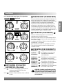
1. BOTON DE LA CORRIENTE
Se pone en marcha. Cuando este boton esta apretado, se detiene apretandolo de nuevo.
5. BOTON DE SELECCION DEL MODO OPERACIONAL
Seleccionar con este boton los modos para Refrescar, Ventilar y Deshumedecer.
6. BOTON ON/OFF TIMER
Ponga la hora de empezar y terminar el funcionamiento. El timer esta preajustado por una hora.(1-12Horas)
7. RECEPTOR DE SENAL
~~
4. SELECTOR DE LA VELOCIDAD DEL VENTILADOR
Seleccione la velocidad del ventilador en tres pasos [Alto(F3) Bajo(F1) Medio(F2) Alto(F3)...]
3. BOTON DE SELECCION DE LA TEMPER ATURA DE LA HABITACION
Controle la temperatura de la habitacion en una escala entre 16 C y 3 0 C
2. AUTO DEFLECTO (Opcional)
Las aletas se mueven verticalmente por un sistema automatico y se paran cuando presiona el boton otra vez.

Part A
Part B
VENTILACION
CERRAR ABRIR
VENTCLOSE OPEN
11
ESPAÑOL
Controles adicionales e informacion importante.
Ventilacion
Como controlar la direccion del aire
La palanca de ventilación deberá estar en la posición CLOSE (Cerrado) para poder mantener las mejores
condiciones de enfriamiento.
Cuando se necesite aire fresco en la habitación, coloque la palanca de ventilación en la posición OPEN (Abierto).
El amortiguador se abre y se descarga el aire de la habitación.
La dirección del aire frío puede ser controlada cuando usted lo desee ajustando los niveladores horizontales y
verticales.
• Control de Dirección del Aire Horizontal
La direccion de aire horizontal se ajusta moviendo el
nivelador vertical en dirección derecha o izquierda.
• Control de Dirección del Aire Vertical
La dirección de aire vertical es ajusta moviendo la rejila
horizontal.
• Modelos de Vuelta Automática
La dirección del aire horizontal es automáticamente
controlada ajustando el interruptor de VUELTA
AUTOMATICA a la posición de ENCENDIDO.
:Antes de usar la característica de ventilación, coloque la
palanca como se muestra. Primero jale hacia abajo la parte
para que quede en una línea horizontal con la parte .
NOTA
Ajuste de la Dirección del Flujo de Aire
Instrucciones de
Funcionamiento

Figura 1
Figura 2
CABINETE
CHAROLA
DE PURGA
MANGUERA
DE PURGA
TORNILLO
TUBO DE PURGA
MANGUERA DE PURGA
TUBO DE PURGA
CODO DE PURGA
MANGUERA
DE PURGA
12
Como colocar la charola de purga (Para algunos modelos)
Como conectar una manguera de purga
El aire acondicionado utiliza un método de purga adecuado en donde el agua condensada (humedad retirada del aire)
se purga al exterior.
En climas demasiado húmedos (y para modelos de ciclo invertido en la modalidad de inversión) el agua condensada
excesiva que se retira del aire puede ocasionar que se recolecte algo de agua. Para eliminar este exceso de agua,
puede instalar una charola de purga como se detalla a continuación.
1. Tome la charola de purga que se localiza en la descarga de aire o en la barrera.
2. Retire el orificio de hule de la charola de la base. (para algunos modelos).
3. Instale la charola de purga en el extermo izquierdo del gabinete con 4 (o 2)
tornillos.
4. Conecte la manguera de purga en la descarga localizada en el fondo de la
charola de purga. Puede adquirir la manguera o tubería de purga localmente
para satisfacer sus necesidades particulares (No se incluye la manguera de
purga).
Existe una manguera de purga incluida en la parte de atràs de la
unidad de aire acondicionado.
Elija un método de purga de acuerdo a lo siguiente.
1. Retire el orificio de hule de la charola de la base. (para algunos
modelos).
2. Conecte una manguera de purga al tubo de purga como se muestra
en la Figura 1.
3. Conecte un codo de tubo a la tubería de purga, después conecte
una manguera de purga al codo de tubo como se muestra en la
Figura 2.
Laminillas de la parte exterior
Los arrollamientos de la parte exterior del aire acondicionado deben ser
revisados regularmente. Si ellos están obstruidos con suciedad u hollín,
deben ser profesionalmente limpiados con vapor, un servicio disponible
a través de su proveedor.
APAGUE EL AIRE ACONDICIONADO Y SAQUE EL ENCHUFE DEL TOMA CORRIENTE DE LA PARED.
Ajuste de la Dirección del Flujo de Aire
Instrucciones de
Funcionamiento

ESPAÑOL
13
Limpieza del filtro de aire
Como instalar la parrilla delantera en el gabinete
El filtro de aire deberá revisarse cuando menos dos veces al mes para verificar si es necesario limpiarlo. Las
partículas atrapadas en el filtro podrían acumularse y bloquear el flujo de aire. Esto reduce la capacidad de
enfriamiento y también ocasiona la acumulación de escarcha en los serpentines de enfriamiento.
1. Abra la rejilla hacia arriba tirando la parte inferior de la rejilla de entrada (a). En otro caso, usted puede abrir
la rejilla de entrada hacia abajo tirando la parte superior de la rejilla de entrada.(b)
2. Retire el filtro de aire del ensamblaje de la parrilla delantera jalando el filtro de aire ligeramente hacia arriba.
3. Lave el filtro de aire usando agua tibia a menos de 40°C (104°F)
4. Sacuda suavemente el exceso de agua del filtro completamente. Vuelva a colocar el filtro.
PRECAUCION: NO OPERE el aire acondicionado sin filtro ya que la suciedad y las pelusas
obstruirán el filtro y se reducirá la eficiencia del funcionamiento.
:La marca ∆ de la rejilla de entrada significa la dirección abierta.
NOTA
1. Jale hacia abajo la parrilla delantera desde la parte
superior del gabinete.
2. Oprima las puntas de la parrilla delantera hacia el
gabinete para insertar las lengüetas de la parrilla
delantera en el gabinete.
3. Abra la parrilla de admisión.
4. Apriete el tornillo a través de la parrilla delantera
dentro en la placa de evaporador.
5. Cierre la parrilla de admisión.
Cuidados y Mantenimiento
Cuidados y
Mantenimiento

1 67 2 345
8
10 11 14
9
12 13
Tornillo
Espuma
10
8 9
12 13 11 14
1 67 35 24
15
14
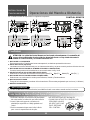
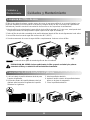
Conocer el nombre de las partes antes de instalar el aire, lo ayudará a entender mejor el proceso de instalación.
Características
1. GABINETE
2. DEFLECTOR DE AIRE
HORIZONTAL (REJILLA
VERTICAL)
3. DEFLECTOR DE AIRE
VERTICAL (REJILLA
HORIZONTAL)
4. DESCARGA DE AIRE
5. REJILLA FRONTAL
6. ENTRADA DE AIRE
(REJILLA PARA ENTRADA)
7. FILTRO DE AIRE
8. PANEL DE CONTROL
9. CABLE DE ALIMENTACION
10. EVAPORADOR
11. CONDENSADOR
12. COMPRESOR
13. PLATO DE BASE
14. ABRAZADERA
15. CONTROL REMOTO
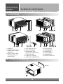
Accesorios de Instalación
Instalación del Equipo
Guía de Instalación
del Equipo

ESPAÑOL
Bloque de Unicel Blanco
10
-15 mm
Más de 50 cm
Radiación
de calor
Cerca
Toldo
Espuma
Aire enfriado
70-150cm
Nivel
1/4 Ampolla
Tornillos
Fuente de energía principal
Cortacircuitos
Utilice un interruptor térmico
un cortacircuitos de o espoleta
de retardo.
15
Lea completamente y siga paso a paso.
• El aparato será instalado de acuerdo con las regulaciones de cableado del país.
• Si no usa un enchufe de alimentación, proporcione un cortacircuitos entre la fuente de energía y la unidad
como la siguiente figura.
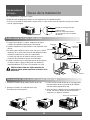
Seleccione la mejor ubicación
1. Para prevenir vibración y ruidos, asegúrese de que la
unidad sea instalada seguramente y firmemente.
2. Instale la unidad en un lugar donde no sea expuesta al sol
directo.
3. No debe haber obstáculos tales como una cerca o pared,
dentro de 50 cm de la parte posterior del gabinete porque
obstruiría la radiación de calor del condensador.
La restricción del aire del exterior reducirá mucho la
eficiencia del enfriamiento del aire acondicionado.
4. Instale la unidad un poco oblicuamente hacia afuera para
no dejar escapar el agua condensado a la habitación
(aproximadamente 10-15 mm o 1/4 ampolla con nivel).
PRECAUCION: Todas las rejillas laterales del
gabinete deben quedar expuestas al exterior de la
estructura.
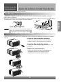
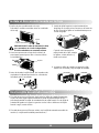
Remueva el aire acondicionado de la caja
1. Remueva 2 tornillos de la parte posterior de la caja.
2. Remueva 2 tornillos en cada lado de la caja.
Guárdelos para usar después.
3. Deslice el aire acondicionado de la caja agarrando
la asa del plato de base y tirando hacia adelante
mientras está asegurando la caja.
4. Antes de volver a instalar el aire acondicionado en
la caja, remueva el bloque de unicel blanco del
compresor (en algunos modelos).
Pasos de la Instalación
Guía de Instalación
del Equipo

Cable de alimentación
Tornillo
Tornillo
Espuma
16
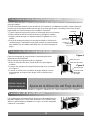
Instale el Aire acondicionado en la Caja
1. Deslice el aire acondicionado a la caja.
Reinstale 2 tornillos removidos antes en cada lado
de la caja.
PRECAUCION: El cable de alimentación debe
ser conectado a un circuito independiente.
El cable verde debe ser conectado a tierra.
2. Llene la espuma entre el tope de la unidad y la
pared para prevenir que el aire e insectos entren
en la habitación.
3. Antes de instalar la rejilla frontal, tire la palanca de
respiradero localizada encima de los controles de
la unidad como lo enseñado.
5. Instale la rejilla frontal a la caja insertando las
lengüetas en la rejilla en las ranuras en el frente de
la caja. Empuje la rejilla en la unidad hasta que se
cierren de golpe.
6. Levante la rejilla de entrada y asegure la rejilla
frontal con un tornillo y baje la rejilla de entrada.
Cuando usted despegue la
rejilla frontal de la caja, empuje
la rejilla a su lado derecho y
tírela hacia usted.
Use la rejilla de entrada reversible
1. Si usted desea sacar el filtro por abajo, abra la rejilla de entrada ligeramente.
Separe la parte enganchada insertando la punta del destornillador de tipo “–”
para desensamblar la rejilla de entrada desde la rejilla frontal. Gire la rejilla de
entrada 180 grados e inserte los ganchos en los huecos inferiores del rejilla
frontal. Luego, inserte el filtro.
2. Si usted desea sacar el filtro por arriba, use la rejilla de entrada reversible sin
cambio. (La rejilla está instalada para tal efecto.)

ESPAÑOL
17
Problemas Habituales y Soluciones
Problemas
Habituales
Tips para la resolución de problemas
¡Ahorre tanto el tiempo como el dinero!
Si revisa el siguiente cuadro primero, seguramente usted no necesitará llamar al servicio técnico
frecuentemente.
Operación Normal
• Usted puede oir ruido agudo por el impacto causado por el agua que es recogida y lanzada contra el
condensador cuando llueve o hay humedad muy alta. Esta característica de diseño ayuda a remover la
humedad y mejorar la eficiencia.
• Usted puede oir el sonido de golpe del termostato cuando el compresor pase por el ciclo de encendido y de
apagado.
• El agua se colectará en el plato de base cuando llueva o haya alta humedad. El agua puede rebosar y gotear
de la parte exterior de la unidad.
• El ventilador puede operar aun cuando el compresor no opere.
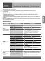
Operación Anormal
Problema Posibles causas Qué hacer
■ El aire acondicionado está
desconectado.
■ El fusible está fundido/ El cortacircuitos
está disparado.
■ Falla de alimentación
■ La corriente de aire está obstruida.
■ No se ajusto el TERMOSTATO en el
nivel adecuado (suficientemente alto)
■ Coloque el control de TEMPERATURA
en un número más alto.
■ El filtro de aire está sucio.
■ La habitación pudo haber estado
demasiado caliente.
■ El aire frío está escapando.
■ Se congelaron las laminillas de
enfriamiento.
■ El hielo obstruye la corriente de aire e
impide que el aire acondicionado enfríe
adecuadamente la habitación.
• Asegúrese de que el enchufe del aire acondicionado
sea insertado completamente en la toma.
• Cheque el fusible/ caja de cortacircuitos y reemplace el
fusible o reajuste el cortacircuitos.
• Si la falla de alimentación ocurre, posicione el control
de modo a APAGADO. Cuando la energía sea
restaurada, espere 3 minutos para reiniciar el aire
acondicionado para prevenir la sobrecarga del
compresor.
• Asegúrese de que no exista ni cortinas, ni persianas ni
muebles bloqueando el frente del aire acondicionado.
• Gire el botón a un número más alto. El ajuste más alto
proporciona el enfriamiento máximo.
• Gire el control de TEMPERATURA a un número más
bajo.
• Limpie el filtro por lo menos cada 2 semanas. Vea la
sección de las instrucciones de operación.
• Cuando el aire acondicionado sea encendido, usted
debe esperar por un tiempo hasta que la habitación se
ponga fresca.
• Revise si está abierto el control de piso de calefacción
y el aire frío regresa.
• Ajuste el respiradero del aire acondicionado a la
posición cerrada.
• Vea “El aire acondicionado congela” abajo.
• Ajuste el control de modo en Ventilación Mediana o
Enfriamiento Alto con el termóstato en 1 o 2
(El lado
izquierdo).
• Ajustar el control de modo en ‘Ventilación alta’ o
‘Erfriamiento alto’ con la temperatura alta.
El aire
acondicionado no
pone en marcha.
El aire
acondicionado no
enfria como se
debe.
El aire
acondicionado
congela.

Fuente de corriente
• MOD
ELO: W121CA
TSC2
/W091CA
TSG0/W081CM TSG2
Esta unidad requiere una alimentación eléctrica monofásica con hilo a tierra con un voltaje de
115 Vca / 60 Hz de corriente alterna.
Esta unidad requiere una alimentación eléctrica monofásica con hilo a tierra con un voltaje de
220 Vca / 60 Hz de corriente alterna.
18
• MODELO: W122CA
TSC0
/W092CA
TSG0/W182CMH TSN1/W182CA TSN0
Instalación (para 60 Hz)
• Requisitos de la instalación eléctrica para seguridad personal:
• Este aparato deberá conectarse debidamente a tierra.
• No corte ni elimine en ninguna circunstancia la terecera espiga del cordón eléctrico.
• Recomendamos que no utilice cordón de extensión o adaptador con este aparato.
• Siga los códigos eléctricos nacionales o los códigos y ordenanzas locales.
• Si el suministro de corriente eléctrica no cumple las especificaciones antes
mencionadas llame a un electricista autoriazdo.
• El cableado de aluminio de las casas puede plantear problemas especiales consulte
con electricista autorizado.
• Esta unidad requiere de un circuito separado, que sirva sólo para esta aplicación.
Fabricante
(Oficina) LG Electronics Inc., LG Twin Towers, 20, Yoido-dong, Youngdungpo-gu,
Seúl 150-606, Corea Tel: 82-2-3777-7974
(Fábrica) LG Changwon 2nd fábrica, 76, Seong San Dong, Changwoncity,
Gyeong Nam, 641-713, Corea Tel: 82-55-269-3480
Importador
LG Electronics México S.A de C.V. Av. Sor Juana Ines de la Cruz No 555. Col. San Lorenzo,
Tlalnepantla, Edo de Mex. Tel: 5321 1900
W182CM TSN0/W242CA
TSN0
/W242CM
TSN0/W242CM TSN2
W242CA TSN2/W242CA TSN4/W242CM TSN4

Nota
19
ESPAÑOL

P/No.: MFL57207002 Printed in China
After reading this manual, keep it in a place easily accessible to the user for future reference.
-
 1
1
-
 2
2
-
 3
3
-
 4
4
-
 5
5
-
 6
6
-
 7
7
-
 8
8
-
 9
9
-
 10
10
-
 11
11
-
 12
12
-
 13
13
-
 14
14
-
 15
15
-
 16
16
-
 17
17
-
 18
18
-
 19
19
-
 20
20
-
 21
21
-
 22
22
-
 23
23
-
 24
24
-
 25
25
-
 26
26
-
 27
27
-
 28
28
-
 29
29
-
 30
30
-
 31
31
-
 32
32
-
 33
33
-
 34
34
-
 35
35
-
 36
36


