Kichler Lighting 10766WHLED Manual de usuario
- Tipo
- Manual de usuario

Date Issued: 05/18/17
IS-10766LED-US
We’re here to help 866-558-5706
Hrs: M-F 9am to 5pm EST
WARNING:
• This fixture is intended for installation in accordance with the National Electric Code
(NEC) and all local code specifications.
• Supply wires are not intended for use through or concealed behind walls, floors, or
ceilings.
CAUTION – RISK OF SHOCK – Disconnect Power at the main circuit breaker panel or
main fuse box before starting and during the installation.
1) Read and understand all instructions and illustrations completely before proceeding
with assembly and installation of fixture.
2) If you have any doubts about how to install this fixture, or if the fixture fails to
operate completely, please contact a qualified electrician.
3) All parts must be used as indicated in the instructions. Do not substitute any parts,
leave parts out, or use any parts that are worn or broken. Failure to obey this instruction
could invalidate the UL listing, C.S.A. certification, and/or ETL listing of this fixture.
4) Fixture is to be connected to a single branch circuit.
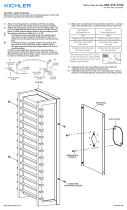
5) Mounting surface should be clean, dry, flat and 1/4” larger than the fixture housing
surface.
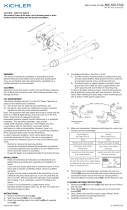
6) Remove lens. Twist diffuser counterclockwise to remove it from the fixture. Set
aside. DO NOT touch LEDs with hands or fingers.
7) Install (2) two mounting screws into the outlet box, leaving small amount of threads
exposed.
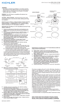
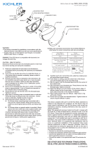
8) Grounding instructions: (See Illus. A or B).
A) On fixtures where mounting strap is provided with a hole and two raise dimples.
Wrap ground wire from outlet box around green ground screw, and thread into
hole.
B) On fixtures where a cupped washer is provided. Put ground wire from outlet box
under cupped washer and green ground screw and thread screw into hole in
mounting strap.
If fixture is provided with ground wire. Connect fixture ground wire to outlet box
ground wire with wire connector, (not provided) after following the above steps. Never
connect ground wire to black or white power supply wires.
9) Make wire connections. Reference chart below for correct connections and wire
accordingly.
10) Carefully push wire connections back into outlet box making sure all connections
remain secure.
11) Push fixture over outlet box and align the larger hole side of keyhole slot with
screws in outlet box. Push fixture to ceiling and turn fixture in direction of smaller
side of keyhole slots until it stops. Tighten strap mounting screws to secure.
12) Place diffuser up to canopy and align the open sections of diffuser slots. Push
diffuser up to backplate and twist clockwise to lock in place.
GREEN GROUND
SCREW
CUPPED
WASHER
OUTLET BOX
GROUND
FIXTURE
GROUND
DIMPLES
WIRE CONNECTOR
OUTLET BOX
GROUND
GREEN GROUND
SCREW
FIXTURE
GROUND
A
B
Connect Black or
Red Supply Wire to:
Connect
White Supply Wire to:
Black White
*Parallel cord (round & smooth) *Parallel cord (square & ridged)
Clear, Brown, Gold or Black
without tracer
Clear, Brown, Gold or Black
with tracer
Insulated wire (other than green)
with copper conductor
Insulated wire (other than green)
with silver conductor
*Note: When parallel wires (SPT I & SPT II)
are used. The neutral wire is square shaped
or ridged and the other wire will be round in
shape or smooth (see illus.)
Neutral Wire
This device complies with part 15 of the FCC Rules. Operation is subject to the following
two conditions: (1) This device may not cause harmful interference, and (2) this device
must accept any interference received, including interference that may cause undesired
operation.
Note: This equipment has been tested and found to comply with the limits for a Class B
digital device, pursuant to part 15 of the FCC Rules. These limits are designed to pro-
vide reasonable protection against harmful interference in a residential installation. This
equipment generates, uses and can radiate radio frequency energy and, if not installed
and used in accordance with the instructions, may cause harmful interference to radio
communications. However, there is no guarantee that interference will not occur in a par-
ticular installation. If this equipment does cause harmful interference to radio or television
reception, which can be determined by turning the equipment off and on, the user is
encouraged to try to correct the interference by one or more of the following measures:
• Reorient or relocate the receiving antenna.
• Increase the separation between the equipment and receiver.
• Connect the equipment into an outlet on a circuit different from that to which the receiver
is connected.
• Consult the dealer or an experienced radio/TV technician for help.
SEE OTHER SIDE FOR SPANISH TRANSLATIONS.
VEA EL OTRO LADO DE TRADUCCIONES AL ESPAÑOL.
OUTLET BOX
WIRE
CONNECTORS
CANOPY
DIFFUSER
MOUNTING SCREWS
INSTALLATION INSTRUCTIONS
Model 10766LED / CP159837
Model 10767LED / CP159838
Model 10768LED / CP159839

Date Issued: 05/18/17
IS-10766LED-US
We’re here to help 866-558-5706
Hrs: M-F 9am to 5pm EST
AVERTISSEMENT:
• Ce luminaire doit être installé conformément aux codes d’électricité nationaux (NEC) et
satisfaire toutes les spécifications des codes locaux.
• Les câbles d’alimentation ne doivent pas être utilisés à travers ou derrière des parois,
sols ou plafonds.
PRECAUCIÓN – RIESGO DE DESCARGA ELÉCTRICA – Desconecte la electricidad en el
panel principal del interruptor automático o caja principal de fusibles antes de comenzar
y durante la instalación.
1) Lire et comprendre toutes les instructions et illustrations avant de procéder au
montage et à l’installation du luminaire.
2) En cas de doute sur l’installation de ce luminaire, ou si le luminaire ne fonctionne
pas correctement, prière de contacter un électricien agréé.
3) Utiliser toutes les pièces selon les instructions. Ne pas substituer de pièces, exclure
certaines pièces du montage ou se servir de pièces usées ou endommagées. Le
non-respect de ces instructions risque d’annuler l’homologation UL, le certificat
C.S.A. ainsi que l’homologation ETL de ce luminaire.
4) Le luminaire peut être connecté à un circuit dédié.
5) La superficie de montaje debe estar limpia, seca y plana, y ser ¼ de pulgada más
grande que la superficie de la cubierta del artefacto.
6) Saque el lente. Gire el difusor hacia la izquierda para sacarlo del artefacto. Déjelo a
un lado. NO toque los LEDs con las manos o los dedos.
7) Instale (2) dos tornillos de montaje en la caja de salida, dejando una pequeña
cantidad de roscas expuestas.
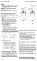
8) Instrucciones de puesta a tierra: (Vea la ilustración A o B)
A) En los artefactos donde se proporciona la abrazadera de montaje con un
agujero y dos depresiones elevadas. Envuelva el alambre a tierra de la caja de
salida alrededor del tornillo a tierra verde y rosque el tornillo en el agujero.
B) En los artefactor donde se proporciona una arandela cóncava. Ponga el
alambre a tierra de la caja de salida entre la arandela cóncava y el tornillo a
tierra verde y rosque el tornillo en el agujero, en la abrazadera de montaje.
Si se proporciona el artefacto con alambre a tierra, conecte el alambre a tierra del
artefacto al alambrea a tierra de la caja de salida, con el conector de alambre (no propor-
cionado), después de seguir los pasos de arriba. Nunca conecte el alambre a
tierra a los alambres blanco o negro de la alimentación eléctrica.
9) Hacer las conexiones de los alambres (conectores no incluidos.) Ver el cuadro más
abajo para las conexiones correctas y alambrar de acuerdo a esto.
10) Empuje cuidadosamente las conexiones de cables dentro de la caja de salida,
asegurándose de que todas las conexiones queden firmes.
11) Empuje el artefacto sobre la caja de salida y alinee el lado del agujero grande de la
muesca de bocallave con los tornillos en la caja de salida. Empuje el artefacto al
techo y gire el artefacto en dirección del lado más pequeño de las muescas de
bocallave hasta que se detenga. Apriete los tornillos de montaje de la abrazadera
para asegurar.
12) Coloque el difusor hasta el escudete y alinee las secciones abiertas de las muescas
del difusor. Empuje el difusor hasta la bandeja trasera y gire hacia la derecha para
asegurar en su lugar.
ARANDELA
CONCAVA
TIERRA DE LA
CAJA DE SALIDA
TORNILLO DE TIERRA,
VERDE
DEPRESIONES
TIERRA
ARTEFACTO
CONECTOR DE ALAMBRE
TIERRA DE LA
CAJA DE SALIDA
TORNILLO DE TIERRA,
VERDE
TIERRA
ARTEFACTO
A
B
Conectar el alambre de
suministro negro o rojo al
Conectar el alambre de
suministro blanco al
Negro Blanco
*Cordon paralelo (redondo y liso)
*Cordon paralelo (cuadrado y estriado)
Claro, marrón, amarillio o negro
sin hebra identificadora
Claro, marrón, amarillio o negro
con hebra identificadora
Alambre aislado (diferente del verde)
con conductor de cobre
Alambre aislado (diferente del
verde) con conductor de plata
*Nota: Cuando se utiliza alambre paralelo
(SPT I y SPT II). El alambre neutro es de forma
cuadrada o estriada y el otro alambre será de
forma redonda o lisa. (Vea la ilustracíón).
Hilo Neutral
Este artefacto cumple con la parte 15 de las Normas de la FCC. El funcionamiento está
sujeto a las siguientes dos condiciones: (1) Este artefacto no puede causar interferencia
perjudicial, y (2) este artefacto debe aceptar cualquier interferencia recibida, inclusive
interferencia que puede causar una operación no deseada.
Nota: Este equipo ha sido probado y se comprobó que cumple con los límites para un
artefacto digital Clase B, de conformidad con la parte 15 de las Normas de la FCC. Estos
límites están diseñados para proporcionar una protección razonable contra interferencia
perjudicial en una instalación residencial. Este equipo genera, usa y puede radiar energía
de radio frecuencia y, si no se instala y usa de acuerdo con las instrucciones, puede cau-
sar interferencia perjudicial las comunicaciones de radio. Sin embargo, no hay garantía
que la interferencia no ocurrirá en una instalación en particular. Si este equipo sí causa
interferencia perjudicial a la recepción de radio o televisión, que puede ser determinado
enciendo y apagando el equipo, se alienta al usuario a que trata de corregir la interferen-
cia con una o más de las siguientes medidas:
• Reoriente o cambie de lugar la antena de recepción.
• Aumente la separación entre el equipo y el receptor.
• Conecte el equipo en un receptáculo en un circuito diferente de donde está conectado
el receptor.
• Consulte al distribuidor o a un técnico de radio/TV experimentado para ayuda.
SEE OTHER SIDE FOR ENGLISH TRANSLATIONS.
VEA EL OTRO LADO DE TRADUCCIONES AL INGLÉS.
CAJA DE SALIDA
CONECTORES DE ALAMBRE
ESCUDETE
DIFUSOR
TORNILLO DE MONTAJE
INSTRUCCIONES DE INSTALACIÓN
Modelo 10766LED / CP159837
Modelo 10767LED / CP159838
Modelo 10768LED / CP159839

Date Issued: 05/18/17
IS-10766LED-CB
We’re here to help 866-558-5706
Hrs: M-F 9am to 5pm EST
WARNING:
• This fixture is intended for installation in accordance with the National Electric Code
(NEC) and all local code specifications.
• Supply wires are not intended for use through or concealed behind walls, floors, or
ceilings.
CAUTION – RISK OF SHOCK – Disconnect Power at the main circuit breaker panel or
main fuse box before starting and during the installation.
1) Read and understand all instructions and illustrations completely before proceeding
with assembly and installation of fixture.
2) If you have any doubts about how to install this fixture, or if the fixture fails to
operate completely, please contact a qualified electrician.
3) All parts must be used as indicated in the instructions. Do not substitute any parts,
leave parts out, or use any parts that are worn or broken. Failure to obey this instruction
could invalidate the UL listing, C.S.A. certification, and/or ETL listing of this fixture.
4) Fixture is to be connected to a single branch circuit.
5) Mounting surface should be clean, dry, flat and 1/4” larger than the fixture housing
surface.
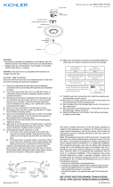
6) Remove lens. Twist diffuser counterclockwise to remove it from the fixture. Set
aside. DO NOT touch LEDs with hands or fingers.
7) Install (2) two mounting screws into the outlet box, leaving small amount of threads
exposed.
8) Make wire connections. Reference chart below for correct connections and wire
accordingly.
9) Carefully push wire connections back into outlet box making sure all connections
remain secure.
10) Push fixture over outlet box and align the larger hole side of keyhole slot with
screws in outlet box. Push fixture to ceiling and turn fixture in direction of smaller
side of keyhole slots until it stops. Tighten strap mounting screws to secure.
11) Place diffuser up to canopy and align the open sections of diffuser slots. Push
diffuser up to backplate and twist clockwise to lock in place.
Connect Black or
Red Supply Wire to:
Connect
White Supply Wire to:
Black White
*Parallel cord (round & smooth)
*Parallel cord (square & ridged)
Clear, Brown, Gold or Black
without tracer
Clear, Brown, Gold or Black
with tracer
Insulated wire (other than green)
with copper conductor
Insulated wire (other than green)
with silver conductor
*Note: When parallel wires (SPT I & SPT II)
are used. The neutral wire is square shaped
or ridged and the other wire will be round in
shape or smooth (see illus.)
Neutral Wire
This device complies with part 15 of the FCC Rules. Operation is subject to the following
two conditions: (1) This device may not cause harmful interference, and (2) this device
must accept any interference received, including interference that may cause undesired
operation.
Note: This equipment has been tested and found to comply with the limits for a Class B
digital device, pursuant to part 15 of the FCC Rules. These limits are designed to pro-
vide reasonable protection against harmful interference in a residential installation. This
equipment generates, uses and can radiate radio frequency energy and, if not installed
and used in accordance with the instructions, may cause harmful interference to radio
communications. However, there is no guarantee that interference will not occur in a par-
ticular installation. If this equipment does cause harmful interference to radio or television
reception, which can be determined by turning the equipment off and on, the user is
encouraged to try to correct the interference by one or more of the following measures:
• Reorient or relocate the receiving antenna.
• Increase the separation between the equipment and receiver.
• Connect the equipment into an outlet on a circuit different from that to which the receiver
is connected.
• Consult the dealer or an experienced radio/TV technician for help.
OUTLET BOX
WIRE
CONNECTORS
CANOPY
DIFFUSER
MOUNTING SCREWS
SEE OTHER SIDE FOR CANADIAN FRENCH TRANSLATIONS.
VOIR L’AUTRE CÔTÉ POUR LES CANADIENS TRADUCTIONS
EN FRANÇAIS.
INSTALLATION INSTRUCTIONS
Model 10766LED / CP159837
Model 10767LED / CP159838
Model 10768LED / CP159839
INSTRUCTIONS
For Assembling and Installing Fixtures in Canada
Pour L’assemblage et L’installation Au Canada

Date Issued: 05/18/17
IS-10766LED-US
We’re here to help 866-558-5706
Hrs: M-F 9am to 5pm EST
INSTRUCTIONS D’INSTALLATION
Model 10766LED / CP159837
Model 10767LED / CP159838
Model 10768LED / CP159839
SEE OTHER SIDE FOR ENGLISH TRANSLATIONS.
VOIR L’AUTRE COTE DES TRADUCTIONS EN ANGLAIS.
Cet appareil est conforme à la section 15 de la réglementation de la FCC. L’exploitation
est soumise aux deux conditions suivantes : (1) Cet équipement ne doit pas causer d’in-
terférences nuisibles, et (2) cet équipement doit accepter toute interférence reçue, y com-
pris les interférences risquant d’engendrer un fonctionnement indésirable.
Remarque: Des tests ont confirmé que ce matériel respecte les limites d’un dispositif
numérique de catégorie B, en vertu de la section 15 de la réglementation de la FCC.
Ces limites ont été conçues pour fournir une protection raisonnable contre le brouillage
nuisible d’une installation résidentielle. Cet équipement génère, utilise et peut rayonner
de l’énergie radiofréquence et, s’il n’est pas installé et utilisé selon les instructions, peut
causer de l’interférence nuisible aux communications de radio. Cependant, il est néan-
moins possible qu’il y ait de l’interférence dans une installation en particulier. Si cet équi-
pement cause du brouillage nuisible à la réception du signal de radio ou de télévision, ce
qui peut être déterminé en éteignant puis en rallumant l’appareil, l’usager peut essayer de
corriger l’interférence en appliquant une des mesures suivantes :
• Réorienter l’antenne de réception ou changer son emplacement.
• Augmenter la distance séparant l’équipement et le récepteur.
• Brancher le matériel dans la prise de courant d’un circuit différent de celui auquel le
récepteur est branché.
• Consulter le revendeur ou un technicien radio/télé d’expérience.
AVERTISSEMENT:
• Ce luminaire doit être installé conformément aux codes d’électricité nationaux (NEC) et
satisfaire toutes les spécifications des codes locaux.
• Les câbles d’alimentation ne doivent pas être utilisés à travers ou derrière des parois,
sols ou plafonds.
ATTENTION – RISQUE DE DÉCHARGES ÉLECTRIQUES – Couper le courant au niveau
du panneau du disjoncteur du circuit principal ou de la boîte à fusibles principale
avant de procéder à l’installation.
1) Lire et comprendre toutes les instructions et illustrations avant de procéder au
montage et à l’installation du luminaire.
2) En cas de doute sur l’installation de ce luminaire, ou si le luminaire ne fonctionne pas
correctement, prière de contacter un électricien agréé.
3) Utiliser toutes les pièces selon les instructions. Ne pas substituer de pièces, exclure
certaines pièces du montage ou se servir de pièces usées ou endommagées. Le
non-respect de ces instructions risque d’annuler l’homologation UL, le certificat
C.S.A. ainsi que l’homologation ETL de ce luminaire.
4) Le luminaire peut être connecté à un circuit dédié.
5) La surface de montage doit être propre, sèche, plate et plus grande de 0,6 cm que
la surface du boîtier du luminaire.
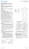
6) Retirer les lentilles. Tourner le diffuseur dans le sens antihoraire pour le retirer du
luminaire. Mettre de côté. NE PAS toucher les diodes LED avec les mains ou les
doigts.
7) Insérer deux (2) vis de l’étrier de montage dans la boîte de sortie en exposant un
peu des filets.
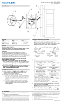
8) Connecter les fils (connecteurs non fournis). Se reporter au tableau ci-dessous pour
faire les connexions.
9) Replacer soigneusement les fils dans la boîte à prises en veillant à ce que les
conexions ne soient pas déconnectées.
10) Pousser le luminaire par dessus la boîte de sortie, aligner le côté de la trou plus
grande de la fente en trou de serrure avec des vis dans la boîte de sortie. Pousser
le luminaire vers le plafond et le tourner dans le sens du plus petit côté de fentes en
trou de serrure jusqu’au blocage. Serrer les vis de l’étrier de montage pour fixer.
11) Placer le diffuseur au niveau du cache et aligner les sections ouvertes des fentes du
diffuseur. Pousser le diffuseur jusqu’à la plaque arrière et tourner dans le sens des
aiguilles pour bloquer.
INSTRUCTIONS
For Assembling and Installing Fixtures in Canada
Pour L’assemblage et L’installation Au Canada
Connecter le fil noir ou
rouge de la boite
Connecter le fil blanc de la boîte
A Noir A Blanc
*Au cordon parallèle (rond et lisse)
*Au cordon parallele (à angles droits el strié)
Au bransparent, doré, marron, ou
noir sans fil distinctif
Au transparent, doré, marron, ou
noir avec un til distinctif
Fil isolé (sauf fil vert) avec
conducteur en cuivre
Fil isolé (sauf fil vert) avec
conducteur en argent
*Remarque: Avec emploi d’un fil paralléle
(SPT I et SPT II). Le fil neutre est á angles
droits ou strié et l’autre fil doit étre rond ou
lisse (Voir le schéma).
Fil Neutre
BOÎTE À PRISES
CONNECTEURS DE FIL
COUVERCLE
DIFFUSEUR
VIS DE MONTAGE
-
 1
1
-
 2
2
-
 3
3
-
 4
4


Kichler Lighting 10766WHLED Manual de usuario
- Tipo
- Manual de usuario
en otros idiomas
Artículos relacionados
-
 Kichler Lighting 10784NILED Manual de usuario
-
 Kichler Lighting 11254NILED Manual de usuario
-
 Kichler Lighting 11255NILED Manual de usuario
-
 Kichler Lighting 11132AZTLED Manual de usuario
-
Kichler Lighting 11253NILED Manual de usuario
-
 Kichler Lighting 49975BKTLED Manual de usuario
-
 Kichler Lighting 49785BKLED Manual de usuario
-
 Kichler Lighting 10790NILED Manual de usuario
-
 Kichler Lighting 10763NILED Manual de usuario
-
 Kichler Lighting 59036BALED Manual de usuario


