ABB NIESSEN 62.1 Instructions For Installation And Operation Manual
- Tipo
- Instructions For Installation And Operation Manual

INTERRUPTOR
TEMPORIZADO
Ref. – – – 62.1
Instrucciones de instalación y
funcionamiento

2
Le felicitamos por la compra de este artículo
electrónico NIESSEN.
Acaba de adquirir el Interruptor Temporizado
de más fácil instalación y gran exibilidad de
uso, que permite el encendido de los recep-
tores conectados a él de manera temporizada
y ofrecerle el benecio del ahorro, seguridad,
confort y bienestar que la avanzada tecnología
NIESSEN aporta a nuestra sociedad.
Gracias por elegir NIESSEN.

3
Lea atentamente las siguientes instrucciones antes
de utilizar el producto.
INDICE PAG.
FUNCIONAMIENTO .............................................................. 4
SISTEMA DE CONEXIÓN .................................................... 6
MONTAJE .............................................................................. 10
DATOS TÉCNICOS ............................................................... 14
MODO DE EMPLEO .............................................................. 16
GARANTÍA ............................................................................ 17

4
FUNCIONAMIENTO
El Interruptor Temporizado es un mecanismo de ac-
cionamiento electrónico que efectúa la desconexión
automática del elemento controlado, en un intervalo
de tiempo ajustable.
El accionamiento manual se realiza actuando directa-
mente sobre la tecla.
El accionamiento por control remoto se realiza me-
diante pulsadores convencionales auxiliares.
La regulación del margen de tiempo deseado para la
desconexión del aparato se realiza mediante el tor-
nillo de ajuste, indicado en la gura 1. El margen de
tiempo ajustable oscila entre 10 segundos y 10 minu-
tos (±10%).

5
Ajuste de temporización
Fig. 1

6
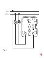
SISTEMA DE CONEXION
La conexión eléctrica de estos artículos se efectuará
conforme a la presentación de las guras siguientes.
El borne «L» marca la conexión del hilo de fase de la
instalación y la echa de salida del aparato marca la
conexión al receptor de acuerdo a lo visto en la gura
2.
NOTA: Téngase especial atención en la conexión
de los conductores entrada/salida al aparato se-
gún guras.
Asegúrese de desconectar la tensión de la insta-
lación cuando manipule el aparato.

7
FASE
NEUTRO
Fig. 2

8
En aquellas aplicaciones en las que se requiera la
temporización de un motor de menos de 40VA de po-
tencia, como por ejemplo, un pequeño motor extractor
de aire de 13VA en un baño, se podrá conectar a este
aparato teniendo en cuenta, que además habremos
de conectar otra carga al mismo, cuya potencia, su-
mada a la del motor, supere los 40VA de carga mínima
especicada para el correcto funcionamiento.
Si se conecta un motor en combinación con otra car-
ga (lámpara halógena o incandescente), la potencia
máxima permitida de esta última, se verá reducida en
un falor igual al de la potencia del motor.
Ejemplo de aplicación en gura 3

9
FASE
NEUTRO
Fig. 3

10
MONTAJE PARA SERIES SERIES MODULARES

11
MONTAJE PARA SERIES SERIES MODULARES

12
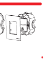
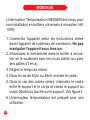
El Interruptor Temporizado NIESSEN está diseñado
para su instalación en cajas de empotrar universales
(ref. 1099).
1. Conecte el aparato según las instrucciones citadas
en el apartado de sistemas de conexión. No mani-
pular el aparato bajo tensión.
2. Introduzca el mecanismo en la caja de empotrar
sujetándolo mediante los tornillos de la caja (o me-
diante las garras, si las lleva).
3. Regule el tiempo de retardo.
4. En el caso de Stylo ó Zenit, monte el marco.
5. En el caso de las demás series, intercale el marco
entre el soporte y el cuerpo, y atornille el soporte al
cuerpo. Monte la tecla sobre el soporte.
6. El Interruptor Temporizado está preparado para su
uso.
MONTAJE

13
MONTAJE PARA SERIES DE LUJO
CUERPO
MARCO
SOPORTE TECLA
TORNILLO
Fig. 4

14
Tensión de red: 230 V
˜
/ 50 Hz.
Potencia máxima:
40-500 W para lámparas incandescentes.
40-400 VA para halógenas con transforma-
dor convencional.
40-100VA para motores.
Protección contra sobreintensidades:
Mediante fusible calibrado F-3,15H.
Se suministra con uno de recambio.
DATOS TECNICOS

15
Protección contra conexiones erróneas:
Mediante dispositivo electrónico.
Tiempo de regulación: De 10s. a 10min. (±10%).
Visor de orientación nocturna: Mediante LED de color
rojo.
Temperatura de funcionamiento: 0 a 40 ºC.
Fabricado de acuerdo a las normas:
UNE-EN 60669-1
UNE-EN 60669-2-1
UNE-EN 60669-2-3

16
MODO DE EMPLEO
Una vez realizada la conexión de los conductores
eléctricos, ajústese el valor deseado del retraso a la
desconexión median te la actuación sobre el tornillo
de ajuste.
Tras colocar la tecla, el aparato queda preparado así
para su correcto funcionamiento.
Al actuar manualmente sobre la tecla, se conectará el
elemento controlado por el Interruptor Temporizado.
La desconexión del mismo se producirá automática-
mente una vez haya transcurrido el tiempo previa-
mente ajustado.
Si se actúa sobre la tecla, o sobre cualquiera de los
pulsadores auxiliares en caso de que existan, cuan-
do todavía no ha transcurrido la totalidad del tiempo
ajustado, el aparato vuelve a iniciar la secuencia de
tiempo.

17
GARANTIA
Todos los aparatos fabricados o distribuidos por Asea
Brown Boveri, S.A. Fábrica NIESSEN están realiza-
dos de acuerdo a la más moderna tecnología.
La Fábrica NIESSEN, garantiza sus artículos, dentro
de las condiciones generales de suministro, siempre
que se trate de un defecto de fabricación. En este
caso, le rogamos remita el aparato defectuoso al dis-
tribuidor donde lo adquirió, acompañado del presente
certicado de garantía.

18
La duración de esta garantía es de 24 meses a partir
de la fecha de adquisición del aparato.
Importente: Asegúrese de que el presente certica-
do de garantía está debidamente cumplimentado por
el distribuidor.
VIGENCIA
COBERTURA
La presente garantía se aplicara a aquellos artícu-
los que presenten un defecto de fabricación. No se
aplica rá por lo tanto a los artículos que presenten
daños como consecuencia de no haber seguido co-
rrectamente las instrucciones de montaje, o cuando
las instalación haya sido realizada por personal no
especializado.
Así mismo, quedan excluidos los daños ocasionados
por uso indebido del aparato y averías producidas en
el transporte.

19
Fecha de adquisición: / /
Sello y forma del distribuidor

Cod. 7981622 - V
Asea Brown Boveri, S.A.
Fábrica NIESSEN
Polígono Industrial Aranguren, n.º 6
20180 OIARTZUN - España
Telf. 943 260 101
Fax 943 260 250
www.abb.es/niessen

TIMER SWITCH
Ref. – – – 62.1
Instructions for installation and operation.

2
Congratulations for buying this electronic
NIESSEN article.
You have just acquired the Timer Switch
with the easiest installation and great exibility
of use,
which allows for the on-off switch of the recep-
tors connected to it
to be controlled by a timer,
and offers you the benets of savings, security,
comfort and well-being
the advanced NIESSEN technology brings to
our society.
Thank you for choosing NIESSEN.

3
Lea atentamente las siguientes instrucciones antes
de utilizar el producto.
INDICE PAG.
OPERATION .......................................................................... 4
CONNECTION SYSTEM ....................................................... 6
MOUNTING ........................................................................... 10
TECHNICAL DATA ................................................................ 14
INSTRUCTIONS FOR USE .................................................. 16
WARRANTY .......................................................................... 17

4
OPERATION
The Timer Switch is an electronic operation mecha-
nism making the automatic disconnection of the con-
trolled element, within an adjustable time interval.
The manual operation is carried out by pressing the
key.
The remote control operation is made by means of
conventional auxiliary push-buttons.
Setting the desired time margin for disconnecting the
device, is carried out by using an adjusting screw, as
indicated on Figure 1. The time range is adjustable
from 10 seconds to 10 minutes (±10%).

5
Ajuste de temporización
Fig. 1

6
CONNEXION SYSTEM
The electric connection of these articles is carried out
in conformity with the presentation of the following
Figures.
The «L» terminal indicates the connection with the in-
stallation phase wire,
and the arrow exiting the device indicates the connec-
tion to the receptor,
accordingly to what can be read in Fig. 2.
NOTE: Pay particular attention to the connection
of exit/entry device conductors, as shown in the
diagrams.
When manipulating the device, make sure it is dis-
connected from the power grid.

7
FASE
NEUTRO
Fig. 2

8
For the applications requiring the timing of an engine
of less than 40VA power, for example a small air-ex-
tractor engine with 13VA in a bathroom, the connec-
tion will be possible if you connect another load to the
latter, so as to make sure the addition of both power
loads results in a power output which is greater than
40VA, the minimum load required for the correct op-
eration of the device.
If an engine is connected to another load (a halogen or
incandescent lamp), the maximum power load of the
latter has to equal the maximum power output value
of the engine.

9
FASE
NEUTRO
Fig. 3

10
MONTAJE PARA SERIES SERIES MODULARES

11
MONTAJE PARA SERIES SERIES MODULARES

12
The Timer Switch NIESSEN is designed for its instal-
lation in universal ush-mounting boxes (ref. 1099).
1. Connect the device according to the instructions
cited in the subsection on connection systems. Do
not manipulate the device when connected to the
power grid.
2. Introduce the mechanism in the ush-mounting box
holding it with the screws of the box (or with xa-
tion claws, if the box is equipped with them).
3. Set the time delay.
4. In case of Stylo or Zenit, mount the frame.
5. When mounting the other series, insert the frame
between the support and the body and screw the
support to the body. Mount the key on the support.
See Figure 4.
6. The Timer Switch is ready to use.
MOUNTING

13
MONTAJE PARA SERIES DE LUJO
BODY
FRAME
SUPPORT KEY
SCREWS
Fig. 4

14
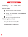
Rated Voltage: 230 V ˜ ± 10% - 50 Hz.
Maximum Output:
40-500 W for incandescent lamps.
40-400 VA for halogens with conventional
transformers.
40-100 VA motored transformer.
Protection against overloads:
Through calibrated fuse F-3, 15H
It is supplied with a replacement.
TECHNICAL DATA

15
Protection against faulty connections:
Through electronic device.
Control time: from 10 sec. to 10 min. (±10%).
Night vision device: Through red LED.
Operating temperature: from 0 to 40 ºC.
Interference suppression following the rules:
UNE-EN- 60669-1
UNE-EN- 60669-2-1
UNE-EN- 60699-2-3

16
INSTRUCTIONS FOR USE
When the connection of the electrical conductors has
been made, you may set the desired value of time de-
lay to the disconnection by operating with the setting
screw. When you rotate it in clockwise direction, the
disconnection time delay is prolonged, in such a way
that the led blinks each time it jumps to the next delay
level.
After placing the key, the device is ready to be ef-
ciently used.
When operating manually on the key, the controlled
element will connect to the Timer Switch. The discon-
nection of the latter will be automatically produced
when the previously set time delay is over.
If the key, or any of the auxiliary push-buttons, if any,
is operated before the totality of the set time delay has
come to an end, the device re-initialises the time se-
quence

17
WARRANTY
All the devices manufactured or distributed by Asea
Brown
Boveri, S.A. NIESSEN Factory, are made according to
the most modern technology.
NIESSEN factory offers a warranty on its articles with
respect to the general supply conditions and as far as
a manufacturing defect is concerned. In this case, we
request that you forward the defective device to your
supplier, with the current warranty certicate.

18
This warranty is valid for 24 months from the date of
the acquisition of the device.
Important: Ensure that the current warranty certi-
cate is properly lled by the supplier.
VALIDITY
COVER
The current warranty applies only to those articles
having a manufacturing defect. It does not apply to the
articles damaged as a consequence of a wrong read-
ing of the instructions of installation, or if the installa-
tion has been made by a non-specialized individual.
Likewise excluded are the damages caused by the
inappropriate use of the device and the defaults pro-
duced during transportation.

19
Acquisition date: / /
Supplier’s stamp and signature:

Cod. 7981622 - V
Asea Brown Boveri, S.A.
Fábrica NIESSEN
Polígono Industrial Aranguren, n.º 6
20180 OIARTZUN - España
Telf. 943 260 101
Fax 943 260 250
www.abb.es/niessen

INTERRUPTEUR
TEMPORISATEUR
Réf .- 62.1
Instructions d’installation et fonctionnement

2
Toutes nos félicitations pour l’achat de cet arti-
cle électronique NIESSEN.
Vous venez d’acquérir la Minuterie la plus facile
à installer et d’une grande exibilité d’utilisation,
qui permet la mise en marche des récepteurs
connectés par minuterie et vous offrir le béné-
ce de l’économie, de la sécurité, du confort, du
bien-être que la technologie avancée de NIES-
SEN apporte à notre société.
Merci d’avoir choisi NIESSEN.

3
Lire attentivement les instructions suivantes avant
d’utiliser le produit.
TABLE DES MATIÈRES PAG.
FONCTIONNEMENT ............................................................ 4
SYSTÈME DE CONNEXION ................................................ 6
MONTAGE ............................................................................. 10
DONNÉES TECHNIQUES .................................................... 14
MODE D’EMPLOI .................................................................. 16
GARANTIE ............................................................................ 17

4
Fonctionnement
L’interrupteur Temporisateur est un mécanisme d’ac-
tionnement électronique qui effectue la déconnexion
automatique de l’élément contrôlé dans un intervalle
de temps réglable.
L’actionnement se réalise directement de la touche.
Le réglage de la marge de temps voulue pour la dé-
connexion de l’appareil se réalise avec un tournevis
comme il est indiqué sur la gure 1. La marge de
temps réglable oscille entre 10 secondes et 10 mi-
nutes (10%)

5
Vis de réglage de temporisation
Fig. 1

6
SyStème de connexion
La connexion électrique de ces articles s’effectuera
conformément à la présentation des gures suivantes.
La borne « L» marque la connexion du l de base de
l’installation et la èche de sortie de l’appareil marque
la connexion au récepteur comme il est indiqué sur
la gure 2.
NOTE: Faites spécialement attention à la
connexion des conducteurs entrée/sortie à l’ap-
pareil selon la gure.
Assurez-vous de déconnecter la tension de l’ins-
tallation quand vous manipulez l’appareil.

7
PHASE
NEUTRE
Fig. 2

8
Dans ces applications où la temporisation d’un mo-
teur de moins de 40VA de puissance est nécessaire,
comme par exemple, un petit moteur extracteur d’air
de 13VA dans un bain, vous pourrez connecter cet
appareil en prenant en compte, qu’il faudra aussi
connecter une autre charge, dont la puissance en
plus de celle du moteur, dépasse les 40VA de charge
minimum spéciée pour un fonctionnement correct.
Si vous connectez un moteur en combinaison avec
une autre charge (lampe halogène ou incandescente),
la puissance maximum permise de cette dernière se
verra réduite sur la même valeur que la puissance du
moteur.
Exemple d’application sur la gure 3.

9
PHASE
NEUTRE
Fig. 3

10
montage pour SérieS modulaireS

11
montage pour SérieS modulaireS

12
L’interrupteur Temporisateur NIESSEN est conçu pour
son installation en boîtiers universels à encastrer (réf.
1099)
1. Connectez l’appareil selon les instructions citées
dans l’appareil de systèmes de connexion. Ne pas
manipuler l’appareil sous tension.
2. Introduisez le mécanisme dans le boîtier à encas-
trer en le soutenant avec les vis du boîtier (ou avec
des pattes s’il en a).
3. Réglez le temps de retard
4. Dans le cas de Stylo ou Zénit, montez le cadre.
5. Dans le cas des autres séries, intercalez le cadre
entre le support et le corps et vissez le support au
corps. Montez la touche sur le support. Voir gure 4.
6. L’interrupteur temporisateur est préparé pour son
utilisation.
montage

13
MONTAGE POUR SÉRIES DE LUXE
CORPS
CADRE
SUPPORT TOUCHE
VIS
Fig. 4

14
Tension d’alimentation: 230 V ˜ ± 10% - 50 Hz.
Puissance maximale:
40-500W pour lampes incandescentes.
40-400VA pour halogènes avec transforma-
teur conventionnel.
40-100VA pour moteurs.
Protection contre surintensités :
Avec fusible calibré F-3,15H
Fourni avec une pièce de rechange.
donnéeS techniqueS

15
Protection contre connexions erronées :
Avec dispositif électronique
Temps de régulation : De 10 s-.a 10 min (10%)
Viseur d’orientation nocturne : Avec LED de couleur
rouge
Température de fonctionnement : 0 à 40ºC
Fabriqué selon les normes :
UNE-EN 60669-1
UNE-EN 60669-2-1
UNE-EN 60669-2-3

16
mode d’emploi
Après la connexion des conducteurs électriques, ré-
glez la valeur voulue du retard à la déconnexion grâce
à l’actionnement sur le tournevis de réglage.
Après avoir placé la touche, l’appareil est préparé
ainsi pour fonctionner correctement.
En appuyant sur la touche, se connectera l’élément
contrôlé par l’interrupteur Temporisé. La déconnexion
se produira automatiquement après le temps prévu.
Si vous appuyez sur la touche, quand le temps total
n’est pas encore passé, l’appareil recommence la sé-
quence de temps.

17
garantie
Tous les appareils fabriqués ou distribués par Asea
Brown Boveri, S.A. Usine NIESSEN sont réalisés
grâce à la technologie la plus moderne.
L’usine NIESSEN garantit ses articles, en fonction
des conditions générales de fourniture, à condition
qu’il s’agisse d’un défaut de fabrication. Dans ce cas,
prière de remettre l’appareil défectueux au distribu-
teur auprès duquel vous vous l’êtes procuré, accom-
pagné de ce certicat de garantie.

18
La durée de cette garantie est de 24 mois à partir de la
date d’achat de l’appareil.
Important: Assurez-vous que ce certicat de garantie
est dûment rempli par le distributeur.
Vigueur
couVerture
La présente garantie s’applique aux articles qui pré-
sentent un défaut de fabrication. Elle ne s’applique
donc pas aux articles présentant des dommages dus
à une mauvaise exécution des instructions de mon-
tage, ou lorsque l’installation a été réalisée par un per-
sonnel non spécialisée.
Sont donc exclus les dommages provoqués par une
utilisation irrégulière de l’appareil et les pannes qui se
seraient produites pendant le transport.

19
Date d’achat: / /
Cachet et signature du distributeur:

Cod. 7981622 - V
Asea Brown Boveri, S.A.
Fábrica NIESSEN
Polígono Industrial Aranguren, n.º 6
20180 OIARTZUN - España
Telf. 943 260 101
Fax 943 260 250
www.abb.es/niessen
Transcripción de documentos
INTERRUPTOR TEMPORIZADO Ref. – – – 62.1 Instrucciones de instalación y funcionamiento Le felicitamos por la compra de este artículo electrónico NIESSEN. Acaba de adquirir el Interruptor Temporizado de más fácil instalación y gran flexibilidad de uso, que permite el encendido de los receptores conectados a él de manera temporizada y ofrecerle el beneficio del ahorro, seguridad, confort y bienestar que la avanzada tecnología NIESSEN aporta a nuestra sociedad. Gracias por elegir NIESSEN. 2 Lea atentamente las siguientes instrucciones antes de utilizar el producto. INDICE PAG. FUNCIONAMIENTO............................................................... 4 SISTEMA DE CONEXIÓN..................................................... 6 MONTAJE............................................................................... 10 DATOS TÉCNICOS................................................................ 14 MODO DE EMPLEO............................................................... 16 GARANTÍA............................................................................. 17 3 FUNCIONAMIENTO El Interruptor Temporizado es un mecanismo de accionamiento electrónico que efectúa la desconexión automática del elemento controlado, en un intervalo de tiempo ajustable. El accionamiento manual se realiza actuando directamente sobre la tecla. El accionamiento por control remoto se realiza mediante pulsadores convencionales auxiliares. La regulación del margen de tiempo deseado para la desconexión del aparato se realiza mediante el tornillo de ajuste, indicado en la figura 1. El margen de tiempo ajustable oscila entre 10 segundos y 10 minutos (±10%). 4 Ajuste de temporización Fig. 1 5 SISTEMA DE CONEXION La conexión eléctrica de estos artículos se efectuará conforme a la presentación de las figuras siguientes. El borne «L» marca la conexión del hilo de fase de la instalación y la flecha de salida del aparato marca la conexión al receptor de acuerdo a lo visto en la figura 2. NOTA: Téngase especial atención en la conexión de los conductores entrada/salida al aparato según figuras. Asegúrese de desconectar la tensión de la instalación cuando manipule el aparato. 6 FASE NEUTRO Fig. 2 7 En aquellas aplicaciones en las que se requiera la temporización de un motor de menos de 40VA de potencia, como por ejemplo, un pequeño motor extractor de aire de 13VA en un baño, se podrá conectar a este aparato teniendo en cuenta, que además habremos de conectar otra carga al mismo, cuya potencia, sumada a la del motor, supere los 40VA de carga mínima especificada para el correcto funcionamiento. Si se conecta un motor en combinación con otra carga (lámpara halógena o incandescente), la potencia máxima permitida de esta última, se verá reducida en un falor igual al de la potencia del motor. Ejemplo de aplicación en figura 3 8 FASE NEUTRO Fig. 3 9 MONTAJE PARA SERIES SERIES MODULARES 10 11 MONTAJE El Interruptor Temporizado NIESSEN está diseñado para su instalación en cajas de empotrar universales (ref. 1099). 1. Conecte el aparato según las instrucciones citadas en el apartado de sistemas de conexión. No manipular el aparato bajo tensión. 2. Introduzca el mecanismo en la caja de empotrar sujetándolo mediante los tornillos de la caja (o mediante las garras, si las lleva). 3. Regule el tiempo de retardo. 4. En el caso de Stylo ó Zenit, monte el marco. 5. En el caso de las demás series, intercale el marco entre el soporte y el cuerpo, y atornille el soporte al cuerpo. Monte la tecla sobre el soporte. 6. El Interruptor Temporizado está preparado para su uso. 12 MONTAJE PARA SERIES DE LUJO MARCO CUERPO Fig. 4 TORNILLO SOPORTE TECLA 13 DATOS TECNICOS Tensión de red: 230 V ˜ / 50 Hz. Potencia máxima: 40-500 W para lámparas incandescentes. 40-400 VA para halógenas con transformador convencional. 40-100VA para motores. Protección contra sobreintensidades: Mediante fusible calibrado F-3,15H. Se suministra con uno de recambio. 14 Protección contra conexiones erróneas: Mediante dispositivo electrónico. Tiempo de regulación: De 10s. a 10min. (±10%). Visor de orientación nocturna: Mediante LED de color rojo. Temperatura de funcionamiento: 0 a 40 ºC. Fabricado de acuerdo a las normas: UNE-EN 60669-1 UNE-EN 60669-2-1 UNE-EN 60669-2-3 15 MODO DE EMPLEO Una vez realizada la conexión de los conductores eléctricos, ajústese el valor deseado del retraso a la desconexión mediante la actuación sobre el tornillo de ajuste. Tras colocar la tecla, el aparato queda preparado así para su correcto funcionamiento. Al actuar manualmente sobre la tecla, se conectará el elemento controlado por el Interruptor Temporizado. La desconexión del mismo se producirá automáticamente una vez haya transcurrido el tiempo previamente ajustado. Si se actúa sobre la tecla, o sobre cualquiera de los pulsadores auxiliares en caso de que existan, cuando todavía no ha transcurrido la totalidad del tiempo ajustado, el aparato vuelve a iniciar la secuencia de tiempo. 16 GARANTIA Todos los aparatos fabricados o distribuidos por Asea Brown Boveri, S.A. Fábrica NIESSEN están realizados de acuerdo a la más moderna tecnología. La Fábrica NIESSEN, garantiza sus artículos, dentro de las condiciones generales de suministro, siempre que se trate de un defecto de fabricación. En este caso, le rogamos remita el aparato defectuoso al distribuidor donde lo adquirió, acompañado del presente certificado de garantía. 17 COBERTURA La presente garantía se aplicara a aquellos artículos que presenten un defecto de fabricación. No se aplicará por lo tanto a los artículos que presenten daños como consecuencia de no haber seguido correctamente las instrucciones de montaje, o cuando las instalación haya sido realizada por personal no especializado. Así mismo, quedan excluidos los daños ocasionados por uso indebido del aparato y averías producidas en el transporte. VIGENCIA La duración de esta garantía es de 24 meses a partir de la fecha de adquisición del aparato. Importente: Asegúrese de que el presente certificado de garantía está debidamente cumplimentado por el distribuidor. 18 Fecha de adquisición: / / Sello y forma del distribuidor 19 Cod. 7981622 - V Asea Brown Boveri, S.A. Fábrica NIESSEN Polígono Industrial Aranguren, n.º 6 20180 OIARTZUN - España Telf. 943 260 101 Fax 943 260 250 www.abb.es/niessen TIMER SWITCH Ref. – – – 62.1 Instructions for installation and operation. Congratulations for buying this electronic NIESSEN article. You have just acquired the Timer Switch with the easiest installation and great flexibility of use, which allows for the on-off switch of the receptors connected to it to be controlled by a timer, and offers you the benefits of savings, security, comfort and well-being the advanced NIESSEN technology brings to our society. Thank you for choosing NIESSEN. 2 Lea atentamente las siguientes instrucciones antes de utilizar el producto. INDICE PAG. OPERATION........................................................................... 4 CONNECTION SYSTEM........................................................ 6 MOUNTING............................................................................ 10 TECHNICAL DATA................................................................. 14 INSTRUCTIONS FOR USE................................................... 16 WARRANTY........................................................................... 17 3 OPERATION The Timer Switch is an electronic operation mechanism making the automatic disconnection of the controlled element, within an adjustable time interval. The manual operation is carried out by pressing the key. The remote control operation is made by means of conventional auxiliary push-buttons. Setting the desired time margin for disconnecting the device, is carried out by using an adjusting screw, as indicated on Figure 1. The time range is adjustable from 10 seconds to 10 minutes (±10%). 4 Ajuste de temporización Fig. 1 5 CONNEXION SYSTEM The electric connection of these articles is carried out in conformity with the presentation of the following Figures. The «L» terminal indicates the connection with the installation phase wire, and the arrow exiting the device indicates the connection to the receptor, accordingly to what can be read in Fig. 2. NOTE: Pay particular attention to the connection of exit/entry device conductors, as shown in the diagrams. When manipulating the device, make sure it is disconnected from the power grid. 6 FASE NEUTRO Fig. 2 7 For the applications requiring the timing of an engine of less than 40VA power, for example a small air-extractor engine with 13VA in a bathroom, the connection will be possible if you connect another load to the latter, so as to make sure the addition of both power loads results in a power output which is greater than 40VA, the minimum load required for the correct operation of the device. If an engine is connected to another load (a halogen or incandescent lamp), the maximum power load of the latter has to equal the maximum power output value of the engine. 8 FASE NEUTRO Fig. 3 9 MONTAJE PARA SERIES SERIES MODULARES 10 11 MOUNTING The Timer Switch NIESSEN is designed for its installation in universal flush-mounting boxes (ref. 1099). 1. Connect the device according to the instructions cited in the subsection on connection systems. Do not manipulate the device when connected to the power grid. 2. Introduce the mechanism in the flush-mounting box holding it with the screws of the box (or with fixation claws, if the box is equipped with them). 3. Set the time delay. 4. In case of Stylo or Zenit, mount the frame. 5. When mounting the other series, insert the frame between the support and the body and screw the support to the body. Mount the key on the support. See Figure 4. 6. The Timer Switch is ready to use. 12 MONTAJE PARA SERIES DE LUJO FRAME BODY Fig. 4 SCREWS SUPPORT KEY 13 TECHNICAL DATA Rated Voltage: 230 V ˜ ± 10% - 50 Hz. Maximum Output: 40-500 W for incandescent lamps. 40-400 VA for halogens with conventional transformers. 40-100 VA motored transformer. Protection against overloads: Through calibrated fuse F-3, 15H It is supplied with a replacement. 14 Protection against faulty connections: Through electronic device. Control time: from 10 sec. to 10 min. (±10%). Night vision device: Through red LED. Operating temperature: from 0 to 40 ºC. Interference suppression following the rules: UNE-EN- 60669-1 UNE-EN- 60669-2-1 UNE-EN- 60699-2-3 15 INSTRUCTIONS FOR USE When the connection of the electrical conductors has been made, you may set the desired value of time delay to the disconnection by operating with the setting screw. When you rotate it in clockwise direction, the disconnection time delay is prolonged, in such a way that the led blinks each time it jumps to the next delay level. After placing the key, the device is ready to be efficiently used. When operating manually on the key, the controlled element will connect to the Timer Switch. The disconnection of the latter will be automatically produced when the previously set time delay is over. If the key, or any of the auxiliary push-buttons, if any, is operated before the totality of the set time delay has come to an end, the device re-initialises the time sequence 16 WARRANTY All the devices manufactured or distributed by Asea Brown Boveri, S.A. NIESSEN Factory, are made according to the most modern technology. NIESSEN factory offers a warranty on its articles with respect to the general supply conditions and as far as a manufacturing defect is concerned. In this case, we request that you forward the defective device to your supplier, with the current warranty certificate. 17 COVER The current warranty applies only to those articles having a manufacturing defect. It does not apply to the articles damaged as a consequence of a wrong reading of the instructions of installation, or if the installation has been made by a non-specialized individual. Likewise excluded are the damages caused by the inappropriate use of the device and the defaults produced during transportation. VALIDITY This warranty is valid for 24 months from the date of the acquisition of the device. Important: Ensure that the current warranty certificate is properly filled by the supplier. 18 Acquisition date: / / Supplier’s stamp and signature: 19 Cod. 7981622 - V Asea Brown Boveri, S.A. Fábrica NIESSEN Polígono Industrial Aranguren, n.º 6 20180 OIARTZUN - España Telf. 943 260 101 Fax 943 260 250 www.abb.es/niessen INTERRUPTEUR TEMPORISATEUR Réf .- 62.1 Instructions d’installation et fonctionnement Toutes nos félicitations pour l’achat de cet article électronique NIESSEN. Vous venez d’acquérir la Minuterie la plus facile à installer et d’une grande flexibilité d’utilisation, qui permet la mise en marche des récepteurs connectés par minuterie et vous offrir le bénéfice de l’économie, de la sécurité, du confort, du bien-être que la technologie avancée de NIESSEN apporte à notre société. Merci d’avoir choisi NIESSEN. 2 Lire attentivement les instructions suivantes avant d’utiliser le produit. TABLE DES MATIÈRES PAG. FONCTIONNEMENT............................................................. 4 SYSTÈME DE CONNEXION................................................. 6 MONTAGE.............................................................................. 10 DONNÉES TECHNIQUES..................................................... 14 MODE D’EMPLOI................................................................... 16 GARANTIE............................................................................. 17 3 Fonctionnement L’interrupteur Temporisateur est un mécanisme d’actionnement électronique qui effectue la déconnexion automatique de l’élément contrôlé dans un intervalle de temps réglable. L’actionnement se réalise directement de la touche. Le réglage de la marge de temps voulue pour la déconnexion de l’appareil se réalise avec un tournevis comme il est indiqué sur la figure 1. La marge de temps réglable oscille entre 10 secondes et 10 minutes (10%) 4 Vis de réglage de temporisation Fig. 1 5 Système de connexion La connexion électrique de ces articles s’effectuera conformément à la présentation des figures suivantes. La borne « L» marque la connexion du fil de base de l’installation et la flèche de sortie de l’appareil marque la connexion au récepteur comme il est indiqué sur la figure 2. NOTE: Faites spécialement attention à la connexion des conducteurs entrée/sortie à l’appareil selon la figure. Assurez-vous de déconnecter la tension de l’installation quand vous manipulez l’appareil. 6 PHASE NEUTRE Fig. 2 7 Dans ces applications où la temporisation d’un moteur de moins de 40VA de puissance est nécessaire, comme par exemple, un petit moteur extracteur d’air de 13VA dans un bain, vous pourrez connecter cet appareil en prenant en compte, qu’il faudra aussi connecter une autre charge, dont la puissance en plus de celle du moteur, dépasse les 40VA de charge minimum spécifiée pour un fonctionnement correct. Si vous connectez un moteur en combinaison avec une autre charge (lampe halogène ou incandescente), la puissance maximum permise de cette dernière se verra réduite sur la même valeur que la puissance du moteur. Exemple d’application sur la figure 3. 8 PHASE NEUTRE Fig. 3 9 Montage pour séries modulaires 10 11 Montage L’interrupteur Temporisateur NIESSEN est conçu pour son installation en boîtiers universels à encastrer (réf. 1099) 1. Connectez l’appareil selon les instructions citées dans l’appareil de systèmes de connexion. Ne pas manipuler l’appareil sous tension. 2. Introduisez le mécanisme dans le boîtier à encastrer en le soutenant avec les vis du boîtier (ou avec des pattes s’il en a). 3. Réglez le temps de retard 4. Dans le cas de Stylo ou Zénit, montez le cadre. 5. Dans le cas des autres séries, intercalez le cadre entre le support et le corps et vissez le support au corps. Montez la touche sur le support. Voir figure 4. 6. L’interrupteur temporisateur est préparé pour son utilisation. 12 MONTAGE POUR SÉRIES DE LUXE CADRE CORPS Fig. 4 VIS SUPPORT TOUCHE 13 Données techniques Tension d’alimentation: 230 V ˜ ± 10% - 50 Hz. Puissance maximale: 40-500W pour lampes incandescentes. 40-400VA pour halogènes avec transformateur conventionnel. 40-100VA pour moteurs. Protection contre surintensités : Avec fusible calibré F-3,15H Fourni avec une pièce de rechange. 14 Protection contre connexions erronées : Avec dispositif électronique Temps de régulation : De 10 s-.a 10 min (10%) Viseur d’orientation nocturne : Avec LED de couleur rouge Température de fonctionnement : 0 à 40ºC Fabriqué selon les normes : UNE-EN 60669-1 UNE-EN 60669-2-1 UNE-EN 60669-2-3 15 MODe D’EMPLOi Après la connexion des conducteurs électriques, réglez la valeur voulue du retard à la déconnexion grâce à l’actionnement sur le tournevis de réglage. Après avoir placé la touche, l’appareil est préparé ainsi pour fonctionner correctement. En appuyant sur la touche, se connectera l’élément contrôlé par l’interrupteur Temporisé. La déconnexion se produira automatiquement après le temps prévu. Si vous appuyez sur la touche, quand le temps total n’est pas encore passé, l’appareil recommence la séquence de temps. 16 GARANTIE Tous les appareils fabriqués ou distribués par Asea Brown Boveri, S.A. Usine NIESSEN sont réalisés grâce à la technologie la plus moderne. L’usine NIESSEN garantit ses articles, en fonction des conditions générales de fourniture, à condition qu’il s’agisse d’un défaut de fabrication. Dans ce cas, prière de remettre l’appareil défectueux au distributeur auprès duquel vous vous l’êtes procuré, accompagné de ce certificat de garantie. 17 Couverture La présente garantie s’applique aux articles qui présentent un défaut de fabrication. Elle ne s’applique donc pas aux articles présentant des dommages dus à une mauvaise exécution des instructions de montage, ou lorsque l’installation a été réalisée par un personnel non spécialisée. Sont donc exclus les dommages provoqués par une utilisation irrégulière de l’appareil et les pannes qui se seraient produites pendant le transport. VIGueur La durée de cette garantie est de 24 mois à partir de la date d’achat de l’appareil. Important: Assurez-vous que ce certificat de garantie est dûment rempli par le distributeur. 18 Date d’achat: / / Cachet et signature du distributeur: 19 Cod. 7981622 - V Asea Brown Boveri, S.A. Fábrica NIESSEN Polígono Industrial Aranguren, n.º 6 20180 OIARTZUN - España Telf. 943 260 101 Fax 943 260 250 www.abb.es/niessen-
 1
1
-
 2
2
-
 3
3
-
 4
4
-
 5
5
-
 6
6
-
 7
7
-
 8
8
-
 9
9
-
 10
10
-
 11
11
-
 12
12
-
 13
13
-
 14
14
-
 15
15
-
 16
16
-
 17
17
-
 18
18
-
 19
19
-
 20
20
-
 21
21
-
 22
22
-
 23
23
-
 24
24
-
 25
25
-
 26
26
-
 27
27
-
 28
28
-
 29
29
-
 30
30
-
 31
31
-
 32
32
-
 33
33
-
 34
34
-
 35
35
-
 36
36
-
 37
37
-
 38
38
-
 39
39
-
 40
40
-
 41
41
-
 42
42
-
 43
43
-
 44
44
-
 45
45
-
 46
46
-
 47
47
-
 48
48
-
 49
49
-
 50
50
-
 51
51
-
 52
52
-
 53
53
-
 54
54
-
 55
55
-
 56
56
-
 57
57
-
 58
58
-
 59
59
-
 60
60


ABB NIESSEN 62.1 Instructions For Installation And Operation Manual
- Tipo
- Instructions For Installation And Operation Manual
En otros idiomas
- français: ABB NIESSEN 62.1
- English: ABB NIESSEN 62.1