Dell PowerConnect 5424 Guía de inicio rápido
- Tipo
- Guía de inicio rápido

www.dell.com | support.dell.com
Dell™ PowerConnect™ 54xx
Systems
Getting Started Guide
Փ⫼ܹ䮼ᣛफ
Začínáme
Guide de mise en route
Handbuch zum Einstieg
Οδηγός για γρήγορο ξεκίνημα
͉̲͛ͅ
시작 설명서
Instrukcja uruchomienia
Guía de introducción
Ba


www.dell.com | support.dell.com
Dell™ PowerConnect™ 54xx
Systems
Getting Started Guide

Notes, Notices, and Cautions
NOTE: A NOTE indicates important information that helps to make better use of the device.
NOTICE: A NOTICE indicates either potential damage to hardware or loss of data and gives information
how to avoid the problem.
CAUTION: A CAUTION indicates a potential for property damage, personal injury, or death.
____________________
+PHQTOCVKQPKPVJKUFQEWOGPVKUUWDLGEVVQEJCPIGYKVJQWVPQVKEG
l &GNN +PE #NN TKIJVU TGUGTXGF
4GRTQFWEVKQPKPCP[OCPPGTYJCVUQGXGTYKVJQWVVJGYTKVVGPRGTOKUUKQPQH&GNN+PEKUUVTKEVN[HQTDKFFGP
6TCFGOCTMUWUGFKPVJKUVGZV&GNN&GNN1RGP/CPCIGVJG&'..NQIQ+PURKTQP&GNN2TGEKUKQP&KOGPUKQP1RVK2NGZ2QYGT%QPPGEV
2QYGT#RR2QYGT8CWNV#ZKO&GNN0GVCPF.CVKVWFGCTGVTCFGOCTMUQH&GNN+PE/KETQUQHV9KPFQYU9KPFQYU5GTXGT
CPF9KPFQYU8KUVCCTGGKVJGTVTCFGOCTMUQTTGIKUVGTGFVTCFGOCTMUQH/KETQUQHV%QTRQTCVKQPKPVJG7PKVGF5VCVGUCPFQTQVJGTEQWPVTKGU
1VJGTVTCFGOCTMUCPFVTCFGPCOGUOC[DGWUGFKPVJKUFQEWOGPVVQTGHGTVQGKVJGTVJGGPVKVKGUENCKOKPIVJGOCTMUCPFPCOGU
QTVJGKTRTQFWEVU&GNN+PEFKUENCKOUCP[RTQRTKGVCT[KPVGTGUVKPVTCFGOCTMUCPFVTCFGPCOGUQVJGTVJCPKVUQYP
November 2007 P/N NG720
Rev. A01

Contents 3
Contents
1 Installation
Overview . . . . . . . . . . . . . . . . . . . . . . . . . . . . . . . . . . . . . . . . . . . . . . . . . . . . . . . . . . . . . . . 5
Site Preparation . . . . . . . . . . . . . . . . . . . . . . . . . . . . . . . . . . . . . . . . . . . . . . . . . . . . . . . . . 5
Site Requirements . . . . . . . . . . . . . . . . . . . . . . . . . . . . . . . . . . . . . . . . . . . . . . . . . . . 5
Unpacking . . . . . . . . . . . . . . . . . . . . . . . . . . . . . . . . . . . . . . . . . . . . . . . . . . . . . . . . . . . . . . 6
Package Contents. . . . . . . . . . . . . . . . . . . . . . . . . . . . . . . . . . . . . . . . . . . . . . . . . . . . 6
Unpacking the Device . . . . . . . . . . . . . . . . . . . . . . . . . . . . . . . . . . . . . . . . . . . . . . . . 6
2 Mounting the Device
Overview . . . . . . . . . . . . . . . . . . . . . . . . . . . . . . . . . . . . . . . . . . . . . . . . . . . . . . . . . . . . . . . 7
Device Rack Installation . . . . . . . . . . . . . . . . . . . . . . . . . . . . . . . . . . . . . . . . . . . . . . 7
Installing on a Flat Surface . . . . . . . . . . . . . . . . . . . . . . . . . . . . . . . . . . . . . . . . . . . . 8
Installing on a Wall. . . . . . . . . . . . . . . . . . . . . . . . . . . . . . . . . . . . . . . . . . . . . . . . . . . 8
Connecting a Device to a Power Supply . . . . . . . . . . . . . . . . . . . . . . . . . . . . . . . . 9
3 Starting and Configuring the Device
Connecting the Terminal to the Device . . . . . . . . . . . . . . . . . . . . . . . . . . . . . . . . . . . . 11
Booting the Switch . . . . . . . . . . . . . . . . . . . . . . . . . . . . . . . . . . . . . . . . . . . . . . . . . . . . . 13
Initial Configuration . . . . . . . . . . . . . . . . . . . . . . . . . . . . . . . . . . . . . . . . . . . . . . . . . . . . . 13

4 Contents

Installation 5
Installation
Overview
This document provides basic information to install and start running the PowerConnect 5400 series
switches. For more information, see the Dell™ PowerConnect™ 5400 series User’s Guide, which is
available on your Documentation CD or check the Dell support website at www.support.dell.com
for latest updates on documentations and software.
Site Preparation
Site Requirements
PowerConnect 5400 series devices can be mounted in a standard 19 inch (48.26 centimeters)
equipment rack or placed on a table-top. Before installing the unit, verify that the chosen location
for installation meets the site requirements described below.
•
Power
— The unit is installed near an easily accessible outlet 100-250 VAC, 50-60 Hz. It is
preferred that two separate power supplies are provided, for example, an RPS and a separated
phased supply.
•
General
— Ensure that the power supply is correctly installed by checking the LEDs on the front
panel are lit.
•
Clearance
— There is adequate frontal clearance for operator access. Allow clearance for cabling,
power connections and ventilation.
•
Cabling
— The cabling is routed to avoid sources of electrical noise such as radio transmitters,
broadcast amplifiers, power lines and fluorescent lighting fixtures.
•
Ambient Requirements
— The ambient unit operating temperature range is 0 to 45ºC (32 to 113ºF)
at a relative humidity of 10% to 90%, non-condensing.

6 Installation
Unpacking
Package Contents
While unpacking the device, ensure that the following items are included:
• Device/Switch
• AC power cable
• RS-232 crossover cable
• Self-adhesive rubber pads
• Rack mount kit for rack installation
• Documentation CD
Unpacking the Device
NOTE: Before unpacking the device, inspect the package and immediately report any evidence of damage.
1
Place the container on a clean flat surface and cut all straps securing the container.
2
Open the container or remove the container top.
3
Carefully remove the unit from the container and place it on a secure and clean surface.
4
Remove all packing material.
5
Inspect the product for damage. Report any damage immediately.

Mounting the Device 7
Mounting the Device
Overview
The following mounting instructions apply to the PowerConnect 5400 series switches. The power
connectors for the device is positioned on the back panel. Connecting a Redundant Power Supply (RPS)
is optional, but is recommended. The RPS connector is located on the device back panel.
Device Rack Installation
CAUTION: Read the safety information in the Product information Guide as well as the safety information
for other devices that connect to or support the switch.
CAUTION: Disconnect all cables from the unit before mounting the device in a rack or cabinet.
CAUTION: When mounting multiple devices into a rack, mount the devices from the bottom up.
1
Place the supplied rack-mounting bracket on one side of the device ensuring the mounting holes
on the device line up to the mounting holes on the rack mounting bracket. The following figure
illustrates where to mount the brackets.
Figure 2-1. Bracket Installation for Rack Mounting

8 Mounting the Device
2
Insert the supplied screws into the rack mounting holes and tighten with a screwdriver.
3
Repeat the process for the rack-mounting bracket on the other side of the device.
4
Insert the unit into the 19 inch (48.26 centimeters) rack ensuring the rack-mounting holes
on the device line up to the mounting hole on the rack.
5
Secure the unit to the rack with the rack screws (not provided). Fasten the lower pair of screws
before the upper pair of screws. Ensure that the ventilation holes are not obstructed.
Installing on a Flat Surface
The device must be installed on a flat surface if it is not installed on a rack. The surface must be able
to support the weight of the device and the device cables.
1
Attach rubber feet on each marked location on the bottom of the device chassis.
2
Set the device on a flat surface, while leaving 2 inches (5.08 centimeters) on each side and 5 inches
(12.7 centimeters) at the back.
3
Ensure that the device has proper ventilation.
Installing on a Wall
To mount the switch on a wall:
1
Ensure that the mounting location meets the following requirements:
• The surface of the wall must be capable of supporting the switch.
• Allow at least 5.1 cm (2 inches) space on the sides for proper ventilation and 12.7 cm (5 inches)
at the back for power cable clearance.
• The location must not be exposed to direct sunlight.
• The location must be at least 2 feet away from any heating vents, and no area-heating vent should
point towards the unit.
• The location must be ventilated to prevent heat buildup.
• Do not locate the switch near any data or electrical cabling.
• The power cable must be able to reach an outlet.
2
Use the supplied screws to attach a mounting bracket to each side of the switch
(see the following figure).

Mounting the Device 9
Figure 2-2. Bracket Installation for Wall Mounting
Connecting a Device to a Power Supply
1
Using the supplied AC power cable, connect the power cable to the AC connector located on the back
panel.
2
Do not connect the power cable to a grounded AC outlet at this time. Connect the device to a power
source in the steps detailed in Starting and Configuring the Device.

10 Mounting the Device
Figure 2-3. Connecting to Power Supply
3
Confirm that the device is connected and operating correctly by examining the LEDs
on the front panel.
PowerConnect
Rear View
Back Panel

Starting and Configuring the Device 11
Starting and Configuring the Device
After completing all external connections, connect a terminal to the device to configure the device.
Performing the additional advanced functions is described in the Dell™ PowerConnect™ 5400 User’s
Guide located on the documentation CD.
NOTE: Before proceeding, read the release notes for this product. The release notes can be downloaded
from http://support.dell.com.
NOTE: It is recommended that you obtain the most recent revision of the user documentation
from the Dell support website at http://support.dell.com.
Connecting the Terminal to the Device
The device provides a Console port, that enables a connection to a terminal desktop system running
terminal emulation software for monitoring and configuring the device. The Console port connector
is a male DB-9 connector, implemented as a data terminal equipment (DTE) connector.
To use the Console port, the following is required:
• VT100 compatible terminal or a desktop or portable system with a serial port and running VT100
terminal emulation software.
• An RS-232 crossover cable with a female DB-9 connector for the Console port and the appropriate
connector for the terminal.
To connect a terminal to the device Console port, perform the following:
1
Connect the supplied RS-232 crossover cable to the terminal running VT100 terminal emulation
software.
2
Ensure that the terminal emulation software is set as follows:
a
Select the appropriate serial port (serial port 1 or serial port 2) to connect to the console.
b
Set the data rate to 9600 baud.
c
Set the data format to 8 data bits, 1 stop bit, and no parity.

12 Starting and Configuring the Device
d
Set flow control to none.
e
Under Properties, select VT100 for Emulation mode.
f
Select Terminal keys for Function, Arrow, and Ctrl keys. Ensure that the setting is for Terminal
keys (not Windows keys).
NOTICE: When using HyperTerminal with Microsoft
®
Windows 2000, Windows XP, or Windows Vista™, ensure
that you have the latest service packs installed. With Windows 2000 Service Pack 2, the arrow keys function
properly in HyperTerminal’s VT100 emulation. Go to www.microsoft.com for information on Windows 2000,
Windows XP, and Windows Vista service packs.
3
Connect the female connector of the RS-232 crossover cable directly to the device Console port on
the Master unit/standalone device, and tighten the captive retaining screws. The PowerConnect 5400
series Console port is located on the back panel.
Figure 3-1. Connecting to PowerConnect 5400 Series Console Port
RS-232 Crossover Cable
Back Panel

Starting and Configuring the Device 13
Booting the Switch
To boot the switch, perform the following:
1
Ensure that the device console port is connected to a VT100 terminal device or VT100 terminal
emulator via the RS-232 crossover cable.
2
Locate an AC power receptacle.
3
Deactivate the AC power receptacle.
4
Connect the device to the AC receptacle.
5
Activate the AC power receptacle.
When the power is turned on with the local terminal already connected, the switch goes through Power
On Self Test (POST). POST runs every time the device is initialized and checks hardware components to
determine if the device is fully operational before completely booting. If a critical problem is detected,
the program flow stops. If POST passes successfully, a valid executable image is loaded into RAM. POST
messages are displayed on the terminal and indicate test success or failure.
The boot process runs approximately 90 seconds.
Initial Configuration
NOTE: Before proceeding, read the release notes for this product. You can download the release notes from Dell
support website at http://support.dell.com.
NOTE: The initial simple configuration uses the following assumptions:
• The PowerConnect device was never configured before, and is in the same state as when you received it.
• The PowerConnect device booted successfully.
• The console connection is established and the console prompt is displayed on the screen of a VT100 terminal
device. (Press the <Enter> key several times to verify that the prompt displays correctly.)
The initial device configuration is through the Serial port. After the initial configuration, the device can
then be managed either from the already connected Serial port or remotely through an interface defined
during the initial configuration.
The system prompts you to use the Set-up wizard when the device boots up for the first time or if the
configuration file is empty because the device is not configured. The Setup Wizard provides guidance
through the initial device configuration, and gets the device up and running as quickly as possible.
NOTE: Obtain the following information from your network administrator before configuring the device:
• SNMP Community String and SNMP Management System IP address (optional).
• Username and Password.
• The IP address to be assigned to the VLAN 1 interface through which the device is to be managed (by default,
every external and internal port is a member of the VLAN 1)
• The IP subnet mask for the network
• The default gateway (next hop router) IP address for configuring the default route.

14 Starting and Configuring the Device
The Setup Wizard guides you through the initial switch configuration, and gets the system up and running
as quickly as possible. You can skip using the setup wizard and configure the switch manually through the
device CLI mode. Consult the
PowerConnect 5400 Series User's Guide
for assistance in configuring the
device using CLI.
The Setup Wizard configures the following fields.
• SNMP Community String and SNMP Management System IP address (optional)
• Username and Password
• Device IP address
• IP subnet mask
• Default Gateway IP address
The Setup Wizard displays the following information:
Welcome to Dell Easy Setup Wizard
The Setup Wizard guides you through the initial switch configuration,
and gets you up and running easily and quickly. You can also skip
the setup wizard, and enter CLI mode to manually configure the switch
if you prefer. You can exit the setup wizard any time by entering
{CNTRL+Z]. The system will prompt you with a default answer.
By pressing Enter, you accept the default value.
Would you like to skip the setup wizard? [Y/N] N
If you enter[Y], the Set-up wizard exits. If you do not respond within 60 seconds, the Set-up wizard
automatically exits and the CLI console prompt appears.
If you enter [N], the Set-up wizard provides interactive guidance through the initial device configuration.
NOTE: You can exit the setup wizard at any time by entering [CNTRL+Z].
NOTE: If you do not respond to any prompt within 60 seconds, the Set-up wizard automatically exits. And, none
of your changes are saved.
Wizard Step 1
The following information displays:
The system is not setup for SNMP management by default. To manage
the switch using SNMP (required for Dell Network Manager) you can:
•
Setup the initial SNMP version 2 account now.
•
Return later and setup the SNMP version account. (For more
information on setting up a SNMP version 2 account, see the user
documentation).
Would you like to setup the SNMP management interface now? [Y/N] Y
Enter [N] to skip to Step 2.

Starting and Configuring the Device 15
Enter [Y] to continue the Set-up wizard. The following information displays:
To setup the SNMP management account you must specify the management
system IP address and the "community string" or password that the
particular management system uses to access the switch. The wizard
automatically assigns the highest access level [Privilege Level 15]
to this account. You can use Dell Network Manager or other management
interfaces to change this setting later, and to add additional
management system later. For more information on adding management
systems, see the user documentation.
To add a management station:
Please enter the SNMP community string to be used:[MYSETUPWIZARD] >>
Dell Network Manager
Please enter the IP address of the Management System (A.B.C.D) or wildcard (0.0.0.0) to manage
from any Management Station, for example 192.168.1.10. Press
Enter
.
Wizard Step 2
The following information displays:
Now we need to setup your initial privilege (Level 15) user account.
This account is used to login to the CLI and Web interface. You may
setup other accounts and change privilege levels later. For more
information on setting up user accounts and changing privilege
levels, see the user documentation.
To setup a user account:
Please enter the user name:
Please enter the user password:
Please reenter the user password:
Enter the Following:
• User name, for example "admin"
• Password and password confirmation.
NOTE: The system prompts you if the first and second password entries are not identical.
Press
Enter
.

16 Starting and Configuring the Device
Wizard Step 3
The following information displays:
Next, an IP address is setup. The IP address is defined on the
default VLAN (VLAN #1), of which all ports are members. This is
the IP address you use to access the CLI, Web interface, or SNMP
interface for the switch.
To setup an IP address:
Please enter the IP address of the device (A.B.C.D):
Please enter the IP subnet mask (A.B.C.D or /nn):
Enter the IP address and IP subnet mask, for example 192.168.1.100 as the IP address and 255.255.255.0
as the IP subnet mask.
Press
Enter
.
Wizard Step 4
The following information displays:
Finally, setup the default gateway. Please enter the IP address
of the gateway from which this network is reachable
(e.g. 192.168.1.1):
Enter the default gateway.
Press
Enter
. The following is displayed (as per the example parameters described):
This is the configuration information that has been collected:
SNMP Interface = "Dell Network Manager"@192.168.1.10
User Account setup = admin
Password = **********
Management IP address = 192.168.1.100 255.255.255.0
Default Gateway = 192.168.1.1

Starting and Configuring the Device 17
Wizard Step 5
The following information displays:
If the information is correct, please select (Y) to save the
configuration, and copy to the start-up configuration file. If the
information is incorrect, select (N) to discard configuration and
restart the wizard: [Y/N]
Enter [N] to skip to restart the wizard.
Enter [Y] to complete the Set-up wizard. The following is displayed:
Thank you for using Dell Easy Setup Wizard. You will now enter CLI
mode.
Wizard Step 6
The CLI prompt displays. Consult the
PowerConnect 5400 Series User's Guide
for more information.

18 Starting and Configuring the Device

www.dell.com | support.dell.com
Dell™ PowerConnect™ 54xx ㋏㒳
Փ⫼ܹ䮼ᣛफ

ᓖĂᓖፀਜ਼வস
ᓖǖĀ⊼ā㸼⼎ৃҹᐂࡽᙼདഄՓ⫼䆒ⱘ䞡㽕ֵᙃDŽ
ᓖፀǖĀ⊼ᛣā㸼⼎ৃ㛑Ӯᤳണ⹀ӊᇐ㟈᭄϶༅ˈᑊᦤկབԩ䙓ܡℸ㉏䯂乬ⱘֵᙃDŽ
வসǖĐவসđܭာభถ્߲ሚࡴᒘݤޘႼပĂཽစᒗႌᅾࡼ༽ౚă
____________________
ᴀ䇈ᯢ᭛ӊЁⱘֵᙃབ᳝ᬍˈᘩϡ㸠䗮ⶹDŽ
© 2007 Dell Inc.
⠜ᴗ᠔᳝ˈ㗏ॄᖙおDŽ
㒣
Dell Inc.
к䴶䆌ৃˈϹ⽕ҹӏԩᔶᓣ䖯㸠ࠊDŽ
ᴀ᭛ЁՓ⫼ⱘଚᷛ˖
Dell
ǃ
Dell OpenManage
ǃ
DELL
ᖑᷛǃ
Inspiron
ǃ
Dell Precision
ǃ
Dimension
ǃ
OptiPlex
ǃ
PowerConnect
ǃ
PowerApp
ǃ
PowerVault
ǃ
Axim
ǃ
DellNet
Latitude
ᰃ
Dell Inc.
ⱘଚᷛDŽ
Microsoft
ǃ
Windows
ǃ
Windows Server
Windows Vista
ᰃ
Microsoft
Corporation
㕢
/
݊ᅗᆊ
/
ഄऎⱘଚᷛ⊼ݠଚᷛDŽ
ᴀ᭛ӊЁ䗄ঞⱘ݊ᅗଚᷛѻકৡ⿄ᰃᣛᢹ᳝Ⳍᑨଚᷛৡ⿄ⱘ݀ৌ݊ࠊ䗴ⱘѻકDŽ
Dell Inc.
ᇍᴀ݀ৌⱘଚᷛѻકৡ⿄П
ⱘ݊ᅗଚᷛѻકৡ⿄ϡᢹ᳝ӏԩϧ᳝ᴗDŽ
2007
ฤ
11
Ꮬ
P/N NG720
Rev. A01

Ⳃᔩ 21
ഺ
1 ᅝ㺙
ὖ㾜 23
⦄എޚ 23
⦄എ㽕∖ 23
ᠧᓔࣙ㺙 24
ࣙ㺙ㆅ⠽ક 24
ᠧᓔ䆒ⱘࣙ㺙 24
2 ᅝ㺙䆒
ὖ㾜 25
䆒ᴎᶊᅝ㺙 25
ᑇഺ㸼䴶Ϟᅝ㺙 26
Ϟᅝ㺙 26
ᇚ䆒Ϣ⬉⑤䖲 27
3 ਃࡼ䜡㕂䆒
ᇚ㒜ッϢ䆒Ⳍ䖲 29
ᓩᇐѸᤶᴎ 30
߱ྟ䜡㕂 31

22 Ⳃᔩ

ᅝ㺙 23
ڔᓤ
গಂ
ᴀ䇈ᯢ᭛ӊᦤկњᅝ㺙ᓔྟ䖤㸠
PowerConnect 5400
㋏߫ѸᤶᴎⱘᴀֵᙃDŽ᳝݇䆺ᚙˈ
䇋খ䯙
Dell™ PowerConnect™ 5400 series User's Guide
˄
Dell™ PowerConnect™ 5400
㋏߫⫼᠋
ᣛफ˅ˈ䖭ѯֵᙃৃҢ䇈ᯢ᭛ӊ
CD
㦋ᕫ˗ᙼгৃҹᶹ䯙
Dell
ᬃᣕ㔥キ
www.support.dell.com
ҹ㦋ᕫ᳝݇䇈ᯢ᭛ӊ䕃ӊⱘ᳔ᮄᮄDŽ
ሚޝᓰ۸
ሚޝገཇ
PowerConnect 5400
㋏߫䆒ৃҹᅝ㺙ᷛޚⱘ
19
㣅ᇌ˄
48.26
६㉇˅䆒ᴎᶊЁˈгৃҹᬒ
Ḡ䴶ϞDŽᅝ㺙䆹㺙㕂Пࠡˈ䇋偠䆕᠔䗝ⱘᅝ㺙ԡ㕂ᰃ৺ヺড়བϟ᠔䗄ⱘ⦄എ㽕∖DŽ
•
⬉⑤㽕∖
ü
㺙㕂ᑨ䴴䖥ᯧѢᦦᢨⱘ⬉⑤ᦦᑻ
(100-250 VAC, 50-60 Hz)
䖯㸠ᅝ㺙DŽ᳔དᦤկϸ
Ͼऩ⣀ⱘ⬉⑤䆒ˈ՟བϔϾ
RPS
ϔϾऩ⣀Ⳍԡ⬉⑤䆒DŽ
•
ϔ㠀㽕∖
ü
Ẕᶹࠡ䴶ᵓϞ
LED
ᣛ⼎♃ⱘ҂䍋ᚙމˈ⹂ֱ⬉⑤䆒ᅝ㺙ℷ⹂DŽ
•
ぎ䯈㽕∖
ü
ℷ䴶ᑨ᳝䎇ぎ䯈ҹ֓᪡ਬ䖯㸠᪡DŽ䇋⬭ߎ⫼ѢᏗ㒓ǃ
⬉⑤䖲䗮亢ⱘぎ䯈DŽ
• Ꮧ㒓㽕∖
ü
Ꮧ㒓ᑨ䖰⾏⬉ᄤాໄ⑤˄བ᮴㒓⬉থᇘ఼ǃᑓ᪁ᬒ఼ǃ⬉⑤㒓䏃㤻ܝ✻
ᯢ㺙㕂˅DŽ
•
⦃๗㽕∖
ü
㺙㕂䖤㸠⦃๗⏽ᑺ㣗ೈЎ
0
ࠄ
45
ºC
˄
32
ࠄ
113
ºF
˅ˈⳌᇍᑺЎ
10%
ࠄ
90%
ˈ
䴲ދޱDŽ

24 ᅝ㺙
ࡌఎ۞ᓤ
۞ᓤረᇕອ
ᠧᓔ䆒ࣙ㺙ᯊˈ䇋⹂ֱ݊Ёࣙҹϟ乍˖
•
䆒
/
Ѹᤶᴎ
•
Ѹ⌕⬉⑤㒓
•
RS-232
㒲⬉㓚
•
㞾㉬㛊ൿ
•
⫼Ѣᴎᶊᅝ㺙ⱘᴎᶊᅮ༫ӊ
•
䇈ᯢ᭛ӊ
CD
ࡌఎ۸ࡼ۞ᓤ
ᓖǖᠧᓔ䆒ࣙ㺙Пࠡˈ䇋ܜẔᶹࣙ㺙ˈབ᳝ᤳണ䇋ゟेਞDŽ
1
ᇚࣙ㺙ㆅᬒᭈ⋕ⱘᑇഺ㸼䴶Ϟˈ✊ৢ࠾ᮁᅮ䆹ㆅⱘ᠔᳝ࣙ㺙ᏺDŽ
2
ᠧᓔࣙ㺙ㆅপϟࣙ㺙ㆅⲪDŽ
3
Ңࣙ㺙ㆅЁᇣᖗপߎ㺙㕂ˈ✊ৢᇚ݊ᬒ〇ᅮϨᭈ⋕ⱘ㸼䴶ϞDŽ
4
পߎ᠔᳝ࣙ㺙ᴤ᭭DŽ
5
Ẕᶹѻકᰃ৺ߎ⦄ᤳണDŽབ᳝ᤳണˈ䇋ゟेਞDŽ

ᅝ㺙䆒 25
ڔᓤ۸
গಂ
ҹϟᅝ㺙䇈ᯢ䗖ড়
PowerConnect 5400
㋏߫ѸᤶᴎDŽ䆒ⱘ⬉⑤䖲఼ԡѢ㚠䴶ᵓϞDŽ
ሑㅵݫԭ⬉⑤䆒
(RPS)
ᰃৃ䗝䚼ӊˈԚᓎ䆂ᙼ䖲ℸ䆒DŽ
RPS
䖲఼ԡѢ䆒㚠䴶ᵓϞDŽ
۸૦ଦڔᓤ
வসǖ༿ᏞࣗĖޘອቧᇦᒎฉėᒦࡼڔཝቧᇦLjጲૺೌࡵকୣધ૦ᑽߒকୣધ૦ࡼ۸ࡼ
ڔཝቧᇦă
வসǖᏴ૦ଦ૦ਡᒦڔᓤক۸ᒄ༄Lj༿ሌࣥఎᓤᒙࡼჅᎌ࢟಄ೌă
வসǖࣶგ۸ڔᓤࡵ૦ଦᒦဟLj༿ᔈሆሶڔᓤă
1
ᇚ䰘ᏺⱘᴎᶊᅮᬃᶊᬒ㕂䆒ϔջˈ⹂ֱ䆒ϞⱘᅮᄨϢᴎᶊᅮᬃᶊϞⱘ
ᅮᄨᇍ唤DŽϟᰒ⼎њᬃᶊⱘᅝ㺙ԡ㕂DŽ
ᅄ
2-1.
૦ଦڔᓤਭ߈ࡼᑽଦڔᓤݛᒾ

26 ᅝ㺙䆒
2
ᇚ䰘ᏺⱘ㶎䩝ᦦܹᴎᶊᅮᄨˈ✊ৢ⫼㶎ϱߔᇚ݊ᢻ㋻DŽ
3
䆒ⱘϔջᇍᴎᶊᅮᬃᶊ䞡ℸ䖛DŽ
4
ᇚ㺙㕂ᦦܹ
19
㣅ᇌ˄
48.26
६㉇˅ⱘᴎᶊˈ⹂ֱ䆒ϞⱘᴎᶊᅮᄨᇍޚᴎᶊϞⱘᅮᄨDŽ
5 Փ⫼ᴎᶊ㶎䩝˄䰘ᏺ˅ᇚ㺙㕂ᅮࠄᴎᶊDŽܜᢻ㋻ϟ䴶ⱘϔᇍ㶎䩝ˈ✊ৢݡᢻ㋻Ϟ䴶ⱘϔᇍ
㶎䩝DŽ
⹂ֱϡ㽕ฉา䗮亢ᄨDŽ
Ᏼຳუܭෂڔᓤ
䆒བᵰϡᅝ㺙ᴎᶊЁˈ߭ᖙ乏ᅝ㺙ᑇഺⱘ㸼䴶ϞDŽ䆹㸼䴶ᖙ乏㛑ᡓফ䆒ҹঞ䆒⬉㓚ⱘ
䞡䞣DŽ
1
䆒ᴎㆅᑩ䚼ⱘ↣ϾᏆᷛ䆄ԡ㕂Ϟ䖲‵Ⲃᬃ㛮DŽ
2
ᇚ䆒ᬒ㕂ᑇഺⱘ㸼䴶Ϟˈϸջ⬭ߎ
2
㣅ᇌ˄
5.08
६㉇˅ぎ䯈ˈ㚠䴶⬭ߎ
5
㣅ᇌ˄
12.7
६㉇˅
ぎ䯈DŽ
3
⹂ֱ䆒䗮亢㡃དDŽ
Ᏼ༑ڔᓤ
Ϟᅝ㺙Ѹᤶᴎ˖
1
䇋⹂ֱᅝ㺙ԡ㕂ヺড়ҹϟ㽕∖˖
•
ຕ㸼䴶ᖙ乏㛑ᬃᩥѸᤶᴎDŽ
•
ջ䴶㟇ᇥᑨֱ⬭
5.1
६㉇˄
2
㣅ᇌ˅ぎ䯈ˈҹ֓⹂ֱ䗮亢㡃ད˗㚠䴶㟇ᇥᑨֱ⬭
12.7
६㉇
˄
5
㣅ᇌ˅ぎ䯈ˈҹ֓ᬒ㕂⬉⑤㒓DŽ
•
䆹ԡ㕂ϡ㛑ᲈ䴆䰇ܝⱘⳈ✻ᇘϟDŽ
•
䆹ԡ㕂ᑨ⾏ӏԩᱪ⇨䆒㟇ᇥ
2
㣅ሎ䖰ˈᑊϨऎඳࡴ⛁ߎ亢ষϡᑨᇍⴔ䆹㺙㕂DŽ
•
䆹ԡ㕂ᖙ乏䗮亢㡃དҹ䙓ܡ⛁䞣⿃㘮DŽ
•
䇋࣓ᇚѸᤶᴎᬒӏԩ᭄⬉⇨⬉㓚䰘䖥DŽ
•
⬉⑤⬉㓚ᖙ乏㛑䖲ࠄ⬉⑤ᦦᑻDŽ
2
Փ⫼䰘ᏺⱘ㶎䩝ˈᇚᅮᬃᶊ䖲㟇Ѹᤶᴎⱘ↣ϔջ˄䇋খ䯙ϟ˅DŽ

ᅝ㺙䆒 27
ᅄ
2-2.
༑ܚڔᓤਭ߈ࡼᑽଦڔᓤݛᒾ
۸Ꭷ࢟Ꮞೌ
1
Փ⫼䰘ᏺⱘѸ⌕⬉⑤㒓ˈᇚ⬉⑤⬉㓚䖲ࠄ㚠䴶ᵓϞⱘѸ⌕⬉⑤䖲఼ϞDŽ
2
䇋࣓ℸᯊᇚ⬉⑤⬉㓚ϢഄⱘѸ⌕⬉⑤ᦦᑻⳌ䖲DŽ䇋ᣝ✻Āਃࡼ䜡㕂䆒āЁⱘ䆺㒚ℹ偸ᇚ
䆒䖲ࠄ⬉⑤DŽ

28 ᅝ㺙䆒
ᅄ
2-3.
ೌᒗ࢟Ꮞ
3
䗮䖛Ẕᶹࠡ䴶ᵓϞⱘ
LED
ᴹ⹂ᅮ䆒Ꮖℷ⹂䖲ᑊϨ䖤㸠ℷᐌDŽ
PowerConnect
ઁ၁ᅄ
۳ෂۇ

ਃࡼ䜡㕂䆒 29
ࣅਜ਼ᒙ۸
ᅠ៤᠔᳝䚼䖲ৢ
,
䇋ᇚᶤϾ㒜ッϢ䆒Ⳍ䖲ҹ䜡㕂䆒DŽ᳝݇བԩᠻ㸠݊ᅗ催㑻ࡳ㛑ⱘֵᙃˈ
䇋খ䯙ԡѢ䇈ᯢ᭛ӊ
CD
Ϟⱘ
Dell™ PowerConnect™ 5400 User's Guide
˄
Dell™ PowerConnect™ 5400
⫼᠋ᣛफ˅DŽ
ᓖǖ㒻㓁Пࠡˈ䇋䯙䇏ᴀѻકⱘ⠜ᴀ⊼䞞DŽᙼৃҹҢ http://support.dell.com ϟ䕑⠜ᴀ⊼䞞DŽ
ᓖǖᓎ䆂ᙼҢ Dell ᬃᣕ㔥キ http://support.dell.com 㦋প⫼᠋䇈ᯢ᭛ӊⱘ᳔ᮄׂ䅶⠜DŽ
ᒫ࣡Ꭷ۸ሤೌ
䆹䆒ᦤկњϔϾࠊৄッষˈ߽⫼ᅗৃҹϢ䖤㸠㒜ッӓⳳ䕃ӊⱘ㒜ッৄᓣᴎ㋏㒳Ⳍ䖲ˈ
ҹ֓ⲥ䜡㕂䆒DŽℸࠊৄッষ䖲఼ᰃϔϾ
DB-9
ᦦ༈䖲఼ˈৃ⫼᭄㒜ッ䆒
(DTE)
䖲఼DŽ
㽕Փ⫼ࠊৄッষˈ䳔㽕ҹϟ乍˖
•
VT100
ݐᆍ㒜ッˈ㗙䜡І㸠ッষᑊ䖤㸠
VT100
㒜ッӓⳳ䕃ӊⱘৄᓣᴎ֓ᨎᓣ㋏㒳DŽ
•
ϔḍ
RS-232
㒲⬉㓚ˈ䜡᳝䗖ড়ࠊৄッষⱘ
DB-9
ݙᄨ䖲఼ҹঞ䗖ড়㒜ッⱘ䖲఼DŽ
㽕ᇚ㒜ッ䖲㟇䆒ࠊৄッষˈ䇋ᠻ㸠ҹϟℹ偸˖
1
ᇚ䰘ᏺⱘ
RS-232
㒲⬉㓚Ϣ䖤㸠
VT100
㒜ッӓⳳ䕃ӊⱘ㒜ッⳌ䖲DŽ
2
⹂ֱᣝ✻ҹϟℹ偸䆒㕂㒜ッӓⳳ䕃ӊ˖
a
䗝ᢽ䗖ᔧⱘІ㸠ッষ˄І㸠ッষ
1
І㸠ッষ
2
˅ҹ䖲㟇ࠊৄDŽ
b
ᇚ᭄䗳⥛䆒㕂Ў
9600
⊶⡍DŽ
c
ᇚ᭄Ḑᓣ䆒㕂Ў
8
Ͼ᭄ԡǃ
1
Ͼذℶԡҹঞ᮴༛ي᷵偠DŽ
d
ᇚ⌕ࠊ䆒㕂Ў
none
˄᮴˅DŽ
e
Properties
˄ሲᗻ˅ϟ䗝ᢽ
VT100 for Emulation
˄
VT100
ӓⳳ˅ᓣDŽ
f
䗝ᢽ㒜ッ䬂Ўࡳ㛑䬂ǃㆁ༈䬂
Ctrl
䬂DŽ⹂ֱ䆒㕂䗖⫼Ѣ㒜ッ䬂˄㗠ϡᰃ
Windows
䬂˅DŽ
ᓖፀǖᇚ HyperTerminal Ϣ Microsoft
®
Windows 2000ǃWindows XP Windows Vista™ ϔ䍋Փ⫼ᯊˈ
䇋⹂ֱᙼᏆᅝ㺙њ᳔ᮄⱘ᳡ࡵ䕃ӊࣙDŽ䗮䖛Փ⫼ Windows 2000 Service Pack 2ˈㆁ༈䬂ৃҹ
HyperTerminal ⱘ VT100 ӓⳳЁথℷᐌࡳ㛑DŽ᳝݇ Windows 2000ǃWindows XP Windows Vista
᳡ࡵ䕃ӊࣙⱘֵᙃˈ䇋䆓䯂 www.microsoft.comDŽ
3
ᇚ
RS-232
㒲⬉㓚ⱘݙᄨ䖲఼ⳈϢЏऩܗ
/
⣀ゟ䆒ⱘ䆒ࠊৄッষⳌ䖲ˈ
✊ৢᢻ㋻ᅮ㶎䩝DŽ
PowerConnect 5400
㋏߫ⱘࠊৄッষԡѢ㚠䴶ᵓϞDŽ

30 ਃࡼ䜡㕂䆒
ᅄ
3-1.
ೌࡵ
PowerConnect 5400
ᇹࡼ఼ᒜგ࣡ా
ࡴୣધ૦
㽕ᓩᇐѸᤶᴎˈ䇋ᠻ㸠ҹϟℹ偸˖
1
⹂ֱᇚ䆒ࠊৄッষ䗮䖛
RS-232
㒲⬉㓚Ϣ
VT100
㒜ッ䆒
VT100
㒜ッӓⳳ఼Ⳍ䖲DŽ
2
ᡒࠄѸ⌕⬉⑤ᦦᑻDŽ
3
ذ⫼Ѹ⌕⬉⑤ᦦᑻDŽ
4
ᇚ䆒䖲㟇Ѹ⌕ᦦᑻDŽ
5
ਃ⫼Ѹ⌕⬉⑤ᦦᑻDŽ
ᠧᓔ⬉⑤ᑊ䖲ᴀഄ㒜ッৢˈѸᤶᴎᇚ䖯㸠ᓔᴎ㞾⌟
(POST)
DŽ
POST
↣߱ྟ࣪䆒ᯊ䖯㸠ˈ
⫼ѢẔᶹ⹀ӊ㒘ӊҹ⹂ᅮ䆒ᅠܼᓩᇐПࠡᰃ৺㛑ℷᐌ䖤䕀DŽབᵰẔ⌟ࠄϹ䞡䯂乬ˈᑣ⌕ህ
ӮذℶDŽབᵰ
POST
៤ࡳ䗮䖛ˈᇚ䕑ܹϔϾ᳝ᬜⱘৃᠻ㸠ڣࠄ
RAM
ЁDŽ
POST
ֵᙃᰒ⼎㒜
ッϞˈ⫼Ѣᣛߎ㞾⌟ᰃ৺៤ࡳDŽ
ᓩᇐ䖛㑺䖤㸠
90
⾦䩳DŽ
RS-232 㒲⬉㓚
㚠䴶ᵓ

ਃࡼ䜡㕂䆒 31
߱ဪᒙ
ᓖǖ㒻㓁Пࠡˈ䇋䯙䇏ᴀѻકⱘ⠜ᴀ⊼䞞DŽৃҹҢ Dell ᬃᣕ㔥キ http://support.dell.com ϟ䕑⠜ᴀ⊼䞞DŽ
ᓖǖ߱ྟㅔऩ䜡㕂Փ⫼ҹϟ؛䆒˖
• PowerConnect 䆒ℸࠡҢ䖯㸠䜡㕂ˈ݊⢊ᗕϢᬊࠄᯊⱘ⢊ᗕⳌৠDŽ
• PowerConnect 䆒ᓩᇐ៤ࡳDŽ
• ࠊৄ䖲ᏆᓎゟˈᑊϨࠊৄᦤ⼎ֵᙃᰒ⼎ VT100 㒜ッ䆒ⱘሣᐩϞDŽ
˄ᣝ <Enter> 䬂᭄ˈ偠䆕ᦤ⼎ֵᙃ㛑৺ℷ⹂ᰒ⼎DŽ˅
߱ྟ䆒䜡㕂䗮䖛І㸠ッষ䖯㸠DŽᅠ៤߱ྟ䜡㕂ৢˈ᮶ৃҹ䗮䖛Ꮖ䖲ⱘІ㸠ッষㅵ⧚䆒ˈ
гৃҹ䗮䖛߱ྟ䜡㕂䖛ЁᅮНⱘষᇍ䆒䖯㸠䖰ㅵ⧚DŽ
䆒߱ᓩᇐᯊˈབᵰ⬅Ѣᇮ䜡㕂䆒㗠䜡㕂᭛ӊЎぎᯊˈ㋏㒳Ӯᦤ⼎ᙼՓ⫼ᅝ㺙ᇐDŽ
䆹ᅝ㺙ᇐᇚᣛᇐᙼᅠ៤߱ྟ䆒䜡㕂ˈᑊሑᖿՓ䆒ᓔᴎᑊ䖤㸠DŽ
ᓖǖ䜡㕂䆒ПࠡˈҢ㔥㒰ㅵ⧚ਬ໘㦋ᕫҹϟֵᙃ˖
• SNMP ಶԧᄫヺІ SNMP ㅵ⧚㋏㒳 IP ഄഔ˄ৃ䗝˅DŽ
• ⫼᠋ৡᆚⷕDŽ
• 㽕ߚ䜡㒭 VLAN 1 ষ˄䗮䖛䆹ষㅵ⧚䆒˅ⱘ IP ഄഔ˄咬䅸ᚙމϟˈ↣Ͼ䚼ッষݙ䚼ッষ䛑
ᰃ VLAN 1 ⱘ៤ਬ˅
• 㔥㒰 IP ᄤ㔥ⷕ
• 䜡㕂咬䅸䏃⬅ⱘ咬䅸㔥݇˄ϟϔ䎗䎱䏃⬅఼˅IP ഄഔDŽ
䆹ᅝ㺙ᇐᇚᣛᇐᙼᅠ៤߱ྟѸᤶᴎ䜡㕂ˈᑊሑᖿՓ㋏㒳ᓔᴎᑊ䖤㸠DŽᙼৃҹ䏇䖛Փ⫼ᅝ㺙ᇐᑊ䗮
䖛䆒
CLI
ᓣࡼ䜡㕂ѸᤶᴎDŽ䇋খ䯙
PowerConnect 5400 Series User's Guide
˄
PowerConnect 5400
㋏߫⫼᠋ᣛफ˅ҹ㦋ᕫ᳝݇Փ⫼
CLI
䜡㕂䆒ⱘᐂࡽDŽ
ᅝ㺙ᇐᇚ䜡㕂ҹϟᄫ↉DŽ
•
SNMP
ಶԧᄫヺІ
SNMP
ㅵ⧚㋏㒳
IP
ഄഔ˄ৃ䗝˅
•
⫼᠋ৡᆚⷕ
•
䆒
IP
ഄഔ
•
IP
ᄤ㔥ⷕ
•
咬䅸㔥݇
IP
ഄഔ

32 ਃࡼ䜡㕂䆒
ᅝ㺙ᇐᇚᰒ⼎ҹϟֵᙃ˖
Welcome to Dell Easy Setup Wizard
˄䖢Փ⫼
Dell
ㅔᯧᅝ㺙ᇐ˅
The Setup Wizard guides you through the initial switch configuration,
and gets you up and running easily and quickly. You can also skip the
setup wizard, and enter CLI mode to manually configure the switch if
you prefer. You can exit the setup wizard any time by entering
{CNTRL+Z]. The system will prompt you with a default answer. By
pressing Enter, you accept the default value.
˄䆹ᅝ㺙ᇐᇚᣛᇐᙼᅠ៤߱ྟ
Ѹᤶᴎ䜡㕂ˈᑊՓᙼৃҹᖿ䗳ㅔ֓ഄᓔᴎᑊ䖤㸠DŽབᵰᜓᛣˈᙼ䖬ৃҹ䏇䖛ᅝ㺙ᇐˈ䖯ܹ
CLI
ᓣࡼ䜡㕂ѸᤶᴎDŽᙼৃҹ䱣ᯊ䗮䖛䕧ܹ
[CNTRL+Z]
䗔ߎᅝ㺙ᇐDŽ㋏㒳Ӯҹ咬䅸
ಲㄨᦤ⼎ᙼDŽᙼৃҹ䗮䖛ᣝ
Enter
䬂ফ咬䅸ؐDŽ˅
Would you like to skip the setup wizard? [Y/N] N
˄ᰃ৺䏇䖛ᅝ㺙ᇐ˛
[Y/N] N
˅
བᵰᙼ䕧ܹ
[Y]
ˈ߭ᅝ㺙ᇐ䗔ߎDŽབᵰᙼ≵᳝
60
⾦Пݙડᑨˈ߭ᅝ㺙ᇐӮ㞾ࡼ䗔ߎᑊ䱣ेᰒ
⼎
CLI
ࠊৄᦤ⼎ヺDŽ
བᵰᙼ䕧ܹ
[N]
ˈ߭ᅝ㺙ᇐᦤկѸѦᣛᇐᏺ乚ᙼᅠ៤߱ྟ䆒䜡㕂DŽ
ᓖǖᙼৃҹ䱣ᯊ䗮䖛䕧ܹ [CNTRL+Z] 䗔ߎᅝ㺙ᇐDŽ
ᓖǖབᵰᙼ≵᳝ 60 ⾦Пݙડᑨˈ߭ᅝ㺙ᇐӮ㞾ࡼ䗔ߎˈ ᑊϨϡӮֱᄬᙼ᠔خⱘӏԩᬍDŽ
ሶࡴݛᒾ
1
㋏㒳ᇚᰒ⼎ҹϟֵᙃ˖
The system is not setup for SNMP management by default. To manage the
switch using SNMP (required for Dell Network Manager) you can:
˄咬䅸ᚙ
މϟˈ㋏㒳䜡㕂ЎՓ⫼
SNMP
ㅵ⧚DŽ㽕Փ⫼
SNMP
ㅵ⧚Ѹᤶᴎ
[Dell Open Network
Manager
㽕∖
]
ˈᙼৃҹ˖˅
•
Setup the initial SNMP version 2 account now.
˄ゟे䆒㕂߱ྟ
SNMP
⠜ᴀ
2
Ꮴ᠋DŽ˅
•
Return later and setup the SNMP version account. (For more
information on setting up a SNMP version 2 account, see the user
documentation).
˄ৢ䖨ಲᑊ䆒㕂
SNMP
⠜ᴀᏤ᠋DŽ
[
᳝݇䆒㕂
SNMP
⠜ᴀ
2
Ꮴ᠋
ⱘ䆺ᚙˈ䇋খ䯙⫼᠋䇈ᯢ᭛ӊDŽ
]
˅
Would you like to setup the SNMP management interface now? [Y/N] Y
˄ᰃ৺ゟे䆒㕂
SNMP
ㅵ⧚⬠䴶˛
[Y/N] Y
˅
䕧ܹ
[N]
䏇䕀㟇ℹ偸
2
DŽ

ਃࡼ䜡㕂䆒 33
䕧ܹ
[Y]
㒻㓁䖤㸠ᅝ㺙ᇐDŽ㋏㒳ᇚᰒ⼎ҹϟֵᙃ˖
To setup the SNMP management account you must specify the management
system IP address and the "community string" or password that the
particular management system uses to access the switch. The wizard
automatically assigns the highest access level [Privilege Level 15]
to this account. You can use Dell Network Manager or other management
interfaces to change this setting later, and to add additional
management system later. For more information on adding management
systems, see the user documentation.
˄㽕䆒㕂
SNMP
ㅵ⧚Ꮴ᠋ˈᖙ乏ᣛᅮㅵ⧚㋏
㒳
IP
ഄഔˈҹঞĀಶԧᄫヺІā⡍ᅮㅵ⧚㋏㒳⫼Ѣ䆓䯂ѸᤶᴎⱘᆚⷕDŽ䆹ᇐᇚ㞾ࡼЎ
ℸᏤ᠋ߚ䜡᳔催㑻߿ⱘ䆓䯂ᴗ䰤
[
ᴗ䰤㑻߿
15]
DŽৃҹՓ⫼
Dell Network Manager
݊ᅗㅵ⧚⬠䴶ৢᬍ䖭ϔ䆒㕂ˈᑊৢ⏏ࡴ݊ᅗㅵ⧚㋏㒳DŽ᳝݇⏏ࡴㅵ⧚㋏㒳ⱘ䆺ᚙˈ
䇋খ䯙⫼᠋䇈ᯢ᭛ӊDŽ˅
To add a management station:
˄㽕⏏ࡴㅵ⧚キ˖˅
Please enter the SNMP community string to be used:[MYSETUPWIZARD] >>
Dell Network Manager
˄䇋䕧ܹ㽕Փ⫼ⱘ
SNMP
ಶԧᄫヺІ˖
[MYSETUPWIZARD] >>
Dell Network Manager
˅
䇋䕧ܹㅵ⧚㋏㒳ⱘ
IP
ഄഔ
(A.B.C.D)
䗮䜡ヺ
(0.0.0.0)
ҹ֓Ңӏԩㅵ⧚キ䖯㸠ㅵ⧚ˈ՟བ
192.168.1.10
DŽ
ᣝ
Enter
䬂DŽ
ሶࡴݛᒾ
2
㋏㒳ᇚᰒ⼎ҹϟֵᙃ˖
Now we need to setup your initial privilege (Level 15) user account.
This account is used to login to the CLI and Web interface. You may
setup other accounts and change privilege levels later. For more
information on setting up user accounts and changing privilege
levels, see the user documentation.
˄⦄ˈ䳔㽕䆒㕂߱ྟᴗ䰤
[
㑻߿
15]
⫼᠋
Ꮴ᠋DŽ䆹Ꮴ᠋⫼Ѣⱏᔩࠄ
CLI
⬠䴶ঞ
Web
⬠䴶DŽৢˈৃҹ䆒㕂݊ᅗᏤ᠋ᑊᬍᴗ䰤㑻
߿DŽ᳝݇䆒㕂⫼᠋Ꮴ᠋ᬍᴗ䰤㑻߿ⱘ䆺ᚙˈ䇋খ䯙⫼᠋䇈ᯢ᭛ӊDŽ˅
To setup a user account:
˄㽕䆒㕂⫼᠋Ꮴ᠋˖˅
Please enter the user name:
˄䇋䕧ܹ⫼᠋ৡ˖˅
Please enter the user password:
˄䇋䕧ܹ⫼᠋ᆚⷕ˖˅
Please reenter the user password:
˄䇋䞡ᮄ䕧ܹ⫼᠋ᆚⷕ˖˅
䕧ܹҹϟݙᆍ˖
•
⫼᠋ৡˈ՟བ
"admin"
•
ᆚⷕᆚⷕ⹂䅸DŽ
ᓖǖབᵰϔѠᆚⷕ䕧ܹϡৠˈ߭㋏㒳Ӯᦤ⼎ᙼDŽ
ᣝ
Enter
䬂DŽ

34 ਃࡼ䜡㕂䆒
ሶࡴݛᒾ
3
㋏㒳ᇚᰒ⼎ҹϟֵᙃ˖
Next, an IP address is setup. The IP address is defined on the
default VLAN (VLAN #1), of which all ports are members. This is
the IP address you use to access the CLI, Web interface, or SNMP
interface for the switch.
˄ϟᴹˈ䆒㕂
IP
ഄഔDŽ咬䅸ⱘ
VLAN [VLAN #1]
ϞᅮН
IP
ഄഔˈ݊Ёⱘ᠔᳝ッষഛᰃ៤ਬDŽᇍѢѸᤶᴎˈ䖭ᰃ⫼Ѣ䆓䯂
CLI
⬠䴶ǃ
Web
⬠䴶
SNMP
⬠䴶ⱘ
IP
ഄഔDŽ˅
To setup an IP address:
˄㽕䆒㕂
IP
ഄഔ˖˅
Please enter the IP address of the device (A.B.C.D):
˄䇋䕧ܹ䆒ⱘ
IP
ഄഔ
[A.B.C.D]
˖˅
Please enter the IP subnet mask (A.B.C.D or /nn):
˄䇋䕧ܹ
IP
ᄤ㔥ⷕ
[A.B.C.D
/nn]
˖˅
䕧ܹ
IP
ഄഔ
IP
ᄤ㔥ⷕˈ՟བˈ䕧ܹ
192.168.1.100
Ў
IP
ഄഔ
255.255.255.0
Ў
IP
ᄤ㔥ⷕDŽ
ᣝ
Enter
䬂DŽ
ሶࡴݛᒾ
4
㋏㒳ᇚᰒ⼎ҹϟֵᙃ˖
Finally, setup the default gateway. Please enter the IP address
of the gateway from which this network is reachable (e.g.
192.168.1.1):
˄᳔ৢˈ䆒㕂咬䅸㔥݇DŽ䇋䕧ܹ䗮䖛ᅗৃ䆓䯂㔥㒰ⱘ㔥݇
IP
ഄഔ
[
՟བˈ
192.168.1.1]
˖˅
䕧ܹ咬䅸㔥݇DŽ
ᣝ
Enter
䬂DŽ㋏㒳ᇚᰒ⼎ҹϟݙᆍ˄ḍϞ䗄⼎՟খ᭄˅˖
This is the configuration information that has been collected:
˄ҹϟᰃᏆᬊ䲚ⱘ䜡㕂ֵᙃ˖˅
SNMP Interface = "Dell Network Manager"@192.168.1.10
˄
SNMP
⬠䴶
= "Dell Network Manager"@192.168.1.10
˅
User Account setup = admin
˄⫼᠋Ꮴ᠋䆒㕂
= admin
˅
Password = **********
˄ᆚⷕ
= **********
˅
Management IP address = 192.168.1.100 255.255.255.0
˄ㅵ⧚
IP
ഄഔ
= 192.168.1.100 255.255.255.0
˅
Default Gateway = 192.168.1.1
˄咬䅸㔥݇
= 192.168.1.1
˅

ਃࡼ䜡㕂䆒 35
ሶࡴݛᒾ
5
㋏㒳ᇚᰒ⼎ҹϟֵᙃ˖
If the information is correct, please select (Y) to save the
configuration, and copy to the start-up configuration file. If the
information is incorrect, select (N) to discard configuration and
restart the wizard: [Y/N]
˄བᵰֵᙃℷ⹂ˈ䇋䗝ᢽ
[Y]
ֱᄬ䜡㕂ˈᑊᇚ݊ࠊࠄਃ
ࡼ䜡㕂᭛ӊDŽབᵰֵᙃϡℷ⹂ˈ䇋䗝ᢽ
[N]
϶ᓗ䜡㕂ˈ✊ৢ䞡ᮄਃࡼᇐ˖
[Y/N]
˅
䕧ܹ
[N]
䏇䖛ҹ䞡ᮄਃࡼ䆹ᇐDŽ
䕧ܹ
[Y]
ᅠ៤ᅝ㺙ᇐDŽ㋏㒳ᇚᰒ⼎ҹϟݙᆍ˖
Thank you for using Dell Easy Setup Wizard. You will now enter CLI
mode.
˄ᛳ䇶ᙼՓ⫼
Dell
ㅔᯧᅝ㺙ᇐDŽ⦄ᙼᇚ䖯ܹ
CLI
ᓣDŽ˅
ሶࡴݛᒾ
6
㋏㒳ᇚᰒ⼎
CLI
ᦤ⼎ヺDŽ᳝݇䆺ᚙˈ䇋খ䯙
PowerConnect 5400 Series User's Guide
˄
PowerConnect 5400
㋏߫⫼᠋ᣛफ˅DŽ

36 ਃࡼ䜡㕂䆒

www.dell.com | support.dell.com
Systémy Dell™
PowerConnect™ 54xx
Začínáme

Poznámky, upozornění a výstrahy
POZNÁMKA: POZNÁMKA označuje důležitou informaci, s jejíž pomocí lépe využijete svůj počítač.
UPOZORNĚNÍ: UPOZORNĚNÍ označuje hrozící nebezpečí poškození hardwaru nebo ztráty dat a radí,
jak problému předejít.
POZOR: Výstraha označuje možné nebezpečí poškození majetku, úrazu nebo usmrcení osob.
____________________
Informace obsažené v tomto dokumentu podléhají změnám bez předchozího upozornění.
© 2007 Dell Inc. Všechna práva vyhrazena.
Reprodukce jakýmkoli způsobem bez písemného povolení společnosti Dell Computer Corporation je přísně zakázána.
Ochranné známky použité v tomto textu: Dell, Dell OpenManage, logo DELL, Inspiron, Dell Precision, Dimension, OptiPlex, PowerConnect,
PowerApp, PowerVault, Axim, DellNet a Latitude jsou ochranné známky společnosti Dell Inc. Microsoft, Windows, Windows Server a Windows
Vista jsou ochranné známky nebo registrované ochranné známky společnosti Microsoft Corporation ve Spojených státech nebo dalších zemích.
V tomto dokumentu mohou být použity další ochranné známky a obchodní názvy odkazující na subjekty, kterým tyto známky či názvy patří,
nebo na jejich výrobky. Společnost Dell Inc. se zříká jakýchkoli vlastnických zájmů o jiné než vlastní ochranné známky a obchodní názvy.
Listopad 2007 P/N NG720 Rev
. A01

Obsah 39
Obsah
1Instalace
Úvod . . . . . . . . . . . . . . . . . . . . . . . . . . . . . . . . . . . 41
Příprava instalačního místa
. . . . . . . . . . . . . . . . . . . . . . 41
Požadavky na místo instalace
. . . . . . . . . . . . . . . . . . . 41
Rozbalení
. . . . . . . . . . . . . . . . . . . . . . . . . . . . . . . . 42
Obsah balení
. . . . . . . . . . . . . . . . . . . . . . . . . . . . 42
Vybalení zařízení
. . . . . . . . . . . . . . . . . . . . . . . . . . 42
2 Montáž zařízení
Úvod . . . . . . . . . . . . . . . . . . . . . . . . . . . . . . . . . . . 43
Instalace zařízení do stojanu
. . . . . . . . . . . . . . . . . . . . 43
Instalace na rovný povrch
. . . . . . . . . . . . . . . . . . . . . . 44
Instalace na zeď
. . . . . . . . . . . . . . . . . . . . . . . . . . . 44
Připojení zařízení ke zdroji napájení
. . . . . . . . . . . . . . . . 45
3 Spuštění a konfigurace zařízení
Připojení terminálu k zařízení . . . . . . . . . . . . . . . . . . . . . 47
Bootování přepínače
. . . . . . . . . . . . . . . . . . . . . . . . . . 49
Počáteční konfigurace
. . . . . . . . . . . . . . . . . . . . . . . . . 49

40 Obsah

Instalace 41
Instalace
Úvod
Tento dokument obsahuje základní informace pro instalaci a provoz přepínačů řady PowerConnect 5400.
Další informace naleznete v Uživatelské příručce pro zařízení řady Dell™ PowerConnect™ 5400, která se
nachází na disku CD Documentation, nebo navštivte webové stránky podpory společnosti Dell na adrese
www.support.dell.com
, kde najdete nejnovější aktualizace dokumentace a softwaru.
Příprava instalačního místa
Požadavky na místo instalace
Zařízení řady PowerConnect 5400 lze montovat do standardních 48,26cm stojanů nebo umístit na desku
stolu. Před instalací jednotky si ověřte, zda zvolené místo instalace splňuje níže uvedené požadavky:
•
Napájení
— Jednotka je instalována v blízkosti snadno dostupné zásuvky 100-250 VAC, 50-60 Hz.
Doporučuje se použít dva samostatné napájecí kabely, například kabel zdroje RPS a samostatný
fázový přívod.
•
Obecné
— Ujistěte se o správném nainstalování zdroje napájení tak, že zkontrolujete, zda svítí
kontrolky na čelním panelu.
•
Volný prostor
— U přední strany přepínače je k dispozici dostatečný prostor pro přístup obsluhy.
Zajistěte prostor pro kabeláž, připojení napájení a ventilaci.
•
Kabeláž
— Kabely jsou vedeny mimo zdroje elektrického šumu, jako jsou radiové vysílače,
reproduktory, elektrická vedení a fluorescenční osvětlení.
•
Požadavky na okolí
— Rozsah okolní provozní teploty jednotky je 0 až 45 °C při relativní vlhkosti
10 až 90 %, nekondenzující.

42 Instalace
Rozbalení
Obsah balení
Při rozbalování zařízení se ujistěte, že balení obsahuje následující položky:
•
Zařízení / Přepínač
•
Napájecí kabel
•
Redukční kabel RS-232
•
Samolepící gumové podložky
•
Soupravu pro instalaci do stojanu
•
CD s dokumentací
Vybalení zařízení
POZNÁMKA: Před rozbalením zařízení zkontrolujte balení a neprodleně oznamte jakékoli známky
poškození.
1
Položte krabici na čistý rovný povrch a přeřízněte všechny pásky zajišt’ující krabici.
2
Otevřete krabici nebo sejměte její vrchní díl.
3
Opatrně vyjměte jednotku z krabice a položte ji na bezpečný a čistý povrch.
4
Odstraňte z přepínače veškerý obalový materiál.
5
Zkontrolujte, zda není produkt poškozen. Všechna poškození ihned oznamte.

Montáž zařízení 43
Montáž zařízení
Úvod
Následující montážní pokyny se vztahují k přepínačům řady PowerConnect 5400. Konektory napájení
zařízení se nacházejí na zadní straně. Připojení záložního zdroje energie (RPS) je volitelné, nicméně se
doporučuje. Konektor zdroje RPS je umístěn na zadní straně zařízení.
Instalace zařízení do stojanu
POZOR: Přečtěte si bezpečnostní informace v Informační příručce produktu i bezpečnostní
informace platné pro ostatní zařízení připojená k přepínači nebo jej nesoucí.
POZOR: Před upevňováním zařízení do stojanu nebo skříně odpojte z jednotky všechny
kabely.
POZOR: Při montáži více zařízení do stojanu montujte tato zařízení zdola nahoru.
1
Umístěte přiložený montážní držák na jednu stranu zařízení a ujistěte se, že montážní otvory na
zařízení jsou v zákrytu s otvory na montážním držáku. Následující obrázek ilustruje, kam připevnit
držáky.
Obr. 2-1. Instalace držáku při montáži do stojanu

44 Montáž zařízení
2
Nasaďte přiložené šrouby do montážních otvorů a utáhněte je šroubovákem.
3
Tento postup opakujte u konzoly pro montáž do regálu na druhé straně zařízení.
4
Zasuňte jednotku do stojanu tak, aby montážní otvory na zařízení byly vyrovnány s montážními otvory
ve stojanu.
5
Zajistěte jednotku ve stojanu pomocí šroubů (nejsou součástí). Nejdříve utáhněte dolní pár šroubů a potom
horní. Ujistěte se, že nejsou zakryty ventilační otvory.
Instalace na rovný povrch
V případě, že není zařízení instalováno do stojanu, musí být instalováno na rovný povrch. Povrch musí být
schopen vydržet hmotnost zařízení a kabelů.
1
Na označená místa na spodní straně šasi zařízení připevněte gumové patky.
2
Umístěte zařízení na rovnou plochu tak, aby po stranách zůstalo 5,08 cm a vzadu 12,7 cm volného
prostoru.
3
Ujistěte se, že zařízení má řádnou ventilaci.
Instalace na zeď
Při montáži na zeď zajistěte následující:
1
Zajistěte, aby místo instalace splňovalo následující požadavky:
•
Povrch zdi musí být schopen unést zařízení.
•
Na stranách je nutné ponechat nejméně 5,1 cm volného prostoru pro řádné větrání a vzadu 12,7 cm
volného prostoru pro napájecí kabel.
•
Místo nesmí být vystaveno přímému slunečnímu záření.
•
Místo se musí nacházet nejméně 60 cm od tepelných zdrojů a výstupy takových tepelných zdrojů
nesmí být nasměrovány na jednotku.
•
Místo musí být větráno, aby nedocházelo k hromadění tepla.
•
Neumíst’ujte přepínač do blízkosti datové nebo elektrické kabeláže.
•
Napájecí kabel musí dosáhnout do zásuvky.
2
Pomocí přiložených šroubů připevněte montážní držák k oběma stranám přepínače
(viz následující obrázek).

Montáž zařízení 45
Obr. 2-2. Instalace držáku při montáži na zeď
Připojení zařízení ke zdroji napájení
1
Připojte přiložený napájecí kabel k napájecímu konektoru na zadní straně.
2
V tomto okamžiku napájecí kabel nepřipojujte do uzemněné zásuvky střídavého elektrického proudu.
Zařízení připojte ke zdroji napájení až v krocích popsaných podrobně v kapitole Spuštění a konfigurace
zařízení.

46 Montáž zařízení
Obr. 2-3. Připojení ke zdroji napájení
3
Zkontrolujte podle kontrolek na čelním panelu, zda je zařízení připojeno a pracuje správně.
PowerConnect Pohled zezadu
Zadní panel

Spuštění a konfigurace zařízení 47
Spuštění a konfigurace zařízení
Po dokončení všech vnějších propojení připojte k zařízení terminál, abyste zařízení mohli konfigurovat.
Použití dalších pokročilých funkcí je popsáno v
Uživatelské příručce pro Dell™ PowerConnect™ 5400
na
disku CD s dokumentací.
POZNÁMKA: Předtím, než budete pokračovat, si prosím přečtěte informace k tomuto produktu.
Poznámky k verzi jsou k dispozici ke stažení na stránce http://support.dell.com.
POZNÁMKA: Doporučujeme, abyste si opatřili poslední revizi uživatelské dokumentace
z webových stránek podpory společnosti Dell na adrese http://support.dell.com.
Připojení terminálu k zařízení
Zařízení disponuje portem pro konzolu, který umožňuje připojení k terminálovému stolnímu systému,
na kterém běží emulace terminálu, pro monitorování a konfiguraci zařízení. Konektor portu pro konzolu
je samčí konektor DB-9, implementovaný jako konektor zařízení pro datový terminál (DTE).
Pro použití portu pro konzolu je požadováno následující:
•
Terminál kompatibilní s VT100 nebo stolní či přenosný systém se sériovým portem a spuštěným
softwarem pro emulaci terminálu VT100.
•
Přechodový kabel RS-232 se samičím konektorem DB-9 pro port pro konzolu a příslušný konektor
pro terminál
Pro připojení terminálu do portu pro koncovky proveďte následující:
1
Zapojte přiložený přechodový kabel RS-232 do terminálu, na kterém běží software pro emulaci
terminálu VT100.
2
Ujistěte se, že software pro emulaci terminálu je nastaven následujícím způsobem:
a
Zvolte pøíslušný sériový port (sériový port 1 nebo sériový port 2) pro pøipojení ke konzole.
b
Rychlost přenosu dat nastavte na 9600 baudů.
c
Formát dat nastavte na 8 datových bitů, 1 stop bit a žádnou paritu.

48 Spuštění a konfigurace zařízení
d
Nastavte kontrolu toku na žádnou.
e
Ve Vlastnostech zvolte VT100 pro mód emulace.
f
Zvolte terminálové klávesy pro funkční klávesy, klávesy se šipkami a klávesu Ctrl. Ujistěte se,
že nastavení je pro terminálové klávesy (a ne na klávesy systému Windows).
UPOZORNĚNÍ:
Pokud používáte HyperTerminal se systémem Microsoft
®
Windows 2000, Windows XP
nebo Windows Vista™, zkontrolujte, zda jste nainstalovali nejnovější aktualizace Service Pack. V systému
Windows 2000 s aktualizací Service Pack 2 pracují kurzorové klávesy v rámci emulace VT100 Hyper-
terminálu správně. Informace o aktualizacích Service Pack pro systémy Windows 2000, Windows XP
a Windows Vista najdete na serveru www.microsoft.com.
3
Připojte samičí konektor přechodového kabelu RS-232 přímo ke konzolovému portu jednotky
Master/samostatného zařízení a utáhněte fixovací šroubky. Konzolový port se u zařízení řady
PowerConnect 5400 nachází na zadním panelu.
Obr. 3-1. Připojení ke konzolovému portu zařízení PowerConnect 5400 Series
Přechodový kabel RS-232
Zadní panel

Spuštění a konfigurace zařízení 49
Bootování přepínače
Při spuštění přepínače postupujte následovně:
1
Ujistěte se, že konzolový port zařízení je připojen do terminálového zařízení VT100 nebo k emulátoru
terminálu VT100 pomocí přechodového kabelu RS-232.
2
Lokalizujte elektrickou zásuvku střídavého napětí.
3
Deaktivujte elektrickou zásuvku střídavého napětí.
4
Připojte zařízení do zásuvky.
5
Aktivujte elektrickou zásuvku střídavého napětí.
Když je zapnuto napájení a je již připojen lokální terminál, přepínač provede automatický test při zapnutí
(POST). POST proběhne vždy, když je zařízení inicializováno a provede kontrolu hardwarových komponent,
aby před úplným spuštěním zařízení zjistil, zda je plně provozuschopné. Pokud je detekován kritický problém,
běh programu se zastaví. Jestliže test POST proběhne úspěšně, nahraje se platný spustitelný obraz do paměti
RAM. Zprávy testu POST se zobrazují na terminálu a oznamují, zda test proběhl úspěšně či neúspěšně.
Bootovací proces trvá přibližně 90 sekund.
Počáteční konfigurace
POZNÁMKA: Předtím, než budete pokračovat, si prosím přečtěte informace k tomuto produktu.
Tyto poznámky k verzi lze stáhnout z webové stránky technické podpory společnosti Dell na adrese
http://support.dell.com.
POZNÁMKA: Počáteční jednoduchá konfigurace vychází z následujících předpokladů:
• Zařízení PowerConnect nebylo nikdy předtím konfigurováno a je ve stejném stavu v jakém jste jej
obdrželi.
• Zařízení PowerConnect úspěšně nabootovalo.
• Je navázáno konzolové spojení a na obrazovce terminálu VT100 je zobrazena příkazový řádek
konzoly. (Stiskněte několikrát klávesu <Enter>, abyste se ujistili, že se příkazový řádek zobrazuje
správně.)
Počáteční konfigurace zařízení se provádí přes sériový port. Po počáteční konfiguraci lze zařízení ovládat buď
přes již připojený sériový port nebo dálkově přes rozhraní definované při počáteční konfiguraci.
Když se zavádí systém poprvé nebo je konfigurační soubor prázdný, protože zařízení není nakonfigurováno,
systém vás vyzve k použití Průvodce nastavením. Průvodce nastavením poskytuje rady pro počáteční
konfiguraci zařízení a co nejrychleji zprostředkuje jeho spuštění a provoz.
POZNÁMKA: Před konfigurováním zařízení od správce sítě získejte následující informace:
• Řetězec SNMP Community String a adresu IP SNMP Management System (volitelné).
• Uživatelské jméno a heslo.
• Adresu IP, která má být přiřazena rozhraní VLAN 1, jehož prostřednictvím má být zařízení
spravováno (implicitně je každý externí a interní port členem VLAN 1).
• Sít’ovou masku IP pro sít’.
• Adresu IP implicitní brány (vedlejší směrovač hop) pro konfiguraci implicitní trasy.

50 Spuštění a konfigurace zařízení
Průvodce nastavením vás provede počáteční konfigurací přepínače a co nejrychleji zajistí jeho spuštění a
provoz. Průvodce nastavením lze vynechat a nakonfigurovat přepínač ručně pomocí režimu zařízení CLI.
V
Uživatelské příručce pro zařízení PowerConnect 5400 Series
naleznete pomoc pro konfiguraci zařízení
pomocí CLI.
Průvodce nastavením konfiguruje následující pole.
•
Řetězec SNMP Community String a adresa IP SNMP Management Systém (volitelné)
•
Uživatelské jméno a heslo
•
IP adresa zařízení
•
Sít’ová maska IP
•
IP adresa výchozí brány
Průvodce nastavením zobrazuje následující informace:
Welcome to Dell Easy Setup Wizard
The Setup Wizard guides you through the initial switch configuration,
and gets you up and running easily and quickly. You can also skip the
setup wizard, and enter CLI mode to manually configure the switch
if you prefer. You can exit the setup wizard any time by entering
{CNTRL+Z]. The system will prompt you with a default answer.
By pressing Enter, you accept the default value.
Would you like to skip the setup wizard? [Y/N] N
Zadáte-li [A], průvodce nastavením se ukončí. Nezareagujete-li do 60 sekund, průvodce nastavením se
automaticky ukončí a zobrazí se příkazový řádek konzoly CLI.
Zadáte-li [N], průvodce nastavením poskytne interaktivní pomoc pro počáteční konfiguraci zařízení.
POZNÁMKA: Průvodce nastavením lze kdykoli opustit zadáním (CNTRL+Z).
POZNÁMKA: Neodpovíte-li do 60 sekund, průvodce nastavením se automaticky ukončí. Nebudou
uloženy žádné provedené změny.
Průvodce - krok 1
Zobrazí se následující informace:
The system is not setup for SNMP management by default. To manage the
switch using SNMP (required for Dell Network Manager) you can:
•
Setup the initial SNMP version 2 account now.
•
Return later and setup the SNMP version account. (For more
information on setting up a SNMP version 2 account, see the user
documentation).
Would you like to setup the SNMP management interface now? [Y/N] Y
Zadáním (N) přejděte ke Kroku 2.

Spuštění a konfigurace zařízení 51
Zadáním (A) pokračujte v průvodci nastavením. Zobrazí se následující informace:
To setup the SNMP management account you must specify the management
system IP address and the "community string" or password that the
particular management system uses to access the switch. The wizard
automatically assigns the highest access level [Privilege Level 15]
to this account. You can use Dell Network Manager or other management
interfaces to change this setting later, and to add additional
management system later. For more information on adding management
systems, see the user documentation.
To add a management station:
Please enter the SNMP community string to be used:[MYSETUPWIZARD] >>
Dell Network Manager
Zadejte IP adresu systému správy (A.B.C.D) nebo zástupný znak (0.0.0.0), pokud chcete spravovat z libovolné
stanice správy; např. 192.168.1.10. Stiskněte klávesu
Enter
.
Průvodce - krok 2
Zobrazí se následující informace:
Now we need to setup your initial privilege (Level 15) user account.
This account is used to login to the CLI and Web interface. You may
setup other accounts and change privilege levels later. For more
information on setting up user accounts and changing privilege
levels, see the user documentation.
To setup a user account:
Please enter the user name:
Please enter the user password:
Please reenter the user password:
Zadejte následující:
•
Uživatelské jméno, např. "admin"
•
Heslo a potvrzení hesla.
POZNÁMKA: Pokud nejsou obě zadaná hesla totožná, systém vás upozorní.
Stiskněte klávesu
Enter
.

52 Spuštění a konfigurace zařízení
Průvodce - krok 3
Zobrazí se následující informace:
Next, an IP address is setup. The IP address is defined on the
default VLAN (VLAN #1), of which all ports are members. This is the
IP address you use to access the CLI, Web interface, or SNMP
interface for the switch.
To setup an IP address:
Please enter the IP address of the device (A.B.C.D):
Please enter the IP subnet mask (A.B.C.D or /nn):
Zadejte IP adresu a sít’ovou masku IP, např. 192.168.1.100 jako IP adresu a 255.255.255.0 jako sít’ovou masku IP.
Stiskněte klávesu
Enter
.
Průvodce - krok 4
Zobrazí se následující informace:
Finally, setup the default gateway. Please enter the IP address
of the gateway from which this network is reachable
(e.g. 192.168.1.1):
Zadejte výchozí bránu.
Stiskněte klávesu
Enter
. Zobrazí se následující informace (dle parametrů popsaného příkladu):
This is the configuration information that has been collected:
SNMP Interface = "Dell Network Manager"@192.168.1.10
User Account setup = admin
Password = **********
Management IP address = 192.168.1.100 255.255.255.0
Default Gateway = 192.168.1.1

Spuštění a konfigurace zařízení 53
Průvodce - krok 5
Zobrazí se následující informace:
If the information is correct, please select (Y) to save the
configuration, and copy to the start-up configuration file. If the
information is incorrect, select (N) to discard configuration and
restart the wizard: [Y/N]
Zadáním (N) restartujte průvodce.
Zadáním (A) dokončete průvodce nastavením. Zobrazí se následující informace:
Thank you for using Dell Easy Setup Wizard. You will now enter CLI
mode.
Průvodce - krok 6
Zobrazí se výzva CLI. Další informace naleznete v
Uživatelské příručce pro zařízení PowerConnect 5400 Series
.

54 Spuštění a konfigurace zařízení

www.dell.com | support.dell.com
Systèmes Dell™
PowerConnect™ 54xx
Guide de mise en route

Remarques, avis et précautions
REMARQUE : Une REMARQUE indique des informations importantes qui peuvent vous aider à mieux utiliser
le périphérique.
AVIS : Un AVIS vous avertit d'un risque de dommage matériel ou de perte de données et vous indique comment éviter
le problème.
PRÉCAUTION : Une PRÉCAUTION indique un risque potentiel d'endommagement du matériel, de blessure corporelle
ou de mort.
____________________
.GUKPHQTOCVKQPUEQPVGPWGUFCPUEGFQEWOGPVRGWXGPVÄVTGOQFKHKÃGUUCPURTÃCXKU
l &GNN +PE 6QWU FTQKVU TÃUGTXÃU
.CTGRTQFWEVKQPFGEGFQEWOGPVFGSWGNSWGOCPKÂTGSWGEGUQKVUCPUNCWVQTKUCVKQPÃETKVGFG&GNN+PEGUVUVTKEVGOGPVKPVGTFKVG
/CTSWGUWVKNKUÃGUFCPUEGFQEWOGPV &GNN&GNN1RGP/CPCIGNGNQIQ&'..+PURKTQP&GNN2TGEKUKQP&KOGPUKQP1RVK2NGZ2QYGT%QPPGEV
2QYGT#RR2QYGT8CWNV#ZKO&GNN0GVGV.CVKVWFGUQPVFGUOCTSWGUFG&GNN+PE /KETQUQHV9KPFQYU9KPFQYU5GTXGTGV9KPFQYU8KUVC
UQPVFGUOCTSWGUQWFGUOCTSWGUFÃRQUÃGUFG/KETQUQHV%QTRQTCVKQPCWZVCVU7PKUGVQWFCPUFCWVTGURC[U
&CWVTGUOCTSWGUGVPQOUFGOCTSWGURGWXGPVÄVTGWVKNKUÃUFCPUEGFQEWOGPVRQWTHCKTGTÃHÃTGPEGCWZGPVKVÃUUGTÃENCOCPVFGEGUOCTSWGUGV
FGEGUPQOUQW´NGWTURTQFWKVU&GNN+PEFÃPKGVQWVKPVÃTÄVRTQRTKÃVCKTGXKU´XKUFGUOCTSWGUGVFGUPQOUFGOCTSWGCWVTGUSWGNGUUKGPU
Novembre 2007 N/P NG720 Rév
. A01

Sommaire 57
Sommaire
1 Installation
Présentation . . . . . . . . . . . . . . . . . . . . . . . . . . . . . . . . . . . . . . . . . . . . . . . . . . . . . . . . . . . 59
Préparation du site . . . . . . . . . . . . . . . . . . . . . . . . . . . . . . . . . . . . . . . . . . . . . . . . . . . . . 59
Conditions requises pour le site d'installation. . . . . . . . . . . . . . . . . . . . . . . . . . . 59
Déballage . . . . . . . . . . . . . . . . . . . . . . . . . . . . . . . . . . . . . . . . . . . . . . . . . . . . . . . . . . . . . 60
Contenu du carton . . . . . . . . . . . . . . . . . . . . . . . . . . . . . . . . . . . . . . . . . . . . . . . . . . 60
Déballage de l'unité . . . . . . . . . . . . . . . . . . . . . . . . . . . . . . . . . . . . . . . . . . . . . . . . . 60
2 Montage du périphérique
Présentation . . . . . . . . . . . . . . . . . . . . . . . . . . . . . . . . . . . . . . . . . . . . . . . . . . . . . . . . . . . 61
Installation du périphérique dans un rack . . . . . . . . . . . . . . . . . . . . . . . . . . . . . . 61
Installation sur une surface plane. . . . . . . . . . . . . . . . . . . . . . . . . . . . . . . . . . . . . 62
Montage mural . . . . . . . . . . . . . . . . . . . . . . . . . . . . . . . . . . . . . . . . . . . . . . . . . . . . . 62
Branchement de l'unité à un bloc d'alimentation. . . . . . . . . . . . . . . . . . . . . . . . 63
3 Démarrage et configuration du périphérique
Connexion du terminal au périphérique. . . . . . . . . . . . . . . . . . . . . . . . . . . . . . . . . . . . 65
Démarrage du commutateur . . . . . . . . . . . . . . . . . . . . . . . . . . . . . . . . . . . . . . . . . . . . . 67
Configuration initiale . . . . . . . . . . . . . . . . . . . . . . . . . . . . . . . . . . . . . . . . . . . . . . . . . . . . 67

58 Sommaire

Installation 59
Installation
Présentation
Ce document contient des informations de base sur l'installation et l'utilisation des commutateurs
PowerConnect de la série 5400. Pour obtenir des informations plus détaillées, consultez le document
“Dell™ PowerConnect™ 5400 series User's Guide” (Dell™ PowerConnect™ série 5400 - Guide
d'utilisation). Ce manuel est disponible sur votre CD de documentation. Vous pouvez également
vous rendre sur le site
www.support.dell.com
pour obtenir les dernières mises à jour concernant
la documentation et les logiciels.
Préparation du site
Conditions requises pour le site d'installation
Les périphériques de la série Dell PowerConnect 5400 peuvent être montés dans un rack standard de
19 pouces (48,26 cm) ou posés sur une table. Avant d'installer l'unité, vérifiez que l'emplacement choisi
pour l'installation satisfait aux conditions suivantes :
•
Alimentation
: l'unité doit être installée à proximité d'une prise facilement accessible de
100-250 VCA à 50-60 Hz. Il est préférable d'utiliser deux sources d'alimentation distinctes,
par exemple un bloc d'alimentation redondant et un autre boîtier alimenté séparément.
•
Généralités
: vérifiez que le bloc d'alimentation est correctement installé en vous assurant que
les voyants du panneau avant sont allumés.
•
Dégagement
: l'avant du commutateur doit être suffisamment dégagé pour qu'un opérateur puisse
y accéder facilement. Prévoyez un dégagement pour le câblage, les connexions électriques et
la ventilation.
•
Câblage
: les câbles doivent être acheminés de façon à éviter les sources de bruit électrique, telles
que les émetteurs radioélectriques, les amplificateurs de diffusion, les lignes électriques et les
luminaires pour lampes fluorescentes.
•
Conditions ambiantes
: la température ambiante doit être comprise entre 0 et 45º C (32 à 113º F),
avec une humidité relative maximale de 10 à 90%, sans condensation.

60 Installation
Déballage
Contenu du carton
Lors du déballage du périphérique, vérifiez que le carton contient les éléments suivants :
• Périphérique/Commutateur
• Câble d'alimentation en CA
• Câble croisé RS-232
• Patins adhésifs en caoutchouc
• Kit de montage pour une installation en rack
• CD de documentation
Déballage de l'unité
REMARQUE : Avant de déballer l'unité, examinez le carton d'emballage et signalez immédiatement tout dommage
apparent.
1
Posez le carton sur une surface plane et propre et coupez toutes les sangles d'attache.
2
Ouvrez le carton ou retirez le couvercle.
3
Retirez l'unité du carton avec précaution et posez-la sur une surface propre et stable.
4
Retirez tout le matériel d'emballage.
5
Examinez le produit pour vous assurer qu'il n'est pas endommagé. Signalez immédiatement
tout dommage constaté.

Montage du périphérique 61
Montage du périphérique
Présentation
Les instructions de montage ci-après s'appliquent aux commutateurs PowerConnect de la série 5400.
Les connecteurs d'alimentation se trouvent sur le panneau arrière du périphérique. La connexion d'un bloc
d'alimentation redondant est facultative, mais recommandée. Le connecteur de bloc d'alimentation
redondant se trouve également sur le panneau arrière.
Installation du périphérique dans un rack
PRÉCAUTION : Prenez connaissance des consignes de sécurité figurant dans le document “Product
Information Guide” (Guide d'informations sur le produit), ainsi que des informations similaires concernant
les autres appareils connectés au commutateur.
PRÉCAUTION : Déconnectez tous les câbles avant de monter l'unité dans un rack ou une armoire.
PRÉCAUTION : Si vous installez plusieurs périphériques dans un rack, commencez par les emplacements
du bas et continuez en remontant vers le haut du rack.
1
Placez l'une des pattes de montage fournies sur un côté du périphérique, en alignant les orifices
des deux éléments. L'illustration suivante indique l'emplacement où les pattes doivent être
placées.
Figure 2-1. Installation des pattes de fixation pour un montage en rack

62 Montage du périphérique
2
Insérez les vis fournies dans les orifices et serrez-les à l'aide d'un tournevis.
3
Répétez l'opération de l'autre côté du périphérique.
4
Insérez l'unité dans le rack 19 pouces (48,26 centimètres) en veillant à ce que ses orifices de montage
soient bien alignés sur ceux du rack.
5
Fixez ensuite l'unité sur le rack à l'aide des vis appropriées (non fournies). Vous devez fixer les deux vis
du bas avant celles du haut. Vérifiez que les entrées d'air ne sont pas obstruées.
Installation sur une surface plane
Le périphérique doit être installé sur une surface plane s'il n'est pas installé dans un rack. La surface choisie
doit pouvoir supporter le poids de l'appareil et de ses câbles.
1
Fixez les pieds en caoutchouc sur les emplacements indiqués, sous le châssis du périphérique.
2
Posez le périphérique sur une surface plane, en laissant un espace d'au moins 5 cm (2 pouces)
de chaque côté et de 13 cm (5 pouces) à l'arrière.
3
Assurez-vous que le périphérique est suffisamment ventilé.
Montage mural
Pour fixer le commutateur sur un mur, procédez comme suit :
1
Assurez-vous que l'emplacement de montage répond aux caractéristiques suivantes :
• La surface du mur doit pouvoir supporter le poids du commutateur.
• Laissez un espace d'au moins 5 cm (2 pouces) de chaque côté pour une ventilation correcte
et 13 cm (5 pouces) à l'arrière pour le câble d'alimentation.
• L'emplacement ne doit pas être exposé directement à la lumière du soleil.
• Les orifices de ventilation des systèmes de chauffage doivent se trouver à plus de 70 cm de
l'emplacement choisi. Les sorties d'air de ces systèmes ne doivent jamais être dirigées vers l'unité.
• Il est également important de veiller à une ventilation correcte afin d'éviter toute surchauffe.
• Ne placez jamais le commutateur près d'un endroit où des câbles de données ou d'alimentation
sont rassemblés.
• Le câble d'alimentation doit pouvoir être directement branché sur une prise.
2
Utilisez les vis fournies pour fixer une patte de montage de chaque côté du commutateur
(voir la figure suivante).

Montage du périphérique 63
Figure 2-2. Installation des pattes de fixation pour un montage mural
Branchement de l'unité à un bloc d'alimentation
1
Branchez le câble d'alimentation en CA qui vous a été fourni sur le connecteur approprié du panneau
arrière.
2
À ce stade, ne branchez pas encore le câble d'alimentation sur une prise mise à la terre.
Vous effectuerez ce branchement lorsque vous parviendrez à la section “Démarrage et configuration
de l'unité”.

64 Montage du périphérique
Figure 2-3. Branchement à un bloc d'alimentation
3
Observez les voyants du panneau avant pour vérifier que le périphérique est connecté et fonctionne
correctement.
Vue arrière du
PowerConnect
Panneau arrière

Démarrage et configuration du périphérique 65
Démarrage et configuration du périphérique
Une fois toutes les connexions externes mises en place, connectez un terminal au périphérique afin
de procéder à sa configuration. Les fonctions avancées supplémentaires disponibles sont décrites
dans le document Dell™ PowerConnect™ 5400 User's Guide (Dell™ PowerConnect™ 5400 - Guide
d'utilisation). Ce manuel se trouve sur le CD de documentation.
REMARQUE : Avant de continuer, lisez les notes d'édition concernant ce produit. Vous pouvez les
télécharger à partir du site http://support.dell.com.
REMARQUE : Nous vous recommandons de vous procurer la version la plus récente de la documentation
utilisateur disponible sur le site http://support.dell.com.
Connexion du terminal au périphérique
Le périphérique est équipé d'un port de console qui permet de le connecter à un terminal ou à
un système exécutant un logiciel d'émulation de terminal afin de contrôler son fonctionnement
et de procéder à sa configuration. Le port de console est un connecteur DB-9 configuré en tant
que connecteur DTE (data terminal equipment, équipement de terminal de données).
Pour utiliser le port de console, vous devez disposer des équipements suivants :
• Terminal compatible VT100, ou bien ordinateur (de bureau ou portable) équipé d'un port série
et exécutant un logiciel d'émulation de terminal VT100
• Câble croisé RS-232 avec un connecteur DB-9 femelle pour le branchement sur le port de console,
et un autre connecteur du format approprié pour le branchement sur le terminal
Pour connecter un terminal au port de console de l'unité, procédez comme suit :
1
Connectez le câble croisé RS-232 (fourni) au terminal exécutant le logiciel d'émulation VT100.
2
Configurez le logiciel d'émulation de terminal comme suit :
a
Sélectionnez le port série approprié (1 ou 2) pour la connexion à la console.
b
Réglez le débit de données sur 9600 bauds.
c
Définissez le format de données sur 8 bits de données, 1 bit d'arrêt et aucune parité.

66 Démarrage et configuration du périphérique
d
Définissez le contrôle de flux sur “none” (aucun).
e
Sous “Propriétés”, sélectionnez le mode “VT100 pour émulation”.
f
Choisissez l'option “Touches de terminal” dans le champ “Les touches de fonction, de direction
et Ctrl agissent en tant que”. Vérifiez que le paramétrage correspond bien à “Touches de terminal”
et non à “Touches Windows”.
AVIS : Si vous utilisez HyperTerminal avec Microsoft
®
Windows 2000, Windows XP ou Windows Vista™, assurez-
vous que les service packs les plus récents sont installés. Le service pack 2 de Windows 2000 permet aux touches
fléchées de fonctionner correctement dans l'émulation VT100 d'HyperTerminal. Rendez-vous sur le site
www.microsoft.com pour plus d'informations sur les services packs de Windows 2000, Windows XP et Windows
Vista.
3
Enfichez le connecteur femelle du câble croisé RS-232 directement dans le port de console du
périphérique maître/autonome, puis serrez les vis imperdables. Sur les unités PowerConnect de
la série 5400, le port de console se trouve sur le panneau arrière.
Figure 3-1. Connexion au port de console d'un PowerConnect série 5400
Câble croisé RS-232
Panneau arrière

Démarrage et configuration du périphérique 67
Démarrage du commutateur
Pour démarrer le commutateur, procédez comme suit :
1
Assurez-vous que le port de console du périphérique est connecté à un terminal VT100
ou à un émulateur de terminal VT100 via le câble croisé RS-232.
2
Choisissez la prise secteur à utiliser.
3
Coupez l'alimentation de cette prise.
4
Branchez le périphérique sur cette prise.
5
Remettez la prise sous tension.
Lorsque le commutateur est mis sous tension alors que le terminal local est déjà connecté, il effectue
un auto-test de démarrage (POST). Ce test s'exécute à chaque initialisation du périphérique ; il passe
les composants en revue pour vérifier que l'unité est opérationnelle avant que le démarrage ne soit
totalement effectif. Si un incident critique est détecté, l'exécution du programme s'arrête. Si l'auto-test
de démarrage se déroule sans incident, une image exécutable valide est chargée dans la mémoire vive.
Les messages générés par l'auto-test sont affichés sur le terminal ; ils indiquent si le test a abouti ou non.
Le processus d'amorçage dure environ 90 secondes.
Configuration initiale
REMARQUE : Avant de continuer, lisez les notes d'édition concernant ce produit. Vous pouvez les télécharger
à partir du site http://support.dell.com.
REMARQUE : La configuration initiale de base décrite est basée sur les hypothèses suivantes :
• Le PowerConnect n'a jamais été configuré auparavant et n'a pas été modifié depuis que vous l'avez reçu.
• Le PowerConnect a démarré correctement.
• La connexion à une console est établie et l'invite de la console est affichée sur l'écran d'un terminal VT100.
(Appuyez sur <Entrée> plusieurs fois pour vérifier que l'invite s'affiche correctement.)
La configuration initiale du périphérique est effectuée à l'aide du port série. Une fois cette première
étape effectuée, le périphérique peut être géré soit à partir du port série déjà connecté, soit à distance
via une interface définie lors de la configuration initiale.

68 Démarrage et configuration du périphérique
Le système vous invite à utiliser l'assistant d'installation (Set-up Wizard) lorsque l'unité démarre pour la
première fois ou lorsqu'elle n'est pas configurée (fichier de configuration vide). L'assistant d'installation vous
aide à effectuer la configuration initiale du périphérique pour que celui-ci soit opérationnel dans les plus
brefs délais.
REMARQUE : Demandez les informations suivantes à votre administrateur réseau avant de configurer
le périphérique :
• Adresse IP de la chaîne de communauté et du système de gestion SNMP (facultatif)
• Nom d'utilisateur et mot de passe
• Adresse IP à attribuer à l'interface du VLAN 1 utilisé pour la gestion du périphérique. Par défaut, tous les ports
internes et externes sont membres du VLAN 1.
• Masque de sous-réseau IP
• Adresse IP de la passerelle par défaut (routeur suivant) permettant de configurer la route par défaut
L'assistant d'installation vous permet de rendre le commutateur rapidement opérationnel. Vous n'êtes
cependant pas obligé de l'utiliser ; vous pouvez configurer le commutateur manuellement à l'aide de
l'interface de ligne de commande (mode CLI). Reportez-vous au document
PowerConnect 5400 Series User's
Guide
(PowerConnect série 5400 - Guide d'utilisation) pour plus d'informations sur les procédures
permettant de configurer l'unité à l'aide de l'interface CLI.
L'assistant permet de configurer les paramètres suivants :
• Adresse IP de la chaîne de communauté et du système de gestion SNMP (facultatif)
• Nom d'utilisateur et mot de passe
• Adresse IP de l'unité
• Masque de sous-réseau IP
• Adresse IP de la passerelle par défaut
L'assistant affiche les informations suivantes :
Welcome to Dell Easy Setup Wizard
The Setup Wizard guides you through the initial switch configuration,
and gets you up and running easily and quickly. You can also skip the
setup wizard, and enter CLI mode to manually configure the switch
if you prefer. You can exit the setup wizard any time by entering
{CNTRL+Z]. The system will prompt you with a default answer.
By pressing Enter, you accept the default value.
Would you like to skip the setup wizard? [Y/N] N
Si vous entrez [Y], l'assistant se ferme. Si vous ne répondez pas dans un délai de 60 secondes, il disparaît
automatiquement et l'invite CLI s'affiche.
Si vous entrez [N], l'assistant d'installation vous guide lors de la procédure de configuration initiale
de l'unité.
REMARQUE : Vous pouvez quitter l'assistant à tout moment en appuyant sur [CTRL+Z].
REMARQUE : Si vous ne répondez pas dans un délai de 60 secondes, l'assistant se ferme automatiquement.
Dans ce cas, aucune modification n'est sauvegardée.

Démarrage et configuration du périphérique 69
Assistant - Étape 1
Les informations suivantes s'affichent :
The system is not setup for SNMP management by default. To manage
the switch using SNMP (required for Dell Network Manager) you can:
•
Setup the initial SNMP version 2 account now.
•
Return later and setup the SNMP version account. (For more
information on setting up a SNMP version 2 account, see the user
documentation).
Would you like to setup the SNMP management interface now? [Y/N] Y
Entrez [N] pour passer à l'étape 2.
Entrez [Y] pour continuer à utiliser l'assistant. Les informations suivantes s'affichent :
To setup the SNMP management account you must specify the management
system IP address and the "community string" or password that the
particular management system uses to access the switch. The wizard
automatically assigns the highest access level [Privilege Level 15]
to this account. You can use Dell Network Manager or other management
interfaces to change this setting later, and to add additional
management system later. For more information on adding management
systems, see the user documentation.
To add a management station:
Please enter the SNMP community string to be used:[MYSETUPWIZARD] >>
Dell Network Manager
Entrez l'adresse IP du système de gestion (A.B.C.D) ou un masque générique (0.0.0.0) pour pouvoir assurer
le contrôle de l'unité à partir de toute station de gestion, par exemple 192.168.1.10. Appuyez sur
Entrée
.
Assistant - Étape 2
Les informations suivantes s'affichent :
Now we need to setup your initial privilege (Level 15) user account.
This account is used to login to the CLI and Web interface. You may
setup other accounts and change privilege levels later. For more
information on setting up user accounts and changing privilege
levels, see the user documentation.
To setup a user account:
Please enter the user name:
Please enter the user password:
Please reenter the user password:

70 Démarrage et configuration du périphérique
Entrez les informations suivantes :
• Nom d'utilisateur (ex : “admin”)
• Mot de passe et confirmation
REMARQUE : Si le premier et le second mot de passe entrés ne sont pas identiques, le système affiche une invite.
Appuyez sur
Entrée
.
Assistant - Étape 3
Les informations suivantes s'affichent :
Next, an IP address is setup. The IP address is defined on the
default VLAN (VLAN #1), of which all ports are members. This is
the IP address you use to access the CLI, Web interface, or SNMP
interface for the switch.
To setup an IP address:
Please enter the IP address of the device (A.B.C.D):
Please enter the IP subnet mask (A.B.C.D or /nn):
Entrez l'adresse IP et le masque de sous-réseau IP (par exemple, respectivement 192.168.1.100
et 255.255.255.0).
Appuyez sur
Entrée
.
Assistant - Étape 4
Les informations suivantes s'affichent :
Finally, setup the default gateway. Please enter the IP address
of the gateway from which this network is reachable
(e.g. 192.168.1.1):
Entrez la passerelle par défaut.
Appuyez sur
Entrée
. Les informations suivantes s'affichent (selon les paramètres de l'exemple ci-dessus) :
This is the configuration information that has been collected:
SNMP Interface = "Dell Network Manager"@192.168.1.10
User Account setup = admin
Password = **********
Management IP address = 192.168.1.100 255.255.255.0
Default Gateway = 192.168.1.1

Démarrage et configuration du périphérique 71
Assistant - Étape 5
Les informations suivantes s'affichent :
If the information is correct, please select (Y) to save the
configuration, and copy to the start-up configuration file. If the
information is incorrect, select (N) to discard configuration and
restart the wizard: [Y/N]
Entrez [N] pour redémarrer l'assistant sans sauvegarder.
Entrez [Y] pour terminer l'exécution de l'assistant. Le message suivant s'affiche :
Thank you for using Dell Easy Setup Wizard. You will now enter CLI
mode.
Assistant - Étape 6
L'invite CLI s'affiche. Pour plus d'informations, reportez-vous au document
PowerConnect 5400 Series User's
Guide
(PowerConnect série 5400 - Guide d'utilisation).

72 Démarrage et configuration du périphérique

www.dell.com | support.dell.com
Dell™ PowerConnect™ 54XX-
Systeme
Handbuch zum Einstieg

Anmerkungen, Hinweise und Vorsichtshinweise
ANMERKUNG: Eine ANMERKUNG macht auf wichtige Informationen aufmerksam, die Ihnen die Arbeit
mit dem Computer erleichtern.
HINWEIS: Ein HINWEIS zeigt entweder potenziellen Schaden an der Hardware oder Verlust von Daten
an und zeigt Ihnen, wie man das Problem vermeidet.
VORSICHT: Hiermit werden Sie auf eine potentiell gefährliche Situation hingewiesen, die zu Sachschäden,
Verletzungen oder zum Tod von Menschen führen könnte.
____________________
+TTV×OGTWPFVGEJPKUEJGPFGTWPIGPXQTDGJCNVGP
l &GNN +PE #NNG 4GEJVG XQTDGJCNVGP
&KG8GTXKGNH¼NVKIWPIQFGT9KGFGTICDGKPLGINKEJGT9GKUGQJPGXQTJGTKIGUEJTKHVNKEJG)GPGJOKIWPIXQP&GNN+PEUKPFUVTGPIUVGPUWPVGTUCIV
+PFKGUGO6GZVXGTYGPFGVG/CTMGP&GNN&GNN1RGP/CPCIGFCU&'...QIQ+PURKTQP&GNN2TGEKUKQP&KOGPUKQP1RVK2NGZ2QYGT%QPPGEV
2QYGT#RR2QYGT8CWNV#ZKO&GNN0GVWPF.CVKVWFGUKPF/CTMGPXQP&GNN+PE/KETQUQHV9KPFQYU9KPFQYU5GTXGTWPF9KPFQYU8KUVCUKPF
GKPIGVTCIGPG/CTMGPXQP/KETQUQHV%QTRQTCVKQPKPFGP75#WPFQFGTCPFGTGP.¼PFGTP
#NNGCPFGTGPKPFKGUGT&QMWOGPVCVKQPIGPCPPVGP/CTMGPWPF*CPFGNUDG\GKEJPWPIGPUKPF'KIGPVWOFGTLGYGKNKIGP*GTUVGNNGTWPF(KTOGP
&GNN+PEGTJGDVMGKPGP#PURTWEJCWH$GUKV\TGEJVGCP/CTMGPWPF*CPFGNUDG\GKEJPWPIGPOKV#WUPCJOGFGTGKIGPGP
November 2007 Teilenr. NG720 Rev
. A01

Inhalt 75
Inhalt
1 Installation
Übersicht . . . . . . . . . . . . . . . . . . . . . . . . . . . . . . . . . . . . . . . . . . . . . . . . . . . . . . . . . . . . . . 77
Standortvorbereitung . . . . . . . . . . . . . . . . . . . . . . . . . . . . . . . . . . . . . . . . . . . . . . . . . . . 77
Standortvoraussetzungen. . . . . . . . . . . . . . . . . . . . . . . . . . . . . . . . . . . . . . . . . . . . 77
Auspacken . . . . . . . . . . . . . . . . . . . . . . . . . . . . . . . . . . . . . . . . . . . . . . . . . . . . . . . . . . . . 78
Inhalt der Verpackung . . . . . . . . . . . . . . . . . . . . . . . . . . . . . . . . . . . . . . . . . . . . . . . 78
Auspacken des Geräts. . . . . . . . . . . . . . . . . . . . . . . . . . . . . . . . . . . . . . . . . . . . . . . 78
2 Montage des Geräts
Übersicht . . . . . . . . . . . . . . . . . . . . . . . . . . . . . . . . . . . . . . . . . . . . . . . . . . . . . . . . . . . . . . 79
Rackmontage des Gerätes . . . . . . . . . . . . . . . . . . . . . . . . . . . . . . . . . . . . . . . . . . . 79
Installation auf einer ebenen Fläche. . . . . . . . . . . . . . . . . . . . . . . . . . . . . . . . . . . 80
Wandmontage. . . . . . . . . . . . . . . . . . . . . . . . . . . . . . . . . . . . . . . . . . . . . . . . . . . . . . 80
Verbinden des Gerätes mit dem Netzteil . . . . . . . . . . . . . . . . . . . . . . . . . . . . . . . 81
3 Starten und Konfigurieren des Gerätes
Verbinden eines Terminals mit dem Gerät. . . . . . . . . . . . . . . . . . . . . . . . . . . . . . . . . . 83
Starten des Switches . . . . . . . . . . . . . . . . . . . . . . . . . . . . . . . . . . . . . . . . . . . . . . . . . . . 85
Erstkonfiguration . . . . . . . . . . . . . . . . . . . . . . . . . . . . . . . . . . . . . . . . . . . . . . . . . . . . . . . 85

76 Inhalt

Installation 77
Installation
Übersicht
Dieses Dokument enthält grundlegende Informationen zur Installation und Inbetriebnahme von
Switches der Reihe PowerConnect 5400. Weitere Informationen finden Sie im Benutzerhandbuch
für die Dell™ PowerConnect™ 5400-Reihe auf der Dokumentations-CD. Aktuelle Updates von
Dokumentation und Software erhalten Sie auf der Dell Support-Website unter
support.dell.com
.
Standortvorbereitung
Standortvoraussetzungen
Geräte der Reihe PowerConnect 5400 können in einem Standard-19-Zoll-Rack oder als Tisch-
installation montiert werden. Stellen Sie vor der Montage sicher, dass der ausgewählte Standort
die unten beschriebenen Standortvoraussetzungen erfüllt.
•
Stromversorgung:
– Das Gerät sollte in der Nähe einer geerdeten, leicht zugänglichen Steckdose
mit 100-250 V Wechselspannung und 50-60 Hz installiert werden. Es sollten vorzugsweise
zwei separate Stromversorgungen vorhanden sein, beispielsweise eine redundante Strom-
versorgung und eine getrennte, phasengesteuerte Stromversorgung.
•
Allgemein
– Achten Sie darauf, dass das Gerät ordnungsgemäß mit Strom versorgt wird.
Überprüfen Sie dazu, ob die entsprechenden LEDs an der Vorderseite leuchten.
•
Zugang
– Der Bediener sollte an der Vorderseite des Geräts ausreichend Bewegungsfreiheit haben.
Auch Verkabelung, Stromanschlüsse und Belüftungsöffnungen sollten problemlos zugänglich sein.
•
Verkabelung
– Die Kabel sollten so verlegt sein, dass elektrisches Rauschen durch Funksender,
Funkverstärker, Stromleitungen sowie fluoreszierende Beleuchtungskörper vermieden wird.
•
Umgebungsbedingungen
– Die Umgebungstemperatur des Geräts liegt zwischen 0 und 45 ºC
bei einer relativen Luftfeuchtigkeit von 10% - 90%, nicht kondensierend.

78 Installation
Auspacken
Inhalt der Verpackung
Die folgenden Komponenten sollten nach dem Auspacken des Geräts vorhanden sein:
• Gerät/Switch
• Netzstromkabel
• Gekreuztes RS-232-Kabel
• Selbsthaftende Gummiunterlagen
• Rack-Montage-Kit
• Dokumentations-CD
Auspacken des Geräts
ANMERKUNG: Überprüfen Sie vor dem Auspacken des Geräts die Verpackung, und melden Sie unverzüglich
mögliche Beschädigungen.
1
Stellen Sie das Paket auf eine saubere, ebene Fläche und zerschneiden Sie alle Befestigungsbänder.
2
Öffnen Sie die Verpackung, oder entfernen Sie die obere Abdeckung.
3
Nehmen Sie das Gerät vorsichtig aus der Verpackung, und stellen Sie es auf einer stabilen,
sauberen Fläche ab.
4
Entfernen Sie das gesamte Verpackungsmaterial.
5
Untersuchen Sie das Produkt auf Beschädigungen. Schäden sollten unverzüglich gemeldet werden.

Montage des Geräts 79
Montage des Geräts
Übersicht
Die folgenden Montageanweisungen beziehen sich auf Switches der Reihe PowerConnect 5400.
Die Netzanschlüsse befinden sich bei beiden Geräten auf der Rückseite. Die Verbindung zu einer
redundanten Stromversorgung (RPS) wird empfohlen, ist aber nicht erforderlich. Der Anschluss
für die redundante Stromversorgung befindet sich auf der Rückseite des Geräts.
Rackmontage des Gerätes
VORSICHT: Lesen Sie die Sicherheitshinweise im Produktinformationshandbuch und die
Sicherheitshinweise für andere Geräte, die mit dem Switch verbunden werden oder diesen unterstützen.
VORSICHT: Trennen Sie alle Kabel vom Gerät, bevor Sie den PowerConnect-Switch in einem Rack oder
einem Schrank montieren.
VORSICHT: Wenn Sie mehrere Geräte in einem Rack installieren, sollten Sie die Geräte von unten nach
oben einsetzen.
1
Halten Sie die mitgelieferte Rackmontagehalterung an eine Seite des Geräts, wobei sich die
Montagebohrungen am Gerät mit den Bohrungen in der Halterung decken müssen. Die folgende
Abbildung zeigt, an welchen Stellen die Halterungen zu montieren sind.
Abbildung 2-1. Halterungen für die Rack-Montage anbringen

80 Montage des Geräts
2
Führen Sie die mitgelieferten Schrauben in die Rackmontagebohrungen ein, und ziehen Sie sie
mit einem Schraubendreher fest.
3
Wiederholen Sie die Schritte für die Rack-Montagehalterung auf der anderen Seite des Geräts.
4
Setzen Sie die Einheit in das 19-Zoll-Rack ein, und stellen Sie sicher, dass die Montagebohrungen
am Gerät mit den Montagebohrungen am Rack übereinstimmen.
5
Befestigen Sie das Gerät mit den Rackschrauben (nicht im Lieferumfang enthalten) am Rack. Ziehen
Sie zuerst die unteren und dann die oberen Schrauben an. Die Belüftungsöffnungen dürfen nicht
versperrt werden.
Installation auf einer ebenen Fläche
Falls kein Rack verwendet wird, muss das Gerät auf einer ebenen Fläche montiert werden. Die Tragfähigkeit
der Fläche muss für das Gerät und die Gerätekabel ausreichen.
1
Befestigen Sie die Gummifüße an den markierten Stellen auf der Unterseite des Gehäuses.
2
Setzen Sie das Gerät auf die ebene Fläche, und lassen Sie an beiden Seiten 5 cm und auf der Rückseite
13 cm Freiraum.
3
Achten Sie auf ausreichende Belüftung.
Wandmontage
So montieren Sie den Switch an einer Wand:
1
Der Ort der Montage muss folgende Voraussetzungen erfüllen:
• Die Wandfläche muss zum Tragen des Switches ausreichend stabil sein.
• Auf beiden Seiten des Geräts müssen 5 cm Platz für ausreichende Lüftung gelassen werden,
und auf der Rückseite des Geräts sollten 13 cm für das Stromkabel zur Verfügung stehen.
• Der Ort der Montage darf nicht dem direkten Sonnenlicht ausgesetzt sein.
• Der Ort der Montage muss mindestens 60 cm von Heißluftöffnungen entfernt sein, und es sollte
keine Bereichsheizöffnung in Richtung des Geräts weisen.
• Der Ort der Montage muss zur Vermeidung von Hitzestau belüftet sein.
• Montieren Sie den Switch nicht in der Nähe von Daten- oder Elektrokabeln.
• Im Bereich der Länge des Netzstromkabels sollte eine Steckdose vorhanden sein.
2
Befestigen Sie mithilfe der mitgelieferten Schrauben auf jeder Seite des Switches ein Montageblech
(siehe Abbildung).

Montage des Geräts 81
Abbildung 2-2. Halterungen für die Wandmontage anbringen
Verbinden des Gerätes mit dem Netzteil
1
Verbinden Sie das mitgelieferte Netzkabel mit dem Stromanschluss auf der Rückseite.
2
Schließen Sie das Stromkabel noch nicht an eine geerdete Netzsteckdose an. Wie das Gerät mit
einer Stromquelle verbunden wird, ist im Abschnitt „Gerät starten und konfigurieren“ ausführlich
beschrieben.

82 Montage des Geräts
Abbildung 2-3. Verbinden mit dem Netzteil
3
Überprüfen Sie die LED-Anzeigen an der Vorderseite, um sicherzustellen, dass das Gerät
angeschlossen ist und fehlerfrei funktioniert.
Rückansicht des
PowerConnect
Rückseite

Starten und Konfigurieren des Gerätes 83
Starten und Konfigurieren des Gerätes
Nachdem Sie alle externen Verbindungen vorgenommen haben, schließen Sie das Gerät an ein
Terminal an, um es zu konfigurieren. Wie die zusätzlichen Erweiterungsfunktionen ausgeführt werden,
beschreibt das
Benutzerhandbuch für Dell PowerConnect 5400
auf der Dokumentations-CD.
ANMERKUNG: Lesen Sie die Versionshinweise für dieses Produkt, bevor Sie fortfahren. Die Versions-
hinweise können von http://support.dell.com heruntergeladen werden.
ANMERKUNG: Es wird empfohlen, die aktuelle Version der Benutzerdokumentation auf der Dell Support-
Website http://support.dell.com herunterzuladen.
Verbinden eines Terminals mit dem Gerät
Das Gerät ermöglicht über einen Konsolenport eine Verbindung zu einem Desktop-System, auf
dem eine Terminal-Emulationssoftware zur Überwachung und Konfiguration ausgeführt wird.
Bei dem Konsolenport handelt es sich um einen DB-9-Anschluss, der als Datenendeinrichtung
(DTE=Data Terminal Equipment) implementiert wird.
Um den Konsolenport nutzen zu können, wird Folgendes benötigt:
• Ein VT100-kompatibles Terminal oder ein Desktop- bzw. tragbares System mit einem seriellen
Anschluss, auf dem die VT100-Terminal-Emulationssoftware ausgeführt wird
• Ein gekreuztes RS-232-Kabel mit DB-9-Buchse für den Konsolenanschluss und dem geeigneten
Anschluss für das Terminal
Führen Sie folgende Schritte aus, um ein Terminal an den Konsolenanschluss des Geräts
anzuschließen:
1
Verbinden Sie das mitgelieferte, gekreuzte RS-232-Kabel mit dem Terminal,
auf dem die VT100-Terminal-Emulationssoftware ausgeführt wird.
2
Vergewissern Sie sich, dass die Terminal-Emulationssoftware wie folgt eingerichtet ist:
a
Wählen Sie eine geeignete serielle Schnittstelle (serielle Schnittstelle 1 oder 2)
zur Verbindung mit der Konsole aus.
b
Setzen Sie die Datenrate auf 9600 Baud.
c
Setzen Sie das Datenformat auf 8 Datenbits, 1 Stoppbit, keine Parität.

84 Starten und Konfigurieren des Gerätes
d
Deaktivieren Sie die Flusskontrolle.
e
Wählen Sie bei den Eigenschaften die Betriebsart „VT100 für Emulation“.
f
Wählen Sie für die Belegung der Funktions-, Pfeil und Strg-Tasten die Option „Terminal“.
Stellen Sie sicher, dass die Einstellung „Terminal“ lautet (keine Windows-Tasten).
HINWEIS: Wenn Sie HyperTerminal unter Microsoft
®
Windows 2000, Windows XP, oder Windows Vista™
verwenden, vergewissern Sie sich, dass Sie die neuesten Servicepacks installiert haben. Mit Windows 2000
Service Pack 2 funktionieren die Pfeiltasten in der VT100-Emulierung von HyperTerminal ordnungsgemäß. Weitere
Informationen zu den Service Packs für Windows 2000, Windows XP und Windows Vista finden Sie unter
www.microsoft.com.
3
Verbinden Sie die Buchse des gekreuzten RS-232-Kabels direkt mit dem Anschluss für die Konsole
am Mastergerät bzw. am Standalone-Gerät und ziehen Sie die Halteschrauben fest. Der Konsolen-
anschluss der PowerConnect 5400-Reihe befindet sich auf der Rückseite.
Abbildung 3-1. Verbindung zum Konsolenport der PowerConnect 5400-Reihe
Gekreuztes RS-232-Kabel
Rückseite

Starten und Konfigurieren des Gerätes 85
Starten des Switches
Gehen Sie wie folgt vor, um den Switch zu starten:
1
Stellen Sie sicher, dass der Konsolenport des Geräts über ein gekreuztes RS-232-Kabel
mit einem VT100-Terminal oder einem VT100-Emulationsprogramm verbunden ist.
2
Suchen Sie eine geeignete Netzstromquelle.
3
Deaktivieren Sie die Netzstromquelle.
4
Verbinden Sie das Gerät mit dem Netzstromanschluss.
5
Aktivieren Sie die Netzstromquelle.
Wenn das Gerät mit dem lokalen Terminal verbunden ist und der Strom eingeschaltet wird, durchläuft der
Switch den Einschaltselbsttest (POST – Power On Self Test). POST wird immer bei der Initialisierung des
Gerätes ausgeführt und überprüft die Hardware-Komponenten, um zu ermitteln, ob das Gerät bereits vor
Abschluss des Startvorgangs vollständig betriebsbereit ist. Wenn ein kritischer Fehler festgestellt wird, wird
der Programmablauf unterbrochen. Bei erfolgreicher Ausführung des Einschaltselbsttests wird ein gültiges,
ausführbares Image in den RAM geladen. Die Fehler- bzw. Erfolgsmeldungen des Einschaltselbsttests
werden auf dem Terminal angezeigt.
Der Startvorgang dauert ungefähr 90 Sekunden.
Erstkonfiguration
ANMERKUNG: Lesen Sie die Versionshinweise für dieses Produkt, bevor Sie fortfahren. Sie können die Versions-
hinweise von der Dell Support-Website unter http://support.dell.com herunterladen.
ANMERKUNG: Bei der Erstkonfiguration werden folgenden Punkte vorausgesetzt:
• Das PowerConnect-Gerät wird zum ersten Mal konfiguriert und befindet sich in dem gleichen Zustand,
in dem Sie es erhalten haben.
• Das PowerConnect-Gerät wurde erfolgreich gestartet.
•
Es besteht eine Konsolenverbindung, und die Konsolenbefehlszeile wird auf dem Bildschirm eines VT100-
Terminals angezeigt. (Drücken Sie mehrmals die <Eingabetaste>, damit die Befehlszeile korrekt angezeigt wird.)
Die Erstkonfiguration des Gerätes wird über den seriellen Anschluss vorgenommen. Nach der Erst-
konfiguration kann das Gerät entweder über die bereits bestehende Verbindung zum seriellen Anschluss
oder über eine Schnittstelle verwaltet werden, die während der Erstkonfiguration definiert wird.

86 Starten und Konfigurieren des Gerätes
Wenn das Gerät zum ersten Mal startet oder die Konfigurationsdatei wegen nicht erfolgter Geräte-
konfiguration leer ist, werden Sie vom System aufgefordert, den Setup-Assistenten zu verwenden.
Der Setup-Assistent führt Sie durch die Erstkonfiguration und macht das Gerät auf schnellstem
Weg einsatzbereit.
ANMERKUNG: Erfragen Sie vor dem Konfigurieren des Geräts die folgenden Informationen vom Netzwerk-
administrator:
• SNMP-Community-String und SNMP-Management-System-IP-Adresse (optional).
• Benutzername und Kennwort.
• IP-Adresse für die VLAN 1-Schnittstelle, über die das Gerät verwaltet werden soll (standardmäßig
gehört jeder externe und interne Port zu VLAN 1)
• IP Subnetzmaske für das Netzwerk
• IP-Adresse des Standard-Gateways (nächster Hop-Router) zur Konfiguration des Standardpfads
Der Setup-Assistent führt Sie durch die Erstkonfiguration des Switches und macht das System auf
schnellstem Weg einsatzbereit. Sie können den Setup-Assistenten überspringen und den Switch manuell
über CLI-Befehle konfigurieren. Informationen über das Konfigurieren des Geräts mit CLI-Befehlen
finden Sie im
Benutzerhandbuch für die PowerConnect 5400-Reihe
.
Mit dem Setup-Assistenten werden die folgenden Felder konfiguriert.
• SNMP-Community-String und SNMP-Management-System-IP-Adresse (optional)
• Benutzername und Kennwort
• IP-Adresse des Gerätes
• IP-Subnetzmaske
• Standard-Gateway-IP-Adresse
Der Setup-Assistent zeigt die folgenden Informationen an:
Welcome to Dell Easy Setup Wizard
The Setup Wizard guides you through the initial switch configuration,
and gets you up and running easily and quickly. You can also skip the
setup wizard, and enter CLI mode to manually configure the switch
if you prefer. You can exit the setup wizard any time by entering
{CNTRL+Z]. The system will prompt you with a default answer.
By pressing Enter, you accept the default value.
Would you like to skip the setup wizard? [Y/N] N
Wenn Sie [Y] eingeben, wird der Setup-Assistent beendet. Wenn Sie innerhalb von 60 Sekunden nicht
reagieren, wird der Setup-Assistent automatisch beendet und die Eingabeaufforderung der CLI-Konsole
erscheint.
Wenn Sie [N] eingeben, werden Sie vom Setup-Assistenten interaktiv durch die Erstkonfiguration
des Geräts geführt.
ANMERKUNG: Der Setup-Assistent lässt sich jederzeit durch Drücken von [STRG+Z] beenden.
ANMERKUNG: Wenn Sie auf eine der Eingabeaufforderungen innerhalb von 60 Sekunden nicht reagieren,
wird der Setup-Assistent automatisch beendet. Außerdem wird keine der Änderungen gespeichert.

Starten und Konfigurieren des Gerätes 87
Schritt 1 des Assistenten
Die folgenden Informationen werden angezeigt:
The system is not setup for SNMP management by default. To manage
the switch using SNMP (required for Dell Network Manager) you can:
•
Setup the initial SNMP version 2 account now.
•
Return later and setup the SNMP version account. (For more
information on setting up a SNMP version 2 account, see the user
documentation).
Would you like to setup the SNMP management interface now? [Y/N] Y
Geben Sie [N] ein, um mit Schritt 2 fortzufahren.
Geben Sie [Y] ein, um den Setup-Assistenten fortzusetzen. Die folgenden Informationen werden angezeigt:
To setup the SNMP management account you must specify the management
system IP address and the "community string" or password that the
particular management system uses to access the switch. The wizard
automatically assigns the highest access level [Privilege Level 15]
to this account. You can use Dell Network Manager or other management
interfaces to change this setting later, and to add additional
management system later. For more information on adding management
systems, see the user documentation.
To add a management station:
Please enter the SNMP community string to be used:[MYSETUPWIZARD] >>
Dell Network Manager
Geben Sie die IP-Addresse des Verwaltungssystems ein (A.B.C.D) oder einen Platzhalter (0.0.0.0),
um von jeder Verwaltungsstation zu verwalten, zum Beispiel 192.168.1.10. Drücken Sie die
Eingabetaste
.
Schritt 2 des Assistenten
Die folgenden Informationen werden angezeigt:
Now we need to setup your initial privilege (Level 15) user account.
This account is used to login to the CLI and Web interface. You may
setup other accounts and change privilege levels later. For more
information on setting up user accounts and changing privilege
levels, see the user documentation.
To setup a user account:
Please enter the user name:
Please enter the user password:
Please reenter the user password:

88 Starten und Konfigurieren des Gerätes
Geben Sie folgende Informationen ein:
• Benutzername, z. B. „admin“
• Kennwort und Kennwortbestätigung
ANMERKUNG: Wenn die erste und zweite Kennworteingabe nicht identisch sind, werden Sie vom System darauf
hingewiesen.
Drücken Sie die
Eingabetaste
.
Schritt 3 des Assistenten
Die folgenden Informationen werden angezeigt:
Next, an IP address is setup. The IP address is defined on the
default VLAN (VLAN #1), of which all ports are members. This is
the IP address you use to access the CLI, Web interface, or SNMP
interface for the switch.
To setup an IP address:
Please enter the IP address of the device (A.B.C.D):
Please enter the IP subnet mask (A.B.C.D or /nn):
Geben Sie die IP-Adresse und IP-Subnetzmaske ein, zum Beispiel 192.168.1.100 als IP-Adresse
und 255.255.255.0 als IP-Subnetzmaske.
Drücken Sie die
Eingabetaste
.
Schritt 4 des Assistenten
Die folgenden Informationen werden angezeigt:
Finally, setup the default gateway. Please enter the IP address
of the gateway from which this network is reachable
(e.g. 192.168.1.1):
Geben Sie das Standard-Gateway ein.
Drücken Sie die
Eingabetaste
. Folgendes wird angezeigt (mit den beschriebenen Beispielparametern):
This is the configuration information that has been collected:
SNMP Interface = "Dell Network Manager"@192.168.1.10
User Account setup = admin
Password = **********
Management IP address = 192.168.1.100 255.255.255.0
Default Gateway = 192.168.1.1

Starten und Konfigurieren des Gerätes 89
Schritt 5 des Assistenten
Die folgenden Informationen werden angezeigt:
If the information is correct, please select (Y) to save the
configuration, and copy to the start-up configuration file.
If the information is incorrect, select (N) to discard configuration
and restart the wizard: [Y/N]
Geben Sie [N] ein, um den Assistenten neu zu starten.
Geben Sie [Y] ein, um den Setup-Assistenten abzuschließen. Folgendes wird angezeigt:
Thank you for using Dell Easy Setup Wizard. You will now enter CLI
mode.
Schritt 6 des Assistenten
Die CLI-Eingabeaufforderung wird angezeigt. Weitere Informationen erhalten Sie im Dokument
PowerConnect 5400-Reihe – Benutzerhandbuch
.

90 Starten und Konfigurieren des Gerätes

www.dell.com | support.dell.com
Συστήματα Dell™
PowerConnect™ 54xx
Οδηγός για γρήγορο
ξεκίνημα

Σημείωση, Ειδοποίηση και Προσοχή
ΣΗΜΕΙΩΣΗ: Η ένδειξη ΣΗΜΕΙΩΣΗ υποδεικνύει σημαντικές πληροφορίες που σας βοηθούν
να χρησιμοποιήσετε πιο σωστά τον υπολογιστή σας.
ΕΙΔΟΠΟΙΗΣΗ: Η ένδειξη ΕΙΔΟΠΟΙΗΣΗ υποδεικνύει είτε πιθανή βλάβη του υλικού είτε απώλεια
δεδομένων και σας ενημερώνει πώς να αποφύγετε το πρόβλημα.
ΠΡΟΣΟΧΗ: Η ένδειξη ΠΡΟΣΟΧΗ υποδεικνύει την πιθανότητα υλικής ζημιάς, προσωπικού
τραυματισμού ή θανάτου.
____________________
Οι πληροφορίες που περιέχονται στο παρόν έγγραφο ενδέχεται να αλλάξουν χωρίς προηγούμενη ειδοποίηση.
© 2007 Dell Inc. Με επιφύλαξη όλων των δικαιωμάτων.
Απαγορεύεται αυστηρώς η αναπαραγωγή με οποιονδήποτε τρόπο χωρίς την έγγραφη άδεια της Dell Inc.
Εμπορικά σήματα που χρησιμοποιούνται σε αυτό το κείμενο: Οι ονομασίες Dell, Dell OpenManage, το λογότυπο DELL, οι ονομασίες Inspiron,
Dell Precision, Dimension, OptiPlex, PowerConnect, PowerApp, PowerVault, Axim, DellNet και Latitude είναι εμπορικά σήματα της Dell Inc.
Οι ονομασίες Microsoft, Windows, Windows Server και Windows Vista είναι εμπορικά σήματα ή σήματα κατατεθέντα της Microsoft Corporation
στις Ηνωμένες Πολιτείες και/ ή σε άλλες χώρες.
Στο παρόν έγγραφο ενδέχεται να χρησιμοποιούνται άλλα εμπορικά σήματα και εμπορικές ονομασίες για αναφορά στις οντότητες που
διεκδικούν τα σήματα και τις ονομασίες ή για αναφορά στα προϊόντα τους. Η Dell Inc. αποποιείται οποιοδήποτε πιθανό συμφέρον ιδιοκτησίας
από εμπορικά σήματα και εμπορικές ονομασίες εκτός από αυτά που έχει στην κατοχή της.
Νοέμβριος 2007 P/N NG720 Αν

Περιεχόµενα 93
Περιεχόµενα
1 Εγκατάσταση
Επισκόπηση . . . . . . . . . . . . . . . . . . . . . . . . . . . . . . 95
Προετοιμασία τοποθέτησης
. . . . . . . . . . . . . . . . . . . . . . 95
Απαιτήσεις θέσης τοποθέτησης
. . . . . . . . . . . . . . . . . . . 95
Άνοιγμα συσκευασίας
. . . . . . . . . . . . . . . . . . . . . . . . . 96
Περιεχόμενα συσκευασίας
. . . . . . . . . . . . . . . . . . . . . 96
Άνοιγμα συσκευασίας της συσκευής
. . . . . . . . . . . . . . . . 96
2 Τοποθέτηση της συσκευής
Επισκόπηση . . . . . . . . . . . . . . . . . . . . . . . . . . . . . . 97
Εγκατάσταση συσκευής σε ράφι
. . . . . . . . . . . . . . . . . . 97
Εγκατάσταση σε επίπεδη επιφάνεια
. . . . . . . . . . . . . . . . 98
Εγκατάσταση σε τοίχο
. . . . . . . . . . . . . . . . . . . . . . . . 98
Σύνδεση συσκευής σε πηγή τροφοδοσίας
. . . . . . . . . . . . . 99
3 Εκκίνηση και ρύθμιση παραμέτρων
της συσκευής
Σύνδεση του τερματικού στη συσκευή . . . . . . . . . . . . . . . 101
Εκκίνηση του διακόπτη
. . . . . . . . . . . . . . . . . . . . . . . 103
Αρχική ρύθμιση παραμέτρων
. . . . . . . . . . . . . . . . . . . . 103

94 Περιεχόµενα

Εγκατάσταση 95
Εγκατάσταση
Επισκόπηση
Αυτό το έγγραφο παρέχει βασικές πληροφορίες για την εγκατάσταση και την εκκίνηση λειτουργίας
των διακοπτών της σειράς PowerConnect 5400. Για περισσότερες πληροφορίες, ανατρέξτε στον Οδηγό
Χρήσης των συστημάτων Dell™ PowerConnect™ της σειράς 5400, ο οποίος είναι διαθέσιμος στο CD
τεκμηρίωσης, ή επισκεφθείτε την τοποθεσία υποστήριξης της Dell στο Web, στη διεύθυνση
www.support.dell.com
για τις τελευταίες ενημερώσεις τεκμηρίωσης και λογισμικού.
Προετοιμασία τοποθέτησης
Απαιτήσεις θέσης τοποθέτησης
Οι συσκευές της σειράς PowerConnect 5400 μπορούν να τοποθετηθούν σε τυπικό πλαίσιο εξοπλισμού
19 ιντσών (48,26 εκατοστά) ή μπορούν να τοποθετηθούν σε επιφάνεια γραφείου. Πριν από την
εγκατάσταση της μονάδας, βεβαιωθείτε ότι η επιλεγμένη θέση για την εγκατάσταση πληροί τις απαιτήσεις
τοποθέτησης που περιγράφονται παρακάτω:
•
Τροφοδοσία
— Η μονάδα είναι εγκατεστημένη κοντά σε εύκολα προσβάσιμη πρίζα 100-250 V AC,
50-60 Hz. Προτιμάται η παροχή δύο ξεχωριστών πηγών τροφοδοσίας, για παράδειγμα, μία RPS και
μια ξεχωριστή παροχή.
•
Γενικά
— Βεβαιωθείτε ότι η τροφοδοσία ρεύματος είναι σωστά εγκατεστημένη ελέγχοντας εάν είναι
αναμμένα τα LED στο μπροστινό πλαίσιο.
•
Ελεύθερος χώρος
— Υπάρχει ελεύθερος χώρος μπροστά από τον εξοπλισμό για την πρόσβαση του
χειριστή. Αφήστε ελεύθερο χώρο για καλώδια, συνδέσεις τροφοδοσίας και εξαερισμό.
•
Καλώδια
— Τα καλώδια τοποθετούνται έτσι ώστε να αποφεύγονται οι πηγές ηλεκτρικού θορύβου,
όπως ραδιοφωνικοί πομποί, ενισχυτές ραδιοτηλεοπτικής μετάδοσης, γραμμές τροφοδοσίας και
εξαρτήματα λαμπτήρων φθορισμού.
•
Απαιτήσεις περιβάλλοντος
— Το εύρος των θερμοκρασιών λειτουργίας περιβάλλοντος της συσκευής
κυμαίνεται από 0 έως 45ΊC (32 έως 113ΊF) σε σχετική υγρασία 10% έως 90%, χωρίς συμπύκνωση.

96 Εγκατάσταση
Άνοιγμα συσκευασίας
Περιεχόμενα συσκευασίας
Κατά το άνοιγμα της συσκευασίας της συσκευής, βεβαιωθείτε ότι περιλαμβάνονται τα ακόλουθα αντικείμενα:
•
Συσκευή/ Διακόπτης
•
Καλώδιο τροφοδοσίας AC
•
Καλώδιο διασταύρωσης RS-232
•
Ελαστικά αυτοκόλλητα
•
Σετ τοποθέτησης για εγκατάσταση σε ράφι
•
CD τεκμηρίωσης
Άνοιγμα συσκευασίας της συσκευής
ΣΗΜΕΙΩΣΗ: Πριν από το άνοιγμα της συσκευασίας της συσκευής, εξετάστε το πακέτο και αναφέρετε
αμέσως τις ζημιές που θα παρατηρήσετε.
1
Τοποθετήστε το κουτί σε μια καθαρή επίπεδη επιφάνεια και κόψτε όλες τις λωρίδες ασφάλισης
του κουτιού.
2
Ανοίξτε το κουτί ή αφαιρέστε το επάνω μέρος του.
3
Αφαιρέστε προσεκτικά τη μονάδα από το κουτί και τοποθετήστε τη σε μια ασφαλή και καθαρή επιφάνεια.
4
Αφαιρέστε όλα τα υλικά συσκευασίας.
5
Εξετάστε το προϊόν για ζημιές. Αναφέρετε αμέσως όποια ζημιά διαπιστώσετε.

Τοποθέτηση της συσκευής 97
Τοποθέτηση της συσκευής
Επισκόπηση
Οι ακόλουθες οδηγίες τοποθέτησης ισχύουν για τους διακόπτες της σειράς PowerConnect 5400.
Οι συζευκτήρες τροφοδοσίας για τη συσκευή είναι τοποθετημένοι στο πίσω πλαίσιο. Η σύνδεση εφεδρικής
παροχής ρεύματος (Redundant Power Supply - RPS) είναι προαιρετική, αλλά συνιστάται. Ο συζευκτήρας
RPS είναι τοποθετημένος στο πίσω πλαίσιο της συσκευής.
Εγκατάσταση συσκευής σε ράφι
ΠΡΟΣΟΧΗ: Διαβάστε τις οδηγίες για την ασφάλεια στον Οδηγό Πληροφοριών Προϊόντος,
καθώς και τις πληροφορίες για την ασφάλεια για άλλες συσκευές που συνδέονται στο
διακόπτη ή τον υποστηρίζουν.
ΠΡΟΣΟΧΗ: Αποσυνδέστε όλα τα καλώδια από τη μονάδα προτού τοποθετήσετε τη
συσκευή σε ράφι ή θήκη.
ΠΡΟΣΟΧΗ: Κατά την τοποθέτηση πολλών συσκευών σε ράφι, τοποθετήστε τις συσκευές
από κάτω προς τα επάνω.
1
Τοποθετήστε στη μία πλευρά της συσκευής το παρεχόμενο στήριγμα για τοποθέτηση σε ράφι,
φροντίζοντας οι οπές τοποθέτησης της συσκευής να ευθυγραμμίζονται με τις οπές του στηρίγματος
τοποθέτησης. Η ακόλουθη εικόνα απεικονίζει τη θέση τοποθέτησης των στηριγμάτων.
Εικόνα 2-1. Εγκατάσταση στηρίγματος για τοποθέτηση σε ράφι

98 Τοποθέτηση της συσκευής
2
Τοποθετήστε τις παρεχόμενες βίδες στις οπές τοποθέτησης σε ράφι και σφίξτε με ένα κατσαβίδι.
3
Επαναλάβετε τη διαδικασία για το στήριγμα τοποθέτησης σε ράφι στην άλλη πλευρά της συσκευής.
4
Τοποθετήστε τη μονάδα στο ράφι των 19 ιντσών (48,26 εκατοστά), φροντίζοντας οι οπές τοποθέτησης
της συσκευής να ευθυγραμμίζονται με τις οπές στο ράφι.
5
Συνδέστε τη μονάδα στο ράφι με τις βίδες ραφιού (δεν παρέχονται). Βιδώστε τις δύο κάτω βίδες πριν από
τις επάνω. Βεβαιωθείτε ότι δεν φράσσονται οι οπές αερισμού.
Εγκατάσταση σε επίπεδη επιφάνεια
Η συσκευή πρέπει να εγκατασταθεί σε επίπεδη επιφάνεια εάν δεν εγκατασταθεί σε ράφι. Η επιφάνεια πρέπει
να έχει τη δυνατότητα στήριξης του βάρους της συσκευής και των καλωδίων.
1
Τοποθετήστε τις λαστιχένιες βάσεις σε κάθε σημαδεμένη θέση στο κάτω μέρος του πλαισίου της
συσκευής.
2
Τοποθετήστε τη συσκευή σε μια επίπεδη επιφάνεια, αφήνοντας 2 ίντσες (5,08 εκατοστά) σε κάθε πλευρά
και 5 ίντσες (12,7 εκατοστά) στο πίσω μέρος.
3
Βεβαιωθείτε ότι η συσκευή διαθέτει επαρκή αερισμό.
Εγκατάσταση σε τοίχο
Για να τοποθετήσετε το διακόπτη σε τοίχο:
1
Βεβαιωθείτε ότι η θέση τοποθέτησης πληροί τις ακόλουθες απαιτήσεις:
•
Η επιφάνεια του τοίχου πρέπει να έχει τη δυνατότητα υποστήριξης του διακόπτη.
•
Αφήστε ελεύθερο χώρο τουλάχιστον 5,1 εκ. (2 ίντσες) στα πλάγια για το σωστό αερισμό
και 12,7 εκ. (5 ίντσες) στο πίσω μέρος για το καλώδιο τροφοδοσίας.
•
Η θέση δεν πρέπει να εκτίθεται απευθείας στο ηλιακό φως.
•
Η θέση πρέπει να απέχει τουλάχιστον εξήντα εκατοστά από οποιαδήποτε δίοδο θέρμανσης και καμία
δίοδος θέρμανσης του χώρου δεν πρέπει να είναι στραμμένη προς τη μονάδα.
•
Η θέση πρέπει να αερίζεται για την αποφυγή αύξησης της θερμοκρασίας.
•
Μην τοποθετείτε το διακόπτη κοντά σε καλώδια δεδομένων ή ηλεκτρισμού.
•
Το καλώδιο τροφοδοσίας πρέπει να φτάνει σε πρίζα.
2
Χρησιμοποιήστε τις βίδες που παρέχονται για να προσαρτήσετε ένα στήριγμα τοποθέτησης σε κάθε
πλευρά του διακόπτη ( δείτε την παρακάτω εικόνα).

Τοποθέτηση της συσκευής 99
Εικόνα 2-2. Εγκατάσταση στηρίγματος για τοποθέτηση σε τοίχο
Σύνδεση συσκευής σε πηγή τροφοδοσίας
1
Χρησιμοποιώντας το παρεχόμενο καλώδιο τροφοδοσίας AC, συνδέστε το καλώδιο τροφοδοσίας
στο συζευκτήρα τροφοδοσίας AC που βρίσκεται στο πίσω πλαίσιο.
2
Σε αυτή τη χρονική στιγμή μην συνδέετε το καλώδιο τροφοδοσίας σε γειωμένη πρίζα AC. Συνδέστε τη
συσκευή με πηγή τροφοδοσίας, σύμφωνα με τα βήματα που περιγράφονται στην ενότητα “Εκκίνηση και
ρύθμιση παραμέτρων της συσκευής”.

100 Τοποθέτηση της συσκευής
Εικόνα 2-3. Σύνδεση σε τροφοδοσία
3
ότι η συσκευή είναι συνδεδεμένη και ότι λειτουργεί σωστά εξετάζοντας τις φωτεινές ενδείξεις
LED στον μπροστινό πίνακα.
Πίσω όψη του PowerConnect
Πίσω πλαίσιο

Εκκίνηση και ρύθμιση παραμέτρων της συσκευής 101
Εκκίνηση και ρύθμιση παραμέτρων
της συσκευής
Αφού ολοκληρωθούν όλες οι εξωτερικές συνδέσεις, συνδέστε ένα τερματικό στη συσκευή για να
ρυθμίσετε τις παραμέτρους της συσκευής. Η εκτέλεση των πρόσθετων λειτουργιών για προχωρημένους
περιγράφεται στον
Οδηγό Χρήσης των συστημάτων Dell™ PowerConnect™ της σειράς 5400
, ο οποίος
βρίσκεται στο CD τεκμηρίωσης.
ΣΗΜΕΙΩΣΗ: Πριν να συνεχίσετε, διαβάστε τις σημειώσεις έκδοσης για αυτό το προϊόν. Η λήψη
των σημειώσεων έκδοσης μπορεί να γίνει από τη διεύθυνση http://support.dell.com.
ΣΗΜΕΙΩΣΗ: Συνιστάται η απόκτηση της πιο πρόσφατης αναθεώρησης της τεκμηρίωσης χρήστη
από την τοποθεσία υποστήριξης της Dell στο Web, στη διεύθυνση http://support.dell.com.
Σύνδεση του τερματικού στη συσκευή
Η συσκευή παρέχει μια θύρα κονσόλας, η οποία επιτρέπει μια σύνδεση σε σύστημα επιφάνειας εργασίας
τερματικού που εκτελεί λογισμικό εξομοίωσης τερματικού, για την παρακολούθηση και τη ρύθμιση των
παραμέτρων της συσκευής. Ο συζευκτήρας θύρας της κονσόλας είναι ένας αρσενικός συζευκτήρας DB-9,
που χρησιμοποιείται ως συζευκτήρας DTE (Data Terminal Equipment).
Για να χρησιμοποιήσετε τη θύρα κονσόλας, απαιτούνται τα εξής:
•
Τερματικό συμβατό με VT100 ή ένα σύστημα επιφάνειας εργασίας ή ένα φορητό σύστημα
με σειριακή θύρα που να εκτελεί λογισμικό εξομοίωσης τερματικού VT100.
•
Ένα καλώδιο διασταύρωσης RS-232 με θηλυκό συζευκτήρα DB-9 για τη θύρα κονσόλας και τον
κατάλληλο συζευκτήρα για το τερματικό.
Για να συνδέσετε ένα τερματικό με τη θύρα κονσόλας της συσκευής, εκτελέστε τις ακόλουθες ενέργειες:
1
Συνδέστε το παρεχόμενο καλώδιο διασταύρωσης RS-232 με το τερματικό που εκτελεί λογισμικό
εξομοίωσης τερματικού VT100.
2
Βεβαιωθείτε ότι το λογισμικό εξομοίωσης λογισμικού έχει ρυθμιστεί ως εξής:
a
Επιλέξτε την κατάλληλη σειριακή θύρα (σειριακή θύρα 1 ή σειριακή θύρα 2) για να συνδεθείτε
με την κονσόλα.
b
Ορίστε την ταχύτητα μετάδοσης δεδομένων σε 9.600 baud.
c
Ορίστε τη μορφή δεδομένων σε 8 data bits (8 δυαδικά ψηφία δεδομένων), 1 stop bit
(1 δυαδικό ψηφίο τερματισμού) και no parity (μη ισοτιμία).

102 Εκκίνηση και ρύθμιση παραμέτρων της συσκευής
d
Ορίστε τον έλεγχο ροής σε None.
e
Στην περιοχή των ιδιοτήτων, επιλέξτε VT100 για την κατάσταση λειτουργίας εξομοίωσης.
f
Επιλέξτε τα πλήκτρα τερματικού για τα πλήκτρα λειτουργιών, βέλους και Ctrl. Βεβαιωθείτε ότι
η ρύθμιση είναι για τα πλήκτρα τερματικού (και όχι για τα πλήκτρα των Windows).
ΕΙΔΟΠΟΙΗΣΗ: Όταν χρησιμοποιείτε τη δυνατότητα HyperTerminal με Microsoft
®
Windows 2000,
Windows XP ή Windows Vista™, βεβαιωθείτε ότι έχετε εγκατεστημένα τα πιο πρόσφατα Service Pack.
Με το Windows 2000 Service Pack 2, τα πλήκτρα βέλους λειτουργούν κανονικά στην εξομοίωση VT100
του HyperTerminal. Επισκεφθείτε τη διεύθυνση www.microsoft.com για πληροφορίες σχετικά με τα
Service Pack των Windows 2000, Windows XP και Windows Vista.
3
Συνδέστε το θηλυκό συζευκτήρα του καλωδίου διασταύρωσης RS-232 απευθείας στη θύρα κονσόλας της
συσκευής στην κύρια μονάδα / αυτόνομη συσκευή και σφίξτε τις αντίστοιχες βίδες. Η θύρα κονσόλας της
σειράς PowerConnect 5400 βρίσκεται στο πίσω πλαίσιο.
Εικόνα 3-1. Σύνδεση με τη θύρα κονσόλας της σειράς PowerConnect 5400
Καλώδιο διασταύρωσης RS-232
Πίσω πλαίσιο

Εκκίνηση και ρύθμιση παραμέτρων της συσκευής 103
Εκκίνηση του διακόπτη
Για να εκκινήσετε το διακόπτη, εκτελέστε τις ακόλουθες ενέργειες:
1
Βεβαιωθείτε ότι η θύρα κονσόλας είναι συνδεδεμένη με συσκευή τερματικού VT100 ή με εξομοιωτή
τερματικού VT100, μέσω του καλωδίου διασταύρωσης RS-232.
2
Εντοπίστε μια υποδοχή τροφοδοσίας AC.
3
Απενεργοποιήστε την υποδοχή τροφοδοσίας AC.
4
Συνδέστε τη συσκευή με την υποδοχή AC.
5
Ενεργοποιήστε την υποδοχή τροφοδοσίας AC.
Κατά την τροφοδοσία και ενώ είναι ήδη συνδεδεμένο το τοπικό τερματικό, ο διακόπτης εκτελεί
αυτοδιαγνωστικό έλεγχο εκκίνησης (POST). Ο έλεγχος POST εκτελείται σε κάθε προετοιμασία της συσκευής
και ελέγχει στοιχεία υλικού, για να καθορίσει εάν η συσκευή είναι πλήρως λειτουργική πριν από την
ολοκλήρωση της εκκίνησης. Εάν εντοπιστεί κάποιο σοβαρό πρόβλημα, η ροή των προγραμμάτων σταματάει.
Εάν ο έλεγχος POST ολοκληρωθεί με επιτυχία, φορτώνεται ένα έγκυρο εκτελέσιμο είδωλο στη μνήμη RAM.
Τα μηνύματα POST εμφανίζονται στο τερματικό και υποδεικνύουν την επιτυχία ή την αποτυχία του ελέγχου.
Η διαδικασία της εκκίνησης διαρκεί περίπου 90 δευτερόλεπτα.
Αρχική ρύθμιση παραμέτρων
ΣΗΜΕΙΩΣΗ: Πριν να συνεχίσετε, διαβάστε τις σημειώσεις έκδοσης για αυτό το προϊόν. Μπορείτε
να κάνετε λήψη των σημειώσεων έκδοσης από την τοποθεσία υποστήριξης της Dell στο Web, στη
διεύθυνση http://support.dell.com.
ΣΗΜΕΙΩΣΗ: Για την αρχική απλή ρύθμιση παραμέτρων ισχύουν οι ακόλουθες προϋποθέσεις:
• Η συσκευή PowerConnect δεν έχει ρυθμιστεί στο παρελθόν και είναι στην ίδια κατάσταση που
την παραλάβατε.
• Η εκκίνηση της συσκευής PowerConnect πραγματοποιήθηκε με επιτυχία.
• Δημιουργείται η σύνδεση κονσόλας και η εντολή κονσόλας εμφανίζεται στην οθόνη μιας συσκευής
τερματικού VT100. (Πιέστε το πλήκτρο <Enter> αρκετές φορές για να βεβαιωθείτε ότι η εντολή
εμφανίζεται σωστά.)
Η αρχική ρύθμιση παραμέτρων συσκευής πραγματοποιείται μέσω της σειριακής θύρας. Μετά την αρχική
ρύθμιση παραμέτρων, η διαχείριση της συσκευής μπορεί να γίνει είτε από την ήδη συνδεδεμένη σειριακή θύρα
είτε απομακρυσμένα, μέσω περιβάλλοντος εργασίας που ορίζεται κατά την αρχική ρύθμιση παραμέτρων.

104 Εκκίνηση και ρύθμιση παραμέτρων της συσκευής
Το σύστημα σάς ζητά να χρησιμοποιήσετε τον οδηγό εγκατάστασης όταν η συσκευή ξεκινά για πρώτη φορά
ή εάν το αρχείο ρύθμισης παραμέτρων είναι κενό, επειδή οι παράμετροι της συσκευής δεν έχουν ρυθμιστεί.
Ο οδηγός εγκατάστασης σας καθοδηγεί για την αρχική ρύθμιση παραμέτρων και θέτει σε λειτουργία
τη συσκευή το συντομότερο δυνατό.
ΣΗΜΕΙΩΣΗ: Λάβετε τις ακόλουθες πληροφορίες από το διαχειριστή του δικτύου σας, πριν από
τη ρύθμιση παραμέτρων της συσκευής:
• Συμβολοσειρά της κοινότητας SNMP και διεύθυνση IP συστήματος διαχείρισης SNMP
(προαιρετικά).
• Όνομα χρήστη και κωδικό πρόσβασης.
• Τη διεύθυνση IP που θα εκχωρηθεί στη διασύνδεση VLAN 1 μέσω της οποίας θα γίνει η διαχείριση
της συσκευής (από προεπιλογή, κάθε εξωτερική και εσωτερική θύρα είναι μέλος της VLAN 1)
• Τη μάσκα δευτερεύοντος δικτύου IP για το δίκτυο
• Τη διεύθυνση ΙΡ της προεπιλεγμένης πύλης (δρομολογητής επόμενης μεταπήδησης) για τη
ρύθμιση παραμέτρων της προεπιλεγμένης διαδρομής.
Ο οδηγός εγκατάστασης σας καθοδηγεί για την αρχική ρύθμιση παραμέτρων του διακόπτη και θέτει σε
λειτουργία το σύστημα το συντομότερο δυνατό. Μπορείτε να παραλείψετε τη χρήση του οδηγού εγκατάστασης
και να ρυθμίσετε τις παραμέτρους του διακόπτη με μη αυτόματο τρόπο μέσω της λειτουργίας CLI της
συσκευής. Συμβουλευτείτε τον
Οδηγό Χρήστη συστημάτων της σειράς PowerConnect 5400
για βοήθεια σχετικά
με τη ρύθμιση παραμέτρων της συσκευής με τη χρήση CLI.
Ο οδηγός εγκατάστασης ρυθμίζει τις παραμέτρους των ακόλουθων πεδίων.
•
Συμβολοσειρά της κοινότητας SNMP και διεύθυνση IP συστήματος διαχείρισης SNMP (προαιρετικά)
•
Όνομα χρήστη και κωδικός πρόσβασης
•
Διεύθυνση IP της συσκευής
•
Μάσκα δευτερεύοντος δικτύου IP
•
Διεύθυνση IP προεπιλεγμένης πύλης
Ο οδηγός εγκατάστασης εμφανίζει τις ακόλουθες πληροφορίες:
Welcome to Dell Easy Setup Wizard
The Setup Wizard guides you through the initial switch configuration,
and gets you up and running easily and quickly. You can also skip the
setup wizard, and enter CLI mode to manually configure the switch if
you prefer. You can exit the setup wizard any time by entering
{CNTRL+Z]. The system will prompt you with a default answer. By
pressing Enter, you accept the default value.
Would you like to skip the setup wizard? [Y/N] N
Εάν πληκτρολογήσετε [Y] (Ναι), ο οδηγός εγκατάστασης θα τερματιστεί. Εάν δεν απαντήσετε μέσα σε 60
δευτερόλεπτα, ο οδηγός εγκατάστασης θα τερματιστεί αυτόματα και θα εμφανιστεί η εντολή κονσόλας CLI.

Εκκίνηση και ρύθμιση παραμέτρων της συσκευής 105
Εάν πληκτρολογήσετε [N] (Όχι), ο οδηγός εγκατάστασης παρέχει αλληλεπιδραστική καθοδήγηση στην αρχική
ρύθμιση παραμέτρων της συσκευής.
ΣΗΜΕΙΩΣΗ: Μπορείτε να τερματίσετε τον οδηγό εγκατάστασης οποιαδήποτε στιγμή πιέζοντας το
συνδυασμό πλήκτρων [CTRL+Z].
ΣΗΜΕΙΩΣΗ: Εάν δεν απαντήσετε μέσα σε 60 δευτερόλεπτα σε οποιαδήποτε ερώτηση, ο οδηγός
εγκατάστασης θα τερματιστεί αυτόματα. Σε αυτή την περίπτωση, καμία από τις αλλαγές σας δεν θα
αποθηκευτεί.
Βήμα 1 του οδηγού
Εμφανίζονται οι ακόλουθες πληροφορίες:
The system is not setup for SNMP management by default. To manage
the switch using SNMP (required for Dell Network Manager) you can:
•
Setup the initial SNMP version 2 account now.
•
Return later and setup the SNMP version account. (For more information
on setting up a SNMP version 2 account, see the user documentation).
Would you like to setup the SNMP management interface now? [Y/N] Y
Πληκτρολογήστε [N] (Όχι), για να μεταβείτε στο βήμα 2.
Πληκτρολογήστε [Y] (Ναι), για να συνεχιστεί ο οδηγός εγκατάστασης. Εμφανίζονται οι ακόλουθες
πληροφορίες:
To setup the SNMP management account you must specify the management
system IP address and the "community string" or password that the
particular management system uses to access the switch. The wizard
automatically assigns the highest access level [Privilege Level 15]
to this account. You can use Dell Network Manager or other management
interfaces to change this setting later, and to add additional
management system later. For more information on adding management
systems, see the user documentation.
To add a management station:
Please enter the SNMP community string to be used:[MYSETUPWIZARD] >>
Dell Network Manager
Πληκτρολογήστε τη διεύθυνση IP του συστήματος διαχείρισης (A.B.C.D) ή χαρακτήρα μπαλαντέρ (0.0.0.0)
για διαχείριση από οποιονδήποτε σταθμό διαχείρισης, για παράδειγμα, 192.168.1.10. Πιέστε το πλήκτρο
Enter
.

106 Εκκίνηση και ρύθμιση παραμέτρων της συσκευής
Βήμα 2 του οδηγού
Εμφανίζονται οι ακόλουθες πληροφορίες:
Now we need to setup your initial privilege (Level 15) user account.
This account is used to login to the CLI and Web interface. You may
setup other accounts and change privilege levels later. For more
information on setting up user accounts and changing privilege
levels, see the user documentation.
To setup a user account:
Please enter the user name:
Please enter the user password:
Please reenter the user password:
Πληκτρολογήστε τα ακόλουθα:
•
Όνομα χρήστη, για παράδειγμα “admin”
•
Κωδικό πρόσβασης και επιβεβαίωση κωδικού.
ΣΗΜΕΙΩΣΗ: Το σύστημα εμφανίζει ένα μήνυμα, εάν η πρώτη και η δεύτερη καταχώρηση κωδικού
πρόσβασης δεν είναι όμοιες.
Πιέστε το πλήκτρο
Enter
.
Βήμα 3 του οδηγού
Εμφανίζονται οι ακόλουθες πληροφορίες:
Next, an IP address is setup. The IP address is defined on the
default VLAN (VLAN #1), of which all ports are members. This is the
IP address you use to access the CLI, Web interface, or SNMP
interface for the switch.
To setup an IP address:
Please enter the IP address of the device (A.B.C.D):
Please enter the IP subnet mask (A.B.C.D or /nn):
Πληκτρολογήστε τη διεύθυνση IP και τη μάσκα δευτερεύοντος δικτύου IP, για παράδειγμα 192.168.1.100 ως
διεύθυνση IP και 255.255.255.0 ως μάσκα δευτερεύοντος δικτύου IP.
Πιέστε το πλήκτρο
Enter
.

Εκκίνηση και ρύθμιση παραμέτρων της συσκευής 107
Βήμα 4 του οδηγού
Εμφανίζονται οι ακόλουθες πληροφορίες:
Finally, setup the default gateway. Please enter the IP address
of the gateway from which this network is reachable
(e.g. 192.168.1.1):
Πληκτρολογήστε την προεπιλεγμένη πύλη.
Πιέστε το πλήκτρο
Enter
. Εμφανίζονται τα ακόλουθα (σύμφωνα με τις παραμέτρους του παραδείγματος
που περιγράφεται):
This is the configuration information that has been collected:
SNMP Interface = "Dell Network Manager"@192.168.1.10
User Account setup = admin
Password = **********
Management IP address = 192.168.1.100 255.255.255.0
Default Gateway = 192.168.1.1
Βήμα 5 του οδηγού
Εμφανίζονται οι ακόλουθες πληροφορίες:
If the information is correct, please select (Y) to save the
configuration, and copy to the start-up configuration file. If the
information is incorrect, select (N) to discard configuration and
restart the wizard: [Y/N]
Πληκτρολογήστε [N] (Όχι), για να γίνει επανεκκίνηση του οδηγού.
Πληκτρολογήστε [Y] (Ναι), για να ολοκληρωθεί ο οδηγός εγκατάστασης. Εμφανίζονται τα ακόλουθα:
Thank you for using Dell Easy Setup Wizard. You will now enter CLI
mode.
Βήμα 6 του οδηγού
Εμφανίζεται η εντολή CLI. Συμβουλευτείτε τον
Οδηγό Χρήσης των συστημάτων της σειράς PowerConnect 5400
για περισσότερες πληροφορίες.

108 Εκκίνηση και ρύθμιση παραμέτρων της συσκευής

www.dell.com | support.dell.com
Dell™ PowerConnect™ 54xx
ΏΑΞθ
͉̲͛ͅ

ικȂಕփȂ࠙࣬
ικȇ ϋάνȜΗͬঀ̞̳̩̳̹͈ͥ͛͞ਹါ̈́ૂ༭ͬ୰ྶ̱̞̳̀͘ȃ
ಕփȇΧȜΡ;Ϳͺ͈అੱ͞ΟȜΗ͈అ͈خෝͬা̱Ȃ̷͈ܓࡏ̳ͬٝ
༹̹͈༷ͥ͛ͬ୰ྶ̱̞̳̀͘ȃ
࠙࣬ȇഎఅٺȂ̫̦Ȃ̹͉͘ঘཌ͈ࡔ֦͂̈́ͥخෝ̦̜̭ͥ͂ͬা̱̞̳̀͘ȃ
____________________
ቊሤǽԑǾ̔ܝǹǞংሠǤțȚǢǷǛǑșȍǨƹ
© 2007
ǨȈǵǽ⊣ΰᑤǾ
Dell Inc.
ǺǑșȍǨƹ
Dell Inc. ǽሤⰢǺȗȚ▞ǽǹǓ⓹⓯ǾƸǓǚǹȚബຎǺǙǓǵȑڴ⦔ǺᱞǧȘțǵǓȍǨƹ
ቊሤǺπ᧸ǤțǵǓȚަᑙ⿉DellƸDell OpenManageƸDELL ɵȼƸInspironƸDell PrecisionƸDimensionƸOptiPlexƸ
PowerConnectƸPowerAppƸPowerVaultƸAximƸDellNetƸǙȗȂ Latitude Ǿ Dell Inc. ǽަᑙǶǨƹMicrosoftƸWindowsƸ
Windows ServerƸǙȗȂ Windows Vista Ǿḗ࡛Ǭǽ͙ǽ࡛ǺǙǠȚ Microsoft Corporation ǽަᑙȍǮǾ⩜ަᑙǶǨƹ
ቊሤǶǾƸർ┶Ǻඅǧǵˀ▉ͨঋǽަᑙȓΉ᰷۵Ǜπ᧸ǤțǵǓȚई۰ǛǑșȍǨǛƸǬțȘǽަᑙȓΉ᰷۵ǾƸ
ʶչ Dell Inc. ǺైୡǨȚȑǽǶǾǑșȍǪȢƹ
2007 ා 11 P/N NG720 Rev
. A01

࿒ষ 111
࿒ষ
1 ୭౾
ٽါ . . . . . . . . . . . . . . . . . . . . . . . . . . . . . . . . . . 113
୭౾ાਫ਼͈
. . . . . . . . . . . . . . . . . . . . . . . . . . . . 113
୭౾ાਫ਼͈ါ
. . . . . . . . . . . . . . . . . . . . . . . . . . 113
ٳइ
. . . . . . . . . . . . . . . . . . . . . . . . . . . . . . . . . . 114
ΩΛΉȜΐ͈ඤယ
. . . . . . . . . . . . . . . . . . . . . . . . . 114
ΟΨͼΑ͈ٳइ
. . . . . . . . . . . . . . . . . . . . . . . . . . 114
2 ΟΨͼΑ͈୭౾
ٽါ . . . . . . . . . . . . . . . . . . . . . . . . . . . . . . . . . . 115
ΟΨͼΑ͈ρΛ·͈͒৾ͤັ̫
. . . . . . . . . . . . . . . . . 115
ͣ̈́ાਫ਼͈͒୭౾
. . . . . . . . . . . . . . . . . . . . . . . 116
༃࿂͈͒୭౾
. . . . . . . . . . . . . . . . . . . . . . . . . . . 116
ΟΨͼΑ͈ഩ࡙͈͒୪
. . . . . . . . . . . . . . . . . . . . . 117
3 ΟΨͼΑ͈ܳ൲͂୭
ΗȜησ͂ΟΨͼΑ͈୪ . . . . . . . . . . . . . . . . . . . . . 119
ΑͼΛΙ͈ܳ൲
. . . . . . . . . . . . . . . . . . . . . . . . . . . . 121
ܢ୭
. . . . . . . . . . . . . . . . . . . . . . . . . . . . . . . . 121

112 ࿒ষ

୭౾ 113
୭౾
ٽါ
ቊሤǾƸ
PowerConnect 5400
ȿɲʀɂɁȬɋɉǽ▚ΈǷ❙ؔǺ⬄ǨȚ࣠ቊǹษअȡံϜǦǵ
ǓȍǨƹ◌ẫǺdzǓǵǾƸ
Dell PowerConnect 5400
ȿɲʀɂǽDžɮʀȾʀɂȴȬɑdžȡڹᡄǦ
ǵǞǯǤǓƹDžɮʀȾʀɂȴȬɑdžǾDž
Documentation CD
džǺہ⩜ǤțǵǓȍǨƹȍǮƸɏɳ
ȽɥʀɐȽȬɐ
www.support.dell.com
ǶɦɓɭȪɳǷɅɝɐȮȯȪǽሬᄽǽȪɋɟɏʀɐȡ
ڹᡄǦǵǞǯǤǓƹ
୭౾ાਫ਼͈
୭౾ાਫ਼͈ါ
PowerConnect 5400
ȿɲʀɂǾƸᑙᛡǽ
19
Ȭɻɉ⾷
48.26 cm
⾸ɱɋȷȍǮǾɎʀɞɳǽˀǺ
▚ΈǶǜȍǨƹɮɓɋɐȡ▚ΈǨȚ֭ǺƸ▚ΈईཀǛͨˁǽ┶ͲȡᛙǮǦǵǓȚǢǷȡ◜Ǧ
ȍǨƹ
•
⯍ᛠ
â
ɮɓɋɐǽ⯍ᛠȹʀɞɳǛ୕ǞᶽࡕԑǺ
AC 100
」
250 V
Ƹ
50 / 60 Hz
ǽȻɻɃɻ
ɐǛǑȚǢǷƹǮǷǗǿƸ
RPS
ǷɝȯʀɂǤțǮǽ⯍ᛠǽȗǕǺƸǶǜțǿ
2
dzǽƼ
ǽ⯍ᛠɮɓɋɐȡπ᧸ǨȚǢǷȡǙئȐǦȍǨƹ
•
ʶⅺ
â
֭Ⱒəɕɳǽ
LED
Ǜ᠊៩ǦǵǓȚǚ᠊ᎰǦƸ⯍ᛠɮɓɋɐǛᓺǦǞۄș͛ǠȘț
ǵǓȚǢǷȡ◜ǦȍǨƹ
•
ȷɲȪɱɻɁ
â
֭ⰢǺΰᏡǺ١ոǹ᳧⫻ǛǑȚǢǷȡ◜ǦȍǨƹȹʀɞɳ⥎ἠƸ
⯍ᛠယỮƸǙȗȂ၁ᕧ᧸ǽ᳧⫻ȡЄǦǵǞǯǤǓƹ
•
ȹʀɞɳ⥎ἠ
â
ᠪἠᑿƸ⢡Ј᧸ǽऻౙࠔƸ⯍מἠƸ⏆ӟ៩ۄș͛ǠࠔԃǹǸǽ⯍ᕧɖ
Ȭɂǽ᧯ᛠȡ⤀ǠǵƸȹʀɞɳǛ⥎ἠǤțǵǓȚǢǷƹ
•
ᦹऴ┶Ͳ
⾼
ؔΰᆣǽܦࡕᦹऴǾᚩಏᶽࡕ
0
」
45
ù
ǶƸᭀଓᛘಏǾ
10
」
90
əʀɃɻɐǶǨ
⾷ệ⯶ǦǹǓǢǷ⾸ƹ

114 ୭౾
ٳइ
ΩΛΉȜΐ͈ඤယ
ɏɘȬɁǽ፧غȡ╫ǜƸͨˁǽ۴፧ݨǛီDzǵǓȚǢǷȡ◜ǦȍǨƹ
•
ɏɘȬɁ
/
ɁȬɋɉ
•
AC
⯍ᛠȹʀɞɳ
•
RS-232
ȷɵɁȹʀɞɳ
•
ḯ᭭ȼɨəɋɑ
•
ɱɋȷۄș͛Ǡȵɋɐ⾷ɱɋȷۄș͛Ǡ᧸⾸
•
ɦɓɭȪɳ
CD
ΟΨͼΑ͈ٳइ
ικȇ ΟΨͼΑͬٳइ̳ͥஜͅΩΛΉȜΐͬത̱Ȃఅੱ̦̜ͥાࣣ͉̳̪̮ͅႲ၁̩̺̯̞ȃ
1
ᶱȡᄏⲊǤțǮ౪ȘǹⰢǺΈǜƸᶱȡἦȐǵǓȚǨȈǵǽɁɐɱɋɟȡչșȍǨƹ
2
ᶱȡ⫳ǠȚǚƸᶱǽˀ⤴ȡۄșঋǦȍǨƹ
3
ɮɓɋɐȡᶱǚȘຑ⦔ǺۄșլǦƸયӴǶᄏⲊǤțǮईཀǺΈǜȍǨƹ
4
ǨȈǵǽ፧غቦȡۄș⭒ǜȍǨƹ
5
⓯ݨǺ၏҈ǛǹǓǚ᠊ᎰǦȍǨƹ၏҈ǛǑȚई۰ǾƸǨǟǺǣ⢪ỏǞǯǤǓƹ

ΟΨͼΑ͈୭౾ 115
ΟΨͼΑ͈୭౾
ٽါ
PowerConnect 5400
ȿɲʀɂǽɁȬɋɉǾƸͨˁǺ◻ᅽǨȚཆⱽǶ▚ΈǦȍǨƹɏɘȬɁǽ⯍
ᛠȻɕȷɇǾ₥ⰢəɕɳǺǑșȍǨƹ
RPS
⾷ԣ⫧⯍ᛠ⾸ǾȲɟȿɯɻǶǨǛƸۄș͛ǠȚǢǷȡ
ǙئȐǦȍǨƹ
RPS
ǽȻɕȷɇǾɏɘȬɁǽ₥ⰢəɕɳǺǑșȍǨƹ
ΟΨͼΑ͈ρΛ·͈͒৾ͤັ̫
࠙࣬ȇ ȸୋૂ༭΄ͼΡȹ͈հૂ༭Ȃ̤͍͢ΑͼΛΙͅ୪̳ͥȂ̹͉͘ΑͼΛΙͬεȜΠ
̷̳͈ͥఈ͈౾ͅ۾̳ͥհૂ༭̤ͬඋ͙̩̺̯̞ȃ
࠙࣬ȇ ΟΨͼΑͬρΛ·̹͉͘΅λΫΥΛΠ৾ͤͅັ̫ͥஜͅȂΟΨͼΑུఘ̥̳͓͈ͣ̀ΉȜ
ήσͬٸ̱̩̺̯̞̀ȃ
࠙࣬ȇ ໝତ͈ΟΨͼΑ͉ρΛ·͈ئ̥ͣષ͈ਜ਼৾ͤͅັ̫̳͘ȃ
1
͛ୡǽɱɋȷۄș͛ǠɞɱȹɋɐȡƸɏɘȬɁǽɕɀ᳡Ƿɱɋȷۄș͛Ǡɞɱȹɋɐǽۄ
ș͛Ǡ᳡ǽΡΈȡီǗǹǛȘƸɏɘȬɁǽʶᅀǽѩⰢǺۄș͛ǠȍǨƹɞɱȹɋɐǽۄș
͛ǠΡΈǾƸᓎǽࡖȡڹᡄǦǵǞǯǤǓƹ
2-1 ρΛ·৾ͤັ̫͈̹͈͛ήρΉΛΠ͈৾ͤັ̫

116 ΟΨͼΑ͈୭౾
2
͛ୡǽɕɀȡɞɱȹɋɐǽۄș͛Ǡ᳡Ǻ࿗ӱǦǵɑɱȬɘǶἦȐ͛ǠȍǨƹ
3
Ǣǽཆⱽȡᾎș⡫ǦǵƸɱɋȷۄș͛ǠɞɱȹɋɐȡɏɘȬɁǽȑǕʶᅀǽѩⰢǺȑۄș͛Ǡ
ȍǨƹ
4
ɏɘȬɁǽɱɋȷۄș͛Ǡ᳡Ƿɱɋȷǽۄș͛Ǡ᳡ǽΡΈȡီǗǵƸɏɘȬɁȡ
48.26 cm
ǽɱɋȷǺ࿗ӱǦȍǨƹ
5
ɱɋȷ᧸ǽɕɀ⾷ॹ⾸ȡπ᧸ǦǵɏɘȬɁȡɱɋȷǺࡘǦȍǨƹɞɱȹɋɐǽˁѩǽɕɀ
ȡˀѩȗșȑӞǺἦȐ͛ǠȍǨƹ⢡ᕧઃǛȄǤǛțǵǓǹǓǢǷȡ◜ǦȍǨƹ
ͣ̈́ાਫ਼͈͒୭౾
ɱɋȷȡπ᧸ǦǹǓई۰ƸǢǽɏɘȬɁǾᕮ౪ⰢǺ▚ΈǦǵǞǯǤǓƹ▚ΈⰢǾɏɘȬɁǷȹʀɞ
ɳǽ⦔⦖Ǻ‵ǗȘțȚർ┶ǛǑșȍǨƹ
1
ȿɫʀȿಃⰢǽڇǛǑȚΡΈǺȼɨ⓯ǽ⃐ȡۄș͛ǠȍǨƹ
2
˓ѩǺẇ
5 cm
ǩdzƸ₥ⰢǺẇ
13 cm
ǽ⭼⫻ȡЄǦǵƸɏɘȬɁȡᕮ౪ⰢǺΈǜȍǨƹ
3
ɏɘȬɁǽ⢡ᕧǛЄǤțǵǓȚǢǷȡ◜ǦȍǨƹ
༃࿂͈͒୭౾
ɁȬɋɉȡॕǺ▚ΈǨȚǺǾƸͨˁǽཆⱽȡી⒅ǦȍǨƹ
1
▚ΈईཀǛͨˁǽ┶ͲȡᛙǮǦǵǓȚǢǷȡ◜ǦȍǨƹ
•
ॕⰢǺɁȬɋɉȡნǗȚǢǷǽǶǜȚഁಏǛർ┶ǶǨƹ
•
ఖۡ˓ѩǺ⢡ᕧ᧸ǽ᳧⫻ȡ
5 cm
ͨˀƸ₥ⰢǺ⯍ᛠȹʀɞɳۄș͛Ǡ᧸ǽ᳧⫻ȡ
13 cm
ͨˀЄǦȍǨƹ
•
ᬼଙᅠӟǛഝǮȚईཀǺǾ▚ΈǦǹǓǶǞǯǤǓƹ
•
ᡡȡǨȚȑǽǾǨȈǵƸ▚ΈईཀǚȘ
60 cm
ͨˀ⮼țǵǓȚർ┶ǛǑșȍǨƹȍǮƸᇝ༿ࠔԃǹ
Ǹǽᚩⳃȡ۹ǠȚǢǷȑ⤀ǠǵǞǯǤǓƹ
•
ᡡȡ⬸ᓹǨȚǮȐǺƸ▚Έईཀǽ၁ᕧȡЄǦǵǞǯǤǓƹ
•
ɁȬɋɉȡɏʀɇȹʀɞɳȓ⯍ᕧȹʀɞɳǽ⡨ǞǺ▚ΈǦǹǓǶǞǯǤǓƹ
•
⯍ᛠȹʀɞɳǛȻɻɃɻɐǺ୕Ǟർ┶ǛǑșȍǨƹ
2
ۄș͛Ǡɞɱȹɋɐȡ͛ୡǽɕɀǶɁȬɋɉǽ˓ѩǺۄș͛ǠȍǨ⾷ᓎǽࡖȡڹᡄ⾸ƹ

ΟΨͼΑ͈୭౾ 117
2-2 ༃࿂୭౾ဥήρΉΛΠ͈৾ͤັ̫
ΟΨͼΑ͈ഩ࡙͈͒୪
1
͛ୡǽ
AC
⯍ᛠȹʀɞɳȡ₥Ⱒəɕɳǽ
AC
ȻɕȷɇǺယỮǦȍǨƹ
2
ǢǽᔲǶǾƸ
AC
⯍ᛠȹʀɞɳǾȍǯ⯍ᛠȻɻɃɻɐǺယỮǦǹǓǶǞǯǤǓƹɏɘȬɁǽ
⯍ᛠȻɻɃɻɐȇǽယỮǾƸǃɏɘȬɁǽ❙ؔǷ▚DŽǶ◻ᅽǨȚཆⱽǶ⒅ǓȍǨƹ

118 ΟΨͼΑ͈୭౾
2-3 ഩ࡙ξΣΛΠ͈͒୪
3
ɏɘȬɁǛယỮǤțᓺǦǞؔΰǦǵǓȚǢǷȡƸ֭Ⱒəɕɳǽ
LED
Ƕ◜ǦȍǨƹ
PowerConnect ͈࿂
࿂ΩΥσ

ΟΨͼΑ͈ܳ൲͂୭ 119
ΟΨͼΑ͈ܳ൲͂୭
ǨȈǵǽঋ⤴ယỮǽલ̒ൖƸɇʀɧɒɳȡǢǽɏɘȬɁǺယỮǦǵɏɘȬɁǽ▚ȡ⒅ǓȍǨƹ
◌ẫǹᑿǽી⒅ǺdzǓǵǾƸɦɓɭȪɳǽ
CD
Ǻہ⩜ǤțǵǓȚ
Dell PowerConnect 5400
ǽDžɮʀȾʀɂȴȬɑdžȡڹᡄǦǵǞǯǤǓƹ
ικȇ ոئ͈ਜ਼࣐̳ͬͥஜུͅୋ͈ςςȜΑΦȜΠ̤ͬඋ͙̩̺̯̞ȃςςȜΑΦȜΠ͉
http://support.dell.com ̥ͣΘ;ϋυȜΡ̱̩̺̯̞̀ȃ
ικȇ ξȜΎȜ۾Ⴒ͈ζΣνͺσ͉ȂΟσεȜΠͼΠ http://support.dell.com ̥ͣड૧ๅͬව
̯̠̤ͦͥ͢ۑ̱̳͛͘ȃ
ΗȜησ͂ΟΨͼΑ͈୪
ǢǽɏɘȬɁǺǾƸɇʀɧɒɳɏɘȬɁǷǦǵɏɘȬɁǽᬫ╋Ƿ▚ȡ⒅ǕǮȐǽɇʀɧɒɳ
ȰɧɭɴʀȿɯɻɅɝɐȮȯȪȡી⒅ǨȚɏɁȷɐɋɟȿɁɎɨǺယỮǨȚǮȐǽȻɻɅʀɳ
ɥʀɐǛⓓѿǤțǵǓȍǨƹȻɻɅʀɳɥʀɐȻɕȷɇǾƸɏʀɇᴻɏɘȬɁ⾷
DTE
⾸ȇǽ
ယỮȡ⒅ǕǮȐǽ
DB-9
ȲɁȻɕȷɇǶǨƹ
ȻɻɅʀɳɥʀɐȡ᧸ǨȚǺǾƸᓎǽɗʀɑȮȯȪǛർ┶ǶǨƹ
•
VT100
̞၁ǽɇʀɧɒɳƸȍǮǾ
VT100
ɇʀɧɒɳȰɧɭɴʀȿɯɻɅɝɐȮȯȪȡી
⒅ǦǵǓȚƸȿɲȪɳɥʀɐǛⓓѿǤțǮɏɁȷɐɋɟȍǮǾɥʀɇɞɳȻɻɜɭʀɇ
•
ȻɻɅʀɳɥʀɐǷɇʀɧɒɳǽ⣪չǹȻɕȷɇǷȡယỮǨȚ
DB-9
ɩɁȻɕȷɇ͛ǜǽ
RS-232
ȷɵɁȹʀɞɳ
ǢǽɏɘȬɁǽȻɻɅʀɳɥʀɐǺɇʀɧɒɳȡယỮǨȚǺǾƸᓎǽཆⱽȡી⒅ǦȍǨƹ
1
͛ୡǽ
RS-232
ȷɵɁȹʀɞɳȡ
VT100
ɇʀɧɒɳȰɧɭɴʀȿɯɻɅɝɐȮȯȪȡી⒅
ǦǵǓȚɇʀɧɒɳǺယỮǦȍǨƹ
2
ɇʀɧɒɳȰɧɭɴʀȿɯɻɅɝɐȮȯȪǾᓎǽȗǕǺ▚ǦȍǨƹ
a
ȻɻɅʀɳǺယỮǨȚ⣪չǹȿɲȪɳɥʀɐȡ⣹ཾǦȍǨ⾷ȿɲȪɳɥʀɐ
1
ȍǮǾ
ȿɲȪɳɥʀɐ
2
⾸ƹ
b
ɏʀɇ⢦ಏȡ
9600
ɤʀǺ▚ǦȍǨƹ
c
ɏʀɇബȡƸɏʀɇɛɋɐ
8
ƸɁɐɋɟɛɋɐ
1
ƸəɲɎȫǹǦǺ▚ǦȍǨƹ

120 ΟΨͼΑ͈ܳ൲͂୭
d
ɝɵʀ֝൧ȡǹǦǺ▚ǦȍǨƹ
e
Properties
⾷ɟɵəɎȫ⾸Ƕ
VT100 for Emulation
⾷Ȱɧɭɴʀȿɯɻ
VT100
⾸
ɪʀɑȡ⣹ཾǦȍǨƹ
f
Function, Arrow, and Ctrl keys
⾷ɝȩɻȷȿɯɻƸᮧڇƸǙȗȂ
Ctrl
ȵʀ⾸Ǻ
Terminal
keys
⾷ɇʀɧɒɳȵʀ⾸ȡ▚ǦȍǨƹ▚Ǜ
Windows keys
⾷
Windows
ȵʀ⾸ǶǾǹǞ
Terminal keys
⾷ɇʀɧɒɳȵʀ⾸ǶǑȚǢǷȡ◜ǦȍǨƹ
ಕփȇ Microsoft
®
Windows 2000ȂWindows XPȂ̹͉͘ Windows Vista™ ́ΧͼΩȜΗȜησͬঀဥ̳
ͥાࣣ͉Ȃड૧͈ȜΫΑΩΛ·̦ͼϋΑΠȜσ̯̞̭ͦ̀ͥ͂ͬږ̱̩̺̯̞̀ȃWindows 2000
Service Pack 2 ͬঀဥ̳ͥ͂ȂΧͼΩȜΗȜησ͈ VT100 ηντȜΏοΰ֣΅Ȝ̦ୃ̱̩ܥෝ
̱̳͘ȃWindows 2000ȂWindows XPȂ̤͍͢ Windows Vista ͈ȜΫΑΩΛ·͈મळ̞͉̾̀ͅȂ
www.microsoft.com ͬ४ચ̱̩̺̯̞̀ȃ
3
ɦɁɇʀɮɓɋɐȍǮǾɁɇɻɑȪɵɻɏɘȬɁǽȻɻɅʀɳɥʀɐǺ
RS-232
ȷɵɁȹʀɞ
ɳǽɩɁǽȻɕȷɇȡᬼယယỮǦƸྥትɕɀȡἦȐȍǨƹ
PowerConnect 5400
ȿɲʀɂǽȻ
ɻɅʀɳɥʀɐǾƸ₥ⰢəɕɳǺǑșȍǨƹ
3-1 PowerConnect 5400 ΏςȜΒ͈ϋΕȜσεȜΠ͈͒୪
RS-232 ·υΑΉȜήσ
࿂ΩΥσ

ΟΨͼΑ͈ܳ൲͂୭ 121
ΑͼΛΙ͈ܳ൲
ɁȬɋɉǾᓎǽཆⱽǶ❙ؔǦȍǨƹ
1
ɏɘȬɁǽȻɻɅʀɳɥʀɐǛ
RS-232
ȷɵɁȹʀɞɳȡ͒Ǧǵ
VT100
ɇʀɧɒɳɏɘȬɁȍ
ǮǾ
VT100
ɇʀɧɒɳȰɧɭɴʀɇǺယỮǤțǵǓȚǢǷȡ◜ǦȍǨƹ
2
AC
⯍ᛠɅȹɋɐǽΡΈȡ◜ǦȍǨƹ
3
AC
⯍ᛠɅȹɋɐȡᠪǺǦȍǨƹ
4
ɏɘȬɁȡ
AC
⯍ᛠɅȹɋɐǺယỮǦȍǨƹ
5
AC
⯍ᛠɅȹɋɐȡሱǺǦȍǨƹ
ɁȬɋɉǾƸɵʀȳɳɇʀɧɒɳȡယỮǦǮᣞຎǶ⯍ᛠȡӱțȚǷƸ⯍ᛠཱུӱᆣǽ⅋డ▧ᄺ
⾷
POST
⾸ȡી⒅ǦȍǨƹ
POST
ǾɏɘȬɁǽ֊ቃكǽǮȂǺી⒅ǤțƸલӴǺ❙ؔǨȚ֭Ǻɗʀɑ
ȮȯȪȻɻɥʀɕɻɐȡɎɁɐǦǵƸɏɘȬɁǛᓺǺؔΰǨȚǢǷȡ◜ǦȍǨƹ⦔গǹުⲤǛ
ᎰլǤțȚǷ
POST
ɟɵȸɱɨǾ˛ᄺǦȍǨƹ
POST
ǛᓺǺલ̒ǨȚǷƸሱǹી⒅Ȭɩʀɀ
Ǜ
RAM
ǺɵʀɑǤțȍǨƹɎɁɐǛᓺǺલ̒ǦǮǚডჷǦǮǚȡ᮪ȘǪȚ
POST
ɩɋɃʀɀǛ
ɇʀɧɒɳǺ⒙ᰳǤțȍǨƹ
❙ؔᥴǾẇ
90
ᲈǶલ̒ǦȍǨƹ
ܢ୭
ικȇ ոئ͈ਜ਼࣐̳ͬͥஜུͅୋ͈ςςȜΑΦȜΠ̤ͬඋ͙̩̺̯̞ȃςςȜΑΦȜΠ͉Ȃ
ΟσεȜΠͼΠ http://support.dell.com ̥ͣΘ;ϋυȜΡ̧̳́͘ȃ
ικȇ ౙ̈́ܢ୭͉Ȃষ͈̭͂ͬஜ࣐̯̳ͦ͘ͅȃ
•
PowerConnect ΟΨͼΑ̦̭ͦ́͘୭̯̹̭̦̩ͦ͂̈́Ȃࢥાكশ͈ેఠ͈̜̭́ͥ͂͘͘ȃ
•
PowerConnect ΟΨͼΑ̦ୃુܳͅ൲̱̞̭̀ͥ͂ȃ
•
ϋΕȜσ͈͒୪̦ږၛ̯̞ͦ̀̀ȂϋΕȜσίυϋίΠ̦ VT100 ΗȜησΟΨͼΑْ͈࿂ͅ
ນা̯̭ͦͥ͂ȪίυϋίΠ̦ୃ̱̩ນা̯͈ͦͥͬږ̳͉ͥͅȂ<Enter> ΅Ȝͬତٝ؋̱̳͘ȫȃ
ɏɘȬɁǽ֊ቃ▚ǾȿɲȪɳɥʀɐểᨁǶ⒅ǓȍǨƹ֊ቃ▚Ǜલ̒ǨțǿƸယỮᚏȎǽȿɲȪ
ɳɥʀɐȍǮǾ֊ቃ▚ᆣǺῲǦǮȬɻɇɝȯʀɁȡ͒ǦǵɏɘȬɁȡᶩᥴǨȚǢǷǛǶǜȍǨƹ
ɏɘȬɁǛ֊Ȑǵ❙ؔǨȚǷǜƸȍǮǾɏɘȬɁǛ▚ǤțǵǓǹǓǮȐǺ▚ɝȩȬɳǛ᳧ǶǑ
Țई۰ƸɃɋɐȪɋɟȮȫȾʀɑǽπ᧸ȡ࿀ᰳǨȚɟɵɻɟɐǛ⒙ᰳǤțȍǨƹɃɋɐȪɋɟȮȫ
Ⱦʀɑǽ࿀ᰳǺ൝DzǵɏɘȬɁǽ֊ቃ▚ȡ⒅ǗǿƸɏɘȬɁȡǨǟǺؔΰǹᣞຎǺǨȚǢǷ
ǛǶǜȍǨƹ
ικȇ ΟΨͼΑͬ୭̳ͥஜͅȂΥΛΠχȜ·ۯၑ৪̥ͣոئ͈ૂ༭ͬව̱̩̺̯̞̀ȃ
•
SNMP ηνΣΞͻΑΠςϋΈ̤͍͢ SNMP ۯၑΏΑΞθ͈ IP ͺΡτΑȪίΏοϋȫȃ
•
ξȜΎȜྴ͂ΩΑχȜΡȃ
•
ΟΨͼΑͬۯၑ̳̹͈ͥ͛ VLAN 1 ͼϋΗέͿȜᾼڬͤ൚̀ͥ IP ͺΡτΑȪΟέσΠ͉́Ȃ
̳͓͈̀ٸ໐εȜΠ͂ඤ໐εȜΠ͉ VLAN 1 ͈ιϋΨȜ̳́ȫȃ
•
ΥΛΠχȜ·͈ IP ήΥΛΠζΑ·ȃ
•
ΟέσΠσȜΠͬ୭̳ͥΟέσΠΊȜΠ;ͿͼȪΥ·ΑΠγΛίσȜΗȜȫ͈ IP ͺΡτΑȃ

122 ΟΨͼΑ͈ܳ൲͂୭
ɃɋɐȪɋɟȮȫȾʀɑǽ࿀ᰳǺ൝DzǵɁȬɋɉǽ֊ቃ▚ȡ⒅ǗǿƸȿɁɎɨȡǨǟǺؔΰ
ǹᣞຎǺǨȚǢǷǛǶǜȍǨƹɃɋɐȪɋɟȮȫȾʀɑǽπ᧸ȡᭉᨪǦǵƸɏɘȬɁǽ
CLI
ɪʀɑ
ǶɁȬɋɉȡཆؔǶ▚ǨȚǢǷȑǶǨƹ
CLI
ȡπ᧸ǦǵɏɘȬɁȡ▚ǨȚᅀᗕǺdzǓǵǾƸ
PowerConnect 5400
ȿɲʀɂǽDžɮʀȾʀɂȴȬɑdžȡڹᡄǦǵǞǯǤǓƹ
ɃɋɐȪɋɟȮȫȾʀɑǺȗșƸͨˁǽɝȫʀɳɑǛ▚ǤțȍǨƹ
•
SNMP
ȻɧɭɓɎȫɁɐɲɻȸǙȗȂ
SNMP
ᶩᥴȿɁɎɨǽ
IP
ȪɑɴɁ⾷Ȳɟȿɯɻ⾸
•
ɮʀȾʀ۵ǷəɁɷʀɑ
•
ɏɘȬɁǽ
IP
ȪɑɴɁ
•
IP
ȽɞɕɋɐɦɁȷ
•
ɏɝȱɳɐȺʀɐȮȯȬǽ
IP
ȪɑɴɁ
ɃɋɐȪɋɟȮȫȾʀɑǺȗșƸͨˁǽษअǛ⒙ᰳǤțȍǨƹ
Welcome to Dell Easy Setup Wizard
The Setup Wizard guides you through the initial switch configuration,
and gets you up and running easily and quickly. You can also skip
the setup wizard, and enter CLI mode to manually configure the switch
if you prefer. You can exit the setup wizard any time by entering
{CNTRL+Z]. The system will prompt you with a default answer.
By pressing Enter, you accept the default value.
Would you like to skip the setup wizard? [Y/N] N
<Y>
ȡྍǨǷƸɃɋɐȪɋɟȮȫȾʀɑǾẹ̒ǦȍǨƹ
60
ᲈͨԑǺඅᵼǦǹǚDzǮई۰Ƹ
ɃɋɐȪɋɟȮȫȾʀɑǾ⅋ؔǺẹ̒ǦƸ
CLI
ȻɻɅʀɳɟɵɻɟɐǛ⒙ᰳǤțȍǨƹ
<N>
ȡྍǨǷƸɃɋɐȪɋɟȮȫȾʀɑǽ࿀ᰳǺ൝DzǵɏɘȬɁǽ֊ቃ▚ȡ⒅ǕǢǷǛǶǜȍǨƹ
ικȇ ΓΛΠͺΛί;ͻΎȜΡ͉ <Ctrl + Z> ͬ؋̵̞͊̾́͜ਞၭ̧̳́͘ȃ
ικȇ ͈̓ίυϋίΠͅచ̱̀͜ 60 ຟոඤͅ؊൞̱̥̹̈́̽ાࣣȂΓΛΠͺΛί;ͻΎȜΡ͉ু൲
എͅਞၭ̱̳͘ȃ̷͈ાࣣȂ་ࢵ͉̓ͦ͜༗ం̵̯ͦͭ͘ȃ
;ͻΎȜΡਜ਼ 1
ͨˁǽษअǛ⒙ᰳǤțȍǨƹ
The system is not setup for SNMP management by default. To manage
the switch using SNMP (required for Dell Network Manager) you can:
•
Setup the initial SNMP version 2 account now.
•
Return later and setup the SNMP version account. (For more
information on setting up a SNMP version 2 account, see the user
documentation).
Would you like to setup the SNMP management interface now? [Y/N] Y
ᭉᨪǦǵཆⱽ
2
Ǻ⢳ȏǺǾƸ
<N>
ȡྍǦȍǨƹ

ΟΨͼΑ͈ܳ൲͂୭ 123
ɃɋɐȪɋɟȮȫȾʀɑȡỮ⒅ǨȚǺǾƸ
<Y>
ȡྍǦȍǨƹͨˁǽษअǛ⒙ᰳǤțȍǨƹ
To setup the SNMP management account you must specify the management
system IP address and the "community string" or password that the
particular management system uses to access the switch. The wizard
automatically assigns the highest access level [Privilege Level 15]
to this account. You can use Dell Network Manager or other management
interfaces to change this setting later, and to add additional
management system later. For more information on adding management
systems, see the user documentation.
To add a management station:
Please enter the SNMP community string to be used:[MYSETUPWIZARD] >>
Dell Network Manager
Ǔǩțǚǽ
Management Station
ǚȘᶩᥴǨȚई۰ǾƸᶩᥴȿɁɎɨǽ
IP
ȪɑɴɁ⾷
A.B.C.D
⾸
ȍǮǾɷȬɳɑȳʀɑ⾷
0.0.0.0
⾸ȡӱמǦȍǨ⾷ǮǷǗǿƸ
192.168.1.10
⾸ƹ
Enter
ȡྍǦȍǨƹ
;ͻΎȜΡਜ਼ 2
ͨˁǽษअǛ⒙ᰳǤțȍǨƹ
Now we need to setup your initial privilege (Level 15) user account.
This account is used to login to the CLI and Web interface. You may
setup other accounts and change privilege levels later. For more
information on setting up user accounts and changing privilege
levels, see the user documentation.
To setup a user account:
Please enter the user name:
Please enter the user password:
Please reenter the user password:
ͨˁǽӱמȡ⒅ǓȍǨƹ
•
ɮʀȾʀ۵ǾƸǮǷǗǿǃ
admin
DŽǷӱמǦȍǨƹ
•
əɁɷʀɑȡӱמǦƸ◜ǽǮȐǺȑǕʶಏӱמǦȍǨƹ
ικȇ 1 ٝ࿒͂ 2 ٝ࿒ͅවႁ̱̹ΩΑχȜΡ̦൳̞֚́̈́ાࣣȂίυϋίΠ̦ນা̯̳ͦ͘ȃ

124 ΟΨͼΑ͈ܳ൲͂୭
Enter
ȡྍǦȍǨƹ
;ͻΎȜΡਜ਼ 3
ͨˁǽษअǛ⒙ᰳǤțȍǨƹ
Next, an IP address is setup. The IP address is defined on the
default VLAN (VLAN #1), of which all ports are members. This is
the IP address you use to access the CLI, Web interface, or SNMP
interface for the switch.
To setup an IP address:
Please enter the IP address of the device (A.B.C.D):
Please enter the IP subnet mask (A.B.C.D or /nn):
IP
ȪɑɴɁǷ
IP
ȽɞɕɋɐɦɁȷȡӱמǦȍǨƹǮǷǗǿƸ
192.168.1.100
ȡ
IP
ȪɑɴɁƸ
255.255.255.0
ȡ
IP
ȽɞɕɋɐɦɁȷǷǦǵӱמǦȍǨƹ
Enter
ȡྍǦȍǨƹ
;ͻΎȜΡਜ਼ 4
ͨˁǽษअǛ⒙ᰳǤțȍǨƹ
Finally, setup the default gateway. Please enter the IP address
of the gateway from which this network is reachable
(e.g. 192.168.1.1):
ɏɝȱɳɐȺʀɐȮȯȬȡӱמǦȍǨƹ
Enter
ȡྍǦȍǨƹͨˁǽɩɋɃʀɀǛ⒙ᰳǤțȍǨ⾷όǷǦǵπȞțǵǓȚəɱɩʀɇǺȗȚ⾸ƹ
This is the configuration information that has been collected:
SNMP Interface = "Dell Network Manager"@192.168.1.10
User Account setup = admin
Password = **********
Management IP address = 192.168.1.100 255.255.255.0
Default Gateway = 192.168.1.1

ΟΨͼΑ͈ܳ൲͂୭ 125
;ͻΎȜΡਜ਼ 5
ͨˁǽษअǛ⒙ᰳǤțȍǨƹ
If the information is correct, please select (Y) to save the
configuration, and copy to the start-up configuration file. If the
information is incorrect, select (N) to discard configuration and
restart the wizard: [Y/N]
ᭉᨪǦǵȮȫȾʀɑȡԙ❙ؔǨȚǺǾƸ
<N>
ȡྍǦȍǨƹ
ɃɋɐȪɋɟȮȫȾʀɑȡલ̒ǨȚǺǾƸ
<Y>
ȡྍǦȍǨƹͨˁǽɩɋɃʀɀǛ⒙ᰳǤțȍǨƹ
Thank you for using Dell Easy Setup Wizard. You will now enter CLI
mode.
;ͻΎȜΡਜ਼ 6
CLI
ɟɵɻɟɐǛ⒙ᰳǤțȍǨƹ◌ẫǺdzǓǵǾƸ
PowerConnect 5400
ȿɲʀɂǽDžɮʀȾʀɂȴ
ȬɑdžȡڹᡄǦǵǞǯǤǓƹ

126 ΟΨͼΑ͈ܳ൲͂୭

www.dell.com | support.dell.com
Dell™ PowerConnect™ 54xx ⎆⍎㈆
⎆⠻ ◲ᅞ⇆

ܙ , ܙڬӶॎ Ъ ܙڬ
ޝò: ì⦦îጾ ⾞㖒㇚ᨦ ᶞᎎ 㝒⟒⢫⟦ᤆ ⅖❓㘂ጾᐚ ᑮ❪⠞ ᓂጾ ⦻✾ ⢿ᶞᨦ ⣆ඟ㘓፲ᎎ.
ܙڬӶॎ: ì⦦⠂⅖㘗î⟪ 㘂ᖆ➒♞⠂ ∺Ⅻ ᚺጾ ᐚ⠞㇚ ⟊⎎ ➮㚂⟮ ⇎ᬯ㘂ᬚ, ⠞ᢖ㘆 ᯢ⣆ᨦ
᳓⩪㘊 ⋂ ⠲ጾ ᳓ᴿ⟮ ◶ᣎ⦷፲ᎎ.
ܙڬ: ìܙڬîȿ یӹԂڬ ाॏlj ֔§ै ѿԂ ̀ȿ Ӷζڠ ڔвॉ գ ڻȿ ڌय़ڱ ڻڢڠ ljࡳǟɌɖ.
____________________
→
▾▶⩪
⚲᳷ᢶ
ⲯᜮ
╆Ⲟ
㙏
⩠Ⰾ
⅚ᅗᢺ
⚲
Ⱒ❏ᝢ
.
© 2007 Dell Inc.
ⲚⰫሦ
→╆
☦⮺
.
⩎ᨺ㧶 ᅗ⭊⩪ᡞ Dell Inc.⯲ ╆Ⲟ ❓Ⱂ ⩠Ⰾ ῎គ Ⲷ㧲ᜮ 㨣⮞ᜮ ⩞ᅃ㧲ᄦ ኢ⹚ᢲ⩎ Ⱒ❏ᝢ.
→ ▾▶⩪ ╆⭃ᢶ ╛㣶Ⱂ Dell, Dell OpenManage, DELL ᳶᅺ, Inspiron, Dell Precision, Dimension, OptiPlex, PowerConnect, PowerApp,
PowerVault, Axim, DellNet ₩ Latitudeᜮ Dell Inc.⯲ ╛㣶ⰎἊ, Microsoft, Windows, Windows Server ₩ Windows Vistaᜮ ₒሇ ₩ ዊ㕚
ሇႚ⩪▶ Microsoft Corporation⯲ ╛㣶 ᪪ᜮ ᦋ᳷ ╛㣶Ⱏᝢ.
→ ▾▶⩪▶ 㝓ⲯ 㬦╆⯲ 㣶❶ᔲ
Ⲷ㤢 ⰎḞ⯞ ⹚㌇㧲ዊ ⮞㨎 ዊ㕚 ╛㣶ᔲ ╛㫒Ḗ ╆⭃㧺 ⚲ᡞ Ⱒ❏ᝢ. Dell Inc.ᜮ Ⱚ╆ႚ ☦⮺
㧲ᅺ Ⱒᜮ ᄝ Ⰾ⬒⩪ ዊ㕚 ὂ ᦋ᳷ ╛㣶 ₩ ╛㣶 ⰎḞ⩪ រ㧶 ⩎ᨺ㧶 ☦⮺ሦᡞ ⮺㧲⹚ ⧤❏ᝢ.
2007 ȁ 11 ڀ P/N NG720
Rev
. A01

Ⳓᣪ 129
ޘ͡
1 ⇎⼂
¸٫ . . . . . . . . . . . . . . . . . . . . . . . . . . . . . . . . . . 131
Ԡ߾ Ӷڱࣇ ܛҢ
. . . . . . . . . . . . . . . . . . . . . . . . . . . . 131
⅖⠞㍢ ✾ถ ⅖㘗
. . . . . . . . . . . . . . . . . . . . . . . . . 131
ऐۊ थŅ
. . . . . . . . . . . . . . . . . . . . . . . . . . . . . . . . 132
㏒ㅎ⩪ ᅞ❓᯦
. . . . . . . . . . . . . . . . . . . . . . . . . . . 132
⡏⼂ 㒖⡏ 㔪
. . . . . . . . . . . . . . . . . . . . . . . . . . . 132
2 ⡏⼂ ㅻ⡖
¸٫ . . . . . . . . . . . . . . . . . . . . . . . . . . . . . . . . . . 133
⡏⼂ ᡃ ⇎⼂
. . . . . . . . . . . . . . . . . . . . . . . . . . . . 133
㑳㑳㘆 ඝ♺ ⇎⼂
. . . . . . . . . . . . . . . . . . . . . . . . . 134
ᵧ♺ ⇎⼂
. . . . . . . . . . . . . . . . . . . . . . . . . . . . . 134
⡏⼂ᨦ ⢮❺ ඟຳ ⡏⼂♺ ⚚൚
. . . . . . . . . . . . . . . . . . . 135
3 ⡏⼂ ⎆⠻ Ჹ ถ⇛
࢈Пǭڠ ۊ߾ب سæ . . . . . . . . . . . . . . . . . . . . . . . . . 137
օڌ߾ ѿࣜ
. . . . . . . . . . . . . . . . . . . . . . . . . . . . . . . 138
߉Ņ ěԧ
. . . . . . . . . . . . . . . . . . . . . . . . . . . . . . . . 139

130 Ⳓᣪ

⇎⼂ 131
Ԡ߾
¸٫
→
▾▶⩪▶ᜮ
PowerConnect 5400
❶Ṇ⸢
✾⮞㋲⯲
▾㋲
₩
❾㨣⩪
រ㧶
ዊ→
ⲯ⩪
រ㨎
▾
㨃ᝢ
.
Ⱚ◒㧶
ᕎ⭃⯚
Dell™ PowerConnect™ 5400
❶Ṇ⸢
╆⭃
▾▶
(
▾▶
CD
⩪
⚲᳷ᣂ
)
Ḗ
ヒ
ⴊ㧲➇❶⪾
.
▾▶
₩
☦㦞㝒⮂⩎⩪
រ㧶
ㇶ❺
⩟᠊Ⰾ㝒ᜮ
Dell
⹚⭪
⮓
╆Ⰾ㝒
(
www.support.dell.com
)
⩪▶
㫯Ⱂ㧲➇❶⪾
.
Ԡ߾ Ӷڱࣇ ܛҢ
Ӷڱࣇ ٫ě Ӷॎ
PowerConnect 5400
❶Ṇ⸢
ⰿ㋲ᜮ
㣶
19
Ⱂ㋲
(48.26 cm)
ⰿ⋞
ᰳⰎᔲ
㗦Ⰾ⊮
⮞⩪
ⰿッ㧺
⚲
Ⱒ❏
ᝢ
.
ⰿ㋲Ḗ
▾㋲㧲ዊ
Ⲟ⩪
►㕷㧶
▾㋲
ⰿ☦ႚ
⯦⯲
╆Ⰾ㝒
⬮ሆ
╆㨇⯞
㉃ⴋ㧲ᜮ⹚
㫯Ⱂ㧲➇
❶⪾
.
•
Ⲟ⭪
-
→
ⰿ㋲Ḗ
✗ᄦ
ⲫኖ
ႚ㧶
100-250VAC, 50-60Hz
㏲◖㝒
ႚዦⰎ⩪
▾㋲㨃ᝢ
.
⪢Ḗ
⩎
, RPS
₩
⅞ᡞ⯲
ᆏኣ
ⰿ㋲⫚
ႳⰎ
2
Ⴖ⯲
Ⲟ⭪
ᆏኣ
ⰿ㋲ႚ
⅞ᡞᳶ
Ⲷᆏᣃᝢ
.
•
Ⱆ₲
-
ⲞἎ
㟂ᖪ⯲
LED
ႚ
㎶Ⳓ
Ⱒ⯖Ἆ
Ⲟ⭪
ᆏኣ
ⰿ㋲ႚ
⫆₮Ḏᄦ
▾㋲ᢶ
ᄝⰟᝢ
.
•
⪆⮺
ᆏ႞
-
ⲞἎ⩪
Ⱛ⩟Ⱚႚ
ⲫኖ㧺
⚲
Ⱒᜮ
ⲛⲢ㧶
⪆⮺
ᆏ႞Ⰾ
㫯ᢲ⩎⨖
㨃ᝢ
.
㎚Ⰾ⊮
,
Ⲟ⭪
⪊ᅊ
₩
㙏㤧⯞
⮞㧶
⪆⮺
ᆏ႞ᡞ
㫯㧲➇❶⪾
.
•
㎚Ⰾ⊮
⪊ᅊ
-
῎►
☻❺ዊ
,
⊦ᳶ㌪✾㝒
⸷㢇ዊ
,
Ⲟ►
₩
㪯ᆫ
ᦋዊሆ⫚
Ⴓ⯚
Ⲟዊⲛ
ⰻ⯦⯲
⭪ⰒⰎ
ᢺ
⚲
Ⱒᜮ
ῖㅎḖ
㧖㨎
㎚Ⰾ⊮⯞
⪊ᅊ㨃ᝢ
.
•
ⶖ⅚
⬮ሆ╆㨇
-
ⶖ⅚
ⰿ㋲⯲
Ⱛᡳ
⫂ᡞ
℮⮞ᜮ
ㇶរ
10% ~ 95%
⯲
⋞⯫㈯
╛រ
❏ᡞ
⩪▶
0 ~ 45ºC (32 ~ 113ºF)
Ⱏᝢ
.

132 ⇎⼂
ऐۊ थŅ
ࣩܹ ǚٲЃ
ⰿ㋲⯲
㢆ⰿ⯞
㤚Ἆ▶
⯦
㨇ὃⰎ
⩎
Ⱒᜮ⹚
㫯Ⱂ㧲➇❶⪾
.
•
ⰿ㋲
/
✾⮞㋲
•AC
Ⲟ⭪
㎚Ⰾ⊮
• RS-232
㔆ᳶ✾
㎚Ⰾ⊮
•
ⲫッ○
ᅺ῎
㟂
•
ᰳ
▾㋲⭃
ᰳ
ⰿッ
㔾㝒
•
▾▶
CD
ۊ߾ ऐۊ थŅ
ޝò: ⡏⼂⠂ 㒖⡏⟮ 㔪 ⢮♺ 㒖⡏⡖ᨦ ⅞㑞ᶞඊ ㎶∺ᓆ 㟾⢫⠞ ᳆ൖᓂᬞ ⨳⎆ ◶ᣎ⦦⎗⎆⛎.
1
ጂᓱ㧲ᅺ
㡣㡣㧶
ᆍ⩪
㢆ⰿ
⭃ዊḖ
ᘭᅺ
㢆ⰿ
⭃ዊ
㫒⭃
ᓢ⯞
ὂᣪ
ⰪḎ➇❶⪾
.
2
㢆ⰿ
⭃ዊḖ
⪎ᄊᔲ
㢆ⰿ
⭃ዊ
᠈ႶḖ
Ⲷᄊ㧲➇❶⪾
.
3
㢆ⰿ
⭃ዊ⩪▶
ⴊ➆✾Თᄦ
ⰿ㋲Ḗ
ፖᕎ
⧢Ⲟ㧲ᅺ
ጂᓱ㧶
ᆍ⩪
ᘭ⯖➇❶⪾
.
4
㢆ⰿ⯞
ὂᣪ
Ⲷᄊ㧲➇❶⪾
.
5
Ⲷ㤢Ⰾ
☪╛ᢲ⹚
⧤⧲ᜮ⹚
╎㡎➇❶⪾
.
㞦☪ᢶ
㯮ⲛⰎ
₶ᅆᢲἎ
⸣❶
⧦Ჾⶖ➇❶⪾
.

⡏⼂ ㅻ⡖ 133
ۊ߾ ࡹی
¸٫
⯦⯲
㕫ⱆ
⹚㌂⯚
PowerConnect 5400
❶Ṇ⸢
✾⮞㋲⩪
ⲛ⭃ᣃᝢ
.
ⰿ㋲⭃
Ⲟ⭪
㍾ᖿ㗊ᜮ
㭞Ἆ
㟂
ᖪ⩪
⮞㋲㧲ᅺ
Ⱒ❏ᝢ
. RPS (Redundant Power Supply)
⪊ᅊ⯚
►㕷
╆⨫Ⰾ⹚Ṧ
ሦⰿ
╆㨇Ⱏᝢ
.
RPS
㍾ᖿ㗊ᜮ
ⰿ㋲⯲
㭞Ἆ
㟂ᖪ⩪
⮞㋲㧲ᅺ
Ⱒ❏ᝢ
.
ۊ߾ ̹ Ԡ߾
ܙڬ : ۩ध ۧѩ ױǚڬ ױۡ ۧѩٔ օڌ߾ب سæʢÊlj օڌ߾Λ ܹٿॆȿ ɖΚ ۊ߾ب ɨै ױۡ
ۧѩΛ ڵڝ֕֎ه .
ܙڬ : ۊ߾Λ ̹ ̀ȿ ࠐҢǼب ࡹیॆŅ ۡب ۊ߾بԚ ϥ˂ ࠦڱҞڠ ҁΣॆ֕֎ه .
ܙڬ : ذ͆ ۊ߾Λ ̹ب ۊޙॆȿ ëٳ Ԃख़֏ ( ׯ̸بԚ ڌ йख़ ) ڝͥ ۊ߾Λ ۊޙॆ֕֎ه .
1
Ⲷᆏᢶ
ᰳ
ⰿッ
⊦ᰲ㕑⯞
ⰿ㋲⯲
㧶
⽗
Ἆ⩪
រᅺ
ⰿ㋲⯲
ⰿッ
ሆủᆖ
ᰳ
ⰿッ
⊦ᰲ㕑⯲
ⰿッ
ሆủ⯞
Ṹ㈮➇❶⪾
.
⯦
ኒṖ⯚
⊦ᰲ㕑⯞
ⰿッ㧺
⮞㋲Ḗ
⪆ᝢ
.
ĺΧ 2-1. ̹ ۊޙٲ қ̸ࡱ Ԡ߾

134 ⡏⼂ ㅻ⡖
2
Ⲷᆏᢶ
ᔲ╆Ḗ
ᰳ
ⰿッ
ሆủ⩪
ᔖ⭊ᅺ
ᰖⰎ℞ᳶ
ⴊⰎ➇❶⪾
.
3
ⰿ㋲
₲រ
㡒⩪ᡞ
᪫ႳⰎ
⊦ᰲ㕑⯞
រᅺ
ᔲ╆Ḗ
ᔖ⭦
ⴊⰎ➇❶⪾
.
4
ⰿ㋲⯲
ᰳ
ⰿッ
ሆủᆖ
ᰳ⩪
Ⱒᜮ
ⰿッ
ሆủ⯞
Ṹ㉊▶
ⰿ㋲Ḗ
19
Ⱂ㋲
(48.26 cm)
⯲
ᰳ
⧢⯖ᳶ
╗Ⱏ
㧲➇❶⪾
.
5
ᰳ
ᔲ╆
(
ₒⲶᆏ
)
Ḗ
╆⭃㧲⪆
ⰿ㋲Ḗ
ᰳ⩪
ᅺⲯ❶㔾➇❶⪾
.
ỖⲚ
⧞ᰲ⽗⩪
ᔲ╆
㧶
➧⯞
ⴊⰒ
㭞
⮞
⽗⩪
ᔲ╆
㧶
➧⯞
ⴊⰎ➇❶⪾
.
㫲㤧ሆႚ
ṣ㰢⹚
⧤ᡞ᳷
ⶖ⯲㧲➇❶⪾
.
ऋऋै üب Ԡ߾
ⰿ㋲Ḗ
ᰳ⩪
▾㋲㧲⹚
⧤⯖Ἆ
㡣㡣㧶
ᆍ⩪
▾㋲㨎⨖
㨃ᝢ
.
ⰿ㋲⫚
㎚Ⰾ⊮⯲
῎ᄦḖ
⹚㖋㧺
⚲
Ⱒᜮ
ᆍ⩪
ᘭ⧞⨖
㨃ᝢ
.
1
ⰿ㋲⯲
▚❶
₮⩪
㣶❶ᢶ
ႛ
⮞㋲⩪
ᅺ῎
ṆḖ
ⰿッ㧲➇❶⪾
.
2
ⰿ㋲Ḗ
⭊ᳶ
2
Ⱂ㋲
(5.08 cm),
ᳶ
5
Ⱂ㋲
(12.7 cm)
ⲯᡞ
⪆⮺
ᆏ႞⯞
ᣪ⩎
㡣㡣㧶
ᆍ⩪
▾㋲㧲➇
❶⪾
.
3
ⰿ㋲⯲
㙏㤧Ⰾ
ⰲ
ᢲᡞ᳷
㧲➇❶⪾
.
џب Ԡ߾
⯦
Ⲣヂ⩪
ᰖ
⅗⩪
✾⮞㋲Ḗ
ⰿッ㨃ᝢ
.
1
▾㋲
⮞㋲ႚ
⯦⯲
⬮ሆ
╆㨇⯞
㉃ⴋ㧲ᜮ⹚
㫯Ⱂ㧲➇❶⪾
.
•
⅗⯲
㣶ἎⰎ
✾⮞㋲Ḗ
⹚⹚㧺
⚲
Ⱒ⩎⨖
㨃ᝢ
.
•
㙏㤧Ⰾ
ⰲ
ᢲᡞ᳷
⨫
㊻Ἆ⩪
ㇶ☦
5.1 cm (2
Ⱂ㋲
),
Ⲟ⭪
㎚Ⰾ⊮
⪆⮺
ᆏ႞⯖ᳶ
㭞Ἆ⩪
12.7 cm (5
Ⱂ㋲
)
⯲
ᆏ႞⯞
㫯㧲➇❶⪾
.
•
▾㋲
⮞㋲⩪ᜮ
⹛╆
ᆫ►Ⰾ
យ⹚
⧤⧞⨖
㨃ᝢ
.
•
▾㋲
⮞㋲ᜮ
⫂㤧ዊᔲ
Ⲟ⪎ዊᳶ√㗊
ㇶ☦
2
㧖㝒
ᩂ⩎Ⳓ
Ⱒ⩎⨖
㧲Ἂ
⩎ᨺ㧶
Ⲟ⪎
ዊሆᡞ
ⰿ㋲
⽗⯖ᳶ
㨿㨎▶
⪎⯞
₶╊㨎▶ᜮ
⧢
ᣃᝢ
.
•
▾㋲
ⰿ☦⩪
㙏㤧Ⰾ
ⰲ
ᢲ⩎⨖Ṧ
ᆖ⪎⯞
⹚㧺
⚲
Ⱒ❏ᝢ
.
•
᠊Ⰾ㗊
᪪ᜮ
Ⲟዊ
㎚Ⰾ⊮
⪊ᅊ
√ኖ⩪
✾⮞㋲Ḗ
⮞㋲❶㔾⹚
Ṣ➇❶⪾
.
•
Ⲟ⭪
㎚Ⰾ⊮Ⰾ
㏲◖㝒ዦ⹚
⪊ᅊᢺ
⚲
Ⱒ⩎⨖
㨃ᝢ
.
2
Ⲷᆏᢶ
ᔲ╆Ḗ
╆⭃㧲⪆
✾⮞㋲⯲
⨫
⪠⩪
ⰿッ
⊦ᰲ㕑⯞
ᅺⲯ❶㔾➇❶⪾
.
⯦
ኒṖ⯞
ヒⴊ㧲➇
❶⪾
.

⡏⼂ ㅻ⡖ 135
ĺΧ 2-2. џϞ ѿޙٲ қ̸ࡱ Ԡ߾
ۊ߾Λ ۡٿ ýŁ ۊ߾ب سæ
1
Ⲷᆏᢶ
AC
Ⲟ⭪
㎚Ⰾ⊮⯞
㭞Ἆ
㟂ᖪ⩪
Ⱒᜮ
AC
㍾ᖿ㗊⩪
⪊ᅊ㧲➇❶⪾
.
2
Ⰾ᧦
Ⲟ⭪
㎚Ⰾ⊮⯞
ⲫ⹚ᢶ
AC
㏲◖㝒⩪
⪊ᅊ㧲⹚
Ṣ➇❶⪾
.
ⰿ㋲
❶Ⱛ
₩
ሆ○
√∞⩪
Ⱚ◒㰢
▾ᢶ
Ⲣヂ⩪
ᰖ
ⰿ㋲Ḗ
Ⲟ⭪⩪
⪊ᅊ㧲➇❶⪾
.

136 ⡏⼂ ㅻ⡖
ĺΧ 2-3. ۡٿ ýŁ ۊ߾ب سæ
3
ⲞἎ
㟂ᖪ⯲
LED
Ḗ
╎㡎ᅺ
ⰿ㋲ႚ
⪊ᅊᢲ⩎
Ⱒ⯖Ἂ
⫆₮Ḏᄦ
Ⱛᡳ
ⶫⰒ⹚
㫯Ⱂ 㨃ᝢ
.
PowerConnect ঙϞ ѩŅ
㝮ᬞ ㏒ᆺ

⡏⼂ ⎆⠻ Ჹ ถ⇛ 137
ۊ߾ ֎ۀ Ъ ěԧ
ὂ
⬒√
⪊ᅊ⯞
⫞ᵦ㨢⯖Ἆ
ⰿ㋲
ሆ○⯞
⮞㨎
㗊ₒᖪ⯞
ⰿ㋲⩪
⪊ᅊ㧲➇❶⪾
.
㈮ႚ
ᅺኣ
ዊ
⚲
㨣⩪
រ㧶
ᕎ⭃⯚
▾▶
CD
⯲
Dell™ PowerConnect™ 5400
╆⭃
▾▶Ḗ
ヒⴊ㧲➇❶⪾
.
ޝò: ⩮㘳㘂 ⢮♺ ⠞ ⣆㔲⠂ ᩞᩖ⨲ ሢ㍢ᨦ 㛿⠢㘂⎗⎆⛎. ᩞᩖ⨲ ሢ㍢ጾ http://support.dell.com
♺⇆ ᎎ❞ᤆᖆ㘊 ⋂ ⠲⍟፲ᎎ.
ޝò: Dell ⩪❺ ➣ ⅖⠞㍢(http://support.dell.com)♺⇆ ⸆⎊ ⅖❓ ⇎ᬯ⇆ᨦ ถ㘂⎆ጾ ഭ⠞ ⤵⍟፲ᎎ.
࢈Пǭڠ ۊ߾ب سæ
Ⰾ
ⰿ㋲ᜮ
㗊ₒᖪ
᠊✾㔆㕫
❶✾㗶⩪
⪊ᅊ㧺
⚲
Ⱒᜮ
㏲☮
㢆㝒Ḗ
Ⲷᆏ㨃ᝢ
.
㗊ₒᖪ
᠊✾㔆㕫
❶
✾㗶⯚
ⰿ㋲
ὂᝢ㗊ṛ
₩
ሆ○⯞
⮞㧶
㗊ₒᖪ
⩪⁆ᲢⰎ◲
☦㦞㝒⮂⩎Ḗ
❾㨣㨃ᝢ
.
㏲☮
㢆㝒
㍾
ᖿ㗊ᜮ
DB-9
㍾ᖿ㗊ⰎἊ
DTE (Data Terminal Equipment)
㍾ᖿ㗊ᳶ
ሆ㪞ᣃᝢ
.
㏲☮
㢆㝒Ḗ
╆⭃㧲ᲾἎ
⯦
㨇ὃⰎ
㧞⬮㨃ᝢ
.
• VT100
㫒㫲
㗊ₒᖪ
᪪ᜮ
VT100
㗊ₒᖪ
⩪⁆ᲢⰎ◲
☦㦞㝒⮂⩎Ḗ
❾㨣㧲ᅺ
⹛᳆
㢆㝒ႚ
ⰿッ
ᢶ
᠊✾㔆㕫
᪪ᜮ
㯎រ⭃
❶✾㗶
•
㏲☮
㢆㝒⭃
DB-9
⧮
㍾ᖿ㗊⫚
㗊ₒᖪ⭃
㍾ᖿ㗊ႚ
Ⱒᜮ
RS-232
㔆ᳶ✾
㎚Ⰾ⊮
㗊ₒᖪ⯞
ⰿ㋲
㏲☮
㢆㝒⩪
⪊ᅊ㧲ᲾἎ
⯦
Ⱛ⩟⯞
⫞ᵦ㧲➇❶⪾
.
1
VT100
㗊ₒᖪ
☦㦞㝒⮂⩎Ḗ
❾㨣㧲ᜮ
㗊ₒᖪ⩪
Ⲷᆏᢶ
RS-232
㔆ᳶ✾
㎚Ⰾ⊮⯞
⪊ᅊ㨃ᝢ
.
2
㗊ₒᖪ
⩪⁆ᲢⰎ◲
☦㦞㝒⮂⩎Ḗ
⯦ᆖ
ႳⰎ
▾ⲯ㨎⨖
㨃ᝢ
.
a
㏲☮⩪
⪊ᅊ㧺
ⲛន㧶
⹛᳆
㢆㝒
(
⹛᳆
㢆㝒
1
᪪ᜮ
⹛᳆
㢆㝒
2)
Ḗ
►㕷㨃ᝢ
.
b
᠊Ⰾ㗊
☧ᡞḖ
9600
ᳶ
▾ⲯ㨃ᝢ
.
c
᠊Ⰾ㗊
㪯❷⯞
8
᠊Ⰾ㗊
⋞㝒
, 1
ⲯ⹚
⋞㝒
,
㟂Ṇ㞊
⩠⯦⯖ᳶ
▾ⲯ㨃ᝢ
.
d
㯪Ḟ
Ⲷ⩎Ḗ
⩠⯦⯖ᳶ
▾ⲯ㧲➇❶⪾
.
e
☧○⩪▶
⩪⁆ᲢⰎ◲⭃
VT100
ὂḖ
►㕷㨃ᝢ
.
f
ዊ㔾
,
㫮╎㣶
㔾
₩
Ctrl
㔾⭃
㗊ₒᖪ
㔾Ḗ
►㕷㨃ᝢ
.
㗊ₒᖪ
㔾ᳶ
▾ⲯᢲ⩎
Ⱒᜮ⹚
㫯Ⱂ㧲➇❶⪾
(Windows
㔾ႚ
⧞ᝲ
).
ܙڬӶॎ: Microsoft
®
Windows 2000, Windows XP ᚺጾ Windows Vista™ 仒♺⇆㘂⠞㐦㇚Ტᆺ⟮ ⅖❓㘊
൧❚ ⸆⎊ ⇆Ữ⍎ ㏓⠞ ⇎⼂ᓂ♞ ⠲ጾ⩪ 㛿⠢㘂⎗⎆⛎. Windows 2000 ⇆Ữ⍎ ㏓ 2ᨦ ⇎⼂㘂ᬞ 㘂⠞㐦
㇚Ტᆺ⠂ VT100 ♺᱖ᢲ⠞∂♺⇆ 㛾⅞㔆 ㅎಪ ⛖Ჾ᨞ശ ⠻ᒃ㘓፲ᎎ. Windows 2000, Windows XP Ჹ
Windows Vista⇆Ữ⍎ ㏓♺ Ꭺ㘆 ⠺⇢㘆 ᅞ❓⟪ www.microsoft.com⟮ ᳓ᯢ㘂⎗⎆⛎.
3
RS-232
㔆ᳶ✾
㎚Ⰾ⊮⯲
⧮
㍾ᖿ㗊Ḗ
Ṣ✾㗊
ⰿ㋲
/
ᡟṗ
❾㨣㪯
ⰿ㋲⯲
㏲☮
㢆㝒⩪
⹛ⲫ
⪊ᅊ
㧶
㭞
ᅺⲯ
ᔲ╆Ḗ
ⴊⰟᝢ
. PowerConnect 5400
❶Ṇ⸢
㏲☮
㢆㝒ᜮ
㭞Ἆ
㟂ᖪ⩪
Ⱒ❏ᝢ
.

138 ⡏⼂ ⎆⠻ Ჹ ถ⇛
ĺΧ 3-1. PowerConnect 5400 ֎Σܱ ࠹Ճ ऐࣇب سæ
օڌ߾ ѿࣜ
✾⮞㋲Ḗ
√㞟㧲ᲾἎ
⯦⯞
⚲㨣㧲➇❶⪾
.
1
ⰿ㋲
㏲☮
㢆㝒ႚ
RS-232
㔆ᳶ✾
㎚Ⰾ⊮⯞
㙏㨎
VT100
㗊ₒᖪ
ⰿ㋲
᪪ᜮ
VT100
㗊ₒᖪ
⩪⁆ᲢⰎ
㗊⩪
⪊ᅊᢲ⩎
Ⱒᜮ⹚
㫯Ⱂ㨃ᝢ
.
2
AC
Ⲟ⭪
㏲◖㝒Ḗ
ヘ❏ᝢ
.
3
AC
Ⲟ⭪
㏲◖㝒Ḗ
⋞㫶○㫮㨃ᝢ
.
4
ⰿ㋲Ḗ
AC
㏲◖㝒⩪
⪊ᅊ㨃ᝢ
.
5
AC
Ⲟ⭪
㏲◖㝒Ḗ
㫶○㫮㨃ᝢ
.
ᳶ㎆
㗊ₒᖪ⯞
⪊ᅊ㧶
╛㕶⩪▶
Ⲟ⭪⯞
㎶Ἆ
✾⮞㋲⩪▶
POST (Power On Self Test)
ႚ
⚲㨣ᣃᝢ
.
POST
ᜮ
ⰿ㋲ႚ
❶Ⱛᢺ
᧦Ṣ
❾㨣ᢲ⩎
√㞟Ⰾ
⫞ᵦᢲዊ
Ⲟ⩪
㧲⮂⩎
ሆ○√㤢⯞
ᄚ╆㧲⪆
ⰿ㋲ႚ
Ⱛᡳ
ႚ㧶⹚
⪆√Ḗ
㫯Ⱂ㨃ᝢ
.
➆ႛ㧶
ῒⲶႚ
₶ᅆᢺ
ᅗ⭊
㦞ᳶኒ᱂Ⰾ
ⶫ⹚ᣃᝢ
. POST
Ḗ
㙏ᆖ
㧲Ἆ
❾㨣
ႚ㧶
⮺㭂
Ⰾₒ⹚ႚ
RAM
⩪
ᳶᣃᝢ
. POST
Ữ❶⹚ႚ
㗊ₒᖪ⩪
㣶❶ᢲ⩎
㗦✾㝒
○ᆏ
⪆√Ḗ
⧦Ჾᝢ
.
√㞟
㦞ᳶ◒✾ᜮ
⨗
90
ㆢႚ
☦⬮ᣃᝢ
.
RS-232 ㄖᤆ⍎ ⾪⠞Ế
㝮ᬞ ㏒ᆺ

⡏⼂ ⎆⠻ Ჹ ถ⇛ 139
߉Ņ ěԧ
ޝò: ⩮㘳㘂 ⢮♺ ⠞ ⣆㔲⠂ ᩞᩖ⨲ ሢ㍢ᨦ 㛿⠢㘂⎗⎆⛎. Dell ⩪❺ ➣ ⅖⠞㍢ (http://support.dell.com)
♺⇆ ᩞᩖ⨲ ሢ㍢ᨦ ᎎ❞ᤆᖆ㘊 ⋂ ⠲⍟፲ᎎ.
ޝò: ಮ᎒㘆 ⶲ ถ⇛⟪ ᎎ⟶⟮ ⢮⣆ᤆ 㘓፲ᎎ.
• PowerConnect ⡏⼂ጾ ⠞⢮♺ ถ⇛ᓆ ⢫⠞ ♰⟦ᬚ ⡏⼂ᨦ ᳅☂⟮ ᗶ⛪ ᒃ⠦㘆 Ⅻㆆ⠯፲ᎎ .
• PowerConnect ⡏⼂ಪ ⣆Ꭺᤆ Ḫ㎯ᓂ♲⍟፲ᎎ .
• 。∾ ⚚൚⠞ ⇎⢿ᓂ♲ඊ 。∾ 㖮ᤖ㖮㍢ಪ VT100 ㇚Ტᆺ ⡏⼂⠂ 㛾ᬞ♺ 㔆⎆ᓂ♲⍟፲ᎎ .
(<Enter> ㅎᨦ ⚖ᢖ ᴲ ᢖ 㖮ᤖ㖮㍢ಪ ⣆Ꭺᤆ 㔆⎆ᓂጾ⩪ 㛿⠢㘂⎗⎆⛎ .)
ㆢዊ
ⰿ㋲
ሆ○⯚
⹛᳆
㢆㝒Ḗ
㙏㨎
Ⰾᶂ⩎ᝢ
.
ㆢዊ
ሆ○
㭞⩪ᜮ
Ⰾₒ
⪊ᅊᢶ
⹛᳆
㢆㝒⩪▶
᪪ᜮ
ㆢዊ
ሆ○
ⶫ⩪
ⲯ⯲ᢶ
Ⱂ㗊㠲Ⰾ✾Ḗ
㙏㨎
⭪ᅃ⯖ᳶ
ⰿ㋲Ḗ
ᆚṆ㧺
⚲
Ⱒ❏ᝢ
.
❶✾㗶⯚
ⰿ㋲Ḗ
ㄲ⯦
√㞟㧲ᜮ
ᅗ⭊ᔲ
ⰿ㋲ႚ
ሆ○ᢲ⹚
⧤⧞
ሆ○
㞦ⰖⰎ
⋞⩎
Ⱒᜮ
ᅗ⭊
▾㋲
Ṣℯ╆
Ḗ
╆⭃㧺⹚
⪆√Ḗ
ᜮ
Ữ❶⹚Ḗ
㣶❶㨃ᝢ
.
▾㋲
Ṣℯ╆ᜮ
ㆢዊ
ⰿ㋲
ሆ○⯞
គᅞ⅞ᳶ
⧢ᕎ㧲Ἂ
ႚ
㧶
⌂Ṇ
ⰿ㋲Ḗ
❾㨣㧺
⚲
Ⱒᡞ᳷
㨃ᝢ
.
ޝò: ⡏⼂ᨦ ถ⇛㘂 ⢮♺ ᇎ㍢❶ㄖ ඪᩖ⠺♺ശ ᎎ⟶ ⢿ᶞᨦ ᯢ⠂㘂⎗⎆⛎.
• SNMP ⾎ᱎ፲㎚ ᯢ⠺⚞ Ჹ SNMP ඪᩖ ⎆⍎㈆ IP ⦦∶ ( ⇊ㆇ ⅖☻ )
• ⅖❓⠺ ⠞ᨮ Ჹ ◾㛢
• ⡏⼂ᨦ ඪᩖ㘊 VLAN 1 ⠢㇚㑂⠞⍎♺ 㘊Ꭳ㘊 IP ⦦∶ ( ᶢ⢫⟦ᤆ ᭒ᖊ ✢Ḫ Ჹ ᅞḪ 㒖㍢ጾ
VLAN 1 ♺ 㒖㘒ᓒ )
• ᇎ㍢❶ㄖ⠂ IP ⇆Ặᇡ ᩲ⍎ㄖ
• ᶢ ൧ᤆᨦ ถ⇛㘂 ➮㘆 ᶢ ശ⠞㍢➒⠞ ( ᎎ⟶ 㛳 ᠦ❚㇚ ) IP ⦦∶ .
▾㋲
Ṣℯ╆ᜮ
ㆢዊ
✾⮞㋲
ሆ○⯞
គᅞ⅞ᳶ
⧢ᕎ㧲Ἂ
ႚ㧶
⌂Ṇ
❶✾㗶⯞
❾㨣㧺
⚲
Ⱒᡞ᳷
ᡞ⫚
ᝢ
.
▾㋲
Ṣℯ╆Ḗ
ᄎᖢᮊᅺ
ⰿ㋲
CLI
ὂḖ
㙏㨎
✾⮞㋲Ḗ
⚲ᡳ⯖ᳶ
ሆ○㧺
⚲ᡞ
Ⱒ❏ᝢ
. CLI
Ḗ
╆⭃㧶
ⰿ㋲
ሆ○⩪
រ㧶
Ⱚ◒㧶
ᕎ⭃⯚
PowerConnect 5400
❶Ṇ⸢
╆⭃
▾▶Ḗ
ヒⴊ㧲➇❶⪾
.
▾㋲
Ṣℯ╆ᜮ
⯦
㧞Ḗ
ሆ○㨃ᝢ
.
•SNMP
㍾‾ᝢ㞊
ῒⰪ⪎
₩
SNMP
ᆚṆ
❶✾㗶
IP
ⶖ☦
(
►㕷
╆⨫
)
•
╆⭃Ⱚ
ⰎḞ
₩
⧮㫒
•
ⰿ㋲
IP
ⶖ☦
•IP
▶⊦ᗑ
Ṣ✾㔆
•
ዊ→
ᄦⰎ㝒⮂Ⰾ
IP
ⶖ☦

140 ⡏⼂ ⎆⠻ Ჹ ถ⇛
▾㋲
Ṣℯ╆ᜮ
⯦
ⲯḖ
㣶❶㨃ᝢ
.
Welcome to Dell Easy Setup Wizard
The Setup Wizard guides you through the initial switch configuration,
and gets you up and running easily and quickly. You can also skip
the setup wizard, and enter CLI mode to manually configure the switch
if you prefer. You can exit the setup wizard any time by entering
{CNTRL+Z]. The system will prompt you with a default answer.
By pressing Enter, you accept the default value.
Would you like to skip the setup wizard? [Y/N] N
[Y]
Ḗ
ⰟᲿ㧲Ἆ
▾㋲
Ṣℯ╆ႚ
ⴟᵦᣃᝢ
. 60
ㆢ
⧢⩪
⯫ត㧲⹚
⧤⯖Ἆ
▾㋲
Ṣℯ╆ႚ
Ⱚᡳ⯖ᳶ
ⴟᵦᢲ
ᅺ
CLI
㏲☮
㦞ᴆ㦞㝒ႚ
㣶❶ᣃᝢ
.
[N]
⯞
ⰟᲿ㧲Ἆ
▾㋲
Ṣℯ╆⩪▶
ㆢዊ
ⰿ㋲ ሆ○
ᆖⲯ⯞
រ㫮❷⯖ᳶ
⧢ᕎ㨃ᝢ
.
ޝò: [CNTRL+Z]ᨦ ⠯ᣏ㘂ᬞ ♢⣆ᠦᑮ ⇎⼂ ᩲᴿ⅖ᨦ ⤯㘊 ⋂ ⠲⍟፲ᎎ.
ޝò: 60ⶲ ◲♺ 㖮ᤖ㖮㍢♺ ⟻㘂⩪ ◴⟦ᬞ ⇎⼂ ᩲᴿ⅖ಪ ⠺ᒃ⟦ᤆ ⤯ᓓ፲ᎎ. ᚺ㘆, ᵪ൧ ⅖㘗ᑮ ⢪⡏
ᓂ⩪ ◴⍟፲ᎎ.
ΫѐӶ əí 1
⯦ᆖ
Ⴓ⯚
Ữ❶⹚ႚ
㣶❶ᣃᝢ
.
The system is not setup for SNMP management by default. To manage
the switch using SNMP (required for Dell Network Manager) you can:
•
Setup the initial SNMP version 2 account now.
•
Return later and setup the SNMP version account. (For more
information on setting up a SNMP version 2 account, see the user
documentation).
Would you like to setup the SNMP management interface now? [Y/N] Y
គᅞ
2
ᳶ
ᖲ⩎ႚᲾἎ
[N]
⯞
ⰟᲿ㨃ᝢ
.

⡏⼂ ⎆⠻ Ჹ ถ⇛ 141
▾㋲
Ṣℯ╆Ḗ
ᅞ☧㧲ᲾἎ
[Y]
Ḗ
ⰟᲿ㨃ᝢ
.
⯦ᆖ
Ⴓ⯚
Ữ❶⹚ႚ
㣶❶ᣃᝢ
.
To setup the SNMP management account you must specify the management
system IP address and the "community string" or password that the
particular management system uses to access the switch. The wizard
automatically assigns the highest access level [Privilege Level 15]
to this account. You can use Dell Network Manager or other management
interfaces to change this setting later, and to add additional
management system later. For more information on adding management
systems, see the user documentation.
To add a management station:
Please enter the SNMP community string to be used:[MYSETUPWIZARD] >>
Dell Network Manager
ᆚṆ
✾㗦Ⰾ◲⩪▶
ᆚṆ㧺
ᆚṆ
❶✾㗶⯲
IP
ⶖ☦
(A.B.C.D)
᪪ᜮ
⫚Ⱆ㌎
(0.0.0.0)
Ḗ
ⰟᲿ㨃ᝢ
(
⪢
: 192.168.1.10).
Enter
Ḗ
ḟᝢ
.
ΫѐӶ əí 2
⯦ᆖ
Ⴓ⯚
Ữ❶⹚ႚ
㣶❶ᣃᝢ
.
Now we need to setup your initial privilege (Level 15) user account.
This account is used to login to the CLI and Web interface. You may
setup other accounts and change privilege levels later. For more
information on setting up user accounts and changing privilege
levels, see the user documentation.
To setup a user account:
Please enter the user name:
Please enter the user password:
Please reenter the user password:
⯦⯞
ⰟᲿ㨃ᝢ
.
•
╆⭃Ⱚ
ⰎḞ
(
⪢
: "admin")
•
⧮㫒
₩
⧮㫒
㫯Ⱂ
ޝò: ⵕ ᴲ⪢⛪ ᓺ ᴲ⪢ ◾㛢 㘗᭓⠞ ⠦⼂㘂⩪ ◴⟮ ൧❚ ⎆⩪ಪ 㔆⎆ᓓ፲ᎎ.
Enter
Ḗ
ḟᝢ
.

142 ⡏⼂ ⎆⠻ Ჹ ถ⇛
ΫѐӶ əí 3
⯦ᆖ
Ⴓ⯚
Ữ❶⹚ႚ
㣶❶ᣃᝢ
.
Next, an IP address is setup. The IP address is defined on the
default VLAN (VLAN #1), of which all ports are members. This is
the IP address you use to access the CLI, Web interface, or SNMP
interface for the switch.
To setup an IP address:
Please enter the IP address of the device (A.B.C.D):
Please enter the IP subnet mask (A.B.C.D or /nn):
IP
ⶖ☦
₩
IP
▶⊦ᗑ
Ṣ✾㔆Ḗ
ⰟᲿ㨃ᝢ
.
⪢Ḗ
⩎
IP
ⶖ☦ᳶ
192.168.1.100
⯞
ⰟᲿ㧲ᅺ
IP
▶⊦ᗑ
Ṣ
✾㔆ᳶ
255.255.255.0
⯞
ⰟᲿ㨃ᝢ
.
Enter
Ḗ
ḟᝢ
.
ΫѐӶ əí 4
⯦ᆖ
Ⴓ⯚
Ữ❶⹚ႚ
㣶❶ᣃᝢ
.
Finally, setup the default gateway. Please enter the IP address
of the gateway from which this network is reachable
(e.g. 192.168.1.1):
ዊ→
ᄦⰎ㝒⮂ⰎḖ
ⰟᲿ㨃ᝢ
.
Enter
Ḗ
ḟᝢ
.
⯦
Ữ❶⹚ႚ
㣶❶ᣃᝢ
(
⮞⯲
⪢⫚
ႳⰎ
ⰟᲿ㧶
ᅗ⭊
):
This is the configuration information that has been collected:
SNMP Interface = "Dell Network Manager"@192.168.1.10
User Account setup = admin
Password = **********
Management IP address = 192.168.1.100 255.255.255.0
Default Gateway = 192.168.1.1

⡏⼂ ⎆⠻ Ჹ ถ⇛ 143
ΫѐӶ əí 5
⯦ᆖ
Ⴓ⯚
Ữ❶⹚ႚ
㣶❶ᣃᝢ
.
If the information is correct, please select (Y) to save the
configuration, and copy to the start-up configuration file. If the
information is incorrect, select (N) to discard configuration and
restart the wizard: [Y/N]
㪞ⱆ
ሆ○⯞
㊂☦㧲ᅺ
Ṣℯ╆Ḗ
❶
❶Ⱛ㧲ᲾἎ
[N]
⯞
ⰟᲿ㨃ᝢ
.
▾㋲
Ṣℯ╆Ḗ
⫞ᵦ㧲ᲾἎ
[Y]
Ḗ
ⰟᲿ㨃ᝢ
.
⯦
Ữ❶⹚ႚ
㣶❶ᣃᝢ
.
Thank you for using Dell Easy Setup Wizard. You will now enter CLI
mode.
ΫѐӶ əí 6
CLI
㦞ᴆ㦞㝒ႚ
㣶❶ᣃᝢ
.
Ⱚ◒㧶
ᕎ⭃⯚
PowerConnect 5400
❶Ṇ⸢
╆⭃
▾▶Ḗ
ヒⴊ㧲➇❶⪾
.

144 ⡏⼂ ⎆⠻ Ჹ ถ⇛

www.dell.com | support.dell.com
Systemy Dell™
PowerConnect™ 54xx
Instrukcja uruchomienia

Uwagi, pouczenia i ostrzeżenia
UWAGA: UWAGA oznacza ważną informację pozwalającą na lepsze wykorzystanie możliwości komputera.
POUCZENIE: POUCZENIE wskazuje na możliwość uszkodzenia sprzętu lub utraty danych i informuje
o sposobie uniknięcia problemu.
OSTRZEŻENIE: OSTRZEŻENIE wskazuje na możliwość wystąpienia szkody materialnej
oraz potencjalne niebezpieczeństwo obrażeń ciała lub śmierci.
____________________
Informacje zawarte w tym dokumencie mogą ulec zmianie bez uprzedzenia.
© 2007 Dell Inc. Wszelkie prawa zastrzeżone.
Powielanie w jakikolwiek sposób bez pisemnego zezwolenia firmy Dell Inc. jest zabronione.
Znaki towarowe użyte w tym tekście: Dell, Dell OpenManage, logo DELL, Inspiron, Dell Precision, Dimension, OptiPlex, PowerConnect,
PowerApp, PowerVault, Axim, DellNet i Latitude są znakami towarowymi Dell Inc. Microsoft, Windows, Windows Server, Windows Vista
są znakami towarowymi lub zarejestrowanymi znakami towarowymi Microsoft Corporation w Stanach Zjednoczonych i/lub innych krajach.
W tym dokumencie mogą być także użyte inne znaki towarowe i nazwy handlowe w odniesieniu do podmiotów posiadających prawa do
znaków i nazw lub ich produktów. Firma Dell Inc. nie rości sobie praw własności do jakichkolwiek znaków towarowych i nazw handlowych,
których nie jest właścicielem.
Listopad 2007 P/N NG720 W
ersja A01

Spis treści 147
Spis treści
1Instalacja
Przegląd . . . . . . . . . . . . . . . . . . . . . . . . . . . . . . . . 149
Przygotowanie miejsca instalacji
. . . . . . . . . . . . . . . . . . 149
Wymogi dotyczące miejsca
. . . . . . . . . . . . . . . . . . . . 149
Rozpakowanie
. . . . . . . . . . . . . . . . . . . . . . . . . . . . 150
Zawartość opakowania
. . . . . . . . . . . . . . . . . . . . . . 150
Rozpakowywanie urządzenia
. . . . . . . . . . . . . . . . . . . 150
2 Montaż urządzenia
Przegląd . . . . . . . . . . . . . . . . . . . . . . . . . . . . . . . . 151
Instalacja stelaża urządzenia
. . . . . . . . . . . . . . . . . . . 151
Montaż na płaskiej powierzchni
. . . . . . . . . . . . . . . . . . 152
Instalacja na ścianie
. . . . . . . . . . . . . . . . . . . . . . . 152
Podłączanie urządzenia do zasilacza
. . . . . . . . . . . . . . 153
3 Uruchamianie i konfigurowanie urządzenia
Podłączanie terminala do urządzenia. . . . . . . . . . . . . . . . 155
Uruchamianie przełącznika
. . . . . . . . . . . . . . . . . . . . . 157
Konfiguracja wstępna
. . . . . . . . . . . . . . . . . . . . . . . . 157

148 Spis treści

Instalacja 149
Instalacja
Przegląd
Niniejszy dokument dostarcza podstawowych informacji o instalowaniu i rozpoczynaniu użytkowania
przełączników PowerConnect 5400 series. Więcej danych zawiera Podręcznik Użytkownika Dell™
PowerConnect™ 5400 series dostępny na dysku CD z dokumentacją. Na stronach witryny
www.support.dell.com można z kolei znaleźć najnowsze informacje o aktualizacjach dokumentacji
i oprogramowania.
Przygotowanie miejsca instalacji
Wymogi dotyczące miejsca
Urządzenia z serii PowerConnect 5400 series można montować w standardowych stelażach o rozmiarze
19 cali (48,26 cm) albo umieścić je na stole. Przed zainstalowaniem urządzenia należy upewnić się,
że wybrane miejsce instalacji spełnia następujące wymagania:
•
Zasilanie
— Urządzenie powinno być zainstalowane w pobliżu łatwo dostępnego gniazda zasilania
100-250 VAC, 50-60 Hz. Preferowanym rozwiązaniem jest dostępność dwóch osobnych źródeł
zasilania, na przykład nadmiarowego źródła zasilania (RPS) i osobnego źródła zasilania fazowego.
•
Wymagania ogólne
— Należy zapewnić prawidłową instalację źródeł zasilania i upewnić się,
że diody LED na panelu przednim urządzenia świecą.
•
Odstęp
— Musi być zachowany odpowiedni odstęp z przodu dla zapewnienia dostępu osobie
obsługującej urządzenie. Należy pozostawić miejsce na prowadzenie kabli i podłączenie zasilania
oraz w celu zapewnienia wentylacji.
•
Okablowanie
— Okablowanie musi być poprowadzone w taki sposób, aby ominąć źródła zakłóceń
elektrycznych, takie jak nadajniki radiowe, wzmacniacze nadajników, linie zasilania i jarzeniówki.
•
Wymagane warunki otoczenia
— Zakres temperatur otoczenia, w jakich urządzenie może pracować
to od 0 do 45şC (32 do 113şF) przy maksymalnej wilgotności względnej od 10% do 90% procent
(bez kondensacji).

150 Instalacja
Rozpakowanie
Zawartość opakowania
Po rozpakowaniu urządzenia należy upewnić się, że zestaw zawiera następujące elementy:
• Urządzenie / Przełącznik
• Kabel zasilający
• Kabel krosowy RS-232
• Samoprzylepne gumowe nóżki
• Zestaw do montażu w stelażu
• Dysk CD z dokumentacją
Rozpakowywanie urządzenia
UWAGA: Przed rozpakowaniem urządzenia należy skontrolować stan opakowania i niezwłocznie
zgłosić ewentualne uszkodzenia.
1
Połóż pojemnik na czystej, płaskiej powierzchni i przetnij wszystkie pasy mocujące.
2
Otwórz pojemnik lub zdejmij jego wieko.
3
Ostrożnie wyjmij urządzenie z pojemnika i połóż je na stabilnej i czystej powierzchni.
4
Wyjmij wszystkie materiały opakowaniowe.
5
Sprawdź, czy produkt nie jest uszkodzony. Natychmiast zgłoś jakiekolwiek uszkodzenia.

Montaż urządzenia 151
Montaż urządzenia
Przegląd
Poniższe instrukcje montażu dotyczą przełączników z rodziny PowerConnect 5400 series.
W urządzeniu złącza zasilania umieszczone są na panelu tylnym. Podłączenie zasilacza nadmiarowego
(Redundant Power Supply, RPD) jest opcjonalne, ale zalecane. Konektor RPS jest umieszczony
na tylnym panelu urządzenia.
Instalacja stelaża urządzenia
OSTRZEŻENIE: Przeczytaj informacje dotyczące bezpieczeństwa w Przewodniku po
produkcie oraz informacje dotyczące bezpieczeństwa innych urządzeń łączących się
lub wspomagających przełącznik.
OSTRZEŻENIE: Przed przystąpieniem do montowania urządzenia w stelażu lub
w obudowie przemysłowej należy odłączyć od niego wszystkie kable.
OSTRZEŻENIE: Jeśli w stelażu montowanych będzie wiele urządzeń, należy zacząć
od położonego najniżej.
1
Umieść dostarczony w zestawie wspornik montażowy po jednej stronie urządzenia, tak aby otwory
montażowe w urządzeniu znajdowały się naprzeciw otworów montażowych we wsporniku.
Na ilustracji przedstawiono miejsce montażu wsporników.
Rysunek 2-1. Instalacja wspornika do zamontowania w stelażu

152 Montaż urządzenia
2
Wkręć dostarczone w zestawie wkręty do otworów montażowych i dokręć je śrubokrętem.
3
Powtórz procedurę ze wspornikiem po drugiej stronie urządzenia.
4
Wsuń urządzenie do stelaża 19-calowego (48,26 centymetrów), upewniając się, że otwory montażowe
w urządzeniu wypadają naprzeciwko otworów w stelażu.
5
Przymocuj urządzenie do stelaża za pomocą wkrętów (nie należą do zestawu). Najpierw dokręć dolną,
a następnie górną parę wkrętów. Upewnij się, że otwory wentylacyjne nie są zasłonięte.
Montaż na płaskiej powierzchni
Jeśli urządzenie nie będzie montowane w stelażu, należy umieścić je na płaskiej powierzchni. Powierzchnia
musi wytrzymać ciężar urządzenia i jego kabli.
1
Doczep gumowe nóżki w zaznaczonych miejscach od spodu obudowy urządzenia.
2
Ustaw urządzenie na płaskiej powierzchni, pozostawiając po 2 cale (5,08 cm) po bokach i 5 cali (12,7 cm)
z tyłu.
3
Upewnij się, że zapewniona jest odpowiednia wentylacja urządzenia.
Instalacja na ścianie
Aby zamontować przełącznik na ścianie:
1
Upewnij się, że miejsce, w którym chcesz zamontować przełącznik, spełnia następujące wymagania:
• Ściana musi być wystarczająco mocna, aby utrzymać przełącznik.
• Pozostaw co najmniej 5,1 cm (2 cale) po bokach, by zapewnić odpowiednią wentylację
i 12,7 cm (5 cali) z tyłu na kable zasilające.
• Miejsce instalacji nie może być wystawione na bezpośrednie światło słoneczne.
• Miejsce instalacji musi znajdować się w odległości co najmniej 70 cm (2 stopy) od otworów
ogrzewania i otwory te nie powinny być skierowane w stronę przełącznika.
• Miejsce instalacji musi być wyposażone w wentylację zapobiegającą wzrostowi temperatury.
• Nie należy umieszczać przełącznika w pobliżu okablowania elektrycznego.
• Kabel zasilający musi dosięgać gniazdka.
2
Użyj załączonych wkrętów, aby przymocować wspornik montażowy do obu stron przełącznika.
(patrz rysunek poniżej).

Montaż urządzenia 153
Rysunek 2-2. Instalacja wspornika do zamontowania na ścianie
Podłączanie urządzenia do zasilacza
1
Podłącz dostarczony w zestawie kabel zasilający do złącza zasilania na panelu tylnym.
2
Na razie nie podłączaj kabla zasilającego do gniazdka prądu zmiennego z uziemieniem. Podłącz
urządzenie do źródła zasilania według procedury opisanej w punkcie Uruchamianie i konfigurowanie
urządzenia.

154 Montaż urządzenia
Rysunek 2-3. Podłączanie do zasilacza
3
Upewnij się, że urządzenie jest podłączone i działa poprawnie, sprawdzając diody na panelu przednim.
PowerConnect - widok z tyłu
Panel tylny

Uruchamianie i konfigurowanie urządzenia 155
Uruchamianie i konfigurowanie
urządzenia
Po wykonaniu połączeń zewnętrznych należy podłączyć do urządzenia terminal, aby je skonfigurować.
Informacje na temat dodatkowych zaawansowanych funkcji zamieszczono w Podręczniku użytkownika
Dell PowerConnect 5400 znajdującym się na dysku CD z dokumentacją.
UWAGA: Przed podjęciem dalszych czynności należy zapoznać się z uwagami do wersji
(ang. release notes) tego produktu. Można je ściągnąć ze strony http://support.dell.com.
UWAGA: Zaleca się pobranie najnowszej wersji dokumentacji użytkowej z witryny pomocy
technicznej firmy Dell pod adresem http://support.dell.com.
Podłączanie terminala do urządzenia
Urządzenie jest wyposażone w port konsoli, do którego można podłączyć komputer z programem
emulacji terminala. Umożliwi to monitorowanie urządzenia i sterowanie nim. Port konsoli ma postać
męskiego złącza DB-9, skonfigurowanego jako port DTE.
Do korzystania z portu konsoli potrzebne są następujące elementy:
• Terminal zgodny z VT100 lub komputer wyposażony w port szeregowy i program emulujący
terminal VT100.
• Kabel krzyżowy RS-232 wraz ze złączem żeńskim DB-9 dla portu konsoli i odpowiednie złącze
do terminalu.
Aby podłączyć terminal do portu konsoli urządzenia, należy wykonać następujące czynności:
1
Podłącz dostarczony w zestawie kabel krosowy RS-232 do terminala lub komputera z emulatorem
terminala VT100.
2
Upewnij się, że emulator terminala jest skonfigurowany w następujący sposób:
a
Wybrany jest odpowiedni port szeregowy (port 1 albo 2) połączony z konsolą.
b
Szybkość transmisji jest ustawiona na 9600 bodów.
c
Format danych jest ustawiony na 8 bitów danych, 1 bit stopujący bez parzystości.

156 Uruchamianie i konfigurowanie urządzenia
d
Kontrola przepływu jest ustawiona jako nieaktywna („none”).
e
W oknie Właściwości wybrana została opcja VT100 jako tryb emulacji.
f
Wybrane są klawisze terminalu dla klawiszy funkcyjnych, strzałek i Ctrl. Upewnij się, że ustawienie
to jest wykonane dla klawiszy terminalu (nie klawiszy systemu Windows).
POUCZENIE: Jeśli używany jest program HyperTerminal w systemie Microsoft
®
Windows 2000,
Windows XP lub Windows Vista™, to należy upewnić się, że zainstalowany jest najnowszy service
pack. Windows 2000 Service Pack 2 zapewnia prawidłowe działanie klawiszy strzałek w emulatorze
VT100 programu HyperTerminal. Informacje na temat dodatków service pack do systemu
Windows 2000, Windows XP i Windows Vista można znaleźć na stronie www.microsoft.com.
3
Podłącz żeńską wtyczkę kabla krosowego RS-232 bezpośrednio do portu konsoli urządzenia
głównego/autonomicznego i dokręć wkręty mocujące wtyczkę. Port konsoli PowerConnect 5400 series
znajduje się na tylnym panelu.
Rysunek 3-1. Podłączanie do portu konsoli PowerConnect 5400 series
Kabel krosowy RS-232
Panel tylny

Uruchamianie i konfigurowanie urządzenia 157
Uruchamianie przełącznika
Aby uruchomić przełącznik, należy wykonać następujące czynności:
1
Upewnij się, że port konsoli urządzenia jest podłączony do terminala VT100 lub do emulatora terminala
VT100 za pośrednictwem kabla krosowego RS-232.
2
Odszukaj gniazdo zasilania.
3
Dezaktywuj gniazdo zasilania.
4
Podłącz urządzenie do gniazda zasilania.
5
Aktywuj gniazdo zasilania.
Po włączeniu zasilania w sytuacji, gdy lokalny terminal jest już podłączony, przełącznik wykona
początkowy test automatyczny (POST). Test POST jest wykonywany przy każdej inicjalizacji urządzenia i
ma na celu sprawdzenie elementów sprzętowych oraz ustalenie, czy urządzenie jest w pełni sprawne, zanim
zostanie ostatecznie uruchomione. W razie wykrycia krytycznego problemu wykonywanie programu jest
wstrzymywane. Jeżeli test POST ma wynik pomyślny, to do pamięci RAM zostaje wczytany poprawny
obraz wykonywalny. Na terminalu wyświetlane są komunikaty testu POST informujące o pomyślnym
lub niepomyślnym przebiegu testu.
Proces uruchamiania trwa około 90 sekund.
Konfiguracja wstępna
UWAGA: Przed podjęciem dalszych czynności należy zapoznać się z uwagami do wersji
(ang. release notes) tego produktu. Uwagi do wersji można pobrać z witryny pomocy technicznej
firmy Dell pod adresem http://support.dell.com.
UWAGA: W prostej konfiguracji początkowej przyjęto następujące założenia:
• Urządzenie PowerConnect nie było wcześniej konfigurowane i znajduje się w takim stanie,
w jakim użytkownik je otrzymał.
• Urządzenie PowerConnect zostało pomyślnie uruchomione.
• Nawiązano połączenie z konsolą, a na ekranie terminala VT100 wyświetlane jest zgłoszenie
konsoli. (Aby sprawdzić, czy zgłoszenie jest wyświetlane prawidłowo, należy kilkakrotnie nacisnąć
klawisz <Enter>).
Wstępną konfigurację urządzenia definiuje się za pośrednictwem portu szeregowego. Po wstępnym
skonfigurowaniu można zarządzać urządzeniem za pośrednictwem terminalu podłączonego już do portu
szeregowego albo zdalnie, przez interfejs zdefiniowany w trakcie konfiguracji wstępnej.

158 Uruchamianie i konfigurowanie urządzenia
System sugeruje użycie kreatora konfiguracji, gdy urządzenie jest uruchamiane po raz pierwszy lub gdy plik
konfiguracyjny jest pusty, gdyż urządzenie nie zostało skonfigurowane. Kreator konfiguracji prowadzi
użytkownika przez wstępną konfigurację urządzenia i pozwala na jego uruchomienie najszybciej, jak to
możliwe.
UWAGA: Przed rozpoczęciem konfigurowania urządzenia uzyskaj następujące informacje od
administratora sieci:
• SNMP Community String i adres IP systemu zarządzania SNMP (SNMP Management System –
opcjonalne)
• Nazwa użytkownika i hasło
• Adres IP, który ma być przypisany do interfejsu VLAN 1, za pośrednictwem którego urządzenie
ma być zarządzane (domyślnie każdy port zewnętrzny i wewnętrzny jest członkiem grupy VLAN 1)
• Maska podsieci IP
• Adres IP domyślnej bramki (następnego rutera dostępowego) dla konfiguracji domyślnego
rutowania
Kreator konfiguracji prowadzi użytkownika przez wstępną konfigurację urządzenia i pozwala na
jego uruchomienie najszybciej, jak to możliwe. Można pominąć kreatora konfiguracji i skonfigurować
przełącznik ręcznie za pomocą trybu CLI urządzenia. Informacje pomocne przy konfigurowaniu urządzenia
za pomocą CLI znajdują się w
Podręczniku użytkownika PowerConnect 5400 Series
.
Kreator konfiguracji konfiguruje następujące pola.
• SNMP Community String i adres IP systemu zarządzania SNMP (SNMP Management System –
opcjonalne).
• Nazwa użytkownika i hasło.
• Adres IP urządzenia
• Maska podsieci IP
• Adres IP domyślnej bramki
Kreator konfiguracji wyświetla następujące informacje:
Welcome to Dell Easy Setup Wizard
The Setup Wizard guides you through the initial switch configuration,
and gets you up and running easily and quickly. You can also skip
the setup wizard, and enter CLI mode to manually configure the switch
if you prefer. You can exit the setup wizard any time by entering
{CNTRL+Z]. The system will prompt you with a default answer.
By pressing Enter, you accept the default value.
Would you like to skip the setup wizard? [Y/N] N
Kreator konfiguracji zakończy działanie, jeśli naciśniesz [T]. Jeżeli nie odpowiesz w ciągu 60 sekund,
kreator konfiguracji automatycznie zakończy działanie i pojawi się ponaglenie konsoli CLI.

Uruchamianie i konfigurowanie urządzenia 159
Jeżeli naciśniesz [N], kreator konfiguracji interaktywnie przeprowadzi Cię przez wstępną konfigurację
urządzenia.
UWAGA: W każdej chwili możesz zakończyć działanie kreatora konfiguracji, naciskając [Ctrl+Z].
UWAGA: Jeżeli nie odpowiesz na żadne ponaglenie w ciągu 60 sekund, kreator konfiguracji
automatycznie zakończy działanie. Wprowadzone zmiany nie zostaną zapisane.
Krok 1 kreatora
Wyświetlane są następujące informacje:
The system is not setup for SNMP management by default. To manage
the switch using SNMP (required for Dell Network Manager) you can:
•
Setup the initial SNMP version 2 account now.
•
Return later and setup the SNMP version account. (For more
information on setting up a SNMP version 2 account, see the user
documentation).
Would you like to setup the SNMP management interface now? [Y/N] Y
Naciśnij [N], aby przejśc do kroku 2.
Naciśnij [T], aby kontynuować pracę z kreatorem konfiguracji. Wyświetlane są następujące informacje:
To setup the SNMP management account you must specify the management
system IP address and the "community string" or password that the
particular management system uses to access the switch. The wizard
automatically assigns the highest access level [Privilege Level 15]
to this account. You can use Dell Network Manager or other management
interfaces to change this setting later, and to add additional
management system later. For more information on adding management
systems, see the user documentation.
To add a management station:
Please enter the SNMP community string to be used:[MYSETUPWIZARD] >>
Dell Network Manager
Wprowadź adres IP systemu administrowania (A.B.C.D) lub znak maskujący (0.0.0.0), aby umożliwić
zarządzanie z dowolnej stacji zarządzającej, na przykład 192.168.1.10. Naciśnij
Enter
.

160 Uruchamianie i konfigurowanie urządzenia
Krok 2 kreatora
Wyświetlane są następujące informacje:
Now we need to setup your initial privilege (Level 15) user account.
This account is used to login to the CLI and Web interface. You may
setup other accounts and change privilege levels later. For more
information on setting up user accounts and changing privilege
levels, see the user documentation.
To setup a user account:
Please enter the user name:
Please enter the user password:
Please reenter the user password:
Wprowadź następujące informacje:
• Nazwa użytkownika, na przykład: „admin”
• Hasło i powtórzenie hasła.
UWAGA: System powiadomi Cię, jeżeli pierwsze i drugie wprowadzone hasło nie będą identyczne.
Naciśnij
Enter
.
Krok 3 kreatora
Wyświetlane są następujące informacje:
Next, an IP address is setup. The IP address is defined on the
default VLAN (VLAN #1), of which all ports are members. This is
the IP address you use to access the CLI, Web interface, or SNMP
interface for the switch.
To setup an IP address:
Please enter the IP address of the device (A.B.C.D):
Please enter the IP subnet mask (A.B.C.D or /nn):
Wprowadź adres IP i maskę podsieci IP, na przykład 192.168.1.100 jako adres IP i 255.255.255.0 jako maskę
podsieci IP.
Naciśnij
Enter
.

Uruchamianie i konfigurowanie urządzenia 161
Krok 4 kreatora
Wyświetlane są następujące informacje:
Finally, setup the default gateway. Please enter the IP address
of the gateway from which this network is reachable
(e.g. 192.168.1.1):
Wprowadź domyślną bramkę.
Naciśnij
Enter
. Wyświetlana jest następująca informacja (zgodnie z opisanymi powyżej przykładowymi
parametrami):
This is the configuration information that has been collected:
SNMP Interface = "Dell Network Manager"@192.168.1.10
User Account setup = admin
Password = **********
Management IP address = 192.168.1.100 255.255.255.0
Default Gateway = 192.168.1.1
Krok 5 kreatora
Wyświetlane są następujące informacje:
If the information is correct, please select (Y) to save the
configuration, and copy to the start-up configuration file. If the
information is incorrect, select (N) to discard configuration and
restart the wizard: [Y/N]
Naciśnij [N], aby uruchomić kreator ponownie.
Naciśnij [T], aby zakończyć pracę kreatora konfiguracji. Wyświetlane są następujące informacje:
Thank you for using Dell Easy Setup Wizard. You will now enter CLI
mode.
Krok 6 kreatora
Wyświetlane jest ponaglenie trybu CLI. Aby uzyskać dalsze informacje, przeczytaj
Podręcznik użytkownika
PowerConnect 5400 Series
.

162 Uruchamianie i konfigurowanie urządzenia

www.dell.com | support.dell.com
Sistemas Dell™
PowerConnect™ 54xx
Guía de introducción

Notas, avisos y precauciones
NOTA: una NOTA proporciona información importante que le ayudará a utilizar mejor el dispositivo.
AVISO: un AVISO indica la posibilidad de daños en el hardware o la pérdida de datos, y proporciona
información sobre cómo evitar el problema.
PRECAUCIÓN: un mensaje de PRECAUCIÓN indica el riesgo de daños materiales, lesiones o incluso la muerte.
____________________
.CKPHQTOCEKÎPEQPVGPKFCGPGUVGFQEWOGPVQRWGFGOQFKHKECTUGUKPRTGXKQCXKUQ
l &GNN +PE 6QFQU NQU FGTGEJQUTGUGTXCFQU
3WGFCGUVTKEVCOGPVGRTQJKDKFCNCTGRTQFWEEKÎPFGGUVGFQEWOGPVQGPEWCNSWKGTHQTOCUKPNCCWVQTK\CEKÎPRQTGUETKVQFG&GNN+PE
/CTECUEQOGTEKCNGUWVKNK\CFCUGPGUVGVGZVQ&GNN&GNN1RGP/CPCIGGNNQIQVKRQFG&'..+PURKTQP&GNN2TGEKUKQP&KOGPUKQP1RVK2NGZ
2QYGT%QPPGEV2QYGT#RR2QYGT8CWNV#ZKO&GNN0GV[.CVKVWFGUQPOCTECUEQOGTEKCNGUFG&GNN+PE/KETQUQHV9KPFQYU9KPFQYU5GTXGT
[9KPFQYU8KUVCUQPOCTECUEQOGTEKCNGUQOCTECUEQOGTEKCNGUTGIKUVTCFCUFG/KETQUQHV%QTRQTCVKQPGPNQU'UVCFQU7PKFQUQGPQVTQURCÈUGU
1VTCUOCTECU[QVTQUPQODTGUEQOGTEKCNGURWGFGPWVKNK\CTUGGPGUVGFQEWOGPVQRCTCJCEGTTGHGTGPEKCCNCUGPVKFCFGUSWGNQURQUGGP
QCUWURTQFWEVQU&GNN+PETGPWPEKCCEWCNSWKGTKPVGTÃUUQDTGNCRTQRKGFCFFGOCTECU[PQODTGUEQOGTEKCNGUSWGPQUGCPNQUUW[QU
Noviembre de 2007 N/P NG720 Rev
. A01

Contenido 165
Contenido
1 Instalación
Información general . . . . . . . . . . . . . . . . . . . . . . . . . . . . . . . . . . . . . . . . . . . . . . . . . . . 167
Preparación del emplazamiento . . . . . . . . . . . . . . . . . . . . . . . . . . . . . . . . . . . . . . . . . 167
Requisitos del emplazamiento . . . . . . . . . . . . . . . . . . . . . . . . . . . . . . . . . . . . . . . 167
Desembalaje . . . . . . . . . . . . . . . . . . . . . . . . . . . . . . . . . . . . . . . . . . . . . . . . . . . . . . . . . . 168
Contenido del paquete. . . . . . . . . . . . . . . . . . . . . . . . . . . . . . . . . . . . . . . . . . . . . . 168
Desembalaje del dispositivo . . . . . . . . . . . . . . . . . . . . . . . . . . . . . . . . . . . . . . . . . 168
2 Montaje del dispositivo
Información general . . . . . . . . . . . . . . . . . . . . . . . . . . . . . . . . . . . . . . . . . . . . . . . . . . . 169
Instalación del dispositivo en rack . . . . . . . . . . . . . . . . . . . . . . . . . . . . . . . . . . . 169
Instalación en una superficie plana . . . . . . . . . . . . . . . . . . . . . . . . . . . . . . . . . . 170
Instalación en una pared. . . . . . . . . . . . . . . . . . . . . . . . . . . . . . . . . . . . . . . . . . . . 170
Conexión de un dispositivo a una fuente de alimentación . . . . . . . . . . . . . . . 171
3 Inicio y configuración del dispositivo
Conexión del terminal al dispositivo . . . . . . . . . . . . . . . . . . . . . . . . . . . . . . . . . . . . . . 173
Inicio del conmutador . . . . . . . . . . . . . . . . . . . . . . . . . . . . . . . . . . . . . . . . . . . . . . . . . . 175
Configuración inicial . . . . . . . . . . . . . . . . . . . . . . . . . . . . . . . . . . . . . . . . . . . . . . . . . . . 175

166 Contenido

Instalación 167
Instalación
Información general
En este documento se proporciona información básica para instalar y empezar a utilizar los conmuta-
dores PowerConnect serie 5400. Para obtener más información, consulte la guía del usuario de Dell™
PowerConnect™ serie 5400 que se incluye en el CD de documentación o visite la página web de
asistencia de Dell (
www.support.dell.com
) para obtener las actualizaciones más recientes de la
documentación y el software.
Preparación del emplazamiento
Requisitos del emplazamiento
Los dispositivos PowerConnect serie 5400 se pueden montar en un rack estándar de 48,26 cm o se
pueden colocar sobre un escritorio. Antes de instalar la unidad, verifique que la ubicación elegida
cumple los requisitos que se describen a continuación.
•
Alimentación
: la unidad está instalada cerca de una toma eléctrica de fácil acceso de 100-250 V
CA y 50-60 Hz. Se recomienda utilizar dos fuentes de alimentación diferentes, por ejemplo,
una RPS y una alimentación procedente de fases distintas.
•
General
: asegúrese de que la fuente de alimentación está instalada correctamente comprobando
que los LED del panel frontal están encendidos.
•
Espacio libre
: debe haber un espacio libre delante del equipo para el acceso del operador.
Deje espacio libre para el cableado, las conexiones de alimentación y la ventilación.
•
Cableado
: el cableado está canalizado para evitar fuentes de ruido eléctrico, como
radiotransmisores, amplificadores de transmisión, líneas de alimentación e instalaciones fijas
de luz fluorescente.
•
Requisitos ambientales
: el intervalo de temperatura ambiental de funcionamiento de la unidad
es de 0 a 45 ºC con una humedad relativa del 10 al 90% sin condensación.

168 Instalación
Desembalaje
Contenido del paquete
Cuando desembale el dispositivo, asegúrese de que se incluyen los elementos siguientes:
• Dispositivo/conmutador
• Cable de alimentación de CA
• Cable cruzado RS-232
• Almohadillas de goma autoadhesivas
• Kit de montaje en rack para la instalación en rack
• CD de documentación
Desembalaje del dispositivo
NOTA: antes de desembalar el dispositivo, examine el paquete e informe inmediatamente de cualquier daño.
1
Coloque el contenedor en una superficie plana y limpia, y corte todas las tiras que sujetan
el contenedor.
2
Abra el contenedor o extraiga la parte superior de éste.
3
Extraiga con cuidado la unidad del contenedor y colóquela en una superficie estable y limpia.
4
Retire todo el material de embalaje.
5
Examine el producto para comprobar que no esté dañado. Informe inmediatamente de cualquier daño.

Montaje del dispositivo 169
Montaje del dispositivo
Información general
Las instrucciones de montaje siguientes corresponden a los conmutadores PowerConnect de la serie
5400. Los conectores de alimentación del dispositivo se encuentran en el panel posterior. La conexión de
una fuente de alimentación redundante (RPS) es opcional, pero se recomienda conectarla. El conector
RPS está situado en el panel posterior del dispositivo.
Instalación del dispositivo en rack
PRECAUCIÓN: lea la información de seguridad incluida en la Guía de información del producto y la
información de seguridad de los otros dispositivos que están conectados o asociados al conmutador.
PRECAUCIÓN: desconecte todos los cables de la unidad antes de montar el dispositivo en un rack
ounarmario.
PRECAUCIÓN: cuando monte varios dispositivos en un rack, empiece desde abajo.
1
Coloque el soporte de montaje en rack suministrado en un lateral del dispositivo y asegúrese
de que los orificios de montaje del dispositivo coinciden con los orificios de montaje del soporte
de montaje en rack. En la figura siguiente se muestra dónde deben montarse los soportes.
Figura 2-1. Instalación de los soportes para el montaje en rack

170 Montaje del dispositivo
2
Inserte los tornillos suministrados en los orificios de montaje en rack y apriételos con un destornillador.
3
Repita el proceso para el soporte de montaje en rack en el otro lado del dispositivo.
4
Inserte la unidad en el rack de 48,26 cm y asegúrese de que los orificios de montaje en rack del
dispositivo coinciden con el orificio de montaje del rack.
5
Fije la unidad al rack con los tornillos de rack (no incluidos). Apriete primero el par inferior de tornillos
y después el superior. Asegúrese de que los orificios de ventilación no estén obstruidos.
Instalación en una superficie plana
Si no se instala en un rack, el dispositivo debe instalarse en una superficie plana. La superficie debe poder
aguantar el peso del dispositivo y los cables.
1
Fije las patas de goma en cada una de las zonas marcadas de la parte inferior del chasis del dispositivo.
2
Coloque el dispositivo en una superficie plana y deje 5,08 cm de separación a cada lado y 12,7 cm
en la parte posterior.
3
Asegúrese de que el dispositivo tiene una ventilación correcta.
Instalación en una pared
Para montar el conmutador en una pared:
1
Asegúrese de que el sitio de montaje cumple los requisitos siguientes:
• La superficie de la pared debe poder soportar el peso del conmutador.
• Deje al menos 5,1 cm a cada lado para una correcta ventilación y 12,7 cm en la parte posterior
para el cable de alimentación.
• La ubicación de montaje no debe estar expuesta a la luz solar directa.
• No debe haber ninguna rejilla de calefacción a menos de 60 cm, ni ninguna rejilla de calefacción
debe estar orientada hacia la unidad.
• El lugar debe disponer de la ventilación adecuada para evitar una acumulación de calor.
• No coloque el conmutador cerca de cableados eléctricos o de datos.
• El cable de alimentación debe estar a una distancia que permita conectarlo a una toma eléctrica.
2
Utilice los tornillos suministrados para fijar un soporte de montaje a cada lado del conmutador
(vea la figura siguiente).

Montaje del dispositivo 171
Figura 2-2. Instalación de los soportes para el montaje en pared
Conexión de un dispositivo a una fuente de alimentación
1
Conecte el cable de alimentación de CA suministrado al conector de CA situado en el panel posterior.
2
no conecte el cable de alimentación a una toma eléctrica de CA con conexión a tierra en este
momento. Conecte el dispositivo a una fuente de energía siguiendo los pasos que se detallan en
la sección Inicio y configuración del dispositivo.

172 Montaje del dispositivo
Figura 2-3. Conexión a una fuente de alimentación
3
Compruebe que el dispositivo está conectado y funciona correctamente examinando los LED
del panel frontal.
Vista posterior de
PowerConnect
Panel posterior

Inicio y configuración del dispositivo 173
Inicio y configuración del dispositivo
Una vez realizadas todas las conexiones externas, conecte un terminal al dispositivo para configurar
el dispositivo. Las funciones avanzadas adicionales se describen en la
guía del usuario de Dell™
PowerConnect™ 5400 que se incluye en el CD de documentación.
NOTA: antes de continuar, lea las notas de la versión de este producto. Las notas de la versión pueden
descargarse desde http://support.dell.com.
NOTA: se recomienda descargar la revisión más reciente de la documentación del usuario desde la página
web de asistencia de Dell (http://support.dell.com).
Conexión del terminal al dispositivo
El dispositivo dispone de un puerto de consola que permite la conexión a un sistema de escritorio
terminal que ejecute software de emulación de terminal para supervisar y configurar el dispositivo.
Este conector de puerto de consola es un conector DB-9 macho instalado como un conector de equipo
terminal de datos (DTE).
Para utilizar el puerto de consola, se requiere lo siguiente:
• Un terminal compatible con VT100 o un sistema de escritorio o portátil con un puerto serie
y que ejecute el software de emulación de terminal VT100
• Un cable cruzado RS-232 con un conector DB-9 hembra para el puerto de consola y el conector
adecuado para el terminal
Para conectar un terminal al puerto de consola del dispositivo, realice lo siguiente:
1
Conecte el cable cruzado RS-232 suministrado al terminal que está ejecutando el software
de emulación de terminal VT100.
2
Asegúrese de que el software de emulación de terminal se configura del modo siguiente:
a
Seleccione el puerto serie apropiado (puerto serie 1 o puerto serie 2) para conectar
alaconsola.
b
Establezca la velocidad de datos en 9 600 baudios.
c
Establezca el formato de datos en 8 bits de datos, 1 bit de paro y sin paridad.

174 Inicio y configuración del dispositivo
d
Establezca el control de flujo en Ninguno.
e
En Propiedades, seleccione el modo de emulación VT100.
f
Seleccione Teclas de terminal para las teclas de función, de flecha y Ctrl. Asegúrese
de que configura Teclas de terminal y no Teclas de Windows.
AVISO: al utilizar HyperTerminal con Microsoft
®
Windows 2000, Windows XP o Windows Vista™, asegúrese
de que tiene instalados los Service Pack más recientes. Con Windows 2000 Service Pack 2, las teclas de flecha
funcionan correctamente en la emulación VT100 de HyperTerminal. Vaya a www.microsoft.com para obtener
información sobre los Service Pack de Windows 2000, Windows XP y Windows Vista.
3
Conecte el conector hembra del cable cruzado RS-232 directamente al puerto de consola
del dispositivo independiente o la unidad maestra y apriete los tornillos cautivos de retención.
El puerto de consola de PowerConnect serie 5400 está situado en el panel posterior.
Figura 3-1. Conexión al puerto de consola de PowerConnect serie 5400
Cable cruzado RS-232
Panel posterior

Inicio y configuración del dispositivo 175
Inicio del conmutador
Para iniciar el conmutador, realice lo siguiente:
1
Asegúrese de que el puerto de consola del dispositivo está conectado a un dispositivo de terminal
VT100 o a un emulador de terminal VT100 a través del cable cruzado RS-232.
2
Localice un enchufe de CA.
3
Desactive el enchufe de CA.
4
Conecte el dispositivo al enchufe de CA.
5
Active el enchufe de CA.
Cuando la alimentación se enciende con el terminal local ya conectado, el conmutador realiza la autoprueba
de encendido (POST). La POST se ejecuta cada vez que se inicializa el dispositivo, y comprueba los
componentes de hardware para determinar si el dispositivo es totalmente funcional antes del inicio
completo. Si se detecta un problema crítico, el flujo de programa se detiene. Si la POST se ejecuta
correctamente, se carga una imagen ejecutable válida en la RAM. Se muestran mensajes de la POST
en el terminal que indican si la prueba ha finalizado correctamente o no.
El proceso de inicio dura aproximadamente 90 segundos.
Configuración inicial
NOTA: antes de continuar, lea las notas de la versión de este producto. Puede descargar las notas de la versión
desde la página web de asistencia de Dell (http://support.dell.com).
NOTA: en la configuración inicial simple se dan por sentado los supuestos siguientes:
• El dispositivo PowerConnect no se había configurado antes y se encuentra en el mismo estado que cuando
se recibió.
• El dispositivo PowerConnect se ha iniciado correctamente.
• La conexión de la consola está establecida, y se muestra el indicador de comandos de la consola en la
pantalla de un dispositivo terminal VT100. Pulse la tecla <Intro> varias veces para verificar que el indicador
de comandos se muestra correctamente.
La configuración inicial del dispositivo se realiza a través del puerto serie. Después de la configuración
inicial, puede administrarse el dispositivo bien desde el puerto serie ya conectado o bien remotamente
a través de una interfaz definida durante la configuración inicial.

176 Inicio y configuración del dispositivo
El sistema le indica que utilice el asistente para la instalación al iniciar el sistema por primera vez o si el
archivo de configuración está vacío porque el dispositivo no está configurado. El asistente para la instalación
le guía a través de la configuración inicial del dispositivo y pone el dispositivo en funcionamiento lo más
rápido posible.
NOTA: solicite la información siguiente al administrador de red antes de configurar el dispositivo:
• Cadena de comunidad SNMP y dirección IP del sistema de administración SNMP (opcional)
• Nombre de usuario y contraseña
• Dirección IP que debe asignarse a la interfaz VLAN 1 a través de la que se administrará el dispositivo
(de forma predeterminada, cada puerto externo e interno es miembro de la VLAN 1)
• Máscara de subred IP de la red
• Dirección IP de la puerta de enlace predeterminada (enrutador del siguiente salto) para configurar la ruta
predeterminada
El asistente para la instalación le guía a través de la configuración inicial del conmutador y pone el sistema
en funcionamiento lo más rápido posible. Puede optar por no utilizar el asistente para la instalación y
configurar el conmutador manualmente mediante la CLI del dispositivo. Consulte la
guía del usuario
de PowerConnect serie 5400 para obtener ayuda sobre cómo configurar el dispositivo mediante la CLI.
El asistente para la instalación configura los campos siguientes.
• Cadena de comunidad SNMP y dirección IP del sistema de administración SNMP (opcional)
• Nombre de usuario y contraseña
• Dirección IP del dispositivo
• Máscara de subred IP
• Dirección IP de la puerta de enlace predeterminada
El asistente para la instalación muestra la información siguiente:
Welcome to Dell Easy Setup Wizard
The Setup Wizard guides you through the initial switch configuration,
and gets you up and running easily and quickly. You can also skip the
setup wizard, and enter CLI mode to manually configure the switch
if you prefer. You can exit the setup wizard any time by entering
[CNTRL+Z]. The system will prompt you with a default answer.
By pressing Enter, you accept the default value.
Would you like to skip the setup wizard? [Y/N] N
(Bienvenido al Asistente para instalación fácil de Dell

Inicio y configuración del dispositivo 177
El Asistente para instalación fácil le guía por la configuración
inicial del conmutador y le permite empezar a utilizarlo de forma
sencilla y rápida. Si lo prefiere, puede saltarse este asistente
y entrar en el modo de la CLI para configurar manualmente el
conmutador. Puede salir del asistente para la instalación en
cualquier momento pulsando [CTRL+Z]. El sistema le solicitará una
respuesta predeterminada. Si pulsa Intro, se aceptará el valor
predeterminado.
¿Desea omitir el asistente para la instalación? [Y/N] N)
Si pulsa [Y], saldrá del asistente para la instalación. Si no responde en 60 segundos, el asistente para
la instalación se cerrará automáticamente y aparecerá el indicador de la consola de la CLI.
Si pulsa [N], el asistente para la instalación le proporcionará instrucciones interactivas para la configuración
inicial del dispositivo.
NOTA: puede salir del asistente para la instalación en cualquier momento pulsando [CTRL+Z].
NOTA: si no responde a ningún mensaje en 60 segundos, el asistente para la instalación se cerrará
automáticamente. No se guardará ninguno de los cambios realizados.
Paso 1 del asistente
Se muestra la información siguiente:
The system is not setup for SNMP management by default. To manage
the switch using SNMP (required for Dell Network Manager) you can:
•
Setup the initial SNMP version 2 account now.
•
Return later and setup the SNMP version account. (For more
information on setting up a SNMP version 2 account, see the user
documentation).
Would you like to setup the SNMP management interface now? [Y/N] Y
(El sistema no está configurado para la administración SNMP de forma
predeterminada. Para administrar el conmutador mediante SNMP
(obligatorio para Dell Network Manager), puede realizar lo siguiente:
•
Configurar la cuenta de versión 2 de SNMP inicial ahora.
•
Volver más adelante y configurar la cuenta de versión de SNMP. Para
obtener más información sobre cómo configurar una cuenta de versión 2
de SNMP, consulte la documentación del usuario.
¿Desea configurar la interfaz de administración SNMP ahora? [Y/N] Y)
Pulse [N] para ir al paso 2.

178 Inicio y configuración del dispositivo
Pulse [Y] para continuar con el asistente para la instalación. Se muestra la información siguiente:
To setup the SNMP management account you must specify the management
system IP address and the "community string" or password that the
particular management system uses to access the switch. The wizard
automatically assigns the highest access level [Privilege Level 15]
to this account. You can use Dell Network Manager or other management
interfaces to change this setting later, and to add additional
management system later. For more information on adding management
systems, see the user documentation.
To add a management station:
Please enter the SNMP community string to be used:[MYSETUPWIZARD] >>
Dell Network Manager
(Para configurar la cuenta de administración SNMP, debe especificar
la dirección IP del sistema de administración y la "cadena de
comunidad" o contraseña que dicho sistema de administración utiliza
para acceder al conmutador. El asistente asigna automáticamente el
nivel de acceso más alto [nivel de privilegio 15] a esta cuenta.
Puede utilizar Dell Network Manager u otras interfaces de
administración para cambiar esta configuración o añadir otro sistema
de administración más adelante. Para obtener más información sobre
cómo añadir sistemas de administración, consulte la documentación
del usuario.
Para añadir una estación de administración:
Introduzca la cadena de comunidad SNMP que se utilizará:
[MYSETUPWIZARD] >>Dell Network Manager)
Introduzca la dirección IP del sistema de administración (A.B.C.D) o un comodín (0.0.0.0) para que la
administración se efectúe desde una estación de administración; por ejemplo, 192.168.1.10. Pulse
Intro
.

Inicio y configuración del dispositivo 179
Paso 2 del asistente
Se muestra la información siguiente:
Now we need to setup your initial privilege (Level 15) user account.
This account is used to login to the CLI and Web interface. You may
setup other accounts and change privilege levels later. For more
information on setting up user accounts and changing privilege
levels, see the user documentation.
To setup a user account:
Please enter the user name:
Please enter the user password:
Please reenter the user password:
(Ahora debe configurar su cuenta de usuario de privilegio inicial
(nivel 15). Esta cuenta se utiliza para iniciar sesión en la CLI
y la interfaz web. Puede configurar otras cuentas de usuario y
cambiar los niveles de privilegio más adelante. Para obtener más
información sobre cómo configurar cuentas de usuario y cambiar
niveles de privilegio, consulte la documentación del usuario.
Para configurar una cuenta de usuario:
Introduzca el nombre del usuario:
Introduzca la contraseña del usuario:
Vuelva a introducir la contraseña del usuario:)
Introduzca los datos siguientes:
• Nombre de usuario, por ejemplo, "admin"
• Contraseña y confirmación de la contraseña
NOTA: si la contraseña y su confirmación no coinciden, el sistema le avisa.
Pulse
Intro
.

180 Inicio y configuración del dispositivo
Paso 3 del asistente
Se muestra la información siguiente:
Next, an IP address is setup. The IP address is defined on the
default VLAN (VLAN #1), of which all ports are members. This is
the IP address you use to access the CLI, Web interface, or SNMP
interface for the switch.
To setup an IP address:
Please enter the IP address of the device (A.B.C.D):
Please enter the IP subnet mask (A.B.C.D or /nn):
(A continuación, se configura una dirección IP. La dirección IP se
define en la VLAN predeterminada (VLAN nº 1), a la cual pertenecen
todos los puertos. Ésta es la dirección IP que utilizará para acceder
a la CLI, la interfaz web o la interfaz SNMP para el conmutador.
Para configurar una dirección IP:
Introduzca la dirección IP del dispositivo (A.B.C.D):
Introduzca la máscara de subred IP (A.B.C.D o /nn):)
Introduzca la dirección IP y la máscara de subred IP; por ejemplo, 192.168.1.100 como dirección IP y
255.255.255.0 como máscara de subred IP.
Pulse
Intro
.
Paso 4 del asistente
Se muestra la información siguiente:
Finally, setup the default gateway. Please enter the IP address of
the gateway from which this network is reachable
(e.g. 192.168.1.1):
Introduzca la puerta de enlace predeterminada.

Inicio y configuración del dispositivo 181
Pulse
Intro
. Aparece el texto siguiente (en caso de utilizar los parámetros mencionados):
This is the configuration information that has been collected:
SNMP Interface = "Dell Network Manager"@192.168.1.10
User Account setup = admin
Password = **********
Management IP address = 192.168.1.100 255.255.255.0
Default Gateway = 192.168.1.1
(Ésta es la información de configuración que se ha recopilado:
Interfaz SNMP = "Dell Network Manager"@192.168.1.10
Configuración de la cuenta de usuario = admin
Contraseña = **********
Dirección IP de administración = 192.168.1.100 255.255.255.0
Puerta de enlace predeterminada = 192.168.1.1)
Paso 5 del asistente
Se muestra la información siguiente:
If the information is correct, please select (Y) to save the
configuration, and copy to the start-up configuration file. If the
information is incorrect, select (N) to discard configuration and
restart the wizard: [Y/N]
(Si la información es correcta, seleccione (Y) para guardar la
configuración y copie en el archivo de configuración de inicio. Si la
información no es correcta, seleccione (N) para descartarla y
reinicie el asistente: [Y/N])
Pulse [N] para volver a iniciar el asistente.
Pulse [Y] para completar el asistente para la instalación. Se muestra el texto siguiente:
Thank you for using Dell Easy Setup Wizard. You will now enter CLI
mode.
(Gracias por utilizar el Asistente para instalación fácil de Dell.
Ahora entrará en el modo de la CLI.)
Paso 6 del asistente
Aparece el indicador de la CLI. Consulte la
guía del usuario de PowerConnect serie 5400 para obtener más
información.

182 Inicio y configuración del dispositivo

200| קתהה לש הרוצת תעיבקו הלעפהן

ןקתהה לש הרוצת תעיבקו הלעפה
| 199
דעצ5ףשאה לש
עדימה אבה גצומ:
ןוכנ עדימה םא , רחב אנא'ןכ' (Y) ו הרוצתה תא רומשל ידכ ותוא קיתעהל
לוחתאה לש הרוצתה ץבוקל. יוגש עדימה םא , רחב'אל' (N) תא קוחמל ידכ
ףשאה תא שדחמ ליעפהלו הרוצתה : [Y/N])כ/ל(
זה
[N]
) אל (ידכ גלדל ליעפהלו שדחמ תא שאה
.
זה
[Y]
) כ (ידכ ילשהל תא ותלועפ לש שא הנקתהה
.
עדימה אבה גצומ
:
אב שומישה רובע ךל םידומ ונאלש הלקה הנקתהה ףש .Dell רובעת תעכ
בצמל CLI.
דעצ6ףשאה לש
תרוש הדוקפה לש CLI תגצומ. עדימל סונ ,ייע ירדמב שמתשמל לש תרדס PowerConnect 5400.

198| קתהה לש הרוצת תעיבקו הלעפהן
דעצ3ףשאה לש
עדימה אבה גצומ:
תעכ ,תבותכ רידגהל שי .IP ה תבותכ IP-ב תרדגומ-VLAN תרירבכ רדגומה
לדחמ .(VLAN #1) תורבח תואיציה לכ ובש. ה תבותכ יהוז IP- שמתשת הבש
לא השיגל ,CLI קשממקשממ וא טנרטניאה SNMP גתמה לש .
תבותכ רידגהל ידכIP :
ה תבותכ תא ןזה IP-ןקתהה לש (A.B.C.D):
לש הנשמ תשר תכיסמ ןזה A.B.C.D) IP וא nn:(
זה תא תבותכ ה IP-תאו תכיסמ תשר הנשמה לש IP, המגודל 192.168.1.100 תבותככ הIP- ו255.255.255.0
תכיסמכ תשר הנשמה לשIP .
שקה Enter.
דעצ4ףשאה לש
עדימה אבה גצומ
:
םויסל ,לדחמה תרירב רעש תא רדגה. ה תבותכ תא ןזה-IP ונממש רעשה לש
וז תשרל השיג תעצבתמ) המגודל :192.168.1.1(:
זה תא רעש תרירב לדחמה
.
שקה
Enter
.עדימה אבה גצומ) אתהב ירטמרפל המגודה יראותמה:(
ופסאנש הרוצתה יטרפ ןלהל:
שממק "Dell Network Manager"@192.168.1.10 = SNMP
שמתשמ ןובשח תרדגה = admin
המסיס = **********
תבותכ IP לוהינל =192.168.1.100 255.255.255.0
לדחמ תרירב רעש =192.168.1.1

ןקתהה לש הרוצת תעיבקו הלעפה
| 197
זה
[Y]
ידכ ישמהל שאב הנקתהה
.
עדימה אבה גצומ
:
לוהינה ןובשח תא רידגהל ידכ SNMP ה תבותכ תא ןייצל ךילע- IP לש
תאו לוהינה תכרעמ'הליהקה תזורחמ ' תכרעמ תלבקמ התועצמאב המסיסה וא
זה תמיוסמה לוהינהגתמל השיג ו. יטמוטוא ןפואב הז ןובשחל ךיישמ ףשאה
רתויב ההובגה השיגה תמר תא .[Privilege Level 15] שמתשהל ךתורשפאב
ב- Network Managerלש Dell הרדגה תונשל ידכ םירחא לוהינ יקשממב וא
רתוי רחואמ לוהינ תכרעמ ףיסוהל ידכו רתוי רחואמ וז. לע ףסונ עדימל
הינ תוכרעמ תפסוהלו ,שמתשמל דועיתב ןייע.
הינ תנחת ףיסוהל ידכלו:
תליהק תזורחמ ןזה SNMP שמתשהל ךנוצרב הבש:[MYSETUPWIZARD] >> Dell
Network Manager
זה תבותכ IP לש תכרעמ לוהינה (A.B.C.D) וא יוות ייללכ) 0.0.0.0 (לוהינל ותמ תנחת לוהינ יהשלכ ,המגודל
192.168.1.10. שקה Enter.
צ דע2ףשאה לש
עדימה אבה גצומ
:
תיתלחתהה האשרהה לש שמתשמה ןובשח תא רידגהל ךילע תעכ) המר15.(
לא הסינכל שמשמ הז ןובשח CLI טנרטניאה קשממו. רידגהל ךתורשפאב
רתוי רחואמ דעומב האשרהה תומר תא תונשלו םירחא תונובשח. ףסונ עדימל
האשרהה תומר יונישו שמתשמ תונובשח תרדגה לע ,שמתשמל דועיתב ןייע.
שמתשמ ןובשח רידגהל ידכ:
שמתשמה םש תא ןזה:
שמתשמה תמסיס תא ןזה:
שמתשמה תמסיס תא בוש ןזה:
זה תא יטרפה יאבה
:
•
ש שמתשמ ,המגודל
admin
•
המסיס רושיאו המסיס
.
הרעה: תכרעמה הגיצמ העדוה םא המסיסה הנושארה היינשהו ןניא תוהז.
שקה
Enter
.

196| קתהה לש הרוצת תעיבקו הלעפהן
שא הנקתהה עבוק תא הרוצתה לש תודשה יאבה
.
•
תבותכ
IP
לש
SNMP Community String
לשו
SNMP Management System
)ילנויצפוא(
•
ש שמתשמ המסיסו
•
תבותכ
IP
לש קתהה
•
תכיסמ תשר הנשמ לש
IP
•
תבותכ
IP
לש רעש תרירב לדחמה
שא הנקתהה גיצמ תא יטרפה יאבה:
לש הלקה הנקתהה ףשאל אבה ךורב Dell
תינושארה הרוצתה תעיבק ךילהתב ךתוא החני הנקתהה ףשאגתמה לש , איביו
תירשפאה תוריהמב התלעפהו תכרעמה תנקתהל. הצרת םא , גלדל םג ךתורשפאב
בצמל סנכיהלו הנקתהה ףשא לע CLI ןפואב גתמה תרוצת תא רידגהל ידכ
ינדי. לע בלש לכב הנקתהה ףשאמ תאצל ךתורשפאב-לע השקה ידי[CNTRL+Z].
לדחמ תרירב תבושת םע הלאש ךל גיצת תכרעמה. לע השקהשקמ Enter ליבות
לדחמה תרירב ךרע תלבקל.
הנקתהה ףשא לע גלדל ךנוצרב םאה? [Y/N] )ןכ/אל ( N
א יזת
[Y]
)כ( ,תלועפ שא הנקתהה ייתסת
.
א אל ביגת שמב 60 תוינש ,שא הנקתהה ייסי תא ותלועפ
פואב יטמוטוא גצותו היחנה לש וסמ
CLI
.
א יזת
[N]
)אל( ,שא הנקתהה סיקפ היחנה תיביטקארטניא תעיבקב הרוצתה תינושארה לש קתהה
.
הרעה: ךתורשפאב תאצל ףשאמ הנקתהה לכב בלש לע-ידי השקה לע .[CNTRL+Z]
הרעה: םא אל ביגת היחנהל יהשלכ ךותב 60 תוינש ,ףשא הנקתהה םייסי תא ותלועפ ןפואב יטמוטוא. ףסונב ,ףא
דחא םייונישהמ תעציבש אל רמשיי.
דעצ1ףשאה לש
עדימה אבה גצומ
:
לוהינל תרדגומ הניא תכרעמה SNMP לדחמ תרירבכ.
תועצמאב גתמה תא להנל ידכ SNMP )רובע שורד
Dell Network Manager– לש תשרה להנמ Dell (ךתורשפאב:
• רידגהל ובשח יתלחתה לש SNMP הסרג 2 תעכ.
•
רוזחל תכרעמל רחואמ רתוי רידגהלו תא ובשחה לש הסרג
.SNMP
)עדימל סונ לע תרדגה ובשח לש
SNMP
הסרג 2 ,ייע דועיתב שמתשמל.(
א רידגהל ךנוצרב םאהלוהינ קשממ ת SNMP תעכ ?[Y/N] ) ןכ/אל ( Y
זה
[N]
ידכ גלדל בלשל 2
.

ןקתהה לש הרוצת תעיבקו הלעפה
| 195
תעב תלעפה קתה רשאכ וסמה ימוקמה רבכ רבוחמ ,גתמה עצבמ הקידב תימצע תעב הלעפהה
.(POST)
תקידב
POST
תעצבתמ ע לכ לוחתא לש קתהה ,הכלהמבו יקדבנ לכ יביכר הרמוחה ידכ עובקל א קתהה רישכ
הלועפל ינפל תמלשה לוחתאה
.
א ההוזמ היעב תיטירק ,תלועפ תינכותה תקספומ
.
א תקידב
POST
תרבוע
החלצהב ,הנומת
הפקת לש בוק הלעפה תנעטנ ורכיזל .RAM תועדוה PO
ST תוגצומ וסמב תודיעמו לע החלצה
וא ולשיכ לש חבמה.
ילהת לוחתאה שמנ כ90 תוינש.
תיתלחתה הרוצת תעיבק
הרעה: ינפל ךישמתש ,ארק תא תורעה רצומה רובע רצומ הז. לכות דירוהל תא תורעה רצומה רתאמ הכימתה לש
Dell תבותכב http://support.dell.com.
הרעה: הרוצתה תיתלחתהה הליגרה תססובמ לע תוחנהה תואבה:
•
תרוצת ןקתה PowerConnect םלועמ אל הרדגוה רבעב ,ןקתההו אצמנ בצמב ובש תלביק ותוא.
• לוחתא ןקתה PowerConnect עצבתה החלצהב.
• רוביח ףוסמה עצוב תייחנהו ףוסמה תגצומ לע ךסמה לש ןקתה ףוסמ .VT100 )שקה לע שקמ <Enter>
רפסמ םימעפ ידכ אדוול יכ היחנהה תגצומ יוארכ(.
תרוצת קתהה תיתלחתהה תעצבתמ רד האיציה תירוטה
.
רחאל תעיבק הרוצתה תיתלחתהה ,תינ להנל תא
קתהה ה ותמ האיציה תירוטה הילאש אוה רבכ רבוחמ ,הו קוחרמ ,תועצמאב קשממ רדגוהש להמב תעיבק
הרוצתה תיתלחתהה
.
תכרעמה גיצת ל השקב שמתשהל שאב הנקתהה רשאכ הקתה עצבמ לוחתא עפב הנושארה ,וא רשאכ בוק
הרוצתה קיר רחאמ תרוצתש קתהה אל הרדגוה
.
שא הנקתהה החני תוא ילהתב תעיבק הרוצתה תינושארה
לש קתהה ,איביו תנקתהל קתהה ותלעפהו תוריהמב תירשפאה.
הרעה: גשה תא םיטרפה םיאבה להנממ תשרה ךלש ינפל עבקתש תא תרוצת ןקתהה:
•
תבותכ IP לש SNMP Community String לשו SNMP Management System )ילנויצפוא(.
•
םש שמתשמ המסיסו.
•
תבותכ ה-IP שיש תוצקהל קשממל VLAN 1, ותועצמאבש ןקתהה להוני) תרירבכ לדחמ ,לכ איציה תינוציח
תימינפו הווהמ טירפ לש קשממ VLAN 1(
•
לש הנשמה תשר תכסמIPתשרה רובע
• תבותכ IP לש רעש תרירב לדחמה) בתנ hop אבה (תעיבקל הרוצת לש בתנ תרירב לדחמה.
שא הנקתהה החני תוא ילהתב תעיבק הרוצתה תינושארה לש גתמה ,איביו תנקתהל תכרעמה התלעפהו
תוריהמב ירשפאהת
.
לכות גלדל לע שומישה שאב הנקתהה ,עובקלו תא תרוצת גתמה פואב ינדי בצמב
CLI
לש
קתהה
.
ייע ירדמב שמתשמל לש תרדס
PowerConnect 5400
תלבקל עויס תעיבקב הרוצת לש קתהה
תועצמאב
.CLI

194| קתהה לש הרוצת תעיבקו הלעפהן
העדוה: םא התא שמתשמ תנכותב רפיה-ףוסמ ב-Microsoft® Windows 2000 ,Windows XP וא Windows
Vista™, דוא תכרעש ה-Service Pack תינכדעה רתויב תנקתומ בשחמב ךלש. רשאכ Windows 2000
Service Pack 2 ןקתומ ,ישקמ םיצחה םילעופ יוארכ תיימדהב VT100 לש רפיה-ףוסמ. רובע תבותכל
www.microsoft.com תלבקל םיטרפ לע תכרע ה-Service Pack לש Windows 2000, Windows XP
ו-Windows Vista.
3 רבח תא רבחמ הבקנה לש לבכ בלצומ RS-232 תורישי תאיציל וסמה לש קתהה הדיחיב תישארה/קתהב
יאמצע ,רחאלו כמ קזח תא יגרבה .תאיצי וסמה לש תרדס
PowerConnect 5400
תאצמנ חולב ירוחאה
.
רויא 1-3 לש ףוסמ תאיציל תורבחתהתרדס PowerConnect 5400
RS-232
Crossover
Cable
Back Panel
מל לוחתא עוציבגת
לוחתאל גתמה ,עצב תא תולועפה תואבה:
1
אדו תאיציש וסמה לש קתהה תרבוחמ קתהל וסמ
VT100
וא תנכותל תיימדה וסמ
VT100
תועצמאב
לבכה בלצומה
RS-232
.
2 רתא עקש למשח AC.
3
לטב תא תוליעפ עקש למשחה
AC
.
4 רבח תא קתהה עקשל למשחה
AC
.
5
לעפה שדחמ תא עקש למשחה
AC
.
ירוחא חול
בלצומ לבכRS-232

ןקתהה לש הרוצת תעיבקו הלעפה | 193
ןקתהה לש הרוצת תעיבקו הלעפה
רחאל תמלשה לכ ירוביחה יינוציחה ,רבח וסמ קתהל תעיבקל תרוצת קתהה. פוא עוציבה לש תויצקנופ
תומדקתמ תופסונ ראותמ בירדמ שמתשמל לשPowerConnect
™
5400 לש Dell
™
אצמנש רוטילקתב דועיתה.
הרעה: ינפל ךישמתש ,ארק תא תורעה רצומה רובע רצומ הז. תורעה רצומה תונתינ הדרוהל תבותכב
https://support.dell.com.
הרעה: ץלמומ גישהל תא הרודהמה תינכדעה רתויב לש דועיתה שמתשמל רתאמ הכימתה לש Dell תבותכב
http://support.dell.com.
ןקתהל ףוסמה רוביח
קתהה קפסמ תאיצי וסמ תרשפאמה רוביח בשחמל וסמ ינחלוש ובש תלעופ הנכות תיימדהל וסמ ,חוקיפל לע
קתהה תעיבקלו ותרוצת
.
רבחמ תאיצי וסמה אוה רבחמ רכז
,DB-9
שוימה רבחמכ
Data Terminal
Equipment
(DTE)
.
ידכ שמתשהל תאיציב וסמה ,ישורד יביכרה יאבה
:
•
וסמ אות
VT100
וא בשחמ ינחלוש וא דיינ ע האיצי תירוט ,ובש תלעופ תנכות תיימדה וסמה
VT100
.
•
לבכ בלצומ
RS-232
ע רבחמ הבקנ
DB-9
תאיציל וסמה ,רבחמו תמיא וסמל.
ידכ רבחל וסמ תאיציל וסמה לש קתהה ,עצב תא תולועפה תואבה
:
1 רבח תא לבכה בלצומה
RS-232
קפוסמה ,וסמל ובש תלעופ תנכות תיימדה וסמה
VT100
.
2 אדו תנכותש תיימדה וסמה תרדגומ אתהב תויחנהל תואבה
:
א המיאתמה תירוטה האיציה תא רחב) תירוט האיצי1יצי וא תירוט הא2 (וסמל רבחל נוצרבש.
ב רדגה תא בצק ינותנה ל9600 דואב
.
ג עבק תא תינבת ינותנה ל8 תויביס ,תדוקנ הריצע תחא ,אלל תויגוז
.
ד רדגה תא Flow Control )תרקב המירז (כNone) אלל(.
ה תחת' ינייפאמ ,'רחב VT100 רובע בצמ הימדהה.
ו רחב ישקמ וסמ רובע ישקמ נופהתויצק ,ישקמ יצחה ישקמו .Ctrl אדו הרדגההש הלח לע ישקמ
וסמה) אל לע ישקמ
(Windows
.

192| ןקתהה תבכרה
רויא 3-2. חוכה קפסל רוביח
3 לע יוארכ לעופו רבוחמ קתההש אדוה חולב תורונה תקידב ידיימדק.
למשח עקש
רוחאמ טבמ
ירוחא חול

ןקתהה תבכרה
| 191
רויא 2-2. ריקה לע הנקתהל הבכרה ינכ רוביח
חתמ קפסל ןקתה רוביח
1
רוצמה יפוליחה רז לבכב שומיש ות , למשחה לבכ תא רבחירוחאה חולב קוממה יפוליחה רז רבחמל.
2 הז בלשב קראומ עקשל למשחה לבכ תא רבחת לא . יעסב יטרופמה יבלשב" לש הרוצת תעיבקו הלעפה
קתהה "למשח רוקמל קתהה תא רבחל שקבתת.

190| ןקתהה תבכרה
2 גרבמ תועצמאב תוא קזחו דמעמה תנקתהל ידעוימה ירוחה ותל וקפוסש יגרבה תא סנכה.
3 קתהה לש ינשה ודיצב הנקתהה כ רובע ילהתה לע רוזח
.
4 לדוגב דמעמל הדיחיה תא סנכה48.26ס " מ)19ניא ' (דמעמב ירוחה ע ירשוימ קתהב ירוחהש אדוו
.
5 יה תא קזח יגרב תועצמאב דמעמל הדיח)יקפוסמ אל( .ח יגרבה ינש ינפל ינותחתה יגרבה ינש תא קז
ינוילעה .ימוסח ניא רורוואה יחתפש אדו
.
רשי חטשמ לע הנקתה
דמעמ לע קתומ וניא קתהה א ,לע וניקתהל שירשי חטשמ יבג .ילבכו קתהה לקשמב תאשל חטשמה לע
קתהה.
1
קתהה תבשות לש ותחתה הקלחב מוסמ וקימ לכל ימוגה ילגר תא רבח
.
2 ריאשהל דפקהו רשי חטשמ יבג לע קתהה תא בצה5.08ס " מ)2ניא ' (ו קתהה ידצב12.7ס " מ)5ניא ' (
ירוחאה וקלחב.
3
לוה רורווא לבקמ קתההש אדו
.
ריק לע הנקתה
דכריק לע גתמה תא יקתהל י:
1
תואבה תושירדה לע הנוע הנקתהל תרחבש וקימהש אדו
:
•
גתמב הכימתל יאתהל יכירצ ריקה חטש ינפ
.
•
תוחפל ראשה5.1ס " מ)2ניא ' (ידדצב ,לוה רורווא חיטבהל ידכ , תוחפלו12.7ס " מ)5ניא ' ( קלחב
ירוחאה ,למשחה ילבכל החונ השיג רשפאל ידכ
.
•
אשמש רוא לש הרישי הנירקל ושחש וקימב גתמה תא יקתהל י.
•
וח ירזפמ יבל גתמה יב תוחפל רטמ יצח לש קחרמ לע רומשל שי , חה ריוואה יבשמש דיפקהל שיו
רישכמה וויכל ונפי אל
.
•
וח תורבטצה עונמל ידכ ררוואמ היהי גתמה וקימש דיפקהל שי.
•
לבכ תברקב גתמה תא קמל יאמשח לבכ וא ינותנל.
•
ריקב למשח עקשל עיגהל למשחה לבכ לע
.
2 וקפוסש יגרבב שמתשה , גתמה ידיצ ינשל הבכרהה ינכ תא רבחל ידכ)אבה רויאה האר.(

ןקתהה תבכרה | 189
ןקתהה תבכרה
תיללכ הריקס
תרדסמ יגתמ לע תולח תואבה הבכרהה תוארוה
PowerConnect 5400
.
ממ קתהה לש למשחה ירוביחקומ י
ירוחאה חולב . סונ חוכ קפס רוביח
(RPS)
ילנויצפוא אוה ,למומ א
.
ה רוביח
RPS
לש ירוחאה חולב קוממ
קתהה
.
ןקתהה דמעמ תנקתה
הארתה:
רצומה לש עדימה ךירדמב תוחיטבה עדימ תא ארק , םינקתהה לכ לש תוחיטבה עדימ תא ןכו
וב םיכמות וא גתמל םירבוחמה םירחאה.
הארתה:
תינוראב וא דמעמב ןקתהה תבכרה ינפל הדיחיהמ םילבכה לכ תא קתנ.
הארתה:
דמעמב םיבורמ םינקתה תבכרה תעב ,הלעמל הטמלמ םינקתהה תא בכרה.
1 קתהב ירוחהש אדוו קתהה לש דחא דצב דמעמה תנקתהל ישמשמה הבכרהה ינכ תא דמצה ירשוימ
דמעמה תנקתהל הבכרהה כב ירוחה ע .ההבכרהה ינכ תא ביכרהל שי כיה יגדמ אבה רויא.
רויא 1-2. דמעמ לע הנקתהל הבכרה ינכ רוביח

188| הנקתה
הזיראה ןמ הדיחיה תאצוה
הזיראה תלוכת
תעב תאצוה קתהה ותזיראמ ,אדו יטירפהש יאבה לכילו
:
• קתה/גתמ
•
לבכ למשח
• לבכ בלצומ RS-232
•
תודיפר ימוג הקבדהל תימצע
•
תכרע הבכרה לש דמעמה ,תנקתהל דמעמה
•
רוטילקת דועיתה
הזיראהמ ןקתהה תאצוה
הרעה: ינפל תאצוה ןקתהה ותזיראמ ,קודב תא תלוכת הזיראה חוודו ןפואב ידיימ לע לכ תודע קזנל.
1 חנה תא הספוקה לע חטשמ יונפ רשיו ,רוזגו תא לכ תועוצרה תושמשמה תרישקל הספוקה
.
2
חתפ תא הספוקה וא רסה תא הסכמ הספוקה
.
3
אצוה תוריהזב תא חיההדי הספוקהמ ,חנהו התוא לע חטשמ ביצי יונפו.
4
אצוה תא לכ ירמוח הזיראה
.
5
קודב א שי ימגפ רצומב .א הלגת גפ והשלכ ,חווד וילע פואב ידיימ
.

הנקתה | 187
הנקתה
תיללכ הריקס
מסמ הז קפסמ עדימ יסיסב תנקתהל יגתמה תרדסמ
PowerConnect 5400
תלעפהו .תלבקל עדימ סונ ,האר
"ירדמ שמתשמל –
PowerConnect™ 5400
לש
Dell™
"רוטילקתב דועיתה ,וא רקב רתאב הכימתה לש
Dell
תבותכב
www.support.dell.com
תלבקל ינוכדעה ינורחאה דועיתל הנכותלו
.
רתאה תנכה
רתאה תושירד
ינקתהה תרדסמ
PowerConnect 5400
ינתינ הנקתהל לע יבג דמעמ דויצ ליגר לדוגב 48.26 ס"מ) 19 ניא' (וא
וקימל לע חלוש .ינפל תנקתה הדיחיה ,אדו וקמהש תרחבש הנקתהל הנוע לע תושירד רתאה תוראותמה להל
.
•
למשח – הדיחיה תנקתומ דיל עקש
AC
100-250
טלוו ,5060 רה ,שיגנ תולקב .למומ שמתשהל ינשב
יקפס חוכ ידרפנ ;המגודל ,קפס חוכ סונ (RPS) קפסו חוכ יעפומ דרפנ.
• יללכ – שי אדוול קפסש חוכה קתומ יוארכ) תורונ הLED חולב ימדקה תוכירצ תויהל תוראומ.(
•
חטש יונפ – שי ריאשהל חטש יונפ לוה תיזחב קתהה ידכ רשפאל השיג ליעפמל .ראשה חטש יונפ ילבכל ,
ירוביחל למשחה רורוואלו.
• ילבכ – שי בתנל תא ילבכה פואב ענמיש ישער יילמשח תורוקממ ירדשמכ וידר ,ירבגמ ישרוד ,יווק
חתמ ינקתמו הרואת ייטנצסרואולפ.
• יאנת הביבס – חווט תורוטרפמט הביבסה הלועפל הניקת לש הדיחיה אוה 0ºC דע 45ºC ) 32ºF דע 113ºF (
תוחלב תיסחי לש 10% דע 90% אלל יוביע
.

186| םיניינעה ןכות

םיניינעה ןכות | 185
םיניינעה ןכות
1 הנקתה
הריקס תיללכ............................................................ 187
תנכה רתאה............................................................. 187
תושירד רתאה
.....................................................
187
תאצוה הדיחיה ןמ הזיראה
...............................................
188
תלוכת הזיראה..................................................... 188
תאצוה ןקתהה הזיראהמ........................................... 188
2
תבכרה ןקתהה
הריקס תיללכ............................................................ 189
תנקתה דמעמ ןקתהה.............................................. 189
הנקתה לע חטשמ רשי
.............................................
190
הנקתה לע ריק..................................................... 190
רוביח ןקתה קפסל חתמ............................................ 191
3 הלעפה תעיבקו הרוצת לש ןקתהה
רוביח ףוסמה ןקתהל.................................................... 193
עוציב לוחתא גתמל...................................................... 194
תעיבק הרוצת תיתלחתה................................................ 195

תורעה ,תוארתהו תועדוה
הרעה: הרעה תנייצמ עדימ בושח עייסיש ךל לצנל תא ןקתהה הרוצב הבוט רתוי.
העדוה:
העדוה תנייצמ תורשפא לש קזנ הרמוחל וא ןדבוא םינותנ הריבסמו דציכ ענמיהל היעבהמ.
הארתה:
הארתה
שוכרל קזנ לש תורשפא תנייצמ ,תוומ וא תינפוג העיגפ.
____________________
תמדקומ העדוה אלל ייונישל ותנ הז מסמב לולכה עדימה.
© 2007 Dell Inc.
תורומש תויוכזה לכ
.
טלחומ רוסיא לחהז מסמ קותעש לע ,איהש רד לכב , תאמ בתכב תושר תלבק אללDell Inc..
הז מסמב יעיפומה יירחסמ ינמיס: Dell ,Dell OpenManage , לש וגולהDELL, Inspiron , Dell Precision, Dimension , OptiPlex,
PowerConnect, PowerApp, PowerVault, Axim, DellNet כוLatitude לש יירחסמ ינמיס ה .Dell Inc. Microsoft, Windows,
Windows Server כוWindows Vista ו תירבה תוצראב טפוסורקימ תרבח לש ימושר יירחסמ ינמיס וא יירחסמ ינמיס ה/ וא
תורחא תוצראב.
ימרוגל יסחייתמ הז מסמב ירכזומה ירחא יירחסמ תומשו יירחסמ ינמיסתומשה לעו ינמיסה לע תולעבל ינעוטה , ירצומל וא
הלא ימרוג לש. Dell Inc. יירחסמ תומשבו רחסמ ינמיסב יניינק יינע לכמ תרענתמ ,המצע הלש תומשהו ינמיסה טעמל.
רבמבונ2007 קלח רפסמ NG720 הרודהמ
A01

תוכרעמ PowerConnect™ 54xx לש Dell™
הדובעה תליחת ךירדמ
www.dell.com | support.dell.com

Dell™ PowerConnect™ 54xx
Sistemleri
Başlangıç Kılavuzu

Notlar, Bildirimler ve Dikkat Notları
NOT:
NOT, aygıttan daha iyi yararlanmanıza yardımcı olan önemli bilgileri belirtir.
BİLDİRİM:
BİLDİRİM, donanıma zarar gelme veya veri kaybı tehlikesini belirtir ve sorunun oluşmasını nasıl
önleyeceğiniz hakkında bilgi verir.
DİKKAT:
DİKKAT, mülke zarar gelme, kişisel yaralanma veya ölüm tehlikesini belirtir.
____________________
Bu belgedeki bilgiler önceden bildirilmeksizin değiştirilebilir.
© 2007 Dell Inc. Tüm hakları saklıdır.
Dell Inc. tarafından yazılı izin olmadan herhangi bir şekilde çoğaltılması kesinlikle yasaktır.
Bu metinde kullanılan ticari markalar: Dell, Dell OpenManage, DELL logosu, Inspiron, Dell Precision, Dimension, OptiPlex, PowerConnect,
PowerApp, PowerVault, Axim, DellNet ve Latitude, Dell Inc. kuruluşunun ticari markalarıdır. Microsoft ve Windows, Microsoft Corporation
kuruluşunun tescilli ticari markalarıdır.
Belirli işaretler ile adların veya ürünlerin sahibi olan tüzel kişiliklere başvuru yapmak üzere bu belgede başka ticari markalar ve ticari adlar
kullanılmış olabilir. Dell Inc., kendisi dışındaki ticari markalar ve ticari adlara ilişkin herhangi bir sahiplik iddiasında bulunmamaktadır.
Kasım 2007 P/N NG720 Rev. A01

İçindekiler
203
İçindekiler
1 Kurulum
Genel Bakış
. . . . . . . . . . . . . . . . . . . . . . . . . . . . . . . . . .
205
Yeri Hazırlama
. . . . . . . . . . . . . . . . . . . . . . . . . . . . . . . . .
205
Yerin Koşulları
. . . . . . . . . . . . . . . . . . . . . . . . . . . . . . .
205
Paketi Açma
. . . . . . . . . . . . . . . . . . . . . . . . . . . . . . . . . .
206
Paketin İçindekiler
. . . . . . . . . . . . . . . . . . . . . . . . . . . .
206
Aygıtı Paketinden Çıkarma
. . . . . . . . . . . . . . . . . . . . . . . .
206
2 Aygıtı Takma
Genel Bakış
. . . . . . . . . . . . . . . . . . . . . . . . . . . . . . . . . .
207
Aygıt Raf Kurulumu
. . . . . . . . . . . . . . . . . . . . . . . . . . . .
207
Düz Bir Yüzeye Kurma
. . . . . . . . . . . . . . . . . . . . . . . . . .
208
Duvara takma
. . . . . . . . . . . . . . . . . . . . . . . . . . . . . . .
209
Aygıtı Güç Kaynağına Bağlama
. . . . . . . . . . . . . . . . . . . . .
210
3 Aygıtı Çalıştırma ve Yapılandırma
Aygıta Terminal Bağlama
. . . . . . . . . . . . . . . . . . . . . . . . . . .
211
Anahtarı Başlatma
. . . . . . . . . . . . . . . . . . . . . . . . . . . . . .
212
Başlangıç Yapılandırması
. . . . . . . . . . . . . . . . . . . . . . . . . .
213

204
İçindekiler

Kurulum
205
Kurulum
Genel Bakış
Bu belgede PowerConnect 5400 serisi anahtarların kurulması ve çalışır hale getirilmesiyle ilgili temel
bilgiler verilmektedir. Daha fazla bilgi için, Belgeler CD'nizde bulunan Dell™ PowerConnect™ 5400
serisi Kullanım Kılavuzuna veya belgeler ve yazılıma ilişkin en yeni güncellemeler için Dell destek web
sitesine bakın (www.support.dell.com).
Yeri Hazırlama
Yerin Koşulları
PowerConnect 5400 serisi aygıtlar standart 48,26 cm (19 inç) donanım rafına takılabilir veya bir
masaya konabilir. Birimi kurmadan önce, kurulum için seçtiğiniz yerin aşağıda belirtilen yerle ilgili
gereksinimlere uygun olduğundan emin olun.
•
Güç
— Birim, 100-250 VAC, 50-60 Hz özellikte, erişimi kolay bir prizin yakınlarına kurulmalıdır.
İki ayrı güç kaynağının kullanılması önerilir (örneğin, bir RPS ve ayrı fazlı bir diğer kaynak).
•
Genel
— Ön panelde yanan LED'lere bakarak güç kaynağının doğru şekilde takıldığından emin olun.
•
Boşluk
— Ön tarafta operatörün erişebileceği kadar boş alan olmalıdır. Kablo sistemi,
güç bağlantıları ve havalandırma için yeterli boşluk olmalıdır.
•
Kablo Sistemi
— Kablo sistemi, elektrik paraziti yapan kaynaklardan (örneğin, radyo vericileri,
yayın amfileri, elektrik hatları ve fluoresan aydınlatma sistemleri) uzakta olacak şekilde
döşenmelidir.
•
Çevre Koşulları
— Birimin çalıştırılacağı ortam ısısı 0 - 45ºC (32 - 113ºF) arasında olmalıdır
(%10-90, yoğunlaşmayan bağıl nem).

206
Kurulum
Paketi Açma
Paketin İçindekiler
Aygıtı paketinden çıkarırken, aşağıdaki öğelerin pakette bulunduğundan emin olun:
•
Aygıt/Anahtar
•
AC güç kablosu
•
RS-232 aktarma kablosu
•
Kendinden yapışkanlı kauçuk yastıklar
•
Raf kurulumu için raf montaj seti
•
Belgeler CD'si
Aygıtı Paketinden Çıkarma
NOT:
Aygıtı paketten çıkarmadan önce, paketi inceleyin ve herhangi bir hasar belirtisi varsa hemen bildirin.
1
Kutuyu temiz, düz bir yere koyun ve kutunun etrafındaki tüm bantları çıkarın.
2
Kutuyu açın veya kutu kapağını çıkarın.
3
Birimi kutudan dikkatli bir şekilde çıkarın ve sağlam, temiz bir yüzeye koyun.
4
Tüm paketleme malzemelerini ortadan kaldırın.
5
Üründe hasar olup olmadığını kontrol edin. Hasar varsa hemen bildirin.

Aygıtı Takma
207
Aygıtı Takma
Genel Bakış
Aşağıdaki montaj yönergeleri PowerConnect 5400 serisi anahtarlar içindir. Aygıtın güç konektörleri
arka paneldedir. Yedek Güç Kaynağı (RPS) bağlanması kullanıcının tercihine bırakılmış olmakla
birlikte önerilen bir uygulamadır. RPS konektörü aygıtın arka panelindedir.
Aygıt Raf Kurulumu
DİKKAT:
Ürün bilgileri Kılavuzundaki güvenlik bilgilerini ve anahtara bağlanan veya onu destekleyen
diğer aygıtların güvenlik bilgilerini okuyun.
DİKKAT:
Aygıtı bir rafa veya kabine takmadan önce birime bağlı tüm kabloları çıkarın
.
DİKKAT:
Bir rafa birden fazla aygıt takacaksanız, aşağıdan yukarı doğru takın.
1
Aygıttaki montaj deliklerini raf montaj köşebendinde bulunan deliklerle aynı hizaya getirerek, verilen
raf montaj köşebendini aygıtın bir tarafına yerleştirin. Aşağıdaki resimde köşebentlerin nereye
yerleştirileceği gösterilmektedir.

208
Aygıtı Takma
Şekil 2-1. Raf Montajı için Köşebendin Takılması
2
Verilen vidaları raf montaj deliklerine takıp bir tornavidayla sıkın.
3
Aygıtın diğer tarafındaki raf montaj köşebendi için bu işlemi tekrarlayın.
4
Aygıttaki raf montaj deliklerini raftaki montaj deliği ile aynı hizaya getirerek birimi 48,26 cm (19 inç)
rafa takın.
5
Raf vidalarını (ürünle verilmemiştir) kullanarak birimi rafa sabitleyin. Üstteki vidalardan önce alttakileri
sıkın. Havalandırma deliklerinin engellenmediğinden emin olun.
Düz Bir Yüzeye Kurma
Aygıt rafa takılmayacaksa düz bir yüzeye kurulmalıdır. Yüzey aygıtın ve aygıt kablolarının ağırlığını
taşıyabilmelidir.
1
Kauçuk ayakları aygıt kasasının altındaki işaretli yerlere takın.
2
Aygıtı, yanlarda 5,08 cm (2 inç), arka tarafta ise 12,7 cm (5 inç) boşluk bırakarak sabit bir yüzeye
yerleştirin.
3
Aygıtın gerektiği gibi hava aldığından emin olun.

Aygıtı Takma
209
Duvara takma
Anahtarı duvara takmak için:
1
Montaj yerinin aşağıdaki koşullara uygun olduğundan emin olun:
•
Duvarın yüzeyi anahtarı taşıyabilmelidir.
•
Gerektiği gibi bir havalandırma olmasını sağlamak üzere yanlardan en az 5,1 cm (2 inç), arka taraftan
ise güç kablosu için 12,7 cm (5 inç) boşluk bırakın.
•
Aygıtın bulunduğu yer doğrudan güneş ışığı almamalıdır.
•
Bu yer, herhangi bir ısı kaynağından en az 60 cm uzakta olmalı, oda ısıtma cihazları doğrudan birime
bakıyor olmamalıdır.
•
Isınmaması için bu yer gerektiği gibi hava almalıdır.
•
Anahtarı veri veya elektrik kablolarının yakınlarına yerleştirmeyin.
•
Güç kablosu bir prize takılabilmelidir.
2
Anahtarın iki yanına bir montaj köşebendi takmak için, ürünle verilen vidaları kullanın (aşağıdaki
resme bakın).
Şekil 2-2. Duvara Montaj için Köşebent Takma

210
Aygıtı Takma
Aygıtı Güç Kaynağına Bağlama
1
Verilen AC güç kablosunu kullanarak güç kablosunu arka paneldeki AC konektörüne bağlayın.
2
Bu noktada, güç kablosunu topraklanmış bir AC prize takmayın. Aygıtı Başlatma ve Yapılandırma
bölümündeki adımlarda anlatıldığı gibi aygıtı bir güç kaynağına bağlayın.
Şekil 2-3. Güç Kaynağına Bağlama
3
Ön paneldeki LED'lere bakarak aygıtın bağlı olduğundan ve düzgün şekilde çalıştığından emin olun.
Back Panel
Power Connect
Rear View
Güç Bağlantısı Arka
Arka Panel

Aygıtı Çalıştırma ve Yapılandırma
211
Aygıtı Çalıştırma ve Yapılandırma
Tüm harici bağlantıları yaptıktan sonra, aygıtı yapılandırmak üzere aygıta bir terminal bağlayın.
Ek gelişmiş işlevlerin nasıl kullanılacağı belge CD'sindeki Dell™ PowerConnect™ 5400 Kullanıcı
Kılavuzu'nda anlatılmıştır.
NOT:
Devam etmeden önce, bu ürünün sürüm notlarını okuyun. Sürüm notları
http://support.dell.com
adresinden indirilebilir.
NOT:
http://support.dell.com
adresindeki Dell destek web sitesinden kullanıcı belgelerinin en yeni
sürümünü edinmeniz önerilir.
Aygıta Terminal Bağlama
Aygıtın, aygıtı izlemek ve yapılandırmak için terminal öykünme yazılımı çalıştıran bir terminal
masaüstü sistemine bağlantı olanağı veren Konsol bağlantı noktası vardır. Konsol bağlantı noktası
konektörü bir DB-9 erkek konektördür ve veri terminali donanımı (DTE) konektörü olarak kullanılır.
Konsol bağlantı noktasını kullanmak için aşağıdakiler gerekir:
•
Seri bağlantı noktası bulunan ve VT100 terminal öykünme yazılımı çalıştıran, VT100 uyumlu
terminal veya bir masaüstü sistemi ya da taşınabilir sistem.
•
Konsol bağlantı noktası için DB-9 dişi konektörü bulunan bir RS-232 aktarma kablosu ve terminal
için uygun konektör.
Aygıtın Konsol bağlantı noktasına bir terminal bağlamak için aşağıdakileri yapın:
1
Verilen RS-232 aktarma kablosunu, VT100 terminal öykünme yazılımını çalıştıran terminale takın.
2
Terminal öykünme yazılımının aşağıdaki gibi ayarlandığından emin olun:
a
Konsola bağlanmak için uygun seri bağlantı noktasını (seri bağlantı noktası 1 veya seri bağlantı
noktası 2) seçin.
b
Veri hızını 9600 baud olarak ayarlayın.
c
Veri formatını 8 veri bit, 1 durak biti ve eşleme yok seçeneğine ayarlayın.
d
Akış denetimini yok seçeneğine ayarlayın.
e
Özellikler altında, Öykünme modu için VT100'ü seçin.
f
İşlev, Ok ve Ctrl tuşları için Terminal tuşlarını seçin. Ayarın Windows tuşları için değil, Terminal
tuşları için olduğundan emin olun.

212
Aygıtı Çalıştırma ve Yapılandırma
BİLDİRİM:
Microsoft® Windows 2000, Windows XP veya Windows Vista ile HyperTerminal'i kullanırken, en
yenihizmet paketlerini yüklediğinizden emin olun. Windows 2000 Servise Paketi 2 ile, ok tuşları HyperTerminal’in
VT100 öykünmesinde düzgün şekilde çalışır. www.microsoft.com adresinden, Windows 2000, Windows XP ve
Windows Vista servis paketleriyle ilgili bilgi alabilirsiniz.
3
RS-232 aktarma kablosunun dişi fişini doğrudan Ana birimdeki/bağımsız aygıttaki Konsol bağlantı
noktasına takın ve sabitleme vidalarını sıkın. PowerConnect 5400 serisi Konsol bağlantı noktası
arka paneldedir.
Şekil 3-1. PowerConnect 5400 Serisi Konsol Bağlantı Noktasına Bağlantı
Anahtarı Başlatma
Anahtarı başlatmak için aşağıdakileri yapın:
1
Aygıtın konsol bağlantı noktasının bir VT100 terminal aygıtına veya RS-232 aktarma kablosu ile VT100
terminal öykünmesine bağlı olduğundan emin olun.
2
Bir AC prizi bulun.
3
AC prizini devre dışı bırakın.
4
Aygıtı AC prizine bağlayın.
5
AC prizini etkinleştirin.
RS-232
Crossover
Cable
Back Panel
Arka Panel
RS-232

Aygıtı Çalıştırma ve Yapılandırma
213
Yerel terminal bağlı iken güç açıksa, anahtar Power On Self Test (Açılış Sırasında Kendi Kendini Sınama)
(POST) moduna geçer. POST, aygıt her başlatıldığında çalışır ve aygıtı tam olarak başlatmadan önce tam
anlamıyla işleyip işlemediğini belirlemek için donanım bileşenlerini kontrol eder. Önemli bir sorun
algılanırsa, program akışı durdurulur. POST işlemi başarılı olursa, RAM'e geçerli bir yürütülebilir görüntü
yüklenir. Terminalde POST iletileri görüntülenir ve testin başarılı veya başarısız olduğunu belirtir.
Başlatma işlemi yaklaşık 90 saniye sürer.
Başlangıç Yapılandırması
NOT:
Devam etmeden önce, bu ürünün sürüm notlarını okuyun. Sürüm notlarını
http://support.dell.com
adresindeki Dell destek web sitesinden indirebilirsiniz.
NOT:
Tem e l b a şlangıç yapılandırması aşağıdaki varsayımlara göre yapılır:
•
PowerConnect aygıtı daha önce hiç yapılandırılmamıştır ve aldığınız durumdadır.
•
PowerConnect aygıtı başarıyla başlatılmıştır.
•
Konsol bağlantısı yapılmıştır ve bir VT100 terminal aygıtının ekranında konsol komut istemi
görüntülenmiştir. (Komut isteminin düzgün şekilde görüntülendiğini doğrulamak için <Enter>
tuşna birkaç defa basın.)
Aygıtın başlangıç yapılandırması Seri bağlantı noktası kullanılarak yapılır. Başlangıç yapılandırmasından
sonra, aygıt bağlı olan Seri bağlantı noktasından veya başlangıç yapılandırması sırasında tanımlanmış bir
arayüz kullanılarak uzaktan yönetilebilir.
Sistem, aygıt ilk defa başlatıldığında veya aygıt yapılandırılmadığı için yapılandırma dosyası boş ise Kurulum
sihirbazını kullanmanızı ister. Kurulum Sihirbazı başlangıç yapılandırmasında yol gösterir ve aygıtı
olabildiğince hızlı şekilde başlatıp çalıştırır.
NOT:
Aygıtı yapılandırmadan önce ağ yöneticinizden aşağıdaki bilgileri edinin:
•
SNMP Topluluğu Dizesi ve SNMP Yönetim Sistemi IP adresi (isteğe bağlı).
•
Kullanıcı Adı ve Parola.
•
VLAN 1 arayüzüne atanacak ve aygıtın yönetilmesi için kullanılacak olan IP adresi (varsayılan
olarak, her harici ve dahili bağlantı noktası VLAN 1'in üyesidir).
•
Ağın IP alt ağ maskesi.
•
Varsayılan rotayı yapılandırmak için varsayılan ağ geçidi (bir sonraki atlama yönlendiricisi)
IP adresi.
Kurulum Sihirbazı anahtar başlangıç yapılandırmasında size yol gösterir ve sistemi olabildiğince hızlı şekilde
başlatıp çalıştırır. Kurulum sihirbazını kullanmayı atlayıp, aygıtın CLI modunu kullanarak anahtarı elle
yapılandırabilirsiniz. CLI kullanarak aygıtı yapılandırma konusunda yardım için
PowerConnect 5400 Serisi
Kullanıcı Kılavuzu
'na bakın.

214
Aygıtı Çalıştırma ve Yapılandırma
Kurulum Sihirbazı aşağıdaki alanları yapılandırır.
•
SNMP Topluluğu Dizesi ve SNMP Yönetim Sistemi IP adresi (isteğe bağlı)
•
Kullanıcı Adı ve Parola
•
Aygıt IP adresi
•
IP alt ağ maskesi
•
Varsayılan Ağ Geçidi IP adresi
Kurulum Sihirbazı aşağıdaki bilgileri görüntüler:
Welcome to Dell Easy Setup Wizard
The Setup Wizard guides you through the initial switch configuration,
and gets you up and running easily and quickly. You can also skip the
setup wizard, and enter CLI mode to manually configure the switch if
you prefer. You can exit the setup wizard any time by entering
[CNTRL+Z]. The system will prompt you with a default answer. By
pressing Enter, you accept the default value.
Would you like to skip the setup wizard? [Y/N] N
(Dell Kolay Kurulum Sihirbazına Hoş Geldiniz
Kurulum Sihirbazı, anahtarın başlangıç yapılandırmasında size yol gösterir; kolay ve hızlı şekilde
çalışmaya başlamanızı sağlar. İsterseniz, kurulum sihirbazını atlayıp CLI moduna girerek anahtarı elle
yapılandırabilirsiniz. İstediğinizde [CNTRL+Z] tuşlarına basarak kurulum sihirbazından çıkabilirsiniz.
Sistem size varsayılan bir yanıt verir. Enter tuşuna basarak, varsayılan değeri kabul edersiniz.
Kurulum sihirbazını atlamak istiyor musunuz? [E/H] H)
[E] girerseniz, Kurulum sihirbazından çıkılır. 60 saniye içinde yanıt vermezseniz, Kurulum sihirbazından
otomatik olarak çıkılır ve CLI konsol istemi görüntülenir.
[H] girerseniz, Kurulum sihirbazı aygıtın başlangıç yapılandırmasında size etkileşimli şekilde yol gösterir.
NOT:
İstediğiniz zaman [CNTRL+Z] girerek Kurulum sihirbazından çıkabilirsiniz.
NOT:
Bir isteme 60 saniye içinde yanıt vermezseniz, Kurulum sihirbazından otomatik olarak çıkılır. Ayrıca,
yaptığınız değişikliklerin hiçbiri kaydedilmez.

Aygıtı Çalıştırma ve Yapılandırma
215
Sihirbaz Adımı 1
Aşağıdaki bilgiler görüntülenir:
The system is not setup for SNMP management by default. To manage the
switch using SNMP (required for Dell Network Manager) you can:
(Varsayılan olarak, sistem SNMP yönetimi için ayarlanmamıştır. SNMP (Dell Ağ Yöneticisi için gerekir)
kullanarak anahtarı yönetmek için şunları yapabilirsiniz:)
•
Setup the initial SNMP version 2 account now.
(Başlangıç SNMP sürüm 2 hesabını şimdi ayarlama.)
•
Return later and setup the SNMP version account. (For more information
on setting up a SNMP version 2 account, see the user documentation).
(Daha sonra tekrar dönerek SNMP sürümü hesabı ayarlama. (SNMP sürüm 2 hesabı ayarlama ile ilgili
daha fazla bilgi için kullanıcı belgelerine bakın).)
Would you like to setup the SNMP management interface now? [Y/N] Y
(SNMP yönetim arayüzünü şimdi ayarlamak istiyor musunuz? [E/H] E)
2. Adıma geçmek için [H] girin.
Kurulum sihirbazına devam etmek için [E] girin. Aşağıdaki bilgiler görüntülenir:
To setup the SNMP management account you must specify the management
system IP address and the "community string" or password that the
particular management system uses to access the switch. The wizard
automatically assigns the highest access level [Privilege Level 15]
to this account. You can use Dell Network Manager or other management
interfaces to change this setting later, and to add additional
management system later. For more information on adding management
systems, see the user documentation.
To add a management station:
Please enter the SNMP community string to be used:[MYSETUPWIZARD] >> Dell
Network Manager
(SNMP yönetim hesabını ayarlamak için yönetim sistemi IP adresini ve ilgili yönetim sisteminin
anahtara erişmek için kullandığı "topluluk dizesi" veya parolası belirtmelisiniz. Sihirbaz otomatik
olarak bu hesaba en yüksek erişim düzeyini [Ayrıcalık Düzeyi 15] atar. Bu ayarı daha sonra
değiştirmek ve yeni yönetim sistemi eklemek için Dell Ağ Yöneticisini veya diğer yönetim
arayüzlerini kullanabilirsiniz. Yönetim sistemleri ekleme konusunda daha fazla bilgi için kullanıcı
belgelerine bakın.
Yönetim istasyonu eklemek için:
Lütfen kullanılacak SNMP topluluğu dizesini girin: [MYSETUPWIZARD] >> Dell Ağ Yöneticisi)
Bir Yönetim İstasyonundan yönetmek için lütfen Yönetim Sisteminin IP adresini (A.B.C.D) veya joker
karakter (0.0.0.0) girin (örneğin, 192.168.1.10).
Enter
tuşuna basın.

216
Aygıtı Çalıştırma ve Yapılandırma
Sihirbaz Adımı 2
Aşağıdaki bilgiler görüntülenir:
Now we need to setup your initial privilege (Level 15) user account.
This account is used to login to the CLI and Web interface. You may
setup other accounts and change privilege levels later. For more
information on setting up user accounts and changing privilege
levels, see the user documentation.
To setup a user account:
Please enter the user name:
Please enter the user password:
Please reenter the user password:
(Şimdi başlangıç ayrıcalığı (Düzey 15) kullanıcı hesabınızı ayarlamamız gerekiyor. Bu hesap CLI'da ve
Web arayüzünde oturum açmak için kullanılır. Daha sonra başka hesaplar oluşturabilir ve ayrıcalık
düzeylerini değiştirebilirsiniz. Kullanıcı hesapları oluşturma ve ayrıcalık düzeylerini değiştirme ile ilgili
daha fazla bilgi için kullanıcı belgelerine bakın.
Bir kullanıcı hesabı oluşturmak için:
Lütfen kullanıcı adını girin:
Lütfen kullanıcı parolasını girin:
Lütfen kullanıcı parolasını tekrar girin:)
Aşağıdakileri girin:
•
Kullanıcı adı (örneğin, "yönetici")
•
Parola ve parola onayı.
NOT:
Birinci ve ikinci parola girişi aynı olmazsa, sistem size bunu bildirir.
Enter
tuşuna basın.

Aygıtı Çalıştırma ve Yapılandırma
217
Sihirbaz Adımı 3
Aşağıdaki bilgiler görüntülenir:
Next, an IP address is setup. The IP address is defined on the
default VLAN (VLAN #1), of which all ports are members. This is the
IP address you use to access the CLI, Web interface, or SNMP
interface for the switch.
To setup an IP address:
Please enter the IP address of the device (A.B.C.D):
Please enter the IP subnet mask (A.B.C.D or /nn):
(Sonra, bir IP adresi oluşturulur. Tüm bağlantı noktalarının üyesi olduğu varsayılan VLAN'da (VLAN 1)
IP adresi tanımlanır. Bu, anahtar için CLI, Web arayüzü veya SNMP arayüzüne erişmek üzere
kullandığınız IP adresidir.
Bir IP adresi oluşturmak için:
Lütfen aygıtın IP adresini girin (A.B.C.D):
Lütfen IP alt ağ maskesini girin (A.B.C.D veya /nn):)
IP adresini ve IP alt ağ maskesini girin (örneğin IP adresi olarak 192.168.1.100, IP alt ağ maskesi
olarak 255.255.255.0).
Enter
tuşuna basın.
Sihirbaz Adımı 4
Aşağıdaki bilgiler görüntülenir:
Finally, setup the default gateway. Please enter the IP address of
the gateway from which this network is reachable
(e.g. 192.168.1.1):
(Son olarak, varsayılan ağ geçidini ayarlayın. Lütfen bu ağın erişildiği ağ geçidinin IP adresini girin
(örneğin, 192.168.1.1):)
Varsayılan ağ geçidini girin.

218
Aygıtı Çalıştırma ve Yapılandırma
Enter
tuşuna basın. Aşağıdakiler görüntülenir (açıklanan örnek parametrelere göre):
This is the configuration information that has been collected:
SNMP Interface = "Dell Network Manager"@192.168.1.10
User Account setup = admin
Password = **********
Management IP address = 192.168.1.100 255.255.255.0
Default Gateway = 192.168.1.1
(Bu, toplanan yapılandırma bilgileridir:
SNMP Arayüzü = "Dell Ağ Yöneticisi"@192.168.1.10
Kullanıcı Hesabı kurulumu = admin
Parola = **********
Yönetim IP adresi = 192.168.1.100 255.255.255.0
Varsayılan Ağ Geçidi = 192.168.1.1)
Sihirbaz Adımı 5
Aşağıdaki bilgiler görüntülenir:
If the information is correct, please select (Y) to save the
configuration, and copy to the start-up configuration file. If the
information is incorrect, select (N) to discard configuration and
restart the wizard: [Y/N]
(Bilgiler doğruysa, lütfen yapılandırmayı kaydetmek ve başlangıç yapılandırma dosyasını kopyalamak
için (E) harfini seçin. Bilgiler yanlışsa, yapılandırmayı yoksaymak ve sihirbazı yeniden başlatmak için (H)
harfini seçin: [E/H])
Sihirbazı yeniden başlatmak için [H] harfini seçin.
Kurulum sihirbazını tamamlamak için [E] harfini seçin. Aşağıdakiler görüntülenir:
Thank you for using Dell Easy Setup Wizard. You will now enter CLI
mode.
(Dell Kolay Kurulum Sihirbazını kullandığınız için teşekkür ederiz. Şimdi CLI moduna geçeceksiniz.)
Sihirbaz Adımı 6
CLI istemi görüntülenir. Daha fazla bilgi için
PowerConnect 5400 Serisi Kullanıcı Kılavuzu
'na bakın.


Printed in Malaysia.
偀ᴹ㽓Ѯॄࠊ
Vytištěno v Malajsii.
Imprimé en Malaisie.
Gedruckt in Malaysia.
Εκτυπώθηκε στη Μαλαισία.
말레이시아에서 인쇄 U
Wydrukowano w Malezji.
Impreso en Malasia.
0DOH]\DGDEDVÕOPÕúWÕU
-
 1
1
-
 2
2
-
 3
3
-
 4
4
-
 5
5
-
 6
6
-
 7
7
-
 8
8
-
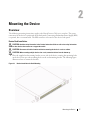 9
9
-
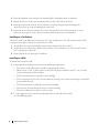 10
10
-
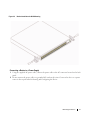 11
11
-
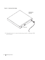 12
12
-
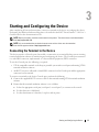 13
13
-
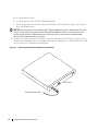 14
14
-
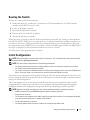 15
15
-
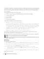 16
16
-
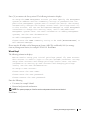 17
17
-
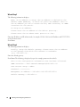 18
18
-
 19
19
-
 20
20
-
 21
21
-
 22
22
-
 23
23
-
 24
24
-
 25
25
-
 26
26
-
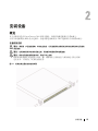 27
27
-
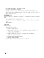 28
28
-
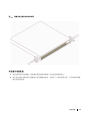 29
29
-
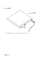 30
30
-
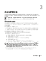 31
31
-
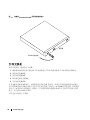 32
32
-
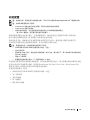 33
33
-
 34
34
-
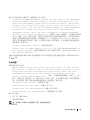 35
35
-
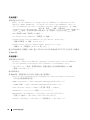 36
36
-
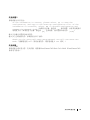 37
37
-
 38
38
-
 39
39
-
 40
40
-
 41
41
-
 42
42
-
 43
43
-
 44
44
-
 45
45
-
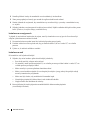 46
46
-
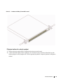 47
47
-
 48
48
-
 49
49
-
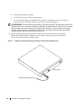 50
50
-
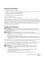 51
51
-
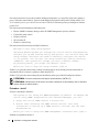 52
52
-
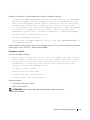 53
53
-
 54
54
-
 55
55
-
 56
56
-
 57
57
-
 58
58
-
 59
59
-
 60
60
-
 61
61
-
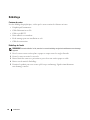 62
62
-
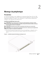 63
63
-
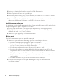 64
64
-
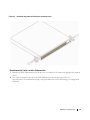 65
65
-
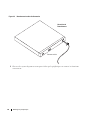 66
66
-
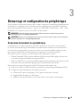 67
67
-
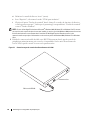 68
68
-
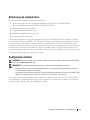 69
69
-
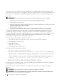 70
70
-
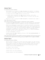 71
71
-
 72
72
-
 73
73
-
 74
74
-
 75
75
-
 76
76
-
 77
77
-
 78
78
-
 79
79
-
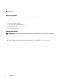 80
80
-
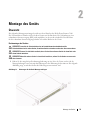 81
81
-
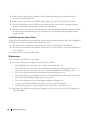 82
82
-
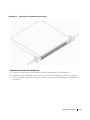 83
83
-
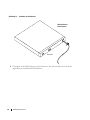 84
84
-
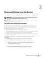 85
85
-
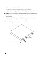 86
86
-
 87
87
-
 88
88
-
 89
89
-
 90
90
-
 91
91
-
 92
92
-
 93
93
-
 94
94
-
 95
95
-
 96
96
-
 97
97
-
 98
98
-
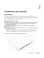 99
99
-
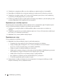 100
100
-
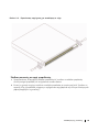 101
101
-
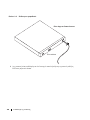 102
102
-
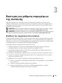 103
103
-
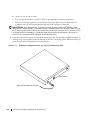 104
104
-
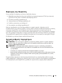 105
105
-
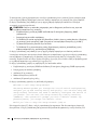 106
106
-
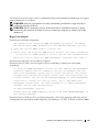 107
107
-
 108
108
-
 109
109
-
 110
110
-
 111
111
-
 112
112
-
 113
113
-
 114
114
-
 115
115
-
 116
116
-
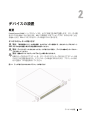 117
117
-
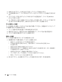 118
118
-
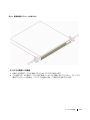 119
119
-
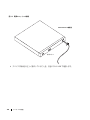 120
120
-
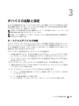 121
121
-
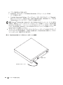 122
122
-
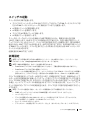 123
123
-
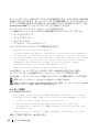 124
124
-
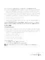 125
125
-
 126
126
-
 127
127
-
 128
128
-
 129
129
-
 130
130
-
 131
131
-
 132
132
-
 133
133
-
 134
134
-
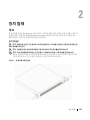 135
135
-
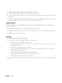 136
136
-
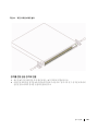 137
137
-
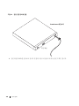 138
138
-
 139
139
-
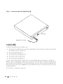 140
140
-
 141
141
-
 142
142
-
 143
143
-
 144
144
-
 145
145
-
 146
146
-
 147
147
-
 148
148
-
 149
149
-
 150
150
-
 151
151
-
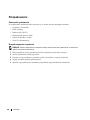 152
152
-
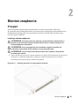 153
153
-
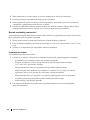 154
154
-
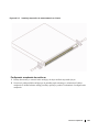 155
155
-
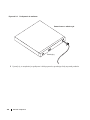 156
156
-
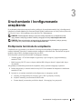 157
157
-
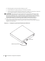 158
158
-
 159
159
-
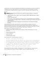 160
160
-
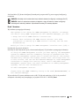 161
161
-
 162
162
-
 163
163
-
 164
164
-
 165
165
-
 166
166
-
 167
167
-
 168
168
-
 169
169
-
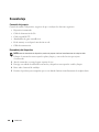 170
170
-
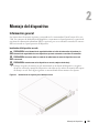 171
171
-
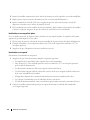 172
172
-
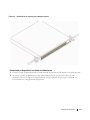 173
173
-
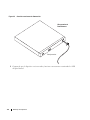 174
174
-
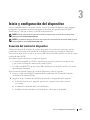 175
175
-
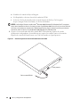 176
176
-
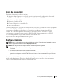 177
177
-
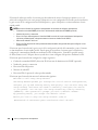 178
178
-
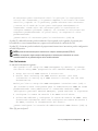 179
179
-
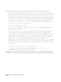 180
180
-
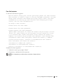 181
181
-
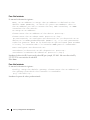 182
182
-
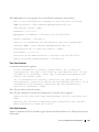 183
183
-
 184
184
-
 185
185
-
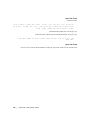 186
186
-
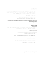 187
187
-
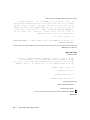 188
188
-
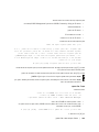 189
189
-
 190
190
-
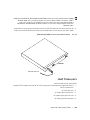 191
191
-
 192
192
-
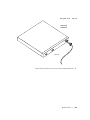 193
193
-
 194
194
-
 195
195
-
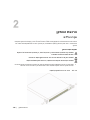 196
196
-
 197
197
-
 198
198
-
 199
199
-
 200
200
-
 201
201
-
 202
202
-
 203
203
-
 204
204
-
 205
205
-
 206
206
-
 207
207
-
 208
208
-
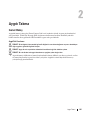 209
209
-
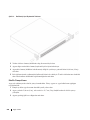 210
210
-
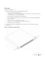 211
211
-
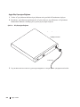 212
212
-
 213
213
-
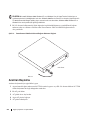 214
214
-
 215
215
-
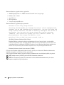 216
216
-
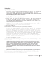 217
217
-
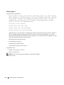 218
218
-
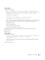 219
219
-
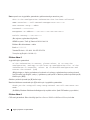 220
220
-
 221
221
-
 222
222


