Jensen 72SS304DX Instrucciones de operación
- Categoría
- Soportes de TV
- Tipo
- Instrucciones de operación

INSTALLATION INSTRUCTIONS
Fig. 3
Fig. 1
Fig. 2
Insert screw
through clear
plastic base
Fig. 5
Snap on Cover
Cover
Base
Screw
Wall
Opening
Cabinet
Body
Fig. 4
Mounting
Sc
rews
Mounting
sc
rewinto
mounting
hole
4. Prepare the mounting screws by placing the screws into the
clear
plastic bases. (Fig. 2)
5. Note: For ease of installation, an additional person is
recommended.Inse
rt cabinet into wall opening. (Fig.3) Ensure
the
cabinet is plumb and level. If necessary use a carpenter’s
level and shim corners of cabinet. Secure the wall studs
through
the four (4) mounting holes inside cabinet, using the
scr
ews that have been placed into the plastic bases. (Fig. 4)
Do not over tighten the mounting screws as the body side wall
may bend and prevent proper shelf installation. Only tighten
until
they are flush with the body.
6. Snap the screw covers over the screw bases. (Fig. 5)
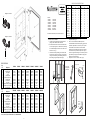
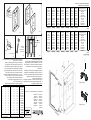
INSTALLATION of CABINET
1. Carefully remove all packing material. Place hardware
pa
ckages, shelves and door aside until needed.
2. Determine desired location of cabinet on wall. Mark wall
to
show wall opening size (see dimension chart). Generally,
the
recommended height to the center of the cabinet is 64”
from
the floor. (Fig. 1)
3. CAUTION: Wall studs, plumbing or electrical lines that
inter
fere must be removed or relocated. Cut wall opening,
being
careful not to damage the surrounding wall surface.
Inse
rt framing to support all plaster board edges.
72-325-03E
MODEL:
72WH244,
72WH244D
72WH246
, 72WH246D
72WH244
F, 72SS244DF
72WH246
F, 72SS246DF
72SS244
D, 72WH244DF
72SS246
D, 72WH246DF
RECESSED MOUNTE
D, STEEL BATH CABINETS
Bisagra de 125 Grados
10
Bisagra de 170 Grados
11
8 1
MODEL
NO
. W H D W H D
72WH24
4 14 ¼ 24 4 15 25 5
72WH246 14 ¼ 24 6 15 25 7
72WH244
F 14 ¼ 24 4 15 25 5
72WH246F 14 ¼ 24 6 15 25 7
72SS244
D 14 ¼ 24 4 15 25 5
72SS246D 14 ¼ 24 6 15 25 7
72WH244D 14 ¼ 24 4 15 25 5
72WH246
D 14 ¼ 24 6 15 25 7
72SS244DF 14 ¼ 24 4 15 25 5
72SS246DF 14 ¼ 24 6 15 25 7
72WH244D
F 14 ¼ 24 4 15 25 5
72WH246DF 14 ¼ 24 6 15 25 7
72SS304D 23 ¼ 29 4 24 30 5
72SS304D
F 23 ¼ 29 4 24 30 5
72WH304D 23 ¼ 29 4 24 30 5
72WH304D
F 23 ¼ 29 4 24 30 5
WALL OPENIN
G OVERALL SIZE
72SS304D, 72SS304DF
72WH304D,
72WH304DF
Key
No. Descripcion
72WH24
4 72WH244F 72WH244D 72WH244DF 72WH246D 72WH246DF 72SS244D
1
Ensamblaje De la Puert
a JRPWH24 JRPWH24F JRPWH24D JRPWH24DF JRPWH24D JRPWH24DF JRPBK24D
2
Montaje de bisagr
a JRP587 JRP587 JRP586D JRP586D JRP586D JRP586D JRP586D
3
Tornillo, bisagr
a 10-163-01 10-163-01 10-163-01 10-163-01 10-163-01 10-163-01 10-163-01
4
Tapone
s 29-826-01 29-826-01 29-826-01 29-826-01 29-826-01 29-826-01 29-826-02
5
Cubierta del tornillo 29-827-01 29-827-01 29-827-01 29-827-01 29-827-01 29-827-01 29-827-02
6
Tornillo de montaje #8 x 1 1/2* * * * * * * *
7
Soporte de estant
e 29-842-01 29-842-01 29-842-01 29-842-01 29-842-01 29-842-01 29-842-02
8
Estante de vidri
o J3116801 J3116801 J3116801 J3116801 J3117101 J3117101 J3116801
9
Tira de Topes 111-695-01 111-695-01 111-695-01 111-695-01 111-695-01 111-695-01 111-695-01
10
Cubierta De la Bisagra (125 grados
) 42-596-01 42-596-01 none none none none none
11
El Sujetador negro (170 grados
) none none 42-594-01 42-594-01 42-594-01 42-594-01 42-594-01
Bolsa de Accesorio
s J2620501 J2620501 J2620501 J2620501 J2620501 J2620501 J2620502
Key
No
. Descripcion
72SS244D
F 72SS246D 72SS246DF 72SS304D 72SS304DF 72WH304D 72WH304DF
1
Ensamblaje De la Puert
a JRPBK24DF JRPBK24D JRPBK24DF J10767603BK J10767604BK J10767603BK J10767604BK
2
Montaje de bisagr
a JRP586D JRP586D JRP586D JRP587 JRP587 JRP587 JRP587
3
Tornillo, bisagr
a 10-163-01 10-163-01 10-163-01 10-163-01 10-163-01 10-163-01 10-163-01
4
Tapone
s 29-826-02 29-826-02 29-826-02 29-826-02 29-826-02 29-826-01 29-826-01
5
Cubierta del tornill
o 29-827-02 29-827-02 29-827-02 29-827-02 29-827-02 29-827-01 29-827-01
6
Tornillo de montaje #8 x 1 1/2
* * * * * * * *
7
Soporte de estant
e 29-842-02 29-842-02 29-842-02 29-842-02 29-842-02 29-842-01 29-842-01
8
Estante de vidri
o J3116801 J3117101 J3117101 J3119901 J3119901 J3119901 J3119901
9
Tira de Topes 111-695-01 111-695-01 111-695-01 111-695-04 111-695-04 111-695-04 111-695-04
10
Cubierta De la Bisagra (125 grados
) none none none 42-586-01 42-586-01 42-586-01 42-586-01
11
El Sujetador negro (170 grados
) 42-594-01 42-594-01 42-594-01
Bolsa de Accesorio
s J2620502 J2620502 J2620502 J2620502 J2620502 J2620501 J2620501
* Ferreteria estandar - puede ser comprado localmente.
Pida los piezas de reemplazo por "NUMERO de PIEZA" - No por el "NUMERO DOMINANTE
"
PIEZAS DE SERVICIO
none none none none

2
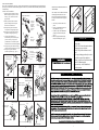
Fig. 11
170 Degree Hinge
This screw for
up and down
adjustments
Thi
s screw
for depth
adjustments
This screw
for left and right
adjustments
Fig. 9
Hook bottom of
hinge into place
on the b
racket
Press down
on hing
e until it
clips in place
17
0 Degree Hinge
Mounted t
o Cabinet
Press
down to
snap into
plac
e.
Press in
lever, then
lift up on
clip to
release
hinge.
Fig. 10
125 Degree Hinge
Thi
s screw for
up and down
adjustment
Thi
s screw
for depth
adjustment
Thi
s screw
for left and right
adjustment
Fig. 12
Hinge Cover
Fig. 7
170 Degree Hinge
Mounted to Door
Fig. 6
125 Degree Hinge
Mounted to Door
FAMILIARIZE YOURSELF WITH HINGE PRIOR TO MOUNTING.
bottom
vi
ew
The bar on
the bottom
of the hinge
slides into
the slot on
the b
racket.
125 Degree Hinge
170 Degree Hinge
bottom
vi
ew
TO REMOVE HINGE
Fig. 8
125 Degree Hinge
mounted to Cabinet
Hook bottom of
hinge int
o place
on the b
racket
Press down
on hinge until
it clips in place
Limit Clip
170
De
gree
Hinge
Fig. 13
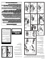
INSTALLATION of DOORS
1. Remove hinges and screws from hardware
bag
. Mount hinge unit on door as shown in
Fig. 6 and Fig. 7 securing with screws provided.
2. Install the door by inserting door side of the
hinge into
the bracket on the body as shown;
A) 125 degree hinge
Inse
rt door side of clip hinge as shown
in
Fig. 8
B) 170 degree hinge
Inse
rt door side of clip hinge as shown
in
Fig. 9
3. Check door for proper alignment. If the door
needs
to be adjusted please refer to the
adjustment
procedures in Fig. 10 and Fig. 11.
Door
edges should be aligned with to the face
of
the body.
4. 125 degree hinge only:
Snap
on hinge cover plate. (Fig. 12)
5. 170 degree hinge only:
Snap on the
black limit clip. (Fig.13)
7
Fig. 14 Fig. 15
INSTALACION de ESTANTES Y TAPONES
Nota: Revise detenidamente la ubicacion deseada
para el estante. Los tapones de los hoyos son
dificiles de quitar una vez metidos, es importante
localizar la ubicacion del estante antes de instalar los
tapones.
1. Seleccione el lugar deseado de los estantes.
2. Ponga dos (2) soportes a cada lado de la ubicacion
deseada. (Fig. 14)
3. Ponga los estantes sobre los soportes, presione
y asi quedara el estante fijo en su lugar.
(Fig.14)
4. Saque los tapones de la bolsa y
coloquelos en los agujeros
restantes. (Fig. 15)
No utilize limpiadores con solucion a base de
• Utilice solamente agua tibia y un trapo limpio,
suave y sin pelusa.
•
ammoniaco, vinagre o cloro.
• No utilize limpiadores en polvo o fibras de
acero.
• Nunca rocie el limpiador directamente en el
espejo, especialmente en los bordes y la
cubierta el la parte posterior. Aplique el
limpiador al trapo y limpie. Seque a fondo.
• Mantenga el espejo seco. Un bano bien
ventilado es importante.
CUIDADO DEL ESPEJO
ATTN: INSTALLER
DO NOT OVER TORQUE (TIGHTEN) HINGE MOUNTING SCREWS. MANUALLY SCREW IN WITH PHILLIPS SCREW DRIVER
UNTIL THE SCREW FEELS SECURE IN THE RIVET. IF USING A POWER DRILL, SET MAXIMUM TORQUE SETTING TO #5.
OVERTIGHTENING THE SCREWS MAY/WILL CAUSE THE RIVET NUT TO LOOSEN FROM THE UNDERSIDE.

Fig. 10
Fig. 12
Fig. 7
Fig. 6
Bisagra de 170 grados
montada a la pue
rta
Bisagra de 125 grados
montada a la pue
rta
Bisagra de 125 grados
montade a la pue
rta
Bisagra de 170 Grados
Ajustes de arriba hacia
abajo
Ajuste de profundidad
6
Fig. 11
Presione
pa
ra ponerlo
en el lugar.
Presione el
nivelador despues
levante el clip
para liberar la
bisagra
FAMILIARICEZE CON LA BISAGRA ANTES DE MONTARLA.
Vista
inferior.
La barra en
la parte de
abajo de la
bisagra se
resbala
en la
ranura del
soporte.
Bisagra de 125 Grados
Bisagra de 170 grados
Vista
inferior.
PARA QUITAR LAS BISAGRAS
Fig. 9
Fig. 8
el sujetador
ne
gro
Bisagra de 170 grados
montada a la pue
rta
Presione la bisagra hasta que
quede sujeto
Bisagra de 125 grados
montada en el gabinete
Presione la bisagra hasta
que quede sujeto
Ajuste la parte inferior de
la bisagra en el soporte
Bisagra
de 170
grados
Enganche el fondo de
la bisagra en su lugar
en el sopo
rte
Fig. 13
3
INSTALLATION of SHELVES, HOLE PLUGS
AND
BUMPERS
Note: Carefully review the shelf location desired.
The hole plugs are difficult to remove once
inserted so it is important to locate the shelves
in the proper location before the hole plugs are
installed.
1. Select where you want the shelves to be
placed.
2. Insert two (2) shelf brackets at each end
of the shelf location. (Fig. 14)
3. Set shelves in place on the shelf brackets,
pressing down on shelf to lock in place.
(Fig. 14)
4. Remove hole plugs from hardware bag
an
d place in remaining holes. ( Fig. 15)
Fig. 15Fig. 14
DO NOT USE cleaners that contain solutions
• Use only clean warm water and a clean, soft,
lint-free cloth.
•
of ammonia, vinegar, or chlorine.
• DO NOT USE powdered cleansers or steel
wool.
• Never spray cleaning agent directly on mirror
especially on exposed edges and mirror
backing. Apply cleaner to soft cloth and wipe
mirror. Dry mirror throughly.
• Keep mirror dry. A well ventilated bath
room is important.
MIRROR CARE
Cubierta de la bisagra
Ajuste de izquierda a derecha
Ajustes de arriba hacia
abajo
Ajuste de profundidad
Ajuste de izquierda a derecha
INSTALACION de PUERTAS
1. Saque las bisagras y tornillos de la bolsa.
Monte
la bisagra en la puerta de acuerdo
a la Fig. 6 y Fig 7. Usando los tornillos
proporcionados.
2. Instale la puerta metiendo el lado de la
puerta
de la bisagra dentro del soporte
de acuerdo con lo demostrado.
A)
Bisagra de 125 grados. Meta el lado
de
la puerta de la bisagra segun la Fig. 8
B) Bisagra de 170 grados. Meta el lado de
la puerta de la bisagra segun la Fig. 9
3.
Asegurese que la alineacion sea
adecuada.
Si la puerta necesita un ajuste,
por favor vea la Fig. 10 y ll para los
procedi
mientos. Los bordes de la puerta
deben de alinear con la caratula del gabinete.
4. Bisagra
de 125 grados solamente: Ponga y
presione la cubierta de la bisagra. ( Fig. 12)
5. Bisagra de 170 grados solamente:
Abroche el sujetador negro. . (Fig. 13)
ATENCION INSTALADORES:
De no apretar los tornillos de mas en la visagra , porfavor de aserlo manual mente con un desarmadorde crus hasta que usted piense
que esta seguro. Si usted husa un taladro sin cable apliquelo en el numero #5. Apretandolos tornillos demasiado apretado podra safarse
el tornillo de abajo.

170 degree hinge
11
5
Fig. 1
Aproximadamente
163cm del piso
Fig. 2
Meta el tornillo
atravez de la base
de plastico
transparente
Fig. 5
Cubierta
Base
Tornillo
Fig. 3
Abertura
de la
pared
Cuerpo
del
gabinete
Fig. 4
Tornillos
de
montaje
Tornillos de
montaje en
el agujero
de montaje
125 degree hinge
10
Cubierta a presion
INSTALACION del GABINETE
1. Quite cuidadosa
mente todo el material del empaquetado.
Coloque
la puerta, los estantes y el paquete de herramientas
a un lado hasta que se necesite.
2. Deter
mine el lugar en la pared para el gabinete.
Marque
la pared para demostrar tamano de la abertura de
la pared (vease la
grafica de dimensiones). Generalmente,
la
altura recomendada son 163cm del centro del gabinete
hacia el suelo.
3. PRE
CAUCION: Lineas electricas o plomeria que
interfieran,
deberan de ser removidas o colocadas en otro
lugar. Corte la abertura de la pared, con cuidado de no
danar
la pared de alrededor. Meta o ponga el enmarco
para
reforzar los bordes de yeso.
4.
Prepare los tornillos de montaje colocando el tornillo
en
la base de plastico. (Fig. 2)
5. Nota: Para mas facilidad en la instalacion, se
reco
miendan dos personas. Meta el gabinete en la
abertura
de la pared. (Fig. 3) Asegurese que este vertical
y al nivel. Si es necesario, rebaje las esquinas del gabinete.
Asegure la pared atravez de los cuatro (4) hoyos para
montar
que se encuentran dentro deel gabinete usando los
tornillos
que estan dentro de las bases de plastico. (Fig 4)
No ap
riete excesivamente los tornillos de montaje ya que
la parte lateral se puede doblar y prevenir la instalcion
adecuada de los estantes. Apriete hasta que los tornillos
esten parejos con el gabinete.
6.
Encaje a presion las tapas sobre la cabeza del tornillo. (Fig.5)
INSTRUCCIONES DE INSTALACION
GABINETE DE ACERO EMPOTRADO EN LA PARED
4
NUMERO DE
72WH24
4 14 ¼ 24 4 15 25 5
72WH24
6 14 ¼ 24 6 15 25 7
72WH244
F 14 ¼ 24 4 15 25 5
72WH246
F 14 ¼ 24 6 15 25 7
72SS244
D 14 ¼ 24 4 15 25 5
72SS246D 14 ¼ 24 6 15 25 7
72WH244
D 14 ¼ 24 4 15 25 5
72WH246
D 14 ¼ 24 6 15 25 7
72SS244D
F 14 ¼ 24 4 15 25 5
72SS246DF 14 ¼ 24 6 15 25 7
72WH244D
F 14 ¼ 24 4 15 25 5
72WH246D
F 14 ¼ 24 6 15 25 7
72SS304D 23 ¼ 29 4 24 30 5
72SS304D
F 23 ¼ 29 4 24 30 5
72WH304D 23 ¼ 29 4 24 30 5
72WH304D
F 23 ¼ 29 4 24 30 5
ABERTURA DE LA PARE
D TOMANO TOTAL
MODELO:
72WH244,
72WH244D
72WH246
, 72WH246D
72WH244
F, 72SS244DF
72WH246
F, 72SS246DF
72SS244
D, 72WH244DF
72SS246
D, 72WH246DF
72SS304D, 72SS304DF
72WH304D, 72WH304DF
Key
No
. Description
72WH244 72WH244F 72WH244D 72WH244DF 72WH246D 72WH246DF 72SS244D
1
Door Assembl
y JRPWH24 JRPWH24F JRPWH24D JRPWH24DF JRPWH24D JRPWH24DF JRPBK24D
2
Hinge Assy (Door
) JRP587 JRP587 JRP586D JRP586D JRP586D JRP586D JRP586D
3
Hinge Scre
w 10-163-01 10-163-01 10-163-01 10-163-01 10-163-01 10-163-01 10-163-01
4
Hole Plu
g 29-826-01 29-826-01 29-826-01 29-826-01 29-826-01 29-826-01 29-826-02
5
Screw Cove
r 29-827-01 29-827-01 29-827-01 29-827-01 29-827-01 29-827-01 29-827-02
6
Mountin
g
Screw #8 x 1-1/2
* * * * * * *
7
Shelf Support
s 29-842-01 29-842-01 29-842-01 29-842-01 29-842-01 29-842-01 29-842-02
8
Glass Shel
f J3116801 J3116801 J3116801 J3116801 J3117101 J3117101 J3116801
9
Bumper Stri
p 111-695-01 111-695-01 111-695-01 111-695-01 111-695-01 111-695-01 111-695-01
10
Hinge Cover (125 degree hinge) 42-596-01 42-596-01 none none none none none
11
Limit Clip (170 degree hinge
) none none 42-594-01 42-594-01 42-594-01 42-594-01 42-594-01
Hardware Bag Assembly J2620501 J2620501 J2620501 J2620501 J2620501 J2620501 J2620502
Key
No
. Description
72SS244D
F 72SS246D 72SS246DF 72SS304D 72SS304DF 72WH304D 72WH304DF
1
Door Assembl
y JRPBK24DF JRPBK24D JRPBK24DF J10767603BK J10767604BK J10767603BK J10767604BK
2
Hinge Assy (Door
) JRP586D JRP586D JRP586D JRP587 JRP587 JRP587 JRP587
3
Hinge Scre
w 10-163-01 10-163-01 10-163-01 10-163-01 10-163-01 10-163-01 10-163-01
4
Hole Plu
g 29-826-02 29-826-02 29-826-02 29-826-02 29-826-02 29-826-01 29-826-01
5
Screw Cove
r 29-827-02 29-827-02 29-827-02 29-827-02 29-827-02 29-827-01 29-827-01
6
Mountin
g
Screw #8 x 1
1
/
2
* * * * * * *
7
Shelf Support
s 29-842-02 29-842-02 29-842-02 29-842-02 29-842-02 29-842-01 29-842-01
8
Glass Shel
f J3116801 J3117101 J3117101 J3119901 J3119901 J3119901 J3119901
9
Bumper Stri
p 111-695-01 111-695-01 111-695-01 111-695-04 111-695-04 111-695-04 111-695-04
10
Hinge Cover (125 degree hinge
) none none none 42-596-01 42-596-01 42-596-01 42-596-01
11
Limit Clip (170 degree hinge) 42-594-01 42-594-01 42-594-01 none none none none
Hardware Bag Assembl
y J2620502 J2620502 J2620502 J2620502 J2620502 J2620501 J2620501
* Standard Hardware - may be purchased locally
.
Order Replacement parts by "Part Number" - not by "Key No.
"
SERVICE PARTS
W H D
MODELO
W H D
Transcripción de documentos
INSTALLATION INSTRUCTIONS Bisagra de 125 Grados 10 MODEL: 72WH244, 72WH246, 72WH244F, 72WH246F, 72SS244D, 72SS246D, 72SS304D, 72WH304D, 72WH244D 72WH246D 72SS244DF 72SS246DF 72WH244DF 72WH246DF 72SS304DF 72WH304DF RECESSED MOUNTED, STEEL BATH CABINETS Bisagra de 170 Grados MODEL NO. 72WH244 72WH246 72WH244F 72WH246F 72SS244D 72SS246D 72WH244D 72WH246D 72SS244DF 72SS246DF 72WH244DF 72WH246DF 72SS304D 72SS304DF 72WH304D 72WH304DF 4. INSTALLATION of CABINET 1. Carefully remove all packing material. Place hardware 5. packages, shelves and door aside until needed. 2. Determine desired location of cabinet on wall. Mark wall to show wall opening size (see dimension chart). Generally, the recommended height to the center of the cabinet is 64” from the floor. (Fig. 1) 3. CAUTION: Wall studs, plumbing or electrical lines that interfere must be removed or relocated. Cut wall opening, being careful not to damage the surrounding wall surface. Insert framing to support all plaster board edges. 6. 11 WALL OPENING W H 14 ¼ 24 14 ¼ 24 14 ¼ 24 14 ¼ 24 14 ¼ 24 14 ¼ 24 14 ¼ 24 14 ¼ 24 14 ¼ 24 14 ¼ 24 14 ¼ 24 14 ¼ 24 23 ¼ 29 23 ¼ 29 23 ¼ 29 23 ¼ 29 1 2 3 4 5 6 7 8 9 10 11 Key No. 1 2 3 4 5 6 7 8 9 10 11 Descripcion Ensamblaje De la Puerta Montaje de bisagra Tornillo, bisagra Tapones Cubierta del tornillo Tornillo de montaje #8 x 1 1/2* Soporte de estante Estante de vidrio Tira de Topes Cubierta De la Bisagra (125 grados) El Sujetador negro (170 grados) Bolsa de Accesorios Descripcion Ensamblaje De la Puerta Montaje de bisagra Tornillo, bisagra Tapones Cubierta del tornillo Tornillo de montaje #8 x 1 1/2* Soporte de estante Estante de vidrio Tira de Topes Cubierta De la Bisagra (125 grados) El Sujetador negro (170 grados) Bolsa de Accesorios 72WH244 72WH244F 72WH244D 72WH244DF 72WH246D 72WH246DF 72SS244D JRPWH24 JRP587 10-163-01 29-826-01 29-827-01 * 29-842-01 J3116801 111-695-01 42-596-01 none J2620501 JRPWH24F JRP587 10-163-01 29-826-01 29-827-01 * 29-842-01 J3116801 111-695-01 42-596-01 none J2620501 JRPWH24D JRP586D 10-163-01 29-826-01 29-827-01 * 29-842-01 J3116801 111-695-01 none 42-594-01 J2620501 JRPWH24DF JRP586D 10-163-01 29-826-01 29-827-01 * 29-842-01 J3116801 111-695-01 none 42-594-01 J2620501 JRPWH24D JRP586D 10-163-01 29-826-01 29-827-01 * 29-842-01 J3117101 111-695-01 none 42-594-01 J2620501 JRPWH24DF JRP586D 10-163-01 29-826-01 29-827-01 * 29-842-01 J3117101 111-695-01 none 42-594-01 J2620501 JRPBK24D JRP586D 10-163-01 29-826-02 29-827-02 * 29-842-02 J3116801 111-695-01 none 42-594-01 J2620502 72SS244DF 72SS246D 72SS246DF 72SS304D 72SS304DF 72WH304D 72WH304DF JRPBK24DF JRP586D 10-163-01 29-826-02 29-827-02 * 29-842-02 J3116801 111-695-01 none 42-594-01 J2620502 JRPBK24D JRP586D 10-163-01 29-826-02 29-827-02 * 29-842-02 J3117101 111-695-01 none 42-594-01 J2620502 JRPBK24DF JRP586D 10-163-01 29-826-02 29-827-02 * 29-842-02 J3117101 111-695-01 none 42-594-01 J2620502 J10767603BK JRP587 10-163-01 29-826-02 29-827-02 * 29-842-02 J3119901 111-695-04 42-586-01 none J2620502 J10767604BK JRP587 10-163-01 29-826-02 29-827-02 * 29-842-02 J3119901 111-695-04 42-586-01 none J2620502 J10767603BK JRP587 10-163-01 29-826-01 29-827-01 * 29-842-01 J3119901 111-695-04 42-586-01 none J2620501 J10767604BK JRP587 10-163-01 29-826-01 29-827-01 * 29-842-01 J3119901 111-695-04 42-586-01 none J2620501 OVERALL SIZE H 25 25 25 25 25 25 25 25 25 25 25 25 30 30 30 30 Fig. 5 PIEZAS DE SERVICIO Key No. W 15 15 15 15 15 15 15 15 15 15 15 15 24 24 24 24 Prepare the mounting screws by placing the screws into the clear plastic bases. (Fig. 2) Note: For ease of installation, an additional person is recommended.Insert cabinet into wall opening. (Fig.3) Ensure the cabinet is plumb and level. If necessary use a carpenter’s level and shim corners of cabinet. Secure the wall studs through the four (4) mounting holes inside cabinet, using the screws that have been placed into the plastic bases. (Fig. 4) Do not over tighten the mounting screws as the body side wall may bend and prevent proper shelf installation. Only tighten until they are flush with the body. Snap the screw covers over the screw bases. (Fig. 5) Fig. 2 Fig. 1 D 4 6 4 6 4 6 4 6 4 6 4 6 4 4 4 4 Snap on Cover Insert screw through clear plastic base Cover Screw Base Fig. 4 Fig. 3 Wall Opening Mounting Screws Cabinet Body Mounting screwinto mounting hole * Ferreteria estandar - puede ser comprado localmente. Pida los piezas de reemplazo por "NUMERO de PIEZA" - No por el "NUMERO DOMINANTE" 72-325-03E 8 1 D 5 7 5 7 5 7 5 7 5 7 5 7 5 5 5 5 ATTN: INSTALLER DO NOT OVER TORQUE (TIGHTEN) HINGE MOUNTING SCREWS. MANUALLY SCREW IN WITH PHILLIPS SCREW DRIVER UNTIL THE SCREW FEELS SECURE IN THE RIVET. IF USING A POWER DRILL, SET MAXIMUM TORQUE SETTING TO #5. OVERTIGHTENING THE SCREWS MAY/WILL CAUSE THE RIVET NUT TO LOOSEN FROM THE UNDERSIDE. INSTALLATION of DOORS 1. Remove hinges and screws from hardware bag. Mount hinge unit on door as shown in Fig. 6 and Fig. 7 securing with screws provided. 2. Install the door by inserting door side of the hinge into the bracket on the body as shown; A) 125 degree hinge Insert door side of clip hinge as shown in Fig. 8 B) 170 degree hinge Insert door side of clip hinge as shown in Fig. 9 3. Check door for proper alignment. If the door needs to be adjusted please refer to the adjustment procedures in Fig. 10 and Fig. 11. Door edges should be aligned with to the face of the body. 4. 125 degree hinge only: Snap on hinge cover plate. (Fig. 12) 170 degree hinge only: Snap on the black limit clip. (Fig.13) FAMILIARIZE YOURSELF WITH HINGE PRIOR TO MOUNTING. 125 Degree Hinge bottom view The bar on the bottom of the hinge slides into the slot on the bracket. 170 Degree Hinge bottom view Press down to snap into place. INSTALACION de ESTANTES Y TAPONES Fig. 14 Nota: Revise detenidamente la ubicacion deseada para el estante. Los tapones de los hoyos son dificiles de quitar una vez metidos, es importante localizar la ubicacion del estante antes de instalar los tapones. 1. Seleccione el lugar deseado de los estantes. 2. Ponga dos (2) soportes a cada lado de la ubicacion deseada. (Fig. 14) 3. Ponga los estantes sobre los soportes, presione y asi quedara el estante fijo en su lugar. (Fig.14) 4. Saque los tapones de la bolsa y coloquelos en los agujeros restantes. (Fig. 15) • • 5. Fig. 6 • TO REMOVE HINGE Press in lever, then lift up on clip to release hinge. 125 Degree Hinge Mounted to Door • • Fig. 13 Fig. 9 170 Degree Hinge Limit Clip Fig. 7 170 Degree Hinge Mounted to Door Fig. 8 125 Degree Hinge mounted to Cabinet 170 Degree Hinge Mounted to Cabinet This screw for up and down adjustments Fig. 11 Hook bottom of hinge into place on the bracket Fig. 15 CUIDADO DEL ESPEJO Utilice solamente agua tibia y un trapo limpio, suave y sin pelusa. No utilize limpiadores con solucion a base de ammoniaco, vinagre o cloro. No utilize limpiadores en polvo o fibras de acero. Nunca rocie el limpiador directamente en el espejo, especialmente en los bordes y la cubierta el la parte posterior. Aplique el limpiador al trapo y limpie. Seque a fondo. Mantenga el espejo seco. Un bano bien ventilado es importante. Hook bottom of hinge into place on the bracket Press down on hinge until it clips in place Press down on hinge until it clips in place Fig. 10 This screw for up and down adjustment Fig. 12 170 Degree Hinge 125 Degree Hinge This screw for depth adjustments This screw for depth adjustment This screw for left and right adjustments This screw for left and right adjustment Hinge Cover 2 7 ATENCION INSTALADORES: De no apretar los tornillos de mas en la visagra , porfavor de aserlo manual mente con un desarmadorde crus hasta que usted piense que esta seguro. Si usted husa un taladro sin cable apliquelo en el numero #5. Apretandolos tornillos demasiado apretado podra safarse el tornillo de abajo. INSTALACION de PUERTAS FAMILIARICEZE CON LA BISAGRA ANTES DE MONTARLA. 1. Saque las bisagras y tornillos de la bolsa. Monte la bisagra en la puerta de acuerdo Bisagra de 125 Grados Bisagra de 170 grados a la Fig. 6 y Fig 7. Usando los tornillos proporcionados. La barra en 2. Instale la puerta metiendo el lado de la la parte de Vista puerta de la bisagra dentro del soporte abajo de la Vista inferior. de acuerdo con lo demostrado. bisagra se inferior. resbala en la A) Bisagra de 125 grados. Meta el lado ranura del de la puerta de la bisagra segun la Fig. 8 soporte. B) Bisagra de 170 grados. Meta el lado de la puerta de la bisagra segun la Fig. 9 3. Asegurese que la alineacion sea adecuada. Si la puerta necesita un ajuste, Presione para ponerlo por favor vea la Fig. 10 y ll para los en el lugar. procedimientos. Los bordes de la puerta INSTALLATION of SHELVES, HOLE PLUGS AND BUMPERS Fig. 14 Fig. 15 Note: Carefully review the shelf location desired. The hole plugs are difficult to remove once inserted so it is important to locate the shelves in the proper location before the hole plugs are installed. 1. Select where you want the shelves to be placed. 2. Insert two (2) shelf brackets at each end of the shelf location. (Fig. 14) 3. Set shelves in place on the shelf brackets, pressing down on shelf to lock in place. (Fig. 14) 4. Remove hole plugs from hardware bag and place in remaining holes. ( Fig. 15) • deben de alinear con la caratula del gabinete. 4. 5. • Bisagra de 125 grados solamente: Ponga y presione la cubierta de la bisagra. ( Fig. 12) Bisagra de 170 grados solamente: Abroche el sujetador negro. . (Fig. 13) PARA QUITAR LAS BISAGRAS Fig. 6 Bisagra de 125 grados montada a la puerta Fig. 13 Fig. 9 Bisagra de 170 grados el sujetador negro Fig. 7 Fig. 8 Bisagra de 170 grados montada a la puerta Bisagra de 125 grados montade a la puerta Ajustes de arriba hacia abajo Ajuste de profundidad • • Enganche el fondo de la bisagra en su lugar en el soporte Bisagra de 170 grados montada a la puerta Ajuste la parte inferior de la bisagra en el soporte Bisagra de 125 grados montada en el gabinete Presione la bisagra hasta que quede sujeto Fig. 10 • Presione el nivelador despues levante el clip para liberar la bisagra Fig. 11 Ajustes de arriba hacia abajo Bisagra de 170 Grados Presione la bisagra hasta que quede sujeto Fig. 12 Ajuste de profundidad Ajuste de izquierda a derecha Ajuste de izquierda a derecha 6 Cubierta de la bisagra 3 MIRROR CARE Use only clean warm water and a clean, soft, lint-free cloth. DO NOT USE cleaners that contain solutions of ammonia, vinegar, or chlorine. DO NOT USE powdered cleansers or steel wool. Never spray cleaning agent directly on mirror especially on exposed edges and mirror backing. Apply cleaner to soft cloth and wipe mirror. Dry mirror throughly. Keep mirror dry. A well ventilated bath room is important. 125 degree hinge 10 MODELO: 72WH244, 72WH246, 72WH244F, 72WH246F, 72SS244D, 72SS246D, 72SS304D, 72WH304D, 72WH244D 72WH246D 72SS244DF 72SS246DF 72WH244DF 72WH246DF 72SS304DF 72WH304DF GABINETE DE ACERO EMPOTRADO EN LA PARED 170 degree hinge 11 SERVICE PARTS Key No. 1 2 3 4 5 6 7 8 9 10 11 Description Door Assembly Hinge Assy (Door) Hinge Screw Hole Plug Screw Cover Mounting Screw #8 x 1-1/2 Shelf Supports Glass Shelf Bumper Strip Hinge Cover (125 degree hinge) Limit Clip (170 degree hinge) Hardware Bag Assembly Key No. 1 2 3 4 5 6 7 8 9 10 11 Description Door Assembly Hinge Assy (Door) Hinge Screw Hole Plug Screw Cover Mounting Screw #8 x 1 1/2 Shelf Supports Glass Shelf Bumper Strip Hinge Cover (125 degree hinge) Limit Clip (170 degree hinge) Hardware Bag Assembly 72WH244 72WH244F 72SS246D 72SS244DF JRPWH24F JRP587 10-163-01 29-826-01 29-827-01 * 29-842-01 J3116801 111-695-01 42-596-01 none J2620501 JRPWH24 JRP587 10-163-01 29-826-01 29-827-01 * 29-842-01 J3116801 111-695-01 42-596-01 none J2620501 JRPBK24DF JRP586D 10-163-01 29-826-02 29-827-02 * 29-842-02 J3116801 111-695-01 none 42-594-01 J2620502 JRPBK24D JRP586D 10-163-01 29-826-02 29-827-02 * 29-842-02 J3117101 111-695-01 none 42-594-01 J2620502 72WH244D JRPWH24D JRP586D 10-163-01 29-826-01 29-827-01 * 29-842-01 J3116801 111-695-01 none 42-594-01 J2620501 72SS246DF JRPBK24DF JRP586D 10-163-01 29-826-02 29-827-02 * 29-842-02 J3117101 111-695-01 none 42-594-01 J2620502 72WH244DF JRPWH24DF JRP586D 10-163-01 29-826-01 29-827-01 * 29-842-01 J3116801 111-695-01 none 42-594-01 J2620501 72SS304D J10767603BK JRP587 10-163-01 29-826-02 29-827-02 * 29-842-02 J3119901 111-695-04 42-596-01 none J2620502 72WH246D JRPWH24D JRP586D 10-163-01 29-826-01 29-827-01 * 29-842-01 J3117101 111-695-01 none 42-594-01 J2620501 72SS304DF J10767604BK JRP587 10-163-01 29-826-02 29-827-02 * 29-842-02 J3119901 111-695-04 42-596-01 none J2620502 72WH246DF JRPWH24DF JRP586D 10-163-01 29-826-01 29-827-01 * 29-842-01 J3117101 111-695-01 none 42-594-01 J2620501 72WH304D J10767603BK JRP587 10-163-01 29-826-01 29-827-01 * 29-842-01 J3119901 111-695-04 42-596-01 none J2620501 NUMERO DE MODELO 72WH244 72WH246 72WH244F 72WH246F 72SS244D 72SS246D 72WH244D 72WH246D 72SS244DF 72SS246DF 72WH244DF 72WH246DF 72SS304D 72SS304DF 72WH304D 72WH304DF INSTALACION del GABINETE 1. Quite cuidadosamente todo el material del empaquetado. Coloque la puerta, los estantes y el paquete de herramientas a un lado hasta que se necesite. 2. Determine el lugar en la pared para el gabinete. Marque la pared para demostrar tamano de la abertura de la pared (vease la grafica de dimensiones). Generalmente, la altura recomendada son 163cm del centro del gabinete hacia el suelo. 3. PRECAUCION: Lineas electricas o plomeria que interfieran, deberan de ser removidas o colocadas en otro lugar. Corte la abertura de la pared, con cuidado de no danar la pared de alrededor. Meta o ponga el enmarco para reforzar los bordes de yeso. Fig. 1 INSTRUCCIONES DE INSTALACION ABERTURA DE LA PARED W H D 14 ¼ 24 4 14 ¼ 24 6 14 ¼ 24 4 14 ¼ 24 6 14 ¼ 24 4 14 ¼ 24 6 14 ¼ 24 4 14 ¼ 24 6 14 ¼ 24 4 14 ¼ 24 6 14 ¼ 24 4 14 ¼ 24 6 23 ¼ 29 4 23 ¼ 29 4 23 ¼ 29 4 23 ¼ 29 4 TOMANO TOTAL W H D 15 25 5 15 25 7 15 25 5 15 25 7 15 25 5 15 25 7 15 25 5 15 25 7 15 25 5 15 25 7 15 25 5 15 25 7 24 30 5 24 30 5 24 30 5 24 30 5 4. Prepare los tornillos de montaje colocando el tornillo en la base de plastico. (Fig. 2) 5. Nota: Para mas facilidad en la instalacion, se recomiendan dos personas. Meta el gabinete en la abertura de la pared. (Fig. 3) Asegurese que este vertical y al nivel. Si es necesario, rebaje las esquinas del gabinete. Asegure la pared atravez de los cuatro (4) hoyos para montar que se encuentran dentro deel gabinete usando los tornillos que estan dentro de las bases de plastico. (Fig 4) No apriete excesivamente los tornillos de montaje ya que la parte lateral se puede doblar y prevenir la instalcion adecuada de los estantes. Apriete hasta que los tornillos esten parejos con el gabinete. 6. Encaje a presion las tapas sobre la cabeza del tornillo. (Fig.5) Fig. 2 Fig. 5 Cubierta a presion 72SS244D JRPBK24D JRP586D 10-163-01 29-826-02 29-827-02 * 29-842-02 J3116801 111-695-01 none 42-594-01 J2620502 Meta el tornillo atravez de la base de plastico transparente Cubierta Tornillo Aproximadamente 163cm del piso Base Fig. 4 Fig. 3 72WH304DF Abertura de la pared J10767604BK JRP587 10-163-01 29-826-01 29-827-01 * 29-842-01 J3119901 111-695-04 42-596-01 none J2620501 Tornillos de montaje Cuerpo del gabinete Tornillos de montaje en el agujero de montaje * Standard Hardware - may be purchased locally. Order Replacement parts by "Part Number" - not by "Key No." 5 4-
 1
1
-
 2
2
-
 3
3
-
 4
4


Jensen 72SS304DX Instrucciones de operación
- Categoría
- Soportes de TV
- Tipo
- Instrucciones de operación