FMI NY100 Instrucciones de operación
- Categoría
- Controles remotos
- Tipo
- Instrucciones de operación

F
TEMP SET
ON
ROOM
OFF
MODE
SET
This remote control transmits signals to the receiver. This remote control
system was developed to provide a safe, reliable and user friendly remote
control system for gas heating appliances. The system can be operated
manually from the remote control. The system operates on radio frequen-
cies (RF) within a 20' range using non-directional signals. The system
operates on one of 1,048,576 security codes that are programed into
the remote control at the factory. The receiver's code must be matched
to that of the remote control prior to use.
IMPORTANT: The remote control will only operate heater if pilot light is
lit and control knob is in the ON position.
REMOTE CONTROL
This remote control system offers the user a battery operated remote
control to power latching solenoids. These latching solenoids are those
used with gas valves in some heater rated gas logs, gas replaces and
other gas heating appliances.
The solenoid circuit uses the battery power from the receiver to operate
the solenoid. The circuit has reversing polarity software which reverses
the positive (+) and negative (-) output of the receiver's battery power
to drive a latching solenoid ON/OFF. The system is controlled by the
remote transmitter.
The remote control operates on 2 AAA 1.5V size alkaline batteries (not
included) that powers the RF signal and LCD screen. Before using
the remote control, alkaline batteries must be installed into the battery
compartments.
IMPORTANT! THIS SHEET REPLACES ALL REMOTE CONTROL
INSTALLATION AND OPERATION INSTRUCTIONS INCLUDED IN
YOUR OWNER'S MANUAL. REFER TO THESE INSTRUCTIONS WHEN
INSTALLINg OR OPERATINg REMOTE CONTROL FEATURES.
MULTI-FUNCTION WIRELESS REMOTE CONTROL SYSTEM FOR OPERATINg A LATCHINg
SOLENOID VALVE, MANUALLY OR WITH A THERMOSTAT FUNCTION
INSTALLATION AND OPERATINg INSTRUCTIONS
If you cannot read or understand these installation instructions, do not attempt to install or operate.
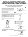
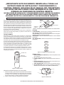
Figure 1 - Remote Control
LCD
Display
Figure 2 - Installing Alkaline batteries in Hand-Held Remote Control
Installing Alkaline Batteries Into Remote
1. Slide down and remove battery cover and insert alkaline batteries into
remote control as shown in Figure 2. It is recommended that ALKA-
LINE batteries always be used for longer battery life and maximum
operational performance.
2. Replace battery cover.
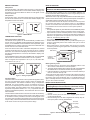
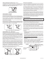
Figure 4 - LCD Display
LCD DISPLAY
1. DISPLAY - Indicates current room temperature.
2. °F OR °C - Indicates degrees Fahrenheit or Celsius.
3. FLAME - Indicates burner valve in operation.
4. ROOM - Indicates remote is in THERMO operation.
5. TEMP - Appears during manual operation.
6. SET - Appears while setting desired temperature in THERMO operation.
Figure 3 - Remote Settings
SETTING 0° F (0° C) SCALE
Factory setting for temperature is 0° F. To change this setting to 0° C,
press ON and OFF buttons on the remote control at the same time. Fol-
low this same procedure to change from 0° C back to 0° F.
For more information, visit www.desatech.com
BUTTONS
ON - Operates unit to on position. Manually operated solenoid ON.
OFF - Operates unit to off position. Manually operated solenoid OFF.
MODE - Changes unit from MANUAL mode to THERMO mode.
SET - Sets temperature in THERMO mode.
AAA
Alkaline
batteries
Battery
Cover
Remote Control
ON Button
F
TEMP SET
ON
ROOM
OFF
MODE
SET
F
TEMP SET
ON
ROOM
OFF
MODE
SET
1
4
6
2
3
5
Figure 5 - Fahrenheit/Celsius
F
TEMPSETROOM

www.desatech.com
122471-01B2
F
TEMPSET
F
TEMPROOM
LEARN
ADJ.
REMOTE
O
FF
MANUAL FUNCTION
ON Operation
Press the ON button. The heater’s ame will come on. During this time
the LCD screen will show ON for 3 seconds then default to display room
temperature and the word TEMP. The ame icon will appear on LCD
screen in ON mode.
OFF Operation
Press the OFF button. The heater’s ame will shut off. During this time
the LCD screen will show OF for 3 seconds then default to display room
temperature and the word TEMP.
THERMOSTAT FUNCTION
Setting Desired Room Temperature
This remote control system can be thermostatically controlled when
remote control is in THERMO mode (ROOM must be displayed on the
screen). To set THERMO mode and desired room temperature, press
the MODE button to until the LCD screen shows the word ROOM. The
remote control is now in thermostat mode.
Press and hold the SET button until desired temperature is reached
(numbers will increase from 45° to 99° then start over at 45°). Release
SET button. The LCD screen will display set temperature for 3 seconds,
then ash set temperature for 3 seconds, then default to display room
temperature.
Press the MODE button to disengage THERMO mode. The word ROOM
will not show on LCD screen when the thermo is not in operation.
Note: The highest SET temperature is 99° F (37° C). The lowest SET
temperature is 45° F (8° C).
REMOTE RECEIVER
REMOTE RECEIVER SHOULD BE POSITIONED OUTSIDE OF
HEATER IN THE MOUNTING BRACKET SHIELD
The remote receiver operates on four 1.5V AA alkaline batteries. It is
recommended that alkaline batteries be used for longer battery life and
maximum microprocessor performance.
IMPORTANT: New or fully charged alkaline batteries are essential to proper
operation of the remote receiver. Latching solenoid power consumption is
substantially higher than standard remote control systems.
Note: The remote receiver will respond to the remote control only when
the 2 position slide button on the remote receiver is in the REMOTE
position. The remote receiver houses the microprocessor that responds
to commands from the remote control to control system operation.
Functions
• The system will operate only if the slide switch is in the REMOTE position
and the remote receiver receives commands from the remote control.
• Upon initial use or after an extended period of no use, the ON button
may have to be pressed for up to three seconds before activating the
solenoid. If the system does not respond to the remote control on
initial use, see Matching Security Codes.
• The system is off when the slide is in the OFF position.
• Position slide switch in the OFF position if you will be away from your
home for an extended period of time. Heater could cycle on and off
at other settings.
• Placing slide switch in the OFF position also functions as a safety
“lock out” by both turning the system OFF and rendering the remote
control inoperative.
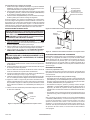
Figure 6 - ON/OFF Modes
Figure 7 - Setting Temperature
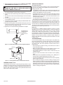
LEARN
Button
(Inside)
Slide Switch
F
TEMP
F
TEMP
Operational Notes
The thermo feature on the remote control operates the appliance when-
ever the room temperature varies a certain number of degrees from
the set temperature. This variation is called the “swing” or Temperature
Differential. The normal operating cycle of an appliance may be 2-4
times per hour depending on how well the room or home is insulated
from cold or drafts. The factory setting for the “swing” number is 2. This
represents a temperature variation of +/- 2° F (1° C) between SET tem-
perature and ROOM temperature, which determines when the heater
will be activated.
The transmitter has ON and OFF manual functions that are activated by
pressing either button on the face of the remote control. When a button
on the remote control is pressed the word ON or OF will appear on the
LCD screen to show while the signal is being sent. Upon initial use, there
may be a delay of three seconds before the remote receiver will respond
to the remote control. This is part of the system’s design.
Frequency
Adjusting
Access Hole
Figure 8 - Remote Receiver
Matching Security Codes
1. Move slide switch on the receiver to the REMOTE position. Code
will not "learn" if slide switch is in the OFF position.
2.
To program remote receiver to learn a new security code, press and release
the LEARN button on the receiver. Receiver will emit a single beep.
3. Press the ON button on the remote control. The receiver will beep 3
times to conrm the security code.
The microprocessor that controls the security code matching procedure
is controlled by a timing function. If you are unsuccessful in matching
the security code on the rst attempt, wait 1 to 2 minutes before trying
again. This delay allows the microprocessor to reset its timer circuitry.
Try up to two or three more times.
INSTALLATION INSTRUCTIONS
Follow instructions in heater owner's manual up to
Installing Remote Control Receiver. Use these instruc-
tions for installing receiver to heater, then continue with
remaining heater installation instructions.
1. Remove front cover of heater (see Installing Heater in your owner's
manual).
2. Remove circular punch out from rear of supplied plastic receiver
mounting bracket/shield.
3. Remove backing from one side of supplied hook and loop tape. At-
tach tape to plastic mounting bracket/shield.
Figure 9 - Remote Receiver Mounting Bracket/Shield
Punch
Out Hole
Hook and
Loop Tape

www.desatech.com
122471-01B 3
R
EM
O
TE
O
FF
L
EARN
AD
J
.
Battery Cover
Receiver
AA Alkaline
batteries
Figure 10 - Installing Remote Receiver Mounting Bracket/Shield
Bracket/Shield on
Outside of Heater
with Opening
Towards Front of
Heater
4. Remove backing from other side of tape and INSTALL ON OUTSIDE
AND UNDERNEATH OF HEATER as shown in Figure 10.
CAUTION: BE SURE TO INSTALL RECEIVER ON
OUTSIDE OF UNIT ONLY. IF INSTALLED INSIDE OF
HEATER, DAMAGE CAN OCCUR.
5. Remove battery compartment cover from remote receiver. Install
new alkaline batteries. Replace battery compartment.
6. Pass remote receiver wires through hole in plastic mounting bracket/
shield.
7. Run wires from control valve solenoid through a vent hole in bottom
of heater.
8. Connect wires from receiver to wires on control valve solenoid (red
to red and black to black).
9. Insert remote receiver into plastic mounting bracket/shield with selec-
tor switch facing front of heater.
10. Bundle wires along bottom of inside heater ensuring they are not in
contact with any burner components. Secure wires to oor of heater
through vent holes with supplied cable tie.
11. Replace front cover after remaining installation is complete.
Figure 11 - Installing Alkaline B atteries into Remote Receiver
TRANSMITTER WALL CLIP
The transmitter can be hung on a wall using the clip provided. If clip is
installed on a solid wood wall, drill 1/8" pilot holes and install with screws
provided. If it is installed on a plaster or wallboard wall, rst drill two 1/4"
holes into wall. Use a hammer to tap in the 2 plastic wall anchors ush
with the wall. Install screws provided.
GENERAL INFORMATION
CP (childproof) Feature
This remote control includes a childproof “lock out” feature that allows the
user to lock out operation of the appliance from the remote control.
Setting “Lock Out” - (CP)
• To activate the lock out feature, press and hold the ON button and
the MODE button at the same time for 5 seconds. The letters CP will
appear in the TEMP frame on the LCD screen.
• To disengage the lock out, press and hold the ON button and the
MODE button at the same time for 5 seconds and the letters CP will
disappear from the LCD screen. The remote control will return to its
normal operating condition.
• To verify that the remote control is in the CP lock out mode, press any
key and the LCD screen will show “CP”.
Note: If the appliance is already operating in the ON or THERMO modes,
engaging the lock out will not cancel the operating mode. Engaging the
lock out prevents only the manual operation of the remote control. If in
the auto modes, the THERMO operation will continue to operate normally.
To totally lock out the operation of the remote control’s operating signals,
the remote control’s mode must be set to off.
Battery Life
Life expectancy of alkaline batteries should be at least 12 months
depending on the use of the solenoid function. Check and replace all
alkaline batteries annually. When remote control no longer operates
receiver from a distance it did previously (i.e., remote control’s range
has decreased) or remote receiver does not function at all, alkaline bat-
teries should be checked. It is important that remote receiver alkaline
batteries are fully charged, providing a combined output voltage of at
least 5.5 volts. Remote control should operate with as little as 2.5 volts
of battery power.
TROUBLESHOOTING
If you encounter problems with your heater system, the problem may
be with the heater itself or it could be with the remote control. Review
heater manufacturer’s operation manual to make sure all connections
are properly made. Then check operation of remote control in the fol-
lowing manner:
• Be sure pilot light in heater is burning, and control knob on valve is
turned to the ON position.
• Make sure alkaline batteries are correctly installed in receiver. One
reversed battery will keep receiver from operating properly.
• Check alkaline batteries in remote control to make sure they are
installed correctly.
• Be sure receiver and remote control are within 20'-25' operating
range.
• Keep receiver from temperatures exceeding 130° F. Battery life is
shortened when ambient temperatures are above 115° F.
• If receiver is installed in tightly enclosed metal surround, the operating
distance will be shortened.
• Due to handling and shipping of the unit, handling or dropping of the
remote control by the customer, and/or heat conditions at the receiver,
some receivers may need an occasional frequency adjustment. This
adjustment is made to improve the communication and operating dis-
tance between the remote control and the receiver. Follow the steps
below for making the adjustment.

FREQUENCY (DISTANCE) ADJUSTMENT PROCEDURE
RECEIVER ADJUSTMENT
1. Using a small slotted screwdriver, turn the adjustment (ADJ) screw
counter-clockwise about 5° or maximum of 1/8 turn. This should
correct the distance problem.
2. If that does not correct the problem, return adjustment screw to origi-
nal position, then turn adjustment screw clockwise. This adjustment
is like tuning your radio. If you keep turning the adjustment screw in
either direction, you will go past the proper setting (tuning).
Technical Service
You may have further questions about installation, operation, or trouble-
shooting. If so, contact DESA Heating, LLC at 1-866-672-6040. When call-
ing please have your model and serial numbers of your heater ready.
You can also visit DESA Heating, LLC’s web site at www.desatech.com.
122471-01
Rev. B
10/07
Specications
• Remote Control Batteries: 3V - 2 AAA 1.5V Alkaline
• Receiver Batteries: 6V - 4 AA 1.5V Alkaline
• Operating Frequency: 303.8 MHZ
FCC REQUIREMENTS
THE MANUFACTURER IS NOT RESPONSIBLE FOR
ANY RADIO OR TV INTERFERENCE CAUSED BY UN-
AUTHORIZED MODIFICATIONS TO THIS EQUIPMENT.
SUCH MODIFICATIONS COULD VOID THE USER’S
AUTHORITY TO OPERATE THE EQUIPMENT.
DESA Heating, LLC
2701 Industrial Drive
P.O. Box 90004
Bowling Green, KY 42102-9004
www.desatech.com
1-866-672-6040

F
TEMP SET
ON
ROOM
OFF
MODE
SET
Este control remoto transmite señales al receptor. Este sistema de con-
trol remoto fue desarrollado para ofrecer un sistema de control remoto
seguro, fiable y fácil de usar para electrodomésticos de calefacción de
gas. El sistema se puede operar manualmente desde el control remoto.
El sistema funciona con radiofrecuencias (RF) dentro de un rango de 6 m
(20 pies) utilizando señales no direccionales. El sistema funciona con
uno de 1,048,576 códigos de seguridad que se programan en el control
remoto en la fábrica. El código del receptor se debe hacer coincidir con
el del control remoto antes de utilizarlo.
IMPORTANTE: el control remoto sólo hará funcionar el calentador si
la llama de encendido está prendida y la perilla de control está en la
posición de encendido.
CONTROL REMOTO
Este sistema por control remoto ofrece al usuario un control remoto
operado mediante baterías para alimentar solenoides con pestillo. Estos
solenoides con pestillo son los que se utilizan con válvulas de gas en algu-
nas chimeneas a gas con leños simulados clasificados como calentador,
chimeneas a gas y otros electrodomésticos de calefacción a gas.
El circuito del solenoide utiliza energía de la batería del receptor para
hacer funcionar el solenoide. El circuito cuenta con software para la in-
versión de polaridad, que invierte la salida positiva (+) y negativa (-) de la
energía de la batería del receptor para encender o apagar un solenoide
con pestillo. El sistema se controla mediante el transmisor remoto.
El control remoto funciona con 2 baterías alcalinas AAA de 1.5 voltios
(no incluidas) que alimentan la señal de RF y la pantalla LCD. Antes de
utilizar el control remoto, las baterías alcalinas se deben instalar en el
compartimiento respectivo.
¡IMPORTANTE! ESTE DOCUMENTO REEMPLAZA A TODAS LAS
INSTRUCCIONES DE INSTALACIÓN Y FUNCIONAMIENTO A
CONTROL REMOTO INCLUIDAS EN SU MANUAL DEL PROPIETARIO.
USE ESTAS INSTRUCCIONES COMO REFERENCIA AL INSTALAR U
OPERAR LAS FUNCIONES DE CONTROL REMOTO.
INSTRUCCIONES DE INSTALACIÓN Y FUNCIONAMIENTO PARA EL SISTEMA INALÁMBRICO
DE FUNCIONES MÚLTIPLES CON CONTROL REMOTO PARA OPERAR UNA VÁLVULA
SOLENOIDE CON PESTILLO, MANUALMENTE O CON UNA FUNCIÓN DE TERMOSTATO
Si no puede leer o entender estas instrucciones de instalación, no intente instalar ni hacer funcionar.
Figura 1 - Control remoto
Pantalla LCD
Figura 2 - Instalación de las baterías alcalinas en el control remoto
Instalación de las baterías alcalinas en el control remoto
1. Deslice hacia abajo y quite la tapa del compartimiento de las baterías
e inserte las baterías alcalinas en el control remoto como se muestra
en la figura 2. Se recomienda usar siempre baterías ALCALINAS
para una larga duración y máximo rendimiento operacional.
2. Vuelva a colocar la tapa del compartimiento para baterías.
Figura 4 - Pantalla LCD
PANTALLA LCD
1. DISPLAY (NÚMERO EN PANTALLA): indica la temperatura actual
de la habitación.
2. °F o °C: indica grados Fahrenheit o Celsius.
3. FLAME (LLAMA): indica que la válvula del quemador está funcio-
nando.
4. ROOM (HABITACIÓN): indica que el control remoto está en funcio-
namiento de THERMO (TERMOSTATO).
5.
TEMP (TEMPERATURA): aparece durante el funcionamiento manual.
6. SET (ESTABLECER): aparece mientras se establece la temperatura
deseada en el funcionamiento de THERMO (TERMOSTATO).
Figura 3 - Configuración del control remoto
Para obtener más información, visite www.desatech.com
BOTONES
ON (ENCENDIDO): hace funcionar la unidad en la posición de encen-
dido. Solenoide operado manualmente encendido.
OFF (APAGADO): hace funcionar la unidad en la posición de apagado.
Solenoide operado manualmente apagado.
MODE (MODO): cambia la unidad del modo MANUAL al modo THERMO
(termostato).
SET (ESTABLECER): establece la temperatura en el modo THERMO
(termostato).
Baterías
alcalinas
AAA
Cubierta de
la batería
Control remoto
Botón ON
(ENCENDIDO)
F
TEMP SET
ON
ROOM
OFF
MODE
SET
F
TEMP SET
ON
ROOM
OFF
MODE
SET
1
4
6
2
3
5

www.desatech.com
122471-01B2
F
TEMPSET
F
TEMPROOM
LEARN
ADJ.
REMOTE
O
FF
FUNCIONAMIENTO MANUAL
Funcionamiento del encendido
Presione el botón ON (ENCENDIDO). La llama del calentador se encen-
derá. Durante este tiempo, la pantalla LCD mostrará ON (ENCENDIDO)
durante 3 segundos y luego cambiará de manera predeterminada para
mostrar la temperatura de la habitación y la palabra TEMP. El icono de
llama aparecerá en la pantalla LCD en el modo ON (ENCENDIDO).
Funcionamiento del apagado
Presione el botón OFF (APAGADO). La llama del calentador se apagará.
Durante este tiempo, la pantalla LCD mostrará OF (APAGADO) durante
3 segundos y luego cambiará de manera predeterminada para mostrar
la temperatura de la habitación y la palabra TEMP.
FUNCIONAMIENTO DEL TERMOSTATO
Configuración de la temperatura deseada de la habitación
Este sistema de control remoto se puede controlar mediante termostato
cuando el control remoto se encuentra en el modo THERMO (TERMOS-
TATO) (la palabra ROOM [HABITACIÓN] debe aparecer en la pantalla).
Para establecer el modo THERMO (TERMOSTATO) y la temperatura de
la habitación deseada, presione el botón MODE (MODO) hasta que la
palabra ROOM (HABITACIÓN) aparezca en la pantalla LCD. El control
remoto está ahora en modo de termostato.
Presione y sostenga el botón SET (ESTABLECER) hasta llegar a la
temperatura deseada (los números aumentará de 45° a 99° y luego
volverán a empezar en 45°). Suelte el botón SET (ESTABLECER). La
pantalla LCD mostrará la temperatura establecida durante 3 segundos,
luego la temperatura establecida parpadeará durante 3 segundos y luego
aparecerá de manera predeterminada la temperatura de la habitación.
Presione el botón MODE (MODO) para desactivar el modo THERMO
(TERMOSTATO). La palabra ROOM (HABITACIÓN) no aparecerá en
la pantalla LCD cuando el termostato no está funcionando.
Nota: el valor más alto para la temperatura es de 37° C (99° F). El valor
más bajo para la temperatura es de 8° C (45° F).
Notas sobre el funcionamiento
La función de termostato del control remoto hace funcionar el aparato
siempre que la temperatura de la habitación varíe cierto número de
grados de la temperatura establecida. Esta variación se denomina
“oscilación” o diferencial de temperatura. El ciclo de operación normal
de un aparato puede ser de 2 a 4 veces por hora, dependiendo de qué
tan bien aislada está la habitación o la casa del frío y de las corrientes
de aire. La configuración de fábrica para el número de “oscilación” es
2. Esto representa una variación de la temperatura de +/- 1° C (2° F)
entre la temperatura establecida y la temperatura de la habitación, lo
que determina cuándo se activará el calentador.
El transmisor tiene funciones de encendido y apagado manuales que se
activan presionando cualquiera de los dos botones en el control remoto.
Cuando se presiona un botón en el control remoto aparece la palabra
ON (ENCENDIDO) u OF (APAGADO) en la pantalla LCD, para mostrar
que se está enviando la señal. Durante el uso inicial, podría haber un
retraso de tres segundos antes de que el receptor remoto responda al
control remoto. Esto es parte del diseño del sistema.
RECEPTOR REMOTO
EL RECEPTOR REMOTO SE DEBE COLOCAR FUERA DEL CA-
LENTADOR EN EL PROTECTOR DEL SOPORTE DE MONTAJE
El receptor remoto funciona con cuatro baterías alcalinas AA de 1.5 V.
Se recomienda usar baterías alcalinas para una mayor duración de las
mismas y el máximo rendimiento del microprocesador.
IMPORTANTE: es esencial utilizar baterías alcalinas nuevas o comple-
tamente cargadas para el funcionamiento correcto del receptor remoto.
El consumo de energía del solenoide con pestillo es considerablemente
mayor que el de los sistemas a control remoto estándar.
Nota: el receptor remoto responderá al control remoto sólo cuando el
botón deslizante de 2 posiciones del receptor remoto está en la posición
REMOTE (REMOTO). El receptor remoto alberga el microprocesador
que responde a las órdenes del control remoto para controlar el funcio-
namiento del sistema.
Funciones
• El sistema funcionará sólo si el interruptor deslizante está en la posi-
ción REMOTE (REMOTO) y el receptor remoto recibe órdenes desde
el control remoto.
• Durante el uso inicial o después de un periodo prolongado sin utilizar-
se, es posible que sea necesario presionar el botón ON (ENCENDIDO)
por hasta tres segundos antes de que se active el solenoide. Si el
sistema no responde al control remoto durante el uso inicial, consulte
Correspondencia de los códigos de seguridad.
• El sistema está apagado cuando el botón deslizante está en la posición
de apagado.
• Coloque el interruptor deslizante en la posición de apagado si va a
salir de su casa por un periodo prolongado. El calentador se podría
encender y apagar cíclicamente en otras configuraciones.
• La colocación del interruptor deslizante en la posición de apagado
también funciona como un “bloqueo” de seguridad, apagando el
sistema y ocasionando que el control remoto no funcione.
Figura 6 - Modos ON/OFF (encendido/apagado)
Figura 7 - Configuración de la temperatura
Botón LEARN
(APRENDIZAJE)
(interior)
Interruptor
deslizable
F
TEMP
F
TEMP
Orificio de acceso
para ajuste de
frecuencia
Figura 8 - Receptor remoto
CÓMO CONFIGURAR LA ESCALA DE 0° C (0° F)
La temperatura de fábrica está configurada en 0° F. Para cambiar esta
configuración a 0° C, presione los botones ON (ENCENDIDO) y OFF
(APAGADO) del control remoto al mismo tiempo. Siga este mismo pro-
cedimiento para cambiar nuevamente de 0° C a 0° F.
Figura 5 - Fahrenheit/Celsius
F
TEMPSETROOM

www.desatech.com
122471-01B 3
R
EM
O
TE
O
FF
L
EARN
AD
J
.
Cubierta de
la batería
Receptor
Baterías
alcalinas AA
Correspondencia de los códigos de seguridad
1. Mueva el interruptor deslizante del receptor a la posición REMOTE
(REMOTO). El código no se podrá guardar en la memoria si el inte-
rruptor deslizante está en la posición de apagado.
2. Para programar el receptor remoto para que guarde un nuevo código
de seguridad, presione y suelte el botón LEARN (APRENDIZAJE)
en el receptor. El receptor emitirá un solo pitido.
3. Presione el botón ON (ENCENDIDO) en el control remoto. El receptor
emitirá 3 pitidos para confirmar el código de seguridad.
El microprocesador que controla el procedimiento de corresponden-
cia de los códigos de seguridad se controla mediante una función de
sincronización. Si no logra hacer corresponder el código de seguridad
satisfactoriamente en el primer intento, espere 1 a 2 minutos antes de
intentarlo de nuevo. Este retraso permite al microprocesador restablecer
los circuitos del temporizador. Intente hasta dos o tres veces más.
INSTRUCCIONES DE INSTALACIÓN
Siga las instrucciones en el manual del propietario del
calentador hasta Instalación del receptor del control re-
moto. Utilice estas instrucciones para instalar el receptor
en el calentador y luego continúe con las instrucciones
de instalación del calentador restantes.
1. Quite la cubierta de la parte anterior del calentador (consulte Insta-
lación del calentador en el manual del propietario).
2. Quite el troquel circular de la parte trasera del soporte de montaje/
protector de plástico del receptor que se incluye.
3. Quite la cubierta de uno de los lados de la cinta de contacto que se
incluye. Fije la cinta al soporte de montaje/protector de plástico.
4. Quite la cubierta del otro lado de la cinta e INSTÁLELO AFUERA Y
DEBAJO DEL CALENTADOR como se muestra en la figura 10.
PRECAUCIÓN: ASEGÚRESE DE INSTALAR EL RE-
CEPTOR FUERA DE LA UNIDAD SOLAMENTE. SI SE
INSTALA DENTRO DEL CALENTADOR, SE PUEDEN
PRODUCIR DAÑOS.
5. Quite la tapa del compartimiento de las baterías del receptor remoto.
Instale baterías alcalinas nuevas. Vuelva a cerrar el compartimiento
de las baterías.
6. Pase los cables del receptor remoto a través del orificio del soporte
de montaje o protector de plástico.
7. Guíe los cables del solenoide de la válvula de control a través del
orificio de ventilación en la parte inferior del calentador.
8. Conecte los cables del receptor a los cables en el solenoide de la
válvula de control (rojo con rojo y negro con negro).
9. Inserte el receptor remoto en el soporte de montaje/protector de plás-
tico con el interruptor selector dirigido hacia el frente del calentador.
10. Agrupe los cables a lo largo de la parte inferior del interior del ca-
lentador, asegurándose que no toquen ninguno de los componentes
del quemador. Asegure los cables al piso del calentador a través
de los orificios de ventilación con la abrazadera para cables que se
incluye.
11. Vuelva a colocar la cubierta de la parte anterior después de completar
el resto de la instalación.
Figura 9 - Soporte de montaje/protector del receptor remoto
Orificio de
troquel
Cinta de
contacto
Figura 10 - Instalación del soporte de montaje/protector del receptor remoto
Soporte/protector
en la parte exterior
del calentador con
abertura hacia la parte
anterior del calentador
Figura 11 - Instalación de las baterías alcalinas en el receptor remoto
SUJETADOR PARA PARED DEL TRANSMISOR
El transmisor se puede colgar en una pared utilizando el sujetador que
se incluye. Si el sujetador se instala en una pared de madera sólida,
taladre agujeros guía de 1/8" e instálelo con los tornillos que se inclu-
yen. Si se instala en una pared de yeso o en un panel, primero taladre
dos agujeros de 1/4" en la pared. Utilice un martillo para ajustar las 2
anclas de expansión de plástico al ras de la pared. Instale los tornillos
que se incluyen.
INFORMACIÓN GENERAL
Función CP (a prueba de niños)
Este control remoto incluye una función de “bloqueo” a prueba de niños
que permite al usuario bloquear el funcionamiento del aparato desde
el control remoto.
Configuración del “bloqueo” (CP [a prueba de niños])
• Para activar la función de bloqueo, presione y sostenga el botón ON
(ENCENDIDO) y el botón MODE (MODO) al mismo tiempo durante 5
segundos. Aparecerán las letras CP (a prueba de niños) en el recuadro
de TEMP (TEMPERATURA) en la pantalla LCD.
• Para desactivar el bloqueo, presione y sostenga el botón ON (EN-
CENDIDO) y el botón MODE (MODO) al mismo tiempo durante 5
segundos y las letras CP (a prueba de niños) desaparecerán de la
pantalla LCD. El control remoto volverá a su estado de funcionamiento
normal.
• Para verificar que el control remoto esté en el modo de bloqueo CP (a
prueba de niños), presione cualquier tecla y la pantalla LCD mostrará
“CP”.
Nota: si el aparato ya está funcionando en los modos ON (ENCENDIDO)
o THERMO (TERMOSTATO), la activación del bloqueo no cancelará
el modo de funcionamiento. La activación del bloqueo sólo evita la
operación manual del control remoto. Si se encuentra en los modos
automáticos, el funcionamiento del termostato seguirá operando nor-
malmente. Para bloquear totalmente el funcionamiento de las señales
de operación del control remoto, el modo de éste se debe establecer
como apagado.

Duración de las baterías
La duración de las baterías alcalinas debe ser de por lo menos 12 me-
ses, dependiendo del uso de la función del solenoide. Revise y cambie
todas las baterías alcalinas anualmente. Cuando el control remoto ya no
haga funcionar el receptor desde una distancia a la que antes lo hacía
(es decir, cuando el rango del control remoto disminuya), o el receptor
no funcione en absoluto, se deben revisar las baterías. Es importante
que las baterías alcalinas del receptor estén totalmente cargadas,
proporcionando un voltaje de salida combinado de por lo menos 5.5
voltios. El control remoto debe funcionar con por lo menos 2.5 voltios
de carga de las baterías.
SOLUCIÓN DE PROBLEMAS
Si experimenta problemas con su sistema de calefacción, el problema
puede ser el calentador mismo o el control remoto. Revise el manual
de funcionamiento del fabricante del calentador para asegurarse de que
todas las conexiones se hayan hecho correctamente. Luego compruebe
el funcionamiento del control remoto de la siguiente manera:
• Asegúrese de que la llama del piloto en el calentador esté encendida y
la perilla de control de la válvula esté en la posición de encendido.
• Asegúrese de que las baterías alcalinas estén instaladas correcta-
mente en el control remoto. Si una batería está en posición invertida
el receptor no funcionará.
• Revise las baterías alcalinas en el control remoto para asegurarse de
que estén instaladas correctamente.
• Asegúrese de que el receptor y el control remoto estén dentro del
rango de operación de 6 a 7.6 m (20 a 25 pies).
• Mantenga el receptor a una temperatura menor de 54.4° C (130° F).
La duración de las baterías se acorta cuando la temperatura ambiental
es mayor de 46.1° C (115° F).
• Si el receptor se instala en un marco metálico estrecho, la distancia
de operación se acortará.
• Debido al manejo y al envío de la unidad, al manejo del control remoto
por el cliente o a caídas del mismo y/o a condiciones de calor en el
receptor, algunos receptores podrían necesitar un ajuste de frecuencia
ocasionalmente. Este ajuste se hace para mejorar la distancia de co-
municación y de funcionamiento entre el control remoto y el receptor.
Siga los pasos que se indican a continuación para hacer el ajuste.
NOT A UPC
122471-01
Rev. B
10/07
PROCEDIMIENTO DE AJUSTE DE FRECUENCIA (DISTANCIA)
AJUSTE DEL RECEPTOR
1. Utilizando un destornillador plano pequeño, gire el tornillo de ajuste
(ADJ) en sentido contrario a las manecillas del reloj alrededor de 5°
o un máximo de 1/8 de vuelta. Esto debe corregir el problema de
distancia.
2. Si eso no corrige el problema, regrese el tornillo de ajuste a su
posición original y luego gírelo en el sentido de las manecillas del
reloj. Este ajuste es como sintonizar un radio. Si sigue girando el
tornillo de ajuste en cualquiera de las direcciones, se pasará del
ajuste adecuado (sintonización).
Servicio técnico
Es posible que tenga preguntas adicionales sobre la instalación, el
funcionamiento o la solución de problemas. De ser así, póngase en
contacto con DESA Heating, LLC al 1-866-672-6040. Al llamar tenga
a la mano los números de modelo y serie de su calentador.
También puede visitar el sitio web de DESA Heating, LLC en
www.desatech.com.
Especificaciones
• Baterías del control remoto: 3V, 2 AAA de 1.5V Alcalinas
• Baterías del receptor: 6V, 4 AA de 1.5V Alcalinas
• Frecuencia de funcionamiento: 303.8 MHZ
REQUERIMIENTOS DE FCC
EL FABRICANTE NO ES RESPONSABLE POR NINGUNA
INTERFERENCIA DE RADIO O TELEVISIÓN CAUSADA
POR MODIFICACIONES NO AUTORIZADAS A ESTE
EQUIPO. TALES MODIFICACIONES PUEDEN INVALI-
DAR LA AUTORIDAD DEL USUARIO PARA OPERAR
EL EQUIPO.
DESA Heating, LLC
2701 Industrial Drive
P.O. Box 90004
Bowling Green, KY 42102-9004, EE.UU.
www.desatech.com
1-866-672-6040
122471 01
-
 1
1
-
 2
2
-
 3
3
-
 4
4
-
 5
5
-
 6
6
-
 7
7
-
 8
8


FMI NY100 Instrucciones de operación
- Categoría
- Controles remotos
- Tipo
- Instrucciones de operación
en otros idiomas
- English: FMI NY100 Operating instructions