Kichler Lighting 43719RS Manual de usuario
- Tipo
- Manual de usuario

NOTE: Height of fixture must be adjusted before fixture is
mounted to ceiling.
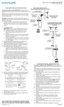
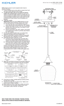
1) Loosen threaded stud on strain relief on canopy. Insert cord
into hole in strain relief and up into canopy.
2) To adjust the length of the cord to achieve the desired
height of the mounted fixture: Carefully pull cord up into
canopy to shorten the height of fixture or carefully pull cord
down to lengthen the height of fixture. When desired height
is achieved, tighten threaded stud on strain relief.
3) TURN OFF POWER.
IMPORTANT: Before you start, NEVER attempt any work
without shutting off the electricity until the work is done.
a) Go to the main fuse, or circuit breaker, box in your
home. Place the main power switch in the “OFF”
position.
b) Unscrew the fuse(s), or switch “OFF” the circuit breaker
switch(s), that control the power to the fixture or room
that you are working on.
c) Place the wall switch in the “OFF” position. If the fixture
to be replaced has a switch or pull chain, place those in
the “OFF” position.
4) With wire strippers, remove 2 inches from end of wire jacket
from cord. Then strip 1/2 inch from end of each colored wire
from wire jacket. REF: Stripped wires detail.
5) Find the appropriate threaded holes on mounting strap.
Assemble mounting screws into threaded holes.
6) Attach mounting strap to outlet box. Mounting strap can be
adjusted to suit position of fixture.
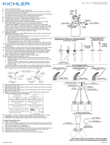
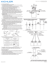
7) Grounding instructions: (See Illus. A or B).
A) On fixtures where mounting strap is provided with a
hole and two raise dimples. Wrap ground wire from
outlet box around green ground screw, and thread into
hole.
B) On fixtures where a cupped washer is provided. Put
ground wire from outlet box under cupped washer and
green ground screw and thread screw into hole in
mounting strap.
If fixture is provided with ground wire. Connect fixture
ground wire to outlet box ground wire with wire connector,
(not provided) after following the above steps. Never
connect ground wire to black or white power supply wires.
8) Make wire connections (connectors not provided.) Reference
chart below for correct connections and wire accordingly.
9) Push fixture to ceiling, carefully passing mounting screws
through holes in canopy and pushing wires into outlet box
without pinching wires.
10) Thread knurl knobs onto mounting screws. Tighten knurl
knobs to secure fixture to ceiling.
Date Issued: 9/25/15
IS-43719-US
GREEN GROUND
SCREW
CUPPED
WASHER
A
B
OUTLET BOX
GROUND
FIXTURE
GROUND
DIMPLES
WIRE CONNECTOR
(NOT PROVIDED)
OUTLET BOX
GROUND
GREEN GROUND
SCREW
FIXTURE
GROUND
Connect Black or
Red Supply Wire to:
Connect
White Supply Wire to:
Black White
*Parallel cord (round & smooth) *Parallel cord (square & ridged)
Clear, Brown, Gold or Black
without tracer
Clear, Brown, Gold or Black
with tracer
Insulated wire (other than green)
with copper conductor
Insulated wire (other than green)
with silver conductor
*Note: When parallel wires (SPT I & SPT II)
are used. The neutral wire is square shaped
or ridged and the other wire will be round in
shape or smooth (see illus.)
Neutral Wire
MOUNTING STRAP
ABRAZADERA DE MONTAJE
CANOPY
ESCUDETE
KNURL KNOB
PERILLA ESTRADA
CORD
CORDÓN
We’re here to help 866-558-5706
Hrs: M-F 9am to 5pm EST
SEE OTHER SIDE FOR SPANISH TRANSLATIONS.
VEA EL OTRO LADO DE TRADUCCIONES AL ESPAÑOL.
STRIPPED WIRES DETAIL
DETALLE DE LOS ALAMBRES PELADOS
WIRE JACKET
CAMISA DE ALAMBRE
COLORED WIRES
ALAMBRE DE
COLOR
CORD
CORDÓN
CANOPY
ESCUDETE

NOTA: La altura del artefacto debe ser ajustada antes de que el
artefacto sea montado en el techo.
1) Afloje el espárrago roscado en el alivio de la tensión en el
escudete. Inserte el cordón en el agujero en el alivio de
tensión y hasta en el escudete.
2) Para ajustar la longitud del cordón para lograr la altura
deseada del artefacto montado: Afloje el espárrago
roscado sobre el alivio de la tensión en el escudete. Jale el
cordón cuidadosamente hacia arriba dentro del escudete
para acortar la altura del artefacto o jale el cordón
cuidadosamente hacia abajo para alargar la altura del
artefacto. Cuando se alcance la altura deseada, apriete el
espárrago roscado.
3) APAGUE LA ALIMENTACIÓN ELÉCTRICA.
IMPORTANTE: Antes de comenzar, NUNCA trate de trabajar
sin antes desconectar la corriente hasta que el trabajo se
termine.
a) Vaya a la caja principal de fusibles, o interruptor o caja
de circuitos de su casa. Coloque el interruptor de la
corriente principal en posición de apagado “OFF”.
b) Desatornille el (los) fusible (s), o coloque el interruptor o
interruptores del breaker en posición de apagado
“OFF”, que controla (n) la corriente hacia el artefacto o
habitación donde está trabajando.
c) Coloque el interruptor de pared en posición de apagado
“OFF”. Si el artefacto que se va a reemplazar tiene un
interruptor o cadena que se jala, colóquelos en la
posición de apagado “OFF”.
4) Con un pelador de alambre, remueva 2 pulgadas desde el
extremo de cada camisa de alambre. Posteriormente pele ½
pulgada desde el extremo de cada alambre de color de la
camisa del alambre. REF: Detalle de los alambres pelados.
5) Encontrar los agujeros roscados correctos en la abrazadera
de montaje. Instalar los tornillos de montaje en los agujeros
roscados.
6) Unir la abrazadera de montaje a la caja de conexiones. La
abrazadera de montaje puede ajustarse para acomodar la
posición del artefacto.
7) Instrucciones de conexión a tierra solamente para los
Estados Unidos. (Vea la ilustracion A o B).
A) En las lámparas que tienen el fleje, de montaje con un
agujero y dos hoyue los realzados. Enrollar el alambre a
tierra de la caja tomacorriente alrededor del tornillo
verde y pasarlo por el aquiero.
B) En las lámparas con una arandela acopada. Fijar el
alambre a tierra de la caja tomacorriente del ajo de la
arandela acoada y tornillo verde, y paser por el fleje de
montaje.
Si la lámpara viene con alambre a tierra. Conecter el
alambre a tierra de la lámpara al alambre a tierra de la
caja tomacorriente con un conector de alambres (no incluido)
espués de seguir los pasos anteriores. Nunca conectar el
alambra a tierra a los alambres eléctros negro o blanco.
8) Haga les conexiones de los alambres (no se proveen los
connectores.) La tabla de referencia de abajo indica las
conexiones correctas y los alambres correspondientes.
Date Issued: 9/25/15 IS-43719-US
ARANDELA
CONCAVA
A
B
TIERRA DE LA
CAJA DE SALIDA
TORNILLO DE TIERRA,
VERDE
DEPRESIONES
TIERRA
ARTEFACTO
CONECTOR DE ALAMBRE
(NO SE PROVEE)
TIERRA DE LA
CAJA DE SALIDA
TORNILLO DE TIERRA,
VERDE
TIERRA
ARTEFACTO
9) Empuje el artefacto hacia el techo, pasando cuidadosamente
los tornillos de montaje a través de los orificios en el
escudete y empujar los alambres en la caja de salida y sin
pellizcar los alambres.
10) Atornille las perillas estriadas en los tornillos de montaje.
Ajuste las perillas estriadas para fijar el artefacto en el
techo.
Conectar el alambre de
suministro negro o rojo al
Conectar el alambre de
suministro blanco al
Negro Blanco
*Cordon paralelo (redondo y liso)
*Cordon paralelo (cuadrado y estriado)
Claro, marrón, amarillio o negro
sin hebra identificadora
Claro, marrón, amarillio o negro
con hebra identificadora
Alambre aislado (diferente del verde)
con conductor de cobre
Alambre aislado (diferente del
verde) con conductor de plata
*Nota: Cuando se utiliza alambre paralelo
(SPT I y SPT II). El alambre neutro es de forma
cuadrada o estriada y el otro alambre será de
forma redonda o lisa. (Vea la ilustracíón).
Hilo Neutral
We’re here to help 866-558-5706
Hrs: M-F 9am to 5pm EST
SEE OTHER SIDE FOR ENGLISH TRANSLATIONS.
VEA EL OTRO LADO DE TRADUCCIONES AL INGLÉS.
MOUNTING STRAP
ABRAZADERA DE MONTAJE
CANOPY
ESCUDETE
KNURL KNOB
PERILLA ESTRADA
CORD
CORDÓN
STRIPPED WIRES DETAIL
DETALLE DE LOS ALAMBRES PELADOS
WIRE JACKET
CAMISA DE ALAMBRE
COLORED WIRES
ALAMBRE DE
COLOR
CORD
CORDÓN
CANOPY
ESCUDETE
-
 1
1
-
 2
2


Kichler Lighting 43719RS Manual de usuario
- Tipo
- Manual de usuario
en otros idiomas
- English: Kichler Lighting 43719RS User manual
Artículos relacionados
-
 Kichler Lighting 43551NBR Manual de usuario
-
Kichler Lighting 43127NBR Manual de usuario
-
 Kichler Lighting 42877NI Manual de usuario
-
 Kichler Lighting 42869OZ Manual de usuario
-
 Kichler Lighting 43589NBR Manual de usuario
-
 Kichler Lighting 42890OZ Manual de usuario
-
 Kichler Lighting 43489BKSLV Manual de usuario
-
 Kichler Lighting 43624NI Manual de usuario


