GE AEG14AZ El manual del propietario
- Tipo
- El manual del propietario

Write the model and serial
numbers here:
Model # _________________
Serial # _________________
You can find the rating label on the
side of the air conditioner.
GE is a trademark of the General Electric Company. Manufactured under trademark license.
AIR CONDITIONER
ROOM
49-5000434 Rev. 2 01-20 GEA
AEG14
AEG18
AEG24
SAFETY INFORMATION .........3
USING THE AIR CONDITIONER
Controls ..............................4
CARE AND CLEANING
Air Filter ..............................7
Outdoor Coils .........................7
INSTALLATION
INSTRUCTIONS ....................8
TROUBLESHOOTING TIPS ......16
Normal Operating Sounds .............16
WIFI SETUP ......................17
LIMITED WARRANTY ............. 19
CONSUMER SUPPORT ...........20
OWNER’S MANUAL
AND INSTALLATION
INSTRUCTIONS

2 49-5000434 Rev. 2
THANK YOU FOR MAKING GE APPLIANCES A PART OF YOUR HOME.
Whether you grew up with GE Appliances, or this is your first, we’re happy to have you in the family.
We take pride in the craftsmanship, innovation and design that goes into every GE Appliances
product, and we think you will too. Among other things, registration of your appliance ensures that we
can deliver important product information and warranty details when you need them.
Register your GE appliance now online. Helpful websites and phone numbers are available in the
Consumer Support section of this Owner’s Manual. You may also mail in the pre-printed registration
card included in the packing material.

49-5000434 Rev. 2 3
READ AND SAVE THESE INSTRUCTIONS
IMPORTANT SAFETY INFORMATION
READ ALL INSTRUCTIONS BEFORE USING THE APPLIANCE
SAFETY INFORMATION
WARNING
For your safety, the information in this manual must be followed to minimize the risk of
fire, electric shock or personal injury.
Ŷ8VHWKLVDSSOLDQFHRQO\IRULWVLQWHQGHGSXUSRVHDV
described in this Owner’s Manual.
ŶThis air conditioner must be properly installed in
accordance with the Installation Instructions before it is
used.
ŶNever unplug your air conditioner by pulling on the
power cord. Always grip plug firmly and pull straight
out from the receptacle.
ŶReplace immediately all electric service cords that
have become frayed or otherwise damaged. A
damaged power supply cord must be replaced with a
new power supply cord obtained from the manufacturer
and not repaired. Do not use a cord that shows cracks
or abrasion damage along its length or at either the
plug or connector end.
ŶTurn the unit OFF and unplug your air conditioner
before cleaning.
ŶGE Appliances does not support any servicing of the
air conditioner. We strongly recommend that you do
not attempt to service the air conditioner yourself.
ŶFor your safety…do not store or use combustible
materials, gasoline or other flammable vapors or
liquids in the vicinity of this or any other appliance.
ŶAll air conditioners contain refrigerants, which under
federal law must be removed prior to product disposal.
If you are getting rid of an old product with refrigerants,
check with the company handling disposal about what
to do.
ŶIf the receptacle does not match the plug, the
receptacle must be changed out by a qualified
electrician.
ŶThese R410A air conditioning systems require
contractors and technicians to use tools, equipment
and safety standards approved for use with this
refrigerant. DO NOT use equipment certified for R22
refrigerant only.
WARNING
USE OF EXTENSION CORDS
RISK OF FIRE. Could cause serious injury or death.
Ŷ'2127XVHDQH[WHQVLRQFRUGZLWKWKLV:LQGRZ$LU
Conditioner.
Ŷ'2127XVHVXUJHSURWHFWRUVRUPXOWLRXWOHWDGDSWRUV
with this Window Air Conditioner.
HOW TO CONNECT ELECTRICITY
Do not, under any circumstances, cut or remove the third
(ground) prong from the power cord. For personal safety,
this appliance must be properly grounded.
DO NOT use an adapter plug with this appliance.
The power cord of this appliance is equipped with a
3-prong (grounding) plug which mates with a standard
3-prong (grounding) wall outlet to minimize the possibility
of electric shock hazard from this appliance.
Power cord includes a current interrupter device. A
test and reset button is provided on the plug case. The
device should be tested on a periodic basis by first
pressing the TEST button and then the RESET button
while plugged into the outlet. If the TEST button does
not trip or if the RESET button will not stay engaged,
discontinue use of the air conditioner and contact a
qualified service technician.
Have the wall outlet and circuit checked by a qualified
electrician to make sure the outlet is properly grounded.
Where a 2-prong wall outlet is encountered, it is your
personal responsibility and obligation to have it replaced
with a properly grounded 3-prong wall outlet.
The air conditioner should always be plugged into its
own individual electrical outlet which has a voltage rating
that matches the rating plate.
This provides the best performance and also prevents
overloading house wiring circuits which could cause a
fire hazard from overheated wires.
See the Installation Instructions, Electrical
Requirements section for specific electrical connection
requirements.
For appliance recycling information please visit geappliances.com/recycling.

4 49-5000434 Rev. 2
USING THE AIR CONDITIONER
Controls
Features and appearance will vary.
/LJKWVQH[WWRWKHWRXFKSDGVRQWKHDLUFRQGLWLRQHUFRQWUROSDQHOLQGLFDWHWKHVHOHFWHGVHWWLQJV
Air Conditioner Controls
NOTE: 7KHGLVSOD\DOZD\VVKRZVWKHURRPWHPSHUDWXUHH[FHSWZKHQ
setting the Set temperature or the Delay timer.
Remote Control
NOTE: The default temperature reading on the display is degree Fahrenheit ( °F). To change the display to degree
Celcius (°C), press the Temp Increase + and Temp Decrease – buttons together and hold for 3 seconds. Repeat the
process to change back to degree Fahrenheit (°F)
Auto
High
Med
Low
Cool
Fan
Eco
WiFiSleepFan Mode
Power
Temp
Do Not Operate in Freezing Outdoor Conditions
This cool-only air conditioner was not designed for freezing outdoor conditions. It must not be used in freezing
outdoor conditions.
Power Pad
Turns air conditioner on and off. When turned on,
the display will show the room temperature.
Display
Shows the room temperature or time remaining on
the Delay timer. Shows the Set temperature while
setting the temperature in Cool or ECO modes.
The Set light will turn on while setting.
Temp Increase + /Decrease – Pads
8VHWRVHWWHPSHUDWXUHZKHQLQCool or ECO
mode. The Set light will turn on while setting.
Fan Speed Pads
8VHWRVHWWKHIDQVSHHGWRLow, Med, High or
Auto on the unit. NOTE: On the remote control,
use the fan speed Increase + / Decrease – pads
to set the fan speeds to Low, Med or High8VH
the Auto pad to turn Auto fan on.
Mode Pad
8VHWRVHWWKHDLUFRQGLWLRQHUWR&RRO(&2RU)DQ
Only mode.
WiFI
Enables connection of the air conditioner to
the home WiFi. Download App for details at
GEAppliances.com/connect6HH:LIL6HW8SRQ
page 17.

49-5000434 Rev. 2 5
Using the Air Conditioner
USING THE AIR CONDITIONER
Remote Control
Ŷ7RHQVXUHSURSHURSHUDWLRQDLPWKHUHPRWHFRQWURODW
the signal receiver on the air conditioner.
Ŷ0DNHVXUHQRWKLQJLVEHWZHHQWKHDLUFRQGLWLRQHUDQG
the remote control that could block the signal.
Ŷ7KHUHPRWHFRQWUROVLJQDOKDVDUDQJHRIXSWR
20 feet.
Ŷ0DNHVXUHEDWWHULHVDUHIUHVKDQGLQVWDOOHGFRUUHFWO\
as indicated on the remote control.
Ŷ5HPRWHFRQWDLQVDPDJQHWDOORZLQJLWWRDWWDFKWR
metal surfaces.
Cool Mode
8VHWKH&RROPRGHDW/RZ0HG+LJKRU$XWR)DQ
6SHHGIRUFRROLQJ8VHWKH7HPSHUDWXUH,QFUHDVH
Decrease – pads to set the desired temperature between
64°F and 86°F in 1°F increments.
An electronic thermostat is used to maintain the room
temperature. The compressor will cycle on and off
to keep the room at the set level of comfort. Set the
thermostat at a lower number and the indoor air will
become cooler. Set the thermostat at a higher number
and the indoor air will become warmer.
NOTE: If the air conditioner is off and is then turned on
while set to a Cool setting or if turned from a fan setting
WRD&RROVHWWLQJLWPD\WDNHDSSUR[LPDWHO\PLQXWHVIRU
the compressor to start and cooling to begin.
Cooling Descriptions
For Normal Cooling—Select the Cool mode and High
or Med fan with a middle set temperature.
For Maximum Cooling—Select the Cool mode and
High fan with a lower set temperature.
For Quieter and Nighttime Cooling—Select the Cool
mode and Low fan with a middle set temperature.
Sleep Pad
The SLEEP mode sets the unit to gradually change
settings over an 8 hour period to allow for some
increased energy efficiency during sleep hours.
The SLEEP mode is available only in COOL and
FAN only settings.
Press the SLEEP mode pad and its light will
illuminate. The fan indicator will stay at the same
setting but the air conditioner will automatically
change the FAN speed to low in either COOL or
FAN only mode.
In FAN only mode, the fan will stay in the LOW
speed setting for 8 hours. After 8 hours, the air
conditioner will resume the settings that were in
place before the SLEEP mode pad was pressed.
In COOL mode, the fan will stay in the LOW speed
setting for 8 hours from the time the SLEEP mode
pad was pressed. The air conditioner will also
raise the set point 2°F in 30 minutes and 2°F more
in another 30 minutes where it will remain for the
QH[WKRXUV$IWHUKRXUVWKHDLUFRQGLWLRQHUZLOO
resume the settings that were in place before the
SLEEP mode pad was pressed.
While the unit is in SLEEP mode, pressing any pad
will return it to the settings that were in place before
the SLEEP mode pad was pressed.
Control Display On and Off
To reduce brightness during sleeping hours, this
air conditioner control display has an automatic
off feature where the control display will turn off
completely after 5 minute of inactivity. To illuminate
the control interface, press any button on the
control display or remote control. The control
display will illuminate all previously illuminated
LED’s. The control interface will now respond to
any prescribed button press after it is illuminated.
Press and hold the FAN+MODE buttons
simultaneously to toggle this feature ON or OFF.
The LED’s will now stay ON anytime the unit is
ON.
Control Sound On and Off
This air conditioner will make a beep when
the buttons on the control are pushed or if the
unit receives a command from the mobile app
or remote control. To silence these beeps,
simultaneously press the FAN and “-” buttons for 3
seconds. Press these buttons again to toggle the
sound back on.

6 49-5000434 Rev. 2
USING THE AIR CONDITIONER
Using the Air Conditioner
ECO Mode
This mode optimizes the cooling power of your air
conditioner, thereby saving you energy. Once the set
point temperature has been reached, the fan will cycle
off to save energy. The fan will cycle back on periodically
to insure all cooling capacity in the system is used. This
mode is the default mode for the unit. Each time the
unit is powered off, it will restart in ECO mode ON. This
includes Delay timer mode. The first time the unit is
turned on, the settings will be 70° and Low fan. You can
adjust the fan speed and temperature to your personal
comfort.
ECO ON—Helps minimize electricity use. It is normal
for the fan to cycle off and then back on in this mode.
7KLVRQRIIF\FOHFDQUHSHDWPXOWLSOHWLPHV%HFDXVH
the fan will cycle off, you may notice a variation in room
temperature and humidity.
ECO OFF—When this mode is not engaged, the fan will
run continuously, and in Cool mode the compressor will
cycle on and off to maintain room temperature.
Fan Only Mode
8VHWKH)DQ2QO\0RGHDW/RZ0HGRU+LJKIDQVSHHG
to provide air circulation and filtering without cooling.
Since fan-only settings do not provide cooling, a Set
temperature cannot be entered. The room temperature
will appear in the display.
NOTE: Auto Fan Speed cannot be used when in the Fan
Only Mode.
Auto Fan Speed
Set to Auto fan speed for the fan speed to automatically
set to the speed needed to provide optimum comfort
settings with the set temperature.
If the room needs more cooling, the fan speed will
automatically increase. If the room needs less cooling,
the fan speed will automatically decrease.
NOTE: Auto Fan Speed cannot be used when in the Fan
Only Mode.
Power Outage Recovery Feature
In the case of a power outage or interruption, the unit will
automatically restart in the settings last used after the
power is restored.
Air Direction
8VHWKHOHYHUWRDGMXVWWKHDLUGLUHFWLRQOHIWDQGULJKW
only.

49-5000434 Rev. 2 7
Care and Cleaning
Grille and Case
Turn the air conditioner off and remove the plug from the
wall outlet before cleaning.
To clean, use water and a mild detergent. Do not use
bleach or abrasives.
Air Filter
The air filter behind the front grille should be checked and
cleaned at least every 30 days or more often if necessary.
To remove:
Open the inlet grille by pulling downward on the tabs at
the top upper corners of the inlet grille until the grille is in
a 45º position. Remove the filter.
Clean the filter with warm, soapy water. Rinse and let the
filter dry before replacing it. Your filter is also dishwasher
safe, top rack and straight placement in dishwasher is
recommended.
CAUTION
DO NOT operate the air conditioner
without a filter because dirt and lint will clog it and reduce
performance.
Outdoor Coils
The coils on the outdoor side of the air conditioner should
be checked regularly. If they are clogged with dirt or soot,
they may be professionally cleaned.
How to Insert the Battery in the Remote Control
1.
Remove the battery cover by sliding it according to the
arrow direction.
2.
Insert new batteries, making sure that the (+) and (–)
of battery are installed correctly.
3.
Reattach the cover by sliding it back
into position.
NOTES:
Ŷ8VH³$$$´YROWEDWWHULHV'RQRWXVH
rechargeable batteries.
Ŷ Remove the batteries from the remote control if the
system is not going to be used for a long time.
Ŷ'RQRWPL[ROGDQGQHZEDWWHULHV'RQRWPL[DONDOLQH
standard (carbon-zinc) or rechargeable (ni-cad, ni-mh,
etc) batteries.
CARE AND CLEANING
Tab
Tab

8 49-5000434 Rev. 2
BEFORE YOU BEGIN
Read these instructions completely and
carefully.
•
IMPORTANT – Save these
instructions for local inspector’s use.
•
IMPORTANT – Observe all
governing codes and ordinances.
• Note to Installer ±%HVXUHWROHDYHWKHVH
instructions with the Consumer.
• Note to Consumer – Keep these instructions for
future reference.
• Skill level – Installation of this appliance requires
basic mechanical skills.
• Completion time ±$SSUR[LPDWHO\KRXU
• We recommend that two people install
this product.
• Proper installation is the responsibility
of the installer.
• Product failure due to improper installation is not
covered under the Warranty.
<RX0867XVHDOOVXSSOLHGSDUWVDQGXVHSURSHU
installation procedures as described in these
instructions when installing this air conditioner.
Questions? Call 1-800-GE-CARES or Visit our Website at: GEAppliances.com
ELECTRICAL
REQUIREMENTS
6RPHPRGHOVUHTXLUHDYROW$&
60-Hz grounded outlet protected with a
15-amp time-delay fuse or circuit breaker.
The 3-prong grounding plug minimizes the possibility
of electric shock hazard. If the wall outlet you plan to
use is only a 2-prong outlet, it is your responsibility to
have it replaced with a properly grounded 3-prong wall
outlet.
6RPHPRGHOVUHTXLUHYROW$&
protected with a time-delay fuse or circuit
breaker. These models should be installed on
their own single branch circuit for best
performance and to prevent overloading
house or apartment wiring circuits, which
could cause a possible fire hazard from
overheating wires.
CAUTION
Do not, under any circumstances, cut or remove the
third (ground) prong from the power cord.
Do not change the plug on the power cord of this air
conditioner.
Aluminum house wiring may present special
problems—consult a qualified electrician.
Installation Instructions
INSTALLATION INSTRUCTIONS
TOOLS YOU WILL NEED
Phillips head screwdriver
Ruler or tape measurePencil
Level
Scissors or knife
Flat-blade screwdriver
Power cord includes a current interrupter device. A
test and reset button is provided on the plug case.
The device should be tested on a periodic basis
by first pressing the TEST button and then the
RESET button while plugged into the outlet. If the
TEST button does not trip or if the RESET button
will not stay engaged, discontinue use of the
air conditioner and contact a qualified service
technician.

49-5000434 Rev. 2 9
Installation Instructions
INSTALLATION INSTRUCTIONS
Window
locking
bracket (2)
Top
mounting
rail
Sill angle
bracket (2)
Foam top window
gasket (1)
Side rail (2)
PARTS INCLUDED
(Appearance may vary)
Top rail gasket (1)
Type E bolt with
nut (4)
Type A
screws (10)
7\SH%
screws (2)
Type C
screws (4)
Type C
screws (5)
Type F bolt with
nut (2)
V-supports (2)
Window
sash seal
Left accordion
panel
Right accordion
panel
For Model: AEG24
For Models: AEG14, AEG18

10 49-5000434 Rev. 2
Installation Instructions
INSTALLATION INSTRUCTIONS
2. STORM WINDOW REQUIREMENTS
A storm window frame will not allow the air
conditioner to tilt toward the outside, and will
keep it from draining properly. To adjust for this,
attach a piece of wood to the sill.
WOOD PIECES
WIDTH: 2Ǝ
LENGTH: Long enough to fit inside the window
frame.
THICKNESS: To determine the thickness, place
DSLHFHRIZRRGRQWKHVLOOWRPDNHLWƎKLJKHU
than the top of the storm window frame or the
vinyl frame.
Attach securely with nails or screws provided by
the installer.
ƎKLJKHU
than storm
window
frame
Storm window
frame
Wood
Sill
ƎKLJKHU
than vinyl frame
(on some windows)
Vinyl frame
3. PREPARE THE AIR
CONDITIONER
A. Pull down the front panel and remove the filter.
Remove the front panel by lifting up at an angle.
B. Remove the four front screws. Save them for
reinstalling the front housing.
C. Grasp the lower corners of the grille while
pressing in on the case sides with your finger
tips. Pull out to release and lift it up.
NOTE: Do not pull the bottom edge toward you
PRUHWKDQƎRU\RXPD\GDPDJHWKHWDEVRIWKH
grille.
D. When the front grille is removed the control
panel will still be attached by a harness. Turn
the grille around so you can see the back side
of the grille. Remove the 2 screws to separate
the control panel housing from the grille. NOTE:
%HVXUHWRVDYHWKHVHVFUHZV<RXZLOOQHHG
them later in the installation.
Remove Screws
1. WINDOW REQUIREMENTS
• These instructions are for a standard
double-hung window. You will need to modify
them for other types of windows.
• The air conditioner can be installed without the
accordion panels if needed to fit in a narrow
window. See the window opening dimensions.
• All supporting parts must be secured to firm
wood, masonry or metal.
• The electrical outlet must be within reach of the
power cord.
A
(With accordion panels)
%
Model A B
AEG14, AEG18 ´PLQ 26”- 41”
AEG24 ´PLQ 30”- 41”

49-5000434 Rev. 2 11
4. PREPARE THE CASE
A.
Attach the top rail gasket to
the bottom of the top rail.
B. Install the top mounting rail with 4 type A screws
from the inside of the case. Press firmly to drive
the screws into the gasket and through the top
mounting rail.
Installation Instructions
INSTALLATION INSTRUCTIONS
3. PREPARE THE AIR
CONDITIONER (continues)
E. Remove the ground screw from the left side of
the case. Keep it in a safe location.
NOTE: %HVXUHWRVDYHWKLVVFUHZ<RXZLOO
need them later in the installation.
F. Slide the air conditioner from the case by
gripping the base pan handle and pulling
forward while bracing the case. Do not pull or lift
on the foam discharge area.
FRONT
Do not pull
or lift in
this area—
damage to
the unit may
result
4. PREPARE THE CASE
C. Slide each side retainer onto the edge of each
according panel. The figure shows the orientation
of each accordion panel and side retainer
assembly relative to the case from a top view of
the unit.
D. Slide the left and right accordion panels into the
top and bottom mounting rails.
E. Attach the side retainers to the case using 6 type A
screws.
WINDOW FILLER PANEL
WINDOW FILLER PANEL
SIDE RETAINER
SIDE RETAINER
Top mounting rail
Top left
Top right
Top mounting rail
%RWWRPPRXQWLQJUDLO

12 49-5000434 Rev. 2
Installation Instructions
INSTALLATION INSTRUCTIONS
5.
PREPARE THE WINDOW AND
INSTALL THE CASE
A. Cut the window sash seal to the proper length.
Peel off the backing and attach the seal to the
underside of the window sash.
B. Open the window and mark the center of the
window sill.
C. Carefully slide the case into the window and
center the case. Lower the window behind the
top mounting rail. Pull the bottom of the case
forward so that the bottom mounting rail is tight
against the back of the window stool. Mount the
FDVHWRWKHZLQGRZVLOOXVLQJW\SH%VFUHZV
Drill pilot holes, if necessary.
D. Assemble the V-support and V-support bracket
with Type F nut and bolt
5. PREPARE THE WINDOW AND
INSTALL THE CASE (continues)
E. Position the V-supports on
the case bottom so that they
will be near the outside wall.
Attach a V-support to each
side of the bottom of the
case with Type E bolts, 2 for
each support.
F. Adjust sill angle brackets to rest on sill.
G. ([WHQGWKHOHIWDQGULJKWDFFRUGLRQSDQHOVWRWKH
vertical window sashes. Drill pilot holes and attach
the top corners with 2 type C screws.
W\SH%VFUHZV
Stool
V-support
Sill
%UDFNHW
Type C
screw
Type C
screw
Sill angle
bracket
V-support
Type F bolt
and nut
Right
and nut
Type E bolt

49-5000434 Rev. 2 13
Installation Instructions
INSTALLATION INSTRUCTIONS
5. PREPARE THE WINDOW AND
INSTALL THE CASE (continues)
8VH7\SH%6FUHZWRLQVWDOOWKHZLQGRZORFN
bracket on top of the bottom window.
H.
CAUTION
To prevent broken glass or
damage to windows, on vinyl
or other similarly constructed
windows, attach the window
locking bracket to the
window side jamb with one
7\SH%VFUHZ
I. Cut the foam top window gasket to the
window width.
J. Stuff the foam between the glass and the
window to prevent air and insects from getting
into the room.
NOTE: If the gasket supplied does not fit your
window, obtain appropriate material locally to
provide a proper installation seal.
Wood
Vinyl
6.
INSTALL THE AIR CONDITIONER
IN THE CASE
A. Slide the air conditioner into the case by
the base pan. Do not push on the controls, foam
air discharge housing or the finned coils. Make
sure the air conditioner is firmly seated.
Do not press on
these areas—
damage to the unit
may result
%DVH3DQ

14 49-5000434 Rev. 2
Installation Instructions
INSTALLATION INSTRUCTIONS
6.
INSTALL THE AIR CONDITIONER
IN THE CASE (continues)
B. Replace the 1 screw removed earlier, one
on each side of the case.
,03257$177+(*5281'6&5(:60867
%(5(,167$//('72(1685(3523(5
*5281'
C. Reinstall the control to the panel housing by
replacing the 2 screws you removed earlier.
D. Attach the front grille to the case by inserting
the tabs on the grille into the slots on the front
top of the case. Push the grille in.
E. Replace the screws.
F. Install the filter and the front grille.
G. Plug in the air conditioner.
Install Screws

49-5000434 Rev. 2 15
The case may be installed through-the-wall in
both existing and new construction.
Read completely, then follow step-by-step.
NOTE: Obtain all materials locally for mounting
the air conditioner through-the-wall.
1. IMPORTANT
Through-the-wall installation is not
appropriate if any of the side or top louvers
in the case will be obstructed by the wall.
All side and top louvers in the case must
project on the outdoor side of the wall.
The room side of the case must project into
the room far enough to maximize the balance
of the unit.
The case must be installed level from side-
to-side and with a slight tilt from front to
rear. Use a level; no more than a 1/2 bubble
will be the correct case slant to the outside.
Lintel angle is required to support bricks or
blocks above opening.
Flashing is required and should extend the
length of the opening to ensure no inside
cavity leakage occurs.
A. Remove the air conditioner from the case.
For specific instruction, refer to the Window
Installation Instructions.
B. Make certain that a wall receptacle is available
close to the hole location or make arrangements
to install a receptacle.
C. Place the case in the wall opening and place
wood support strips between the case bottom
and the flashing on both sides of the bottom rail.
They should be the same height as the bottom
rail and the same length as the wall opening.
2.
FINISH THE WALL OPENING
A. Caulk all four sides on the outdoor side of the
case to prevent moisture from getting through
WRWKHLQWHULRUZDOO8VHRIIODVKLQJGULSUDLOZLOO
further prevent water from dripping inside the
wall and down the outside of the building.
B. Place the air conditioner into the case.
For specific instruction, refer to the Window
Installation Instructions.
1.
IMPORTANT (cont.)
D. Secure with 14 wood screws anchored at least
an inch into the wall support structure.
NOTE: Drill pilot holes, if necessary, for proper
installation. If the frame is oversized, use shims
to prevent case distortion.
Lintel angle
Plaster line
Trim molding
(if desired)
INSIDE
%RWWRPUDLO
Wood filler and
caulking (above
and below the
flashing)
Air louvers
(top and sides
must project
on the outdoor
side of the
wall)
2876,'(
Flashing
(Drip rail)
Case
bottom
%RWWRP
rail
Flashing
(Drip rail)
Wood support strips
Caulking
Through-the-Wall Installation Instructions—Optional
INSTALLATION INSTRUCTIONS

16 49-5000434 Rev. 2
Troubleshooting Tips... %HIRUH\RXFDOOIRUVHUYLFH
Save time and money! Review the charts on the following pages first and you may not need to call for service.
TROUBLESHOOTING TIPS
Problem Possible Causes What To Do
Air conditioner does
not start
The air conditioner is unplugged. Make sure the air conditioner plug is pushed completely into
the outlet.
The fuse is blown/circuit breaker
is tripped.
&KHFNWKHKRXVHIXVHFLUFXLWEUHDNHUER[DQGUHSODFHWKH
fuse or reset the breaker.
Power failure. The unit will automatically restart in the settings last used
after the power is restored.
7KHUHLVDSURWHFWLYHWLPHGHOD\DSSUR[LPDWHO\PLQXWHVWR
prevent tripping of the compressor overload. For this reason,
the unit may not start normal cooling for 3 minutes after it is
turned back on.
The current interrupter device is
tripped.
Press the RESET button located on the power cord plug.
If the RESET button will not stay engaged, discontinue
use of the air conditioner and contact a qualified service
technician.
Air conditioner does
not cool as it should
Airflow is restricted. Make sure there are no curtains, blinds or furniture blocking
the front of the air conditioner.
The temp control may not be set
correctly.
On models with touch pads: In the Cool mode, press the
Decrease – pad.
On models with control knobs, turn the temperature knob to
a higher number.
The air filter is dirty. Clean the filter at least every 30 days. See the Care and
Cleaning section.
The room may have been hot. When the air conditioner is first turned on, you need to allow
time for the room to cool down.
Cold air is escaping. Check for open furnace registers and cold air returns.
Cooling coils have iced up. See “Air conditioner freezing up” below.
Air conditioner freezing
up
Ice blocks the air flow and stops
the air conditioner from cooling
the room.
On models with control knobs, set the mode control at High
Fan or High Cool with the Temp at 1 or 2.
On models with touch pads, set the controls at High Fan or
High Cool and set the thermostat to a higher temperature.
The remote control is
not working
The batteries are inserted
incorrectly.
Check the position of the batteries. They should be inserted
in the opposite (+) and (–) direction.
The batteries may be dead. Replace the batteries.
Water drips outside Hot, humid weather. This is normal.
Water drips indoors The air conditioner is not tilted
to the outside.
For proper water disposal, make sure the air conditioner
slants slightly from the case front to the rear.
Water collects in base
pan
Moisture removed from air and
drains into base pan.
This is normal for a short period in areas with little humidity;
normal for a longer period in very humid areas.
Normal Operating Sounds
Ŷ You may hear a pinging noise caused by water being
picked up and thrown against the condenser on rainy
days or when the humidity is high. This design feature
helps remove moisture and improve efficiency.
Ŷ You may hear the thermostat click when the
compressor cycles on and off.
Ŷ Water will collect in the base pan during high humidity
or on rainy days. The water may overflow and drip
from the outdoor side of the unit.
Ŷ The fan may run even when the compressor does not.

49-5000434 Rev. 2 17
WiFi Setup
WIFI SETUP
GE Appliances WiFi Connect (for customers in the United States)
GE Appliances U+ Connect Enabled*
If your Air Conditioner (AC) has a Connected Appliance Information label
located on the outside as shown below, your AC is GE Appliances U+ Connect Enabled. A WiFi communication
card is built into the product allowing it to communicate with your smart phone for remote monitoring, control and
notifications. Please visit GEAppliances.com/connect to learn more about connected appliance features, and to
learn what connected appliance apps will work with your smart phone. For assistance,
call 1-800-220-6899.
Network: GE_MODULE_XXXXNetwork: GE_MODULE_XXXX
PASSWORD: XXXXXXXX
MAC ID: XX-XX-XX-XX-XX-XX
CONTAINS FCCID: ZKJ-WCATB002
CONTAINS IC:
100229A-WCATB002
123-45-678
How it Works
Download the GE Appliances App
8VHWKHDSSWRFRQQHFW\RXUURRPDLU
conditioner to WiFi
Once connected, use the app to turn
down your air conditioner as you
leave work.
CHANGE TEMP
TO 65
Getting Started
To connect your room air conditioner, you’ll need the
GE Appliances App. The app will walk you through the
connection process. Download the app from iTunes or
Google Play.
All connected appliace data is held in strict accordance
with the GE Appliances Connected Data Privacy Policy.
Visit geappliances.com/privacy/privacy_policy_
connected to view this policy.
Questions about U+ Connect
Get answers you need about setting up WiFi appliances
and connecting to your home network in our support
articles.
Visit products.geappliances.com/appliance/gea-
support-search-content to view wifi connect room air
conditioner support articles.

18 49-5000434 Rev. 2
WiFi Setup
WIFI SETUP
REGULATORY INFORMATION
FCC/IC Compliance Statement:
This device complies with Part 15 of the FCC Rules.
Operation is subject to the following two conditions:
1. This device may not cause harmful interference.
2. This device must accept any interference received,
including interference that may cause undesired
operation.
This equipment has been tested and found to comply
ZLWKWKHOLPLWVIRUD&ODVV%GLJLWDOGHYLFHSXUVXDQWWR
Part 15 of the FCC Rules. These limits are designed
to provide reasonable protection against harmful
interference in a residential installation. This equipment
generates uses and can radiate radio frequency energy
and, if not installed and used in accordance with the
instructions, may cause harmful interference to radio
communications. However, there is no guarantee that
interference will not occur in a particular installation. If
this equipment does cause harmful interference to radio
or television reception, which can be determined by
turning the equipment off and on, the user is encouraged
to try to correct the interference by one or more of the
following measures:
• Reorient or relocate the receiving antenna.
• Increase the separation between the equipment and
receiver.
• Connect the equipment into an outlet on a circuit
different from that to which the receiver is connected.
&RQVXOWWKHGHDOHURUDQH[SHULHQFHGUDGLRWHOHYLVLRQ
technician for help.
Labelling: Changes or modifications to this unit not
H[SUHVVO\DSSURYHGE\WKHPDQXIDFWXUHUFRXOGYRLGWKH
user’s authority to operate the equipment.
*Select Models Only
This product has Wi-Fi capability and requires
Internet connectivity and a wireless router to enable
interconnection with an Energy Management System,
DQGRUZLWKRWKHUH[WHUQDOGHYLFHVV\VWHPVRU
applications.
8VHRIWKH:RUNVZLWK$SSOH+RPH.LWORJRPHDQV
that an electronic accessory has been designed to
connect specifically to iPod touch
®
, iPhone
®
, or iPad
®
,
respectively, and has been certified by the developer
to meet Apple
®
performance standards. Apple is
not responsible for the operation of this device or its
compliance with safety and regulatory standards.

49-5000434 Rev. 2 19
LIMITED WARRANTY
GE Appliances Air Conditioner - One-Year Limited Warranty
Ŷ6HUYLFHWULSVWR\RXUKRPHWRWHDFK\RXKRZWRXVH
the product.
Ŷ,PSURSHULQVWDOODWLRQGHOLYHU\RUPDLQWHQDQFH,I\RX
have an installation problem, or if the air conditioner
is of improper cooling capacity for the intended use,
contact your dealer or installer. You are responsible
for providing adequate electrical connecting facilities.
Ŷ)DLOXUHRIWKHSURGXFWUHVXOWLQJIURPPRGLILFDWLRQV
to the product or due to unreasonable use including
failure to provide reasonable and necessary
maintenance.
Ŷ,QFRPPHUFLDOORFDWLRQVODERUQHFHVVDU\WRPRYHWKH
unit to a location where it is accessible for service by
an individual technician.
Ŷ5HSODFHPHQWRIKRXVHIXVHVRUUHVHWWLQJRIFLUFXLW
breakers.
Ŷ)DLOXUHGXHWRFRUURVLRQRQPRGHOVQRWFRUURVLRQ
protected.
Ŷ'DPDJHWRWKHSURGXFWFDXVHGE\LPSURSHUSRZHU
supply voltage, accident, fire, floods or acts of God.
Ŷ,QFLGHQWDORUFRQVHTXHQWLDOGDPDJHFDXVHGE\
possible defects with this air conditioner.
Ŷ'DPDJHFDXVHGDIWHUGHOLYHU\
What GE Appliances Will Not Cover:
7KLVOLPLWHGZDUUDQW\LVH[WHQGHGWRWKHRULJLQDOSXUFKDVHUDQGDQ\VXFFHHGLQJRZQHUIRUSURGXFWVSXUFKDVHG
IRUKRPHXVHZLWKLQWKH86$,IWKHSURGXFWLVORFDWHGLQDQDUHDZKHUHVHUYLFHE\D*($SSOLDQFHV$XWKRUL]HG
Servicer is not available, you may be responsible for a trip charge or you may be required to bring the product to an
$XWKRUL]HG*($SSOLDQFHV6HUYLFHORFDWLRQIRUVHUYLFH,Q$ODVNDWKHOLPLWHGZDUUDQW\H[FOXGHVWKHFRVWRIVKLSSLQJ
or service calls to your home.
6RPHVWDWHVGRQRWDOORZWKHH[FOXVLRQRUOLPLWDWLRQRILQFLGHQWDORUFRQVHTXHQWLDOGDPDJHV7KLVOLPLWHGZDUUDQW\
gives you specific legal rights, and you may also have other rights which vary from state to state. To know what your
legal rights are, consult your local or state consumer affairs office or your state’s Attorney General.
Warrantor: GE Appliances, a Haier company
Louisville, KY 40225
(;&/86,212),03/,(':$55$17,(6²<RXUVROHDQGH[FOXVLYHUHPHG\LVSURGXFWUHSDLUDVSURYLGHGLQWKLV
Limited Warranty. Any implied warranties, including the implied warranties of merchantability or fitness for a particular
purpose, are limited to one year or the shortest period allowed by law.
For The Period Of: GE Appliances Will Replace:
One Year
From the date of the
original purchase
Any part of the air conditioner which fails due to a defect in materials or workmanship. During
this limited one-year warranty, GE Appliances will also provide, free of charge, all labor
and related service to replace the defective part.
Staple your receipt here. Proof of the original purchase
date is needed to obtain service under the warranty.
All warranty service provided by our Factory Service Centers, or an authorized Customer Care® technician. To
schedule service, visit us on-line at geappliances.com, or call 1-800-GE-CARES Have serial number and model
number available when calling for service.

20 49-5000434 Rev. 2
Printed in China
Consumer Support
CONSUMER SUPPORT
GE Appliances Website
Have a question or need assistance with your appliance? Try the GE Appliances Website 24 hours a day, any day
of the year! You can also shop for more great GE Appliances products and take advantage of all our on-line support
VHUYLFHVGHVLJQHGIRU\RXUFRQYHQLHQFH,QWKH86GEAppliances.com
Register Your Appliance
Register your new appliance on-line at your convenience! Timely product registration will allow for enhanced
communication and prompt service under the terms of your warranty, should the need arise. You may also mail in
WKHSUHSULQWHGUHJLVWUDWLRQFDUGLQFOXGHGLQWKHSDFNLQJPDWHULDO,QWKH86GEAppliances.com/register
Parts and Accessories
Individuals qualified to service their own appliances can have parts or accessories sent directly to their homes
(VISA, MasterCard and Discover cards are accepted). Order on-line today 24 hours every day.
,QWKH86GEApplianceparts.com or by phone at 877.959.8688 during normal business hours.
Instructions contained in this manual cover procedures to be performed by any user. Other servicing
generally should be referred to qualified service personnel. Caution must be exercised, since improper
servicing may cause unsafe operation.
Contact Us
If you are not satisfied with the service you receive from GE Appliances, contact us on our Website with all the
details including your phone number, or write to:
,QWKH86*HQHUDO0DQDJHU&XVWRPHU5HODWLRQV_*($SSOLDQFHV$SSOLDQFH3DUN_/RXLVYLOOH.<
GEAppliances.com/contact

Escriba los números de modelo
y serie aquí:
# de Modelo _____________
# de Serie _______________
Puede encontrar estos números
en una etiqueta en el costado
del acondicionador de aire.
GE es una marca registrada de General Electric Company. Fabricado bajo licencia de marca.
MANUAL DEL
PROPIETARIO Y
INSTRUCCIONES
DE INSTALACIÓN
INSTRUCCIONES
DE SEGURIDAD
...................3
USO DEL ACONDICIONADOR
DE AIRE
Controle ..............................4
CUIDADO Y LIMPIEZA
Filtro de aire ..........................7
Bobinas para exteriores ................7
INSTRUCCIONES
DE INSTALACIÓN ................8
SOLUCIONAR PROBLEMAS ....16
Sonidos de operación normales ........16
CONFIGURACIÓN WIFI .........17
GARANTÍA LIMITADA ..........19
SERVICIO AL CONSUMIDOR .. 20
ACCONDICIONADORES DE AIRE
PARA SALA
49-5000434 Rev. 2 01-20 GEA
AEG14
AEG18
AEG24

2 49-5000434 Rev. 2
GRACIAS POR HACER QUE GE APPLIANCES SEA PARTE DE SU HOGAR.
Ya sea que haya crecido usando GE Appliances, o que ésta es su primera vez, nos complace
tenerlo en la familia.
Sentimos orgullo por el nivel de arte, innovación y diseño de cada uno de los electrodomésticos de
GE Appliances, y creemos que usted también. Entre otras cosas, el registro de su electrodoméstico
asegura que podamos entregarle información importante del producto y detalles de la garantía
cuando los necesite.
Registre su electrodoméstico GE ahora a través de Internet. Sitios Web y números telefónicos útiles
están disponibles en la sección de Soporte para el Consumidor de este Manual del Propietario.
También puede enviar una carta en la tarjeta de inscripción preimpresa que se incluye con
el material embalado.

49-5000434 Rev. 2 3
INFORMACIÓN DE SEGURIDAD
LEA Y GUARDE ESTAS INSTRUCCIONES
INFORMACIÓN IMPORTANTE DE SEGURIDAD
LEA TODAS LAS INSTRUCCIONES ANTES DE USAR
ADVERTENCIA
Para su seguridad, siga las instrucciones de este manual a fin de minimizar riesgos de
incendio, descargas eléctricas o heridas personales.
Ŷ8VHHVWHHOHFWURGRPpVWLFRVyORSDUDVXSURSyVLWRRULJLQDO
como se describe en el Manual del Propietario.
Ŷ(VWHDFRQGLFLRQDGRUGHDLUHVHGHEHLQVWDODUGHIRUPD
apropiada de acuerdo con las Instrucciones de Instalación
antes de ser usado.
Ŷ1XQFDGHVHQFKXIHVXDFRQGLFLRQDGRUGHDLUHHPSXMDQGR
el cable de corriente. Siempre tome su enchufe de manera
firme y empuje el mismo hacia afuera del receptáculo.
Ŷ5HHPSODFHGHLQPHGLDWRWRGRVORVFDEOHVGHOVHUYLFLR
GHHOHFWULFLGDGSHODGRVRFRQFXDOTXLHUWLSRGHGDxR8Q
cable del servicio de corriente que esté dañado deberá ser
reemplazado por uno nuevo provisto por el fabricante, y
QRGHEHUiVHUUHSDUDGR1RXVHXQFDEOHFRQFRUWDGXUDVR
abrasión sobre su extensión o en cualquiera de sus enchufes
o extremos.
Ŷ&RORTXHODXQLGDGHQ2))$SDJDGR\GHVHQFKXIHHO
acondicionador de aire antes de usar el mismo.
Ŷ*($SSOLDQFHVQRVXPLQLVWUDVHUYLFLRWpFQLFRSDUDHO
acondicionador de aire. Recomendamos enfáticamente que
no intente reparar el acondicionador de aire usted mismo.
Ŷ3DUDVXVHJXULGDGQRDFXPXOHQLXVHPDWHULDOHV
combustibles, gasolina u otros vapores o líquidos inflamables
cerca de éste u otro electrodoméstico.
Ŷ7RGRVORVDFRQGLFLRQDGRUHVGHDLUHFRQWLHQHQUHIULJHUDQWHV
los cuales de acuerdo con la ley federal se deben quitar
antes de deshacerse del producto. Si se deshará de un
producto antiguo con refrigerantes, consulte a la compañía a
cargo sobre cómo deshacerse del mismo.
Ŷ6LHOUHFHSWiFXORQRFRLQFLGHFRQHOHQFKXIHHOFDPELRGHO
mismo deberá ser realizado por un electricista calificado.
Ŷ(VWRVVLVWHPDVGHDFRQGLFLRQDGRUHVGHDLUH5$
requieren que los contratistas y técnicos utilicen
herramientas, equipamiento y estándares de seguridad
DSUREDGRVSDUDVXXVRFRQHVWHUHIULJHUDQWH12XVH
equipamiento certificado sólo para refrigerante R22.
ADVERTENCIA
USO DE PROLONGADORES
RIESGO DE INCENDIO. Podría ocasionar lesiones graves o
la muerte.
Ŷ12XVHXQSURORQJDGRUFRQHVWH$FRQGLFLRQDGRUGH$LUHGH
Ventana.
Ŷ12XVHSURWHFWRUHVFRQWUDSLFRVGHFRUULHQWHQLDGDSWDGRUHV
para múltiples tomacorrientes con este Acondicionador de
Aire de Ventana.
CÓMO CONECTAR LA ELECTRICIDAD
1XQFDEDMRQLQJXQDFLUFXQVWDQFLDFRUWHRHOLPLQHHOWHUFHU
FDEOHWLHUUDGHOFDEOHGHFRUULHQWH3DUDVXVHJXULGDG
personal, este electrodoméstico debe estar adecuadamente
conectado a tierra.
NO use un enchufe adaptador con este electrodoméstico.
El cable de corriente de este electrodoméstico contiene un
HQFKXIHGHFDEOHVFRQH[LyQDWLHUUDTXHVHFRQHFWDDXQ
WRPDFRUULHQWHGHSDUHGHVWiQGDUGHFDEOHVFRQH[LyQD
WLHUUDSDUDPLQLPL]DUODSRVLELOLGDGGHULHVJRVGHGHVFDUJDV
eléctricas por parte del mismo.
El cable de corriente incluye un interruptor de corriente.
Se brinda un botón de evaluación y reinicio en la caja
del enchufe. El dispositivo deberá ser evaluado en forma
periódica, presionando primero el botón TEST(YDOXDU\
luego RESET5HLQLFLRPLHQWUDVVHHQFXHQWUHHQFKXIDGRDO
tomacorriente. Si el botón TEST (YDOXDUQRVHDFWLYDRHO
botón RESET5HLQLFLRQRSHUPDQHFHHQVXSRVLFLyQGHMHGH
usar el acondicionador de aire y comuníquese con un técnico
calificado del servicio.
Contrate a un electricista calificado para que controle el
tomacorriente y el circuito eléctrico para asegurar que el
enchufe esté correctamente conectado a tierra.
En caso de contar con un tomacorriente de pared de 2 cables,
es su responsabilidad y obligación reemplazarlo por un
tomacorriente de pared de 3 cables correctamente conectado
a tierra.
El acondicionador de aire debería estar siempre conectado a
un enchufe específico con un índice de voltaje equivalente al
que figura en su etiqueta de características técnicas.
Esto garantiza el mejor funcionamiento y además previene la
sobrecarga de los circuitos del hogar, lo cual podría ocasionar
riesgos de incendio debido al recalentamiento de cables.
Para conocer los requisitos específicos de la conexión
eléctrica, consulte las Instrucciones de Instalación, Requisitos
Eléctricos.
Para acceder a información sobre como reciclar sus electrodomésticos, ingrese a geappliances.com/recycling.

49-5000434 Rev. 2
Controles
USO DEL ACONDICIONADOR DE AIRE
Las luces al lado de las teclas de toque en el panel de control del acondicionador de aire indicarán los ajustes seleccionados.
Las funciones y el aspecto pueden variar.
Controles del acondicionador de aire
NOTA:/DWHPSHUDWXUDSRUGHIHFWRTXHILJXUDHQODSDQWDOODHVWiHQJUDGRV)DKUHQKHLW)3DUDPRGLILFDUODSDQWDOODDJUDGRV
&HOVLXV&PDQWHQJDSUHVLRQDGRVORVERWRQHV7HPS,QFUHDVH,QFUHPHQWRGH7HPSHUDWXUD+7HPS'HFUHDVH'LVPLQXFLyQGH
7HPSHUDWXUD
–DOPLVPRWLHPSR\GXUDQWHVHJXQGRV5HSLWDHOSURFHVRSDUDYROYHUDPRGLILFDUODSDQWDOODDJUDGRV)DKUHQKHLW)
NOTA: La pantalla muestra siempre la temperatura ambiente, excepto
al configurar la temperatura Definida o el Sincronizador de retardo.
Control Remoto
No use en las condiciones externas debajo el punto de congelación
(VWHDFRQGLFLRQDGRUGHDLUHQRHVGLVHxDGRSDUDXVDUHQWHPSHUDWXUDVH[WHUQDVGHEDMRHOSXQWRGHFRQJHODFLyQ1RXVHHQODV
condiciones externas debajo el punto de congelación.
Auto
High
Med
Low
Cool
Fan
Eco
WiFiSleep
Fan Mode
Power
Temp
Tecla de Power (Encendido)
Apaga y prende el acondicionador de aire. Al encenderse,
la pantalla mostrará la temperatura ambiente.
Pantalla
Muestra la temperatura ambiente o el tiempo restante
en el Sincronizador de retardo. Muestra la temperatura
Definida al configurar la temperatura en los modos Cool
(Frío) o de ECO (Ahorro de energía). La luz de Ajuste
se encenderá durante la configuración.
Teclas de Temp Aumento + /Reducción –
8VDGRSDUDDMXVWDUODWHPSHUDWXUDFXDQGR
se encuentre en el modo Cool (Frío) o ECO (Ahorro
de energía). La luz de Ajuste se encenderá durante la
configuración.
Teclas de Fan Speed (Velocidad del ventilador)
8VDGRSDUDDMXVWDUODYHORFLGDGGHOYHQWLODGRUDLow
(Bajo), Med (Medio), High (Alto) o Auto (Automática)
en la unidad. NOTA: en el control remoto, utilice las
teclas Aumento + / Reducción – velocidad de ventilador
para ajustar la velocidad del ventilador en Low (Bajo),
Med (Medio) o High (Alto)8WLOLFHODWHFODAuto para
activar el ventilador automático.
Tecla de MODO
8VDGRSDUDDMXVWDUHODFRQGLFLRQDGRUGHDLUHDOPRGR
Cool (Frío), ECO (Ahorro de energía) o Fan Only (Solo
ventilador).
WiFi
WiFi Connect le permite la conexión del acondicionador
de aire al WiFi del hogar. Descargue los detalles de la
Aplicación en GEAppliances.com/connect. Consulte
&RQILJXUDFLyQGH:LILHQODSiJLQD

49-5000434 Rev. 2 5
USO DEL ACONDICIONADOR DE AIRE
Controles
Control Remoto
Ŷ3DUDJDUDQWL]DUXQDRSHUDFLyQDSURSLDGDRULHQWHHOFRQWURO
remoto hacia el receptor de señal del acondicionador de
aire.
Ŷ&HUFLyUHVHGHTXHQRKD\DQDGDHQWUHHODFRQGLFLRQDGRUGH
aire y el control remoto que pueda bloquear la señal.
Ŷ(OUHFHSWRUGHVHxDOWLHQHXQUDQJRPi[LPRGHSLHV
Ŷ&HUFLyUHVHGHTXHODVEDWHUtDVVHDQIUHVFDV\VHLQVWDOHQ
correctamente según se indica en el control remoto.
Ŷ(OFRQWUROUHPRWRFXHQWDFRQXQLPiQTXHSHUPLWHDGKHULUORD
superficies metálicas.
Modo Cool (Frío)
8VHHOPRGRCool (Frío) a Low (Bajo), Med (Medio),
High (Alto) o Auto Fan Speed (Velocidad de ventilador
automática)SDUDHQIULDU8VHODVWHFODVGHTemperature
(Temperatura) Aumento + / Reducción – para ajustar a la
WHPSHUDWXUDGHVHDGDHQWUH)\)HQLQFUHPHQWRVGH)
Se usa un termostato electrónico para mantener la temperatura
ambiente. El compresor hará ciclo entre apagado y encendido
para mantener la habitación a la temperatura deseada. Ajuste
el termostato a un número menor y el aire interno se enfriará
más. Si lo ajusta a un número mayor, la temperatura del aire
interno se calentará más.
NOTA: si el acondicionador de aire está apagado y se
enciende mientras está configurado en un ajuste Cool (Frío) o
si se cambia de un ajuste de ventilador a uno de Cool (Frío),
puede que pasen aproximadamente unos 3 minutos hasta que
el compresor arranque y comience el enfriamiento.
Descripciones de enfriamiento
Para enfriamiento normal—Seleccione el modo Cool (Frío) y
ventilador High (Alto) o Med (Medio) con una temperatura de
ajuste media.
Para enfriamiento máximo—Seleccione el modo Cool (Frío)
y ventilador High (Alto) con una temperatura de ajuste menor.
Para enfriamiento silencioso y enfriamiento nocturno—
6HOHFFLRQHHOPRGR&RRO)UtR\YHQWLODGRU Low (Bajo) con
una temperatura de ajuste media.
Tecla de Sleep (Dormir) El modo SLEEP'RUPLU
configura la unidad para que gradualmente cambie las
FRQILJXUDFLRQHVHQXQSHUtRGRGHKRUDVDILQGH
permitir cierto incremento de eficiencia energética durante
las horas de inactividad.
El modo SLEEP'RUPLU
Presione la tecla del modo SLEEP'RUPLU\ODOX]VH
encenderá. El indicador del ventilador permanecerá en
la misma configuración, pero el acondicionador de aire
cambiará automáticamente la velocidad del ventilador
a LOW%DMR\DVHDHQHOPRGRCOOL)UtRRFAN
9HQWLODGRU
En el modo FAN9HQWLODGRU~QLFDPHQWHHOYHQWLODGRU
permanecerá en la configuración de velocidad
LOW%DMRGXUDQWHKRUDV/XHJRGHKRUDVHO
acondicionador de aire reanudará las configuraciones que
fueron ajustadas antes de que se presionara la tecla del
modo SLEEP'RUPLU
En el modo COOL)UtRHOYHQWLODGRUSHUPDQHFHUi
en la configuración de velocidad LOW%DMRGXUDQWH
KRUDVGHVGHHOPRPHQWRHQTXHODWHFODGHOPRGR
SLEEP'RUPLUVHDSUHVLRQDGD(ODFRQGLFLRQDGRU
GHDLUHWDPELpQHOHYDUiHOSXQWRGHFRQILJXUDFLyQ)
HQPLQXWRV\)PiVHQRWURVPLQXWRVGRQGH
SHUPDQHFHUiGXUDQWHODVVLJXLHQWHVKRUDV/XHJR
GHKRUDVHODFRQGLFLRQDGRUGHDLUHUHDQXGDUiODV
configuraciones que fueron ajustadas antes de que se
presionara la tecla del modo SLEEP'RUPLU
Mientras la unidad se encuentre en el modo SLEEP
'RUPLUSUHVLRQDUFXDOTXLHUWHFODKDUiTXHUHJUHVHDODV
configuraciones que fueron ajustadas antes de que se
presionara la tecla del modo SLEEP'RUPLU
Pantalla de Control Encendida y Apagada
A fin de reducir el brillo durante las horas de sueño, la
pantalla de control de este acondicionador de aire cuenta
con una función de apagado automático, donde la
pantalla de control se apagará completamente luego de 5
minutos de inactividad. Para iluminar la interface del
control, presione cualquier botón de la pantalla de control
o del control remoto. La pantalla de control iluminará
todas las luces LED previamente iluminadas. La interface
de control responderá ahora cuando se presione
cualquier botón indicado una vez que éste se encuentre
iluminado.
0DQWHQJDSUHVLRQDGRHOERWyQ)$102'(
9HQWLODGRU02'2SRUVHJXQGRVSDUDSDVDUHVWD
IXQFLyQGH21(QFHQGHUD2))$SDJDU/DVOXFHV
/('SHUPDQHFHUiQDKRUDHQ21(QFHQGLGRHQ
FXDOTXLHUPRPHQWRHQTXHODXQLGDGVHHQFXHQWUHHQ21
(QFHQGLGR
Controlar el sonido activado / desactivado
Este acondicionador de aire emitirá un pitido cuando se
presionen los botones del control o si la unidad recibe
un comando de la aplicación móvil o del control remoto.
Para silenciar estos pitidos, presione simultáneamente los
ERWRQHV)$1\³´GXUDQWHVHJXQGRV3UHVLRQHHVWRV
botones nuevamente para volver a activar el sonido.

6 49-5000434 Rev. 2
USO DEL ACONDICIONADOR DE AIRE
Controles
ECO Mode (Modo de ahorro de energía)
Este modo optimiza el nivel de potencia para enfriar de su
DFRQGLFLRQDGRUGHDLUHSHUPLWLpQGROHDKRUUDUHQHUJtD8QDYH]
alcanzada la temperatura configurada, el ventilador finalizará
el ciclo para ahorrar energía. EL ventilador volverá a realizar el
ciclo de forma periódica para asegurar que toda la capacidad
del sistema para enfriar sea usada. Éste es el modo por
defecto de la unidad. Cada vez que la unidad sea apagada,
se reiniciará en el modo ECO (Ahorro de Energía) en ON
(Activado). Esto incluye el modo Delay timer (Retraso de
tiempo). Cuando se encienda la unidad por primera vez, las
FRQILJXUDFLRQHVHVWDUiQHQ\HOYHQWLODGRUHQLow (Bajo).
Podrá ajustar la velocidad del ventilador y la temperatura para
su comodidad personal.
ECO ON (Ahorro de Energía Activado)—Ayuda a minimizar
el uso de electricidad. Es normal que el ciclo del ventilador
quede en Apagado y luego nuevamente en encendido en este
modo. Este ciclo de encendido/ apagado se puede repetir
múltiples veces. Debido a que el ventilador finalizará su
ciclo, es posible que note una variación en la temperatura y
humedad del ambiente.
ECO OFF (Ahorro de Energía en Apagado)—Cuando no se
haya configurado este modo, el ventilador funcionará de forma
FRQWLQXD\HQHOPRGR&RRO(QIULDUHOFRPSUHVRULQLFLDUi\
finalizará su ciclo para mantener la temperatura del ambiente.
Modo de Fan Only (Solo ventilador)
8VHHOPRGRFan only (Solo ventilador) a velocidad
Low (Baja), Med (Media) o High (Alta) para proporcionar
circulación de aire y filtración sin enfriamiento. Debido a
que los niveles de ventilador únicamente no proporcionan
enfriamiento, no se puede introducir una temperatura Definida.
Aparecerá en pantalla la temperatura ambiente.
NOTA: La Velocidad de ventilador automática no puede
utilizarse en el modo Fan only (Solo ventilador).
Velocidad de ventilador automática
Indique la opción en Velocidad de ventilador automática
para definir automáticamente la velocidad necesaria para
proporcionar una configuración de comodidad óptima con la
temperatura elegida.
Si la habitación necesita más enfriamiento, la velocidad del
ventilador aumentará automáticamente. Si la habitación
necesita menos enfriamiento, la velocidad del ventilador
descenderá automáticamente.
NOTA: La Velocidad de ventilador automática no puede
utilizarse en el modo Fan only (Solo ventilador
Función de recuperación de pérdida de energía
En caso de la pérdida de la energía o interrupción, la unidad
reiniciará automáticamente en las funciones de la última vez
que fue usado una vez la energía sea restablecida.
Dirección del aire
8VHODSDODQFDSDUDDMXVWDUODGLUHFFLyQGHODLUHKDFLDOD
izquierda y la derecha solamente.

49-5000434 Rev. 2
CUIDADO Y LIMPIEZA
Filtro de aire
El filtro de aire detrás de la rejilla frontal debe inspeccionarse y
OLPSLDUVHSRUORPHQRVFDGDGtDVRPiVDPHQXGRVLIXHVH
necesario.
Para retirarlo:
Abra la rejilla de entrada empujando hacia abajo las lengüetas
en las esquinas superiores de la rejilla de entrada, hasta que la
UHMLOODVHHQFXHQWUHHQXQDSRVLFLyQGH5HWLUHHOILOWUR
Limpie el filtro con agua caliente y jabón. Enjuague y deje
secar el filtro antes de su reemplazo. Su filtro es también de
uso seguro en lavavajillas; se recomienda ubicar el mismo
en el estante superior y colocarlo de forma parada en el
lavavajillas.
PRECAUCIÓN
NO OPERE el acondicionador de
aire sin el filtro debido a que la suciedad y las pelusas lo
obstruirán y reducirán su rendimiento.
Rejilla y caja
Apague el acondicionador de aire y retire el enchufe del
tomacorriente de la pared antes de limpiar.
3DUDOLPSLDUXVHDJXD\XQGHWHUJHQWHVXDYH1RXVHFORURR
materiales abrasivos.
Bobinas para exteriores
Se deben inspeccionar con frecuencia las bobinas en el
lado exterior del acondicionador de aire. Si las mismas
están obstruidas con suciedad u hollín, podrían limpiarse
profesionalmente.
Cómo insertar las pilas en el control remoto
5HWLUHODFXELHUWDGHODSLODGHVOL]iQGRODGHDFXHUGRFRQOD
dirección de la flecha.
2. Inserte pilas nuevas cerciorándose de que los polos
SRVLWLYRV\QHJDWLYRV±HVWiQRULHQWDGRVFRUUHFWDPHQWH
3. Coloque la cubierta otra vez deslizándola en su lugar.
NOTAS:
Ŷ8VHSLODV³$$$´GHYROWLRV1RXVHSLODVUHFDUJDEOHV
Ŷ5HWLUHODVSLODVGHOFRQWUROUHPRWRVLQRYDDXVDUHOVLVWHPD
por un período prolongado.
Ŷ1RPH]FOHEDWHUtDVQXHYDV\YLHMDV1RPH]FOHEDWHUtDV
DOFDOLQDVHVWiQGDUFDUERQRFLQFRUHFDUJDEOHVQLFDGQL
mh,etc.
Cuidado y Limpieza
Lengüetas
Lengüetas

49-5000434 Rev. 2
Instrucciones de instalación
¿Preguntas? Llame 1-800-GE-CARES o visite nuestra página en la red en: GEAppliances.com
ANTES DE INICIAR
Lea estas instrucciones completa y cuidadosamente.
• IMPORTANTE — Guarde estas instrucciones
para uso del inspector local.
• IMPORTANTE — 2EVHUYHWRGRVORVFyGLJRV\
órdenes de ley.
• Nota al instalador ±$VHJ~UHVHGHGHMDUHVWDV
instrucciones con el consumidor.
• Nota al consumidor ±&RQVHUYHHVWDVLQVWUXFFLRQHV
para referencia futura.
• Nivel de destreza ±/DLQVWDODFLyQGHHVWHDSDUDWR
requiere de destrezas mecánicas básicas.
• Tiempo de ejecución ±$SUR[KRUD
• Recomendamos dos personas para la instalación de este
producto.
• La instalación apropiada es la responsabilidad del
instalador.
• La falla del producto debido a una instalación inadecuada
no está cubierta por la garantía.
&XDQGRLQVWDOHHVWHDFRQGLFLRQDGRUGHDLUH'(%(XVDU
todas las piezas suministradas y usar procedimientos
adecuados de instalación.
Requisitos eléctricos
$OJXQRVPRGHORVUHTXLHUHQWRPDFRUULHQWHVGH
YROWLRVGHFRUULHQWHDOWHUQD\+]FRQHFWDGRVD
tierra, protegidos con un fusible de dilatación de
WLHPSRGHDPSHULRVRXQFRUWDFLUFXLWRV
El enchufe de tres púas con conexión a tierra
minimiza la posibilidad de descargas eléctricas. Si el
tomacorriente de la pared que usted planea usar solamente
tiene 2 tomas, es su responsabilidad hacer que un técnico
lo reemplace por uno de tres tomas con conexión a tierra.
$OJXQRVPRGHORVUHTXLHUHQYROWLRVGHFRUULHQWH
alterna, protegidos por un fusible de dilatación de tiempo
o un cortacircuitos. Estos modelos deberían
instalarse en un ramal exclusivo del circuito para
un rendimiento más notable y para prevenir
sobrecargas en los circuitos de cableados de su
casa o apartamento, lo cual podría representar un
riesgo de incendio por el sobrecalentamiento de
los alambres.
Herramientas que necesitará
PRECAUCIÓN
%DMRQLQJXQDFLUFXQVWDQFLDFRUWHRUHPXHYDODWHUFHUDS~D
FRQH[LyQDWLHUUDGHOFDEOHHOpFWULFR
1RFDPELHHOHQFKXIHHQHOFDEOHHOpFWULFRGHHVWH
acondicionador de aire.
Los cables caseros de aluminio podrían presentar
problemas especiales. Consulte a un técnico electricista
calificado.
El cable de alimentación incluye un dispositivo para
interrupción de corriente. Se incluye un botón de prueba
y de reinicio en el dispositivo. El dispositivo debe ponerse
a prueba periódicamente: primero se presiona el botón
GH7(67SUXHED\OXHJR5(6(7UHLQLFLRPLHQWUDVVH
encuentra enchufado al tomacorriente. Si el botón TEST no
se dispara o si el botón RESET no queda enganchado, deje
de utilizar el acondicionador de aire y comuníquese con un
técnico calificado.
8QGHVWRUQLOODGRUGHHVWUHOOD
8QDUHJODRFLQWDPpWULFDLápiz
1LYHO
Tijeras o cuchilla
8QGHVWRUQLOODGRUFRQKRMDSODQD
INSTRUCCIONES DE INSTALACIÓN

49-5000434 Rev. 2 9
INSTRUCCIONES DE INSTALACIÓN
Instrucciones de instalación
Trabas para
PDUFRV
%DQGDGH
sellado del riel
de montaje
superior
Soporte
angular para
DOIpL]DU
Junta de
espuma superior
de la ventana
5LHOODWHUDO
PARTES INCLUIDAS
(Apariencia puede variar)
-XQWDGHULHOVXSHULRU
Perno tipo
E con 2
WXHUFDV
Tipo A
WRUQLOORV
7LSR%
WRUQLOORV
Tipo C
WRUQLOORV
Tipo C
WRUQLOORV
Perno tipo
F con 2
WXHUFDV
6RSRUWHVHQ9
Sello de la banda
de la ventana
Panel de
acordeón
izquierdo
Panel de
acordeón derecho
Para modelo: AEG24
Para modelos: AEG14, AEG18

49-5000434 Rev. 2
Instrucciones de instalación
INSTRUCCIONES DE INSTALACIÓN
1. REQUISITOS PARA LA VENTAN
ŶEstas instrucciones son para una ventana estándar
GHGRVSOLHJXHV8VWHGQHFHVLWDUiPRGLILFDUHO
proceso para otros tipos de ventanas.
Ŷ(ODFRQGLFLRQDGRUGHDLUHSXHGHLQVWDODUVHVLQORV
paneles de acordeón para ajustarse a una ventana
más estrecha. Ver las dimensiones de la abertura de
la ventana.
Ŷ7RGDVODVSDUWHVGHDSR\RGHEHQTXHGDUWRWDOPHQWH
aseguradas a algún metal, mampostería o a la
madera.
Ŷ(OWRPDFRUULHQWHHOpFWULFRGHEHHVWDUDODOFDQFHGHO
cable eléctrico del acondicionador de aire.
2. REQUISITOS DE UNA VENTANA DE
TORMENTAS
8QPDUFRGHYHQWDQDGHWRUPHQWDVQRSHUPLWLUiTXH
el acondicionador de aire se incline hacia el exterior y
evitará que drene apropiadamente. Para solucionar este
problema, adhiera un pedazo de madera a el umbral.
PEDAZOS DE MADERA
ANCHO: 2
LONGITUD: Lo suficientemente largo como para ajustar
en el interior del marco de la ventana.
GRUESO: Para determinar el grueso, coloque un
SHGD]RGHPDGHUDHQHOXPEUDOSDUDKDFHUODƎPiV
alta que la parte superior del marco de la ventana de
tormentas o del marco vinilo.
Péguelo firmemente con clavos o con tornillos
proporcionados por el instalador.
ƎPiVDOWR
que el marco
de ventana
de tormentas
Marco de ventana de tormentas
Madera
8PEUDO
ƎPDVDOWRTXHHOPDUFRYLQLOR
HQDOJXQDVYHQWDQDV
Marco vinilo
FRQSDQHOHVGHDFRUGHyQ
3. PREPARE EL ACONDICIONADOR DE
AIRE
A. %DMHHOSDQHOIURQWDO\TXLWHHOILOWUR4XLWHHOSDQHO
frontal levantándolo hacia arriba en un ángulo.
B. 4XLWHORVFXDWURWRUQLOORVIURQWDOHV&RQVpUYHORVSDUD
volver a instalar la carcasa frontal.
C. Tome las esquinas inferiores de la parrilla mientras
presiona hacia adentro sobre los costados de la
carcasa con sus dedos. Tire hacia afuera para liberar
y levántelo.
NOTA: 1RWLUHGHOERUGHLQIHULRUKDFLDXVWHGPiVGH´
porque puede dañar las lengüetas de la parrilla.
D. Cuando se retire la parrilla del frente,
el panel de control aún se encontrará adjunto por un
arnés. Gire la parrilla de modo que pueda ver la parte
trasera de la misma. Retire los 2 tornillos para separar
el espacio del panel de control de la parilla. 127$
Asegúrese de guardar estos tornillos. Los necesitará más
adelante en la instalación.
)5(17(
4XLWHWRUQLOORV
$´
%
Modelo A B
$(*$(* ´PLQ ´´
$(* ´PLQ ´´

49-5000434 Rev. 2
4. PREPARE LA CARCASA
A.
Sujete la junta del riel superior a la parte inferior del
riel superior.
B. ,QVWDOHHOULHOGHPRQWDMHVXSHULRUFRQWRUQLOORVWLSR
A desde la parte interior de la carcasa. Presione
firmemente para introducir los tornillos dentro de la
junta y a través del riel de montaje superior.
INSTRUCCIONES DE INSTALACIÓN
Instrucciones de instalación
3. PREPARE EL ACONDICIONADOR
DE AIRE
E.
4XLWHORWRUQLOORGHODGRGHODFDUFDVD&RQVpUYHORHQ
una ubicación segura.
NOTA: Asegúrese de guardar esto tornillo. Lo
necesitará más adelante en la instalación.
F. 4XLWH\FRQVHUYHHOWRUQLOORGHFDEOHDWLHUUD
Deslice el acondicionador de aire de la carcasa
tomando la manija de la bandeja inferior y tirando
KDFLDDGHODQWHPLHQWUDVVHVXMHWDODFDUFDVD1RWLUH
o levante el área de descarga de poliestireno
4. PREPARE LA CARCASA
C.
Deslice cada soporte por el extremo de cada panel
correspondiente. La figura muestra la orientación de
cada panel de acordeón y junta de soporte lateral
relativos a la caja desde una vista superior de la
unidad.
D. Deslice los paneles de acordeón de izquierda a
derecha sobre los rieles de montaje superior e
inferior.
E. Adjunte los soportes laterales a la caja usando 6
tornillos tipo A.
)5(17(
)5(17(
1RWLUHR
levante
esta zona
porque pueden
provocarse
daños a la
unidad.
WINDOW FILLER PANEL
WINDOW FILLER PANEL
SIDE RETAINER
SIDE RETAINER
Soporte lateral
Soporte lateral
Panel para cubrir la ventana
Panel para cubrir la ventana
Riel de montaje superior
Izquierdo superior
Derecho superior
Riel de montaje inferior
Riel de montaje
superior

49-5000434 Rev. 2
Instrucciones de instalación
INSTRUCCIONES DE INSTALACIÓN
5. PREPARE LA VENTANA E
INSTALE LA CAJA
A.
&RUWHHOVHOODGRUGHODYHQWDQDEDQGDVODUJDVHQ
la longitud apropiada. Pele la parte trasera y añada el
sellador al lado inferior del marco de la ventana.
B. Abra la ventana y marque el centro del alféizar de la
ventana.
C. Con cuidado, deslice la carcasa dentro de la ventana
\FpQWUHOD%DMHODYHQWDQDGHWUiVGHOULHOGHPRQWDMH
superior. Tire de la parte inferior de la carcasa
hacia adelante para que el riel de montaje inferior
quede firme contra la parte trasera del alféizar de la
ventana. Instale la carcasa en el alféizar de la ventana
XWLOL]DQGRWRUQLOORVWLSR%SDUDXQPDUFRGHPDGHUD
o dos tornillos tipo C con oporte para bloqueo de
ventana para otros tipos de ventanas. Perfore orificios
piloto, si fuera necesario.
5. PREPARE LA VENTANA E
INSTALE LA CAJA
D.
Enlace el soporte en V y la ficha del soporte en V con
una tuerca y un tornillo Tipo F.
E. Coloque los soportes en V en
la base de la carcasa para que
estén cerca de la pared exterior.
Sujete el soporte en V a cada
lado de la parte inferior de la
carcasa con pernos tipo F, 2 para
cada soporte.
F. Ajuste los soportes angulares del alféizar de modo que
descansen sobre el alféizar.
G. Extienda los paneles en acordeón izquierdo y derecho
hacia los marcos verticales de la ventana. Perfore
orificios piloto y sujete las esquinas superiores e
inferiores con 2 tornillos tipo C.
WRUQLOORV7LSR%
Alféizar
Alféizar
Soporte
Tornillos
Tipo C
Tornillos
Tipo C
Soporte
en V
Sill angle
bracket
V-support
Type F bolt
and nut
Right
and nut
Type E bolt
Tornillo y tuerca
tipo E
Derecha
Izquierda
Soporte
angular del
alféizar
Tornillo y tuerca tipo
F para soporte en V

49-5000434 Rev. 2
Instrucciones de instalación
INSTRUCCIONES DE INSTALACIÓN
5. PREPARE LA VENTANA E
INSTALE LA CAJA
8VHHOWRUQLOORWLSR%SDUDLQVWDODUHOVRSRUWHGHOD
cerradura de la ventana en la parte superior de la
ventana inferior.
H.
PRECAUCIÓN
:
En ventanas construidas de
vinil o de similar construcción,
conecte el soporte de cierre
de la ventana a el marco de la
ventana para prevenir daño a
la ventana y vidro quebrado.
Conecte el soporte de cierre
de la ventana con uno tornillo
WLSR%
I. Corte la junta de espuma superior de la ventana al
ancho de la ventana.
J. Rellene la espuma entre el vidrio y la ventana para
evitar que aire e insectos se introduzcan en la
habitación.
NOTA: Si la junta provista no es adecuada para su
ventana, obtenga el material apropiado localmente
para realizar una adecuada instalación de sellado.
6. INSTALE EL ACONDICIONADOR EN
LA CARCASA
A.
Deslice el acondicionador de aire dentro de la carcasa
GHODEDQGHMDLQIHULRU1RKDJDSUHVLyQVREUHORV
controles, carcasa de poliestireno de la descarga
de aire o las serpentinas de aletas. Verifique que
el acondicionador de aire se encuentre firmemente
asentado.
1RSUHVLRQH
en estas áreas
porque puede
dañarse la
unidad.
%DQGHMDLQIHULRU
Madera
Vinilo

49-5000434 Rev. 2
Instrucciones de instalación
INSTRUCCIONES DE INSTALACIÓN
6. INSTALE EL ACONDICIONADOR EN
LA CARCASA
B.
Vuelva a instalar lo tornillo quitados antes, en lado
GHODFDUFDVD,03257$17(/27251,//2
'(&21(;,Ï1$7,(55$'(%(5È16(5
5(,167$/$'263$5$$6(*85$581$
&21(;,Ï1$7,(55$$'(&8$'$
C.
Reinstale el control en el espacio del panel reemplazando
los 2 tornillos que retiró previamente.
D. Sujete la parrilla frontal a la carcasa introduciendo
las lengüetas de la parrilla dentro de las ranuras de
la parte superior frontal de la carcasa. Presione la
parrilla hacia adentro.
E. Reemplace los tornillos.
F. Instale el filtro y la rejilla frontal.
G. Enchufe el acondicionador de aire.
Reinstale tornillos

49-5000434 Rev. 2
Instrucciones de Instalación a Través de la Pared—Opcional
INSTRUCCIONES DE INSTALACIÓN
La carcasa puede instalarse a través de la pared en
construcciones existentes y nuevas.
Lea por completo y luego siga todos los pasos.
NOTA: Con excepción de los montajes de soportes en V
LQFOXLGRVREWHQJDWRGRVORVPDWHULDOHVHQIRUPDORFDO
para montar el acondicionador de aire a través de la
pared.
1. IMPORTANTE
La instalación a través de la pared no es apropiada
si alguna de las persianas laterales o superiores
de la carcasa quedarán obstruidas por la pared.
Todas las persianas laterales y superiores de
la carcasa deben proyectarse sobre la pared exterior
de la pared.
El lado interior de la carcasa debe proyectarse
dentro de la habitación lo suficiente para potenciar al
máximo el equilibrio de la unidad.
La carcasa debe estar instalada de lado a lado y
con una pequeña inclinación del frente hacia la parte
WUDVHUD8WLOLFHXQQLYHOODLQFOLQDFLyQFRUUHFWDGHOD
carcasa hacia el exterior no deberá ser de más de
EXUEXMD
Se requiere un ángulo de dintel para sostener
ladrillos o bloques sobre la abertura.
Se requiere un revestimiento de aislación que
debe extenderse por la longitud de la abertura para
asegurar que no haya pérdidas en las cavidades
internas.
A. 4XLWHHODFRQGLFLRQDGRUGHDLUHGHODFDMD
Para instrucciones específicas, consulte las
Instrucciones de instalación en una ventana.
B. Asegúrese de que haya un tomacorriente cerca
de la ubicación del orificio o efectúe arreglos para
instalar un tomacorriente.
C. Coloque la carcasa en la abertura de la pared
y coloque guías de soporte de madera entre la
parte inferior de la carcasa y el revestimiento
de aislación sobre ambos lados del riel inferior.
Deben ser de la misma altura del riel inferior y de
la misma longitud de la abertura de la pared.
2. TERMINE LA ABERTURA
DE LA PARED
A.
8WLOLFHFDODIDWHRHQORVFXDWURFRVWDGRVGHOODGRH[WHULRU
de la carcasa para que no ingrese humedad a la parte
LQWHUQD(OXVRGHUHYHVWLPLHQWRGHDLVODFLyQULHOGH
JRWHRHYLWDUiD~QPiVHOLQJUHVRGHDJXDGHQWURGHOD
pared y en la parte exterior del edificio.
B. Coloque el acondicionador de aire dentro de la
carcasa. Para instrucciones específicas, consulte las
Instrucciones de instalación en una ventana.
ÈQJXORGHGLQWHO
Línea
de yeso
Moldura
VLVHGHVHD
,17(5,25
Riel inferior
Soportes en V
Relleno de madera
\FDODIDWHRSRU
encima y debajo de
revestimiento de
DLVODFLyQ
Persianas de
DLUHODSDUWH
superior y
los costados
deben
proyectarse
sobre el lado
externo de
ODSDUHG
(;7(5,25
Revestimiento
GHDLVODFLyQULHO
GHJRWHR
Parte inferior
de la carcasa
Riel
inferior
Revestimiento de aislación
ULHOGHJRWHR
Guías de soporte de madera
Calafateo
1. IMPORTANTE FRQW
D. )LMHFRQWRUQLOORVSDUDPDGHUDVXMHWRVSRUOR
menos una pulgada dentro de la estructura de
soporte de la pared.
NOTA: Perfore orificios piloto, si fuera necesario,
para una instalación adecuada. Si el armazón
es más grande, utilice cuñas para prevenir la
deformación de la carcasa.

49-5000434 Rev. 2
Solucionar problemas
SOLUCIONAR PROBLEMAS
Sonidos de operación normales
Ŷ4XL]iVHVFXFKHXQVRQLGRPHWiOLFRFDXVDGRSRUHODJXD
tomada y tirada contra el condensador en los días lluviosos
o cuando la humedad es alta. Esta característica de diseño
ayuda a remover la humedad y mejora la eficiencia.
Ŷ4XL]iVHVFXFKHTXHHOWHUPRVWDWRKDFHFOLFFXDQGRHO
compresor hace ciclo entre encendido y apagado.
Ŷ(ODJXDVHDFXPXODHQODEDQGHMDGXUDQWHGtDVOOXYLRVRVR
con mucha humedad. El agua podría derramarse y gotear
desde el lado externo de la unidad.
Ŷ(OYHQWLODGRUSRGUtDIXQFLRQDUDXQVLHOFRPSUHVRUQROR
hace.
Problema Causas posibles Qué hacer
El acondicionador de aire
no enciende
El acondicionador de aire está
desconectado.
Cerciórese de que el acondicionador de aire está enchufado
totalmente en el tomacorriente.
El fusible se disparó / el cortacircuitos se
disparó.
Inspeccione los fusibles / caja de interruptores de la casa y
reemplace cualquier fusible o reajuste el interruptor.
Interrupción en el suministro eléctrico. La unidad se reiniciará automáticamente con la configuración
utilizada por última vez luego de reestablecer la electricidad.
([LVWHXQUHWUDVRGHWLHPSRSRUSURWHFFLyQGHDSUR[LPDGDPHQWH
PLQXWRVSDUDHYLWDUODGHVFRQH[LyQSRUVREUHFDUJDGHO
compresor. Por esta razón, es posible que la unidad no comience
a enfriar de forma normal hasta transcurridos 3 minutos desde que
volvió a encenderse.
El dispositivo de interrupción
de corriente
se ha activado.
Presione el botón RESET ubicado en el cable de alimentación.
Si el botón RESET no se mantiene en su lugar, no utilice más el
acondicionador de aire y comuníquese con un técnico calificado.
El acondicionador de aire
no enfría como debería
El flujo de aire está restringido. Cerciórese de que no existe ninguna cortina, persiana o mueble
bloqueando el frente del acondicionador de aire.
El control de temperatura no está ajustado
apropiadamente.
En los modelos con teclado: En el modo Cool (Frío), presione la
tecla Reducción
–
.
En los modelos con botones, gire la temperatura a un número
mayor.
El filtro de aire está sucio. /LPSLHHOILOWURFDGDGtDVSRUORPHQRV9HUODVHFFLyQGH
Cuidado y limpieza
.
La habitación podría haber estado caliente. Cuando el acondicionador de aire se enciende, usted necesita
darle tiempo para que enfrié la habitación.
El aire frío se está escapando. Cerciórese de que los registros de la calefacción no están abiertos
y se encuentran retornando el aire frío.
Las bobinas de enfriamiento se congelaron. 9HU³Acondicionador de aire congelándose´PiVDGHODQWH
El acondicionador de aire
se está congelando
El hielo bloquea el flujo de aire hacia el
acondicionador de aire evitando que se
enfríe
la habitación.
En modelos con los botones de control, coloque el control de
modo en High Fan (Ventilador Alto) ó High Cool (Frío Alto) con
la temperatura en 1 ó 2.
En los modelos con teclas de toque, colo que los controles en
High Fan (Ventilador Alto) ó High Cool (Frío Alto) y ajuste el
termostato una temperature más alta.
El control remoto no
funciona
Las baterías están insertadas
incorrectamente.
Inspeccione la posición de las baterías. Deben estar insertadas en
ODSRVLFLyQLQGLFDGD\±
Las baterías están agotadas. Reemplace las baterías.
Hay agua goteando afuera Tiempo húmedo y caliente. Esto es normal.
Hay agua goteando en el
interior de la habitación
El acondicionador de aire no está inclinado
hacia afuera.
Para drenar el agua apropiadamente, cercíorese de que el
acondicionador de aire está inclinado ligeramente desde el frente
hacia atrás.
Se acumula agua en la
bandeja
La humedad removida del aire y se drena
hasta la bandeja.
Esto es normal por un corto período en áreas con poca humedad;
normal por un período de tiempo más postergado en áreas más
húmedas.
¡Ahorre tiempo y dinero! Primero revise los cuadros que aparecen en las siguientes páginas y es posible que no necesite solicitar
reparaciones.

49-5000434 Rev. 2
CONFIGURACIÓN WIFI
Configuración WiFi
GE Appliances WiFi Connect (Conexión WiFi de GE Appliances)
(Para clientes en Estados Unidos)
GE Appliances U+ Connected Habilitado* Si su acondicionador de aire posee una etiqueta de Información del
Electrodoméstico Conectado ubicada en la parte externa como se muestra a continuación, su acondicionador de aire cuenta con
*(8&RQQHFW+DELOLWDGR8QDWDUMHWDGHFRPXQLFDFLyQGH:L)LHVWiLQFRUSRUDGDHQHOSURGXFWRSHUPLWLHQGRODFRPXQLFDFLyQ
del mismo con su teléfono inteligente para el monitoreo remoto, control y notificaciones. Para aprender más sobre las funciones
del electrodoméstico conectado, y para saber qué aplicaciones de electrodomésticos conectados funcionarán con su teléfono
LQWHOLJHQWHYLVLWH*($SSOLDQFHVFRPFRQQHFW3DUDDVLVWHQFLDOODPHDO
Network: GE_MODULE_XXXXNetwork: GE_MODULE_XXXX
PASSWORD: XXXXXXXX
MAC ID: XX-XX-XX-XX-XX-XX
CONTAINS FCCID: ZKJ-WCATB002
CONTAINS IC:
100229A-WCATB002
123-45-678
Cómo Funciona
Descargue la Aplicación de GE
Appliances
8VHODDSOLFDFLyQSDUDFRQHFWDUVX
acondicionador de aire para sala al
WiFi
8QDYH]FRQHFWDGDXVHODDSOLFDFLyQ
para apagar su acondicionador de
aire al salir del trabajo.
CHANGE TEMP
TO 65
Puesta en marcha
A fin de conectar su acondicionador de aire para sala,
necesitará la Aplicación de GE Appliances. La aplicación
lo guiará a través del proceso de conexión. Descargue la
aplicación de iTunes o Google Play.
Los datos de todos los electrodomésticos
conectados son guardados en estricto cumplimiento
con la Política de Privacidad de Datos de Conexión
de GE Appliances. Para acceder a esta política, visite
geappliances.com/privacy/privacy_policy_connected.
Preguntas acerca de U+ Connect
Acceda a respuestas necesarias sobre la configuración
de electrodomésticos con WiFi y la conexión a su red
hogareña a través de nuestros artículos de soporte.
Para acceder a los artículos de soporte la conexión wifi
del acondicionador de aire para sala, visite products.
JHDSSOLDQFHVFRPDSSOLDQFHJHDVXSSRUWVHDUFKFRQWHQW

49-5000434 Rev. 2
CONFIGURACIÓN WIFI
Configuración WiFi
INFORMACIÓN REGULATORIA
Declaración de Cumplimiento con FCC/IC:
(VWHGLVSRVLWLYRQRSRGUiFDXVDULQWHUIHUHQFLDVSHUMXGLFLDOHV
2. Este dispositivo debe aceptar cualquier interferencia
recibida, incluidas las interferencias que puedan provocar un
funcionamiento no deseado.
Este equipo fue probado y cumple con los límites establecidos
SDUDXQGLVSRVLWLYRGLJLWDOGHFODVH%VHJ~QODSDUWHGH
OD1RUPDWLYDGHOD)&&(VWRVOtPLWHVIXHURQGLVHxDGRVSDUD
brindar una protección razonable contra interferencias nocivas
en una instalación residencial. Este equipo genera, usa y
puede emitir energía de radiofrecuencia y, si no se instala
y utiliza de acuerdo con las instrucciones, puede ocasionar
interferencias perjudiciales sobre las comunicaciones
radiales. Sin embargo, no se garantiza que no se presenten
interferencias en una instalación en particular. Si este equipo
provoca interferencias perjudiciales para la recepción de radio
o televisión, lo que puede comprobar encendiendo y apagando
el equipo, se aconseja al usuario que intente corregir la
interferencia a través de una o más de las siguientes medidas:
• Reoriente o reubique la antena receptora.
• Aumente la separación entre el equipo y el receptor.
• Conecte el equipo a un tomacorriente de un circuito diferente
al tomacorriente al cual se encuentra conectado el receptor.
• Para solicitar ayuda, consulte al comerciante minorista o a un
técnico experimentado de radio/ televisión.
Etiqueta: Las modificaciones sobre esta unidad no aprobadas
expresamente por parte del fabricante podrían anular la
autoridad del usuario para utilizar el equipo.
*Modelos Selectos Únicamente
(VWHSURGXFWRWLHQHFDSDFLGDG:L)L\UHTXLHUHFRQHFWLYLGDG
a Internet y un enrutador inalámbrico para permitir la
interconexión con un Sistema de administración de energía y /
o con otros dispositivos, sistemas o aplicaciones externos.
(OXVRGH:RUNVFRQHOORJRWLSRGH$SSOH+RPH.LWVLJQLILFD
que un accesorio electrónico se ha diseñado para conectarse
específicamente con iPod touch®, iPhone® o iPad®,
respectivamente, y el desarrollador ha certificado que cumple
con los estándares de rendimiento de Apple®. Apple no es
responsable del funcionamiento de este dispositivo ni de su
cumplimiento de las normas de seguridad y reglamentarias.

49-5000434 Rev. 2
GARANTÍA LIMITADA
Garantía de su acondicionador de aire—garantía limitada de un año
Ŷ9LDMHVGHVHUYLFLRDVXFDVDSDUDPRVWUDUOHFyPRIXQFLRQD
el equipo.
Ŷ,QVWDODFLyQRHQWUHJDLQDSURSLDGDRPDQWHQLPLHQWR
impropio. Si usted tiene un problema durante la instalación,
o si su acondicionador de aire no tiene la capacidad de
enfriamiento que usted necesita, póngase en contacto con
nuestro distribuidor o instalador. Usted es responsable
de proporcionar las facilidades de conexión eléctrica
necesarias.
Ŷ)DOORGHOSURGXFWRUHVXOWDQWHGHPRGLILFDFLRQHVDOSURGXFWR
o debido a uso irrazonable incluyendo no proporcionar
mantenimiento razonable y necesario.
Ŷ(QORFDOHVFRPHUFLDOHVODPDQRGHREUDQHFHVDULDSDUD
retirar la unidad hacia un lugar para revisión por parte de un
técnico individual.
Ŷ5HHPSOD]RGHIXVLEOHVGHODFDVDRUHDMXVWHGHOVLVWHPDGH
circuitos.
Ŷ)DOORVGHELGRDODFRUURVLyQHQPRGHORVTXHQRHVWiQ
protegidos contra la corrosión.
Ŷ'DxRDOSURGXFWRFDXVDGRSRUYROWDMHLQDSURSLDGRKDFLDHO
equipo, accidentes, incendios, inundaciones o actos de la
naturaleza de fuerza mayor.
Ŷ'DxRVLQFLGHQWDOHVRFRQVHFXHQFLDOHVFDXVDGRVSRU
defectos posibles con este acondicionador de aire.
Ŷ'DxRVGHVSXpVGHODHQWUHJD
Lo que no está cubierto:
Esta garantía limitada se extiende al comprador original y cualquier comprador posterior de productos comprados
SDUDXVRUHVLGHQFLDOGHQWURGH(VWDGRV8QLGRV6LHOSURGXFWRHVWiVLWXDGRHQXQiUHDTXHQRGLVSRQHGHVHUYLFLR
por parte de un proveedor de servicio autorizado de GE Appliances, podría tener que hacerse cargo de los costes
de envío o bien podría solicitársele que lleve el producto a una centro de servicio de GE Appliances autorizado para
realizar la reparación. En Alaska, la garantía limitada excluye el costo de envío o las visitas de servicio a su casa.
Algunos estados no permiten la exclusión o las limitaciones de daños incidentales o consecuenciales. Esta garantía
limitada da derechos legales específicos, y usted podría tener otros derechos que variarán de estado a estado.
Para saber cuáles son sus derechos legales, consulte a la oficina de asuntos del consumidor local o la oficina del
Attorney General en su localidad.
Garante: GE Appliances, a Haier company
Louisville, KY 40225
(;&/86,Ï1'(*$5$17Ë$6,03/Ë&,7$6²6X~QLFR\H[FOXVLYRGHUHFKRHVODUHSDUDFLyQGHOSURGXFWRWDO\FRPRVHLQGLFD
en esta Garantía limitada. Cualquier garantía implícita, incluyendo las garantías implícitas de comerciabilidad o adecuación
para un fin determinado, están limitadas a un año o el período de tiempo más breve permitido por la ley.
Por el período de: GE Appliances reemplazará:
Un año
A partir de la fecha de
la compra original
Cualquier parte del acondicionador de aire que falle debido a defectos en los materiales o en la
fabricación. Durante esta garantía limitada de un año, GE Appliances también proporcionará, sin
costo alguno,WRGDODPDQRGHREUD\HOVHUYLFLRUHODFLRQDGR²SDUDUHHPSOD]DUSDUWHVGHIHFWXRVDV
Todos los servicios de garantía los proporcionan nuestros Centros de Reparación de Fábrica o nuestros técnicos Customer
Care
®
DXWRUL]DGRV3DUDFRQFHUWDUXQDFLWDGHUHSDUDFLyQHQOtQHDKRUDVDOGtDYLVtWHQRVDOJHFRPROODPHDO*(
CARES. Cuando llame para solicitar servicio, por favor tenga a mano el número de serie y el número de modelo.
Abroche su recibo aquí. Para acceder al servicio técnico de acuerdo con
la garantía deberá contar con la prueba de la fecha original de compra.

49-5000434 Rev. 2
Impreso en China
Soporte al Cliente
SOPORTE AL CLIENTE
Sitio Web de GE Appliances
¿Desea realizar una consulta o necesita ayuda con su electrodoméstico? ¡Intente a través del Sitio Web de GE Appliances las
KRUDVGHOGtDFXDOTXLHUGtDGHODxR8VWHGWDPELpQSXHGHFRPSUDUPiVHOHFWURGRPpVWLFRVPDUDYLOORVRVGH*($SSOLDQFHV\
aprovechar todos nuestros servicios de soporte a través de Internet, diseñados para su conveniencia.
(Q((88GEAppliances.com
Registre su Electrodoméstico
£5HJLVWUHVXHOHFWURGRPpVWLFRQXHYRDWUDYpVGH,QWHUQHWVHJ~QVXFRQYHQLHQFLD8QUHJLVWURSXQWXDOGHVXSURGXFWRSHUPLWLUi
una mejor comunicación y un servicio más puntual de acuerdo con los términos de su garantía, en caso de surgir la necesidad.
También puede enviar una carta en la tarjeta de inscripción preimpresa que se incluye con el material embalado.
(Q((88GEAppliances.com/register
Piezas y Accesorios
Aquellos individuos calificados para realizar el servicio técnico de sus propios electrodomésticos podrán solicitar el envío de
SLH]DVRDFFHVRULRVGLUHFWDPHQWHDVXVKRJDUHVVHDFHSWDQODVWDUMHWDV9,6$0DVWHU&DUG\'LVFRYHU2UGHQHKR\DWUDYpVGH
,QWHUQHWGXUDQWHODVKRUDVWRGRVORVGtDV(Q((88GEApplianceparts.comRGHIRUPDWHOHIyQLFDDOGXUDQWH
el horario de atención comercial.
Las instrucciones que figuran en este manual cubren los procedimientos que serán realizados por cualquier usuario.
Otros servicios técnicos generalmente deben ser derivados a personal calificado del servicio. Se deberá tener cuidado,
ya que una reparación indebida podrá hacer que el funcionamiento no sea seguro.
Contáctenos
Si no se encuentra satisfecho con el servicio que recibió de GE Appliances, comuníquese con nosotros a través de nuestro sitio
Web con todos los detalles, incluyendo su número telefónico, o escriba a:
(Q((88*HQHUDO0DQDJHU&XVWRPHU5HODWLRQV_*($SSOLDQFHV$SSOLDQFH3DUN_/RXLVYLOOH.<
GEAppliances.com/contact
-
 1
1
-
 2
2
-
 3
3
-
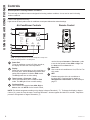 4
4
-
 5
5
-
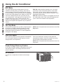 6
6
-
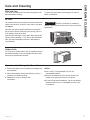 7
7
-
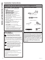 8
8
-
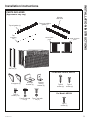 9
9
-
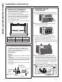 10
10
-
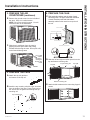 11
11
-
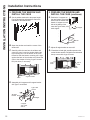 12
12
-
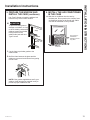 13
13
-
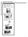 14
14
-
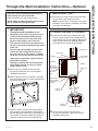 15
15
-
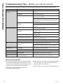 16
16
-
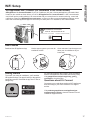 17
17
-
 18
18
-
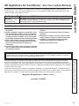 19
19
-
 20
20
-
 21
21
-
 22
22
-
 23
23
-
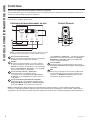 24
24
-
 25
25
-
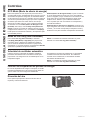 26
26
-
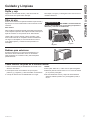 27
27
-
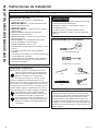 28
28
-
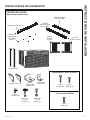 29
29
-
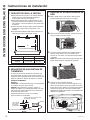 30
30
-
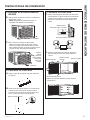 31
31
-
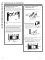 32
32
-
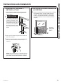 33
33
-
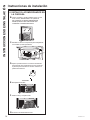 34
34
-
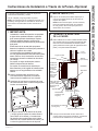 35
35
-
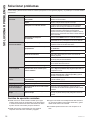 36
36
-
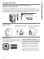 37
37
-
 38
38
-
 39
39
-
 40
40


GE AEG14AZ El manual del propietario
- Tipo
- El manual del propietario
en otros idiomas
- English: GE AEG14AZ Owner's manual
Artículos relacionados
-
GE AEW14AY El manual del propietario
-
-
-
-
-
GE AEG12AZ El manual del propietario
-
GE AKLK18AARB El manual del propietario
-
-
-