Dell PowerConnect M8024-K Guía de inicio rápido
- Categoría
- Redes
- Tipo
- Guía de inicio rápido

Dell PowerConnect
M8024-k Switch
Getting Started Guide
使用入门指南
入門指南
Guide de mise en route
Handbuch zum Einstieg
Panduan Pengaktifan
はじめに
시작 안내서
Guía de introducción
Başlangıç Kılavuzu
Guia de Primeiros Passos
Regulatory Model: PCM8024-k
ʪʩʸʣʮʺ
ʬ
ʩʧʺʤʣʥʡʲʤ


Dell PowerConnect
M8024-k Switch
Getting Started Guide
Regulatory Model: PCM8024-k

Notes
NOTE: A NOTE indicates important information that helps you make better use of
your computer.
____________________
Information in this publication is subject to change without notice.
© 2010 Dell Inc. All rights reserved.
Reproduction of these materials in any manner whatsoever without the written permission of Dell Inc.
is strictly forbidden.
Trademarks used in this text: Dell™, the DELL logo, PowerConnect™, OpenManage™, are
trademarks of Dell Inc. Microsoft
®
, Windows
®
are registered trademarks of Microsoft Corporation
in the United States and/or other countries.
Other trademarks and trade names may be used in this publication to refer to either the entities claiming
the marks and names or their products. Dell Inc. disclaims any proprietary interest in trademarks and
trade names other than its own.
Regulatory Model PCM8024-k
March 2011 P/N 7XG64 Rev. A00

Contents 3
Contents
1 Introduction . . . . . . . . . . . . . . . . . . . . . . . . 5
PowerConnect M8024-k Overview . . . . . . . . . . . . 5
2 Hardware Overview. . . . . . . . . . . . . . . . . . 6
Internal Ports. . . . . . . . . . . . . . . . . . . . . . . . 6
Front Panel
. . . . . . . . . . . . . . . . . . . . . . . . . 6
SFP+ Ports
. . . . . . . . . . . . . . . . . . . . . . 7
Expansion Slot
. . . . . . . . . . . . . . . . . . . . 7
USB Console Port
. . . . . . . . . . . . . . . . . . . 7
Port and System LEDs
. . . . . . . . . . . . . . . . 7
3 Installation . . . . . . . . . . . . . . . . . . . . . . . . 8
Site Preparation . . . . . . . . . . . . . . . . . . . . . . 8
Unpacking the Switch
. . . . . . . . . . . . . . . . . . . 9
Package Contents
. . . . . . . . . . . . . . . . . . 9
Unpacking Steps
. . . . . . . . . . . . . . . . . . . 9

4 Contents
4 Starting and Configuring the Switch . . . 10
Connecting a Switch to a Terminal . . . . . . . . . . . 11
Booting the Switch
. . . . . . . . . . . . . . . . . . . . 12
Performing the Initial Configuration
. . . . . . . . . . . 13
Initial Configuration Procedure
. . . . . . . . . . . 13
Example Session
. . . . . . . . . . . . . . . . . . 14
Next Steps
. . . . . . . . . . . . . . . . . . . . . 17

Getting Started Guide 5
Introduction
This document provides basic information about the Dell PowerConnect
M8024-k switches, including how to install a switch and perform the initial
configuration. For information about how to configure and monitor switch
features, see the User’s Configuration Guide, which is available on the Dell
Support website at http://support.dell.com/manuals for the latest updates on
documentation and firmware.
This document contains the following sections:
• Hardware Overview
• Installation
• Starting and Configuring the Switch
PowerConnect M8024-k Overview
The PowerConnect M8024-k is a Layer 3, 10-Gigabit Ethernet blade switch
that operates in the PowerEdge M1000e system. The M1000e system can
support up to 16 server blades and six PowerConnect M8024-k blade
switches.

6 Getting Started Guide
Hardware Overview
This section contains information about device characteristics and modular
hardware configurations for the PowerConnect M8024-k switches.
PowerConnect M8024-k has the following physical dimensions:
• 274.75 x 309.24 x 33.45 mm (W x D x H).
• 10.81 x 12.17 x 1.32 inches (W x D x H).
Internal Ports
PowerConnect M8024-k provides 16 internal 10-Gigabit Ethernet internal
ports. The 16 internal ports are connected to server blades through the
M1000e chassis mid-plane.
The M8024-k also provides an internal Ethernet interface—the out-of-band
(OOB) interface—which is dedicated to switch management. The OOB
interface is connected to the chassis management controller through the
chassis mid-plane. Traffic on this port is segregated from operational network
traffic on the switch ports and cannot be switched or routed to the
operational network.
Front Panel
The following image shows the PowerConnect M8024-k front panel:
Figure 1-1. PowerConnect M8024-k Front Panel
The front panel includes four SFP+ ports an expansion slot for 10-Gigabit
modules. The front panel also provides a USB serial console interface for
management functions and LEDs for port and system status.
USB Console PortSFP+ PortsExpansion Slot

Getting Started Guide 7
SFP+ Ports
PowerConnect M8024-k provides four SFP+ ports with SR, LR, and LRM
transceivers and SFP+ direct attach cables. SFP transceivers and direct
attach cables are sold separately.
Expansion Slot
The 10G expansion slot supports the following modules:
• SFP+ (four ports)
• CX-4 (three ports)
• 10GBASE-T (two ports)
The modules are sold separately.
USB Console Port
The USB console port is for management through an RS-232serial interface.
This port provides a direct connection to the switch and allows you to access
the CLI from a console terminal connected to the port through the provided
serial cable (with USB type-A to female DB-9 connectors).
The console port supports asynchronous data of eight data bits, one stop bit, no
parity bit, and no flow control. The default baud rate is 9600 bps.
Port and System LEDs
The front panel contains light emitting diodes (LEDs) that provide
information about the status of the PowerConnect M8024-k unit.
Figure 1-2. Front Panel LEDs
System Power LED
System Status LED

8 Getting Started Guide
Table 1-1 contains the status LED definitions:
Installation
Site Preparation
Before installing the switch or switches, make sure that the chosen
installation location meets the following site requirements:
•
Clearance
— There is adequate front and rear clearance for operator
access. Allow clearance for cabling, power connections, and ventilation.
•
Cabling
— The cabling is routed to avoid sources of electrical noise such
as radio transmitters, broadcast amplifiers, power lines, and fluorescent
lighting fixtures.
•
Ambient Temperature
— The ambient switch operating temperature
range is 10° to 35ºC (50° to 95ºF).
NOTE: Decrease the maximum temperature by 1°C (1.8°F) per 300 m (985 ft.)
above 900 m (2955 ft.).
•
Relative Humidity
— The operating relative humidity is 8% to 85%
(non-condensing) with a maximum humidity gradation of 10% per hour.
Table 1-1. PowerConnect M8024-k Power and Status LED Definitions
LED Color Definition
Green Power is being supplied to the switch.
Off The switch does not have power.
Blue The switch is operating normally.
Off The switch is powered off.
Amber A fault has occurred, or the switch is currently booting.

Getting Started Guide 9
Unpacking the Switch
Package Contents
When unpacking each switch, make sure that the following items are
included:
• One PowerConnect switch
• One USB type A-to-DB-9 female cable
• Getting Started Guide
• Safety and Regulatory Information
• Warranty and Support Information
• Software License Agreement
Unpacking Steps
NOTE: Before unpacking the switch, inspect the container and immediately report
any evidence of damage.
1
Place the container on a clean, flat surface and cut all straps securing the
container.
2
Open the container or remove the container top.
3
Carefully remove the switch from the container and place it on a secure
and clean surface.
4
Remove all packing material.
5
Inspect the product and accessories for damage.

10 Getting Started Guide
Starting and Configuring the Switch
The following flow chart provides an overview of the steps you use to perform
the initial configuration after the switch is unpacked and mounted.
Figure 1-3. Installation and Configuration Flow Chart
Connect Power
and Console
Power On
Choose Option 2
Boot Menu
(Special Functions)
Reboot
Loading Program
from Flash to RAM
Manual Initial
Configuration
Easy Setup Wizard
Configuration
Advanced
Configuration
Enter Boot
Menu?
Enter
Wizard?
Yes
No
Yes
No

Getting Started Guide 11
Connecting a Switch to a Terminal
After completing all external connections, connect a terminal to a switch to
configure the switch.
NOTE: Read the release notes for this product before proceeding. You can
download the release notes from the Dell Support website at
support.dell.com/manuals.
NOTE: We recommend that you obtain the most recent version of the user
documentation from the Dell Support website at http://support.dell.com/manuals.
To monitor and configure the switch via serial console, use the USB console
port on the front panel of the switch (see Figure 1-1) to connect it to a VT100
terminal or to a computer running VT100 terminal emulation software. The
console port is implemented as a data terminal equipment (DTE) connector.
The following equipment is required to use the console port:
• VT100-compatible terminal or a desktop or a portable computer with a
serial port running VT100 terminal emulation software,
such as Microsoft
HyperTerminal.
• A serial cable (provided) with a USB type-A connector for the console port
and DB-9 connector for the terminal.
Perform the following tasks to connect a terminal to the switch console port:
1
Connect the DB-9 connector on the serial cable to the terminal or
computer running VT100 terminal emulation software.
2
Configure the terminal emulation software as follows:
a
Select the appropriate serial port (for example, COM 1) to connect to
the console.
b
Set the data rate to 9600 baud.
c
Set the data format to 8 data bits, 1 stop bit, and no parity.
d
Set the flow control to none.
e
Set the terminal emulation mode to
VT100
.
f
Select Terminal keys for Function, Arrow, and Ctrl keys. Ensure that
the setting is for Terminal keys (not Microsoft Windows keys).

12 Getting Started Guide
NOTE: When using HyperTerminal with Microsoft Windows 2000, make sure
that you have Windows 2000 Service Pack 2 or later installed. With Windows
2000 Service Pack 2, the arrow keys function properly in HyperTerminal's
VT100 emulation. Go to microsoft.com for more information about Windows
2000 service packs.
3
Connect the USB connector on the cable directly to the switch console
port. The PowerConnect M8024-k console port is located on the right side
of the front panel, as shown in Figure 1-4.
Figure 1-4. PowerConnect M8024-k USB Console Port
Booting the Switch
When the power is turned on with the local terminal already connected, the
switch goes through a power-on self-test (POST). POST runs every time the
switch is initialized and checks hardware components to determine if the
switch is fully operational before completely booting. If POST detects a
critical problem, the program flow stops. If POST passes successfully, valid
firmware is loaded into RAM. POST messages are displayed on the terminal
and indicate test success or failure. The boot process runs for approximately
60 seconds.
You can invoke the Boot menu after the first part of the POST is completed.
From the Boot menu, you can perform configuration tasks such as resetting
the system to factory defaults, activating the backup image, or recovering a
password. For more information about the Boot menu functions, see the CLI
Reference Guide.
USB Console
Port

Getting Started Guide 13
Performing the Initial Configuration
The initial configuration procedure is based on the following assumptions:
• The PowerConnect switch was never configured before and is in the same
state as when you received it.
• The PowerConnect switch booted successfully.
• The console connection was established, and the
Dell Easy Setup Wizard
prompt appears on the screen of a VT100 terminal or terminal equivalent.
The initial switch configuration is performed through the console port. After
the initial configuration, you can manage the switch from the already-
connected console port or through a remote connection.
NOTE: The switch is not configured with a default user name, password, or IP
address.
Before setting up the initial configuration of the switch, obtain the following
information from your network administrator:
• The IP address to be assigned to the out-of-band (OOB) interface for
device management.
• The IP subnet mask for the OOB interface.
• The IP address of the OOB interface default gateway.
These settings are necessary to allow the remote management of the switch
through Telnet (Telnet client) or HTTP (Web browser).
Initial Configuration Procedure
You can perform the initial configuration by using the Dell Easy Setup
Wizard or by using the CLI. The wizard automatically starts when the switch
configuration file is empty. You can exit the wizard at any point by entering
[ctrl+z], but all configuration settings specified will be discarded, and the
switch will use the default values.
NOTE: If you do not run the Easy Setup Wizard or do not respond to the initial Easy
Setup Wizard prompt within 60 seconds, the switch enters CLI mode.
For more information about performing the initial configuration by using the
CLI, see the CLI Reference Guide. This Getting Started Guide shows how to
use the Easy Setup Wizard for initial switch configuration. The wizard sets up
the following configuration on the switch:

14 Getting Started Guide
• Establishes the initial privileged user account with a valid password. The
wizard configures one privileged user account during the setup.
• Enables CLI login and HTTP access to use the local authentication setting
only.
• Sets up the IP address for the OOB interface.
• Sets up the SNMP community string to be used by the SNMP manager at
a given IP address. You may choose to skip this step if SNMP management
is not used for this switch.
Example Session
This section describes an Easy Setup Wizard session. The following values are
used by the example session:
• SNMP is not enabled.
• The default user name,
root
, is accepted and a password of
admin123
is
entered. The Wizard does not display the password as it is entered.
• The OOB management interface uses
192.168.2.1
for IP address
assignment.
NOTE: In the example below, the possible user options or default values are
enclosed in [ ]. If you press <Enter> with no options defined, the default value is
accepted. Help text is in parentheses.
The following example contains the sequence of prompts and responses
associated with running an example Dell Easy Setup Wizard session, using
the input values listed above.
After the switch completes the POST and is booted, the following text is
displayed:
(Unit 1 - Waiting to select management unit)>
Applying Global configuration, please wait ...
Welcome to Dell Easy Setup Wizard
The Setup Wizard guides you through the initial switch
configuration, and gets you up and running as quickly
as possible. You can skip the setup wizard, and enter
CLI mode to manually configure the switch. You must
respond to the next question to run the setup wizard
within 60 seconds, otherwise the system will continue

Getting Started Guide 15
with normal operation using the default system
configuration. Note: You can exit the setup wizard at
any point by entering [ctrl+z].
Would you like to run the setup wizard (you must
answer this question within 60 seconds)? [Y/N] y
First:
Do you want to select the operational mode as Simple
Mode? [Y/N] y
Step 1:
The system is not setup for SNMP management by
default. To manage the switch using SNMP (required for
Dell Network Manager) you can
. Set up the initial SNMP version 2 account now.
. Return later and setup other SNMP accounts. (For
more information on setting up an SNMP version 1
or 3 account, see the user documentation).
Would you like to setup the SNMP management interface
now? [Y/N] n
Step 2:
Now we need to setup your initial privilege (Level 15)
user account. This account is used to login to the CLI
and Web interface. You may setup other accounts and
change privilege levels later. For more information on
setting up user accounts and changing privilege
levels, see the user documentation.
To setup a user account:
Please enter the user name. [root]:
Please enter the user password:
Please reenter the user password:

16 Getting Started Guide
Step 3:
Next, IP addresses are setup on the OOB (Out-Of-Band)
Interface and/or the VLAN1 routing interface.
You can use these IP addresses to access the CLI, Web
interface, or SNMP interface of the switch.
To access the switch through any Management Interface
you can
. Setup the IP address for the Management Interface.
. Setup the default gateway if IP address is
manually configured on both routing and OOB
interface.
Would you like to setup the Out-Of-Band interface now?
[Y/N] y
Please enter the IP address of the device (A.B.C.D) or
enter "DHCP" (without the quotes) to automatically
request an IP address from the network DHCP server.
[192.168.2.1]:
Please enter the IP subnet mask (A.B.C.D or /nn).
[255.255.255.0]:
This is the configuration information that has been
collected:
Operational Mode = Simple
User Account setup = root
Password = ********
Out-of-band IP address = 192.168.2.1 255.255.255.0
Final Step:
If the information is correct, please enter (Y) to
save the configuration, and copy the settings to the
start-up configuration file. If the information is
incorrect, enter (N) to discard the configuration and
restart the wizard: [Y/N] y

Getting Started Guide 17
Thank you for using the Dell Easy Set up Wizard. You
will now enter CLI mode.
Applying Interface configuration, please wait ...
console>
Next Steps
After completing the initial configuration described in this section, you can
connect any of the front-panel switch ports to your production network for
in-band remote management.
If you specified DHCP for the OOB management interface IP address, the
interface will acquire its IP address from a DHCP server on the network. To
discover the dynamically-assigned IP address, use the console port connection
to issue the following command:
show ip interface out-of-band.
To access the Dell OpenManage Switch Administrator interface, enter the
OOB management interface IP address into the address field of a Web
browser. For remote management access to the CLI, enter the OOB
management interface IP address into a Telnet or SSH client. Alternatively,
you can continue to use the console port for local CLI access to the switch.
Your PowerConnect M8024-k switch supports basic switching features such as
VLANs, 802.1X, RADIUS and TACACS+. For more information on the
features supported in Simple mode, refer to Simple Switch Mode: Port
Aggregator Feature White Paper.
If the switch is configured to operate in Normal mode, it can also support
features such as spanning tree protocol, as well as advanced Layer 3 features
such as dynamic routing and multicast. Use the web-based management
interface or the CLI to configure the features your network requires. For
information about how to configure the switch features, see the User’s
Configuration Guide or CLI Reference Guide available on the support site:
http://support.dell.com/manuals.

18 Getting Started Guide

Dell PowerConnect
M8024-k 交换机
使用入门指南
管制型号:
PCM8024-k

注
注:“注”表示可以帮助您更好地使用计算机的重要信息。
____________________
本出版物中的信息如有更改,恕不另行通知。
© 2010 Dell Inc.
版权所有,翻印必究。
未经
Dell Inc.
书面许可,严禁以任何形式对这些材料进行复制。
本文中使用的商标:
Dell
™
, DELL
徽标
, PowerConnect
™
, OpenManage
™
,
是
Dell Inc.
的商
标
Microsoft
®
, Windows
®
是
Microsoft Corporation
在美国和
/
或其它国家或地区的注册商标。
本出版物中述及的其它商标和产品名称是指拥有相应商标和产品名称的公司或其制造的
产品。
Dell Inc.
对其它公司的商标和产品名称不拥有任何所有权。
管制型号
PCM8024-k
2011
年
3
月
P/N 7XG64 Rev. A00

目录 21
目录
1 简介 . . . . . . . . . . . . . . 23
PowerConnect M8024-k
概览
. . . . . . . . . . . . . 23
2 硬件概览 . . . . . . . . . . . . 24
内部端口 . . . . . . . . . . . . . . . . . . . . . . 24
前面板
. . . . . . . . . . . . . . . . . . . . . . . 24
SFP+ 端口 . . . . . . . . . . . . . . . .
25
扩充槽 . . . . . . . . . . . . . . . . .
25
USB 控制台端口 . . . . . . . . . . . . .
25
端口和系统 LED
. . . . . . . . . . . . . . . . 25
3 安装 . . . . . . . . . . . . . . 26
现场准备 . . . . . . . . . . . . . . . . . . . . . . 26
打开交换机包装
. . . . . . . . . . . . . . . . . . . 27
包装箱物品 . . . . . . . . . . . . . . .
27
打开包装步骤 . . . . . . . . . . . . . .
27


使用入门指南 23
简介
本说明文件介绍有关
Dell PowerConnect M8024-k
交换机的基本信息,包
括如何安装交换机并进行初始配置。
有关如何配置和监测交换机功能的
信息,请参阅
Dell
支持
Web
站点上的
Users Configuration Guide, (
用户配
置指南)。要获取有关说明文件及固件的最新更新,请访问该站点,网址
为
http://support.dell.com/manuals.
本说明文件包含以下部分:
•
硬件概览
•
安装
•
启动和配置交换机
PowerConnect M8024-k
概览
PowerConnect M8024-k
是在
PowerEdge M1000e
系统上运行的第
3
层
10
千兆位以太网刀片式交换机。
M1000e
系统可支持多达
16
个服务器刀片
和
6
个
PowerConnect M8024-k
刀片式交换机。

24 使用入门指南
硬件概览
本节包含有关
PowerConnect M8024-k
交换机设备特性和模块化硬件配置
的信息。
PowerConnect M8024-k
的物理尺寸如下所示:
•
274.75 x 309.24 x 33.45
毫米(宽
x
厚
x
高)。
•
10.81 x 12.17 x 1.32
英寸(宽
x
厚
x
高)。
内部端口
PowerConnect M8024-k
提供
16
个
10
千兆位以太网内部端口。这
16
个内
部端口通过
M1000e
机箱中间面板连接到服务器刀片。
M8024-k
还提供了内部以太网接口,即带外
(OOB)
接口。该接口专用于
进行交换机管理。
OOB
接口通过机箱中间面板连接到机箱管理控制器。
此端口上的通信与交换机端口上的运行网络通信是分开的,并且不能切换
或路由到运行网络。
前面板
下图表示
PowerConnect M8024-k
前面板:
图
1-1. PowerConnect M8024-k
前面板
前面板包含
4
个
SFP+
端口以及
1
个
10
千兆位模块的扩充槽。前面板还
提供
1
个用于管理功能和端口以及系统状态
LED
的
USB
串行控制台
接口。
USB 控制台端口SFP+ 端口扩充槽

使用入门指南 25
SFP+
端口
PowerConnect M8024-k
提供
4
个具有
SR
、
LR
及
LRM
收发器的
SFP+
端
口和
SFP+
直连电缆。
SFP
收发器和直连电缆单独出售。
扩充槽
10G
扩充槽支持下列模块:
•
SFP+
(
4
个端口)
•
CX-4
(
3
个端口)
•
10GBASE-T
(
2
个端口)
这些模块单独出售。
USB
控制台端口
USB
控制台端口用于通过
RS-232
串行接口进行管理。可以借助此端口直
接连接到交换机,并可从通过提供的串行电缆连接到此端口(
USB A
类到
内孔
DB-9
连接器)的控制台终端来访问
CLI
。
控制台端口支持八个数据位、一个停止位、无奇偶校验位以及无流控制的异
步数据。默认波特率为
9600 bps
。
端口和系统
LED
前面板包含若干发光二极管
(LED)
,用于提供关于
PowerConnect M8024-k
单元的状态信息
。
图
1-2.
前面板
LED
系统电源 LED
系统状态 LED

26 使用入门指南
表
1-1
包含了状态
LED
说明:
安装
现场准备
安装交换机之前,请确保选择的安装位置满足以下现场要求:
•
空间
正面和背面有足够空间供操作员进行操作。留出用于布线、电源
连接以及通风的空间。
•
布线
布线应远离电气噪音干扰源,如无线电发射器、广播放大器、电
线以及荧光照明装置。
•
环境温度
交换机的运行环境温度范围为
10
到
35C (50
到
95F).
注:在 900 米(2955 英尺)以上,每升高 300 米(985 英尺)最高温度
下降 1C (1.8F)。
•
相对湿度
运行相对湿度为
8%
到
85%
(非冷凝),最大湿度变化梯度
为每小时
10%
。
表
1-1. PowerConnect M8024-k
电源和状态
LED
说明
LED
颜色
定义
绿色 正在为交换机供电。
关闭 交换机已断电。
蓝色 交换机工作正常。
关闭 交换机电源关闭。
琥珀色 出现故障,或交换机当前正在引导。

使用入门指南 27
打开交换机包装
包装箱物品
打开每台交换机的包装时,请确保其中包含以下物品:
•
一台
PowerConnect
交换机
•
一根
USB A
类至
DB-9
内孔电缆
•
使用入门指南
•
安全和管制信息
•
保修和支持信息
•
软件许可协议
打开包装步骤
注:在打开交换机的包装之前,先检查包装盒,如有任何损坏迹象,请立
即报告。
1
将包装盒放在整洁平坦的表面上,然后剪断固定包装盒的所有包装
带。
2
打开包装盒或取下包装盒盖。
3
从包装盒中小心取出交换机,然后将其放在稳固整洁的表面上。
4
取出所有包装材料。
5
检查产品及附件是否出现损坏。

28 使用入门指南
启动和配置交换机
以下流程图概述了在打开交换机包装并安装好交换机之后,用于进行初始
配置的步骤。
图
1-3.
安装和配置流程图
连接电源和控
制台
开机
选择选项 2
引导菜单
(特殊功能)
重新引导
将程序从闪存载
入到 RAM
手动初始配置
简易安装向
导配置
高级配置
进入引导
菜单?
进入
向导?
是
否
是
否

使用入门指南 29
将交换机连接至终端
完成所有外部连接后,将终端连接至交换机以配置该交换机。
注:在继续操作之前,请阅读本产品的版本注释。可以从 Dell 支持 Web 站
点 support.dell.com/manuals 下载版本注释。
注:我们建议您从 Dell 支持 Web 站点 http://support.dell.com/manuals 获取最
新版本的用户说明文件。
要通过串行控制台监测和配置交换机,请使用交换机前面板上的
USB
控
制台端口(请参阅图
1-1
),将交换机连接至
VT100
终端或正在运行
VT100
终端仿真软件的计算机。控制台端口可用作数据终端设备
(DTE)
连接器。
要使用控制台端口,需要以下设备:
•
VT100
兼容终端,或者一台配备串行端口并运行
VT100
终端仿真软件
(
如
Microsoft HyperTerminal
)的台式机或便携式计算机。
•
一根串行电缆(附带),带有连接控制台端口的
USB A
类连接器和连
接终端的
DB-9
连接器。
要将终端连接至交换机控制台端口,请执行以下任务:
1
将串行电缆上的
DB-9
连接器与运行
VT100
终端仿真软件的终端或计
算机相连。
2
按照以下步骤配置终端仿真软件:
a
选择适当的串行端口(例如
COM 1
)连接到控制台。
b
将数据速率设置为
9600
波特。
c
将数据格式设置为
8
个数据位、
1
个停止位以及无奇偶校验。
d
将流控制设置为
none
(无)。
e
将终端仿真模式设置为
VT100
。
f
选择终端键作为功能键、箭头键和
Ctrl
键。确保此设置适用于终
端键(而不是
Microsoft Windows
键)。
注:在 Microsoft Windows 2000 中使用超级终端时,请确保已安装
Windows 2000 Service Pack 2 或更高版本。使用 Windows 2000 Service
Pack 2 可以确保箭头键在超级终端的 VT100 仿真中正常工作。有关
Windows 2000 Service Pack 的详情,请访问 microsoft.com。
3
将电缆上的
USB
连接器直接连接到交换机控制台端口。
PowerConnect
M8024-k
控制台端口位于前面板右侧,如图
1-4
中所示。

30 使用入门指南
图
1-4. PowerConnect M8024-k USB
控制台端口
引导交换机
打开电源并连接本地终端后,交换机将进行开机自测
(POST)
。
POST
在
每次初始化交换机时进行,用于检查硬件组件,以确定交换机在完全引导
之前是否完全正常运转。如果
POST
检测到严重问题,程序流就会停止。
如果
POST
成功通过,将载入一个有效的固件到
RAM
中。
POST
信息显
示在终端上,用于指出自测是否成功。引导过程大约运行
60
秒。
在
POST
第一部分完成后,可以调用
Boot
(引导)菜单。从
Boot
(引
导)菜单中,您可以执行配置任务,例如将系统重置为出厂默认值、激活
备份映像或者恢复密码。有关
Boot
(引导)菜单功能的详情,请参阅
《
CLI
参考指南》。
进行初始配置
初始配置步骤基于以下假设条件:
•
PowerConnect
交换机此前从未进行过任何配置,其状态与收到时
相同。
•
PowerConnect
交换机引导成功。
•
控制台连接已建立,并且
Dell
简易安装向导
提示信息显示在
VT100
终端或同等终端设备的屏幕上。
通过控制台端口执行初始交换机配置。完成初始配置后,可以通过已连接
的控制台端口或远程连接管理交换机。
注:交换机未配置默认的用户名、密码和 IP 地址。
USB 控制台
端口

使用入门指南 31
在设置交换机的初始配置之前,从网络管理员处获得以下信息:
•
要分配给带外
(OOB)
接口进行设备管理的
IP
地址。
•
OOB
接口的
IP
子网掩码。
•
OOB
接口默认网关的
IP
地址。
要通过
Telnet
(
Telnet
客户端)或
HTTP
(
Web
浏览器)来远程管理交换
机,需要这些设置。
初始配置步骤
可以使用
Dell
简易安装向导或
CLI
来进行初始配置。当交换机配置文件
为空时,将自动启动该向导。可以随时通过输入
[ctrl+z]
退出向导,但指
定的所有配置设置都将被丢弃,交换机将使用默认值。
注:如果不运行简易安装向导或在 60 秒内没有响应初始简易安装向导提
示,交换机会进入 CLI 模式。
有关使用
CLI
进行初始配置的详情,请参阅《
CLI
参考指南》。本使用
入门指南说明如何使用简易安装向导来进行初始交换机配置。该向导设置
交换机的以下配置:
•
建立拥有权限的初始用户帐户以及有效的密码。在安装过程中,该向
导将配置一个具有权限的用户帐户。
•
启用
CLI
登录和
HTTP
访问,以便仅使用本地验证设置。
•
设置
OOB
接口的
IP
地址。
•
设置
SNMP
管理器在指定
IP
地址要使用的
SNMP
团体字符串。如果
该交换机不使用
SNMP
管理,则可以选择跳过这一步。
示例会话
本节介绍了一个简易安装向导会话。示例会话将使用以下值:
•
SNMP
未启用。
•
默认用户名
root
已接受,而且密码
admin123
已输入。在输入密码
时,向导不会显示密码。
•
OOB
管理接口使用
192.168.2.1
来分配
IP
地址。
注:在以下示例中,可能的用户选项或默认值包括在 [ ] 中。如果未定义选
项,按 <Enter> 键将接受默认值。帮助文本在括号中。
以下示例包含与使用上面列出的输入值运行
Dell Easy Setup Wizard
(
Dell
简易安装向导)示例会话相关的提示序列和响应。

32 使用入门指南
交换机完成
POST
并引导后,将显示以下文本信息:
(Unit 1 - Waiting to select management unit)>
Applying Global configuration, please wait ...
Welcome to Dell Easy Setup Wizard
The Setup Wizard guides you through the initial switch
configuration, and gets you up and running as quickly
as possible. You can skip the setup wizard, and enter
CLI mode to manually configure the switch. You must
respond to the next question to run the setup wizard
within 60 seconds, otherwise the system will continue
with normal operation using the default system
configuration. Note: You can exit the setup wizard at
any point by entering [ctrl+z].
Would you like to run the setup wizard (you must
answer this question within 60 seconds)? [Y/N] y
First:
Do you want to select the operational mode as Simple
Mode? [Y/N] y
Step 1:
The system is not setup for SNMP management by
default. To manage the switch using SNMP (required for
Dell Network Manager) you can
. Set up the initial SNMP version 2 account now.
. Return later and setup other SNMP accounts. (For
more information on setting up an SNMP version 1
or 3 account, see the user documentation).
Would you like to setup the SNMP management interface
now? [Y/N] n
Step 2:
Now we need to setup your initial privilege (Level 15)
user account. This account is used to login to the CLI
and Web interface. You may setup other accounts and
change privilege levels later. For more information on
setting up user accounts and changing privilege
levels, see the user documentation.

使用入门指南 33
To setup a user account:
Please enter the user name. [root]:
Please enter the user password:
Please reenter the user password:
Step 3:
Next, IP addresses are setup on the OOB (Out-Of-Band)
Interface and/or the VLAN1 routing interface.
You can use these IP addresses to access the CLI, Web
interface, or SNMP interface of the switch.
To access the switch through any Management Interface
you can
. Setup the IP address for the Management Interface.
. Setup the default gateway if IP address is
manually configured on both routing and OOB
interface.
Would you like to setup the Out-Of-Band interface now?
[Y/N] y
Please enter the IP address of the device (A.B.C.D) or
enter "DHCP" (without the quotes) to automatically
request an IP address from the network DHCP server.
[192.168.2.1]:
Please enter the IP subnet mask (A.B.C.D or /nn).
[255.255.255.0]:
This is the configuration information that has been
collected:
Operational Mode = Simple
User Account setup = root
Password = ********
Out-of-band IP address = 192.168.2.1 255.255.255.0

34 使用入门指南
Final Step:
If the information is correct, please enter (Y) to
save the configuration, and copy the settings to the
start-up configuration file. If the information is
incorrect, enter (N) to discard the configuration and
restart the wizard: [Y/N] y
Thank you for using the Dell Easy Set up Wizard. You
will now enter CLI mode.
Applying Interface configuration, please wait ...
console>
接下来的步骤
完成本节所述的初始配置后,您可以将任意前面板交换机端口连接到生产
网络以便进行带内远程管理。
如果指定
DHCP
来分配
OOB
管理接口
IP
地址,则该接口会从网络上的
DHCP
服务器获得
IP
地址。要发现动态分配的
IP
地址,请使用控制台端
口连接来发出以下命令:
show ip interface out-of-band
。
要访问
Dell OpenManage Switch Administrator
界面,请在
Web
浏览器
的地址字段中输入
OOB
管理接口
IP
地址。要对
CLI
进行远程管理访
问,请在
Telnet
或
SSH
客户端中输入
OOB
管理接口
IP
地址。或者,可
以继续使用控制台端口对交换机进行本地
CLI
访问。
您的
PowerConnect M8024-k
交换机支持基本的交换功能,如
VLAN
、
802.1X
、
RADIUS
和
TACACS+
。有关在简单模式中支持的功能的详情,
请参阅简单交换机模式:端口聚合器功能白皮书。
如果将交换机配置为在普通模式下工
作,也能支持诸如生成树协议之类的
功能,以及高级第
3
层功能(如动态路由和多点传送)。使用基于
Web
的管理接口或
CLI
可配置您的网络需要的功能。
有关如何配置交换机功
能的信息,请参阅
Users Configuration Guide (
用户配置指南)或
《
CLI
参考指南》
,这些资料可从以下支持站点获取:
http://support.dell.com/manuals
。

Dell PowerConnect
M8024-k 交換機
入門指南
管制型號: PCM8024-k

註
註:「註」指出可協助您善加利用電腦的重要資訊。
____________________
對本出版物中所含資訊之變更恕不另行通知。
© 2010 Dell Inc. 版權所有,翻印必究。
未經 Dell Inc. 之書面許可,不得以任何方式重製這些材料。
本文所用商標: Dell™、 DELL 標誌、 PowerConnect™ 以及 OpenManage™ 是 Dell Inc. 的
商標。 Microsoft
®
、 Windows
®
是在美國和 / 或其他國家 / 地區的註冊商標。
本出版物所述及之其他商標或品牌名稱,均各自分屬其商標或產品名稱之申請者或擁有者所
擁有。Dell Inc. 對本公司之外的商標和產品名稱不擁有任何專有權。
管制型號 PCM8024-k
2011 年 3 月 P/N 7XG64 Rev. A00

目錄 37
目錄
1 簡介 . . . . . . . . . . . . . . . . . . . . . . . . . 39
PowerConnect M8024-k 概 . . . . . . . . . . . . . . 39
2 硬體概觀 . . . . . . . . . . . . . . . . . . . . . . 40
內部連接埠 . . . . . . . . . . . . . . . . . . . . . 40
前面板
. . . . . . . . . . . . . . . . . . . . . . . 40
SFP+ 連接埠
. . . . . . . . . . . . . . . . . . 41
擴充插槽
. . . . . . . . . . . . . . . . . . . . 41
USB 主控台連接埠
. . . . . . . . . . . . . . . 41
連接埠和系統 LED
. . . . . . . . . . . . . . . 41
3 安裝 . . . . . . . . . . . . . . . . . . . . . . . . . 42
現場準備 . . . . . . . . . . . . . . . . . . . . . . 42
拆開交換機包裝
. . . . . . . . . . . . . . . . . . . 43
包裝箱物品
. . . . . . . . . . . . . . . . . . 43
拆開包裝的步驟
. . . . . . . . . . . . . . . . 43

38 目錄
4 啟動和設定交換機 . . . . . . . . . . . . . . . 44
將交換機連接至終端 . . . . . . . . . . . . . . . . 45
啟動交換機
. . . . . . . . . . . . . . . . . . . . . 46
進行初始組態
. . . . . . . . . . . . . . . . . . . . 46
初始組態程序
. . . . . . . . . . . . . . . . . 47
範例作業階段
. . . . . . . . . . . . . . . . . 47
接下來的步驟
. . . . . . . . . . . . . . . . . 50

入門指南 39
簡介
本文件提供 Dell PowerConnect M8024-k 交換機的基本資訊,包括如何安
裝交換機並進行初始組態。 如需有關如何設定和監控交換機功能的資
訊,請參閱 Dell 支援網站上的 Users Configuration Guide, ( 使用者組態指
南 )。要獲取有關文件及韌體的最新更新,請造此網站,網址為
http://support.dell.com/manuals.
本文件包含以下部分:
•
硬體概觀
•
安裝
•
啟動和設定交換機
PowerConnect M8024-k 概
PowerConnect M8024-k 是在 PowerEdge M1000e 系統上行的第三層 10
Gigabit Ethernet 刀片交換機。M1000e 系統可支援多達 16 個伺服器刀片
和 6 個 PowerConnect M8024-k 刀片交換機。

40 入門指南
硬體概觀
本節包含有關 PowerConnect M8024-k 交換機裝置特性和模組化硬體組態
的資訊。
PowerConnect M8024-k 具有以下物理尺寸:
• 274.75 x 309.24 x 33.45
毫米
(
寬
x
厚
x
高
)
• 10.81 x 12.17 x 1.32
英寸
(
寬
x
厚
x
高
)
內部連接埠
PowerConnect M8024-k 提供 16 個內部 10 Gigabit Ethernet 內部連接埠。
這 16 個內部連接埠透過 M1000e 機殼中間面板連接到伺服器刀片。
M8024-k 還提供內部 Ethernet 介面,即頻外 (OOB) 介面。該介面專用於
交換機管理。OOB 介面透過機殼中間面板連接到機殼管理控制器。此連
接埠上的資訊流量與交換機連接埠上的作業網路資訊流量是分開的,並且
不能切換或路由到作業網路。
前面板
以下影像顯示了 PowerConnect M8024-k 前面板:
圖 1-1. PowerConnect M8024-k 前面板
前面板包含 4 個 SFP+ 連接埠和 1 個 10 Gigabit 模組的擴充插槽。前面板
還提供了一個用來管理功能和連接埠及系統狀態 LED 的 USB 序列主控台
介面。
USB 主控台連接埠SFP+ 連接埠擴充插槽

入門指南 41
SFP+ 連接埠
PowerConnect M8024-k 提供 4 個具有 SR、LR 和 LRM 收發器及 SFP+ 直
接連接電纜的 SFP+ 連接埠。SFP 收發器和直接連接電纜單獨出售。
擴充插槽
10G 擴充插槽支援下列模組:
• SFP+ (4
個連接埠
)
•CX-4 (3
個連接埠
)
• 10GBASE-T (2
個連接埠
)
這些模組單獨出售。
USB 主控台連接埠
USB 主控台連接埠用於透過 RS-232 序列介面進行管理。可以借助此連接
埠直接連接到交換機,並從透過提供的序列電纜 ( 具有 USB A 至內孔
DB-9 連接器 ) 連接到此連接埠的主控台終端來存取 CLI。
主控台連接埠支援八個資料位元、一個停止位元、無同位檢查位以及無流量
控制的非同步資料。預設傳輸速率為
9600 bps
。
連接埠和系統 LED
前面板包含若干發光二極體
(LED)
,用於提供有關
PowerConnect M8024-k
單元的資訊
。
圖 1-2. 前面板 LED
系統電源 LED
系統狀態 LED

42 入門指南
表 1-1 包含狀態 LED 定義:
安裝
現場準備
安裝交換機之前,請確保選擇的安裝位置滿足以下現場要求:
•
空間
交換機前後有足夠的空間供操作人員操作。留出用於布線、電源
連接以及通風的空間。
•
布線
布線時應避開電噪音源,如無線電發射器、廣播擴音器、電線以
及螢光燈具等。
• 環境溫度 交換機運作的環境溫度範圍在 10° 到 35°C
(50° 到 95°F)。
註:在 900 米 (2955 英尺 ) 以上,每升高 300 米 (985 英尺 ) 最高溫度
下降 1
°
C (1.8
°
F)。
•
相對溼度
運作的相對溼度為
8%
到
85% (
非冷凝
)
,最大濕度變化梯度
為每小時
10%
。
表 1-1. PowerConnect M8024-k 電源和狀態 LED 定義
LED
顏色 定義
綠色 交換機已接通電源。
熄滅 交換機未接通電源。
藍色 交換機正常運作。
熄滅 交換機電源關閉。
黃色 發生故障或交換機目前正在啟動。

入門指南 43
拆開交換機包裝
包裝箱物品
拆開每台交換機的包裝時,請確保其中包含以下物品:
•
一台
PowerConnect
交換機
•
一根
USB A
至
DB-9
的內孔電纜
•
入門指南
•
安全和管制資訊
•
保固和支援資訊
•
軟體授權協議
拆開包裝的步驟
註:在拆開交換機的包裝之前,先檢查包裝盒,如有任何損壞跡象,請立
即報告。
1
將包裝盒放在整潔平坦的表面上,然後剪斷固定包裝盒的所有包
裝帶。
2
拆開包裝盒或取下包裝盒蓋。
3
從包裝盒中小心地取出交換機,然後將其放在穩定且整潔的表面上。
4
取出所有包裝材料。
5
檢查產品及附件是否有損壞。

44 入門指南
啟動和設定交換機
以下流程圖概述了在拆開交換機包裝並安裝好交換機之後,進行初始組態
所使用的步驟。
圖 1-3. 安裝和設定流程圖
連接電源和
主控台
開機
選擇選項 2
動功能表
( 特殊功能 )
重新動
將程式從快閃記
憶體載入 RAM
手動初始組態
簡易設定精
靈組態
進階組態
進入動
功能表?
進入
精靈?
是
否
是
否

入門指南 45
將交換機連接至終端
完成所有外部連接之後,將終端連接至交換機以設定該交換機。
註:在繼續操作之前,請閱讀本產品的版本說明。版本說明可以從 Dell 支
援網站 support.dell.com/manuals 下載。
註:建議從 Dell 支援網站 http://support.dell.com/manuals 獲取最新版本的使
用者文件。
若要透過序列主控台監控和設定交換機,請使用交換機前面板上的 USB
主控台連接埠 ( 請參閱圖 1-1),將交換機連接至 VT100 終端或正在執行
VT100 終端模擬軟體的電腦。主控台連接埠可用作資料終端設備 (DTE)
連接器。
若要使用主控台連接埠,需要以下設備:
• VT100
相容終端,或者一台配備序列連接埠並執行
VT100
終端模擬軟
體
(
如 Microsoft HyperTerminal) 的桌上型電腦或便式電腦。
•
一根序列電纜
(
附帶
)
,帶有連接控制台連接埠的
USB A
連接器和連接
終端的
DB-9
連接器。
執行下列工作以將終端連接至交換機主控台連接埠:
1
將序列電纜上的
DB-9
連接器與執行
VT100
終端模擬軟體的終端或電
腦相連。
2
按照以下步驟設定終端模擬軟體:
a
選取適當的序列連接埠
(
例如
COM 1)
以連接到主控台。
b
將資料速率設定為
9600
鮑。
c
將資料格式設定為
8
個資料位元、
1
個停止位元以及無同位檢查。
d
將流量控制設定為
none (
無
)
。
e
將終端模擬模式設定為
VT100
。
f
對於功能鍵、方向鍵和
Ctrl
鍵,請選擇終端機按鍵。確保此設定
適用於終端機按鍵
(
而不是
Microsoft Windows
按鍵
)
。
註:在 Microsoft Windows 2000 中使用超級終端時,請確保已安裝
Windows 2000 Service Pack 2 或更高版本。使用 Windows 2000 Service
Pack 2 可以確保箭頭鍵在超級終端的 VT100 模擬中正常工作。請瀏覽
microsoft.com 以獲得 Windows 2000 Service Pack 的更多資訊。
3
將電纜上的
USB
連接器直接連接到交換機主控台連接埠。
PowerConnect M8024-k
主控台連接埠位於前面板右側,如圖
1-4
中所示。

46 入門指南
圖 1-4. PowerConnect M8024-k USB 主控台連接埠
啟動交換機
打開電源並連接本機終端後,交換機將進行開機自我測試 (POST)。
POST 在每次初始化交換機時執行,目的是檢查硬體元件,以確定交換機
在完全動之前是否完全正常運作。如果 POST 檢測到嚴重問題,程式流程
就會停止。如果 POST 成功通過,將載入一個有效的韌體到 RAM 中。
POST 訊息顯示在終端上,用於指出自我測試是否成功。動程序大約
執行 60 秒。
在 POST 第一部分完成後,可以叫用 Boot ( 動 ) 功能表。從 Boot ( 動 ) 功
能表中,您可以執行組態工作,例如將系統重設為出廠預設值、啟動備份
影像或者復原密碼。有關 Boot ( 動 ) 功能表功能的更多資訊,請參閱
《CLI Reference Guide》 (CLI 參考指南 )。
進行初始組態
初始組態程序基於以下假設條件:
• PowerConnect
交換機此前從未進行過任何組態,其狀態與收到時
相同。
• PowerConnect
交換機已成功啟動。
•
主控台連線已建立,並且
Dell 簡易設定精靈
提示訊息顯示在
VT100
終端或對應終端裝置的螢幕上。
透過主控台連接埠執行初始交換機組態。完成初始組態後,您可以透過已
連接的主控台連接埠或遠端連線來管理交換機。
註:交換機未組態預設的使用者名稱、密碼和 IP 位址。
USB 主控台
連接埠

入門指南 47
在設定交換機的初始組態之前,從網路管理員處獲得以下資訊:
•
要指定到頻外
(OOB)
介面進行裝置管理的
IP
位址。
• OOB
介面的
IP
子網路遮罩。
• OOB
介面預設閘道的
IP
位址。
若要透過 Telnet (Telnet 用戶端 ) 或 HTTP (Web 瀏覽器 ) 來遠端管理交換
機,需要這些設定。
初始組態程序
可以使用 Dell 簡易設定精靈或 CLI 來執行初始組態。當交換機組態檔為
空時,將自動啟動該精靈。可以隨時透過輸入 [ctrl+z] 結束精靈,但指定
的所有組態設定都將被捨棄,交換機將使用預設值。
註:如果不執行簡易設定精靈或在 60 秒內沒有回應初始簡易設定精靈提示
訊息,交換機會進入 CLI 模式。
有關使用 CLI 進行初始組態的更多資訊,請參閱《CLI Reference Guide》
(CLI 參考指南 )。本入門指南說明如何使用簡易設定精靈來執行初始交換
機組態。該精靈設定交換機的以下組態:
•
建立具有權限的初始使用者帳戶及有效密碼。在設定過程中,該精靈
將設定一個具有權限的使用者帳戶。
•
啟用
CLI
登入和
HTTP
存取,以便僅使用本機驗證設定。
•
設定
OOB
介面的
IP
位址。
•
設定
SNMP
管理員在指定
IP
位址要使用的
SNMP
社群字串。如果交
換機不使用
SNMP
管理,則可以選擇跳過這一步。
範例作業階段
本節介紹一個簡易設定精靈作業階段。範例作業階段將使用以下值:
•SNMP
沒有啟用。
•
預設使用者名稱
root
已接受,且密碼
admin123
已輸入。在輸入密碼
時,精靈不會顯示密碼。
• OOB
管理介面使用
192.168.2.1
來指定
IP
位址。
註:在以下範例中,可能的使用者選項或預設值包括在 [ ] 中。如果未定義
選項,按 <Enter> 鍵將接受預設值。說明文字在括弧中。
以下範例包含與使用上面列出的輸入值執行 Dell 簡易設定精靈範例作業
階段相關的提示順序和回應。

48 入門指南
交換機完成 POST 並啟動後,將顯示以下文字:
(Unit 1 - Waiting to select management unit)>
Applying Global configuration, please wait ...
Welcome to Dell Easy Setup Wizard
The Setup Wizard guides you through the initial switch
configuration, and gets you up and running as quickly
as possible. You can skip the setup wizard, and enter
CLI mode to manually configure the switch. You must
respond to the next question to run the setup wizard
within 60 seconds, otherwise the system will continue
with normal operation using the default system
configuration. Note: You can exit the setup wizard at
any point by entering [ctrl+z].
Would you like to run the setup wizard (you must
answer this question within 60 seconds)? [Y/N] y
First:
Do you want to select the operational mode as Simple
Mode? [Y/N] y
Step 1:
The system is not setup for SNMP management by
default. To manage the switch using SNMP (required for
Dell Network Manager) you can
. Set up the initial SNMP version 2 account now.
. Return later and setup other SNMP accounts. (For
more information on setting up an SNMP version 1
or 3 account, see the user documentation).
Would you like to setup the SNMP management interface
now? [Y/N] n
Step 2:
Now we need to setup your initial privilege (Level 15)
user account. This account is used to login to the CLI
and Web interface. You may setup other accounts and

入門指南 49
change privilege levels later. For more information on
setting up user accounts and changing privilege
levels, see the user documentation.
To setup a user account:
Please enter the user name. [root]:
Please enter the user password:
Please reenter the user password:
Step 3:
Next, IP addresses are setup on the OOB (Out-Of-Band)
Interface and/or the VLAN1 routing interface.
You can use these IP addresses to access the CLI, Web
interface, or SNMP interface of the switch.
To access the switch through any Management Interface
you can
. Setup the IP address for the Management Interface.
. Setup the default gateway if IP address is
manually configured on both routing and OOB
interface.
Would you like to setup the Out-Of-Band interface now?
[Y/N] y
Please enter the IP address of the device (A.B.C.D) or
enter "DHCP" (without the quotes) to automatically
request an IP address from the network DHCP server.
[192.168.2.1]:
Please enter the IP subnet mask (A.B.C.D or /nn).
[255.255.255.0]:
This is the configuration information that has been
collected:
Operational Mode = Simple
User Account setup = root

50 入門指南
Password = ********
Out-of-band IP address = 192.168.2.1 255.255.255.0
Final Step:
If the information is correct, please enter (Y) to
save the configuration, and copy the settings to the
start-up configuration file. If the information is
incorrect, enter (N) to discard the configuration and
restart the wizard: [Y/N] y
Thank you for using the Dell Easy Set up Wizard. You
will now enter CLI mode.
Applying Interface configuration, please wait ...
console>
接下來的步驟
完成本節中描述的初始組態後,您可以將前面板交換機連接埠連接到生產
網路以便進行頻內遠端管理。
如果為 OOB 管理介面 IP 位址指定了 DHCP,則介面會從網路上的
DHCP 伺服器獲得其 IP 位址。若要發現動態分配的 IP 位址,請使用主控
台連接埠連接來發出以下命令:
show ip interface out-of-band。
若要存取 Dell OpenManage Switch Administrator 介面,請在 Web 瀏覽
器的位址欄位中輸入 OOB 管理介面 IP 位址。要對 CLI 進行遠端管理存
取,請在 Telnet 或 SSH 用戶端中輸入 OOB 管理介面 IP 位址。或者,可
以繼續使用主控台連接埠對交換機進行本機 CLI 存取。
您的 PowerConnect M8024-k 交換機支援基本的交換功能,如 VLAN、
802.1X、RADIUS 及 TACACS+。如需在簡單模式中支援之功能的詳細資
訊,請參閱簡單交換機模式:連接埠聚合器功能白皮書。
如果將交換機設定為在普通模式下運作,則也能支援如跨距樹狀目錄通訊
協
定,以及進階第三層功能 ( 如動態路由和多點傳送 )。使用基於 Web 的
管理介面或 CLI 來設定您網路所需要的功能。 如需有關如何設定交換機
功能的資訊,請參閱 Users Configuration Guide ( 使用者組態指南 ) 或
《CLI Reference Guide》 (CLI 參考指南 ),這些指南可從以下支援網站取
得:http://support.dell.com/manuals。

Commutateur Dell
PowerConnect M8024-k
Guide de mise en route
Modèle réglementaire : PCM8024-k

Remarques
REMARQUE : Une REMARQUE indique des informations importantes qui peuvent
vous aider à mieux utiliser votre ordinateur.
____________________
Les informations contenues dans ce document peuvent être modifiées sans préavis.
© 2010 Dell Inc. tous droits réservés.
La reproduction de ce document de quelque manière que ce soit sans l'autorisation écrite de Dell Inc.
est strictement interdite.
Marques utilisées dans ce document : Dell™, le logo DELL, PowerConnect™, et OpenManage™
sont des marques commerciales de Dell Inc. Microsoft
®
, et Windows
®
sont des marques déposées de
Microsoft Corporation aux Etats-Unis et/ou dans d'autres pays.
Tous les autres noms de marques et marques commerciales utilisés dans ce document se rapportent
aux sociétés propriétaires de ces marques et de ces noms ou à leurs produits. Dell Inc. dénie tout intérêt
propriétaire vis-à-vis des marques et des noms de marque autres que les siens.
Modèle réglementaire PCM8024-k
Mars 2011 N/P 7XG64 Rév. A00

Table des matières 53
Table des matières
1 Introduction . . . . . . . . . . . . . . . . . . . . . . 55
PowerConnect M8024-k Présentation générale . . . . 55
2 Présentation du matériel. . . . . . . . . . . . . 56
Ports internes . . . . . . . . . . . . . . . . . . . . . . 56
Panneau avant
. . . . . . . . . . . . . . . . . . . . . . 56
Ports SFP+
. . . . . . . . . . . . . . . . . . . . . 57
Logement d'extension
. . . . . . . . . . . . . . . 57
Port de console USB
. . . . . . . . . . . . . . . . 57
Voyants des ports et du système
. . . . . . . . . . 57
3 Installation . . . . . . . . . . . . . . . . . . . . . . . 58
Préparation du site . . . . . . . . . . . . . . . . . . . 58
Déballage du commutateur
. . . . . . . . . . . . . . . 59
Contenu du carton
. . . . . . . . . . . . . . . . . 59
Etapes du déballage
. . . . . . . . . . . . . . . . 59

54 Table des matières
4 Démarrage et configuration
du commutateur
. . . . . . . . . . . . . . . . . . . 60
Connexion du commutateur à un terminal . . . . . . . 61
Démarrage du commutateur
. . . . . . . . . . . . . . . 62
Réalisation de la configuration initiale
. . . . . . . . . 63
Procédure de configuration initiale
. . . . . . . . . 64
Exemple de session
. . . . . . . . . . . . . . . . . 64
Prochaines étapes
. . . . . . . . . . . . . . . . . 69

Guide de mise en route 55
Introduction
Ce document contient des informations générales sur les commutateurs Dell
PowerConnect M8024-k, ainsi que des informations relatives à l'installation et
à la configuration initiale d'un commutateur. Pour obtenir des informations
sur la configuration et le contrôle des fonctions du commutateur, reportez-
vous au User's Configuration Guide (Guide de configuration), disponible sur
le site du Support Dell à l'adresse http://support.dell.com/manuals et prenez
connaissance des dernières mises à jour concernant la documentation et le
micrologiciel.
Ce document contient les sections suivantes :
• Présentation du matériel
• Installation
• Démarrage et configuration du commutateur
PowerConnect M8024-k Présentation générale
Le PowerConnect M8024-k est un commutateur lame Ethernet 10 Gigabits
de couche 3 conçu pour être utilisé dans le système PowerEdge M1000e.
Le système M1000e peut prendre en charge jusqu'à 16 serveurs lame et
six commutateurs lame PowerConnect M8024-k.

56 Guide de mise en route
Présentation du matériel
Cette section contient des informations sur les caractéristiques du dispositif
et sur les configurations matérielles des modules des commutateurs
PowerConnect M8024-k.
Les dimensions physiques du PowerConnect M8024-k sont les suivantes :
• 274,75 x 309,24 x 33,45 mm (Largeur x Profondeur x Hauteur)
• 10,81 x 12,17 x 3,35 cm (Largeur x Profondeur x Hauteur)
Ports internes
PowerConnect M8024-k comporte 16 ports internes Ethernet 10 Gigabits.
Les 16 ports internes sont connectés à des serveurs lames via la carte
mid-plane du châssis du système M1000e.
Le M8024-k comporte également une interface Ethernet interne - l'interface
hors bande (OOB) - dédiée à la gestion des commutateurs. L'interface
hors-bande est connectée au contrôleur de gestion du châssis via la carte
mid-plane. Le trafic sur ce port est séparé du trafic réseau opérationnel des
ports de commutateur et ne peut être basculé ou acheminé vers le réseau
opérationnel.
Panneau avant
L'image suivante illustre le panneau avant du PowerConnect M8024-k :
Figure 1-1. Panneau avant du PowerConnect M8024-k
Port de console USBPorts SFP+Logement d'extension

Guide de mise en route 57
Le panneau avant comprend quatre ports SFP+ et un logement d'extension
pour les modules 10 Gigabits. Il présente également une interface de console
USB en série pour les fonctions de gestion et des voyants lumineux affichant
l'état du système et des ports.
Ports SFP+
Le PowerConnect M8024-k comprend quatre ports SFP+ avec des
émetteurs-récepteurs SR, LR, et LRM et des câbles SFP+ Direct Attach.
Les émetteurs-récepteurs SFP et les câbles Direct Attach sont vendus
séparément.
Logement d'extension
Le logement d'extension 10G prend en charge les modules suivants :
• 4 Ports SFP+
• 3 ports CX-4
• 2 ports 10GBASE-T
Les modules sont vendus séparément.
Port de console USB
Le port de console USB est utilisé pour la gestion par l'intermédiaire d'une
interface série RS-232. Ce port offre une connexion directe au commutateur
et vous permet d'accéder à l'interface CLI depuis un terminal de console
connecté au port via le câble série fourni (USB de type A vers des connecteurs
DB-9 femelles).
Le port de console prend en charge les données asynchrones dont le format est
le suivant : 8 bits de données, 1 bit d'arrêt, aucun bit de parité et aucun contrôle
de flux. Le débit par défaut est de 9 600 bps.
Voyants des ports et du système
Le panneau avant est équipé de diodes électroluminescentes (DEL)
indiquant l'état de l'unité PowerConnect M8024-k.

58 Guide de mise en route
Figure 1-2. Voyants lumineux du panneau avant
Le tableau 1-1 présente les définitions des voyants d'état :
Installation
Préparation du site
Avant d'installer le ou les commutateurs, assurez-vous que l'endroit choisi
pour l'installation répond aux conditions suivantes :
•
Dégagement
: l'avant et l'arrière de l'unité doivent être suffisamment
dégagés pour rester accessibles à un opérateur. Prévoyez un dégagement
pour le câblage, les connexions électriques et la ventilation.
•
Câblage
: les câbles doivent être acheminés de façon à éviter les sources
de bruit électrique, telles que les émetteurs radioélectriques, les
amplificateurs de diffusion, les lignes électriques et les luminaires pour
lampes fluorescentes.
Tableau 1-1. Définitions des voyants d'alimentation et d'état
du PowerConnect M8024-k
Voyant Couleur Définition
Vert Le commutateur est sous tension.
Éteint Le commutateur n'est pas sous tension.
Bleu Le commutateur fonctionne normalement.
Éteint Le commutateur est éteint.
Orange Une erreur s’est produite ou le commutateur est en cours
de démarrage.
Voyant
d’alimentation
système
Voyant d'état
du système

Guide de mise en route 59
•
Température ambiante
: la température ambiante à laquelle le
commutateur peut fonctionner est comprise entre 10 et 35°C.
REMARQUE : au dessus de 900 mètres, réduisez la température maximale
d'un degré Celsius (1°C) par 300 mètres.
•
Humidité relative
: l'humidité relative de fonctionnement est comprise
entre 8% et 85% (sans condensation) avec une augmentation maximale
de 10% par heure.
Déballage du commutateur
Contenu du carton
Lors du déballage de chaque commutateur, vérifiez que le carton contient
les éléments suivants :
• Un commutateur PowerConnect
• Un câble USB de type A vers prise femelle DB9
• Le Guide de mise en route
• Les Informations sur la sécurité et les réglementations
• Les Informations sur la garantie et le support technique
• Le Contrat de licence du logiciel
Etapes du déballage
REMARQUE : avant de déballer le commutateur, examinez le carton et signalez
immédiatement tout dommage apparent.
1
Posez le carton sur une surface plane et propre et coupez toutes les sangles
d'attache.
2
Ouvrez le carton ou retirez le couvercle.
3
Retirez avec précaution le commutateur de son carton et posez-le sur une
surface propre et stable.
4
Retirez tout le matériel d'emballage.
5
Vérifiez que le produit et ses accessoires ne sont pas endommagés.

60 Guide de mise en route
Démarrage et configuration
du commutateur
L'organigramme ci-dessous présente un aperçu des étapes que vous devez
effectuer lors de la configuration initiale après avoir déballé et monté le
commutateur.
Figure 1-3. Organigramme des procédures d'installation et de configuration
Connexion
de l'alimentation
et de la console
Mise sous tension
Choix de l'option 2
Menu Boot
(Amorçage) -
(fonctions
Redémarrage
Chargement du
programme de la
mémoire flash
vers la RAM
Configuration
initiale manuelle
Configuration à
l'aide de l'Assistant
Easy Setup
Configuration
avancée
Entrer dans
le menu BOOT
Entrer
dans
Oui
Non
Oui
Non
l'Assistant ?
(Amorçage) ?

Guide de mise en route 61
Connexion du commutateur à un terminal
Une fois toutes les connexions externes effectuées, connectez un terminal
à un commutateur pour configurer ce dernier.
REMARQUE : avant de continuer, lisez les notes de publication concernant ce
produit. Vous pouvez les télécharger à partir du site du Support Dell à l'adresse
support.dell.com/manuals.
REMARQUE : nous vous recommandons de vous procurer la version la plus
récente de la documentation utilisateur disponible sur le site du Support Dell à
l'adresse http://support.dell.com/manuals.
Pour contrôler et configurer le commutateur à partir d'une console série,
utilisez le port de console USB situé sur le panneau avant du commutateur
(voir la figure 1-1) pour le relier à un terminal VT100 ou à un ordinateur
exécutant un logiciel d'émulation de terminal VT100. Le port de console
est implémenté en tant que connecteur d'équipement de terminal de
données (DTE).
Pour utiliser le port de console, vous devez disposer de l'équipement suivant :
• Un terminal compatible VT100, ou un ordinateur (de bureau ou portable)
équipé d'un port série et exécutant un logiciel d'émulation de terminal
VT100,
par exemple, Microsoft HyperTerminal.
• Un câble série (fourni) doté d'un connecteur USB de type A pour le port
de console et d'un connecteur DB-9 pour le terminal.
Pour connecter un terminal au port de console du commutateur, procédez
comme suit :
1
Reliez le connecteur DB-9 du câble série au terminal ou à l'ordinateur
exécutant le logiciel d'émulation de terminal VT100.
2
Configurez le logiciel d'émulation de terminal comme suit :
a
Sélectionnez le port série approprié (par exemple COM 1) pour vous
connecter à la console.
b
Réglez le débit de données sur 9600 bauds.
c
Configurez le format de données sur 8 bits de données, 1 bit d'arrêt et
aucune parité.
d
Définissez le contrôle de flux sur aucun.
e
Réglez le mode d'émulation du terminal sur
VT100
.

62 Guide de mise en route
f
Choisissez les touches de terminal pour les touches de fonction, de
direction et Ctrl. Vérifiez que le paramétrage correspond aux touches
de terminal (et non aux touches Microsoft Windows).
REMARQUE : si vous utilisez HyperTerminal sous Microsoft Windows 2000,
assurez-vous que le Service Pack 2 de Windows 2000 ou une version
ultérieure est installé. Ce service pack permet aux touches de direction de
fonctionner correctement dans l'émulation VT100 d'HyperTerminal. Pour plus
d'informations concernant les services pack Windows 2000, rendez-vous sur
le site microsoft.com.
3
Reliez le connecteur USB du câble directement au port de console du
commutateur. Le port de console du PowerConnect M8024-k se trouve sur
le panneau avant du côté droit, comme illustré sur la figure 1-4.
Figure 1-4. PowerConnect M8024-k Port de console USB
Démarrage du commutateur
À la mise sous tension, lorsque le terminal local est déjà connecté, le
commutateur effectue un auto-test de démarrage (POST). Ce test s'exécute à
chaque initialisation du commutateur ; il passe les composants matériels en
revue pour vérifier que le commutateur est totalement opérationnel avant de
terminer le démarrage. Si le test détecte un problème critique, le processus
s'arrête. Si l'auto-test de démarrage se déroule sans incident, le micrologiciel
valide est chargé dans la RAM. Les messages de l'autotest de démarrage sont
affichés sur le terminal et indiquent le succès ou l'échec du test. Le processus
de démarrage dure environ 60 secondes.
Port de
console USB

Guide de mise en route 63
Vous pouvez faire appel au menu BOOT (Amorçage), à la fin de la première
partie de l'auto-test de démarrage. Depuis ce menu, vous pouvez effectuer
des tâches de configuration, telles que rétablir le système sur les paramètres
d'usine par défaut, activer l'image de sauvegarde ou récupérer un mot de
passe. Pour obtenir plus d'informations sur les fonctions du menu Boot
(Amorçage), reportez-vous au CLI Reference Guide (Guide de référence CLI).
Réalisation de la configuration initiale
La procédure de configuration initiale repose sur les conditions suivantes :
• Le commutateur PowerConnect n'a jamais été configuré auparavant et n'a
pas été modifié depuis que vous l'avez reçu.
• Le commutateur PowerConnect a démarré correctement.
• La connexion à la console est établie et l'invite du
Dell Easy Setup
Wizard
(Assistant Dell de configuration facile) apparaît sur l'écran d'un
terminal VT100 ou équivalent.
La configuration initiale du commutateur est effectuée via le port de console.
Une fois la configuration initiale effectuée, le commutateur peut être géré
soit à partir du port de console connecté, soit via une connexion à distance.
REMARQUE : le commutateur ne possède pas de nom d'utilisateur, de mot de
passe, ni d'adresse IP par défaut.
Avant de procéder à la configuration initiale du commutateur, demandez les
informations suivantes à votre administrateur réseau :
• L'adresse IP à affecter à l'interface hors-bande (OOB) pour la gestion
du dispositif.
• Le masque de sous-réseau IP de l'interface hors-bande.
• L'adresse IP de la passerelle par défaut de l'interface hors-bande.
Ces paramètres sont nécessaires pour permettre la gestion à distance du
commutateur via Telnet (client Telnet) ou HTTP (navigateur Web).

64 Guide de mise en route
Procédure de configuration initiale
Vous pouvez effectuer la configuration initiale à l'aide de l'interface CLI ou
du Dell Easy Setup Wizard (Assistant Dell de configuration facile). Cet
assistant démarre automatiquement si le fichier de configuration du
commutateur est vide. Vous pouvez quitter l'assistant à tout moment en
appuyant sur [ctrl+z]. Dans ce cas, tous les paramètres de configuration
spécifiés sont supprimés et le commutateur utilise les valeurs par défaut.
REMARQUE : si vous n'exécutez pas l'Assistant Easy Setup ou ne répondez pas
à l'invite de l'Assistant Easy Setup dans les 60 secondes, le commutateur entre en
mode CLI.
Pour plus d'informations sur la configuration initiale à l'aide de l'interface
CLI, reportez-vous au CLI Reference Guide (Guide de référence CLI). Ce
Guide de mise en route présente la manière d'utiliser l'Assistant Easy Setup
pour la configuration initiale du commutateur. L'assistant effectue les
opérations de configuration suivantes sur le commutateur :
• Il met en place le compte utilisateur privilégié initial et lui attribue un mot
de passe valide. Un compte utilisateur privilégié est configuré par
l'assistant lors de l'installation.
• Il configure l'ouverture de session de l'interface CLI et l'accès HTTP de
sorte qu'ils utilisent l'authentification locale uniquement.
• Il définit l'adresse IP pour l'interface OOB.
• Il définit la chaîne de communauté SNMP de sorte que le gestionnaire
SNMP l'utilise sur une adresse IP donnée. Vous pouvez ignorer cette étape
si le commutateur n'est pas géré via SNMP.
Exemple de session
Cette section illustre une session de l'Assistant Easy Setup. Les valeurs
suivantes sont utilisées dans l'exemple :
• SNMP n'est pas activé.
• Le nom d'utilisateur par défaut,
root
, est accepté et le mot de passe
admin123
est entré. L'Assistant n'affiche pas le mot de passe lors de
sa saisie.
• L'interface de gestion OOB utilise l'adresse IP
192.168.2.1
.

Guide de mise en route 65
REMARQUE : dans l'exemple ci-après, les options que l'utilisateur peut
sélectionner ou les valeurs par défaut sont présentées entre crochets [ ]. Si vous
appuyez sur <Entrée> sans avoir défini d'options, la valeur par défaut est acceptée.
Le texte de l'aide est entre parenthèses.
L'exemple suivant montre une suite d'invites et de réponses qui s'affichent au
cours d'une session du Dell Easy Setup Wizard (Assistant Dell de
configuration facile) et utilise les valeurs indiquées ci-dessus.
Au démarrage du commutateur (après l'auto-test de démarrage), le texte
suivant s'affiche :
(Unit 1 - Waiting to select management unit)> (Unité 1
- Attend la sélection de l'unité de gestion)
Applying Global configuration, please wait ...
(Application de la configuration globale, veuillez
patienter…)
Welcome to Dell Easy Setup Wizard (Bienvenue dans
l'Assistant Dell de configuration facile)
The Setup Wizard guides you through the initial switch
configuration, and gets you up and running as quickly
as possible. (L'Assistant de configuration vous guide
au cours de la configuration initiale du commutateur
et vous permet une mise en route aussi rapide que
possible.) You can skip the setup wizard, and enter
CLI mode to manually configure the switch. (Vous
pouvez passer cet assistant et entrer en mode CLI afin
de configurer manuellement le commutateur.) You must
respond to the next question to run the setup wizard
within 60 seconds, otherwise the system will continue
with normal operation using the default system
configuration. (Vous devez répondre à la question
suivante dans les 60 secondes pour exécuter
l'Assistant de configuration, sinon le système va
utiliser la configuration système par défaut et
poursuivre son fonctionnement normal.) Note: You can
exit the setup wizard at any point by entering

66 Guide de mise en route
[ctrl+z]. (Remarque : vous pouvez quitter l'assistant
de configuration à tout moment en appuyant sur
[ctrl+z].)
Would you like to run the setup wizard (you must
answer this question within 60 seconds)? (Souhaitez-
vous exécuter l'assistant de configuration [vous devez
répondre à la question dans les 60 secondes] ?) [Y/N]
y ([O/N] o)
First:
Do you want to select the operational mode as Simple
Mode? (Premièrement : souhaitez-vous sélectionner le
mode Simple comme mode de fonctionnement ?) [Y/N] y
([O/N] o)
Step 1: (Etape 1 :)
The system is not setup for SNMP management by
default. (Le système n'est pas configuré pour une
gestion SNMP par défaut.) To manage the switch using
SNMP (required for Dell Network Manager) you can (Pour
gérer le commutateur à l'aide de SNMP (requis pour
Dell Network Manager) vous pouvez)
. Set up the initial SNMP version 2 account now.
(configurer le compte initial SNMP version 2
maintenant.)
. Return later and setup other SNMP accounts. (For
more information on setting up an SNMP version 1
or 3 account, see the user documentation).
(Revenir plus tard et configurer d'autres comptes
SNMP. (Pour plus d'informations sur la
configuration d'un compte SNMP version 1 ou 3,
voir la documentation utilisateur.))
Would you like to setup the SNMP management interface
now? (Souhaitez-vous configurer l'interface de
gestion SNMP maintenant ?) [Y/N] n ([O/N] n)

Guide de mise en route 67
Step 2: (Etape 2 :)
Now we need to setup your initial privilege (Level 15)
user account. (À présent nous devons configurer votre
compte utilisateur privilégié initial [niveau 15].)
This account is used to login to the CLI and Web
interface. (Ce compte est utilisé pour se connecter à
l'interface CLI et à l'interface Web.) You may setup
other accounts and change privilege levels later.
(Vous pourrez configurer d'autres comptes et modifiez
les niveaux de privilèges plus tard.) For more
information on setting up user accounts and changing
privilege levels, see the user documentation. (Pour
obtenir plus d'informations sur la configuration de
comptes utilisateur et la modification des niveaux de
privilège, reportez-vous à la documentation
utilisateur.)
To setup a user account: (Pour configurer un compte
utilisateur :)
Please enter the user name. (Veuillez entrer votre nom
d'utilisateur.) [root]:
Please enter the user password: (Veuillez entrer le
mot de passe utilisateur :)
Please reenter the user password: (Veuillez confirmer
le mot de passe utilisateur :)
Step 3: (Etape 3 :)
Next, IP addresses are setup on the OOB (Out-Of-Band)
Interface and/or the VLAN 1 routing interface.
(Ensuite, les adresses IP sont configurées sur
l'interface OOB [hors-bande] et/ou sur l'interface de
routage VLAN 1.)
You can use these IP addresses to access the CLI, Web
interface, or SNMP interface of the switch. (Vous
pouvez utiliser ces adresses IP pour accéder à
l'interface CLI, à l'interface Web ou à l'interface
SNMP du commutateur.)

68 Guide de mise en route
To access the switch through any Management Interface
you can (Pour accéder au commutateur via n'importe
quelle interface de gestion, vous pouvez)
. Setup the IP address for the Management Interface.
(configurer l'adresse IP de l'interface de
gestion.)
. Setup the default gateway if IP address is
manually configured on both routing and OOB
interface. (Configurez la passerelle par défaut si
l'adresse IP est configurée manuellement à la fois
sur l'interface de routage et l'interface OOB.)
Would you like to setup the Out-Of-Band management
interface now? (Souhaitez-vous configurer l'interface
de gestion hors bande maintenant ?) [Y/N] y ([O/N] o)
Please enter the IP address of the device (A.B.C.D) or
enter "DHCP" (without the quotes) to automatically
request an IP address from the network DHCP server.
(Veuillez entrer l'adresse IP du périphérique
(A.B.C.D) ou entrer «DHCP» (sans les guillemets) pour
demander automatiquement une adresse IP depuis le
serveur réseau DHCP.) [192.168.2.1]:
Please enter the IP subnet mask (A.B.C.D or /nn).
(Veuillez entrer le masque de sous-réseau IP [A.B.C.D
ou /nn]) [255.255.255.0]:
This is the configuration information that has been
collected: (Voici les informations de configuration
collectées :)
Operational Mode = Simple (Mode de fonctionnement=
Simple)
User Account setup = root (Compte utilisateur = root )
Password = ********** (Mot de passe = **********)
Out-of-band IP address = 192.168.2.1 255.255.255.0
(Adresse IP hors bande = 192.168.2.1 255.255.255.0)

Guide de mise en route 69
Final Step: (Etape finale)
If the information is correct, please enter (Y) to
save the configuration and copy the settings to the
start-up configuration file. (Si les informations sont
correctes, veuillez entrer (Y) pour enregistrer la
configuration et copier les paramètres dans le fichier
de configuration de démarrage.) If the information is
incorrect, enter (N) to discard the configuration and
restart the wizard: (Si les informations sont
incorrectes, entrez (N) pour annuler la configuration
et redémarrer l'assistant :) [Y/N] y ([O/N] o)
Thank you for using Dell Easy Set up Wizard. (Merci
d'avoir utilisé l'Assistant Dell Easy Set up.) You
will now enter CLI mode. (Vous allez entrer maintenant
en mode CLI.)
Applying Interface configuration, please wait ...
(Application de la configuration d'interface,
veuillez patienter…)
console>
Prochaines étapes
Une fois la configuration initiale décrite dans cette section terminée,
vous pouvez connecter n'importe quel port situé sur le panneau avant
du commutateur à votre réseau de production pour une gestion à distance
intra-bande.
Si vous avez spécifié DHCP pour l'adresse IP de l'interface de gestion OOB,
l'interface va obtenir son adresse IP à partir d'un serveur DHCP sur le réseau.
Pour détecter une adresse IP affectée de manière dynamique, utilisez la
connexion du port de console et entrez la commande suivante :
show ip interface out-of-band.

70 Guide de mise en route
Pour accéder à l'interface Dell OpenManage Switch Administrator, entrez
l'adresse IP de l'interface de gestion OOB dans le champ d'adresse d'un
navigateur Internet. Pour un accès de gestion à distance à l'interface CLI,
entrez l'adresse IP de l'interface de gestion OOB dans un client Telnet ou
SSH. Sinon, vous pouvez continuer d'utiliser le port de console pour un accès
local via l'interface CLI au commutateur.
Votre commutateur PowerConnect M8024-k prend en charge les fonctions
de commutation de base telles que VLANs, 802.1X, RADIUS et TACACS+.
Pour plus d'informations sur les fonctions prises en charge en mode Simple,
reportez-vous à la documentation intitulée Simple Switch Mode: Port
Aggregator Feature White Paper (Mode Simple du commutateur : le livre
blanc des fonctions d'agrégation de port).
Si le commutateur est configuré pour fonctionner en mode Normal, il peut
aussi prendre en charge des fonctions telles que le protocole STP, ainsi que
des fonctions avancées de couche 3 telles que le routage dynamique et la
multidiffusion. Utilisez l'interface de gestion web ou CLI pour configurer les
fonctions requises par votre réseau. Pour obtenir des informations sur la
manière de configurer les fonctions du commutateur, reportez-vous au User's
Configuration Guide (Guide de configuration) ou au CLI Reference Guide
(Guide de référence CLI) disponible sur le site de Support à l'adresse :
http://support.dell.com/manuals.

Dell PowerConnect
M8024-k Switch
Handbuch zum Einstieg
Genormtes Modell: PCM8024-k

Anmerkungen
ANMERKUNG: Eine ANMERKUNG macht auf wichtige Informationen
aufmerksam, mit denen Sie den Computer besser einsetzen können.
____________________
Irrtümer und technische Änderungen vorbehalten.
© 2010 Dell Inc. Alle Rechte vorbehalten.
Die Reproduktion dieser Materialien in jeglicher Weise ohne vorherige schriftliche Genehmigung von
Dell Inc. ist streng untersagt.
Marken in diesem Text: Dell™, das DELL Logo, PowerConnect™ und OpenManage™ sind Marken
von Dell Inc. Microsoft
®
und Windows
®
sind eingetragene Marken von Microsoft Corporation in den
USA und/oder anderen Ländern.
Andere in diesem Dokument möglicherweise verwendete Marken und Handelsbezeichnungen
beziehen sich auf die entsprechenden Eigentümer oder deren Produkte. Dell Inc. erhebt keinen
Anspruch auf Marken und Handelsbezeichnungen mit Ausnahme der eigenen.
Genormtes Modell PCM8024-k
März 2011 Teilenr. 7XG64 Rev. A00

Inhalt 73
Inhalt
1 Einführung . . . . . . . . . . . . . . . . . . . . . . . . 75
PowerConnect M8024-k – Übersicht . . . . . . . . . . 75
2 Hardware-Übersicht . . . . . . . . . . . . . . . . 76
Interne Ports . . . . . . . . . . . . . . . . . . . . . . . 76
Vorderseite
. . . . . . . . . . . . . . . . . . . . . . . . 76
SFP+ Ports
. . . . . . . . . . . . . . . . . . . . . 77
Erweiterungssteckplatz
. . . . . . . . . . . . . . . 77
USB-Konsolen-Port
. . . . . . . . . . . . . . . . . 77
Port- und System-LEDs
. . . . . . . . . . . . . . . 77
3 Installation . . . . . . . . . . . . . . . . . . . . . . . 78
Standortvorbereitung . . . . . . . . . . . . . . . . . . 78
Auspacken des Switches
. . . . . . . . . . . . . . . . 79
Inhalt der Verpackung
. . . . . . . . . . . . . . . 79
Auspacken
. . . . . . . . . . . . . . . . . . . . . 79

74 Inhalt
4 Starten und Konfigurieren
des Switches
. . . . . . . . . . . . . . . . . . . . . . 80
Verbinden eines Switches mit einem Terminal . . . . . 81
Starten des Switches
. . . . . . . . . . . . . . . . . . 82
Durchführen der Erstkonfiguration
. . . . . . . . . . . 83
Durchführen der Erstkonfiguration
. . . . . . . . . 84
Beispiel-Ablauf
. . . . . . . . . . . . . . . . . . . 84
Nächste Schritte
. . . . . . . . . . . . . . . . . . 89

Handbuch zum Einstieg 75
Einführung
Dieses Dokument enthält grundlegende Informationen über die Dell
PowerConnect M8024-k Switches, einschließlich der Switch-Installation
und der Erstkonfiguration. Informationen über das Konfigurieren und
Überwachen von Switch-Funktionen finden Sie in der User’s Configuration
Guide (Konfigurationsanleitung) auf der Dell Support-Website
http://support.dell.com/manuals, wo Sie auch die neuesten Updates für
Dokumentation und Firmware erhalten.
Dieses Dokument umfasst die folgenden Abschnitte:
• Hardware-Übersicht
• Installation
• Starten und Konfigurieren des Switches
PowerConnect M8024-k – Übersicht
Der PowerConnect M8024-k ist ein 10-Gigabit-Ethernet-Blade-Switch
(Schicht 3), der im PowerEdge M1000e-System betrieben wird. Das
M1000e-System unterstützt bis zu 16 Server-Blades und sechs PowerConnect
M8024-k Blade-Switches.

76 Handbuch zum Einstieg
Hardware-Übersicht
Dieser Abschnitt enthält Informationen über Gerätemerkmale und die
Hardwarekonfiguration der PowerConnect M8024-k Switches.
Die Abmessungen des PowerConnect M8024-k sind wie folgt:
• 274,75 x 309,24 x 33,45 mm (B x T x H).
• 10,81 x 12,17 x 1,32 Zoll (B x T x H).
Interne Ports
Der PowerConnect M8024-k verfügt über 16 interne 10-Gigabit-Ethernet-
Ports. Die 16 internen Ports sind mit den Server-Blades über die Mittelplatine
des M1000e-Gehäuses verbunden.
Am M8024-k ist außerdem eine interne Ethernet-Schnittstelle zur Switch-
Verwaltung vorhanden, die außerbandige Schnittstelle (Out-of-Band =
OOB). Die OOB-Schnittstelle ist mit dem Gehäuseverwaltungscontroller
über die Gehäusemittelplatine verbunden. Der Datenverkehr an diesem Port
ist vom Betriebsnetzwerk an den Switch-Ports getrennt und lässt sich nicht
per Switch oder Routing auf das Betriebsnetzwerk lenken.
Vorderseite
Das folgende Bild zeigt die Vorderseite des PowerConnect M8024-k:
Abbildung 1-1. Vorderseite des PowerConnect M8024-k
USB-Konsolen-PortSFP+ PortsErweiterungssteckplatz

Handbuch zum Einstieg 77
Auf der Vorderseite befinden sich vier SFP+ Ports sowie ein Erweiterungs-
steckplatz für 10-Gigabit-Module. Außerdem sind eine serielle USB-
Konsolenschnittstelle für Verwaltungsfunktionen und LEDs für den Port- und
Systemstatus vorhanden.
SFP+ Ports
Der PowerConnect M8024-k bietet vier SFP+ Ports für SR-, LR- und
LRM-Transceiver und SFP+ Direktanschlusskabel. SFP-Transceiver und
Direktanschlusskabel sind separat erhältlich.
Erweiterungssteckplatz
Der 10G-Erweiterungssteckplatz unterstützt die folgenden Module:
• SFP+ (vier Ports)
• CX-4 (drei Ports)
• 10GBASE-T (zwei Ports)
Die Module sind separat erhältlich.
USB-Konsolen-Port
Der USB-Konsolen-Port ist für die Verwaltung über eine serielle RS-232-
Schnittstelle vorgesehen. Dieser Port stellt eine direkte Verbindung zum
Switch her und ermöglicht den CLI-Zugang von einem Konsolen-Terminal
aus; dieses wird über das mitgelieferte serielle Kabel (USB Typ A auf
DB-9-Buchse) angeschlossen.
Der Konsolen-Port unterstützt die asynchrone Datenübertragung mit folgenden
Eigenschaften: acht Datenbits, ein Stoppbit, kein Paritätsbit und keine
Flusskontrolle. Die Standardbaudrate beträgt 9600 bit/s.
Port- und System-LEDs
Auf der Vorderseite befinden sich Leuchtdioden (LEDs) zur Statusanzeige
des PowerConnect M8024-k.

78 Handbuch zum Einstieg
Abbildung 1-2. LEDs auf der Vorderseite
Tabelle 1-1 enthält die Erklärungen zu den Status-LEDs:
Installation
Standortvorbereitung
Bevor Sie den Switch oder die Switches installieren, stellen Sie sicher, dass am
Ort der Installation die folgenden Voraussetzungen erfüllt sind:
•
Zugang
– Der Bediener sollte an der Vorder- und Rückseite des Geräts
ausreichend Bewegungsfreiheit haben. Auch Verkabelung,
Stromanschlüsse und Belüftungsöffnungen sollten problemlos
zugänglich sein.
•
Verkabelung
– Die Kabel sollten so verlegt sein, dass elektrisches Rauschen
durch Funksender, Funkverstärker, Stromleitungen sowie fluoreszierende
Beleuchtungskörper vermieden wird.
Tabelle 1-1. PowerConnect M8024-k – Zustände der Stromversorgungs- und
Status-LEDs
LED Farbe Definition
Grün Der Switch wird mit Strom versorgt.
Aus Der Switch wird nicht mit Strom versorgt.
Blau Der Switch funktioniert normal.
Aus Der Switch ist ausgeschaltet.
Gelb Ein Fehler ist aufgetreten oder der Switch wird gerade
hochgefahren.
Stromversorgungs-LED
Systemstatus-LED

Handbuch zum Einstieg 79
•
Umgebungstemperatur
– Die Umgebungstemperatur beim Switchbetrieb
liegt zwischen 10° und 35 ºC.
ANMERKUNG: Oberhalb von 900 m muss von der maximalen Temperatur
1 °C pro 300 m abgezogen werden.
•
Relative Luftfeuchtigkeit
– Die relative Luftfeuchtigkeit beim Betrieb
liegt zwischen 8% und 85% (nicht-kondensierend) bei einer maximalen
Feuchtigkeitsänderung von 10% pro Stunde.
Auspacken des Switches
Inhalt der Verpackung
Kontrollieren Sie beim Auspacken der einzelnen Switches, ob jeweils die
folgenden Teile vorhanden sind:
• Ein PowerConnect-Switch
• Ein serielles Kabel (USB Typ A auf DB-9-Buchse)
• Handbuch zum Einstieg
• Sicherheitshinweise und Betriebsbestimmungen
• Informationen zur Garantie und zum Kundendienst
• Software-Lizenzvertrag
Auspacken
ANMERKUNG: Überprüfen Sie vor dem Auspacken des Switches den
Transportbehälter und melden Sie etwaige Beschädigungen unverzüglich.
1
Stellen Sie das Paket auf eine saubere, ebene Fläche, und zerschneiden Sie
alle Befestigungsbänder.
2
Öffnen Sie die Verpackung, oder entfernen Sie die obere Abdeckung.
3
Nehmen Sie den Switch vorsichtig aus der Verpackung, und stellen Sie ihn
auf eine stabile, saubere Fläche.
4
Entfernen Sie das gesamte Verpackungsmaterial.
5
Untersuchen Sie das Produkt und das Zubehör auf Beschädigungen.

80 Handbuch zum Einstieg
Starten und Konfigurieren
des Switches
Das folgende Flussdiagramm ist ein Überblick für das Durchführen der
Erstkonfiguration, nachdem der Switch ausgepackt und eingebaut wurde.
Abbildung 1-3. Flussdiagramm zu Installation und Konfiguration
Stromversorgung
und Konsole
anschließen
Einschalten
Option 2 wählen
Boot-Menü
(Sonderfunktionen)
Neustart
Programm von
Flash in RAM
laden
Manuelle
Erstkonfiguration
Konfiguration mit
Easy-Setup-
Assistent
Fortgeschrittene
Konfiguration
Boot-Menü
aufrufen?
Assistent
aufrufen?
Ja
Nein
Ja
Nein

Handbuch zum Einstieg 81
Verbinden eines Switches mit einem Terminal
Nachdem Sie alle externen Verbindungen vorgenommen haben, schließen Sie
das Gerät an ein Terminal an, um den Switch zu konfigurieren.
ANMERKUNG: Lesen Sie die Versionshinweise für dieses Produkt, bevor Sie
fortfahren. Sie können die Versionshinweise von der Dell Support-Website unter
support.dell.com/manuals herunterladen.
ANMERKUNG: Es wird empfohlen, die neueste Version der Benutzer-
dokumentation von der Dell Support-Website http://support.dell.com/manuals
herunterzuladen.
Um den Switch über die serielle Konsole zu überwachen und zu
konfigurieren, verbinden Sie den USB-Konsolen-Port auf der Switch-
Vorderseite (siehe Abbildung 1-1) mit einem VT100-Terminal oder einem
Computer mit VT100-Terminal-Emulationssoftware. Der Konsolen-Port ist
als DTE-Anschluss (Data Terminal Equipment) implementiert.
Zur Verwendung des Konsolen-Ports wird Folgendes benötigt:
• VT100-kompatibles Terminal oder ein Desktop- bzw. Laptop-Computer
mit seriellem Anschluss und VT100-Terminal-Emulationssoftware, etwa
Microsoft HyperTerminal
• Serielles Kabel (mitgeliefert) mit USB-Stecker Typ A für den Konsolen-
Port und DB-9-Stecker für das Terminal.
Gehen Sie wie folgt vor, um ein Terminal mit dem Switch-Konsolen-Port zu
verbinden:
1
Verbinden Sie den DB-9-Stecker am seriellen Kabel mit dem Terminal
oder dem Computer mit VT100-Terminal-Emulationssoftware.
2
Konfigurieren Sie die Terminal-Emulationssoftware wie folgt:
a
Wählen Sie die geeignete serielle Schnittstelle (zum Beispiel COM 1)
zur Verbindung mit der Konsole.
b
Setzen Sie die Datenrate auf 9600 Baud.
c
Setzen Sie das Datenformat auf 8 Datenbit, 1 Stoppbit, keine Parität.
d
Deaktivieren Sie die Flusskontrolle.
e
Setzen Sie den Terminal-Emulationsmodus auf
VT100
.
f
Wählen Sie für die Belegung der Funktions-, Pfeil und Strg-Tasten die
Option „Terminal“. Stellen Sie sicher, dass die Einstellung „Terminal“
lautet (keine Microsoft Windows-Tasten).

82 Handbuch zum Einstieg
ANMERKUNG: Wenn Sie HyperTerminal mit Microsoft Windows 2000
verwenden, stellen Sie sicher, dass Windows 2000 Service Pack 2 oder höher
installiert ist. Bei Windows 2000 Service Pack 2 funktionieren die Pfeiltasten in
der VT100-Emulierung von HyperTerminal ordnungsgemäß. Weitere
Informationen zu den Service Packs für Windows 2000 finden Sie unter
microsoft.com.
3
Verbinden Sie den USB-Stecker am Kabel direkt mit dem Switch-
Konsolen-Port. Der Konsolen-Port des PowerConnect M8024-k befindet
sich auf der Vorderseite rechts, wie dargestellt in Abbildung 1-4.
Abbildung 1-4. PowerConnect M8024-k USB-Konsolen-Port
Starten des Switches
Wenn das Gerät mit dem lokalen Terminal bereits verbunden ist und der
Strom eingeschaltet wird, durchläuft der Switch den Einschaltselbsttest
(Power-On Self-Test = POST). Der POST wird bei jeder Initialisierung des
Switch durchlaufen; dabei werden Hardwarekomponenten überprüft, um vor
dem eigentlichen Startvorgang festzustellen, ob das Gerät vollständig
betriebsbereit ist. Wenn beim POST ein kritisches Problem festgestellt wird,
bricht der Programmablauf ab. Bei erfolgreicher Ausführung des POST wird
eine gültige Firmware in den RAM geladen. Die Fehler- bzw. Erfolgs-
meldungen des POST werden auf dem Terminal angezeigt. Der Startvorgang
dauert ungefähr 60 Sekunden.
USB-
Konsolen-Port

Handbuch zum Einstieg 83
Sie können das Boot-Menü aufrufen, wenn der erste Teil des POST
abgeschlossen ist. Vom Boot-Menü aus lassen sich folgende Konfigurations-
aufgaben durchführen: Zurücksetzen des Systems auf die Herstellervorgaben,
Aktivieren des Backup-Images oder Wiederherstellen eines Kennworts.
Weitere Informationen über die Boot-Menü-Funktionen finden Sie im CLI
Reference Guide (CLI-Referenzhandbuch).
Durchführen der Erstkonfiguration
Die Erstkonfiguration setzt folgende Punkte voraus:
• Der PowerConnect-Switch wurde noch nie zuvor konfiguriert und
befindet sich im gleichen Zustand, in dem Sie ihn erhalten haben.
• Der PowerConnect-Switch wurde erfolgreich gestartet.
• Es besteht eine Konsolenverbindung und die Befehlszeile des
Dell Easy-
Setup-Assistenten
wird auf dem Bildschirm des VT100-Terminals bzw. des
entsprechenden Systems angezeigt.
Die Erstkonfiguration des Switches wird über den Konsolen-Port
vorgenommen. Nach der Erstkonfiguration können Sie den Switch über den
bereits verbundenen Konsolen-Port oder eine Remote-Verbindung verwalten.
ANMERKUNG: Der Switch ist nicht mit Standardvorgaben für Benutzername,
Kennwort oder IP-Adresse konfiguriert.
Bevor Sie die Erstkonfiguration des Switches durchführen, erfragen Sie beim
Netzwerkadministrator die folgenden Informationen:
• Die IP-Adresse für die außerbandige Schnittstelle (OOB) zur
Geräteverwaltung.
• IP-Subnetzmaske für die OOB-Schnitttstelle.
• Die IP-Adresse des Standard-Gateways der OOB-Schnittstelle.
Diese Einstellungen sind für die Fernverwaltung des Switches über Telnet
(Telnet-Client) oder HTTP (Web-Browser) erforderlich.

84 Handbuch zum Einstieg
Durchführen der Erstkonfiguration
Sie können die Erstkonfiguration mit dem Dell Easy Setup-Assistenten
vornehmen oder über die CLI (Befehlszeilenschnittstelle) durchführen. Der
Assistent wird automatisch gestartet, wenn die Switch-Konfigurationsdatei
leer ist. Sie können den Assistenten jederzeit beenden, indem Sie [Strg+z]
eingeben, doch gehen dabei alle festgelegten Konfigurationeinstellungen
verloren und der Switch verwendet die Standardwerte.
ANMERKUNG: Wenn Sie den Easy Setup-Assistenten nicht ausführen oder auf
die anfängliche Easy Setup-Eingabeaufforderung nicht reagieren, wechselt der
Switch in die CLI-Betriebsart.
Weitere Informationen über das Durchführen der Erstkonfiguration mit der
CLI erhalten Sie im CLI Reference Guide (CLI-Referenzhandbuch). Im
vorliegenden Getting Started Guide (Handbuch zum Einstieg) ist erklärt, wie
Sie den Easy Setup-Assistenten für die Switch-Erstkonfiguration verwenden.
Der Assistent konfiguriert den Switch wie folgt:
• Einrichtung des anfänglichen uneingeschränkten Benutzerkontos mit
gültigem Kennwort. Der Assistent konfiguriert beim Setup ein
uneingeschränktes Benutzerkonto.
• Möglichkeit für CLI-Login und HTTP-Zugriff zur Verwendung der lokalen
Authentisierungseinstellungen.
• Einrichtung der IP-Adresse für die OOB-Schnittstelle.
• Einrichtung des SNMP-Community-Strings für den SNMP-Manager an
einer bestimmten IP-Adresse. Sie können diesen Schritt auslassen, wenn
für den Switch kein SNMP-Management verwendet wird.
Beispiel-Ablauf
In diesem Abschnitt ist eine Sitzung mit dem Easy-Setup-Assistent
beschrieben. Folgende Werte werden in diesem Beispiel verwendet:
• SNMP ist nicht aktiviert.
• Der Standardbenutzername
root
wird akzeptiert und das Kennwort
admin123
wird eingegeben. Der Assistent zeigt das Kennwort beim
Eingeben nicht an.
• Die OOB-Verwaltungsschnittstelle verwendet
192.168.2.1
für das
Zuweisen von IP-Adressen.

Handbuch zum Einstieg 85
ANMERKUNG: Im folgenden Beispiel stehen die für den Benutzer wählbaren
Optionen oder die Standardwerte in eckigen Klammern [ ]. Wenn Sie die
<Eingabetaste> drücken, ohne eine Option gewählt zu haben, akzeptieren Sie damit
den Standardwert. Hilfetexte sind in Klammern gesetzt.
Das folgende Beispiel enthält eine Abfolge von Eingabeaufforderungen
und Reaktionen im Rahmen einer beispielhaften Sitzung mit dem Dell Easy-
Setup-Assistenten, wobei die oben genannten Eingabewerte verwendet
werden.
Nachdem der Switch den POST durchlaufen und den Startvorgang
abgeschlossen hat, wird der folgende Text angezeigt:
(Unit 1 - Waiting to select management unit)> (Gerät 1
- Warten auf Auswahl des Verwaltungsgeräts)
Applying Global configuration, please wait ...
(Globale Konfiguration wird angewendet, bitte warten
...)
Welcome to Dell Easy Setup Wizard (Willkommen beim
Dell Easy Setup-Assistenten)
The Setup Wizard guides you through the initial switch
configuration, and gets you up and running as quickly
as possible. (Der Setup-Assistent führt Sie durch die
Erstkonfiguration des Switches und macht das System
auf schnellstem Weg einsatzbereit.) You can skip the
setup wizard, and enter CLI mode to manually configure
the switch. (Sie können den Assistenten überspringen
und den CLI-Modus aufrufen, um den Switch manuell zu
konfigurieren.) You must respond to the next question
to run the setup wizard within 60 seconds, otherwise
the system will continue with normal operation using
the default system configuration. (Sie müssen auf die
nächste Frage zur Ausführung des
Einrichtungsassistenten innerhalb von 60 Sekunden
antworten, andernfalls setzt das System den
Normalbetrieb unter Verwendung der
Standardsystemkonfiguration fort.) Note: (Anmerkung:)

86 Handbuch zum Einstieg
You can exit the setup wizard at any point by entering
[ctrl+z]. (Sie können den Setup-Assistenten jederzeit
beenden, indem Sie [Strg+z] drücken.)
Would you like to run the setup wizard (you must
answer this question within 60 seconds)? (Möchten Sie
den Setup-Assistenten ausführen [diese Frage muss
innerhalb von 60 Sekunden beantwortet werden]?) [Y/N]
y ([J/N] j)
First: (Zuerst:)
Do you want to select the operational mode as Simple
Mode? (Wollen sie Simple Mode als Betriebsart
auswählen?) [Y/N] y ([J/N] j)
Step 1: (Schritt 1:)
The system is not setup for SNMP management by
default. (Das System ist standardmäßig nicht für SNMP-
Verwaltung eingerichtet.) To manage the switch using
SNMP (required for Dell Network Manager) you can (Zur
Verwaltung des Switches mit SNMP [notwendig für Dell
Network Manager] bestehen folgende Möglichkeiten:)
. Set up the initial SNMP version 2 account now.
(Ersteinrichtung eines SNMP-Accounts der Version 2
jetzt durchführen.)
. Return later and setup other SNMP accounts.
(Später zurückkehren und weitere SNMP-Accounts
einrichten.) (For more information on setting up
an SNMP version 1 or 3 account, see the user
documentation). (Weitere Informationen über das
Einrichten eines SNMP-Accounts der Version 1 oder
3 erhalten Sie in der Benutzerdokumentation.)
Would you like to setup the SNMP management interface
now? (Möchten Sie die SNMP-Verwaltungsschnittstelle
jetzt einrichten?) [Y/N] n ([J/N]) n

Handbuch zum Einstieg 87
Step 2: (Schritt 2:)
Now we need to setup your initial privilege (Level 15)
user account. (Nun wird das Benutzerkonto mit der
anfänglichen Berechtigungsstufe [Stufe 15]
eingerichtet.) This account is used to login to the
CLI and Web interface. (Dieses Account dient zur
Anmeldung an die CLI- und die Web-Schnittstelle.) You
may setup other accounts and change privilege levels
later. (Sie können später weitere Konten anlegen und
die Berechtigungsstufen ändern.) For more information
on setting up user accounts and changing privilege
levels, see the user documentation. (Weitere
Informationen über das Einrichten von Bentzerkonten
und das Ändern von Berechtigungsstufen erhalten Sie in
der Benutzerdokumentation.)
To setup a user account: (So richten Sie ein
Benutzerkonto ein:)
Please enter the user name. (Geben Sie den
Benutzernamen ein.) [root]:
Please enter the user password: (Geben Sie das
Benutzerkennwort ein:)
Please reenter the user password: (Geben Sie das
Benutzerkennwort erneut ein:)
Step 3: (Schritt 3:)
Next, IP addresses are setup on the OOB (Out-Of-Band)
Interface and/or the VLAN 1 routing interface. (Als
Nächstes werden IP-Adressen an der außenbandigen
Schnittstelle [Out-Of-Band = OOB] und/oder der VLAN1-
Routingschnittstelle eingerichtet.)
You can use these IP addresses to access the CLI, Web
interface, or SNMP interface of the switch. (Sie
können diese IP-Adressen für den Zugriff auf die
CLI-, Web- und SNMP-Schnittstelle des Switches
verwenden)

88 Handbuch zum Einstieg
To access the switch through any Management Interface
you can (Für den Switch-Zugriff über eine beliebige
Verwaltungsschnittstelle können Sie)
. Setup the IP address for the Management Interface.
(Die IP-Adresse für die Verwaltungsschnitttstelle
zuweisen.)
. Setup the default gateway if IP address is
manually configured on both routing and OOB
interface. (Das Standard-Gateway zuweisen, wenn
die IP-Adresse auf der Routing- als auch auf der
OOB-Schnittstelle manuell konfiguriert wird.)
Would you like to setup the Out-Of-Band interface now?
(Möchten Sie jetzt die außenbandige Schnittstelle
einrichten?) [Y/N] y ([J/N] j)
Please enter the IP address of the device (A.B.C.D) or
enter "DHCP" (without the quotes) to automatically
request an IP address from the network DHCP server.
(Geben Sie die IP-Adresse des Geräts [A.B.C.D] oder
„DHCP“ [ohne Anführungszeichen] ein, um automatisch
eine IP-Adresse vom DHCP-Server des Netzwerks
anzufordern.) [192.168.2.1]:
Please enter the IP subnet mask (A.B.C.D or /nn).
(Geben Sie die IP-Subnetzmaske ein [A.B.C.D oder
/nn].) [255.255.255.0]:
This is the configuration information that has been
collected: (Die folgenden Konfigurationsinformationen
wurden erfasst:)
Operational Mode = Simple (Betriebsart = Simple
[Einfach])
User Account setup = root (Benutzername = root)
Password = ******** (Kennwort = ********)
Out-of-band IP address = 192.168.2.1 255.255.255.0
(Außenbandige IP-Adresse = 192.168.2.1 255.255.255.0)

Handbuch zum Einstieg 89
Final Step: (Letzter Schritt:)
If the information is correct, please enter (Y) to
save the configuration, and copy the settings to the
start-up configuration file. (Wenn die Informationen
korrekt sind, geben Sie [J] ein, um die Konfiguration
zu speichern und die Einstellungen in die Start-
Konfigurationdatei zu kopieren.) If the information is
incorrect, enter (N) to discard the configuration and
restart the wizard: (Wenn die Angaben nicht korrekt
sind, geben Sie [N] ein, um die Konfiguration zu
verwerfen und den Assistenten neu zu starten:) [Y/N] y
([J/N] j)
Thank you for using the Dell Easy Set up Wizard. (Der
Dell Easy Setup-Assistent ist damit abgeschlossen.)
You will now enter CLI mode. (Sie gelangen nun in den
CLI-Modus.)
Applying Interface configuration, please wait ...
(Schnittstellenkonfiguration wird angewendet, bitte
warten ...)
console>
Nächste Schritte
Nach der Erstkonfiguration gemäß diesem Abschnitt können Sie jeden
der Switch-Ports auf der Vorderseite mit dem Produktionsnetzwerk zur
in-bandigen Remote-Verwaltung verbinden.
Wenn Sie für die IP-Adresse des OOB-Verwaltungsschnitttstelle DHCP
festlegen, fordert die Schnittstelle seine IP-Adresse von einem DHCP-Server
im Netzwerk an. Um die dynamisch zugewiesene IP-Adresse anzuzeigen,
geben Sie über die Konsolen-Port-Verbindung den folgenden Befehl ein:
show ip interface out-of-band.

90 Handbuch zum Einstieg
Um auf die Dell OpenManage Switch Administrator-Schnittstelle
zuzugreifen, geben Sie die IP-Adresse der OOB-Verwaltungsschnittstelle in
die Adresszeile eines Web-Browsers ein. Um CLI-Fernverwaltungszugriff zu
erhalten, geben Sie IP-Adresse der OOB-Verwaltungsschnittstelle in einen
Telnet- oder SSH-Client ein. Alternativ können Sie weiterhin den Konsolen-
Port zum lokalen CLI-Zugriff auf den Switch verwenden.
Der PowerConnect M8024-k Switch unterstützt grundlegende Switch-
Funktionen wie VLANs, 802.1X, RADIUS und TACACS+. Weitere
Informationen über die Funktionen in der Betriebsart Simple (Einfach)
erhalten Sie im Dokument Simple Switch Mode: Port Aggregator Feature
White Paper (Switch-Betriebsart Simple: Whitepaper zur Port-Aggregator-
Funktion).
Wenn der Switch auf die Betriebsart Normal konfiguriert wird, werden auch
Funktionen wie Spanning-Tree und erweiterte Schicht-3-Funktionen wie
dynamisches Routing und Multicast unterstützt. Verwenden Sie die Web-
Verwaltungsschnittstelle oder die CLI, um die Funktionen entsprechend
den Netzwerkanforderungen zu konfigurieren. Informationen über das
Konfigurieren von Switch-Funktionen finden Sie in der User’s Configuration
Guide (Konfiguratiosnanleitung) oder dem CLI Reference Guide
(CLI-Referenzhandbuch) auf der Support-Website:
http://support.dell.com/manuals.

Dell PowerConnect
M8024-k Switch
Panduan Pengaktifan
Model sesuai Regulasi: PCM8024-k

Catatan
CATATAN: Sebuah CATATAN memberikan informasi penting yang dapat membantu
Anda untuk menggunakan komputer Anda dengan lebih baik.
____________________
Informasi dalam publikasi ini bisa berubah tanpa pemberitahuan lebih dahulu.
© 2010 Dell Inc. Hak Cipta dilindungi undang-undang.
Dilarang keras memperbanyak materi ini dengan cara apapun tanpa persetujuan tertulis dari Dell Inc.
Merek dagang yang digunakan di dalam teks ini: Dell™, logo DELL, PowerConnect™,
OpenManage™, adalah merek-merek dagang dari Dell Inc. Microsoft
®
, Windows
®
adalah merek
dagang terdaftar dari Microsoft Corporation di Amerika Serikat dan/atau negara lainnya.
Merek-merek dan nama-nama dagang lain yang digunakan di dalam publikasi ini mengacu pada badan-
badan usaha yang menguasai merek-merek dan nama-nama produk mereka. Dell Inc. menyatakan
tidak memiliki kepentingan kepemilikan apapun di dalam merek dan nama dagang selain yang
dimilikinya.
Model sesuai RegulasiPCM8024-k
Maret 2011 No. Komp. 7XG64 Rev. A00

Daftar Isi 93
Daftar Isi
1 Pendahuluan . . . . . . . . . . . . . . . . . . . . . . 95
PowerConnect M8024-k Gambaran Umum . . . . . . . 95
2 Gambaran Umum Perangkat Keras . . . . . 96
Lubang Internal . . . . . . . . . . . . . . . . . . . . . 96
Panel Depan
. . . . . . . . . . . . . . . . . . . . . . . 96
Lubang SFP+
. . . . . . . . . . . . . . . . . . . . 97
Slot Ekspansi
. . . . . . . . . . . . . . . . . . . . 97
Lubang Konsol USB
. . . . . . . . . . . . . . . . . 97
LED Lubang dan LED Sistem
. . . . . . . . . . . . 97
3Instalasi. . . . . . . . . . . . . . . . . . . . . . . . . . 98
Penyiapan Lokasi . . . . . . . . . . . . . . . . . . . . 98
Membuka kemasan Sakelar (Switch)
. . . . . . . . . . 99
Isi Kemasan
. . . . . . . . . . . . . . . . . . . . . 99
Langkah-langkah Membuka Kemasan
. . . . . . . 99

94 Daftar Isi
4 Memulai dan Mengkonfigurasi
Sakelar (Switch)
. . . . . . . . . . . . . . . . . . 100
Menghubungkan Sakelar (Switch) ke Terminal . . . 101
Mem-booting Sakelar (Switch)
. . . . . . . . . . . . 102
Melakukan Konfigurasi Awal
. . . . . . . . . . . . . 103
Prosedur Konfigurasi Awal
. . . . . . . . . . . . 103
Contoh Sesi
. . . . . . . . . . . . . . . . . . . . 104
Langkah-langkah Selanjutnya
. . . . . . . . . . 107

Panduan Pengaktifan 95
Pendahuluan
Dokumen ini memberikan informasi dasar mengenai Dell PowerConnect
M8024-k sakelar-sakelar, termasuk cara menginstal sakelar dan melakukan
konfigurasi awal. Untuk informasi mengenai cara mengkonfigurasi dan
memonitor fitur-fitur sakelar, lihat Panduan Konfigurasi Pengguna, yang dapat
diperoleh melalui situs internet Dukungan Dell di
http://support.dell.com/manuals yang berisi informasi terbaru mengenai
dokumentasi dan perangkat lunak permanen (firmware).
Dokumen ini berisi bagian-bagian berikut ini:
• Gambaran Umum Perangkat Keras
• Instalasi
• Memulai dan Mengkonfigurasi Sakelar (Switch)
PowerConnect M8024-k Gambaran Umum
PowerConnect M8024-k adalah Layer 3, 10-Gigabit Ethernet blade switch
yang beroperasi dalam sistem PowerEdge M1000e. Sistem M1000e bisa
mendukung hingga 16 server blades dan enam PowerConnect M8024-k
blade switch.

96 Panduan Pengaktifan
Gambaran Umum Perangkat Keras
Bagian ini berisi informasi tentang karakteristik piranti dan konfigurasi modul
perangkat keras untuk PowerConnect M8024-k sakelar-sakelar (switches).
PowerConnect M8024-k memiliki dimensi fisik berikut ini:
• 274,75 x 309,24 x 33,45 mm (L x P x T).
• 10,81 x 12,17 x 1,32 cm (L x P x T).
Lubang Internal
PowerConnect M8024-k menyediakan 16 lubang internal 10-Gigabit
Ethernet. Ke 16 lubang internal dihubungkan ke server blades melalui
M1000e chassis mid-plane.
M8024-k juga menyediakan internal Ethernet interface—out-of-band (OOB)
interface—yang diperuntukkan untuk mengelola sakelar (swhich). OOB
interface dihubungkan ke chassis management controller melalui chassis
mid-plane. Trafik pada lubang ini dipisahkan dari trafik jaringan operasional
pada lubang sakelar (switch) dan tidak dapat dipindah atau diarahkan ke
jaringan operasional.
Panel Depan
Gambar berikut ini memperlihatkan PowerConnect M8024-k panel depan:
Gambar 1-1. PowerConnect M8024-kPanel Depan
Lubang Konsol USBLubang SFP+Slot Ekspansi

Panduan Pengaktifan 97
Panel depan meliputi empat lubang SFP+ dan sebuah slot ekspansi untuk
modul 10-Gigabit. Panel depan juga menyediakan USB serial console
interface untuk fungsi-fungsi manajemen dan LED untuk status lubang
dan sistem.
Lubang SFP+
PowerConnect M8024-k menyediakan empat lubang SFP+ dengan
transceivers SR, LR, dan LRM serta kabel hubung langsung SFP+.
Transceiver dan kabel hubung langsung SFP dijual secara terpisah.
Slot Ekspansi
Slot ekspansi 10G mendukung modul-modul berikut ini:
• SFP+ (empat lubang)
• CX-4 (tiga lubang)
• 10GBASE-T (dua lubang)
Modul-modul tersebut dijual secara terpisah.
Lubang Konsol USB
Lubang konsol USB adalah untuk manajemen melalui RS-232 serial interface.
Lubang ini menyediakan sambungan langsung ke sakelar (switch) dan
memudahkan Anda untuk mengakses CLI dari terminal konsol yang
terhubung ke lubang melalui kabel seri yang disediakan (dengan USB tipe-A
ke konektotor betina DB-9).
Lubang konsol tersebut mendukung data tak sinkron sebesar delapan bit data,
satu bit stop, tidak ada bit paritas, dan tidak ada kontrol aliran. Kecepatan
default transmisi data adalah 9600 bps.
LED Lubang dan LED Sistem
Panel depan memiliki dioda emisi cahaya (LED) yang memberikan informasi
mengenai status PowerConnect M8024-k unit.

98 Panduan Pengaktifan
Gambar 1-2. LED Panel Depan
Tabel 1-1 berisi definisi LED status:
Instalasi
Penyiapan Lokasi
Sebelum memasang sakelar (switch), pastikan bahwa lokasi instalsi yang
dipilih memenuhi persyaratan lokasi berikut ini:
•
Ruang
— Ada cukup ruang di depan dan belakang untuk akses operator.
Sediakan ruang untuk pemasangan kabel, penyambungan daya, dan
ventilasi.
•
Perkabelan
— Perkabelan ditentukan rutenya untuk menghindari sumber-
sumber derau listrik seperti transmiter radio, penguat pemancar, saluran
listrik, dan peralatan lampu TL.
Tabel 1-1. PowerConnect M8024-k Definisi LED Daya dan Status
LED Warna Definisi
Hijau Daya dipasok ke sakelar (switch).
Mati Sakelar (switch) tidak memiliki daya.
Biru Sakelar (switch) bekerja secara normal.
Mati Sakelar (switch) dimatikan.
Kuning Terjadi kesalahan, atau sakelar (switch) sedang melakukan
booting.
LED Daya Sistem
LED Status Sistem

Panduan Pengaktifan 99
•
Suhu Sekitar
— Suhu kerja sekitar dari sakelar berkisar antara 10° hingga
35ºC (50° hingga 95ºF).
CATATAN: Turunkan suhu maksimum sebesar 1°C (1.8°F) per 300 m (985 kaki.)
di atas 900 m (2955 kaki.).
•
Kelembapan Relatif
— Kelembapan relatif adalah 8% hingga 85%
(non-kondensasi) dengan gradasi kelembapan maksimum sebesar
10% per jam.
Membuka kemasan Sakelar (Switch)
Isi Kemasan
Sewaktu membuka kemasan setiap sakelar (switch), pastikan bahwa produk-
produk berikut ini disertakan:
• Satu PowerConnect switch
• Satu kabel USB betina tipe A-to-DB-9
• Panduan Pengaktifan
• Informasi Keselamatan dan Regulasi
• Informasi Jaminan dan Dukungan
• Perjanjian Lisensi Perangkat Lunak
Langkah-langkah Membuka Kemasan
CATATAN: Sebelum membuka kemasan sakelar (switch), periksa kontainer dan
laporkan segera setiap ada kerusakan.
1
Tempatkan kontainer di atas permukaan yang bersih dan rata serta potong
semua tali yang mengikat kontainer.
2
Buka kontainer atau lepaskan bagian atas kontainer.
3
Secara hati-hati keluarkan sakelar (switch) dari kontainer dan tempatkan
di atas permukaan yang aman dan bersih.
4
Keluarkan semua material kemasan.
5
Periksa produk dan aksesoris untuk melihat ada tidaknya kerusakan.

100 Panduan Pengaktifan
Memulai dan Mengkonfigurasi
Sakelar (Switch)
Bagan alir berikut ini memberikan gambaran umum mengenai langkah-
langkah untuk melakukan konfigurasi awal setelah sakelar (switch)
dikeluarkan dari kemasannya dan dipasang.
Gambar 1-3. Bagan Alir Instalasi dan Konfigurasi
Hubungkan Daya
dan Konsol
Hidupkan Daya
Pilih Opsi 2
Boot Menu
(Fungsi-fungsi
Khusus)
Reboot
Memuat Program
dari Flash ke RAM
Konfigurasi Awal
Manual
Konfigurasi melalui
Setup Wizard
yang mudah
Konfigurasi Tingkat
Lanjut
Boot Masuk
Menu?
Masuk
Wisaya?
Ya
Tidak
Ya
Tidak

Panduan Pengaktifan 101
Menghubungkan Sakelar (Switch) ke Terminal
Setelah menyelesaikan semua sambungan eksternal, hubungkan terminal
ke sakelar (switch) untuk mengkonfigurasi sakelar (switch).
CATATAN: Bacalah catatan rilis untuk produk ini sebelum melanjutkan. Anda
dapat mengunduh catatan rilis tersebut dari situs internet Dell Support di
support.dell.com/manuals.
CATATAN: Kami merekomendasikan agar Anda mendapatkan versi terbaru
mengenai dokumentasi pengguna dari situs internet Dell Support di
http://support.dell.com/manuals.
Untuk memonitor dan mengkonfigurasi sakelar (switch) melalui konsol serial,
gunakan lubang konsol USB pada panel depan sakelar (switch) (lihat
gambar 1-1) untuk menghubungkannya ke terminal VT100 atau komputer
yang menjalankan perangkat lunak emulasi terminal VT100. Lubang konsol
tersebut diimplementasikan sebagai konektor peralatan terminal data (DTE).
Peralatan berikut ini diperlukan untuk menggunakan lubang konsol:
• Terminal kompatibel VT100 atau desktop atau komputer portabel dengan
lubang serial yang menjalankan perangkat lunak emulasi terminal VT100,
seperti Microsoft HyperTerminal.
• Sebuah kabel serial (disediakan) dengan konektor USB tipe A untuk
lubang konsol dan konektor DB-9 untuk terminal.
Lakukan tugas-tugas berikut ini untuk menghubungkan terminal ke lubang
konsol sakelar (switch):
1
Hubungkan konektor DB-9 pada kabel serial ke terminal atau komputer
yang menjalankan perangkat lunak emulasi terminal VT100.
2
Konfigurasikan perangkat lunak emulasi terminal sebagai berikut:
a
Pilih lubang serial yang sesuai (misalnya, COM 1) untuk
menyambung ke konsol.
b
Setel kecepatan transmisi data ke 9600 baud.
c
Setel format data ke 8 bit data, 1 bit stop, dan tanpa paritas.
d
Setel kontrol aliran ke tidak ada.
e
Setel modus emulasi terminal ke
VT100
.

102 Panduan Pengaktifan
f
Pilih kunci-kunci Terminal untuk kunci Fungsi, Panah, dan Ctrl.
Pastikan bahwa setelan adalah untuk kunci-kunci Terminal
(bukan kunci-kunci Microsoft Windows).
CATATAN: Ketika menggunakan HyperTerminal dengan Microsoft
Windows 2000, pastikan bahwa Anda telah menginstal Windows 2000 Service
Pack 2 atau yang versi yang lebih tinggi. Dengan Windows 2000 Service
Pack 2, kunci-kunci panah berfungsi sebagaimana mestinya dalam emulasi
HyperTerminal's VT100. Kunjungi microsoft.com untuk informasi lebih lanjut
mengenai Windows 2000 service packs.
3
Hubungkan konektor USB pada kabel langsung ke lubang konsol sakelar
(switch). Lubang PowerConnect M8024-k konsol berada di sisi kanan
panel depan, seperti tampak dalam gambar 1-4.
Gambar 1-4. PowerConnect M8024-k ULubang Konsol USB
Mem-booting Sakelar (Switch)
Ketika daya dihidupkan dengan terminal lokal sudah terhubung, sakelar
(switch) akan menjalani power-on self-test (POST). POST bekerja setiap kali
sakelar (switch) diinisialisasi dan mengecek komponen perangkat keras untuk
menentukan apakah sakelar (switch) benar-benar operasional sebelum
melakukan booting secara penuh. Jika POST mendeteksi masalah kritism
aliran program akan berhenti. Jika POST berhasil, perangkat lunak permanen
(firmware) akan dimuat ke RAM. Pesan POST ditampilkan pada terminal dan
memperlihatkan keberhasilan atau kegagalan tes. Proses boot berjalan sekitar
60 detik.
Lubang Konsol
USB

Panduan Pengaktifan 103
Anda dapat membuka menu Boot setelah bagian pertama POST selesai.
Dari menu Boot, Anda dapat melakukan tugas-tugas konfigurasi seperti
menyetel ulang sistem ke setelan pabrik, mengaktifkan gambar backup, atau
mendapatkan kembali kata sandi. Untuk informasi lebih lanjut mengenai
fungsi-fungsi menu Boot, lihat Panduan Acuan CLI.
Melakukan Konfigurasi Awal
Prosedur konfigurasi awal didasarkan pada asumsi-asumsi berikut ini:
• Sakelar (switch) PowerConnect tidak pernah dikonfigurasi sebelumnya
dan berada dalam kondisi yang sama seperti waktu Anda terima.
• Sakelar (switch) PowerConnect berhasil diboot.
• Koneksi konsol telah tercipta, dan prom
Dell Easy Setup Wizard
muncul
pada layar terminal VT100 atau terminal sejenis.
Konfigurasi awal sakelar (switch) dilakukan melalui lubang konsol. Setelah
konfigurasi awal, Anda dapat mengelola sakelar (switch) dari lubang konsol
yang sudah terhubung atau melalui koneksi jarak jauh.
CATATAN: Sakelar (switch) tidak dikonfigurasi dengan nama pengguna, kata
sandi, atau alamat IP bawaan.
Sebelum mengatur konfigurasi awal sakelar (switch), dapatkan informasi
berikut ini dari administrator jaringan Anda:
• Alamat IP yang akan diberikan ke out-of-band (OOB) interface untuk
manajemen piranti.
• IP subnet mask untuk OOB interface.
• Alamat IP dari OOB interface default gateway.
Pengaturan ini diperlukan untuk memudahkan manajemen jarak jauh sakelar
(switch) melalui Telnet (Telnet client) atau HTTP (Web browser).
Prosedur Konfigurasi Awal
Anda dapat melakukan konfigurasi awala dengan menggunakan Dell Easy
Setup Wizard atau dengan menggunakan CLI. Wizard tersebut secara
otomatis bekerja ketiak file konfigurasi sakelar (switch) kosong. Anda dapat
keluar dari wizard kapan pun dengan menekan tombol [ctrl+z], tetapi semua
pengaturan konfigurasi yang telah ditetapkan akan dibatalkan, dan sakelar
(switch) akan menggunakan nilai-nilai bawaan.

104 Panduan Pengaktifan
CATATAN: Jika Anda tidak menjalankan Easy Setup Wizard atau tidak merespon
prom initial Easy Setup Wizard dalam tempo 60 detik, sakelar (switch) akan masuk
ke modus CLI.
Untuk informasi lebih lanjut tentang pelaksanaan konfigurasi awal dengan
menggunakan CLI, lihat Panduan Acuan CLI. Panduan Pengaktifan ini
memperlihatkan cara menggunakan Easy Setup Wizard untuk konfigurasi
awal sakelar (switch). Wizar akan mengatur konfigurasi berikut ini pada
sakelar (switch):
• Menetapkan akun awal dari pengguna yang diberi hak dengan kata sandi
yang valid. Wizard akan mengkonfigurasi satu akun pengguna yang diberi
hak selama proses pengaturan.
• Memungkinkan login CLI dan akses HTTP untuk menggunakan setelan
otentikasi lokal saja.
• Mengatur alamat IP untuk OOB interface.
• Mengatur string komunitas SNMP yang akan digunakan oleh SNMP
manager pada alamat IP yang diberikan. Anda bisa memilih untuk
melompati langkah ini jika manajemen SNMP tidak digunakan untuk
sakelar (switch) ini.
Contoh Sesi
Bagian ini menjelaskan sesi Easy Setup Wizard. Nilai-nliai berikut ini
digunakan oleh sesi contoh:
• SNMP tidak diaktifkan.
• Nama pengguna bawaan,
root
, diterima dan kata sandi
admin123
dimasukkan. Wizard tidak akan menampilkan kata sandi yang
dimasukkan.
• OOB management interface menggunakan
192.168.2.1
untuk IP address
yang diberikan.
CATATAN: Dalam contoh di bawah ini, opsi pengguna yang memungkinkan atau
nilai bawaan diberi kurawal ([ ]). Jika Anda menekan <Enter> tanpa menetapkan
opsi apapun, nilai bawaan akan diterima. Teks bantuan ada di dalam kurawal.
Contoh berikut ini berisi urutan prom dan respon dalam kaitannya dengan
menjalankan contoh sesi Dell Easy Setup Wizard, dengan menggunakan
nilai-nilai input tersebut di atas.
Setelah sakelar (switch) selesai menjalani POST dan diboot, teks berikut ini
akan ditampilkan:

Panduan Pengaktifan 105
(Unit 1 - Waiting to select management unit)>
Applying Global configuration, please wait ...
Welcome to Dell Easy Setup Wizard
The Setup Wizard guides you through the initial switch
configuration, and gets you up and running as quickly
as possible. You can skip the setup wizard, and enter
CLI mode to manually configure the switch. You must
respond to the next question to run the setup wizard
within 60 seconds, otherwise the system will continue
with normal operation using the default system
configuration. Note: You can exit the setup wizard at
any point by entering [ctrl+z].
Would you like to run the setup wizard (you must
answer this question within 60 seconds)? [Y/N] y
First:
Do you want to select the operational mode as Simple
Mode? [Y/N] y
Step 1:
The system is not setup for SNMP management by
default. To manage the switch using SNMP (required for
Dell Network Manager) you can
. Set up the initial SNMP version 2 account now.
. Return later and setup other SNMP accounts. (For
more information on setting up an SNMP version 1
or 3 account, see the user documentation).
Would you like to setup the SNMP management interface
now? [Y/N] n
Step 2:
Now we need to setup your initial privilege (Level 15)
user account. This account is used to login to the CLI
and Web interface. You may setup other accounts and

106 Panduan Pengaktifan
change privilege levels later. For more information on
setting up user accounts and changing privilege
levels, see the user documentation.
To setup a user account:
Please enter the user name. [root]:
Please enter the user password:
Please reenter the user password:
Step 3:
Next, IP addresses are setup on the OOB (Out-Of-Band)
Interface and/or the VLAN1 routing interface.
You can use these IP addresses to access the CLI, Web
interface, or SNMP interface of the switch.
To access the switch through any Management Interface
you can
. Setup the IP address for the Management Interface.
. Setup the default gateway if IP address is
manually configured on both routing and OOB
interface.
Would you like to setup the Out-Of-Band interface now?
[Y/N] y
Please enter the IP address of the device (A.B.C.D) or
enter "DHCP" (without the quotes) to automatically
request an IP address from the network DHCP server.
[192.168.2.1]:
Please enter the IP subnet mask (A.B.C.D or /nn).
[255.255.255.0]:
This is the configuration information that has been
collected:
Operational Mode = Simple
User Account setup = root

Panduan Pengaktifan 107
Password = ********
Out-of-band IP address = 192.168.2.1 255.255.255.0
Final Step:
If the information is correct, please enter (Y) to
save the configuration, and copy the settings to the
start-up configuration file. If the information is
incorrect, enter (N) to discard the configuration and
restart the wizard: [Y/N] y
Thank you for using the Dell Easy Set up Wizard. You
will now enter CLI mode.
Applying Interface configuration, please wait ...
console>
Langkah-langkah Selanjutnya
Setelah menyelesaikan konfigurasi awal sebagaimana dijelaskan dalam bagian
ini, Anda dapat menghubungkan lubang sakelar (switch) panel depan ke
jaringan produksi Anda untuk manajemen in-band jarak jauh.
Jika Anda menetapkan DHCP untuk alamat IP OOB management interface ,
interface tersebut akan mengambil alamat IP dari server DHCP pada
jaringan. Untuk mendapatkan kembali alamat IP yang diberikan secara
dinamis, gunakan koneksi lubang konsol untuk mengeluarkan perintah
berikut ini:
perlihatkan ip interface out-of-band.
Untuk mengakses Dell OpenManage Switch Administrator interface,
masukkan alamat IP OOB management interface ke kolom alamat pada Web
browser. Untuk akses manajemen jarak jauh ke CLI, masukkan alamat IP
OOB management interface ke klien Telnet atau SSH. Sebagai alternatif,
Anda dapat melanjutkan untuk menggunakan lubang konsol untuk akses
CLI lokal ke sakelar (switch).

108 Panduan Pengaktifan
Sakelar PowerConnect M8024-k(switch) Anda mendukung fitur-fitur
switching dasar seperti VLANs, 802.1X, RADIUS dan TACACS+. Untuk
informasi lebih lanjut mengenai fitur-fitur yang didukung dalam modus
Sederhana, lihat Simple Switch Mode: Port Aggregator Feature White Paper.
Jika sakelar (switch) dikonfigurasi untuk beroperasi dalam modus Normal,
sakelar (switch) tersebut dapat juga mendukung fitur-fitur seperti
merentangkan tree protocol, serta fitur-fitur advanced Layer 3 seperti
dynamic routing dan multicast. Gunakan web-based management interface
atau CLI untuk mengkonfigurasi fitur-fitur yang diperlukan jaringan Anda.
Untuk informasi lebih lanjut tentang cara mengkonfigurasi fitur-fitur sakelar,
lihat Panduan Konfigurasi Pengguna atau Panduan Acuan CLI yang teredia di
situs internet dukungan: http://support.dell.com/manuals.

Dell PowerConnect
M8024-k スイッチ
はじめに
認可モデル:PCM8024-k

メモ
メモ: コンピュータを使いやすくするための重要な情報を説明し
ています。
____________________
本書の内容は予告なく変更されることがあります。
© 2010 すべての著作権は Dell Inc. にあります。
Dell Inc. の書面による許可のない複製は、いかなる形態においても厳重に禁じられて
います。
本書に使用されている商標: Dell™、DELL ロゴ、PowerConnect™ および OpenManage™
は Dell Inc. の商標です。Microsoft
®
および Windows
®
は米国その他の国における
Microsoft Corporation の商標または登録商標です。
商標または製品の権利を主張する事業体を表すためにその他の商標および社名が使用され
ていることがあります。 それらの商標や会社名は、一切 Dell Inc. に帰属するものではあり
ません。
認可モデル PCM8024-k
2011 年 3 月 P/N 7XG64 Rev. A00

目次 111
目次
1 はじめに . . . . . . . . . . . . . . . . . . . . . . . 113
PowerConnect M8024-k 概要. . . . . . . . . . . . 113
2 ハードウェアの概要 . . . . . . . . . . . . . . 114
内部ポート . . . . . . . . . . . . . . . . . . . . 114
前面パネル
. . . . . . . . . . . . . . . . . . . . 114
SFP+ ポート . . . . . . . . . . . . . . . . . . . . . . . . . . . . . .
115
拡張スロット . . . . . . . . . . . . . . . . . . . . . . . . . . . . .
115
USB コンソールポート . . . . . . . . . . . . . . . . . . . . .
115
ポート LED とシステム LED . . . . . . . . . . . . . . . . . . .
115
3 設置 . . . . . . . . . . . . . . . . . . . . . . . . . . 116
設置場所の準備. . . . . . . . . . . . . . . . . . 116
スイッチの開梱
. . . . . . . . . . . . . . . . . . 117
パッケージの内容 . . . . . . . . . . . . . . . . . . . . . . . . .
117
開梱の手順 . . . . . . . . . . . . . . . . . . . . . . . . . . . . . . .
117

112 目次
4 スイッチの起動と設定 . . . . . . . . . . . . 118
ターミナルへの接続 . . . . . . . . . . . . . . . 119
スイッチの起動
. . . . . . . . . . . . . . . . . 120
初期設定の実行
. . . . . . . . . . . . . . . . . 121
初期設定の手順 . . . . . . . . . . . . . . . . . . . . . . . . . . .
121
サンプルセッション . . . . . . . . . . . . . . . . . . . . . . .
122
次の手順 . . . . . . . . . . . . . . . . . . . . . . . . . . . . . . . . .
125

はじめに 113
はじめに
本書では、
Dell PowerConnect M8024-k
スイッチの設置と初期設定の手
順を含む基本について説明しています。
スイッチ機能の設定と監視につい
ては、『
Users Configuration Guide
』(設定ガイド)を参照してください。
このガイドはデルサポートサイト
http://support.dell.com/manuals
で
入手できます。マニュアルとファームウェアの最新版もこのサイトで確認
してください。
以下のセクションに分かれています。
•
ハードウェアの概要
•
設置
•
スイッチの起動と設定
PowerConnect M8024-k 概要
PowerConnect M8024-k
は、
PowerEdge M1000e
システム内で使用する
レイヤ
3
の
10
ギガビットイーサネットブレードスイッチです。
M1000e
システムはサーバーブレードを
16
台まで、
PowerConnect M8024-k
ブ
レードスイッチを
6
台までサポートします。

114 はじめに
ハードウェアの概要
本項では、
PowerConnect M8024-k
スイッチのデバイス特性とモジュー
ルのハードウェア構成について説明します。
PowerConnect M8024-k
の寸法は以下のとおりです。
•
274.75 x 309.24 x 33.45 mm
(
W x D x H
)
内部ポート
PowerConnect M8024-k
には、
10
ギガビットイーサネット内部ポートが
16
個装備されています。
16
個の内部ポートは、
M1000e
シャーシミッド
プレーン経由でサーバーブレードに接続されています。
M8024-k
には、スイッチ管理専用の内蔵イーサネットインタフェース
(帯域外(
OOB
)インタフェース)も装備されています。
OOB
インタ
フェースは、シャーシミッドプレーン経由でシャーシ管理コントローラに
接続されています。
このポートのトラフィックは、スイッチポートの稼動
ネットワークトラフィックから隔離されており、稼動ネットワークへの切
り替え
/
経路変更はできません。
前面パネル
下記のイラストは
PowerConnect M8024-k
の前面パネルです。
図 1-1. PowerConnect M8024-k 前面パネル
前面パネルには、
SFP+
ポート
4
個、および
10
ギガビットモジュール用
の拡張スロット
1
個が装備されています。
前面パネルには、管理機能用の
USB
シリアルコンソールインタフェース、およびポートとシステムのス
テータスを示す
LED
も備わっています。
USB コンソールポートSFP+ ポート拡張スロット

はじめに 115
SFP+ ポート
PowerConnect M8024-k
には、
SR
、
LR
、
LRM
トランシーバを備えた
SFP+
ポート
4
個、および
SFP+
直接接続ケーブルが装備されています。
SFP
トランシーバと直接接続ケーブルは別売です。
拡張スロット
10G
拡張スロットは以下のモジュールをサポートしています。
•
SFP+
(
4
ポート)
•
CX-4
(
3
ポート)
•
10GBASE-T
(
2
ポート)
スタッキングモジュールは別売となっています。
USB コンソールポート
USB
コンソールポートは、
RS-232
シリアルインタフェース経由の管理に
使用されます。
このポートはスイッチとの直接接続をサポートし、付属の
シリアルケーブル(両端が
USB
タイプ
A
コネクタとメスの
DB-9
コネク
タ)を使用して、ポートに接続されているコンソールターミナルから
CLI
にアクセスできます。
コンソールポートは、
8
データビット、
1
ストップビット、パリティな
し、およびフロー制御なしの同期データに対応しています。
デフォルトの
ボーレートは
9600 bps
です。
ポート LED とシステム LED
前面パネルには、
PowerConnect M8024-k
ユニットの状態を示す
LED
が
装備されています。
図 1-2. 前面パネル LED
システム電源 LED
システムステータ
ス LED

116 はじめに
ステータス
LED
の定義を
表
1-1
に示します。
設置
設置場所の準備
スイッチを設置する前に、設置場所が以下の要件を満たしていることを確
認します。
•
クリアランス
前後に作業に十分な空間がある。
ケーブル配線、電源
接続、および通気用の空間を確保してください。
•
ケーブル配線
無線機、通信用の増幅器、電力線、蛍光灯取り付け器
具などの電気的ノイズの発生源を避けて、ケーブルが配線されて
いる。
•
周辺温度
動作時の周囲温度の範囲は
10
~
35C
。
メモ: 900 m を超える場所では、300 m 上昇するごとに最大温度を 1 C
下げます。
•
相対湿度
動作相対湿度は、
1
時間当たり最大
10
パーセントの湿度
変化で
8
~
85
パーセント(結露しないこと)。
表 1-1. PowerConnect M8024-k の電源とステータス LED の定義
LED
色 定義
緑色 スイッチに電力が供給されている。
消灯 スイッチに電力が供給されていない。
青色 スイッチは正常に動作している。
消灯 スイッチは電源オフになっている。
黄色 エラーが発生しているか、またはスイッチが起動中。

はじめに 117
スイッチの開梱
パッケージの内容
スイッチを開梱し、以下のアイテムが揃っていることを確認します。
•
PowerConnect
スイッチ
1
台
•
USB
タイプ
A-to-DB-9
メスケーブル
•
『はじめに』
•
『安全および認可に関する情報』
•
『保証に関する情報』
•
『ソフトウェア製品ライセンス契約』
開梱の手順
メモ: 開梱する前に箱を調べて、損傷がある場合は、すぐにご連絡くだ
さい。
1
箱を整頓された平らな面に置き、箱を締めているすべてのストラッ
プを切ります。
2
箱を開けるか、箱の上部を取り外します。
3
スイッチを箱から慎重に取り出し、安全で整頓された場所に置
きます。
4
すべての梱包材を取り除きます。
5
製品とアクセサリに損傷がないか点検します。

118 はじめに
スイッチの起動と設定
以下のフローチャートは、スイッチの梱包を解いて取り付けた後で初期設
定を行う際の手順の概要を示すものです。
図 1-3. 取り付けと設定のフローチャート
電源とコンソー
ルの接続
電源の投入
オプション 2 を
選択
起動メニュー
(特殊機能)
再起動
プログラムをフ
ラッシュから
RAM にロード
手動による初期
設定
Easy Setup Wizard
(Easy Setup ウィザー
ド)による設定
詳細設定
起動メニ
入りますか
?
ウィザ
ますか
?
はい
いいえ
はい
いいえ
ューに
ードに入り

はじめに 119
ターミナルへの接続
すべての外部接続の完了後、ターミナルをスイッチに接続してスイッチの
設定を行います。
メモ: 以下の手順を実行する前に本製品のリリースノートをお読みくだ
さい。 リリースノートは、デルサポートサイト
support.dell.com/manuals
からダウンロードできます。
メモ: ユーザーマニュアルは、デルサポートサイト
http://support.dell.com/manuals
から最新バージョンを入手されるよ
うお勧めします。
シリアルコンソール経由でスイッチの監視と設定を行うには、スイッチの
前面パネルの
USB
コンソールポート(図
1-1
を参照)を使用して、
VT100
ターミナルに、または
VT100
ターミナルエミュレーションソフト
ウェアを実行しているコンピュータにスイッチを接続します。
コンソール
ポートは、データ端末装置(
DTE
)のコネクタとして実装されています。
コンソールポートを使用するために必要なものは以下のとおりです。
•
Microsoft ハイパーターミナル
などの
VT100
ターミナルエミュレー
ションソフトウェアを実行しており、シリアルポートが装備された、
VT100
互換のターミナル、デスクトップまたはノートブックコン
ピュータ
•
コンソールポート用の
USB
タイプ
A
コネクタ、ターミナル用の
DB-9
コネクタを備えた付属のシリアルケーブル
1
本
スイッチのコンソールポートにターミナルを接続するには、以下の手順を
実行します。
1
シリアルケーブルの
DB-9
コネクタを
VT100
ターミナルエミュレー
ションソフトウェアを実行しているターミナルまたはコンピュータ
に接続します。
2
ターミナルエミュレーションソフトウェアを以下のように設定
します。
a
コンソールに接続する適切なシリアルポート(たとえば
COM 1
)
を選択します。
b
データ速度を
9600
ボーに設定します。
c
データ形式を、データビット
8
、ストップビット
1
、パリティな
しに設定します。
d
フロー制御をなしに設定します。

120 はじめに
e
ターミナルエミュレーションモードを
VT100
に設定します。
f
Function, Arrow, and Ctrl keys
(ファンクション、矢印、および
Ctrl
キー)に
Terminal keys
(ターミナルキー)を設定します。
設定が
Windows keys
(
Microsoft Windows
キー)ではなく
Terminal keys
(ターミナルキー)であることを確認します。
メモ: Microsoft Windows 2000 でハイパーターミナルを使用する場合
は、Windows 2000 Service Pack 2 またはそれ以降のバージョンがイン
ストールされていることを確認してください。 Windows 2000 Service
Pack 2 を使用すると、ハイパーターミナルの VT100 エミュレーション
で矢印キーが正しく機能します。 Windows 2000 サービスパックの詳細
については、
microsoft.com
を参照してください。
3
ケーブルの
USB
コネクタをスイッチのコンソールポートに直接接続
します。
図
1-4
に示すように、
PowerConnect M8024-k
コンソール
ポートは、前面パネルの右側にあります。
図 1-4. PowerConnect M8024-k USB コンソールポート
スイッチの起動
ローカルターミナルを接続した状態で電源を入れると、スイッチは電源投
入時の自己診断(
POST
)を実行します。
POST
はスイッチの初期化のたび
に実行され、完全に起動する前にハードウェアコンポーネントをテストし
て、スイッチが正常に動作することを確認します。
重大な問題が検知され
ると、プログラムのフローが止まります。
POST
が正常に完了すると、有
効なファームウェアが
RAM
に読み込まれます。
テストが正常に完了した
か失敗したかを知らせる
POST
メッセージがターミナルに表示されます。
起動処理は約
60
秒で完了します。
USB コンソー
ルポート

はじめに 121
POST
の最初の部分が完了すると、
Boot
(起動)メニューを呼び出すこと
ができます。
Boot
(起動)メニューから、工場出荷時のデフォルトへのリ
セット、バックアップイメージの有効化、パスワードを忘れた場合のリカ
バリなどの設定タスクを行うことができます。
Boot
(起動)メニュー機能
の詳細については、『
CLI Reference Guide
』(
CLI
リファレンスガイド)を
参照してください。
初期設定の実行
初期設定の手順は、以下が前提とされています。
•
PowerConnect
スイッチがこれまで設定されたことがなく、工場出
荷時の状態のままであること。
•
PowerConnect
スイッチが正常に起動していること。
•
コンソールへの接続が確立していて、
VT100
ターミナル(または同
等のデバイス)の画面に
Dell Easy Setup Wizard
のプロンプトが
表示されること。
スイッチの初期設定はコンソールポート経由で行います。
初期設定が完了
すれば、すでに接続されているコンソールポートから、またはリモート接
続経由で、スイッチを管理できます。
メモ: スイッチはデフォルトのユーザー名、パスワード、IP アドレスを
使用して設定されてはいません。
スイッチの初期設定を行う前に、ネットワーク管理者から以下の情報を入
手してください。
•
デバイス管理用の帯域外(
OOB
)インタフェースに割り当てる
IP
ア
ドレス。
•
OOB
インタフェースの
IP
サブネットマスク。
•
OOB
インタフェースデフォルトゲートウェイの
IP
アドレス。
Telnet
(
Telnet
クライアント)または
HTTP
(
Web
ブラウザ)経由でス
イッチをリモート管理するには、これらの設定が必要です。
初期設定の手順
初期設定は、
Dell Easy Setup Wizard
または
CLI
を使用して行います。
スイッチの設定ファイルが空の場合、ウィザードは自動的に起動します。
ウィザードは
Ctrl+Z
を押せばいつでも終了できますが、設定した情報は
すべて破棄され、デフォルト値が使用されます。

122 はじめに
メモ: Easy Setup Wizard を実行しない場合、または Easy Setup Wizard の初
期プロンプトに 60 秒以内に応答しない場合、スイッチは CLI モードに入り
ます。
CLI
を使用して初期設定を行う方法の詳細については、『
CLI Reference
Guide
』(
CLI
リファレンスガイド)を参照してください。
本書では、ス
イッチの初期設定に
Easy Setup Wizard
を使用する方法について説明して
います。
ウィザードにより、スイッチに以下の設定が行われます。
•
有効なパスワードが設定された初期特権ユーザーアカウントが設定
されます。
セットアップ中に
1
つの特権ユーザーアカウントが設定
されます。
•
CLI
ログインと
HTTP
アクセスによってローカル認証の設定のみが使
用できるようになります。
•
OOB
インタフェースの
IP
アドレスが設定されます。
•
SNMP
マネージャが所定の
IP
アドレスで使用する
SNMP
コミュニ
ティストリングが設定されます。
このスイッチに
SNMP
管理を使用
しない場合は、この手順を省略して構いません。
サンプルセッション
本項では、
Easy Setup Wizard
のセッションについて説明します。
サンプ
ルセッションでは、以下の値が使用されています。
•
SNMP
が無効。
•
デフォルトユーザー名
root
が受け入れられ、パスワード
admin123
が入力済みである。
入力中のパスワードは表示されませ
ん。
•
OOB
管理インタフェースでは、
IP
アドレスの割り当てに
192.168.2.1
が使用されます。
メモ: 次の例では、ユーザーが選択できる箇所またはデフォルト値は [ ]
で括られています。 オプションを指定せずに <Enter> を押すと、デフォル
ト値を受け入れることになります。 ヘルプテキストはかっこ内に示してあ
ります。
次の例には、上記の入力値を使用して
Dell Easy Setup Wizard
のサン
プルセッションを実行する際に表示される一連のプロンプトや応答が含ま
れています。
POST
が完了してスイッチが起動すると、次のテキストが表示されます。

はじめに 123
(Unit 1 - Waiting to select management unit)>
Applying Global configuration, please wait ...
Welcome to Dell Easy Setup Wizard
The Setup Wizard guides you through the initial switch
configuration, and gets you up and running as quickly
as possible. You can skip the setup wizard, and enter
CLI mode to manually configure the switch. You must
respond to the next question to run the setup wizard
within 60 seconds, otherwise the system will continue
with normal operation using the default system
configuration. Note: You can exit the setup wizard at
any point by entering [ctrl+z].
Would you like to run the setup wizard (you must
answer this question within 60 seconds)? [Y/N] y
First:
Do you want to select the operational mode as Simple
Mode? [Y/N] y
Step 1:
The system is not setup for SNMP management by
default. To manage the switch using SNMP (required for
Dell Network Manager) you can
. Set up the initial SNMP version 2 account now.
. Return later and setup other SNMP accounts. (For
more information on setting up an SNMP version 1
or 3 account, see the user documentation).
Would you like to setup the SNMP management interface
now? [Y/N] n
Step 2:
Now we need to setup your initial privilege (Level 15)
user account. This account is used to login to the CLI
and Web interface. You may setup other accounts and

124 はじめに
change privilege levels later. For more information on
setting up user accounts and changing privilege
levels, see the user documentation.
To setup a user account:
Please enter the user name. [root]:
Please enter the user password:
Please reenter the user password:
Step 3:
Next, IP addresses are setup on the OOB (Out-Of-Band)
Interface and/or the VLAN1 routing interface.
You can use these IP addresses to access the CLI, Web
interface, or SNMP interface of the switch.
To access the switch through any Management Interface
you can
. Setup the IP address for the Management Interface.
. Setup the default gateway if IP address is
manually configured on both routing and OOB
interface.
Would you like to setup the Out-Of-Band interface now?
[Y/N] y
Please enter the IP address of the device (A.B.C.D) or
enter "DHCP" (without the quotes) to automatically
request an IP address from the network DHCP server.
[192.168.2.1]:
Please enter the IP subnet mask (A.B.C.D or /nn).
[255.255.255.0]:
This is the configuration information that has been
collected:
Operational Mode = Simple
User Account setup = root

はじめに 125
Password = ********
Out-of-band IP address = 192.168.2.1 255.255.255.0
Final Step:
If the information is correct, please enter (Y) to
save the configuration, and copy the settings to the
start-up configuration file. If the information is
incorrect, enter (N) to discard the configuration and
restart the wizard: [Y/N] y
Thank you for using the Dell Easy Set up Wizard. You
will now enter CLI mode.
Applying Interface configuration, please wait ...
console>
次の手順
本項で説明されている初期設定を完了したら、帯域内リモート管理用に前
面パネルの任意のスイッチポートをプロダクションネットワークに接続す
ることができます。
OOB
管理インタフェースの
IP
アドレスに
DHCP
を指定すると、インタ
フェースはネットワーク上の
DHCP
サーバーから
IP
アドレスを取得しま
す。
動的に割り当てられた
IP
アドレスを検知するには、コンソールポー
ト接続を使用して次のコマンドを発行します。
show ip interface out-of-band
.
Dell OpenManage Switch Administrator
のインタフェースにアクセ
スするには、
Web
ブラウザのアドレスフィールドに
OOB
管理インタ
フェースの
IP
アドレスを入力します。
CLI
に対してリモート管理アクセス
を行うには、
Telnet
または
SSH
のクライアントに
OOB
管理インタフェー
スの
IP
アドレスを入力します。
または、スイッチへのローカル
CLI
アクセ
スにコンソールポートを引き続き使用することも可能です。

126 はじめに
お使いの
PowerConnect M8024-k
スイッチは、
VLAN
、
802.1X
、
RADIUS
、
TACACS+
などの基本的なスイッチ機能をサポートしています。
簡易モードでサポートされている機能の詳細については、『
Simple Switch
Mode: Port Aggregator Feature White Paper
』(簡易スイッチモード:
ポートアグリゲータ機能のホワイトペーパー)を参照してください。
スイッチが標準モードで動作するように設定されている場合は、スパニン
グツリープロトコルなどの機能に加えて、動的ルーティングやマルチキャ
ストなどの上級レイヤ
3
機能をサポートしています。
ウェブベースの管理
インタフェースや
CLI
を使用して、お使いのネットワークで必要とされる
機能を設定してください。
スイッチ機能の設定方法については、『
Users
Configuration Guide
』(設定ガイド)または『
CLI Reference Guide
』
(
CLI
リファレンスガイド)を参照してください。これらのガイドは、サ
ポートサイト
http://support.dell.com/manuals
から入手できます。

Dell PowerConnect
M8024-k 스위치
시작 안내서
규정 모델 : PCM8024-k

주
주 : 주는 컴퓨터를 보다 효율적으로 사용하는데 도움이 되는 중요 정보를 제
공합니다 .
____________________
본 발행물에 수록된 정보는 사전 통보 없이 변경될 수 있습니다.
© 2010 Dell Inc. 저작권 본사 소유.
어떠한 경우에도 Dell Inc.의 사전 승인 없이 본 자료를 무단 복제하는 행위는 엄격하게 금지
되어 있습니다.
본 설명서에 사용된 상표인 Dell™, DELL 로고, PowerConnect™, OpenManage™는 Dell Inc.
의 상표입니다. Microsoft
®
, Windows
®
는 미국 및/또는 기타 국가에서 Microsoft Corporation의
등록 상표입니다.
본 발행물에서 특정 회사의 표시나 제품 이름을 지칭하기 위해 기타 상표나 상호를 사용할 수
도 있습니다. Dell Inc.는 자사가 소유하고 있는 것 이외에 기타 모든 상표 및 상호에 대한 어떠
한 소유권도 없습니다.
규정 모델 PCM8024-k
2011 년 3 월 P/N 7XG64 Rev. A00

차례 129
차례
1 소개 . . . . . . . . . . . . . . . . . . 131
PowerConnect M8024-k 개요. . . . . . . . . . . . 131
2 하드웨어 개요 . . . . . . . . . . . . . 132
내장 포트 . . . . . . . . . . . . . . . . . . . . . 132
전면 패널
. . . . . . . . . . . . . . . . . . . . . 132
SFP+ 포트 . . . . . . . . . . . . . . . . . . . . . .
133
확장 슬롯 . . . . . . . . . . . . . . . . . . . . . .
133
USB 콘솔 포트. . . . . . . . . . . . . . . . . . . .
133
포트 및 시스템 LED
. . . . . . . . . . . . . 133
3 설치 . . . . . . . . . . . . . . . . . . 134
설치 현장 준비 . . . . . . . . . . . . . . . . . . 134
스위치 포장 풀기
. . . . . . . . . . . . . . . . . 135
패키지 내용물. . . . . . . . . . . . . . . . . . . .
135
포장 풀기 단계 . . . . . . . . . . . . . . . . . . .
135

130 차례
4 스위치 시작 및 구성 . . . . . . . . . . 136
스위치를 터미널에 연결 . . . . . . . . . . . . . 137
스위치 부팅
. . . . . . . . . . . . . . . . . . . . 138
초기 구성 수행
. . . . . . . . . . . . . . . . . . 139
초기 구성 절차. . . . . . . . . . . . . . . . . . . .
139
세션 예 . . . . . . . . . . . . . . . . . . . . . . . .
140
다음 단계 . . . . . . . . . . . . . . . . . . . . . . .
143

시작 안내서 131
소개
본 설명서는 스위치 설치 방법 및 초기 구성 수행 방법을 비롯하여 Dell
PowerConnect M8024-k 스위치에 대한 기본 정보를 제공합니다. 스위치 기
능 구성 및 모니터링 방법에 대한 자세한 내용은 사용자 구성 안내서를 참
조하십시오. 이 안내서는 Dell 지원 웹 사이트
(http://support.dell.com/manuals)에서 사용할 수 있으며 설명서 및 펌웨어
에 대한 최신 업데이트를 제공합니다.
본 설명서는 다음과
같은 절로 구성됩니다.
• 하드웨어 개요
• 설치
• 스위치 시작 및 구성
PowerConnect M8024-k 개요
PowerConnect M8024-k는 PowerEdge M1000e 시스템에서 작동하는
Layer 3, 10기가비트 이더넷 블레이드 스위치입니다. M1000e 스위치는 최
대 16개의 서버 블레이드와 6개의 PowerConnect M8024-k 블레이드 스위
치를 지원할 수 있습니다.

132 시작 안내서
하드웨어 개요
이 절에서는 장치의 특성과 PowerConnect M8024-k 스위치를 위한 모듈러
하드웨어 구성에 관한 정보를 제공합니다.
PowerConnect M8024-k의 물리적 크기는 다음 두 가지 치수로 나타냅니다.
• 274.75 x 309.24 x 33.45mm(W x D x H)
• 10.81 x 12.17 x 1.32인치(W x D x H)
내장 포트
PowerConnect M8024-k는 10기가비트 이더넷 내장 포트를 16개 제공합니
다. 16개의 내장 포트는 M1000e 섀시 중간판을 통해 서버 블레이드에 연결
됩니다.
또한 M8024-k는 스위치 관리 전용의 OOB(대역외) 인터페이스인 내장 이
더넷 인터페이스를 제공합니다. OOB 인터페이스는 섀시 중간판을 통해
섀시 관리 컨트롤러에 연결됩니다. 이 포트의 트래픽은 스위치 포트의 작
동 네트워크 트래픽과 분리되며 작동 네트워크로 스위칭되거나 라우팅될
수 없습니다.
전면 패널
다음 이미지는 PowerConnect M8024-k 전면 패널을 보여 줍니다.
그림 1-1. PowerConnect M8024-k 전면 패널
전면 패널에는 SFP+ 포트 4개 및 10기가비트 모듈을 위한 확장 슬롯이 있
습니다. 또한 전면 패널은 관리 기능용 USB 직렬 콘솔 인터페이스 및 포트
LED와 시스템 상태 LED를 제공합니다.
USB 콘솔 포트SFP+ 포트확장 슬롯

시작 안내서 133
SFP+ 포트
PowerConnect M8024-k는 4개의 SFP+ 포트를 SR, LR, LRM 송수신기 및
SFP+ 직접 연결 케이블과 함께 제공합니다. SFP 송수신기 및 직접 연결 케
이블은 별도로 판매됩니다.
확장 슬롯
10G 확장 슬롯은 다음 모듈을 지원합니다.
•SFP+(포트 4개)
•CX-4(포트 3개)
• 10GBASE-T(포트 2개)
모듈은 별도로 판매합니다.
USB 콘솔 포트
USB 콘솔 포트는 RS-232 직렬 인터페이스를 통해 관리하는 용도로 사용됩
니다. 이 포트는 스위치에 직접 연결되도록 하며, 제공된 직렬 케이블(USB
type-A to Female DB-9 커넥터)을 통해 해당 포트에 연결된 콘솔 터미널에
서 CLI를 액세스할 수 있게 합니다.
콘솔
포트는
데이터
비트
(8
개
),
정지
비트
(1
개
)
로
구성되고
패리티
비트
및
흐
름
제어가
없는
비동기
데이터를
지원합니다
.
기본
보드율은
9600bps
입니다
.
포트 및 시스템 LED
전면 패널에는 PowerConnect M8024-k 장치의 상태에 대한 정보를 제공하
는 발광 다이오드(LED)가 있습니다.
그림 1-2. 전면 패널 LED
시스템 전원 LED
시스템 상태 LED

134 시작 안내서
표 1-1에는 상태 LED 정의가 포함되어 있습니다.
설치
설치 현장 준비
단일 또는 여러 스위치를 설치하기 전에 선택한 설치 장소가 다음의 현장
요구사항을 충족하는지 확인하십시오.
• 여유 공간 - 전면 및 후면에 작업자가 접근할 수 있는 적절한 여유 공
간이 확보되어야 합니다. 케이블, 전원 연결 및 통풍을 위한 여유 공간
도 확보하십시오.
• 케이블 - 무선 송신기, 브로드캐스트 증폭기, 전선 및 형광 등기구와
같은 전기적 잡음의
원인이 될 수 있는 물체를 피해 케이블을 배선합
니다.
• 주변 온도 - 주변 스위치 작동 온도 범위는 10°-35°C(50°-95°F)
입니다.
주 : 최고 온도는 900m(2955ft) 이상의 높이에서 300m(985ft) 당 1°C(1.8°F)
씩 낮아집니다 .
• 상대 습도 - 작동 상대 습도는 8%-85%(비응축)이고 시간당 습도의 최
대 변화 폭은 10%입니다.
Table 1-1. PowerConnect M8024-k 전원 및 상태 LED 정의
LED
색상 정의
녹색 스위치에 전원을 공급하는 중입니다.
꺼짐 스위치에 전원이 없습니다.
청색 스위치가 정상적으로 작동합니다.
꺼짐 스위치 전원이 꺼졌는지 확인하십시오.
황색 장애가 발생했거나 스위치가 현재 부팅 중입니다.

시작 안내서 135
스위치 포장 풀기
패키지 내용물
스위치의 포장을 풀면서 다음 항목이 들어 있는지 확인하십시오.
• PowerConnect 스위치 1대
• USB type A-to-DB-9 암 케이블 1개
• 시작 안내서
• 안전 및 규정 정보
• 보증 및 지원 정보
• 소프트웨어 라이센스 계약
포장 풀기 단계
주: 스위치의 포장을 풀기 전에 포장용기를 살펴보고 파손된 흔적이 발견되면
즉시 알려주십시오.
1
깨끗하고 평평한 곳에 포장용기를 놓고 고정 끈을 모두 자르십시오.
2 포장 용기를 열거나 포장 용기 덮개를 제거하십시오.
3 포장 용기에서 조심스럽게 스위치를 꺼내 안전하고 깨끗한 곳에 놓으
십시오.
4 포장을 모두 제거하십시오.
5 제품 및 부속품에 파손된 부분이 없는지 살펴보십시오.

136 시작 안내서
스위치 시작 및 구성
다음 흐름 차트는 스위치 포장을 풀고 스위치를 장착한 이후 초기 구성을
수행하기 위해 사용하는 단계를 개략적으로 보여 줍니다.
그림 1-3. 설치 및 구성 흐름 차트
전원 및
콘솔 연결
전원 켜기
옵션 2 선택
Boot( 부팅 ) 메뉴
( 특수 기능 )
재부팅
플래쉬에서 RAM
으로 프로그램
로드
수동 초기 구성
Easy Setup Wizard
구성
고급 구성
Boot( 부팅 )
메뉴 사용 ?
마법사
사용 ?
예
아니요
예
아니요

시작 안내서 137
스위치를 터미널에 연결
모든 외부 연결을 완료했으면 스위치 구성을 위해 터미널을 스위치에 연결
하십시오.
주: 계속하기 전에 이 제품의 릴리즈 노트를 읽으십시오. Dell 지원 웹 사이트
(support.dell.com/manuals)에서 릴리즈 노트를 다운로드할 수 있습니다.
주: Dell 지원 웹 사이트(http://support.dell.com/manuals)에서 최신 사용 설명서를
다운로드할 것을 권장합니다.
직렬 콘솔을 통해 스위치를 모니터하고 구성하려면 스위치의 전면 패널에
있는 USB 콘솔 포트(그림 1-1 참조)를 사용하여 VT100 터미널 또는 VT100
터미널 에뮬레이션 소프트웨어를 실행하는 컴퓨터에 연결하십시오. 콘솔
포트는 DTE(Data Terminal Equipment) 커넥터로 구현됩니다.
콘솔 포트를 사용하려면 다음 장비가 필요합니다.
• VT100 호환 터미널 또는 VT100 터미널 에뮬레이션 소프트웨어(예:
Microsoft HyperTerminal)를 실행하고 직렬 포트가 장착된 데스크탑
또는 휴대용 컴퓨터
• 콘솔 포트에 연결되는 USB type-A 커넥터, 터미널에 연결되는 DB-9
커넥터가 있는 직렬 케이블(제공됨)
터미널을 스위치 콘솔 포트에 연결하려면 다음 작업을 수행하십시오.
1 VT100 터미널 에뮬레이션 소프트웨어를 실행하는 터미널 또는 컴퓨
터에 직렬 케이블의 DB-9 커넥터를 연결합니다.
2 터미널 에뮬레이션 소프트웨어를 다음과 같이 구성합니다.
a 콘솔에 연결할 적당한 직렬 포트 ( 예 : COM 1) 를 선택합니다 .
b 데이터 속도를 9600 보드로 설정합니다 .
c 데이터 형식을 8 데이터 비트 , 1 정지 비트 , 패리티 없음으로 설정
합니다 .
d 흐름 제어를 없음으로 설정합니다 .
e 터미널 에뮬레이션 모드를 VT100 으로 설정합니다 .
f 기능 키 , 화살표 키 및 Ctrl 키용 터미널 키를 선택합니다 . 이 설정
은 Microsoft Windows 키가 아니라 터미널 키에 대한 설정이어야
합니다 .

138 시작 안내서
주 : Microsoft Windows 2000 에서 하이퍼터미널을 사용하는 경우
Windows 2000 서비스 팩 2 이상이 설치되었는지 확인하십시오 .
Windows 2000 서비스 팩 2 를 설치하면 하이퍼터미널의 VT100 에뮬레이션
에서 화살표 키가 올바르게 작동합니다 . Windows 2000 서비스 팩에 대한
자세한 내용을 보려면 microsoft.com 을 방문하십시오 .
3
케이블의 USB 커넥터를 스위치 콘솔 포트에 바로 연결합니다.
PowerConnect M8024-k 콘솔 포트는 그림 1-4에 표시된 대로 전면 패
널의 오른쪽에 있습니다.
그림 1-4. PowerConnect M8024-k USB 콘솔 포트
스위치 부팅
로컬 터미널을 연결한 상태에서 전원을 켜면 스위치에서 POST(Power-In
Self-Test)가 수행됩니다. POST는 스위치가 시작될 때마다 실행되어 부팅
이 완료되기 전에 하드웨어 구성요소를 검사하여 스위치가 작동 가능한지
여부를 확인합니다. POST에서 중요한 문제가 발견되면 프로그램 흐름이
중지됩니다. POST를 통과하면 유효한 펌웨어가 RAM에 로드됩니다.
POST 메시지가 터미널에 표시되어 테스트 성공 여부를
알려줍니다. 부팅
프로세스는 약 60초가 소요됩니다.
POST의 첫 번째 부분이 완료된 후 Boot(부팅) 메뉴를 호출할 수 있습니다.
Boot(부팅) 메뉴에서는 출하 시 기본값으로 시스템 재설정, 백업 이미지 활
성화 또는 암호 복구 같은 구성 작업을 수행할 수 있습니다. Boot(부팅) 메
뉴 기능에 대한 자세한 내용은 CLI
참조 안내서를 참조하십시오.
USB 콘솔 포트

시작 안내서 139
초기 구성 수행
다음의 전제 하에 초기 구성 절차가 이루어지는 것으로 가정합니다.
• PowerConnect 스위치는 이전에 구성된 적이 없으며 스위치를 받았을
때와 동일한 상태입니다.
• PowerConnect 스위치가 정상적으로 부팅되었습니다.
• 콘솔 연결이 설정되었고 Dell Easy Setup Wizard 프롬프트가 VT100
터미널 또는 동등한 장치의 화면에 표시됩니다.
초기 스위치 구성은 콘솔 포트를 통해 수행됩니다. 초기 구성 후에는 이미
연결된 콘솔 포트에서 또는 원격 연결을 통해 스위치를 관리할 수
있습니다.
주: 스위치에는 기본 사용자 이름, 암호 또는 IP 주소가 구성되어 있지 않습니다.
스위치의 초기 구성을 설정하기 전에 네트워크 관리자에게 다음 정보를 문
의하십시오.
• 장치 관리를 위한 OOB(대역외) 인터페이스에 할당할 IP 주소
•OOB 인터페이스의 IP 서브넷 마스크
•OOB 인터페이스 기본 게이트웨이의 IP 주소
이러한 설정은 텔넷(텔넷 클라이언트)이나 HTTP(웹 브라우저)를 통해 스
위치를 원격 관리하도록 허용하는 데 필요합니다.
초기 구성 절차
Dell Easy Setup Wizard를 사용하거나 CLI를 사용하여 초기 구성을 수행
할 수 있습니다. Dell Easy Setup Wizard는 스위치 구성 파일이 비어 있으면
자동으로 시작됩니다. 언제든지 [Ctrl+z]를 눌러 마법사를 종료할 수 있지
만, 이 경우 지정된 구성 설정이 모두 제거되고 스위치에서 기본값이 사용
됩니다.
주: 60초 이내에 Easy Setup Wizard를 실행하지 않거나 초기 Easy Setup Wizard 프
롬프트에 응답하지 않으면 스위치가 CLI 모드로 전환됩니다.
CLI를 사용하여 초기 구성을 수행하는 방법에 대한 자세한 내용은 CLI 참
조 안내서를 참조하십시오. 이 시작 안내서는 Easy Setup Wizard를 사용하
여 초기 스위치 구성을 수행하는 방법을 설명합니다. 이 마법사를 이용하여
스위치에 대해 다음 구성을 설정할 수 있습니다.

140 시작 안내서
• 특별 권한을 갖는 초기 사용자 계정을 유효한 암호와 함께 설정합니
다. 마법사는 설정 과정 동안 특별 권한을 갖는 사용자 계정 하나를 구
성합니다.
• CLI 로그인 및 HTTP 액세스에서 로컬 인증 설정만 사용할 수 있게
합니다.
•OOB 인터페이스에 대해 IP 주소를 설정합니다.
• 해당 IP 주소에서 SNMP 관리자가 사용할 SNMP 커뮤니티 문자열을
설정합니다.
스위치에 SNMP 관리를 사용하지 않을 경우에는 이 단계
를 건너뛸 수 있습니다.
세션 예
아래에서는 Easy Setup Wizard 세션을 설명합니다. 예제 세션에서는 다음
값들을 사용합니다.
•SNMP는 활성화되지 않습니다.
• 기본 사용자 이름인 root를 그대로 사용하고 암호로 admin123이 입력
됩니다. 암호 입력 시 마법사는 암호를 표시하지 않습니다.
•OOB 관리 인터페이스는 IP 주소 할당에 192.168.2.1을 사용합니다.
주: 아래 예에서 선택 가능한 사용자 옵션 또는 기본값은 [ ]로 표시됩니다. 아무
런 옵션을 정의하지 않고 <Enter> 키를 누르면 기본값이 사용됩니다. 도움말 텍
스트는 괄호 안에 표시됩니다.
다음 예에는 위에 나열된 입력 값을 사용하여 Dell Easy Setup Wizard 예제
세션을 실행하는 것과 관련된 일련의 프롬프트와 응답이 포함되어
있습니다.
스위치가 POST를 완료하고 부팅되면 다음 텍스트가 나타납니다.

시작 안내서 141
(Unit 1 - Waiting to select management unit)>
Applying Global configuration, please wait ...
Welcome to Dell Easy Setup Wizard
The Setup Wizard guides you through the initial switch
configuration, and gets you up and running as quickly as
possible. You can skip the setup wizard, and enter CLI mode
to manually configure the switch. You must respond to the
next question to run the setup wizard within 60 seconds,
otherwise the system will continue with normal operation
using the default system configuration. Note: You can exit
the setup wizard at any point by entering [ctrl+z].
Would you like to run the setup wizard (you must answer this
question within 60 seconds)? [Y/N] y
First:
Do you want to select the operational mode as Simple Mode?
[Y/N] y
Step 1:
The system is not setup for SNMP management by default. To
manage the switch using SNMP (required for Dell Network
Manager) you can
. Set up the initial SNMP version 2 account now.
. Return later and setup other SNMP accounts. (For
more information on setting up an SNMP version 1
or 3 account, see the user documentation).
Would you like to setup the SNMP management interface now?
[Y/N] n
Step 2:
Now we need to setup your initial privilege (Level 15) user
account. This account is used to login to the CLI and Web
interface. You may setup other accounts and change privilege
levels later. For more information on setting up user
accounts and changing privilege levels, see the user
documentation.

142 시작 안내서
To setup a user account:
Please enter the user name. [root]:
Please enter the user password:
Please reenter the user password:
Step 3:
Next, IP addresses are setup on the OOB (Out-Of-Band)
Interface and/or the VLAN1 routing interface.
You can use these IP addresses to access the CLI, Web
interface, or SNMP interface of the switch.
To access the switch through any Management Interface you
can
. Setup the IP address for the Management Interface.
. Setup the default gateway if IP address is
manually configured on both routing and OOB
interface.
Would you like to setup the Out-Of-Band interface now?
[Y/N] y
Please enter the IP address of the device (A.B.C.D) or enter
"DHCP" (without the quotes) to automatically request an IP
address from the network DHCP server. [192.168.2.1]:
Please enter the IP subnet mask (A.B.C.D or /nn).
[255.255.255.0]:
This is the configuration information that has been
collected:
Operational Mode = Simple
User Account setup = root
Password = ********
Out-of-band IP address = 192.168.2.1 255.255.255.0

시작 안내서 143
Final Step:
If the information is correct, please enter (Y) to save the
configuration, and copy the settings to the start-up
configuration file. If the information is incorrect, enter
(N) to discard the configuration and restart the wizard:
[Y/N] y
Thank you for using the Dell Easy Set up Wizard. You will
now enter CLI mode.
Applying Interface configuration, please wait ...
console>
다음 단계
이 절에 설명된 초기 구성을 완료한 후, 대역내 원격 관리를 위해 전면 패널
스위치 포트 중 하나를 -프로덕션 네트워크에 연결할 수 있습니다.
OOB 관리 인터페이스 IP 주소에 대해 DHCP를 지정한 경우, 이 인터페이
스는 네트워크에 있는 DHCP 서버로부터 IP 주소를 받습니다. 동적으로
할당된 IP 주소를 찾으려면 콘솔 포트 연결을 사용하여 다음 명령을
실행
합니다.
show ip interface out-of-band.
Dell OpenManage 스위치 관리자 인터페이스에 액세스하려면 웹 브라우
저의 주소 필드에 OOB 관리 인터페이스 IP 주소를 입력합니다. 원격 관리
를 위해 CLI에 액세스하려면 Telnet 또는 SSH 클라이언트에 OOB 관리 인
터페이스 IP 주소를 입력합니다. 또는 콘솔 포트를 스위치에 대한 로컬
CLI 액세스를 위해 계속 사용할 수도 있습니다.

144 시작 안내서
PowerConnect M8024-k 스위치는 VLAN, 802.1X, RADIUS 및 TACACS+
같은 기본 스위칭 기능을 지원합니다. 간단 모드에서 지원되는 기능에 대
한 자세한 내용은 간단 스위치 모드: Port Aggregator(포트 결합자) 기능 백
서를 참조하십시오.
일반 모드에서 작동하도록 스위치가 구성된 경우, 스위치는 스패닝 트리
프로토콜 같은 기능 및 동적 라우팅과 멀티캐스트 같은 고급 Layer 3 기능
도 지원할 수 있습니다. 웹
기반 관리 인터페이스 또는 CLI를 사용하여 네
트워크에 필요한 기능을 구성하십시오. 스위치 기능을 구성하는 방법에
대한 자세한 내용은 사용자 구성 안내서 또는 CLI 참조 안내서를 참조하십
시오. 이러한 안내서는 지원 사이트인 http://support.dell.com/manuals에서
제공됩니다.

Conmutador Dell
PowerConnect M8024-k
Guía de introducción
Modelo reglamentario: PCM8024-k

Notas
NOTA: Una NOTA proporciona información importante que le ayudará a utilizar
mejor el equipo.
____________________
La información contenida en esta publicación podrá modificarse sin previo aviso.
© 2010 Dell Inc. Todos los derechos reservados.
Queda estrictamente prohibida la reproducción de este material en cualquier forma sin la autorización
escrita de Dell Inc.
Marcas comerciales utilizadas en este texto: Dell™, el logotipo de DELL, PowerConnect™ y
OpenManage™ son marcas comerciales de Dell Inc. Microsoft
®
y Windows
®
son marcas comerciales
registradas de Microsoft Corporation en los Estados Unidos o en otros países.
Esta publicación puede incluir otras marcas y nombres comerciales que se utilicen para hacer referencia
a sus titulares o a sus productos. Dell Inc. renuncia a cualquier interés sobre la propiedad de marcas
y nombres comerciales que no sean los suyos propios.
Modelo reglamentario PCM8024-k
Marzo de 2011 N/P 7XG64 Rev. A00

Contenido 147
Contenido
1 Introducción . . . . . . . . . . . . . . . . . . . . . 149
Información general sobre PowerConnect M8024-k . . 149
2 Información general sobre
el hardware
. . . . . . . . . . . . . . . . . . . . . . 150
Puertos internos . . . . . . . . . . . . . . . . . . . . . 150
Panel frontal
. . . . . . . . . . . . . . . . . . . . . . . 150
Puertos SFP+
. . . . . . . . . . . . . . . . . . . . 151
Ranura de expansión
. . . . . . . . . . . . . . . . 151
Puerto de consola USB
. . . . . . . . . . . . . . . 151
Indicadores LED de puerto y de sistema
. . . . . . 151
3 Instalación. . . . . . . . . . . . . . . . . . . . . . . 152
Preparación del emplazamiento . . . . . . . . . . . . 152
Desembalaje del conmutador
. . . . . . . . . . . . . . 153
Contenido del paquete
. . . . . . . . . . . . . . . 153
Pasos del desembalaje
. . . . . . . . . . . . . . . 153

148 Contenido
4 Inicio y configuración
del conmutador
. . . . . . . . . . . . . . . . . . . 154
Conexión de un conmutador a un terminal . . . . . . 155
Inicio del conmutador
. . . . . . . . . . . . . . . . . 156
Realización de la configuración inicial
. . . . . . . . 157
Procedimiento de configuración inicial
. . . . . 158
Sesión de ejemplo
. . . . . . . . . . . . . . . . 158
Pasos siguientes
. . . . . . . . . . . . . . . . . 161

Guía de introducción 149
Introducción
Este documento proporciona información básica sobre los conmutadores
Dell PowerConnect M8024-k, incluidos los procedimientos de instalación y
configuración inicial del conmutador. Para obtener información sobre cómo
configurar y supervisar las funciones del conmutador, consulte la Guía de
configuración del usuario, que está disponible en la página web de asistencia
de Dell (http://support.dell.com/manuals), para obtener las últimas
actualizaciones de la documentación y el firmware.
Este documento consta de las secciones siguientes:
• Información general sobre el hardware
• Instalación
• Inicio y configuración del conmutador
Información general sobre
PowerConnect M8024-k
PowerConnect M8024-k es un conmutador de alta densidad Ethernet
Gigabit 10 de nivel 3 que se utiliza en el sistema PowerEdge M1000e.
El sistema M1000e puede admitir hasta 16 módulos de alta densidad de
servidor y seis conmutadores PowerConnect M8024-k de alta densidad.

150 Guía de introducción
Información general sobre
el hardware
Esta sección contiene información sobre las características de los dispositivos
y las configuraciones de hardware de los módulos correspondientes a los
conmutadores PowerConnect M8024-k.
PowerConnect M8024-k tiene las siguientes dimensiones físicas:
• 274,75 x 309,24 x 33,45 mm (ancho x largo x alto)
• 10,81 x 12,17 x 1,32 pulgadas (ancho x largo x alto)
Puertos internos
PowerConnect M8024-k proporciona 16 puertos internos Ethernet
Gigabit 10. Los 16 puertos internos se conectan a módulos de alta densidad
de servidor a través del plano medio del chasis M1000e.
El M8024-k también proporciona una interfaz Ethernet interna, la interfaz
fuera de banda (OOB), para la administración del conmutador. La interfaz
OOB se conecta a la controladora de administración del chasis a través del
plano medio del chasis. El tráfico de este puerto se separa del tráfico de la red
operativa en los puertos del conmutador y no se puede conmutar ni
direccionar hacia la red operativa.
Panel frontal
La siguiente imagen muestra el panel frontal de PowerConnect M8024-k:
Ilustración 1-1. Panel frontal de PowerConnect M8024-k
Puerto de la
consola USB
Puertos SFP+Ranura de expansión

Guía de introducción 151
El panel frontal incluye cuatro puertos SFP+ y una ranura de expansión para
módulos Gigabit 10. El panel frontal también proporciona una interfaz para
la consola serie USB para funciones de administración y varios LED que
indican el estado de los puertos y del sistema.
Puertos SFP+
PowerConnect M8024-k proporciona cuatro puertos SFP+ con transceptores
SR, LR y LRM, y cables SFP+ de fijación directa. Los transceptores SFP y los
cables de fijación directa se venden por separado.
Ranura de expansión
La ranura de expansión 10G admite los siguientes módulos:
• SFP+ (cuatro puertos)
• CX-4 (tres puertos)
• 10GBASE-T (dos puertos)
Los módulos se venden por separado.
Puerto de consola USB
El puerto de consola USB se utiliza para la administración a través de una
interfaz serie RS-232. Este puerto proporciona una conexión directa al
conmutador y permite acceder a la CLI desde un terminal de consola
conectado al puerto a través del cable serie suministrado (con conectores USB
de tipo A a DB-9 hembra).
El puerto de consola admite datos asíncronos de ocho bits de datos y un bit de
paro, pero no admite ningún bit de paridad ni control de flujo. La velocidad en
baudios predeterminada es de 9600 bps.
Indicadores LED de puerto y de sistema
El panel frontal contiene diodos emisores de luz (LED) que proporcionan
información sobre el estado de la unidad PowerConnect M8024-k.

152 Guía de introducción
Ilustración 1-2. LED del panel frontal
En la tabla 1-1, se ofrecen las definiciones de los LED de estado:
Instalación
Preparación del emplazamiento
Antes de instalar los conmutadores, asegúrese de que la ubicación elegida
cumpla los requisitos siguientes:
•
Espacio libre
: existe espacio libre suficiente delante y detrás del equipo
para permitir el acceso del operador. Deje espacio libre para el cableado,
las conexiones de alimentación y la ventilación.
•
Cableado
: el cableado está canalizado para evitar fuentes de ruido
eléctrico, como radiotransmisores, amplificadores de transmisión, líneas
de alimentación e instalaciones fijas de luz fluorescente.
Tabla 1-1. Definiciones de los LED de alimentación y de estado
de PowerConnect M8024-k
LED Color Definición
Luz verde El conmutador recibe alimentación.
Apagado El conmutador no recibe alimentación.
Luz azul El conmutador funciona con normalidad.
Apagado El conmutador está apagado.
Luz ámbar Se ha producido un error o el conmutador se está iniciando.
LED de
alimentación
del sistema
LED de estado
del sistema

Guía de introducción 153
•
Temperatura ambiente
: el intervalo de temperatura ambiente de
funcionamiento del conmutador es de 10 a 35 ºC (de 50 a 95 ºF).
NOTA: Para altitudes superiores a los 900 m (2955 pies), debe reducirse la
temperatura en 1 ºC (1,8 ºF) cada 300 m (985 pies).
•
Humedad relativa
: la humedad relativa de funcionamiento es de 8 a 85%
(sin condensación), con una gradación de humedad máxima del 10%
por hora.
Desembalaje del conmutador
Contenido del paquete
Al desembalar cada conmutador, compruebe que se incluyen los elementos
siguientes:
• Un conmutador PowerConnect
• Un cable USB de tipo A a DB-9 hembra
• Guía de introducción
• Información sobre normativas y seguridad
• Información sobre garantía y asistencia
• Acuerdo de licencia de software
Pasos del desembalaje
NOTA: Antes de desembalar el conmutador, examine el contenedor e informe
inmediatamente de cualquier daño.
1
Coloque el contenedor en una superficie plana y limpia, y corte todas las
tiras que sujetan el contenedor.
2
Abra el contenedor o extraiga la parte superior de éste.
3
Extraiga con cuidado el conmutador del contenedor y colóquelo en una
superficie estable y limpia.
4
Retire todo el material de embalaje.
5
Compruebe que el conmutador y los accesorios no estén dañados.

154 Guía de introducción
Inicio y configuración
del conmutador
En el diagrama de flujo siguiente se proporciona información general sobre
los pasos necesarios para realizar la configuración inicial una vez que se ha
desembalado y montado el conmutador.
Ilustración 1-3. Diagrama de flujo de la instalación y la configuración
Conectar
alimentación y
consola
Encendido
Elegir opción 2
Menú de inicio
(funciones
especiales)
Reiniciar
Cargar el programa
de flash a RAM
Configuración
inicial manual
Configuración de
Easy Setup Wizard
Configuración
avanzada
¿Acceder
¿Iniciar el
asistente?
Sí
No
Sí
No
al menú
de inicio?

Guía de introducción 155
Conexión de un conmutador a un terminal
Una vez realizadas todas las conexiones externas, conecte un terminal a un
conmutador para configurar el conmutador.
NOTA: Antes de continuar, lea las notas de la versión de este producto. Puede
descargar las notas de la versión desde la página web de asistencia de Dell
(support.dell.com/manuals).
NOTA: Se recomienda descargar la versión más reciente de la documentación
del usuario desde la página web de asistencia de Dell
(http://support.dell.com/manuals).
Para supervisar y configurar el conmutador mediante la consola serie, utilice
el puerto de consola USB del panel frontal del conmutador (consulte la
ilustración 1-1) para conectarlo a un terminal VT100 o a un equipo que
ejecute software de emulación de terminal VT100. El puerto de consola se
implementa como un conector de equipo terminal de datos (DTE).
Para utilizar el puerto de consola, se requiere lo siguiente:
• Un terminal compatible con VT100 o un equipo de escritorio o portátil
con un puerto serie que ejecute software de emulación de terminal VT100,
como por ejemplo HyperTerminal de Microsoft.
• Un cable serie (suministrado) con un conector USB tipo A para el puerto
de consola y un conector DB-9 para el terminal.
Para conectar un terminal al puerto de consola del conmutador, realice los
pasos siguientes:
1
Enchufe el conector DB-9 del cable serie en el terminal o equipo que
ejecuta software de emulación de terminal VT100.
2
Configure el software de emulación de terminal como se indica a
continuación:
a
Seleccione el puerto serie adecuado (por ejemplo, COM 1) para la
conexión a la consola.
b
Establezca la velocidad de datos en 9600 baudios.
c
Establezca el formato de datos en 8 bits de datos, 1 bit de paro y sin
paridad.
d
Establezca el valor del control de flujo como ninguno.
e
Establezca el modo de emulación de terminal en
VT100
.

156 Guía de introducción
f
Seleccione las teclas de terminal para las teclas de función, flecha y
Ctrl. Asegúrese de que configura Teclas de terminal y no Teclas de
Microsoft Windows.
NOTA: Si utiliza HyperTerminal con Microsoft Windows 2000, debe tener
instalado Windows 2000 Service Pack 2 o posterior. Con Windows 2000
Service Pack 2, las teclas de flecha funcionan correctamente en la emulación
VT100 de HyperTerminal. Vaya a microsoft.com para obtener más información
sobre los Service Pack de Windows 2000.
3
Enchufe el conector USB del cable directamente en el puerto de consola
del conmutador. El puerto de consola de PowerConnect M8024-k se
encuentra en el lado derecho del panel frontal, tal como se muestra en la
ilustración 1-4.
Ilustración 1-4. Puerto de consola USB de PowerConnect M8024-k
Inicio del conmutador
Cuando la alimentación se enciende con el terminal local ya conectado,
el conmutador realiza una autoprueba de encendido (POST). La POST
se ejecuta cada vez que se inicializa el conmutador y comprueba los
componentes de hardware para determinar si el conmutador funciona
correctamente antes del inicio completo. Si la POST detecta un problema
crítico, el flujo de programa se detiene. Si la POST se ejecuta correctamente,
se carga el firmware válido en la RAM. Se muestran mensajes de la POST
en el terminal que indican si la prueba ha finalizado correctamente o no.
El proceso de inicio dura aproximadamente 60 segundos.
Puerto de
consola USB

Guía de introducción 157
Puede abrir el menú de inicio una vez completada la primera parte de la
POST. Desde el menú de inicio, puede realizar tareas de configuración, como
por ejemplo, restablecer el sistema a la configuración predeterminada de
fábrica, activar la imagen de copia de seguridad o recuperar una contraseña.
Para obtener más información sobre las funciones del menú de inicio,
consulte la Guía de referencia de la CLI.
Realización de la configuración inicial
Para el procedimiento de configuración inicial, se da por sentado lo siguiente:
• El conmutador PowerConnect no se había configurado antes y se
encuentra en el mismo estado que cuando se recibió.
• El conmutador PowerConnect se ha iniciado correctamente.
• La conexión de la consola se ha establecido y se muestra el indicador de
Easy Setup Wizard (Asistente para instalación fácil) de Dell
en la
pantalla de un terminal VT100 o equivalente.
La configuración inicial del conmutador se lleva a cabo a través del puerto
de consola. Después de la configuración inicial, puede administrar el
conmutador desde el puerto de consola ya conectado o bien a través de una
conexión remota.
NOTA: El conmutador no está configurado con un nombre de usuario, contraseña
o dirección IP predeterminados.
Antes de establecer la configuración inicial del conmutador, solicite esta
información al administrador de la red:
• La dirección IP que se debe asignar a la interfaz fuera de banda (OOB)
para la administración del dispositivo.
• La máscara de subred IP para la interfaz OOB.
• La dirección IP de la puerta de enlace predeterminada de la interfaz OOB.
Estos valores son necesarios para poder administrar de forma remota el
conmutador mediante Telnet (cliente Telnet) o HTTP (explorador web).

158 Guía de introducción
Procedimiento de configuración inicial
La configuración inicial se puede realizar con el asistente Easy Setup Wizard
de Dell o con la CLI. El asistente se inicia automáticamente cuando el
archivo de configuración del conmutador está vacío. Puede cerrar el asistente
en cualquier momento pulsando [Ctrl+z], pero se descartarán todos los
valores de configuración que haya especificado y el conmutador utilizará los
valores predeterminados.
NOTA: Si no ejecuta Easy Setup Wizard o no responde al indicador inicial de Easy
Setup Wizard antes de 60 segundos, el conmutador entra en el modo de la CLI.
Para obtener más información sobre cómo realizar la configuración inicial
mediante la CLI, consulte la Guía de referencia de la CLI. En esta Guía de
introducción, se muestra cómo utilizar Easy Setup Wizard para realizar la
configuración inicial del conmutador. El asistente realiza la configuración
siguiente en el conmutador:
• Establece la cuenta inicial de usuario con privilegios y le otorga una
contraseña válida. El asistente configura una cuenta de usuario con
privilegios durante la configuración.
• Habilita el inicio de sesión de CLI y el acceso HTTP para el uso
únicamente de la configuración de autenticación local.
• Configura la dirección IP para la interfaz OOB.
• Configura la cadena de comunidad SNMP que va a utilizar el
administrador SNMP en una dirección IP determinada. Puede omitir
este paso si no utiliza la administración SNMP en este conmutador.
Sesión de ejemplo
En esta sección se describe una sesión con Easy Setup Wizard. Para el
ejemplo de sesión, se utilizan los valores siguientes:
• SNMP no habilitado.
• Se acepta el nombre de usuario predeterminado,
root
, con la contraseña
admin123
. El asistente no muestra la contraseña mientras se introduce.
• La interfaz de administración OOB utiliza
192.168.2.1
para la asignación
de la dirección IP.

Guía de introducción 159
NOTA: En el ejemplo siguiente, las opciones de usuario posibles o los valores
predeterminados se incluyen entre corchetes [ ]. Si pulsa <Intro> sin definir
ninguna opción, se aceptará el valor predeterminado. El texto de ayuda se muestra
entre paréntesis.
En el ejemplo siguiente, se muestra la secuencia de indicadores y respuestas
asociados a la ejecución de un ejemplo de sesión de Easy Setup Wizard de
Dell con los valores indicados anteriormente.
Cuando el conmutador finaliza la POST y se inicia, aparece el texto siguiente:
(Unit 1 - Waiting to select management unit)>
Applying Global configuration, please wait ...
Welcome to Dell Easy Setup Wizard
The Setup Wizard guides you through the initial switch
configuration, and gets you up and running as quickly
as possible. You can skip the setup wizard, and enter
CLI mode to manually configure the switch. You must
respond to the next question to run the setup wizard
within 60 seconds, otherwise the system will continue
with normal operation using the default system
configuration. Note: You can exit the setup wizard at
any point by entering [ctrl+z].
Would you like to run the setup wizard (you must
answer this question within 60 seconds)? [Y/N] y
First:
Do you want to select the operational mode as Simple
Mode? [Y/N] y
Step 1:
The system is not setup for SNMP management by
default. To manage the switch using SNMP (required for
Dell Network Manager) you can
. Set up the initial SNMP version 2 account now.
. Return later and setup other SNMP accounts. (For
more information on setting up an SNMP version 1
or 3 account, see the user documentation).

160 Guía de introducción
Would you like to setup the SNMP management interface
now? [Y/N] n
Step 2:
Now we need to setup your initial privilege (Level 15)
user account. This account is used to login to the CLI
and Web interface. You may setup other accounts and
change privilege levels later. For more information on
setting up user accounts and changing privilege
levels, see the user documentation.
To setup a user account:
Please enter the user name. [root]:
Please enter the user password:
Please reenter the user password:
Step 3:
Next, IP addresses are setup on the OOB (Out-Of-Band)
Interface and/or the VLAN1 routing interface.
You can use these IP addresses to access the CLI, Web
interface, or SNMP interface of the switch.
To access the switch through any Management Interface
you can
. Setup the IP address for the Management Interface.
. Setup the default gateway if IP address is
manually configured on both routing and OOB
interface.
Would you like to setup the Out-Of-Band interface now?
[Y/N] y
Please enter the IP address of the device (A.B.C.D) or
enter "DHCP" (without the quotes) to automatically
request an IP address from the network DHCP server.
[192.168.2.1]:

Guía de introducción 161
Please enter the IP subnet mask (A.B.C.D or /nn).
[255.255.255.0]:
This is the configuration information that has been
collected:
Operational Mode = Simple
User Account setup = root
Password = ********
Out-of-band IP address = 192.168.2.1 255.255.255.0
Final Step:
If the information is correct, please enter (Y) to
save the configuration, and copy the settings to the
start-up configuration file. If the information is
incorrect, enter (N) to discard the configuration and
restart the wizard: [Y/N] y
Thank you for using the Dell Easy Set up Wizard. You
will now enter CLI mode.
Applying Interface configuration, please wait ...
console>
Pasos siguientes
Una vez completada la configuración inicial descrita en esta sección, puede
conectar cualquiera de los puertos del panel frontal del conmutador a la red
de producción para la administración remota en-banda.
Si ha especificado DHCP para la dirección IP de la interfaz de administración
OOB, la interfaz obtendrá su dirección IP a partir de un servidor DHCP de la
red. Para detectar la dirección IP asignada de forma dinámica, utilice la
conexión del puerto de consola para emitir el comando siguiente:
show ip interface out-of-band.

162 Guía de introducción
Para acceder a la interfaz de Dell OpenManage Switch Administrator,
introduzca la dirección IP de la interfaz de administración OOB en el campo
de dirección de un explorador web. Para el acceso de administración remoto a
la CLI, escriba la dirección IP de la interfaz de administración OOB en un
cliente Telnet o SSH. También puede seguir utilizando el puerto de consola
para el acceso local de la CLI al conmutador.
El conmutador PowerConnect M8024-k admite funciones de conmutación
básicas, tales como VLAN, 802.1X, RADIUS y TACACS+. Para obtener más
información sobre las funciones admitidas en el modo simple, consulte el
documento técnico Simple Switch Mode: Port Aggregator Feature (Modo
simple del conmutador: función del agregador de puertos).
Si el conmutador está configurado para funcionar en modo normal, también
puede admitir funciones como protocolo de árbol de extensión y funciones
avanzadas de nivel 3, como el enrutamiento dinámico y la multidifusión.
Utilice la interfaz de administración basada en web o la CLI para configurar
las funciones necesarias para la red. Para obtener información sobre cómo
configurar las funciones del conmutador, consulte los documentos Guía de
configuración del usuario o Guía de referencia de la CLI, disponibles en la
página web de asistencia: http://support.dell.com/manuals.

Dell PowerConnect
M8024-k Anahtarı
Başlangıç Kılavuzu
Düzenleyici Model: PCM8024-k

Notlar
NOT: NOT, bilgisayarınızdan daha iyi şekilde yararlanmanıza yardımcı
olacak önemli bilgiler verir.
____________________
Bu belgedeki bilgiler önceden bildirilmeksizin değiştirilebilir.
© 2010 Dell Inc. Tüm hakları saklıdır.
Dell Inc.'in yazılı izni olmadan bu belgelerin herhangi bir şekilde çoğaltılması kesinlikle yasaktır.
Bu metinde kullanılan Ticari Markalar: Dell™, the DELL logosu, PowerConnect™ ve OpenManage™
Dell Inc. ticari markalarıdır. Microsoft
®
, Windows
®
ABD ve/veya diğer ülkelerde Microsoft
Corporation’ın ticari markaları veya tescilli ticari markalarıdır.
Bu belgede, marka ve adların sahiplerine ya da ürünlerine atıfta bulunmak için başka ticari marka ve
ticari adlar kullanılabilir. Dell Inc. kendine ait olanların dışındaki ticari markalar ve ticari isimlerle
ilgili hiçbir mülkiyet hakkı olmadığını beyan eder.
Düzenleyici Model PCM8024-k
Mart 2011 P/N 7XG64 Rev. A00

İçerik 165
İçerik
1 Giriş . . . . . . . . . . . . . . . . . . . . . . . . 167
PowerConnect M8024-k Genel Bakış . . . . . 167
2 Donanıma Genel Bakış . . . . . . . . . 168
Dahili Bağlantı Noktaları . . . . . . . . . . . . 168
Ön Panel
. . . . . . . . . . . . . . . . . . . . . 168
SFP+ Bağlantı Noktaları
. . . . . . . . . . . 169
Genişletme Yuvası
. . . . . . . . . . . . . 169
USB Konsolu Bağlantı Noktası
. . . . . . . 169
Bağlantı Noktası ve Sistem LED’leri
. . . . 169
3 Kurulum . . . . . . . . . . . . . . . . . . . . . 170
Saha Hazırlığı . . . . . . . . . . . . . . . . . . 170
Anahtarın Paketinin Açılması
. . . . . . . . . 171
Paket Muhteviyatı
. . . . . . . . . . . . . . 171
Paketi Açma Adımları
. . . . . . . . . . . . 171

166 İçerik
4 Anahtarın Başlatılması
ve Yapılandırılması
. . . . . . . . . . . . 172
Anahtarın bir Terminale Bağlanması . . . . . 173
Anahtarı Başlatma
. . . . . . . . . . . . . . . 174
Başlangıç Yapılandırmasının Yapılması
. . . . 175
Başlangıç Yapılandırma Prosedürü
. . . . . 175
Örnek Oturum
. . . . . . . . . . . . . . . . 176
Sonraki Adımlar
. . . . . . . . . . . . . . . 179

Başlangıç Kılavuzu 167
Giriş
Bu belge bir anahtarın kurulması ve başlangıç yapılandırılmasının yapılması dahil
olmak üzere Dell PowerConnect M8024-k anahtarlar hakkında temel bilgileri
sunar. Anahtar özelliklerinin yapılandırılması ve izlenmesi hakkında daha fazla
bilgi için, Dell Destek sitesinde dokümantasyon ve aygıt yazılımı konusunda en
son güncellemelere ilişkin
http://support.dell.com/manuals
içinde yer alan
Kullanıcı Yapılandırma Kılavuzu
’na bakınız.
Bu belge aşağıdaki bölümleri kapsar:
•
Donanıma Genel Bakış
•
Kurulum
•
Anahtarın Başlatılması ve Yapılandırılması
PowerConnect M8024-k Genel Bakış
PowerConnect M8024-k, PowerEdge M1000e sisteminde çalışan Katman 3,
10-Gigabit Ethernet blade anahtarıdır. M1000e sistemi, en fazla 16 sunucu blade
ve altı PowerConnect M8024-k blade anahtarını destekleyebilir.

168 Başlangıç Kılavuzu
Donanıma Genel Bakış
Bu kısım PowerConnect M8024-k anahtarlar için aygıt özellikleri ve modüler
donanım yapılandırmaları hakkındaki bilgileri ihtiva eder.
PowerConnect M8024-k aşağıdaki fiziki boyutlarına sahiptir:
•
274,75 x 309,24 x 33,45 mm (G x D x Y).
•
10,81 x 12,17 x 1,32 inç (G x D x Y).
Dahili Bağlantı Noktaları
PowerConnect M8024-k 16 dahili 10-Gigabit Ethernet dahili bağlantı noktası
sağlar. 16 dahili bağlantı noktası, M1000e gövde merkez düzlemi yoluyla sunucu
blade'lerine bağlanır.
M8024-k, ayrıca atanmış bir anahtar yönetimi olan -bant dışı (OOB) arabirim-
olarak adlandırılan bir dahili Ethernet arayüzünü de sağlar. OOB arabirimi, gövde
merkez düzlemi yoluyla gövde yönetim kontrolörüne bağlanır. Bu bağlantı noktası
üzerindeki trafik anahtar bağlantı noktası üzerindeki işletimsel ağ trafiğinden
ayrılmıştır ve işletimsel ağa anahtarlanamaz veya yönlendirilemez.
Ön Panel
Aşağıdaki resim PowerConnect M8024-k ön panelini gösterir:
Şekil 1-1. PowerConnect M8024-k Ön Panel
Ön panel, 10-Gigabit modüller için dört SFP+ bağlantı noktası bir genişletme
yuvası içerir. Ön panel ayrıca yönetim işlevleri için bir USB seri konsol arabirimi
ile bağlantı noktası ve sistem durumu için LED'leri de sağlar.
USB Konsolu
Bağlantı Noktası
SFP+ Bağlantı
Noktaları
Genişletme Yuvası

Başlangıç Kılavuzu 169
SFP+ Bağlantı Noktaları
PowerConnect M8024-k SR, LR ve LRM alıcı-vericisine sahip SFP+ bağlantı
yuvası ile SFP+ direkt bağlantı kablolarını sağlar. SFP alıcı vericileri ve direkt
bağlantı kabloları ayrı olarak satılır.
Genişletme Yuvası
10G genişletme yuvası aşağıdaki modülleri destekler:
•
SFP+ (dört bağlantı noktası)
•
CX-4 (üç bağlantı noktası)
•
10GBASE-T (iki bağlantı yuvası)
Modüller ayrıca satılır.
USB Konsolu Bağlantı Noktası
USB konsolu bağlantı noktası bir RS-232 seri bir arabirim üzerinden yönetim
içindir. Bu bağlantı noktası anahtara doğrudan bir bağlantı sağlar ve sağlanan seri
kablo (A tipi USB'den dişi DB-9 konektörlere) üzerinden bağlantı noktasına
bağlanan bir konsol terminalinden CLI'a erişmenize imkân sağlar.
Konsol bağlantı noktası sekiz veri biti, bir durma biti, eşlik yok biti ve akış
kontrolü yokun asenkron verilerini destekler. Varsayılan veri iletişim hızı
9600 bps’dir.
Bağlantı Noktası ve Sistem LED’leri
Ön panel PowerConnect M8024-k biriminin durumu hakkında bilgi veren ışık
yayan diyotları
(LED) içerir.
Şekil 1-2. Ön Panel LED’leri
Sistem Gücü
LED'i
Sistem Durum
LED'i

170 Başlangıç Kılavuzu
Tablo 1-1 durum LED tanımlarını içerir:
Kurulum
Saha Hazırlığı
Anahtar veya anahtarları kurmadan önce seçilen kurulum konumunun aşağıdaki
saha gereksinimlerini karşıladığından emin olun:
•
Açıklık
— Operatörün erişimi için ön ve arkada yeterli açıklık olmalıdır.
Kablolar, elektrik bağlantıları ve havalandırma için yeterli açıklık bırakın.
•
Kablolama
— Kablolar radyo vericileri, yayın yükselticileri, elektrik hatları
ve floresan aydınlatma teçhizatı gibi elektriksel parazit kaynaklarından uzak
kalacak şekilde yönlendirilmelidir.
•
Ortam Sıcaklığı
— Ortam anahtarı çalışma sıcaklığı aralığı, 10° ila 35ºC
(50° ila 95ºF) arasındadır.
NOT: Maksimum sıcaklığı 900 m'nin (2955 ft) üzerinde, 300 m (985 ft)
başına 1°C (1.8°F) azaltın.
•
Nispi Nem
- Çalışma nispi nemi, saatte maksimum %10'luk nem değişimli
%8 ila %85 (yoğuşmasız)'tir.
Tablo 1-1. PowerConnect M8024-k Güç ve Durum LED Tanımları
LED Renk Tanım
Yeşil Güç, anahtarına sağlanır.
Kapalı Anahtarda güç bulunmaz.
Mavi Anahtar normal şekilde çalışıyor.
Kapalı Anahtarda güç kesilmiştir.
Sarı Bir arıza oluştu veya anahtar halihazırda önyükleme yapıyor.

Başlangıç Kılavuzu 171
Anahtarın Paketinin Açılması
Paket Muhteviyatı
Anahtarların paketini açarken aşağıdaki öğelerin pakette yer aldığından emin olun:
•
Bir adet PowerConnect anahtar
•
Bir adet A tipi USB’den DB-9 dişi kabloya
•
Başlangıç Kılavuzu
•
Emniyet ve Düzenleyici Bilgiler
•
Garanti ve Destek Bilgileri
•
Yazılım Lisans Anlaşması
Paketi Açma Adımları
NOT: Paketi açmadan önce, kutuyu kontrol edin ve herhangi bir hasara
ilişkin her türlü kanıtı derhal rapor edin.
1
Paketi temiz, düz bir yüzey üzerine yerleştirin ve kutu üzerindeki
bantları kesin.
2
Kutuyu açın veya üst kısmını çıkarın.
3
Anahtarı kutu içerisinden dikkatlice çıkarın ve emniyetli ve temiz bir yüzey
üzerine yerleştirin.
4
Tüm paketleme malzemelerini kaldırın.
5
Ürünün ve ek birimlerinin hasarlı olup olmadığını kontrol edin.

172 Başlangıç Kılavuzu
Anahtarın Başlatılması
ve Yapılandırılması
Aşağıdaki akış çizelgesi, anahtar paketinden çıkarılıp kurulduktan sonra başlangıç
yapılandırmasını gerçekleştirmek için kullanacağınız adımlara genel bir bakış sağlar.
Şekil 1-3. Kurulum ve Yapılandırma Akış Çizelgesi
Güç ve Konsol
Bağlantısını
Yapın
Güç Açık
Seçenek 2’yi
Seçin
Önyükleme
Menüsü (Özel
İşlevler)
Yeniden Başlat
Programı Flaştan
RAM’e Yüklüyor
Manüel
Başlangıç
Yapılandırması
Kolay Kurulum
Sihirbazı
Yapılandırması
Gelişmiş
Yapılandırma
Önyüklemeye
Menü?
Giriş
Sihirbaz?
Evet
Hayır
Evet
Hayır
Giriş

Başlangıç Kılavuzu 173
Anahtarın bir Terminale Bağlanması
Tüm harici bağlantılar tamamlandıktan sonra, anahtarı yapılandırmak için anahtara
bir terminal bağlayın.
NOT: Devam etmeden önce bu ürünün sürüm notlarını okuyun. Sürüm
notlarını, support.dell.com/manuals adresindeki Dell Destek web
sitesinden indirebilirsiniz.
NOT: Kullanıcı belgelerinin en son sürümünü
http://support.dell.com/manuals adresindeki Dell Destek web sitesinden
edinmenizi tavsiye ederiz.
Anahtarın seri konsol üzerinden izlenmesi ve yapılandırılması için bir VT100
terminaline veya VT100 terminal emülasyon yazılımına sahip bir bilgisayara
bağlantı yapmak için anahtarın ön panelindeki USB konsolu bağlantı noktasını
(bkz. Şekil 1-1) kullanın. Konsol bağlantı noktası bir veri terminali ekipmanı
(DTE) konektörü olarak düzenlenmiştir.
Konsol bağlantı noktasının kullanılması için aşağıdaki ekipman gereklidir:
•
VT100 uyumlu terminal veya VT100 terminal emülasyon yazılımına ve bir
seri bağlantı noktasına sahip masaüstü veya taşınabilir bir bilgisayar,
Microsoft HyperTerminal gibi.
•
Konsol bağlantı noktası için A tipi USB ve terminal için DB-9 konektöre
sahip seri bir kablo.
Bir terminali anahtar konsol bağlantı noktasına bağlamak için aşağıdaki işlemleri
uygulayın:
1
Seri kablo üzerindeki DB-9 konektörünü VT100 terminal emülasyon
yazılımına sahip terminale veya bilgisayara bağlayın.
2
Terminal emülasyon yazılımını aşağıdaki şekilde yapılandırın:
a
Konsola bağlanmak için uygun seri bağlantı noktasını (örneğin COM1)
seçin.
b
Veri hızını 9600 baud olarak ayarlayın.
c
Veri formatını 8 veri biti, 1 stop biti olacak ve eşlik biti olmayacak
şekilde ayarlayın.
d
Akış kontrolünü hiçbiri olarak ayarlayın.
e
Terminal emülasyon modunu
VT100
olarak ayarlayın.

174 Başlangıç Kılavuzu
f
İşlev, Ok ve Ctrl tuşları için Terminal tuşlarını seçin. Ayarın Terminal
tuşları için yapılmasını (Microsoft Windows tuşları değil) sağlayın.
NOT: Microsoft Windows 2000 ile HyperTerminal kullanırken,
Windows 2000 Servis Paketi 2 veya daha üst sürümünün yüklü
olduğundan emin olun. Windows 2000 Servis Paketi 2 kullanırken,
HyperTerminal VT100 emülasyonunda ok tuşları düzgün çalışır.
Windows 2000 servis paketleri hakkında daha fazla bilgi almak için
microsoft.com adresine gidin.
3
Kablo üzerindeki USB konektörünü doğrudan anahtar konsol bağlantı
noktasına bağlayın. PowerConnect M8024-k konsolu bağlantı noktası,
Şekil 1-4’de gösterildiği gibi ön panelin sağ tarafında yer alır.
Şekil 1-4. PowerConnect M8024-k USB Konsolu Bağlantı Noktası
Anahtarı Başlatma
Lokal terminal bağlı iken güç açıldığında, anahtar güç açık otomatik sınama
(POST) işlemini yapar. POST, anahtar her başlatıldığında uygulanır ve tamamen
önyüklenmeden önce anahtarın tamamen işlevsel olduğunu belirlemek için
donanım bileşenlerini kontrol eder. POST kritik bir problem tespit ederse program
akışı durur. POST başarılı şekilde tamamlanırsa geçerli ürün bilgisi RAM
üzerine yüklenir. POST mesajları terminal üzerinde görüntülenir ve sınamanın
başarılı veya başarısız olduğunu gösterir. Önyükleme süreci yaklaşık olarak
60 saniye sürer.
USB Konsolu
Bağlantı Noktası

Başlangıç Kılavuzu 175
POST’un ilk kısmı tamamlandıktan sonra Önyükleme menüsünü çağırabilirsiniz.
Önyükleme menüsünden, sistemi fabrika ayarlarına geri döndürme, yedekleme
imajını aktif hale getirme veya bir parolanın kurtarılması gibi yapılandırma
görevlerini yerine getirebilirsiniz. Önyükleme menüsü işlevleri hakkında daha
fazla bilgi için bkz.
CLI Referans Kılavuzu
.
Başlangıç Yapılandırmasının Yapılması
Başlangıç yapılandırma prosedürü aşağıdaki varsayımlara dayanır:
•
PowerConnect anahtarı önceden hiç yapılandırılmamış ve aldığınız
durumdadır.
•
PowerConnect anahtarı başarılı şekilde önyüklenmiştir.
•
Konsol bağlantısı yapılmıştır ve
Dell Kolay Kurulum Sihirbazı
iletisi
VT100 terminali veya eşdeğeri bir terminal ekranı üzerinde görünmektedir.
Başlangıç anahtar yapılandırması konsol portu üzerinden yapılır. Başlangıç
yapılandırmasından sonra, anahtarı bağlı durumdaki konsol bağlantı noktası
üzerinden veya uzaktan bir bağlantı yoluyla yönetebilirsiniz.
NOT: Anahtar varsayılan kullanıcı adı, parola veya IP adresi ile
yapılandırılmaz.
Anahtarın başlangıç yapılandırmasını ayarlamadan önce ağ yöneticinizden
aşağıdaki bilgileri alın:
•
Aygıt yönetimi için bant dışı (OOB) arabirimine tahsis edilecek olan
IP adresi.
•
OOB arabirimine ilişkin IP alt ağ maskesi.
•
OOB arabirimi varsayılan ağ geçidinin IP adresi.
Anahtarın Telnet (Telnet istemcisi) veya HTTP (Web tarayıcısı) üzerinden uzaktan
yönetimine izin vermek için bu ayarlar gereklidir.
Başlangıç Yapılandırma Prosedürü
Başlangıç yapılandırmasını
Dell Kolay Kurulum Sihirbazı
veya CLI kullanarak
yapabilirsiniz. Anahtar yapılandırma dosyası boş olduğunda sihirbaz otomatik
olarak başlar. [Ctrl+z] tuşlarına basarak herhangi bir aşamada sihirbazdan
çıkabilirsiniz ancak bu durumda belirlenen tüm yapılandırma ayarları kaybedilir
ve anahtar varsayılan değerleri kullanır.

176 Başlangıç Kılavuzu
NOT: Kolay Kurulum Sihirbazını çalıştırmazsanız veya başlangıç Kolay
Kurulum Sihirbazının bilgi istemine 60 saniye içinde cevap vermezseniz
anahtar CLI moduna girer.
CLI kullanarak başlangıç yapılandırmasını yapma hakkında daha fazla bilgi için
bkz.
CLI Referans Kılavuzu
. Bu
Başlarken Kılavuzu
Kolay Kurulum Sihirbazının
başlangıç anahtar yapılandırması için nasıl kullanılacağını gösterir. Sihirbaz anahtar
üzerinde aşağıdaki yapılandırmayı ayarlar:
•
Geçerli bir parola ile ilk ayrıcalıklı kullanıcı hesabını oluşturur. Sihirbaz
kurulum sırasında bir adet ayrıcalıklı kullanıcı hesabını yapılandırır.
•
Sadece yerel kimlik doğrulama ayarını kullanmak için CLI oturum açma ve
HTTP erişimini etkinleştirir.
•
OOB arabirimi için IP adresini ayarlar.
•
Belirli bir IP adresinde SNMP yöneticisi tarafından kullanılmak üzere SNMP
ortak dizgiyi ayarlar. Bu anahtar için SNMP yönetimi kullanılmıyorsa bu
adımı atlayabilirsiniz.
Örnek Oturum
Bu kısım Kolay Kurulum Sihirbazı oturumunu açıklar. Aşağıdaki değerler örnek
oturum için kullanılmıştır:
•
SNMP etkinleştirilmemiş.
•
Varsayılan kullanıcı adı olarak
root
kabul edilir ve
admin123
parolası girilir.
Sihirbaz, parola girildiğinde parolayı görüntülemez.
•
OOB yönetim arabirimi IP adresi tahsisi için
192.168.2.1
'i kullanır.
NOT: Aşağıdaki örnekte muhtemel kullanıcı seçenekleri veya varsayılan
değerler [ ] içerisinde gösterilmiştir. Herhangi bir seçeneği belirlemeden
<Enter> tuşuna basarsanız varsayılan değer kabul edilir. Yardım metni
parantez içerisindedir.
Aşağıdaki örnekte, yukarıda listelenen girdi değerleri kullanılarak
Dell Kolay
Kurulum Sihirbazı
örnek oturumunun çalıştırılmasına ilişkin istem ve cevaplar
yer alır.
Anahtar POST işlemini tamamladıktan ve önyükleme yapıldıktan sonra aşağıdaki
metin görüntülenir:

Başlangıç Kılavuzu 177
(Unit 1 - Waiting to select management unit)>
Applying Global configuration, please wait ...
Welcome to Dell Easy Setup Wizard
The Setup Wizard guides you through the initial switch
configuration, and gets you up and running as quickly
as possible. You can skip the setup wizard, and enter
CLI mode to manually configure the switch. You must
respond to the next question to run the setup wizard
within 60 seconds, otherwise the system will continue
with normal operation using the default system
configuration. Note: You can exit the setup wizard at
any point by entering [ctrl+z].
Would you like to run the setup wizard (you must
answer this question within 60 seconds)? [Y/N] y
First:
Do you want to select the operational mode as Simple
Mode? [Y/N] y
Step 1:
The system is not setup for SNMP management by
default. To manage the switch using SNMP (required for
Dell Network Manager) you can
. Set up the initial SNMP version 2 account now.
. Return later and setup other SNMP accounts. (For
more information on setting up an SNMP version 1
or 3 account, see the user documentation).
Would you like to setup the SNMP management interface
now? [Y/N] n
Step 2:
Now we need to setup your initial privilege (Level 15)
user account. This account is used to login to the CLI
and Web interface. You may setup other accounts and

178 Başlangıç Kılavuzu
change privilege levels later. For more information on
setting up user accounts and changing privilege
levels, see the user documentation.
To setup a user account:
Please enter the user name. [root]:
Please enter the user password:
Please reenter the user password:
Step 3:
Next, IP addresses are setup on the OOB (Out-Of-Band)
Interface and/or the VLAN1 routing interface.
You can use these IP addresses to access the CLI, Web
interface, or SNMP interface of the switch.
To access the switch through any Management Interface
you can
. Setup the IP address for the Management Interface.
. Setup the default gateway if IP address is
manually configured on both routing and OOB
interface.
Would you like to setup the Out-Of-Band interface now?
[Y/N] y
Please enter the IP address of the device (A.B.C.D) or
enter "DHCP" (without the quotes) to automatically
request an IP address from the network DHCP server.
[192.168.2.1]:
Please enter the IP subnet mask (A.B.C.D or /nn).
[255.255.255.0]:
This is the configuration information that has been
collected:
Operational Mode = Simple
User Account setup = root

Başlangıç Kılavuzu 179
Password = ********
Out-of-band IP address = 192.168.2.1 255.255.255.0
Final Step:
If the information is correct, please enter (Y) to
save the configuration, and copy the settings to the
start-up configuration file. If the information is
incorrect, enter (N) to discard the configuration and
restart the wizard: [Y/N] y
Thank you for using the Dell Easy Set up Wizard. You
will now enter CLI mode.
Applying Interface configuration, please wait ...
console>
Sonraki Adımlar
Bu kısımda açıklanan başlangıç yapılandırmasını tamamladıktan sonra, bant-içi
uzaktan yönetim için ön panel anahtar bağlantı noktalarını üretim ağınıza
bağlayabilirsiniz.
OOB yönetim arabirimi IP adresi için DHCP belirlediyseniz, arabirim kendi
IP adresini ağ üzerindeki bir DHCP sunucudan alacaktır. Dinamik olarak atanmış
IP adresini öğrenmek için konsol bağlantı noktasından aşağıdaki komutu verin:
ip arabirimi bant-dışı göster
.
Dell OpenManage Anahtar Yöneticisi
arabirimine erişmek için OOB yönetim
arabirimi IP adresini bir Web tarayıcısının adres alanına girin. CLI’a uzaktan
yönetim erişimi için OOB yönetim arabirimi IP adresini bir Telnet veya SSH
istemcisine girin. Alternatif olarak, anahtara yerel CLI erişimi için konsol bağlantı
noktasını kullanmaya devam edebilirsiniz.
PowerConnect M8024-k anahtarınız VLAN'lar, 802.1X, RADIUS ve TACACS+
gibi temel anahtarlama özelliklerini destekler. Basit modda desteklenen özellikler
hakkında daha fazla bilgi için, refer to
Basit Anahtar Modu: Bağlantı Noktası
Kaynak Özelliği Beyaz Kağıt kısmına bakınız
.

180 Başlangıç Kılavuzu
Anahtarınız Normal modda çalışmak üzere yapılandırıldığında, kapsama ağacı
(spanning tree) protokolü gibi özellikler ile dinamik yönlendirme ve çoklu
gönderim (multicast) gibi gelişmiş Katman 3 özelliklerini destekler. Ağınızın
gerektirdiği özellikleri yapılandırmak için web tabanlı yönetim arabirimini veya
CLI kullanın. Anahtar özelliklerini yapılandırma hakkında bilgi için bkz.
Kullanıcı
Yapılandırma Kılavuzu
veya destek sitesi
http://support.dell.com/manuals
içindeki
CLI Başvuru Kılavuzu
.

גדם הניקת :PCM8024-k
גתמDell PowerConnect
M8024-k
ךירדמהדובעה תליחת

רעהה
הרעה: רתוי הבוט הרוצב בשחמה תא לצנל ךל עייסיש בושח עדימ תנייצמ הרעה.
____________________
תמדקומ העדוה אלל תונתשהל יושע הז מסמב עדימה.
© 2010 Dell Inc.. לכ תויוכזה תורומש.
וסיא לחהלא ירמוח קותעש לע טלחומ ר ,איהש רד לכב , תאמ בתכב תושר תלבק אללDell Inc. .
הז מסמב ירכזומה רחסמ ינמיס :Dell™ , לש וגולהDELL , PowerConnect™ וOpenManage™ ה
לש רחסמ ינמיסDell Inc. . Microsoft
®
וWindows
®
לש ימושר רחסמ ינמיס הMicrosoft Corporation
הראב"ו ב/תורחא תונידמב וא.
ינמיס תוא לע תולעבל תונעוטה תויושיל יסחייתמ הז מסמב ירכזומה ירחא רחסמ תומשו רחסמ ינמיס
הלש ירצומל וא תומשו .Dell Inc. רחסמ תומשבו רחסמ ינמיסב יניינק יינע לכמ תרענתמ , ינמיסה טעמל
המצע הלש תומשהו.
הניקת םגדPCM8024-k
ץרמ2011 קלח רפסמ7XG64 הרודהמA00

ןכות |183
ןכות
1 המדקה ............................................................... 185
PowerConnect M8024-k תיללכ הריקס ................................. 185
2 הרמוח– תיללכ הריקס .......................................... 186
תוימינפ תואיצי ........................................................................ 186
ימדקה חולה ............................................................................ 186
תואיציSFP+ .................................................................... 187
הבחרה ץירח ..................................................................... 187
ףוסמ תאיציUSB .............................................................. 187
תכרעמה לשו תואיציה לש יוויח תוירונ ................................... 187
3 הנקתה ................................................................ 188
רתאה תנכה ............................................................................ 188
הזיראהמ גתמה תאצוה ............................................................ 189
הזיראה תלוכת .................................................................. 189
הזיראהמ הדיחיה תאצוהל םיבלש ......................................... 189

184 |ןכות
4 גתמה לש הרוצת תרדגהו הלעפה ............................. 190
ףוסמל גתמ רוביח ................................................................... 191
גתמה לוחתא .......................................................................... 192
תינושארה הרוצתה תרדגה ....................................................... 193
תינושארה הרוצתה תרדגה ךילהת ........................................ 193
המגודל הלעפה ................................................................. 194
םיאבה םיבלשה ................................................................. 201

הדובעה תליחת ךירדמ |185
המדקה
יגתמ לע יסיסב עדימ ליכמ הז מסמDell PowerConnect M8024-k , לע יטרפ ללוכ
הרוצת תרדגה לש תויסיסב תולועפו הנקתהה פוא .לע עדימ תלבקל גתמה תונוכת תרדגה
הירחא בקעמו , ייעשמתשמל הרוצתה תרדגה ירדמב )שמתשמל דועיתה רוטילקתב ( וא
לש הכימתה רתאב קודבDell Support , תבותכבhttp://support.dell.com/manuals
ינורחאה החשוקהו דועיתה ינוכדע תא לבקל ידכ.
מסמהליכמ יאבה יפיעסה תא:
• הרמוח – ללכ הריקסתי
• הנקתה
• גתמה לש הרוצת תרדגהו הלעפה
PowerConnect M8024-k תיללכ הריקס
PowerConnect M8024-k בהל גתמ אוה 10-Gigabit Ethernet הבכש לש3 לעופה
תכרעמבPowerEdge M1000e . תכרעמM1000e דעב ומתל הלוכי 16 דעבו תרש יבהל
בהל יגתמ השישPowerConnect M8024-k.

186 |הדובעה תליחת ךירדמ
הרמוח – קסהרי תיללכ
יעס הז ליכמ עדימ לע ינייפאמ קתהה תורוצתו הרמוח תוירלודומ יגתמל
PowerConnect M8024-k.
להל ידממה ייזיפה לש PowerConnect M8024-k:
• 33.45 x 309.24 x 274.45 מ"מ )הבוג x קמוע x בחור.(
• 1.32 x 12.17 x 10.81 ניא' ) הבוגx קמועx בחור.(
תואיצי תוימינפ
PowerConnect M8024-k ללוכ 16 תואיצי 10-Gigabit Ethernet תוימינפ .16 תואיציה
תוימינפה תורבוחמ יבהלל תרשה תועצמאב חול עצמאה לש תבשות הM1000e.
M8024-k ללוכ ג קשממ Ethernet ימינפ – קשממ OOB )out-of-band (– אוהש קשממ
ידועיי נללוהי גתמה .קשממ OOB רבוחמ רקבל לוהינ תבשותה תועצמאב חול עצמאה לש
תבשותה .הרובעתה האיציב וז תדרפנ תרובעתמ תשרה תיעצבמה תלהנתמה רד תואיצי
גתמה יאו תורשפא ריבעהל וא בתנל התוא לא תשרה תיעצבמה.
חולה ימדקה
רויאב אבה גצומ חולה ימדקה לש PowerConnect M8024-k:
ויא ר1-1. לש ימדקה חולהPowerConnect M8024-k
חולה ימדקה ללוכ עברא תואיצי SFP+ ,ירח הבחרה ילודומל 10-Gigabit .חולה ימדקה
ללוכ ג קשממ וסמל USB ירוט תויצקנופל לוהינ תוירונו יוויח תגצהל סוטטס תואיציה
תכרעמהו .
תואיצי SFP+
הבחרה
ץ
ירח יצי
ף
וסמ תאUSB

ךירדמ הדובעה תליחת | 187
תואיצי SFP+
PowerConnect M8024-k ללוכ עברא תואיצי SFP+ ע טלקמרדשמ SR ,LR וLRM
ילבכו רוביחל רישי לש SFP+ .מקמ"יש SFP ילבכו רוביחל רישי ירכמנ דרפנב.
ץירח הבחרה
ירח הבחרהה ל 10G מות ילודומב יאבה:
• SFP+ )עברא תואיצי(
• CX-4 )שולש תואיצי(
• 10GBASE-T )יתש תואיצי(
ילודומ הלא ירכמנ דרפנב .
תאיצי ףוסמ USB
תאיצי וסמ הUSB תדעוימ לוהינל תועצמאב קשממ ירוט RS-232 .האיצי וז תקפסמ
רוביח רישי לא גתמה תרשפאמו השיג לא קשממ תרוש הדוקפה רד וסמ רבחתמה לא
האיציה תועצמאב לבכה ירוטה לולכה )ירבחמ USB גוסמ A לDB-9 הבקנ.(
תאיצי וסמה תתכמו ינותנב איינורכניס לש הנומש תויביס ינותנ ,תיביס הריצע
תחא ,אלל תיביס תויגוז אללו תרקב המירז .תרירב לדחמה לש בצק רודיש איה 9600
תויביס היינשל .
תוירונ יוויח לש תואיציה לשו תכרעמה
חולה ימדקה ליכמ תוירונ יוויח תוססובמ LED תוגיצמה עדימ לע סוטטסה לש תדיחי
הPowerConnect M8024-k.
רויא1-2. תוירונ יוויחה חולב ימדקה
תירונ יוויח סוטטס תכרעמה
תירונ יוויח בצמ הלעפה

188 |הדובעה תליחת ךירדמ
הלבטב 1-1 תוגצומ תורדגהה לש תוירונ יוויחה :
הלבט1-1 PowerConnect M8024-k תוירונ יוויחה לש בצמ הלעפה סוטטסו –
רדגהתו
תירונ יוויחה עבצ הרדגה
קורי רישכמה רבוחמ למשחל.
היובכ רישכמה וניא רבוחמ למשחל.
לוחכ תלועפ גתמה הניקת.
היובכ גתמהיובכ.
ותכ העריא הלקת וא גתמהשעצבמלוחתא.
הנקתה
תנכה רתאה
ינפל תנקתה גתמה וא יגתמה ,אדו וקמהש תרחבש הנקתהל הנוע לע ושירדהת תואבה:
• חוורמ – ראשוה חוורמ לוה תיזחב בגבו לש רישכמה ידכ רשפאל השיג לש ליעפמה .
ראשה חטש יונפ ילבכל ,ירוביחל למשחה רורוואלו .
• ילבכ – ילבכה ובתונ קוחר לככ רשפאה תורוקממ לש תוערפה תוילמשח ,וגכ
ירדשמ וידר ,ירבגמ רודיש ,יווק חתמ ינקתמו הרואת ייטנצסרואולפ .
• תרוטרפמט הביבס – חווט תרוטרפמט הביבסה תלעפהל גתמה איה 10 דע 35 תולעמ
סויזלצ )50 דע 95 תולעמ טייהנרפ(
הרעה:
תחפה תא הרוטרפמטה תיברמה הלעמב תחא סויזלצ )1.8 תולעמ טייהנרפ (
לכל 300 מ ')985 לגר (לעמ 900 מ ')2955 לגר.(
• תוחל תיסחי – תוחלה תיסחיה לועפתל יקת יהא 8% דע 85% )אלל יוביע (ע
היילע/הדירי תיברמ לש 10% העשל.

ךירדמ הדובעה תליחת | 189
תאצוה גתמה הזיראהמ
תלוכת הזיראה
תעב תאצוה לכ גתמ הזיראהמ ,אדו ילולכש הב יטירפה יאבה :
• גתמ PowerConnect דחא
• לבכ USB דחא גוסמ A-to-DB-9 הבקנ
• ירדמ תליחת הדובעה
• עדימ יאשונב תוחיטב הניקתו
• עדימ יאשונב תוירחא הכימתו
• כסה יושיר הנכות
םיבלש תאצוהל הדיחיה הזיראהמ
הרעה :ינפל תאצוה גתמה ותזיראמ ,קודב תא תלוכת הזיראה חוודו ןפואב ידיימ לע לכ
תודע קזנל.
1
חנה תא הספוקה לע חטשמ יקנ רשיו ,רוזגו תא לכ תועוצרה תושמשמה תרישקל
הספוקה.
2 חתפ תא הספוקה וא רסה תא הסכמ וקההספ.
3 אצוה תוריהזב תא גתמה הספוקהמ ,חנהו ותוא לע חטשמ ביצי יונפו.
4 אצוה תא לכ ירמוח הזיראה.
5 קודב א שי ימגפ רצומב ירזיבאבו.

190 |הדובעה תליחת ךירדמ
הלעפה תרדגהו הרוצת לש גתמה
ישרת המירזה אבה גיצמ הריקס תיללכ לש תולועפה שיש עצבל ידכ רידגהל תא הרוצתה
תיסיסבה רחאל תאצוה גתמה תזיראמו ותבכרהו וראב תרושקתה .
רויא1-3 . הנקתה תרדגהו הרוצת – םישרת המירז
למשחל רבח
ףוסמלו
לעפה
ןכ
סינכ טירפתל ה
לוחתא?
ןנוכמ תינכות ןעוט
Flash ןורכיזלRAM
אל
הסינכ
ףשאל?
ןכ
הרוצת תרדגה
ינדי ןפואב תינושאר
הרוצת תרדגה תרזעבEasy Setup
Wizard )הלקה הרדגהה ףשא(
הרוצת תרדגה
תמדקתמ
אל
רחב
תורשפאב2
לוחתא טירפת
)תודחוימ תויצקנופ(
לוחתא רזוח

ךירדמ הדובעה תליחת | 191
רוביח גתמ ףוסמל
רחאל תמלשה לכ ירוביחה יינוציחה ,רבח וסמ גתמל תרדגהל הרוצת לש גתמה.
הרעה :ינפל ךישמתש ,ארק תא תורעה רצומה לש רצומ הז .לכות דירוהל תא רעהתו
רצומה רתאמ הכימתה לש Dell ,ףדב support.dell.com/manuals .
הרעה :ץלמומ גישהל תא הסרגה תינכדעה רתויב לש דועיתה שמתשמל רתאמ הכימתה
לש Dell ,ףדב http://support.dell.com/manuals.
ידכ רטנל תא גתמה רידגהלו תא ותרוצת תועצמאב וסמ ירוט ,שמתשה תאיציב וסמ
הUSB חולבש ימדקה לש גתמה )האר רויא 1-1 (ידכ רבחל ותוא וסמל VT100 וא
בשחמל ובש תלעופ הנכות תיימדהל וסמ VT100 .תאיצי וסמה תעמטומ רבחמכ
data terminal equipment )DTE.(
ידכ שמתשהל תאיציב וסמה ,ישורד יטירפ דויצה יאבה:
• וסמ אות VT100 ,וא בשחמ ינחלוש/דיינ ע האיצי תירוט ,ובש תלעופ הנכות
תיימדהל וסמ VT100, ומכ לשמל Microsoft Hyper Terminal.
• לבכ ירוט )רוצמ (ע רבחמ USB גוסמ A תאיציל וסמה רבחמו DB-9 וסמל.
עצב תא תולועפה תואבה רוביחל וסמ תאיציל וסמה לש גתמה:
1 רבח תא רבחמ הDB-9 לבכב ירוטה וסמל וא בשחמל ובש תלעופ תנכות תיימדה
וסמה VT100.
2 רדגה תא תרוצת הנכותה תיימדהל וסמה פואב אבה:
א רחב תא האיציה תירוטה המיאתמה )לשמל COM 1 (ידכ רבחתהל לא וסמה.
ב רדגה תא בצק ינותנה ל9600 דואב.
ג עבק תא תינבת ינותנה ל8 תויביס ינותנ ,תיביס הריצע תחא ,אלל תויגוז.
ד רדגה תא תרקב המירזה כ'אלל'.
ה רדגה תא בצמ תיימדה וסמה לVT100.
ו רחב ישקמ וסמ רובע ישקמ תויצקנופה ,ישקמ יצחה ישקמו Ctrl .אדו
הרדגההש הלח לע ישקמ וסמה )אל לע ישקמ Microsoft Windows.(

192 |הדובעה תליחת ךירדמ
הרעה :םא התא שמתשמ ב-HyperTerminal ב-Microsoft Windows 2000 ,
אדו ש-Windows 2000 Service Pack 2 ךליאו ןקתומ בשחמב ךלש .רשאכ
ןקתומ Windows 2000 Service Pack 2 ,ישקמ םיצחה םילעופ יוארכ תיימדהב
VT100 לש HyperTerminal .רקב תבותכב www.microsoft.com תלבקל
עדימ ףסונ אשונב תוכרע Service Pack לש Windows 2000.
3
רבח תא רבחמ הUSB לבכבש תורישי תאיציל הוסמ גתמבש .תאיצי וסמה לש
PowerConnect M8024-k תאצמנ דצב ינמיה לש חולה ימדקה ,גצומכ רויאב 14.
רויא1-4. תאיצי ףוסמ USB לש PowerConnect M8024-k
לוחתא גתמה
תעב תלעפה קתה רשאכ וסמה ימוקמה רבכ רבוחמ ,גתמה עצבמ הקידב תימצע תעב
הקלדהה )POST .(תקידב POST תעצבתמ ע לכ לוחתא לש גתמה ,הכלהמבו יקדבנ לכ
יביכר הרמוחה ידכ עובקל א גתמה רישכ הלועפל ינפל תמלשה לוחתאה .א תקידב
POST ההזמ היעב תיטירק ,תלועפ תינכותה תקספומ .א תקידב POST תרבוע החלצהב ,
החשוק הפקת לש בוק הלעפה תנעטנ ורכיזל RAM .תועדוה POST תוגצומ וסמב
תונייצמו א הקידבה העצוב החלצהב וא הלשכנ .ילהת לוחתאה שמנ כ60 תוינש.
תינ ליעפהל תא טירפת לוחתאה רחאל תמלשה קלחה ושארה לש תקידב הPOST .
טירפתמ לוחתאה ,לכות עצבל תומישמ תרדגה הרוצת ומכ סופיא תכרעמה הרזחו יכרעל
תרירב לדחמה לש רציה ,תלעפה תנומת יוביגה וא רוזחש לש המסיס .תלבקל עדימ סונ
לע תויצקנופ טירפת לוחתאה ,ייע ירדמב רזעה לש קשממ תרוש הדוקפה.
ףוסמ תאיציUSB

ךירדמ הדובעה תליחת | 193
תרדגה הרוצתה תינושארה
ילהת תרדגה הרוצתה תינושארה ססובמ לע תוחנהה תואבה:
• תרוצת גתמ PowerConnect לועמ אל הרדגוה רבעב ,גתמהו אצמנ בצמב ובש
תלביק ותוא.
• לוחתא גתמה PowerConnect עצוב החלצהב.
• רוביח וסמה רצונ תרושו הדוקפה לש שא הנקתהה Dell Easy Setup העיפומ
סמב לש וסמ VT100 וא לש וסמ יפולח.
תרדגה הרוצתה תינושארה לש גתמה תעצבתמ רד תאיצי וסמה .רחאל תעיבק הרוצתה
תינושארה ,לכות להנל תא גתמה תאיצימ וסמה רבכש הרבוח וא רד רוביח קוחרמ.
הרעה :גתמב אל םירדגומ יטירפ תרירב לדחמ ומכ םש שמתשמ ,המסיס וא תבותכ IP.
ינפל תעיבק תורדגהה תויתלחתהה לש גתמה ,גשה תא יטרפה יאבה להנממ תשרה:
• תבותכ הIP הצקותש קשממל OOB דעוימה לוהינל רישכמה.
• תכסמ תשר שמההנ לש IP רובע קשממ OOB.
• תבותכ הIP לש רעש תרירב לדחמ לש קשממ OOB.
תורדגה הלא תושורד ידכ רשפאל לוהינ קוחרמ לש גתמה תועצמאב Telnet )חוקל Telnet (
וא HTTP )פדפד טנרטניא.(
ךילהת תרדגה הרוצתה תינושארה
תורשפאב עובקל תא תורדגה הרוצתה תוינושארה תועצמאב שא הנקתההDell Easy
Setup ,וא תועצמאב הCLI .שאה לעפומ פואב יטמוטוא רשאכ בוק הרוצתה לש
גתמה קיר .תורשפאב תאצל שאהמ לכב תע לע ידי השקה לע ]ctrl+z[ ,א לכ תורדגה
הרוצתה וניוצש וקחמיי גתמהו שמתשי יכרעב תרירב לדחמה.
הרעה :םא אל ליעפת תא Easy Setup Wizard וא אלש תביג תייחנהל ףשאה ךותב
60 תוינש ,גתמה סנכיי בצמל CLI.

194 |הדובעה תליחת ךירדמ
תלבקל עדימ סונ לע תרדגה הרוצת תינושאר תועצמאב תרוש הדוקפה ,ייע ירדמב רזעה
לש קשממ תרוש הדוקפה .ירדמ תליחת הדובעה ריבסמ דציכ שמתשהל שאבEasy
Setup ידכ רידגהל תא תרוצת גתמה הרוצב תינושאר .שאה עבוק תא תורדגהה תואבה
לש גתמה:
• רצוי ובשח שמתשמ לעב תואשרה תויתלחתה ע המסיס הפקת .שאה רידגמ
ובשח שמתשמ דחא לעב תואשרה להמב הנקתהה .
• ליעפמ הסינכ לCLI תשיגו HTTP ידכ שמתשהל תורדגהב תומיאה תוימוקמה
דבלב.
• רידגמ תא תבותכ הIP לש קשממ הOOB.
• רידגמ תא תזורחמ תליהק הSNMP שומישל ע להנמ SNMP תבותכב IP הנותנ .
לכות רוחבל גלדל לע בלש הז א לוהינ SNMP אל אצמנ שומישב גתמב הז .
הלעפה המגודל
עטקמ הז ראתמ הלעפה לש שא הנקתהה Dell Easy Setup .יכרעה יאבה יאצמנ
שומישב הלעפהב המגודל:
• SNMP אל לעפומ.
• תכרעמה תלבקמ תא תרירב לדחמה לש ש שמתשמ ,root ,שמתשמהו יזמ תא
המסיסה admin123 .שאה וניא גיצמ תא המסיסה ות ידכ התדלקה.
• קשממ לוהינה OOB שמתשמ ב192.168.2.1 תאצקהל תבותכ IP.
הרעה :המגודב האבה ,תויורשפאה שמתשמהש לוכי רוחבל וא יכרע תרירב לדחמ
םיעיפומ ךותב .[ ]םא שיקת לע >Enter <ילבמ רידגהל תויורשפא ,לבקתי ךרע תרירב
לדחמה .טסקט הרזע עיפומ םיירגוסב.

ךירדמ הדובעה תליחת | 195
המגודה האבה הליכמ תא צר תויחנהה תובוגתהו תוכיושמה תלעפהל המגודה לש שא
הנקתהה Dell Easy Setup ,ות שומיש יכרעב טלקה יטרופמה ליעל.
רחאל תמלשה תקידב POST לוחתאו גתמה ,גצוי טסקטה אבה:
(Unit 1 - Waiting to select management unit)>
Applying Global configuration, please wait ...
Welcome to Dell Easy Setup Wizard
The Setup Wizard guides you through the initial
switch configuration, and gets you up and running as
quickly as possible. You can skip the setup wizard,
and enter CLI mode to manually configure the switch.
You must respond to the next question to run the
setup wizard within 60 seconds, otherwise the system
will continue with normal operation using the default
system configuration. Note: You can exit the setup
wizard at any point by entering [ctrl+z].
Would you like to run the setup wizard (you must
answer this question within 60 seconds)? [Y/N] y
First:
Do you want to select the operational mode as Simple
Mode? [Y/N] y
Step 1:
The system is not setup for SNMP management by
default. To manage the switch using SNMP (required
for Dell Network Manager) you can
. Set up the initial SNMP version 2 account now.
. Return later and setup other SNMP accounts. (For
more information on setting up an SNMP version 1
or 3 account, see the user documentation).

196 |הדובעה תליחת ךירדמ
Would you like to setup the SNMP management interface
now? [Y/N] n
Step 2:
Now we need to setup your initial privilege (Level
15) user account. This account is used to login to
the CLI and Web interface. You may setup other
accounts and change privilege levels later. For more
information on setting up user accounts and changing
privilege levels, see the user documentation.
To setup a user account:
Please enter the user name. [root]:
Please enter the user password:
Please reenter the user password:
Step 3:
Next, IP addresses are setup on the OOB (Out-Of-Band)
Interface and/or the VLAN1 routing interface.
You can use these IP addresses to access the CLI, Web
interface, or SNMP interface of the switch.
To access the switch through any Management Interface
you can
. Setup the IP address for the Management
Interface.
. Setup the default gateway if IP address is
manually configured on both routing and OOB
interface.
Would you like to setup the Out-Of-Band interface
now? [Y/N] y

ךירדמ הדובעה תליחת | 197
Please enter the IP address of the device (A.B.C.D)
or enter "DHCP" (without the quotes) to automatically
request an IP address from the network DHCP server.
[192.168.2.1]:
Please enter the IP subnet mask (A.B.C.D or /nn).
[255.255.255.0]:
This is the configuration information that has been
collected:
Operational Mode = Simple
User Account setup = root
Password = ********
Out-of-band IP address = 192.168.2.1 255.255.255.0
Final Step:
If the information is correct, please enter (Y) to
save the configuration, and copy the settings to the
start-up configuration file. If the information is
incorrect, enter (N) to discard the configuration and
restart the wizard: [Y/N] y
Thank you for using the Dell Easy Set up Wizard. You
will now enter CLI mode.
Applying Interface configuration, please wait ...
console>

198 |הדובעה תליחת ךירדמ
) הדיחי1 – לוהינ תדיחי תריחבל ןיתממ (<
הרוצת ליחמ ,ןתמה אנא...
לש הלקה הנקתהה ףשאל אבה ךורב Dell
לש תינושארה הרוצתה תעיבק ךילהתב ךתוא החני הנקתהה ףשא
גתמה ,תירשפאה תוריהמב התלעפהו תכרעמה תנקתהל איביו.
בצמל סנכיהלו הנקתהה ףשא לע גלדל לכותCLI תא עובקל ידכ
ינדי ןפואב גתמה תרוצת. תלעפהל האבה הלאשל ביגהל ךילע
ךותב הנקתהה ףשא60 תוינש , לועפל ךישמת תכרעמה תרחא
תכרעמה לש לדחמה תרירב תרוצת תועצמאב ליגרכ. הרעה :
ורשפאבלע בלש לכב הנקתהה ףשאמ תאצל ךת- לע השקה ידי
]ctrl+z.[
הנקתהה ףשא תא ליעפהל ךנוצרב םאה) הלאש לע תונעל ךילע
ךותב וז60 תוינש(? ]כ/ל( כ
תישאר:
טושפ בצמכ הלעפהה בצמ תא רוחבל ךנוצרב םאה? ]כ/ל[ כ
בלש 1:
לוהינל תרדגומ הניא תכרעמהSNMP לדחמ תרירבכ. להנל ידכ
גתמה תא תועצמאבSNMP ) לש תשרה להנמ רובע שורדDell (
ךתורשפאב
. לש יסיסב ןובשח תעכ רידגהלSNMP הסרג2.
. תונובשח רידגהלו רתוי רחואמ רוזחלSNMP םיפסונ.
) ןובשח תרדגה לע ףסונ עדימ תלבקלSNMP הסרג1 וא3 ,
שמתשמל דועיתב ןייע(.
והינ קשממ תא רידגהל ךנוצרב םאה לSNMP תעכ? ]ןכ/אל[ ל

ךירדמ הדובעה תליחת | 199
בלש 2:
תינושארה האשרהה לעב שמתשמה ןובשח תא רידגהל ונילע תעכ
ךלש) המר15(. ל הסינכל שמשמ הז ןובשח-CLI קשממלו
טנרטניאה. תומר תא תונשלו םירחא תונובשח רידגהל לכות
רתוי רחואמ האשרהה. שמתשמ תונובשח תרדגה לע ףסונ עדימל
האשרה תומר יונישו ,יעשמתשמל דועיתב ןי.
שמתשמ ןובשח תרדגהל:
שמתשמה םש תא ןזה] .root[:
שמתשמה תמסיס תא ןזה:
שמתשמה תמסיס תא שדחמ ןזה:
בלש 3:
אבה בלשב , תובותכ ורדגויIP ץורעב תרושקת לוהינל קשממב
ינשמ)OoB (ו/ לש בותינה קשממב ואVLAN1.
בותכב שמתשהל לכותוה ת-IP לא השיג לבקל ידכ וללה תרוש
הדוקפה ,ה קשממ וא טנרטניאה קשממ-SNMP גתמה לש.
לוהינה יקשמממ דחא תועצמאב גתמה לא השיג לבקל ידכ ,לכות
.ה תבותכ תא רידגהל-IP לוהינה קשממ לש.
.ה תבותכ םא לדחמה תרירב רעש תא רידגהל-IP הרדגוה
ה קשממב ןהו בותינה קשממב ןה תינדי-OOB.
גהל ךנוצרב םאהה קשממ תא תעכ ריד-OoB? ]כ/ל[ כ
ה תבותכ תא ןזה אנ-IP ןקתהה לש)A.B.C.D ( ןזה וא"DHCP "
)תואכרימה אלל( תבותכ שקבל ידכIP תרשמ יטמוטוא ןפואב
ה-DHCP תשרה לש. ]192.168.2.1:[
ה תבותכ לש הנשמ תשר תכיסמ ןזה-IP )A.B.C.D וא /nn.(
]255.255.255.0:[

200 |הדובעה תליחת ךירדמ
ש הרוצתה עדימ והזףסאנ:
הלעפה בצמ =טושפ
שמתשמ ןובשח תרדגה =סיסב
המסיס =********
תבותכIP קשממ לשOOB =192.168.2.1 255.255.255.0
יפוס בלש:
ןוכנ עדימה םא , ןזה)כ( תא קיתעהלו הרוצתה תא רומשל ידכ
הלעפהה לש הרוצתה ץבוק. יוגש עדימה םא , ןזה)ל ( ידכ
שדחמ ליעפהלו הרוצתה תא קוחמל ףשאה תא: ]כ/ל[ כ
לש הלקה הרדגהה ףשאב שומישה לע ךל םידומ ונא Dell. תעכ
בצמל רובעת CLI.
הרוצת ליחמ ,ןתמה אנא...
Console>

ךירדמ הדובעה תליחת | 201
םיבלשה םיאבה
רחאל ייסתש תא תרדגה הרוצתה תיסיסבה תראותמה יעסב הז ,לכות רבחל לכ תחא
תואיצימ גתמה חולבש ימדקה לא תשרה הליעפה לש רוצל לוהינ קוחרמ רד תשר
תרושקת תישאר.
א תנייצ DHCP תבותכל הIP לש קשממ OOB ,קשממה לבקי תא תבותכ הIP ולש
תרשמ DHCP תשרב .ידכ תולגל תא תבותכ הIP התצקוהש פואב ימניד ,רזעיה רוביחב
לש תאיצי וסמה ידכ ריבעהל תא הדוקפה האבה:
show ip interface out-of-band )גצה ותכתב IP לש קשממ OOB.(
ידכ לבקל השיג קשממל Dell OpenManage Switch Administrator ,זה תא תבותכ
הIP לש קשממ הOOB הדשב תבותכה לש פדפד טנרטניא .ידכ לבקל קוחרמ השיג
תילוהינ תרושל הדוקפה ,זה תא תבותכ הIP לש קשממ OOB חוקלב Telnet וא SSH .
יפולחל ,לכות ישמהל הלשמתש תאיציב וסמה השיגל לא גתמה רד תרוש הדוקפ
תימוקמ.
גתמ PowerConnect M8024-k מות תונוכתב גותימ תויסיסב ומכ תותשר VLAN ,קת
802.1X ,RADIUS וTACACS+ .תלבקל עדימ סונ לע תונוכתה תוכמתנה בצמב
'טושפ ,'ייע מסמב ינכטה Simple Switch Mode: Port Aggregator Feature.
א תרוצת גתמה הרדגוה הלועפל בצמב 'ליגר ,'גתמה לוכי ומתל ג תונוכתב ומכ
לוקוטורפ Spanning Tree כו תונוכת תומדקתמ לש הבכש 3 ,ומכ בותינ ימניד רודישו
תונחתל תובורמ .רזעיה קשממב לוהינה ססובמ טנרטניאה וא תרושב הדוקפה ידכ רידגהל
תא תרוצת תונוכתה ושורדהת תשרל לש .תלבקל עדימ סונ לע תרדגה תונוכת גתמה ,
ייע ירדמב הרוצתה שמתשמל וא ירדמב רזעה לש קשממ תרוש הדוקפה ידמועה
תושרל רתאב הכימתה ,תבותכב :http://support.dell.com/manuals.

202 |הדובעה תליחת ךירדמ

Comutador Dell
PowerConnect M8024-k
Guia de Primeiros Passos
Modelo regulatório: PCM8024-k

Notas
NOTA: As NOTAS oferecem informações importantes para ajudá-lo a usar o
computador da melhor maneira possível.
____________________
As informações contidas nesta publicação estão sujeitas a alterações sem aviso prévio.
© 2010 Dell Inc. Todos os direitos reservados.
Fica terminantemente proibida a reprodução deste material por quaisquer meios sem a permissão por
escrito da Dell Inc.
Marcas comerciais mencionadas neste texto: Dell™, o logotipo da DELL, PowerConnect™ e
OpenManage™ são marcas comerciais da Dell Inc. Microsoft
®
e Windows
®
são marcas registradas
da Microsoft Corporation nos Estados Unidos e/ou outros países.
Outras marcas e nomes comerciais podem ser mencionados nesta publicação em referência às
entidades proprietárias das marcas e nomes ou seus produtos. A Dell Inc. renuncia qualquer interesse
proprietário em marcas e nomes comerciais que não sejam de sua propriedade.
Modelo regulatório PCM8024-k
Março de 2011 N/P 7XG64 Rev. A00

Sumário 205
Sumário
1 Introdução . . . . . . . . . . . . . . . . . . . . . . . 207
PowerConnect M8024-k Visão geral . . . . . . . . . . 207
2 Visão geral do hardware . . . . . . . . . . . . 208
Portas internas. . . . . . . . . . . . . . . . . . . . . . 208
Painel frontal
. . . . . . . . . . . . . . . . . . . . . . . 208
Portas SFP+
. . . . . . . . . . . . . . . . . . . . . 209
Slot de expansão
. . . . . . . . . . . . . . . . . . 209
Porta do console USB
. . . . . . . . . . . . . . . 209
LEDs de porta e sistema
. . . . . . . . . . . . . . 209
3Instalação . . . . . . . . . . . . . . . . . . . . . . . 210
Preparação do local . . . . . . . . . . . . . . . . . . . 210
Remoção do comutador da embalagem
. . . . . . . . . 211
Conteúdo da embalagem
. . . . . . . . . . . . . . 211
Etapas de remoção da embalagem
. . . . . . . . 211

206 Sumário
4 Inicialização e configuração
do comutador
. . . . . . . . . . . . . . . . . . . . 212
Conexão do comutador ao terminal . . . . . . . . . . 213
Inicialização do comutador
. . . . . . . . . . . . . . 214
Realização da configuração inicial
. . . . . . . . . . 215
Procedimento de configuração inicial
. . . . . . 216
Sessão de exemplo
. . . . . . . . . . . . . . . . 216
Próximas etapas
. . . . . . . . . . . . . . . . . 220

Guia de Primeiros Passos 207
Introdução
Este documento fornece informações básicas sobre os comutadores Dell
PowerConnect M8024-k, incluindo como instalar um comutador e realizar a
configuração inicial. Para obter mais informações sobre como configurar e
monitorar os recursos do comutador, além das atualizações mais recentes
em documentação e firmware, consulte o Guia de configuração do usuário
disponível no site de suporte da Dell no endereço
http://support.dell.com/manuals.
Este documento contém as seguintes seções:
• Visão geral do hardware
• Instalação
• Inicialização e configuração do comutador
PowerConnect M8024-k Visão geral
O PowerConnect M8024-k é um comutador blade Layer 3 de 10 Gigabit
Ethernet que funciona no sistema PowerEdge M1000e. O sistema M1000e
pode suportar até 16 servidores blade e seis comutadores blade do
PowerConnect M8024-k.

208 Guia de Primeiros Passos
Visão geral do hardware
Esta seção contém informações sobre características do dispositivo e
configurações modulares de hardware dos comutadores PowerConnect
M8024-k.
O PowerConnect M8024-k tem as seguintes dimensões físicas:
• 274,75 x 309,24 x 33,45 mm (L x P x A).
• 10,81 x 12,17 x 1,32 polegadas (L x P x A).
Portas internas
O PowerConnect M8024-k fornece 16 portas internas de 10 Gigabit Ethernet.
As 16 portas internas são conectadas aos servidores blade pelo plano médio do
chassi do M1000e.
O M8024-k também fornece uma interface de Ethernet interna — a interface
fora de banda (OOB) — que é dedicada ao gerenciamento do comutador.
A interface OOB é conectada ao controlador de gerenciamento do chassi pelo
plano médio do chassi. O tráfego nesta porta é separado do tráfego na rede
operacional nas portas do comutador e não pode ser transferido ou roteado
para a rede operacional.
Painel frontal
As imagens a seguir mostram o painel frontal do PowerConnect M8024-k:
Figura 1-1. Painel frontal do PowerConnect M8024-k
Porta do console USBPortas SFP+Slot de expansão

Guia de Primeiros Passos 209
O painel frontal inclui quatro portas SFP+ e um slot de expansão para
módulos de 10 Gigabits. O painel frontal também fornece uma interface do
console serial USB para funções de gerenciamento e LEDs para o status de
sistemas e portas.
Portas SFP+
O PowerConnect M8024-k fornece quatro portas SFP+ com transceptores
SR, LR, LRM e cabos de conexão direta SFP+. Os transceptores e os cabos
de conexão direta SFP são vendidos separadamente.
Slot de expansão
O slot de expansão de 10 G suporta os seguintes módulos:
• SFP+ (quatro portas)
• CX-4 (três portas)
• 10GBASE-T (duas portas)
Os módulos são vendidos separadamente.
Porta do console USB
A porta do console USB é para o gerenciamento através de uma interface
serial RS-232. Esta porta oferece uma conexão direta com o comutador e
permite que você acesse a CLI de um terminal do console conectado à porta
através do cabo serial fornecido (com USB tipo A para conectores
DB-9 fêmea).
A porta do console oferece suporte a dados assíncronos de oito bits de dados,
um bit de parada, sem paridade e sem controle de fluxo. A taxa de baud padrão
é 9600 bps.
LEDs de porta e sistema
O painel frontal contém LEDs (diodos emissores de luz) que fornecem
informações sobre o status da unidade do PowerConnect M8024-k.

210 Guia de Primeiros Passos
Figura 1-2. LEDs do painel frontal
Tabela 1-1 contém as definições do LED de status:
Instalação
Preparação do local
Antes de instalar o(s) comutador(es), certifique-se de que o local de
instalação escolhido atenda às seguintes exigências:
•
Espaço
– verifique se o espaço próximo aos painéis frontal e posterior é
adequado para que o operador possa ter acesso ao equipamento. Reserve
um espaço livre para cabos, conexões de energia e ventilação.
•
Cabeamento
– o cabeamento deve ser guiado de forma a evitar fontes de
ruídos elétricos, como transmissores de rádio, amplificadores de difusão,
linhas de força e instalações com iluminação fluorescente.
Tabela 1-1. Definições de LED de status e energia do PowerConnect M8024-k
LED Cor Definição
Verde A energia está sendo fornecida ao comutador.
Desligado O comutador está sem energia.
Azul O comutador está funcionando normalmente.
Desligado O comutador está desligado.
Amarelo Ocorreu uma falha ou o comutador está inicializando
no momento.
LED de energia
do sistema
LED de status
do sistema

Guia de Primeiros Passos 211
•
Temperatura ambiente
— a temperatura do ambiente de funcionamento
do comutador deve variar entre 10° a 35º C (50° a 95º F).
NOTA: Diminua a temperatura máxima em 1° C (1,8° F) para cada 300 m
(985 pés) acima de 900 m (2.955 pés).
•
Umidade relativa
— a umidade relativa de funcionamento é de 8% a 85%
(sem condensação) com uma gradação de umidade máxima de 10%
por hora.
Remoção do comutador da embalagem
Conteúdo da embalagem
Ao retirar cada comutador da respectiva embalagem, certifique-se de que os
seguintes itens foram fornecidos:
• Um comutador PowerConnect
• Um cabo USB tipo A para DB9 fêmea
• Guia de inicialização
• Informações sobre segurança e regulamentação
• Informações sobre garantia e suporte
• Contrato de licença de software
Etapas de remoção da embalagem
NOTA: Examine a embalagem antes de retirar o comutador. Informe
imediatamente o fabricante caso observe sinais de danos.
1
Coloque a embalagem em uma superfície plana e limpa e corte todas as
tiras que a envolvem.
2
Abra a embalagem ou retire a parte superior do invólucro.
3
Retire cuidadosamente o comutador e coloque-o em uma superfície limpa
e segura.
4
Retire toda a embalagem.
5
Verifique se há danos no produto e nos acessórios.

212 Guia de Primeiros Passos
Inicialização e configuração
do comutador
O seguinte fluxograma fornece uma visão geral das etapas utilizadas para
realização da configuração inicial depois que o comutador for retirado da
embalagem e montado.
Figura 1-3. Fluxograma de instalação e configuração
Conectar a
alimentação e o
console
Ligar
Escolher
a opção 2
Menu de
inicialização
(funções especiais)
Reinicializar
Carregar programa
do Flash para RAM
Configuração
inicial manual
Definição do
Assistente de
configuração fácil
Configuração
avançada
Entrar no
menu de
Entrar no
assistente?
Sim
Não
Sim
Não
inicialização?

Guia de Primeiros Passos 213
Conexão do comutador ao terminal
Após concluir todas as conexões externas, conecte um terminal a um
comutador para configurar o comutador.
NOTA: Antes de continuar, leia as notas de versão do produto. É possível baixar as
notas de versão do site de suporte da Dell no endereço support.dell.com/manuals.
NOTA: Recomendamos que você obtenha a versão mais recente da
documentação do usuário no site de suporte da Dell, no endereço
http://support.dell.com/manuals.
Para monitorar e configurar o comutador através do console serial, utilize a
porta de console USB localizada no painel frontal do comutador (consulte a
figura 1-1) para conectá-lo a um terminal VT100 ou computador que esteja
executando o software de emulação do terminal VT100. A porta de console
é implementada como um conector DTE (Data Terminal Equipment
(equipamento terminal de dados)).
Para utilizar a porta de console, recomenda-se o seguinte equipamento:
• Terminal compatível com VT100 ou um computador portátil ou desktop,
com porta serial, que esteja executando o software de emulação do
terminal VT100,
como o Microsoft HyperTerminal.
• Um cabo serial (fornecido) com um conector USB tipo A para a porta de
console e um conector DB-9 para o terminal.
Proceda da seguinte forma para conectar o terminal à porta de console
do comutador:
1
Conecte o conector DB-9 do cabo serial ao terminal ou computador que
está executando o software de emulação do terminal VT100.
2
Configure o software de emulação do terminal conforme as seguintes
instruções:
a
Selecione a porta serial apropriada (por exemplo, COM 1) para
conectar ao console.
b
Configure a taxa de dados em 9.600 baud.
c
Configure o formato de dados em 8 bits de dados, 1 bit de parada
e sem paridade.
d
Configure o controle de fluxo como nenhum.
e
Configure o modo de emulação do terminal em
VT100
.

214 Guia de Primeiros Passos
f
Selecione Terminal keys (Teclas do terminal) para as teclas de função,
de seta e Ctrl. Verifique se a configuração corresponde à opção
Terminal keys (Teclas de terminal) e não a Microsoft Windows keys
(Teclas Windows).
NOTA: Quando for utilizar o HyperTerminal com o Microsoft Windows 2000,
certifique-se de que o Windows 2000 Service Pack 2 ou posterior esteja
instalado. Com o Windows 2000 Service Pack 2, as teclas de seta funcionam
corretamente na emulação VT100 do HyperTerminal. Visite o site
microsoft.com para obter mais informações sobre os service packs do
Windows 2000.
3
Conecte o conector USB no cabo diretamente à porta do console do
comutador. A porta de console do PowerConnect M8024-k encontra-se na
lateral direita do painel frontal do equipamento, conforme ilustrado na
figura 1-4.
Figura 1-4. Porta do console USB do PowerConnect M8024-k
Inicialização do comutador
Quando ativar a energia com o terminal local já conectado, o comutador
passará pelo teste automático de inicialização (POST). O POST é executado
toda vez que o dispositivo é inicializado e examina os componentes de
hardware para determinar se o comutador está funcionando corretamente
antes de concluir a inicialização. Se o POST detectar um problema crítico, o
fluxo do programa será interrompido. Se o POST for executado com sucesso,
o firmware válido será carregado na memória RAM. As mensagens do POST
são exibidas no terminal e indicam êxito ou falha do teste. O processo de
inicialização demora aproximadamente 60 segundos.
Porta do
console USB

Guia de Primeiros Passos 215
Você pode chamar o menu de inicialização depois que a primeira parte do
POST estiver concluída. No menu de inicialização, você pode realizar tarefas
de configuração, como redefinição do sistema aos padrões de fábrica, ativação
da imagem de backup ou recuperação de uma senha. Para obter mais
informações sobre as funções do menu de inicialização, consulte o Guia de
referência da CLI.
Realização da configuração inicial
O procedimento de configuração inicial baseia-se nas seguintes suposições:
• O comutador PowerConnect nunca foi configurado antes e está no mesmo
estado em que você o recebeu.
• O comutador PowerConnect inicializou corretamente.
• A conexão do console foi estabelecida e o aviso do
Dell Easy Setup
Wizard
(Assistente de configuração fácil da Dell) é exibido na tela do
terminal VT100 ou equivalente.
A configuração inicial do comutador é efetuada pela porta console. Após a
configuração inicial, será possível gerenciar o comutador tanto pela porta de
console já conectada como por uma conexão remota.
NOTA: O comutador não está configurado com um nome de usuário padrão, senha
ou endereço IP.
Antes de efetuar a configuração inicial do comutador, obtenha as seguintes
informações com o administrador da rede:
• O endereço IP a ser atribuído à interface fora de banda (OOB) para
gerenciamento de dispositivo.
• A máscara de sub-rede do IP da interface OOB.
• O endereço IP do gateway padrão da interface OOB.
Essas configurações são necessárias para possibilitar o gerenciamento remoto
do comutador via Telnet (cliente Telnet) ou HTTP (navegador da web).

216 Guia de Primeiros Passos
Procedimento de configuração inicial
É possível executar a configuração inicial por meio do Dell Easy Setup
Wizard (Assistente de configuração fácil da Dell) ou da CLI. O assistente
inicia automaticamente quando o arquivo de configuração do comutador está
vazio. É possível sair do assistente em qualquer momento digitando [ctrl+z],
mas todos os parâmetros de configuração especificados serão descartados e o
comutador utilizará os valores padrão.
NOTA: Se você não executar o Easy Setup Wizard (Assistente de configuração
fácil) ou não responder ao aviso inicial desse assistente em 60 segundos, o
comutador entrará no modo CLI.
Para obter mais informações sobre como realizar a configuração inicial usando
a CLI, consulte o Guia de referência da CLI. Este Guia de inicialização mostra
como utilizar o Easy Setup Wizard (Assistente de configuração fácil) para a
configuração inicial do comutador. O assistente define a seguinte configuração
para o comutador:
• Estabelece a conta de usuário com privilégios inicial com uma senha
válida. O assistente configura uma única conta de usuário com privilégios
durante a configuração.
• Ativa o login CLI e o acesso HTTP para uso somente da configuração de
autenticação local.
• Define o endereço IP para a interface OOB.
• Define a sequência de comunidade SNMP a ser utilizada pelo gerente de
SNMP em um dado endereço IP. Pule esta etapa caso o gerenciamento
de SNMP não seja utilizado para o comutador em questão.
Sessão de exemplo
Esta seção contém a descrição de uma sessão do utilitário Easy Setup Wizard
(Assistente de configuração fácil). Os valores a seguir serão utilizados na
sessão de exemplo:
• A opção SNMP não está ativada.
• O nome de usuário padrão,
root
, foi aceito e uma senha,
admin123
, foi
inserida. O assistente não exibe a senha conforme é inserida.
• A interface OOB usa
192.168.2.1
para atribuição de endereços IP.

Guia de Primeiros Passos 217
NOTA: No exemplo abaixo, as opções de usuário possíveis estão envolvidas em [ ].
O acionamento da tecla <Enter> sem opções definidas fará com que o sistema
aceite o valor padrão. O texto de ajuda se encontra entre parênteses.
O exemplo a seguir contém a sequência de prompts e respostas associadas à
execução de uma sessão de exemplo do Dell Easy Setup Wizard (Assistente
de configuração fácil da Dell), em que se utilizam os valores de entrada
listados anteriormente.
Depois que o comutador concluir o POST e for inicializado, o sistema exibirá
o seguinte texto:
(Unit 1 - Waiting to select management unit)>
Applying Global configuration, please wait ...
Welcome to Dell Easy Setup Wizard
The Setup Wizard guides you through the initial switch
configuration, and gets you up and running as quickly
as possible. You can skip the setup wizard, and enter
CLI mode to manually configure the switch. You must
respond to the next question to run the setup wizard
within 60 seconds, otherwise the system will continue
with normal operation using the default system
configuration. Note: You can exit the setup wizard at
any point by entering [ctrl+z].
Would you like to run the setup wizard (you must
answer this question within 60 seconds)? [Y/N] y
First:
Do you want to select the operational mode as Simple
Mode? [Y/N] y
Step 1:
The system is not setup for SNMP management by
default. To manage the switch using SNMP (required for
Dell Network Manager) you can
. Set up the initial SNMP version 2 account now.

218 Guia de Primeiros Passos
. Return later and setup other SNMP accounts. (For
more information on setting up an SNMP version 1
or 3 account, see the user documentation).
Would you like to setup the SNMP management interface
now? [Y/N] n
Step 2:
Now we need to setup your initial privilege (Level 15)
user account. This account is used to login to the CLI
and Web interface. You may setup other accounts and
change privilege levels later. For more information on
setting up user accounts and changing privilege
levels, see the user documentation.
To setup a user account:
Please enter the user name. [root]:
Please enter the user password:
Please reenter the user password:
Step 3:
Next, IP addresses are setup on the OOB (Out-Of-Band)
Interface and/or the VLAN 1 routing interface.
You can use these IP addresses to access the CLI, Web
interface, or SNMP interface of the switch.
To access the switch through any Management Interface
you can
. Setup the IP address for the Management Interface.
. Setup the default gateway if IP address is
manually configured on both routing and OOB
interface.
Would you like to setup the Out-Of-Band interface now?
[Y/N] y

Guia de Primeiros Passos 219
Please enter the IP address of the device (A.B.C.D) or
enter "DHCP" (without the quotes) to automatically
request an IP address from the network DHCP server.
[192.168.2.1]:
Please enter the IP subnet mask (A.B.C.D or /nn).
[255.255.255.0]:
This is the configuration information that has been
collected:
Operational Mode = Simple
User Account setup = root
Password = ********
Out-of-band IP address = 192.168.2.1 255.255.255.0
Final Step:
If the information is correct, please enter (Y) to
save the configuration, and copy the settings to the
start-up configuration file. If the information is
incorrect, enter (N) to discard the configuration and
restart the wizard: [Y/N] y
Thank you for using the Dell Easy Set up Wizard. You
will now enter CLI mode.
Applying Interface configuration, please wait ...
console>

220 Guia de Primeiros Passos
Próximas etapas
Após concluir a configuração inicial descrita nesta seção, você poderá
conectar uma das portas do comutador do painel frontal à rede de produção
para gerenciamento remoto na-banda.
Se você tiver especificado o DHCP para o endereço IP da interface de
gerenciamento fora de banda, a interface irá adquirir esse endereço IP de
um servidor DHCP na rede. Para descobrir o endereço IP atribuído
dinamicamente, use a conexão de porta do console para emitir o seguinte
comando:
show ip interface out-of-band (mostrar interface ip fora de banda).
Para acessar a interface do Dell OpenManage Switch Administrator
(Administrador de comutador do Dell OpenManage), insira o endereço IP
da interface de gerenciamento fora de banda no campo de endereço de um
navegador da Web. Para acesso de gerenciamento remoto à CLI, insira o
endereço IP da interface de gerenciamento fora de banda em um cliente
Telnet ou SSH. Como alternativa, você pode continuar usando a porta do
console para acesso local da CLI ao comutador.
O comutador do PowerConnect M8024-k oferece suporte a recursos básicos
de comutação como VLANs, 802.1X, RADIUS e TACACS+. Para obter mais
informações sobre recursos com suporte no modo Simples, consulte Modo de
comutador simples: informe oficial sobre o recurso Agregador de portas.
Se o comutador estiver configurado para funcionar no modo Normal, ele
também poderá oferecer suporte a recursos como protocolo de estrutura
estendida, assim como recursos avançados de Layer 3 como roteamento
dinâmico e multicast. Use a interface de gerenciamento baseada na Web ou a
CLI para configurar os recursos que a sua rede precisa. Para obter informações
sobre como configurar os recursos do comutador, consulte o Guia de
configuração do usuário ou o Manual de referência da CLI disponíveis no site
de suporte: http://support.dell.com/manuals.
-
 1
1
-
 2
2
-
 3
3
-
 4
4
-
 5
5
-
 6
6
-
 7
7
-
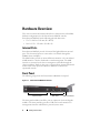 8
8
-
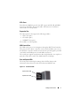 9
9
-
 10
10
-
 11
11
-
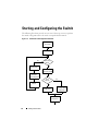 12
12
-
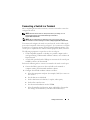 13
13
-
 14
14
-
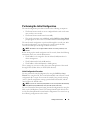 15
15
-
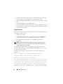 16
16
-
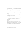 17
17
-
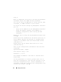 18
18
-
 19
19
-
 20
20
-
 21
21
-
 22
22
-
 23
23
-
 24
24
-
 25
25
-
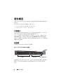 26
26
-
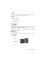 27
27
-
 28
28
-
 29
29
-
 30
30
-
 31
31
-
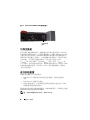 32
32
-
 33
33
-
 34
34
-
 35
35
-
 36
36
-
 37
37
-
 38
38
-
 39
39
-
 40
40
-
 41
41
-
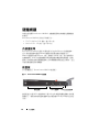 42
42
-
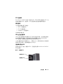 43
43
-
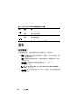 44
44
-
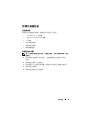 45
45
-
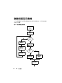 46
46
-
 47
47
-
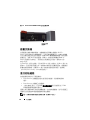 48
48
-
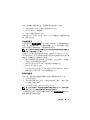 49
49
-
 50
50
-
 51
51
-
 52
52
-
 53
53
-
 54
54
-
 55
55
-
 56
56
-
 57
57
-
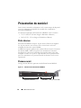 58
58
-
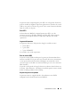 59
59
-
 60
60
-
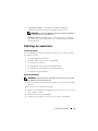 61
61
-
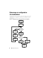 62
62
-
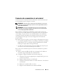 63
63
-
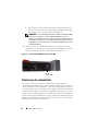 64
64
-
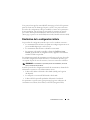 65
65
-
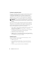 66
66
-
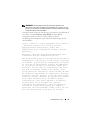 67
67
-
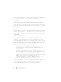 68
68
-
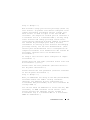 69
69
-
 70
70
-
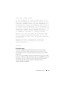 71
71
-
 72
72
-
 73
73
-
 74
74
-
 75
75
-
 76
76
-
 77
77
-
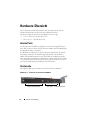 78
78
-
 79
79
-
 80
80
-
 81
81
-
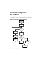 82
82
-
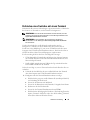 83
83
-
 84
84
-
 85
85
-
 86
86
-
 87
87
-
 88
88
-
 89
89
-
 90
90
-
 91
91
-
 92
92
-
 93
93
-
 94
94
-
 95
95
-
 96
96
-
 97
97
-
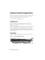 98
98
-
 99
99
-
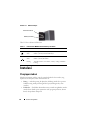 100
100
-
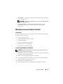 101
101
-
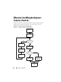 102
102
-
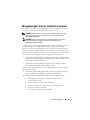 103
103
-
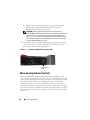 104
104
-
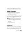 105
105
-
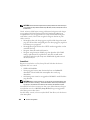 106
106
-
 107
107
-
 108
108
-
 109
109
-
 110
110
-
 111
111
-
 112
112
-
 113
113
-
 114
114
-
 115
115
-
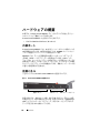 116
116
-
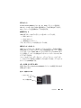 117
117
-
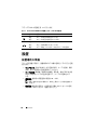 118
118
-
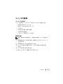 119
119
-
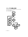 120
120
-
 121
121
-
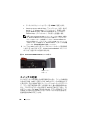 122
122
-
 123
123
-
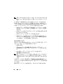 124
124
-
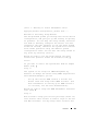 125
125
-
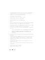 126
126
-
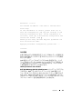 127
127
-
 128
128
-
 129
129
-
 130
130
-
 131
131
-
 132
132
-
 133
133
-
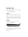 134
134
-
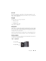 135
135
-
 136
136
-
 137
137
-
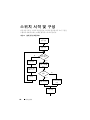 138
138
-
 139
139
-
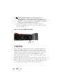 140
140
-
 141
141
-
 142
142
-
 143
143
-
 144
144
-
 145
145
-
 146
146
-
 147
147
-
 148
148
-
 149
149
-
 150
150
-
 151
151
-
 152
152
-
 153
153
-
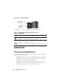 154
154
-
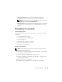 155
155
-
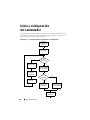 156
156
-
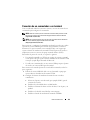 157
157
-
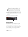 158
158
-
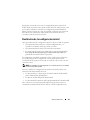 159
159
-
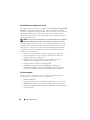 160
160
-
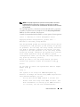 161
161
-
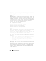 162
162
-
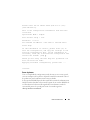 163
163
-
 164
164
-
 165
165
-
 166
166
-
 167
167
-
 168
168
-
 169
169
-
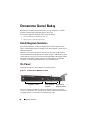 170
170
-
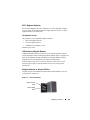 171
171
-
 172
172
-
 173
173
-
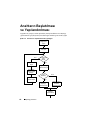 174
174
-
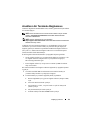 175
175
-
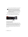 176
176
-
 177
177
-
 178
178
-
 179
179
-
 180
180
-
 181
181
-
 182
182
-
 183
183
-
 184
184
-
 185
185
-
 186
186
-
 187
187
-
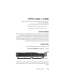 188
188
-
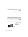 189
189
-
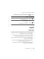 190
190
-
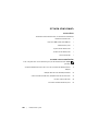 191
191
-
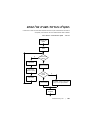 192
192
-
 193
193
-
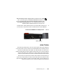 194
194
-
 195
195
-
 196
196
-
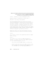 197
197
-
 198
198
-
 199
199
-
 200
200
-
 201
201
-
 202
202
-
 203
203
-
 204
204
-
 205
205
-
 206
206
-
 207
207
-
 208
208
-
 209
209
-
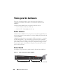 210
210
-
 211
211
-
 212
212
-
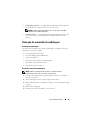 213
213
-
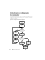 214
214
-
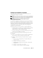 215
215
-
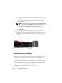 216
216
-
 217
217
-
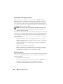 218
218
-
 219
219
-
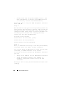 220
220
-
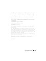 221
221
-
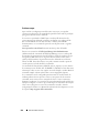 222
222


Dell PowerConnect M8024-K Guía de inicio rápido
- Categoría
- Redes
- Tipo
- Guía de inicio rápido