Yamaha PLG150 El manual del propietario
- Categoría
- Pianos digitales
- Tipo
- El manual del propietario
Este manual también es adecuado para

Piano Plug-in Board
Carte Plug-in piano
Owner’s Manual
Bedienungsanleitung
Mode d’emploi
Piano Plug-in Board

2
PLG150-AP Owner’s Manual
PRECAUTIONS
PLEASE READ CAREFULLY BEFORE PROCEEDING
* Please keep this manual in a safe place for future reference.
WARNING
Always follow the basic precautions listed below to avoid the possibility of serious injury or even death from electrical
shock, short-circuiting, damages, fire or other hazards. These precautions include, but are not limited to, the following:
•When holding the plug-in board, do not touch the inside area of the circuit board
or apply excessive pressure to the board, and be sure to protect the board from
contact with water or other liquids.
• Before installing the plug-in board onto a tone generator/sound card, unplug the
power connector of your computer.
CAUTION
Always follow the basic precautions listed below to avoid the possibility of physical injury to you or others, or damage to
the instrument or other property. These precautions include, but are not limited to, the following:
• Before handling the plug-in board, be sure to touch a metal surface to discharge
any static electricity which may be in your body.
• Before connecting the instrument to other electronic components, turn off the
power for all components. Before turning the power on or off for all components,
set all volume levels to minimum. Also, be sure to set the volumes of all
components at their minimum levels and gradually raise the volume controls
while playing the instrument to set the desired listening level.
• Do not expose the device to excessive dust or vibrations, or extreme cold or heat
(such as in direct sunlight, near a heater, or in a car during the day) to prevent the
possibility of damage to the internal components.
• Do not use the instrument in the vicinity of a TV, radio, stereo equipment, mobile
phone, or other electric devices. Otherwise, the instrument, TV, or radio may
generate noise.
• Do not operate the instrument for a long period of time at a high or uncomfortable
volume level, since this can cause permanent hearing loss. If you experience any
hearing loss or ringing in the ears, consult a physician.
* The company names and product names in this Owner’s Manual are the trademarks or registered trademarks of their respective companies.
* The screens as illustrated in this owner’s manual are for instructional purposes only, and may appear somewhat different from the ones of your instrument.
Yamaha cannot be held responsible for damage caused by improper use or modifications to the device, or data that is lost or destroyed.

3
PLG150-AP Owner’s Manual
Congratulations and thank you for purchasing the Yamaha PLG150-AP Piano Plug-in Board!
The PLG150-AP is a custom tone generator dedicated for piano voices and designed for use
with a variety of Yamaha electronic musical instruments. It provides a wide variety of exception-
ally high-quality, authentic acoustic piano sounds, as well as an assortment of unusual effect-
processed piano sounds. The PLG150-AP can be installed to and integrated with instruments
of the Modular Synthesis Plug-in System (including the S90, MOTIF and MOTIF ES). It can
also be used seamlessly with the MU128 Tone Generator (as well as other MU-series instru-
ments and the SW1000XG PCI Audio/MIDI Board).
To install your PLG150-AP correctly and to ensure full enjoyment of its sophisticated functions,
be sure to read this manual very carefully. When finished, keep the manual in a secure and
convenient place for future reference.
SPECIAL NOTICE
• This product incorporates and bundles computer programs and contents in which Yamaha owns copyrights or with respect to
which it has license to use others’ copyrights. Such copyrighted materials include, without limitation, all computer software, MIDI
files, WAVE data and sound recordings. Any unauthorized use of such programs and contents outside of personal use is not per-
mitted under relevant laws.
• Unauthorized copying of copyrighted software for purposes other than the purchaser’s personal use is prohibited.
About the Modular Synthesis Plug-in System
The Yamaha Modular Synthesis Plug-in System offers powerful expansion and upgrade capa-
bilities for Modular Synthesis-Plug-in-compatible synthesizers, tone generators and sound
cards. This enables you to easily and effectively take advantage of the latest and most sophis-
ticated synthesizer and effects technology, allowing you to keep pace with the rapid and multi-
faceted advances in modern music production.
About the XG Plug-in System
The Yamaha XG Plug-in System offers powerful expansion and upgrade capabilities for XG-
Plug-in-compatible tone generators and sound cards. This enables you to easily and effec-
tively take advantage of the latest and most sophisticated synthesizer and effects technology,
allowing you to keep pace with the rapid and multi-faceted advances in modern music produc-
tion.

4
PLG150-AP Owner’s Manual
Overview of the PLG150-AP....................................................................5
Main Features of the PLG150-AP......................................................................5
Installing the PLG150-AP ..................................................................................5
Included Items ...................................................................................................5
Required and Recommended Items..................................................................6
Specifications.....................................................................................................6
About the Included CD-ROM.............................................................................7
PLG150-AP Structure.............................................................................9
Selecting AP Voices
(Modular Synthesis Plug-in System) ...........................................................10
Editing the AP Native Part Parameters
(Modular Synthesis Plug-in System) ...........................................................11
Selecting/Editing the AP System Parameters
(Modular Synthesis Plug-in System) ...........................................................12
Selecting AP Voices
(XG Plug-in System) ..............................................................................13
Editing the AP Native Part Parameters
(XG Plug-in System) ..............................................................................15
Selecting/Editing the AP System Parameters
(XG Plug-in System) ..............................................................................16
Parameters .........................................................................................17
AP Native Part Parameters .............................................................................17
AP System Parameters ..................................................................................19
Appendix..............................................................................................20
Voice List..............................................................................................................20
Parameter List (XG / Modular Synthesis Plug-in System) ...............................22
MIDI Data Format .................................................................................................23
MIDI Implementation Chart .................................................................................30
Important notice for the SW1000XG users........................................................33
Table of Contents

5
PLG150-AP Owner’s Manual
Overview of the PLG150-AP
● Once connected and installed, the PLG150-AP becomes a seamless additional sound source for the
host tone generator or synthesizer — providing a total of 32 acoustic piano voices, which can be
edited from the panel of the host device. The PLG150-AP can be easily installed to any device
compatible with the Modular Synthesis Plug-in System or the XG Plug-in System.
● A single PLG150-AP Plug-in Board functions as one part for the host device, providing up to 64
different voices (in mono sampling), and several boards can be installed to the same host device.
● Thanks to the built-in effect processing power, the PLG150-AP has four separate effect blocks —
Reverb, Chorus, Insertion and two-band EQ — that can be applied to each voice.
● The PLG150-AP precisely simulates the actual acoustic behavior and motion sound when using the
damper pedal.
● The PLG150-AP features voices with stretch tuning — the same kind of tuning as used on an actual
acoustic piano.
Stretch tuning is widely used in the piano tuning profession, recognizing the phenomenon of human
hearing by which higher notes sound slightly flat, even when perfectly in tune. Stretch tuning pro-
gressively raises the pitch of higher notes and decreases that of lower notes. Compared to precise
equal temperament, the overall effect is greater tonal brilliance and a full, rich sound when playing
open voiced chords.
For detailed instructions on installing the PLG150-AP, refer to the owner’s manual of the Plug-in-
compatible “mother” device (e.g., MOTIF series, S series, MU series, etc.).
The following items have been included in the package of your new PLG150-AP.
Please make sure that you have them all before starting to setup and use the instrument. If an item is
missing, contact the store or dealer from which you purchased the PLG150-AP.
• PLG150-AP Plug-in Board
• PLG150-AP Owner’s Manual (this book)
• CD-ROM
• MSPS sticker
Main Features of the PLG150-AP
Installing the PLG150-AP
Included Items

6
Overview of the PLG150-AP
PLG150-AP Owner’s Manual
In addition to the included items listed above, you should also have the following:
■ Synthesizer/Tone Generator/Sound Card Compatible with the Modular
Synthesis or XG Plug-in Systems
In order to use the PLG150-AP, you’ll need a synthesizer, tone generator or sound card that is com-
patible with the Modular Synthesis Plug-in System or the XG Plug-in System. Compatible instru-
ments include the MOTIF ES, S90, and the MU128. The synthesizer/tone generator/sound card
should also have an available slot or space for installing the PLG150-AP.
Tone Generation System : AWM2 (Advanced Wave Memory 2)
Polyphony : 64 (when using mono-sampled voices)
Number of voices : 32 voices (AP-XG/A, AP-XG/B, Preset)
Interface : Plug-in connector
Effects : Reverb, Chorus, Insertion, 2-Band EQ
Dimensions (W x H x D) : 138.5 x 89.0 x 8.5mm
Weight : 72g
Included Items : Owner’s Manual, CD-ROM, MSPS sticker
* Specifications subject to change without notice.
• Noise may be generated when you assign the “AMod Depth” parameter to the controller and vary the controller
during playback.
Required and Recommended Items
Specifications
NOTE

7
Overview of the PLG150-AP
PLG150-AP Owner’s Manual
The included CD-ROM contains demonstration songs in SMF (Standard MIDI File) format and audio
data, and Plug-in Voice data for MSPS (Modular Synthesis Plug-in System) compatible instruments
to which the PLG150-AP has been installed.
You can play back the audio data from an audio CD player (or a CD drive on your computer.)
Using an A
udio CD Player
Never attempt to play back track 1 on an audio CD player.
Doing so may damage your hearing as well as your CD player/audio speakers.
Track 1: SMF data of the demonstration songs; do NOT attempt to play back this track.
Tracks 2 – 4: Demonstration songs recorded with the PLG150-AP
The included CD-ROM contains the following data.
■ Demonstration Songs
The included CD-ROM contains demo songs that showcase the sounds of the PLG150-AP. The demo
songs are provided in both SMF format and as audio data.
You can play back the SMF data using a sequencer and the audio data from an audio CD player (or a
CD drive on your computer.)
Before Playing Back the Demonstration songs
● For Modular Synthesis Plug-in System Users
Add the Plug-in Voice data to the mother device (page 8), then select the Bank to which the Plug-in
Voices were added (e.g., Plug-in User Voice Bank). In addition, set the MIDI receive channel to “1.”
● For XG Plug-in System Users
Set the Sound Module Mode to “XG”, then set the tone generator to sound the voice of Preset Bank
(MSB = 32, LSB = 1). In addition, set the MIDI receive channel to “1.”
About the Included CD-ROM
CAUTION

8
Overview of the PLG150-AP
PLG150-AP Owner’s Manual
■ Plug-in Voice Data (for Modular Synthesis Plug-in System only)
This is Plug-in voice data, featuring a total of 64 voices that were created using the PLG150-AP Pre-
set voices (Board Voices). A Plug-in Voice is a Board Voice that has been processed using the param-
eters in the synthesizer or tone generator. If you transfer this data via bulk dump to a synthesizer or
tone generator, the Plug-in Voice is added to the User Voice Bank in the Plug-in Bank of the synthe-
sizer or tone generator.
The Plug-in Voice data in the CD-ROM are grouped into the following three folders.
Select the appropriate data in the folder corresponding to your particular synthesizer.
• “S80_CS6X” folder (for CS6x, CS6R, S30, S80)
• “S90MOTIF” folder (for S90, MOTIF, MOTIF-RACK)
• “MOTIF-ES” folder (for MOTIF ES)
How to Add to Plug-in Voice Data to a Synthesizer or Tone Generator
1 Connect a computer to your synthesizer or tone generator using a MIDI or
USB cable.
2 Start up the sequencer software.
3 If the PLG150-AP has been installed to the PLG1 slot, select the file
“**PLGV1.MID”; for slots PLG 2 and PLG 3, select files “**PLGV2.MID” and
“**PLGV3.MID,” respectively. For details, see the owner’s manual for the
sequencer software you are using.
4 The Plug-in Voice data is automatically transferred via bulk dump to the
synthesizer or tone generator.
5 When playback of the data reaches the end and the synthesizer or tone
generator can be operated normally, setup is complete.
• While the synthesizer or tone generator is receiving bulk data, do not turn off the device or sequencer, or dis-
connect the cable.
• The characters represented by “**” above differ depending on the folder.
• Before playing back the Plug-in Voice data, set the synthesizer or tone generator to allow reception of bulk data
(set the “RcvBulk” parameter to on).
NOTE

9
PLG150-AP Owner’s Manual
PLG150-AP Structure
The following illustration shows the structure of PLG150-AP.
For Modular Synthesis Plug-in System Users
• When the Insertion effect of the mother device is bypassed, the Voice Reverb and Voice Chorus of the
PLG150-AP are also bypassed simultaneously. However, when your mother device has an effect bypass
on/off parameter (e.g., “PLG-EF” parameter), set the function to on. If the parameter is off, the effect of
PLG150-AP will not be bypassed.
• The Voice Insertion and Voice EQ of the PLG150-AP cannot be bypassed.
Insertion
Effect
PLG150-AP
Voice
Voice
Voice
Element 8
Element 7
Element 6
Voice
Voice
Chorus
Element 1
Voice
Insertion
Voice
Reverb
PLG150-AP
To change the overall settings for the PLG150-AP, edit the AP
Native System Parameters from the synthesizer or tone genera-
tor to which the PLG150-AP has been installed (page 19).
To change the effect of each Voice, edit the AP Native Part
Parameters from the synthesizer or tone generator to which
the PLG150-AP has been installed (page 17).
Tone Generator of
Plug-in Board block
Synthesizer or Tone Gener-
ator to which the PLG150-
AP has been installed
Insertion Effect bypass is
ON (MSPS-compatible
devices only)
Insertion Effect
bypass is OFF
(MSPS-compatible
devices only)
Voice EQ
(2-Band)
Tone
Generator
Reverb
Chorus
Master Effect
Master EQ
etc.
Insertion Effect bypass is
ON (MSPS-compatible
devices only)
Insertion Effect bypass is
OFF (MSPS-compatible
devices only)
To the synthesizer or tone generator to which
the PLG150-AP has been installed.
Audio Out
NOTE

10
PLG150-AP Owner’s Manual
Selecting AP Voices
(Modular Synthesis Plug-in System)
When the PLG150-AP is installed to a synthesizer compatible with the Modular Synthesis
Plug-in System, the AP voices can be selected in the same way as the internal voices of the
synthesizer.
• The example displays used in the following explanations are all taken from the MOTIF ES.
1 Enter The Voice Play mode.
Press the [VOICE] button.
2 Select a Plug-in Voice bank.
Press one of the [PLG1] – [PLG3] buttons corresponding to the slot to which the PLG150-AP has
been installed.
• The example displays here may differ from the actual ones that appear on your instrument.
3 Select a Group.
Press any of the GROUP [A] – [D] buttons.
4 Select a Voice.
Press any of the NUMBER [1] – [16] buttons.
5 When selecting a bank in PLG150-AP (the MSB/LSB of preset bank (board
voice) or User Voice bank), press the [F2] BANK button, then select a bank.
Next, select a voice following steps 3 and 4 above.
• The bulk-dumped plug-in voice data is saved in the User Voice Bank (PLG1USR).
For a list of the available banks and their MSB/LSB values, refer to the “Voice List” (page 20).
NOTE
NOTE
NOTE

11
PLG150-AP Owner’s Manual
Editing the AP Native Part Parameters
(Modular Synthesis Plug-in System)
The following explanations show how to edit the AP native part parameters when creating Plug-in
Voices, using the MOTIF ES Control Synthesizer as an example. Voices created on the PLG150-AP
are called Board Voices.
On MSPS / XG Plug-in System-compatible devices, you can edit the Board Voices using a variety of
parameter settings, such as effects or EQ (AP native parameters).
On MSPS-compatible devices, the entire Board Voice is edited as one element.
A Board Voice edited on the MSPS-compatible device is called a Plug-in Voice.
For information about how to save Plug-in Voices, refer to the owner’s manual of your MSPS-com-
patible device.
•Keep in mind that the parameter values and settings below represent offsets of the actual voice settings. This
means that adjustments made to the parameters may not make much change in the actual sound, depending
on the original settings of the voice. For parameter values, a setting of “0” results in no change, while positive
and negative values increase and decrease the value respectively.
1 Select the desired AP voice, as described in “Selecting AP Voices” on
page 10.
2 Enter the Voice Edit mode.
Press the [EDIT] button.
3 Select an element to be edited.
1) Press any one of the NUMBER buttons ([1] – [4]) to edit the element parameters.
2) Press the [F4] button to select the “NATIVE” element.
4 Select the desired parameter.
Use the cursor buttons to select the desired parameter.
•For a list of available parameters, see page 17.
5 Adjust the value or change the setting for the selected parameter.
Use the [INC/YES] and [DEC/NO] buttons or the data dial.
NOTE
NOTE

12
PLG150-AP Owner’s Manual
Selecting/Editing the AP System Parameters
(Modular Synthesis Plug-in System)
The parameters that apply to the entire system of the PLG150-AP are called AP native system
parameters (page 19).
The parameters are included in the Utility mode of the MSPS-compatible device to which the
PLG150-AP has been installed.
1 Press the UTILITY button.
The Utility Mode display appears.
2 Press the [F6] (PLUG) button.
3 Press any of the [SF3] – [SF5] (NATIVE1 – NATIVE3) buttons correspond-
ing to the slot to which the PLG150-AP has been installed.
4 Adjust the value or change the setting for the selected parameter.
Use the [INC/YES] and [DEC/NO] buttons or the data dial.

13
PLG150-AP Owner’s Manual
Selecting AP Voices
(XG Plug-in System)
The PLG150-AP voices can be selected just like the voices of the XG tone generator. Keep in mind,
though, that they can only be selected when the Sound Module Mode is set to XG or Performance.
Also, the Part Assign parameter in the Utility mode (see below) must be set to the desired Part.
• The example displays used in the following explanations are all taken from the MU128.
■ Enabling and Selecting AP Voices
1 Set the Sound Module Mode to “XG” or “PFM” (Performance).
Press the [MODE] button and use the [SELECT </>] buttons.
2 Set the Part Assign parameter to the desired Part number.
To do this:
1) Press the [UTIL] button.
2) Select the “PLUGIN” menu (with the [SELECT >] button) and press [ENTER].
3) Select the “PLG150-AP” menu if necessary (with the [SELECT </>] buttons), and press
[ENTER]. The Part Assign menu appears.
4) Use the [VALUE -/+] buttons or dial to change the Part number.
The Part Assign range for the XG mode is 1 – 16 and “off”; for the Performance mode, it is 1 – 4
and “off.”
Press the [EXIT] button to return to the Play mode.
NOTE

14
Selecting AP Voices (XG Plug-in System)
PLG150-AP Owner’s Manual
3 Enable the PLG150-AP board for the desired Part.
First, make sure that the appropriate Part is selected (using the [PART -/+] buttons), then press the
[SELECT] button. The icon of the selected board appears in the display and the corresponding
LED at the bottom of the panel (PLG-1, -2, or -3) flashes briefly.
4 Select the desired bank number.
Move the cursor to the Bank Number parameter with the [SELECT </>] buttons and use the
[VALUE -/+] buttons to select the desired bank.
5 Select the desired voice number.
Move the cursor to the Voice (Program) Number parameter with the [SELECT </>] buttons and
use the [VALUE -/+] buttons to select the desired voice.
•Voice (and Voice banks) can also be selected by using the Voice Category buttons.
• AP-XG/A : 106
• AP-XG/B : 106
• Preset : 001
Alternately, you can select voices from a connected MIDI keyboard, or from sequencing software
on a connected computer.
For a list of available voices and their bank/voice numbers, see page 20.
NOTE
Bank Number parameter
AP-XG/A AP-XG/B Preset

15
PLG150-AP Owner’s Manual
Editing the AP Native Part Parameters
(XG Plug-in System)
Any of the AP voices can be freely edited from the front panel with the AP Native Part parameters.
Keep in mind that changing the Part parameters does not permanently affect the original voice set-
tings. The edits that you make here temporarily change the settings of the currently selected voice.
When you select a different voice for the Part, the settings are applied to the newly selected voice.
• The parameter values and settings below represent offsets of the actual voice settings. This means that
adjustments made to the parameters may not make much change in the actual sound, depending on the origi-
nal settings of the voice. For parameter values, a setting of “0” results in no change, while positive and nega-
tive values increase and decrease the value respectively.
• The Part parameter settings cannot be saved in Multi Play mode. If you wish to save your Part parameter
edits, do it from the Performance mode.
• The example displays used in the following explanations are all taken from the MU128.
1 Select the Part having the AP voice, then select the desired voice.
Select the appropriate Part with the [PART -/+] buttons, then, with the cursor at the Voice Number
parameter, select the desired voice.
2 Press the [EDIT] button to enter the Edit mode.
3 Select the “PLUGIN” menu.
Use the [SELECT >] button, then press the [ENTER] button. The PLG150-AP Edit menu
appears.
4 Select the desired parameter.
Use the [SELECT </>] buttons.
5 Adjust the value or change the setting for the selected parameter.
Use the [VALUE +/-] buttons.
6 Return to the main Play display.
Press the [EXIT] button several times, or press the [PLAY] button once.
NOTE

16
PLG150-AP Owner’s Manual
Selecting/Editing the AP System Parameters
(XG Plug-in System)
The parameters that apply to the entire system of the PLG150-AP are called the AP native system
parameters (page 19).
The parameters are included in the Utility mode menu of the XG tone generator to which the
PLG150-AP has been installed.
• The example displays used in the following explanations are all taken from the MU128.
1 Press the [UTIL] button.
The Utility mode menu appears.
2 Select the “PLUGIN” menu.
Use the [SELECT >] button to highlight “PLUGIN,” then press the [ENTER] button.
3 Select the PLG150-AP board.
If the PLG150-AP board is the only one installed, “PLG150-AP” is already displayed and can be
selected by pressing the [ENTER] button. If additional boards have been installed to the tone
generator, you may need to select “PLG150-AP.” To do this, first use the [SELECT </>] but-
tons, then press [ENTER].
The System parameter menu for the PLG150-AP appears.
4 Select the desired parameter.
Use the [SELECT </>] buttons.
5 Adjust the value or change the setting for the selected parameter.
Use the [VALUE +/-] buttons.
6 Return to the main Play display.
Press the [EXIT] button several times, or press the [PLAY] button once.
NOTE

17
PLG150-AP Owner’s Manual
Parameters
Keep in mind that the parameter values and settings represent offsets of the actual voice settings. This
means that the actual sound that results from the settings made here depends on the original settings
of the voice.
Also keep in mind that these are “Part” parameters and as such, are temporary; they simply alter or
offset the settings of the currently selected voice. The original voice settings are permanently main-
tained in memory.
For parameter values, a setting of “0” results in no change, while positive and negative values increase
and decrease the value respectively.
Let’s look at a specific example. If the original Bass Frequency parameter of the selected voice is set
to 100, and you set the Bass Frequency (below) to “-25,” the actual Bass Frequency will become “75.”
If you set it to “+10,” the value will become “110.” Naturally, this also means that the parameter
value cannot be increased or decreased beyond its maximum or minimum values. In our example,
Bass Frequency values higher than “+27” have no effect on the sound, since the actual range is 0 –
127.
• Depending on the selected voice and the particular parameter being edited, the sound or actual parameter
value of certain voices may change very little or not at all, even when the parameter value is changed drasti-
cally.
•For Modular Synthesis Plug-in System compatible devices, the voices you edit/create can be stored to the
device as PLG voices. For details on storing voices, refer to the owner’s manual of your Modular Synthesis
Plug-in System compatible instrument.
■ PF Mode
Settings: ON, OFF
This determines whether the PF (Piano) Mode is on or off. When this is set to “ON” and damper (sustain) pedal
messages are received, the PLG150-AP simulates the sound of a damper pedal.
If monophonic playback has been selected on your synthesizer, this parameter cannot be set.
■ SusCurve (Sustain Curve)
Settings: Normal, Step (“***”: not available)
This determines how the voices respond to damper (sustain) pedal messages. When this is set to “Normal,” the
PLG150-AP simulates the actual damper pedal action of an acoustic piano, giving you continuous control over sus-
tain. When this is set to “Step,” sustain is simply turned on or off in response to damper pedal messages.
If “PF Mode” (above) has been set to OFF or monophonic playback has been selected on your synthesizer, this
parameter cannot be set.
■ Bass Freq (Bass Frequency)
Range: -64 – +00 – +63
This determines the frequency which is boosted or cut (in the Bass Gain parameter below) for each Part.
■ Bass Gain
Range: -64 – +00 – +63
This determines the level of the selected frequency (in “Bass Freq” above). Positive values boost the level of the
selected frequency and negative values attenuate it.
■ Treble Freq (Treble Frequency)
Range: -64 – +00 – +63
This determines the frequency which is boosted or cut (in the Treble Gain parameter below) for each Part.
AP Native Part Parameters
(PLG150-AP NATIVE MULTI PART (page 29))
NOTE

18
Parameters
PLG150-AP Owner’s Manual
■ Treble Gain
Range: -64 – +00 – +63
This determines the level of the selected frequency (in “Treble Freq” above). Positive values boost the level of the
selected frequency and negative values attenuate it.
■ REV Send (Reverb Send)
Range: -127 – +127 (“****”: not available)
This determines the amount of voice signal that is sent to the PLG150-AP’s built-in Reverb effect.
■ CHO Send (Chorus Send)
Range: -127 – +127 (“****”: not available)
This determines the amount of voice signal that is sent to the PLG150-AP’s built-in Chorus effect.
■ INS LFOFrq (Insertion LFO Frequency)
Range: -127 – +127 (“****”: not available)
This determines the frequency of LFO modulation for the PLG150-AP’s built-in Insertion effect.
■ INS LFODpt (Insertion LFO Depth)
Range: -127 – +127 (“****”: not available)
This determines the depth of LFO modulation for the PLG150-AP’s built-in Insertion effect.
■ INS Feedback (Insertion Feedback Level)
Range: -64 – +63 (“***”: not available)
This determines the feedback level for the PLG150-AP’s built-in Insertion effect.
■ INS DryWet (Insertion Dry/Wet Balance)
Range: -127 – +127 (“****”: not available)
This determines the balance between the direct, unprocessed signal (dry) and the Insertion-processed sound
(wet).
■ INS Offset (Insertion Offset)
Range: -127 – +127 (“****”: not available)
This parameter is used to change one specific parameter of the effect; the particular parameter depends on the
effect type.
■ INS Drive (Insertion Drive)
Range: -127 – +127 (“****”: not available)
This determines the amount of distortion overdrive for the PLG150-AP’s built-in Insertion effect.
■ INS ClpCrv (Insertion Clipping Curve)
Range: -127 – +127 (“****”: not available)
This determines the amount of distortion “edge” for the PLG150-AP’s built-in Insertion effect. Higher values result
in harder edged distortion.
■ INS Delay (Insertion Delay Time)
Range: -7149 – +7149 (“*****”: not available)
This determines the delay time for the PLG150-AP’s built-in Insertion effect.
•Keep in mind that these parameters are offset controls; the actual resulting effect sound will differ
from voice to voice. If the currently selected voice does not have any effect or uses an effect type
not corresponding to this parameter, the parameter is unavailable and is indicated by asterisks
(“***”) in the display.
• Whether this Insertion effect parameter is available or not depends on the selected voice and its pre-
assigned Insertion effect types. (For details on the effect types and parameters for each voice, see
the Preset Voice Bank on page 20.)
NOTE

19
Parameters
PLG150-AP Owner’s Manual
■ Part Assign
Settings: 01 – 16, off
This determines the Part to which the PLG150-AP voice is assigned. If a Part is not properly assigned here, none
of the PLG150-AP voices can be selected for the Part. (This applies to XG Plug-in System compatible “mother”
devices.)
• The PLG150-AP voices can only be assigned to a single Part.
■ VelCurve (Velocity Curve)
Settings: Normal, Soft1, Soft2, Soft3, Hard1, Hard2, Cross1, Cross2
This function lets you set how the volume of the PLG150-AP’s Voices respond to your playing touch (velocity). Eight
different Velocity Curve settings (or curves) are available, letting you tailor the response to your own preference.
● The Normal setting provides standard touch response.
● Soft 1 to 3 allow you to produce a reasonably high volume with a
soft, light touch (low velocities).
● Hard 1 and 2 produce high volume only with a hard, strong touch
(high velocities).
● Cross 1 and 2 are “mirror image” curves, designed to be used
together with different voices in a layer to produce a velocity
crossfade effect. As shown in the illustration, the two curves
complement each other in a way that allows the Cross 2 applied
voice to sound at soft velocities, while the Cross 1 voice sounds
at high velocities.
AP System Parameters
(PLG150-AP NATIVE SYSTEM (page 29))
NOTE

2
PLG150-AP Bedienungsanleitung
VORSICHTSMASSNAHMEN
BITTE SORGFÄLTIG DURCHLESEN, EHE SIE WEITERMACHEN
* Heben Sie diese Anleitung sorgfältig auf, damit Sie später einmal nachschlagen können.
WARNUNG
Befolgen Sie unbedingt die nachfolgend beschriebenen grundlegenden Vorsichtsmaßnahmen, um die Gefahr einer schwer
wiegenden Verletzung oder sogar tödlicher Unfälle, von elektrischen Schlägen, Kurzschlüssen, Beschädigungen, Feuer
oder sonstigen Gefahren zu vermeiden. Zu diesen Vorsichtsmaßnahmen gehören die folgenden Punkte, die jedoch keine
abschließende Aufzählung darstellen:
• Beim Anfassen der Einsteckkarte sollten Sie die Leiterbahnen oder Komponenten
nicht berühren und keinen übermäßigen Druck auf die Karte ausüben. Außerdem
darf die Karte auf keinen Fall mit Wasser oder anderen Flüssigkeiten in Berührung
kommen.
• Ziehen Sie vor der Installation der Einsteckkarte in einem Tongenerator oder einer
Soundkarte den Netzstecker Ihres Computers.
VORSICHT
Befolgen Sie unbedingt die nachfolgend beschriebenen grundlegenden Vorsichtsmaßnahmen, um die Gefahr von
Verletzungen bei Ihnen oder Dritten, sowie Beschädigungen des Instruments oder anderer Gegenstände zu vermeiden.
Zu diesen Vorsichtsmaßnahmen gehören die folgenden Punkte, die jedoch keine abschließende Aufzählung darstellen:
•Vor dem Anfassen der Plug-In-Karte sollten Sie sicherstellen, dass die
elektrostatische Aufladung Ihres Körpers durch Berühren einer geerdeten
Metallfläche abgeleitet wird.
• Ehe Sie das Instrument an andere elektronische Komponenten anschließen,
schalten Sie die Stromversorgung aller Geräte aus. Ehe Sie die Stromversorgung
für alle Komponenten an- oder ausschalten, stellen Sie bitte alle Lautstärkepegel
auf die kleinste Lautstärke ein. Auch immer sicherstellen, dass die Lautstärke aller
Komponenten auf den kleinsten Pegel gestellt werden und die Lautstärke dann
langsam gesteigert wird, während das Instrument gespielt wird, um den
gewünschten Hörpegel einzustellen.
• Setzen Sie das Instrument niemals übermäßigem Staub, Vibrationen oder
extremer Kälte oder Hitze aus (etwa durch direkte Sonneneinstrahlung, die Nähe
einer Heizung oder Lagerung tagsüber in einem geschlossenen Fahrzeug), um die
Möglichkeit auszuschalten, dass sich das Bedienfeld verzieht oder Bauteile im
Innern beschädigt werden.
• Betreiben Sie das Instrument nicht in der Nähe von Fernsehgeräten, Radios,
Stereoanlagen, Mobiltelefonen oder anderen elektrischen Geräten. Anderenfalls
kann durch das Instrument oder die anderen Geräte ein Rauschen entstehen.
• Spielen Sie das Instrument nicht länge Zeit mit hoher oder unangenehmer
Lautstärke, da es hierdurch zu permanentem Gehörverlust kommen kann. Falls
Sie Gehörverlust bemerken oder ein Klingeln im Ohr feststellen, lassen Sie sich
von Ihrem Arzt beraten.
* Die in dieser Bedienungsanleitung erwähnten Firmen- und Produktnamen sind Handelsmarken bzw. eingetragene Handelsmarken der betreffenden Firmen.
* Die in dieser Bedienungsanleitung abgebildeten Displays dienen ausschließlich informativen Zwecken und können daher von den Displays Ihres Instruments
geringfügig abweichen.
Yamaha ist nicht für solche Schäden verantwortlich, die durch falsche Verwendung des Instruments oder durch Veränderungen am Instrument hervorgerufen
wurden, oder wenn Daten verloren gehen oder zerstört werden.

3
PLG150-AP Bedienungsanleitung
Herzlichen Glückwunsch zum Kauf der Klavier-Einsteckkarte Yamaha PLG150-AP, und vielen
Dank für Ihr Vertrauen!
Die PLG150-AP ist ein Spezialtongenerator, der speziell auf Piano-Voices zugeschnitten ist und
mit einer Vielzahl elektronischer Musikinstrumente von Yamaha eingesetzt werden kann. Die
Karte bietet eine große Vielfalt authentischer Klänge eines akustischen Klaviers von
außergewöhnlich hoher Qualität sowie eine Zusammenstellung ungewöhnlicher Klavierklänge
mit Effektverarbeitung. Die PLG150-AP kann in Instrumenten des Modular Synthesis Plug-In
Systems (einschließlich S90, MOTIF und MOTIF ES) installiert und integriert werden. Sie kann
auch nahtlos in den Tongenerator MU128 (sowie andere Instrumente der MU-Serie und die
Audio/MIDI-Karte SW1000XG PCI) integriert werden.
Um die PLG150-AP korrekt installieren und die hoch entwickelten Funktionen in vollem Umfang
verwenden zu können, lesen Sie bitte diese Bedienungsanleitung sorgfältig durch. Bewahren
Sie diese anschließend an einem leicht zugänglichen, sicheren Platz auf, um später wieder
darauf zugreifen zu können.
BESONDERER HINWEIS
• Dieses Produkt enthält und bündelt Computerprogramme und Inhalte, die von Yamaha urheberrechtlich geschützt sind oder für
die Yamaha die Lizenz zur Benutzung der urheberrechtlich geschützten Produkte von Dritten besitzt. Derartige urheberrechtlich
geschützte Materialien umfassen ohne Einschränkung alle Computer-Softwareanwendungen, MIDI-Dateien, WAVE-Daten und
Audioaufnahmen. Jede nicht genehmigte Benutzung von solchen Programmen und Inhalten, die über den persönlichen
Gebrauch hinausgeht, ist nach geltenden Gesetzen nicht gestattet.
• Das Anfertigen von nicht genehmigten Kopien urheberrechtlich geschützter Software zu Zwecken, die nicht dem persönlichen
Gebrauch des Käufers dienen, ist verboten.
Informationen zum Modular Synthesis Plug-In System
Das Modular Synthesis Plug-In System von Yamaha bietet leistungsfähige Erweiterungs- und
Ausbaumöglichkeiten für mit dem Modular Synthesis Plug-In System kompatible Synthesizer,
Tongeneratoren und Soundkarten. Dadurch können Sie einfach und effizient die neuesten
Synthesizer- und Effekttechnologien nutzen und mit dem schnellen und vielfältigen Fortschritt
auf dem Gebiet der Musikproduktion Schritt halten.
Das XG-Plug-In-System
Das XG-Plug-In-System von Yamaha bietet leistungsfähige Erweiterungs- und
Ausbaumöglichkeiten für mit dem XG-Plug-In-System kompatiblen Tongeneratoren und
Soundkarten. Dadurch können Sie einfach und effizient die neuesten Synthesizer- und
Effekttechnologien nutzen und mit dem schnellen und vielfältigen Fortschritt auf dem Gebiet
der Musikproduktion Schritt halten.

4
PLG150-AP Bedienungsanleitung
Übersicht über die PLG150-AP................................................................5
Hauptfunktionen der PLG150-AP ......................................................................5
Installation der PLG150-AP ...............................................................................5
Lieferumfang......................................................................................................5
Erforderliches und empfohlenes Zubehör..........................................................6
Technische Daten..............................................................................................6
Die im Lieferumfang enthaltene CD-ROM.........................................................7
Struktur der PLG150-AP.........................................................................9
Auswahl von AP-Voices
(Modular Synthesis Plug-In System) ...........................................................10
Bearbeiten der AP Native Part Parameter
(Modular Synthesis Plug-In System) ...........................................................11
Auswählen/Bearbeiten der AP-Systemparameter
(Modular Synthesis Plug-In System) ...........................................................12
Auswahl von AP-Voices
(XG-Plug-In-System) ..............................................................................13
Bearbeiten der AP Native Part Parameter
(XG-Plug-In-System) ..............................................................................15
Auswählen/Bearbeiten der AP-Systemparameter
(XG-Plug-In-System) ..............................................................................16
Parameter...........................................................................................17
AP Native Part Parameter ..............................................................................17
AP-Systemparameter ......................................................................................19
Appendix..............................................................................................20
Voice List..............................................................................................................20
Parameter List (XG / Modular Synthesis Plug-In System) ...............................22
MIDI Data Format .................................................................................................23
MIDI Implementation Chart .................................................................................30
Wichtiger Hinweis für Benutzer des SW1000XG...............................................35
Inhalt

5
PLG150-AP Bedienungsanleitung
Übersicht über die PLG150-AP
● Nach Anschluss und Installation wird die PLG150-AP für ihren Host (Tongenerator oder
Synthesizer) zu einer nahtlos integrierten, zusätzlichen Klangquelle mit insgesamt 32 akustischen
Piano-Voices, die auf dem Bedienfeld des Host-Geräts bearbeitet werden können. Die PLG150-AP
kann auf jedem Gerät installiert werden, das kompatibel mit dem Modular Synthesis Plug-In
System oder dem XG Plug-In System ist.
● Eine einzelne Einsteckkarte vom Typ PLG150-AP funktioniert als Teil des Host-Geräts und stellt
bis zu 64 verschiedene Voices (in Mono-Sampling) bereit. Auf einem Host-Gerät können mehrere
Karten installiert werden.
● Dank ihrer eingebauten Effektverarbeitungsmöglichkeiten hat die PLG150-AP vier separate
Effektblöcke - Reverb, Chorus, Insertion und ein Zweiband-EQ - die auf jede Voice angewendet
werden können.
● Die PLG150-AP simuliert exakt das tatsächliche, akustische Verhalten und das
Bewegungsgeräusch, das durch Treten des Dämpfungspedals ausgelöst wird.
● Die PLG150-AP hat Voices mit Stretch-Tuning, dieselbe Art der Stimmung, die auch auf dem
echten, akustischen Klavier verwendet wird.
Das Stretch-Tuning ist unter professionellen Klavierstimmern weit verbreitet, denn es geht auf ein
Phänomen des menschlichen Gehörs ein, das die höheren Noten ein wenig zu tief erscheinen lässt,
selbst wenn sie perfekt gestimmt sind. Mit dem Stretch-Tuning wird die Tonhöhe der höheren Noten
fortschreitend etwas angehoben und die der tieferen Noten leicht gesenkt. Im Vergleich zur präzis
temperierten Stimmung ist der Gesamteindruck von größerer tonaler Brillanz und einem vollen,
reichhaltigen Klang, wenn offene Akkorde einer Voice gespielt werden.
Ausführliche Anweisungen für die Installation der PLG150-AP finden Sie in der
Bedienungsanleitung des steckplatzkompatiblen „Muttergeräts“ (z.B. die MOTIF-Serie, S-Serie,
MU-Serie usw.).
Die folgenden Artikel sind im Lieferumfang des neuen PLG150-AP enthalten.
Vergewissern Sie sich vor der Durchführung des Setups und der Verwendung des Instruments, dass
alle Komponenten vorhanden sind. Wenn ein Artikel fehlt, setzen Sie sich mit dem Geschäft oder dem
Händler in Verbindung, bei dem Sie die PLG150-AP erworben haben.
• Die Einsteckkarte PLG150-AP
• Die Bedienungsanleitung der PLG150-AP (dieses Buch)
• CD-ROM
• MSPS-Aufkleber
Hauptfunktionen der PLG150-AP
Installation der PLG150-AP
Lieferumfang

6
Übersicht über die PLG150-AP
PLG150-AP Bedienungsanleitung
Zusätzlich zu den oben aufgeführten Artikeln benötigen Sie:
■ Synthesizer/Tongenerator/Soundkarte, der/die mit dem
Modular Synthesis- oder XG-Plug-In-System kompatibel ist
Für den Einsatz der PLG150-AP benötigen Sie einen Synthesizer, einen Tongenerator oder eine
Soundkarte, die mit dem Modular Synthesis Plug-In System oder dem XG Plug-In System
kompatibel sind. Kompatible Instrumente sind z.B. MOTIF ES, S90 und MU128. Synthesizer,
Tongenerator oder Soundkarte sollten einen freien Steckplatz zur Installation der PLG150-AP haben.
Klangerzeugungssystem : AWM2 (Advanced Wave Memory 2)
Polyphonie : 64 (bei Verwendung von in Mono gesampelten Voices)
Zahl der Voices : 32 Voices (AP-XG/A, AP-XG/B, Preset)
Schnittstelle : Plug-In-Stecker
Effekte : Reverb, Chorus, Insertion, Zweiband-EQ
Abmessungen (B x H x T) : 138,5 x 89,0 x 8,5 mm
Gewicht : 72 g
Mitgelieferte Artikel : Bedienungsanleitung, CD-ROM, MSPS-Aufkleber.
* Die technischen Daten können ohne vorherige Ankündigung geändert werden.
•Wenn der Parameter „AMod Depth“ dem Controller zugewiesen und während der Wiedergabe der Controller
variiert wird, kann ein Rauschen erzeugt werden.
Erforderliches und empfohlenes Zubehör
Technische Daten
HINWEIS

7
Übersicht über die PLG150-AP
PLG150-AP Bedienungsanleitung
Die mitgelieferte CD-ROM enthält Demo-Songs im SMF-Format (Standard MIDI File) und
Audiodaten, sowie Plug-In-Voicedaten für MSPS-kompatible Instrumente (Modular Synthesis
Plug-In System), in denen die PLG150-AP installiert worden ist.
Sie können die Audiodaten auf einem Audio-CD-Player (oder einem CD-Laufwerk eines Computers)
abspielen.
Bei Verwendung eines Audio-CD-Players
Versuchen Sie nie, Spur 1 auf einem Audio-CD-Player abzuspielen.
Sie können damit Ihr Gehör wie auch den CD-Player oder die Lautsprecher beschädigen.
Spur 1: SMF-Daten der Demo-Songs; versuchen Sie NICHT, diese Spur abzuspielen!
Spuren 2 – 4: Mit der PLG150-AP aufgezeichnete Demo-Songs.
Die mitgelieferte CD-ROM enthält die folgenden Daten.
■ Demo-Songs
Die mitgelieferte CD-ROM enthält Demo-Songs, mit denen die Klänge der PLG150-AP demonstriert
werden. Die Songs liegen im SMF-Format und als Audio-Daten vor.
Sie können die SMF-Daten auf einem Sequenzer und die Audiodaten auf einem Audio-CD-Player
(oder einem CD-Laufwerk eines Computers) abspielen.
Vor dem Abspielen der Demo-Songs
● Für Benutzer des Modular Synthesis Plug-In Systems
Fügen Sie die Plug-In-Voicedaten zum Muttergerät hinzu (Seite 8), und wählen Sie dann die Bank
aus, in der diese Voices gespeichert wurden (z.B. Plug-In User Voice Bank). Außerdem setzen Sie
den MIDI-Empfangskanal auf „1“.
● Für Benutzer des XG Plug-In Systems
Setzen Sie den Sound Module Mode auf „XG“, und stellen Sie den Tongenerator auf die Voice der
Preset Bank ein (MSB = 32, LSB = 1). Außerdem setzen Sie den MIDI-Empfangskanal auf „1“.
Die im Lieferumfang enthaltene CD-ROM
VORSICHT

8
Übersicht über die PLG150-AP
PLG150-AP Bedienungsanleitung
■ Plug-In Voicedaten (nur für Modular Synthesis Plug-In System)
Die Plug-In-Voicedaten enthalten insgesamt 64 Voices, die mit den voreingestellten Voices (Board
Voices) der PLG150-AP erzeugt wurden. Eine Plug-In-Voice ist eine Board-Voice, die im Synthesizer
oder Tongenerator mithilfe der Parameter bearbeitet worden ist. Wenn Sie diese Daten über Bulk-
Dump an einen Synthesizer oder Tongenerator übertragen, wird eine Plug-In-Voice zur User-Voice-
Bank in der Plug-In-Bank des Synthesizers oder Tongenerators hinzugefügt.
Die Plug-In-Voicedaten sind auf der CD-ROM in folgenden drei Ordnern zusammengefasst.
Wählen Sie die gewünschten Daten aus dem Ordner aus, der Ihrem bestimmten Synthesizer
entspricht.
• Ordner „S80_CS6X“ (für CS6x, CS6R, S30, S80)
• Ordner „S90MOTIF“ (für S90, MOTIF, MOTIF-RACK)
• Ordner „MOTIF-ES“ (für MOTIF ES)
So fügen Sie Plug-In-Voicedaten zu einem Synthesizer oder Tongenerator hinzu
1 Schließen Sie einen Computer über MIDI- oder USB-Kabel oder an Ihren
Synthesizer oder Tongenerator an.
2 Starten Sie die Sequenzer-Software.
3 Wenn die PLG150-AP auf dem PLG1-Steckplatz installiert worden ist,
wählen Sie die Datei „**PLGV1.MID“ aus; für die Steckplätze PLG 2 und
PLG 3 wählen Sie „**PLGV2.MID“ bzw „**PLGV3.MID“ aus. Weitere
Informationen finden Sie in der Bedienungsanleitung der von Ihnen
verwendeten Sequenzer-Software.
4 Die Plug-In-Voicedaten werden automatisch über Bulk-Dump an den
Synthesizer oder Tongenerator übertragen.
5 Wenn die Wiedergabe der Daten beendet ist, und der Synthesizer oder
Tongenerator wieder normal bedient werden kann, ist das Setup
vollständig.
• Während der Synthesizer oder Tongenerator Bulk-Daten empfängt, darf das Gerät oder der Sequenzer nicht
ausgeschaltet, noch das Kabel herausgezogen werden.
• Die Platzhalter „**“ in Schritt 3 stehen für den Namen des jeweiligen Ordners.
•Bevor Sie die Plug-In-Voicedaten abspielen, stellen Sie den Synthesizer oder Tongenerator so ein, dass der
Empfang von Bulk-Daten zugelassen ist (setzen Sie den Parameter „RcvBulk“ auf ON).
HINWEIS

9
PLG150-AP Bedienungsanleitung
Struktur der PLG150-AP
In der folgenden Abbildung wird die Struktur der PLG150-AP schematisch dargestellt.
Für Benutzer des Modular Synthesis Plug-In Systems
•Wenn der Insertion-Effekt des Muttergeräts umgangen wird (Bypass = ON), dann werden gleichzeitig auch
die Voices Reverb und Chorus der PLG150-AP umgangen. Falls jedoch das Muttergerät einen Bypass-
Parameter ON/OFF hat (z.B. den Parameter „PLG-EF“), sollte die Funktion eingeschaltet sein. Wenn der
Parameter auf OFF steht, wird der Effekt der PLG150-AP nicht umgangen.
• Die Voices Insertion und EQ der PLG150-AP können nicht umgangen werden.
Insertion
Effect
PLG150-AP
Voice
Voice
Voice
Element 8
Element 7
Element 6
Voice
Voice
Chorus
Element 1
Voice
Insertion
Voice
Reverb
PLG150-AP
Wenn Sie die globalen Einstellungen der PLG150-AP ändern
möchten, bearbeiten Sie die AP-nativen Systemparameter auf
dem Synthesizer oder Tongenerator, in dem die PLG150-AP
installiert worden ist (Seite 19).
Wenn Sie den Effekt einer Voice ändern möchten,
bearbeiten Sie die AP-Native-Systemparameter auf dem
Synthesizer oder Tongenerator, in dem die PLG150-AP
Tongenerator des
Steckkartenblocks
Synthesizer oder
Tongenerator, in dem die
PLG150-AP installiert
worden ist.
Insertion Effect Bypass ist
ON (nur MSPS-
kompatible Geräte)
Insertion Effect
Bypass ist OFF (nur
MSPS-kompatible
Geräte)
Voice EQ
(2-Band)
Ton-
generator
Reverb
Chorus
Master-Effekt
Master-EQ
usw.
Insertion Effect Bypass
ist ON (nur MSPS-
kompatible Geräte)
Insertion Effect Bypass ist
OFF (nur MSPS-
kompatible Geräte)
An den Synthesizer oder Tongenerator, in dem
die PLG150-AP installiert worden ist.
Audio Out
HINWEIS

10
PLG150-AP Bedienungsanleitung
Auswahl von AP-Voices
(Modular Synthesis Plug-In System)
Wenn die PLG150-AP auf einem Synthesizer installiert wird, der mit dem Modular Synthesis
Plug-In System kompatibel ist, dann können die AP-Voices genauso ausgewählt werden wie die
internen Voices des
Synthesizers.
• Die nachfolgend als Beispiele dargestellten Displays stammen alle vom MOTIF ES.
1 Gehen Sie in den Voice-Wiedergabemodus.
Drücken Sie die [VOICE]-Taste.
2 Wählen Sie eine Plug-In Voice Bank aus.
Drücken Sie eine der Tasten [PLG1] – [PLG3], die dem Steckplatz entspricht, in dem die
PLG150-AP installiert ist.
• Die hier abgebildeten Beispieldisplays können sich von denen unterscheiden, die auf Ihrem Instrument
angezeigt werden.
3 Wählen Sie eine Gruppe aus.
Aktivieren Sie eine der GROUP-Schaltflächen [A] - [H].
4 Wählen Sie eine Voice aus.
Drücken Sie eine der NUMBER-Tasten [1] - [16].
5 Wenn Sie eine Bank auf der PLG150-AP auswählen (MSB/LSB der Preset-
Bank (Board-Voice) oder User-Voice-Bank), drücken Sie die Bank-Taste
[F2], und wählen Sie dann eine Bank aus.
Als nächstes wählen Sie eine Voice gemäß Schritt 3 und 4 aus.
• Die als Bulk-Dump übertragenen Plug-In-Voicedaten werden in der User-Voice-Bank (PLG1USR)
gespeichert.
Eine Aufstellung der verfügbaren Banken und ihrer MSB/LSB-Werte erhalten Sie in der „Voice List“
auf Seite 20.
HINWEIS
HINWEIS
HINWEIS

11
PLG150-AP Bedienungsanleitung
Bearbeiten der AP Native Part Parameter
(Modular Synthesis Plug-In System)
Die folgenden Erläuterungen zeigen, wie die AP-Native-Part-Parameter beim Erstellen von Plug-In-
Voices bearbeiten werden. Als Beispiel dient der Control-Synthesizer MOTIF ES. Voices, die auf der
PLG150-AP erstellt worden sind, werden „Board-Voices“ genannt.
Auf Geräten, die kompatibel mit MSPS / XG Plug-In-Systemen sind, können Sie die Board-Voices
über eine Vielzahl von Parametereinstellungen wie Effekte oder EQ bearbeiten. Dies sind die
„nativen“ Parameter, d.h. die lokalen Board-Parameter.
Auf MSPS-kompatiblen Geräten wird die gesamte Board-Voice als ein Element bearbeitet.
Eine Board-Voice, die auf einem MSPS-kompatiblen Gerät bearbeitet wird, heißt „Plug-In-Voice“.
Informationen über das Speichern von Plug-In-Voices finden Sie in der Bedienungsanleitung des
MSPS-kompatiblen Geräts.
• Beachten Sie, dass es sich bei den unten aufgeführten Parameterwerten und Einstellungen nur um
Veränderungswerte (Offsets) für die eigentlichen Voice-Einstellungen handelt. Das bedeutet, dass
Änderungen an den Parametern je nach den ursprünglichen Einstellungen der Voice nur geringe
Auswirkungen auf den tatsächlichen Klang haben können. Für Parameterwerte bewirkt die Einstellung 0
keine Änderung, während positive oder negative Werte den Wert entsprechend erhöhen oder erniedrigen.
1 Wählen Sie die gewünschte AP-Voice aus, wie unter „Auswahl von
AP-Voices“ auf Seite 10 beschrieben.
2 Gehen Sie in den Bearbeitungsmodus für die Voice.
Drücken Sie die [EDIT]-Taste.
3 Wählen Sie das zu bearbeitende Element aus.
1) Drücken Sie eine der [NUMBER]-Tasten [1] - [4], um die Elementparameter zu bearbeiten.
2) Drücken Sie die Taste [F4], um das „NATIVE“-Element auszuwählen.
4 Wählen Sie den gewünschten Parameter aus.
Markieren Sie mithilfe der Cursortasten den gewünschten Parameter.
• Eine Liste der zur Verfügung stehenden Parameter finden Sie auf Seite 17.
5 Ändern Sie den Wert bzw. die Einstellung des ausgewählten Parameters.
Verwenden Sie die Tasten [INC/YES] und [DEC/NO] oder das Datenwählrad.
HINWEIS
HINWEIS

12
PLG150-AP Bedienungsanleitung
Auswählen/Bearbeiten der AP-Systemparameter
(Modular Synthesis Plug-In System)
Parameter, die auf das gesamte System der PLG150-AP angewendet werden können, heißen
„AP-native Systemparameter“ (Seite 19).
Diese Parameter sind im Utility-Modus des MSPS-kompatiblen Geräts, auf dem die PLG150-AP
installiert worden ist, enthalten.
1 Drücken Sie die UTILITY-Taste.
Das Display für den Utility-Modus wird angezeigt.
2 Drücken Sie die Taste [F6] (PLUG).
3 Drücken Sie eine der Tasten [SF3] – [SF5] (NATIVE1 - NATIVE3), die dem
Steckplatz entspricht, in dem die PLG150-AP installiert ist.
4 Ändern Sie den Wert bzw. die Einstellung des ausgewählten Parameters.
Verwenden Sie die Tasten [INC/YES] und [DEC/NO] oder das Datenwählrad.

13
PLG150-AP Bedienungsanleitung
Auswahl von AP-Voices
(XG-Plug-In-System)
Die PLG150-AP-Voices können wie die Voices des XG-Tongenerators ausgewählt werden.
Bedenken Sie jedoch, dass sie nur ausgewählt werden können, wenn der Sound-Module-Modus auf
XG oder Performance eingestellt ist. Außerdem muss der Parameter „Part Assign“ im Utility-Modus
(siehe unten) auf den gewünschten Part eingestellt sein.
• Die in den folgenden Beispielen verwendeten Bildschirmanzeigen stammen alle von der MU128.
■ Aktivieren und Auswählen von AP-Voices
1 Stellen Sie den Sound-Module-Modus auf XG oder Performance ein.
Drücken Sie die Taste [MODE], und verwenden Sie die [SELECT </>]-Tasten.
2 Stellen Sie den Parameter Part Assign auf die gewünschte Part-Nummer
ein.
Tun Sie dazu folgendes:
1) Drücken Sie die Taste [UTIL].
2) Wählen Sie mithilfe der Taste [SELECT>] das Menü „PLUGIN“ aus, und drücken Sie die
Eingabetaste.
3) Wählen Sie, falls erforderlich, mithilfe der Tasten [SELECT </>] das Menü „PLG150-
AP“ aus, und drücken Sie die Eingabetaste. Das Menü „Part Assign“ wird angezeigt.
4) Ändern Sie mit den Tasten [VALUE –/+] oder dem Datenwählrad die Partnummer.
Der Wertebereich für Part Assign im XG-Modus ist 1 - 16 und OFF, und im Performance-Modus
1 -4 und OFF.
Drücken Sie die Taste [EXIT], um in den Play-Modus zurückzukehren.
HINWEIS

14
Auswahl von AP-Voices (XG-Plug-In-System)
PLG150-AP Bedienungsanleitung
3 Aktivieren Sie die Karte PLG150-AP für den gewünschten Part.
Überzeugen Sie sich zunächst davon, dass mithilfe der Tasten [PART –/+] der entsprechende Part
ausgewählt wurde, und klicken Sie dann auf die Taste [SELECT]. Das Symbol des ausgewählten
Boards wird im Display angezeigt, und die entsprechende LED im unteren Bereich des
Bedienfelds (PLG-1, -2 oder -3) leuchtet kurz auf.
4 Wählen Sie die gewünschte Banknummer aus.
Bewegen Sie den Cursor mit den Tasten [SELECT </>] zum Parameter „Bank Number“, und
wählen Sie mithilfe der Tasten [VALUE –/+] die gewünschte Bank aus.
5 Wählen Sie die gewünschte Voice-Nummer aus.
Bewegen Sie den Cursor mit den Tasten [SELECT </>] zum Parameter „Voice (Program)
Number“, und wählen Sie mithilfe der Tasten [VALUE –/+] die gewünschte Voice aus.
•Voices (und Voice-Banken) können auch mit den Schaltflächen [Voice Category] ausgewählt werden.
• AP-XG/A : 106
• AP-XG/B : 106
• Preset : 001
Alternativ können Sie die Voices auch von einem angeschlossenem MIDI-Keyboard oder über die
Sequencer-Software eines angeschlossenen Computers auswählen.
Die Liste der verfügbaren Voices und deren Bank-/Voice-Nummern finden Sie auf Seite 20.
HINWEIS
Banknummern-
Parameter
AP-XG/A AP-XG/B Preset

15
PLG150-AP Bedienungsanleitung
Bearbeiten der AP Native Part Parameter
(XG-Plug-In-System)
Jede der AP-Voices kann über die AP-nativen Part-Parameter des Bedienfelds beliebig bearbeitet
werden. Beachten Sie, dass sich die Änderungen an den Part-Parametern nicht dauerhaft auf die
ursprünglichen Voice-Einstellungen auswirken. Die hier vorgenommenen Änderungen an den
Einstellungen der aktuell ausgewählten Voice haben nur vorübergehend Bestand. Wenn Sie für den
Part eine andere Voice auswählen, werden die Einstellungen auf die neu ausgewählte Voice
angewendet.
• Die unten aufgeführten Parameterwerte und Einstellungen stellen Modifikationen der tatsächlichen Voice-
Einstellungen dar. Das bedeutet, dass Änderungen an den Parametern je nach den ursprünglichen
Einstellungen der Voice nur geringe Auswirkungen auf den tatsächlichen Klang haben können. Für
Parameterwerte bewirkt die Einstellung 0 keine Änderung, während positive oder negative Werte den Wert
entsprechend erhöhen oder erniedrigen.
• Im Multi-Play-Modus können die Parametereinstellungen nicht gespeichert werden. Falls Sie die Änderungen
der Part-Parameter speichern möchten, können Sie dies im Performance-Modus tun.
• Die in den folgenden Beispielen verwendeten Bildschirmanzeigen stammen alle von der MU128.
1 Wählen Sie den Part mit der AP-Voice und anschließend die gewünschte
Voice aus.
Wählen Sie mit den Schaltflächen [PART -/+] den entsprechenden Part, und dann, mit dem
Cursor auf dem Parameter Voice Number, die gewünschte Voice aus.
2 Drücken Sie die Taste [EDIT], um den Bearbeitungsmodus aufzurufen.
3 Wählen Sie das Menü „PLUGIN“ aus.
Verwenden Sie dazu die Taste [SELECT>], und drücken Sie dann die Eingabetaste. Das Menü
„PLG150-AP Edit“ wird angezeigt.
4 Wählen Sie den gewünschten Parameter aus.
Verwenden Sie hierfür die Tasten [SELECT </>].
5 Ändern Sie den Wert bzw. die Einstellung des ausgewählten Parameters.
Verwenden Sie hierfür die Schaltflächen [VALUE +/-].
6 Kehren Sie zum Haupt-Display „Play“ (Wiedergabe) zurück.
Drücken Sie mehrmals die Taste [EXIT] oder einmal die Taste [PLAY].
HINWEIS

16
PLG150-AP Bedienungsanleitung
Auswählen/Bearbeiten der AP-Systemparameter
(XG-Plug-In-System)
Parameter, die auf das gesamte System der PLG150-AP angewendet werden können, heißen
„AP-native Systemparameter“ (Seite 19).
Diese Parameter sind im Utility-Modus-Menü des XG-Tongenerators, auf dem die PLG150-AP
installiert worden ist, enthalten.
• Alle in den folgenden Erklärungen verwendeten Beispiel-Displayanzeigen stammen vom MU128.
1 Drücken Sie die Taste [UTIL].
Das Utility-Modus-Menü wird angezeigt.
2 Wählen Sie das Untermenü „PLUGIN“ aus.
Markieren Sie mithilfe der Taste [SELECT >] die Option „PLUGIN“, und drücken Sie dann die
Eingabetaste [ENTER].
3 Wählen Sie die Karte PLG150-AP aus.
Ist die PLG150-AP die einzige installierte Einsteckkarte, so ist „PLG150-AP“ bereits markiert
und kann durch Drücken der Eingabetaste ausgewählt werden. Wenn weitere Karten im
Tongenerator installiert worden sind, müssen Sie zunächst den Eintrag „PLG150-AP“ markieren.
Verwenden Sie dazu die Schaltflächen SELECT</>, und drücken Sie dann die Eingabetaste.
Das Systemparameter-Menü der PLG150-AP wird angezeigt.
4 Wählen Sie den gewünschten Parameter aus.
Verwenden Sie dazu die Tasten [SELECT </>].
5 Ändern Sie den Wert bzw. die Einstellung des ausgewählten Parameters.
Verwenden Sie hierfür die Schaltflächen [VALUE +/-].
6 Kehren Sie zum Haupt-Display „Play“ (Wiedergabe) zurück.
Drücken Sie mehrmals die Taste [EXIT] oder einmal die Taste [PLAY].
HINWEIS

17
PLG150-AP Bedienungsanleitung
Parameter
Bedenken Sie, dass es sich bei den Parameterwerten und Einstellungen nur um Veränderungswerte
(Offsets) für die eigentlichen Voice-Einstellungen handelt. Das bedeutet, dass der tatsächliche Klang,
den die hier vorgenommenen Einstellungen hervorbringen, von den ursprünglichen Voice-
Einstellungen abhängt.
Beachten Sie auch, dass es sich hierbei um Part-Parameter handelt, die nur vorübergehend wirksam
sind. Sie ändern oder verschieben lediglich die Einstellungen der gegenwärtig ausgewählte Voice.
Die ursprünglichen Voice-Einstellungen bleiben dauerhaft im Speicher gespeichert.
Für Parameterwerte bewirkt die Einstellung 0 keine Änderung, während positive oder negative Werte
den Wert entsprechend erhöhen oder erniedrigen.
Hier ist ein konkretes Beispiel: Ist der ursprüngliche Bassfrequenz-Parameter der ausgewählten Voice
auf 100 eingestellt, und Sie setzen die Bassfrequenz (siehe unten) auf -25, dann wird die aktuelle
Bassfrequenz bei 75 liegen. Stellen Sie den Parameter auf +10 ein, erhöht sich der Wert auf 110.
Natürlich bedeutet das auch, dass der Parameterwert nicht jenseits seiner Maximal- bzw.
Minimalwerte verstellt werden kann. In unserem Beispiel haben Bassfrequenzwerte über +27 keinen
Einfluss auf den Klang, da die Skala nur von 0 bis 127 reicht.
• Abhängig von der gewählten Voice und dem gerade bearbeiteten Parameter können sich der Klang oder der
tatsächliche Parameterwert bestimmter Voices nur sehr geringfügig oder überhaupt nicht ändern, selbst wenn
Sie den Parameterwert drastisch ändern.
• Bei MSPS-kompatiblen Geräten können die von bearbeiteten oder neu erstellten Voices auf dem Gerät als
PLG-Voices gespeichert werden. Einzelheiten über das Speichern von Voices finden Sie in der
Bedienungsanleitung des Instruments, das mit dem Modular Synthesis Plug-In System kompatibel ist.
■ PF Mode
Einstellungen:ON, OFF
Hiermit wird festgelegt, ob der Klavier-Modus ein- oder ausgeschaltet ist. Wenn der Parameter eingeschaltet ist
(ON), und es werden Signale vom Dämpferpedal (Haltepedal) empfangen, dann simuliert die PLG150-AP den
Klang mit Dämpferpedal.
Ist auf dem Synthesizer die Mono-Wiedergabe ausgewählt, kann dieser Parameter nicht eingestellt werden.
■ SusCurve (Sustain Curve, Ausklingkurve)
Einstellungen: Normal, Step („***“: nicht verfügbar)
Diese Einstellung steuert die Reaktion der Voices auf Signale des Dämpferpedals (Haltepedals). Bei der
Einstellung „Normal“ simuliert die PLG150-AP die Dämferpedal-Aktionen eines akustischen Klaviers, so dass Sie
die ständige Kontrolle über die Ausklingfunktion besitzen. Bei der Einstellung „Step“ wird die Ausklingfunktion
durch die Signale des Dämpferpedals einfach ein- oder ausgeschaltet.
Wenn „PF Mode“ (siehe oben) ausgeschaltet (OFF) oder die Mono-Wiedergabe auf dem Synthesizer ausgewählt
ist, kann dieser Parameter nicht eingestellt werden.
■ Bass Freq (Bass Frequency, Bassfrequenz)
Einstellbereich: -64 – +00 – +63
Diese Einstellung bestimmt, welche der Frequenzen der einzelnen Parts angehoben bzw. abgesenkt werden (siehe
„Bass Gain“ weiter unten).
■ Bass Gain (Bassverstärkung)
Einstellbereich: -64 – +00 – +63
Diese Einstellung bestimmt den Pegel der ausgewählten Frequenz (siehe „Bass Freq“ weiter oben). Positive Werte
heben den Pegel der ausgewählten Frequenz an, negative Werte senken ihn.
■ Treble Freq (Treble Frequency, Höhenfrequenz)
Einstellbereich: -64 – +00 – +63
Diese Einstellung legt die Frequenz fest, die angehoben bzw. abgesenkt wird (siehe „Treble Gain“ unten).
AP Native Part Parameter
(PLG150-AP NATIVE MULTI PART (Seite 29))
HINWEIS

18
Parameter
PLG150-AP Bedienungsanleitung
■ Treble Gain (Höhenverstärkung)
Einstellbereich: -64 – +00 – +63
Diese Einstellung bestimmt den Pegel der in „Treble Freq“ (siehe oben) ausgewählten Frequenz. Positive Werte
heben den Pegel der ausgewählten Frequenz an, negative Werte senken ihn.
■ REV Send (Reverb Send, an Hall-Effekt senden)
Einstellbereich: -127 — +127 („****“ nicht verfügbar)
Diese Einstellung legt die Stärke des Voice-Signals fest, das an den in der PLG150-AP integrierten Hall-Effekt
gesendet wird.
■ CHO Send (Chorus Send, an Chorus-Effekt senden)
Einstellbereich: -127 — +127 („****“ nicht verfügbar)
Diese Einstellung legt die Stärke des Voice-Signals fest, das an den in der PLG150-AP integrierten Chorus-Effekt
gesendet wird.
■ INS LFOFrq (Insertion LFO Frequency)
Einstellbereich: -127 — +127 („****“ nicht verfügbar)
Diese Einstellung legt die Frequenz der LFO-Modulation für den in der PLG150-AP integrierten Insertion-Effekt fest.
■ INS LFODpt (Insertion LFO Depth)
Einstellbereich: -127 — +127 („****“ nicht verfügbar)
Diese Einstellung legt die Tiefe der LFO-Modulation für den in der PLG150-AP integrierten Insertion-Effekt fest.
■ INS Feedback (Insertion Feedback Level)
Einstellbereich: -64 — +63 („****“ nicht verfügbar)
Diese Einstellung legt den Feedbackpegel für den in der PLG150-AP integrierten Insertion-Effekt fest.
■ INS DryWet (Insertion Dry/Wet Balance)
Einstellbereich: -127 — +127 („****“ nicht verfügbar)
Diese Einstellung legt das Verhältnis zwischen dem direkten unmodulierten Signal (Dry) und dem durch den
Insertion-Effekt veränderten Klang (Wet) fest.
■ INS Offset (Insertion Offset)
Einstellbereich: -127 — +127 („****“ nicht verfügbar)
Mit diesem Parameter wird nur ein bestimmter Parameter des Insertion-Effekts geändert. Der entsprechende
Parameter hängt vom Effekttyp ab.
■ INS Drive (Insertion Drive)
Einstellbereich: -127 — +127 („****“ nicht verfügbar)
Diese Einstellung bestimmt das Maß der Verzerrung (Distortion Overdrive) des in der PLG150-AP integrierten
Insertion-Effekts.
■ INS ClpCrv (Insertion Clipping Curve, Insertion-Begrenzungskurve)
Einstellbereich: -127 — +127 („****“ nicht verfügbar)
Diese Einstellung bestimmt das Maß der „Verzerrungskante“ des in der PLG150-AP integrierten Insertion-Effekts.
Höhere Werte ergeben eine stärkere Verzerrung (d.h. mit härterer Kante).
■ INS Delay (Insertion Delay Time, Verzögerungszeit)
Einstellbereich: -7149 — +7149 („****“ nicht verfügbar)
Diese Einstellung bestimmt die Verzögerungszeit des in der PLG150-AP integrierten Insertion-Effekts.
• Beachten Sie, dass diese Parameter Offset-Steuerungen sind, die unterschiedliche Auswirkungen
auf die verschiedenen Voices hervorrufen. Weist die aktuell ausgewählte Voice keinen Effekt auf,
oder benutzt sie einen Effekttyp, der nicht mit diesem Parameter korrespondiert, dann ist der
Parameter nicht verfügbar und in der Anzeige mit „***“ gekennzeichnet.
• Ob der Parameter des Insertion-Effekts verfügbar ist, hängt von der ausgewählten Voice und dem
ihr vorher zugewiesenen Insertion-Effekttyp ab. (Einzelheiten über die Effekttypen und Parameter
für jede Voice finden Sie unter „Preset Voice Bank“ auf Seite 20.)
HINWEIS

19
Parameter
PLG150-AP Bedienungsanleitung
■ Part Assign (Part zuordnen)
Einstellungen: 01 — 16, OFF
Diese Einstellung legt den Part fest, dem die Voice der PLG150-AP zugewiesen wird. Unterbleibt an dieser Stelle
die ordnungsgemäße Zuweisung zu einem Part, so kann keine der Voices der PLG150-AP für den Part ausgewählt
werden. (Dies bezieht sich auf die mit dem XG-Plug-In-System kompatiblen "Muttergeräte“.)
• Die Voices der PLG150-AP können nur einem einzigen Part zugewiesen werden.
■ VelCurve (Velocity Curve, Lautstärkenkurve)
Einstellungen: Normal, Soft1, Soft2, Soft3, Hard1, Hard2, Cross1, Cross2
Diese Funktion erlaubt die Festlegung, in welchem Maß sich die Anschlagstärke (Velocity) auf die Lautstärke der
Voices der PLG150-AP auswirkt. Die acht verfügbaren Einstellungen der Lautstärkenkurve(n) ermöglichen eine
Lautstärkenregelung entsprechend Ihren persönlichen Präferenzen.
● Die Normal-Einstellung liefert die Standardlautstärke bei
durchschnittlichem Anschlag.
● Die Soft1- bis Soft3-Einstellung erzielt eine hohe Lautstärke
bei weichem Anschlag.
● Die Hard1- und Hard2-Einstellung erzielt nur eine hohe
Lautstärke bei hartem Anschlag.
● Die Einstellungen Cross1 und Cross2 sind für den
gemeinsamen Einsatz mit verschiedenen Voices in einem Layer
konzipiert, um einen Lautstärke-Überblendeffekt (Velocity
Crossfade) zu erzeugen. Wie in der Abbildung gezeigt, ergänzen
sich die beiden Kurven derart, dass die Voice mit Cross 2 bei
weichem Anschlag erklingt, während die Voice mit Cross 1 bei
hartem Anschlag ertönt.
AP-Systemparameter
(PLG150-AP NATIVE SYSTEM (Seite 29))
HINWEIS

2
PLG150-AP Mode d'emploi
PRECAUTIONS
PRIERE DE LIRE ATTENTIVEMENT AVANT DE PROCEDER
* Rangez soigneusement ce manuel pour pouvoir le consulter ultérieurement.
AVERTISSEMENT
Veillez à toujours observer les précautions élémentaires énumérées ci-après pour éviter de graves blessures, voire la
mort, causées par l'électrocution, les courts-circuits, dégâts, incendie et autres accidents. La liste des précautions
données ci-dessous n'est pas exhaustive :
• Lorsque vous tenez la carte plug-in, ne touchez pas la partie interne de la carte de
circuit imprimé, n'exercez pas de pression excessive sur la carte et ne la mettez
pas en contact avec de l'eau ou tout autre liquide.
•Avant d'installer la carte plug-in sur un générateur de sons ou une carte son,
débranchez la prise électrique de votre ordinateur.
ATTENTION
Veillez à toujours observer les précautions élémentaires ci-dessous pour éviter à soi-même et à son entourage des
blessures corporelles, de détériorer l'instrument ou le matériel avoisinant. La liste de ces précautions n'est pas
exhaustive :
•Avant de manipuler la carte plug-in, touchez une surface en métal pour vous
décharger de toute l'électricité statique susceptible de se trouver dans votre corps.
•Avant de raccorder l'instrument à d'autres éléments électroniques, mettez ces
derniers hors tension. Et avant de mettre sous/hors tension tous les éléments,
veillez à toujours ramener le volume au minimum. En outre, veillez à régler le
volume de tous les composants au minimum et à augmenter progressivement le
volume sonore des instruments pour définir le niveau d'écoute désiré.
• N’abandonnez pas l'instrument dans un milieu trop poussiéreux ou un local
soumis à des vibrations. Evitez également les froids et chaleurs extrêmes
(exposition directe au soleil, près d'un chauffage ou dans une voiture exposée
en plein soleil) qui risquent de déformer le panneau ou d'endommager les
éléments internes.
• N’utilisez pas l'instrument à proximité d'une TV, d'une radio, d'un équipement
stéréo, d'un téléphone portable ou d'autres appareils électriques. En effet,
l'instrument, la TV ou la radio pourraient produire des interférences.
• Ne jouez pas trop longtemps sur l'instrument à des volumes trop élevés, ce qui
risque d'endommager durablement l'ouïe. Si vous constatez une baisse de l'acuité
auditive ou des sifflements d'oreille, consultez un médecin sans tarder.
* Les noms de sociétés et de produits cités dans ce mode d'emploi sont des marques commerciales ou des marques déposées appartenant à leurs détenteurs
respectifs.
* Les écrans représentés dans ce mode d'emploi sont donnés à titre d'information. Ils peuvent par conséquent être différents de ceux apparaissant sur votre
instrument
Yamaha n'est pas responsable des détériorations causées par une utilisation impropre de l'instrument ou par des modifications apportées par l'utilisateur, pas plus
qu'il ne peut couvrir les données perdues ou détruites.

3
PLG150-AP Mode d'emploi
Félicitations ! Nous vous remercions d'avoir acheté la carte plug-in piano Yamaha PLG150-AP !
La carte PLG150-AP est un générateur de son personnalisé, spécifiquement destiné aux voix
de piano et conçu pour être utilisé avec divers instruments musicaux électroniques Yamaha.
Elle offre une grande variété de sonorités de piano acoustique authentiques, d'une qualité
exceptionnelle, ainsi qu'une palette de sons de piano traités par des effets inédits. La carte
PLG150-AP peut être installée sur ou intégrée à d'autres instruments du Modular Synthesis
Plug-in System (dont le S90, le MOTIF et le MOTIF ES). Elle fonctionne également en parfaite
transparence avec le générateur de sons MU128 et d'autres instruments de la série MU, ainsi
qu'avec la carte SW1000XG PCI Audio/MIDI.
Pour installer correctement votre carte PLG150-AP et exploiter au mieux toutes les fonctions
élaborées qu'elle offre, lisez attentivement ce mode d'emploi. Lorsque vous en avez terminé la
lecture, conservez-le dans un endroit sûr et à portée de main pour le consulter ultérieurement si
nécessaire.
REMARQUE SPECIALE
• Ce produit comporte et met en œuvre des programmes informatiques et des contenus pour lesquels Yamaha détient des droits
d'auteur ou possède une licence d'utilisation des droits d'auteurs des propriétaires respectifs. Les matériaux sujets à des droits
d'auteur comprennent, sans limitation, tous les logiciels, les fichiers MIDI, les données WAVE et les enregistrements sonores.
Toute utilisation non autorisée de ces programmes et de leur contenu est interdite en vertu des lois en vigueur, excepté pour un
usage personnel.
•Toute copie non autorisée du logiciel protégé par copyright à des fins autres que l'utilisation personnelle par l'acheteur est
interdite.
A propos du Modular Synthesis Plug-in System
Le Modular Synthesis Plug-in System de Yamaha offre de puissantes fonctions d'expansion et
de mise à niveau pour synthétiseurs, générateurs de son et cartes son compatibles. Ceci vous
permet de tirer facilement et efficacement parti des dernières avancées technologiques les plus
élaborées en matière de synthèse et d'effets, et de suivre de près l'évolution rapide et variée de
la production musicale moderne.
A propos du XG Plug-in System
Le XG Plug-in System de Yamaha offre aux générateurs de son et cartes son compatibles avec
le système plug-in XG de puissantes possibilités d'expansion et de mise à niveau. Ceci vous
permet de tirer facilement et efficacement parti des dernières avancées technologiques les plus
élaborées en matière de synthèse et d'effets, et de suivre de près l'évolution rapide et variée de
la production musicale moderne.

4
PLG150-AP Mode d'emploi
Présentation de la carte PLG150-AP.......................................................5
Fonctions principales de la carte PLG150-AP...................................................5
Installation de la carte PLG150-AP....................................................................5
Eléments inclus..................................................................................................5
Matériel nécessaire et recommandé..................................................................6
Spécifications.....................................................................................................6
A propos du CD-ROM fourni..............................................................................7
Structure de la carte PLG150-AP............................................................9
Sélection des voix AP
(Modular Synthesis Plug-in System) ...........................................................10
Edition des paramètres des parties natives AP
(Modular Synthesis Plug-in System) ...........................................................11
Sélection/Edition des paramètres du système AP
(Modular Synthesis Plug-in System) ...........................................................12
Sélection des voix AP
(XG Plug-in System) ..............................................................................13
Edition des paramètres des parties natives AP
(XG Plug-in System) ..............................................................................15
Sélection/Edition des paramètres de système AP
(XG Plug-in System) ..............................................................................16
Paramètres .........................................................................................17
Paramètres des parties natives AP .................................................................17
Paramètres système AP .................................................................................19
Appendix..............................................................................................20
Voice List..............................................................................................................20
Parameter List (XG / Modular Synthesis Plug-in System) ...............................22
MIDI Data Format .................................................................................................23
MIDI Implementation Chart .................................................................................30
Avis important pour les utilisateurs de la carte SW1000XG............................37
Sommaire

5
PLG150-AP Mode d'emploi
Présentation de la carte PLG150-AP
● Une fois connectée et installée, la carte PLG150-AP représente une nouvelle source de son,
directement utilisable par le générateur de son hôte ou le synthétiseur, et qui propose jusqu'à
32 voix de piano acoustique, modifiables à l'aide du panneau de l'instrument hôte. La carte
PLG150-AP s'installe facilement sur tout dispositif compatible avec le Modular Synthesis Plug-in
System ou le XG Plug-in System.
● Une carte plug-in PLG150-AP unique sert de partie pour le dispositif hôte, fournissant jusqu'à
64 voix différentes (en échantillonnage mono), mais vous pouvez installer plusieurs cartes sur le
même appareil hôte.
● Grâce à la puissante fonction de traitement d'effets intégrée, la carte PLG150-AP dispose de quatre
blocs d'effets distincts, applicables à chaque voix : Reverb, Chorus, Insertion et EQ à deux bandes.
● La carte PLG150-AP simule avec précision le comportement acoustique réel et le mouvement du
son opérés par la pédale forte.
● La carte PLG150-AP dispose de voix caractérisées par une tonalité étirée, semblable à celle que
l'on entend sur les véritables pianos acoustiques.
La tonalité étirée ou rallongée est communément utilisée par les professionnels, qui exploitent le
phénomène auditif selon lequel les notes les plus hautes retentissent légèrement comme avec un
bémol, même lorsqu'elles sont parfaitement dans la tonalité souhaitée. Cela augmente
progressivement la hauteur de ton des plus hautes notes et diminue celle des notes les plus basses.
Comparé à une gamme classique ou normale, l'effet d'ensemble induit est celui d'une tonalité plus
vive et un son riche et plein qui interviennent sur des accords ouverts.
Pour les instructions d'installation détaillées de la carte PLG150-AP, reportez-vous au mode d'emploi
du dispositif compatible plug-in principal sur lequel vous souhaitez l'installer (par ex., série MOTIF,
série S, série MU, etc.).
Les éléments suivants sont livrés avec votre nouvelle carte PLG150- AP.
Veuillez vérifier qu'aucun d'eux ne manque avant de commencer à configurer et à utiliser l'instrument.
S'il vous manque un article, contactez le magasin ou le revendeur auprès duquel vous avez acheté la
carte PLG150-AP.
• Carte plug-in PLG150-AP
• Mode d'emploi de la carte PLG150-AP (ce manuel)
• CD-ROM
• Autocollant MSPS
Fonctions principales de la carte PLG150-AP
Installation de la carte PLG150-AP
Eléments inclus

6
Présentation de la carte PLG150-AP
PLG150-AP Mode d'emploi
Outre les articles énumérés ci-dessus, vous devez également disposer des éléments suivants :
■ Synthétiseur/générateur de son/carte son compatible avec les
Modular Synthesis ou XG Plug-in Systems
Pour utiliser la carte PLG150-AP, il faut disposer d'un synthétiseur, d'un générateur de son ou d'une
carte son compatible avec le Modular Synthesis Plug-in System ou le XG Plug-in System. Parmi les
instruments compatibles figurent le MOTIF ES, le S90 et le MUI28. Le synthétiseur, le générateur de
son et la carte son doivent être dotés d'un connecteur ou d'un emplacement prévu pour l'installation de
la carte PLG150-AP.
Système de générateur de sons : AWM2 (Advanced Wave Memory 2)
Polyphonie : 64 (lors de l'utilisation de voix échantillonnées en mono)
Nombre de voix : 32 voix (AP-XG/A, AP-XG/B, Présélections)
Interface : Connecteur plug-in
Effets : Reverb, Chorus, Insertion, EQ 2 bandes
Dimensions (L x H x P) : 138,5 x 89,0 x 8,5 mm
Poids : 72 g
Vous sont fournis avec la carte : un mode d'emploi, un CD-ROM, un autocollant MSPS
* Ces spécifications peuvent faire l'objet de modifications sans préavis.
• Du bruit peut être généré lorsque vous affectez le paramètre « AMod Depth » au contrôleur et que vous
modifiez le contrôleur durant la reproduction.
Matériel nécessaire et recommandé
Spécifications
NOTE

7
Présentation de la carte PLG150-AP
PLG150-AP Mode d'emploi
Le CD-ROM fourni contient des morceaux de démonstration au format SMF (fichier MIDI standard),
sous forme de données audio et des données de voix plug-in pour les instruments compatibles avec le
système MSPS (Modular Synthesis Plug-in System) sur lesquels la carte PLG150-AP a été installée.
Vous pouvez reproduire les données audio depuis un lecteur de CD audio (ou à l'aide d'une fonction
de lecture de CD sur votre ordinateur).
Si vous utilisez un lecteur CD traditionnel
N'essayez jamais de lire le CD-ROM sur un lecteur de CD audio.
Cela pourrait endommager votre ouïe, ainsi que le lecteur de CD et les haut-parleurs.
Piste 1 : données SMF de morceaux de démonstration ; n'essayez PAS de reproduire cette piste.
Pistes 2 à 4 : morceaux de démonstration enregistrés sur la carte PLG150-AP.
Le CD-ROM fourni contient les données suivantes :
■ Morceaux de démonstration
Le CD-ROM fourni contient des morceaux de démonstration qui présentent les sonorités de la carte
PLG150-AP. Les morceaux de démonstration sont fournis à la fois en format SMF et en format de
données audio.
Vous pouvez reproduire les données SMF à l'aide d'un séquenceur et les données audio depuis un
lecteur de CD audio (ou à l'aide d'une fonction de lecture de CD sur votre ordinateur).
Avant de reproduire les morceaux de démonstration
● A l'attention des utilisateurs du Modular Synthesis Plug-in System
Ajoutez les données de voix plug-in au dispositif mère (page 8), puis sélectionnez la banque dans
laquelle les voix plug-in ont été ajoutées (par ex., la banque de voix utilisateur plug-in). En outre,
réglez le canal de réception MIDI sur « 1 ».
● A l'attention des utilisateurs du XG Plug-in System
Spécifiez le mode Sound Module (Module son) sur « XG », puis réglez le générateur de son afin de
faire retentir la voix de la banque présélectionnée (MSB = 32, LSB = 1). En outre, réglez le canal de
réception MIDI sur « 1 ».
A propos du CD-ROM fourni
ATTENTION

8
Présentation de la carte PLG150-AP
PLG150-AP Mode d'emploi
■ Données de voix plug-in (uniquement pour Modular Synthesis
Plug-in System)
Il s'agit des données de voix plug-in, constituant au total 64 voix créées à l'aide des voix
présélectionnées (voix sur carte) de la carte PLG150-AP. Une voix plug-in est une voix enregistrée sur
carte, qui a été traitée à l'aide des paramètres du synthétiseur ou du générateur de son. Si vous
transférez ces données en bloc vers le synthétiseur ou le générateur de son, la voix plug-in sera
ajoutée à la voix de la banque utilisateur dans la banque plug-in du synthétiseur ou du générateur de
son.
Les données de voix plug-in dans le CD-ROM sont regroupées dans les trois dossiers suivants.
Sélectionnez les données appropriées dans le dossier correspondant à votre synthétiseur spécifique.
• Dossier « S80_CS6X » (pour CS6x, CS6R, S30, S80)
• Dossier « S90MOTIF » (pour S90, MOTIF, MOTIF-RACK)
• Dossier « MOTIF-ES » (pour MOTIF ES)
Comment ajouter des données de voix plug-in à un synthétiseur ou un générateur de son
1 Connectez un ordinateur à votre synthétiseur ou générateur de son,
à l'aide d'un câble MIDI ou USB.
2 Démarrez le logiciel séquenceur.
3 Si la carte PLG150-AP a été installée dans le connecteur PLG1,
sélectionnez le fichier « **PLGV1.MID » ; pour les connecteurs PLG 2 et
PLG 3, sélectionnez respectivement les fichiers « **PLGV2.MID » et
« **PLGV3.MID ». Pour plus de détails, lisez attentivement le mode
d'emploi du logiciel séquenceur que vous utilisez.
4 Les données de voix plug-in sont automatiquement transférées en bloc
vers le synthétiseur ou le générateur de son.
5 Lorsque la reproduction de ces données touche à sa fin, et que le
synthétiseur ou le générateur de son peuvent être opérés normalement, la
configuration est terminée.
•Pendant que le synthétiseur ou le générateur de son reçoivent des données en bloc, ne mettez pas le
dispositif ou le séquenceur hors tension et ne déconnectez pas le câble.
• Les caractères représentés par « ** » ci-dessus varient selon le dossier.
•Avant de reproduire les données de voix plug-in, réglez le synthétiseur ou le générateur de son de sorte
à recevoir l'envoi de données en bloc (activez le paramètre « RcvBulk » (Réception en bloc)).
NOTE

9
PLG150-AP Mode d'emploi
Structure de la carte PLG150-AP
L'illustration suivante montre la structure de la carte PLG150-AP.
A l'attention des utilisateurs du Modular Synthesis Plug-in System
• Lorsque l'effet d'insertion du dispositif mère est contourné, les effets Voice Reverb (Réverbération de voix)
et Voice Chorus (Chœur de voix) de la carte PLG150-AP sont aussi simultanément ignorés. Cependant,
lorsque le dispositif mère est doté d'un paramètre d'activation/désactivation du contournement d'effet
(par ex. le paramètre « PLG-EF »), il faut activer cette fonction. Si le paramètre est désactivé, l'effet de la
carte PLG150-AP ne sera pas contourné.
• Il est impossible de contourner les fonctions Voice Insertion (Insertion de voix) et Voice EQ (Egaliseur de
voix) de la carte PLG150-AP.
Effet
d’insertion
PLG150-AP
Voix
Voix
Voix
ElŽment 8
ElŽment 7
ElŽment 6
Voix
Voice
Chorus
ElŽment 1
Voice
Insertion
Voice
Reverb
PLG150-AP
Pour modifier les réglages d'ensemble de la carte PLG150-AP,
il faut éditer les paramètres de système natifs AP depuis le
synthétiseur ou le générateur de son sur lequel la carte
PLG150-AP est installée (page 19).
Pour modifier l'effet de chaque voix, il faut éditer les
paramètres de système natifs AP depuis le synthétiseur ou
le générateur de son sur lequel la carte PLG150-AP a été
installée (page 17).
Génération de son du
bloc de carte plug-in
Synthétiseur ou générateur
de son sur lequel la carte
PLG150-AP est installée
Activation du contournement de
l'effet d'insertion (dispositifs
compatibles MSPS uniquement)
Désactivation du
contournement de
l'effet d'insertion
(dispositifs
compatibles MSPS
uniquement)
Voice EQ
(2 bandes)
Générateur
de son
Reverb
Chorus
Effet principal
Egaliseur
principal
etc.
Activation du contournement de
l'effet d'insertion (dispositifs
compatibles MSPS uniquement)
Désactivation du contournement
de l'effet d'insertion (dispositifs
compatibles MSPS uniquement)
Vers le synthétiseur ou le générateur de son sur
lequel la carte PLG150-AP est installée.
Sortie audio
NOTE

10
PLG150-AP Mode d'emploi
Sélection des voix AP
(Modular Synthesis Plug-in System)
Lorsque la carte PLG150-AP est installée sur un synthétiseur compatible avec le Modular Synthesis
Plug-in System, vous pouvez sélectionner les voix AP de la même façon que les voix internes du
synthétiseur.
• Les exemples d'écran présentés dans les explications suivantes sont extraits du MOTIF ES.
1 Passez en mode Voice Play (Reproduction de voix).
Appuyez sur la touche [VOICE] (Voix).
2 Sélectionnez une banque de voix plug-in.
Appuyez sur l'une des touches [PLG1] – [PLG3] correspondant au connecteur dans lequel la
carte PLG150-AP a été installée.
• Les exemples d'écran présentés ici peuvent être différents de ceux qui s'affichent sur votre instrument.
3 Sélectionnez un groupe.
Appuyez sur l'une des touches GROUP [A] à [D].
4 Sélectionnez une voix.
Appuyez sur l'une des touches NUMBER [1] à [16].
5 Lors de la sélection d'une banque dans PLG150-AP (MSB/LSB de banque
présélectionnée (voix enregistrée sur carte) ou banque de voix utilisateur),
appuyez sur la touche [F2] BANK, puis sélectionnez une banque.
Sélectionnez ensuite une voix après les étapes 3 et 4 ci-dessus.
• Les données de voix plug-in envoyées en bloc sont enregistrées dans la banque de voix utilisateur
(PLG1USR).
Pour obtenir la liste des banques disponibles et leurs valeurs MSB/LSB respectives, reportez-vous à la
« Voice List » (page 20).
NOTE
NOTE
NOTE

11
PLG150-AP Mode d'emploi
Edition des paramètres des parties natives AP
(Modular Synthesis Plug-in System)
Les explications suivantes indiquent comment éditer les paramètres de partie natifs AP lors de la
création de voix plug-in, en prenant le synthétiseur de commande MOTIF ES comme exemple. Les
voix créées sur la carte PLG150-AP sont dites des voix enregistrées sur carte.
Sur les dispositifs compatibles MSPS / XG Plug-in System, vous pouvez modifier les voix
enregistrées sur carte à l'aide d'une variété de réglages de paramètres, tels que les effets ou
l'égaliseur (paramètres natifs AP).
Sur les dispositifs compatibles MSPS, la voix enregistrée sur carte est éditée comme un seul document.
Une voix enregistrée sur carte sur le dispositif compatible MSPS est appelée une voix plug-in.
Pour les informations sur la sauvegarde des voix plug-in, reportez-vous au mode d'emploi de votre
dispositif compatible MSPS.
• N'oubliez pas que les valeurs des paramètres ci-dessous représentent des décalages par rapport aux
réglages de la voix sélectionnée. Cela signifie que la définition des paramètres peut entraîner des
modifications négligeables du son sélectionné, en fonction des réglages d'origine de la voix. Un paramètre
dont la valeur est « 0 » n'entraîne aucune modification, tandis que des valeurs positives et négatives ont pour
effet d'augmenter ou de diminuer respectivement la valeur.
1 Sélectionnez la voix AP souhaitée, comme indiqué dans la section
« Sélection des voix AP » à la page 10.
2 Passez en mode Voice Edit (Edition de voix).
Appuyez sur la touche [EDIT] (Edition).
3 Sélectionnez un élément à éditer.
1) Pour éditer les paramètres des éléments, appuyez sur l'une des touches NUMBER ([1] à [4]).
2) Appuyez sur la touche [F4] pour sélectionner l'élément « NATIVE ».
4 Sélectionnez le paramètre de votre choix.
Utilisez les touches de curseur pour sélectionner ce paramètre.
• Reportez-vous à la page 17 pour obtenir la liste des paramètres disponibles.
5 Ajustez ou changez les valeurs du paramètre sélectionné.
Utilisez les touches [INC/YES] (Augmenter/Oui) et [DEC/NO] (Diminuer/Non) ou le cadran de
données.
NOTE
NOTE

12
PLG150-AP Mode d'emploi
Sélection/Edition des paramètres du système AP
(Modular Synthesis Plug-in System)
Les paramètres qui s'appliquent à l'ensemble du système de la carte PLG150-AP sont appelés des
paramètres de système natifs AP (page 19).
Les paramètres sont inclus dans le mode Utility (Utilitaire) du dispositif compatible MSPS sur lequel
la carte PLG150-AP est installée.
1 Appuyez sur la touche UTILITY (Utilitaire).
L'écran du mode Utility apparaît.
2 Appuyez sur la touche [F6] (PLUG).
3 Appuyez sur l'une des touches [SF3] – [SF5] (NATIVE1 – NATIVE3)
correspondant au connecteur dans lequel la carte PLG150-AP a été
installée.
4 Ajustez ou changez les valeurs du paramètre sélectionné.
Utilisez les touches [INC/YES] et [DEC/NO] ou le cadran de données.

13
PLG150-AP Mode d'emploi
Sélection des voix AP
(XG Plug-in System)
Les voix de la carte PLG150-AP peuvent être sélectionnées de la même manière que les voix du
générateur de son XG. N'oubliez pas qu'elles ne peuvent être choisies que lorsque le mode Sound
Module est réglé sur XG ou Performance. En outre, le paramètre Part Assign (Affectation de partie)
du mode Utility (voir ci-dessous) doit être réglé sur la partie souhaitée.
• Les exemples d'écran présentés dans les explications suivantes sont extraits du générateur de son MU128.
■ Activation et sélection des voix AP
1 Réglez le mode Sound Module sur « XG » ou « PFM » (Performance).
Appuyez sur la touche [MODE] et utilisez les touches [SELECT </>] (Sélection).
2 Réglez le paramètre Part Assign sur le numéro de partie souhaitée.
Pour ce faire :
1) Appuyez sur la touche [UTIL].
2) Sélectionnez le menu « PLUGIN » (avec la touche [SELECT >] et appuyez sur [ENTER]
(Entrée).
3) Sélectionnez le menu « PLG150-AP » si nécessaire (avec les touches [SELECT </>]),
puis appuyez sur [ENTER]. Le menu Part Assign s'ouvre.
4) Utilisez les touches [VALUE -/+] (Valeur -/+) ou le cadran pour changer le numéro de la
partie.
La plage d'affectation des parties en mode XG est 1-16 et « off » et en mode Performance 1 -4
et « off ».
Appuyez sur la touche [EXIT] (Quitter) pour revenir en mode Play (Reproduction).
NOTE

14
Sélection des voix AP (XG Plug-in System)
PLG150-AP Mode d'emploi
3 Activez la carte PLG150-AP pour la partie souhaitée.
Vérifiez tout d'abord que la partie adéquate est sélectionnée (en utilisant les touches [PART -/+]
(Partie -/+), puis appuyez sur la touche [SELECT]. L'icône de la carte sélectionnée apparaît à
l'écran et le voyant DEL correspondant (PLG-1, -2 ou -3), situé au bas du panneau, clignote
brièvement.
4 Sélectionnez le numéro de banque de votre choix.
Déplacez le curseur sur le paramètre Bank Number (Numéro de banque) à l'aide des touches
[SELECT </>] et utilisez les touches [VALUE -/+] pour sélectionner la banque souhaitée.
5 Choisissez le numéro de la voix désirée.
Déplacez le curseur sur le paramètre Voice (Program) Number (Numéro de voix (programme)) à
l'aide des touches [SELECT </>] et utilisez les touches [VALUE -/+] pour sélectionner la voix
souhaitée.
•Vous pouvez également sélectionner les voix (et banques de voix) à l'aide des touches Voice Category
(Catégorie de voix).
• AP-XG/A : 106
• AP-XG/A : 106
• Présélections : 001
Vous pouvez aussi sélectionner des voix à partir d'un clavier MIDI connecté ou d'un logiciel de
séquençage installé sur un ordinateur connecté.
Pour obtenir la liste des voix disponibles ainsi que les numéros de banque/voix, reportez-vous à la
page 20.
NOTE
Paramètre Bank Number
AP-XG/A AP-XG/B Présélections

15
PLG150-AP Mode d'emploi
Edition des paramètres des parties natives AP
(XG Plug-in System)
Toutes les voix AP peuvent être librement éditées à partir du panneau avant, à l'aide des
paramètres des parties natives AP. N'oubliez pas que la modification des paramètres de parties
n'affecte pas de manière définitive les paramètres d'origine des voix. Les changements que vous
effectuez ici modifient temporairement les réglages de la voix sélectionnée. Lorsque vous
sélectionnez une autre voix pour la partie, les paramètres s'appliquent à cette nouvelle voix.
• Les valeurs des paramètres et des réglages ci-dessous représentent des décalages des valeurs par rapport
aux réglages de la voix sélectionnée. Cela signifie que les ajustements de paramètres n'entraînent pas
forcément des modifications significatives au niveau du son sélectionné, en fonction des réglages d'origine de
la voix. Un réglage de paramètre dont la valeur est « 0 » n'entraîne aucune modification, tandis que des
valeurs positives et négatives ont pour effet d'augmenter ou de diminuer respectivement la valeur.
• Les valeurs des paramètres des parties ne peuvent pas être enregistrées en mode Multi Play (Reproduction
multiple). Si vous souhaitez enregistrer vos modifications de paramètres de parties, faites-le en mode
Performance.
• Les exemples d'écran présentés dans les explications suivantes sont extraits du générateur de son MU128.
1 Sélectionnez d'abord la partie comportant la voix AP, puis la voix désirée.
Sélectionnez tout d'abord la partie souhaitée à l'aide des touches [PART -/+] puis la voix désirée
avec le curseur situé sur le paramètre Voice Number (Numéro de voix).
2 Appuyez sur la touche [EDIT] pour accéder à ce mode.
3 Sélectionnez le menu « PLUGIN ».
Utilisez la touche [SELECT >], puis appuyez sur [ENTER]. Le menu Edit (Edition) de la carte
PLG150-AP apparaît.
4 Sélectionnez le paramètre de votre choix.
Utilisez les touches [SELECT </>].
5 Ajustez ou changez les valeurs du paramètre sélectionné.
Utilisez les touches [VALUE +/-].
6 Retournez sur l'écran principal Play (Reproduction).
Appuyez plusieurs fois sur la touche [EXIT] ou une seule fois sur la touche [PLAY]
(Reproduction).
NOTE

16
PLG150-AP Mode d'emploi
Sélection/Edition des paramètres de système AP
(XG Plug-in System)
Les paramètres qui s'appliquent à l'ensemble du système de la carte PLG150-AP sont appelés des
paramètres de système natifs AP (page 19).
Les paramètres sont inclus dans le mode Utility du générateur de son XG sur lequel la carte
PLG150-AP est installée.
• Les exemples d'écran présentés dans les explications suivantes sont extraits du générateur de son MU128.
1 Appuyez sur la touche [UTIL].
Le menu du mode Utility apparaît.
2 Sélectionnez le menu « PLUGIN ».
Utilisez la touche [SELECT >] pour mettre « PLUGIN » en surbrillance puis appuyez sur la
touche [ENTER].
3 Sélectionnez la carte PLG150-AP.
Si la carte PLG150-AP est la seule carte installée, la mention « PLG150-AP » est déjà affichée.
Sélectionnez-la en appuyant sur la touche [ENTER]. Si d'autres cartes supplémentaires sont
installées sur le générateur de son, vous devrez peut-être sélectionner « PLG150-AP ». Pour ce
faire, utilisez d'abord les touches [SELECT </>] puis appuyez sur [ENTER].
Le menu des paramètres système de la carte PLG150-AP apparaît.
4 Sélectionnez le paramètre de votre choix.
Utilisez les touches [SELECT </>].
5 Ajustez la valeur ou changez le réglage du paramètre sélectionné.
Utilisez les touches [VALUE +/-].
6 Retournez sur l'écran principal Play.
Appuyez plusieurs fois sur la touche [EXIT] ou une seule fois sur la touche [PLAY].
NOTE

17
PLG150-AP Mode d'emploi
Paramètres
N'oubliez pas que les valeurs et réglages des paramètres ci-dessous représentent des décalages par
rapport au paramétrage de la voix sélectionnée. Autrement dit, le son résultant des réglages effectués
ici dépend du paramétrage initial de la voix.
Gardez également à l'esprit qu'il s'agit de paramètres de parties temporaires, qui ne font que modifier
ou décaler le paramétrage de la voix actuellement sélectionnée. Les réglages initiaux de voix sont
mémorisés de façon permanente.
Un réglage de paramètre dont la valeur est « 0 » n'entraîne aucune modification, tandis que des
valeurs positives et négatives ont pour effet d'augmenter ou de diminuer respectivement la valeur.
Prenons un exemple : si le paramètre initial Bass Frequency (Fréquence de basse) de la voix
sélectionnée est réglé sur 100 et que vous spécifiez la valeur de Bass Frequency (ci-dessous) sur
« - 25 », la fréquence de basse réelle sera de « 75 ». Si vous lui attribuez la valeur « +10 », sa valeur
réelle sera « 110 ». La valeur du paramètre ne peut pas être augmentée ou diminuée au-delà ou en
deçà de sa valeur maximum ou minimum. Dans notre exemple, les valeurs de Bass Frequency
supérieures à « +27 » n'ont pas d'effet sur le son car la plage réelle est 0 - 127.
• Selon la voix sélectionnée et le paramètre en cours d'édition, le son ou la valeur du paramètre de certaines
voix peut changer faiblement voire pas du tout et ce, même lorsque la valeur du paramètre a été
considérablement modifiée.
•Pour les dispositifs compatibles avec le Modular Synthesis Plug-in System, les voix que vous créez et éditez
peuvent être stockées dans l'appareil en tant que voix PLG. Pour plus d'informations sur le stockage de voix,
reportez-vous au mode d'emploi de votre instrument compatible avec le Modular Synthesis Plug-in System.
■ PF Mode (Mode PF)
Réglages : ON, OFF
Ce paramètre détermine l'activation ou la désactivation du mode PF (piano). Lorsque le paramètre est activé et
que des messages de pédale forte (maintien) sont reçus, la carte PLG150-AP simule le son d'une pédale forte.
Si la reproduction monophonique est sélectionnée sur votre synthétiseur, il sera impossible de régler ce paramètre.
■ SusCurve (Sustain Curve) (Courbe de maintien)
Réglages : Normal, Step (« *** » : non disponible)
Ce paramètre détermine les modalités de réponse des voix aux messages de la pédale forte (maintien). Lorsque
ce paramètre est spécifié sur « Normal », la carte PLG150-AP simule l'action de la pédale forte d'un piano
acoustique réel, qui vous permet d'avoir un contrôle continu sur le son maintenu. Lorsqu'il est réglé sur « Step »
(Pas), le son est maintenu/interrompu en réponse aux messages de la pédale forte.
Si le paramètre « PF Mode » (ci-dessus) est spécifié sur OFF ou que la reproduction monophonique est
sélectionnée sur votre synthétiseur, vous ne pourrez pas régler ce paramètre.
■ Bass Freq (Bass Frequency) (Basse fréquence)
Plage : -64 – +00 – +63
Ce paramètre détermine la fréquence accentuée ou atténuée (dans le paramètre Bass Gain ci-dessous) pour
chaque partie.
■ Bass Gain (Gain de la basse)
Plage : -64 – +00 – +63
Ce paramètre détermine le niveau de la fréquence sélectionnée (dans « Bass Freq » ci-dessus). Les valeurs
positives accentuent le niveau de la fréquence tandis que des valeurs négatives l'atténuent.
■ Treble Freq (Treble Frequency) (Fréquence aiguë)
Plage : -64 – +00 – +63
Ce paramètre détermine la fréquence qui est accentuée ou atténuée (dans le paramètre Treble Gain ci-dessous)
pour chaque partie.
Paramètres des parties natives AP
(PLG150-AP NATIVE MULTI PART (page 29))
NOTE

18
Paramètres
PLG150-AP Mode d'emploi
■ Treble Gain (Gain de l'aiguë)
Plage : -64 – +00 – +63
Ce paramètre détermine le niveau de la fréquence sélectionnée (dans « Treble Freq » ci-dessus). Les valeurs
positives accentuent le niveau de la fréquence sélectionnée tandis que des valeurs négatives l'atténuent.
■ REV Send (Reverb Send) (Envoi de réverbération)
Plage : -127 – +127 (« **** » : non disponible)
Ce paramètre détermine l'intensité du signal de voix envoyé vers l'effet de réverbération intégré à la carte PLG150-AP.
■ CHO Send (Chorus Send) (Envoi de chœur)
Plage : -127 – +127 (« **** » : non disponible)
Ce paramètre détermine l'intensité du signal de voix envoyé vers l'effet de chœur intégré à la carte PLG150-AP.
■ INS LFOFrq (Insertion LFO Frequency) (Fréquence de l'OBF d'insertion)
Plage : -127 – +127 (« **** » : non disponible)
Ce paramètre détermine la fréquence de modulation OBF de l'effet d'insertion intégré à la carte PLG150-AP.
■ INS LFODpt (Insertion LFO Depth) (Profondeur de l'OBF d'insertion)
Plage : -127 – +127 (« **** » : non disponible)
Ce paramètre détermine la profondeur de modulation OBF de l'effet d'insertion intégré à la carte PLG150-AP.
■ INS Feedback (Insertion Feedback Level) (Niveau de retour de l'insertion)
Plage : -64 – +63 (« **** » : non disponible)
Ce paramètre détermine le niveau de retour de l'effet d'insertion intégré à la carte PLG150-AP.
■ INS DryWet (Insertion Dry/Wet Balance) (Equilibre son pur/son altéré
par insertion)
Plage : -127 – +127 (« **** » : non disponible)
Ce paramètre détermine l'équilibre entre le signal direct non traité (pur) et le son traité par insertion (altéré).
■ INS Offset (Insertion Offset) (Décalage d'insertion)
Plage : -127 – +127 (« **** » : non disponible)
Ce paramètre permet de modifier un paramètre spécifique de l'effet ; il dépend du type de l'effet.
■ INS Drive (Insertion Drive) (Excitation de l'insertion)
Plage : -127 – +127 (« **** » : non disponible)
Ce paramètre détermine le degré de surmodulation de la distorsion de l'effet d'insertion intégré à la carte PLG150-AP.
■ INS ClpCrv (Insertion Clipping Curve) (Courve d'écrêtage de l'insertion)
Plage : -127 – +127 (« **** » : non disponible)
Ce paramètre détermine le degré de la distorsion de seuil de l'effet d'insertion intégré à la carte PLG150-AP. Les
valeurs élevées entraînent des distorsions plus dures.
■ INS Delay (Insertion Delay Time) (Temps de retard de l'insertion)
Plage : -7149 – +7149 (« **** » : non disponible)
Ce paramètre détermine le temps de retard de l'effet d'insertion intégré à la carte PLG150-AP.
• N'oubliez pas que ces paramètres sont des commandes de décalage. Le son réel résultant de l'effet
varie selon la voix. Si la voix sélectionnée n'a pas d'effet ou utilise un type d'effet ne correspondant
pas à ce paramètre, ce dernier est indisponible, auquel cas il est représenté par des astérisques
(« *** ») sur l'afficheur.
• La disponibilité ou l'indisponibilité d'un paramètre d'effet d'insertion dépend de la voix sélectionnée
et de ses types d'effet d'insertion pré-affectés. (Pour les détails sur les types d'effet et les
paramètres relatifs à chaque voix, reportez-vous à la section « Banque de voix présélectionnées » à
la page 20.)
NOTE

19
Paramètres
PLG150-AP Mode d'emploi
■ Part Assign
Réglages : 01 – 16, off
Ce paramètre détermine la partie à laquelle est affectée la voix de la carte PLG150-AP. Si une partie n'est pas
correctement affectée ici, aucune des voix de la carte PLG150-AP ne sera sélectionnée pour la partie. (Ceci
s'applique aux dispositifs « mère » compatibles avec le XG Plug-in System).
• Les voix de la carte PLG150-AP ne peuvent être affectées qu'à une seule partie.
■ VelCurve (Velocity Curve) (Courbe de vélocité)
Réglages : Normal, Soft1, Soft2, Soft3, Hard1, Hard2, Cross1, Cross2
Cette fonction permet de déterminer le comportement du volume des voix de la carte PLG150-AP en réponse à
votre force de jeu (vélocité). Il existe huit réglages (ou courbes) différents de Velocity Curve. Vous pouvez ainsi
adapter votre réponse à vos préférences.
● Le réglage Normal fournit une réponse standard au toucher.
● Soft 1 à 3 permettent de produire un volume raisonnablement
élevé avec un toucher doux et léger (faibles vélocités).
● Hard 1 et 2 produisent un volume élevé uniquement avec un
toucher dur et fort (vélocités élevées).
● Cross 1 et 2 sont des courbes « miroirs » destinées à être
utilisées avec différentes voix superposées pour produire un effet
de fondu enchaîné de la vélocité. Comme l'indique l'illustration,
les deux courbes se complètent de sorte que la voix appliquée à
Cross 2 résonne sur les vélocités douces, tandis que la voix
correspondant à Cross 1 résonne sur les vélocités élevées.
Paramètres système AP
(PLG150-AP NATIVE SYSTEM (page 29))
NOTE

20
PLG150-AP Owner’s Manual / Bedienungsanleitung / Mode d’emploi
■
Preset Voice Bank
(Bank Select MSB = 32, Bank Select LSB = 1)
X: available E: Number of elements
Voices with names indicated by an asterisk (*) use conventional equal temperament tuning. Voices without an aster-
isk use stretch tuning.
PGM# Name E
Available Native Part Parameters
VOICE
INSERTION
EFFECT
TYPE
REVERB
SEND
0...-
∞
[dB]
CHORUS
SEND
0...-
∞
[dB]
INSERTION LFO
FREQUENCY
0.00 ... 39.7[Hz]
INSERTION LFO
DEPTH
0 ... 127
INSERTION
FEEDBACK
LEVEL
-63 ... +63
INSERTION
DRY/WET LEVEL
D63>W ...
D=W ... D<W63
INSERTION
OFFSET
(0.0 ... 50.0[ms])
INSERTION
DRIVE
0 ...127
INSERTION
CLIP CURVE
Mild ... Sharp
INSERTION
DELAY TIME
1 CFGrand 2 – – – – – – – – – – 2Band EQ
2 CFBrite 2 – – – – – – – – – – 2Band EQ
3 CFLove 2 – – – – – – – – – – 2Band EQ
4 CFRock 2 – – – – – – – – – – 2Band EQ
5 CFGrnd2 2 – – – – – – – – – – 2Band EQ
6 CFR&R 2 – – – – – – – – – – 2Band EQ
7 CFDark 2 – – – – – – – – – – 2Band EQ
8 CFGrnd3 2 – – – – – – – – – – 2Band EQ
9 CFTack1 2 – – – – – – – – – – 2Band EQ
10 CFMono 1 – – – – – – – – – – 3Band EQ
11 CFRckMn 1 – – – – – – – – – – 2Band EQ
12 CFLovMn 1 – – – – – – – – – – 3Band EQ
13 OldBlue 2 – – – – – – – – – – Thru
14 1968 1 – – – – – X – X X – Amp Similator
15 CFOct1 4 – – – – – – – – – – 2Band EQ
16 CFOct2 4 – – – – – – – – – – 2Band EQ
17 CFTack2 2 – – – – – – – – – – 2Band EQ
18 CFHonky 2 – – – – – – – – – – 2Band EQ
19 CFHouse 2 – – – – – – – – – – 2Band EQ
20 BndPass 2 – X – – – – – – – – 2Band EQ
21 Squishy 2 – – – – X X – – –
X
(0.1...715.0[ms])
Delay L,R
22 1960s 2 – – – – – X – X X – Overdrive
23 Dulcim 2 X X – – – – – – – 2Band EQ
24 Reversd 3 – X – – – X – X X – Amp Similator
25 Engulf 2 – X – – – X – X X – Distortion
26 Cycling 4 – X X X X X X – – – Chorus2
27 Harmony 3 – X – – X X – – –
X
(0.1...715.0[ms])
Delay L,C,R
28 Haunted 2 – X – – X X – – –
X
(0.1...715.0[ms])
Delay L,C,R
29 Drops 2 – – – – X X – – –
X
(0.1...355.0[ms])
Cross Delay
30 S&H Pno 2 X X X X – – – – – – Auto Pan
31 CQuencd 2 X X – – X X – – –
X
(0.1...715.0[ms])
Delay L,C,R
32 InScape 2 X X – – X X – – –
X
(0.1...715.0[ms])
Delay L,C,R
33 CFGrand* 2 – – – – – – – – – – 2Band EQ
34 CFBrite* 2 – – – – – – – – – – 2Band EQ
35 CFLove* 2 – – – – – – – – – – 2Band EQ
36 CFRock* 2 – – – – – – – – – – 2Band EQ
37 CFGrnd2* 2 – – – – – – – – – – 2Band EQ
38 CFR&R* 2 – – – – – – – – – – 2Band EQ
39 CFDark* 2 – – – – – – – – – – 2Band EQ
40 CFGrnd3* 2 – – – – – – – – – – 2Band EQ
41 CFTack1* 2 – – – – – – – – – – 2Band EQ
42 CFMono* 1 – – – – – – – – – – 3Band EQ
43 CFRckMn* 1 – – – – – – – – – – 2Band EQ
44 CFLovMn* 1 – – – – – – – – – – 3Band EQ
45 OldBlue* 2 – – – – – – – – – – Thru
46 1968* 1 – – – – – X – X X – Amp Similator
47 CFOct1* 4 – – – – – – – – – – 2Band EQ
48 CFOct2* 4 – – – – – – – – – – 2Band EQ
49 CFTack2* 2 – – – – – – – – – – 2Band EQ
50 CFHonky* 2 – – – – – – – – – – 2Band EQ
51 CFHouse* 2 – – – – – – – – – – 2Band EQ
52 BndPass* 2 – X – – – – – – – – 2Band EQ
53 Squishy* 2 – – – – X X – – –
X
(0.1...715.0[ms])
Delay L,R
54 1960s* 2 – – – – – X – X X – Overdrive
55 Dulcim* 2 X X – – – – – – – – 2Band EQ
56 Reversd* 3 – X – – – X – X X – Amp Similator
57 Engulf* 2 – X – – – X – X X – Distortion
58 Cycling* 4 – X X X X X X – – – Chorus2
59 Harmony* 3 – X – – X X – – –
X
(0.1...715.0[ms])
Delay L,C,R
60 Haunted* 2 – X – – X X – – –
X
(0.1...715.0[ms])
Delay L,C,R
61 Drops* 2 – – – – X X – – –
X
(0.1...355.0[ms])
Cross Delay
62 S&H Pno* 2 X X X X – – – – – – Auto Pan
63 CQuencd* 2 X X – – X X – – –
X
(0.1...715.0[ms])
Delay L,C,R
64 InScape* 2 X X – – X X – – –
X
(0.1...715.0[ms])
Delay L,C,R
NOTE
Voice List
Appendix

Voice List
21
PLG150-AP Owner’s Manual / Bedienungsanleitung / Mode d’emploi
■
XG Voice Map
■
Plug-in Voice List
(for Modular Synthesis Plug-in System-compatible instruments)
● AP-XG/A Bank
E: Number of simultaneously sounding elements.
If the PLG150-AP is not installed, you cannot use the
voices of this bank.
Bank Select MSB 80
Bank Select LSB 106
Instrument Group PGM# Name E
Piano
1 CFGrand 2
2 CFBrite 2
4 CFHonky 2
NOTE
● XG/B Bank
E: Number of simultaneously sounding elements.
• If the PLG150-AP is not installed, internal voices sim-
ilar to those above will be substituted.
• For information on the substitute voices, refer to the
XG Voice List (MSB=0) of the XG Plug-in System
“mother” device.
Bank Select MSB 96
Bank Select LSB 106
Instrument Group PGM# Name E
Piano
1 CFGrand 2
2 CFBrite 2
4 CFHonky 2
NOTE
PGM# Name
1 CF3 Grand
2 CF3 Brite
3 CF3 Love
4 CF3 Rock
5 CF3 Grnd2
6 CF3 R&R
7 CF3 Dark
8 CF3 Grnd3
9 CF3 Tack1
10 CF3 Mono
11 CF3 RckMn
12 CF3 LovMn
13 Old Blues
14 1968
15 CF3 Oct1
16 CF3 Oct2
17 CF3 Tack2
18 CF3 Honky
19 CF3 House
20 BandPass
21 Squishy
22 1960s
23 Dulcimer
24 Reversed
25 Engulf
26 Cycling
27 Harmony
28 Haunted
29 Drops
30 S&H Piano
31 C-Quenced
32 In Space
PGM# Name
33 CF3 Grand*
34 CF3 Brite*
35 CF3 Love*
36 CF3 Rock*
37 CF3 Grnd2*
38 CF3 R&R*
39 CF3 Dark*
40 CF3 Grnd3*
41 CF3 Tack1*
42 CF3 Mono*
43 CF3 RckMn*
44 CF3 LovMn*
45 Old Blues*
46 1968*
47 CF3 Oct1*
48 CF3 Oct2*
PGM# Name
49 CF3 Tack2*
50 CF3 Honky*
51 CF3 House*
52 BandPass*
53 Squishy*
54 1960s*
55 Dulcimer*
56 Reversed*
57 Engulf*
58 Cycling*
59 Harmony*
60 Haunted*
61 Drops*
62 S&H Piano*
63 C-Quenced*
64 In Space*
PGM# Name
• Voices with names indicated by an asterisk (*) use conventional equal temperament tuning.
Voices without an asterisk use stretch tuning.
• To add the Plug-in Voices to the “mother” device, transmit the Plug-in Voice data to the
device using the included CD-ROM (page 8).
NOTE

22
PLG150-AP Owner’s Manual / Bedienungsanleitung / Mode d’emploi
Parameter List
(XG / Modular Synthesis Plug-in System)
(Common Parameter)
(Element Parameter)
Modular Synthesis Plug-in System XG Plug-in System
(LCD of CS6x/CS6R/S30/S80/etc.)
Parameter Name
Parameter Name Group Parameter
Volume VOLUME QED*Level Vol
Pan PAN QED*Level Pan
Reverb Send REVERB SEND QED*Level RevSend
Chorus Send CHORUS SEND QED*Level ChoSend
LPF Cutoff Frequency LOW PASS FILTER CUTOFF FREQUENCY QED*Filter Cutoff
LPF Resonance LOW PASS FILTER RESONANCE QED*Filter Reso
Attack Time EG ATTACK TIME QED*EG Attack
Decay Time EG DECAY TIME QED*EG Decay
Release Time EG RELEASE TIME QED*EG Release
Pitch Bend Range BEND PITCH CONTROL CTL*Pitch Pitch Bend
Portamento Switch PORTAMENTO SWITCH CTL*Pitch Portamento
Portamento Time PORTAMENTO TIME CTL*Pitch Time
Mono/Poly Mode MONO/POLY MODE GEN*Other Mode
Same Note Number Key On Assign SAME NOTE NUMBER KEY ON ASSIGN GEN*Other Assign
Parameter Name
Parameter Name Group Parameter
Plug-in Board Voice Bank MSB BANK SELECT MSB PLG*Assign Bank
Plug-in Board Voice Bank LSB BANK SELECT LSB PLG*Assign Bank
Plug-in Board Voice Program Number PROGRAM NUMBER PLG*Assign Number
Note Shift NOTE SHIFT PLG*Velocity NoteSft
Velocity Sense Depth VELOCITY SENSE DEPTH PLG*Velocity Depth
Velocity Sense Offset VELOCITY SENSE OFFSET PLG*Velocity Offset
Pitch EG Initial Level PITCH EG INITIAL LEVEL PCH*PEG InitLvl
Pitch EG Attack Time PITCH EG ATTACK TIME PCH*PEG Attack
Pitch EG Release Level PITCH EG RELEASE LEVEL PCH*PEG --Level
Pitch EG Release Time PITCH EG RELEASE TIME PCH*PEG Release
LFO Rate VIBRATO RATE LFO Param Speed
LFO Pitch Modulation Depth VIBRATO DEPTH LFO Param PMod
LFO Delay VIBRATO DELAY LFO Param Delay
HPF Cutoff Frequency HIGH PASS FILTER CUTOFF FREQUENCY QED*Filter HPF
EQ Low Gain EQ BASS GAIN EQ*Param LoGain
EQ High Gain EQ TREBLE GAIN EQ*Param HiGain
EQ Low Frequency EQ BASS FREQUENCY EQ*Param LoFreq
EQ High Frequency EQ TREBLE FREQUENCY EQ*Param HiFreq
MW Filter Control MW LOW PASS FILTER CONTROL CTL*MW Control Filter
MW LFO Pitch Modulation Depth MW LFO PMOD DEPTH CTL*MW Modulation PMod
MW LFO Filter Modulation Depth MW LFO FMOD DEPTH CTL*MW Modulation FMod
MW LFO Amplitude Modulation Depth MW LFO AMOD DEPTH CTL*MW Modulation AMod
CAT Pitch Control CAT PITCH CONTROL CTL*AT Control Pitch
CAT Filter Control CAT LOW PASS FILTER CONTROL CTL*AT Control Filter
CAT LFO Pitch Modulation Depth CAT LFO PMOD DEPTH CTL*AT Modulation PMod
CAT LFO Filter Modulation Depth CAT LFO FMOD DEPTH CTL*AT Modulation FMod
CAT LFO Amplitude Modulation Depth CAT LFO AMOD DEPTH CTL*AT Modulation AMod
AC1 Controller Number AC1 CONTROLLER NUMBER CTL*AC Control Source
AC1 Filter Control AC1 LOW PASS FILTER CONTROL CTL*AC Control Filter
AC1 LFO Pitch Modulation Depth AC1 LFO PMOD DEPTH CTL*AC Modulation PMod
AC1 LFO Filter Modulation Depth AC1 LFO FMOD DEPTH CTL*AC Modulation FMod
AC1 LFO Amplitude Modulation Depth AC1 LFO AMOD DEPTH CTL*AC Modulation AMod

23
PLG150-AP Owner’s Manual / Bedienungsanleitung / Mode d’emploi
MIDI Data Format
1. Channel messages
1.1 Note on/note off
These messages convey keyboard performance data.
Range of note numbers received = C-2...G8
Velocity range = 1...127 (Velocity is received only for note-on)
When the Multi Part parameter “Rcv NOTE MESSAGE” = OFF, that part will
not receive these messages.
1.2 Control changes
These messages convey control operation information for volume or pan etc.
Their functions are differentiated by the control number (Ctrl#).
If the Multi Part parameter Rcv CONTROL CHANGE = OFF, that part will not
receive control changes.
1.2.1 Bank Select
This message selects the voice bank.
Control# Parameter Data Range
0 Bank Select MSB 0...127
(32:Preset,80:AP-XG/A,96:AP-XG/B)
32 Bank Select LSB 0...127
The Bank Select data will be processed only after a Program Change is received,
and then voice bank will change at that time. If you wish to change the voice
bank as well as the voice, you must transmit Bank Select and Program Change
messages as a set, in the following order: Bank Select MSB, LSB, and Program
Change.
1.2.2 Modulation
This message is used primarily to control the depth of vibrato, but the depth of
the following 6 types of effect can be controlled. The effect of this message can
be changed by the following parameters.
* Multi Part Parameter
l. MW PITCH CONTROL
2. MW FILTER CONTROL
3. MW AMPLITUDE CONTROL
4. MW LFO PMOD DEPTH
5. MW LFO FMOD DEPTH
6. MW LFO AMOD DEPTH
By default, an LFO Pitch Modulation (PMOD) effect will apply.
Control# Parameter Data Range
1Modulation 0...127
If the Multi Part parameter Rcv MODULATION = OFF, that part will not receive
Modulation.
1.2.3 Portamento Time
This message controls the degree of Portamento (see 1.2.9).
Control# Parameter Data Range
5 Portamento Time 0...127
When Portamento is ON, this regulates the speed of the pitch change. A value of
0 is the shortest Portamento time, and 127 is the longest Portamento time.
1.2.4 Data Entry
This message sets the value of the parameter which was specified by RPN (see
1.2.18) and NRPN (see 1.2.17).
Control# Parameter Data Range
6 Data Entry MSB 0...127
38 Data Entry LSB 0...127
1.2.5 Main Volume
This message controls the volume of each part. (It is used to adjust the volume
balance between parts.)
Control# Parameter Data Range
7Main Volume 0...127
When the Multi Part parameter Rcv VOLUME = OFF, that part will not receive
Main Volume. With a value of 0 there will be no sound, and a value of 127 will
produce the maximum volume.
This message is processed on the host device (e.g., MOTIF ES, MU128, etc.)
1.2.6 Panpot
This message controls the panning (stereo location) of each part.
Control# Parameter Data Range
10 Pan 0...64...127
When the Multi Part parameter Rcv PAN = OFF, that part will not receive Pan-
pot. 0 is left, 64 is center, and 127 is right.
This message is processed on the host device (e.g., MOTIF ES, MU128, etc.)
1.2.7 Expression
This message controls expression for each part. It is used to create volume
changes during a song.
Control# Parameter Data Range
1l Expression 0...127
If the Multi Part parameter Rcv EXPRESSION = OFF, that part will not receive
Expression.
This message is processed on the host device (e.g., MOTIF ES, MU128, etc.)
1.2.8 Holdl
This message controls sustain pedal on/off.
Control# Parameter Data Range
64 Hold1 0...63, 64...127
(OFF, ON)
When this is ON, currently-sounding notes will continue to sound even if note-
off messages are received. If the Multi Part parameter Rcv HOLD1 = OFF, that
part will not receive Holdl.
1.2.9 Portamento
This message controls Portamento pedal on/off.
Control# Parameter Data Range
65 Portamento 0...63, 64...127
(OFF, ON)
When ON, Portamento produces a smooth glide connecting two notes of differ-
ent pitch. The time over which the pitch changes is adjusted by Portamento Time
(see 1.2.3). When the Multi Part Parameter MONO/POLY MODE = MONO, the
tone will also change smoothly (legato) if Portamento = ON.
If the Multi Part parameter Rcv PORTAMENTO = OFF, that part will not receive
Portamento.
1.2.10 Sostenuto
This message controls sostenuto pedal on/off.
Control# Parameter Data Range
66 Sostenuto 0...63, 64...127
(OFF, ON)
If sostenuto is turned on while a note is sounding, that note will be sustained until
sostenuto is turned OFF.
If the Multi Part parameter Rcv SOSTENUTO = OFF, that part will not receive
Sostenuto.
1.2.11 Soft Pedal
This message controls soft pedal on/off.
Control# Parameter Data Range
67 Soft Pedal 0...63, 64...127
(OFF, ON)
When ON, the sound is soft.
If the Multi Part parameter Rcv SOFT PEDAL = OFF, that part will not receive
the Soft Pedal.
1.2.12 Harmonic Content
This message adjusts the resonance of the filter that is specified for the sound.
Control# Parameter Data Range
71 Harmonic Content 0...64...127
(-64...0...+63)
Since this is a relative change parameter, it specifies an increase or decrease rela-
tive to 64. Higher values will produce a more distinctive sound.
For some sounds, the effective range may be less than the possible range of set-
tings.
1.2.13 Release Time
This message adjusts the EG release time that was specified by the sound data.
Control# Parameter Data Range
72 Release Time 0...64... 127
(-64...0...+63)
Since this is a relative change parameter, it specifies an increase or decrease rela-
tive to 64. Increasing this value will lengthen the release time that follows a note-
off.

24
MIDI Data Format
PLG150-AP Owner’s Manual / Bedienungsanleitung / Mode d’emploi
1.2.14 Attack Time
This message adjusts the EG attack time that was specified by the sound data.
Control# Parameter Data Range
73 Attack Time 0...64... 127
(-64...0...+63)
Since this is a relative change parameter, it specifies an increase or decrease rela-
tive to 64. Increasing this value will make the attack more gradual, and decreas-
ing this value will make the attack sharper.
1.2.15 Brightness
This message adjusts the cutoff frequency of the low pass filter specified by the
sound data.
Control# Parameter Data Range
74 Brightness 0...64...127
(-64...0...+63)
Since this is a relative change parameter, it specifies an increase or decrease rela-
tive to 64. Lower values will produce a more mellow sound.
For some sounds, the effective range may be less than the possible range of set-
tings.
1.2.16 Data Increment/Decrement (for RPN)
This message is used to increment or decrement values for parameters specified
by RPN (see 1.2.18), in steps of 1.
Control# Parameter Data Range
96 RPN Increment —
97 RPN Decrement —
The data byte is ignored.
1.2.17 NRPN (Non-registered parameter number)
This is a message for setting the sound for things like vibrato, filter or EG. Use
NRPN MSB and NRPN LSB to specify the parameter that you wish to modify,
and then use Data Entry (see 1.2.4) to set the value for the specified parameter.
Control# Parameter Data Range
98 NRPN LSB 0...127
99 NPRN MSB 0...127
If the Multi Part parameter Rcv NRPN = OFF, that part will not receive NRPN.
The following NRPN messages can be received.
*1 See 1.2.4
*2 “--” means that the set value will be ignored.
*3 Adjusts the time after the note is played until vibrato begins to take effect. The
effect will begin more quickly for lower values, and more slowly for higher
values.
1.2.18 RPN (Registered parameter number)
This message is used to specify part parameters such as Pitch Bend Sensitivity or
Tuning. Use RPN MSB and RPN LSB to specify the parameter that you wish to
modify, and then use Data Entry (see 1.2.4) to set the value of the specified
parameter.
Control# Parameter Data Range
100 RPN LSB 0 ... 127
101 RPN MSB 0 ... 127
If the Multi Part parameter Rcv RPN = OFF, that part will not receive this mes-
sage.
The following RPN messages can be received.
*1 Refer to 1.2.4
*2 “--” means that the set value will be ignored.
1.2.19 Assignable controller
By assigning a control change number of 0...95 to a part, application of effects
can be controlled. This device allows two control change numbers (AC1 and
AC2) to be specified for each part.
The following parameters specify the effect of AC1 and AC2:
* Multi Part Parameter
1. AC1, AC2 PITCH CONTROL
2. AC1, AC2 FILTER CONTROL
3. AC1, AC2 AMPLITUDE CONTROL
4. AC1, AC2 LFO PMOD DEPTH
5. AC1, AC2 LFO FMOD DEPTH
6. AC1, AC2 LFO AMOD DEPTH
The AC1 control change number is specified by the Multi Part parameter ACl
CONTROLLER NUMBER, and the AC2 control change number is specified by
the Multi Part parameter AC2 CONTROLLER NUMBER.
AC1, AC2, and AMPLITUDE CONTROL are processed on the host device (e.g.,
MOTIF ES, MU128, etc.)
1.3 Channel mode messages
These messages specify the basic operation of a part.
1.3.1 All Sound Off
This message silences all notes being played on the corresponding channel.
However, channel messages such as Hold 1 and Sostenuto will be maintained in
their present state.
Control# Parameter Data Range
120 All Sound Off 0
1.3.2 Reset All Controllers
This message changes the settings of the following controllers.
The following data is not changed.
Parameter values specified for program change, bank select MSB/LSB, volume,
pan, RPN and NRPN.
Control# Parameter Data Range
121 Reset All Controllers 0
NRPN
MSB LSB
Data Entry*1
MSB LSB
Parameter Name and Data Range
01H 08H mm -- *2 Vibrato rate
mm: 00H - 40H - 7FH (-64 ...0...+63)
01H 09H mm -- Vibrato depth
mm: 00H - 40H - 7FH (-64 ...0...+63)
01H 0AH mm -- *3 Vibrato delay
mm: 00H - 40H - 7FH (-64 ...0...+63)
01H 20H mm -- Low pass filter cutoff frequency
mm: 00H - 40H - 7FH (-64 ...0...+63)
01H 21H mm -- Low pass filter resonance
mm: 00H - 40H - 7FH (-64 ...0...+63)
01H 63H mm -- EG Attack Time
mm: 00H - 40H - 7FH (-64 ...0...+63)
01H 64H mm -- EG Decay Time
mm: 00H - 40H - 7FH (-64 ...0...+63)
01H 66H mm -- EG Release Time
mm: 00H - 40H - 7FH (-64 ...0...+63)
RPN
MSB LSB
Data Entry*1
MSB LSB
Parameter name and value range
00 00H mm --*2 Pitch bend sensitivity
mm: 00-18H (0...+24 semitones)
Specify up to 2 octaves in semitone steps
00 01H mm ll Fine tuning
mm ll: 00H 00H -100 cents
::
mm 11: 40H 00H 0 cents
::
mm ll: 7FH 7FH +100 cents
Note: The next after mm 11: 00H 7FH (= -87.5) cent
is 01H 00H (= -87.4) cents.
00H 02H mm -- Coarse tuning
mm: 28H - 40H - 58H (-24...0...+24 semitones)
7FH 7FH -- -- RPN Null
This empties settings from RPN and NRPN numbers.
Internal data is not affected.
Controller Value
Pitch bend
Channel pressure
Polyphonic key pressure
Modulation
Expression
Hold
Portamento
Sostenuto
RPN
NRPN
±0 (Center)
0 (OFF)
0 (OFF)
0 (OFF)
127 (Max.)
0 (OFF)
0 (OFF)
0 (OFF)
Number unset, internal data is not affected.
Number unset, internal data is not affected.

MIDI Data Format
25
PLG150-AP Owner’s Manual / Bedienungsanleitung / Mode d’emploi
1.3.3 All Note Off
This message turns off all notes which are currently on for the corresponding
part.
However, if Hold 1 or Sostenuto are on, notes will continue to sound until these
are turned off.
Control# Parameter Data Range
123 All Note Off 0
1.3.4 Omni Off
Works the same as when ALL Note Off (see 1.3.3) is received.
Control# Parameter Data Range
124 Omni Off 0
1.3.5 Omni On
Works the same as when ALL Note Off (see 1.3.3) is received.
Control# Parameter Data Range
125 Omni On 0
1.3.6 Mono
Perform the same processing as when All Sound Off (see 1.3.1) is received, and
if the value (mono number) is in the range of 0 ... 16, set the corresponding chan-
nel to Mode 4* (m=1).
Control# Parameter Data Range
126 Mono 0 ... 16
* Mode4 is a state in which only channel messages on the specified channel will
be received, and notes will be played individually (monophonically).
1.3.7 Poly
Perform the same processing as when All Sound Off (see 1.3.1) is received, and
set the corresponding channel to Mode 3* (m=1).
Control# Parameter Data Range
127 Poly 0
* Mode3 is when channel messages will be received only on the specified chan-
nel, and notes will be sounded polyphonically.
1.4 Program change
This message is used to switch voices.
It changes the program number on the receiving channel. When the change is to
include the voice bank, transmit the program change after sending the Bank
Select message (see 1.2.1).
If the Multi Part parameter Rcv PROGRAM CHANGE = OFF, that part will not
receive program changes.
1.5 Pitch bend
This message conveys information on pitch bend operations.
Basically, this message is for changing the pitch of a part, but the depth of the fol-
lowing six effects can be controlled.
The effect of this message can be modified by the following parameters.
* Multi Part Parameter
1. BEND PITCH CONTROL
2. BEND FILTER CONTROL
3. BEND AMPLITUDE CONTROL
4. BEND LFO PMOD DEPTH
5. BEND LFO FMOD DEPTH
6. BEND LFO AMOD DEPTH
By default, the Pitch Control effect is applied.
If the Multi Part parameter Rcv PITCH BEND = OFF, that part will not receive
pitch bend messages.
BEND AMPLITUDE CONTROL is processed on the host device (e.g., MOTIF
ES, MU128, etc.)
1.6 Channel aftertouch
This message conveys the pressure after the key is played on the keyboard (for an
entire MIDI channel). The pressure can be controlled for each part. This message
will affect the notes currently playing.
The effect of this message can be modified by the following parameters.
* Multi Part Parameter
1. CAT PITCH CONTROL
2. CAT FILTER CONTROL
3. CAT AMPLITUDE CONTROL
4. CAT LFO PMOD DEPTH
5. CAT LFO FMOD DEPTH
6. CAT LFO AMOD DEPTH
By default, there will be no effect.
If the Multi Part parameter Rcv CHANNEL AFTER TOUCH = OFF, that part
will not receive Channel Aftertouch.
CAT AMPLITUDE CONTROL is processed on the host device (e.g., MOTIF ES,
MU128, etc.)
2. System exclusive messages
2.1 Parameter changes
This device uses the following parameter changes.
[ UNIVERSAL REALTIME MESSAGE ]
1) Master Volume
[ UNIVERSAL NON REALTIME MESSAGE ]
1) General MIDI System On
[ XG PARAMETER CHANGE ]
1) XG System on
2) XG System parameter change
3) XG Multi Part parameter change
[ PLG150-AP NATIVE PARAMETER CHANGE ]
1) PLG150-AP Native System parameter change
2) PLG150-AP Native Multi Part parameter change
[ OTHER MESSAGE ]
1) Master tuning
2.1.1 Universal realtime messages
2.1.1.1 Master Volume
11110000 F0H = Exclusive status
01111111 7FH = Universal Real Time
* 0xxxnnnn XNH = ID of target device
00000100 04H = Sub-ID #1=Device Control Message
00000001 01H = Sub-ID #2=Master Volume
** 0sssssss SSH = Volume LSB
0ttttttt TTH = Volume MSB
11110111 F7H = End of Exclusive
When received, the Volume MSB is reflected in the XG System Parameter
MASTER VOLUME.
* XNH=7FH: Broad Cast
XNH<7FH: N=Device Number, X=Don’t Care
The same applies elsewhere.
** The binary expression 0sssssss is expressed in hexadecimal as SSH.
The same applies elsewhere.
2.1.2 Universal non-realtime messages
2.1.2.1 General MIDI System On
11110000 F0H = Exclusive status
01111110 7EH = Universal Non-Real Time
0xxxnnnn XNH = ID of target device
00001001 09H = Sub-ID #1=General MIDI Message
00000001 01H = Sub-ID #2=General MIDI On
11110111 F7H = End of Exclusive
When this message is received, the SOUND MODULE MODE is set to XG,
and all data except for MIDI Master Tuning will be restored to the default
value.
Since approximately 50ms is required to process this message, be sure to
allow an appropriate interval before sending the next message.
2.1.3 XG Parameter Change
This message sets XG-related parameters. Each message can set a single
parameter.
The message format is as follows.
11110000 F0H Exclusive status
01000011 43H YAMAHA ID
0001nnnn 1NH N:device Number
01001100 4CH Model ID
0ggggggg GGH Address High
0mmmmmmm MMH Address Mid
0lllllll LLH Address Low
0vvvvvvv VVH Data
::
11110111 F7H End of Exclusive
For parameters whose Data Size is 2 or 4, the appropriate amount of data will
be transmitted as indicated by Size.

26
MIDI Data Format
PLG150-AP Owner’s Manual / Bedienungsanleitung / Mode d’emploi
2.1.3.1 XG System On
11110000 F0H Exclusive status
01000011 43H YAMAHA ID
0001nnnn 1NH N:device Number
01001100 4CH Model ID
00000000 00H Address High
00000000 00H Address Mid
01111110 7EH Address Low
00000000 00H Data
11110111 F7H End of Exclusive
When ON is received, the SOUND MODULE MODE changes to XG.
Since approximately 50ms is required to process this message, be sure to
allow an appropriate interval before sending the next message.
2.1.3.2 XG System parameter change
This message sets the XG System block (see Tables <1-1> and <1-2>).
2.1.3.3 Multi Part parameter change
This message sets the XG Multi Part block (see Tables <1-1> and <1-3>).
2.1.3.4 Part Assign parameter change
This message sets the XG Part Assign block (see Tables <1-1> and <1-4>).
2.1.4 PLG150-AP Native parameter change
This message sets parameters unique to the PLG150-AP.
Each message sets a single parameter. The message format is as follows.
11110000 F0H Exclusive status
01000011 43H YAMAHA ID
0001nnnn 1NH N:Device Number
01100111 67H Model ID
0ggggggg GGH Address High
0mmmmmmm MMH Address Mid
0lllllll LLH Address Low
0sssssss SSH Data
::
11110111 F7H End of Exclusive
For parameters whose Data Size is 2 or 4, the appropriate amount of data will
be transmitted as indicated by Size.
2.1.4.1 PLG150-AP Native System parameter change
This message sets the PLG150-AP Native System block (see Tables <2-1>
and <2-2>).
2.1.4.2 PLG150-AP Native Multi Part parameter change
This message sets the PLG150-AP Native Multi Part block (see Tables <2-1>
and <2-3>).
2.1.5 Other parameter change messages
2.1.5.1 Master Tuning
This message changes the pitch of all channels simultaneously.
11110000 F0H Exclusive status
01000011 43H YAMAHA ID
0001nnnn 1NH N:Device Number
00100111 27H Model ID
00110000 30H Address High
00000000 00H Address Mid
00000000 00H Address Low
0000mmmm 0MH Master Tune MSB
0000llll 0LH Master Tune LSB
0xxxxxxx XXH don’t care
11110111 F7H End of Exclusive
In general, use the Master Tune parameter in XG System (see Table <1-2>)
2.2 Bulk dump
This device uses only the following bulk dump messages.
[ XG BULK DUMP ]
1) XG System bulk dump
2) XG Multi Part bulk dump
[ PLG150-AP NATIVE BULK DUMP ]
1) PLG150-AP Native System bulk dump
2) PLG150-AP Native Multi Part bulk dump
2.2.1 XG bulk dump
This message sets XG-related parameters. Unlike parameter change mes-
sages, a single message can modify multiple parameters.
This message format is as follows.
11110000 F0H Exclusive status
01000011 43H YAMAHA ID
0000nnnn 0NH N:Device Number
01001100 4CH Model ID
0sssssss SSH Byte Count MSB
0ttttttt TTH Byte Count LSB
0ggggggg GGH Address High
0mmmmmmm MMH Address Mid
0lllllll LLH Address Low
0vvvvvvv VVH Data
::
0kkkkkkk KKH Check-sum
11110111 F7H End of Exclusive
Address and Byte Count are given in tables <1-n>.
Byte Count is indicated by the total size of the Data in tables <1-n>.
Bulk dump is received when the beginning of the block is specified in
“Address.”
“Block” indicates the unit of the data string that is indicated in tables <1-n>
as “Total Size.”
Check sum is the value that produces a lower 7 bits of 0 when this Start
Address, Byte Count, Data, and the Check sum itself are added.
2.2.1.1 XG System bulk dump
This message sets the XG System block (see Tables <1-1> and <1-2>).
2.2.1.2 XG Multi Part bulk dump
This message sets the XG Multi Part block (see Tables <1-1> and <1-3>).
2.2.2 PLG150-AP Native Bulk Dump
This message sets the special parameters for PLG150-AP.
Unlike Parameter change, one message can modify multiple parameters.
This message format is as follows.
11110000 F0H Exclusive status
01000011 43H YAMAHA ID
0000nnnn 0NH N:Device Number
01100111 67H Model ID
0sssssss SSH Byte Count MSB
0ttttttt TTH Byte Count LSB
0ggggggg GGH Address High
0mmmmmmm MMH Address Mid
0lllllll LLH Address Low
0vvvvvvv VVH Data
::
0kkkkkkk KKH Check-sum
11110111 F7H End of Exclusive
The detail are the same as for 2.2.1 XG Bulk Dump. However, see Tables <2-
n> for the Address, Byte, Count, and block.
2.2.2.1 PLG150-AP Native System bulk dump
This message sets the PLG150-AP Native System block (see Tables <2-1>
and <2-2>).
2.2.2.2 PLG150-AP Native Multi Part bulk dump
This message sets the PLG150-AP Native Multi Part block (see Tables <2-1>
and <2-3>).
3. Realtime Messages
3.1 Active Sensing
a) Send
This is not transmitted.
b) Receive
After FE is received one time, if the MIDI signal does not come within 300
msec, PLG150-AP will act the same as when ALL SOUND OFF, ALL
NOTE OFF, and RESET ALL CONTROLLERS are received, and return to
the condition where has not been received once.

MIDI Data Format
27
PLG150-AP Owner’s Manual / Bedienungsanleitung / Mode d’emploi
Table <1-1>
Parameter Base Address
MODEL ID = 4C
Table <1-2>
MIDI Parameter Change Table ( XG SYSTEM )
Address Size Data Parameter Description Default
(H) (H) (H) (H)
00 00 00 04 00 MASTER TUNE -102.4 - +102.3[cent] 00 04 00 00
00 - 7F 1st bit3-0 ➝ bit15-12
00 - 7F 2nd bit3-0 ➝ bit11-8
00 - 7F 3rd bit3-0 ➝ bit7-4
4th bit3-0 ➝ bit3-0
04 01 00 - 7F MASTER VOLUME** 0...127 7F
05 01 00 - 7F MASTER ATTENUATOR** 0...127 00
06 01 28 - 58 TRANSPOSE -24...+24[semitones] 40
7D 01 NOT USED --
7E 01 00 XG SYSTEM ON 00=XG system ON (receive only) --
7F 01 00 ALL PARAMETER RESET 00=ON (receive only) --
TOTAL SIZE 0A
** Processed on the platform side (MOTIF ES, MU128, etc.)
Table <1-3>
MIDI Parameter Change Table ( XG MULTI PART )
Address Size Data Parameter Description Default
(H) (H) (H) (H)
08 0p 00 01 NOT USED
01 01 00 - 7F BANK SELECT MSB 0...127 part10 = 7F
other parts = 00
02 01 00 - 7F BANK SELECT LSB 0...127 00
03 01 00 - 7F PROGRAM NUMBER 1...128 00
04 01 00 - 0F,7F Rcv CHANNEL A1...A16,Off Part Number
05 01 00 - 01 MONO/POLY MODE MONO,POLY 01
06 01 00 - 02
SAME NOTE NUMBER KEY ON ASSIGN
SINGLE,MULTI 01
07 01 NOT USED
08 01 28 - 58 NOTE SHIFT -24...+24[semitones] 40
09 02 00 - 0F DETUNE -12.8...+12.7[Hz] 08 (80)
00 - 0F 1st bit3-0 ➝ bit7-4 00
2nd bit3-0 ➝ bit3-0
0B 01 00 - 7F VOLUME** 0...127 64
0C 01 00 - 7F VELOCITY SENSE DEPTH 0...127 40
0D 01 00 - 7F VELOCITY SENSE OFFSET 0...127 40
0E 01 00,01 - 7F PAN** C,L63...R63 40
0F 01 00 - 7F NOTE LIMIT LOW C-2...G8 00
10 01 00 - 7F NOTE LIMIT HIGH C-2...G8 7F
11 01 00 - 7F DRY LEVEL** 0...127 7F
12 01 00 - 7F CHORUS SEND** 0...127 00
13 01 00 - 7F REVERB SEND** 0...127 28
14 01 00 - 7F VARIATION SEND** 0...127 00
15 01 00 - 7F VIBRATO RATE -64...+63 40
16 01 00 - 7F VIBRATO DEPTH -64...+63 40
17 01 00 - 7F VIBRATO DELAY -64...+63 40
18 01 00 - 7F
LOW PASS FILTER CUTOFF FREQUENCY
-64...+63 40
19 01 00 - 7F LOW PASS FILTER RESONANCE -64...+63 40
1A 01 00 - 7F EG ATTACK TIME -64...+63 40
1B 01 00 - 7F EG DECAY TIME -64...+63 40
1C 01 00 - 7F EG RELEASE TIME -64...+63 40
1D 01 28 - 58 MW PITCH CONTROL -24...+24[semitones] 40
1E 01 00 - 7F MW LOW PASS FILTER CONTROL -9600...+9450[cent] 40
1F 01 00 - 7F MW AMPLITUDE CONTROL** -100...+100[%] 40
20 01 00 - 7F MW LFO PMOD DEPTH 0...127 0A
21 01 00 - 7F MW LFO FMOD DEPTH 0...127 00
22 01 00 - 7F MW LFO AMOD DEPTH 0...127 00
23 01 28 - 58 BEND PITCH CONTROL -24...+24[semitones] 42
24 01 00 - 7F BEND LOW PASS FILTER CONTROL -9600...+9450[cent] 40
25 01 00 - 7F BEND AMPLITUDE CONTROL** -100...+100[%] 40
26 01 00 - 7F BEND LFO PMOD DEPTH 0...127 00
27 01 00 - 7F BEND LFO FMOD DEPTH 0...127 00
28 01 00 - 7F BEND LFO AMOD DEPTH 0...127 00
TOTAL SIZE 29
Parameter DescriptionAddress
(H) (M) (L)
XG SYSTEM
00 00 00 System
00 00 7E XG System On
00 00 7F All Parameter Reset
XG MULTI PART
08
:
08
00
:
0F
00
:
00
Multi Part 1
:
Multi Part 16
XG PART ASSIGN
70 07 00 PLG150-AP Part Assign

28
MIDI Data Format
PLG150-AP Owner’s Manual / Bedienungsanleitung / Mode d’emploi
Address Size Data Parameter Description Default
(H) (H) (H) (H)
30 01 00 - 01 Rcv PITCH BEND Off,On 01
31 01 00 - 01 Rcv CHANNEL AFTER TOUCH(CAT) Off,On 01
32 01 00 - 01 Rcv PROGRAM CHANGE Off,On 01
33 01 00 - 01 Rcv CONTROL CHANGE Off,On 01
34 01 00 - 01 Rcv POLY AFTER TOUCH(PAT) Off,On 01
35 01 00 - 01 Rcv NOTE MESSAGE Off,On 01
36 01 00 - 01 Rcv RPN Off,On 01
37 01 00 - 01 Rcv NRPN Off,On XGmode=01, GMmode=00
38 01 00 - 01 Rcv MODURATION Off,On 01
39 01 00 - 01 Rcv VOLUME Off,On 01
3A 01 00 - 01 Rcv PAN Off,On 01
3B 01 00 - 01 Rcv EXPRESSION Off,On 01
3C 01 00 - 01 Rcv HOLD1 Off,On 01
3D 01 00 - 01 Rcv PORTAMENTO Off,On 01
3E 01 00 - 01 Rcv SOSTENUTO Off,On 01
3F 01 00 - 01 Rcv SOFT PEDAL Off,On 01
40 01 00 - 01 Rcv BANK SELECT Off,On XGmode=01, GMmode=00
41 01 00 - 7F SCALE TUNING C -64...0...+63[cent] 40
42 01 00 - 7F SCALE TUNING C# -64...0...+63[cent] 40
43 01 00 - 7F SCALE TUNING D -64...0...+63[cent] 40
44 01 00 - 7F SCALE TUNING D# -64...0...+63[cent] 40
45 01 00 - 7F SCALE TUNING E -64...0...+63[cent] 40
46 01 00 - 7F SCALE TUNING F -64...0...+63[cent] 40
47 01 00 - 7F SCALE TUNING F# -64...0...+63[cent] 40
48 01 00 - 7F SCALE TUNING G -64...0...+63[cent] 40
49 01 00 - 7F SCALE TUNING G# -64...0...+63[cent] 40
4A 01 00 - 7F SCALE TUNING A -64...0...+63[cent] 40
4B 01 00 - 7F SCALE TUNING A# -64...0...+63[cent] 40
4C 01 00 - 7F SCALE TUNING B -64...0...+63[cent] 40
4D 01 28 - 58 CAT PITCH CONTROL -24...+24[semitones] 40
4E 01 00 - 7F CAT LOW PASS FILTER CONTROL -9600...+9450[cent] 40
4F 01 00 - 7F CAT AMPLITUDE CONTROL -100...+100[%] 40
50 01 00 - 7F CAT LFO PMOD DEPTH 0...127 00
51 01 00 - 7F CAT LFO FMOD DEPTH 0...127 00
52 01 00 - 7F CAT LFO AMOD DEPTH 0...127 00
53 01 28 - 58 PAT PITCH CONTROL -24...+24[semitones] 40
54 01 00 - 7F PAT LOW PASS FILTER CONTROL -9600...+9450[cent] 40
55 01 00 - 7F PAT AMPLITUDE CONTROL -100...+100[%] 40
56 01 00 - 7F PAT LFO PMOD DEPTH 0...127 00
57 01 00 - 7F PAT LFO FMOD DEPTH 0...127 00
58 01 00 - 7F PAT LFO AMOD DEPTH 0...127 00
59 01 00 - 5F AC1 CONTROLLER NUMBER 0...95 10
5A 01 28 - 58 AC1 PITCH CONTROL -24...+24[semitones] 40
5B 01 00 - 7F AC1 LOW PASS FILTER CONTROL -9600...+9450[cent] 40
5C 01 00 - 7F AC1 AMPLITUDE CONTROL -100...+100[%] 40
5D 01 00 - 7F AC1 LFO PMOD DEPTH 0...127 00
5E 01 00 - 7F AC1 LFO FMOD DEPTH 0...127 00
5F 01 00 - 7F AC1 LFO AMOD DEPTH 0...127 00
60 01 00 - 5F AC2 CONTROLLER NUMBER 0...95 11
61 01 28 - 58 AC2 PITCH CONTROL -24...+24[semitones] 40
62 01 00 - 7F AC2 LOW PASS FILTER CONTROL -9600...+9450[cent] 40
63 01 00 - 7F AC2 AMPLITUDE CONTROL -100...+100[%] 40
64 01 00 - 7F AC2 LFO PMOD DEPTH 0...127 00
65 01 00 - 7F AC2 LFO FMOD DEPTH 0...127 00
66 01 00 - 7F AC2 LFO AMOD DEPTH 0...127 00
67 01 00 - 01 PORTAMENTO SWITCH Off,On 00
68 01 00 - 7F PORTAMENTO TIME 0...127 00
69 01 00 - 7F PITCH EG INITIAL LEVEL -64...0...+63 40
6A 01 00 - 7F PITCH EG ATTACK TIME -64...0...+63 40
6B 01 00 - 7F PITCH EG RELEASE LEVEL -64...0...+63 40
6C 01 00 - 7F PITCH EG RELEASE TIME -64...0...+63 40
6D 01 01 - 7F VELOCITY LIMIT LOW 1...127 01
6E 01 01 - 7F VELOCITY LIMIT HIGH 1...127 7F
TOTAL SIZE 3F
p = Part Number(0-15)
p=0:Part1
p=1:Part2
:
p=15:Part16
** Processed on the platform side (MOTIF ES, MU128, etc.)
Table <1-4>
MIDI Parameter Change Table ( XG PART ASSIGN )
Address Size Data Parameter Description Default
(H) (H) (H) (H)
70 07 nn 01 00 - 0F,7F PLG150-AP PART ASSIGN Part1...Part16,Off 00
TOTAL SIZE 01
nn = PLG150-AP Serial Number

MIDI Data Format
29
PLG150-AP Owner’s Manual / Bedienungsanleitung / Mode d’emploi
Table <2-1>
Parameter Base Address
MODEL ID = 67
Table <2-2>
MIDI Parameter Change Table ( PLG150-AP NATIVE SYSTEM )
Address Size Data Parameter Description Default
(H) (H) (H) (H)
01 00 00 01 00 - 07 VELOCITY CURVE
Normal,Soft1,Soft2,Soft3,Hard1,Hard2,Cross1,Cross2
00
TOTAL SIZE 01
Table <2-3>
MIDI Parameter Change Table ( PLG150-AP NATIVE MULTI PART )
Address Size Data Parameter Description Default
(H) (H) (H) (H)
61 0p 00 01 00 - 7F VOICE EQ LO FREQUENCY -64...+63 40
01 01 00 - 7F VOICE EQ LO GAIN -64...+63 40
02 01 00 - 7F VOICE EQ HI FREQUENCY -64...+63 40
03 01 00 - 7F VOICE EQ HI GAIN -64...+63 40
TOTAL SIZE 04
61 0p 04 01 00 - 01 PF MODE Off,On 01
05 01 00 - 01 SUSTAIN CURVE Normal,Step 00
06 02 3F - 40 REVERB SEND 1F81h...207Fh,-127...+127 40 00
00 - 7F 1st bit6-0 ➝ bit13-7
2nd bit6-0 ➝ bit6-0
08 02 3F - 40 CHORUS SEND 1F81h...207Fh,-127...+127 40 00
00 - 7F 1st bit6-0 ➝ bit13-7
2nd bit6-0 ➝ bit6-0
0A 02 3F - 40 INSERTION LFO FREQUENCY 1F81h...207Fh,-127...+127 40 00
00 - 7F 1st bit6-0 ➝ bit13-7
2nd bit6-0 ➝ bit6-0
0C 02 3F - 40 INSERTION LFO DEPTH 1F81h...207Fh,-127...+127 40 00
00 - 7F 1st bit6-0 ➝ bit13-7
2nd bit6-0 ➝ bit6-0
0E 01 00 - 7F INSERTION FEEDBACK LEVEL -64...+63 40
0F 02 3F - 40 INSERTION DRY/WET LEVEL 1F81h...207Fh,-127...+127 40 00
00 - 7F 1st bit6-0 ➝ bit13-7
2nd bit6-0 ➝ bit6-0
11 02 3F - 40 INSERTION OFFSET 1F81h...207Fh,-127...+127 40 00
00 - 7F 1st bit6-0 ➝ bit13-7
2nd bit6-0 ➝ bit6-0
13 02 3F - 40 INSERTION DRIVE 1F81h...207Fh,-127...+127 40 00
00 - 7F 1st bit6-0 ➝ bit13-7
2nd bit6-0 ➝ bit6-0
15 02 3F - 40 INSERTION CLIP CURVE 1F81h...207Fh,-127...+127 40 00
00 - 7F 1st bit6-0 ➝ bit13-7
2nd bit6-0 ➝ bit6-0
17 02 08 - 77 INSERTION DELAY TIME 413h...3BEDh,-7149...+7149 40 00
00 - 7F 1st bit6-0 ➝ bit13-7
2nd bit6-0 ➝ bit6-0
TOTAL SIZE 13
p = Part Number(0-15)
p=0:Part1
p=1:Part2
:
p=15:Part16
Parameter DescriptionAddress
(H) (M) (L)
PLG150-AP
NATIVE SYSTEM
01 00 00 System
PLG150-AP
NATIVE MULTI PART
61
:
61
00
:
0F
00
:
00
Multi Part 1
:
Multi Part 16

30
PLG150-AP Owner’s Manual / Bedienungsanleitung / Mode d’emploi
MIDI Implementation Chart
YAMAHA [ Piano Plug-in Board ] Date :15-JUN-2004
Model PLG150-AP MIDI Implementation Chart Version : 1.0
Transmitted Recognized Remarks
Function...
Basic Default x 1
Channel Changed x 1 - 16
Default x 3
Mode Messages x 3,4 (m=1) *2
Altered ************** x
Note x 0 - 127
Number : True voice ************** 0 - 127
Velocity Note ON x o 9nH,v=1-127
Note OFF x x
After Key's x o *1
Touch Ch's x o *1
Pitch Bend x o 0-24 semi *1
0,32 x o *1 Bank Select
1,5,7,10,11 x o *1
6,38 x o *1 Data Entry
64 x o *1 Hold1(Damper)
Control 65 x o *1 Portamento
66 x o *1
Sostenuto(Chord Hold)
Change 67 x o *1 Soft Pedal
71-74 x o *1 Sound Controller
96-97 x o *1 RPN Inc,Dec
98-99 x o *1 NRPN LSB,MSB
100-101 x o *1 RPN LSB,MSB

MIDI Implementation Chart
31
PLG150-AP Owner’s Manual / Bedienungsanleitung / Mode d’emploi
Prog x o 0 - 127
Change : True # **************
System Exclusive o *3 o *3
: Song Pos. x x
Common : Song Sel. x x
: Tune x x
System : Clock x x
Real Time: Commands x x
Aux :All Sound Off x o(120,126,127)
:Reset All Cntrls x o(121)
:Local ON/OFF x x
:All Notes OFF x o(123-125)
Mes- :Active Sense x o
sages:Reset x x
Notes: *1 Received if switch is on.
*2 "m" is always treated as "1" regardless of its value.
*3 Transmitted/received if exclusive switch is on.
Mode 1 : OMNI ON , POLY Mode 2 : OMNI ON ,MONO o : Yes
Mode 3 : OMNI OFF, POLY Mode 4 : OMNI OFF,MONO x : No

32
PLG150-AP Owner’s Manual / Bedienungsanleitung / Mode d’emploi

33
PLG150-AP Owner’s Manual / Bedienungsanleitung / Mode d’emploi
Please read the following notice if you have or plan to purchase the PCI audio
MIDI card “SW1000XG”.
NOTICE
The PLG150-AP works properly with the SW1000XG/P (modified version) but DOES NOT func-
tion properly with the older SW1000XG. If you have an older SW1000XG and want to use it with
the PLG150-AP, you must update the SW1000XG to the SW1000XG/P. Please clip the “Service
Application Form” below and send it with your SW1000XG to the nearest YAMAHA distributor to
receive the update service free. Please note that YAMAHA does not provide the update service with-
out the “Service Application Form”.
For details on this service, please contact your nearest YAMAHA distributor. YAMAHA dis-
tributor contact list is found in your owner’s manual.
■
SW1000XG
PLG150-AP Service Application Form
Important notice for the SW1000XG users
Address
Name
Telephone
E-mail
PLG150-AP Serial Number

34
PLG150-AP Owner’s Manual / Bedienungsanleitung / Mode d’emploi

35
PLG150-AP Owner’s Manual / Bedienungsanleitung / Mode d’emploi
Bitte lesen Sie den folgenden Hinweis, falls Sie die PCI-Audio-MIDI-Karte
„SW1000XG“ erworben haben oder planen zu erwerben.
HINWEIS
Die PLG150-AP arbeitet korrekt mit der SW1000XG/P (modifizierte Version) zusammen, funktion-
iert aber NICHT mit der älteren SW1000XG. Wenn sie eine ältere SW1000XG besitzen und diese
zusammen mit der PLG150-AP verwenden möchten, müssen Sie die SW1000XG zur SW1000XG/
P aufrüsten. Schneiden Sie bitte das nachfolgende Formular „Kundendienstantrag“ aus und senden
Sie es ausgefüllt zusammen mit Ihrer SW1000XG zum nächsten Yamaha-Händler. Sie erhalten dann
den Update-Service kostenlos. Bitte beachten Sie, dass Yamaha den Update-Service nur bei Verwen-
dung dieses Formulars ausführt.
Einzelheiten über diesen Service erfahren Sie bei Ihrem nächsten Yamaha-Händler. Ein
Verzeichnis der Yamaha-Niederlassungen bzw. -Vertragshändler finden Sie am Ende Ihrer
Bedienungsanleitung.
■
SW1000XG
PLG150-AP Kundendienstantrag
Wichtiger Hinweis für Benutzer des SW1000XG
Adresse
Name
Telefon
E-Mail
PLG150-AP Seriennummer

36
PLG150-AP Owner’s Manual / Bedienungsanleitung / Mode d’emploi

37
PLG150-AP Owner’s Manual / Bedienungsanleitung / Mode d’emploi
Veuillez lire l'avis suivant si vous possédez ou souhaitez acquérir une carte PCI
Audio MIDI de type « SW1000XG ».
AV I S
La carte PLG150-AP fonctionne correctement avec la carte SW1000XG/P (version modifiée) mais
NON avec l'ancienne carte SW1000XG. Si vous disposez d'une ancienne carte SW1000XG et
souhaitez l'utiliser avec la carte PLG150-AP, vous devrez mettre à jour la carte SW1000XG à l'aide
de la carte SW1000XG/P. Détachez le coupon « Formulaire d'inscription au service technique » et
envoyez-le avec votre carte SW1000XG au distributeur YAMAHA le plus proche pour recevoir une
mise à jour gratuite. Veuillez noter que YAMAHA n'assure pas le service de mise à jour sans le
formulaire « Formulaire d'inscription au service technique ».
Pour les détails sur ce service, veuillez contacter votre distributeur YAMAHA le plus proche.
Vous trouverez ses coordonnées dans la liste des personnes à contacter de votre mode
d'emploi.
■
SW1000XG
Formulaire d'inscription au service technique de la carte PLG150-AP
Avis important pour les utilisateurs de la carte SW1000XG
Adresse
Nom
Téléphone
Adresse électronique
Numéro de série de la
carte PLG150-AP

38
PLG150-AP Owner’s Manual / Bedienungsanleitung / Mode d’emploi
CANADA
This Class B digital apparatus complies with Canadian ICES-003.
Cet appareil numérique de la classe B est conforme à la norme NMB-003 du
Canada.
• This applies only to products distributed by Yamaha Canada Music Ltd. (class B)
• Ceci ne s’applique qu’aux produits distribués par Yamaha Canada Musique Ltée.
1. IMPORTANT NOTICE: DO NOT MODIFY THIS UNIT!
This product, when installed as indicated in the instructions con-
tained in this manual, meets FCC requirements. Modifications not
expressly approved by Yamaha may void your authority, granted
by the FCC, to use the product.
2.
IMPORTANT:
When connecting this product to accessories
and/or another product use only high quality shielded cables.
Cable/s supplied with this product MUST be used. Follow all
installation instructions. Failure to follow instructions could void
your FCC authorization to use this product in the USA.
3.
NOTE:
This product has been tested and found to comply with
the requirements listed in FCC Regulations, Part 15 for Class “B”
digital devices. Compliance with these requirements provides a
reasonable level of assurance that your use of this product in a
residential environment will not result in harmful interference with
other electronic devices. This equipment generates/uses radio
frequencies and, if not installed and used according to the
instructions found in the users manual, may cause interference
harmful to the operation of other electronic devices. Compliance
with FCC regulations does not guarantee that interference will not
occur in all installations. If this product is found to be the source of
interference, which can be determined by turning the unit “OFF”
and “ON”, please try to eliminate the problem by using one of the
following measures:
Relocate either this product or the device that is being affected by
the interference.
Utilize power outlets that are on different branch (circuit breaker
or fuse) circuits or install AC line filter/s.
In the case of radio or TV interference, relocate/reorient the
antenna. If the antenna lead-in is 300 ohm ribbon lead, change
the lead-in to co-axial type cable.
If these corrective measures do not produce satisfactory results,
please contact the local retailer authorized to distribute this type
of product. If you can not locate the appropriate retailer, please
contact Yamaha Corporation of America, Electronic Service Divi-
sion, 6600 Orangethorpe Ave, Buena Park, CA90620
The above statements apply ONLY to those products distributed
by Yamaha Corporation of America or its subsidiaries.
* This applies only to products distributed by YAMAHA CORPORATION OF AMERICA. (class B)
FCC INFORMATION (U.S.A.)
This device complies with Part 15 of the FCC Rules. Operation is subject to the following two conditions:
(1) this device may not cause harmful interference, and (2) this device must accept any interference
received, including interference that may cause undesired operation.

For details of products, please contact your nearest Yamaha
representative or the authorized distributor listed below.
Pour plus de détails sur les produits, veuillez-vous adresser à Yamaha ou au
distributeur le plus proche de vous figurant dans la liste suivante.
Die Einzelheiten zu Produkten sind bei Ihrer unten aufgeführten
Niederlassung und bei Yamaha Vertragshändlern in den jeweiligen
Bestimmungsländern erhältlich.
Para detalles sobre productos, contacte su tienda Yamaha más cercana o
el distribuidor autorizado que se lista debajo.
CANADA
Yamaha Canada Music Ltd.
135 Milner Avenue, Scarborough, Ontario,
M1S 3R1, Canada
Tel: 416-298-1311
U.S.A.
Yamaha Corporation of America
6600 Orangethorpe Ave., Buena Park, Calif. 90620,
U.S.A.
Tel: 714-522-9011
MEXICO
Yamaha de México S.A. de C.V.
Calz. Javier Rojo Gómez #1149,
Col. Guadalupe del Moral
C.P. 09300, México, D.F., México
Tel: 55-5804-0600
BRAZIL
Yamaha Musical do Brasil Ltda.
Av. Reboucas 2636-Pinheiros CEP: 05402-400
Sao Paulo-SP. Brasil
Tel: 011-3085-1377
ARGENTINA
Yamaha Music Latin America, S.A.
Sucursal de Argentina
Viamonte 1145 Piso2-B 1053,
Buenos Aires, Argentina
Tel: 1-4371-7021
PANAMA AND OTHER LATIN
AMERICAN COUNTRIES/
CARIBBEAN COUNTRIES
Yamaha Music Latin America, S.A.
Torre Banco General, Piso 7, Urbanización Marbella,
Calle 47 y Aquilino de la Guardia,
Ciudad de Panamá, Panamá
Tel: +507-269-5311
THE UNITED KINGDOM
Yamaha-Kemble Music (U.K.) Ltd.
Sherbourne Drive, Tilbrook, Milton Keynes,
MK7 8BL, England
Tel: 01908-366700
IRELAND
Danfay Ltd.
61D, Sallynoggin Road, Dun Laoghaire, Co. Dublin
Tel: 01-2859177
GERMANY
Yamaha Music Central Europe GmbH
Siemensstraße 22-34, 25462 Rellingen, Germany
Tel: 04101-3030
SWITZERLAND/LIECHTENSTEIN
Yamaha Music Central Europe GmbH,
Branch Switzerland
Seefeldstrasse 94, 8008 Zürich, Switzerland
Tel: 01-383 3990
AUSTRIA
Yamaha Music Central Europe GmbH,
Branch Austria
Schleiergasse 20, A-1100 Wien, Austria
Tel: 01-60203900
CZECH REPUBLIC/SLOVAKIA/
HUNGARY/SLOVENIA
Yamaha Music Central Europe GmbH,
Branch Austria, CEE Department
Schleiergasse 20, A-1100 Wien, Austria
Tel: 01-602039025
POLAND
Yamaha Music Central Europe GmbH
Sp.z. o.o. Oddzial w Polsce
ul. 17 Stycznia 56, PL-02-146 Warszawa, Poland
Tel: 022-868-07-57
THE NETHERLANDS/
BELGIUM/LUXEMBOURG
Yamaha Music Central Europe GmbH,
Branch Benelux
Clarissenhof 5-b, 4133 AB Vianen, The Netherlands
Tel: 0347-358 040
FRANCE
Yamaha Musique France
BP 70-77312 Marne-la-Vallée Cedex 2, France
Tel: 01-64-61-4000
ITALY
Yamaha Musica Italia S.P.A.
Combo Division
Viale Italia 88, 20020 Lainate (Milano), Italy
Tel: 02-935-771
SPAIN/PORTUGAL
Yamaha-Hazen Música, S.A.
Ctra. de la Coruna km. 17, 200, 28230
Las Rozas (Madrid), Spain
Tel: 91-639-8888
GREECE
Philippos Nakas S.A. The Music House
147 Skiathou Street, 112-55 Athens, Greece
Tel: 01-228 2160
SWEDEN
Yamaha Scandinavia AB
J. A. Wettergrens Gata 1
Box 30053
S-400 43 Göteborg, Sweden
Tel: 031 89 34 00
DENMARK
YS Copenhagen Liaison Office
Generatorvej 6A
DK-2730 Herlev, Denmark
Tel: 44 92 49 00
FINLAND
F-Musiikki Oy
Kluuvikatu 6, P.O. Box 260,
SF-00101 Helsinki, Finland
Tel: 09 618511
NORWAY
Norsk filial av Yamaha Scandinavia AB
Grini Næringspark 1
N-1345 Østerås, Norway
Tel: 67 16 77 70
ICELAND
Skifan HF
Skeifan 17 P.O. Box 8120
IS-128 Reykjavik, Iceland
Tel: 525 5000
OTHER EUROPEAN COUNTRIES
Yamaha Music Central Europe GmbH
Siemensstraße 22-34, 25462 Rellingen, Germany
Tel: +49-4101-3030
Yamaha Corporation,
Asia-Pacific Music Marketing Group
Nakazawa-cho 10-1, Hamamatsu, Japan 430-8650
Tel: +81-53-460-2312
TURKEY/CYPRUS
Yamaha Music Central Europe GmbH
Siemensstraße 22-34, 25462 Rellingen, Germany
Tel: 04101-3030
OTHER COUNTRIES
Yamaha Music Gulf FZE
LB21-128 Jebel Ali Freezone
P.O.Box 17328, Dubai, U.A.E.
Tel: +971-4-881-5868
THE PEOPLE’S REPUBLIC OF CHINA
Yamaha Music & Electronics (China) Co.,Ltd.
25/F., United Plaza, 1468 Nanjing Road (West),
Jingan, Shanghai, China
Tel: 021-6247-2211
HONG KONG
Tom Lee Music Co., Ltd.
11/F., Silvercord Tower 1, 30 Canton Road,
Tsimshatsui, Kowloon, Hong Kong
Tel: 2737-7688
INDONESIA
PT. Yamaha Music Indonesia (Distributor)
PT. Nusantik
Gedung Yamaha Music Center, Jalan Jend. Gatot
Subroto Kav. 4, Jakarta 12930, Indonesia
Tel: 21-520-2577
KOREA
Yamaha Music Korea Ltd.
Tong-Yang Securities Bldg. 16F 23-8 Yoido-dong,
Youngdungpo-ku, Seoul, Korea
Tel: 02-3770-0660
MALAYSIA
Yamaha Music Malaysia, Sdn., Bhd.
Lot 8, Jalan Perbandaran, 47301 Kelana Jaya,
Petaling Jaya, Selangor, Malaysia
Tel: 3-78030900
PHILIPPINES
Yupangco Music Corporation
339 Gil J. Puyat Avenue, P.O. Box 885 MCPO,
Makati, Metro Manila, Philippines
Tel: 819-7551
SINGAPORE
Yamaha Music Asia Pte., Ltd.
#03-11 A-Z Building
140 Paya Lebor Road, Singapore 409015
Tel: 747-4374
TAIWAN
Yamaha KHS Music Co., Ltd.
3F, #6, Sec.2, Nan Jing E. Rd. Taipei.
Taiwan 104, R.O.C.
Tel: 02-2511-8688
THAILAND
Siam Music Yamaha Co., Ltd.
891/1 Siam Motors Building, 15-16 floor
Rama 1 road, Wangmai, Pathumwan
Bangkok 10330, Thailand
Tel: 02-215-2626
OTHER ASIAN COUNTRIES
Yamaha Corporation,
Asia-Pacific Music Marketing Group
Nakazawa-cho 10-1, Hamamatsu, Japan 430-8650
Tel: +81-53-460-2317
AUSTRALIA
Yamaha Music Australia Pty. Ltd.
Level 1, 99 Queensbridge Street, Southbank,
Victoria 3006, Australia
Tel: 3-9693-5111
NEW ZEALAND
Music Houses of N.Z. Ltd.
146/148 Captain Springs Road, Te Papapa,
Auckland, New Zealand
Tel: 9-634-0099
COUNTRIES AND TRUST
TERRITORIES IN PACIFIC OCEAN
Yamaha Corporation,
Asia-Pacific Music Marketing Group
Nakazawa-cho 10-1, Hamamatsu, Japan 430-8650
Tel: +81-53-460-2312
NORTH AMERICA
CENTRAL & SOUTH AMERICA
EUROPE
AFRICA
MIDDLE EAST
ASIA
OCEANIA
HEAD OFFICE
Yamaha Corporation, Pro Audio & Digital Musical Instrument Division
Nakazawa-cho 10-1, Hamamatsu, Japan 430-8650
SY37
Tel: +81-53-460-2445

• This document is printed on chlorine free (ECF) paper
with soy ink.
• Auf Umweltpapier mit Sojatinte gedruckt.
• Ce document a été imprimé sur du papier non blanchi
au chlore avec de l'encre d'huile de soja.
U.R.G., Pro Audio & Digital Musical Instrument Division, Yamaha Corporation
© 2004 Yamaha Corporation
WD68620 508POCP6.2-03C0
Printed in Japan
Yamaha Web Site (English only)
http://www.yamahasynth.com/
Yamaha Manual Library
http://www.yamaha.co.jp/manual/
Transcripción de documentos
Piano Plug-in Board Piano Plug-in Board Carte Plug-in piano Owner’s Manual Bedienungsanleitung Mode d’emploi PRECAUTIONS PLEASE READ CAREFULLY BEFORE PROCEEDING * Please keep this manual in a safe place for future reference. WARNING Always follow the basic precautions listed below to avoid the possibility of serious injury or even death from electrical shock, short-circuiting, damages, fire or other hazards. These precautions include, but are not limited to, the following: • When holding the plug-in board, do not touch the inside area of the circuit board or apply excessive pressure to the board, and be sure to protect the board from contact with water or other liquids. • Before installing the plug-in board onto a tone generator/sound card, unplug the power connector of your computer. CAUTION Always follow the basic precautions listed below to avoid the possibility of physical injury to you or others, or damage to the instrument or other property. These precautions include, but are not limited to, the following: • Before handling the plug-in board, be sure to touch a metal surface to discharge any static electricity which may be in your body. • Before connecting the instrument to other electronic components, turn off the power for all components. Before turning the power on or off for all components, set all volume levels to minimum. Also, be sure to set the volumes of all components at their minimum levels and gradually raise the volume controls while playing the instrument to set the desired listening level. • Do not expose the device to excessive dust or vibrations, or extreme cold or heat (such as in direct sunlight, near a heater, or in a car during the day) to prevent the possibility of damage to the internal components. • Do not use the instrument in the vicinity of a TV, radio, stereo equipment, mobile phone, or other electric devices. Otherwise, the instrument, TV, or radio may generate noise. • Do not operate the instrument for a long period of time at a high or uncomfortable volume level, since this can cause permanent hearing loss. If you experience any hearing loss or ringing in the ears, consult a physician. Yamaha cannot be held responsible for damage caused by improper use or modifications to the device, or data that is lost or destroyed. * The company names and product names in this Owner’s Manual are the trademarks or registered trademarks of their respective companies. * The screens as illustrated in this owner’s manual are for instructional purposes only, and may appear somewhat different from the ones of your instrument. 2 PLG150-AP Owner’s Manual Congratulations and thank you for purchasing the Yamaha PLG150-AP Piano Plug-in Board! The PLG150-AP is a custom tone generator dedicated for piano voices and designed for use with a variety of Yamaha electronic musical instruments. It provides a wide variety of exceptionally high-quality, authentic acoustic piano sounds, as well as an assortment of unusual effectprocessed piano sounds. The PLG150-AP can be installed to and integrated with instruments of the Modular Synthesis Plug-in System (including the S90, MOTIF and MOTIF ES). It can also be used seamlessly with the MU128 Tone Generator (as well as other MU-series instruments and the SW1000XG PCI Audio/MIDI Board). To install your PLG150-AP correctly and to ensure full enjoyment of its sophisticated functions, be sure to read this manual very carefully. When finished, keep the manual in a secure and convenient place for future reference. SPECIAL NOTICE • This product incorporates and bundles computer programs and contents in which Yamaha owns copyrights or with respect to which it has license to use others’ copyrights. Such copyrighted materials include, without limitation, all computer software, MIDI files, WAVE data and sound recordings. Any unauthorized use of such programs and contents outside of personal use is not permitted under relevant laws. • Unauthorized copying of copyrighted software for purposes other than the purchaser’s personal use is prohibited. About the Modular Synthesis Plug-in System The Yamaha Modular Synthesis Plug-in System offers powerful expansion and upgrade capabilities for Modular Synthesis-Plug-in-compatible synthesizers, tone generators and sound cards. This enables you to easily and effectively take advantage of the latest and most sophisticated synthesizer and effects technology, allowing you to keep pace with the rapid and multifaceted advances in modern music production. About the XG Plug-in System The Yamaha XG Plug-in System offers powerful expansion and upgrade capabilities for XGPlug-in-compatible tone generators and sound cards. This enables you to easily and effectively take advantage of the latest and most sophisticated synthesizer and effects technology, allowing you to keep pace with the rapid and multi-faceted advances in modern music production. PLG150-AP Owner’s Manual 3 Table of Contents Overview of the PLG150-AP ....................................................................5 Main Features of the PLG150-AP......................................................................5 Installing the PLG150-AP ..................................................................................5 Included Items ...................................................................................................5 Required and Recommended Items ..................................................................6 Specifications.....................................................................................................6 About the Included CD-ROM .............................................................................7 PLG150-AP Structure .............................................................................9 Selecting AP Voices (Modular Synthesis Plug-in System) ...........................................................10 Editing the AP Native Part Parameters (Modular Synthesis Plug-in System) ...........................................................11 Selecting/Editing the AP System Parameters (Modular Synthesis Plug-in System) ...........................................................12 Selecting AP Voices (XG Plug-in System) ..............................................................................13 Editing the AP Native Part Parameters (XG Plug-in System) ..............................................................................15 Selecting/Editing the AP System Parameters (XG Plug-in System) ..............................................................................16 Parameters .........................................................................................17 AP Native Part Parameters .............................................................................17 AP System Parameters ..................................................................................19 Appendix ..............................................................................................20 Voice List ..............................................................................................................20 Parameter List (XG / Modular Synthesis Plug-in System) ...............................22 MIDI Data Format .................................................................................................23 MIDI Implementation Chart .................................................................................30 Important notice for the SW1000XG users ........................................................33 4 PLG150-AP Owner’s Manual Overview of the PLG150-AP Main Features of the PLG150-AP ● Once connected and installed, the PLG150-AP becomes a seamless additional sound source for the host tone generator or synthesizer — providing a total of 32 acoustic piano voices, which can be edited from the panel of the host device. The PLG150-AP can be easily installed to any device compatible with the Modular Synthesis Plug-in System or the XG Plug-in System. ● A single PLG150-AP Plug-in Board functions as one part for the host device, providing up to 64 different voices (in mono sampling), and several boards can be installed to the same host device. ● Thanks to the built-in effect processing power, the PLG150-AP has four separate effect blocks — Reverb, Chorus, Insertion and two-band EQ — that can be applied to each voice. ● The PLG150-AP precisely simulates the actual acoustic behavior and motion sound when using the damper pedal. ● The PLG150-AP features voices with stretch tuning — the same kind of tuning as used on an actual acoustic piano. Stretch tuning is widely used in the piano tuning profession, recognizing the phenomenon of human hearing by which higher notes sound slightly flat, even when perfectly in tune. Stretch tuning progressively raises the pitch of higher notes and decreases that of lower notes. Compared to precise equal temperament, the overall effect is greater tonal brilliance and a full, rich sound when playing open voiced chords. Installing the PLG150-AP For detailed instructions on installing the PLG150-AP, refer to the owner’s manual of the Plug-incompatible “mother” device (e.g., MOTIF series, S series, MU series, etc.). Included Items The following items have been included in the package of your new PLG150-AP. Please make sure that you have them all before starting to setup and use the instrument. If an item is missing, contact the store or dealer from which you purchased the PLG150-AP. • PLG150-AP Plug-in Board • PLG150-AP Owner’s Manual (this book) • CD-ROM • MSPS sticker PLG150-AP Owner’s Manual 5 Overview of the PLG150-AP Required and Recommended Items In addition to the included items listed above, you should also have the following: ■ Synthesizer/Tone Generator/Sound Card Compatible with the Modular Synthesis or XG Plug-in Systems In order to use the PLG150-AP, you’ll need a synthesizer, tone generator or sound card that is compatible with the Modular Synthesis Plug-in System or the XG Plug-in System. Compatible instruments include the MOTIF ES, S90, and the MU128. The synthesizer/tone generator/sound card should also have an available slot or space for installing the PLG150-AP. Specifications Tone Generation System : Polyphony : Number of voices : Interface : Effects : Dimensions (W x H x D) : Weight : Included Items : AWM2 (Advanced Wave Memory 2) 64 (when using mono-sampled voices) 32 voices (AP-XG/A, AP-XG/B, Preset) Plug-in connector Reverb, Chorus, Insertion, 2-Band EQ 138.5 x 89.0 x 8.5mm 72g Owner’s Manual, CD-ROM, MSPS sticker * Specifications subject to change without notice. NOTE 6 • Noise may be generated when you assign the “AMod Depth” parameter to the controller and vary the controller during playback. PLG150-AP Owner’s Manual Overview of the PLG150-AP About the Included CD-ROM The included CD-ROM contains demonstration songs in SMF (Standard MIDI File) format and audio data, and Plug-in Voice data for MSPS (Modular Synthesis Plug-in System) compatible instruments to which the PLG150-AP has been installed. You can play back the audio data from an audio CD player (or a CD drive on your computer.) Using an Audio CD Player CAUTION Never attempt to play back track 1 on an audio CD player. Doing so may damage your hearing as well as your CD player/audio speakers. Track 1: SMF data of the demonstration songs; do NOT attempt to play back this track. Tracks 2 – 4: Demonstration songs recorded with the PLG150-AP The included CD-ROM contains the following data. ■ Demonstration Songs The included CD-ROM contains demo songs that showcase the sounds of the PLG150-AP. The demo songs are provided in both SMF format and as audio data. You can play back the SMF data using a sequencer and the audio data from an audio CD player (or a CD drive on your computer.) Before Playing Back the Demonstration songs ● For Modular Synthesis Plug-in System Users Add the Plug-in Voice data to the mother device (page 8), then select the Bank to which the Plug-in Voices were added (e.g., Plug-in User Voice Bank). In addition, set the MIDI receive channel to “1.” ● For XG Plug-in System Users Set the Sound Module Mode to “XG”, then set the tone generator to sound the voice of Preset Bank (MSB = 32, LSB = 1). In addition, set the MIDI receive channel to “1.” PLG150-AP Owner’s Manual 7 Overview of the PLG150-AP ■ Plug-in Voice Data (for Modular Synthesis Plug-in System only) This is Plug-in voice data, featuring a total of 64 voices that were created using the PLG150-AP Preset voices (Board Voices). A Plug-in Voice is a Board Voice that has been processed using the parameters in the synthesizer or tone generator. If you transfer this data via bulk dump to a synthesizer or tone generator, the Plug-in Voice is added to the User Voice Bank in the Plug-in Bank of the synthesizer or tone generator. The Plug-in Voice data in the CD-ROM are grouped into the following three folders. Select the appropriate data in the folder corresponding to your particular synthesizer. • “S80_CS6X” folder (for CS6x, CS6R, S30, S80) • “S90MOTIF” folder (for S90, MOTIF, MOTIF-RACK) • “MOTIF-ES” folder (for MOTIF ES) How to Add to Plug-in Voice Data to a Synthesizer or Tone Generator 1 Connect a computer to your synthesizer or tone generator using a MIDI or USB cable. 2 3 Start up the sequencer software. 4 The Plug-in Voice data is automatically transferred via bulk dump to the synthesizer or tone generator. 5 When playback of the data reaches the end and the synthesizer or tone generator can be operated normally, setup is complete. NOTE If the PLG150-AP has been installed to the PLG1 slot, select the file “**PLGV1.MID”; for slots PLG 2 and PLG 3, select files “**PLGV2.MID” and “**PLGV3.MID,” respectively. For details, see the owner’s manual for the sequencer software you are using. • While the synthesizer or tone generator is receiving bulk data, do not turn off the device or sequencer, or disconnect the cable. • The characters represented by “**” above differ depending on the folder. • Before playing back the Plug-in Voice data, set the synthesizer or tone generator to allow reception of bulk data (set the “RcvBulk” parameter to on). 8 PLG150-AP Owner’s Manual PLG150-AP Structure The following illustration shows the structure of PLG150-AP. To change the overall settings for the PLG150-AP, edit the AP Native System Parameters from the synthesizer or tone generator to which the PLG150-AP has been installed (page 19). PLG150-AP Voice Voice Voice Voice Insertion Effect bypass is ON (MSPS-compatible devices only) Tone Generator of Plug-in Board block Voice EQ (2-Band) Voice Insertion Element 8 Element 7 Insertion Effect bypass is OFF (MSPS-compatible devices only) Element 6 Element 1 Voice Reverb Voice Chorus To the synthesizer or tone generator to which the PLG150-AP has been installed. PLG150-AP Synthesizer or Tone Generator to which the PLG150AP has been installed To change the effect of each Voice, edit the AP Native Part Parameters from the synthesizer or tone generator to which the PLG150-AP has been installed (page 17). Insertion Effect bypass is OFF (MSPS-compatible devices only) Insertion Effect Tone Generator Insertion Effect bypass is ON (MSPS-compatible devices only) NOTE Reverb Chorus Master Effect Master EQ etc. Audio Out For Modular Synthesis Plug-in System Users • When the Insertion effect of the mother device is bypassed, the Voice Reverb and Voice Chorus of the PLG150-AP are also bypassed simultaneously. However, when your mother device has an effect bypass on/off parameter (e.g., “PLG-EF” parameter), set the function to on. If the parameter is off, the effect of PLG150-AP will not be bypassed. • The Voice Insertion and Voice EQ of the PLG150-AP cannot be bypassed. PLG150-AP Owner’s Manual 9 Selecting AP Voices (Modular Synthesis Plug-in System) When the PLG150-AP is installed to a synthesizer compatible with the Modular Synthesis Plug-in System, the AP voices can be selected in the same way as the internal voices of the synthesizer. • The example displays used in the following explanations are all taken from the MOTIF ES. NOTE 1 Enter The Voice Play mode. Press the [VOICE] button. 2 Select a Plug-in Voice bank. Press one of the [PLG1] – [PLG3] buttons corresponding to the slot to which the PLG150-AP has been installed. NOTE 3 • The example displays here may differ from the actual ones that appear on your instrument. Select a Group. Press any of the GROUP [A] – [D] buttons. 4 Select a Voice. Press any of the NUMBER [1] – [16] buttons. 5 When selecting a bank in PLG150-AP (the MSB/LSB of preset bank (board voice) or User Voice bank), press the [F2] BANK button, then select a bank. Next, select a voice following steps 3 and 4 above. NOTE • The bulk-dumped plug-in voice data is saved in the User Voice Bank (PLG1USR). For a list of the available banks and their MSB/LSB values, refer to the “Voice List” (page 20). 10 PLG150-AP Owner’s Manual Editing the AP Native Part Parameters (Modular Synthesis Plug-in System) The following explanations show how to edit the AP native part parameters when creating Plug-in Voices, using the MOTIF ES Control Synthesizer as an example. Voices created on the PLG150-AP are called Board Voices. On MSPS / XG Plug-in System-compatible devices, you can edit the Board Voices using a variety of parameter settings, such as effects or EQ (AP native parameters). On MSPS-compatible devices, the entire Board Voice is edited as one element. A Board Voice edited on the MSPS-compatible device is called a Plug-in Voice. For information about how to save Plug-in Voices, refer to the owner’s manual of your MSPS-compatible device. NOTE • Keep in mind that the parameter values and settings below represent offsets of the actual voice settings. This means that adjustments made to the parameters may not make much change in the actual sound, depending on the original settings of the voice. For parameter values, a setting of “0” results in no change, while positive and negative values increase and decrease the value respectively. 1 Select the desired AP voice, as described in “Selecting AP Voices” on page 10. 2 Enter the Voice Edit mode. Press the [EDIT] button. 3 Select an element to be edited. 1) Press any one of the NUMBER buttons ([1] – [4]) to edit the element parameters. 2) Press the [F4] button to select the “NATIVE” element. 4 Select the desired parameter. Use the cursor buttons to select the desired parameter. NOTE 5 • For a list of available parameters, see page 17. Adjust the value or change the setting for the selected parameter. Use the [INC/YES] and [DEC/NO] buttons or the data dial. PLG150-AP Owner’s Manual 11 Selecting/Editing the AP System Parameters (Modular Synthesis Plug-in System) The parameters that apply to the entire system of the PLG150-AP are called AP native system parameters (page 19). The parameters are included in the Utility mode of the MSPS-compatible device to which the PLG150-AP has been installed. 1 Press the UTILITY button. The Utility Mode display appears. 2 Press the [F6] (PLUG) button. 3 Press any of the [SF3] – [SF5] (NATIVE1 – NATIVE3) buttons corresponding to the slot to which the PLG150-AP has been installed. 4 Adjust the value or change the setting for the selected parameter. Use the [INC/YES] and [DEC/NO] buttons or the data dial. 12 PLG150-AP Owner’s Manual Selecting AP Voices (XG Plug-in System) The PLG150-AP voices can be selected just like the voices of the XG tone generator. Keep in mind, though, that they can only be selected when the Sound Module Mode is set to XG or Performance. Also, the Part Assign parameter in the Utility mode (see below) must be set to the desired Part. NOTE • The example displays used in the following explanations are all taken from the MU128. ■ Enabling and Selecting AP Voices 1 Set the Sound Module Mode to “XG” or “PFM” (Performance). Press the [MODE] button and use the [SELECT </>] buttons. 2 Set the Part Assign parameter to the desired Part number. To do this: 1) Press the [UTIL] button. 2) Select the “PLUGIN” menu (with the [SELECT >] button) and press [ENTER]. 3) Select the “PLG150-AP” menu if necessary (with the [SELECT </>] buttons), and press [ENTER]. The Part Assign menu appears. 4) Use the [VALUE -/+] buttons or dial to change the Part number. The Part Assign range for the XG mode is 1 – 16 and “off”; for the Performance mode, it is 1 – 4 and “off.” Press the [EXIT] button to return to the Play mode. PLG150-AP Owner’s Manual 13 Selecting AP Voices (XG Plug-in System) 3 Enable the PLG150-AP board for the desired Part. First, make sure that the appropriate Part is selected (using the [PART -/+] buttons), then press the [SELECT] button. The icon of the selected board appears in the display and the corresponding LED at the bottom of the panel (PLG-1, -2, or -3) flashes briefly. 4 Select the desired bank number. Move the cursor to the Bank Number parameter with the [SELECT </>] buttons and use the [VALUE -/+] buttons to select the desired bank. 5 Select the desired voice number. Move the cursor to the Voice (Program) Number parameter with the [SELECT </>] buttons and use the [VALUE -/+] buttons to select the desired voice. NOTE • Voice (and Voice banks) can also be selected by using the Voice Category buttons. • AP-XG/A : 106 • AP-XG/B : 106 • Preset : 001 Bank Number parameter AP-XG/A AP-XG/B Preset Alternately, you can select voices from a connected MIDI keyboard, or from sequencing software on a connected computer. For a list of available voices and their bank/voice numbers, see page 20. 14 PLG150-AP Owner’s Manual Editing the AP Native Part Parameters (XG Plug-in System) Any of the AP voices can be freely edited from the front panel with the AP Native Part parameters. Keep in mind that changing the Part parameters does not permanently affect the original voice settings. The edits that you make here temporarily change the settings of the currently selected voice. When you select a different voice for the Part, the settings are applied to the newly selected voice. NOTE • The parameter values and settings below represent offsets of the actual voice settings. This means that adjustments made to the parameters may not make much change in the actual sound, depending on the original settings of the voice. For parameter values, a setting of “0” results in no change, while positive and negative values increase and decrease the value respectively. • The Part parameter settings cannot be saved in Multi Play mode. If you wish to save your Part parameter edits, do it from the Performance mode. • The example displays used in the following explanations are all taken from the MU128. 1 Select the Part having the AP voice, then select the desired voice. Select the appropriate Part with the [PART -/+] buttons, then, with the cursor at the Voice Number parameter, select the desired voice. 2 Press the [EDIT] button to enter the Edit mode. 3 Select the “PLUGIN” menu. Use the [SELECT >] button, then press the [ENTER] button. The PLG150-AP Edit menu appears. 4 Select the desired parameter. Use the [SELECT </>] buttons. 5 Adjust the value or change the setting for the selected parameter. Use the [VALUE +/-] buttons. 6 Return to the main Play display. Press the [EXIT] button several times, or press the [PLAY] button once. PLG150-AP Owner’s Manual 15 Selecting/Editing the AP System Parameters (XG Plug-in System) The parameters that apply to the entire system of the PLG150-AP are called the AP native system parameters (page 19). The parameters are included in the Utility mode menu of the XG tone generator to which the PLG150-AP has been installed. NOTE 1 • The example displays used in the following explanations are all taken from the MU128. Press the [UTIL] button. The Utility mode menu appears. 2 Select the “PLUGIN” menu. Use the [SELECT >] button to highlight “PLUGIN,” then press the [ENTER] button. 3 Select the PLG150-AP board. If the PLG150-AP board is the only one installed, “PLG150-AP” is already displayed and can be selected by pressing the [ENTER] button. If additional boards have been installed to the tone generator, you may need to select “PLG150-AP.” To do this, first use the [SELECT </>] buttons, then press [ENTER]. The System parameter menu for the PLG150-AP appears. 4 Select the desired parameter. Use the [SELECT </>] buttons. 5 Adjust the value or change the setting for the selected parameter. Use the [VALUE +/-] buttons. 6 Return to the main Play display. Press the [EXIT] button several times, or press the [PLAY] button once. 16 PLG150-AP Owner’s Manual Parameters AP Native Part Parameters (PLG150-AP NATIVE MULTI PART (page 29)) Keep in mind that the parameter values and settings represent offsets of the actual voice settings. This means that the actual sound that results from the settings made here depends on the original settings of the voice. Also keep in mind that these are “Part” parameters and as such, are temporary; they simply alter or offset the settings of the currently selected voice. The original voice settings are permanently maintained in memory. For parameter values, a setting of “0” results in no change, while positive and negative values increase and decrease the value respectively. Let’s look at a specific example. If the original Bass Frequency parameter of the selected voice is set to 100, and you set the Bass Frequency (below) to “-25,” the actual Bass Frequency will become “75.” If you set it to “+10,” the value will become “110.” Naturally, this also means that the parameter value cannot be increased or decreased beyond its maximum or minimum values. In our example, Bass Frequency values higher than “+27” have no effect on the sound, since the actual range is 0 – 127. NOTE • Depending on the selected voice and the particular parameter being edited, the sound or actual parameter value of certain voices may change very little or not at all, even when the parameter value is changed drastically. • For Modular Synthesis Plug-in System compatible devices, the voices you edit/create can be stored to the device as PLG voices. For details on storing voices, refer to the owner’s manual of your Modular Synthesis Plug-in System compatible instrument. ■ PF Mode Settings: ON, OFF This determines whether the PF (Piano) Mode is on or off. When this is set to “ON” and damper (sustain) pedal messages are received, the PLG150-AP simulates the sound of a damper pedal. If monophonic playback has been selected on your synthesizer, this parameter cannot be set. ■ SusCurve (Sustain Curve) Settings: Normal, Step (“***”: not available) This determines how the voices respond to damper (sustain) pedal messages. When this is set to “Normal,” the PLG150-AP simulates the actual damper pedal action of an acoustic piano, giving you continuous control over sustain. When this is set to “Step,” sustain is simply turned on or off in response to damper pedal messages. If “PF Mode” (above) has been set to OFF or monophonic playback has been selected on your synthesizer, this parameter cannot be set. ■ Bass Freq (Bass Frequency) Range: -64 – +00 – +63 This determines the frequency which is boosted or cut (in the Bass Gain parameter below) for each Part. ■ Bass Gain Range: -64 – +00 – +63 This determines the level of the selected frequency (in “Bass Freq” above). Positive values boost the level of the selected frequency and negative values attenuate it. ■ Treble Freq (Treble Frequency) Range: -64 – +00 – +63 This determines the frequency which is boosted or cut (in the Treble Gain parameter below) for each Part. PLG150-AP Owner’s Manual 17 Parameters ■ Treble Gain Range: -64 – +00 – +63 This determines the level of the selected frequency (in “Treble Freq” above). Positive values boost the level of the selected frequency and negative values attenuate it. ■ REV Send (Reverb Send) Range: -127 – +127 (“****”: not available) This determines the amount of voice signal that is sent to the PLG150-AP’s built-in Reverb effect. ■ CHO Send (Chorus Send) Range: -127 – +127 (“****”: not available) This determines the amount of voice signal that is sent to the PLG150-AP’s built-in Chorus effect. ■ INS LFOFrq (Insertion LFO Frequency) Range: -127 – +127 (“****”: not available) This determines the frequency of LFO modulation for the PLG150-AP’s built-in Insertion effect. ■ INS LFODpt (Insertion LFO Depth) Range: -127 – +127 (“****”: not available) This determines the depth of LFO modulation for the PLG150-AP’s built-in Insertion effect. ■ INS Feedback (Insertion Feedback Level) Range: -64 – +63 (“***”: not available) This determines the feedback level for the PLG150-AP’s built-in Insertion effect. ■ INS DryWet (Insertion Dry/Wet Balance) Range: -127 – +127 (“****”: not available) This determines the balance between the direct, unprocessed signal (dry) and the Insertion-processed sound (wet). ■ INS Offset (Insertion Offset) Range: -127 – +127 (“****”: not available) This parameter is used to change one specific parameter of the effect; the particular parameter depends on the effect type. ■ INS Drive (Insertion Drive) Range: -127 – +127 (“****”: not available) This determines the amount of distortion overdrive for the PLG150-AP’s built-in Insertion effect. ■ INS ClpCrv (Insertion Clipping Curve) Range: -127 – +127 (“****”: not available) This determines the amount of distortion “edge” for the PLG150-AP’s built-in Insertion effect. Higher values result in harder edged distortion. ■ INS Delay (Insertion Delay Time) Range: -7149 – +7149 (“*****”: not available) This determines the delay time for the PLG150-AP’s built-in Insertion effect. NOTE • Keep in mind that these parameters are offset controls; the actual resulting effect sound will differ from voice to voice. If the currently selected voice does not have any effect or uses an effect type not corresponding to this parameter, the parameter is unavailable and is indicated by asterisks (“***”) in the display. • Whether this Insertion effect parameter is available or not depends on the selected voice and its preassigned Insertion effect types. (For details on the effect types and parameters for each voice, see the Preset Voice Bank on page 20.) 18 PLG150-AP Owner’s Manual Parameters AP System Parameters (PLG150-AP NATIVE SYSTEM (page 29)) ■ Part Assign Settings: 01 – 16, off This determines the Part to which the PLG150-AP voice is assigned. If a Part is not properly assigned here, none of the PLG150-AP voices can be selected for the Part. (This applies to XG Plug-in System compatible “mother” devices.) NOTE • The PLG150-AP voices can only be assigned to a single Part. ■ VelCurve (Velocity Curve) Settings: Normal, Soft1, Soft2, Soft3, Hard1, Hard2, Cross1, Cross2 This function lets you set how the volume of the PLG150-AP’s Voices respond to your playing touch (velocity). Eight different Velocity Curve settings (or curves) are available, letting you tailor the response to your own preference. ● The Normal setting provides standard touch response. ● Soft 1 to 3 allow you to produce a reasonably high volume with a soft, light touch (low velocities). ● Hard 1 and 2 produce high volume only with a hard, strong touch (high velocities). ● Cross 1 and 2 are “mirror image” curves, designed to be used together with different voices in a layer to produce a velocity crossfade effect. As shown in the illustration, the two curves complement each other in a way that allows the Cross 2 applied voice to sound at soft velocities, while the Cross 1 voice sounds at high velocities. PLG150-AP Owner’s Manual 19 VORSICHTSMASSNAHMEN BITTE SORGFÄLTIG DURCHLESEN, EHE SIE WEITERMACHEN * Heben Sie diese Anleitung sorgfältig auf, damit Sie später einmal nachschlagen können. WARNUNG Befolgen Sie unbedingt die nachfolgend beschriebenen grundlegenden Vorsichtsmaßnahmen, um die Gefahr einer schwer wiegenden Verletzung oder sogar tödlicher Unfälle, von elektrischen Schlägen, Kurzschlüssen, Beschädigungen, Feuer oder sonstigen Gefahren zu vermeiden. Zu diesen Vorsichtsmaßnahmen gehören die folgenden Punkte, die jedoch keine abschließende Aufzählung darstellen: • Beim Anfassen der Einsteckkarte sollten Sie die Leiterbahnen oder Komponenten nicht berühren und keinen übermäßigen Druck auf die Karte ausüben. Außerdem darf die Karte auf keinen Fall mit Wasser oder anderen Flüssigkeiten in Berührung kommen. • Ziehen Sie vor der Installation der Einsteckkarte in einem Tongenerator oder einer Soundkarte den Netzstecker Ihres Computers. VORSICHT Befolgen Sie unbedingt die nachfolgend beschriebenen grundlegenden Vorsichtsmaßnahmen, um die Gefahr von Verletzungen bei Ihnen oder Dritten, sowie Beschädigungen des Instruments oder anderer Gegenstände zu vermeiden. Zu diesen Vorsichtsmaßnahmen gehören die folgenden Punkte, die jedoch keine abschließende Aufzählung darstellen: • Vor dem Anfassen der Plug-In-Karte sollten Sie sicherstellen, dass die elektrostatische Aufladung Ihres Körpers durch Berühren einer geerdeten Metallfläche abgeleitet wird. • Ehe Sie das Instrument an andere elektronische Komponenten anschließen, schalten Sie die Stromversorgung aller Geräte aus. Ehe Sie die Stromversorgung für alle Komponenten an- oder ausschalten, stellen Sie bitte alle Lautstärkepegel auf die kleinste Lautstärke ein. Auch immer sicherstellen, dass die Lautstärke aller Komponenten auf den kleinsten Pegel gestellt werden und die Lautstärke dann langsam gesteigert wird, während das Instrument gespielt wird, um den gewünschten Hörpegel einzustellen. • Setzen Sie das Instrument niemals übermäßigem Staub, Vibrationen oder extremer Kälte oder Hitze aus (etwa durch direkte Sonneneinstrahlung, die Nähe einer Heizung oder Lagerung tagsüber in einem geschlossenen Fahrzeug), um die Möglichkeit auszuschalten, dass sich das Bedienfeld verzieht oder Bauteile im Innern beschädigt werden. • Betreiben Sie das Instrument nicht in der Nähe von Fernsehgeräten, Radios, Stereoanlagen, Mobiltelefonen oder anderen elektrischen Geräten. Anderenfalls kann durch das Instrument oder die anderen Geräte ein Rauschen entstehen. • Spielen Sie das Instrument nicht länge Zeit mit hoher oder unangenehmer Lautstärke, da es hierdurch zu permanentem Gehörverlust kommen kann. Falls Sie Gehörverlust bemerken oder ein Klingeln im Ohr feststellen, lassen Sie sich von Ihrem Arzt beraten. Yamaha ist nicht für solche Schäden verantwortlich, die durch falsche Verwendung des Instruments oder durch Veränderungen am Instrument hervorgerufen wurden, oder wenn Daten verloren gehen oder zerstört werden. * Die in dieser Bedienungsanleitung erwähnten Firmen- und Produktnamen sind Handelsmarken bzw. eingetragene Handelsmarken der betreffenden Firmen. * Die in dieser Bedienungsanleitung abgebildeten Displays dienen ausschließlich informativen Zwecken und können daher von den Displays Ihres Instruments geringfügig abweichen. 2 PLG150-AP Bedienungsanleitung Herzlichen Glückwunsch zum Kauf der Klavier-Einsteckkarte Yamaha PLG150-AP, und vielen Dank für Ihr Vertrauen! Die PLG150-AP ist ein Spezialtongenerator, der speziell auf Piano-Voices zugeschnitten ist und mit einer Vielzahl elektronischer Musikinstrumente von Yamaha eingesetzt werden kann. Die Karte bietet eine große Vielfalt authentischer Klänge eines akustischen Klaviers von außergewöhnlich hoher Qualität sowie eine Zusammenstellung ungewöhnlicher Klavierklänge mit Effektverarbeitung. Die PLG150-AP kann in Instrumenten des Modular Synthesis Plug-In Systems (einschließlich S90, MOTIF und MOTIF ES) installiert und integriert werden. Sie kann auch nahtlos in den Tongenerator MU128 (sowie andere Instrumente der MU-Serie und die Audio/MIDI-Karte SW1000XG PCI) integriert werden. Um die PLG150-AP korrekt installieren und die hoch entwickelten Funktionen in vollem Umfang verwenden zu können, lesen Sie bitte diese Bedienungsanleitung sorgfältig durch. Bewahren Sie diese anschließend an einem leicht zugänglichen, sicheren Platz auf, um später wieder darauf zugreifen zu können. BESONDERER HINWEIS • Dieses Produkt enthält und bündelt Computerprogramme und Inhalte, die von Yamaha urheberrechtlich geschützt sind oder für die Yamaha die Lizenz zur Benutzung der urheberrechtlich geschützten Produkte von Dritten besitzt. Derartige urheberrechtlich geschützte Materialien umfassen ohne Einschränkung alle Computer-Softwareanwendungen, MIDI-Dateien, WAVE-Daten und Audioaufnahmen. Jede nicht genehmigte Benutzung von solchen Programmen und Inhalten, die über den persönlichen Gebrauch hinausgeht, ist nach geltenden Gesetzen nicht gestattet. • Das Anfertigen von nicht genehmigten Kopien urheberrechtlich geschützter Software zu Zwecken, die nicht dem persönlichen Gebrauch des Käufers dienen, ist verboten. Informationen zum Modular Synthesis Plug-In System Das Modular Synthesis Plug-In System von Yamaha bietet leistungsfähige Erweiterungs- und Ausbaumöglichkeiten für mit dem Modular Synthesis Plug-In System kompatible Synthesizer, Tongeneratoren und Soundkarten. Dadurch können Sie einfach und effizient die neuesten Synthesizer- und Effekttechnologien nutzen und mit dem schnellen und vielfältigen Fortschritt auf dem Gebiet der Musikproduktion Schritt halten. Das XG-Plug-In-System Das XG-Plug-In-System von Yamaha bietet leistungsfähige Erweiterungs- und Ausbaumöglichkeiten für mit dem XG-Plug-In-System kompatiblen Tongeneratoren und Soundkarten. Dadurch können Sie einfach und effizient die neuesten Synthesizer- und Effekttechnologien nutzen und mit dem schnellen und vielfältigen Fortschritt auf dem Gebiet der Musikproduktion Schritt halten. PLG150-AP Bedienungsanleitung 3 Inhalt Übersicht über die PLG150-AP ................................................................5 Hauptfunktionen der PLG150-AP ......................................................................5 Installation der PLG150-AP ...............................................................................5 Lieferumfang......................................................................................................5 Erforderliches und empfohlenes Zubehör..........................................................6 Technische Daten..............................................................................................6 Die im Lieferumfang enthaltene CD-ROM .........................................................7 Struktur der PLG150-AP.........................................................................9 Auswahl von AP-Voices (Modular Synthesis Plug-In System) ...........................................................10 Bearbeiten der AP Native Part Parameter (Modular Synthesis Plug-In System) ...........................................................11 Auswählen/Bearbeiten der AP-Systemparameter (Modular Synthesis Plug-In System) ...........................................................12 Auswahl von AP-Voices (XG-Plug-In-System) ..............................................................................13 Bearbeiten der AP Native Part Parameter (XG-Plug-In-System) ..............................................................................15 Auswählen/Bearbeiten der AP-Systemparameter (XG-Plug-In-System) ..............................................................................16 Parameter ...........................................................................................17 AP Native Part Parameter ..............................................................................17 AP-Systemparameter ......................................................................................19 Appendix ..............................................................................................20 Voice List ..............................................................................................................20 Parameter List (XG / Modular Synthesis Plug-In System) ...............................22 MIDI Data Format .................................................................................................23 MIDI Implementation Chart .................................................................................30 Wichtiger Hinweis für Benutzer des SW1000XG...............................................35 4 PLG150-AP Bedienungsanleitung Übersicht über die PLG150-AP Hauptfunktionen der PLG150-AP ● Nach Anschluss und Installation wird die PLG150-AP für ihren Host (Tongenerator oder Synthesizer) zu einer nahtlos integrierten, zusätzlichen Klangquelle mit insgesamt 32 akustischen Piano-Voices, die auf dem Bedienfeld des Host-Geräts bearbeitet werden können. Die PLG150-AP kann auf jedem Gerät installiert werden, das kompatibel mit dem Modular Synthesis Plug-In System oder dem XG Plug-In System ist. ● Eine einzelne Einsteckkarte vom Typ PLG150-AP funktioniert als Teil des Host-Geräts und stellt bis zu 64 verschiedene Voices (in Mono-Sampling) bereit. Auf einem Host-Gerät können mehrere Karten installiert werden. ● Dank ihrer eingebauten Effektverarbeitungsmöglichkeiten hat die PLG150-AP vier separate Effektblöcke - Reverb, Chorus, Insertion und ein Zweiband-EQ - die auf jede Voice angewendet werden können. ● Die PLG150-AP simuliert exakt das tatsächliche, akustische Verhalten und das Bewegungsgeräusch, das durch Treten des Dämpfungspedals ausgelöst wird. ● Die PLG150-AP hat Voices mit Stretch-Tuning, dieselbe Art der Stimmung, die auch auf dem echten, akustischen Klavier verwendet wird. Das Stretch-Tuning ist unter professionellen Klavierstimmern weit verbreitet, denn es geht auf ein Phänomen des menschlichen Gehörs ein, das die höheren Noten ein wenig zu tief erscheinen lässt, selbst wenn sie perfekt gestimmt sind. Mit dem Stretch-Tuning wird die Tonhöhe der höheren Noten fortschreitend etwas angehoben und die der tieferen Noten leicht gesenkt. Im Vergleich zur präzis temperierten Stimmung ist der Gesamteindruck von größerer tonaler Brillanz und einem vollen, reichhaltigen Klang, wenn offene Akkorde einer Voice gespielt werden. Installation der PLG150-AP Ausführliche Anweisungen für die Installation der PLG150-AP finden Sie in der Bedienungsanleitung des steckplatzkompatiblen „Muttergeräts“ (z.B. die MOTIF-Serie, S-Serie, MU-Serie usw.). Lieferumfang Die folgenden Artikel sind im Lieferumfang des neuen PLG150-AP enthalten. Vergewissern Sie sich vor der Durchführung des Setups und der Verwendung des Instruments, dass alle Komponenten vorhanden sind. Wenn ein Artikel fehlt, setzen Sie sich mit dem Geschäft oder dem Händler in Verbindung, bei dem Sie die PLG150-AP erworben haben. • Die Einsteckkarte PLG150-AP • Die Bedienungsanleitung der PLG150-AP (dieses Buch) • CD-ROM • MSPS-Aufkleber PLG150-AP Bedienungsanleitung 5 Übersicht über die PLG150-AP Erforderliches und empfohlenes Zubehör Zusätzlich zu den oben aufgeführten Artikeln benötigen Sie: ■ Synthesizer/Tongenerator/Soundkarte, der/die mit dem Modular Synthesis- oder XG-Plug-In-System kompatibel ist Für den Einsatz der PLG150-AP benötigen Sie einen Synthesizer, einen Tongenerator oder eine Soundkarte, die mit dem Modular Synthesis Plug-In System oder dem XG Plug-In System kompatibel sind. Kompatible Instrumente sind z.B. MOTIF ES, S90 und MU128. Synthesizer, Tongenerator oder Soundkarte sollten einen freien Steckplatz zur Installation der PLG150-AP haben. Technische Daten Klangerzeugungssystem : Polyphonie : Zahl der Voices : Schnittstelle : Effekte : Abmessungen (B x H x T) : Gewicht : Mitgelieferte Artikel : AWM2 (Advanced Wave Memory 2) 64 (bei Verwendung von in Mono gesampelten Voices) 32 Voices (AP-XG/A, AP-XG/B, Preset) Plug-In-Stecker Reverb, Chorus, Insertion, Zweiband-EQ 138,5 x 89,0 x 8,5 mm 72 g Bedienungsanleitung, CD-ROM, MSPS-Aufkleber. * Die technischen Daten können ohne vorherige Ankündigung geändert werden. HINWEIS 6 • Wenn der Parameter „AMod Depth“ dem Controller zugewiesen und während der Wiedergabe der Controller variiert wird, kann ein Rauschen erzeugt werden. PLG150-AP Bedienungsanleitung Übersicht über die PLG150-AP Die im Lieferumfang enthaltene CD-ROM Die mitgelieferte CD-ROM enthält Demo-Songs im SMF-Format (Standard MIDI File) und Audiodaten, sowie Plug-In-Voicedaten für MSPS-kompatible Instrumente (Modular Synthesis Plug-In System), in denen die PLG150-AP installiert worden ist. Sie können die Audiodaten auf einem Audio-CD-Player (oder einem CD-Laufwerk eines Computers) abspielen. Bei Verwendung eines Audio-CD-Players VORSICHT Versuchen Sie nie, Spur 1 auf einem Audio-CD-Player abzuspielen. Sie können damit Ihr Gehör wie auch den CD-Player oder die Lautsprecher beschädigen. Spur 1: SMF-Daten der Demo-Songs; versuchen Sie NICHT, diese Spur abzuspielen! Spuren 2 – 4: Mit der PLG150-AP aufgezeichnete Demo-Songs. Die mitgelieferte CD-ROM enthält die folgenden Daten. ■ Demo-Songs Die mitgelieferte CD-ROM enthält Demo-Songs, mit denen die Klänge der PLG150-AP demonstriert werden. Die Songs liegen im SMF-Format und als Audio-Daten vor. Sie können die SMF-Daten auf einem Sequenzer und die Audiodaten auf einem Audio-CD-Player (oder einem CD-Laufwerk eines Computers) abspielen. Vor dem Abspielen der Demo-Songs ● Für Benutzer des Modular Synthesis Plug-In Systems Fügen Sie die Plug-In-Voicedaten zum Muttergerät hinzu (Seite 8), und wählen Sie dann die Bank aus, in der diese Voices gespeichert wurden (z.B. Plug-In User Voice Bank). Außerdem setzen Sie den MIDI-Empfangskanal auf „1“. ● Für Benutzer des XG Plug-In Systems Setzen Sie den Sound Module Mode auf „XG“, und stellen Sie den Tongenerator auf die Voice der Preset Bank ein (MSB = 32, LSB = 1). Außerdem setzen Sie den MIDI-Empfangskanal auf „1“. PLG150-AP Bedienungsanleitung 7 Übersicht über die PLG150-AP ■ Plug-In Voicedaten (nur für Modular Synthesis Plug-In System) Die Plug-In-Voicedaten enthalten insgesamt 64 Voices, die mit den voreingestellten Voices (Board Voices) der PLG150-AP erzeugt wurden. Eine Plug-In-Voice ist eine Board-Voice, die im Synthesizer oder Tongenerator mithilfe der Parameter bearbeitet worden ist. Wenn Sie diese Daten über BulkDump an einen Synthesizer oder Tongenerator übertragen, wird eine Plug-In-Voice zur User-VoiceBank in der Plug-In-Bank des Synthesizers oder Tongenerators hinzugefügt. Die Plug-In-Voicedaten sind auf der CD-ROM in folgenden drei Ordnern zusammengefasst. Wählen Sie die gewünschten Daten aus dem Ordner aus, der Ihrem bestimmten Synthesizer entspricht. • Ordner „S80_CS6X“ (für CS6x, CS6R, S30, S80) • Ordner „S90MOTIF“ (für S90, MOTIF, MOTIF-RACK) • Ordner „MOTIF-ES“ (für MOTIF ES) So fügen Sie Plug-In-Voicedaten zu einem Synthesizer oder Tongenerator hinzu 1 Schließen Sie einen Computer über MIDI- oder USB-Kabel oder an Ihren Synthesizer oder Tongenerator an. 2 3 Starten Sie die Sequenzer-Software. 4 Die Plug-In-Voicedaten werden automatisch über Bulk-Dump an den Synthesizer oder Tongenerator übertragen. 5 Wenn die Wiedergabe der Daten beendet ist, und der Synthesizer oder Tongenerator wieder normal bedient werden kann, ist das Setup vollständig. Wenn die PLG150-AP auf dem PLG1-Steckplatz installiert worden ist, wählen Sie die Datei „**PLGV1.MID“ aus; für die Steckplätze PLG 2 und PLG 3 wählen Sie „**PLGV2.MID“ bzw „**PLGV3.MID“ aus. Weitere Informationen finden Sie in der Bedienungsanleitung der von Ihnen verwendeten Sequenzer-Software. HINWEIS • Während der Synthesizer oder Tongenerator Bulk-Daten empfängt, darf das Gerät oder der Sequenzer nicht ausgeschaltet, noch das Kabel herausgezogen werden. • Die Platzhalter „**“ in Schritt 3 stehen für den Namen des jeweiligen Ordners. • Bevor Sie die Plug-In-Voicedaten abspielen, stellen Sie den Synthesizer oder Tongenerator so ein, dass der Empfang von Bulk-Daten zugelassen ist (setzen Sie den Parameter „RcvBulk“ auf ON). 8 PLG150-AP Bedienungsanleitung Struktur der PLG150-AP In der folgenden Abbildung wird die Struktur der PLG150-AP schematisch dargestellt. Wenn Sie die globalen Einstellungen der PLG150-AP ändern möchten, bearbeiten Sie die AP-nativen Systemparameter auf dem Synthesizer oder Tongenerator, in dem die PLG150-AP installiert worden ist (Seite 19). PLG150-AP Voice Voice Voice Voice Insertion Effect Bypass ist ON (nur MSPSkompatible Geräte) Tongenerator des Steckkartenblocks Voice EQ (2-Band) Voice Insertion Element 8 Element 7 Insertion Effect Bypass ist OFF (nur MSPS-kompatible Geräte) Element 6 Element 1 Voice Reverb Voice Chorus An den Synthesizer oder Tongenerator, in dem die PLG150-AP installiert worden ist. PLG150-AP Synthesizer oder Tongenerator, in dem die PLG150-AP installiert worden ist. Wenn Sie den Effekt einer Voice ändern möchten, bearbeiten Sie die AP-Native-Systemparameter auf dem Synthesizer oder Tongenerator, in dem die PLG150-AP Insertion Effect Bypass ist OFF (nur MSPSkompatible Geräte) Insertion Effect Tongenerator Insertion Effect Bypass ist ON (nur MSPSkompatible Geräte) HINWEIS Reverb Chorus Master-Effekt Master-EQ usw. Audio Out Für Benutzer des Modular Synthesis Plug-In Systems • Wenn der Insertion-Effekt des Muttergeräts umgangen wird (Bypass = ON), dann werden gleichzeitig auch die Voices Reverb und Chorus der PLG150-AP umgangen. Falls jedoch das Muttergerät einen BypassParameter ON/OFF hat (z.B. den Parameter „PLG-EF“), sollte die Funktion eingeschaltet sein. Wenn der Parameter auf OFF steht, wird der Effekt der PLG150-AP nicht umgangen. • Die Voices Insertion und EQ der PLG150-AP können nicht umgangen werden. PLG150-AP Bedienungsanleitung 9 Auswahl von AP-Voices (Modular Synthesis Plug-In System) Wenn die PLG150-AP auf einem Synthesizer installiert wird, der mit dem Modular Synthesis Plug-In System kompatibel ist, dann können die AP-Voices genauso ausgewählt werden wie die internen Voices des Synthesizers. HINWEIS 1 • Die nachfolgend als Beispiele dargestellten Displays stammen alle vom MOTIF ES. Gehen Sie in den Voice-Wiedergabemodus. Drücken Sie die [VOICE]-Taste. 2 Wählen Sie eine Plug-In Voice Bank aus. Drücken Sie eine der Tasten [PLG1] – [PLG3], die dem Steckplatz entspricht, in dem die PLG150-AP installiert ist. HINWEIS 3 • Die hier abgebildeten Beispieldisplays können sich von denen unterscheiden, die auf Ihrem Instrument angezeigt werden. Wählen Sie eine Gruppe aus. Aktivieren Sie eine der GROUP-Schaltflächen [A] - [H]. 4 Wählen Sie eine Voice aus. Drücken Sie eine der NUMBER-Tasten [1] - [16]. 5 Wenn Sie eine Bank auf der PLG150-AP auswählen (MSB/LSB der PresetBank (Board-Voice) oder User-Voice-Bank), drücken Sie die Bank-Taste [F2], und wählen Sie dann eine Bank aus. Als nächstes wählen Sie eine Voice gemäß Schritt 3 und 4 aus. HINWEIS • Die als Bulk-Dump übertragenen Plug-In-Voicedaten werden in der User-Voice-Bank (PLG1USR) gespeichert. Eine Aufstellung der verfügbaren Banken und ihrer MSB/LSB-Werte erhalten Sie in der „Voice List“ auf Seite 20. 10 PLG150-AP Bedienungsanleitung Bearbeiten der AP Native Part Parameter (Modular Synthesis Plug-In System) Die folgenden Erläuterungen zeigen, wie die AP-Native-Part-Parameter beim Erstellen von Plug-InVoices bearbeiten werden. Als Beispiel dient der Control-Synthesizer MOTIF ES. Voices, die auf der PLG150-AP erstellt worden sind, werden „Board-Voices“ genannt. Auf Geräten, die kompatibel mit MSPS / XG Plug-In-Systemen sind, können Sie die Board-Voices über eine Vielzahl von Parametereinstellungen wie Effekte oder EQ bearbeiten. Dies sind die „nativen“ Parameter, d.h. die lokalen Board-Parameter. Auf MSPS-kompatiblen Geräten wird die gesamte Board-Voice als ein Element bearbeitet. Eine Board-Voice, die auf einem MSPS-kompatiblen Gerät bearbeitet wird, heißt „Plug-In-Voice“. Informationen über das Speichern von Plug-In-Voices finden Sie in der Bedienungsanleitung des MSPS-kompatiblen Geräts. HINWEIS • Beachten Sie, dass es sich bei den unten aufgeführten Parameterwerten und Einstellungen nur um Veränderungswerte (Offsets) für die eigentlichen Voice-Einstellungen handelt. Das bedeutet, dass Änderungen an den Parametern je nach den ursprünglichen Einstellungen der Voice nur geringe Auswirkungen auf den tatsächlichen Klang haben können. Für Parameterwerte bewirkt die Einstellung 0 keine Änderung, während positive oder negative Werte den Wert entsprechend erhöhen oder erniedrigen. 1 Wählen Sie die gewünschte AP-Voice aus, wie unter „Auswahl von AP-Voices“ auf Seite 10 beschrieben. 2 Gehen Sie in den Bearbeitungsmodus für die Voice. Drücken Sie die [EDIT]-Taste. 3 Wählen Sie das zu bearbeitende Element aus. 1) Drücken Sie eine der [NUMBER]-Tasten [1] - [4], um die Elementparameter zu bearbeiten. 2) Drücken Sie die Taste [F4], um das „NATIVE“-Element auszuwählen. 4 Wählen Sie den gewünschten Parameter aus. Markieren Sie mithilfe der Cursortasten den gewünschten Parameter. HINWEIS 5 • Eine Liste der zur Verfügung stehenden Parameter finden Sie auf Seite 17. Ändern Sie den Wert bzw. die Einstellung des ausgewählten Parameters. Verwenden Sie die Tasten [INC/YES] und [DEC/NO] oder das Datenwählrad. PLG150-AP Bedienungsanleitung 11 Auswählen/Bearbeiten der AP-Systemparameter (Modular Synthesis Plug-In System) Parameter, die auf das gesamte System der PLG150-AP angewendet werden können, heißen „AP-native Systemparameter“ (Seite 19). Diese Parameter sind im Utility-Modus des MSPS-kompatiblen Geräts, auf dem die PLG150-AP installiert worden ist, enthalten. 1 Drücken Sie die UTILITY-Taste. Das Display für den Utility-Modus wird angezeigt. 2 Drücken Sie die Taste [F6] (PLUG). 3 Drücken Sie eine der Tasten [SF3] – [SF5] (NATIVE1 - NATIVE3), die dem Steckplatz entspricht, in dem die PLG150-AP installiert ist. 4 Ändern Sie den Wert bzw. die Einstellung des ausgewählten Parameters. Verwenden Sie die Tasten [INC/YES] und [DEC/NO] oder das Datenwählrad. 12 PLG150-AP Bedienungsanleitung Auswahl von AP-Voices (XG-Plug-In-System) Die PLG150-AP-Voices können wie die Voices des XG-Tongenerators ausgewählt werden. Bedenken Sie jedoch, dass sie nur ausgewählt werden können, wenn der Sound-Module-Modus auf XG oder Performance eingestellt ist. Außerdem muss der Parameter „Part Assign“ im Utility-Modus (siehe unten) auf den gewünschten Part eingestellt sein. HINWEIS • Die in den folgenden Beispielen verwendeten Bildschirmanzeigen stammen alle von der MU128. ■ Aktivieren und Auswählen von AP-Voices 1 Stellen Sie den Sound-Module-Modus auf XG oder Performance ein. Drücken Sie die Taste [MODE], und verwenden Sie die [SELECT </>]-Tasten. 2 Stellen Sie den Parameter Part Assign auf die gewünschte Part-Nummer ein. Tun Sie dazu folgendes: 1) Drücken Sie die Taste [UTIL]. 2) Wählen Sie mithilfe der Taste [SELECT>] das Menü „PLUGIN“ aus, und drücken Sie die Eingabetaste. 3) Wählen Sie, falls erforderlich, mithilfe der Tasten [SELECT </>] das Menü „PLG150AP“ aus, und drücken Sie die Eingabetaste. Das Menü „Part Assign“ wird angezeigt. 4) Ändern Sie mit den Tasten [VALUE –/+] oder dem Datenwählrad die Partnummer. Der Wertebereich für Part Assign im XG-Modus ist 1 - 16 und OFF, und im Performance-Modus 1 -4 und OFF. Drücken Sie die Taste [EXIT], um in den Play-Modus zurückzukehren. PLG150-AP Bedienungsanleitung 13 Auswahl von AP-Voices (XG-Plug-In-System) 3 Aktivieren Sie die Karte PLG150-AP für den gewünschten Part. Überzeugen Sie sich zunächst davon, dass mithilfe der Tasten [PART –/+] der entsprechende Part ausgewählt wurde, und klicken Sie dann auf die Taste [SELECT]. Das Symbol des ausgewählten Boards wird im Display angezeigt, und die entsprechende LED im unteren Bereich des Bedienfelds (PLG-1, -2 oder -3) leuchtet kurz auf. 4 Wählen Sie die gewünschte Banknummer aus. Bewegen Sie den Cursor mit den Tasten [SELECT </>] zum Parameter „Bank Number“, und wählen Sie mithilfe der Tasten [VALUE –/+] die gewünschte Bank aus. 5 Wählen Sie die gewünschte Voice-Nummer aus. Bewegen Sie den Cursor mit den Tasten [SELECT </>] zum Parameter „Voice (Program) Number“, und wählen Sie mithilfe der Tasten [VALUE –/+] die gewünschte Voice aus. HINWEIS • Voices (und Voice-Banken) können auch mit den Schaltflächen [Voice Category] ausgewählt werden. • AP-XG/A : 106 • AP-XG/B : 106 • Preset : 001 BanknummernParameter AP-XG/A AP-XG/B Preset Alternativ können Sie die Voices auch von einem angeschlossenem MIDI-Keyboard oder über die Sequencer-Software eines angeschlossenen Computers auswählen. Die Liste der verfügbaren Voices und deren Bank-/Voice-Nummern finden Sie auf Seite 20. 14 PLG150-AP Bedienungsanleitung Bearbeiten der AP Native Part Parameter (XG-Plug-In-System) Jede der AP-Voices kann über die AP-nativen Part-Parameter des Bedienfelds beliebig bearbeitet werden. Beachten Sie, dass sich die Änderungen an den Part-Parametern nicht dauerhaft auf die ursprünglichen Voice-Einstellungen auswirken. Die hier vorgenommenen Änderungen an den Einstellungen der aktuell ausgewählten Voice haben nur vorübergehend Bestand. Wenn Sie für den Part eine andere Voice auswählen, werden die Einstellungen auf die neu ausgewählte Voice angewendet. HINWEIS • Die unten aufgeführten Parameterwerte und Einstellungen stellen Modifikationen der tatsächlichen VoiceEinstellungen dar. Das bedeutet, dass Änderungen an den Parametern je nach den ursprünglichen Einstellungen der Voice nur geringe Auswirkungen auf den tatsächlichen Klang haben können. Für Parameterwerte bewirkt die Einstellung 0 keine Änderung, während positive oder negative Werte den Wert entsprechend erhöhen oder erniedrigen. • Im Multi-Play-Modus können die Parametereinstellungen nicht gespeichert werden. Falls Sie die Änderungen der Part-Parameter speichern möchten, können Sie dies im Performance-Modus tun. • Die in den folgenden Beispielen verwendeten Bildschirmanzeigen stammen alle von der MU128. 1 Wählen Sie den Part mit der AP-Voice und anschließend die gewünschte Voice aus. Wählen Sie mit den Schaltflächen [PART -/+] den entsprechenden Part, und dann, mit dem Cursor auf dem Parameter Voice Number, die gewünschte Voice aus. 2 Drücken Sie die Taste [EDIT], um den Bearbeitungsmodus aufzurufen. 3 Wählen Sie das Menü „PLUGIN“ aus. Verwenden Sie dazu die Taste [SELECT>], und drücken Sie dann die Eingabetaste. Das Menü „PLG150-AP Edit“ wird angezeigt. 4 Wählen Sie den gewünschten Parameter aus. Verwenden Sie hierfür die Tasten [SELECT </>]. 5 Ändern Sie den Wert bzw. die Einstellung des ausgewählten Parameters. Verwenden Sie hierfür die Schaltflächen [VALUE +/-]. 6 Kehren Sie zum Haupt-Display „Play“ (Wiedergabe) zurück. Drücken Sie mehrmals die Taste [EXIT] oder einmal die Taste [PLAY]. PLG150-AP Bedienungsanleitung 15 Auswählen/Bearbeiten der AP-Systemparameter (XG-Plug-In-System) Parameter, die auf das gesamte System der PLG150-AP angewendet werden können, heißen „AP-native Systemparameter“ (Seite 19). Diese Parameter sind im Utility-Modus-Menü des XG-Tongenerators, auf dem die PLG150-AP installiert worden ist, enthalten. HINWEIS 1 • Alle in den folgenden Erklärungen verwendeten Beispiel-Displayanzeigen stammen vom MU128. Drücken Sie die Taste [UTIL]. Das Utility-Modus-Menü wird angezeigt. 2 Wählen Sie das Untermenü „PLUGIN“ aus. Markieren Sie mithilfe der Taste [SELECT >] die Option „PLUGIN“, und drücken Sie dann die Eingabetaste [ENTER]. 3 Wählen Sie die Karte PLG150-AP aus. Ist die PLG150-AP die einzige installierte Einsteckkarte, so ist „PLG150-AP“ bereits markiert und kann durch Drücken der Eingabetaste ausgewählt werden. Wenn weitere Karten im Tongenerator installiert worden sind, müssen Sie zunächst den Eintrag „PLG150-AP“ markieren. Verwenden Sie dazu die Schaltflächen SELECT</>, und drücken Sie dann die Eingabetaste. Das Systemparameter-Menü der PLG150-AP wird angezeigt. 4 Wählen Sie den gewünschten Parameter aus. Verwenden Sie dazu die Tasten [SELECT </>]. 5 Ändern Sie den Wert bzw. die Einstellung des ausgewählten Parameters. Verwenden Sie hierfür die Schaltflächen [VALUE +/-]. 6 Kehren Sie zum Haupt-Display „Play“ (Wiedergabe) zurück. Drücken Sie mehrmals die Taste [EXIT] oder einmal die Taste [PLAY]. 16 PLG150-AP Bedienungsanleitung Parameter AP Native Part Parameter (PLG150-AP NATIVE MULTI PART (Seite 29)) Bedenken Sie, dass es sich bei den Parameterwerten und Einstellungen nur um Veränderungswerte (Offsets) für die eigentlichen Voice-Einstellungen handelt. Das bedeutet, dass der tatsächliche Klang, den die hier vorgenommenen Einstellungen hervorbringen, von den ursprünglichen VoiceEinstellungen abhängt. Beachten Sie auch, dass es sich hierbei um Part-Parameter handelt, die nur vorübergehend wirksam sind. Sie ändern oder verschieben lediglich die Einstellungen der gegenwärtig ausgewählte Voice. Die ursprünglichen Voice-Einstellungen bleiben dauerhaft im Speicher gespeichert. Für Parameterwerte bewirkt die Einstellung 0 keine Änderung, während positive oder negative Werte den Wert entsprechend erhöhen oder erniedrigen. Hier ist ein konkretes Beispiel: Ist der ursprüngliche Bassfrequenz-Parameter der ausgewählten Voice auf 100 eingestellt, und Sie setzen die Bassfrequenz (siehe unten) auf -25, dann wird die aktuelle Bassfrequenz bei 75 liegen. Stellen Sie den Parameter auf +10 ein, erhöht sich der Wert auf 110. Natürlich bedeutet das auch, dass der Parameterwert nicht jenseits seiner Maximal- bzw. Minimalwerte verstellt werden kann. In unserem Beispiel haben Bassfrequenzwerte über +27 keinen Einfluss auf den Klang, da die Skala nur von 0 bis 127 reicht. HINWEIS • Abhängig von der gewählten Voice und dem gerade bearbeiteten Parameter können sich der Klang oder der tatsächliche Parameterwert bestimmter Voices nur sehr geringfügig oder überhaupt nicht ändern, selbst wenn Sie den Parameterwert drastisch ändern. • Bei MSPS-kompatiblen Geräten können die von bearbeiteten oder neu erstellten Voices auf dem Gerät als PLG-Voices gespeichert werden. Einzelheiten über das Speichern von Voices finden Sie in der Bedienungsanleitung des Instruments, das mit dem Modular Synthesis Plug-In System kompatibel ist. ■ PF Mode Einstellungen:ON, OFF Hiermit wird festgelegt, ob der Klavier-Modus ein- oder ausgeschaltet ist. Wenn der Parameter eingeschaltet ist (ON), und es werden Signale vom Dämpferpedal (Haltepedal) empfangen, dann simuliert die PLG150-AP den Klang mit Dämpferpedal. Ist auf dem Synthesizer die Mono-Wiedergabe ausgewählt, kann dieser Parameter nicht eingestellt werden. ■ SusCurve (Sustain Curve, Ausklingkurve) Einstellungen: Normal, Step („***“: nicht verfügbar) Diese Einstellung steuert die Reaktion der Voices auf Signale des Dämpferpedals (Haltepedals). Bei der Einstellung „Normal“ simuliert die PLG150-AP die Dämferpedal-Aktionen eines akustischen Klaviers, so dass Sie die ständige Kontrolle über die Ausklingfunktion besitzen. Bei der Einstellung „Step“ wird die Ausklingfunktion durch die Signale des Dämpferpedals einfach ein- oder ausgeschaltet. Wenn „PF Mode“ (siehe oben) ausgeschaltet (OFF) oder die Mono-Wiedergabe auf dem Synthesizer ausgewählt ist, kann dieser Parameter nicht eingestellt werden. ■ Bass Freq (Bass Frequency, Bassfrequenz) Einstellbereich: -64 – +00 – +63 Diese Einstellung bestimmt, welche der Frequenzen der einzelnen Parts angehoben bzw. abgesenkt werden (siehe „Bass Gain“ weiter unten). ■ Bass Gain (Bassverstärkung) Einstellbereich: -64 – +00 – +63 Diese Einstellung bestimmt den Pegel der ausgewählten Frequenz (siehe „Bass Freq“ weiter oben). Positive Werte heben den Pegel der ausgewählten Frequenz an, negative Werte senken ihn. ■ Treble Freq (Treble Frequency, Höhenfrequenz) Einstellbereich: -64 – +00 – +63 Diese Einstellung legt die Frequenz fest, die angehoben bzw. abgesenkt wird (siehe „Treble Gain“ unten). PLG150-AP Bedienungsanleitung 17 Parameter ■ Treble Gain (Höhenverstärkung) Einstellbereich: -64 – +00 – +63 Diese Einstellung bestimmt den Pegel der in „Treble Freq“ (siehe oben) ausgewählten Frequenz. Positive Werte heben den Pegel der ausgewählten Frequenz an, negative Werte senken ihn. ■ REV Send (Reverb Send, an Hall-Effekt senden) Einstellbereich: -127 — +127 („****“ nicht verfügbar) Diese Einstellung legt die Stärke des Voice-Signals fest, das an den in der PLG150-AP integrierten Hall-Effekt gesendet wird. ■ CHO Send (Chorus Send, an Chorus-Effekt senden) Einstellbereich: -127 — +127 („****“ nicht verfügbar) Diese Einstellung legt die Stärke des Voice-Signals fest, das an den in der PLG150-AP integrierten Chorus-Effekt gesendet wird. ■ INS LFOFrq (Insertion LFO Frequency) Einstellbereich: -127 — +127 („****“ nicht verfügbar) Diese Einstellung legt die Frequenz der LFO-Modulation für den in der PLG150-AP integrierten Insertion-Effekt fest. ■ INS LFODpt (Insertion LFO Depth) Einstellbereich: -127 — +127 („****“ nicht verfügbar) Diese Einstellung legt die Tiefe der LFO-Modulation für den in der PLG150-AP integrierten Insertion-Effekt fest. ■ INS Feedback (Insertion Feedback Level) Einstellbereich: -64 — +63 („****“ nicht verfügbar) Diese Einstellung legt den Feedbackpegel für den in der PLG150-AP integrierten Insertion-Effekt fest. ■ INS DryWet (Insertion Dry/Wet Balance) Einstellbereich: -127 — +127 („****“ nicht verfügbar) Diese Einstellung legt das Verhältnis zwischen dem direkten unmodulierten Signal (Dry) und dem durch den Insertion-Effekt veränderten Klang (Wet) fest. ■ INS Offset (Insertion Offset) Einstellbereich: -127 — +127 („****“ nicht verfügbar) Mit diesem Parameter wird nur ein bestimmter Parameter des Insertion-Effekts geändert. Der entsprechende Parameter hängt vom Effekttyp ab. ■ INS Drive (Insertion Drive) Einstellbereich: -127 — +127 („****“ nicht verfügbar) Diese Einstellung bestimmt das Maß der Verzerrung (Distortion Overdrive) des in der PLG150-AP integrierten Insertion-Effekts. ■ INS ClpCrv (Insertion Clipping Curve, Insertion-Begrenzungskurve) Einstellbereich: -127 — +127 („****“ nicht verfügbar) Diese Einstellung bestimmt das Maß der „Verzerrungskante“ des in der PLG150-AP integrierten Insertion-Effekts. Höhere Werte ergeben eine stärkere Verzerrung (d.h. mit härterer Kante). ■ INS Delay (Insertion Delay Time, Verzögerungszeit) Einstellbereich: -7149 — +7149 („****“ nicht verfügbar) Diese Einstellung bestimmt die Verzögerungszeit des in der PLG150-AP integrierten Insertion-Effekts. HINWEIS • Beachten Sie, dass diese Parameter Offset-Steuerungen sind, die unterschiedliche Auswirkungen auf die verschiedenen Voices hervorrufen. Weist die aktuell ausgewählte Voice keinen Effekt auf, oder benutzt sie einen Effekttyp, der nicht mit diesem Parameter korrespondiert, dann ist der Parameter nicht verfügbar und in der Anzeige mit „***“ gekennzeichnet. • Ob der Parameter des Insertion-Effekts verfügbar ist, hängt von der ausgewählten Voice und dem ihr vorher zugewiesenen Insertion-Effekttyp ab. (Einzelheiten über die Effekttypen und Parameter für jede Voice finden Sie unter „Preset Voice Bank“ auf Seite 20.) 18 PLG150-AP Bedienungsanleitung Parameter AP-Systemparameter(PLG150-AP NATIVE SYSTEM (Seite 29)) ■ Part Assign (Part zuordnen) Einstellungen: 01 — 16, OFF Diese Einstellung legt den Part fest, dem die Voice der PLG150-AP zugewiesen wird. Unterbleibt an dieser Stelle die ordnungsgemäße Zuweisung zu einem Part, so kann keine der Voices der PLG150-AP für den Part ausgewählt werden. (Dies bezieht sich auf die mit dem XG-Plug-In-System kompatiblen "Muttergeräte“.) HINWEIS • Die Voices der PLG150-AP können nur einem einzigen Part zugewiesen werden. ■ VelCurve (Velocity Curve, Lautstärkenkurve) Einstellungen: Normal, Soft1, Soft2, Soft3, Hard1, Hard2, Cross1, Cross2 Diese Funktion erlaubt die Festlegung, in welchem Maß sich die Anschlagstärke (Velocity) auf die Lautstärke der Voices der PLG150-AP auswirkt. Die acht verfügbaren Einstellungen der Lautstärkenkurve(n) ermöglichen eine Lautstärkenregelung entsprechend Ihren persönlichen Präferenzen. ● Die Normal-Einstellung liefert die Standardlautstärke bei durchschnittlichem Anschlag. ● Die Soft1- bis Soft3-Einstellung erzielt eine hohe Lautstärke bei weichem Anschlag. ● Die Hard1- und Hard2-Einstellung erzielt nur eine hohe Lautstärke bei hartem Anschlag. ● Die Einstellungen Cross1 und Cross2 sind für den gemeinsamen Einsatz mit verschiedenen Voices in einem Layer konzipiert, um einen Lautstärke-Überblendeffekt (Velocity Crossfade) zu erzeugen. Wie in der Abbildung gezeigt, ergänzen sich die beiden Kurven derart, dass die Voice mit Cross 2 bei weichem Anschlag erklingt, während die Voice mit Cross 1 bei hartem Anschlag ertönt. PLG150-AP Bedienungsanleitung 19 PRECAUTIONS PRIERE DE LIRE ATTENTIVEMENT AVANT DE PROCEDER * Rangez soigneusement ce manuel pour pouvoir le consulter ultérieurement. AVERTISSEMENT Veillez à toujours observer les précautions élémentaires énumérées ci-après pour éviter de graves blessures, voire la mort, causées par l'électrocution, les courts-circuits, dégâts, incendie et autres accidents. La liste des précautions données ci-dessous n'est pas exhaustive : • Lorsque vous tenez la carte plug-in, ne touchez pas la partie interne de la carte de circuit imprimé, n'exercez pas de pression excessive sur la carte et ne la mettez pas en contact avec de l'eau ou tout autre liquide. • Avant d'installer la carte plug-in sur un générateur de sons ou une carte son, débranchez la prise électrique de votre ordinateur. ATTENTION Veillez à toujours observer les précautions élémentaires ci-dessous pour éviter à soi-même et à son entourage des blessures corporelles, de détériorer l'instrument ou le matériel avoisinant. La liste de ces précautions n'est pas exhaustive : • Avant de manipuler la carte plug-in, touchez une surface en métal pour vous décharger de toute l'électricité statique susceptible de se trouver dans votre corps. • Avant de raccorder l'instrument à d'autres éléments électroniques, mettez ces derniers hors tension. Et avant de mettre sous/hors tension tous les éléments, veillez à toujours ramener le volume au minimum. En outre, veillez à régler le volume de tous les composants au minimum et à augmenter progressivement le volume sonore des instruments pour définir le niveau d'écoute désiré. • N’abandonnez pas l'instrument dans un milieu trop poussiéreux ou un local soumis à des vibrations. Evitez également les froids et chaleurs extrêmes (exposition directe au soleil, près d'un chauffage ou dans une voiture exposée en plein soleil) qui risquent de déformer le panneau ou d'endommager les éléments internes. • N’utilisez pas l'instrument à proximité d'une TV, d'une radio, d'un équipement stéréo, d'un téléphone portable ou d'autres appareils électriques. En effet, l'instrument, la TV ou la radio pourraient produire des interférences. • Ne jouez pas trop longtemps sur l'instrument à des volumes trop élevés, ce qui risque d'endommager durablement l'ouïe. Si vous constatez une baisse de l'acuité auditive ou des sifflements d'oreille, consultez un médecin sans tarder. Yamaha n'est pas responsable des détériorations causées par une utilisation impropre de l'instrument ou par des modifications apportées par l'utilisateur, pas plus qu'il ne peut couvrir les données perdues ou détruites. * Les noms de sociétés et de produits cités dans ce mode d'emploi sont des marques commerciales ou des marques déposées appartenant à leurs détenteurs respectifs. * Les écrans représentés dans ce mode d'emploi sont donnés à titre d'information. Ils peuvent par conséquent être différents de ceux apparaissant sur votre instrument 2 PLG150-AP Mode d'emploi Félicitations ! Nous vous remercions d'avoir acheté la carte plug-in piano Yamaha PLG150-AP ! La carte PLG150-AP est un générateur de son personnalisé, spécifiquement destiné aux voix de piano et conçu pour être utilisé avec divers instruments musicaux électroniques Yamaha. Elle offre une grande variété de sonorités de piano acoustique authentiques, d'une qualité exceptionnelle, ainsi qu'une palette de sons de piano traités par des effets inédits. La carte PLG150-AP peut être installée sur ou intégrée à d'autres instruments du Modular Synthesis Plug-in System (dont le S90, le MOTIF et le MOTIF ES). Elle fonctionne également en parfaite transparence avec le générateur de sons MU128 et d'autres instruments de la série MU, ainsi qu'avec la carte SW1000XG PCI Audio/MIDI. Pour installer correctement votre carte PLG150-AP et exploiter au mieux toutes les fonctions élaborées qu'elle offre, lisez attentivement ce mode d'emploi. Lorsque vous en avez terminé la lecture, conservez-le dans un endroit sûr et à portée de main pour le consulter ultérieurement si nécessaire. REMARQUE SPECIALE • Ce produit comporte et met en œuvre des programmes informatiques et des contenus pour lesquels Yamaha détient des droits d'auteur ou possède une licence d'utilisation des droits d'auteurs des propriétaires respectifs. Les matériaux sujets à des droits d'auteur comprennent, sans limitation, tous les logiciels, les fichiers MIDI, les données WAVE et les enregistrements sonores. Toute utilisation non autorisée de ces programmes et de leur contenu est interdite en vertu des lois en vigueur, excepté pour un usage personnel. • Toute copie non autorisée du logiciel protégé par copyright à des fins autres que l'utilisation personnelle par l'acheteur est interdite. A propos du Modular Synthesis Plug-in System Le Modular Synthesis Plug-in System de Yamaha offre de puissantes fonctions d'expansion et de mise à niveau pour synthétiseurs, générateurs de son et cartes son compatibles. Ceci vous permet de tirer facilement et efficacement parti des dernières avancées technologiques les plus élaborées en matière de synthèse et d'effets, et de suivre de près l'évolution rapide et variée de la production musicale moderne. A propos du XG Plug-in System Le XG Plug-in System de Yamaha offre aux générateurs de son et cartes son compatibles avec le système plug-in XG de puissantes possibilités d'expansion et de mise à niveau. Ceci vous permet de tirer facilement et efficacement parti des dernières avancées technologiques les plus élaborées en matière de synthèse et d'effets, et de suivre de près l'évolution rapide et variée de la production musicale moderne. PLG150-AP Mode d'emploi 3 Sommaire Présentation de la carte PLG150-AP .......................................................5 Fonctions principales de la carte PLG150-AP ...................................................5 Installation de la carte PLG150-AP....................................................................5 Eléments inclus..................................................................................................5 Matériel nécessaire et recommandé..................................................................6 Spécifications.....................................................................................................6 A propos du CD-ROM fourni..............................................................................7 Structure de la carte PLG150-AP............................................................9 Sélection des voix AP (Modular Synthesis Plug-in System) ...........................................................10 Edition des paramètres des parties natives AP (Modular Synthesis Plug-in System) ...........................................................11 Sélection/Edition des paramètres du système AP (Modular Synthesis Plug-in System) ...........................................................12 Sélection des voix AP (XG Plug-in System) ..............................................................................13 Edition des paramètres des parties natives AP (XG Plug-in System) ..............................................................................15 Sélection/Edition des paramètres de système AP (XG Plug-in System) ..............................................................................16 Paramètres .........................................................................................17 Paramètres des parties natives AP .................................................................17 Paramètres système AP .................................................................................19 Appendix ..............................................................................................20 Voice List ..............................................................................................................20 Parameter List (XG / Modular Synthesis Plug-in System) ...............................22 MIDI Data Format .................................................................................................23 MIDI Implementation Chart .................................................................................30 Avis important pour les utilisateurs de la carte SW1000XG............................37 4 PLG150-AP Mode d'emploi Présentation de la carte PLG150-AP Fonctions principales de la carte PLG150-AP ● Une fois connectée et installée, la carte PLG150-AP représente une nouvelle source de son, directement utilisable par le générateur de son hôte ou le synthétiseur, et qui propose jusqu'à 32 voix de piano acoustique, modifiables à l'aide du panneau de l'instrument hôte. La carte PLG150-AP s'installe facilement sur tout dispositif compatible avec le Modular Synthesis Plug-in System ou le XG Plug-in System. ● Une carte plug-in PLG150-AP unique sert de partie pour le dispositif hôte, fournissant jusqu'à 64 voix différentes (en échantillonnage mono), mais vous pouvez installer plusieurs cartes sur le même appareil hôte. ● Grâce à la puissante fonction de traitement d'effets intégrée, la carte PLG150-AP dispose de quatre blocs d'effets distincts, applicables à chaque voix : Reverb, Chorus, Insertion et EQ à deux bandes. ● La carte PLG150-AP simule avec précision le comportement acoustique réel et le mouvement du son opérés par la pédale forte. ● La carte PLG150-AP dispose de voix caractérisées par une tonalité étirée, semblable à celle que l'on entend sur les véritables pianos acoustiques. La tonalité étirée ou rallongée est communément utilisée par les professionnels, qui exploitent le phénomène auditif selon lequel les notes les plus hautes retentissent légèrement comme avec un bémol, même lorsqu'elles sont parfaitement dans la tonalité souhaitée. Cela augmente progressivement la hauteur de ton des plus hautes notes et diminue celle des notes les plus basses. Comparé à une gamme classique ou normale, l'effet d'ensemble induit est celui d'une tonalité plus vive et un son riche et plein qui interviennent sur des accords ouverts. Installation de la carte PLG150-AP Pour les instructions d'installation détaillées de la carte PLG150-AP, reportez-vous au mode d'emploi du dispositif compatible plug-in principal sur lequel vous souhaitez l'installer (par ex., série MOTIF, série S, série MU, etc.). Eléments inclus Les éléments suivants sont livrés avec votre nouvelle carte PLG150- AP. Veuillez vérifier qu'aucun d'eux ne manque avant de commencer à configurer et à utiliser l'instrument. S'il vous manque un article, contactez le magasin ou le revendeur auprès duquel vous avez acheté la carte PLG150-AP. • Carte plug-in PLG150-AP • Mode d'emploi de la carte PLG150-AP (ce manuel) • CD-ROM • Autocollant MSPS PLG150-AP Mode d'emploi 5 Présentation de la carte PLG150-AP Matériel nécessaire et recommandé Outre les articles énumérés ci-dessus, vous devez également disposer des éléments suivants : ■ Synthétiseur/générateur de son/carte son compatible avec les Modular Synthesis ou XG Plug-in Systems Pour utiliser la carte PLG150-AP, il faut disposer d'un synthétiseur, d'un générateur de son ou d'une carte son compatible avec le Modular Synthesis Plug-in System ou le XG Plug-in System. Parmi les instruments compatibles figurent le MOTIF ES, le S90 et le MUI28. Le synthétiseur, le générateur de son et la carte son doivent être dotés d'un connecteur ou d'un emplacement prévu pour l'installation de la carte PLG150-AP. Spécifications Système de générateur de sons : Polyphonie : Nombre de voix : Interface : Effets : Dimensions (L x H x P) : Poids : Vous sont fournis avec la carte : AWM2 (Advanced Wave Memory 2) 64 (lors de l'utilisation de voix échantillonnées en mono) 32 voix (AP-XG/A, AP-XG/B, Présélections) Connecteur plug-in Reverb, Chorus, Insertion, EQ 2 bandes 138,5 x 89,0 x 8,5 mm 72 g un mode d'emploi, un CD-ROM, un autocollant MSPS * Ces spécifications peuvent faire l'objet de modifications sans préavis. NOTE 6 • Du bruit peut être généré lorsque vous affectez le paramètre « AMod Depth » au contrôleur et que vous modifiez le contrôleur durant la reproduction. PLG150-AP Mode d'emploi Présentation de la carte PLG150-AP A propos du CD-ROM fourni Le CD-ROM fourni contient des morceaux de démonstration au format SMF (fichier MIDI standard), sous forme de données audio et des données de voix plug-in pour les instruments compatibles avec le système MSPS (Modular Synthesis Plug-in System) sur lesquels la carte PLG150-AP a été installée. Vous pouvez reproduire les données audio depuis un lecteur de CD audio (ou à l'aide d'une fonction de lecture de CD sur votre ordinateur). Si vous utilisez un lecteur CD traditionnel N'essayez jamais de lire le CD-ROM sur un lecteur de CD audio. ATTENTION Cela pourrait endommager votre ouïe, ainsi que le lecteur de CD et les haut-parleurs. Piste 1 : données SMF de morceaux de démonstration ; n'essayez PAS de reproduire cette piste. Pistes 2 à 4 : morceaux de démonstration enregistrés sur la carte PLG150-AP. Le CD-ROM fourni contient les données suivantes : ■ Morceaux de démonstration Le CD-ROM fourni contient des morceaux de démonstration qui présentent les sonorités de la carte PLG150-AP. Les morceaux de démonstration sont fournis à la fois en format SMF et en format de données audio. Vous pouvez reproduire les données SMF à l'aide d'un séquenceur et les données audio depuis un lecteur de CD audio (ou à l'aide d'une fonction de lecture de CD sur votre ordinateur). Avant de reproduire les morceaux de démonstration ● A l'attention des utilisateurs du Modular Synthesis Plug-in System Ajoutez les données de voix plug-in au dispositif mère (page 8), puis sélectionnez la banque dans laquelle les voix plug-in ont été ajoutées (par ex., la banque de voix utilisateur plug-in). En outre, réglez le canal de réception MIDI sur « 1 ». ● A l'attention des utilisateurs du XG Plug-in System Spécifiez le mode Sound Module (Module son) sur « XG », puis réglez le générateur de son afin de faire retentir la voix de la banque présélectionnée (MSB = 32, LSB = 1). En outre, réglez le canal de réception MIDI sur « 1 ». PLG150-AP Mode d'emploi 7 Présentation de la carte PLG150-AP ■ Données de voix plug-in (uniquement pour Modular Synthesis Plug-in System) Il s'agit des données de voix plug-in, constituant au total 64 voix créées à l'aide des voix présélectionnées (voix sur carte) de la carte PLG150-AP. Une voix plug-in est une voix enregistrée sur carte, qui a été traitée à l'aide des paramètres du synthétiseur ou du générateur de son. Si vous transférez ces données en bloc vers le synthétiseur ou le générateur de son, la voix plug-in sera ajoutée à la voix de la banque utilisateur dans la banque plug-in du synthétiseur ou du générateur de son. Les données de voix plug-in dans le CD-ROM sont regroupées dans les trois dossiers suivants. Sélectionnez les données appropriées dans le dossier correspondant à votre synthétiseur spécifique. • Dossier « S80_CS6X » (pour CS6x, CS6R, S30, S80) • Dossier « S90MOTIF » (pour S90, MOTIF, MOTIF-RACK) • Dossier « MOTIF-ES » (pour MOTIF ES) Comment ajouter des données de voix plug-in à un synthétiseur ou un générateur de son 1 Connectez un ordinateur à votre synthétiseur ou générateur de son, à l'aide d'un câble MIDI ou USB. 2 3 Démarrez le logiciel séquenceur. 4 Les données de voix plug-in sont automatiquement transférées en bloc vers le synthétiseur ou le générateur de son. 5 Lorsque la reproduction de ces données touche à sa fin, et que le synthétiseur ou le générateur de son peuvent être opérés normalement, la configuration est terminée. NOTE Si la carte PLG150-AP a été installée dans le connecteur PLG1, sélectionnez le fichier « **PLGV1.MID » ; pour les connecteurs PLG 2 et PLG 3, sélectionnez respectivement les fichiers « **PLGV2.MID » et « **PLGV3.MID ». Pour plus de détails, lisez attentivement le mode d'emploi du logiciel séquenceur que vous utilisez. • Pendant que le synthétiseur ou le générateur de son reçoivent des données en bloc, ne mettez pas le dispositif ou le séquenceur hors tension et ne déconnectez pas le câble. • Les caractères représentés par « ** » ci-dessus varient selon le dossier. • Avant de reproduire les données de voix plug-in, réglez le synthétiseur ou le générateur de son de sorte à recevoir l'envoi de données en bloc (activez le paramètre « RcvBulk » (Réception en bloc)). 8 PLG150-AP Mode d'emploi Structure de la carte PLG150-AP L'illustration suivante montre la structure de la carte PLG150-AP. Pour modifier les réglages d'ensemble de la carte PLG150-AP, il faut éditer les paramètres de système natifs AP depuis le synthétiseur ou le générateur de son sur lequel la carte PLG150-AP est installée (page 19). PLG150-AP Voix Voix Voix Voix Activation du contournement de l'effet d'insertion (dispositifs compatibles MSPS uniquement) Génération de son du bloc de carte plug-in Voice EQ (2 bandes) Voice Insertion ElŽment 8 ElŽment 7 Désactivation du contournement de l'effet d'insertion (dispositifs compatibles MSPS uniquement) ElŽment 6 ElŽment 1 Voice Reverb Voice Chorus Vers le synthétiseur ou le générateur de son sur lequel la carte PLG150-AP est installée. PLG150-AP Synthétiseur ou générateur de son sur lequel la carte PLG150-AP est installée Désactivation du contournement de l'effet d'insertion (dispositifs compatibles MSPS uniquement) Effet d’insertion Générateur de son Activation du contournement de l'effet d'insertion (dispositifs compatibles MSPS uniquement) NOTE Pour modifier l'effet de chaque voix, il faut éditer les paramètres de système natifs AP depuis le synthétiseur ou le générateur de son sur lequel la carte PLG150-AP a été installée (page 17). Reverb Chorus Effet principal Egaliseur principal etc. Sortie audio A l'attention des utilisateurs du Modular Synthesis Plug-in System • Lorsque l'effet d'insertion du dispositif mère est contourné, les effets Voice Reverb (Réverbération de voix) et Voice Chorus (Chœur de voix) de la carte PLG150-AP sont aussi simultanément ignorés. Cependant, lorsque le dispositif mère est doté d'un paramètre d'activation/désactivation du contournement d'effet (par ex. le paramètre « PLG-EF »), il faut activer cette fonction. Si le paramètre est désactivé, l'effet de la carte PLG150-AP ne sera pas contourné. • Il est impossible de contourner les fonctions Voice Insertion (Insertion de voix) et Voice EQ (Egaliseur de voix) de la carte PLG150-AP. PLG150-AP Mode d'emploi 9 Sélection des voix AP (Modular Synthesis Plug-in System) Lorsque la carte PLG150-AP est installée sur un synthétiseur compatible avec le Modular Synthesis Plug-in System, vous pouvez sélectionner les voix AP de la même façon que les voix internes du synthétiseur. • Les exemples d'écran présentés dans les explications suivantes sont extraits du MOTIF ES. NOTE 1 Passez en mode Voice Play (Reproduction de voix). Appuyez sur la touche [VOICE] (Voix). 2 Sélectionnez une banque de voix plug-in. Appuyez sur l'une des touches [PLG1] – [PLG3] correspondant au connecteur dans lequel la carte PLG150-AP a été installée. NOTE 3 • Les exemples d'écran présentés ici peuvent être différents de ceux qui s'affichent sur votre instrument. Sélectionnez un groupe. Appuyez sur l'une des touches GROUP [A] à [D]. 4 Sélectionnez une voix. Appuyez sur l'une des touches NUMBER [1] à [16]. 5 Lors de la sélection d'une banque dans PLG150-AP (MSB/LSB de banque présélectionnée (voix enregistrée sur carte) ou banque de voix utilisateur), appuyez sur la touche [F2] BANK, puis sélectionnez une banque. Sélectionnez ensuite une voix après les étapes 3 et 4 ci-dessus. NOTE • Les données de voix plug-in envoyées en bloc sont enregistrées dans la banque de voix utilisateur (PLG1USR). Pour obtenir la liste des banques disponibles et leurs valeurs MSB/LSB respectives, reportez-vous à la « Voice List » (page 20). 10 PLG150-AP Mode d'emploi Edition des paramètres des parties natives AP (Modular Synthesis Plug-in System) Les explications suivantes indiquent comment éditer les paramètres de partie natifs AP lors de la création de voix plug-in, en prenant le synthétiseur de commande MOTIF ES comme exemple. Les voix créées sur la carte PLG150-AP sont dites des voix enregistrées sur carte. Sur les dispositifs compatibles MSPS / XG Plug-in System, vous pouvez modifier les voix enregistrées sur carte à l'aide d'une variété de réglages de paramètres, tels que les effets ou l'égaliseur (paramètres natifs AP). Sur les dispositifs compatibles MSPS, la voix enregistrée sur carte est éditée comme un seul document. Une voix enregistrée sur carte sur le dispositif compatible MSPS est appelée une voix plug-in. Pour les informations sur la sauvegarde des voix plug-in, reportez-vous au mode d'emploi de votre dispositif compatible MSPS. NOTE • N'oubliez pas que les valeurs des paramètres ci-dessous représentent des décalages par rapport aux réglages de la voix sélectionnée. Cela signifie que la définition des paramètres peut entraîner des modifications négligeables du son sélectionné, en fonction des réglages d'origine de la voix. Un paramètre dont la valeur est « 0 » n'entraîne aucune modification, tandis que des valeurs positives et négatives ont pour effet d'augmenter ou de diminuer respectivement la valeur. 1 Sélectionnez la voix AP souhaitée, comme indiqué dans la section « Sélection des voix AP » à la page 10. 2 Passez en mode Voice Edit (Edition de voix). Appuyez sur la touche [EDIT] (Edition). 3 Sélectionnez un élément à éditer. 1) Pour éditer les paramètres des éléments, appuyez sur l'une des touches NUMBER ([1] à [4]). 2) Appuyez sur la touche [F4] pour sélectionner l'élément « NATIVE ». 4 Sélectionnez le paramètre de votre choix. Utilisez les touches de curseur pour sélectionner ce paramètre. NOTE 5 • Reportez-vous à la page 17 pour obtenir la liste des paramètres disponibles. Ajustez ou changez les valeurs du paramètre sélectionné. Utilisez les touches [INC/YES] (Augmenter/Oui) et [DEC/NO] (Diminuer/Non) ou le cadran de données. PLG150-AP Mode d'emploi 11 Sélection/Edition des paramètres du système AP (Modular Synthesis Plug-in System) Les paramètres qui s'appliquent à l'ensemble du système de la carte PLG150-AP sont appelés des paramètres de système natifs AP (page 19). Les paramètres sont inclus dans le mode Utility (Utilitaire) du dispositif compatible MSPS sur lequel la carte PLG150-AP est installée. 1 Appuyez sur la touche UTILITY (Utilitaire). L'écran du mode Utility apparaît. 2 Appuyez sur la touche [F6] (PLUG). 3 Appuyez sur l'une des touches [SF3] – [SF5] (NATIVE1 – NATIVE3) correspondant au connecteur dans lequel la carte PLG150-AP a été installée. 4 Ajustez ou changez les valeurs du paramètre sélectionné. Utilisez les touches [INC/YES] et [DEC/NO] ou le cadran de données. 12 PLG150-AP Mode d'emploi Sélection des voix AP (XG Plug-in System) Les voix de la carte PLG150-AP peuvent être sélectionnées de la même manière que les voix du générateur de son XG. N'oubliez pas qu'elles ne peuvent être choisies que lorsque le mode Sound Module est réglé sur XG ou Performance. En outre, le paramètre Part Assign (Affectation de partie) du mode Utility (voir ci-dessous) doit être réglé sur la partie souhaitée. NOTE • Les exemples d'écran présentés dans les explications suivantes sont extraits du générateur de son MU128. ■ Activation et sélection des voix AP 1 Réglez le mode Sound Module sur « XG » ou « PFM » (Performance). Appuyez sur la touche [MODE] et utilisez les touches [SELECT </>] (Sélection). 2 Réglez le paramètre Part Assign sur le numéro de partie souhaitée. Pour ce faire : 1) Appuyez sur la touche [UTIL]. 2) Sélectionnez le menu « PLUGIN » (avec la touche [SELECT >] et appuyez sur [ENTER] (Entrée). 3) Sélectionnez le menu « PLG150-AP » si nécessaire (avec les touches [SELECT </>]), puis appuyez sur [ENTER]. Le menu Part Assign s'ouvre. 4) Utilisez les touches [VALUE -/+] (Valeur -/+) ou le cadran pour changer le numéro de la partie. La plage d'affectation des parties en mode XG est 1-16 et « off » et en mode Performance 1 -4 et « off ». Appuyez sur la touche [EXIT] (Quitter) pour revenir en mode Play (Reproduction). PLG150-AP Mode d'emploi 13 Sélection des voix AP (XG Plug-in System) 3 Activez la carte PLG150-AP pour la partie souhaitée. Vérifiez tout d'abord que la partie adéquate est sélectionnée (en utilisant les touches [PART -/+] (Partie -/+), puis appuyez sur la touche [SELECT]. L'icône de la carte sélectionnée apparaît à l'écran et le voyant DEL correspondant (PLG-1, -2 ou -3), situé au bas du panneau, clignote brièvement. 4 Sélectionnez le numéro de banque de votre choix. Déplacez le curseur sur le paramètre Bank Number (Numéro de banque) à l'aide des touches [SELECT </>] et utilisez les touches [VALUE -/+] pour sélectionner la banque souhaitée. 5 Choisissez le numéro de la voix désirée. Déplacez le curseur sur le paramètre Voice (Program) Number (Numéro de voix (programme)) à l'aide des touches [SELECT </>] et utilisez les touches [VALUE -/+] pour sélectionner la voix souhaitée. NOTE • Vous pouvez également sélectionner les voix (et banques de voix) à l'aide des touches Voice Category (Catégorie de voix). • AP-XG/A : 106 • AP-XG/A : 106 • Présélections : 001 Paramètre Bank Number AP-XG/A AP-XG/B Présélections Vous pouvez aussi sélectionner des voix à partir d'un clavier MIDI connecté ou d'un logiciel de séquençage installé sur un ordinateur connecté. Pour obtenir la liste des voix disponibles ainsi que les numéros de banque/voix, reportez-vous à la page 20. 14 PLG150-AP Mode d'emploi Edition des paramètres des parties natives AP (XG Plug-in System) Toutes les voix AP peuvent être librement éditées à partir du panneau avant, à l'aide des paramètres des parties natives AP. N'oubliez pas que la modification des paramètres de parties n'affecte pas de manière définitive les paramètres d'origine des voix. Les changements que vous effectuez ici modifient temporairement les réglages de la voix sélectionnée. Lorsque vous sélectionnez une autre voix pour la partie, les paramètres s'appliquent à cette nouvelle voix. NOTE • Les valeurs des paramètres et des réglages ci-dessous représentent des décalages des valeurs par rapport aux réglages de la voix sélectionnée. Cela signifie que les ajustements de paramètres n'entraînent pas forcément des modifications significatives au niveau du son sélectionné, en fonction des réglages d'origine de la voix. Un réglage de paramètre dont la valeur est « 0 » n'entraîne aucune modification, tandis que des valeurs positives et négatives ont pour effet d'augmenter ou de diminuer respectivement la valeur. • Les valeurs des paramètres des parties ne peuvent pas être enregistrées en mode Multi Play (Reproduction multiple). Si vous souhaitez enregistrer vos modifications de paramètres de parties, faites-le en mode Performance. • Les exemples d'écran présentés dans les explications suivantes sont extraits du générateur de son MU128. 1 Sélectionnez d'abord la partie comportant la voix AP, puis la voix désirée. Sélectionnez tout d'abord la partie souhaitée à l'aide des touches [PART -/+] puis la voix désirée avec le curseur situé sur le paramètre Voice Number (Numéro de voix). 2 Appuyez sur la touche [EDIT] pour accéder à ce mode. 3 Sélectionnez le menu « PLUGIN ». Utilisez la touche [SELECT >], puis appuyez sur [ENTER]. Le menu Edit (Edition) de la carte PLG150-AP apparaît. 4 Sélectionnez le paramètre de votre choix. Utilisez les touches [SELECT </>]. 5 Ajustez ou changez les valeurs du paramètre sélectionné. Utilisez les touches [VALUE +/-]. 6 Retournez sur l'écran principal Play (Reproduction). Appuyez plusieurs fois sur la touche [EXIT] ou une seule fois sur la touche [PLAY] (Reproduction). PLG150-AP Mode d'emploi 15 Sélection/Edition des paramètres de système AP (XG Plug-in System) Les paramètres qui s'appliquent à l'ensemble du système de la carte PLG150-AP sont appelés des paramètres de système natifs AP (page 19). Les paramètres sont inclus dans le mode Utility du générateur de son XG sur lequel la carte PLG150-AP est installée. NOTE 1 • Les exemples d'écran présentés dans les explications suivantes sont extraits du générateur de son MU128. Appuyez sur la touche [UTIL]. Le menu du mode Utility apparaît. 2 Sélectionnez le menu « PLUGIN ». Utilisez la touche [SELECT >] pour mettre « PLUGIN » en surbrillance puis appuyez sur la touche [ENTER]. 3 Sélectionnez la carte PLG150-AP. Si la carte PLG150-AP est la seule carte installée, la mention « PLG150-AP » est déjà affichée. Sélectionnez-la en appuyant sur la touche [ENTER]. Si d'autres cartes supplémentaires sont installées sur le générateur de son, vous devrez peut-être sélectionner « PLG150-AP ». Pour ce faire, utilisez d'abord les touches [SELECT </>] puis appuyez sur [ENTER]. Le menu des paramètres système de la carte PLG150-AP apparaît. 4 Sélectionnez le paramètre de votre choix. Utilisez les touches [SELECT </>]. 5 Ajustez la valeur ou changez le réglage du paramètre sélectionné. Utilisez les touches [VALUE +/-]. 6 Retournez sur l'écran principal Play. Appuyez plusieurs fois sur la touche [EXIT] ou une seule fois sur la touche [PLAY]. 16 PLG150-AP Mode d'emploi Paramètres Paramètres des parties natives AP (PLG150-AP NATIVE MULTI PART (page 29)) N'oubliez pas que les valeurs et réglages des paramètres ci-dessous représentent des décalages par rapport au paramétrage de la voix sélectionnée. Autrement dit, le son résultant des réglages effectués ici dépend du paramétrage initial de la voix. Gardez également à l'esprit qu'il s'agit de paramètres de parties temporaires, qui ne font que modifier ou décaler le paramétrage de la voix actuellement sélectionnée. Les réglages initiaux de voix sont mémorisés de façon permanente. Un réglage de paramètre dont la valeur est « 0 » n'entraîne aucune modification, tandis que des valeurs positives et négatives ont pour effet d'augmenter ou de diminuer respectivement la valeur. Prenons un exemple : si le paramètre initial Bass Frequency (Fréquence de basse) de la voix sélectionnée est réglé sur 100 et que vous spécifiez la valeur de Bass Frequency (ci-dessous) sur « - 25 », la fréquence de basse réelle sera de « 75 ». Si vous lui attribuez la valeur « +10 », sa valeur réelle sera « 110 ». La valeur du paramètre ne peut pas être augmentée ou diminuée au-delà ou en deçà de sa valeur maximum ou minimum. Dans notre exemple, les valeurs de Bass Frequency supérieures à « +27 » n'ont pas d'effet sur le son car la plage réelle est 0 - 127. NOTE • Selon la voix sélectionnée et le paramètre en cours d'édition, le son ou la valeur du paramètre de certaines voix peut changer faiblement voire pas du tout et ce, même lorsque la valeur du paramètre a été considérablement modifiée. • Pour les dispositifs compatibles avec le Modular Synthesis Plug-in System, les voix que vous créez et éditez peuvent être stockées dans l'appareil en tant que voix PLG. Pour plus d'informations sur le stockage de voix, reportez-vous au mode d'emploi de votre instrument compatible avec le Modular Synthesis Plug-in System. ■ PF Mode (Mode PF) Réglages : ON, OFF Ce paramètre détermine l'activation ou la désactivation du mode PF (piano). Lorsque le paramètre est activé et que des messages de pédale forte (maintien) sont reçus, la carte PLG150-AP simule le son d'une pédale forte. Si la reproduction monophonique est sélectionnée sur votre synthétiseur, il sera impossible de régler ce paramètre. ■ SusCurve (Sustain Curve) (Courbe de maintien) Réglages : Normal, Step (« *** » : non disponible) Ce paramètre détermine les modalités de réponse des voix aux messages de la pédale forte (maintien). Lorsque ce paramètre est spécifié sur « Normal », la carte PLG150-AP simule l'action de la pédale forte d'un piano acoustique réel, qui vous permet d'avoir un contrôle continu sur le son maintenu. Lorsqu'il est réglé sur « Step » (Pas), le son est maintenu/interrompu en réponse aux messages de la pédale forte. Si le paramètre « PF Mode » (ci-dessus) est spécifié sur OFF ou que la reproduction monophonique est sélectionnée sur votre synthétiseur, vous ne pourrez pas régler ce paramètre. ■ Bass Freq (Bass Frequency) (Basse fréquence) Plage : -64 – +00 – +63 Ce paramètre détermine la fréquence accentuée ou atténuée (dans le paramètre Bass Gain ci-dessous) pour chaque partie. ■ Bass Gain (Gain de la basse) Plage : -64 – +00 – +63 Ce paramètre détermine le niveau de la fréquence sélectionnée (dans « Bass Freq » ci-dessus). Les valeurs positives accentuent le niveau de la fréquence tandis que des valeurs négatives l'atténuent. ■ Treble Freq (Treble Frequency) (Fréquence aiguë) Plage : -64 – +00 – +63 Ce paramètre détermine la fréquence qui est accentuée ou atténuée (dans le paramètre Treble Gain ci-dessous) pour chaque partie. PLG150-AP Mode d'emploi 17 Paramètres ■ Treble Gain (Gain de l'aiguë) Plage : -64 – +00 – +63 Ce paramètre détermine le niveau de la fréquence sélectionnée (dans « Treble Freq » ci-dessus). Les valeurs positives accentuent le niveau de la fréquence sélectionnée tandis que des valeurs négatives l'atténuent. ■ REV Send (Reverb Send) (Envoi de réverbération) Plage : -127 – +127 (« **** » : non disponible) Ce paramètre détermine l'intensité du signal de voix envoyé vers l'effet de réverbération intégré à la carte PLG150-AP. ■ CHO Send (Chorus Send) (Envoi de chœur) Plage : -127 – +127 (« **** » : non disponible) Ce paramètre détermine l'intensité du signal de voix envoyé vers l'effet de chœur intégré à la carte PLG150-AP. ■ INS LFOFrq (Insertion LFO Frequency) (Fréquence de l'OBF d'insertion) Plage : -127 – +127 (« **** » : non disponible) Ce paramètre détermine la fréquence de modulation OBF de l'effet d'insertion intégré à la carte PLG150-AP. ■ INS LFODpt (Insertion LFO Depth) (Profondeur de l'OBF d'insertion) Plage : -127 – +127 (« **** » : non disponible) Ce paramètre détermine la profondeur de modulation OBF de l'effet d'insertion intégré à la carte PLG150-AP. ■ INS Feedback (Insertion Feedback Level) (Niveau de retour de l'insertion) Plage : -64 – +63 (« **** » : non disponible) Ce paramètre détermine le niveau de retour de l'effet d'insertion intégré à la carte PLG150-AP. ■ INS DryWet (Insertion Dry/Wet Balance) (Equilibre son pur/son altéré par insertion) Plage : -127 – +127 (« **** » : non disponible) Ce paramètre détermine l'équilibre entre le signal direct non traité (pur) et le son traité par insertion (altéré). ■ INS Offset (Insertion Offset) (Décalage d'insertion) Plage : -127 – +127 (« **** » : non disponible) Ce paramètre permet de modifier un paramètre spécifique de l'effet ; il dépend du type de l'effet. ■ INS Drive (Insertion Drive) (Excitation de l'insertion) Plage : -127 – +127 (« **** » : non disponible) Ce paramètre détermine le degré de surmodulation de la distorsion de l'effet d'insertion intégré à la carte PLG150-AP. ■ INS ClpCrv (Insertion Clipping Curve) (Courve d'écrêtage de l'insertion) Plage : -127 – +127 (« **** » : non disponible) Ce paramètre détermine le degré de la distorsion de seuil de l'effet d'insertion intégré à la carte PLG150-AP. Les valeurs élevées entraînent des distorsions plus dures. ■ INS Delay (Insertion Delay Time) (Temps de retard de l'insertion) Plage : -7149 – +7149 (« **** » : non disponible) Ce paramètre détermine le temps de retard de l'effet d'insertion intégré à la carte PLG150-AP. NOTE • N'oubliez pas que ces paramètres sont des commandes de décalage. Le son réel résultant de l'effet varie selon la voix. Si la voix sélectionnée n'a pas d'effet ou utilise un type d'effet ne correspondant pas à ce paramètre, ce dernier est indisponible, auquel cas il est représenté par des astérisques (« *** ») sur l'afficheur. • La disponibilité ou l'indisponibilité d'un paramètre d'effet d'insertion dépend de la voix sélectionnée et de ses types d'effet d'insertion pré-affectés. (Pour les détails sur les types d'effet et les paramètres relatifs à chaque voix, reportez-vous à la section « Banque de voix présélectionnées » à la page 20.) 18 PLG150-AP Mode d'emploi Paramètres Paramètres système AP (PLG150-AP NATIVE SYSTEM (page 29)) ■ Part Assign Réglages : 01 – 16, off Ce paramètre détermine la partie à laquelle est affectée la voix de la carte PLG150-AP. Si une partie n'est pas correctement affectée ici, aucune des voix de la carte PLG150-AP ne sera sélectionnée pour la partie. (Ceci s'applique aux dispositifs « mère » compatibles avec le XG Plug-in System). NOTE • Les voix de la carte PLG150-AP ne peuvent être affectées qu'à une seule partie. ■ VelCurve (Velocity Curve) (Courbe de vélocité) Réglages : Normal, Soft1, Soft2, Soft3, Hard1, Hard2, Cross1, Cross2 Cette fonction permet de déterminer le comportement du volume des voix de la carte PLG150-AP en réponse à votre force de jeu (vélocité). Il existe huit réglages (ou courbes) différents de Velocity Curve. Vous pouvez ainsi adapter votre réponse à vos préférences. ● Le réglage Normal fournit une réponse standard au toucher. ● Soft 1 à 3 permettent de produire un volume raisonnablement élevé avec un toucher doux et léger (faibles vélocités). ● Hard 1 et 2 produisent un volume élevé uniquement avec un toucher dur et fort (vélocités élevées). ● Cross 1 et 2 sont des courbes « miroirs » destinées à être utilisées avec différentes voix superposées pour produire un effet de fondu enchaîné de la vélocité. Comme l'indique l'illustration, les deux courbes se complètent de sorte que la voix appliquée à Cross 2 résonne sur les vélocités douces, tandis que la voix correspondant à Cross 1 résonne sur les vélocités élevées. PLG150-AP Mode d'emploi 19 Voice List Appendix ■ Preset Voice Bank (Bank Select MSB = 32, Bank Select LSB = 1) Name E REVERB SEND 0...-∞[dB] CHORUS SEND 0...-∞[dB] INSERTION LFO FREQUENCY 0.00 ... 39.7[Hz] INSERTION LFO DEPTH 0 ... 127 1 2 3 4 5 6 7 8 9 10 11 12 13 14 15 16 17 18 19 20 CFGrand CFBrite CFLove CFRock CFGrnd2 CFR&R CFDark CFGrnd3 CFTack1 CFMono CFRckMn CFLovMn OldBlue 1968 CFOct1 CFOct2 CFTack2 CFHonky CFHouse BndPass 2 2 2 2 2 2 2 2 2 1 1 1 2 1 4 4 2 2 2 2 – – – – – – – – – – – – – – – – – – – – – – – – – – – – – – – – – – – – – – – X – – – – – – – – – – – – – – – – – – – – – – – – – – – – – – – – – – – – – – – – 21 Squishy 2 – – – – X X – – – 22 23 24 25 26 1960s Dulcim Reversd Engulf Cycling 2 2 3 2 4 – X – – – – X X X X – – – – X – – – – X – – – – X X – – – – X X – X X – X – X X – 27 Harmony 3 – X – – X X – – – 28 Haunted 2 – X – – X X – – – 29 Drops 2 – – – – X X – – – 30 S&H Pno 2 X X X X – – – – – 31 CQuencd 2 X X – – X X – – – 32 InScape 2 X X – – X X – – – 33 34 35 36 37 38 39 40 41 42 43 44 45 46 47 48 49 50 51 52 CFGrand* CFBrite* CFLove* CFRock* CFGrnd2* CFR&R* CFDark* CFGrnd3* CFTack1* CFMono* CFRckMn* CFLovMn* OldBlue* 1968* CFOct1* CFOct2* CFTack2* CFHonky* CFHouse* BndPass* 2 2 2 2 2 2 2 2 2 1 1 1 2 1 4 4 2 2 2 2 – – – – – – – – – – – – – – – – – – – – – – – – – – – – – – – – – – – – – – – X – – – – – – – – – – – – – – – – – – – – – – – – – – – – – – – – – – – – – – – – – – – – – – – – – – – – – – – – – – – – – – – – – – – – – – – – – X – – – – – – – – – – – – – – – – – – – – – – – – – – – – – – – – – – – – – – – X – – – – – – – – – – – – – – – – – – – X – – – – – – 53 Squishy* 2 – – – – X X – – – 54 55 56 57 58 1960s* Dulcim* Reversd* Engulf* Cycling* 2 2 3 2 4 – X – – – – X X X X – – – – X – – – – X – – – – X X – X X X – – – – X X – X X – X – X X – 59 Harmony* 3 – X – – X X – – – 60 Haunted* 2 – X – – X X – – – 61 Drops* 2 – – – – X X – – – 62 S&H Pno* 2 X X X X – – – – – 63 CQuencd* 2 X X – – X X – – – 64 InScape* 2 X X – – X X – – – X: available NOTE 20 Available Native Part Parameters INSERTION INSERTION INSERTION FEEDBACK DRY/WET LEVEL OFFSET LEVEL D63>W ... (0.0 ... 50.0[ms]) -63 ... +63 D=W ... D<W63 – – – – – – – – – – – – – – – – – – – – – – – – – – – – – – – – – – – – – – – – X – – – – – – – – – – – – – – – – – – – PGM# X X X INSERTION INSERTION DRIVE CLIP CURVE 0 ...127 Mild ... Sharp – – – – – – – – – – – – – X – – – – – – – – – – – – – – – – – – – X – – – – – – INSERTION DELAY TIME – – – – – – – – – – – – – – – – – – – – X (0.1...715.0[ms]) – – – – – X (0.1...715.0[ms]) X (0.1...715.0[ms]) X (0.1...355.0[ms]) – X (0.1...715.0[ms]) X (0.1...715.0[ms]) – – – – – – – – – – – – – – – – – – – – X (0.1...715.0[ms]) – – – – – X (0.1...715.0[ms]) X (0.1...715.0[ms]) X (0.1...355.0[ms]) – X (0.1...715.0[ms]) X (0.1...715.0[ms]) VOICE INSERTION EFFECT TYPE 2Band EQ 2Band EQ 2Band EQ 2Band EQ 2Band EQ 2Band EQ 2Band EQ 2Band EQ 2Band EQ 3Band EQ 2Band EQ 3Band EQ Thru Amp Similator 2Band EQ 2Band EQ 2Band EQ 2Band EQ 2Band EQ 2Band EQ Delay L,R Overdrive 2Band EQ Amp Similator Distortion Chorus2 Delay L,C,R Delay L,C,R Cross Delay Auto Pan Delay L,C,R Delay L,C,R 2Band EQ 2Band EQ 2Band EQ 2Band EQ 2Band EQ 2Band EQ 2Band EQ 2Band EQ 2Band EQ 3Band EQ 2Band EQ 3Band EQ Thru Amp Similator 2Band EQ 2Band EQ 2Band EQ 2Band EQ 2Band EQ 2Band EQ Delay L,R Overdrive 2Band EQ Amp Similator Distortion Chorus2 Delay L,C,R Delay L,C,R Cross Delay Auto Pan Delay L,C,R Delay L,C,R E: Number of elements Voices with names indicated by an asterisk (*) use conventional equal temperament tuning. Voices without an asterisk use stretch tuning. PLG150-AP Owner’s Manual / Bedienungsanleitung / Mode d’emploi Voice List ■ XG Voice Map ● XG/B Bank ● AP-XG/A Bank Bank Select MSB 80 Bank Select MSB 96 Bank Select LSB 106 Bank Select LSB 106 Instrument Group PGM# Piano Name E 1 CFGrand 2 2 CFBrite 2 4 CFHonky 2 PGM# Piano Name E 1 CFGrand 2 2 CFBrite 2 4 CFHonky 2 E: Number of simultaneously sounding elements. E: Number of simultaneously sounding elements. If the PLG150-AP is not installed, you cannot use the voices of this bank. NOTE Instrument Group NOTE • If the PLG150-AP is not installed, internal voices similar to those above will be substituted. • For information on the substitute voices, refer to the XG Voice List (MSB=0) of the XG Plug-in System “mother” device. ■ Plug-in Voice List (for Modular Synthesis Plug-in System-compatible instruments) PGM# NOTE Name PGM# Name PGM# Name PGM# Name 1 CF3 Grand 17 CF3 Tack2 33 CF3 Grand* 49 CF3 Tack2* 2 CF3 Brite 18 CF3 Honky 34 CF3 Brite* 50 CF3 Honky* 3 CF3 Love 19 CF3 House 35 CF3 Love* 51 CF3 House* 4 CF3 Rock 20 BandPass 36 CF3 Rock* 52 BandPass* 5 CF3 Grnd2 21 Squishy 37 CF3 Grnd2* 53 Squishy* 6 CF3 R&R 22 1960s 38 CF3 R&R* 54 1960s* 7 CF3 Dark 23 Dulcimer 39 CF3 Dark* 55 Dulcimer* 8 CF3 Grnd3 24 Reversed 40 CF3 Grnd3* 56 Reversed* 9 CF3 Tack1 25 Engulf 41 CF3 Tack1* 57 Engulf* 10 CF3 Mono 26 Cycling 42 CF3 Mono* 58 Cycling* 11 CF3 RckMn 27 Harmony 43 CF3 RckMn* 59 Harmony* 12 CF3 LovMn 28 Haunted 44 CF3 LovMn* 60 Haunted* 13 Old Blues 29 Drops 45 Old Blues* 61 Drops* 14 1968 30 S&H Piano 46 1968* 62 S&H Piano* 15 CF3 Oct1 31 C-Quenced 47 CF3 Oct1* 63 C-Quenced* 16 CF3 Oct2 32 In Space 48 CF3 Oct2* 64 In Space* • Voices with names indicated by an asterisk (*) use conventional equal temperament tuning. Voices without an asterisk use stretch tuning. • To add the Plug-in Voices to the “mother” device, transmit the Plug-in Voice data to the device using the included CD-ROM (page 8). PLG150-AP Owner’s Manual / Bedienungsanleitung / Mode d’emploi 21 Parameter List (XG / Modular Synthesis Plug-in System) Modular Synthesis Plug-in System XG Plug-in System (LCD of CS6x/CS6R/S30/S80/etc.) (Common Parameter) Parameter Name Parameter Name Group Parameter Volume VOLUME QED*Level Vol Pan PAN QED*Level Pan Reverb Send REVERB SEND QED*Level RevSend Chorus Send CHORUS SEND QED*Level ChoSend LPF Cutoff Frequency LOW PASS FILTER CUTOFF FREQUENCY QED*Filter Cutoff LPF Resonance LOW PASS FILTER RESONANCE QED*Filter Reso Attack Time EG ATTACK TIME QED*EG Attack Decay Time EG DECAY TIME QED*EG Decay Release Time EG RELEASE TIME QED*EG Release Pitch Bend Range BEND PITCH CONTROL CTL*Pitch Pitch Bend Portamento Switch PORTAMENTO SWITCH CTL*Pitch Portamento Portamento Time PORTAMENTO TIME CTL*Pitch Time Mono/Poly Mode MONO/POLY MODE GEN*Other Mode Same Note Number Key On Assign SAME NOTE NUMBER KEY ON ASSIGN GEN*Other Assign Parameter Name Parameter Name Group Plug-in Board Voice Bank MSB BANK SELECT MSB PLG*Assign Bank Plug-in Board Voice Bank LSB BANK SELECT LSB PLG*Assign Bank (Element Parameter) 22 Parameter Plug-in Board Voice Program Number PROGRAM NUMBER PLG*Assign Number Note Shift NOTE SHIFT PLG*Velocity NoteSft Velocity Sense Depth VELOCITY SENSE DEPTH PLG*Velocity Depth Velocity Sense Offset VELOCITY SENSE OFFSET PLG*Velocity Offset Pitch EG Initial Level PITCH EG INITIAL LEVEL PCH*PEG InitLvl Pitch EG Attack Time PITCH EG ATTACK TIME PCH*PEG Attack Pitch EG Release Level PITCH EG RELEASE LEVEL PCH*PEG --Level Pitch EG Release Time PITCH EG RELEASE TIME PCH*PEG Release LFO Rate VIBRATO RATE LFO Param Speed LFO Pitch Modulation Depth VIBRATO DEPTH LFO Param PMod LFO Delay VIBRATO DELAY LFO Param Delay HPF Cutoff Frequency HIGH PASS FILTER CUTOFF FREQUENCY QED*Filter HPF EQ Low Gain EQ BASS GAIN EQ*Param LoGain EQ High Gain EQ TREBLE GAIN EQ*Param HiGain EQ Low Frequency EQ BASS FREQUENCY EQ*Param LoFreq EQ High Frequency EQ TREBLE FREQUENCY EQ*Param HiFreq MW Filter Control MW LOW PASS FILTER CONTROL CTL*MW Control Filter MW LFO Pitch Modulation Depth MW LFO PMOD DEPTH CTL*MW Modulation PMod MW LFO Filter Modulation Depth MW LFO FMOD DEPTH CTL*MW Modulation FMod MW LFO Amplitude Modulation Depth MW LFO AMOD DEPTH CTL*MW Modulation AMod CAT Pitch Control CAT PITCH CONTROL CTL*AT Control Pitch CAT Filter Control CAT LOW PASS FILTER CONTROL CTL*AT Control Filter CAT LFO Pitch Modulation Depth CAT LFO PMOD DEPTH CTL*AT Modulation PMod CAT LFO Filter Modulation Depth CAT LFO FMOD DEPTH CTL*AT Modulation FMod CAT LFO Amplitude Modulation Depth CAT LFO AMOD DEPTH CTL*AT Modulation AMod AC1 Controller Number AC1 CONTROLLER NUMBER CTL*AC Control Source AC1 Filter Control AC1 LOW PASS FILTER CONTROL CTL*AC Control Filter AC1 LFO Pitch Modulation Depth AC1 LFO PMOD DEPTH CTL*AC Modulation PMod AC1 LFO Filter Modulation Depth AC1 LFO FMOD DEPTH CTL*AC Modulation FMod AC1 LFO Amplitude Modulation Depth AC1 LFO AMOD DEPTH CTL*AC Modulation AMod PLG150-AP Owner’s Manual / Bedienungsanleitung / Mode d’emploi MIDI Data Format 1. Channel messages 1.1 Note on/note off These messages convey keyboard performance data. Range of note numbers received = C-2...G8 Velocity range = 1...127 (Velocity is received only for note-on) When the Multi Part parameter “Rcv NOTE MESSAGE” = OFF, that part will not receive these messages. 1.2 Control changes These messages convey control operation information for volume or pan etc. Their functions are differentiated by the control number (Ctrl#). If the Multi Part parameter Rcv CONTROL CHANGE = OFF, that part will not receive control changes. 1.2.1 Bank Select This message selects the voice bank. Control# 0 Parameter Bank Select MSB 32 Bank Select LSB Data Range 0...127 (32:Preset,80:AP-XG/A,96:AP-XG/B) 0...127 The Bank Select data will be processed only after a Program Change is received, and then voice bank will change at that time. If you wish to change the voice bank as well as the voice, you must transmit Bank Select and Program Change messages as a set, in the following order: Bank Select MSB, LSB, and Program Change. 1.2.2 Modulation This message is used primarily to control the depth of vibrato, but the depth of the following 6 types of effect can be controlled. The effect of this message can be changed by the following parameters. * Multi Part Parameter l. MW PITCH CONTROL 2. MW FILTER CONTROL 3. MW AMPLITUDE CONTROL 4. MW LFO PMOD DEPTH 5. MW LFO FMOD DEPTH 6. MW LFO AMOD DEPTH By default, an LFO Pitch Modulation (PMOD) effect will apply. Control# 1 Parameter Modulation Data Range 0...127 If the Multi Part parameter Rcv MODULATION = OFF, that part will not receive Modulation. 1.2.3 Portamento Time This message controls the degree of Portamento (see 1.2.9). Control# 5 Parameter Portamento Time Data Range 0...127 When Portamento is ON, this regulates the speed of the pitch change. A value of 0 is the shortest Portamento time, and 127 is the longest Portamento time. 1.2.4 Data Entry This message sets the value of the parameter which was specified by RPN (see 1.2.18) and NRPN (see 1.2.17). Control# 6 38 Parameter Data Entry MSB Data Entry LSB Data Range 0...127 0...127 1.2.5 Main Volume This message controls the volume of each part. (It is used to adjust the volume balance between parts.) Control# 7 Parameter Main Volume Data Range 0...127 When the Multi Part parameter Rcv VOLUME = OFF, that part will not receive Main Volume. With a value of 0 there will be no sound, and a value of 127 will produce the maximum volume. This message is processed on the host device (e.g., MOTIF ES, MU128, etc.) 1.2.6 Panpot This message controls the panning (stereo location) of each part. Control# 10 Parameter Pan 1.2.7 Expression This message controls expression for each part. It is used to create volume changes during a song. Control# 1l Parameter Expression Data Range 0...127 If the Multi Part parameter Rcv EXPRESSION = OFF, that part will not receive Expression. This message is processed on the host device (e.g., MOTIF ES, MU128, etc.) 1.2.8 Holdl This message controls sustain pedal on/off. Control# 64 Parameter Hold1 Data Range 0...63, 64...127 (OFF, ON) When this is ON, currently-sounding notes will continue to sound even if noteoff messages are received. If the Multi Part parameter Rcv HOLD1 = OFF, that part will not receive Holdl. 1.2.9 Portamento This message controls Portamento pedal on/off. Control# 65 Parameter Portamento Data Range 0...63, 64...127 (OFF, ON) When ON, Portamento produces a smooth glide connecting two notes of different pitch. The time over which the pitch changes is adjusted by Portamento Time (see 1.2.3). When the Multi Part Parameter MONO/POLY MODE = MONO, the tone will also change smoothly (legato) if Portamento = ON. If the Multi Part parameter Rcv PORTAMENTO = OFF, that part will not receive Portamento. 1.2.10 Sostenuto This message controls sostenuto pedal on/off. Control# 66 Parameter Sostenuto Data Range 0...63, 64...127 (OFF, ON) If sostenuto is turned on while a note is sounding, that note will be sustained until sostenuto is turned OFF. If the Multi Part parameter Rcv SOSTENUTO = OFF, that part will not receive Sostenuto. 1.2.11 Soft Pedal This message controls soft pedal on/off. Control# 67 Parameter Soft Pedal Data Range 0...63, 64...127 (OFF, ON) When ON, the sound is soft. If the Multi Part parameter Rcv SOFT PEDAL = OFF, that part will not receive the Soft Pedal. 1.2.12 Harmonic Content This message adjusts the resonance of the filter that is specified for the sound. Control# 71 Parameter Harmonic Content Data Range 0...64...127 (-64...0...+63) Since this is a relative change parameter, it specifies an increase or decrease relative to 64. Higher values will produce a more distinctive sound. For some sounds, the effective range may be less than the possible range of settings. 1.2.13 Release Time This message adjusts the EG release time that was specified by the sound data. Control# 72 Parameter Release Time Data Range 0...64... 127 (-64...0...+63) Since this is a relative change parameter, it specifies an increase or decrease relative to 64. Increasing this value will lengthen the release time that follows a noteoff. Data Range 0...64...127 When the Multi Part parameter Rcv PAN = OFF, that part will not receive Panpot. 0 is left, 64 is center, and 127 is right. This message is processed on the host device (e.g., MOTIF ES, MU128, etc.) PLG150-AP Owner’s Manual / Bedienungsanleitung / Mode d’emploi 23 MIDI Data Format 1.2.14 Attack Time This message adjusts the EG attack time that was specified by the sound data. Control# 73 Parameter Attack Time Data Range 0...64... 127 (-64...0...+63) Since this is a relative change parameter, it specifies an increase or decrease relative to 64. Increasing this value will make the attack more gradual, and decreasing this value will make the attack sharper. The following RPN messages can be received. RPN MSB LSB 00 00H Data Entry*1 MSB LSB mm --*2 00 01H mm ll 00H 02H mm -- 7FH 7FH -- -- 1.2.15 Brightness This message adjusts the cutoff frequency of the low pass filter specified by the sound data. Control# 74 Parameter Brightness Data Range 0...64...127 (-64...0...+63) Since this is a relative change parameter, it specifies an increase or decrease relative to 64. Lower values will produce a more mellow sound. For some sounds, the effective range may be less than the possible range of settings. 1.2.16 Data Increment/Decrement (for RPN) This message is used to increment or decrement values for parameters specified by RPN (see 1.2.18), in steps of 1. Control# 96 97 Parameter RPN Increment RPN Decrement Data Range — — The data byte is ignored. 1.2.17 NRPN (Non-registered parameter number) This is a message for setting the sound for things like vibrato, filter or EG. Use NRPN MSB and NRPN LSB to specify the parameter that you wish to modify, and then use Data Entry (see 1.2.4) to set the value for the specified parameter. Control# 98 99 Parameter NRPN LSB NPRN MSB Data Range 0...127 0...127 Parameter name and value range Pitch bend sensitivity mm: 00-18H (0...+24 semitones) Specify up to 2 octaves in semitone steps Fine tuning mm ll: 00H 00H -100 cents : : mm 11: 40H 00H 0 cents : : mm ll: 7FH 7FH +100 cents Note: The next after mm 11: 00H 7FH (= -87.5) cent is 01H 00H (= -87.4) cents. Coarse tuning mm: 28H - 40H - 58H (-24...0...+24 semitones) RPN Null This empties settings from RPN and NRPN numbers. Internal data is not affected. *1 Refer to 1.2.4 *2 “--” means that the set value will be ignored. 1.2.19 Assignable controller By assigning a control change number of 0...95 to a part, application of effects can be controlled. This device allows two control change numbers (AC1 and AC2) to be specified for each part. The following parameters specify the effect of AC1 and AC2: * Multi Part Parameter 1. AC1, AC2 PITCH CONTROL 2. AC1, AC2 FILTER CONTROL 3. AC1, AC2 AMPLITUDE CONTROL 4. AC1, AC2 LFO PMOD DEPTH 5. AC1, AC2 LFO FMOD DEPTH 6. AC1, AC2 LFO AMOD DEPTH The AC1 control change number is specified by the Multi Part parameter ACl CONTROLLER NUMBER, and the AC2 control change number is specified by the Multi Part parameter AC2 CONTROLLER NUMBER. AC1, AC2, and AMPLITUDE CONTROL are processed on the host device (e.g., MOTIF ES, MU128, etc.) If the Multi Part parameter Rcv NRPN = OFF, that part will not receive NRPN. The following NRPN messages can be received. NRPN MSB LSB 01H 08H Data Entry*1 MSB LSB mm -- *2 01H 09H mm -- 01H 0AH mm -- *3 01H 20H mm -- 01H 21H mm -- 01H 63H mm -- 01H 64H mm -- 01H 66H mm -- Parameter Name and Data Range Vibrato rate mm: 00H - 40H - 7FH (-64 ...0...+63) Vibrato depth mm: 00H - 40H - 7FH (-64 ...0...+63) Vibrato delay mm: 00H - 40H - 7FH (-64 ...0...+63) Low pass filter cutoff frequency mm: 00H - 40H - 7FH (-64 ...0...+63) Low pass filter resonance mm: 00H - 40H - 7FH (-64 ...0...+63) EG Attack Time mm: 00H - 40H - 7FH (-64 ...0...+63) EG Decay Time mm: 00H - 40H - 7FH (-64 ...0...+63) EG Release Time mm: 00H - 40H - 7FH (-64 ...0...+63) *1 See 1.2.4 *2 “--” means that the set value will be ignored. *3 Adjusts the time after the note is played until vibrato begins to take effect. The effect will begin more quickly for lower values, and more slowly for higher values. 1.2.18 RPN (Registered parameter number) This message is used to specify part parameters such as Pitch Bend Sensitivity or Tuning. Use RPN MSB and RPN LSB to specify the parameter that you wish to modify, and then use Data Entry (see 1.2.4) to set the value of the specified parameter. Control# 100 101 Parameter RPN LSB RPN MSB Data Range 0 ... 127 0 ... 127 If the Multi Part parameter Rcv RPN = OFF, that part will not receive this message. 24 PLG150-AP Owner’s Manual / Bedienungsanleitung / Mode d’emploi 1.3 Channel mode messages These messages specify the basic operation of a part. 1.3.1 All Sound Off This message silences all notes being played on the corresponding channel. However, channel messages such as Hold 1 and Sostenuto will be maintained in their present state. Control# 120 Parameter All Sound Off Data Range 0 1.3.2 Reset All Controllers This message changes the settings of the following controllers. Controller Value Pitch bend Channel pressure Polyphonic key pressure Modulation Expression Hold Portamento Sostenuto RPN NRPN ±0 (Center) 0 (OFF) 0 (OFF) 0 (OFF) 127 (Max.) 0 (OFF) 0 (OFF) 0 (OFF) Number unset, internal data is not affected. Number unset, internal data is not affected. The following data is not changed. Parameter values specified for program change, bank select MSB/LSB, volume, pan, RPN and NRPN. Control# 121 Parameter Reset All Controllers Data Range 0 MIDI Data Format 1.3.3 All Note Off This message turns off all notes which are currently on for the corresponding part. However, if Hold 1 or Sostenuto are on, notes will continue to sound until these are turned off. Control# 123 Parameter All Note Off Data Range 0 1.3.4 Omni Off Works the same as when ALL Note Off (see 1.3.3) is received. Control# 124 Parameter Omni Off Data Range 0 1.3.5 Omni On Works the same as when ALL Note Off (see 1.3.3) is received. Control# 125 Parameter Omni On Data Range 0 1.3.6 Mono Perform the same processing as when All Sound Off (see 1.3.1) is received, and if the value (mono number) is in the range of 0 ... 16, set the corresponding channel to Mode 4* (m=1). Control# 126 Parameter Mono Data Range 0 ... 16 * Mode4 is a state in which only channel messages on the specified channel will be received, and notes will be played individually (monophonically). 1.3.7 Poly Perform the same processing as when All Sound Off (see 1.3.1) is received, and set the corresponding channel to Mode 3* (m=1). Control# 127 Parameter Poly Data Range 0 * Mode3 is when channel messages will be received only on the specified channel, and notes will be sounded polyphonically. 1.4 Program change This message is used to switch voices. It changes the program number on the receiving channel. When the change is to include the voice bank, transmit the program change after sending the Bank Select message (see 1.2.1). If the Multi Part parameter Rcv PROGRAM CHANGE = OFF, that part will not receive program changes. 1.5 Pitch bend This message conveys information on pitch bend operations. Basically, this message is for changing the pitch of a part, but the depth of the following six effects can be controlled. The effect of this message can be modified by the following parameters. * Multi Part Parameter 1. BEND PITCH CONTROL 2. BEND FILTER CONTROL 3. BEND AMPLITUDE CONTROL 4. BEND LFO PMOD DEPTH 5. BEND LFO FMOD DEPTH 6. BEND LFO AMOD DEPTH By default, the Pitch Control effect is applied. If the Multi Part parameter Rcv PITCH BEND = OFF, that part will not receive pitch bend messages. BEND AMPLITUDE CONTROL is processed on the host device (e.g., MOTIF ES, MU128, etc.) 1.6 Channel aftertouch This message conveys the pressure after the key is played on the keyboard (for an entire MIDI channel). The pressure can be controlled for each part. This message will affect the notes currently playing. The effect of this message can be modified by the following parameters. 2. System exclusive messages 2.1 Parameter changes This device uses the following parameter changes. [ UNIVERSAL REALTIME MESSAGE ] 1) Master Volume [ UNIVERSAL NON REALTIME MESSAGE ] 1) General MIDI System On [ XG PARAMETER CHANGE ] 1) XG System on 2) XG System parameter change 3) XG Multi Part parameter change [ PLG150-AP NATIVE PARAMETER CHANGE ] 1) PLG150-AP Native System parameter change 2) PLG150-AP Native Multi Part parameter change [ OTHER MESSAGE ] 1) Master tuning 2.1.1 Universal realtime messages 2.1.1.1 Master Volume 11110000 01111111 * 0xxxnnnn 00000100 00000001 ** 0sssssss 0ttttttt 11110111 F0H 7FH XNH 04H 01H SSH TTH F7H = Exclusive status = Universal Real Time = ID of target device = Sub-ID #1=Device Control Message = Sub-ID #2=Master Volume = Volume LSB = Volume MSB = End of Exclusive When received, the Volume MSB is reflected in the XG System Parameter MASTER VOLUME. * XNH=7FH: Broad Cast XNH<7FH: N=Device Number, X=Don’t Care The same applies elsewhere. ** The binary expression 0sssssss is expressed in hexadecimal as SSH. The same applies elsewhere. 2.1.2 Universal non-realtime messages 2.1.2.1 General MIDI System On 11110000 01111110 0xxxnnnn 00001001 00000001 11110111 F0H 7EH XNH 09H 01H F7H = Exclusive status = Universal Non-Real Time = ID of target device = Sub-ID #1=General MIDI Message = Sub-ID #2=General MIDI On = End of Exclusive When this message is received, the SOUND MODULE MODE is set to XG, and all data except for MIDI Master Tuning will be restored to the default value. Since approximately 50ms is required to process this message, be sure to allow an appropriate interval before sending the next message. 2.1.3 XG Parameter Change This message sets XG-related parameters. Each message can set a single parameter. The message format is as follows. 11110000 01000011 0001nnnn 01001100 0ggggggg 0mmmmmmm 0lllllll 0vvvvvvv : 11110111 F0H 43H 1NH 4CH GGH MMH LLH VVH : F7H Exclusive status YAMAHA ID N:device Number Model ID Address High Address Mid Address Low Data End of Exclusive For parameters whose Data Size is 2 or 4, the appropriate amount of data will be transmitted as indicated by Size. * Multi Part Parameter 1. CAT PITCH CONTROL 2. CAT FILTER CONTROL 3. CAT AMPLITUDE CONTROL 4. CAT LFO PMOD DEPTH 5. CAT LFO FMOD DEPTH 6. CAT LFO AMOD DEPTH By default, there will be no effect. If the Multi Part parameter Rcv CHANNEL AFTER TOUCH = OFF, that part will not receive Channel Aftertouch. CAT AMPLITUDE CONTROL is processed on the host device (e.g., MOTIF ES, MU128, etc.) PLG150-AP Owner’s Manual / Bedienungsanleitung / Mode d’emploi 25 MIDI Data Format 2.1.3.1 XG System On 11110000 01000011 0001nnnn 01001100 00000000 00000000 01111110 00000000 11110111 F0H 43H 1NH 4CH 00H 00H 7EH 00H F7H 2.2 Bulk dump Exclusive status YAMAHA ID N:device Number Model ID Address High Address Mid Address Low Data End of Exclusive When ON is received, the SOUND MODULE MODE changes to XG. Since approximately 50ms is required to process this message, be sure to allow an appropriate interval before sending the next message. 2.1.3.2 XG System parameter change This message sets the XG System block (see Tables <1-1> and <1-2>). 2.1.3.3 Multi Part parameter change This message sets the XG Multi Part block (see Tables <1-1> and <1-3>). 2.1.3.4 Part Assign parameter change This message sets the XG Part Assign block (see Tables <1-1> and <1-4>). 2.1.4 PLG150-AP Native parameter change This message sets parameters unique to the PLG150-AP. Each message sets a single parameter. The message format is as follows. 11110000 01000011 0001nnnn 01100111 0ggggggg 0mmmmmmm 0lllllll 0sssssss : 11110111 F0H 43H 1NH 67H GGH MMH LLH SSH : F7H Exclusive status YAMAHA ID N:Device Number Model ID Address High Address Mid Address Low Data End of Exclusive For parameters whose Data Size is 2 or 4, the appropriate amount of data will be transmitted as indicated by Size. 2.1.4.1 PLG150-AP Native System parameter change This message sets the PLG150-AP Native System block (see Tables <2-1> and <2-2>). 2.1.4.2 PLG150-AP Native Multi Part parameter change This message sets the PLG150-AP Native Multi Part block (see Tables <2-1> and <2-3>). 2.1.5 Other parameter change messages 2.1.5.1 Master Tuning This message changes the pitch of all channels simultaneously. 11110000 01000011 0001nnnn 00100111 00110000 00000000 00000000 0000mmmm 0000llll 0xxxxxxx 11110111 F0H 43H 1NH 27H 30H 00H 00H 0MH 0LH XXH F7H Exclusive status YAMAHA ID N:Device Number Model ID Address High Address Mid Address Low Master Tune MSB Master Tune LSB don’t care End of Exclusive This device uses only the following bulk dump messages. [ XG BULK DUMP ] 1) XG System bulk dump 2) XG Multi Part bulk dump [ PLG150-AP NATIVE BULK DUMP ] 1) PLG150-AP Native System bulk dump 2) PLG150-AP Native Multi Part bulk dump 2.2.1 XG bulk dump This message sets XG-related parameters. Unlike parameter change messages, a single message can modify multiple parameters. This message format is as follows. 11110000 01000011 0000nnnn 01001100 0sssssss 0ttttttt 0ggggggg 0mmmmmmm 0lllllll 0vvvvvvv : 0kkkkkkk 11110111 F0H 43H 0NH 4CH SSH TTH GGH MMH LLH VVH : KKH F7H Exclusive status YAMAHA ID N:Device Number Model ID Byte Count MSB Byte Count LSB Address High Address Mid Address Low Data Check-sum End of Exclusive Address and Byte Count are given in tables <1-n>. Byte Count is indicated by the total size of the Data in tables <1-n>. Bulk dump is received when the beginning of the block is specified in “Address.” “Block” indicates the unit of the data string that is indicated in tables <1-n> as “Total Size.” Check sum is the value that produces a lower 7 bits of 0 when this Start Address, Byte Count, Data, and the Check sum itself are added. 2.2.1.1 XG System bulk dump This message sets the XG System block (see Tables <1-1> and <1-2>). 2.2.1.2 XG Multi Part bulk dump This message sets the XG Multi Part block (see Tables <1-1> and <1-3>). 2.2.2 PLG150-AP Native Bulk Dump This message sets the special parameters for PLG150-AP. Unlike Parameter change, one message can modify multiple parameters. This message format is as follows. 11110000 01000011 0000nnnn 01100111 0sssssss 0ttttttt 0ggggggg 0mmmmmmm 0lllllll 0vvvvvvv : 0kkkkkkk 11110111 F0H 43H 0NH 67H SSH TTH GGH MMH LLH VVH : KKH F7H Exclusive status YAMAHA ID N:Device Number Model ID Byte Count MSB Byte Count LSB Address High Address Mid Address Low Data Check-sum End of Exclusive The detail are the same as for 2.2.1 XG Bulk Dump. However, see Tables <2n> for the Address, Byte, Count, and block. In general, use the Master Tune parameter in XG System (see Table <1-2>) 2.2.2.1 PLG150-AP Native System bulk dump This message sets the PLG150-AP Native System block (see Tables <2-1> and <2-2>). 2.2.2.2 PLG150-AP Native Multi Part bulk dump This message sets the PLG150-AP Native Multi Part block (see Tables <2-1> and <2-3>). 3. Realtime Messages 3.1 Active Sensing a) Send This is not transmitted. b) Receive After FE is received one time, if the MIDI signal does not come within 300 msec, PLG150-AP will act the same as when ALL SOUND OFF, ALL NOTE OFF, and RESET ALL CONTROLLERS are received, and return to the condition where has not been received once. 26 PLG150-AP Owner’s Manual / Bedienungsanleitung / Mode d’emploi MIDI Data Format Table <1-1> Parameter Base Address MODEL ID = 4C Parameter Address Description (H) (M) 00 00 00 00 00 7E XG System On 00 00 7F All Parameter Reset XG MULTI PART 08 : 08 00 : 0F 00 : 00 Multi Part 1 : Multi Part 16 XG PART ASSIGN 70 07 00 PLG150-AP Part Assign XG SYSTEM (L) System Table <1-2> MIDI Parameter Change Table ( XG SYSTEM ) Address Size Data (H) (H) (H) 00 00 00 04 00 00 - 7F 00 - 7F 00 - 7F Parameter Description MASTER TUNE -102.4 - +102.3[cent] 1st bit3-0 ➝ bit15-12 2nd bit3-0 ➝ bit11-8 3rd bit3-0 ➝ bit7-4 4th bit3-0 ➝ bit3-0 0...127 0...127 -24...+24[semitones] 04 01 00 - 7F MASTER VOLUME** 05 01 00 - 7F MASTER ATTENUATOR** 06 01 28 - 58 TRANSPOSE 7D 01 NOT USED 7E 01 00 XG SYSTEM ON 7F 01 00 ALL PARAMETER RESET TOTAL SIZE 0A ** Processed on the platform side (MOTIF ES, MU128, etc.) 00=XG system ON (receive only) 00=ON (receive only) Default (H) 00 04 00 00 7F 00 40 ---- Table <1-3> MIDI Parameter Change Table ( XG MULTI PART ) Address Size Data Parameter (H) (H) (H) 08 0p 00 01 NOT USED 01 01 00 - 7F BANK SELECT MSB 02 03 04 05 06 07 08 09 0B 0C 0D 0E 0F 10 11 12 13 14 15 16 17 18 19 1A 1B 1C 1D 1E 1F 20 21 22 23 24 25 26 27 28 TOTAL SIZE 01 01 01 01 01 01 01 02 01 01 01 01 01 01 01 01 01 01 01 01 01 01 01 01 01 01 01 01 01 01 01 01 01 01 01 01 01 01 29 00 - 7F 00 - 7F 00 - 0F,7F 00 - 01 00 - 02 28 - 58 00 - 0F 00 - 0F 00 - 7F 00 - 7F 00 - 7F 00,01 - 7F 00 - 7F 00 - 7F 00 - 7F 00 - 7F 00 - 7F 00 - 7F 00 - 7F 00 - 7F 00 - 7F 00 - 7F 00 - 7F 00 - 7F 00 - 7F 00 - 7F 28 - 58 00 - 7F 00 - 7F 00 - 7F 00 - 7F 00 - 7F 28 - 58 00 - 7F 00 - 7F 00 - 7F 00 - 7F 00 - 7F BANK SELECT LSB PROGRAM NUMBER Rcv CHANNEL MONO/POLY MODE SAME NOTE NUMBER KEY ON ASSIGN NOT USED NOTE SHIFT DETUNE Description Default (H) 0...127 part10 = 7F other parts = 00 00 00 Part Number 01 01 0...127 1...128 A1...A16,Off MONO,POLY SINGLE,MULTI -24...+24[semitones] -12.8...+12.7[Hz] 1st bit3-0 ➝ bit7-4 2nd bit3-0 ➝ bit3-0 VOLUME** 0...127 VELOCITY SENSE DEPTH 0...127 VELOCITY SENSE OFFSET 0...127 PAN** C,L63...R63 NOTE LIMIT LOW C-2...G8 NOTE LIMIT HIGH C-2...G8 DRY LEVEL** 0...127 CHORUS SEND** 0...127 REVERB SEND** 0...127 VARIATION SEND** 0...127 VIBRATO RATE -64...+63 VIBRATO DEPTH -64...+63 VIBRATO DELAY -64...+63 LOW PASS FILTER CUTOFF FREQUENCY -64...+63 LOW PASS FILTER RESONANCE -64...+63 EG ATTACK TIME -64...+63 EG DECAY TIME -64...+63 EG RELEASE TIME -64...+63 MW PITCH CONTROL -24...+24[semitones] MW LOW PASS FILTER CONTROL -9600...+9450[cent] MW AMPLITUDE CONTROL** -100...+100[%] MW LFO PMOD DEPTH 0...127 MW LFO FMOD DEPTH 0...127 MW LFO AMOD DEPTH 0...127 BEND PITCH CONTROL -24...+24[semitones] BEND LOW PASS FILTER CONTROL -9600...+9450[cent] BEND AMPLITUDE CONTROL** -100...+100[%] BEND LFO PMOD DEPTH 0...127 BEND LFO FMOD DEPTH 0...127 BEND LFO AMOD DEPTH 0...127 40 08 (80) 00 64 40 40 40 00 7F 7F 00 28 00 40 40 40 40 40 40 40 40 40 40 40 0A 00 00 42 40 40 00 00 00 PLG150-AP Owner’s Manual / Bedienungsanleitung / Mode d’emploi 27 MIDI Data Format Address (H) 30 31 32 33 34 35 36 37 38 39 3A 3B 3C 3D 3E 3F 40 41 42 43 44 45 46 47 48 49 4A 4B 4C 4D 4E 4F 50 51 52 53 54 55 56 57 58 59 5A 5B 5C 5D 5E 5F 60 61 62 63 64 65 66 67 68 69 6A 6B 6C 6D 6E TOTAL SIZE Size (H) 01 01 01 01 01 01 01 01 01 01 01 01 01 01 01 01 01 01 01 01 01 01 01 01 01 01 01 01 01 01 01 01 01 01 01 01 01 01 01 01 01 01 01 01 01 01 01 01 01 01 01 01 01 01 01 01 01 01 01 01 01 01 01 3F Data (H) 00 - 01 00 - 01 00 - 01 00 - 01 00 - 01 00 - 01 00 - 01 00 - 01 00 - 01 00 - 01 00 - 01 00 - 01 00 - 01 00 - 01 00 - 01 00 - 01 00 - 01 00 - 7F 00 - 7F 00 - 7F 00 - 7F 00 - 7F 00 - 7F 00 - 7F 00 - 7F 00 - 7F 00 - 7F 00 - 7F 00 - 7F 28 - 58 00 - 7F 00 - 7F 00 - 7F 00 - 7F 00 - 7F 28 - 58 00 - 7F 00 - 7F 00 - 7F 00 - 7F 00 - 7F 00 - 5F 28 - 58 00 - 7F 00 - 7F 00 - 7F 00 - 7F 00 - 7F 00 - 5F 28 - 58 00 - 7F 00 - 7F 00 - 7F 00 - 7F 00 - 7F 00 - 01 00 - 7F 00 - 7F 00 - 7F 00 - 7F 00 - 7F 01 - 7F 01 - 7F Parameter Description Rcv PITCH BEND Rcv CHANNEL AFTER TOUCH(CAT) Rcv PROGRAM CHANGE Rcv CONTROL CHANGE Rcv POLY AFTER TOUCH(PAT) Rcv NOTE MESSAGE Rcv RPN Rcv NRPN Rcv MODURATION Rcv VOLUME Rcv PAN Rcv EXPRESSION Rcv HOLD1 Rcv PORTAMENTO Rcv SOSTENUTO Rcv SOFT PEDAL Rcv BANK SELECT SCALE TUNING C SCALE TUNING C# SCALE TUNING D SCALE TUNING D# SCALE TUNING E SCALE TUNING F SCALE TUNING F# SCALE TUNING G SCALE TUNING G# SCALE TUNING A SCALE TUNING A# SCALE TUNING B CAT PITCH CONTROL CAT LOW PASS FILTER CONTROL CAT AMPLITUDE CONTROL CAT LFO PMOD DEPTH CAT LFO FMOD DEPTH CAT LFO AMOD DEPTH PAT PITCH CONTROL PAT LOW PASS FILTER CONTROL PAT AMPLITUDE CONTROL PAT LFO PMOD DEPTH PAT LFO FMOD DEPTH PAT LFO AMOD DEPTH AC1 CONTROLLER NUMBER AC1 PITCH CONTROL AC1 LOW PASS FILTER CONTROL AC1 AMPLITUDE CONTROL AC1 LFO PMOD DEPTH AC1 LFO FMOD DEPTH AC1 LFO AMOD DEPTH AC2 CONTROLLER NUMBER AC2 PITCH CONTROL AC2 LOW PASS FILTER CONTROL AC2 AMPLITUDE CONTROL AC2 LFO PMOD DEPTH AC2 LFO FMOD DEPTH AC2 LFO AMOD DEPTH PORTAMENTO SWITCH PORTAMENTO TIME PITCH EG INITIAL LEVEL PITCH EG ATTACK TIME PITCH EG RELEASE LEVEL PITCH EG RELEASE TIME VELOCITY LIMIT LOW VELOCITY LIMIT HIGH Off,On Off,On Off,On Off,On Off,On Off,On Off,On Off,On Off,On Off,On Off,On Off,On Off,On Off,On Off,On Off,On Off,On -64...0...+63[cent] -64...0...+63[cent] -64...0...+63[cent] -64...0...+63[cent] -64...0...+63[cent] -64...0...+63[cent] -64...0...+63[cent] -64...0...+63[cent] -64...0...+63[cent] -64...0...+63[cent] -64...0...+63[cent] -64...0...+63[cent] -24...+24[semitones] -9600...+9450[cent] -100...+100[%] 0...127 0...127 0...127 -24...+24[semitones] -9600...+9450[cent] -100...+100[%] 0...127 0...127 0...127 0...95 -24...+24[semitones] -9600...+9450[cent] -100...+100[%] 0...127 0...127 0...127 0...95 -24...+24[semitones] -9600...+9450[cent] -100...+100[%] 0...127 0...127 0...127 Off,On 0...127 -64...0...+63 -64...0...+63 -64...0...+63 -64...0...+63 1...127 1...127 Default (H) 01 01 01 01 01 01 01 XGmode=01, GMmode=00 01 01 01 01 01 01 01 01 XGmode=01, GMmode=00 40 40 40 40 40 40 40 40 40 40 40 40 40 40 40 00 00 00 40 40 40 00 00 00 10 40 40 40 00 00 00 11 40 40 40 00 00 00 00 00 40 40 40 40 01 7F p = Part Number(0-15) p=0:Part1 p=1:Part2 : p=15:Part16 ** Processed on the platform side (MOTIF ES, MU128, etc.) Table <1-4> MIDI Parameter Change Table ( XG PART ASSIGN ) Address Size Data Parameter (H) (H) (H) 70 07 nn 01 00 - 0F,7F PLG150-AP PART ASSIGN TOTAL SIZE 01 nn = PLG150-AP Serial Number 28 PLG150-AP Owner’s Manual / Bedienungsanleitung / Mode d’emploi Description Part1...Part16,Off Default (H) 00 MIDI Data Format Table <2-1> Parameter Base Address MODEL ID = 67 Parameter Address PLG150-AP NATIVE SYSTEM PLG150-AP NATIVE MULTI PART Description (H) (M) (L) 01 00 00 System 61 : 61 00 : 0F 00 : 00 Multi Part 1 : Multi Part 16 Table <2-2> MIDI Parameter Change Table ( PLG150-AP NATIVE SYSTEM ) Address Size Data Parameter (H) (H) (H) 01 00 00 01 00 - 07 VELOCITY CURVE TOTAL SIZE 01 Description Default (H) Normal,Soft1,Soft2,Soft3,Hard1,Hard2,Cross1,Cross2 00 Table <2-3> MIDI Parameter Change Table ( PLG150-AP NATIVE MULTI PART ) Address Size Data Parameter (H) (H) (H) 61 0p 00 01 00 - 7F VOICE EQ LO FREQUENCY 01 01 00 - 7F VOICE EQ LO GAIN 02 01 00 - 7F VOICE EQ HI FREQUENCY 03 01 00 - 7F VOICE EQ HI GAIN TOTAL SIZE 04 61 0p 04 05 06 01 01 02 00 - 01 00 - 01 3F - 40 00 - 7F PF MODE SUSTAIN CURVE REVERB SEND 08 02 3F - 40 00 - 7F CHORUS SEND 0A 02 3F - 40 00 - 7F INSERTION LFO FREQUENCY 0C 02 3F - 40 00 - 7F INSERTION LFO DEPTH 0E 0F 01 02 00 - 7F 3F - 40 00 - 7F INSERTION FEEDBACK LEVEL INSERTION DRY/WET LEVEL 11 02 3F - 40 00 - 7F INSERTION OFFSET 13 02 3F - 40 00 - 7F INSERTION DRIVE 15 02 3F - 40 00 - 7F INSERTION CLIP CURVE 17 02 08 - 77 00 - 7F INSERTION DELAY TIME TOTAL SIZE Description -64...+63 -64...+63 -64...+63 -64...+63 Off,On Normal,Step 1F81h...207Fh,-127...+127 1st bit6-0 ➝ bit13-7 2nd bit6-0 ➝ bit6-0 1F81h...207Fh,-127...+127 1st bit6-0 ➝ bit13-7 2nd bit6-0 ➝ bit6-0 1F81h...207Fh,-127...+127 1st bit6-0 ➝ bit13-7 2nd bit6-0 ➝ bit6-0 1F81h...207Fh,-127...+127 1st bit6-0 ➝ bit13-7 2nd bit6-0 ➝ bit6-0 -64...+63 1F81h...207Fh,-127...+127 1st bit6-0 ➝ bit13-7 2nd bit6-0 ➝ bit6-0 1F81h...207Fh,-127...+127 1st bit6-0 ➝ bit13-7 2nd bit6-0 ➝ bit6-0 1F81h...207Fh,-127...+127 1st bit6-0 ➝ bit13-7 2nd bit6-0 ➝ bit6-0 1F81h...207Fh,-127...+127 1st bit6-0 ➝ bit13-7 2nd bit6-0 ➝ bit6-0 413h...3BEDh,-7149...+7149 1st bit6-0 ➝ bit13-7 2nd bit6-0 ➝ bit6-0 Default (H) 40 40 40 40 01 00 40 00 40 00 40 00 40 00 40 40 00 40 00 40 00 40 00 40 00 13 p = Part Number(0-15) p=0:Part1 p=1:Part2 : p=15:Part16 PLG150-AP Owner’s Manual / Bedienungsanleitung / Mode d’emploi 29 30 x x ************** Default Messages Altered Mode PLG150-AP Owner’s Manual / Bedienungsanleitung / Mode d’emploi Key's Ch's After Touch Change Control 0,32 1,5,7,10,11 6,38 64 65 66 67 71-74 96-97 98-99 100-101 Pitch Bend Note ON Note OFF Velocity x x x x x x x x x x x x x x x x x : True voice ************** x x Default Changed Basic Channel Note Number *2 o o o o o o o o o o o o 0-24 semi o o o 9nH,v=1-127 x 0 - 127 0 - 127 3 3,4 (m=1) x 1 1 - 16 *1 *1 *1 *1 *1 *1 *1 *1 *1 *1 *1 *1 *1 *1 Soft Pedal Sound Controller RPN Inc,Dec NRPN LSB,MSB RPN LSB,MSB Sostenuto(Chord Hold) Data Entry Hold1(Damper) Portamento Bank Select Remarks Transmitted Recognized Date :15-JUN-2004 Version : 1.0 [ Piano Plug-in Board ] Model PLG150-AP MIDI Implementation Chart Function... YAMAHA MIDI Implementation Chart : True # x x x x x x *3 o(120,126,127) o(121) x o(123-125) o x x x x x x o o 0 - 127 *3 Mode 2 : OMNI ON ,MONO Mode 4 : OMNI OFF,MONO *1 Received if switch is on. *2 "m" is always treated as "1" regardless of its value. *3 Transmitted/received if exclusive switch is on. Mode 1 : OMNI ON , POLY Mode 3 : OMNI OFF, POLY Notes: :All Sound Off :Reset All Cntrls :Local ON/OFF :All Notes OFF Mes- :Active Sense sages:Reset Aux x x x x x : Song Pos. : Song Sel. : Tune o x ************** System : Clock Real Time: Commands Common System Exclusive Prog Change o : Yes x : No MIDI Implementation Chart PLG150-AP Owner’s Manual / Bedienungsanleitung / Mode d’emploi 31 32 PLG150-AP Owner’s Manual / Bedienungsanleitung / Mode d’emploi Important notice for the SW1000XG users Please read the following notice if you have or plan to purchase the PCI audio MIDI card “SW1000XG”. NOTICE The PLG150-AP works properly with the SW1000XG/P (modified version) but DOES NOT function properly with the older SW1000XG. If you have an older SW1000XG and want to use it with the PLG150-AP, you must update the SW1000XG to the SW1000XG/P. Please clip the “Service Application Form” below and send it with your SW1000XG to the nearest YAMAHA distributor to receive the update service free. Please note that YAMAHA does not provide the update service without the “Service Application Form”. For details on this service, please contact your nearest YAMAHA distributor. YAMAHA distributor contact list is found in your owner’s manual. ■ SW1000XG PLG150-AP Service Application Form Address Name Telephone E-mail PLG150-AP Serial Number PLG150-AP Owner’s Manual / Bedienungsanleitung / Mode d’emploi 33 34 PLG150-AP Owner’s Manual / Bedienungsanleitung / Mode d’emploi Wichtiger Hinweis für Benutzer des SW1000XG Bitte lesen Sie den folgenden Hinweis, falls Sie die PCI-Audio-MIDI-Karte „SW1000XG“ erworben haben oder planen zu erwerben. HINWEIS Die PLG150-AP arbeitet korrekt mit der SW1000XG/P (modifizierte Version) zusammen, funktioniert aber NICHT mit der älteren SW1000XG. Wenn sie eine ältere SW1000XG besitzen und diese zusammen mit der PLG150-AP verwenden möchten, müssen Sie die SW1000XG zur SW1000XG/ P aufrüsten. Schneiden Sie bitte das nachfolgende Formular „Kundendienstantrag“ aus und senden Sie es ausgefüllt zusammen mit Ihrer SW1000XG zum nächsten Yamaha-Händler. Sie erhalten dann den Update-Service kostenlos. Bitte beachten Sie, dass Yamaha den Update-Service nur bei Verwendung dieses Formulars ausführt. Einzelheiten über diesen Service erfahren Sie bei Ihrem nächsten Yamaha-Händler. Ein Verzeichnis der Yamaha-Niederlassungen bzw. -Vertragshändler finden Sie am Ende Ihrer Bedienungsanleitung. ■ SW1000XG PLG150-AP Kundendienstantrag Adresse Name Telefon E-Mail PLG150-AP Seriennummer PLG150-AP Owner’s Manual / Bedienungsanleitung / Mode d’emploi 35 36 PLG150-AP Owner’s Manual / Bedienungsanleitung / Mode d’emploi Avis important pour les utilisateurs de la carte SW1000XG Veuillez lire l'avis suivant si vous possédez ou souhaitez acquérir une carte PCI Audio MIDI de type « SW1000XG ». AVIS La carte PLG150-AP fonctionne correctement avec la carte SW1000XG/P (version modifiée) mais NON avec l'ancienne carte SW1000XG. Si vous disposez d'une ancienne carte SW1000XG et souhaitez l'utiliser avec la carte PLG150-AP, vous devrez mettre à jour la carte SW1000XG à l'aide de la carte SW1000XG/P. Détachez le coupon « Formulaire d'inscription au service technique » et envoyez-le avec votre carte SW1000XG au distributeur YAMAHA le plus proche pour recevoir une mise à jour gratuite. Veuillez noter que YAMAHA n'assure pas le service de mise à jour sans le formulaire « Formulaire d'inscription au service technique ». Pour les détails sur ce service, veuillez contacter votre distributeur YAMAHA le plus proche. Vous trouverez ses coordonnées dans la liste des personnes à contacter de votre mode d'emploi. ■ SW1000XG Formulaire d'inscription au service technique de la carte PLG150-AP Adresse Nom Téléphone Adresse électronique Numéro de série de la carte PLG150-AP PLG150-AP Owner’s Manual / Bedienungsanleitung / Mode d’emploi 37 FCC INFORMATION (U.S.A.) 1. IMPORTANT NOTICE: DO NOT MODIFY THIS UNIT! 2. 3. This product, when installed as indicated in the instructions contained in this manual, meets FCC requirements. Modifications not expressly approved by Yamaha may void your authority, granted by the FCC, to use the product. IMPORTANT: When connecting this product to accessories and/or another product use only high quality shielded cables. Cable/s supplied with this product MUST be used. Follow all installation instructions. Failure to follow instructions could void your FCC authorization to use this product in the USA. NOTE: This product has been tested and found to comply with the requirements listed in FCC Regulations, Part 15 for Class “B” digital devices. Compliance with these requirements provides a reasonable level of assurance that your use of this product in a residential environment will not result in harmful interference with other electronic devices. This equipment generates/uses radio frequencies and, if not installed and used according to the instructions found in the users manual, may cause interference harmful to the operation of other electronic devices. Compliance with FCC regulations does not guarantee that interference will not occur in all installations. If this product is found to be the source of interference, which can be determined by turning the unit “OFF” and “ON”, please try to eliminate the problem by using one of the following measures: Relocate either this product or the device that is being affected by the interference. Utilize power outlets that are on different branch (circuit breaker or fuse) circuits or install AC line filter/s. In the case of radio or TV interference, relocate/reorient the antenna. If the antenna lead-in is 300 ohm ribbon lead, change the lead-in to co-axial type cable. If these corrective measures do not produce satisfactory results, please contact the local retailer authorized to distribute this type of product. If you can not locate the appropriate retailer, please contact Yamaha Corporation of America, Electronic Service Division, 6600 Orangethorpe Ave, Buena Park, CA90620 The above statements apply ONLY to those products distributed by Yamaha Corporation of America or its subsidiaries. * This applies only to products distributed by YAMAHA CORPORATION OF AMERICA. This device complies with Part 15 of the FCC Rules. Operation is subject to the following two conditions: (1) this device may not cause harmful interference, and (2) this device must accept any interference received, including interference that may cause undesired operation. CANADA This Class B digital apparatus complies with Canadian ICES-003. Cet appareil numérique de la classe B est conforme à la norme NMB-003 du Canada. • This applies only to products distributed by Yamaha Canada Music Ltd. (class B) • Ceci ne s’applique qu’aux produits distribués par Yamaha Canada Musique Ltée. 38 PLG150-AP Owner’s Manual / Bedienungsanleitung / Mode d’emploi (class B) For details of products, please contact your nearest Yamaha representative or the authorized distributor listed below. Die Einzelheiten zu Produkten sind bei Ihrer unten aufgeführten Niederlassung und bei Yamaha Vertragshändlern in den jeweiligen Bestimmungsländern erhältlich. Pour plus de détails sur les produits, veuillez-vous adresser à Yamaha ou au distributeur le plus proche de vous figurant dans la liste suivante. NORTH AMERICA CANADA Yamaha Canada Music Ltd. 135 Milner Avenue, Scarborough, Ontario, M1S 3R1, Canada Tel: 416-298-1311 Para detalles sobre productos, contacte su tienda Yamaha más cercana o el distribuidor autorizado que se lista debajo. THE NETHERLANDS/ BELGIUM/LUXEMBOURG Yamaha Music Central Europe GmbH, Branch Benelux Clarissenhof 5-b, 4133 AB Vianen, The Netherlands Tel: 0347-358 040 FRANCE U.S.A. Yamaha Corporation of America 6600 Orangethorpe Ave., Buena Park, Calif. 90620, U.S.A. Tel: 714-522-9011 CENTRAL & SOUTH AMERICA MEXICO Yamaha de México S.A. de C.V. Calz. Javier Rojo Gómez #1149, Col. Guadalupe del Moral C.P. 09300, México, D.F., México Tel: 55-5804-0600 BRAZIL Yamaha Musical do Brasil Ltda. Av. Reboucas 2636-Pinheiros CEP: 05402-400 Sao Paulo-SP. Brasil Tel: 011-3085-1377 Yamaha Musique France BP 70-77312 Marne-la-Vallée Cedex 2, France Tel: 01-64-61-4000 ITALY Yamaha Musica Italia S.P.A. Combo Division Viale Italia 88, 20020 Lainate (Milano), Italy Tel: 02-935-771 SPAIN/PORTUGAL Yamaha-Hazen Música, S.A. Ctra. de la Coruna km. 17, 200, 28230 Las Rozas (Madrid), Spain Tel: 91-639-8888 GREECE Philippos Nakas S.A. The Music House 147 Skiathou Street, 112-55 Athens, Greece Tel: 01-228 2160 SWEDEN ARGENTINA Yamaha Music Latin America, S.A. Sucursal de Argentina Viamonte 1145 Piso2-B 1053, Buenos Aires, Argentina Tel: 1-4371-7021 PANAMA AND OTHER LATIN AMERICAN COUNTRIES/ CARIBBEAN COUNTRIES Yamaha Music Latin America, S.A. Torre Banco General, Piso 7, Urbanización Marbella, Calle 47 y Aquilino de la Guardia, Ciudad de Panamá, Panamá Tel: +507-269-5311 EUROPE THE UNITED KINGDOM Yamaha-Kemble Music (U.K.) Ltd. Sherbourne Drive, Tilbrook, Milton Keynes, MK7 8BL, England Tel: 01908-366700 IRELAND Danfay Ltd. 61D, Sallynoggin Road, Dun Laoghaire, Co. Dublin Tel: 01-2859177 GERMANY Yamaha Music Central Europe GmbH Siemensstraße 22-34, 25462 Rellingen, Germany Tel: 04101-3030 SWITZERLAND/LIECHTENSTEIN Yamaha Music Central Europe GmbH, Branch Switzerland Seefeldstrasse 94, 8008 Zürich, Switzerland Tel: 01-383 3990 AUSTRIA Yamaha Music Central Europe GmbH, Branch Austria Schleiergasse 20, A-1100 Wien, Austria Tel: 01-60203900 CZECH REPUBLIC/SLOVAKIA/ HUNGARY/SLOVENIA Yamaha Music Central Europe GmbH, Branch Austria, CEE Department Schleiergasse 20, A-1100 Wien, Austria Tel: 01-602039025 POLAND Yamaha Music Central Europe GmbH Sp.z. o.o. Oddzial w Polsce ul. 17 Stycznia 56, PL-02-146 Warszawa, Poland Tel: 022-868-07-57 Yamaha Scandinavia AB J. A. Wettergrens Gata 1 Box 30053 S-400 43 Göteborg, Sweden Tel: 031 89 34 00 DENMARK YS Copenhagen Liaison Office Generatorvej 6A DK-2730 Herlev, Denmark Tel: 44 92 49 00 FINLAND F-Musiikki Oy Kluuvikatu 6, P.O. Box 260, SF-00101 Helsinki, Finland Tel: 09 618511 NORWAY Norsk filial av Yamaha Scandinavia AB Grini Næringspark 1 N-1345 Østerås, Norway Tel: 67 16 77 70 ICELAND Skifan HF Skeifan 17 P.O. Box 8120 IS-128 Reykjavik, Iceland Tel: 525 5000 ASIA THE PEOPLE’S REPUBLIC OF CHINA Yamaha Music & Electronics (China) Co.,Ltd. 25/F., United Plaza, 1468 Nanjing Road (West), Jingan, Shanghai, China Tel: 021-6247-2211 HONG KONG Tom Lee Music Co., Ltd. 11/F., Silvercord Tower 1, 30 Canton Road, Tsimshatsui, Kowloon, Hong Kong Tel: 2737-7688 INDONESIA PT. Yamaha Music Indonesia (Distributor) PT. Nusantik Gedung Yamaha Music Center, Jalan Jend. Gatot Subroto Kav. 4, Jakarta 12930, Indonesia Tel: 21-520-2577 KOREA Yamaha Music Korea Ltd. Tong-Yang Securities Bldg. 16F 23-8 Yoido-dong, Youngdungpo-ku, Seoul, Korea Tel: 02-3770-0660 MALAYSIA Yamaha Music Malaysia, Sdn., Bhd. Lot 8, Jalan Perbandaran, 47301 Kelana Jaya, Petaling Jaya, Selangor, Malaysia Tel: 3-78030900 PHILIPPINES Yupangco Music Corporation 339 Gil J. Puyat Avenue, P.O. Box 885 MCPO, Makati, Metro Manila, Philippines Tel: 819-7551 SINGAPORE Yamaha Music Asia Pte., Ltd. #03-11 A-Z Building 140 Paya Lebor Road, Singapore 409015 Tel: 747-4374 TAIWAN Yamaha KHS Music Co., Ltd. 3F, #6, Sec.2, Nan Jing E. Rd. Taipei. Taiwan 104, R.O.C. Tel: 02-2511-8688 THAILAND Siam Music Yamaha Co., Ltd. 891/1 Siam Motors Building, 15-16 floor Rama 1 road, Wangmai, Pathumwan Bangkok 10330, Thailand Tel: 02-215-2626 OTHER ASIAN COUNTRIES OTHER EUROPEAN COUNTRIES Yamaha Music Central Europe GmbH Siemensstraße 22-34, 25462 Rellingen, Germany Tel: +49-4101-3030 AFRICA Yamaha Corporation, Asia-Pacific Music Marketing Group Nakazawa-cho 10-1, Hamamatsu, Japan 430-8650 Tel: +81-53-460-2312 Yamaha Corporation, Asia-Pacific Music Marketing Group Nakazawa-cho 10-1, Hamamatsu, Japan 430-8650 Tel: +81-53-460-2317 OCEANIA AUSTRALIA Yamaha Music Australia Pty. Ltd. Level 1, 99 Queensbridge Street, Southbank, Victoria 3006, Australia Tel: 3-9693-5111 NEW ZEALAND MIDDLE EAST TURKEY/CYPRUS Yamaha Music Central Europe GmbH Siemensstraße 22-34, 25462 Rellingen, Germany Tel: 04101-3030 OTHER COUNTRIES Yamaha Music Gulf FZE LB21-128 Jebel Ali Freezone P.O.Box 17328, Dubai, U.A.E. Tel: +971-4-881-5868 Music Houses of N.Z. Ltd. 146/148 Captain Springs Road, Te Papapa, Auckland, New Zealand Tel: 9-634-0099 COUNTRIES AND TRUST TERRITORIES IN PACIFIC OCEAN Yamaha Corporation, Asia-Pacific Music Marketing Group Nakazawa-cho 10-1, Hamamatsu, Japan 430-8650 Tel: +81-53-460-2312 HEAD OFFICE Yamaha Corporation, Pro Audio & Digital Musical Instrument Division SY37 Nakazawa-cho 10-1, Hamamatsu, Japan 430-8650 Tel: +81-53-460-2445 Yamaha Web Site (English only) http://www.yamahasynth.com/ Yamaha Manual Library http://www.yamaha.co.jp/manual/ • This document is printed on chlorine free (ECF) paper with soy ink. U.R.G., Pro Audio & Digital Musical Instrument Division, Yamaha Corporation © 2004 Yamaha Corporation • Auf Umweltpapier mit Sojatinte gedruckt. • Ce document a été imprimé sur du papier non blanchi au chlore avec de l'encre d'huile de soja. WD68620 508POCP6.2-03C0 Printed in Japan-
 1
1
-
 2
2
-
 3
3
-
 4
4
-
 5
5
-
 6
6
-
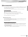 7
7
-
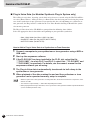 8
8
-
 9
9
-
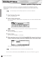 10
10
-
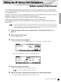 11
11
-
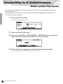 12
12
-
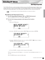 13
13
-
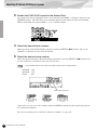 14
14
-
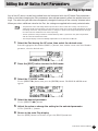 15
15
-
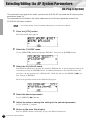 16
16
-
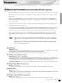 17
17
-
 18
18
-
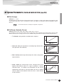 19
19
-
 20
20
-
 21
21
-
 22
22
-
 23
23
-
 24
24
-
 25
25
-
 26
26
-
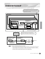 27
27
-
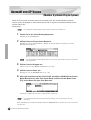 28
28
-
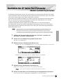 29
29
-
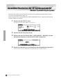 30
30
-
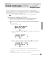 31
31
-
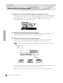 32
32
-
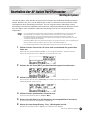 33
33
-
 34
34
-
 35
35
-
 36
36
-
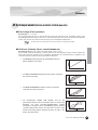 37
37
-
 38
38
-
 39
39
-
 40
40
-
 41
41
-
 42
42
-
 43
43
-
 44
44
-
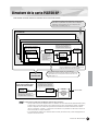 45
45
-
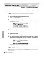 46
46
-
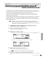 47
47
-
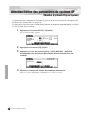 48
48
-
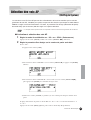 49
49
-
 50
50
-
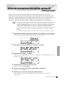 51
51
-
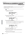 52
52
-
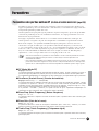 53
53
-
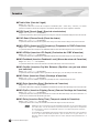 54
54
-
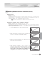 55
55
-
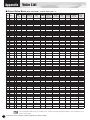 56
56
-
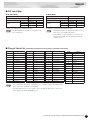 57
57
-
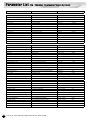 58
58
-
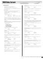 59
59
-
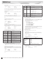 60
60
-
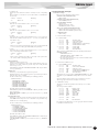 61
61
-
 62
62
-
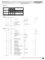 63
63
-
 64
64
-
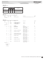 65
65
-
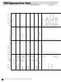 66
66
-
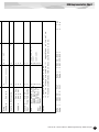 67
67
-
 68
68
-
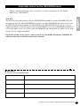 69
69
-
 70
70
-
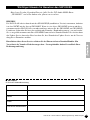 71
71
-
 72
72
-
 73
73
-
 74
74
-
 75
75
-
 76
76


Yamaha PLG150 El manual del propietario
- Categoría
- Pianos digitales
- Tipo
- El manual del propietario
- Este manual también es adecuado para
en otros idiomas
- français: Yamaha PLG150 Le manuel du propriétaire
- italiano: Yamaha PLG150 Manuale del proprietario
- English: Yamaha PLG150 Owner's manual
- Deutsch: Yamaha PLG150 Bedienungsanleitung
- русский: Yamaha PLG150 Инструкция по применению
- Nederlands: Yamaha PLG150 de handleiding
- português: Yamaha PLG150 Manual do proprietário
- dansk: Yamaha PLG150 Brugervejledning
- polski: Yamaha PLG150 Instrukcja obsługi
- čeština: Yamaha PLG150 Návod k obsluze
- svenska: Yamaha PLG150 Bruksanvisning
- Türkçe: Yamaha PLG150 El kitabı
- suomi: Yamaha PLG150 Omistajan opas
- română: Yamaha PLG150 Manualul proprietarului
Artículos relacionados
-
Yamaha PLG150 El manual del propietario
-
-
-
Yamaha PLG150-PC El manual del propietario
-
-
-
Yamaha S90 ES Manual de usuario
-
-
-
Yamaha Card Filer Manual de usuario