Behringer TN6232 Guía de inicio rápido
- Categoría
- Equipo de música suplementario
- Tipo
- Guía de inicio rápido
La página se está cargando ...

LEGAL DISCLAIMER
LIMITED WARRANTY
Important Safety
Instructions
Instrucciones de
seguridad
Terminals marked with this
symbol carry electrical
current of su cient
magnitude to constitute risk of electric
shock. Use only high-quality professional
speaker cables with ¼" TS or twist-
locking plugs pre-installed. Allother
installation or modi cation should be
performed only by quali edpersonnel.
This symbol, wherever it
appears, alerts you to the
presence of uninsulated
dangerous voltage inside the enclosure -
voltage that may be su cient to
constitute a risk ofshock.
This symbol, wherever it
appears, alerts you to
important operating and
maintenance instructions in the
accompanying literature. Please read
themanual.
Caution
To reduce the risk of electric
shock, do not remove the
top cover (or the rear section). No user
serviceable parts inside. Refer servicing
to quali edpersonnel.
Caution
To reduce the risk of re or
electric shock, do not expose
this appliance to rain and moisture.
Theapparatus shall not be exposed to
dripping or splashing liquids and no
objects lled with liquids, such as vases,
shall be placed on the apparatus.
Caution
These service instructions
are for use by quali ed
service personnel only. Toreduce the
risk of electric shock do not perform any
servicing other than that contained in the
operation instructions. Repairshave to be
performed by quali ed servicepersonnel.
1. Read these instructions.
2. Keep these instructions.
3. Heed all warnings.
4. Follow all instructions.
5. Do not use this apparatus
near water.
6. Clean only with dry cloth.
7. Do not block any ventilation
openings. Install in accordance with the
manufacturer’s instructions.
8. Do not install near any heat sources
such as radiators, heat registers, stoves,
or other apparatus (including ampli ers)
that produce heat.
9. Do not defeat the safety purpose
of the polarized or grounding-type plug.
A polarized plug has two blades with
one wider than the other. A grounding-
type plug has two blades and a third
grounding prong. The wide blade or the
third prong are provided for your safety.
Ifthe provided plug does not t into
your outlet, consult an electrician for
replacement of the obsolete outlet.
10. Protect the power cord from being
walked on or pinched particularly at
plugs, convenience receptacles, and the
point where they exit from the apparatus.
11. Use only attachments/accessories
speci ed by themanufacturer.
12. Use only with
the cart, stand,
tripod, bracket, or
table speci ed by the
manufacturer, orsold
with the apparatus.
When a cart is used, use caution when
moving the cart/apparatus combination
to avoid injury from tip-over.
13. Unplug this apparatus during
lightning storms or when unused for long
periods of time.
14. Refer all servicing to quali ed
service personnel. Servicing is required
when the apparatus has been damaged
in any way, such as power supply cord or
plug is damaged, liquid has been spilled
or objects have fallen into the apparatus,
the apparatus has been exposed to rain
or moisture, does not operate normally,
or has beendropped.
15. The apparatus shall be connected to
a MAINS socket outlet with a protective
earthing connection.
16. Where the MAINS plug or an
appliance coupler is used as the
disconnect device, the disconnect device
shall remain readily operable.
17. Correct disposal of
this product: This symbol
indicates that this product
must not be disposed of
with household waste,
according to the WEEE Directive
(2012/19/EU) and your national law.
This product should be taken to a
collection center licensed for the
recycling of waste electrical and
electronic equipment (EEE).
The mishandling of this type of waste
could have a possible negative impact on
the environment and human health due
to potentially hazardous substances that
are generally associated with EEE. At the
same time, your cooperation in the
correct disposal of this product will
contribute to the e cient use of natural
resources. For more information about
where you can take your waste
equipment for recycling, please contact
your local city o ce, or your household
waste collection service.
MUSIC Group accepts no liability for
any loss which may be su ered by any
person who relies either wholly or in
part upon any description, photograph,
or statement contained herein.
Technical speci cations, appearances and
other information are subject to change
without notice. All trademarks are the
property of their respective owners.
MIDAS, KLARK TEKNIK, TURBOSOUND,
BEHRINGER, BUGERA and DDA are
trademarks or registered trademarks of
MUSIC Group IP Ltd. © MUSIC Group IP
Ltd. 2015 All rights reserved.
For the applicable warranty terms and
conditions and additional information
regarding MUSIC Group’s Limited
Warranty, please see complete details
online at music-group.com/warranty.
Las terminales marcadas con
este símbolo transportan
corriente eléctrica de
magnitud su ciente como para constituir
un riesgo de descarga eléctrica.
Utilicesolo cables de altavoz
profesionales y de alta calidad con
conectores TS de 6,3 mm o de bayoneta
pre jados. Cualquier otra instalación o
modi cación debe ser realizada
únicamente por un técnicocuali cado.
Este símbolo, siempre que
aparece, leadvierte de la
presencia de voltaje
peligroso sin aislar dentro de la caja;
estevoltaje puede ser su ciente para
constituir un riesgo dedescarga.
Este símbolo, siempre que
aparece, leadvierte sobre
instrucciones operativas y
de mantenimiento que aparecen en la
documentación adjunta. Por favor,
leaelmanual.
Atención
Para reducir el riesgo de
descarga eléctrica, no quite
la tapa (olaparte posterior). Nohay
piezas en el interior del equipo que
puedan ser reparadas por el usuario.
Sies necesario, póngase en contacto con
personal cuali cado.
Atención
Para reducir el riesgo
de incendio o descarga
eléctrica, no exponga este aparato a la
lluvia, humedad o alguna otra fuente que
pueda salpicar o derramar algún líquido
sobre el aparato. Nocoloque ningún
tipo de recipiente para líquidos sobre
elaparato.
Atención
Las instrucciones de servicio
deben llevarlas a cabo
exclusivamente personal cuali cado.
Paraevitar el riesgo de una descarga
eléctrica, no realice reparaciones que no
se encuentren descritas en el manual
de operaciones. Lasreparaciones deben
ser realizadas exclusivamente por
personalcuali cado.
1. Lea las instrucciones.
2. Conserve estas instrucciones.
3. Preste atención a todas
las advertencias.
4. Siga todas las instrucciones.
5. No use este aparato cerca del agua.
6. Limpie este aparato con un
paño seco.
7. No bloquee las aberturas de
ventilación. Instale el equipo de acuerdo
con las instrucciones del fabricante.
8. No instale este equipo cerca de
fuentes de calor tales como radiadores,
acumuladores de calor, estufas u otros
aparatos (incluyendo ampli cadores)
que puedan producir calor.
9. No elimine o deshabilite nunca la
conexión a tierra del aparato o del cable
de alimentación de corriente. Unenchufe
polarizado tiene dos polos, uno de los
cuales tiene un contacto más ancho que
el otro. Una clavija con puesta a tierra
dispone de tres contactos: dos polos y
la puesta a tierra. El contacto ancho y el
tercer contacto, respectivamente, son los
que garantizan una mayor seguridad.
Si el enchufe suministrado con el equipo
no concuerda con la toma de corriente,
consulte con un electricista para cambiar
la toma de corriente obsoleta.
10. Coloque el cable de suministro de
energía de manera que no pueda ser
pisado y que esté protegido de objetos
a lados. Asegúrese de que el cable de
suministro de energía esté protegido,
especialmente en la zona de la clavija y en
el punto donde sale del aparato.
11. Use únicamente los dispositivos o
accesorios especi cados por el fabricante.
12. Use únicamente
la carretilla,
plataforma, trípode,
soporte o mesa
especi cados por el
fabricante o
suministrados junto con el equipo.
Altransportar el equipo, tenga cuidado
para evitar daños y caídas al tropezar con
algún obstáculo.
13. Desenchufe el equipo durante
tormentas o si no va a utilizarlo durante
un periodo largo.
14. Confíe las reparaciones únicamente
a servicios técnicos cuali cados.
La unidad requiere mantenimiento
siempre que haya sufrido algún daño,
si el cable de suministro de energía o el
enchufe presentaran daños, sehubiera
derramado un líquido o hubieran caído
objetos dentro del equipo, si el aparato
hubiera estado expuesto a la humedad
o la lluvia, si ha dejado de funcionar de
manera normal o si ha sufrido algún
golpe o caída.
15. Al conectar la unidad a la toma de
corriente eléctrica asegúrese de que la
conexión disponga de una unión atierra.
16. Si el enchufe o conector de red
sirve como único medio de desconexión,
éste debe ser accesiblefácilmente.
17. Cómo debe
deshacerse de este
aparato: Este símbolo
indica que este aparato no
debe ser tratado como
basura orgánica, según lo indicado en la
Directiva WEEE (2012/19/EU) y a las
normativas aplicables en su país. En lugar
de ello deberá llevarlo al punto limpio
más cercano para el reciclaje de sus
elementos eléctricos/ electrónicos (EEE).
Al hacer esto estará ayudando a prevenir
las posibles consecuencias negativas para
el medio ambiente y la salud que podrían
ser provocadas por una gestión
inadecuada de este tipo de aparatos.
Además, el reciclaje de materiales
ayudará a conservar los recursos
naturales. Para más información acerca
del reciclaje de este aparato, póngase en
contacto con el Ayuntamiento de su
ciudad o con el punto limpio local.
2 3Quick Start GuideFEEDBACK DESTROYER TN6232
La página se está cargando ...
La página se está cargando ...
La página se está cargando ...

(EN) Step 2: Controls
(ES) Paso 2: Controles
(FR) Étape 2 : Réglages
(DE) Schritt 2: Regler
(PT) Passo 2: Controlos
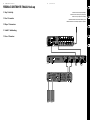
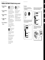
FEEDBACK DESTROYER TN6232 Controls
RACK BRACKETS and
MAGNETIC COVERS
are supplied with
the unit for rack-
mountinstallation
Con la unidad se
incluyen ESCUADRAS
PARA COLOCACIÓN
EN RACK y TAPAS
MAGNÉTICAS para
su instalaci—n en un
bastidor rack.
Les ÉQUERRES
DE RACK et les
PROTECTIONS
MAGNÉTIQUES sont
fournies avec l’appareil
pour l’installation
enRack.
RACK-HALTERUNGEN
und MAGNETISCHE
KAPPEN werden für
die Rack- Installation
mitgeliefert.
SUPORTE DE RACK
e COBERTURAS
MAGNÉTICAS são
fornecidos com
a unidade para
instalação em armação
de rack.
Fixed Front Panel
Panel frontal jo
Face avant xe
Fest installierte
Frontseite
Painel Frontal Fixo
DOOR covers the
controlsurface.
TAPA cubre la
super cie de control.
La PORTE recouvre
lesréglages.
KLAPPDECKEL schützt
das Bedienfeld.
PORTA cobre a
superfície de controle.
POWER INDICATOR
glows amber when the
unit is powered on.
El INDICADOR DE
ENCENDIDO se
ilumina en color
naranja cuando la
unidad estéencendida.
Le TÉMOIN
D’ALIMENTATION
s’allume en jaune
lorsque l’appareil est
sous tension.
NETZANZEIGE
leuchtet bei
eingeschaltetem
Gerätgelb.
INDICADOR DE
POTÊNCIA iIumina-se
com uma cor âmbar
quando a unidade
estáligada.
POWER SOURCE jack
accepts the included
IEC power cable.
La toma de ENTRADA
DE CORRIENTE
acepta el cable
de alimentación
IECincluido.
L’e mba se SECTEUR
accepte le cordon
IECfourni.
NETZANSCHLUSS
für das mitgelieferte
IEC-Netzkabel.
A tomada de FONTE
DE ENERGIA aceita o
cabo de alimentação
incluído IEC.
INPUTS section
features XLR/TRS
combination jacks
and 3-pin Euroblock
connectors wired
in parallel and will
accept balanced or
unbalanced line-
levelsignals.
La sección INPUT
dispone de
entradas en clavijas
combinadas XLR/TRS
y Euroconectores de
3puntas cableados
en paralelo y
aceptarán señales
de nivel de l’nea
balanceadas o
nobalanceadas.
La section des
entrées INPUTS est
équipée d’embases
combinées XLR/ Jack
stéréo et connecteurs
3-broches Euroblock,
connectés en
parallèle et qui
acceptent des
signaux symétriques
ou asymétriques à
niveauligne.
INPUT-Sektion.
Die XLR/ TRS-
Kombibuchsen und
3-Pol Euroblock-
Anschlüsse sind
parallel verdrahtet
und akzeptieren
symmetrische oder
unsymmetrische
Signale mit
Line-Pegel.
A seção ENTRADAS
é equipada com
uma combinação
XLR/TRS de tomadas
e conectores
Euroblock de 3pinos
com ação em
paralelo e aceita
sinais de n’vel de
linha balanceados ou
nãobalanceados.
OUTPUTS section
features XLR and 3-pin
Euroblock connectors
are wired in parallel
and drive balanced or
unbalancedloads.
La sección OUTPUT
dispone de salidas
en conectores XLR y
Euroconectores de
3puntas cableados
en paralelo y capaces
de usar cargas
balanceadas o
nobalanceadas.
La section OUTPUTS
est équipée d’embases
XLR et Euroblock
3broches câblées en
parall le et qui peuvent
alimenter des charges
symétriques ou
asymétriques.
OUTPUT-Sektion.
Die XLR- und
3-Pol Euroblock-
Anschlüsse sind
parallel verdrahtet
und betreiben
symmetrische oder
uns
ymmetrische
Lasten.
A seção SAÍDAS
é equipada com
conectores XLR
e Euroblock de
3pinos com ação
em paralelo e com
cargas balanceadas
ou não balanceadas.
unbalanced loads.
10 FEEDBACK DESTROYER TN6232 11 Quick Start Guide

12 FEEDBACK DESTROYER TN6232 13 Quick Start Guide
(EN) Step 2: Controls
(ES) Paso 2: Controles
(FR) Étape 2 : Réglages
(DE) Schritt 2: Regler
(PT) Passo 2: Controlos
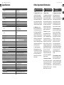
FEEDBACK DESTROYER TN6232 Controls
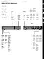
RESET LED illuminates
when the FILTER RESET
button is pressed.
Aseries of ashes
indicate memory has
been cleared and
lters have been reset.
El PILOTO RESET se
ilumina cuando haya
pulsado el botón
FILTER RESET. Una serie
de parpadeos indican
que la memoria
ha sido borrada y
que los ltros han
sidoreiniciados.
La LED RESET s’allume
lorsque vous appuyez
sur la touche FILTER
RESET. Une série de
clignotements indique
que la mémoire est
initialisée ainsi que
les ltres.
RESET LED leuchtet
nach dem Drücken der
FILTER RESET-Taste.
Mehrfaches Blinken
weist darauf hin,
dass der Speicher
gelöscht und die Filter
zurückgesetztwurden.
LED RESET ilumina-
se quando o botão
FILTER RESET está
pressionado. Umasérie
de ashes indica que
a memória foi limpa
e que os ltros foram
recon gurados.
POWER SWITCH turns
the unit on and o .
El INTERRUPTOR
POWER le permite
encender y apagar
launidad.
L’INTERRUPTEUR
secteur place l’appareil
sous/hors tension.
NETZSCHALTER
zum Ein/Ausschalten
desGeräts.
INTERRUPTOR DE
ALIMENTAÇÃO Liga e
desliga a unidade.
SUPPRESSION switch
toggles between
ACTIVE and BYPASS
modes. In ACTIVE
mode, the automatic
lters are engaged.
In BYPASS mode, the
lters are bypassed
and signal will
pass through the
unitunaltered.
El interruptor
SUPPRESSION le
permite cambiar
entre los modos
ACTIVE y BYPASS.
Enel modo ACTIVE,
los ltros automáticos
estarán activados.
En BYPASS, los ltros
estarán anulados
y la señal pasará a
través de la unidad sin
verseafectada.
La touche
SUPPRESSION
sélectionne le mode
ACTIVE ou BYPASS.
Enmode ACTIF,
les ltres automatiques
sont activés. Enmode
BYPASS, les ltres
sont bipassés et
le signal passe
dans le processeur
sanstraitement.
SUPPRESSION-
Schalter wechselt
zwischen ACTIVE-und
BYPASS-Modus.
ImACTIVE-Modus sind
die automatischen
Filter aktiviert. Im
BYPASS-Modus
werden die Filter
umgangen und das
Signal durchläuft das
Gerät unverändert.
O botão
SUPPR
ESSION se
alterna entre os modos
ACTIVE e BYPASS.
No modo ACTIVE,
os ltros automáticos
estão engajados.
Nomodo BYPASS,
os ltros são anulados
e o sinal passa através
da unidade sem
sofreralteração.
ACTIVE LED indicates
unit is in ACTIVE mode.
El PILOTO ACTIVE le
indica que la unidad
está en dicho modo.
La LED ACTIVE indique
que le processeur est
en mode ACTIF.
ACTIVE LED leuchtet,
wenn das Gerät im
ACTIVE-Modus ist.
LED ATIVO indica que
a unidade está em
modoATIVO.
BYPASS LED
indicates unit is in
BYPASSmode.
El PILOTO BYPASS
le indica que la
unidad está en el
modoBYPASS.
La LED BYPASS
indique le
modeBYPASS.
BYPASS LED leuchtet,
wenn das Gerät im
BYPASS-Modus ist.
LED BYPASS indica
que a unidade está em
modo BYPASS .
FILTER RESET switch
resets the lters and
clears the memory.
El interruptor FILTER
RESET hace que los
ltros sean reiniciados
y borra la memoria.
La touche FILTER
RESET initialise
les ltres et vide
lamémoire.
FILTER RESET-
Schalter setzt die Filter
zurück und löscht
denSpeicher.
O botão FILTER RESET
recon gura os ltros e
limpa a memória.
EUROCOM TN 6232

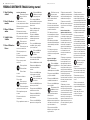
(EN) Step 3: Getting
started
(ES) Paso 3: Puesta en
marcha
(FR) Étape 3 : Mise en
œuvre
(DE) Schritt 3: Erste
Schritte
(PT) Passo 3: Primeiros
Passos
Initial Setup / Ersteinrichtung
(EN) Make all appropriate audio
and power connections to
theTN6232.
(ES) Realice todas las conexiones
(eléctricasy audio) adecuadas en el TN6232.
(FR) Réalisez toutes les connexions audio et
d’alimentation au TN6232.
(DE) Nehmen Sie alle erforderlichen
Audio- und Netzanschlüsse am TN6232 vor.
(PT) Faça todas as conexões de áudio e de
alimentação apropriadas com o TN6232.
(EN) Power up the sound
system’s preamp ormixer.
(ES) Encienda el previo o mesa
de mezclas de su sistema de sonido.
(FR) Placez le préampli ou la console
soustension.
(DE) Schalten Sie den Vorverstärker oder
Mischer des Soundsystems ein.
(PT) Ligue o pré-amp ou o mixer do
sistemadesom.
(EN) Power up the TN6232.
(ES) Encienda el TN6232.
(FR) Placez le TN6232
soustension.
(DE) Schalten Sie den TN6232 ein.
(PT) Ligue o TN6232.
(EN) Power up the sound
system’s powerampli er.
(ES) Encienda el ampli cador o
etapa de potencia de su sistema de sonido.
(FR) Placez l’ampli cateur de puissance
soustension.
(DE) Schalten Sie die Endstufe des
Soundsystems ein.
(PT) Ligue o ampli cador do sistema de som.
(EN) With the SUPPRESSION set
to BYPASS mode, set the gain for
normal systemoperation.
(ES) Con el interruptor SUPPRESSION
ajustado al modo BYPASS, ajuste la ganancia
para un funcionamiento normal de su
sistema desonido.
(FR) Avec la SUPPRESSION con gurée
en BYPASS, réglez le gain pour un
fonctionnement normal.
(DE) Schalten Sie SUPPRESSION in
den BYPASS-Modus und stellen Sie
die Verstärkung für den normalen
Systembetriebein.
(PT) Com o botão SUPPRESSION con gure
o modo BYPASS, con gure o ganho para
opera’o de sistema normal.
(EN) Press the SUPPRESSION
button to set the unit to
ACTIVEmode.
(ES) Pulse el interruptor SUPPRESSION para
activar la unidad al modo ACTIVE.
(FR) Placez la SUPPRESSION en mode ACTIVE.
(DE) Drücken Sie die SUPPRESSION-Taste,
umdas Gerät in den ACTIVE-Modus
zuschalten.
(PT) Pressione o botão SUPPRESSION para
con gurar a unidade ao modo ACTIVE.
(EN) Press the FILTER RESET
button to clear the memory and
reset the lters.
(ES) Pulse el botón FILTER RESET para borrar
la memoria y reiniciar los ltros.
(FR) Appuyez sur la touche FILTER RESET pour
initialiser la mémoire et les ltres.
(DE) Drücken Sie die FILTER RESET-Taste,
um den Speicher zu löschen und die
Filterzurückzusetzen.
(PT) Pressione o botão FILTER RESET para
limpar a memória e recon gurar os ltros.
(EN) The TN6232 is now ready
for operation and will
automatically nd problem
frequencies and attenuate them to
eliminate feedback.
(ES) El TN6232 está ahora listo para
funcionar; detectará automáticamente las
frecuencias problemáticas y las atenuará
para eliminar la realimentación.
(FR) Le TN6232 est prêt à fonctionner.
Iltrouve automatiquement les fréquences
à la source du Larsen et les atténue pour
supprimer le Larsen.
(DE) Der TN6232 ist jetzt betriebsbereit
und wird automatisch Problemfrequenzen
erkennen und bedämpfen, um Feedback
zubeseitigen.
(PT) O TN6232 agora está pronto para
a operaçã; ele encontrará frequ ncias
problemáticas e as atenuará para eliminar
o feedback.
Bypass Mode / Modo Bypass /
Bypass-Modus / Modo Bypass
(EN) Press the SUPPRESSION
button to engage BYPASS mode.
(ES) Pulse el botón
SUPPRESSION para activar el modo BYPASS.
(FR) Appuyez sur la touche SUPPRESSION
pour passer en mode BYPASS.
(DE) Drücken Sie die SUPPRESSION-Taste,
umden BYPASS-Modus zu aktivieren.
(PT) Pressione o botão SUPPRESSION para
iniciar o modo BYPASS.
(EN) Switch between ACTIVE
and BYPASS mode to hear a
comparison between the
system’s operation with and without
feedback suppression.
(ES) Cambie entre el modo ACTIVE y el
BYPASS para realizar una comparación entre
el funcionamiento del sistema con y sin la
supresión de realimentación.
(FR) Passez entre les modes ACTIVE et
BYPASS pour comparer le signal avec et sans
suppression du Larsen.
(DE) Wechseln Sie zwischen den ACTIVE-
und BYPASS-Modi, um das System mit und
ohne Feedback-Unterdrückung zu hören
und die Betriebsarten zu vergleichen.
(PT) Alterne entre os modos ACTIVE e
BYPASS para ouvir uma comparação entre a
operação do sistema com e sem supressão
de feedback.
Filter Reset / Reinicio de ltro /
Initialisation de ltre / Filter-Reset
(EN) Over time, all of the 32 individual lters
per channel may be assigned to problem
frequencies, leavingno available lters
for new feedback incidents. If no lters
are available, it may be necessary to reset
the unit in order to accommodate the
suppression of new feedback frequencies
as they occur. Itmay also be necessary
to reset the unit in order to restore
the sound system’s tonal balance and
frequencyresponse.
(ES) Puede asignar a lo largo del tiempo
los 32 ltros individuales por canal a
frecuencias problemáticas, lo que no
dejará ningún ltro disponible en caso
de nuevos problemas de realimentación.
Si hay disponibles más ltros, es posible
que tenga que reiniciar la unidad de cara a
permitir la supresión de nuevas frecuencias
de realimentación segœn se vayan
produciendo. También puede que tenga
que reiniciar la unidad de cara a restaurar el
balance tonal y la respuesta de frecuencia
de su sistema de sonido.
(FR) Dans le temps, les 32 canaux
individuels par canal peuvent être a ectés
à des fréquences qui posent un problème,
ce qui ne laisse aucun ltre disponible pour
les nouveaux incidents de Larsen. Si aucun
ltre n’est disponible, vous risquez d’avoir
à initialiser le processeur a n de gérer la
suppression de nouveaux Larsen lors de leur
apparition. Initialisez alors le processeur
pour restaurer l’équilibre sonore global et la
réponse en fréquence.
(DE) Mit der Zeit werden alle
32Einzel lter pro Kanal verschiedenen
Problemfrequenzen zugeordnet sein,
wodurch keine Filter für neue Feedback-
Quellen mehr verfügbar sind. In diesem Fall
muss man das Gerät eventuell zurücksetzen,
um neu auftretende Feedback-Frequenzen
unterdrücken zu können. Eventuell muss
man das Gerät auch zurücksetzen, um die
klangliche Balance und den Frequenzgang
des Soundsystemswiederherzustellen.
(PT) Com o passar do tempo, todos os
32 ltros individuais por canal podem ser
designados a frequências problemática,
semdeixar nenhum ltro disponível para
novos incidentes de feedback. Se nenhum
itro estiver disponível, pode ser necessário
recon gurar a unidade para acomodar a
supressão das novas frequ ncias de feedback
conforme elas ocorram. Também pode ser
que seja necessário recon gurar a unidade
para restaurar o balan o tonal e a resposta
da frequência do sistema de som.
(EN) Before resetting the unit,
reduce the system gain
andensure that all
microphonesareo .
(ES) Antes de reiniciar la unidad, reduzcala
ganancia del sistema y asegúrese de que
todos los micrófonos estén desactivados.
(FR) Avant d’initialiser le processeur,
réduisezle gain global et désactivez tous
les micros.
(DE) Bevor Sie das Gerät zurücksetzen,
müssen Sie die Verstärkung des Systems
verringern und alle Mikrofone ausschalten.
(PT) Antes de recon gurar a
unidade, reduzao ganho do sistema
e certi que-se de que todos os
microfonesestejamdesligados.
FEEDBACK DESTROYER TN6232 Getting started
14 FEEDBACK DESTROYER TN6232 15 Quick Start Guide

16 FEEDBACK DESTROYER TN6232 17 Quick Start Guide
(EN) Step 3: Getting
started
(ES) Paso 3: Puesta en
marcha
(FR) Étape 3 : Mise en
œuvre
(DE) Schritt 3: Erste
Schritte
(PT) Passo 3: Primeiros
Passos
FEEDBACK DESTROYER TN6232 Getting started
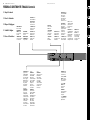
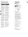
Connectors
Balanced XLR connectors ⁄ Conectores XLR balanceados ⁄
ConnecteursXLR symétriques ⁄ Symmetrische XLR-Anschlüsse ⁄
Conectores XLR balanceados
Balanced ¼ " TRS connector ⁄ Conector TRS de 6,3 mm balanceado ⁄
Jackstéréo 6,35 mm / Symmetrischer 6,35 mm TRS-Anschluss/
ConectorTRS de 6,3 mm balanceado
Unbalanced ¼ " TS connector ⁄ Conector TS de 6,3 mm no balanceado ⁄
Jack mono asymétrique 6,35 mm ⁄ Unsymmetrischer 6,35 mm
TS-Anschluss ⁄ Conector TS de 6,3 mm não balanceado
3-pin Euroblock Connector ⁄ Euroconector de 3 puntas ⁄
ConnecteurEuroblock 3 broches ⁄ 3-Pol Euroblock-Anschluss ⁄
Euroconector de 3 pinos
1 = ground/shield
2 = hot (+)
3 = cold (-)
input
12
3
output
1
2
3
strain relief clamp
sleeve
ring
tip
sleeve
ground/shield
ring
cold (-)
tip
hot (+)
strain relief clamp
sleeve
tip
sleeve
ground/shield
tip
signal
1
2
3
1. ground/shield
2. hot (+)
3. cold (-)
(EN) Press the RESET button.
TheLED ashes to indicate the
lters have been reset and the
memory is cleared of allsettings.
(ES) Pulse el botón RESET. Su piloto
parpadeará para indicar que los ltros han
sido reiniciados y que todos los ajustes han
sido borrados de la memoria.
(FR) Appuyez sur le bouton RESET. La Led
LED clignote, ce qui indique que les ltres
sont initialisés et que la mémoire est vide de
toutréglage.
(DE) Drücken Sie die RESET-Taste.
Dieblinkende LED zeigt an, dass alle Filter
zurückgesetzt und alle Einstellungen aus
dem Speicher gelöscht wurden.
(PT) Pressione o botão RESET. O LED irá
piscar para indicar que os ltros foram
recon gurados e que a memória está livre de
todas as con gurações.
(EN) Slowly increase the gain of
each microphone to proper
operating level.
(ES) Aumente lentamente la ganancia de
cada micrófono hasta conseguir el nivel
operativoadecuado.
(FR) Augmentez progressivement le gain de
chaque micro jusqu’au niveau normal.
(DE) Erhöhen Sie die Verstärkung
der Mikrofone langsam bis zum
korrektenBetriebspegel.
(PT) Aos poucos, aumente o ganho
de cada microfone para o nível de
operaçãoapropriado.
(EN) The TN6232 will
automatically detect and
suppress any
problemfrequencies.
(ES) El TN6232 detectará y eliminará
de forma automática cualquier
frecuenciaproblemática.
(FR) Le TN6232 détecte automatiquement les
fréquences incriminées et les atténue pour
supprimer le Larsen.
(DE) Der TN6232 erkennt und unterdrückt
alle Problemfrequenzen automatisch.
(PT) O TN6232 irá automaticamente detectar
e suprir todas as frequências problemáticas.

Speci cations Other important information
1. Register online. Pleaseregister
your new MUSIC Group equipment
right after you purchase it by visiting
behringer. com. Registeringyour purchase
using our simple online form helps us to
process your repair claims more quickly
and e ciently. Also, read the terms and
conditions of our warranty, ifapplicable.
2. Malfunction. Should your
MUSICGroup Authorized Reseller not be
located in your vicinity, you may contact
the MUSIC Group Authorized Ful ller for
your country listed under “Support” at
behringer. com. Shouldyour country not be
listed, pleasecheck if your problem can be
dealt with by our “OnlineSupport” which
may also be found under “Support” at
behringer. com. Alternatively, please submit
an online warranty claim at behringer. com
BEFORE returning theproduct.
3. Power Connections.
Beforeplugging the unit into a power
socket, please make sure you are using the
correct mains voltage for your particular
model. Faulty fuses must be replaced
with fuses of the same type and rating
withoutexception.
1. Registro online.
Lerecomendamos que registre su nuevo
aparato MUSIC Group justo después de
su compra accediendo a la página web
behringer. com. Elregistro de su compra a
través de nuestro sencillo sistema online
nos ayudará a resolver cualquier incidencia
que se presente a la mayor brevedad
posible. Además,aproveche para leer
los términos y condiciones de nuestra
garantía, siesaplicable en sucaso.
2. Averías. En el caso de que no
exista un distribuidor MUSIC Group en
las inmediaciones, puede ponerse en
contacto con el distribuidor MUSIC Group
de su país, queencontrará dentro del
apartado “Support” de nuestra página web
behringer. com. En caso de que su país no
aparezca en ese listado, acceda a la sección
“Online Support” (quetambiénencontrará
dentro del apartado “Support” de nuestra
páginaweb) y compruebe si su problema
aparece descrito y solucionado allí.
Deforma alternativa, envíenos a través
de la página web una solicitud online de
soporte en periodo de garantía ANTES de
devolvernoselaparato.
3. Conexiones de corriente.
Antes de enchufar este aparato a una salida
de corriente, asegúrese de que dicha salida
sea del voltaje adecuado para su modelo
concreto. En caso de que deba sustituir un
fusible quemado, deberáhacerlo por otro de
idénticas especi caciones, sinexcepción.
1. Enregistrez-vous enligne.
Prenezle temps d’enregistrer votre
produit MUSIC Group aussi vite que
possible sur le site Internet behringer. com.
Lefait d’enregistrer le produit en ligne
nous permet de gérer les réparations
plus rapidement et plus e cacement.
Prenezégalement le temps de lire les
termes et conditions de notregarantie.
2. Dysfonctionnement. Si vous
n’avez pas de revendeur MUSIC Group près
de chez vous, contactez le distributeur
MUSIC Group de votre pays: consultez la
liste des distributeurs de votre pays dans
la page “Support” de notre site Internet
behringer. com. Si votre pays n’est pas
dans la liste, essayez de résoudre votre
problème avec notre “aideen ligne”
que vous trouverez également dans la
section “Support” du site behringer. com.
Vouspouvez également nous faire parvenir
directement votre demande de réparation
sous garantie par Internet sur le site
behringer. com AVANT de nous renvoyer
leproduit.
3. Raccordement au secteur.
Avant de relier cet équipement au secteur,
assurez-vous que la tension secteur de
votre région soit compatible avec l’appareil.
Veillez à remplacer les fusibles uniquement
par des modèles exactement de même
taille et de même valeur électrique — sans
aucuneexception.
Important information
Aspectos importantes
Informations
importantes
18 19Quick Start GuideFEEDBACK DESTROYER TN6232
Audio Inputs
Connections
2 x X
LR / TRS combo
2 x 3-pin Euroblock
Input impedance appr. 10 kΩ
Normal input level +4 dBu
Max. input level +22 dBu
Audio Outputs
Connections
2 x X
LR
2 x 3-pin Euroblock
Output impedance appr. 120 Ω
Normal output level +4 dBu
Max. output level +22 dBu
System Information
Controls
P
ower on / o
Suppression (momentary)
Filter reset (momentary)
Indicators
Behringer logo (Power on)
Active
Bypass
Reset
Frequency response 20 Hz – 20 kHz, ± 0.5 dB
Dynamic range 102 dB A-weighted, > 100 dB audio lter
THD+N < 0.1 % @ 20 Hz – 20 kHz
Crosstalk < -100 dB, -120 dB typical
S/N Ratio ≥ 100 dB
CMRR > 45 dB
Processer system gain 0 dB
Additional acoustic gain 10 dB
Digital Signal Processing (DSP)
Converters 24-bit
S
ample rate 48 kHz
Feedback Suppressor (FBQ)
Feedback reduction method Automatically detect and apply notch lter
F
ilters 32 independent digital notch lters per channel
Filter width min. 1/126th octave, max. 1/38th octave
Resolution 0.2 Hz
Time required to nd one feedback mode 100 – 400 msec
Time required to nd multiple feedback modes 2 – 4 sec
Power Supply (Fuses)
Type Auto-switching power supply
M
ains voltage (all regions) 100 – 240 VAC, 50/60 Hz
Fuse T 1.25 A H 250 V
Power consumption appr. 10 W
Mains connector Standard IEC receptacle
Dimensions / Weight
Dimensions (H x W x D) appr. 44 x 482 x 192 mm (1U) (appr. 1.7 x 19 x 7.6")
We
ight appr. 2.1 kg (appr. 4.6 lbs)
La página se está cargando ...
La página se está cargando ...
Transcripción de documentos
2 FEEDBACK DESTROYER TN6232 Important Safety Instructions Terminals marked with this symbol carry electrical current of sufficient magnitude to constitute risk of electric shock. Use only high-quality professional speaker cables with ¼" TS or twistlocking plugs pre-installed. All other installation or modification should be performed only by qualified personnel. This symbol, wherever it appears, alerts you to the presence of uninsulated dangerous voltage inside the enclosure voltage that may be sufficient to constitute a risk of shock. This symbol, wherever it appears, alerts you to important operating and maintenance instructions in the accompanying literature. Please read the manual. Caution To reduce the risk of electric shock, do not remove the top cover (or the rear section). No user serviceable parts inside. Refer servicing to qualified personnel. Caution To reduce the risk of fire or electric shock, do not expose this appliance to rain and moisture. The apparatus shall not be exposed to dripping or splashing liquids and no objects filled with liquids, such as vases, shall be placed on the apparatus. Caution These service instructions are for use by qualified service personnel only. To reduce the risk of electric shock do not perform any servicing other than that contained in the operation instructions. Repairs have to be performed by qualified service personnel. Quick Start Guide 1. Read these instructions. 2. Keep these instructions. 3. Heed all warnings. 4. Follow all instructions. 5. Do not use this apparatus near water. 6. Clean only with dry cloth. 7. Do not block any ventilation openings. Install in accordance with the manufacturer’s instructions. 8. Do not install near any heat sources such as radiators, heat registers, stoves, or other apparatus (including amplifiers) that produce heat. 9. Do not defeat the safety purpose of the polarized or grounding-type plug. A polarized plug has two blades with one wider than the other. A groundingtype plug has two blades and a third grounding prong. The wide blade or the third prong are provided for your safety. If the provided plug does not fit into your outlet, consult an electrician for replacement of the obsolete outlet. 10. Protect the power cord from being walked on or pinched particularly at plugs, convenience receptacles, and the point where they exit from the apparatus. 11. Use only attachments/accessories specified by the manufacturer. 12. Use only with the cart, stand, tripod, bracket, or table specified by the manufacturer, or sold with the apparatus. When a cart is used, use caution when moving the cart/apparatus combination to avoid injury from tip-over. 13. Unplug this apparatus during lightning storms or when unused for long periods of time. 14. Refer all servicing to qualified service personnel. Servicing is required when the apparatus has been damaged in any way, such as power supply cord or plug is damaged, liquid has been spilled or objects have fallen into the apparatus, the apparatus has been exposed to rain or moisture, does not operate normally, or has been dropped. 15. The apparatus shall be connected to a MAINS socket outlet with a protective earthing connection. 16. Where the MAINS plug or an appliance coupler is used as the disconnect device, the disconnect device shall remain readily operable. 17. Correct disposal of this product: This symbol indicates that this product must not be disposed of with household waste, according to the WEEE Directive (2012/19/EU) and your national law. This product should be taken to a collection center licensed for the recycling of waste electrical and electronic equipment (EEE). The mishandling of this type of waste could have a possible negative impact on the environment and human health due to potentially hazardous substances that are generally associated with EEE. At the same time, your cooperation in the correct disposal of this product will contribute to the efficient use of natural resources. For more information about where you can take your waste equipment for recycling, please contact your local city office, or your household waste collection service. LEGAL DISCLAIMER MUSIC Group accepts no liability for any loss which may be suffered by any person who relies either wholly or in part upon any description, photograph, or statement contained herein. Technical specifications, appearances and other information are subject to change without notice. All trademarks are the property of their respective owners. MIDAS, KLARK TEKNIK, TURBOSOUND, BEHRINGER, BUGERA and DDA are trademarks or registered trademarks of MUSIC Group IP Ltd. © MUSIC Group IP Ltd. 2015 All rights reserved. LIMITED WARRANTY For the applicable warranty terms and conditions and additional information regarding MUSIC Group’s Limited Warranty, please see complete details online at music-group.com/warranty. Instrucciones de seguridad Las terminales marcadas con este símbolo transportan corriente eléctrica de magnitud suficiente como para constituir un riesgo de descarga eléctrica. Utilice solo cables de altavoz profesionales y de alta calidad con conectores TS de 6,3 mm o de bayoneta prefijados. Cualquier otra instalación o modificación debe ser realizada únicamente por un técnico cualificado. Este símbolo, siempre que aparece, le advierte de la presencia de voltaje peligroso sin aislar dentro de la caja; este voltaje puede ser suficiente para constituir un riesgo de descarga. Este símbolo, siempre que aparece, le advierte sobre instrucciones operativas y de mantenimiento que aparecen en la documentación adjunta. Por favor, lea el manual. Atención Para reducir el riesgo de descarga eléctrica, no quite la tapa (o la parte posterior). No hay piezas en el interior del equipo que puedan ser reparadas por el usuario. Si es necesario, póngase en contacto con personal cualificado. Atención Para reducir el riesgo de incendio o descarga eléctrica, no exponga este aparato a la lluvia, humedad o alguna otra fuente que pueda salpicar o derramar algún líquido sobre el aparato. No coloque ningún tipo de recipiente para líquidos sobre el aparato. Atención Las instrucciones de servicio deben llevarlas a cabo exclusivamente personal cualificado. Para evitar el riesgo de una descarga eléctrica, no realice reparaciones que no se encuentren descritas en el manual de operaciones. Las reparaciones deben ser realizadas exclusivamente por personal cualificado. 1. Lea las instrucciones. 2. Conserve estas instrucciones. 3. Preste atención a todas las advertencias. 4. Siga todas las instrucciones. 5. No use este aparato cerca del agua. 6. Limpie este aparato con un paño seco. 7. No bloquee las aberturas de ventilación. Instale el equipo de acuerdo con las instrucciones del fabricante. 8. No instale este equipo cerca de fuentes de calor tales como radiadores, acumuladores de calor, estufas u otros aparatos (incluyendo amplificadores) que puedan producir calor. 9. No elimine o deshabilite nunca la conexión a tierra del aparato o del cable de alimentación de corriente. Un enchufe polarizado tiene dos polos, uno de los cuales tiene un contacto más ancho que el otro. Una clavija con puesta a tierra dispone de tres contactos: dos polos y la puesta a tierra. El contacto ancho y el tercer contacto, respectivamente, son los que garantizan una mayor seguridad. Si el enchufe suministrado con el equipo no concuerda con la toma de corriente, consulte con un electricista para cambiar la toma de corriente obsoleta. 10. Coloque el cable de suministro de energía de manera que no pueda ser pisado y que esté protegido de objetos afilados. Asegúrese de que el cable de suministro de energía esté protegido, especialmente en la zona de la clavija y en el punto donde sale del aparato. 11. Use únicamente los dispositivos o accesorios especificados por el fabricante. 3 12. Use únicamente la carretilla, plataforma, trípode, soporte o mesa especificados por el fabricante o suministrados junto con el equipo. Al transportar el equipo, tenga cuidado para evitar daños y caídas al tropezar con algún obstáculo. 13. Desenchufe el equipo durante tormentas o si no va a utilizarlo durante un periodo largo. 14. Confíe las reparaciones únicamente a servicios técnicos cualificados. La unidad requiere mantenimiento siempre que haya sufrido algún daño, si el cable de suministro de energía o el enchufe presentaran daños, se hubiera derramado un líquido o hubieran caído objetos dentro del equipo, si el aparato hubiera estado expuesto a la humedad o la lluvia, si ha dejado de funcionar de manera normal o si ha sufrido algún golpe o caída. 15. Al conectar la unidad a la toma de corriente eléctrica asegúrese de que la conexión disponga de una unión a tierra. 16. Si el enchufe o conector de red sirve como único medio de desconexión, éste debe ser accesible fácilmente. 17. Cómo debe deshacerse de este aparato: Este símbolo indica que este aparato no debe ser tratado como basura orgánica, según lo indicado en la Directiva WEEE (2012/19/EU) y a las normativas aplicables en su país. En lugar de ello deberá llevarlo al punto limpio más cercano para el reciclaje de sus elementos eléctricos / electrónicos (EEE). Al hacer esto estará ayudando a prevenir las posibles consecuencias negativas para el medio ambiente y la salud que podrían ser provocadas por una gestión inadecuada de este tipo de aparatos. Además, el reciclaje de materiales ayudará a conservar los recursos naturales. Para más información acerca del reciclaje de este aparato, póngase en contacto con el Ayuntamiento de su ciudad o con el punto limpio local. 10 FEEDBACK DESTROYER TN6232 11 Quick Start Guide FEEDBACK DESTROYER TN6232 Controls (EN) Step 2: Controls (ES) Paso 2: Controles DOOR covers the control surface. (FR) Étape 2 : Réglages TAPA cubre la superficie de control. (DE) Schritt 2: Regler La PORTE recouvre les réglages. KLAPPDECKEL schützt das Bedienfeld. (PT) Passo 2: Controlos RACK BRACKETS and MAGNETIC COVERS are supplied with the unit for rackmount installation RACK-HALTERUNGEN und MAGNETISCHE KAPPEN werden für die Rack- Installation mitgeliefert. Con la unidad se incluyen ESCUADRAS PARA COLOCACIÓN EN RACK y TAPAS MAGNÉTICAS para su instalaci—n en un bastidor rack. SUPORTE DE RACK e COBERTURAS MAGNÉTICAS são fornecidos com a unidade para instalação em armação de rack. Les ÉQUERRES DE RACK et les PROTECTIONS MAGNÉTIQUES sont fournies avec l’appareil pour l’installation en Rack. PORTA cobre a superfície de controle. POWER INDICATOR glows amber when the unit is powered on. El INDICADOR DE ENCENDIDO se ilumina en color naranja cuando la unidad esté encendida. Le TÉMOIN D’ALIMENTATION s’allume en jaune lorsque l’appareil est sous tension. NETZANZEIGE leuchtet bei eingeschaltetem Gerät gelb. INDICADOR DE POTÊNCIA iIumina-se com uma cor âmbar quando a unidade está ligada. POWER SOURCE jack accepts the included IEC power cable. Fixed Front Panel Panel frontal fijo Face avant fixe Fest installierte Frontseite Painel Frontal Fixo La toma de ENTRADA DE CORRIENTE acepta el cable de alimentación IEC incluido. L’embase SECTEUR accepte le cordon IEC fourni. NETZANSCHLUSS für das mitgelieferte IEC-Netzkabel. A tomada de FONTE DE ENERGIA aceita o cabo de alimentação incluído IEC. OUTPUTS section features XLR and 3-pin Euroblock connectors are wired in parallel and drive balanced or unbalanced loads. La section OUTPUTS est équipée d’embases XLR et Euroblock 3 broches câblées en parall le et qui peuvent alimenter des charges symétriques ou asymétriques. La sección OUTPUT dispone de salidas en conectores XLR y Euroconectores de 3 puntas cableados en paralelo y capaces de usar cargas balanceadas o no balanceadas. OUTPUT-Sektion. Die XLR- und 3-Pol EuroblockAnschlüsse sind parallel verdrahtet und betreiben symmetrische oder unsymmetrische Lasten. A seção SAÍDAS é equipada com conectores XLR e Euroblock de 3 pinos com fiação em paralelo e com cargas balanceadas ou não balanceadas. unbalanced loads. INPUTS section features XLR/TRS combination jacks and 3-pin Euroblock connectors wired in parallel and will accept balanced or unbalanced linelevel signals. La section des entrées INPUTS est équipée d’embases combinées XLR/ Jack stéréo et connecteurs 3-broches Euroblock, connectés en parallèle et qui acceptent des signaux symétriques ou asymétriques à niveau ligne. La sección INPUT dispone de entradas en clavijas combinadas XLR/TRS y Euroconectores de 3 puntas cableados en paralelo y aceptarán señales de nivel de l’nea balanceadas o no balanceadas. INPUT-Sektion. Die XLR/ TRSKombibuchsen und 3-Pol EuroblockAnschlüsse sind parallel verdrahtet und akzeptieren symmetrische oder unsymmetrische Signale mit Line-Pegel. A seção ENTRADAS é equipada com uma combinação XLR/TRS de tomadas e conectores Euroblock de 3 pinos com fiação em paralelo e aceita sinais de n’vel de linha balanceados ou não balanceados. 12 FEEDBACK DESTROYER TN6232 13 Quick Start Guide FEEDBACK DESTROYER TN6232 Controls (EN) Step 2: Controls (ES) Paso 2: Controles ACTIVE LED indicates unit is in ACTIVE mode. (FR) Étape 2 : Réglages El PILOTO ACTIVE le indica que la unidad está en dicho modo. El INTERRUPTOR POWER le permite encender y apagar la unidad. NETZSCHALTER zum Ein/Ausschalten des Geräts. ACTIVE LED leuchtet, wenn das Gerät im ACTIVE-Modus ist. El PILOTO BYPASS le indica que la unidad está en el modo BYPASS. BYPASS LED leuchtet, wenn das Gerät im BYPASS-Modus ist. El PILOTO RESET se ilumina cuando haya pulsado el botón FILTER RESET. Una serie de parpadeos indican que la memoria ha sido borrada y que los filtros han sido reiniciados. L’INTERRUPTEUR secteur place l’appareil sous/hors tension. INTERRUPTOR DE ALIMENTAÇÃO Liga e desliga a unidade. LED ATIVO indica que a unidade está em modo ATIVO. La LED BYPASS indique le mode BYPASS. LED BYPASS indica que a unidade está em modo BYPASS . La LED RESET s’allume lorsque vous appuyez sur la touche FILTER POWER SWITCH turns the unit on and off. (DE) Schritt 2: Regler (PT) Passo 2: Controlos RESET LED illuminates when the FILTER RESET button is pressed. A series of flashes indicate memory has been cleared and filters have been reset. BYPASS LED indicates unit is in BYPASS mode. La LED ACTIVE indique que le processeur est en mode ACTIF. EUROCOM TN6232 SUPPRESSION switch toggles between ACTIVE and BYPASS modes. In ACTIVE mode, the automatic filters are engaged. In BYPASS mode, the filters are bypassed and signal will pass through the unit unaltered. El interruptor SUPPRESSION le permite cambiar entre los modos ACTIVE y BYPASS. En el modo ACTIVE, los filtros automáticos estarán activados. En BYPASS, los filtros estarán anulados y la señal pasará a través de la unidad sin verse afectada. La touche SUPPRESSION sélectionne le mode ACTIVE ou BYPASS. En mode ACTIF, les filtres automatiques sont activés. En mode BYPASS, les filtres sont bipassés et le signal passe dans le processeur sans traitement. SUPPRESSIONSchalter wechselt zwischen ACTIVE-und BYPASS-Modus. Im ACTIVE-Modus sind die automatischen Filter aktiviert. Im BYPASS-Modus werden die Filter umgangen und das Signal durchläuft das Gerät unverändert. O botão SUPPRESSION se alterna entre os modos ACTIVE e BYPASS. No modo ACTIVE, os filtros automáticos estão engajados. No modo BYPASS, os filtros são anulados e o sinal passa através da unidade sem sofrer alteração. FILTER RESET switch resets the filters and clears the memory. El interruptor FILTER RESET hace que los filtros sean reiniciados y borra la memoria. La touche FILTER RESET initialise les filtres et vide la mémoire. FILTER RESETSchalter setzt die Filter zurück und löscht den Speicher. O botão FILTER RESET reconfigura os filtros e limpa a memória. RESET. Une série de clignotements indique que la mémoire est initialisée ainsi que les filtres. RESET LED leuchtet nach dem Drücken der FILTER RESET-Taste. Mehrfaches Blinken weist darauf hin, dass der Speicher gelöscht und die Filter zurückgesetzt wurden. LED RESET iluminase quando o botão FILTER RESET está pressionado. Uma série de flashes indica que a memória foi limpa e que os filtros foram reconfigurados. 14 FEEDBACK DESTROYER TN6232 15 Quick Start Guide FEEDBACK DESTROYER TN6232 Getting started (EN) Step 3: Getting started (ES) Paso 3: Puesta en marcha (FR) Étape 3 : Mise en œuvre (DE) Schritt 3: Erste Schritte (PT) Passo 3: Primeiros Passos Initial Setup / Ersteinrichtung (EN) Make all appropriate audio and power connections to the TN6232. (ES) Realice todas las conexiones (eléctricas y audio) adecuadas en el TN6232. (FR) Réalisez toutes les connexions audio et d’alimentation au TN6232. (DE) Nehmen Sie alle erforderlichen Audio- und Netzanschlüsse am TN6232 vor. (PT) Faça todas as conexões de áudio e de alimentação apropriadas com o TN6232. (EN) Power up the sound system’s preamp or mixer. (ES) Encienda el previo o mesa de mezclas de su sistema de sonido. (FR) Placez le préampli ou la console sous tension. (DE) Schalten Sie den Vorverstärker oder Mischer des Soundsystems ein. (PT) Ligue o pré-amp ou o mixer do sistema de som. (EN) Power up the TN6232. (ES) Encienda el TN6232. (FR) Placez le TN6232 sous tension. (DE) Schalten Sie den TN6232 ein. (PT) Ligue o TN6232. (EN) Power up the sound system’s power amplifier. (ES) Encienda el amplificador o etapa de potencia de su sistema de sonido. (FR) Placez l’amplificateur de puissance sous tension. (DE) Schalten Sie die Endstufe des Soundsystems ein. (PT) Ligue o amplificador do sistema de som. (EN) With the SUPPRESSION set to BYPASS mode, set the gain for normal system operation. (ES) Con el interruptor SUPPRESSION ajustado al modo BYPASS, ajuste la ganancia para un funcionamiento normal de su sistema de sonido. (FR) Avec la SUPPRESSION configurée en BYPASS, réglez le gain pour un fonctionnement normal. (DE) Schalten Sie SUPPRESSION in den BYPASS-Modus und stellen Sie die Verstärkung für den normalen Systembetrieb ein. (PT) Com o botão SUPPRESSION configure o modo BYPASS, configure o ganho para opera ’o de sistema normal. (EN) Press the SUPPRESSION button to set the unit to ACTIVE mode. (ES) Pulse el interruptor SUPPRESSION para activar la unidad al modo ACTIVE. (FR) Placez la SUPPRESSION en mode ACTIVE. (DE) Drücken Sie die SUPPRESSION-Taste, um das Gerät in den ACTIVE-Modus zu schalten. (PT) Pressione o botão SUPPRESSION para configurar a unidade ao modo ACTIVE. (EN) Press the FILTER RESET button to clear the memory and reset the filters. (ES) Pulse el botón FILTER RESET para borrar la memoria y reiniciar los filtros. (FR) Appuyez sur la touche FILTER RESET pour initialiser la mémoire et les filtres. (DE) Drücken Sie die FILTER RESET-Taste, um den Speicher zu löschen und die Filter zurückzusetzen. (PT) Pressione o botão FILTER RESET para limpar a memória e reconfigurar os filtros. (EN) The TN6232 is now ready for operation and will automatically find problem frequencies and attenuate them to eliminate feedback. (ES) El TN6232 está ahora listo para funcionar; detectará automáticamente las frecuencias problemáticas y las atenuará para eliminar la realimentación. (FR) Le TN6232 est prêt à fonctionner. Il trouve automatiquement les fréquences à la source du Larsen et les atténue pour supprimer le Larsen. (DE) Der TN6232 ist jetzt betriebsbereit und wird automatisch Problemfrequenzen erkennen und bedämpfen, um Feedback zu beseitigen. (PT) O TN6232 agora está pronto para a operaçã; ele encontrará frequ ncias problemáticas e as atenuará para eliminar o feedback. Bypass Mode / Modo Bypass / Bypass-Modus / Modo Bypass (EN) Press the SUPPRESSION button to engage BYPASS mode. (ES) Pulse el botón SUPPRESSION para activar el modo BYPASS. (FR) Appuyez sur la touche SUPPRESSION pour passer en mode BYPASS. (DE) Drücken Sie die SUPPRESSION-Taste, um den BYPASS-Modus zu aktivieren. (PT) Pressione o botão SUPPRESSION para iniciar o modo BYPASS. (EN) Switch between ACTIVE and BYPASS mode to hear a comparison between the system’s operation with and without feedback suppression. (ES) Cambie entre el modo ACTIVE y el BYPASS para realizar una comparación entre el funcionamiento del sistema con y sin la supresión de realimentación. (FR) Passez entre les modes ACTIVE et BYPASS pour comparer le signal avec et sans suppression du Larsen. (DE) Wechseln Sie zwischen den ACTIVEund BYPASS-Modi, um das System mit und ohne Feedback-Unterdrückung zu hören und die Betriebsarten zu vergleichen. (PT) Alterne entre os modos ACTIVE e BYPASS para ouvir uma comparação entre a operação do sistema com e sem supressão de feedback. Filter Reset / Reinicio de filtro / Initialisation de filtre / Filter-Reset (EN) Over time, all of the 32 individual filters per channel may be assigned to problem frequencies, leaving no available filters for new feedback incidents. If no filters are available, it may be necessary to reset the unit in order to accommodate the suppression of new feedback frequencies as they occur. It may also be necessary to reset the unit in order to restore the sound system’s tonal balance and frequency response. (ES) Puede asignar a lo largo del tiempo los 32 filtros individuales por canal a frecuencias problemáticas, lo que no dejará ningún filtro disponible en caso de nuevos problemas de realimentación. Si hay disponibles más filtros, es posible que tenga que reiniciar la unidad de cara a permitir la supresión de nuevas frecuencias de realimentación segœn se vayan produciendo. También puede que tenga que reiniciar la unidad de cara a restaurar el balance tonal y la respuesta de frecuencia de su sistema de sonido. (FR) Dans le temps, les 32 canaux individuels par canal peuvent être affectés à des fréquences qui posent un problème, ce qui ne laisse aucun filtre disponible pour les nouveaux incidents de Larsen. Si aucun filtre n’est disponible, vous risquez d’avoir à initialiser le processeur afin de gérer la suppression de nouveaux Larsen lors de leur apparition. Initialisez alors le processeur pour restaurer l’équilibre sonore global et la réponse en fréquence. (DE) Mit der Zeit werden alle 32 Einzelfilter pro Kanal verschiedenen Problemfrequenzen zugeordnet sein, wodurch keine Filter für neue FeedbackQuellen mehr verfügbar sind. In diesem Fall muss man das Gerät eventuell zurücksetzen, um neu auftretende Feedback-Frequenzen unterdrücken zu können. Eventuell muss man das Gerät auch zurücksetzen, um die klangliche Balance und den Frequenzgang des Soundsystems wiederherzustellen. (PT) Com o passar do tempo, todos os 32 filtros individuais por canal podem ser designados a frequências problemática, sem deixar nenhum filtro disponível para novos incidentes de feedback. Se nenhum flitro estiver disponível, pode ser necessário reconfigurar a unidade para acomodar a supressão das novas frequ ncias de feedback conforme elas ocorram. Também pode ser que seja necessário reconfigurar a unidade para restaurar o balan o tonal e a resposta da frequência do sistema de som. (EN) Before resetting the unit, reduce the system gain and ensure that all microphones are off. (ES) Antes de reiniciar la unidad, reduzca la ganancia del sistema y asegúrese de que todos los micrófonos estén desactivados. (FR) Avant d’initialiser le processeur, réduisez le gain global et désactivez tous les micros. (DE) Bevor Sie das Gerät zurücksetzen, müssen Sie die Verstärkung des Systems verringern und alle Mikrofone ausschalten. (PT) Antes de reconfigurar a unidade, reduza o ganho do sistema e certifique-se de que todos os microfones estejam desligados. 16 FEEDBACK DESTROYER TN6232 17 Quick Start Guide FEEDBACK DESTROYER TN6232 Getting started (EN) Step 3: Getting started (ES) Paso 3: Puesta en marcha (FR) Étape 3 : Mise en œuvre (DE) Schritt 3: Erste Schritte (PT) Passo 3: Primeiros Passos (EN) Press the RESET button. The LED flashes to indicate the filters have been reset and the memory is cleared of all settings. (EN) The TN6232 will automatically detect and suppress any problem frequencies. (ES) Pulse el botón RESET. Su piloto parpadeará para indicar que los filtros han sido reiniciados y que todos los ajustes han sido borrados de la memoria. (ES) El TN6232 detectará y eliminará de forma automática cualquier frecuencia problemática. (FR) Appuyez sur le bouton RESET. La Led LED clignote, ce qui indique que les filtres sont initialisés et que la mémoire est vide de tout réglage. (DE) Drücken Sie die RESET-Taste. Die blinkende LED zeigt an, dass alle Filter zurückgesetzt und alle Einstellungen aus dem Speicher gelöscht wurden. (PT) Pressione o botão RESET. O LED irá piscar para indicar que os filtros foram reconfigurados e que a memória está livre de todas as configurações. (EN) Slowly increase the gain of each microphone to proper operating level. (ES) Aumente lentamente la ganancia de cada micrófono hasta conseguir el nivel operativo adecuado. (FR) Augmentez progressivement le gain de chaque micro jusqu’au niveau normal. (DE) Erhöhen Sie die Verstärkung der Mikrofone langsam bis zum korrekten Betriebspegel. (PT) Aos poucos, aumente o ganho de cada microfone para o nível de operação apropriado. Connectors Balanced XLR connectors ⁄ Conectores XLR balanceados ⁄ Connecteurs XLR symétriques ⁄ Symmetrische XLR-Anschlüsse ⁄ Conectores XLR balanceados strain relief clamp 2 1 3 (FR) Le TN6232 détecte automatiquement les fréquences incriminées et les atténue pour supprimer le Larsen. input (DE) Der TN6232 erkennt und unterdrückt alle Problemfrequenzen automatisch. 1 = ground/shield 2 = hot (+) 3 = cold (-) (PT) O TN6232 irá automaticamente detectar e suprir todas as frequências problemáticas. Unbalanced ¼" TS connector ⁄ Conector TS de 6,3 mm no balanceado ⁄ Jack mono asymétrique 6,35 mm ⁄ Unsymmetrischer 6,35 mm TS-Anschluss ⁄ Conector TS de 6,3 mm não balanceado 1 2 sleeve 3 tip output sleeve ground/shield Balanced ¼" TRS connector ⁄ Conector TRS de 6,3 mm balanceado ⁄ Jack stéréo 6,35 mm / Symmetrischer 6,35 mm TRS-Anschluss/ Conector TRS de 6,3 mm balanceado tip signal strain relief clamp sleeve ring tip 3-pin Euroblock Connector ⁄ Euroconector de 3 puntas ⁄ Connecteur Euroblock 3 broches ⁄ 3-Pol Euroblock-Anschluss ⁄ Euroconector de 3 pinos sleeve ground/shield ring cold (-) tip hot (+) 1 2 3 1. ground/shield 2. hot (+) 3. cold (-) 18 FEEDBACK DESTROYER TN6232 Quick Start Guide Specifications Other important information Audio Inputs Connections Input impedance Normal input level Max. input level 2 x XLR / TRS combo 2 x 3-pin Euroblock appr. 10 kΩ +4 dBu +22 dBu Audio Outputs Connections Output impedance Normal output level Max. output level 2 x XLR 2 x 3-pin Euroblock appr. 120 Ω +4 dBu +22 dBu Important information 1. Register online. Please register your new MUSIC Group equipment right after you purchase it by visiting behringer. com. Registering your purchase using our simple online form helps us to process your repair claims more quickly and efficiently. Also, read the terms and conditions of our warranty, if applicable. System Information Controls Indicators Frequency response Dynamic range THD+N Crosstalk S/N Ratio CMRR Processer system gain Additional acoustic gain Power on / off Suppression (momentary) Filter reset (momentary) Behringer logo (Power on) Active Bypass Reset 20 Hz – 20 kHz, ± 0.5 dB 102 dB A-weighted, > 100 dB audio filter < 0.1 % @ 20 Hz – 20 kHz < -100 dB, -120 dB typical ≥ 100 dB > 45 dB 0 dB 10 dB Digital Signal Processing (DSP) Converters Sample rate 24-bit 48 kHz Feedback Suppressor (FBQ) Feedback reduction method Filters Filter width Resolution Time required to find one feedback mode Time required to find multiple feedback modes Automatically detect and apply notch filter 32 independent digital notch filters per channel min. 1/126th octave, max. 1/38th octave 0.2 Hz 100 – 400 msec 2 – 4 sec Power Supply (Fuses) Type Mains voltage (all regions) Fuse Power consumption Mains connector Auto-switching power supply 100 – 240 VAC, 50/60 Hz T 1.25 A H 250 V appr. 10 W Standard IEC receptacle Dimensions / Weight Dimensions (H x W x D) Weight 19 appr. 44 x 482 x 192 mm (1U) (appr. 1.7 x 19 x 7.6") appr. 2.1 kg (appr. 4.6 lbs) 2. Malfunction. Should your MUSIC Group Authorized Reseller not be located in your vicinity, you may contact the MUSIC Group Authorized Fulfiller for your country listed under “Support” at behringer.com. Should your country not be listed, please check if your problem can be dealt with by our “Online Support” which may also be found under “Support” at behringer.com. Alternatively, please submit an online warranty claim at behringer.com BEFORE returning the product. 3. Power Connections. Before plugging the unit into a power socket, please make sure you are using the correct mains voltage for your particular model. Faulty fuses must be replaced with fuses of the same type and rating without exception. Aspectos importantes 1. Registro online. Le recomendamos que registre su nuevo aparato MUSIC Group justo después de su compra accediendo a la página web behringer. com. El registro de su compra a través de nuestro sencillo sistema online nos ayudará a resolver cualquier incidencia que se presente a la mayor brevedad posible. Además, aproveche para leer los términos y condiciones de nuestra garantía, si es aplicable en su caso. 2. Averías. En el caso de que no exista un distribuidor MUSIC Group en las inmediaciones, puede ponerse en contacto con el distribuidor MUSIC Group de su país, que encontrará dentro del apartado “Support” de nuestra página web behringer.com. En caso de que su país no aparezca en ese listado, acceda a la sección “Online Support” (que también encontrará dentro del apartado “Support” de nuestra página web) y compruebe si su problema aparece descrito y solucionado allí. De forma alternativa, envíenos a través de la página web una solicitud online de soporte en periodo de garantía ANTES de devolvernos el aparato. 3. Conexiones de corriente. Antes de enchufar este aparato a una salida de corriente, asegúrese de que dicha salida sea del voltaje adecuado para su modelo concreto. En caso de que deba sustituir un fusible quemado, deberá hacerlo por otro de idénticas especificaciones, sin excepción. Informations importantes 1. Enregistrez-vous en ligne. Prenez le temps d’enregistrer votre produit MUSIC Group aussi vite que possible sur le site Internet behringer. com. Le fait d’enregistrer le produit en ligne nous permet de gérer les réparations plus rapidement et plus efficacement. Prenez également le temps de lire les termes et conditions de notre garantie. 2. Dysfonctionnement. Si vous n’avez pas de revendeur MUSIC Group près de chez vous, contactez le distributeur MUSIC Group de votre pays : consultez la liste des distributeurs de votre pays dans la page “Support” de notre site Internet behringer.com. Si votre pays n’est pas dans la liste, essayez de résoudre votre problème avec notre “aide en ligne” que vous trouverez également dans la section “Support” du site behringer.com. Vous pouvez également nous faire parvenir directement votre demande de réparation sous garantie par Internet sur le site behringer.com AVANT de nous renvoyer le produit. 3. Raccordement au secteur. Avant de relier cet équipement au secteur, assurez-vous que la tension secteur de votre région soit compatible avec l’appareil. Veillez à remplacer les fusibles uniquement par des modèles exactement de même taille et de même valeur électrique — sans aucune exception.-
 1
1
-
 2
2
-
 3
3
-
 4
4
-
 5
5
-
 6
6
-
 7
7
-
 8
8
-
 9
9
-
 10
10
-
 11
11
-
 12
12


Behringer TN6232 Guía de inicio rápido
- Categoría
- Equipo de música suplementario
- Tipo
- Guía de inicio rápido
En otros idiomas
- français: Behringer TN6232 Guide de démarrage rapide
- English: Behringer TN6232 Quick start guide
- Deutsch: Behringer TN6232 Schnellstartanleitung
- português: Behringer TN6232 Guia rápido