Westinghouse 7204200 El manual del propietario
- Categoría
- Ventiladores domésticos
- Tipo
- El manual del propietario

ETL-ES-Techno II-WH16
OWNER'S MANUAL
MANUAL DEL USUARIO
Please write model number here for future reference: /
Por favor, incluya el número del modelo aquí para futura referencia:
Net Weight: 17.42 LBS
Peso Neto: 7.9 KGS
Techno II

2
ETL-ES-Techno II-WH16
1. Installation work and electrical wiring must be done by qualified person(s) in accordance with all applicable codes and standards (ANSI/NFPA 70), including fire-rated construction.
2. Use this unit only in the manner intended by the manufacturer. If you have any questions contact the manufacturer.
3. After making the wire connections, gently push connections into outlet box with wire nuts pointing up. The wires should be spread apart with the grounded conductor and the equipment-grounding conductor on
one side of the outlet box and ungrounded conductor on the other side of the outlet box.
4. Before you begin installing the fan, switch power off at service panel and lock service disconnecting means to prevent power from being switched on accidentally. When the service disconnecting means cannot be
locked, securely fasten a prominent warning device, such as a tag, to the service panel.
5. Be cautious! Read all instructions and safety information before installing your new fan. Review the accompanying assembly diagrams.
6. When cutting or drilling into wall or ceiling, do not damage electrical wiring and other hidden utilities.
7. Make sure the installation site you choose allows the fan blades to rotate without any obstructions. Allow a minimum clearance of 7 feet from the floor to the trailing edge of the blade.
8. To reduce the risk of fire, electric shock, or personal injury, this fan must be mounted to an outlet box marked suitable for fan support, and use the mounting screws provided with the outlet box. (Mounting must
support at least 35 lbs.)
9. WARNING! Do not bend blade holders during installation to motor, balancing or during cleaning. Do not insert foreign object between rotating blades.
10. Attach the mounting bracket using only the hardware supplied with the outlet box. Fan is only to be mounted to an outlet box marked “Acceptable for Fan Support”.
11. WARNING! To reduce the risk of fire or electric shock, do not use this fan with any solid state fan speed control device, or variable speed control.
12. If this unit is to be installed over a tub or shower, it must be marked as appropriate for the application.
13. NEVER place a switch where it can be reached from a tub or shower.
14. The combustion airflow needed for safe operation of fuel-burning equipment may be affected by this unit’s operation. Follow the heating equipment manufacturer’s guideline safety standards such as those
published by the National Fire Protection Association (NFPA), and the American Society for Heating, Refrigeration and Air Conditioning Engineers (ASHRAE) and the local code authorities.
15. Before servicing or cleaning unit, switch power off at service panel and lock service disconnecting means to prevent power from being switched on accidentally. When the service disconnecting means cannot be
locked, securely fasten a prominent warning device, such as a tag, to the service panel.
16. All set screws must be checked and re-tightened where necessary before installation.
17. The appliance is not intended for use by young children or infirmed persons without supervision. Young children should be supervised to ensure they do not play with the appliance.
18. The LED luminaire contains no UV.
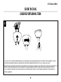
TOOLS REQUIRED
Phillips Screwdriver Wire Cutters Pliers Step Ladder
SAFETY TIPS
OBSERVE THE FOLLOWING: READ AND SAVE THESE INSTRUCTIONS
WARNING: TO REDUCE THE RISK OF FIRE, ELECTRIC SHOCK, OR PERSONAL INJURY, MOUNT TO OUTLET BOX MARKED 'ACCEPTABLE FOR FAN SUPPORT OF 35 LBS (15.9 KG) OR LESS'
AND USE MOUNTING SCREWS PROVIDED WITH THE OUTLET BOX AND/OR SUPPORT DIRECTLY FROM BUILDING STRUCTURE. MOST OUTLET BOXES COMMONLY USED FOR THE
SUPPORT OF LUMINARIES ARE NOT ACCEPTABLE FOR FAN SUPPORT AND MAY NEED TO BE REPLACED. CONSULT A QUALIFIED ELECTRICIAN IF IN DOUBT.

3
ETL-ES-Techno II-WH16
1. El trabajo de instalación y el cableado eléctrico los deben efectuar personas calificadas cumpliendo con todos los códigos y las normas aplicables (ANSI/NFPA 70), incluyendo las de incendio.
2. Use esta unidad sólo de la manera en que el fabricante quiere que se haga. Si tiene dudas, llame al fabricante.
3. Después de hacer las conexiones, empuje con cuidado las conexiones dentro de la caja de embutir con los conectores de cables mirando hacia arriba. Se deben separar los cables: el conductor de puesta a tierra y el conductor
de puesta a tierra del equipo a un lado de la caja de embutir, y el conductor que no tiene puesta a tierra del otro lado de la misma.
4. Antes de comenzar a instalar el ventilador, apague la alimentación en el panel de servicio y bloquee el medio de desconexión del servicio para evitar que se encienda accidentalmente. Cuando no se puede bloquear el medio
de desconexión del servicio eléctrico, fije de manera segura un dispositivo de advertencia prominente, como un rótulo, al panel de servicio.
5. ¡Tenga cuidado! Lea todas las instrucciones y la información de seguridad antes de instalar su ventilador nuevo. Revise los diagramas de montaje incluidos.
6. Al cortar o perforar una pared o techo, no dañe el cableado eléctrico y otras instalaciones de servicios públicos ocultos.
7. Asegúrese de que el sitio para la instalación que escoja permita que el ventilador gire libremente sin obstrucciones. Deje un espacio mínimo de 7 pies desde le piso hasta el borde posterior de la aleta.
8. Para reducir el riesgo de incendios, choques eléctricos o heridas personales, este ventilador se debe montar sobre una caja de embutir que tenga una marca que indique que es adecuada para soportar un ventilador.
Además debe utilizar los tornillos correspondientes incluidos con la caja de embutir. (El montaje debe soportar por lo menos 35 lbs. (15.9 kgs.).
9. ¡ADVERTENCIA! No doble los soportes para las aletas durante la instalación al motor, al balancear o durante la limpieza. No inserte objetos extraños entre las aletas mientras giran.
10. Fije el soporte de montaje usando sólo la tornillería suministrada con la caja de embutir. El ventilador sólo se debe montar en una caja de embutir marcada “Acceptable for Fan Support” (Aceptable para soportar ventiladores).
11. ¡ADVERTENCIA! Para reducir el riesgo de incendios o choques eléctricos, no use este ventilador con un dispositivo de control de velocidad de estado sólido para ventilador, o un control de velocidad variable.
12. Si esta unidad se instalará sobre una bañera o una ducha, debe estar identificada como adecuada para ese tipo de aplicación.
13. NUNCA coloque un interruptor donde se pueda alcanzar desde una bañera o una ducha.
14. Es posible que la operación de esta unidad afecte el flujo de aire de combustión necesario para la operación segura de equipo que quema combustible. Siga la directrices de seguridad del fabricante de equipo de calefacción
como las publicadas por la Asociación Nacional de Protección Contra Incendios (National Fire Protection Association, NFPA), y la Sociedad Americana para Ingenieros de Calefacción, Refrigeración y Aire Acondicionado
(American Society for Heating, Refrigeration and Air Conditioning Engineers, ASHRAE) y las autoridades del código local.
15. Antes de efectuar tareas de servicio o limpieza en la unidad, apague la alimentación en el panel de servicio y bloquee el medio de desconexión del servicio para evitar que se encienda accidentalmente. Cuando no se puede
bloquear el medio de desconexión del servicio eléctrico, fije de manera segura y un dispositivo de advertencia prominente, como un rótulo, al panel de servicio.
16. Antes de realizar la instalación, es importante comprobar y volver a ajustar todos los tornillos, según corresponda.
17. El dispositivo no ha sido diseñador para ser utilizado por niños o personas enfermas sin supervisión. Los niños deben ser supervisados para asegurarse de que no juegan con el dispositivo.
18. El artefacto luminoso tipo LED no contiene UV.
HERRAMIENTAS NECESARIAS
Destornillador Phillips Pinzas de corte Pinzas Escalera de mano
CONSEJOS DE SEGURIDAD
HAGA LO SIGUIENTE: LEA Y GUARDE ESTAS INSTRUCCIONES
ADVERTENCIA: PARA REDUCIR EL RIESGO DE INCENDIO, DESCARGA ELÉCTRICA O HERIDAS PERSONALES, MONTE EN UNA CAJA DE EMBUTIR ROTULADA “ADECUADA PARA VENTILADORES DE 35 LB (15,9 KGS )
O MENOS” UTILIZANDO LOS TORNILLOS DE MONTAJE INCLUIDOS CON LA CAJA DE EMBUTIR Y/O MONTE DIRECTAMENTE EN LA ESTRUCTURA DEL EDIFICIO. LA MAYORÍA DE LAS CAJAS DE EMBUTIR UTILIZADAS
NORMALMENTE CON ARTEFACTOS DE ILUMINACIÓN NO SON ADECUADAS PARA VENTILADORES Y DEBERÍAN SER REEMPLAZADAS. SI TIENE PREGUNTAS, CONSULTE A UN ELECTRICISTA CERTIFICADO.

4
ETL-ES-Techno II-WH16
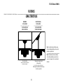
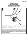
FEATURES
CARACTERÍSTICAS
VAULTED CEILING
INSTALLATION
INSTALACIÓN PARA
TECHOS INCLINADOS
DOWNROD
INSTALLATION
INSTALACIÓN CON
VARILLA VERTICAL
May require a longer downrod
(sold separately)
Podría requerir una varilla vertical más larga
(se vende por separado)
For normal ceilings
Para techos normales
Note: For pitched ceiling installation, please
refer to westinghouselighting.com for specially
designed canopy kit options.
Nota: Para instalación en techos inclinados,
visite westinghouselighting.com para obtener
opciones sobre equipos de dosel especialmente
diseñados.

5
ETL-ES-Techno II-WH16
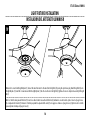
Unpack and inspect fan carefully to be certain all contents are included.
Turn off power at fuse box to avoid possible electrical shock.
1
Use metal outlet box suitable for fan support (must support 35 lbs).
Before attaching fan to outlet box, ensure the outlet box is securely
fastened by at least two points to a structural ceiling member (a loose
box will cause the fan to wobble).
2
PREPARING FOR INSTALLATION
ANTES DE LA INSTALACIÓN
Quite el envoltorio e inspeccione detenidamente el ventilador para verificar
que todas las piezas estén incluidas. Apague la alimentación en la caja de
fusibles para evitar la posibilidad de descarga eléctrica.
Use una caja de embutir de metal adecuada para soportar un ventilador
(debe soportar 35 libras). Antes de fijar el ventilador a la caja de embutir
asegúrese de que la misma esté fijada de manera segura en por lo menos
dos puntos a un miembro estructural del techo (una caja suelta haría
que el ventilador oscile).

6
ETL-ES-Techno II-WH16
Instale el soporte de montaje a la caja de embutir del techo con la
tornillería suministrada con la caja de embutir.
MOUNTING BRACKET INSTALLATION
INSTALACIÓN CON SOPORTE DE MONTAJE
3
4
MOUNTING OPTIONS
OPCIONES DE MONTAJE
Choose a MOUNTING OPTION
Elija una OPCIÓN DE MONTAJE
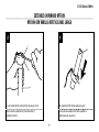
NORMAL DOWNROD OPTION
If installing downrod supplied with fan, proceed to page 7, step 5.
OPCIÓN CON VARILLA VERTICAL PARA TECHO NORMAL
Si instala la varilla vertical incluida con el ventilador,
proceda a la página 7, paso 5.
EXTENDED DOWNROD OPTION
If installing with longer downrod than supplied with fan, proceed to page 9, step 8.
OPCIÓN CON VARILLA VERTICAL MÁS LARGA
Si instala una varilla vertical más larga que la que se incluye con el
ventilador, proceda a la página 9, paso 8.
Install mounting bracket to outlet box in ceiling using the screws and
washers provided with the outlet box.

7
ETL-ES-Techno II-WH16
6
Place downrod assembly into canopy (1), canopy cover ring (2) and coupling cover (3).
Feed motor wires up through the bottom of the downrod assembly (4).
Coloque el conjunto de la varilla vertical (1) dentro del dosel (1), el anillo de la cubierta
del dosel (2) y la cubierta del acoplamiento (3). Pase los cables del motor del conjunto
de la varilla vertical (4).
2
1
3
4
Quite el pasador tipo prensa (1) desde el pasador transversal (2) de la vara (3).
5
Remove clamp pin (1) and cross pin (2) from downrod (3).
1
2
3
NORMAL DOWNROD OPTION
OPCIÓN CON VARILLA VERTICAL PARA TECHO NORMAL

8
ETL-ES-Techno II-WH16
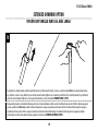
NORMAL DOWNROD OPTION
OPCIÓN CON VARILLA VERTICAL PARA TECHO NORMAL
Loosen set screws (1) in downrod coupling (2). Insert downrod into downrod coupling. Make sure to align hole in downrod with the hole in downrod coupling. Install coupling cross pin (3)
through coupling and downrod. Insert clamp pin (4) into cross pin until it snaps into place. Tighten set screws (1) in coupling. Slide coupling cover (5) over the downrod coupling. PROCEED
TO PAGE 11, STEP 11.
Afloje los tornillos de fijación (1) en el acoplador (2). Asegúrese de que el agujero de la varilla vertical y el del acoplamiento de la varilla vertical estén alineados. Instale el pasador
transversal (3) pasándolo por el acoplamiento y la varilla vertical. Inserte el pasador de fijación (4) en el pasador transversal hasta que escuche un chasquido que indique que está en la
posición adecuada. Ajuste los tornillos de fijación (1) en el acoplamiento. Deslice la cubierta del acoplamiento (5) sobre el acoplamiento de la varilla vertical. PROCEDE A LA PÀGINA 11,
PASO 11.
7
3
5
2
1
4

9
ETL-ES-Techno II-WH16
Loosen downrod ball (1) from downrod (2) by removing set screw (3).
Afloje la esfera de la varilla vertical (1) de la varilla vertical (2)
quitando el tornillo (3).
8
2
3
1
EXTENDED DOWNROD OPTION
OPCIÓN CON VARILLA VERTICAL MÁS LARGA
Slide downrod ball (1) off of downrod and remove pin (2).
Deslice la esfera de la varilla vertical (1) hasta separarla de la
varilla vertical y quite el pasador (2).
9
2
1

10
ETL-ES-Techno II-WH16
Re-install pin into extended downrod, and slide downrod ball up to the top of the downrod. Re-install set screw to secure ball to downrod. Note: Some extended downrods have
a pre-drilled set-screw hole. If a pre-drilled hole is present in the extended downrod, tighten the set screw into the pre-drilled hole in the extended downrod. If no pre-drilled hole
exists in the extended downrod, tighten the set screw against the downrod to secure the downrod ball. PROCEED TO PAGE 7, STEP 5.
Vuelva a instalar el pasador en la varilla vertical más larga y deslice la esfera de la varilla hasta el extremo superior de la misma. Vuelva a insertar el tornillo de fijación para asegurar
la esfera a la varilla vertical. Nota: Algunas varillas verticales más largas tienen un agujero previamente perforado para el tornillo. Si la varilla vertical más larga tiene un agujero
previamente perforado, ajuste el tornillo en el agujero previamente perforado de la varilla vertical más larga. Si la varilla vertical más larga no tiene un agujero previamente
perforado, ajuste el tornillo sobre la varilla vertical para asegurar la esfera de la misma. PROCEDE A LA PÀGINA 7, PASO 5.
EXTENDED DOWNROD OPTION
OPCIÓN CON VARILLA VERTICAL MÁS LARGA
10

11
ETL-ES-Techno II-WH16
11 12
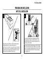
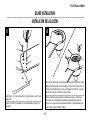
BLADE INSTALLATION
INSTALACIÓN DE LAS ALETAS
2
4
4
3
3
1
Attach blade (1) to the blade bracket (2) using the blade screws (3) and
washers (4)
Usando los tornillo (3) y arandelas (4) conecte las abrazaderas de aspa (2) a
las aspa (1).
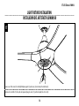
Place fan body with down rod pointing downward and motor positioned toward
ceiling. Attach the fan blade bracket assembly onto the motor, line up the holes in
the blade bracket with the holes in the motor (marked A-A, B-B. C-C), secure the
blade bracket to the motor with motor screws provided.
Volteas el ventilador par que la varilla este mirando hacia el piso y el motor hacia
el techo. Coloque el asemblaje de las abrazaderas de aletas al motor y alinea sus
agujeros con los agujeros del motor (marcado A-A, B-B, C-C), je las abrazaderas de
aletas al motor usando los tornillos incluidos.

12
ETL-ES-Techno II-WH16
Carefully lift fan assembly onto mounting bracket. Rotate fan until notch on downrod ball (1) engages the ridge on the mounting bracket (2). This will allow for hands free wiring.
Levante con cuidado el conjunto del ventilador hasta el soporte de montaje. Gire el ventilador hasta que la muesca de la bola de la varilla vertical (1) calce sobre la saliente del soporte
de montaje (2). De este modo, tendrá las dos manos libres para hacer el cableado.
MOUNTING
MONTAJE
13

13
ETL-ES-Techno II-WH16
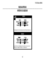
WIRING OPTIONS
OPCIÓN DE CABLEADO
14
Follow diagram above to make wiring connections for fan pull chain control.
WIRING
Siga las instrucciones del diagrama anterior para hacer las conexiones de
cableado para el ventilador controlado con cadenilla de tiro.
CABLEADO

14
ETL-ES-Techno II-WH16
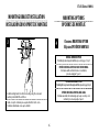
SECURE TO CEILING
ASEGURE EL VENTILADOR AL TECHO
Loosen the 2 screws on the bottom of mounting bracket. (do not remove) Raise the canopy up and align the keyholes on the bottom of the canopy with the 2 screws on
the bottom of mounting bracket. Rotate the canopy until both screws from the mounting bracket drop into the slot recesses. Tighten screws securely.
Afloje los 2 tornillos de la parte inferior del soporte de montaje (no los extraiga completamente). Suba el dosel y alinee las bocallaves de la parte inferior del dosel
con los 2 tornillos de la parte inferior del soporte de montaje. Gire el dosel hasta que ambos tornillos del soporte de montaje caigan dentro de las ranuras. Apriete los
tornillos asegurándolos.
15

15
ETL-ES-Techno II-WH16
16
The inside canopy cover ring (1) has two keyhole slots that allow it to be mounted onto the screw heads on the two protruding screws from the mounting bracket. Slide the canopy cover ring
up the downrod, and allow the two protruding screw heads from the mounting bracket to go into the keyhole slots on the canopy cover ring. Once engaged, twist the canopy cover ring to
lock it onto the screw heads. Note: Some adjustment of the screws from the mounting bracket may be necessary to allow the canopy cover ring to attach to the screw heads in the appropriate
manner:
1. Loosening of the screw heads may be necessary to allow the canopy cover ring to t onto the screws from the mounting bracket.
2. If the canopy is still loose after installing the canopy cover ring, the canopy cover ring may need to be removed and the mounting bracket screws tightened slightly to allow a more snug t
of the canopy, when the canopy cover ring is installed.
La cubierta interior para el anillo (1) del dosel tiene dos ranuras que permiten montarla en las cabezas de los dos tornillos que sobresalen del soporte de montaje. Deslice la cubierta el anillo
del escudete hacia arriba por la varilla y permita que las dos cabezas sobresalientes de los tornillos penetren en las ranuras de la cubierta del escudete. Una vez penentren, gire la cubierta del
escudete para trabar las cabezas de los tornillos en la parte más estrecha. Nota: Puede ser necesario ajustar los tornillos del soporte de montaje para permitir que la cubierta del escudete se
acople a las cabezas de los tornillos de manera apropiada.
1. Aoje los tornillos si es necesario para permitir que la cubierta del escudete pase sobre los tornillos del soporte de montaje.
2. Si el escudete aún está suelto después de instalar la cubierta el anillo del escudete, puede que sea necesario retirar la cubierta el anillo del escudete y apretar ligeramente los tornillos del
soporte de montaje para lograr un ajuste más preciso del escudete una vez instalada la cubierta el anillo del escudete.
1

16
ETL-ES-Techno II-WH16
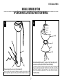
LIGHT FIXTURE INSTALLATION
INSTALACIÓN DEL ARTEFACTO LUMINOSO
Remove one of the screws (1) on the light kit plate support (3), and loosen, (do not remove) the other two (2).
Quite uno de los tornillos (1) del soporte de la placa del juego de luces (3) y suelte (sin quitar) los otros dos (2).
17
2
3
1

17
ETL-ES-Techno II-WH16
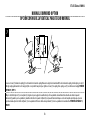
LIGHT FIXTURE INSTALLATION
INSTALACIÓN DEL ARTEFACTO LUMINOSO
Attach the light kit plate (2) to the light kit plate support (1) by placing the keyslot holes from the light kit plate onto the two protruding screw heads from the light kit plate
support. Twist the light kit plate clockwise until the screwheads engage the keyslots. Install the screw removed from light kit plate support (step#17) into the closed hole in
the light kit plate. Tighten all screws to complete attachment of the light kit plate.
Fije la placa del juego de luces (2) al soporte de la placa del juego de luces (1) colocando los agujero de chavetero de la placa del juego de luces en las dos cabezas de tornillo
sobresalientes del soporte de la placa del juego de luces. Gire la placa del juego de luces en dirección de las manecillas del reloj hasta que las cabezas de tornillo calcen con
los chaveteros. Instale el tornillo que quitó del soporte de la placa del juego de luces (paso 17) en el agujero cerrado de la placa del juego de luces. Apriete todos los tornillos
para poner fin a la fijación de la placa del juego de luces.
18
1
2

18
ETL-ES-Techno II-WH16
LIGHT FIXTURE INSTALLATION
INSTALACIÓN DEL ARTEFACTO LUMINOSO
Remove the 3 screws from the light kit plate (1). Connect the wires from motor to the wires from the light kit (2) by using the 2-pin molex plug. Attach the light kit (2) onto
the light kit plate (1). Install the 3 screws removed from the light kit plate (1) into the closed holes in the light kit (2).Tighten all screws to complete the assembly of the light
kit (2).
Quitelos3tornillosdelaplacadelkitdeluz(1).Conecteloscablesdelmotoraloscablesdelkitdeluz(2)medianteelconectormolexde2 pines.Conecteeljuegodeluces
(2)enlaplacadelkitde laluz(1).Instalarlos3tornillosquequitardelaplacadelkitde laluz(1)enlosagujeroscerradoseneljuegodeluces(2).Aprietetodoslostornillo
sparacompletarelmontajedeljuegodeluces(2).
19
1
2

19
ETL-ES-Techno II-WH16
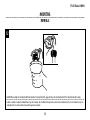
Locate the indentations on the neck of the glass and align with the protrusions on the inside of the light kit plate. Lift the glass up allowing the protrusions to engage the indentations of the
glass, and twist the glass clockwise to lock into place.
Localice las marcas en el cuello de la pantalla de vidrio y alinéelas con las protuberancias del la placa de juego de luces. Levante la pantalla permitiendo que las protuberancias calcen en las
marcas de la pantalla de vidrio y gire la pantalla en sentido horario para asegurarla en su sitio.
20
LIGHT FIXTURE INSTALLATION
INSTALACIÓN DEL ARTEFACTO LUMINOSO

20
ETL-ES-Techno II-WH16
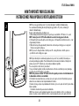
HOW TO OPERATE YOUR CEILING FAN
INSTRUCCIONES PARA OPERAR SU VENTILADOR DE TECHO
1
Restore electrical power to the outlet box by turning the electricity on at the main fuse box. To make the fan
operational, Open battery door by pressing down and sliding battery door down. Install one 23A 12V battery
(INCLUDED) into the hand-held remote transmitter (if not used for long periods of time, remove the battery to
prevent damage to the transmitter).
Note: Receiver in controllers system features an automatic learning function. There are no frequency switches
on the receiver unit. The receiver will automatically scan the frequency from the hand held control if any
changes are made, the frequency settings should be changed only in the case of interference or if multiple
ceiling fans with the same type of control system are installed in the same structure and are supposed to be
controlled separately. With fan power off, arrange code switches to the desired code setting. Then, turn the fan
power on, and follow the remote code setting process in Page 21. Store the remote away from excessive heat
or humidity.
Restablezca el suministro eléctrico de la caja de embutir conectando la alimentación eléctrica en la caja
principal de fusibles. Para que el ventilador funcione, abra el compartimiento de la pilas presionando y
deslizando hacia abajo. Coloque una pila 23A de 12 V (INCLUIDA) en el transmisor remoto de mano (en caso de
que no vaya a utilizar el artefacto durante un período de tiempo prolongado, extraiga la pila para evitar dañar
el transmisor).
Nota: El receptor del sistema de controladores incluye una función de aprendizaje automático. No hay
interruptores de frecuencia en la unidad del receptor. En caso de que se realice algún cambio, el receptor leerá
automáticamente la frecuencia del control de mano. Los ajustes de frecuencia deben cambiarse solo en caso
de interferencia o si múltiples ventiladores de techo con el mismo tipo de sistema de control se instalan en la
misma estructura y se desea controlarlos por separado. Con el ventilador apagado, disponga los interruptores
de código según el ajuste de código deseado. Luego apague el ventilador y siga el proceso para ajustar el
código del control remoto en la página 21. Guarde el control remoto en un lugar protegido contra el calor o la
humedad excesivos.
1
3
0
SET

21
ETL-ES-Techno II-WH16
HOW TO OPERATE YOUR CEILING FAN
INSTRUCCIONES PARA OPERAR SU VENTILADOR DE TECHO
2
NOTE: There is a toggle switch preset at "on" position indicating it's suitable for dimmable lamps.
You can eliminate the dimming function by sliding the toggle switch to "D" position , indicating it's
suitable for dimmable lamps.
Remote control setting and speed setting process:
1) After installing the unit and restoring power to your fan, press and hold the "SET" button 1~5 seconds.
NOTE: You must press the "SET" button within 60 seconds of restoring power to the fan.
2) The fan will start to run and begin the control setting process. The fan will run in both directions for a total
of approximately 5 minutes.
3) When the fan stops after approximately 5 minutes the control and speed setting process is completed.
The fan is now ready for normal use.
NOTE: If you need to change the blades: turn the power off ->change the blades->turn the power on
->perform the control setting process again.
NOTA: Hay un interruptor de conmutación preajustado en la posición "on (encendido)" indicando que es
adecuado para lámparas regulables. Puede eliminar la función de atenuación deslizando el interruptor de
palanca a la posición "D", indicando que es adecuado para lámparas regulables.
Proceso de ajuste del control remoto y la velocidad:
1) Luego de instalar la unidad y restablecer la alimentación eléctrica de su ventilador, presione y mantenga
presionado el botón "SET" durante 1 a 5 segundos.
NOTA: Debe presionar el botón "SET" dentro de los 60 segundos posteriores al restablecimiento de
la alimentación eléctrica de su ventilador.
2) El ventilador comenzará a funcionar y se iniciará el proceso de ajuste del control. El ventilador operará en
ambas direcciones durante un total de aproximadamente 5 minutos.
3) Cuando se detenga, después de aproximadamente 5 minutos, el proceso de ajuste del control y la velocidad se
habrá completado.
El ventilador está ahora listo para ser usado normalmente.
NOTA: En caso de que necesite reemplazar las paletas: desconecte el suministro eléctrico-> reemplace las
paletas-> vuelva a conectar el suministro eléctrico->realice nuevamente el proceso de ajuste del control.
1
3
0
SET
ON
D
ON ECE
1
2 3 4
ON
D

22
ETL-ES-Techno II-WH16
HOW TO OPERATE YOUR CEILING FAN
INSTRUCCIONES PARA OPERAR SU VENTILADOR DE TECHO
3
1
3
0
III
L H
IV
V
II
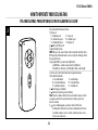
The remote buttons function as follows:
(1) Fan speed:
L = minimum speed II = low speed
III = medium low speed IV = medium speed
V = medium high speed H = high speed
(2) Button: Turn the fan off
(3) Control fan direction
NOTE: When press the reverse button on the remote will result in the motor
first being turned off and allowed to coast to a stop before starting to turn in
the opposite direction.
(4) -Light On/Off – press and release light button.
-Light Dimmer - continuous pressure on the light button
dims light in a continuous cycle from light to dark, or dark to light.
Los botones del control remoto funcionan de la siguiente manera:
1) Velocidad del ventilador:
L = velocidad mínima II = velocidad baja
III = velocidad media baja IV = velocidad media
V = velocidad media alta H = velocidad alta
2) Botón: Apagar el ventilador
3) Controlar el sentido de giro del ventilador
Nota: Cuando se oprima el botón de reversa el resultado sería que el motor
se apagara y suavemente se parara antes de que empiece a girar en la
dirección contraria.
4) -Luz encendida/apagada –presionar y soltar el butón de luz.
-Conmutador de intensidad - al presionar continuamente el botón de
luz, última comuta en un ciclo continuo de más claro a más oscuro o
de más oscuro a más claro.

23
ETL-ES-Techno II-WH16
HOW TO REPLACE YOUR RECEIVER
CÓMO REEMPLAZAR SU RECEPTOR
1
3
4
2
1
2
Take down the fan and take off the down rod assembly by removing the cross pin with clamp pin and unloosing the 2 fixing screws (1) from the down rod coupling (2). Lift
away the upper motor housing (3) and the enhancing metal washer (5) off the down rod coupling (2) after unscrewing the six fixing screws (4), save six screws for future
usage.
Desmontarelventiladorysacarlavarillahacia abajoquitandoelpernocruzadoconelpernode laabrazaderayaflojandolos2tornillos(1)defijacióndelavarillahacia aba
jodelacoplamiento(2).Levantealacubiertasuperiordelmotor(3)ylaarandelademetalaumento(5)lavarillahacia abajodelacoplamiento(2)despuésdelosseistornill
osdefijación(4),exceptoseistornillosparausofuturo.
5

24
ETL-ES-Techno II-WH16
HOW TO REPLACE YOUR RECEIVER
CÓMO REEMPLAZAR SU RECEPTOR
2
Remove the wire clip (1) by unloosening the screw, and remove the 2 fixing screws (2) at each end of receiver box (3), save them for future usage, remove the grounding
wire (4) from the plate by unscrew the screw, then unplug the 9-pin wire connectors (5) between receiver box (3) and motor. Take away the old receiver and replace with
a new one.
Quite los ganchos para cable (1) aflojando los tornillos correspondientes y saque los 2 tornillos de fijación (2) ubicados en cada extremo de la caja del receptor (3).
Resérvelos para su uso posterior. Quite el cable a tierra (4) de la placa aflojando el tornillo y, luego, desenchufe los conectores para cables de 9 pines (5) que se
encuentran entre la caja del receptor (3) y el motor. Saque el receptor viejo y coloque uno nuevo.
5
2
3
2
1
4

25
ETL-ES-Techno II-WH16
3
Fix the new receiver box (1) on to the receiver support plate (2) by using the 2 fixing screws (3) removed in step#2, tighten them securely; Use the wire clip (4) and screw
(5) removed in step#2 to secure the wire, screw the grounding wire (6) from the new receiver onto the metal plate securely. Connect the 9-way plug (7) from the new
receiver to the ones from the motor.
Fije la nueva caja para el receptor (1) a la placa de soporte del receptor (2) utilizando los 2 tornillos de fijación (3) que extrajo en el paso 2; 3. Utilice el gancho para
cables (4) y el tornillo (5) que extrajo en el paso 2 para asegurar el cable, atornille el cable a tierra (6) del receptor nuevo en la placa de metal para asegurarlo. Conecte el
conector de 9 pines (7) del receptor nuevo a los del motor.
1
2
3
4
6
7
5

26
ETL-ES-Techno II-WH16
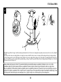
4
Reinstall the upper Motor housing (1) and the enhancing metal washer (2) onto the down rod coupling (4) by using the previously removed six screws (3), and tighten
securely.
Insert down rod into down rod coupling. Make sure to align hole in down rod with the hole in down rod coupling. Install coupling pin through coupling and down
rod. Insert clamp pin into cross pin until it snaps into place. Tighten set screws in coupling. Slide coupling cover over the down rod coupling. Repeat from Step #13 in
Page 12 to step#16 in page 15 to complete the fan assembly. then go to Page 21 step#2 to repeat the "Remote Control Setting And Speed Setting Process" . after that,
the new receiver box is ready for use.
Vuelva a instalarlacubiertasuperiordelmotor(1)ylaarandelademetalmejorarenlavarillahacia abajodeacoplamiento(2)medianteelusodelosseistornillos
quehabíamosquitados(3)yaprietehacia abajolabarraenaacoplamientode labarra.Asegúresedealinearelagujerohacia abajode labarraconelagujerohacia
abajodeacoplamientode labarra.Instaleelpasadordeacoplamientoa travésdeacoplamientoylabarra.Inserteelpasadordesujeciónencruzpinhastaqueencajeensul
ugar.Aprietelos tornillosdeacoplamiento.Desliceelrepetirdelpaso #13enpágina #12apaso #16enpágina #15paracompletarelensamblajedelventilador.luegoiralpa
so #2pararepetirel"Controlremotoajustedevelocidadajusteprocesoy",página21.despuésdeeso,lanuevacajadelreceptorestálistaparausar.
3
1
2
4

27
ETL-ES-Techno II-WH16
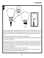
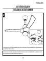
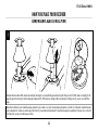
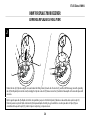
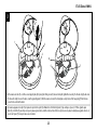
OPERATION & MAINTENANCE
Operation
Turn on the power and check operation of fan.
Speed settings for warm or cool weather depend on factors such as room size, ceiling height, number of fans and so on.
The reverse switch in remote transmitter controls direction, forward or reverse.
Warm weather/down position - (Forward) Fan turns counterclockwise direction. A downward air flow creates a cooling effect as shown in illustration A.
This allows you to set your air conditioner on a higher temperature setting without affecting your comfort.
Cool weather/up position - (Reverse) Fan turns clockwise direction. An upward airflow moves warm air off the ceiling area as shown in illustration B.
This allows you to set your heating unit on a lower setting without affecting your comfort.
Maintenance
1. Because of the fan’s natural movement, some connections may become loose. Check the support connections, brackets, and blade
attachments twice a year. Make sure they are secure.
2. Clean your fan periodically to help maintain its new appearance over the years. Do not use water when cleaning. This could damage
the motor, or the wood, or possibly cause electrical shock.
3. Use only a soft brush or lint-free cloth to avoid scratching the finish. The plating is sealed with a lacquer coating to minimize
discoloration or tarnishing.
4. There is no need to oil your fan. The motor has permanently lubricated bearings.

28
ETL-ES-Techno II-WH16
OPERACIÓN Y MANTENIMIENTO
Operación
Encienda el ventilador y verifique su funcionamiento.
Las velocidades para clima cálido o frío dependen de factores como el tamaño de la habitación, la altura del ventilador, el número de ventiladores, etc.
El interruptor de marcha atrás del transmisor remoto controla la dirección, ya sea marcha adelante o marcha atrás.
Clima cálido/posición hacia abajo - (Adelante) El ventilador gira en sentido contrahorario. Una corriente de aire descendente crea un efecto refrescante
como lo indica la ilustración A.
Esto le permite ajustar el aire acondicionado a una temperatura más alta sin que afecte su comodidad.
Clima frío/posición hacia arriba - (Atrás) El ventilador gira en sentido de las agujas del reloj. Una corriente de aire ascendente aleja el aire caliente
del área del ventilador de techo como lo indica la ilustración B. Esto le permite ajustar la calefacción a un nivel más bajo sin que afecte su comodidad.
Mantenimiento
1. El movimiento natural del ventilador podría hacer que se aflojen algunas conexiones. Verifique las conexiones de soporte, las piezas
de fijación y los accesorios de las paletas dos veces al año. Cerciórese de que estén aseguradas.
2. Limpie el ventilador periódicamente para ayudar a mantener su apariencia nueva con el correr de los años. No use agua para
limpiarlo, ya que podría dañar el motor o la madera o causar descarga eléctrica.
3. Use sólo un cepillo blando o un trapo sin pelusa para no rayar el acabado. El enchapado está sellado con una capa de laca para
minimizar la decoloración o pérdida del brillo.
4. No hay necesidad de aceitar el ventilador. El motor tiene cojinetes de lubricación permanente.

29
ETL-ES-Techno II-WH16
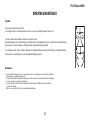
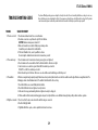
TROUBLE
TROUBLESHOOTING GUIDE
If you have difficulty operating your new ceiling fan, it may be the result of incorrect assembly, installation, or wiring. In some cases,
these installation errors may be mistaken for defects. If you experience any faults, please check this trouble shooting chart. If a problem
cannot be remedied, please consult with your authorized electrician and do not attempt any electrical repairs yourself.
1. If fan does not start: 1. Check main and branch circuit fuses or circuit breakers.
2. Check wire connections as performed in step #14 of installation.
CAUTION: Make sure main power is turned off.
3. Make sure forward/reverse switch is firmly in up or down position.
Fan will not operate when switch is in the middle.
4. If the fan still will not start, contact a qualified electrician.
Do not attempt to troubleshoot internal electrical connections yourself.
2. If fan sounds noisy: 1. Check to make sure all screws in motor housing are snug (not over tightened).
2. Check to make sure the screws which attach the fan blade holder to the motor are tight.
3. Some fan motors are sensitive to signals from Solid State variable speed controls.
DO NOT USe a Solid State variable speed control.
4. Allow “break-in” period of 24 hours. Most noises associated with a new fan will disappear after this period.
3. If fan wobbles: All blades are weighed and grouped by weight. Natural woods vary in density which could cause the fan to wobble even though all blades are weight-matched. The
following procedures should eliminate most of the wobble. Check for wobble after each step.
1. Check that all blades are screwed firmly into blade holders.
2. Check that all blade holders are tightened securely to motor.
3. Make sure that canopy and mounting bracket are tightened securely to ceiling joist.
4. If blade wobble is still noticeable, interchanging two adjacent (side by side) blades can redistribute the weight and possibly result in smoother operation.
4. If light does not work: 1. Check to see that the wire connections in the switch housing are connected.
2. Check for faulty light bulbs.
3. If light kit will still not operate, contact a qualified electrician for assistance.
SUGGESTED REMEDY

30
ETL-ES-Techno II-WH16
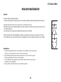
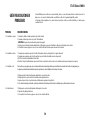
GUÍA PARA SOLUCIONAR
PROBLEMAS
Si tiene dificultades para hacer funcionar su nuevo ventilador, podría ser a causa del armado, instalación o cableado incorrectos. En
algunos casos, estos errores de instalación podrían ser confundidos con defectos. Si experimenta alguna falla, consulte
esta guía para solucionar problemas. Si no puede solucionar el problema, consulte a un electricista calificado y no intente reparar
conexiones eléctricas.
PROBLEMA
1. Si el ventilador no arranca:
2. Si el ventilador es ruidoso:
3. Si el ventilador oscila:
4. Si la luz no funciona:
SOLUCIÓN SUGERIDA
1. Compruebe los fusibles o disyuntores principales y del circuito derivado.
2. Compruebe el cableado que se hizo en el paso No. 14 de la instalación.
ADVERTENCIA: Asegúrese de que la alimentación principal esté apagada.
3. Asegúrese de que el interruptor de marcha adelante/atrás esté firmemente en su posición. El ventilador no funcionará si el interruptor está en el medio.
4. Si el ventilador no arranca, póngase en contacto con un electricista calificado. No intente reparar conexiones eléctricas internas.
1. Compruebe para asegurarse de que todos los tornillos del alojamiento del motor estén ajustados (no los apriete demasiado).
2. Compruebe para asegurarse de que los tornillos que fijan el soporte de la aleta del ventilador al motor estén apretados.
3. NO USE un control de velocidad variable de estado sólido.
4. Permita el "rodaje" del ventilador durante un período de 24 horas. La mayoría de los ruidos asociados con el ventilador nuevo desaparecerán después de este período.
Todas las aletas se pesan y agrupan según el peso. Las maderas naturales varían en densidad y podrían hacer que el ventilador oscile aún cuando todas las aletas estén agrupadas por peso.
Los siguientes procedimientos deberían eliminar la mayoría de los problemas de oscilación. Verifique la oscilación después de cada paso.
1. Verifique que todas las aletas estén firmemente atornilladas a los soportes de las aletas.
2. Verifique que todos los soportes de las aletas estén firmemente aseguradas al motor.
3. Asegúrese de que el dosel y el soporte de montaje estén firmemente asegurados a la viga del techo.
4. Si la oscilación de la aleta sigue siendo visible, es posible que al intercambiar dos aletas adyacentes (lado a lado) se redistribuya el peso y el funcionamiento sea más suave.
1. Verifique que el conector molex del alojamiento del interruptor esté conectado.
2. Compruebe si hay lámparas defectuosas.
3. Si el conjunto de luces no funciona, póngase en contacto con un electricista calificado.

31
ETL-ES-Techno II-WH16
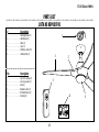
PARTS LIST
LISTA DE REPUESTOS
# Description
1. . . . . . . . . . . . . . . . . . . . . . Mounting Bracket (1)
2. . . . . . . . . . . . . . . . . . . . . . Blade Bracket (3)
3. . . . . . . . . . . . . . . . . . . . . . Blade (3)
4. . . . . . . . . . . . . . . . . . . . . . Glass (1)
5. . . . . . . . . . . . . . . . . . . . . . DC Remote Control (1)
6. . . . . . . . . . . . . . . . . . . . . . Hardware Pack (1)
No. Descripción
1. . . . . . . . . . . . . . . . . . . . . .Soporte de montaje (1)
2. . . . . . . . . . . . . . . . . . . . . .Soporte para aleta (3)
3. . . . . . . . . . . . . . . . . . . . . .Aleta (3)
4. . . . . . . . . . . . . . . . . . . . . .Pantalla de vidrio (1)
5. . . . . . . . . . . . . . . . . . . . . .DC Control Remoto (1)
6. . . . . . . . . . . . . . . . . . . . . .Tornillería (1)
6
5
2
3
4
1
1
3
0
III
L H
IV
V
II

Westinghouse Lighting, Philadelphia, PA 19154-1029, U.S.A.
www.westinghouselighting.com
, WESTINGHOUSE, and INNOVATION YOU CAN BE SURE OF
are trademarks of Westinghouse Electric Corporation.
Used under license by Westinghouse Lighting
All rights reserved.
Made in China
ETL-ES-Techno II-WH16
-
 1
1
-
 2
2
-
 3
3
-
 4
4
-
 5
5
-
 6
6
-
 7
7
-
 8
8
-
 9
9
-
 10
10
-
 11
11
-
 12
12
-
 13
13
-
 14
14
-
 15
15
-
 16
16
-
 17
17
-
 18
18
-
 19
19
-
 20
20
-
 21
21
-
 22
22
-
 23
23
-
 24
24
-
 25
25
-
 26
26
-
 27
27
-
 28
28
-
 29
29
-
 30
30
-
 31
31
-
 32
32


Westinghouse 7204200 El manual del propietario
- Categoría
- Ventiladores domésticos
- Tipo
- El manual del propietario
en otros idiomas
- English: Westinghouse 7204200 Owner's manual
Artículos relacionados
-
Westinghouse 7727000 El manual del propietario
-
Westinghouse Zander El manual del propietario
-
-
-
-
-
Westinghouse 52-inch Manual de usuario
-
-
-
