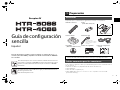
Yamaha HTR-4066 Guía de instalación
- Categoría
- Receptores AV
- Tipo
- Guía de instalación
Este manual también es adecuado para
Yamaha HTR-4066: experimenta la magia del sonido envolvente con este increíble receptor AV de 5.1 canales. Disfruta de un audio claro y potente con una potencia de salida de 100 vatios por canal (6 ohmios, 1 kHz, 1% THD), siente cada detalle con la tecnología de decodificación de sonido envolvente Dolby Digital y DTS, y sumérgete en tus películas y programas de televisión favoritos con la compatibilidad con vídeo 4K Ultra HD y HDR.
Yamaha HTR-4066: experimenta la magia del sonido envolvente con este increíble receptor AV de 5.1 canales. Disfruta de un audio claro y potente con una potencia de salida de 100 vatios por canal (6 ohmios, 1 kHz, 1% THD), siente cada detalle con la tecnología de decodificación de sonido envolvente Dolby Digital y DTS, y sumérgete en tus películas y programas de televisión favoritos con la compatibilidad con vídeo 4K Ultra HD y HDR.


-
 1
1
-
 2
2
-
 3
3
-
 4
4
-
 5
5
-
 6
6
-
 7
7
-
 8
8
-
 9
9
-
 10
10
-
 11
11
-
 12
12
-
 13
13
-
 14
14
-
 15
15
-
 16
16
-
 17
17
-
 18
18


Yamaha HTR-4066 Guía de instalación
- Categoría
- Receptores AV
- Tipo
- Guía de instalación
- Este manual también es adecuado para
Yamaha HTR-4066: experimenta la magia del sonido envolvente con este increíble receptor AV de 5.1 canales. Disfruta de un audio claro y potente con una potencia de salida de 100 vatios por canal (6 ohmios, 1 kHz, 1% THD), siente cada detalle con la tecnología de decodificación de sonido envolvente Dolby Digital y DTS, y sumérgete en tus películas y programas de televisión favoritos con la compatibilidad con vídeo 4K Ultra HD y HDR.
en otros idiomas
- English: Yamaha HTR-4066 Installation guide
Artículos relacionados
-
Yamaha HTR-3065 Guía de instalación
-
Yamaha RX-V575 El manual del propietario
-
Yamaha HTR-3066 El manual del propietario
-
-
Yamaha HTR-4066 El manual del propietario
-
Yamaha RX-A830 Guía de instalación
-
Yamaha RX-V375 El manual del propietario
-
-
Yamaha RX-A730 El manual del propietario
-
Yamaha RX-V677 El manual del propietario