Yamaha EMX5 El manual del propietario
- Categoría
- Amplificadores de audio
- Tipo
- El manual del propietario


2
EMX5 Owner’s Manual
The above warning is located on the rear of the unit.
L’avertissement ci-dessus est situé sur l’arrière de l’unité.
Explanation of Graphical Symbols
Explication des symboles
The lightning flash with arrowhead symbol within an equilateral triangle is intended to alert
the user to the presence of uninsulated “dangerous voltage” within the product’s enclosure that
may be of sufficient magnitude to constitute a risk of electric shock to persons.
L’éclair avec une flèche à l’intérieur d’un triangle équilatéral est destiné à attirer l’attention de
l’utilisateur sur la présence d’une « tension dangereuse » non isolée à l’intérieur de l’appareil,
pouvant être suffisamment élevée pour constituer un risque d’électrocution.
The exclamation point within an equilateral triangle is intended to alert the user to the pres-
ence of important operating and maintenance (servicing) instructions in the literature accom-
panying the product.
Le point d’exclamation à l’intérieur d’un triangle équilatéral est destiné à attirer l’attention de
l’utilisateur sur la présence d’instructions importantes sur l’emploi ou la maintenance (réparat-
ion) de l’appareil dans la documentation fournie.
IMPORTANT SAFETY INSTRUCTIONS
1 Read these instructions.
2 Keep these instructions.
3 Heed all warnings.
4 Follow all instructions.
5 Do not use this apparatus near water.
6 Clean only with dry cloth.
7 Do not block any ventilation openings. Install in accordance with the manufacturer’s instructions.
8 Do not install near any heat sources such as radiators, heat registers, stoves, or other apparatus (includ-
ing amplifiers) that produce heat.
9 Do not defeat the safety purpose of the polarized or grounding-type plug. A polarized plug has two blades
with one wider than the other. A grounding type plug has two blades and a third grounding prong. The
wide blade or the third prong are provided for your safety. If the provided plug does not fit into your outlet,
consult an electrician for replacement of the obsolete outlet.
10 Protect the power cord from being walked on or pinched particularly at plugs, convenience receptacles,
and the point where they exit from the apparatus.
11 Only use attachments/accessories specified by the manufacturer.
12 Use only with the cart, stand, tripod, bracket, or table specified by the manufacturer,
or sold with the apparatus. When a cart is used, use caution when moving the cart/
apparatus combination to avoid injury from tip-over.
13 Unplug this apparatus during lightning storms or when unused for long periods of
time.
14 Refer all servicing to qualified service personnel. Servicing is required when the
apparatus has been damaged in any way, such as power-supply cord or plug is dam-
aged, liquid has been spilled or objects have fallen into the apparatus, the apparatus has been exposed to
rain or moisture, does not operate normally, or has been dropped.
(UL60065_03)
PRÉCAUTIONS CONCERNANT LA SÉCURITÉ
1 Lire ces instructions.
2 Conserver ces instructions.
3 Tenir compte de tous les avertissements.
4 Suivre toutes les instructions.
5 Ne pas utiliser ce produit à proximité d’eau.
6 Nettoyer uniquement avec un chiffon propre et sec.
7 Ne pas bloquer les orifices de ventilation. Installer l’appareil conformément aux instructions du fabricant.
8 Ne pas installer l’appareil à proximité d’une source de chaleur comme un radiateur, une bouche de cha-
leur, un poêle ou tout autre appareil (y compris un amplificateur) produisant de la chaleur.
9 Ne pas modifier le système de sécurité de la fiche polarisée ou de la fiche de terre. Une fiche polarisée dis-
pose de deux broches dont une est plus large que l’autre. Une fiche de terre dispose de deux broches et
d’une troisième pour le raccordement à la terre. Cette broche plus large ou cette troisième broche est des-
tinée à assurer la sécurité de l’utilisateur. Si la fiche équipant l’appareil n’est pas compatible avec les pri-
ses de courant disponibles, faire remplacer les prises par un électricien.
10 Acheminer les cordons d’alimentation de sorte qu’ils ne soient pas piétinés ni coincés, en faisant tout
spécialement attention aux fiches, prises de courant et au point de sortie de l’appareil.
11 Utiliser exclusivement les fixations et accessoires spécifiés par le fabricant.
12 Utiliser exclusivement le chariot, le stand, le trépied, le support ou la table recom-
mandés par le fabricant ou vendus avec cet appareil. Si l’appareil est posé sur un
chariot, déplacer le chariot avec précaution pour éviter tout risque de chute et de
blessure.
13 Débrancher l’appareil en cas d’orage ou lorsqu’il doit rester hors service pendant
une période prolongée.
14 Confier toute réparation à un personnel qualifié. Faire réparer l’appareil s’il a subi
tout dommage, par exemple si la fiche ou le cordon d’alimentation est endommagé, si du liquide a coulé
ou des objets sont tombés à l’intérieur de l’appareil, si l’appareil a été exposé à la pluie ou à de l’humidité,
si l’appareil ne fonctionne pas normalement ou est tombé.
(UL60065_03)
WARNING
TO REDUCE THE RISK OF FIRE OR ELECTRIC SHOCK, DO NOT EXPOSE THIS APPARATUS TO RAIN OR
MOISTURE.
AVERTISSEMENT
POUR RÉDUIRE LES RISQUES D’INCENDIE OU DE DÉCHARGE ÉLECTRIQUE, N’EXPOSEZ PAS CET
APPAREIL À LA PLUIE OU À L’HUMIDITÉ.

3
EMX5 Owner’s Manual
PRECAUTIONS
PLEASE READ CAREFULLY
BEFORE PROCEEDING
Please keep this manual in a safe place for
future reference.
WARNING
Always follow the basic precautions listed below to
avoid the possibility of serious injury or even death
from electrical shock, short-circuiting, damages, fire
or other hazards. These precautions include, but are
not limited to, the following:
Power supply/power cord
• Do not place the power cord near heat sources such as
heaters or radiators, and do not excessively bend or
otherwise damage the cord, place heavy objects on it, or
place it in a position where anyone could walk on, trip
over, or roll anything over it.
• Only use the voltage specified as correct for the device.
The required voltage is printed on the name plate of the
device.
• Use only the supplied power cord/plug.
If you intend to use the device in an area other than in the
one you purchased, the included power cord may not be
compatible. Please check with your Yamaha dealer.
• Check the electric plug and each jack periodically, and
remove any dirt or dust which may have accumulated.
Failure to do so may cause electrical shock, short-
circuiting or fire.
• When setting up the device, make sure that the AC outlet
you are using is easily accessible. If some trouble or
malfunction occurs, immediately turn off the power switch
and disconnect the plug from the outlet. Even when the
power switch is turned off, as long as the power cord is not
unplugged from the wall AC outlet, the device will not be
disconnected from the power source.
• Remove the electric plug from the outlet when the device
is not to be used for extended periods of time, or during
electrical storms.
• Be sure to connect to an appropriate outlet with a
protective grounding connection.
Do not open
• This device contains no user-serviceable parts. Do not
open the device or attempt to disassemble the internal
parts or modify them in any way. If it should appear to be
malfunctioning, discontinue use immediately and have it
inspected by qualified Yamaha service personnel.
Water warning
• Do not expose the device to rain, use it near water or in
damp or wet conditions, or place on it any containers
(such as vases, bottles or glasses) containing liquids
which might spill into any openings. If any liquid such as
water seeps into the device, turn off the power
immediately and unplug the power cord from the AC
outlet. Then have the device inspected by qualified
Yamaha service personnel.
• Never insert or remove an electric plug with wet hands.
Hearing loss
• Avoid setting all equalizer and level controls to their
maximum. Depending on the condition of the connected
devices, doing so may result in feedback that can cause
hearing loss and damage the speakers.
• Do not use speakers for a long period of time at a high or
uncomfortable volume level, since this can cause
permanent hearing loss. If you experience any hearing
loss or ringing in the ears, consult a physician.
• When turning on the AC power in your audio system,
always turn on the device LAST, to avoid hearing loss and
speaker damage. When turning the power off, the device
should be turned off FIRST for the same reason.
Fire warning
• Do not place any burning items or open flames near the
device, since they may cause a fire.
If you notice any abnormality
• If any of the following problems occur, immediately turn off
the power switch and disconnect the electric plug from the
outlet.
- The power cord or plug becomes frayed or damaged.
- Unusual smells or smoke are emitted.
- Some object has been dropped into the device.
- There is a sudden loss of sound during use of the device.
- Cracks or other visible damage appear on the device.
Then have the device inspected or repaired by qualified
Yamaha service personnel.
• If this device should be dropped or damaged,
immediately turn off the power switch, disconnect the
electric plug from the outlet, and have the device
inspected by qualified Yamaha service personnel.
CAUTION
Always follow the basic precautions listed below to
avoid the possibility of physical injury to you or
others, or damage to the device or other property.
These precautions include, but are not limited to, the
following:
Power supply/power cord
• When removing the electric plug from the device or an
outlet, always hold the plug itself and not the cord. Pulling
by the cord can damage it.
Location
• Do not place the device in an unstable position where it
might accidentally fall over and cause injuries.
• Do not block the vents. This device has ventilation holes at
the sides to prevent the internal temperature from
becoming too high. In particular, do not place the device
on its side or upside down. Inadequate ventilation can
result in overheating, possibly causing damage to the
device(s), or even fire.
• When using the device:
- Do not cover it with any cloth.
- Do not install it on a carpet or rug.
- Do not use the device in a confined, poorly-ventilated
location.
Inadequate ventilation can result in overheating, possibly
causing damage to the device(s), or even fire. If this
device is to be used in a small space other than an EIA-
standard rack, make sure that there is adequate space
around the device: at least 30 cm above, 30 cm at the
sides and 30 cm behind.
• Do not place the device in a location where it may come
into contact with corrosive gases or salt air. Doing so may
result in malfunction.
• Before moving the device, remove all connected cables.
• If the device is mounted in an EIA standard rack, carefully
read the section “Precautions for Rack Mounting” on page
16. Inadequate ventilation can result in overheating, possibly
causing damage to the device(s), malfunction, or even fire.
PA_en_7 1/2

4
EMX5 Owner’s Manual
Connections
• Do not use speaker cables with a metal-housing
connector. Doing so may result in electrical shock due to
differences in voltage. Use speaker cables with a
nonmetal-housing connector, or with a insulated-housing
connector.
• Before connecting the device to other devices, turn off the
power for all devices. Also, before turning the power of all
devices on or off, make sure that all volume levels are set
to the minimum. Failing to do so may result in electric
shock or equipment damage.
• Use only speaker cables for connecting speakers to the
speaker jacks. Use of other types of cables may result in
fire.
Maintenance
• Remove the power plug from the AC outlet when cleaning
the device.
Handling caution
• Avoid inserting or dropping foreign objects (paper, plastic,
metal, etc.) into any gaps or openings on the device
(vents, panel, etc.). If this happens, immediately turn off
the power, unplug the power cord from the AC outlet, and
have the device inspected by qualified Yamaha service
personnel.
• Do not rest your weight on the device or place heavy
objects on it. Avoid applying excessive force to the
buttons, switches or connectors to prevent injuries.
Yamaha cannot be held responsible for damage caused
by improper use or modifications to the device.
NOTICE
To avoid the possibility of malfunction/ damage to the
product, damage to data, or damage to other property, fol-
low the notices below.
Handling and maintenance
• Do not use the device in the vicinity of a TV, radio, AV
equipment, mobile phone, or other electric devices. Oth-
erwise, the device, TV, or radio may generate noise.
• Do not expose the device to excessive dust or vibration,
or extreme cold or heat (such as in direct sunlight, near
a heater, or in a car during the day), in order to prevent
the possibility of panel disfiguration, unstable operation,
or damage to the internal components.
• Do not place vinyl, plastic or rubber objects on the
device, since this might discolor the panel.
• Place input cables for devices such as microphones,
and microphone amplifier circuits with high sensitivity in
a location that is far away from the speaker cables. In
addition, ensure that the power cord is kept at least 1 cm
from the speaker cables. Due to an excessively large
current flowing through the speaker cables, it may lead
to acoustic noise or electromagnetic interference.
• When cleaning the device, use a dry and soft cloth. Do
not use paint thinners, solvents, cleaning fluids, or
chemical-impregnated wiping cloths.
• Condensation can occur in the device due to rapid, dras-
tic changes in ambient temperature—when the device is
moved from one location to another, or air conditioning
is turned on or off, for example. Using the device while
condensation is present can cause damage. If there is
reason to believe that condensation might have
occurred, leave the device for several hours without turn-
ing on the power until the condensation has completely
dried out.
• Do not use the output of this device for any purpose
other than driving loudspeakers.
• Always turn the power off when the device is not in use.
Connectors
• XLR-type connectors are wired as follows (IEC60268
standard): pin 1: ground, pin 2: hot (+), and pin 3: cold (-).
• Use only Neutrik NL4 plugs for connecting speakON
connectors.
Information
About this manual
• The illustrations and LCD screens as shown in this man-
ual are for instructional purposes only.
• The company names and product names in this manual
are the trademarks or registered trademarks of their
respective companies.
• European models
Purchaser/User Information specified in EN55103-2:2009.
Conforms to Environments: E1, E2, E3 and E4
• Information indicated by “NOTE” provides useful tips.
PA_en_7 2/2

5
EMX5 Owner’s Manual
Thank you and congratulations on your purchase of the Yamaha POWERED MIXER EMX5. This product is a powered mixer for mixing multiple sound
sources for live performances by a band or other events. This manual helps users not familiar with mixers to install and configure the connections, and also
explains how to use the product. Please read this manual thoroughly to get the most out of the product and ensure long-term, trouble-free use. After reading
this manual, please keep it available for future reference.
Main Features................................................................ 5
Accessories................................................................... 5
Quick Start Guide.......................................................... 6
Getting Sound to the Speakers/Connection Example.......6
Using the Compressor ......................................................8
Using the Built-in Effects...................................................9
Controls and Functions.............................................. 10
Front Panel .....................................................................10
Rear Panel ......................................................................12
Troubleshooting.......................................................... 13
Appendix...................................................................... 14
Connecting Speakers......................................................14
Vertical/Horizontal Orientation and Installation ...............15
Rack Mounting ................................................................16
Effect Programs ..............................................................17
Jack and Plug List...........................................................18
Dimensions .....................................................................19
General Specifications ....................................................20
Index............................................................................. 21
Contents
Complete Range of Input Channels
This model is equipped with four mono input channels (channels 1 to 4) and four mono/stereo input channels (chan-
nels 5/6 to 11/12).
Up to eight microphones can be connected. Line-level devices such as keyboards and CD players can also be con-
nected to each channel. In addition, channel 4 can be used with Hi-Z inputs used to directly connect an instrument
such as a guitar or bass guitar.
Compressor
This product is equipped with the popular 1-knob COMP function used in MGP and MG series models. By simply
operating a single control, it is possible to get optimal compression for vocals and instruments.
Comprehensive, Professional Effects and Signal Processing
This product is equipped with a powerful, comprehensive DSP section that provides the following effects and proces-
sors:
• A total of 24 different effects that are in the same league as our famed SPX effect processor series used by profes-
sionals. (See page 9.)
• A feedback suppressor, which automatically prevents undesirable feedback noise. (See section @0 on page 11.)
• A Master EQ, which enables easy adjustment of the master sound to match the usage. (See section @3 on page 11.)
High Efficiency Class-D Amplifier
This model has a built-in high efficiency power amplifier. Despite its low power consumption, it is capable of high vol-
ume output while remaining relatively lightweight.
It also has a built-in overload protection function to improve reliability.
Rack Mounting
This product can be mounted onto a 19-inch rack by using the RK-EMX7 (rack-mount brackets) sold separately.
Main Features
Accessories (Please check that they are included with your mixer.)
• AC power cord (2.5 m)
• Technical Specifications (English only): Includes general specifications, input/output characteristics, and a block dia-
gram.
• Owner’s Manual (this document)

6
EMX5 Owner’s Manual
Quick Start Guide
Getting Sound to the Speakers/
Connection Example
NOTICE
Do not bundle or tie the power cord and speaker cables dur-
ing use. Due to the large current flowing through the speaker
cables, it may lead to acoustic noise or electromagnetic inter-
ference.
3.
2.
Passive
speakers
Rear Panel (See page 12.)
AC power
cord
1. Turn off ( ) all switches (including the
[ ] (Power) switch).
2. Connect the devices you intend to use.
(The diagram to the right shows a connection example.
Also refer to the diagram to the left.)
Precautions for Connecting the Speakers
• Connect a single passive speaker (a speaker without an
internal amplifier) to the respective [SPEAKERS A/B]
jacks. Sending the signal from both [SPEAKERS A/B]
jacks to a single speaker may result in malfunction.
• Make sure to insert the speaker cables all the way inside
until secure. When connecting a speakON plug, insert it all
the way inside, then turn until it locks in place.
• Use speaker cables that have insulated connector handles
(housing).
• For details about speaker connection, see page 14.
3. Connect the included power cord.
Connection order:
Mixer [AC IN] jack Power outlet
4. Turn all [LEVEL] controls and MASTER
[LEVEL] controls to “0” and set the equal-
izer controls to the “ ” position.
5. Set the [ MIC/ LINE] switch to the
“ MIC” position for microphone con-
nection, and to the “ LINE” position for
connection of an instrument or audio
device.
NOTE
When removing the power cord, do so in the reverse order.
(Power outlet Mixer [AC IN] jack)
t
Microphone
× 3
Electric bass guitar
Keyboard
Turn the [Hi-Z] switch on.
(See section u on page
10.)
Equalizer controls
Connection
Example

Quick Start Guide
7
EMX5 Owner’s Manual
Portable audio
player
Passive speakers
Power amplifier
NOTE
Normally, speakers are connected via
the [SPEAKERS A/B] jacks on the rear
panel. However, if a higher output level
is required, or if you want to add more
speakers, connect the speakers via a
power amplifier that is connected to
the [STEREO OUT] jack.
6. When connecting a condenser microphone, set the [PHANTOM
+48V] switch to the ON position ( ).
7. Turn on the power.
Switching order:
Instrument or audio device Mixer [ ] (Power) switch
8. Set the [LEVEL] control for the channel that has the connected
device to the “ ” position.
9. Use the STEREO MASTER [LEVEL] control to adjust the overall
sound level.
10. If necessary, adjust the level balance of the connected
devices using the [LEVEL] controls for channels 1 to 11/12.
WARNING
When turning off the power, a loud and unpleasant noise may be generated by
the speakers. To prevent this, first turn off the Mixer [ ] (Power) switch, then
turn off the instrument or audio device.
t
Optimizing the volume settings
When the volume is too loud
Turn the [LEVEL] control to the minimum (zero). Set the [ MIC/ LINE] switch to
the “ LINE” position, and then slowly raise the [LEVEL] control until the desired
volume is reached.
When the volume is too soft
Turn the [LEVEL] control to the minimum (zero). Set the [ MIC/ LINE] switch to
the “ MIC” position, and then slowly raise the [LEVEL] control until the desired vol-
ume is reached.

Quick Start Guide
8
EMX5 Owner’s Manual
Using the Compressor
When the compressor is applied to vocals, it evens out the input level, reducing the
level of loud passages and bringing up softer passages. It also makes each sound
more distinct, enabling the listener to better understand the performer’s singing.
1. Adjust the [COMP] controls until you get the desired sound for channels you
wish to add compression.
Turn the control to the right to increase the level of compression. Avoid setting the value too high, as too
much compression may lead to feedback.
Common Compressor Applications
In addition to vocals, the compressor can be used to enhance the sound of
instruments such as guitars, bass guitars, and drums.
0
10
Output
(Max)
(Min)
Input

Quick Start Guide
9
EMX5 Owner’s Manual
Using the Built-in Effects
It is possible to add particular sound effects or effects that simulate the sound of different per-
formance environments, such as concert halls and small clubs.
1. Use the [PROGRAM] rotary encoder to select the desired effect.
q Turn the [PROGRAM] rotary encoder to select the program.
w The selected effect program number flashes in the display.
e Press the [PROGRAM] rotary encoder to confirm your selection.
2. Turn on ( ) the FX RTN [FX ON] switch.
The switch lights up to indicate that it is on. Connect a control device such as the optional FC5 foot switch (sold separately)
to the [FOOT SW] jack, which lets you conveniently bypass/enable the built-in effects.
3. Set the FX RTN [LEVEL] control to the “ ” position.
4. Use the [AUX2/FX] send controls to adjust the effect depth for each channel you wish to apply
the effect.
5. Use the FX RTN [LEVEL] control to adjust the overall effect depth.
Display
NOTE
• You can also select and confirm the program by simultaneously holding down and turning the [PROGRAM] rotary encoder.
• If no operation is detected for an extended period of time, and the selected program is not confirmed, the system will auto-
matically return to the previously confirmed program.
• For details about available effects, refer to the “Effect Programs” on page 17.
t
NOTE
If you wish to change effect parameters such as reverb time or delay time, adjust the [PARAMETER] control. (See section !8
on page 10.) For details about the parameters of each effect that can be adjusted with the [PARAMETER] control, refer to the
“Effect Programs” on page 17.

10
EMX5 Owner’s Manual
Controls and Functions
q Equalizer controls [HIGH]/[MID]/[LOW]
For adjusting the [HIGH], [MID], and [LOW] audio frequencies. Turn-
ing the control to the right amplifies (boosts) the corresponding fre-
quency band, while turning to the left attenuates (cuts) the band.
Setting the control to the “t” position produces a flat response in the
corresponding band.
w [AUX1] send controls (Channels 1 – 11/12)
[AUX2/FX] send controls (Channels 1 – 11/12)
For adjusting the levels of each signal sent to the AUX1 and AUX2/
FX (built-in effects) buses from each channel independently. On
channels 5/6 to 11/12, the Line L (odd) and Line R (even) input sig-
nals are mixed before being sent into the AUX1 and AUX2/FX buses.
Adjust the controls so that they are near the “t” (nominal) position.
e [LEVEL] controls (Channels 1 – 11/12)
For adjusting the volume for each channel. Set all [LEVEL] controls
on unused channels to the minimum in order to reduce noise.
r [COMP] controls
For adjusting the amount of compression applied to the correspond-
ing channel. As the [COMP] control is turned to the right, the thresh-
old, ratio, and output gain are adjusted simultaneously.
t [ MIC/ LINE] switches (Channels 1 – 4)
For channels with low-level input signal devices such as micro-
phones, set the switches to the “ MIC” position. For channels with
high-level input signals such as electronic instruments and audio
devices, set the switch to the “ LINE” position.
y [HPF] (High Pass Filter) switches (Channels 1 – 3)
Turning this switch on ( ) applies a high-pass filter that attenuates
frequencies below 80 Hz in the signal by a slope of 12 dB/octave.
This function should be kept on when using vocals in order to reduce
noise from vibration or wind picked up by the microphone.
u [Hi-Z] switch (Channel 4)
Turn this switch on ( ) when you wish to connect instruments with
passive pickups such as acoustic-electric guitars or electric bass
guitars that do not have internal batteries. It enables such devices to
be directly connected to the mixer without the need for a DI (direct
injection box). This function affects only the phone jack input.
Front Panel
NOTE
The [AUX1] send control is a PRE setting that is not affected by the
[LEVEL] control, and the [AUX2/FX] send control is a POST setting that is
affected by the [LEVEL] control.
NOTE
Avoid raising the level of the [COMP] control too high, as the higher aver-
age output level that results may lead to feedback.
i [MIC/LINE] input jacks (Channels 1 – 4)
For connecting microphones, guitars, electronic musical instruments
or audio devices. These are compatible with both XLR and phone
plugs.
o [MIC] input jacks (Channels 5/6, 7/8, 9/10, 11/12)
These are balanced XLR microphone input jacks.
!0 [LINE] input jacks (Channels 5/6, 7/8, 9/10, 11/12)
For connecting line-level devices such as electronic instruments,
acoustic-electric guitars, CD players, and portable audio players.
These are compatible with TS phone, RCA-pin, and stereo mini
plugs. Using only the [L/MONO] jacks results in the stereo left and
right channels outputting the same signal.
• Channels 5/6, 7/8: TS phone
• Channel 9/10: RCA-pin
• Channel 11/12: RCA-pin, stereo mini
!1 FX RTN (Effect Return) [AUX1] send control
For adjusting the level of the signal sent from the built-in effects to
the AUX1 bus.
!2 FX RTN [LEVEL] control
For adjusting the level of the effect sent from the built-in effects to the
STEREO L/R bus.
!3 FX RTN [FX ON] switch
For turning the corresponding built-in effects on or off. It lights up
when it is switched on ( ).
!4 FX RTN [FOOT SW] (Foot Switch) jack
For connecting an unlatched-type foot switch such as the Yamaha
FC5. It is useful for solo performers, since it allows you to mute the
effects with your foot.
NOTE
If desired, a single channel’s [MIC] and [LINE] jacks can be used together
at the same time. But note that the levels cannot be adjusted indepen-
dently. The stereo mini jack has priority for channel 11/12 [LINE] input jack.
NOTE
The FX RTN [LEVEL] control does not affect the level of the signal sent to
the AUX1 bus.
NOTE
If this switch is on and the foot switch (see “!4 FX RTN [FOOT SW] jack”)
is used to mute the built-in effects, the switch flashes.
XLR Phone
RCA-pin Stereo mini
!5 Effect program list
This is a convenient on-panel list of the built-in effect programs. For
details about these programs, see the “Effect Programs” on page 17.
!6 Display
Shows the currently used program and settings screens for each
function.
!7 [PROGRAM] rotary encoder
For selecting one of the 24 built-in effects. Turn the rotary encoder to
select the desired effect, and then press the encoder to enable it.
!8 [PARAMETER] control
For adjusting parameters (depth, speed, etc.) for the selected effect
program. The last value used with each effect program is saved.
NOTE
You can also select the desired effect by turning the rotary encoder while
holding it down.
q
w
r
i
ty u
o
e
ty ty t
#3
!0

Controls and Functions
11
EMX5 Owner’s Manual
!9 Level meter
This uses LED indicators to show the STEREO L/R signal levels.
The “0” ( ) segment corresponds to the nominal output level. The
“PEAK” segment on the level meter lights up when output reaches
the clipping level.
@0 [FEEDBACK SUPPRESSOR] switch
When this switch is on ( ), it lights up to indicate that feedback is
automatically suppressed. (This utilizes a seven-band notch filter.
When this switch or the [ ] (Power) switch is off, the notch filter will
be reset.)
NOTE
When you change to a different effect type, the mixer automatically
restores the value that was previously used with the newly selected effect
(regardless of the current position of the [PARAMETER] control).
@1 AUX1 MASTER [LEVEL] control
AUX2 MASTER [LEVEL] control
STEREO MASTER [LEVEL] control
For adjusting the level of the signals sent to the AUX1, AUX2, and
STEREO L/R.
@2 [MONITOR EQ] switches
When connecting monitor speakers to the [AUX1 SEND]/[AUX2
SEND] jacks, turning this switch to on ( ) will cut the unnecessary
range to meet the sound quality suited to the monitor indication.
@3 [MASTER EQ] control
For adjusting the frequency balance of the overall sound. The center
position “MUSIC” is a basic setting and if you turn the control to the
left, this creates an optimum setting for speech, cutting unnecessary
low range audio frequencies. Turning the control to the right creates
an optimum setting for music, by boosting the low and high ranges.
Turning it further to the right creates an even more powerful bass
tone with the “BASS BOOST” indicator turning on to indicate that the
bass boost function is on.
@4 [AUX1 SEND] jack
[AUX2 SEND] jack
For connecting to a musician monitoring system, external effect
device, and so on. These are impedance balanced TRS phone type
output jacks. (See the “Jack and Plug List” on page 18.)
@5 [STEREO OUT] jacks
These are TRS phone type impedance balanced output jacks that
output the mixed stereo signal. The signal level is adjusted by the
STEREO MASTER [LEVEL] control before it is output. Using only
the [L/MONO] jack lets you obtain a signal composed of the left and
right channels mixed together.
@6 [REC OUT] jacks
These are unbalanced RCA-pin output jacks. They can be used to
connect an external recorder. The output signal from these jacks is
not affected by the STEREO MASTER [LEVEL] control. The record-
ing level can be separately adjusted on the recording device.
@7 [PHANTOM +48V] switch
Turn this switch on ( ) to supply all the XLR input jacks (channels
1 to 11/12) with DC +48 V phantom power. Turning on the switch
supplies power to condenser microphones or a DI (direct injection
box). When it is on, the switch lights up.
NOTICE
Follow the important precautions below, in order to prevent noise
and possible damage to external devices and the mixer when you
operate this switch.
• If you do not need phantom power, or when you connect a device
that does not support phantom power, be sure to leave this switch
off or connect via the phone (channels 1 to 7/8) / RCA-pin (9/10
and 11/12) / stereo mini (11/12) plugs.
• Do not connect or disconnect cables while this switch is on.
• Turn @1 AUX1, AUX2, and STEREO MASTER [LEVEL] controls to
the minimum setting before operating this switch.
@8 AMPLIFIER [MODE] switch
Determines which signal is output from the [SPEAKERS A/B] jacks:
STEREO bus or L+R/AUX1 bus.
@9 AMPLIFIER [PROTECTION] indicators
Lights up to indicate amplifier protection is operating. The “CH A”
indicator is for the signal sent to the [SPEAKERS A] jack. The “CH
B” indicator is for the signal sent to the [SPEAKERS B] jack.
#0 AMPLIFIER [LIMIT] indicators
These light up when the DSP amplifier protection limiter is operating.
The “CH A” indicator is for the signal sent to the [SPEAKERS A] jack.
The “CH B” indicator is for the signal sent to the [SPEAKERS B] jack.
#1 [STANDBY] switch
When this switch is turned on ( ), it lights up and all inputs for
channels 1 to 7/8 are muted. Please note that channels 9/10 and 11/
12 are not muted. This is an added convenience for playing back-
ground music during gaps in the performance.
#2 [ ] (Power) switch
For turning the power ON ( ) or OFF ( ).
#3 Vents
There are vents located on both sides of the mixer, and a cooling fan
is installed on the exhaust side. Do not block the vents on either side
when using the mixer.
NOTICE
If used at a very high volume such that the indicators flash continu-
ously, the internal power amplifier section will be excessively over-
loaded and may malfunction. Reduce the output level with the AUX1
and STEREO MASTER [LEVEL] controls so that the indicators flash
only briefly on the highest transient peaks.
WARNING
Please note that trace current can continue to flow even when the
[ ] (Power) switch is in the OFF position. If you do not plan to use
the mixer for an extended period of time, be sure to unplug the
power cord from the wall outlet.
NOTICE
Rapidly turning the [ ] (Power) switch on and off in succession
may cause it to malfunction. After turning the mixer OFF, wait for
about 10 seconds before turning it ON again.
@4
!5
@3
#2
!2
!3
!4
@1
@8
#1
!8
!9
!7
!6
!1
@0
@7
@6@5
#3
@2
@9
#0

Controls and Functions
12
EMX5 Owner’s Manual
#4 [SPEAKERS A/B] jacks
Use commercially available speaker cables to connect the speak-
ers. These jacks can be used with both TS phone and speakON
plugs. When connecting a speakON plug, insert it and turn until it
locks in place. Also, the signal to be output is determined accord-
ing to the setting of the AMPLIFIER [MODE] switch @8.
#5 [AC IN] jack
For connecting the included power cord here. First, connect the
included power cord to the mixer, and then plug it into an outlet.
#6 [USB] terminal
This is used only for performing maintenance. It is not used during
normal operation.
Rear Panel
#4
#5
#6
AMPLIFIER [MODE]
switch setting
[SPEAKERS A]
Jack
[SPEAKERS B]
Jack
“STEREO” STEREO L signal STEREO R signal
“L+R/AUX1” L+R signal AUX1 signal
NOTICE
Do not bundle or tie the power cord and speaker cables during
use. Due to the large current flowing through the speaker cables, it
may lead to acoustic noise or electromagnetic interference.

13
EMX5 Owner’s Manual
Troubleshooting
Check the following items before contacting your Yamaha dealer.
If the problem remains, contact your nearest Yamaha dealer.
The power does not come on.
Turn off the [ ] (Power) switch and recheck the connection. Be sure that you are using the included power cord, and that it is correctly con-
nected to the [AC IN] jack and plugged into a working power outlet. If the power still does not come on when pressing the [ ] (Power) switch
after waiting a few minutes, the mixer may be malfunctioning. If this is the case, contact your nearest Yamaha dealer.
The power suddenly turns off.
Check that the vents on the sides of the mixer are not blocked.
If the internal temperature of the mixer is excessively high, the overload protection function may have been triggered, causing the power to turn
off. Turn off the [ ] (Power) switch and restart the mixer after leaving it for a few minutes.
The AMPLIFIER [PROTEC-
TION] indicators are flashing
or constantly on.
When flashing, this indicates that the speaker cables connected to the [SPEAKERS] jack for the corresponding channel may be short circuited.
Turn off the [ ] (Power) switch and inspect the speaker cable for the corresponding channel.
When constantly on, this indicates that the output has been muted due to amplifier overheating. Please wait until the amplifier has cooled down
to an acceptable level. If it does not reset, turn off the [ ] (Power) switch and restart the mixer after leaving it for a few minutes.
No sound is heard.
Are external devices (including microphones) and speakers connected correctly?
Are all the input channel [LEVEL] controls and the AUX1, AUX2, and STEREO MASTER [LEVEL] controls set to appropriate levels?
For channel 11/12, are both RCA and stereo mini jacks connected at the same time? If both are connected, the stereo mini jack will take priority.
Check that the speaker cables are not shorted.
The sound is low, distorted,
or noisy.
Are all the input channel [LEVEL] controls and the AUX1, AUX2, and STEREO MASTER [LEVEL] controls set to appropriate levels?
Check that the [ MIC/ LINE] switches on channels 1 to 4 are set correctly.
Is the input signal from the device connected to the mixer set to an appropriate level?
If an instrument with passive pickups is connected to channel 4, turn on the [Hi-Z] switch.
The selected effect is not
applied.
Check that the [AUX2/FX] send controls on each channel are correctly adjusted.
Is the FX RTN [FX ON] switch turned on?
Check that the FX RTN [LEVEL] control is correctly adjusted.
The sound from the speakers
seems dull, lacking in dynam-
ics and power.
Are the equalizer controls [HIGH]/[MID]/[LOW] adjusted appropriately?
Turning the [MASTER EQ] control to the right of the center position “MUSIC”, which is the basic setting, will boost low and high range audio fre-
quencies.
Speaking voices are not clear.
Are the equalizer controls [HIGH]/[MID]/[LOW] adjusted appropriately?
Is the [HPF] switch turned on?
Turning the [MASTER EQ] control to the left of the center position “MUSIC”, which is the basic setting, will suppress low and high range audio fre-
quencies.
How can the monitor output
be heard?
Connect a powered speaker (a speaker with an internal amplifier) to the [AUX1 SEND], [AUX2 SEND] jacks. For the [AUX1 SEND] jack and
[AUX2 SEND] jack output signals, adjust each channel’s [AUX1] send control, [AUX2/FX] send control, as well as the AUX1 and AUX2 MASTER
[LEVEL] controls.
Set the AMPLIFIER [MODE] switch to “L+R/AUX1” to enable the monitor signal (AUX1) to be output from the rear panel [SPEAKERS B] jack.
The STEREO L/R mix
ed signal is output from the [SPEAKERS A] jack.

14
EMX5 Owner’s Manual
Appendix
When you wish to connect multiple speakers from the [SPEAK-
ERS A/B] jacks in parallel, keep in mind that the overall imped-
ance does not fall below 4 ohms. When connecting speakers
with the same impedance in parallel, the overall impedance
value is half with two speakers, one-third with three speakers,
and only one-quarter with four speakers.
Connecting Speakers
CAUTION
• When connecting each device, only use appropriately
rated cables and plugs. Only use proper speaker cable
when connecting speakers.
• Make sure to insert the speaker cables all the way inside
until secure. When connecting a speakON plug, insert it all
the way inside, then turn until it locks in place.
• Use speaker cables with an insulated-housing connector.
2-channel Connection
When connecting using the following configuration, use speak-
ers with impedance from 4 ohms to 8 ohms.
4Ω to 8Ω 4Ω to 8Ω
2-channel Parallel Connection
When connecting speakers in parallel configuration, use speak-
ers with impedance from 8 ohms to 16 ohms.
8Ω to 16Ω 8Ω to 16Ω 8Ω to 16Ω 8Ω to 16Ω

Appendix
15
EMX5 Owner’s Manual
The mixer orientation can be changed for ease in operation and
for adapting to different installation needs.
Vertical Orientation
This is convenient when operating the mixer on a tabletop.
Vertical/Horizontal Orientation
and Installation
Horizontal Orientation
This is convenient when operating from a seated position with
the mixer placed on the floor.
CAUTION
Do not push too forcefully when tilting the mixer. Excess
force may cause the mixer to topple or turn, potentially
resulting in equipment damage or in injury to bystanders.
Installation
This mixer has vents located on the sides. Please install it so that
these vents are well clear of walls or other objects.
Exhaust
At least
30 cm
At least
30 cm
At least
30 cm
Intake

Appendix
16
EMX5 Owner’s Manual
To prepare the mixer for rack mounting, use the RK-EMX7
(rack-mount brackets) sold separately. This mixer requires 7U*
of rack-mount space.
* 7U is approximately 312 mm.
Precautions for Rack Mounting
This mixer is rated for operation at ambient temperatures rang-
ing from 0 to 40 degrees Celsius. If you install this mixer along
with other devices in a poorly ventilated EIA standard rack, the
ambient temperature inside the rack may rise, resulting in ineffi-
cient performance. Be sure to rack-mount according to the fol-
lowing conditions so the mixer does not overheat.
• When mounting the mixer in a rack with devices such as
power amplifiers that generate a significant amount of heat,
leave more than 1U of space between it and other devices.
Also, either leave the open spaces uncovered or install appro-
priate ventilating panels to minimize the possibility of heat
buildup.
• To ensure sufficient airflow, leave the rear of the rack open. If
you have installed a fan kit in the rack, there may be cases in
which closing the rear of the rack will produce a greater cool-
ing effect. Refer to the rack and/or fan kit manual for more
details.
Rack Mounting
CAUTION
This mixer is heavy, and should be lifted by two people when
mounting onto a rack.
Assembly of the Rack-mount Brack-
ets
1. Use a screwdriver to loosen and remove the 12 screws on the
mixer side pads.
2.Use six of the screws you removed in Step 1 to securely
install the RK-EMX7 separately sold (rack-mount brackets)
onto the mixer.
NOTICE
During installing the rack-mount brackets, take care to
ensure that the screws do not damage surfaces such as
table tops. Place a soft cloth under the mixer for protec-
tion.
NOTICE
Be sure to use the same screws removed from the mixer
in Step 1. Using other screws may cause damage.
3.Carefully store the remaining six screws that are not used in
Step 2 so they are not lost. Once the rack-mount brackets are
installed there will be a total of eight empty screw holes on
the both sides of the mixer.
4.If you wish to remove the rack-mount brackets and reinstall
the side pads, ensure that they are installed on the correct
sides of the mixer. The inside surface of the side pads are
marked as “L” (Left) or “R” (Right).
NOTE
Separate screws for actually mounting the mixer in a rack are
not included with the mixer.
Empty screw holes
are on both sides of
the mixer.

Appendix
17
EMX5 Owner’s Manual
* “LFO” stands for Low Frequency Oscillator. An LFO is normally used to periodically modulate another signal, using different waveform shapes and modulation speeds.
Effect Programs
No. Program Parameter Description
1 REV HALL 1 Reverb Time
Reverb simulating a large space such as a concert hall.
2 REV HALL 2 Reverb Time
3 REV ROOM 1 Reverb Time
Reverb simulating the acoustics of a small space (room).
4 REV ROOM 2 Reverb Time
5 REV STAGE 1 Reverb Time
Reverb simulating a large stage.
6 REV STAGE 2 Reverb Time
7 REV PLATE Reverb Time Simulation of a metal-plate reverb unit, producing a more hard-edged reverberation.
8 DRUM AMB Reverb Time A short reverb that is ideal for use with a drum kit.
9 EARLY REF Room Size An effect which isolates only the early reflection components from reverberation, creating a ‘flashier’ effect than conventional reverb.
10 GATE REV Room Size An effect which cuts halfway the tail-end of the reverberation, making a more powerful sound.
11 SINGLE DLY Delay Time An effect which repeats the same sound only once. Shortening the delay time produces a doubling effect.
12 DELAY Delay Time Feedback delay adding multiple delayed signals.
13 VOCAL ECHO Delay Time Echo designed for conventional vocals.
14 KARAOKE Delay Time Echo designed for karaoke (sing-along) applications.
15 PHASER LFO* Freq Cyclically changes the phase to add modulation to the sound.
16 FLANGER LFO* Freq Adds modulation to the sound, producing an effect similar to the rise and fall sound of a jet engine.
17 CHORUS 1 LFO* Freq
Creates a thicker ensemble-like sound by adding the multiple sounds with different delay times.
18 CHORUS 2 LFO* Freq
19 SYMPHONIC LFO* Depth Multiplies the sound for thicker texture.
20 TREMOLO LFO* Freq An effect which cyclically modulates the volume.
21 AUTO WAH LFO* Freq
A wah-wah effect with cyclical filter modulation. The [PARAMETER] control adjusts the speed of the LFO* that modulates the “wah” fil-
ter.
22 RADIO VOICE Cutoff Offset Recreates the lo-fi sound of an AM radio. The [PARAMETER] control adjusts the frequency band to be emphasized.
23 DISTORTION Drive Adds a sharp-edged distortion to the sound.
24 PITCH CHANGE Pitch An effect which changes the pitch of the signal.

Appendix
18
EMX5 Owner’s Manual
*1 These jacks also can be connected with TS phone plugs. If you use TS phone plugs, the connection will be unbalanced.
*2 Since the hot and cold terminals of impedance balanced output jacks have the same impedance, the balanced connection enables these output jacks to be less affected by induced noise.
Jack and Plug List
Jack (Input/Output) Polarity Balanced/Unbalanced Configuration
MIC/LINE
MIC
Pin 1: Ground
Pin 2: Hot (+)
Pin 3: Cold (-)
Balanced
XLR jack
MIC/LINE
*1
Tip: Hot (+)
Ring: Cold (-)
Sleeve: Ground
Balanced
TRS phone plug
AUX1 SEND
*1
AUX2 SEND
*1
STEREO OUT
*1
Tip: Hot (+)
Ring: Cold (-)
Sleeve: Ground
Impedance balanced
*2
LINE 5/6, 7/8
FOOT SW
Tip: Signal
Sleeve: Ground
Unbalanced
TS phone plug
SPEAKERS A/B
Tip: Positive
Sleeve: Negative
SPEAKERS A/B
1+: Positive
1-: Negative
—
speakON plug
Input
12
3
Ring
Sleeve Tip
Sleeve Tip
2+ 2-
1- 1+

Appendix
19
EMX5 Owner’s Manual
Dimensions
275
313
155
308
325
465
400
60 60
Unit: mm

Appendix
20
EMX5 Owner’s Manual
For other specifications, see the included “Technical Specifications.”
The contents of this manual apply to the latest specifications as of the publishing date. To obtain the latest manual, access the Yamaha website then download the manual file.
General Specifications
Maximum Output Power (1 kHz)
THD+N <10% 630 W + 630 W (4 Ω), 460 W + 460 W (8 Ω)
THD+N <1% 500 W + 500 W (4 Ω), 370 W + 370 W (8 Ω)
Input Channels
12 channels (max. 8 MIC/12 LINE, 4 Mono + 4 Stereo)
CH4: Hi-Z input supported
Output Channels SPEAKERS (A, B): 1, AUX1 SEND: 1, AUX2 SEND: 1, STEREO OUT (L, R): 1, REC OUT (L, R): 1
Bus
Stereo: 1
AUX: 2 (Including FX)
Input Channel Function
COMP
Multiple parameters (gain, threshold, ratio) can be adjusted simultaneously with a single control.
Threshold: +22 dBu to -8 dBu, Ratio: 1:1 to 4:1, Output level: 0 dB to +7 dB
Attack time: approx. 25 ms, Release time: approx. 300 ms
Equalizer
HIGH: 10 kHz ±15 dB (Shelving)
MID: 2.5 kHz ±15 dB (Peaking)
LOW: 100 Hz ±15 dB (Shelving)
Level Meter 2 × 7 points LED meter (-20, -10, -6, 0, +6, +10, PEAK)
Phantom Power Voltage +48 V
Built-in Effect SPX Algorithm 24 programs
FOOT SW Effect mute on/off
DSP Processing Feedback suppressor, Master EQ
Protection
Load Protection: DC-fault
Amplifier Protection: Over heat protection, Over current protection, Integral power protection
Power Supply Protection: Over heat protection, Over current protection
Power Requirements AC 100–240 V, 50 Hz/60 Hz
Power Consumption 42 W (Idle) / 210 W (1/8 Power)
Dimensions when placed vertically (W × H × D) 465 mm × 308 mm × 325 mm (18.3" × 12.1" × 12.8")
Net Weight 9.5 kg (20.9 lb)
Optional Accessory Rack-mount brackets: RK-EMX7, Foot switch: FC5
Operating Temperature 0 to +40˚C

21
EMX5 Owner’s Manual
Index
A
[AC IN] jack ....................................................................12
AMPLIFIER [LIMIT] indicators........................................11
AMPLIFIER [MODE] switch .....................................11, 12
AMPLIFIER [PROTECTION] indicators.........................11
AUX1 MASTER [LEVEL] control....................................11
[AUX1] send controls .....................................................10
[AUX1 SEND] jack .........................................................11
[AUX2/FX] send controls................................................10
AUX2 MASTER [LEVEL] control....................................11
[AUX2 SEND] jack .........................................................11
C
[COMP] controls.........................................................8, 10
D
DI (direct injection box) ............................................10, 11
Display ...........................................................................10
E
Effect program list..........................................................10
Equalizer controls [HIGH]/[MID]/[LOW]..........................10
F
Feedback .......................................................................11
[FEEDBACK SUPPRESSOR] switch.............................11
FX RTN (Effect Return) [AUX1] send control.................10
FX RTN (Effect Return) [FOOT SW] (Foot Switch) jack 10
FX RTN (Effect Return) [FX ON] switch.........................10
FX RTN (Effect Return) [LEVEL] control........................10
H
[Hi-Z] switch ...............................................................6, 10
[HPF] (High Pass Filter) switches ..................................10
L
[LEVEL] controls ............................................................10
Level meter ....................................................................11
[LINE] input jacks...........................................................10
M
[MASTER EQ] control....................................................11
[MIC] input jacks ............................................................10
[MIC/LINE] input jacks ...................................................10
[ MIC/ LINE] switches.........................................7, 10
Mixer accessory
Rack-mount brackets ...........................................5, 16
[MONITOR EQ] switches...............................................11
P
Parallel connection.........................................................14
[PARAMETER] control...................................................10
[PHANTOM +48V] switch ..............................................11
Phone.............................................................................18
[ ] (Power) switch ........................................................11
[PROGRAM] rotary encoder ..........................................10
R
Rack-mount brackets.................................................5, 16
[REC OUT] jacks............................................................11
S
[SPEAKERS A/B] jacks..................................................12
[SPEAKERS A] Jack......................................................12
[SPEAKERS B] Jack......................................................12
speakON..................................................................12, 18
[STANDBY] switch.........................................................11
STEREO MASTER [LEVEL] control ..............................11
[STEREO OUT] jack ..................................................7, 11
U
[USB] terminal................................................................12
V
Vents........................................................................ 11, 15
X
XLR................................................................................18

22
EMX5 Owner’s Manual
1. IMPORTANT NOTICE: DO NOT MODIFY THIS
UNIT!
This product, when installed as indicated in the instruc-
tions contained in this manual, meets FCC require-
ments. Modifications not expressly approved by Yamaha
may void your authority, granted by the FCC, to use the
product.
2. IMPORTANT: When connecting this product to acces-
sories and/or another product use only high quality
shielded cables. Cable/s supplied with this product
MUST be used. Follow all installation instructions. Fail-
ure to follow instructions could void your FCC authoriza-
tion to use this product in the USA.
3. NOTE: This product has been tested and found to com-
ply with the requirements listed in FCC Regulations,
Part 15 for Class “B” digital devices. Compliance with
these requirements provides a reasonable level of
assurance that your use of this product in a residential
environment will not result in harmful interference with
other electronic devices. This equipment generates/
uses radio frequencies and, if not installed and used
according to the instructions found in the users manual,
may cause interference harmful to the operation of other
electronic devices. Compliance with FCC regulations
does not guarantee that interference will not occur in all
installations. If this product is found to be the source of
interference, which can be determined by turning the
unit “OFF” and “ON”, please try to eliminate the problem
by using one of the following measures:
Relocate either this product or the device that is being
affected by the interference.
Utilize power outlets that are on different branch (circuit
breaker or fuse) circuits or install AC line filter/s.
In the case of radio or TV interference, relocate/reorient
the antenna. If the antenna lead-in is 300 ohm ribbon
lead, change the lead-in to co-axial type cable.
If these corrective measures do not produce satisfactory
results, please contact the local retailer authorized to
distribute this type of product. If you can not locate the
appropriate retailer, please contact Yamaha Corporation
of America, Electronic Service Division, 6600 Orangeth-
orpe Ave, Buena Park, CA90620
The above statements apply ONLY to those products
distributed by Yamaha Corporation of America or its
subsidiaries.
* This applies only to products distributed by YAMAHA CORPORATION OF AMERICA. (class B)
FCC INFORMATION (U.S.A.)
The model number, serial number, power requirements, etc., may be
found on or near the name plate, which is at the rear of the unit. You
should note this serial number in the space provided below and retain
this manual as a permanent record of your purchase to aid identifica-
tion in the event of theft.
Model No.
Serial No.
(rear_en_01)
In Finland: Laite on liitettävä suojamaadoituskoskettimilla varustettuun
pistorasiaan.
In Norway: Apparatet må tilkoples jordet stikkontakt.
In Sweden:Apparaten skall anslutas till jordat uttag.
(class I hokuo)
(weee_eu_en_01)
Information for Users on Collection and Disposal of Old Equipment
This symbol on the products, packaging, and/or accompanying documents means that used electrical and
electronic products should not be mixed with general household waste.
For proper treatment, recovery and recycling of old products, please take them to applicable collection
points, in accordance with your national legislation and the Directives 2002/96/EC.
By disposing of these products correctly, you will help to save valuable resources and prevent any potential
negative effects on human health and the environment which could otherwise arise from inappropriate
waste handling.
For more information about collection and recycling of old products, please contact your local municipality,
your waste disposal service or the point of sale where you purchased the items.
[For business users in the European Union]
If you wish to discard electrical and electronic equipment, please contact your dealer or supplier for further
information.
[Information on Disposal in other Countries outside the European Union]
This symbol is only valid in the European Union. If you wish to discard these items, please contact your
local authorities or dealer and ask for the correct method of disposal.

23
EMX5 Owner’s Manual

ADDRESS LIST
HEAD OFFICE Yamaha Corporation, Commercial Audio Business Division
10-1, Nakazawa-cho, Naka-ku, Hamamatsu, Japan 430-8650
CANADA
Yamaha Canada Music Ltd.
135 Milner Avenue, Toronto, Ontario, M1S 3R1, Canada
Tel: +1-416-298-1311
U.S.A.
Yamaha Corporation of America
6600 Orangethorpe Avenue, Buena Park, CA 90620, U.S.A.
Tel: +1-714-522-9011
MEXICO
Yamaha de México, S.A. de C.V.
Av. Insurgentes Sur 1647 Piso 9, Col. San José Insurgentes,
Delegación Benito Juárez, México, D.F., C.P. 03900, México
Tel: +52-55-5804-0600
BRAZIL
Yamaha Musical do Brasil Ltda.
Rua Fidêncio Ramos, 302 – Cj 52 e 54 – Torre B – Vila
Olímpia – CEP 04551-010 – São Paulo/SP, Brazil
Tel: +55-11-3704-1377
ARGENTINA
Yamaha Music Latin America, S.A., Sucursal Argentina
Olga Cossettini 1553, Piso 4 Norte,
Madero Este-C1107CEK,
Buenos Aires, Argentina
Tel: +54-11-4119-7000
PANAMA AND OTHER LATIN
AMERICAN COUNTRIES/
CARIBBEAN COUNTRIES
Yamaha Music Latin America, S.A.
Edif. Torre Banco General, Piso 7, Urbanización Marbella,
Calle 47 y Aquilino de la Guardia,
Ciudad de Panamá, República de Panamá
Tel: +507-269-5311
THE UNITED KINGDOM/IRELAND
Yamaha Music Europe GmbH (UK)
Sherbourne Drive, Tilbrook, Milton Keynes,
MK7 8BL, U.K.
Tel: +44-1908-366700
GERMANY
Yamaha Music Europe GmbH
Siemensstrasse 22-34, 25462 Rellingen, Germany
Tel: +49-4101-303-0
SWITZERLAND/LIECHTENSTEIN
Yamaha Music Europe GmbH, Branch Switzerland in
Thalwil
Seestrasse 18a, 8800 Thalwil, Switzerland
Tel: +41-44-3878080
AUSTRIA/BULGARIA/
CZECH REPUBLIC/HUNGARY/
ROMANIA/SLOVAKIA/SLOVENIA
Yamaha Music Europe GmbH
Branch Austria
Schleiergasse 20, 1100 Wien, Austria
Tel: +43-1-60203900
POLAND/LITHUANIA/LATVIA/ESTONIA
Yamaha Music Europe GmbH
Sp.z o.o. Oddział w Polsce
ul. Wielicka 52, 02-657 Warszawa, Poland
Tel: +48-22-880-08-88
MALTA
Olimpus Music Ltd.
Valletta Road, Mosta MST9010, Malta
Tel: +356-2133-2093
NETHERLANDS/BELGIUM/LUXEMBOURG
Yamaha Music Europe Branch Benelux
Clarissenhof 5b, 4133 AB Vianen, The Netherlands
Tel: +31-347-358040
FRANCE
Yamaha Music Europe
7 rue Ambroise Croizat, Zone d'activités de Pariest,
77183 Croissy-Beaubourg, France
Tel: +33-1-6461-4000
ITALY
Yamaha Music Europe GmbH, Branch Italy
Via Tinelli N.67/69 20855 Gerno di Lesmo (MB), Italy
Tel: +39-039-9065-1
SPAIN/PORTUGAL
Yamaha Music Europe GmbH Ibérica, Sucursal en
España
Ctra. de la Coruna km. 17,200, 28231
Las Rozas de Madrid, Spain
Tel: +34-91-639-88-88
GREECE
Philippos Nakas S.A. The Music House
19th klm. Leof. Lavriou 190 02 Peania – Attiki, Greece
Tel: +30-210-6686168
SWEDEN/FINLAND/ICELAND
Yamaha Music Europe GmbH Germany filial
Scandinavia
JA Wettergrensgata 1, 400 43 Göteborg, Sweden
Tel: +46-31-89-34-00
DENMARK
Yamaha Music Denmark,
Fillial of Yamaha Music Europe GmbH, Tyskland
Generatorvej 8C, ST. TH. , 2860 Søborg, Denmark
Tel: +45-44-92-49-00
NORWAY
Yamaha Music Europe GmbH Germany -
Norwegian Branch
Grini Næringspark 1, 1332 Østerås, Norway
Tel: +47-6716-7800
RUSSIA
Yamaha Music (Russia) LLC.
Room 37, entrance 7, bld. 7, Kievskaya street, Moscow,
121059, Russia
Tel: +7-495-626-5005
OTHER EUROPEAN COUNTRIES
Yamaha Music Europe GmbH
Siemensstrasse 22-34, 25462 Rellingen, Germany
Tel: +49-4101-3030
Yamaha Music Gulf FZE
JAFZA-16, Office 512, P.O.Box 17328,
Jebel Ali FZE, Dubai, UAE
Tel: +971-4-801-1500
TURKEY
Yamaha Music Europe GmbH
Merkezi Almanya Türkiye İstanbul Şubesi
Maslak Meydan Sodak, Spring Giz Plaza Bagimsiz Böl.
No:3, Sariyer Istanbul, Turkey
Tel: +90-212-999-8010
CYPRUS
Yamaha Music Europe GmbH
Siemensstrasse 22-34, 25462 Rellingen, Germany
Tel: +49-4101-303-0
OTHER COUNTRIES
Yamaha Music Gulf FZE
JAFZA-16, Office 512, P.O.Box 17328,
Jebel Ali FZE, Dubai, UAE
Tel: +971-4-801-1500
THE PEOPLE’S REPUBLIC OF CHINA
Yamaha Music & Electronics (China) Co.,Ltd.
2F, Yunhedasha, 1818 Xinzha-lu, Jingan-qu,
Shanghai, China
Tel: +86-400-051-7700
INDIA
Yamaha Music India Private Limited
P-401, JMD Megapolis, Sector-48, Sohna Road,
Gurgaon-122018, Haryana, India
Tel: +91-124-485-3300
INDONESIA
PT. Yamaha Musik Indonesia (Distributor)
Yamaha Music Center Bldg. Jalan Jend. Gatot Subroto Kav.
4, Jakarta 12930, Indonesia
Tel: +62-21-520-2577
KOREA
Yamaha Music Korea Ltd.
8F, Dongsung Bldg. 21, Teheran-ro 87-gil, Gangnam-gu,
Seoul, 06169, Korea
Tel: +82-2-3467-3300
MALAYSIA
Yamaha Music (Malaysia) Sdn. Bhd.
No.8, Jalan Perbandaran, Kelana Jaya, 47301
Petaling Jaya, Selangor, Malaysia
Tel: +60-3-78030900
SINGAPORE
Yamaha Music (Asia) Private Limited
Block 202 Hougang Street 21, #02-00,
Singapore 530202, Singapore
Tel: +65-6740-9200
TAIWAN
Yamaha Music & Electronics Taiwan Co.,Ltd.
2F., No.1, Yuandong Rd., Banqiao Dist.,
New Taipei City 22063, Taiwan (R.O.C.)
Tel: +886-2-7741-8888
THAILAND
Siam Music Yamaha Co., Ltd.
3, 4, 15, 16th Fl., Siam Motors Building,
891/1 Rama 1 Road, Wangmai,
Pathumwan, Bangkok 10330, Thailand
Tel: +66-2215-2622
VIETNAM
Yamaha Music Vietnam Company Limited
15th Floor, Nam A Bank Tower, 201-203 Cach Mang Thang
Tam St., Ward 4, Dist.3,
Ho Chi Minh City, Vietnam
Tel: +84-8-3818-1122
OTHER ASIAN COUNTRIES
Yamaha Corporation
Sales & Marketing Division
10-1, Nakazawa-cho, Naka-ku, Hamamatsu,
Japan 430-8650
Tel: +81-53-460-2312
AUSTRALIA
Yamaha Music Australia Pty. Ltd.
Level 1, 99 Queensbridge Street, Southbank,
VIC 3006, Australia
Tel: +61-3-9693-5111
COUNTRIES AND TRUST
TERRITORIES IN PACIFIC OCEAN
Yamaha Corporation
Sales & Marketing Division
10-1, Nakazawa-cho, Naka-ku, Hamamatsu,
Japan 430-8650
Tel: +81-53-460-2312
NORTH AMERICA
CENTRAL & SOUTH AMERICA
EUROPE
AFRICA
MIDDLE EAST
ASIA
OCEANIA
PA47
Manual Development Group
© 2016 Yamaha Corporation
Published 12/2016 POSG-B0
Printed in Malaysia
ZR98390
Yamaha Pro Audio global website
http://www.yamahaproaudio.com/
Yamaha Downloads
http://download.yamaha.com/
Transcripción de documentos
Owner’s Manual Contents page 5 If you wish to get started right away: pages 6 to 9 Quick Start Guide If you encounter a problem: page 13 Troubleshooting EN Explanation of Graphical Symbols Explication des symboles The lightning flash with arrowhead symbol within an equilateral triangle is intended to alert the user to the presence of uninsulated “dangerous voltage” within the product’s enclosure that may be of sufficient magnitude to constitute a risk of electric shock to persons. L’éclair avec une flèche à l’intérieur d’un triangle équilatéral est destiné à attirer l’attention de l’utilisateur sur la présence d’une « tension dangereuse » non isolée à l’intérieur de l’appareil, pouvant être suffisamment élevée pour constituer un risque d’électrocution. The exclamation point within an equilateral triangle is intended to alert the user to the presence of important operating and maintenance (servicing) instructions in the literature accompanying the product. Le point d’exclamation à l’intérieur d’un triangle équilatéral est destiné à attirer l’attention de l’utilisateur sur la présence d’instructions importantes sur l’emploi ou la maintenance (réparation) de l’appareil dans la documentation fournie. The above warning is located on the rear of the unit. L’avertissement ci-dessus est situé sur l’arrière de l’unité. IMPORTANT SAFETY INSTRUCTIONS PRÉCAUTIONS CONCERNANT LA SÉCURITÉ 1 2 3 4 5 6 7 8 1 2 3 4 5 6 7 8 9 10 11 12 13 14 Read these instructions. Keep these instructions. Heed all warnings. Follow all instructions. Do not use this apparatus near water. Clean only with dry cloth. Do not block any ventilation openings. Install in accordance with the manufacturer’s instructions. Do not install near any heat sources such as radiators, heat registers, stoves, or other apparatus (including amplifiers) that produce heat. Do not defeat the safety purpose of the polarized or grounding-type plug. A polarized plug has two blades with one wider than the other. A grounding type plug has two blades and a third grounding prong. The wide blade or the third prong are provided for your safety. If the provided plug does not fit into your outlet, consult an electrician for replacement of the obsolete outlet. Protect the power cord from being walked on or pinched particularly at plugs, convenience receptacles, and the point where they exit from the apparatus. Only use attachments/accessories specified by the manufacturer. Use only with the cart, stand, tripod, bracket, or table specified by the manufacturer, or sold with the apparatus. When a cart is used, use caution when moving the cart/ apparatus combination to avoid injury from tip-over. Unplug this apparatus during lightning storms or when unused for long periods of time. Refer all servicing to qualified service personnel. Servicing is required when the apparatus has been damaged in any way, such as power-supply cord or plug is damaged, liquid has been spilled or objects have fallen into the apparatus, the apparatus has been exposed to rain or moisture, does not operate normally, or has been dropped. WARNING TO REDUCE THE RISK OF FIRE OR ELECTRIC SHOCK, DO NOT EXPOSE THIS APPARATUS TO RAIN OR MOISTURE. (UL60065_03) 9 10 11 12 13 14 Lire ces instructions. Conserver ces instructions. Tenir compte de tous les avertissements. Suivre toutes les instructions. Ne pas utiliser ce produit à proximité d’eau. Nettoyer uniquement avec un chiffon propre et sec. Ne pas bloquer les orifices de ventilation. Installer l’appareil conformément aux instructions du fabricant. Ne pas installer l’appareil à proximité d’une source de chaleur comme un radiateur, une bouche de chaleur, un poêle ou tout autre appareil (y compris un amplificateur) produisant de la chaleur. Ne pas modifier le système de sécurité de la fiche polarisée ou de la fiche de terre. Une fiche polarisée dispose de deux broches dont une est plus large que l’autre. Une fiche de terre dispose de deux broches et d’une troisième pour le raccordement à la terre. Cette broche plus large ou cette troisième broche est destinée à assurer la sécurité de l’utilisateur. Si la fiche équipant l’appareil n’est pas compatible avec les prises de courant disponibles, faire remplacer les prises par un électricien. Acheminer les cordons d’alimentation de sorte qu’ils ne soient pas piétinés ni coincés, en faisant tout spécialement attention aux fiches, prises de courant et au point de sortie de l’appareil. Utiliser exclusivement les fixations et accessoires spécifiés par le fabricant. Utiliser exclusivement le chariot, le stand, le trépied, le support ou la table recommandés par le fabricant ou vendus avec cet appareil. Si l’appareil est posé sur un chariot, déplacer le chariot avec précaution pour éviter tout risque de chute et de blessure. Débrancher l’appareil en cas d’orage ou lorsqu’il doit rester hors service pendant une période prolongée. Confier toute réparation à un personnel qualifié. Faire réparer l’appareil s’il a subi tout dommage, par exemple si la fiche ou le cordon d’alimentation est endommagé, si du liquide a coulé ou des objets sont tombés à l’intérieur de l’appareil, si l’appareil a été exposé à la pluie ou à de l’humidité, si l’appareil ne fonctionne pas normalement ou est tombé. AVERTISSEMENT POUR RÉDUIRE LES RISQUES D’INCENDIE OU DE DÉCHARGE ÉLECTRIQUE, N’EXPOSEZ PAS CET APPAREIL À LA PLUIE OU À L’HUMIDITÉ. (UL60065_03) 2 EMX5 Owner’s Manual PA_en_7 1/2 PRECAUTIONS PLEASE READ CAREFULLY BEFORE PROCEEDING Please keep this manual in a safe place for future reference. Do not open • This device contains no user-serviceable parts. Do not open the device or attempt to disassemble the internal parts or modify them in any way. If it should appear to be malfunctioning, discontinue use immediately and have it inspected by qualified Yamaha service personnel. Water warning Always follow the basic precautions listed below to avoid the possibility of serious injury or even death from electrical shock, short-circuiting, damages, fire or other hazards. These precautions include, but are not limited to, the following: • Do not expose the device to rain, use it near water or in damp or wet conditions, or place on it any containers (such as vases, bottles or glasses) containing liquids which might spill into any openings. If any liquid such as water seeps into the device, turn off the power immediately and unplug the power cord from the AC outlet. Then have the device inspected by qualified Yamaha service personnel. • Never insert or remove an electric plug with wet hands. Power supply/power cord Hearing loss • Do not place the power cord near heat sources such as heaters or radiators, and do not excessively bend or otherwise damage the cord, place heavy objects on it, or place it in a position where anyone could walk on, trip over, or roll anything over it. • Only use the voltage specified as correct for the device. The required voltage is printed on the name plate of the device. • Use only the supplied power cord/plug. If you intend to use the device in an area other than in the one you purchased, the included power cord may not be compatible. Please check with your Yamaha dealer. • Check the electric plug and each jack periodically, and remove any dirt or dust which may have accumulated. Failure to do so may cause electrical shock, shortcircuiting or fire. • When setting up the device, make sure that the AC outlet you are using is easily accessible. If some trouble or malfunction occurs, immediately turn off the power switch and disconnect the plug from the outlet. Even when the power switch is turned off, as long as the power cord is not unplugged from the wall AC outlet, the device will not be disconnected from the power source. • Remove the electric plug from the outlet when the device is not to be used for extended periods of time, or during electrical storms. • Be sure to connect to an appropriate outlet with a protective grounding connection. • Avoid setting all equalizer and level controls to their maximum. Depending on the condition of the connected devices, doing so may result in feedback that can cause hearing loss and damage the speakers. • Do not use speakers for a long period of time at a high or uncomfortable volume level, since this can cause permanent hearing loss. If you experience any hearing loss or ringing in the ears, consult a physician. • When turning on the AC power in your audio system, always turn on the device LAST, to avoid hearing loss and speaker damage. When turning the power off, the device should be turned off FIRST for the same reason. WARNING Fire warning • Do not place any burning items or open flames near the device, since they may cause a fire. If you notice any abnormality • If any of the following problems occur, immediately turn off the power switch and disconnect the electric plug from the outlet. - The power cord or plug becomes frayed or damaged. - Unusual smells or smoke are emitted. - Some object has been dropped into the device. - There is a sudden loss of sound during use of the device. - Cracks or other visible damage appear on the device. Then have the device inspected or repaired by qualified Yamaha service personnel. • If this device should be dropped or damaged, immediately turn off the power switch, disconnect the electric plug from the outlet, and have the device inspected by qualified Yamaha service personnel. CAUTION Always follow the basic precautions listed below to avoid the possibility of physical injury to you or others, or damage to the device or other property. These precautions include, but are not limited to, the following: Power supply/power cord • When removing the electric plug from the device or an outlet, always hold the plug itself and not the cord. Pulling by the cord can damage it. Location • Do not place the device in an unstable position where it might accidentally fall over and cause injuries. • Do not block the vents. This device has ventilation holes at the sides to prevent the internal temperature from becoming too high. In particular, do not place the device on its side or upside down. Inadequate ventilation can result in overheating, possibly causing damage to the device(s), or even fire. • When using the device: - Do not cover it with any cloth. - Do not install it on a carpet or rug. - Do not use the device in a confined, poorly-ventilated location. Inadequate ventilation can result in overheating, possibly causing damage to the device(s), or even fire. If this device is to be used in a small space other than an EIAstandard rack, make sure that there is adequate space around the device: at least 30 cm above, 30 cm at the sides and 30 cm behind. • Do not place the device in a location where it may come into contact with corrosive gases or salt air. Doing so may result in malfunction. • Before moving the device, remove all connected cables. • If the device is mounted in an EIA standard rack, carefully read the section “Precautions for Rack Mounting” on page 16. Inadequate ventilation can result in overheating, possibly causing damage to the device(s), malfunction, or even fire. EMX5 Owner’s Manual 3 PA_en_7 2/2 Connections NOTICE Information • Do not use speaker cables with a metal-housing connector. Doing so may result in electrical shock due to differences in voltage. Use speaker cables with a nonmetal-housing connector, or with a insulated-housing connector. • Before connecting the device to other devices, turn off the power for all devices. Also, before turning the power of all devices on or off, make sure that all volume levels are set to the minimum. Failing to do so may result in electric shock or equipment damage. • Use only speaker cables for connecting speakers to the speaker jacks. Use of other types of cables may result in fire. To avoid the possibility of malfunction/ damage to the product, damage to data, or damage to other property, follow the notices below. About this manual Maintenance • Remove the power plug from the AC outlet when cleaning the device. Handling caution • Avoid inserting or dropping foreign objects (paper, plastic, metal, etc.) into any gaps or openings on the device (vents, panel, etc.). If this happens, immediately turn off the power, unplug the power cord from the AC outlet, and have the device inspected by qualified Yamaha service personnel. • Do not rest your weight on the device or place heavy objects on it. Avoid applying excessive force to the buttons, switches or connectors to prevent injuries. Yamaha cannot be held responsible for damage caused by improper use or modifications to the device. Handling and maintenance • Do not use the device in the vicinity of a TV, radio, AV equipment, mobile phone, or other electric devices. Otherwise, the device, TV, or radio may generate noise. • Do not expose the device to excessive dust or vibration, or extreme cold or heat (such as in direct sunlight, near a heater, or in a car during the day), in order to prevent the possibility of panel disfiguration, unstable operation, or damage to the internal components. • Do not place vinyl, plastic or rubber objects on the device, since this might discolor the panel. • Place input cables for devices such as microphones, and microphone amplifier circuits with high sensitivity in a location that is far away from the speaker cables. In addition, ensure that the power cord is kept at least 1 cm from the speaker cables. Due to an excessively large current flowing through the speaker cables, it may lead to acoustic noise or electromagnetic interference. • When cleaning the device, use a dry and soft cloth. Do not use paint thinners, solvents, cleaning fluids, or chemical-impregnated wiping cloths. • Condensation can occur in the device due to rapid, drastic changes in ambient temperature—when the device is moved from one location to another, or air conditioning is turned on or off, for example. Using the device while condensation is present can cause damage. If there is reason to believe that condensation might have occurred, leave the device for several hours without turning on the power until the condensation has completely dried out. • Do not use the output of this device for any purpose other than driving loudspeakers. • Always turn the power off when the device is not in use. Connectors • XLR-type connectors are wired as follows (IEC60268 standard): pin 1: ground, pin 2: hot (+), and pin 3: cold (-). • Use only Neutrik NL4 plugs for connecting speakON connectors. 4 EMX5 Owner’s Manual • The illustrations and LCD screens as shown in this manual are for instructional purposes only. • The company names and product names in this manual are the trademarks or registered trademarks of their respective companies. • European models Purchaser/User Information specified in EN55103-2:2009. Conforms to Environments: E1, E2, E3 and E4 • Information indicated by “NOTE” provides useful tips. Thank you and congratulations on your purchase of the Yamaha POWERED MIXER EMX5. This product is a powered mixer for mixing multiple sound sources for live performances by a band or other events. This manual helps users not familiar with mixers to install and configure the connections, and also explains how to use the product. Please read this manual thoroughly to get the most out of the product and ensure long-term, trouble-free use. After reading this manual, please keep it available for future reference. Contents Main Features................................................................ 5 Accessories................................................................... 5 Quick Start Guide.......................................................... 6 Getting Sound to the Speakers/Connection Example.......6 Using the Compressor ......................................................8 Using the Built-in Effects ...................................................9 Controls and Functions.............................................. 10 Front Panel .....................................................................10 Rear Panel ......................................................................12 Troubleshooting.......................................................... 13 Appendix...................................................................... 14 Connecting Speakers......................................................14 Vertical/Horizontal Orientation and Installation ...............15 Rack Mounting ................................................................16 Effect Programs ..............................................................17 Jack and Plug List ...........................................................18 Dimensions .....................................................................19 General Specifications ....................................................20 Main Features Complete Range of Input Channels This model is equipped with four mono input channels (channels 1 to 4) and four mono/stereo input channels (channels 5/6 to 11/12). Up to eight microphones can be connected. Line-level devices such as keyboards and CD players can also be connected to each channel. In addition, channel 4 can be used with Hi-Z inputs used to directly connect an instrument such as a guitar or bass guitar. Compressor This product is equipped with the popular 1-knob COMP function used in MGP and MG series models. By simply operating a single control, it is possible to get optimal compression for vocals and instruments. Comprehensive, Professional Effects and Signal Processing This product is equipped with a powerful, comprehensive DSP section that provides the following effects and processors: • A total of 24 different effects that are in the same league as our famed SPX effect processor series used by professionals. (See page 9.) • A feedback suppressor, which automatically prevents undesirable feedback noise. (See section @0 on page 11.) • A Master EQ, which enables easy adjustment of the master sound to match the usage. (See section @3 on page 11.) High Efficiency Class-D Amplifier This model has a built-in high efficiency power amplifier. Despite its low power consumption, it is capable of high volume output while remaining relatively lightweight. It also has a built-in overload protection function to improve reliability. Rack Mounting This product can be mounted onto a 19-inch rack by using the RK-EMX7 (rack-mount brackets) sold separately. Index............................................................................. 21 Accessories (Please check that they are included with your mixer.) • AC power cord (2.5 m) • Technical Specifications (English only): Includes general specifications, input/output characteristics, and a block diagram. • Owner’s Manual (this document) EMX5 Owner’s Manual 5 Quick Start Guide Getting Sound to the Speakers/ Connection Example Equalizer controls 1. Turn off ( [ ) all switches (including the ] (Power) switch). 2. Connect the devices you intend to use. (The diagram to the right shows a connection example. Also refer to the diagram to the left.) Precautions for Connecting the Speakers 2. Passive speakers 3. AC power cord • Connect a single passive speaker (a speaker without an internal amplifier) to the respective [SPEAKERS A/B] jacks. Sending the signal from both [SPEAKERS A/B] jacks to a single speaker may result in malfunction. • Make sure to insert the speaker cables all the way inside until secure. When connecting a speakON plug, insert it all the way inside, then turn until it locks in place. • Use speaker cables that have insulated connector handles (housing). • For details about speaker connection, see page 14. 3. Connect the included power cord. Connection order: Mixer [AC IN] jack Power outlet NOTE Connection Example When removing the power cord, do so in the reverse order. (Power outlet Mixer [AC IN] jack) 4. Turn all [LEVEL] controls and MASTER Rear Panel (See page 12.) NOTICE Do not bundle or tie the power cord and speaker cables during use. Due to the large current flowing through the speaker cables, it may lead to acoustic noise or electromagnetic interference. [LEVEL] controls to “0” and set the equalizer controls to the “ t ” position. Microphone ×3 Turn the [Hi-Z] switch on. (See section u on page 10.) 5. Set the [ MIC/ LINE] switch to the “ MIC” position for microphone connection, and to the “ LINE” position for connection of an instrument or audio device. Electric bass guitar Keyboard 6 EMX5 Owner’s Manual Quick Start Guide 6. When connecting a condenser microphone, set the [PHANTOM +48V] switch to the ON position ( ). 7. Turn on the power. Switching order: Instrument or audio device Mixer [ ] (Power) switch WARNING When turning off the power, a loud and unpleasant noise may be generated by the speakers. To prevent this, first turn off the Mixer [ ] (Power) switch, then turn off the instrument or audio device. 8. Set the [LEVEL] control for the channel that has the connected device to the “ t ” position. 9. Use the STEREO MASTER [LEVEL] control to adjust the overall sound level. 10. If necessary, adjust the level balance of the connected devices using the [LEVEL] controls for channels 1 to 11/12. Optimizing the volume settings When the volume is too loud Turn the [LEVEL] control to the minimum (zero). Set the [ MIC/ LINE] switch to the “ LINE” position, and then slowly raise the [LEVEL] control until the desired volume is reached. Power amplifier NOTE Portable audio player Passive speakers Normally, speakers are connected via the [SPEAKERS A/B] jacks on the rear panel. However, if a higher output level is required, or if you want to add more speakers, connect the speakers via a power amplifier that is connected to the [STEREO OUT] jack. When the volume is too soft Turn the [LEVEL] control to the minimum (zero). Set the [ MIC/ LINE] switch to the “ MIC” position, and then slowly raise the [LEVEL] control until the desired volume is reached. EMX5 Owner’s Manual 7 Quick Start Guide Using the Compressor When the compressor is applied to vocals, it evens out the input level, reducing the level of loud passages and bringing up softer passages. It also makes each sound more distinct, enabling the listener to better understand the performer’s singing. 1. Adjust the [COMP] controls until you get the desired sound for channels you wish to add compression. Turn the control to the right to increase the level of compression. Avoid setting the value too high, as too much compression may lead to feedback. Output 0 (Min) 10 (Max) Input Common Compressor Applications In addition to vocals, the compressor can be used to enhance the sound of instruments such as guitars, bass guitars, and drums. 8 EMX5 Owner’s Manual Quick Start Guide Using the Built-in Effects It is possible to add particular sound effects or effects that simulate the sound of different performance environments, such as concert halls and small clubs. 1. Use the [PROGRAM] rotary encoder to select the desired effect. q Turn the [PROGRAM] rotary encoder to select the program. w The selected effect program number flashes in the display. e Press the [PROGRAM] rotary encoder to confirm your selection. Display NOTE • You can also select and confirm the program by simultaneously holding down and turning the [PROGRAM] rotary encoder. • If no operation is detected for an extended period of time, and the selected program is not confirmed, the system will automatically return to the previously confirmed program. • For details about available effects, refer to the “Effect Programs” on page 17. 2. Turn on ( ) the FX RTN [FX ON] switch. The switch lights up to indicate that it is on. Connect a control device such as the optional FC5 foot switch (sold separately) to the [FOOT SW] jack, which lets you conveniently bypass/enable the built-in effects. 3. Set the FX RTN [LEVEL] control to the “ t ” position. 4. Use the [AUX2/FX] send controls to adjust the effect depth for each channel you wish to apply the effect. 5. Use the FX RTN [LEVEL] control to adjust the overall effect depth. NOTE If you wish to change effect parameters such as reverb time or delay time, adjust the [PARAMETER] control. (See section !8 on page 10.) For details about the parameters of each effect that can be adjusted with the [PARAMETER] control, refer to the “Effect Programs” on page 17. EMX5 Owner’s Manual 9 Controls and Functions Front Panel i [MIC/LINE] input jacks (Channels 1 – 4) For connecting microphones, guitars, electronic musical instruments or audio devices. These are compatible with both XLR and phone plugs. q Equalizer controls [HIGH]/[MID]/[LOW] For adjusting the [HIGH], [MID], and [LOW] audio frequencies. Turning the control to the right amplifies (boosts) the corresponding frequency band, while turning to the left attenuates (cuts) the band. Setting the control to the “t” position produces a flat response in the corresponding band. w [AUX1] send controls (Channels 1 – 11/12) [AUX2/FX] send controls (Channels 1 – 11/12) For adjusting the levels of each signal sent to the AUX1 and AUX2/ FX (built-in effects) buses from each channel independently. On channels 5/6 to 11/12, the Line L (odd) and Line R (even) input signals are mixed before being sent into the AUX1 and AUX2/FX buses. Adjust the controls so that they are near the “t” (nominal) position. NOTE The [AUX1] send control is a PRE setting that is not affected by the [LEVEL] control, and the [AUX2/FX] send control is a POST setting that is affected by the [LEVEL] control. q XLR o [MIC] input jacks (Channels 5/6, 7/8, 9/10, 11/12) These are balanced XLR microphone input jacks. r [COMP] controls For adjusting the amount of compression applied to the corresponding channel. As the [COMP] control is turned to the right, the threshold, ratio, and output gain are adjusted simultaneously. NOTE Avoid raising the level of the [COMP] control too high, as the higher average output level that results may lead to feedback. t[ MIC/ LINE] switches (Channels 1 – 4) For channels with low-level input signal devices such as microphones, set the switches to the “ MIC” position. For channels with high-level input signals such as electronic instruments and audio devices, set the switch to the “ LINE” position. y [HPF] (High Pass Filter) switches (Channels 1 – 3) Turning this switch on ( ) applies a high-pass filter that attenuates frequencies below 80 Hz in the signal by a slope of 12 dB/octave. This function should be kept on when using vocals in order to reduce noise from vibration or wind picked up by the microphone. u [Hi-Z] switch (Channel 4) Turn this switch on ( ) when you wish to connect instruments with passive pickups such as acoustic-electric guitars or electric bass guitars that do not have internal batteries. It enables such devices to be directly connected to the mixer without the need for a DI (direct injection box). This function affects only the phone jack input. 10 EMX5 Owner’s Manual w !0 [LINE] input jacks (Channels 5/6, 7/8, 9/10, 11/12) For connecting line-level devices such as electronic instruments, acoustic-electric guitars, CD players, and portable audio players. These are compatible with TS phone, RCA-pin, and stereo mini plugs. Using only the [L/MONO] jacks results in the stereo left and right channels outputting the same signal. #3 e r • Channels 5/6, 7/8: TS phone • Channel 9/10: RCA-pin • Channel 11/12: RCA-pin, stereo mini ty ty ty tu e [LEVEL] controls (Channels 1 – 11/12) For adjusting the volume for each channel. Set all [LEVEL] controls on unused channels to the minimum in order to reduce noise. Phone RCA-pin !0 Stereo mini NOTE If desired, a single channel’s [MIC] and [LINE] jacks can be used together at the same time. But note that the levels cannot be adjusted independently. The stereo mini jack has priority for channel 11/12 [LINE] input jack. i !1 FX RTN (Effect Return) [AUX1] send control For adjusting the level of the signal sent from the built-in effects to the AUX1 bus. NOTE The FX RTN [LEVEL] control does not affect the level of the signal sent to the AUX1 bus. !2 FX RTN [LEVEL] control For adjusting the level of the effect sent from the built-in effects to the STEREO L/R bus. !3 FX RTN [FX ON] switch For turning the corresponding built-in effects on or off. It lights up when it is switched on ( ). NOTE If this switch is on and the foot switch (see “!4 FX RTN [FOOT SW] jack”) is used to mute the built-in effects, the switch flashes. !4 FX RTN [FOOT SW] (Foot Switch) jack For connecting an unlatched-type foot switch such as the Yamaha FC5. It is useful for solo performers, since it allows you to mute the effects with your foot. !5 Effect program list This is a convenient on-panel list of the built-in effect programs. For details about these programs, see the “Effect Programs” on page 17. !6 Display Shows the currently used program and settings screens for each function. !7 [PROGRAM] rotary encoder For selecting one of the 24 built-in effects. Turn the rotary encoder to select the desired effect, and then press the encoder to enable it. NOTE You can also select the desired effect by turning the rotary encoder while holding it down. !8 [PARAMETER] control For adjusting parameters (depth, speed, etc.) for the selected effect program. The last value used with each effect program is saved. o Controls and Functions @1 AUX1 MASTER [LEVEL] control AUX2 MASTER [LEVEL] control STEREO MASTER [LEVEL] control !5 For adjusting the level of the signals sent to the AUX1, AUX2, and STEREO L/R. !9 @2 [MONITOR EQ] switches @7 !6 !7 !1 !8 @0 @1 @3 [MASTER EQ] control @8 @9 #0 !2 !3 When connecting monitor speakers to the [AUX1 SEND]/[AUX2 SEND] jacks, turning this switch to on ( ) will cut the unnecessary range to meet the sound quality suited to the monitor indication. @3 @2 #3 #1 For adjusting the frequency balance of the overall sound. The center position “MUSIC” is a basic setting and if you turn the control to the left, this creates an optimum setting for speech, cutting unnecessary low range audio frequencies. Turning the control to the right creates an optimum setting for music, by boosting the low and high ranges. Turning it further to the right creates an even more powerful bass tone with the “BASS BOOST” indicator turning on to indicate that the bass boost function is on. @4 [AUX1 SEND] jack [AUX2 SEND] jack For connecting to a musician monitoring system, external effect device, and so on. These are impedance balanced TRS phone type output jacks. (See the “Jack and Plug List” on page 18.) #2 !4 @4 @5 @6 @5 [STEREO OUT] jacks These are TRS phone type impedance balanced output jacks that output the mixed stereo signal. The signal level is adjusted by the STEREO MASTER [LEVEL] control before it is output. Using only the [L/MONO] jack lets you obtain a signal composed of the left and right channels mixed together. @6 [REC OUT] jacks NOTE When you change to a different effect type, the mixer automatically restores the value that was previously used with the newly selected effect (regardless of the current position of the [PARAMETER] control). !9 Level meter This uses LED indicators to show the STEREO L/R signal levels. The “0” ( ) segment corresponds to the nominal output level. The “PEAK” segment on the level meter lights up when output reaches the clipping level. @0 [FEEDBACK SUPPRESSOR] switch When this switch is on ( ), it lights up to indicate that feedback is automatically suppressed. (This utilizes a seven-band notch filter. When this switch or the [ ] (Power) switch is off, the notch filter will be reset.) These are unbalanced RCA-pin output jacks. They can be used to connect an external recorder. The output signal from these jacks is not affected by the STEREO MASTER [LEVEL] control. The recording level can be separately adjusted on the recording device. @7 [PHANTOM +48V] switch Turn this switch on ( ) to supply all the XLR input jacks (channels 1 to 11/12) with DC +48 V phantom power. Turning on the switch supplies power to condenser microphones or a DI (direct injection box). When it is on, the switch lights up. NOTICE @8 AMPLIFIER [MODE] switch Determines which signal is output from the [SPEAKERS A/B] jacks: STEREO bus or L+R/AUX1 bus. @9 AMPLIFIER [PROTECTION] indicators Lights up to indicate amplifier protection is operating. The “CH A” indicator is for the signal sent to the [SPEAKERS A] jack. The “CH B” indicator is for the signal sent to the [SPEAKERS B] jack. #0 AMPLIFIER [LIMIT] indicators These light up when the DSP amplifier protection limiter is operating. The “CH A” indicator is for the signal sent to the [SPEAKERS A] jack. The “CH B” indicator is for the signal sent to the [SPEAKERS B] jack. NOTICE If used at a very high volume such that the indicators flash continuously, the internal power amplifier section will be excessively overloaded and may malfunction. Reduce the output level with the AUX1 and STEREO MASTER [LEVEL] controls so that the indicators flash only briefly on the highest transient peaks. #1 [STANDBY] switch When this switch is turned on ( ), it lights up and all inputs for channels 1 to 7/8 are muted. Please note that channels 9/10 and 11/ 12 are not muted. This is an added convenience for playing background music during gaps in the performance. #2 [ ] (Power) switch For turning the power ON ( ) or OFF ( ). WARNING Please note that trace current can continue to flow even when the [ ] (Power) switch is in the OFF position. If you do not plan to use the mixer for an extended period of time, be sure to unplug the power cord from the wall outlet. NOTICE Rapidly turning the [ ] (Power) switch on and off in succession may cause it to malfunction. After turning the mixer OFF, wait for about 10 seconds before turning it ON again. #3 Vents There are vents located on both sides of the mixer, and a cooling fan is installed on the exhaust side. Do not block the vents on either side when using the mixer. Follow the important precautions below, in order to prevent noise and possible damage to external devices and the mixer when you operate this switch. • If you do not need phantom power, or when you connect a device that does not support phantom power, be sure to leave this switch off or connect via the phone (channels 1 to 7/8) / RCA-pin (9/10 and 11/12) / stereo mini (11/12) plugs. • Do not connect or disconnect cables while this switch is on. • Turn @1 AUX1, AUX2, and STEREO MASTER [LEVEL] controls to the minimum setting before operating this switch. EMX5 Owner’s Manual 11 Controls and Functions Rear Panel #4 #5 #6 #5 [AC IN] jack #4 [SPEAKERS A/B] jacks Use commercially available speaker cables to connect the speakers. These jacks can be used with both TS phone and speakON plugs. When connecting a speakON plug, insert it and turn until it locks in place. Also, the signal to be output is determined according to the setting of the AMPLIFIER [MODE] switch @8. 12 AMPLIFIER [MODE] switch setting [SPEAKERS A] Jack [SPEAKERS B] Jack “STEREO” STEREO L signal STEREO R signal “L+R/AUX1” L+R signal AUX1 signal EMX5 Owner’s Manual For connecting the included power cord here. First, connect the included power cord to the mixer, and then plug it into an outlet. NOTICE Do not bundle or tie the power cord and speaker cables during use. Due to the large current flowing through the speaker cables, it may lead to acoustic noise or electromagnetic interference. #6 [USB] terminal This is used only for performing maintenance. It is not used during normal operation. Troubleshooting Check the following items before contacting your Yamaha dealer. If the problem remains, contact your nearest Yamaha dealer. The power does not come on. Turn off the [ ] (Power) switch and recheck the connection. Be sure that you are using the included power cord, and that it is correctly connected to the [AC IN] jack and plugged into a working power outlet. If the power still does not come on when pressing the [ ] (Power) switch after waiting a few minutes, the mixer may be malfunctioning. If this is the case, contact your nearest Yamaha dealer. The power suddenly turns off. Check that the vents on the sides of the mixer are not blocked. If the internal temperature of the mixer is excessively high, the overload protection function may have been triggered, causing the power to turn off. Turn off the [ ] (Power) switch and restart the mixer after leaving it for a few minutes. The AMPLIFIER [PROTECTION] indicators are flashing or constantly on. When flashing, this indicates that the speaker cables connected to the [SPEAKERS] jack for the corresponding channel may be short circuited. Turn off the [ ] (Power) switch and inspect the speaker cable for the corresponding channel. When constantly on, this indicates that the output has been muted due to amplifier overheating. Please wait until the amplifier has cooled down to an acceptable level. If it does not reset, turn off the [ ] (Power) switch and restart the mixer after leaving it for a few minutes. No sound is heard. Are external devices (including microphones) and speakers connected correctly? Are all the input channel [LEVEL] controls and the AUX1, AUX2, and STEREO MASTER [LEVEL] controls set to appropriate levels? For channel 11/12, are both RCA and stereo mini jacks connected at the same time? If both are connected, the stereo mini jack will take priority. Check that the speaker cables are not shorted. The sound is low, distorted, or noisy. Are all the input channel [LEVEL] controls and the AUX1, AUX2, and STEREO MASTER [LEVEL] controls set to appropriate levels? Check that the [ MIC/ LINE] switches on channels 1 to 4 are set correctly. Is the input signal from the device connected to the mixer set to an appropriate level? If an instrument with passive pickups is connected to channel 4, turn on the [Hi-Z] switch. The selected effect is not applied. Check that the [AUX2/FX] send controls on each channel are correctly adjusted. Is the FX RTN [FX ON] switch turned on? Check that the FX RTN [LEVEL] control is correctly adjusted. The sound from the speakers seems dull, lacking in dynamics and power. Are the equalizer controls [HIGH]/[MID]/[LOW] adjusted appropriately? Turning the [MASTER EQ] control to the right of the center position “MUSIC”, which is the basic setting, will boost low and high range audio frequencies. Speaking voices are not clear. Are the equalizer controls [HIGH]/[MID]/[LOW] adjusted appropriately? Is the [HPF] switch turned on? Turning the [MASTER EQ] control to the left of the center position “MUSIC”, which is the basic setting, will suppress low and high range audio frequencies. How can the monitor output be heard? Connect a powered speaker (a speaker with an internal amplifier) to the [AUX1 SEND], [AUX2 SEND] jacks. For the [AUX1 SEND] jack and [AUX2 SEND] jack output signals, adjust each channel’s [AUX1] send control, [AUX2/FX] send control, as well as the AUX1 and AUX2 MASTER [LEVEL] controls. Set the AMPLIFIER [MODE] switch to “L+R/AUX1” to enable the monitor signal (AUX1) to be output from the rear panel [SPEAKERS B] jack. The STEREO L/R mixed signal is output from the [SPEAKERS A] jack. EMX5 Owner’s Manual 13 Appendix Connecting Speakers When you wish to connect multiple speakers from the [SPEAKERS A/B] jacks in parallel, keep in mind that the overall impedance does not fall below 4 ohms. When connecting speakers with the same impedance in parallel, the overall impedance value is half with two speakers, one-third with three speakers, and only one-quarter with four speakers. CAUTION • When connecting each device, only use appropriately rated cables and plugs. Only use proper speaker cable when connecting speakers. • Make sure to insert the speaker cables all the way inside until secure. When connecting a speakON plug, insert it all the way inside, then turn until it locks in place. • Use speaker cables with an insulated-housing connector. 14 EMX5 Owner’s Manual 2-channel Connection 2-channel Parallel Connection When connecting using the following configuration, use speakers with impedance from 4 ohms to 8 ohms. When connecting speakers in parallel configuration, use speakers with impedance from 8 ohms to 16 ohms. 4Ω to 8Ω 4Ω to 8Ω 8Ω to 16Ω 8Ω to 16Ω 8Ω to 16Ω 8Ω to 16Ω Appendix Vertical/Horizontal Orientation and Installation Horizontal Orientation Installation This is convenient when operating from a seated position with the mixer placed on the floor. This mixer has vents located on the sides. Please install it so that these vents are well clear of walls or other objects. CAUTION The mixer orientation can be changed for ease in operation and for adapting to different installation needs. Vertical Orientation Do not push too forcefully when tilting the mixer. Excess force may cause the mixer to topple or turn, potentially resulting in equipment damage or in injury to bystanders. Exhaust This is convenient when operating the mixer on a tabletop. At least 30 cm At least 30 cm Intake At least 30 cm EMX5 Owner’s Manual 15 Appendix Rack Mounting To prepare the mixer for rack mounting, use the RK-EMX7 (rack-mount brackets) sold separately. This mixer requires 7U* of rack-mount space. * 7U is approximately 312 mm. CAUTION This mixer is heavy, and should be lifted by two people when mounting onto a rack. Assembly of the Rack-mount Brackets 1. Use a screwdriver to loosen and remove the 12 screws on the mixer side pads. NOTICE During installing the rack-mount brackets, take care to ensure that the screws do not damage surfaces such as table tops. Place a soft cloth under the mixer for protection. Precautions for Rack Mounting 3. Carefully store the remaining six screws that are not used in This mixer is rated for operation at ambient temperatures ranging from 0 to 40 degrees Celsius. If you install this mixer along with other devices in a poorly ventilated EIA standard rack, the ambient temperature inside the rack may rise, resulting in inefficient performance. Be sure to rack-mount according to the following conditions so the mixer does not overheat. • When mounting the mixer in a rack with devices such as power amplifiers that generate a significant amount of heat, leave more than 1U of space between it and other devices. Also, either leave the open spaces uncovered or install appropriate ventilating panels to minimize the possibility of heat buildup. • To ensure sufficient airflow, leave the rear of the rack open. If you have installed a fan kit in the rack, there may be cases in which closing the rear of the rack will produce a greater cooling effect. Refer to the rack and/or fan kit manual for more details. Step 2 so they are not lost. Once the rack-mount brackets are installed there will be a total of eight empty screw holes on the both sides of the mixer. NOTE Separate screws for actually mounting the mixer in a rack are not included with the mixer. Empty screw holes are on both sides of the mixer. 2. Use six of the screws you removed in Step 1 to securely install the RK-EMX7 separately sold (rack-mount brackets) onto the mixer. NOTICE Be sure to use the same screws removed from the mixer in Step 1. Using other screws may cause damage. 4. If you wish to remove the rack-mount brackets and reinstall the side pads, ensure that they are installed on the correct sides of the mixer. The inside surface of the side pads are marked as “L” (Left) or “R” (Right). 16 EMX5 Owner’s Manual Appendix Effect Programs No. Program Parameter Description 1 REV HALL 1 Reverb Time 2 REV HALL 2 Reverb Time 3 REV ROOM 1 Reverb Time 4 REV ROOM 2 Reverb Time 5 REV STAGE 1 Reverb Time 6 REV STAGE 2 Reverb Time 7 REV PLATE Reverb Time Simulation of a metal-plate reverb unit, producing a more hard-edged reverberation. 8 DRUM AMB Reverb Time A short reverb that is ideal for use with a drum kit. 9 EARLY REF Room Size An effect which isolates only the early reflection components from reverberation, creating a ‘flashier’ effect than conventional reverb. 10 GATE REV Room Size An effect which cuts halfway the tail-end of the reverberation, making a more powerful sound. 11 SINGLE DLY Delay Time An effect which repeats the same sound only once. Shortening the delay time produces a doubling effect. 12 DELAY Delay Time Feedback delay adding multiple delayed signals. 13 VOCAL ECHO Delay Time Echo designed for conventional vocals. 14 KARAOKE Delay Time Echo designed for karaoke (sing-along) applications. 15 PHASER LFO* Freq Cyclically changes the phase to add modulation to the sound. 16 FLANGER LFO* Freq Adds modulation to the sound, producing an effect similar to the rise and fall sound of a jet engine. 17 CHORUS 1 LFO* Freq 18 CHORUS 2 LFO* Freq 19 SYMPHONIC 20 TREMOLO LFO* Freq An effect which cyclically modulates the volume. 21 AUTO WAH LFO* Freq A wah-wah effect with cyclical filter modulation. The [PARAMETER] control adjusts the speed of the LFO* that modulates the “wah” filter. 22 RADIO VOICE Cutoff Offset 23 DISTORTION Drive Adds a sharp-edged distortion to the sound. 24 PITCH CHANGE Pitch An effect which changes the pitch of the signal. LFO* Depth Reverb simulating a large space such as a concert hall. Reverb simulating the acoustics of a small space (room). Reverb simulating a large stage. Creates a thicker ensemble-like sound by adding the multiple sounds with different delay times. Multiplies the sound for thicker texture. Recreates the lo-fi sound of an AM radio. The [PARAMETER] control adjusts the frequency band to be emphasized. * “LFO” stands for Low Frequency Oscillator. An LFO is normally used to periodically modulate another signal, using different waveform shapes and modulation speeds. EMX5 Owner’s Manual 17 Appendix Jack and Plug List Jack (Input/Output) Polarity Balanced/Unbalanced Configuration XLR jack MIC/LINE MIC Pin 1: Ground Pin 2: Hot (+) Pin 3: Cold (-) Balanced MIC/LINE*1 Tip: Hot (+) Ring: Cold (-) Sleeve: Ground Balanced AUX1 SEND*1 AUX2 SEND*1 STEREO OUT*1 Tip: Hot (+) Ring: Cold (-) Sleeve: Ground Impedance balanced*2 LINE 5/6, 7/8 FOOT SW Tip: Signal Sleeve: Ground SPEAKERS A/B Tip: Positive Sleeve: Negative Input 2 3 1 TRS phone plug Ring Sleeve Tip Sleeve Tip TS phone plug Unbalanced speakON plug SPEAKERS A/B 1+: Positive 1-: Negative 1- 1+ 2+ 2- — *1 These jacks also can be connected with TS phone plugs. If you use TS phone plugs, the connection will be unbalanced. *2 Since the hot and cold terminals of impedance balanced output jacks have the same impedance, the balanced connection enables these output jacks to be less affected by induced noise. 18 EMX5 Owner’s Manual Appendix Dimensions 400 60 60 275 313 308 155 465 325 Unit: mm EMX5 Owner’s Manual 19 Appendix General Specifications Maximum Output Power (1 kHz) THD+N <10% 630 W + 630 W (4 Ω), 460 W + 460 W (8 Ω) THD+N <1% 500 W + 500 W (4 Ω), 370 W + 370 W (8 Ω) Input Channels 12 channels (max. 8 MIC/12 LINE, 4 Mono + 4 Stereo) CH4: Hi-Z input supported Output Channels SPEAKERS (A, B): 1, AUX1 SEND: 1, AUX2 SEND: 1, STEREO OUT (L, R): 1, REC OUT (L, R): 1 Bus Stereo: 1 AUX: 2 (Including FX) COMP Multiple parameters (gain, threshold, ratio) can be adjusted simultaneously with a single control. Threshold: +22 dBu to -8 dBu, Ratio: 1:1 to 4:1, Output level: 0 dB to +7 dB Attack time: approx. 25 ms, Release time: approx. 300 ms Equalizer HIGH: 10 kHz ±15 dB (Shelving) MID: 2.5 kHz ±15 dB (Peaking) LOW: 100 Hz ±15 dB (Shelving) Input Channel Function Level Meter 2 × 7 points LED meter (-20, -10, -6, 0, +6, +10, PEAK) Phantom Power Voltage +48 V Built-in Effect SPX Algorithm 24 programs FOOT SW Effect mute on/off DSP Processing Feedback suppressor, Master EQ Protection Load Protection: DC-fault Amplifier Protection: Over heat protection, Over current protection, Integral power protection Power Supply Protection: Over heat protection, Over current protection Power Requirements AC 100–240 V, 50 Hz/60 Hz Power Consumption 42 W (Idle) / 210 W (1/8 Power) Dimensions when placed vertically (W × H × D) 465 mm × 308 mm × 325 mm (18.3" × 12.1" × 12.8") Net Weight 9.5 kg (20.9 lb) Optional Accessory Rack-mount brackets: RK-EMX7, Foot switch: FC5 Operating Temperature 0 to +40˚C For other specifications, see the included “Technical Specifications.” The contents of this manual apply to the latest specifications as of the publishing date. To obtain the latest manual, access the Yamaha website then download the manual file. 20 EMX5 Owner’s Manual Index A L U [AC IN] jack ....................................................................12 [LEVEL] controls ............................................................ 10 [USB] terminal................................................................ 12 AMPLIFIER [LIMIT] indicators........................................11 Level meter .................................................................... 11 AMPLIFIER [MODE] switch .....................................11, 12 [LINE] input jacks ........................................................... 10 V Vents........................................................................ 11, 15 AMPLIFIER [PROTECTION] indicators .........................11 AUX1 MASTER [LEVEL] control....................................11 M [AUX1] send controls .....................................................10 [MASTER EQ] control .................................................... 11 X [AUX1 SEND] jack .........................................................11 [MIC] input jacks ............................................................ 10 XLR................................................................................ 18 [AUX2/FX] send controls................................................10 [MIC/LINE] input jacks ................................................... 10 AUX2 MASTER [LEVEL] control....................................11 [ [AUX2 SEND] jack .........................................................11 Mixer accessory Rack-mount brackets ........................................... 5, 16 C [MONITOR EQ] switches ............................................... 11 [COMP] controls.........................................................8, 10 MIC/ LINE] switches......................................... 7, 10 P D Parallel connection......................................................... 14 DI (direct injection box) ............................................10, 11 [PARAMETER] control................................................... 10 Display ...........................................................................10 [PHANTOM +48V] switch .............................................. 11 Phone............................................................................. 18 E [ Effect program list ..........................................................10 [PROGRAM] rotary encoder .......................................... 10 ] (Power) switch ........................................................ 11 Equalizer controls [HIGH]/[MID]/[LOW]..........................10 R F Rack-mount brackets ................................................. 5, 16 Feedback .......................................................................11 [REC OUT] jacks............................................................ 11 [FEEDBACK SUPPRESSOR] switch.............................11 FX RTN (Effect Return) [AUX1] send control.................10 S FX RTN (Effect Return) [FOOT SW] (Foot Switch) jack 10 [SPEAKERS A/B] jacks.................................................. 12 FX RTN (Effect Return) [FX ON] switch.........................10 [SPEAKERS A] Jack...................................................... 12 FX RTN (Effect Return) [LEVEL] control........................10 [SPEAKERS B] Jack...................................................... 12 speakON .................................................................. 12, 18 H [STANDBY] switch ......................................................... 11 [Hi-Z] switch ...............................................................6, 10 STEREO MASTER [LEVEL] control .............................. 11 [HPF] (High Pass Filter) switches ..................................10 [STEREO OUT] jack .................................................. 7, 11 EMX5 Owner’s Manual 21 FCC INFORMATION (U.S.A.) 1. IMPORTANT NOTICE: DO NOT MODIFY THIS UNIT! This product, when installed as indicated in the instructions contained in this manual, meets FCC requirements. Modifications not expressly approved by Yamaha may void your authority, granted by the FCC, to use the product. 2. IMPORTANT: When connecting this product to accessories and/or another product use only high quality shielded cables. Cable/s supplied with this product MUST be used. Follow all installation instructions. Failure to follow instructions could void your FCC authorization to use this product in the USA. 3. NOTE: This product has been tested and found to comply with the requirements listed in FCC Regulations, Part 15 for Class “B” digital devices. Compliance with these requirements provides a reasonable level of assurance that your use of this product in a residential environment will not result in harmful interference with other electronic devices. This equipment generates/ uses radio frequencies and, if not installed and used according to the instructions found in the users manual, may cause interference harmful to the operation of other electronic devices. Compliance with FCC regulations does not guarantee that interference will not occur in all installations. If this product is found to be the source of interference, which can be determined by turning the unit “OFF” and “ON”, please try to eliminate the problem by using one of the following measures: Relocate either this product or the device that is being affected by the interference. Utilize power outlets that are on different branch (circuit breaker or fuse) circuits or install AC line filter/s. In the case of radio or TV interference, relocate/reorient the antenna. If the antenna lead-in is 300 ohm ribbon lead, change the lead-in to co-axial type cable. If these corrective measures do not produce satisfactory results, please contact the local retailer authorized to distribute this type of product. If you can not locate the appropriate retailer, please contact Yamaha Corporation of America, Electronic Service Division, 6600 Orangethorpe Ave, Buena Park, CA90620 The above statements apply ONLY to those products distributed by Yamaha Corporation of America or its subsidiaries. * This applies only to products distributed by YAMAHA CORPORATION OF AMERICA. (class B) Information for Users on Collection and Disposal of Old Equipment This symbol on the products, packaging, and/or accompanying documents means that used electrical and electronic products should not be mixed with general household waste. For proper treatment, recovery and recycling of old products, please take them to applicable collection points, in accordance with your national legislation and the Directives 2002/96/EC. By disposing of these products correctly, you will help to save valuable resources and prevent any potential negative effects on human health and the environment which could otherwise arise from inappropriate waste handling. For more information about collection and recycling of old products, please contact your local municipality, your waste disposal service or the point of sale where you purchased the items. [For business users in the European Union] If you wish to discard electrical and electronic equipment, please contact your dealer or supplier for further information. [Information on Disposal in other Countries outside the European Union] This symbol is only valid in the European Union. If you wish to discard these items, please contact your local authorities or dealer and ask for the correct method of disposal. (weee_eu_en_01) 22 EMX5 Owner’s Manual The model number, serial number, power requirements, etc., may be found on or near the name plate, which is at the rear of the unit. You should note this serial number in the space provided below and retain this manual as a permanent record of your purchase to aid identification in the event of theft. Model No. Serial No. (rear_en_01) In Finland: Laite on liitettävä suojamaadoituskoskettimilla varustettuun pistorasiaan. In Norway: Apparatet må tilkoples jordet stikkontakt. In Sweden: Apparaten skall anslutas till jordat uttag. (class I hokuo) EMX5 Owner’s Manual 23 ADDRESS LIST NORTH AMERICA CANADA Yamaha Canada Music Ltd. 135 Milner Avenue, Toronto, Ontario, M1S 3R1, Canada Tel: +1-416-298-1311 U.S.A. Yamaha Corporation of America 6600 Orangethorpe Avenue, Buena Park, CA 90620, U.S.A. Tel: +1-714-522-9011 CENTRAL & SOUTH AMERICA AUSTRIA/BULGARIA/ CZECH REPUBLIC/HUNGARY/ ROMANIA/SLOVAKIA/SLOVENIA Yamaha Music Europe GmbH Branch Austria Schleiergasse 20, 1100 Wien, Austria Tel: +43-1-60203900 POLAND/LITHUANIA/LATVIA/ESTONIA Yamaha Music Europe GmbH Sp.z o.o. Oddział w Polsce ul. Wielicka 52, 02-657 Warszawa, Poland Tel: +48-22-880-08-88 MALTA MEXICO Yamaha de México, S.A. de C.V. Av. Insurgentes Sur 1647 Piso 9, Col. San José Insurgentes, Delegación Benito Juárez, México, D.F., C.P. 03900, México Tel: +52-55-5804-0600 BRAZIL Yamaha Musical do Brasil Ltda. Rua Fidêncio Ramos, 302 – Cj 52 e 54 – Torre B – Vila Olímpia – CEP 04551-010 – São Paulo/SP, Brazil Tel: +55-11-3704-1377 ARGENTINA Yamaha Music Latin America, S.A., Sucursal Argentina Olga Cossettini 1553, Piso 4 Norte, Madero Este-C1107CEK, Buenos Aires, Argentina Tel: +54-11-4119-7000 PANAMA AND OTHER LATIN AMERICAN COUNTRIES/ CARIBBEAN COUNTRIES Yamaha Music Latin America, S.A. Edif. Torre Banco General, Piso 7, Urbanización Marbella, Calle 47 y Aquilino de la Guardia, Ciudad de Panamá, República de Panamá Tel: +507-269-5311 EUROPE THE UNITED KINGDOM/IRELAND Yamaha Music Europe GmbH (UK) Sherbourne Drive, Tilbrook, Milton Keynes, MK7 8BL, U.K. Tel: +44-1908-366700 GERMANY Yamaha Music Europe GmbH Siemensstrasse 22-34, 25462 Rellingen, Germany Tel: +49-4101-303-0 SWITZERLAND/LIECHTENSTEIN Yamaha Music Europe GmbH, Branch Switzerland in Thalwil Seestrasse 18a, 8800 Thalwil, Switzerland Tel: +41-44-3878080 PA47 Olimpus Music Ltd. Valletta Road, Mosta MST9010, Malta Tel: +356-2133-2093 NETHERLANDS/BELGIUM/LUXEMBOURG Yamaha Music Europe Branch Benelux Clarissenhof 5b, 4133 AB Vianen, The Netherlands Tel: +31-347-358040 NORWAY KOREA RUSSIA MALAYSIA OTHER EUROPEAN COUNTRIES SINGAPORE Yamaha Music Europe GmbH Germany Norwegian Branch Grini Næringspark 1, 1332 Østerås, Norway Tel: +47-6716-7800 Yamaha Music (Russia) LLC. Room 37, entrance 7, bld. 7, Kievskaya street, Moscow, 121059, Russia Tel: +7-495-626-5005 Yamaha Music Europe GmbH Siemensstrasse 22-34, 25462 Rellingen, Germany Tel: +49-4101-3030 ITALY Yamaha Music Europe GmbH, Branch Italy Via Tinelli N.67/69 20855 Gerno di Lesmo (MB), Italy Tel: +39-039-9065-1 SPAIN/PORTUGAL Yamaha Music Europe GmbH Ibérica, Sucursal en España Ctra. de la Coruna km. 17,200, 28231 Las Rozas de Madrid, Spain Tel: +34-91-639-88-88 GREECE Philippos Nakas S.A. The Music House 19th klm. Leof. Lavriou 190 02 Peania – Attiki, Greece Tel: +30-210-6686168 SWEDEN/FINLAND/ICELAND Yamaha Music Europe GmbH Germany filial Scandinavia JA Wettergrensgata 1, 400 43 Göteborg, Sweden Tel: +46-31-89-34-00 DENMARK Yamaha Music Denmark, Fillial of Yamaha Music Europe GmbH, Tyskland Generatorvej 8C, ST. TH. , 2860 Søborg, Denmark Tel: +45-44-92-49-00 AFRICA TAIWAN Yamaha Music & Electronics Taiwan Co.,Ltd. 2F., No.1, Yuandong Rd., Banqiao Dist., New Taipei City 22063, Taiwan (R.O.C.) Tel: +886-2-7741-8888 THAILAND MIDDLE EAST TURKEY Yamaha Music Europe GmbH Merkezi Almanya Türkiye İstanbul Şubesi Maslak Meydan Sodak, Spring Giz Plaza Bagimsiz Böl. No:3, Sariyer Istanbul, Turkey Tel: +90-212-999-8010 CYPRUS Yamaha Music Europe GmbH Siemensstrasse 22-34, 25462 Rellingen, Germany Tel: +49-4101-303-0 Siam Music Yamaha Co., Ltd. 3, 4, 15, 16th Fl., Siam Motors Building, 891/1 Rama 1 Road, Wangmai, Pathumwan, Bangkok 10330, Thailand Tel: +66-2215-2622 VIETNAM Yamaha Music Vietnam Company Limited 15th Floor, Nam A Bank Tower, 201-203 Cach Mang Thang Tam St., Ward 4, Dist.3, Ho Chi Minh City, Vietnam Tel: +84-8-3818-1122 OTHER ASIAN COUNTRIES OTHER COUNTRIES Yamaha Corporation Sales & Marketing Division 10-1, Nakazawa-cho, Naka-ku, Hamamatsu, Japan 430-8650 Tel: +81-53-460-2312 Yamaha Music Gulf FZE JAFZA-16, Office 512, P.O.Box 17328, Jebel Ali FZE, Dubai, UAE Tel: +971-4-801-1500 ASIA OCEANIA THE PEOPLE’S REPUBLIC OF CHINA AUSTRALIA Yamaha Music & Electronics (China) Co.,Ltd. 2F, Yunhedasha, 1818 Xinzha-lu, Jingan-qu, Shanghai, China Tel: +86-400-051-7700 Yamaha Music Australia Pty. Ltd. Level 1, 99 Queensbridge Street, Southbank, VIC 3006, Australia Tel: +61-3-9693-5111 INDIA COUNTRIES AND TRUST TERRITORIES IN PACIFIC OCEAN Yamaha Music India Private Limited P-401, JMD Megapolis, Sector-48, Sohna Road, Gurgaon-122018, Haryana, India Tel: +91-124-485-3300 INDONESIA Yamaha Music (Malaysia) Sdn. Bhd. No.8, Jalan Perbandaran, Kelana Jaya, 47301 Petaling Jaya, Selangor, Malaysia Tel: +60-3-78030900 Yamaha Music (Asia) Private Limited Block 202 Hougang Street 21, #02-00, Singapore 530202, Singapore Tel: +65-6740-9200 Yamaha Music Gulf FZE JAFZA-16, Office 512, P.O.Box 17328, Jebel Ali FZE, Dubai, UAE Tel: +971-4-801-1500 FRANCE Yamaha Music Europe 7 rue Ambroise Croizat, Zone d'activités de Pariest, 77183 Croissy-Beaubourg, France Tel: +33-1-6461-4000 Yamaha Music Korea Ltd. 8F, Dongsung Bldg. 21, Teheran-ro 87-gil, Gangnam-gu, Seoul, 06169, Korea Tel: +82-2-3467-3300 PT. Yamaha Musik Indonesia (Distributor) Yamaha Music Center Bldg. Jalan Jend. Gatot Subroto Kav. 4, Jakarta 12930, Indonesia Tel: +62-21-520-2577 Yamaha Corporation Sales & Marketing Division 10-1, Nakazawa-cho, Naka-ku, Hamamatsu, Japan 430-8650 Tel: +81-53-460-2312 HEAD OFFICE Yamaha Corporation, Commercial Audio Business Division 10-1, Nakazawa-cho, Naka-ku, Hamamatsu, Japan 430-8650 Yamaha Pro Audio global website http://www.yamahaproaudio.com/ Yamaha Downloads http://download.yamaha.com/ Manual Development Group © 2016 Yamaha Corporation Published 12/2016 POSG-B0 Printed in Malaysia ZR98390-
 1
1
-
 2
2
-
 3
3
-
 4
4
-
 5
5
-
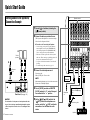 6
6
-
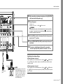 7
7
-
 8
8
-
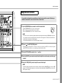 9
9
-
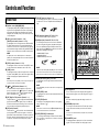 10
10
-
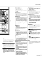 11
11
-
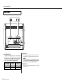 12
12
-
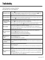 13
13
-
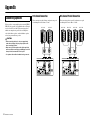 14
14
-
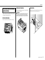 15
15
-
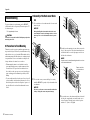 16
16
-
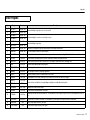 17
17
-
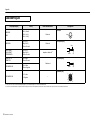 18
18
-
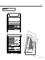 19
19
-
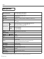 20
20
-
 21
21
-
 22
22
-
 23
23
-
 24
24


Yamaha EMX5 El manual del propietario
- Categoría
- Amplificadores de audio
- Tipo
- El manual del propietario
en otros idiomas
- français: Yamaha EMX5 Le manuel du propriétaire
- italiano: Yamaha EMX5 Manuale del proprietario
- English: Yamaha EMX5 Owner's manual
- Deutsch: Yamaha EMX5 Bedienungsanleitung
- русский: Yamaha EMX5 Инструкция по применению
- Nederlands: Yamaha EMX5 de handleiding
- português: Yamaha EMX5 Manual do proprietário
- dansk: Yamaha EMX5 Brugervejledning
- polski: Yamaha EMX5 Instrukcja obsługi
- čeština: Yamaha EMX5 Návod k obsluze
- svenska: Yamaha EMX5 Bruksanvisning
- Türkçe: Yamaha EMX5 El kitabı
- suomi: Yamaha EMX5 Omistajan opas
- română: Yamaha EMX5 Manualul proprietarului
Artículos relacionados
-
Yamaha VXS3FW Guía de instalación
-
Yamaha EMX7 El manual del propietario
-
Yamaha EMX2 El manual del propietario
-
Yamaha MGP12X Manual de usuario
-
-
-
-
-
-
Yamaha MG12XU El manual del propietario