Cafe CVM9179SLSS Guía de instalación
- Categoría
- Microondas
- Tipo
- Guía de instalación

Questions? Call 800.GE.CARES (800.432.2737) or Visit our Website at: GEAppliances.com
READ CAREFULLY.
KEEP THESE INSTRUCTIONS
.
Installation
Over the Range
Instructions
Microwave Oven
Read these instructions completely and carefully.
•
IMPORTANT – Save these
instructions for local inspector’s use.
•
IMPORTANT – Observe all
governing codes and ordinances.
• Note to Installer – Be sure to leave these
instructions with the Consumer.
BEFORE YOU BEGIN
• Note to Consumer – Keep these
instructions for future reference.
• Skill level – Installation of this appliance requires basic
mechanical and electrical skills.
• Proper installation is the responsibility of the installer.
• Product failure due to improper installation is not
covered under the Warranty.
49-40769 03-16 GE
LA SECCIÛN EN ESPAÒOL EMPIEZA
EN LA P·GINA 25.

2
Outside Back Exhaust ...........................................16-19
Preparing Rear Wall for
Outside Back Exhaust ......................................16
Attach Mounting Plate to Wall ...............16 17
Preparation of Top Cabinet ........................... 17
Adapting Microwave Blower
for Outside Back Exhaust ..........................17, 18
Mount the Microwave Oven ..........................19
Recirculating ............................................................ 20-23
Attach Mounting Plate to Wall .....................20
Preparation of Top Cabinet ...........................20
Check Blower Motor Orientation ................21
Adapting Microwave Blower
for Recirculation .........................................21, 22
Mount the Microwave Oven ..................22, 23
Installing the Charcoal Filter .........................23
Before You Use Your Microwave ........................................ 24
CONTENTS
General information
Important Safety Instructions ................................................ 3
Electrical Requirements ............................................................. 3
Hood Exhaust .............................................................................. 4, 5
Damage – Shipment/Installation .......................................... 6
Parts Included .................................................................................. 6
Tools You Will Need ...................................................................... 7
Mounting Space .............................................................................. 7
Step-by-step installation guide
Placement of Mounting Plate .......................................... 8–10
Removing the Mounting Plate.................................... 8
Finding the Wall Studs ................................................... 8
Determining Wall Plate Location .............................. 9
Aligning the Wall Plate ................................................ 10
Installation Types ................................................................ 11–23
Outside Top Exhaust ............................................ 12–15
Attach Mounting Plate to Wall ..................... 12
Preparation of Top Cabinet ........................... 13
Check Blower Motor Orientation ................ 13
Adapting Blower for Outside
Ventilation .......................................................13, 14
Check for Proper Damper
Operation ............................................................... 14
Mount the Microwave Oven ...................14, 15
Adjust the Exhaust Adaptor ..........................15
Connecting Ductwork ...................................... 15
A
C
Installation Instructions
B

IMPORTANT SAFETY INSTRUCTIONS
3
Installation Instructions
A qualified electrician must perform a ground continuity
check on the wall receptacle before beginning the
installation to ensure that the outlet box is properly
grounded. If not properly grounded, or if the wall
receptacle does not meet electrical requirements noted
(under ELECTRICAL REQUIREMENTS), a qualified electrician
should be employed to correct any deficiencies.
WARNING
Risk of Electric Shock.
Can cause injury or death:
Remove house fuse or
open circuit breaker before
beginning installation to avoid
severe or fatal shock injury.
WARNING
Risk of Electric Shock.
Can cause injury or death: THIS
APPLIANCE MUST BE PROPERLY
GROUNDED to avoid severe or
fatal shock.
The power cord of this
appliance is equipped with
a three-prong (grounding)
plug which mates with
a standard three-prong
(grounding) wall receptacle
to minimize the possibility
of electric shock hazard
from this appliance.
Where a standard two-prong wall receptacle is
encountered, it must be replaced with a properly grounded
three-prong wall receptacle, installed by a qualified
electrician.
WARNING
Risk of Electric Shock.
Can cause injury or death: DO NOT, under any
circumstances, cut, deform or remove any of the prongs
from the power cord. Do not use with an extension cord.
Failure to comply may cause fire.
Ensure proper
ground exists
before use
CAUTION
For personal safety,
the mounting surface must be capable of supporting
the cabinet load, in addition to the added weight of this
63–85 pound product, plus additional oven loads of up
to 50 pounds or a total weight of 113–135 pounds.
CAUTION
For personal safety, this product
cannot be installed in cabinet arrangements such as an
island or a peninsula. It must be mounted to BOTH a top
cabinet AND a wall.
CAUTION
To avoid the risk of personal injury
(back injury or other injuries due to excessive weight of
the microwave oven) or property damage, you will need
two people to install this microwave oven.
ELECTRICAL
REQUIREMENTS
Product rating is 120 volts AC, 60 Hertz, 15 amps and
1.75 kilowatts. This product must be connected to a
supply circuit of the proper voltage and frequency. Wire
size must conform to the requirements of the National
Electrical Code or the prevailing local code for this
kilowatt rating. The power supply cord and plug should
be brought to a separate 15- to 20-ampere branch
circuit single grounded outlet. The outlet box should
be located in the cabinet above the microwave oven.
The outlet box and supply circuit should be installed
by a qualified electrician and conform to the National
Electrical Code or the prevailing local code.
This is the safety alert symbol. This symbol alerts you to potential hazards that can kill or hurt you and others. All safety
messages will follow the safety alert symbol and the word “DANGER”, “WARNING”, or “CAUTION”. These words are defined as:
Indicates a hazardous situation which, if not avoided, will result in death or serious injury.
Indicates a hazardous situation which, if not avoided, could result in death or serious injury.
Indicates a hazardous situation which, if not avoided, could result in minor or moderate injury.
WARNING
DANGER
CAUTION

4
HOOD EXHAUST
The following chart describes an example of one possible
ductwork installation.
NOTE: Read these next two pages only if you plan to vent your exhaust to the
outside. If you plan to recirculate the air back into the room, proceed to page 11.
OUTSIDE TOP EXHAUST (EXAMPLE ONLY)
NOTE: For back exhaust, care should be taken to align exhaust with space between studs, or wall should be prepared at
the time it is constructed by leaving enough space between the wall studs to accommodate exhaust.
* IMPORTANT: If a rectangular-to-round transition adaptor is used, the bottom corners of the damper
will have to be cut to fit, using the tin snips, in order to allow free movement of the damper.
The following chart describes an example of one possible
ductwork installation.
Installation Instructions
OUTSIDE BACK EXHAUST (EXAMPLE ONLY)
EQUIVALENT NUMBER EQUIVALENT
DUCT PIECES LENGTH x USED = LENGTH
Roof Cap 24 Ft. x (1) = 24 Ft.
12 Ft. Straight Duct 12 Ft. x (1) = 12 Ft.
(6s Round)
Rectangular-to-Round 5 Ft. x (1) = 5 Ft.
Transition Adaptor*
Equivalent lengths of duct pieces are based on actual tests and
reflect requirements for good venting performance with any vent hood.
Total Length = 41 Ft.
EQUIVALENT NUMBER EQUIVALENT
DUCT PIECES LENGTH* x USED = LENGTH
Wall Cap 40 Ft. x (1) = 40 Ft.
3 Ft. Straight Duct 3 Ft. x (1) = 3 Ft.
(3
1
ø4s x 10s Rectangular)
90° Elbow 10 Ft. x (2) = 20 Ft.
Equivalent lengths of duct pieces are based on actual tests and
reflect requirements for good venting performance with any vent hood.
Total Length = 63 Ft.

EQUIVALENT NUMBER EQUIVALENT
DUCT PIECES LENGTH x USED = LENGTH
Rectangular-to-Round 5 Ft. x ( ) = Ft.
Transition Adaptor*
Wall Cap 40 Ft. x ( ) = Ft.
90° Elbow 10 Ft. x ( ) = Ft.
45° Elbow 5 Ft. x ( ) = Ft.
90° Elbow 25 Ft. x ( ) = Ft.
45° Elbow 5 Ft. x ( ) = Ft.
Roof Cap 24 Ft. x ( ) = Ft.
Straight Duct 6s Round or 1 Ft. x ( ) = Ft.
3
1
ø4s x 10s Rectangular
Total Ductwork = Ft.
Equivalent lengths of duct pieces are based on actual tests
and reflect requirements for good venting performance with
any vent hood.
* IMPORTANT: If a rectangular-to-round transition
adaptor is used, the bottom corners of the damper
will have to be cut to fit, using the tin snips, in order to
allow free movement of the damper
.
NOTE: If you need to install ducts, note that the total duct
length of 3
1
ø4s x 10s rectangular or 6s diameter round duct
should not exceed 140 equivalent feet.
Outside ventilation requires a HOOD EXHAUST DUCT. Read
the following carefully.
NOTE: It is important that venting be installed using
the most direct route and with as few elbows as possible.
This ensures clear venting of exhaust and helps prevent
blockages. Also, make sure dampers swing freely and
nothing is blocking the ducts.
Exhaust connection:
The hood exhaust has been designed to mate with
a standard 3
1
ø4s x 10s rectangular duct.
If a round duct is required, a rectangular-to-round
transition adaptor must be used. Do not use less than
a 6s diameter duct.
Maximum duct length:
For satisfactory air movement, the total duct length of
3
1
ø4s x 10s rectangular or 6s diameter round duct should
not exceed 140 equivalent feet.
Elbows, transitions, wall and roof caps, etc.,
present additional resistance to airflow and are equivalent
to a section of straight duct which is longer than their
actual physical size. When calculating the total duct
length, add the equivalent lengths of all transitions and
adaptors plus the length of all straight duct sections. The
chart below shows you how to calculate total equivalent
ductwork length using the approximate feet of equivalent
length of some typical ducts.
5
Installation Instructions

PART QUANTITY
Top Cabinet 1
Template
Rear Wall 1
Template
Installation 1
Instructions
Separately 2
Packed
Grease
Filter
6
PART QUANTITY
Wood Screws 2
(
1
ø4s x 2s)
Toggle Bolts (and 2
wing nuts) (
3
ø16s x 3s)
Self-Aligning Machine
3
Screws (
1
ø4s-28 x 3
1
ø4s)
Nylon Grommet 1
(for metal cabinets)
• If the unit is damaged in shipment, return the unit
to the store in which it was bought for repair or
replacement.
• If the unit is damaged by the customer, repair or
replacement is the responsibility of the customer.
• If the unit is damaged by the installer (if other than
the customer), repair or replacement must be made
by arrangement between customer
and installer.
DAMAGE – SHIPMENT/
INSTALLATION
PARTS INCLUDED
You will find the installation hardware contained in a
packet with the unit. Check to make sure you have all
these parts.
NOTE: Some extra parts are included.
HARDWARE PACKET
ADDITIONAL PARTS
Installation Instructions

7
TOOLS YOU WILL NEED
# 1 and #2 Phillips screwdriver
Pencil
Ruler or tape measure
and straight edge
Carpenter square
(optional)
Tin snips (for cutting
damper, if required)
Electric drill with
3
ø16s,
1
ø2s and
5
ø8s drill bits
Hammer (optional)
Stud finder or
Filler blocks or scrap
wood pieces, if needed
for top cabinet spacing
(used on recessed
bottom cabinet
installations only)
Gloves
Saw (saber, hole or keyhole)
Level
Duct and masking tape
MOUNTING SPACE
NOTES:
• The space between the cabinets must be
30s wide and free of obstructions.
• If the space between the cabinets is greater
than 30s, a Filler Panel Kit may be used to fill
in the gap between the microwave oven and
the cabinets. Your Owner’s Manual contains
the kit number for your model.
• This microwave oven is for installation over ranges
up to 36s wide.
• If you are going to vent your microwave oven
to the outside, see Hood Exhaust Section for
exhaust duct preparation.
• When installing the microwave oven beneath
smooth, flat cabinets, be careful to follow the
instructions on the top cabinet template for
power cord clearance.
• Models with top venting grilles: Do not allow
cabinetry or other objects to block the airflow
of the vent.
* 13” max: for standard installation, 15” cabinet
depth requires additional steps using an
additional installation kit JX15BUMPWW/BB.
Backsplash
66s or More
from the
Floor to the
Top of the
Microwave
30s
2s
30s
min.
16
1
ø2s
Bottom Edge of
Cabinet Needs
to be 30s or
More from the
Cooking Surface
Installation Instructions
Scissors
(to cut template, if
necessary)
Safety goggles
13s
max.*
Minimum distance
from door hinge
side to adjacent
wall should
equal 3/4”

8
Find the studs, using one of the following
methods:
A. Stud finder – a magnetic device which
locates nails.
OR
B. Use a hammer to tap lightly across the
mounting surface to find a solid sound.
This will indicate a stud location.
After locating the stud(s), find the center by
probing the wall with a small nail to find the edges
of the stud. Then place a mark halfway between the
edges. The center of any adjacent studs should be
16s or 24s from this mark.
Draw a line down the center of the studs.
THE MICROWAVE MUST BE CONNECTED TO
AT LEAST ONE WALL STUD.
1
Remove the installation instructions, filters, glass
tray and the small hardware bag. Do not remove the
foam protecting the front of the oven.
Fold back all 4 carton flaps fully against carton sides.
Then carefully roll the oven and carton over onto the
top side. The oven should be resting in the foam.
REMOVING THE MICROWAVE
OVEN FROM THE CARTON/
REMOVING THE MOUNTING PLATE
FINDING THE WALL STUDS
B
.
A
.
2
PLACEMENT OF THE MOUNTING PLATE
1
Wall
Studs
Center
3
Carton
Pull the carton up and off the oven.
Remove the 2 screws from the mounting plate. This
plate will be used as the rear wall template and for
mounting. You may discard these screws.
Mounting
Plate
Screws
foam
Installation Instructions
2
3
5
Remove and properly discard plastic bags.
4
1

9
DETERMINING WALL PLATE LOCATION UNDER YOUR CABINET
C.
Your cabinets may have decorative trim that interferes
with the microwave installation. Remove the decorative
trim to install the microwave properly and to make it
level.
THE MICROWAVE MUST BE LEVEL.
Use a level to make sure the cabinet bottom is level.
If the cabinets have a front overhang only, with no
back or side frame, install the mounting plate down
the same distance as the front overhang depth. This
will keep the microwave level.
Measure the inside depth of the front overhang.
Draw a horizontal line on the back wall an equal
distance below the cabinet bottom as the inside depth
of the front overhang.
For this type of installation with front overhang only,
align the mounting tabs with this horizontal line, not
touching the cabinet bottom as described in Step D.
Plate position – beneath flat bottom
cabinet
Plate position – beneath recessed bottom
cabinet with front overhang
Mounting Plate Tabs
Touching the Cabinet
Bottom
Mounting Plate with
Tabs Below Cabinet
Bottom the Same
Distance as the Front
Overhang Depth
At least 30s, up to 36s
Plate position – beneath framed recessed
cabinet bottom
Mounting Plate Tabs
Touching the Back
Frame
Installation Instructions
30s to Cooktop
30s to Cooktop
1
2
3

10
ALIGNING THE WALL PLATE
Draw a vertical line on the wall at the center of the
30s wide space.
Use the mounting plate as the template for the rear
wall. Place the mounting plate on the wall, making
sure that the tabs are touching the bottom of the
cabinet or the level line drawn in Step C for cabinets
with front overhang. Line up the notch and centerline
on the bottom of the mounting plate to the centerline
on the wall.
While holding the mounting plate with one hand,
draw circles on the wall at holes A, B, C and D
(see illustration above/actual plate marked with arrows) .
Four holes must be used for mounting.
NOTE: Holes C and D are inside area E. If neither
C nor D is in a stud, find a stud somewhere in area E and
draw a fifth circle to line up with the stud. It is important
to use at least one wood screw mounted
firmly in a stud to support the weight of the microwave.
Set the mounting plate aside.
WARNING
Risk of electric shock. Can cause injury
or death. Take care to not drill into electrical wiring inside
walls or cabinets.
Drill holes on the circles. If there is a stud, drill a
3
ø16s
hole for wood screws. For holes that don’t line up with
a stud, drill a
5
ø8s hole for toggle bolts. Drill two 5/8”
holes for toggle screws.
NOTE: DO NOT MOUNT THE PLATE AT THIS TIME.
1
2
3
4
Draw a Vertical
Line on Wall
from Center of
Top Cabinet
Area E
Hole A
Hole B
Hole D
Hole C
D.
Installation Instructions
CAUTION
Wear gloves to avoid cutting
fingers on sharp edges.
Centerline
Notches

A
INSTALLATION TYPES
(Choose A, B or C)
This microwave oven is designed for adaptation to
the following three types of ventilation:
A. Outside Top Exhaust (Vertical Duct)
B. Outside Back Exhaust (Horizontal Duct)
C. Recirculating (Non-Vented Ductless)
NOTE: This microwave is shipped assembled for Outside Top
Exhaust (except for non-vented models). Select the type of
ventilation required for your installation and
proceed to that section.
OUTSIDE TOP EXHAUST
(VERTICAL DUCT)
OUTSIDE BACK EXHAUST
(HORIZONTAL DUCT)
RECIRCULATING
(NON-VENTED DUCTLESS)
See page 12
See page 16
See page 20
A Charcoal Filter Accessory Kit
is required for the non-vented
exhaust. (See your
Owner’s Manual for the kit
number.)
Adaptor in Place for
Outside Top Exhaust
Installation Instructions
2
B
C
11

Place the mounting plate against the wall and insert
the toggle wings into the holes in the wall
to mount the plate.
NOTE: Before tightening toggle bolts and wood screw,
make sure the tabs on the mounting plate touch the
bottom of the cabinet when pushed
flush against the wall and that the plate is properly
centered under the cabinet.
CAUTION
Be careful to avoid pinching
fingers between the back of the mounting plate
and the wall.
Tighten all bolts. Pull the plate away from the wall to
help tighten the bolts.
3
A
4
12
OUTSIDE TOP EXHAUST
(Vertical Duct)
INSTALLATION OVERVIEW
A1. Attach Mounting Plate to Wall
A2. Prepare Top Cabinet
A3. Check Blower Motor Oientation
A4. Adapt Blower for Outside Ventilation
A5. Check Damper Operation
A6. Mount Microwave Oven
A7. Adjust Exhaust Adaptor
A8. Connect Ductwork
Wall
Mounting
Plate
Spacing for
Toggles More Than
Wall Thickness
Bolt End
Toggle
Bolt
Toggle Wings
To use toggle bolts:
Installation Instructions
ATTACH THE MOUNTING PLATE
TO THE WALL
A1
Attach the plate to the wall using toggle bolts. At least
one wood screw must be used to attach the plate to
a wall stud. Recommended locations on the mounting
plate are indicated by A, B, C and D.
Remove the toggle wings from the bolts.
Insert the bolts into the mounting plate through
the holes designated to go into drywall and reattach
the toggle wings to
3
ø4s onto each bolt.
1
2
A
B
C
D

13
USE TOP CABINET TEMPLATE FOR
PREPARATION OF TOP CABINET
You need to drill holes for the top support screws, a hole
large enough for the power cord to fit through, and a
cutout large enough for the exhaust adaptor.
CHECK BLOWER MOTOR
ORIENTATION
The blower fan blade opening should be facing the top
of the microwave. If the fan opening is already facing
the top of the microwave, skip to Step A5. Otherwise,
continue to Step A4 to adjust the motor orientation.
ADAPTING BLOWER FOR
OUTSIDE VENTILATION
Remove and save the screws that hold the blower
motor to the microwave oven.
Remove and save the metal blower shield on the top
of the microwave by sliding it right.
ADAPTING BLOWER FOR
OUTSIDE VENTILATION (Cont.)
Attached the metal blower shield to the backside of
the microwave oven by sliding it down.
Open the blower door by lifting it up at the back of
the microwave oven.
Carefully pull out the blower unit. The wires will
extend far enough to allow you to adjust the blower
unit.
5ROOWKHEORZHUXQLWÛVRWKDWWKHIDQEODGH
openings are facing the top.
A2.
A3.
A4.
A4.
• Read the instructions on the TOP CABINET
TEMPLATE.
• Tape it underneath the top cabinet.
• Drill the holes, following the instructions on the TOP
CABINET TEMPLATE.
CAUTION
Wear safety goggles when drilling
holes in the cabinet bottom.
Installation Instructions
1
3
4
5
6
2
Back of Oven
Blower Motor
Screws
Blower Plate
BEFORE: Fan Blade
Openings Facing
Forward
AFTER: Fan Blade
Openings Facing
Up
Blower
Shield
Roll
NOTE: Make
sure wires
remain routed
in the grooves
of the motor
frame.
Blower Motor
Screw

14
Installation Instructions
ADAPTING BLOWER FOR
OUTSIDE VENTILATION (Cont.)
Place the blower unit back into the opening.
CAUTION
Do not pull or stretch the blower
unit wiring. Make sure the wires are not pinched.
Close the blower door. Secure the blower to the
microwave using the screws from Step 1.
A4.
7
8
CHECK FOR PROPER
DAMPER OPERATION
A5.
Exhaust Adaptor
Blower Plate
Damper
Back of
Microwave
Oven
• Place the microwave in its upright position, with the
top of the unit facing up.
• Make sure tape securing damper is removed and
damper pivots easily before mounting microwave.
• Slide the damper into place. Make sure it catches
in the retaining hooks to secure.
• You will need to make adjustments to assure proper
alignment with your house exhaust duct after the
microwave is installed.
Retaining Hooks
3
MOUNT THE MICROWAVE OVEN
A6.
CAUTION
FOR EASIER INSTALLATION AND
PERSONAL SAFETY, WE RECOMMEND THAT TWO
PEOPLE INSTALL THIS MICROWAVE OVEN.
IMPORTANT: Do not grip or use handle
during installation.
NOTE: If your cabinet is metal, use the nylon
grommet around the power cord hole to prevent
cutting of the cord.
NOTE: We recommend using filler blocks if the
cabinet front hangs below the cabinet bottom shelf.
IMPORTANT: If filler blocks are not
used, case damage may occur from
overtightening screws.
Insert a self-aligning screw through top center
cabinet hole. Temporarily secure the oven by
turning the screw at least two full turns after
the threads have engaged. (It will be completely
tightened later.) Be sure to keep power cord tight.
Be careful not to pinch the cord, especially when
mounting flush to bottom of cabinet.
NOTE: When mounting the
microwave oven, thread
power cord through hole
in bottom of top cabinet.
Keep it tight throughout
Steps 1–3. Do not pinch
cord or lift oven by pulling
cord.
Lift microwave, tilt it
forward, and hook slots
at back bottom edge
onto four lower tabs of
mounting plate.
1
2
Rotate front of oven up
against cabinet
bottom.

15
4
Attach the microwave oven to the top cabinet.
7
6
Cabinet Front
Cabinet Bottom Shelf
Tighten the outer three screws to the top of the
microwave oven. (While tightening screws, hold
the microwave oven in place against the wall and
the top cabinet.)
Install grease filter. See the Owner’s Manual on
the website (GEAppliances.com).
Filler Block
Microwave Oven Top
Equivalent
to Depth
of Cabinet
Recess
Insert 3 self-aligning screws
through outer top cabinet
holes. Turn two full turns on
each screw.
Installation Instructions
ADJUST THE EXHAUST ADAPTOR
A7.
Open the top cabinet and adjust the exhaust adaptor to
connect to the house duct.
Back of
Microwave
Oven
For Side-to-Side Adjustment,
Slide the Exhaust Adaptor
as Needed
Damper
CONNECTING DUCTWORK
1
2
Extend the house duct down to connect to
the exhaust adaptor.
Seal exhaust duct joints using duct tape.
A8.
House Duct
Self-Aligning Screw
5
MOUNT THE MICROWAVE OVEN
(cont.)
A6.
T
u
r
n
t
o
S
e
l
e
c
t
P
r
e
s
s
t
o
E
n
t
e
r
Reheat
Timer
On/Off
Defrost
Weight/Time
Start
Pause
Cancel
Off
Lock Controls
Hold 3 Sec
Cook
Time
Set
Clock
Options Help
Surface
Light
Vent Fan
Popcorn
B
everage
Microwave
Express
Warm
Power
Level
Auto
Cook
Combination
Fast Bake
Convection
Roast
Turntable
Convection
Bake

OUTSIDE BACK EXHAUST
(Horizontal Duct)
INSTALLATION OVERVIEW
B1. Prepare Rear Wall
B2. Attach Mounting Plate to Wall
B3. Prepare Top Cabinet
B4. Adjust Blower
B5. Mount the Microwave Oven
Installation Instructions
B
PREPARING THE REAR WALL FOR
OUTSIDE BACK EXHAUST
B1.
You need to cut an opening in the rear wall for outside
exhaust.
• Read the instructions on the REAR WALL TEMPLATE.
• Tape it to the rear wall, lining up with the holes
previously drilled for holes A and B in the wall plate.
• Cut the opening, following the instructions of the
REAR WALL TEMPLATE.
16
ATTACH THE MOUNTING PLATE
TO THE WALL
B2
Attach the plate to the wall using toggle bolts. At least
one wood screw must be used to attach the plate to
a wall stud. Recommended locations on the mounting
plate are indicated by A, B, C and D.
Remove the toggle wings from the bolts.
Insert the bolts into the mounting plate through
the holes designated to go into drywall and reattach
the toggle wings to
3
ø4s onto each bolt.
1
2
A
B
C
D

17
USE TOP CABINET TEMPLATE FOR
PREPARATION OF TOP CABINET
B3.
• Read the instructions on the TOP CABINET TEMPLATE.
• Tape it underneath the top cabinet.
• Drill the holes, following the instructions on the
TOP CABINET TEMPLATE.
CAUTION
: Wear safety goggles when drilling
holes in the cabinet bottom.
Wall
Mounting
Plate
Spacing for Toggles More
Than Wall Thickness
Toggle
Bolt
Toggle Wings
To use toggle bolts:
Bolt End
Installation Instructions
You need to drill holes for the top support screws and a
hole large enough for the power cord to fit through.
Place the mounting plate against the wall and insert
the toggle wings into the holes in the wall
to mount the plate.
NOTE: Before tightening toggle bolts and wood screw,
make sure the tabs on the mounting plate touch the
bottom of the cabinet when pushed flush against the
wall and that the plate is properly centered under the
cabinet.
CAUTION
Be careful to avoid pinching
fingers between the back of the mounting plate and
the wall.
Tighten all bolts. Pull the plate away from the wall to
help tighten the bolts.
3
4
1
Remove and save screws that holds blower motor
to microwave oven.
ADAPTING MICROWAVE
BLOWER FOR OUTSIDE BACK
EXHAUST
B4.
Back of Microwave Oven
2
Open the blower door by lifting it up at the back of
the microwave. Remove and save the blower shield
on the back of the microwave by sliding it up.
Remove and save the metal vent fan cover on the
back of the microwave by sliding it up.
4
Rotate blower unit counterclockwise 180°.
Before Rotation After Rotation
Back of
Microwave Oven
Back of
Microwave Oven
3
BEFORE: Fan Blade
Openings Facing Up
End B
End A
Carefully pull out the blower unit. The wires
will extend far enough to allow you to adjust the
blower unit.
Blower Retaining
Screws

Installation Instructions
18
ADAPTING MICROWAVE
BLOWER FOR OUTSIDE BACK
EXHAUST (cont.)
B4.
Roll the blower unit 90° so that fan blade
openings are facing out the back of the
microwave.
5
Gently remove the wires from the grooves. Reroute
the wires through grooves on other side of the
blower unit.
Before Rerouting After Rerouting
Wires Routed Through Right
Side
Wires Routed Through Left
Side
Before Rolling After Rolling
Back of
Microwave
Oven
Back of
Microwave
Oven
6
Locate the two “knockout” plates, on the rear
oven panel, near the top of the oven. Using tin
snips, carefully cut the web area from the two
holes side-by-side (that secure the knockouts
to the oven). Cut all four webs on both rear
knockouts; this will allow the ventilation fan
airflow to exhaust out the rear of the oven.
CAUTION
Be sure to trim the sharp edges
from the openings after removing the knockout
plates.
7
9
Close the blower door. Slide blower shield onto the
top of the blower door opening. Secure the blower
to the microwave oven using the blower retaining
screws from Step 1 except the upper blower motor
retaining screw
Back of
Microwave
Oven
Blower Retaining
Screw
Blower Retaining
Screw
Blower Shield
AFTER: Fan Blade
Openings Facing Back
8
Place the blower unit back into the opening.
The blower unit exhaust openings should match
exhaust openings on rear of microwave.
CAUTION
Do not pull or stretch the
blower unit wiring. Make sure the wires are not
pinched.
End A
End B
Slide the exhaust adaptor onto the back
of the microwave oven, securing it into the
lower locking tabs. Take care to ensure that the
damper hinge is installed so that it is at the top
and that the damper swings freely. Reinstall the
upper blower motor screw through the adaptor
and the blower door and into the back of the
microwave oven.
10
Guide
Guide
Adaptor
Locking Tabs
(not shown)
Back of
Microwave Oven
Blower Motor
Door Retaining
Screw

19
Installation Instructions
Attach the microwave oven to the top cabinet.
Insert 3 self-aligning screws through outer top
cabinet holes. Turn two full turns on each screw.
3
MOUNT THE MICROWAVE OVEN
B5.
CAUTION
FOR EASIER INSTALLATION AND
PERSONAL SAFETY, WE RECOMMEND THAT TWO
PEOPLE INSTALL THIS MICROWAVE OVEN.
IMPORTANT: Do not grip or use handle
during installation.
NOTE: If your cabinet is metal, use the nylon grommet
around the power cord hole to prevent cutting of the
cord.
NOTE: We recommend using filler blocks if the cabinet
front hangs below the cabinet bottom shelf.
IMPORTANT: If filler blocks are not
used, case damage may occur from
overtightening screws.
Insert a self-aligning screw through top center cabinet
hole. Temporarily secure the oven by turning the
screw at least two full turns after the threads have
engaged. (It will be completely tightened later.) Be
sure to keep power cord tight. Be careful not to pinch
the cord, especially when mounting flush to bottom of
cabinet.
Lift microwave, tilt it forward, and hook slots at back
bottom edge onto four lower tabs of mounting plate.
NOTE: When mounting the microwave oven, thread
power cord through hole in bottom of top cabinet.
Keep it tight throughout Steps 1–3. Do not pinch cord
or lift oven by pulling cord.
5
Cabinet Front
Cabinet Bottom Shelf
7
Tighten the outer three screws to the top of the
microwave oven. (While tightening screws, hold
the microwave oven in place against the wall and
the top cabinet.)
Install grease filter. See the Owner’s Manual
packed with the microwave.
Filler Block
Microwave Oven Top
Equivalent
to Depth
of Cabinet
Recess
Self-Aligning Screws
Self-Aligning Screw
6
4
1
2
Rotate front of oven up against cabinet bottom.
Power Cord
T
u
r
n
t
o
S
e
l
e
c
t
P
r
e
s
s
t
o
E
n
t
e
r
Reheat
Timer
On/Off
Defrost
Weight/Time
Start
Pause
Cancel
Off
Lock Controls
Hold 3 Sec
Cook
Time
Set
Clock
Options Help
Surface
Light
Vent Fan
Popcorn
B
everage
Microwave
Express
Warm
Power
Level
Auto
Cook
Combination
Fast Bake
Convection
Roast
Turntable
Convection
Bake

USE TOP CABINET TEMPLATE FOR
PREPARATION OF TOP CABINET
C2.
20
RECIRCULATING
(Non-Vented Ductless)
INSTALLATION OVERVIEW
C1. Attach Mounting Plate to Wall
C2. Prepare Top Cabinet
C3. Check Blower Motor Orientation
C4. Adapt Blower for Recirculation
C5. Mount the Microwave Oven
C6. Install Charcoal Filter
• Read the instructions on the TOP CABINET
TEMPLATE.
• Tape it underneath the top cabinet.
• Drill the holes, following the instructions on the TOP
CABINET TEMPLATE.
CAUTION
Wear safety goggles when drilling
holes in the cabinet bottom.
Installation Instructions
You need to drill holes for the top support screws and a
hole large enough for the power cord to fit through.
C
Place the mounting plate against the wall and insert
the toggle wings into the holes in the wall
to mount the plate.
NOTE: Before tightening toggle bolts and wood screw,
make sure the tabs on the mounting plate touch the
bottom of the cabinet when pushed flush against the
wall and that the plate is properly centered under the
cabinet.
CAUTION
Be careful to avoid pinching fingers
between the back of the mounting plate and the
wall.
Tighten all bolts. Pull the plate away from the wall to
help tighten the bolts.
3
4
Wall
Mounting
Plate
Spacing for
Toggles More Than
Wall Thickness
Bolt End
Toggle
Bolt
Toggle Wings
To use toggle bolts:
ATTACH THE MOUNTING PLATE
TO THE WALL
C1
Attach the plate to the wall using toggle bolts. At least
one wood screw must be used to attach the plate to
a wall stud. Recommended locations on the mounting
plate are indicated by A, B, C and D.
Remove the toggle wings from the bolts.
Insert the bolts into the mounting plate through
the holes designated to go into drywall and reattach
the toggle wings to
3
ø4s onto each bolt.
1
2
A
B
C
D

AFTER: Fan Blade
Openings Facing
Forward
4
21
Roll the blower unit 90° so that fan blade openings
are facing toward the front of the microwave.
Roll
NOTE: Make sure wires remain routed in the grooves of
the motor frame.
Installation Instructions
BEFORE: Fan Blade
Openings Facing Up
CHECK BLOWER MOTOR
ORIENTATION
ADAPTING MICROWAVE BLOWER
FOR RECIRCULATION
C3.
C4.
1
1
The blower fan blade opening should be facing
the front of the microwave. If the fan opening is
already facing the front of the microwave, skip to
Step C5. Otherwise, continue to Step C4 to adjust
the blower orientation.
Remove and save screws that holds blower motor
to microwave oven.
2
Open the blower door by lifting it up at the back of
the microwave oven.
3
Carefully pull out the blower unit. The wires
will extend far enough to allow you to adjust the
blower unit.
Back of
Microwave
Oven
Blower Motor
Retaining
Screws
5
Place the blower unit back into the opening.
CAUTION
Do not pull or stretch the blower
unit wiring. Make sure the wires are not pinched.

ADAPTING MICROWAVE BLOWER
FOR RECIRCULATION (cont.)
C4.
22
Installation Instructions
NOTE: When mounting the
microwave oven, thread
power cord through hole
in bottom of top cabinet.
Keep it tight throughout
Steps 1–3. Do not pinch
cord or lift oven by pulling
cord.
Lift microwave, tilt it
forward, and hook slots
at back bottom edge
onto four lower tabs of
mounting plate.
2
Rotate front of oven up
against cabinet
bottom.
1
Close the blower door. Slide blower shield onto the
top of the blower door opening.
Remove the metal vent fan cover on the back of the
microwave by sliding it up.
7
6
MOUNT THE MICROWAVE OVEN
C5.
CAUTION
FOR EASIER INSTALLATION AND
PERSONAL SAFETY, WE RECOMMEND THAT TWO
PEOPLE INSTALL THIS MICROWAVE OVEN.
IMPORTANT: Do not grip or use handle during
installation.
NOTE: If your cabinet is metal, use the nylon grommet
around the power cord hole to prevent cutting of the
cord.
NOTE: We recommend using filler blocks if the
cabinet front hangs below the cabinet bottom shelf.
IMPORTANT: If filler blocks are not used,
case damage may occur from overtightening
screws.
Back of
Microwave
Oven
Blower
Retaining
Screws
Blower Retaining
Screw
Secure the blower to the microwave using the blower
retaining screws from Step 1.
8

5
MOUNT THE MICROWAVE OVEN
(cont.)
C5.
23
Installation Instructions
6
7
Tighten the outer three screws to the top of the
microwave oven. (While tightening screws, hold
the microwave oven in place against the wall and
the top cabinet.)
Install grease filter. See the Owner’s Manual
packed with the microwave.
Insert 3 self-aligning screws through outer top
cabinet holes. Turn two full turns on each screw.
Attach the microwave oven to the top cabinet.
Cabinet Front
Cabinet Bottom Shelf
Filler Block
Microwave Oven Top
Equivalent to Depth
of Cabinet Recess
3
Insert a self-aligning screw through top center
cabinet hole. Temporarily secure the oven by
turning the screw at least two full turns after
the threads have engaged. (It will be completely
tightened later.) Be sure to keep power cord tight.
Be careful not to pinch the cord, especially when
mounting flush to bottom of cabinet.
Self-Aligning Screw
4
3
2
1
CHARCOAL FILTER
C6.
Install the charcoal filter. When properly installed,
the wire mesh of the filter should be visible from the
front.
Close the door.
Charcoal
Filter
Insert mesh-side up
Open the filter door by pushing down 2 buttons on
the top of the microwave just above the filter door.
Push the filter at the bottom until it comes free
of the locking tabs. Slide the filter down and out.
4
A charcoal filter is installed in all units. Follow the
steps below to check the filter.
T
u
r
n
t
o
S
e
l
e
c
t
P
r
e
s
s
t
o
E
n
t
e
r
Reheat
Timer
On/Off
Defrost
Weight/Time
Start
Pause
Cancel
Off
Lock Controls
Hold 3 Sec
Cook
Time
Set
Clock
Options Help
Surface
Light
Vent Fan
Popcorn
B
everage
Microwave
Express
Warm
Power
Level
Auto
Cook
Combination
Fast Bake
Convection
Roast
Turntable
Convection
Bake

KEEP INSTALLATION INSTRUCTIONS FOR THE
LOCAL INSPECTOR’S USE.
Plug power cord into a dedicated 15- to 20-amp
electrical outlet.
7.
Read the Owner’s Manual.
6.
Replace house fuse or turn breaker back on.
4.
Remove all packing material from the
microwave oven.
2.
Make sure the microwave oven has been
installed according to instructions.
1.
24
BEFORE YOU USE YOUR MICROWAVE
Ensure proper
ground exists
before use
Installation Instructions
Install turntable and ring in cavity.
3.
5.
Printed in Malaysia

LEA CUIDADOSAMENTE.
GUARDE ESTAS INSTRUCCIONES.
Instrucciones
de instalación
Lea estas instrucciones completa y cuidadosamente.
•
IMPORTANTE – Guarde estas
instrucciones para el uso del inspector local.
•
IMPORTANTE – Cumpla con todos los
códigos y ordenanzas gubernamentales.
• Nota para el instalador – Asegúrese de dejar
estas instrucciones con el consumidor.
ANTES DE EMPEZAR
• Nota para el consumidor – Guarde estas
instrucciones para futura referencia.
• Nivel de destrezas – La instalación de este aparato
requiere de destrezas básicas de mecánica y electricidad.
• La instalación apropiada es responsabilidad
del instalador.
• La falla del producto debido a una instalación
inapropiada no está cubierta por la garantía.
Horno microondas para
colocar encima de la estufa
¿Preguntas? Llame 800.GE.CARES (800.432.2737) o visite nuestra página en la red en: GEAppliances.com
1

2
Escape posterior externo ................................... 16-19
Cómo preparar la pared posterior
para el escape posterior exterior ............... 16
Cómo adherir el plato de montaje
a la pared ........................................................16, 17
Cómo preparar el gabinete superior ........ 17
Cómo adaptar el calefactor
del microondas para el escape
posterior exterior ............................................17, 18
Cómo montar el horno microondas ......... 19
Recirculación ............................................................ 20-23
Cómo adherir el plato de montaje
a la pared ...............................................................20
Cómo preparar el gabinete superior ..........20
Controle la Orientación del Motor del
Calentador .............................................................21
Cómo adaptar el calefactor del
microondas para la recirculación ........21, 22
Cómo montar el horno
microondas ...................................................22, 23
Cómo instalar el filtro de carbonilla ..........23
Antes de comenzar a usar su horno microondas .... 24
CONTENIDO
Información general
Instrucciones de seguridad importantes ......................... 3
Requisitos eléctricos .................................................................... 3
Campana de escape ................................................................ 4, 5
Daños – Envío / Instalación ...................................................... 6
Partes incluidas ............................................................................... 6
Herramientas que necesitará ................................................. 7
Espacio de montaje ....................................................................... 7
Guía de instalación paso por paso
Cómo colocar el plato de montaje ................................ 8–10
Cómo remover el plato de montaje .........................8
Cómo encontrar los postes
de viga en la pared ......................................................... 8
Cómo determinar la localización de las
placas de la pared ........................................................... 9
Cómo alinear la placa de la pared ....................... 10
Tipos de instalación ........................................................... 11–23
Escape superior exterior .................................... 12–15
Cómo adherir la placa de montaje
a la pared ............................................................... 12
Preparación del gabinete superior ............ 13
Controle la Orientación del Motor del
Calefactor .............................................................. 13
Adaptación del Calefactor para la
Ventilación Exterior ...................................13, 14
Cómo inspeccionar si la operación
del regulador de tiro es apropiada ............ 14
Cómo montar el horno
microondas ....................................................14, 15
Cómo ajustar el adaptador de escape .... 15
Cómo conectar la red de conductos ........ 15
A
B
C
Instrucciones de instalación

Instrucciones de instalación
3
INSTRUCCIONES DE SEGURIDAD IMPORTANTES
Un electricista calificado debe realizar una verificación de
continuidad de conexión a tierra en el tomacorriente de
pared antes de comenzar la instalación para garantizar
que la caja de distribución tenga una adecuada conexión
a tierra. Si no cuenta con una adecuada conexión a
tierra, o si el tomacorriente de pared no cumple con
los requisitos eléctricos indicados (bajo REQUISITOS
ELÉCTRICOS), debe contratarse un electricista calificado
para corregir las deficiencias.
ADVERTENCIA
Riesgo
de descarga eléctrica. Puede
provocar una lesión o la muerte:
Quite el fusible o el interruptor
de circuitos de la vivienda antes
de comenzar la instalación para
evitar una lesión por descarga
grave o fatal.
ADVERTENCIA
Riesgo
de descarga eléctrica. Puede
provocar una lesión o la muerte:
ESTE APARATO DEBE CONTAR
CON UNA ADECUADA CONEXIÓN
A TIERRA para evitar una
descarga grave o fatal.
El cable eléctrico de este aparato
está equipado con un enchufe de
tres patas (con conexión a tierra),
lo cual requiere que el mismo
encaje con un tomacorriente para
tres patas (con conexión a tierra)
de pared para minimizar la posibilidad de descargas
eléctricas.
Donde haya un tomacorriente de pared estándar de
dos espigas, resulta indispensable cambiarlo por un
tomacorriente de pared de tres espigas con adecuada
conexión a tierra, instalado por un electricista calificado.
ADVERTENCIA
Riesgo de descarga eléctrica.
Puede provocar una lesión o la muerte: Bajo NINGUNA
circunstancia corte, deforme o quite las clavijas del cable
de energía. No utilice un cable de extensión.
No cumplir con esta indicación puede provocar un
incendio.
Asegúrese
de que existe
una conexión
a tierra
apropiada
antes del uso
PRECAUCIÓN
En pos de la seguridad
personal, la superficie de montaje debe ser capaz de
soportar la carga del gabinete, además del
peso adicional (de 63 a 85 libras) de este producto,
más las cargas adicionales del horno de hasta 50 libras
o un peso total entre 113 y 135 libras.
PRECAUCIÓN
En pos de la seguridad
personal, este producto no puede ser
instalado en sistemas de gabinetes tales como los
llamados “islas” o “penínsulas.” Éste debe ser montado
tanto a un gabinete superior como a una pared.
PRECAUCIÓN
Para evitar el riesgo de una
lesión personal (en la espalda u otras lesiones debido
a peso excesivo del horno microondas) o daños a la
propiedad, hacen falta dos personas para instalar este
horno microondas.
REQUISITOS ELÉCTRICOS
La clasificación del producto es de 120 vatios CA (AC), 60
hertz, 15 amperios y 1.75 kilovatios. Este producto debe
estar conectado a un circuito de suministro del voltaje
y frecuencia apropiados. El tamaño del alambre debe
conformarse a los requisitos del National Electric Code o
al código local en efecto para este índice de kilovatios. El
cable eléctrico de alimentación y el interruptor deberán
llevarse a un tomacorriente único conectado a tierra
de 15 a 20 amperios. La caja del tomacorriente deberá
estar localizada en el gabinete encima del horno. La caja
del tomacorriente debe ser instalada por un electricista
calificado y debe conformarse al National Electrical Code
o al código local en efecto.
Éste es el símbolo de alerta de seguridad. El mismo alerta sobre potenciales riesgos que le pueden producir la muerte o
lesiones tanto a usted como a otras personas. Todos los mensajes de seguridad estarán a continuación del símbolo de alerta de
seguridad y con la palabra “PELIGRO”, “ADVERTENCIA” o “PRECAUCIÓN”. Estas palabras se definen como:
PELIGRO
Indica una situación de riesgo que, si no se evita, producirá la muerte o lesiones graves.
ADVERTENCIA
Indica una situación de riesgo que, si no se evita, podría producir la muerte o lesiones graves.
PRECAUCIÓN
Indica una situación de riesgo que, si no se evita, podría resultar en lesiones menores o moderadas.

4
CAMPANA DE ESCAPE
La siguiente tabla describe un ejemplo de una posible
instalación de red de conductos.
NOTA: Lea las siguientes dos páginas solamente si planea ventilar el escape hacia el exterior.
Si por el contrario planea recircular el aire de vuelta hacia el salón, continúe en la página 11.
ESCAPE SUPERIOR EXTERNO (EJEMPLO SOLAMENTE)
NOTA: Para el escape posterior, se debe tener cuidado al alinear el escape entre los espacios de los postes de viga de la pared, o la pared debería ser
preparada en el momento de su construcción dejando suficiente espacio entre los postes de viga de la pared para acomodar el escape.
LONGITUD NÚMERO LONGITUD
PARTES DEL CONDUCTO EQUIVALENTE x USADO = EQUIVALENTE
Tapa del techo 24 pies x (1) = 24 pies
Conducto recto de 12 pies
12 pies x (1) = 12 pies
(redondo de 6s)
Adaptador de transición
5 pies x (1) = 5 pies
de rectángulo a redondo*
La longitud de las partes de los conductos equivalentes está basada en pruebas reales y reflejan los
requisitos para lograr una buena ventilación con cualquier campana de escape.
Longitud total = 41 pies
* IMPORTANTE: Si se usa un adaptador de transición de rectángulo a redondo, las esquinas del fondo
del regulador de tiros deberán cortarse para que encajen, usando las tijeras de corte, para permitir el movimiento
libre del regulador de tiros.
La siguiente tabla describe un ejemplo de una posible
instalación de red de conductos.
Instrucciones de instalación
ESCAPE POSTERIOR EXTERNO (EJEMPLO SOLAMENTE)
LONGITUD NÚMERO LONGITUD
PARTES DEL CONDUCTO EQUIVALENTE x USADO = EQUIVALENTE
Tapa de pared 40 pies x (1) = 40 pies
Conducto recto de 3 pies
3 pies x (1) = 3 pies
(rectangular de 3
1
ø4s x 10s)
Codo de 90° 10 pies x (2) = 20 pies
La longitud de las partes de los conductos equivalentes está basada en pruebas reales y reflejan los
requisitos para lograr una buena ventilación con cualquier campana de escape.
Longitud total = 63 pies

5
La longitud de las partes de conductos equivalentes está basada
en pruebas reales y reflejan los requisitos para lograr una buena
ventilación con cualquier campana de escape.
* IMPORTANTE: Si se usa un adaptador de transición
de rectángulo a redondo, las esquinas del fondo del
regulador de tiros deberán ser cortadas para que
encajen, usando las tijeras de corte, para permitir el
movimiento libre del regulador de tiros.
NOTA: Si usted necesita instalar conductos, tenga pendiente
que la longitud total del conducto rectangular de 3
1
ø4s x 10s o
el conducto redondo de 6s de diámetro no debe sobrepasar
140 pies equivalentes.
La ventilación externa requiere un CONDUCTO DE CAMPANA
DE ESCAPE. Lea lo siguiente cuidadosamente.
NOTA: Es importante que la ventilación sea instalada usando
la ruta más directa y con la menor cantidad de codos posible.
Esto asegura la ventilación del escape y ayuda a prevenir
bloqueos. También, cerciórese de que el regulador de tiro
pende libremente y nada bloquea los conductos.
Conexiones de escape:
La campana de escape ha sido diseñada para encajar
con un conducto rectangular de 3
1
ø4s x 10s estándar.
Si un conducto redondo es necesario, se debe usar un
adaptador de transición de rectangular a redondo.
No use un conducto menor de 6s de diámetro.
Longitud máxima del conducto:
Para lograr un movimiento satisfactorio del aire, la
longitud total del conducto rectangular de 3
1
ø4s x 10s
o el conducto redondo de 6s de diámetro no debe
sobrepasar 140 pies equivalentes.
Los codos, transiciones, paredes y tapas
de techo, etc.,
presentan resistencia adicional al flujo
de aire y son equivalentes a una sección de conducto
recto el cual es más largo que su tamaño físico real.
Cuando calcule la longitud total del conducto, agregue
las longitudes equivalentes de todas las transiciones
y adaptadores, más la longitud de todas las secciones
de conducto rectas. La tabla más adelante muestra
cómo puede calcular la longitud aproximada de la red
de conductos usando pies aproximados de longitudes
equivalentes de algunos conductos típicos.
Instrucciones de instalación
LONGITUD NÚMERO LONGITUD
PARTES DE CONDUCTO EQUIVALENTE x USADO = EQUIVALENTE
Adaptador de transición de 5 pies x ( ) = pies
rectángulo a redondo*
Tapa de pared 40 pies x ( ) = pies
Codo de 90° 10 pies x ( ) = pies
Codo de 45° 5 pies x ( ) = pies
Codo de 90° 25 pies x ( ) = pies
Codo de 45° 5 pies x ( ) = pies
Tapa de techo 24 pies x ( ) = pies
Conducto recto de 6s redondo
1 pies x ( ) = pies
o rectangular de 3
1
ø4s x 10s
Total red de conductos = pies

6
• Si la unidad se daña durante el envío, devuelva
la unidad al almacén donde la adquirió para
su reparación o reemplazo.
• Si el cliente daña la unidad, la reparación o el
reemplazo es responsabilidad del cliente.
• Si el instalador daña la unidad (si no es el cliente), la
reparación o reemplazo se debe hacer por medio de
un arreglo entre el cliente y el instalador.
'$³26²(19Ë2
INSTALACIÓN
Instrucciones de instalación
PARTE CANTIDAD
Tornillos de madera 2
(
1
ø4s x 2s)
Tornillos basculantes 2
(y tuercas de mariposa)
(
1
ø4s x 3s)
Tornillos de máquina 3
autoalineables
(
1
ø4s-28 x 3
1
ø4s)
Arandela aislante de 1
nilón (para gabinetes
metálicos)
PARTES INCLUIDAS
Usted encontrará los elementos de instalación en
un paquete junto con la unidad. Inspeccione para
cerciorarse de que tiene todas las partes.
NOTA: Se incluyen algunas partes adicionales.
PAQUETE DE ELEMENTOS
PARTES ADICIONALES
PARTE
CANTIDAD
Plantilla para
1
el gabinete
superior
Plantilla para
1
la pared
posterior
Instrucciones
1
de instalación
Filtro de
2
grasa
empacados
por separado

7
HERRAMIENTAS QUE NECESITARÁ
Destornilladores de
estrella # 1 y # 2
Lápiz
Regla recta y cinta
métrica
Escuadra de
carpintero
(opcional)
Tijeras para cortar latón
(para cortar el regulador
de tiro, si es necesario)
Taladro eléctrico con brocas
de
3
ø16s,
1
ø2s y
5
ø8s
un martillo (opcional)
Detector de
postes de viga o
Bloques de relleno o
pedazos de madera,
si son necesarios para
rellenar el gabinete
(usados solamente en la
instalación de gabinetes
apoyados)
Guantes
Sierra (de sable, agujero, o de
ojo de cerradura)
Nivel
Cinta de conductos o
cinta adhesiva protectora
ESPACIO DE MONTAJE
NOTAS:
• El espacio entre los gabinetes debe ser de 30s
de ancho y debe estar libre de obstrucciones.
• Si el espacio entre los gabinetes es mayor de
30s, un “Filler Panel Kit” podría ser necesario para
rellenar las brechas entre el horno y los gabinetes.
Su Manual del Propietario contiene
el número de kit para su modelo.
• Este horno microondas es para ser instalado por
encima de estufas hasta 36s de ancho.
• Si usted se dispone a ventilar su horno microondas
hacia el exterior, ver la Sección de Campana
de Escape para la preparación del conducto de
escape.
• Cuando se instale el horno microondas
debajo de gabinetes de fondos lisos y planos,
tenga cuidado de seguir cuidadosamente
las instrucciones en la plantilla del gabinete
superior para el espacio de tolerancia del cable
eléctrico.
• Modelos con ventilación superior: No permite
que los gabinetes u otros objetos obstruyan
el flujo de aire del ventilador.
* Máx. de 13”: para una instalación estándar,
una profundidad del gabinete de 15” requiere
pasos adicionales utilizando el kit de instalación
adicional JX15BUMPWW/BB.
Protector posterior de
salpicaduras
66s o más
desde el
piso hasta
la parte
superior
del horno
30s
2s
30s
mín.
16-
1
ø2s
El extremo del
fondo del gabinete
necesita estar a
30s o más a partir
de la superficie de
la estufa
Instrucciones de instalación
Tijeras (para cortar la
plantilla, si es necesario)
Gafas de seguridad
13s
máx*.
La distancia mínima
desde el costado
de la bisagra de
la puerta hasta la
pared adyacente
debe equivaler a ¾”.

CÓMO REMOVER EL HORNO
MICROONDAS DEL EMBALAJE /
CÓMO REMOVER EL PLATO
DE MONTAJE
8
Remueva las instrucciones de instalación, los filtros,
la bandeja de cristal, y la bolsa pequeña
del equipo. No remueva el protector frontal de
espuma de poliestireno del horno.
Doble totalmente hacia atrás las cuatro tapas de
cartón hacia los lados opuestos de la caja. Entonces
descubra el horno y el cartón en la parte superior. El
horno debería estar descansando sobre la espuma
de poliestireno.
A
.
Caja
Tire del cartón hacia arriba y lejos del horno.
Remueva los tornillos frontales de las placas de
la montura. Estas placas serán utilizadas como la
plantilla trasera en la pared y para montar. Puede
desechar estos tornillos.
Plato de
montaje
Tornillos
Poliestireno
2
3
5
Remueva y deseche debidamente las bolsas de
plástico.
4
1
Encuentre los postes, usando uno de los
métodos siguientes:
A. Use un detector de postes – un dispositivo
magnético que localiza clavos.
O
B. Use un martillo para golpear ligeramente a
través de la superficie de montaje hasta
encontrar un sonido sólido. Esto indicará que
hay un poste de viga en ese lugar.
Después de localizar el poste o los postes de viga,
encuentre el centro mediante el análisis de la
pared usando un clavo pequeño para darse
cuenta de dónde están los bordes del poste. Luego
coloque una marca en el centro de los bordes.
El centro de cualquier poste adyacente deberá ser
entre 16s ó 24s desde esta marca.
Trace una línea hacia abajo indicando el centro
del poste.
EL HORNO MICROONDAS DEBE CONECTARSE POR LO
MENOS A UN POSTE DE LA PARED.
1
CÓMO ENCONTRAR LOS POSTES
DE VIGA EN LA PARED
B
.
2
CÓMO COLOCAR EL PLATO DE MONTAJE
1
Postes de viga
en la pared
Centro
3
Instrucciones de instalación

9
CÓMO DETERMINAR LA LOCALIZACIÓN DEL PLATO DE MONTAJE DEBAJO DE SU
GABINETE
C.
Sus gabinetes podrían tener marcos de decoración
que interfieran con la instalación del horno microondas.
Remueva los marcos decorativos para instalar el horno
apropiadamente y para hacer que quede nivelado.
EL HORNO MICROONDAS DEBE QUEDAR NIVELADO.
Use un nivel para cerciorarse de que el fondo del
gabinete está nivelado.
Si los gabinetes tienen un saliente frontal solamente, sin
marco posterior o lateral, instale el plato de montaje a
la misma distancia de la profundidad del saliente. Este
mantendrá el horno microondas nivelado.
Mida la profundidad interna del frente del saliente.
Trace una línea horizontal en la pared posterior a una
distancia debajo del fondo del gabinete igual
a la profundidad interna del frente saliente.
Para este tipo de instalación con saliente frontal
solamente, alinee las orejillas de montaje con la línea
horizontal, sin tocar el fondo del gabinete como se
describió en el Paso D.
Posición del plato – debajo de gabinetes
de fondo plano
Posición del plato – debajo de gabinetes
de fondo apoyado con frente saliente
Las orejillas del plato de
montaje tocan el fondo
del gabinete
Plato de montaje
con orejillas por
debajo del fondo
del gabinete a la
misma distancia
que la profundidad
del saliente
Por lo menos 30s, hasta 36s
Posición del plato – debajo de gabinetes
de fondo apoyado en un marco
Las orejillas del
plato de montaje
tocan el marco
posterior
Instrucciones de instalación
30s hasta la estufa
30s hasta la estufa
1
2
3

10
CÓMO ALINEAR EL PLATO DE MONTAJE SOBRE LA PARED
Trace una línea vertical en la pared en el centro del
espacio de 30s de ancho.
Use el plato de montaje como la plantilla para la pared
posterior. Coloque el plato de montaje en la pared,
cerciorándose de que las orejillas se encuentran tocando
el fondo del gabinete o la línea horizontal trazada en
el Paso C para gabinetes con saliente frontal. Alinee
la muesca y línea del centro en el fondo del plato de
montaje con la línea de centro en la pared.
Mientras sostiene el plato de montaje con una mano,
trace círculos en la pared en los agujeros A, B, C y D (ver
la ilustración anterior / la placa real está marcada con
flechas). Deben usarse cuatro agujeros para
el montaje.
NOTA: Los agujeros C y D van en el interior del área E.
Si ni el C ni el D están en un poste de viga, encuentre
un poste en algún otro lugar en el área E y marque un
quinto círculo para alinearse con el poste. Es importante
usar por lo menos un tornillo de madera montado
firmemente en un poste para apoyar el peso del horno.
Aparte el plato de montaje.
ADVERTENCIA
Riesgo de descarga eléctrica.
Puede provocar lesiones o la muerte. Tenga cuidado de
no perforar el cableado eléctrico ubicado dentro de las
paredes o gabinetes.
Perfore agujeros en los círculos. Si hay un poste de
viga, perfore un agujero de 3/16s para los tornillos de
madera. Para los agujeros que no quedaron alineados
con el poste de viga, perfore un agujero de 5/8s para los
tornillos basculantes. Perfore dos agujeros de 5/8” para
los tornillos con resortes.
127$72'$9Ë$120217((/3/$72
2
3
4
Trace una línea
vertical en la
pared a partir
del centro del
gabinete superior
Area E
Agujero A
Agujero B
Agujero D
D.
Instrucciones de instalación
PRECAUCIÓN
Use guantes de
protección para evitar cortaduras en sus
dedos con los extremos filosos.
1
Muescas
de la
línea del
centro
Agujero C

11
A
TIPOS DE INSTALACIÓN
(Escoja A, B o C)
Este horno microondas está diseñado para adaptarse a los
siguientes tres tipos de ventilación:
A. Escape superior exterior (Conducto vertical)
B. Escape posterior exterior (Conducto horizontal)
C. Recirculación (Sin conducto de ventilación)
NOTA: Este horno microondas es enviado ya ensamblado
para un escape superior exterior (excepto para modelos
envìados con escape de recirculaciòn). Seleccione el tipo de
ventilación requerido para su instalación y proceda
a tal sección.
ESCAPE SUPERIOR EXTERIOR
(CONDUCTO VERTICAL)
ESCAPE POSTERIOR EXTERIOR
(CONDUCTO HORIZONTAL)
RECIRCULACIÓN (SIN CONDUCTO
DE VENTILACIÓN)
Ver página 12
Ver página 16
Ver página 20
Un Kit de accesorios de filtro
de carbonilla es necesario
para el sistema sin ventilación.
(Consulte su Manual del
Propietario para obtener
el número del kit.)
El adaptador está en
su lugar para el
escape superior
exterior
Instrucciones de instalación
2
B
C

Coloque el plato de montaje contra la pared e
inserte las alas de mariposa en los agujeros de la
pared para montar el plato.
NOTA: Antes de apretar los tornillos basculantes y los
tornillos de madera, cerciórese de que las orejillas en el
plato de montaje toquen el fondo del gabinete cuando
son empujadas contra la pared y de que el plato esté
centrado apropiadamente debajo del gabinete.
PRECAUCIÓN
Tenga cuidado de evitar
pellizcar sus dedos entre la parte posterior del plato
de montaje y la pared.
Apriete todos los tornillos. Tire del plato en dirección
opuesta a la pared para ayudar a apretar los
tornillos.
3
A
4
ESCAPE SUPERIOR EXTERIOR (Conducto vertical)
PERSPECTIVA GENERAL DE LA
INSTALACIÓN
A1. Cómo adherir el plato de
montaje a la pared
A2. Prepare el gabinete superior
A3. Controle la Orientación del Motor del
Calefactor
A4. Adapte el Calefactor para la
Ventilación Externa
A5. Inspeccione la operación
del regulador de tiro
A6. Monte el horno
microondas
A7. Ajuste el adaptador
de escape
A8. Conecte el conducto
Pared
Plato de
montaje
Espaciadores para los
basculantes mayores
que el ancho de la pared
Extremo del tornillo
Tornillo de
mariposa
Alas de mariposa
Para usar los tornillos basculantes:
Instrucciones de instalación
12
CÓMO ADHERIR LA PLACA
DE MONTAJE A LA PARED
A1
Pegue el plato a la pared usando los tornillos
basculantes. Por lo menos un tornillo de madera debe
ser usado para pegar el plato al poste de la pared. Las
ubicaciones recomendadas sobre la placa de montaje
se indican en A, B, C y D.
Remueva las mariposas del basculante de los
tornillos.
Inserte los tornillos en el plato de montaje a través
de los agujeros diseñados para ser insertados en
la pared de mampostería seca y pegue otra vez
las mariposas de
3
ø4s en cada tornillo.
1
2
A
B
C
D

USE LA PLANTILLA DEL GABINETE
SUPERIOR PARA LA PREPARACIÓN
DEL GABINETE
Deberá perforar agujeros para los tornillos de
apoyo superiores, un agujero suficientemente
grande para que el cable eléctrico quepa, y un
recorte lo suficientemente grande como para
que el adaptador de escape pueda ser introducido.
A2.
• Lea las instrucciones sobre la PLANTILLA DEL
GABINETE SUPERIOR.
• Péguelo debajo del gabinete superior.
• Taladre los agujeros, siguiendo las instrucciones
en la PLANTILLA DEL GABINETE SUPERIOR.
PRECAUCIÓN
Use gafas de seguridad
cuando perfore los agujeros en el fondo del gabinete.
Instrucciones de instalación
CONTROLE LA ORIENTACIÓN DEL
MOTOR DEL CALEFACTOR
La abertura de las paletas del ventilador del calefactor
debe apuntar hacia la parte superior del horno
microondas. Si la abertura del ventilador ya está
apuntada hacia la parte superior del horno microondas,
vaya directo al Paso A5. De otro modo, continúe con el
Paso A4 para ajustar la orientación del motor.
ADAPTACIÓN DEL CALEFACTOR
PARA LA VENTILACIÓN EXTERNA
Retire y guarde los tornillos que sostienen el motor
del calefactor al horno microondas.
Retire y guarde el escudo metálico del calefactor
en la parte superior del microondas, deslizando el
mismo de forma recta.
A3.
A4.
1
2
Parte posterior del
horno microondas
Tornillos de
Retención del
Calentador
Plato del calefactor
Tornillo de Retención
del Calentador
ADAPTACIÓN DEL CALEFACTOR
PARA LA VENTILACIÓN EXTERNA
(Cont.)
Adhiera el escudo metálico del calefactor sobre la
parte trasera del microondas, deslizando el mismo
hacia abajo.
Abra la puerta del calefactor, levantando el mismo
sobre la parte trasera del horno microondas.
Con cuidado, empuje hacia usted la unidad del
calefactor. Los cables se extenderán lo suficiente
como para permitirle ajustar la unidad del
calefactor.
Haga rodar la unidad del calentador 90º, de modo
que las aberturas de las paletas del ventilador
enfrenten la parte superior del horno.
A4.
3
4
5
6
ANTES: Aberturas
de las Paletas del
Ventilador Hacia Arriba
DESPUÉS: Aberturas
de las Paletas del
Ventilador Hacia Arriba
Escudo del
Calefactor
Roll
NOTA:
Asegúrese de
que los cables
permanezcan
dirigidos hacia
las ranuras de
la estructura del
motor.
13

14
INSPECCIONE LA OPERACIÓN DEL
REGULADOR DE TIRO
A5.
Adaptador de escape
Plato del
calefactor
Regulador
de tiro
Parte posterior del
horno microondas
• Coloque el horno microondas en su posición vertical,
con la parte superior hacia arriba.
• Cerciórese de que remueva la cinta y el regulador
de tiro gira fácilmente antes de montar el horno
microondas.
• Deslice el regulador de tiro en su lugar.
Asegúrese de que quede bien sujeto a los ganchos de
retención.
• Deberá hacer ajustes para asegurarse de que existe
alineación apropiada con el sistema de conductos
de su casa después de la instalación del horno
microondas.
3
2
Gire el frente del horno contra
el fondo del gabinete.
1
CÓMO MONTAR EL HORNO
MICROONDAS
A5.
PRECAUCIÓN
PARA OBTENER UNA
INSTALACIÓN MÁS FÁCIL Y EN POS DE LA SEGURIDAD
PERSONAL, SE RECOMIENDA QUE DOS PERSONAS
INSTALEN ESTE HORNO MICROONDAS.
IMPORTANTE: No agarre ni use la manija de
la puerta durante la instalación.
NOTA: Si su gabinete es de metal, use la arandela
de nilón alrededor del cable eléctrico para evitar que el
mismo sea cortado.
NOTA: Recomendamos el uso de bloques de relleno si
el frente del gabinete cuelga por debajo del estante del
fondo del gabinete.
IMPORTANTE: Si no se usan bloques de
relleno, podrían ocurrir daños por apretar
demasiado los tornillos.
Inserte un tornillo de autoalineación a través del
agujero central superior del gabinete. Asegure el horno
temporalmente girando el tornillo por lo menos
dos vueltas completas después de que las roscas
hayan agarrado. (Luego quedarán totalmente apretadas).
Cerciórese de mantener el cable eléctrico estirado.
Tenga cuidado de no pellizcar el cable, especialmente
cuando se monte al nivel del fondo del gabinete.
NOTA: Cuando se encuentre
montando el horno microondas,
enrosque el cable eléctrico a
través del agujero en el fondo del
gabinete superior. Manténgalo
tenso a través de los Pasos del
1-3. No pellizque el cable ni tire del
horno por el cable.
Levante el horno
microondas, inclínelo
hacia adelante, y
enganche las ranuras
en el extremo inferior
posterior en cuatro
orejillas inferiores del
plato de montaje.
Ganchos de retención
Instrucciones de instalación
ADAPTACIÓN DEL CALEFACTOR
PARA LA VENTILACIÓN EXTERNA
(Cont.)
Vuelva a colocar la unidad del calefactor en la
abertura.
PRECAUCIÓN
No empuje ni extienda el
cableado de la unidad del calefactor. Asegúrese
de que los cables no posean cortes.
Cierre la puerta del calefactor. Asegure el calefactor
al microondas usando los tornillos del Paso 1.
A4.
7
8

15
Parte posterior
del horno
microondas
Para ajustes de lado a lado,
deslice el adaptador del
tubo de escape según sea
necesario.
Regulador de tiro
4
Pegue el horno microondas a la parte superior del gabinete.
7
Frente del gabinete
Estante del fondo del gabinete
Apriete los tres tornillos exteriores hacia la parte
de arriba del horno microondas. (Mientras aprieta los
tornillos, mantenga el horno microondas en su lugar
contra la pared y el gabinete superior.)
Instale el filtro de grasa. Consulte el Manual del Propietario
en el sitio web (GEAppliances.com).
Bloque de relleno
Parte superior del horno microondas
Equivalente a
la profundidad
del retroceso
del gabinete
Inserte 3 tornillos autoalineables
a través de los agujeros exteriores
superiores del horno. Gire dos
vueltas completas en cada tornillo.
6
Instrucciones de instalación
CÓMO AJUSTAR EL ADAPTADOR
DE ESCAPE
A7.
Abra el gabinete superior y ajuste el adaptador
de escape para conectarlo al conducto de la casa.
CÓMO CONECTAR
EL CONDUCTO
1
2
Extienda el conducto de la casa hacia abajo para
conectarlo con el adaptador de escape.
Selle las juntas del conducto de escape usando
cinta adhesiva de conductos.
A8.
Conducto de la casa
Tornillo autoalineable
5
CÓMO MONTAR EL HORNO
MICROONDAS
(continuación)
A6.
T
u
r
n
t
o
S
e
l
e
c
t
P
r
e
s
s
t
o
E
n
t
e
r
Reheat
Timer
On/Off
Defrost
Weight/Time
Start
Pause
Cancel
Off
Lock Controls
Hold 3 Sec
Cook
Time
Set
Clock
Options Help
Surface
Light
Vent Fan
Popcorn
B
everage
Microwave
Express
Warm
Power
Level
Auto
Cook
Combination
Fast Bake
Convection
Roast
Turntable
Convection
Bake

16
ESCAPE POSTERIOR EXTERNO (Conducto horizontal)
PERSPECTIVA GENERAL DE
LA INSTALACIÓN
B1. Prepare la pared posterior
B2. Cómo adherir el plato
de montaje a la pared
B3. Prepare el gabinete superior
B4. Ajuste el calefactor
B5. Monte el horno microondas
Instrucciones de instalación
B
CÓMO PREPARAR LA PARED
POSTERIOR PARA EL ESCAPE
POSTERIOR
B1.
Necesita cortar una abertura en la pared posterior para
el escape exterior.
• Lea las instrucciones en la PLANTILLA PARA LA
PARED POSTERIOR.
• Péguela con cinta adhesiva a la pared posterior,
alineándola con los agujeros previamente perforados
para los agujeros A y B en el plato de la pared.
• Corte la apertura, siguiendo las instrucciones de la
PLANTILLA PARA LA PARED POSTERIOR.
CÓMO ADHERIR LA PLACA
DE MONTAJE A LA PARED
B2
Pegue el plato a la pared usando los tornillos
basculantes. Por lo menos un tornillo de madera debe
ser usado para pegar el plato al poste de la pared. Las
ubicaciones recomendadas sobre la placa de montaje
se indican en A, B, C y D.
Remueva las mariposas del basculante de los
tornillos.
Inserte los tornillos en el plato de montaje a través
de los agujeros diseñados para ser insertados en
la pared de mampostería seca y pegue otra vez
las mariposas de
3
ø4s en cada tornillo.
1
2
A
B
C
D

17
USE LA PLANTILLA DEL GABINETE
SUPERIOR PARA PREPARAR EL
GABINETE SUPERIOR
B3.
• Lea las instrucciones sobre la PLANTILLA DEL
GABINETE SUPERIOR.
• Péguela debajo del gabinete superior.
• Taladre los agujeros, siguiendo las instrucciones en la
PLANTILLA DEL GABINETE SUPERIOR.
PRECAUCIÓN
Use gafas de seguridad
cuando perfore los agujeros en el fondo del gabinete.
Pared
Plato de
montaje
Espaciadores para los basculantes
mayores que el ancho de la pared
Tornillo de
mariposa
Alas de mariposa
Para usar los tornillos basculantes:
Extremo del tornillo
Instrucciones de instalación
Necesita perforar agujeros para los tornillos de apoyo
superiores y un agujero suficientemente grande para
que el cable eléctrico quepa.
Coloque el plato de montaje contra la pared e
inserte las alas de mariposa en los agujeros de
la pared para montar el plato.
NOTA: Antes de apretar los tornillos basculantes y el
tornillo de madera, cerciórese de que las orejillas en el
plato de montaje toquen el fondo del gabinete cuando
se empujen contra la pared y de que el plato esté
centrado apropiadamente debajo del gabinete.
PRECAUCIÓN
Tenga cuidado de evitar
pellizcar sus dedos entre la parte posterior del plato
de montaje y la pared.
Apriete todos los tornillos. Tire del plato en dirección
opuesta a la pared para ayudar a apretar los tornillos.
3
4
ANTES: Las aberturas
de la paleta del ventilador
están orientadas hacia
arriba
3
CÓMO ADAPTAR EL CALEFACTOR
DEL MICROONDAS PARA EL ESCAPE
POSTERIOR EXTERIOR
B4.
Extremo B
Extremo A
Cuidadosamente tire del calefactor. Los alambres
se extenderán lo suficiente como para permitirle
que usted ajuste la unidad del calefactor.
1
Remueva y guarde el tornillos que sostiene
el motor del calefactor adherido al microondas.
Parte trasera del
horno microondas
Tornillos de
retención
2
Abra la puerta del calefactor, levantando el mismo
sobre la parte trasera del horno microondas. Retire
y guarde el escudo metálico del calefactor en la
parte trasera del microondas, deslizando el mismo
hacia arriba.
Retire y guarde la tapa del ventilador metálico
en la parte trasera del microondas, deslizando la
misma hacia arriba.
4
Rote la unidad 180° en sentido contrario a las
agujas del reloj.
Antes de la rotación Después de la rotación
Parte posterior del
horno microondas
Parte posterior
del horno
microondas

Ruede la unidad del calefactor 90° de forma tal
que las aberturas de la paleta del ventilador estén
orientadas hacia la parte posterior del horno
microondas.
6
DESPUES: Las aberturas de la paleta del ventilador
están orientadas hacia atrás
Coloque la unidad del calefactor de nuevo en
la abertura. Las aberturas del escape del
calefactor deberán encajar con las aberturas
del escape en la parte posterior del horno
microondas.
PRECAUCIÓN
No tire ni estire los
cables del calefactor. Cerciórese de que los
alambres no están pellizcados.
8
9
18
Cierre la puerta del ventilador. Deslice el escudo
del calefactor sobre la parte superior de la
abertura de la puerta del calefactor. Asegúrese
de que en el calefactor del horno microondas se
utilicen los tornillos de retención del calefactor
desde el Paso 1, excepto el tornillo de retención
del motor del calefactor superior.
Antes de la rotación Después de la rotación
Extremo A
Extremo B
Parte posterior del
horno microondas
Parte
posterior
del horno
microondas
5
CÓMO ADAPTAR EL CALEFACTOR
DEL MICROONDAS PARA EL ESCAPE
POSTERIOR EXTERIOR
(continuación)
B4.
Suavemente remueva los alambres de las ranuras.
Redirija los alambres a través de las ranuras en el
otro lado de la unidad del calefactor.
Antes de redirigirlos Después de redirigirlos
Alambres dirigidos a través
del lado derecho
Alambres dirigidos a través
del lado izquierdo
Instrucciones de instalación
10
Deslice el adaptador de escape dentro de la parte
trasera del microondas fijándolo dentro de las
lengüetas de bloqueo inferiores. Verifique que
la bisagra del regulador de tiro se encuentre
instalada de modo que quede en la parte superior
y que el regulador de tiro se mueva libremente.
Vuelva a instalar el tornillo superior del motor
del ventilador a través del adaptador, la puerta
del ventilador y dentro de la parte trasera del
microondas.
Guía
Guía
Adaptador
Parte posterior del
horno microondas
Parte trasera del
horno microondas
Tornillo de
retención
del ventilador
Ventilador
Tornillo de
retención de la
puerta del motor
del ventilador
Lengüetas
de bloqueo
(no mostrado)
Ubique las dos placas “separadoras” en el panel
trasero del horno, cerca de la parte superior
del horno. Usando tijeras para hojalata, con
cuidado corte el área de la red desde los dos
agujeros juntos (que aseguran las separaciones
con el horno). Corte las cuatro redes en ambos
separadores traseros; esto permitirá que el flujo
de aire del ventilador salga hacia fuera desde la
parte trasera del horno.
PRECAUCIÓN
Asegúrese de recortar los
extremos puntiagudos desde las aberturas, luego
de retirar las placas de separación.
7
Escudo del
Calefactor

3
2
Gire el frente del horno contra el fondo del gabinete.
1
CÓMO MONTAR EL HORNO
MICROONDAS
PRECAUCIÓN
PARA OBTENER UNA
INSTALACIÓN MÁS FÁCIL Y EN POS DE LA SEGURIDAD
PERSONAL, SE RECOMIENDA QUE DOS PERSONAS
INSTALEN ESTE HORNO MICROONDAS.
IMPORTANTE: No agarre ni use la manija de
la puerta durante la instalación.
NOTA: Si su gabinete es de metal, use la arandela de
nilón alrededor del cable eléctrico para evitar que el
mismo sea cortado.
NOTA: Recomendamos el uso de bloques de relleno si
el frente del gabinete cuelga por debajo del estante del
fondo del gabinete.
IMPORTANTE: Si no se usan bloques de
relleno, podrían ocurrir daños por apretar
demasiado los tornillos.
Inserte un tornillo de autoalineación a través del
agujero central superior del gabinete. Asegure el horno
temporalmente girando el tornillo por lo menos dos vueltas
completas después de que las roscas hayan agarrado.
(Luego quedarán totalmente apretadas). Cerciórese de
mantener el cable eléctrico estirado. Tenga cuidado de no
pellizcar el cable, especialmente cuando se monte al nivel
del fondo del gabinete.
Levante el horno microondas, inclínelo hacia adelante, y
enganche las ranuras en el extremo inferior posterior en cuatro
orejillas inferiores del plato de montaje.
NOTA: Cuando se encuentre montando el horno
microondas, enrosque el cable eléctrico a través del
agujero en el fondo del gabinete superior. Manténgalo
tenso a través de los Pasos del 1-3. No pellizque el cable ni
tire del horno por el cable.
19
B5.
4
Pegue el horno microondas a la parte superior
del gabinete.
7
Frente del gabinete
Estante del fondo del gabinete
Apriete los tres tornillos exteriores hacia la parte
de arriba del horno microondas. (Mientras aprieta los
tornillos, mantenga el horno microondas en su lugar
contra la pared y el gabinete superior.)
Bloque de relleno
Parte superior del horno microondas
Equivalente a
la profundidad
del retroceso del
gabinete
Inserte 3 tornillos autoalineables a través de los agujeros
exteriores superiores del horno. Gire dos vueltas
completas en cada tornillo.
6
Instale el filtro de grasa. Ver el Manual del Propietario
que viene con el horno microondas.
Tornillo autoalineable
5
Instrucciones de instalación
Cable de Corriente
Self-Aligning Screws
T
u
r
n
t
o
S
e
l
e
c
t
P
r
e
s
s
t
o
E
n
t
e
r
Reheat
Timer
On/Off
Defrost
Weight/Time
Start
Pause
Cancel
Off
Lock Controls
Hold 3 Sec
Cook
Time
Set
Clock
Options Help
Surface
Light
Vent Fan
Popcorn
B
everage
Microwave
Express
Warm
Power
Level
Auto
Cook
Combination
Fast Bake
Convection
Roast
Turntable
Convection
Bake

20
Instrucciones de instalación
USE LA PLANTILLA DE
GABINETE SUPERIOR PARA LA
PREPARACIÓN DEL GABINETE
C2.
RECIRCULACIÓN (Sin conducto de ventilación)
PERSPECTIVA GENERAL DE LA
INSTALACIÓN
C1. Cómo adherir el plato de montaje
a la pared
C2. Prepare el gabinete superior
C3. Controle la Orientación del Motor del
Calefactor
C4. Adapte el Calefactor para la
Recirculación
C5. Monte el horno microondas
C6. Instale el filtro de carbonilla
• Lea las instrucciones sobre la PLANTILLA DEL
GABINETE SUPERIOR.
• Péguela debajo del gabinete superior.
• Taladre un agujero, siguiendo las instrucciones en
la PLANTILLA DEL GABINETE SUPERIOR.
PRECAUCIÓN
Use gafas de seguridad
cuando perfore los agujeros en el fondo del
gabinete.
Deberá perforar agujeros para los tornillos de apoyo
superiores y un agujero suficientemente grande para
que el cable eléctrico quepa.
C
Coloque el plato de montaje contra la pared
e inserte las alas de mariposa en los agujeros
de la pared para montar el plato.
NOTA: Antes de apretar los tornillos basculantes
y los tornillos de madera, cerciórese de que las orejillas en
el plato de montaje toquen el fondo del gabinete cuando
son empujadas contra la pared y de que el plato esté
centrado apropiadamente debajo del gabinete.
PRECAUCIÓN
Tenga cuidado
de evitar pellizcar sus dedos entre la parte posterior
del plato de montaje y la pared.
Apriete todos los tornillos. Tire del plato en dirección
opuesta a la pared para ayudar a apretar los tornillos.
3
4
Pared
Plato de
montaje
Espaciadores para los basculantes
mayores que el ancho de la pared
Extremo del tornillo
Tornillo de
mariposa
Alas de mariposa
Para usar los tornillos basculantes:
CÓMO ADHERIR LA PLACA
DE MONTAJE A LA PARED
C1
Pegue el plato a la pared usando los tornillos
basculantes. Por lo menos un tornillo de madera debe
ser usado para pegar el plato al poste de la pared. Las
ubicaciones recomendadas sobre la placa de montaje
se indican en A, B, C y D.
Remueva las mariposas del basculante de los
tornillos.
Inserte los tornillos en el plato de montaje a través
de los agujeros diseñados para ser insertados en
la pared de mampostería seca y pegue otra vez
las mariposas de
3
ø4s en cada tornillo.
1
2
A
B
C
D

DESPUÉS: Las aberturas de la paleta del ventilador están
orientadas hacia adelante
4
21
Ruede la unidad del calefactor 90° de forma tal
que las aberturas de la paleta del ventilador estén
orientadas hacia el frente del microondas.
Ruede
NOTA: Cerciórese de que los alambres permanecen
encaminados en las ranuras del marco del motor.
ANTES: Las aberturas de la paleta del ventilador están
orientadas hacia arriba
CÓMO ADAPTAR EL CALEFACTOR
DEL MICROONDAS PARA
LA RECIRCULACIÓN
C4.
Instrucciones de instalación
3
Cuidadosamente tire del calefactor. Los alambres
se extenderán lo suficiente como para permitirle
que usted ajuste la unidad del calefactor.
1
Remueva y guarde los tornillos que sostiene
el motor del calefactor adherido al microondas.
Parte trasera del
horno microondas
Tornillos de
retención de
la puerta del
motor del
ventilador
2
Abra la puerta del ventilador levantándola hacia
arriba desde la parte trasera del microondas. Quite
y conserve el tornillo de retención
del ventilador.
5
Coloque la unidad del calefactor de nuevo
en la abertura.
PRECAUCIÓN
No tire ni estire los cables
del calefactor. Cerciórese de que los alambres no
están pellizcados.
CONTROLE LA ORIENTACIÓN DEL
MOTOR DEL CALEFACTOR
C3.
1
La abertura de las paletas del ventilador del
calefactor debe apuntar hacia la parte frontal del
horno microondas. Si la abertura del ventilador
ya está apuntada hacia la parte frontal del horno
microondas, vaya directo al Paso C5. De otro modo,
continúe con el Paso C4 para ajustar la orientación
del calefactor.

22
CÓMO MONTAR EL HORNO
MICROONDAS
C5.
PRECAUCIÓN
PARA OBTENER UNA
INSTALACIÓN MÁS FÁCIL Y EN POS DE LA SEGURIDAD
PERSONAL, SE RECOMIENDA QUE DOS PERSONAS
INSTALEN ESTE HORNO MICROONDAS.
IMPORTANTE: No agarre ni use la manija de
la puerta durante la instalación.
NOTA: Si su gabinete es de metal, use la arandela de
nilón alrededor del cable eléctrico para evitar que el
mismo sea cortado.
NOTA: Recomendamos el uso de bloques de relleno
si el frente del gabinete cuelga por debajo del estante
del fondo del gabinete.
IMPORTANTE: Si no se usan bloques de
relleno, podrían ocurrir daños por apretar
demasiado los tornillos.
2
Gire el frente del horno contra
el fondo del gabinete.
1
NOTA: Cuando se encuentre
montando el horno microondas,
enrosque el cable eléctrico a
través del agujero en el fondo del
gabinete superior. Manténgalo
tenso a través de los Pasos del
1-3. No pellizque el cable ni tire del
horno por el cable.
Levante el horno
microondas, inclínelo
hacia adelante, y
enganche las ranuras
en el extremo inferior
posterior en cuatro
orejillas inferiores del
plato de montaje.
Instrucciones de instalación
CÓMO ADAPTAR EL CALEFACTOR
DEL MICROONDAS PARA LA
RECIRCULACIÓN
(continuación)
C4.
Cierre la puerta del ventilador. Deslice el escudo del
calefactor sobre la parte superior de la abertura de
la puerta del calefactor.
Retire la tapa metálica del ventilador en la parte
trasera del microondas, deslizando la misma hacia
arriba.
7
6
Parte posterior
del horno
microondas
Tornillos de
Retención
del
Calentador
Tornillo de Retención
del Calentador
Asegure el calefactor al microondas usando los
tornillos de retención del calefactor del Paso 1.
8

3
4
2
1
CÓMO MONTAR EL HORNO
MICROONDAS
(continuación)
C5.
Instale el filtro de carbonilla. Cuando está instalado
correctamente, la malla del filtro debería estar visible
desde el frente.
Cierre la puerta.
23
Filtro de
carbonilla
Inserte la malla hacia arriba
Abra la puerta del filtro presionando los 2 botones
que se encuentran en la parte superior del horno
microondas, justo sobre la puerta del filtro.
Empuje del filtro de la parte inferior hasta destrabar
las lengüetas de bloqueo. Deslice el filtro hacia
abajo y quítelo.
Instrucciones de instalación
7
Apriete los tres tornillos exteriores hacia la parte
de arriba del horno microondas. (Mientras aprieta los
tornillos, mantenga el horno microondas en su lugar
contra la pared y el gabinete superior.)
Instale el filtro de grasa. Ver el Manual del Propietario que
viene con el horno microondas.
Inserte 3 tornillos autoalineables a través de los agujeros
exteriores superiores del horno. Gire dos vueltas completas
en cada tornillo.
6
5
3
Inserte un tornillo de autoalineación a través del
agujero central superior del gabinete. Asegure el horno
temporalmente girando el tornillo por lo menos dos vueltas
completas después de que las roscas hayan agarrado.
(Luego quedarán totalmente apretadas). Cerciórese de
mantener el cable eléctrico estirado.
Tenga cuidado de no pellizcar el cable, especialmente
cuando se monte al nivel del fondo del gabinete.
4
Pegue el horno microondas a la parte superior
del gabinete.
Frente del gabinete
Estante del fondo del gabinete
Bloque de relleno
Parte superior del horno microondas
Equivalente a la
profundidad del
retroceso del
gabinete
Tornillo autoalineable
FILTRO DE CARBÓN
C6.
Un filtro de carbón es instalado en todas las
unidades. Siga los siguientes pasos para controlar
el filtro.
T
u
r
n
t
o
S
e
l
e
c
t
P
r
e
s
s
t
o
E
n
t
e
r
Reheat
Timer
On/Off
Defrost
Weight/Time
Start
Pause
Cancel
Off
Lock Controls
Hold 3 Sec
Cook
Time
Set
Clock
Options Help
Surface
Light
Vent Fan
Popcorn
B
everage
Microwave
Express
Warm
Power
Level
Auto
Cook
Combination
Fast Bake
Convection
Roast
Turntable
Convection
Bake

Cerciórese de
que existe una
conexión a
tierra apropiada
24
GUARDE ESTAS INSTRUCCIONES PARA EL
USO DEL INSPECTOR LOCAL.
Enchufe el cable eléctrico en un tomacorriente
exclusivo de 15 a 20 amperios.
7.
Lea el Manual del Propietario.
6.
Reemplace el fusible de la casa o encienda de
nuevo el interruptor.
4.
Remueva todos los materiales de embalaje del
horno microondas.
2.
Cerciórese de que el horno ha sido instalado de
acuerdo con las instrucciones.
1.
ANTES DE COMENZAR A USAR SU HORNO MICROONDAS
Instrucciones de instalación
Instale el aro rotatorio y con ruedas en
la cavidad.
3.
5.
Impreso en Malasia
-
 1
1
-
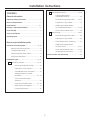 2
2
-
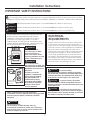 3
3
-
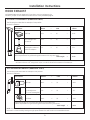 4
4
-
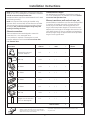 5
5
-
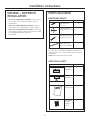 6
6
-
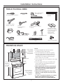 7
7
-
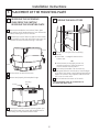 8
8
-
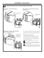 9
9
-
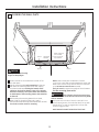 10
10
-
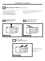 11
11
-
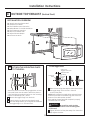 12
12
-
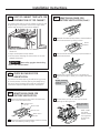 13
13
-
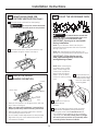 14
14
-
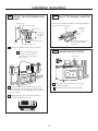 15
15
-
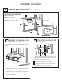 16
16
-
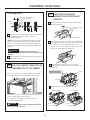 17
17
-
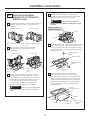 18
18
-
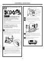 19
19
-
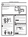 20
20
-
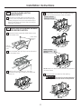 21
21
-
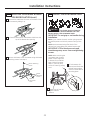 22
22
-
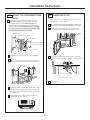 23
23
-
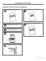 24
24
-
 25
25
-
 26
26
-
 27
27
-
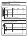 28
28
-
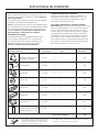 29
29
-
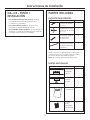 30
30
-
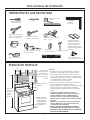 31
31
-
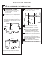 32
32
-
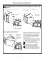 33
33
-
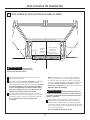 34
34
-
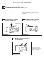 35
35
-
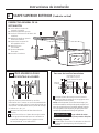 36
36
-
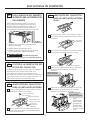 37
37
-
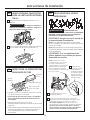 38
38
-
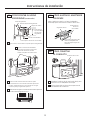 39
39
-
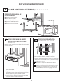 40
40
-
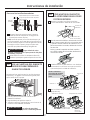 41
41
-
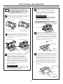 42
42
-
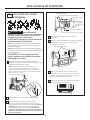 43
43
-
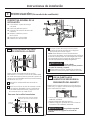 44
44
-
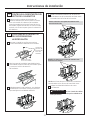 45
45
-
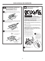 46
46
-
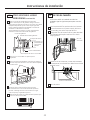 47
47
-
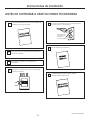 48
48


Cafe CVM9179SLSS Guía de instalación
- Categoría
- Microondas
- Tipo
- Guía de instalación
En otros idiomas
- English: Cafe CVM9179SLSS Installation guide
Otros documentos
-
GE Cafe Series DVM7195DKWW Guía de instalación
-
GE Cafe Series CVM1750SHSS Guía de instalación
-
GE CVM721M2NS5 Guía de instalación
-
GE PVM9179BLTS Guía de instalación
-
GE Appliances PNM9196SFSS Guía de instalación
-
GE PVM9005DJWW Guía de instalación
-
GE Appliances JVM3160DFCC Guía de instalación
-
Hotpoint RVM5160DH2CC Guía de instalación
-
GE JNM7196DKBB Template
-
GE CVM517P3MD1 Template