Craftsman 917286460 El manual del propietario
- Categoría
- Cortadoras de césped
- Tipo
- El manual del propietario

Operator's Manual
CRRFT$1VlRN°
GARDEN TRACTOR
26.0 HR 54" Mower
Electric Start
Automatic Transmission
Model No.
917.28646
, EspaSot, po33
This product has a low emission engine which operates
[]_ differently from previously built engines. Before start the
you
engine, read and understand this Owner's Manual.
IMPORTANT:
Read and follow all Safety
Rules and Instructions before
operating this equipment.
For answers to your questions
about this product, Call:
1-800-659-5917
Sears Craftsman Help Line
5 am - 5 pm, Mon - Sat
SEARS, ROEBUCK AND CO. HOFFMAN ESTATES, IL 60t79 U.&A,
Visit our Craftsman website:www.sear&com/craftsman

Warranty ................................................ 2
Safety Rules .......................................... 3
Product Specifications ........................... 6
Assembly/Pre-Operation ....................... 8
Operation ............................................. 13
Maintenance Schedule ........................ 21
Maintenance ........................................ 21
Service and Adjustments ..................... 26
Storage .................................................. 33
Troubleshooting .............. _.................... 34
Sears Service ........................ Back Cover
LIMITED WARRANTY ON CRAFTSMAN RIDING EQUIPMENT
For two (2) years from the date of purchase, if this Craftsman Riding Equipment is
maintained, lubricated and tuned up according to the instructions in the owner's manual,
Sears will repair or replace free of charge any parts that are found to be defective in
material or workmanship according to the guidelines of coverage listed below. Sears will
also provide free labor for these applicable warranted parts for 2 full years. During the
first 30 days of purchase, there will be no charges to service the product at your home
for issues covered by this warranty. (See exclusions below), For your convenience, tN
HOME warranty service will still be available after the first 30 days of purchase, but a trip
charge will apply. This charge will be waived if the Craftsman product is dropped off at an
authorized Sears location. For the nearest authorized Sears location, please call 1-800-4-
MY-HOME@, This warranty applies only while this product is within the United States.
THIS WARRANTY DOES NOT COVER:
• Expendable items which become worn during normal use, including but not limited to
blades, spark plugs, air cleaners, belts, and oil filters.
• Standard Maintenance Servicing, oil changes, or tune-ups
• Tire replacement or repair caused by punctures from outside objects, such as nails,
thorns, stumps, or glass.
• Repairs necessary because of operator abuse, including but not limited to, damage
caused by towing objects beyond the capability of the riding equipment, impacting
objects that bend the frame or crankshaft, or over-speeding the engine.
• Repairs necessary because of operator negligence, including but not limited to, electrical
and mechanical damage caused by improper storage, failure to use the proper grade
and amount of engine oil, failure to keep the deck clear of flammable debris, or failure to
maintain the equipment according to the instructions contained in the owner's manual,
, Engine (fuel system) cleaning or repairs caused by fuel determined to be contaminated or
oxidized (stale)° In general, fuel should be used within 30 days of its purchase date.
• Normal deterioration and wear of the exterior finishes, or product label replacement.
• Riding equipment used for commercial or rental purposes.
LIMITED WARRANTY ON BATTERY
For ninety (90) days from date of purchase, if any battery included with this riding equipment
proves defective in material or workmanship and our testing determines the battery will
not hold a charge, Sears will replace the battery at no charge, During the first 30 days of
purchase, there wilt be no charges to replace the battery at your HOME. After the first 30
days, for your convenience, IN-HOM E warranty service will stiil be available but atrip charge
wil/apply. This charge will be waived if the Craftsman product is dropped off at an authorized
Sears location. For the nearest authorized Sears location, please call 1-800-4-MY-HOME@.
This battery warranty applies only while this product is within the United States.
This warranty gives you specific legal rights, and you may also have other rights, which
vary, from state to state.
Sears, Roebuck and Co., Hoffman Estates, IL 60179

_DANGER: This cutting machine is capable of amputating hands and feet and
throwing objects. Failure to observe the following safety instructions could result
in serious injury or death.
_kWARNING: In order to prevent ac-
cidenta! starting when setting up, trans-
porting, adjusting or making repairs,
always disconnect spark plug wire and
place wire where it cannot contact spark
plug.
_IbWARNING: Do not coast down a hill in
neutral, you may lose control of the tractor.
_,WARNING; Tow only the attachments
that are recommended by and comply with
specifications of the manufacturer of your
tractor. Use common sense when towing.
Operate only at the lowest possible speed
when on a slope_ Too heavy of a load,
while on a slope, is dangerous. Tires can
lose traction with the ground and cause
you to lose control of your tractor_
_bWARNING: Engine exhaust, some of
its constituents, and certain vehicle com-
ponents contain or emit chemicals known
to the State of California to cause cancer
and birth defects or other reproductive
harm.
_WARNING: Battery posts, terminals
and related accessories contain lead and
lead compounds, chemicals known to the
State of California to cause cancer and
birth defects or other reproductive harm.
Wash hands after handling.
1. GENERAL OPERATION
• Read, understand, and follow all
instructions on the machine and in the
manual before starting,
• Do not put hands or feet near rotating
parts or under the machine. Keep clear
of the discharge opening at all times.
• Only allow responsible adults, who are
familiar with the instructions, to operate
the machine.
• Clear the area of objects such as
rocks, toys, wire, etc., which could be
picked up and thrown by the blade&
• Be sure the area is clear of bystand-
ers before operating. Stop machine if
anyone enters the area.
• Never carry passengers.
• Do not mow in reverse unless abso-
lutely necessary. Always look down
and behind before and while backing_
• Never direct discharged material
toward anyone. Avoid discharging
material against a wall or obstruction°
Material may ricochet back toward the
operator. Stop the blades when cross-
ing gravel surfaces.
• Do not operate machine without the
entire grass catcher, discharge guard,
or other safety devices in piace and
working.
• Slow down before turning.
• Never leave a running machine
unattended. Always turn off blades,
set parking brake, stop engine, and
remove keys before dismounting,
• Disengage blades when not mowing_
Shut off engine and wait for all parts to
come to a complete stop before clean-
ing the machine, removing the grass
catcher, or unclogging the discharge
guard.
• Operate machine only in daylight or
good artificial light.
• Do not operate the machine while
under the influence of alcohol or drugs.
• Watch for traffic when operating near
or crossing roadways.
• Use extra care when loading or unload-
ing the machine into a trailer or truck_
• Always wear eye protection when oper-
ating machine.
• Data indicates that operators, age 60
years and above, are involved in a
large percentage of riding mower-re-
lated injuries. These operators should
evaluate their ability to operate the
riding mower safely enough to protect
themselves and others from serious
injury.
• Followthe manufacturer's recommen-
dation for wheel weights or counter-
weights.
, Keep machine free of grass, leaves
or other debris build-up which can
touch hot exhaust / engine parts and
burn, Do not allow the mower to plow
leaves or other debris which can cause
build-up to occur_ Clean any oil or fuel
spillage before operating or storing the
machine, Allow machine to cool before
storage.

I!. SLOPE OPERATION
Slopes are a major factor related to loss of
control and tip-over accidents, which can
result in severe injury or death. Opera-
tion on all slopes requires extra caution, If
you cannot back up the slope or if you feel
uneasy on it, do not mow ito
. Mow up and down slopes, not across°
. Watch for holes, ruts, bumps, rocks, or
other hidden objects. Uneven terrain
could overturn the machine, Tall grass
can hide obstacles,
• Choose a low ground speed so that
you will not have to stop or shift while
on the slope.
• Do not mow on wet grass. Tires may
lose traction,
Always keep the machine in gear when
going down slopes. Do not shift to
neutral and coast downhill.
• Avoid starting, stopping, or turning on
a slope, if the tires lose traction, dis-
engage the blades and proceed slowly
straight down the slope.
• Keep all movement on the slopes slow
and gradual,, Do not make sudden
changes in speed or direction, which
could cause the machine to roll over,
• Use extra care while operating ma-
chine with grass catchers or other at-
tachments; they can affect the stability
of the machine. Do no use on steep
slope&
• Do not try to stabilize the machine by
putting your foot on the ground.
• Do not mow near drop-offs, ditches,
or embankments. The machine could
suddenly roll over if a wheel is over the
edge or ifthe edge caves in,
III. CHILDREN
Tragic accidents can occur if the operator
is not alert to the presence of children.
Children are often attracted to the machine
and the mowing activity, Never assume
that children will remain where you last
saw them,
• Keep children out of the mowing area
and in the watchful care of a respon-
sible adult other than the operator,
• Be alert and turn machine off if a child
enters the area.
• Before and while backing, look behind
and down for small children,
. Never carry children, even with the
blades shut off, They may fall off and
be seriously injured or interfere with
safe machine operation_ Children who
have been given rides in the past may
suddenly appear in the mowing area
for another ride and be run over or
backed over by the machine.
• Never allow children to operate the
machine.
• Use extra care when approaching blind
corners, shrubs, trees, or other objects
that may block your view of a child.
IV. TOWING
• Tow only with a machine that has a
hitch designed for towing_ Do not at*
tach towed equipment except at the
hitch poinL
• Followthe manufacturer's recom-
mendation for weight limits for towed
equipment and towing on slopes.
• Never allow children or others in or on
towed equipment.
- On slopes, the weight of the towed
equipment may cause toss of traction
and loss of control
• Travel slowly and allow extra distance
to stop.
V, SERVtCE
SAFE HANDLING OF GASOLINE
To avoid personal injury or property
damage, use extreme care in handling
gasoline. Gasoline is extremely flammable
and the vapors are explosive.
• Extinguish all cigarettes, cigars, pipes,
and other sources of ignition.
• Use only approved gasotine container,
• Never remove gas cap or add fuel with
the engine running, Allow engine to
cool before refueling.
• Never fuelthe machine indoors.
• Never store the machine or fuel con-
tainer where there is an open flame,
spark, or pilot light such as on a water
heater or other appliances,
• Never fill containers inside a vehicle
or on a truck or trailer bed with plastic
liner. Always place containers on the
ground away from your vehicle when
filling,
4

• Remove gas-powered equipment from
the truck or trailer and refuel it on the
ground. If this is not possible, then
refuel such equipment with a portable
container, rather than from a gasoline
dispenser nozzle.
• Keep the nozzle in contact with the rim
of the fuel tank or container opening at
all times until fueling is complete. Do
not use a nozzle lock-open device.
. If fuel is spilled on clothing, change
clothing immediately.
• Never overfill fuel tank. Replace gas
cap and tighten securely,
GENERAL SERVICE
• Never operate machine in a closed
area,
• Keep all nuts and bolts tight to be sure
the equipment is in safe working condi-
tion,
• Never tamper with safety devices.
Check their proper operation regularly,
• Keep machine free of grass, leaves, or
other debris build-up. Clean oil or fuel
spillage and remove any fuel-soaked
debris, Allow machine to cool before
storing.
, If you strike a foreign object, stop and
inspect the machineo Repair, if neces-
sary, before restarting-
. Never make any adjustments or repairs
with the engine running,
• Check grass catcher components and
the discharge guard frequently and
replace with manufacturer's recom-
mended parts, when necessary,
• Mower blades are sharp, Wrap the
blade or wear gloves, and use extra
caution when servicing them,
• Check brake operation frequently. Ad-
just and service as required.
• Maintain or replace safety and instruc-
tion labels, as necessary.
• Be sure the area is clear of bystand-
ers before operating, Stop machine if
anyone enters the area.
• Never carry passengers.
• Do not mow in reverse unless abso-
lutely necessary, Always took down
and behind before and while backing,
• Never carry children, even with the
blades shut off, They may fall off and
be seriously injured or interfere with
safe machine operation. Children who
have been given rides in the past may
suddenly appear in the mowing area
for another ride and be run over or
backed over by the machine.
• Keep children out of the mowing area
and in the watchful care of a respon-
sible adutt other than the operator,
• Be alert and turn machine off if a child
enters the area.
• Before and while backing, look behind
and down for small children,
• Mow up and down slopes (15 ° Max),
not across,
• Choose a low ground speed so that
you will not have to stop or shift while
on the slope.
• Avoid starting, stopping, or turning on
a slope. If the tires lose traction, dis-
engage the blades and proceed slowly
straight down the slope.
• if machine stops while going uphill,
disengage blades, shift into reverse
and back down slowly.
• Do not turn on slopes unless neces-
sary, and then, turn slowly and gradu-
ally downhill, if possible.
5

PRODUCT SPECIFICATIONS
Gasoline Capacity 40 Gallons
and Type: Unleaded Regular
Oil Type SAE 30 (above 32°F)
(API-SG-SL): SAE 5W30 (below 32°F
Oil Capacity: 61 oz,
Spark Plug: Champion RC12YC
(Gap: .030")
Ground Speed Forward: 0-5.5
Reverse: 0-2_4
Charging System: 15 Amps
Battery: Amp/Hr: 35
Min, CCA: 280
Case size: UtR
Blade Bolt Torque: 45-55 Ft, Lbs,
CONGRATULATIONS on your purchase
of a new tractor, it has been designed,
engineered and manufactured to give
you the best possible dependability and
performance°
Should you experience any problem you
cannot easily remedy, please contact a
Sears or other qualified service center.
We have competent, well-trained repre-
sentatives and the proper tools to service
or repair this tractor,
Please read and retain this manual. The
instructions will enable you to assemble
and maintain your tractor properly. Always
observe the "SAFETY RULES".
CUSTOMER RESPONSIBILITIES
• Read and observe the safety rules.
. Follow a regular schedule in main-
taining, caring for and using your tractor.
• Follow the instructions under "Mainte-
nance" and "Storage" sections of this
owneCs manual,
_IbWARNING" This tractor is equipped
with an internal combustion engine and
should not be used on or near any unim-
proved forest-covered, brush-covered or
grass-covered land unless the engine's
exhaust system is equipped with a spark
arrester meeting applicable local or state
laws (if any), If a spark arrester is used, it
should be maintained in effective working
order by the operator.
in the state of California the above is
required by law (Section 4442 of the
California Public Resources Code), Other
states may have similar laws. Federal
laws apply on federal lands, A spark at-
rester for the muffler is available through
your nearest Sears service center (See
REPAIR PARTS manual).
REPAIR PROTECTION
AGREEMENTS
Congratulations on making a smart pur-
chase, Your new Craftsman® product is
designed and manufactured for years of
dependable operation, But like all products,
it may require repair from time to time. That's
when having a Repair Protection Agreement
can save you money and aggravation.
Purchase a Repair Protection Agreement
now and protect yourseff from unexpected
hassle and expense.
Here's what's included in the Agreement:
• Expert service by our 12,000 profe-
siona! repair specialists.
• Unlimited service and no charge for
parts and labor on all covered repairs.
• Product replacement if your covered
product can't be fixed.
. Discount of 10% from regular price of
service and service-related parts not
covered by the agreement; also, 10%
off regular price of preventive mainte-
nance check.
• Fast help by phone- phone sup-
port from a Sears representative on
products requiring in-home repair, plus
convenient repair scheduling,
Once you purchase the Agreement, a
simple phone call is all that it takes for you
to schedule service. You can call anytime
day or night, or schedule a service ap-
pointment online,
Sears has over 12,000 professional repair
specialists, who have access to over 4,5
million quality parts and accessories,
That's the kind of professionalism you can
count on to help prolong the life of your
new purchase for years to come. Purchase
your Repair Protection Agreement today!
Some limitations and exclusions apply,
For prices and additional information
call 1-800-827-6655,
SEARS INSTALLATION SERVICE
For Sears professional installation of home
appliances, garage door openers, water
heaters, and other major home items, in
the USA. call 1-800-4-MY-HOME®

(1) Wheel
Mower Front Wheel
(1) 1-1/40,D. Washer
Q
(1) Locknut 3/8-16
(5) Large Retainer
Springs - 7/16
(2) Small Retainer
Springs - 5/16
(5) t-3/16 O,D. Washers
Mower
(1) 314O.D. Washers
(1) Front Link
_y
_" (t) Anti-Swar Bar
_'-_ (2) Rear Lift Link
Assemblies
(1) Oil Drain Tube
For Future Use
(2) Keys
Mowerl,_t_.Sheet._.llnstalllS_
7

Your new tractor has been assembled at the factory with the exception of those parts left
unassembled for shipping purposes,
TOOLS REQUIRED FOR
ASSEMBLY
A socket wrench set will make assembly
easier. Standard wrench sizes you need
are listed below,
(1) 3/4"wrench (1) Pliers
(1) 9/16" wrench (1) Utility knife
(1) Tire pressure gauge
ADJUST SEAT
1. Sit in seat.
2, Lift up adjustment lever (A) and slide seat
until a comfortable position is reached
which allows you to press c_utch/brake
pedal all the way down_
3_ Release lever to lock seat in position,
When right or left hand is mentioned in this
manual, it means, from your point of view,
when you are in the operating position (seat-
ed behind the steering whee!).
TO REMOVE TRACTOR FROM
CARTON
UNPACK CARTON
1, Remove all accessible loose parts and
parts cartons from carton.
2, Cut along dashed lines on all four panels
of carton. Remove end panels and lay
side panels flat,
3_ Remove mower and packing materials.
4. Check for any additional loose aprts or
cartons and remove,
CHECK BATTERY
1. Lift hood to raised position.
NOTE: If this battery is put into service after
month and year indicated on label (L) (label
islocated between terminals) charge battery
for minimum of one hour at 6-! 0 amp& (See
"BATTERY" in Maintenance section of this
manual for charging instructions).
\
NOTE; You may now roll o rd dve you rtractor
offtheskid, Followthe appropriate instruction
below to remove the tractor from the skid,
z_
,a_ WARNING: Before starting, read, un-
derstand and follow all instructions in the
Operation section of this manual Be sure
tractor is in a wellwentilated area. Be sure
the area in front of tractor is clear of other
people and objects.
TO ROLL TRACTOR OFF SKID
(See Operation section for location
and function of controls)
1o Raise attachment lift lever to its highest
position,
2_ Release parking brake by depressing
brake pedal,
3. Place freewheel control in "transmission
disengaged position" (See "TO TRANS-
PORT" in the Operation section of this
manual).
4, Roll tractor forward off skid.
8

TO DRIVE TRACTOR OFF SKID
(See Operation section for location
and function of controls)
1. Be sure all the above steps have been
completed,,
2, Check engine oil level and fill fuel tank
with gasoline.
3. Place freewheel control in "transmission
engaged" position (see "TO TRANS-
PORT" in Operation section of this
manual).
4. Siton seat in operating position, depress
brake pedal and set the parking brake,
5. Raise attachment lift lever to its highest
position.
6. Remove key from bag and start the en-
gine (see "TO START ENGINE" in the
Operation section of this manual). After
engine has started, move throttle control
to idle position.
7, Release parking brake.
8, Slowly depress forward drive pedal and
drive tractor off skid°
9. Apply brake to stop tractor and set park-
ing brake.
10.Turn ignition key to "STOP" position.
Continuewiththe instructions that follow.
ASSEMBLE FRONT WHEEL TO
MOWER
I, Using shoulder bolt, washer and Iocknut
from parts bag, assemble front wheel to
mower as shown, Tighten securely,
CAUTION: Lift lever is spring loaded,
Have a tight grip on lift lever, lower it slowly
and engage in lowest position,
2, Turn steering wheel to the left as far as it
will go and position mower on right side of
tractor with deflector shield to the right,
i
3. Remove plastic tie securing belt, bring
belt forward and check belt for proper
routing in all mower pulley grooves.
NOTE; Be sure mower side suspension
arms (A) are pointing forward before sliding
mower under tractor°
INSTALL MOWER AND DRIVE
BELT
See MOWERAN D DRIVE BELT ASSEMBLY
Supplement Sheet for additional guidance
on this assembly.
Be sure tractor ison level surface and engage
parking brake.
I, Lower attachment lift lever to its lowest
position,
4_
5-
Slide mower under tractor until it is cen-
tered under tractor,
FIRST INSTALL ANTI-SWAY BAR (S).
- From right side of mower, insert ant-sway
bar into hole in transmission bracket (T).
- Pivot bar towards you and insert other
end of bar into hole in rear mower bracket
(D), Move mower as needed to insert bar.
- Secure with washer and retainer spring
as shown.

9. Repeatonoppositesideoftractor,
10.Turnsteeringwheelto positionwheels
straightforward,
1I_ATTACHFRONTLINK(E)- Workfrom
leftsideof tractor,Insertrodendof link
assemblythroughfront hole in tractor
frontsuspensionbracket(F)andsecure
withretainerspring(G)throughholeinlink
locatedbehindthebracket,
12,Insertotherendoflink(E)intoholeinfront
mowerbracket(H)andsecurewithwasher
andretainerspring(J),
6_ ATTACHMOWERSIDESUSPENSION
ARMS(A)TOCHASSIS-Positionhole
in armoverpin (B)onoutsideoftractor
chassisand secure with washerand
retainerspring_
7_
&
Repeat on opposite side of tractor.
ATTACH REAR LIFT LINKS (C) - Insert
rod end of link assembly into hole in tractor
lift shaft suspension arm (L) and pivot link
down to mower. Lift rear corner of mower
and position slot in link assembly over pin
on rear mower bracket (D) and secure with
washer and retainer spring,
13. Disengage befttension rod (K) from locking
bracket (L),
14, Install belt onto engine clutch pulley (M).
IMPORTANT" Check belt for proper routing
in all mower pulley grooves,
10

15, Engage belt tension rod (K) on locking
, bracket (L).
_,CAUTION: Belttension rod is spring loaded,
Have a tight grip on rod and engage slowly.
16, Raise attachment lift lever to highest posi-
tion,
17, If necessary, adjust gauge wheels before
operating mower as shown in the Opera-
tion section of this manual,
02937
!1

CHECK TIRE PRESSURE
Thetires onyourtractorwere overinflated atthe
factoryforshipping purposes. Correcttire pres-
sure is importantfor best cutting performance.
• Reduce tire pressure to PSI shown on tires.
CHECK DECK LEVELNESS
For best cutting results, mower housing
should be properly leveled. See "TO LEVEL
MOWER" in the Service and Adjustments
section of this manual.
CHECK FOR PROPER POSITION
OF ALL BELTS
See the figures that are shown for replac-
ing motion and mower blade drive belts in
the Service and Adjustments section of this
manual. Verify that the belts are routed
correctly,
CHECK BRAKE SYSTEM
After you learn how to operate your tractor,
check to see that the brake is operating
properly, See "TO CHECK BRAKE" in the
Service and Adjustments section of this
manual,
,/'CHECKLIST
Before you operate your new tractor, we
wish to assure that you receive the best
performance and satisfaction from this
Quality Product.
Please review the following checklist:
v" All assembly instructions have been com-
pleted.
v" No remaining loose parts in carton_
v" Battery is properly prepared and charged.
v" Seat is adjusted comfortably and tightened
securely.
¢" All tires are properly inflated, (For shipping
purposes, the tires were overinflated at
the factory).
¢" Besure mowerdeckis properlyleveledside-
to-side/front-to-rearfor best cutting results.
(Tires must be properly inflated for leveling).
,/Check mower and drive belts, Be sure
they are routed properly around pulleys
and inside all belt keepers.
z" Checkwiring. Seethat all connectionsare
still secure and wires are properly clamped,
v" Before driving 
These symbols may appear on your tractor or in literature supplied with the product.
Learn and understand their meaning.
R N H L
REVERSE NEUTRAL HIGH LOW
6 6
ENGINE OFF REVERSE F.NG_NEON ENGINE START
OPERATION
SYSTEMIRes)
- N I;
LIGHTS ON FUEL BATTERY REVERSE
ATTACHMENT ATTACHMENT
CLUTCH DISENGAGED CLUTCH ENGAGED
FREE WHEEL
(AutomeUc Models only)
I'-,I
CHOKE FAST SLOW
(@)
PARKINGBRAKE MOWERHEIGHT
IGNITION SWRCH
MOWER LIFT
;I;
FORWARD
DANGER, KEEP HANDS
AND FEET AWAY
CRUISE CONTROL
CLUTCH_RAKE
PEDAL
@@®@@
KEEP AREA CLEAR SLOPE HAZARDS
_EESAFETYRULESSECTION|
&
Failure to follow Instructions
could result in serious injury or
death_ The safety alert symbol
is used to identify safety inform-
ation about hazards which can
result tn death, serious injury
and/or property damage.
DANGER Indicates a hazard which,if not avotded,
will result In death or serious Injury,
WARNING indicatesa hazardwhtch, Ifnot avoided,
could result In death or serious Injury.
CAUTION indicatesa hazard which, ifnot avoided,
mightresult In minor or moderate Injury.
CAUTION whenused without thealert symbol,
Indicatesa situationthatcould resultin damage
tothe tractor and/or engine.
HOT SURFACES indicatesa hazardwhich,
ifnot avoided, could result In death, serious injury
and/or property damage.
FIRE indicatesa hazardwhich,if notavoided,
could result In death, serious Injuryand/or
property damage.
13

KNOW YOUR TRACTOR
READ THIS OWNER'S MANUAL AND SAFETY RULES BEFORE OPERATING YOUR
TRACTOR
Compare the illustrations with your tractor to familiarize yourself with the locations of
various controls and adjustment& Save this manual for future reference.
03 t 24
Our tractors conform to the applicable safety standards of the
American National Standards Institute.
(A) ATTACHMENT LIFT LEVER - Used
to raise and lower the mower or other at-
tachments mounted to your tractor°
(B) BRAKE PEDAL - Used for braking the
tractor and starting the engine.
(C) PARKING BRAKE - Locks clutch/
brake pedal into the brake position,
(D) THROTTLE CONTROL - Used to
control engine speed.
(E) ATTACHMENT CLUTCH LEVER
- Used to engage the mower blades, or
other attachments mounted to your tractor,
(F) IGNITION SWITCH - Used for starting
and stopping the engine,
(G) REVERSE OPERATION SYSTEM
(ROS) "ON" POSITION - Allows opera-
tion of mower or other powered attach-
ment while in reverse.
(H) LIGHT SWITCH - Turns the head-
lights on and off.
(J) CRUISE CONTROL LEVER - Used to
set forward movement of tractor at desired
speed without holding the forward drive
pedal,
(K) FORWARD DRIVE PEDAL - Used for
forward movement of tractor°
(L) REVERSE DRIVE PEDAL - Used for
reverse movement of tractor,
(M) FREEWHEEL CONTROL- Disen-
gages transmission for pushing or slowly
towing the tractor with the engine off,
(N) CHOKE CONTROL - Used when
starting a cold engine.
(P) SERVICE REMINDER / HOUR METER
- Indicates when service is required for
the engine and mower.
(Q) 12-VOLT POWER PORT - Used for
12-volt accessories.
14

The operation of any tractor can result in foreign objects thrown into the
eyes, which can result in severe eye damage. Always wear safety glasses
or eye shields while operating your tractor or performing any adjustments
or repairs, We recommend standard safety glasses or a wide vision safety
mask worn over spectacles.
HOW TO USE YOUR TRACTOR
TO SET PARKING BRAKE
Your tractor is equipped with an operator
presence sensing switch° When engine
is running, any attempt by the operator
to leave the seat without first setting the
parking brake will shut off the engine
t_ Depress brake pedal (B) all the way
down and hold.
2. Pull parking brake lever (C) up and
hold, release pressure from brake
pedal (B), then release parking brake
lever, Pedal should remain in brake
position, Make sure parking brake will
hold tractor secure.
GROUND DRIVE -
• To stop ground drive, depress brake
pedal all the way down
ENGINE -
• Move throttle control (D) between half
and full speed (fast) position,
NOTE: Failure to move throttle control
between half and full speed (fast) posF
tion, before stopping, may cause engine to
"backfire".
• Turn ignition key (F) to "STOP" position
and remove key. Always remove key
when leaving tractor to prevent unau-
thorized use,
• Never use choke (N) to stop engine.
IMPORTANT; Leaving the ignition switch in
any position other than "STOP" will cause
the battery to discharge and go dead.
NOTE; Under certain conditions when
tractor is standing idle with the engine run-
ning, hot engine exhaust gases may cause
"browning" of grass. To eliminate this pos-
sibility, always stop engine when stopping
tractor on grass areas,
AI_OAUTION: Always stop tractor com-
pletely, as described above, before leaving
the operator's position.
STOPPING
MOWER BLADES -
• To stop mower blades, move at-
tachment clutch lever in to disengaged
position (r_).
(r_i) Attachment
Clutch
Engage Position
(1_) Disengaged
Position
15

TO USE CHOKE CONTROL (N)
Use choke control whenever you are start-
ing a cold engine. Do not use to start a
warm engine°
• To engage choke control, pull knob out.
Slowly push knob in to disengage,
TO MOVE FORWARD AND
BAG KWAR D
The direction and speed of movement is
controlled by the forward and reverse drive
pedals.
1_ Start tractor and release parking brake,
2. Slowly depress forward (K) or reverse
(L) drive pedal to begin movement.
Ground speed increases the further
down the pedal is depresse&
03124
TO USE CRUISE CONTROL
The cruise control feature can be used for
forward travel only,
SYSTEM CHARACTERISTICS
The cruise control should only be used
while mowing or transporting on relatively
smooth, straight surfaces, Other conditions
such as trimming at slow speeds may
cause the cruise control to disengage. Do
not use the cruise control on slopes, rough
terrian or while trimmimg or turning.
° With forward drive pedal (K) depressed
to desired speed, pull cruise control
lever (J) up and hold while lifting your
foot off the pedal, then release the lever,
To disengage the cruise control, depress
the brake pedal or tap on forward drive
pedal,
TO ADJUST MOWER CUTTING HEIGHT
The position of the attachment lift lever (A)
determines the cutting height.
• Put attachment lift lever in desired cut-
ting height slot.
• Slide pointer tab (T) to desired cutting
height as a reminder for next time you
mow.
The cutting height range is approxi-
mately 1" to 4", The heights are mea-
sured from the ground to the blade tip with
the engine not running. These heights
are approximate and may vary depending
upon soil conditions, height of grass and
types of grass being mowed°
• The average lawn should be cut to ap-
proximately 2-I/2 inches during the cool
season and to over 3 inches during hot
months. For healthier and better look-
ing lawns, mow often and after moderate
growth.
• For best cutting performance, grass
over 6 inches in height should be
mowed twice, Make the first cut rela-
tively high; the second to desired heighL
16

TO ADJUST GAUGE WHEELS
Gauge wheels are properly adjusted
when they are slightly off the ground when
mower is at the desired cutting height in
operating position. Gauge wheels then
keep the deck in proper position to help
prevent scalping in most terrain conditions.
NOTE: Adjust gauge wheels with tractor
on a flat level surface.
1. Adjust mower to desired cutting height
(See "TO ADJUST MOWER CUTTING
HEIGHT" in this section of manual).
2, With mower in desired height of cut
position, gauge wheels should be
assembled so they are slightly off the
ground, Install gauge wheel in appro-
priate hole. Tighten securely-
3 Repeat for all, installing gauge wheel in
same adjustment hole.
TO OPERATE MOWER
Your tractor is equipped with an operator
presence sensing switch. Any attempt
by the operator to leave the seat with the
engine running and the attachment clutch
engaged will shut off the engine. You must
remain fully and centrally positioned in the
seat to prevent the engine from hesitating
or cutting off when operating your equip-
ment on rough, rolling terrain or hills,
1, Select desired height of cut with at-
tachment lift lever°
2, Start mower blades by engaging at-
tachment clutch control,
TO STOP MOWER BLADES -
disengage attachment clutch control.
CAUTION: Do not operate the mower
without either the entire grass catcher,
on mowers so equipped, or the deflector
shield (S) in place.
REVERSE OPERATION SYSTEM (ROS)
Your tractor is equipped with a Reverse
Operation System (ROS), Any attempt by
the operator to travel in the reverse direc-
tion with the attachment clutch engaged
will shut off the engine unless ignition key
is placed in the ROS "ON" position.
_LWARNING: Backing up with the at-
tachment clutch engaged while mowing
is strongly discouraged. Turning the ROS
"ON", to allow reverse operation with the
attachment clutch engaged, should only
be done when the operator decides it is
necessary to reposition the machine with
the attachment engage& Do not mow in
reverse unless absolutely necessary.
USING THE REVERSE OPERATION
SYSTEM -
Only use if you are certain no children or
other bystanders will enter the mowing
area,
1, Depress brake pedal all the way down.
2. With engine running, turn ignition key
counterclockwise to ROS "ON" posi-
tion,
3. Look down and behind before and
while backing.
4. Slowly depress reverse drive pedal to
start movement.
5, When use of the ROS is no longer
needed, turn the ignition key clockwise
to engine "ON" position.
ROS "ON" Position Engine "ON" Position
(Normal Operating)
'17

OPERATE ON HILLS
ARNING: Do not drive up or down
hills with slopes greater than 15 ° and do
not drive across any slope. Use the slope
guide provided at the back of this manual.
, Choose the slowest speed before start-
ing up or down hills.
• Avoid stopping or changing speed on
hills.
• If stopping is absolutely necessary, push
brake pedal quickly to brake position
and engage parking brake.
• To restart movement, slowly release
parking brake and brake pedal.
• Slowly depress appropriate drive pedal
to slowest setting,
• Make all turns slowly.
TO TRANSPORT
When pushing or towing your tractor, be
sure to disengage transmission by placing
freewheel control in freewheeling position.
Freewheel control is located at the rear
drawbar of tractor.
!. Raise attachment lift lever to its highest
position.
2_ Pull freewheel control out and into the
slot and release so it is held in the
disengaged position,
• Do not push or tow tractor at more than
two (2) MPH.
• To re-engage transmission, reverse
above procedure.
Transmission Enc _ed
Transmission Disengaged
NOTE: To protect hood from damage when
transporting your tractor on a truck or a
trailer, be sure hood is closed and secured
to tractor Use an appropriate means of
tying hood to tractor (rope, cord, etc),
TOWING CARTS AND OTHER ATTACH-
MENTS
Tow only the attachments that are recom-
mendedby and comply with specifications
of the manufacturer of your tractor, Use
common sense when towing. Too heavy
of a load, while on a slope, is dangerous.
Tires can lose traction with the ground and
cause you to lose control of your tractor,
SERVICE REMINDER/HOUR METER
Service reminder shows the total number
of hours the engine has run and flashes to
indicate that the engine or mower needs
servicing. When service is required, the
service reminder will flash for two hours.
To service engine and mower, see the
Maintenance section of this manual.
NOTE: Service reminder runs when the
ignition key is in any position but "STOP".
For accurate reading, be sure key remains
in the "STOP" position when engine is not
running_
BEFORE STARTING THE ENGINE
CHECK ENGINE OIL LEVEL
The engine in your tractor has been
shipped, from the factory, already filled
with summer weight oil.
i. Check engine oil with tractor on level
ground,
2, Remove oil fill cap/dipstick and wipe
clean, reinsert the dipstick and screw
cap tight, wait for a few seconds, re-
move and read oil level. If necessary,
add oil until "FULL' mark on dipstick is
reached. Do not overfill,
• For cold weather operation you should
change oil for easier starting (See the
oil viscosity chart in the Maintenance
section of this manual).
• To change engine oil, see the Mainte-
nance section in this manual.
ADD GASOLINE
• Fill fuel tank to bottom of filler neck. Do
not overfill Use fresh, clean, regular
unleaded gasoline with a minimum of
87 octane. (Use of leaded gasoline wilt
increase carbon and lead oxide deposits
and reduce valve life). Do not mix oil
with gasoline. Purchase fuel in quan-
tities that can be used within 30 days to
assure fuel freshness,
18

Aq,CAUTION: Wipe off any spilled oil or
fuel. Do not store, spill or use gasoline
near an open flame.
IMPORTANT: When operating in temper-
atures below32°F(0°C), use fresh, clean
winter grade gasoIine to help insure good
cold weather starting.
CAUTION: Alcohol blended fuels (called
gasohol or using ethanol or methanol) can
attract moisture which leads to separation
and formation of acids during storage,
Acidic gas can damage the fuel system
of an engine while in storage. To avoid
engine problems, the fuel system should
be emptied before storage of 30 days
or longer. Drain the gas tank, start the
engine and let it run until the fuel lines
and carburetor are empty. Use fresh fuel
next season. See Storage Instructions for
additional information Never use engine
or carburetor cleaner products in the fue!
tank or permanent damage may occur,
TO START ENGINE
When starting the engine for the first time
or if the engine has run out of fuel, it will
take extra cranking time to move fuel from
the tank to the engine.
1, Be sure freewheel control is in the
transmission engaged position.
2. Sit on seat in operating position,
depress brake pedal and set parking
brake.
3. Move attachment clutch to disengaged
position.
4, Move throttle control to fast position
5. Pull choke control out for a coid engine
start attempt. For a warm engine start
attempt the choke control may not be
needed.
NOTE: Before starting, read the warm and
cold starting procedures below.
6. Insert key into ignition and turn key
clockwise to start position and release
key as soon as engine starts, Do not
run starter continuously for more than
fifteen seconds per minute, if the
engine does net start after several
attempts, push choke control in, wait
a few minutes and try again. If engine
still does not start, pull the choke con-
trol out and retry.
WARM WEATHER STARTING (50 ° F and
above)
7. When engine starts, slowly push choke
control in until the engine begins to
run smoothly, If the engine starts to
run roughly, pull the choke control out
slightly for a few seconds and then
continue to push the control in slowly.
• The attachments and ground drive can
now be used. tf the engine does not
accept the load, restart the engine and
allow it to warm up for one minute using
the choke as described above.
COLD WEATHER STARTING (50 ° F and
below)
7. When engine starts, slowly push choke
control in until the engine begins to run
smoothly. Continue to push the choke
control in small steps allowing the en-
gine to accept small changes in speed
and load, until the choke control is futly
in. If the engine starts to run rougHy,
pull the choke control out slightly for a
few seconds and then continue to push
the control in slowly. This may require
an engine warm-up period from several
seconds to several minutes, depending
on the temperature_
AUTOMATIC TRANSMISSION WARM UP
Before driving the unit in cold weather,
the transmission should be warmed up as
follows:
1, Be sure the tractor is on level ground,
2. Release the parking brake and let the
brake slowly return to operating posi-
tion,
3, Allow one minute for transmission to
warm up. This can be done during the
engine warm up period.
• The attachments can be used during
the engine warm-up period after the
transmission has been warmed up and
may require the choke control be pulled
out slightly.
NOTE; If at a high altitude (above 3000
feet) or in cold temperatures (below 32 F)
the carburetor fuel mixture may need to
be adjusted for best engine performance
(see "TO ADJUST CARBURETOR" in the
Service and Adjustments section of this
manual),
19

PURGE TRANSMISSION
_,CAUTION: Never engage or dis-
engage freewheel lever while the engine
is running.
To ensure proper operation and per-
formance, it is recommended that the
transmission be purged before operating
tractor for the first time. This procedure wil!
remove any trapped air inside the trans-
mission which may have developed during
shipping of your tractor.
IMPORTANT: Should your transmission
require removal for service or replace-
ment, it should be purged after reinstall-
ation before operating the tractor.
1. Place tractor safely on a ievel surface
- that is clear of objects and open - with
engine off and parking brake set_
2, Disengage transmission by placing
freewheel control in disengaged posi-
tion (See "TO TRANSPORT" in this
section of manual)°
3. Sitting in the tractor seat, start engine,
After the engine is running, move
throttle control to slow position, Disen-
_gage parking brake,
CAUTION: At any time, during step
4, there may be movement of the drive
wheels,
4_ Depress forward drive pedal to full
forward position and hold for five (5)
seconds and release pedal, Depress
reverse drive pedal to full reverse posi-
tion and hold for five (5) seconds and
release pedal. Repeat this procedure
three (3) times.
5. Shutoff engine and set parking brake.
6. Engage transmission by placing free-
wheel control in engaged position (See
"TO TRANSPORT" in this section of
manual).
7, Sitting in the tractor seat, start engine.
After the engine is running, move
throttle control to half (l/2) speed.
Disengage parking brake.
8, Drive tractor forward for approximately
five feet then backwards for five feet.
Repeat this driving procedure three
times,
Your transmission is now purged and now
ready for normal operation.
MOWING TIPS
• Tire chains cannot be used when the
mower housing is attached to tractor.
• Mower should be properly leveled for
best mowing performance. See "TO
LEVEL MOWER HOUSING" in the
Service and Adjustments section of this
manual
• The left hand side of mower should be
used for trimming.
• Drive so that clippings are discharged
onto the area that has already been
cut. Have the cut area to the right of
the tractor. This will result in a more
even distribution of clippings and more
uniform cutting,
• When mowing large areas, start by
turning to the right so that clippings wii!
discharge away from shrubs, fences,
driveways, etc. After one or two rounds,
mow in the opposite direction making
left hand turns until finished.
f
1
• tf grass is extremely talt, it should be
mowed twice to reduce load and pos-
sible fire hazard from dried clippings.
Make first cut relatively high; the second
to the desired height,
• Do not mow grass when it is wet°
Wet grass will plug mower and leave
undesirable clumps. Allow grass to dry
before mowing.
• Always operate engine at full throttle
when mowing to assure better mowing
performance and proper discharge of
material, Regulate ground speed by
selecting a low enough speed to give
the mower cutting performance as well
as the quality of cut desired.
• When operating attachments, select a
ground speed that will suit the terrain
and give best performance of the at-
tachment being used,
20

MAINTENANCE BEFORE EVERY EVERY EVERY EVERY EVERY BEFORE
SCHEDULE EACH B 25 50 100 sEASON STORAGE
USE HOURS HOURS HOURS HOURS
iiiiii
Check Brake Operation tf If
T Check Tire Pressure if V _
A Chec.k [or Loose Fasteners If .........................If .........
C Chec!dRepIace Mower Blades V'_
T Lubrication Chart V _
0 Check Battery Level I_
R
Check Transaxle Cooling
Check Mower Levelness
Check V-Befts
iii iiiii iiiii i ii i
Check En,glne Oil Level
D_anqaEnFlneO (wthe f er)
p: 3hange Engine Oil Iwll!_ou[ oil filler
N"'!i;a;AiiFiiie, I
.,.,lean Air Screen
I rns_ect Muffler/SparkArrester
U iReplace 011Filter {If equipped)
J I
iE, glean Engine Cooling Fins
i ! ......
%place Air Filler Paper Caflddge
i/
i/
, ,"" _I ,_t
J_
11"
i/
v"
v'
I_T,2
' v' ' V ....
V'
1 - Change mere often when operating under a heavy load or
Inhigh ambient temperatures
2 - Service more Often when operating In dirty or dusly cendilions
3 - Replace blades more often when mewing in sandy Boll
,1., Net requited If equipped with maleleeance-lree battery
GENERAL RECOMMENDATIONS
The warranty on this tractor does not
cover items that have been subjected to
operator abuse or negligence. To receive
full value from the warranty, operator
must maintain tractor as instructed in this
manual.
Some adjustments will need to be made
periodically to properly maintain your
tractor.
At least once a season, check to see if
you should make any of the adjustments
described in the Service and Adjustments
section of this manual.
• At least once a year you should replace
the spark plug, clean or replace air filter,
and check blades and belts for wear,
A new spark plug and clean air filter
assure proper air-fuel mixture and help
your engine run better and last longer,
BEFORE EACH USE
1, Check engine oil level°
2, Check brake operation,
3. Check tire pressure,
4, Check operator presence and
ROS systems for proper operation
5, Check for loose fasteners,
LUBRICATION CHART
iT)Spindle Spindle
Zerk Zerk
Front Wheel
(J) Front Bearing Zerk
Bearing Zerk
_ Engine
q) Steering
Sector Gear
Teeth
(])General Purpose Grease
(_)Refer to Maintenance "ENGINE" Section
IMPORTANT: Do not oil or grease the
pivot points which have special nylon
bearings, Viscous lubricants will attract
dust and dirt that will shorten the life of the
self-lubricating bearings. If you feel they
must be lubricated, use only a dry, pow-
dered graphite type lubricant sparingly,
21

TRACTOR
Always observe safety rules when per-
forming any maintenance,
BRAKE OPERATION
If tractor requires more than five (5) feet to
stop at highest speed in highest gear on a
level, dry concrete or paved surface, then
brake must be serviced. (See "TO CHECK
BRAKE" in the Service and Adjustments
section of this manual),
TIRES
• Maintain proper air pressure in all tires
(See PSI on tires),
• Keep tires free of gasoline, oil, or insect
control chemicals which can harm rubber.
• Avoid stumps, stones, deep ruts, sharp
objects and other hazards that may
cause tire damage,
NOTE: To seal tire punctures and prevent
fiat tires due to slow leaks, tire sealant
may be purchased from your local parts
dealer. Tire sealant also prevents tire dry
rot and corrosion,
OPERATOR PRESENCE SYSTEM AND
REVERSE OPERATION SYSTEM (ROS)
Be sure operator presence and reverse
operation systems are working properly. If
your tractor does not function as de-
scribed, repair the problem immediately,
• The engine should not start unless the
brake pedal is fully depressed, and the
attachment clutch control is in the disen-
gaged position.
CHECK OPERATOR PRESENCE
SYSTEM
. When the engine is running, any at-
tempt by the operator to leave the seat
without first setting the parking brake
should shut off the engine.
• When the engine is running and the
attachment clutch is engaged, any at-
tempt by the operator to leave the seat
should shut off the engine.
• The attachment clutch should never op-
erate unless the operator is in the seat,
CHECK REVERSE OPERATION (ROS)
SYSTEM
• When the engine is running with the
ignition switch in the engine "ON" posi-
tion and the attachment clutch engaged,
any attempt by the operator to drive in
reverse should shut off the engine,
- When the engine is runnin,_ wi!h the
ignition switch in the ROS ON position
and the attachment clutch engaged,
any attempt by the operator to drive in
reverse should NOT shut off the engine,
BLADE CARE
For best results mower blades must be
sharp. Replace worn, bent or damaged
blade&
A CAUTION: Use only a replacement
blade approved by the manufacturer of
your tractor. Using a blade not approved
by the manufacturer of your tractor is
hazardous, could damage your tractor and
void your warranty,
ROS "ON" Position Engine "ON" Position
(Normal Operating)
BLADE REMOVAL
1. Raise mower to highest position to al-
low access to blades,
NOTE: Protect your hands with gloves
and/or wrap blade with heavy cloth,
2, Remove blade bolt by turning counter-
clockwise,
3, Install new blade with stamped
"GRASS SIDE" facing the ground,
IMPORTANT: To ensure proper assembly,
center hole in blade must align with star
on mandrel assembly,
4, Install and tighten blade bolt securely
(45_55 Ft. Lbs, torque),
IMPORTANT: Special blade bolt is heat
treated,
Mandrel
Assembly
22
Blade
"Star
Center Hole 4,

BATTERY
Your tractor has a battery charging system
which is sufficient for normal use, How-
ever, periodic charging of the battery with
an automotive charger will extend its life_
• Keep battery and terminals clean,
• Keep battery bolts tight,
• Keep small vent holes open.
• Recharge at 6-t0 amperes for I hour,
NOTE: The original equipment battery on
your tractor is maintenance free, Do not
attempt to open or remove caps or covers,
Adding or checking level of eiectrotyte is
not necessary.
TO CLEAN BATTERY AND TERMINALS
Corrosion and dirt on the battery and termi-
nals can cause the battery to "leak" power_
1o Disconnect BLACK battery cable first
then RED battery cable and remove
battery from tractor,
2, Rinse the battery with plain water and
dry.
3, Clean terminals and battery cable ends
with wire brush until bright,
4, Coat terminals with grease or petro-
leum jelly.
5, Reinstall battery (See "REPLACING
BATTERY in the SERVICE AND AD-
JUSTMENTS section of this manual)_
TRANSAXLE COOLING
The transmission fan and cooling fins
should be kept clean to assure proper
cooling,
Do not attempt to clean fan or transmis-
sion while engine is running or while the
transmission is hot, To prevent possible
damage to seals, do not use high pressure
water or steam to clean transaxle,
• Inspect cooling fan to be sure fan blades
are intact and clean,
• Inspect cooling fins for dirt, grass clip-
pings and other material& To prevent
damage to seals, do not use com-
pressed air or high pressure sprayer to
clean cooling fins,
TRANSAXLE PUMP FLUID
The transaxle was sealed at the factory
and fluid maintenance is not required for
the life of the transaxle_ Should the trans-
axle ever leak or require servicing, contact
your nearest Sears or other qualified
service center_
V-BELTS
Check V-belts for deterioration and wear
after 100 hours of operation and replace
if necessary, The belts are not adjustable,
Replace belts if they begin to slip from
wear,
ENGINE
LUBRICATION
Only use high quality detergent oil rated
with API service classification SG-SL,
Select the oil's SAE viscosity grade
according to your expected operating
temperature,
,_ e _{_ a_ 40 6O aO tOO
NOTE: Although multi-viscosity oils
(5W30, 10W30 etc.) improve starting in
cold weather, they will result in increased
oii consumption when used above 32°E
Check your engine oil level more frequent-
ly to avoid possible engine damage from
running low on oil.
Change the oil after every 50 hours of op-
eration or at least once a year if the tractor
is not used for 50 hours in one year.
Check the crankcase oi! level before start-
ing the engine and after each eight (8)
hours of operation. Tighten oil fill cap/
dipstick securely each time you check the
oil level,
TO CHANGE ENGINE OIL
Determine temperature range expected
before oil change. All oil must meet API
service classification SG-SL.
, Be sure tractor is on level surface.
• Oil will drain more freely when warm.
• Catch oil in a suitable container°
1. Remove oil fill cap/dipstick. Be careful
not to allow dirt to enter the engine
when changing oil.
2. Remove yellow cap from end of drain
valve and install the drain tube onto the
fitting,
23

Oil Drain Valve 1, Open door (A) on the blower housing
to access the air cleaner element (B),
Closed
and
Locked
Position
Yellow Cap
DrainTube
3, Unlock drainvalve by pushing inward
slightlyand turningcounterclockwise,
4_ To open, pullout on the drainvalve,
5, Afteroiihas drained completely,close
and lockthe drainvalve by pushing
inward and turning clockwise until the
pin is in the locked position as shown,
6, Remove the drain tube and replace the
cap onto the end of the drain valve.
7. Refill engine with oil through oil fill dip-
stick tube, Pour slowly, Do not overfill,
For approximate capacity see "PROD-
UCT SPECIFICATIONS" section of this
manual.
8. Use gauge on oil fill cap/dipstick for
checking level. For accurate reading,
insert dipstick into the tube and push
down firmly into place before removing.
Keep oil up to, but not over, the "FULE'
line on dipstick, Push dipstick down
firmly into the tube when finishe&
ENGINE OIL FILTER
Replace the engine oil filter every season
or every other oil change if the tractor is
used more than 100 hours in one year,
AIR FILTER
Your engine will not run properly using
a dirty air filter. Service paper cartridge
every two months or every 25 hours of
operation, whichever occurs first.
Service paper cartridge more often under
dusty conditions.
Replace the paper cartridge annually, or
after every 100 hours of operation.
TO SERVICE CARTRIDGE
• Replace a dirty, bent, or damaged car-
tridge. Handle new cartridge carefully;
do not use if the rubber sea! is dam-
aged.
NOTE: Do not wash the paper cartridge
or use pressurized air, as this will damage
the cartridge.
2, Unhook the latch (C) and remove the
element,
3. Gently tap the paper element to dis-
lodge dirt.
4, Clean all air cleaner components of
any accumulated dirt or foreign mate-
rialo Prevent any dirt from entering the
throat of carburetor,
5, Install cleaned or new element on the
base and secure with latch,
6, Close and latch the door°
CLEAN AIR SCREEN
Air screen must be kept free of dirt and
chaff to prevent engine damage from
overheating, Clean with a wire brush or
compressed air to remove dirt and stub-
born dried gum fibers,
CLEAN AIR INTAKE/COOLING AREAS
To insure proper cooling, make sure the
grass screen, cooling fins, and other exter-
nal surfaces of the engine are kept clean
at all times.
Every 100 hours of operation (more often
under extremely dusty, dirty conditions),
remove the blower housing and other
cooling shrouds. Clean the cooling fins
and external surfaces as necessary. Make
sure the cooling shrouds are reinstalled.
24

NOTE: Operating the engine with a
blocked grass screen, dirty or plugged
cooling fins, and/or cooling shrouds
removed will cause engine damage due to
overheating.
MUFFLER
Inspect and replace corroded muffler and
spark arrester (if equipped) as it could cre-
ate a fire hazard and/or damage.
SPARK PLUG(S)
Replace spark plug(s) at the beginning
of each mowing season or after every
100 hours of operation, whichever occurs
first, Spark plug type and gap setting are
shown in PRODUCT SPECIFICATIONS'
section of this manual,
IN-LINE FUEL FILTER
The fuel filter should be replaced once
each season. If fuel filter becomes
clogged, obstructing fuel flow to carbu-
retor, replacement is required.
1. With engine cool, remove filter and
plug fuel line sections.
2. Place new fuel filter in position in fuel
line with arrow pointing towards carbu*
retor.
3. Be sure there are no fuel line leaks and
clamps are properly positioned.
4. Immediately wipe up any spilled gaso-
line.
amp
CLEANING
• Clean engine, battery, seat, finish, etc_
of all foreign matter.
• Keep finished surfaces and wheels free
of all gasoline, oil, etc.
• Protect painted surfaces with auto-
motive type wax.
We do not recommend using a garden
hose or pressure washer to clean your
tractor unless the engine and transmis-
sion are covered to keep water out. Water
in engine or transmission will shorten the
useful life of your tractor. Use compressed
air or a leaf blower to remove grass,
leaves and trash from tractor and mower.
25

WARNING: TO AVOID SERIOUS INJURY, BEFORE PERFORMING ANY SER-
VICE OR ADJUSTMENTS:,&
3,
4,
5,
Depress brake pedal fully and set parking brake°
Place attachment clutch in "DISENGAGED" position°
Turn ignition key to "STOP" and remove key.
Make sure the blades and all moving parts have completely stopped,
Disconnect spark plug wire from spark plug and place wire where it cannot
come in contact with plug,
TO REMOVE MOWER
1. Place attachment clutch in "DISEN-
GAGED" position.
2, Lower attachment lift lever to its lowest
position°
3. Disengage belt tension rod (K) from
lock bracket (L),
CAUTION: Belt tension rod is spring
loaded, Have a tight grip on rod and
release slowly,
4. Remove mower belt from electric
clutch pulley (M),
5o Disconnect front link (E) from mower
- remove retainer spring and washer,
6. Go to either side of mower and discon-
nect mower suspension arm (A) from
chassis and rear lift link (C) from rear
mower bracket (D) - remove retainer
springs and washers,
7, Go to other side of mower and discon-
nect the suspension arm and rear lift
link.
CAUTION: After rear lift links are
disconnected, the attachment lift lever will
be spring loaded, Have a tight grip on lift
lever when changing position of the lever.
& From right side of mower, disconnect
anti-sway bar (S) from right rear mower
bracket (D) - remove retainer spring
and washer and pull mower toward
_ou until the bar falls from the hole in
racket,
9, Turn tractor steering wheel to the left
as far as it will go,
10, Slide mower out from under right side
of tractor.
TO INSTALL MOWER
Follow procedure described in "INSTALL
MOWER AND DRIVE BELT" in the As-
sembly section of this manual°
':'7,
02937
26

TO LEVEL MOWER
Make sure tires are properly inflated to
the PSI shown on tires, tf tires are over
or under inflated, it may affect the appear-
ance of your lawn and lead you to think
the mower is not adjusted properly.
VISUAL SIDE-TO-SIDE ADJUSTMENT
1, With all tires properly inflated and if
your lawn appears unevenly cut, de-
termine which side of mower is cutting
lower,
NOTE: As desired, you can raise the low
side of mower or lower the high sider
2. Go to side of mower you wish to adjust.
3. With a 3/4" or adjustable wrench, turn
lift link adjustment nut (A) to the left
to lower the mower, or, to the right to
raise the mower.
Turn nut right
to raise mower
Turn nut left
to lower mower
4, If adjustment is necessary, see steps 2
and 3 in Visual Adjustment instructions
above.
5, Recheck measurements, adjust if nec-
essary until both sides are equal.
FRONT-TO-BACK ADJUSTMENT
IMPORTANT: Deck must be level side-
to-side,
To obtain the best cutting results, the
mower blades should be adjusted so the
front tip is t/8" to 1/2" lower than the rear
tip when the mower is in its highest posi-
tion.
• 1_CAUTION: Blades are sharp° Protect
your hands with gloves and/or wrap blade
with heavy cloth,
• Raise mower to highest position_
• Position any blade so the tip is pointing
straight forward, Measure distance (B)
to the ground at front and rear tip of the
blade.
NOTE: Each full turn of adjustment nut will
change mower height about 3/16",
4. Test your adjustment by mowing some
uncut grass and visually checking the
appearance. Readjust, if necessary,
until you are satisfied with the results.
PRECISION SIDE-TO-SIDE
ADJUSTMENT
1, With all tires properly inflated, park
tractor on level ground or driveway.
_1, CAUTION: Blades are sharp, Protect
your hands with gloves and/or wrap blade
with heavy cloth.
2. Raise mower to its highest position.
3. At both sides of mower, position blade
at side and measure the distance
(A) from bottom edge of blade to the
ground. The distance should be the
same on both sides.
• If front tip of blade is not t/8" to 1/2"
lower than the rear tip, go to the front of
tractor,
• With an 11/16" or adjustable wrench,
loosen jam nut A several turns to clear
adjustment nut B,
• With a 3/4" or adjustable wrench, turn
front link adjustment nut (B) clockwise
(tighten) to raise the front of mower, or,
counterclockwise (loosen) to lower the
front mower,
NOTE: Each full turn of the adjustment
nut will change mower height about 1/8",
• Recheck measurements, adjust if nec-
essary until front tip of blade is 1/8" to
1/2" lower than the rear tip.
• Hold adjustment nut in position with
wrench and tighten jam nut securely
against adjustment nut,
27

Tighten adjust nut
B to raise mower
Loosen adjust nut
B to lower mower
Loosen jam nut A first
TO REMOVE WHEEL FOR REPAIRS
1. Block up axle securely.
2. Remove axle cover, retaining ring and
washers to allow wheel removal (rear
wheels have a square key - Do not
lose).
3. Repair tire and reassembfe.
NOTE: On rear wheels only: align
grooves in rear wheel hub and axle. Insert
square key,
4. Replace washers and snap retaining
ring securely in axle groove.
5. Replace axle cover.
NOTE: To seal tire punctures and prevent
flat tires due to slow leaks, purchase and
use tire sealant from Sears. Tire sealant
also prevents tire dry rot and corrosion,
Washers
Retaining
Ring
TO CHECK BRAKE
If tractor requires more than five (5) feet to
stop at highest speed in highest gear on a
level, dry concrete or paved surface, then
brake must be serviced.
You may also check brake by:
I, Park tractor on a level, dry concrete or
paved surface, depress brake pedal
all the way down and engage parking
brake.
2. Disengage transmission by placing
freewheel control in 'transmission dis-
engaged" position, Pull freewheel con-
trol out and into the slot and release so
it is held in the disengaged position.
The rear wheels must lock and skid
when you try to manually push the tractor
forward, tf the rear wheels rotate, then the
brake needs to be serviced. Contact a
Sears or other qualified service center,
FRONT WHEEL TOE-IN/CAMBER
Your new tractor front wheel toe-in and
camber is set at the factory and is normal°
The front wheel toe-in and camber are
not adjustable, If damage has occurred to
affect the factory set front wheel toe-in or
camber, contact a Sears or other qualified
service center_
Axle Cover
I
_--xSquare Key (Rear
Wheel Only)
TO REPLACE MOWER DRIVE BELT
MOWER DRIVE BELT REMOVAL
1_ Park tractor on a level surface° Engage
parking brake.
2, Lower attachment lift lever to its lowest
position.
3, Disengage belt tension rod from lock
_jL bracket,
AUTION: Belt tension rod is spring
loaded, Have a firm grip on rod and re-
lease slowly.
4. Remove screws from R,H. and L.H.
mandrel covers and remove covers.
5. Remove any dirt or grass clippings
which may have accumulated around
mandrels and entire upper deck sur-
face,
6. Remove belt from electric clutch pulley,
both mandrel pulleys and all idler pul-
leys.
28

MOWER DRIVE BELT INSTALLATION
1, Install belt around both mandrel pulleys
and around idler pulleys as shown,
2, install belt onto electric clutch pulley,
IMPORTANT: Check belt for proper rout-
ing in all mower pulley grooves,
3. Reassemble RH. and LH, mandrel
covers, Securely tighten all screws,
4, Engage belt tension rod on locking
bracket,
_, CAUTION: Belt tension rod is spring
loaded. Have a tight grip on rod and en-
gage slowly,
5, Raise attachment lift lever to highest
position,
Belt Routing
L,R,
Mandrel
Cover
Belt Tension
Rod
(Disengaged
Position) X,
Locking Bracket
Electric
Clutch
Pulley
R,H,
Mandrel
Cover
R,R_
Mandrel
Idlel
Pulleys
29

TO REPLACE MOTION DRIVE BELT
Park the tractor on level surface. Engage
parking brake. For assistance, there is a
belt installation guide decal on bottom side
of left footrest.
BELT REMOVAL -
1. Remove mower (See "TO REMOVE
MOWER" in this section of manual).
NOTE: Observe entire motion drive belt
and position of all belt guides and keep-
ers.
2o Disconnect clutch wire harness (A).
3. Remove anti-rotation tink (B) on right
side of tractor.
4. Remove belt from stationary idler (C)
and clutching idler (D).
5. Remove belt from centerspan idler (E).
6. Pull belt slack toward rear of tractor°
Remove belt upwards from transaxle
input pulley (F).
7. Remove belt downward from engine
pulley and around electric clutch (G).
8. Slide belt toward rear of tractor, off the
steering plate (H) and remove from
tractor.
BELT INSTALLATION -
1. Install new belt from tractor rear to
front, over the steering plate (H) and
above clutch brake pedal shaft (J).
2. Pull belt toward front of tractor and roll
belt around electric clutch and onto
engine pulley (G).
3. Pull belt toward rear of tractor. Care-
fully work belt down around transaxle
input pulley (F). Be sure belt is inside
the belt keeper.
4. install belt on centerspan idler (E).
5. Install belt through stationary idler (C)
and clutching idler (D).
6. Reinstall anti-rotation link (B) on right
side of tractor. Tighten securely.
7. Reconnect clutch harness (A).
8. Make sure belt is in all pulley grooves
and inside all belt guides and keepers.
9. Install mower (See "TO INSTALL
MOWER" in this section of manual).
TO START ENGINE WITH A WEAK BAT-
TERY
_WARNING: Lead-acid batteries
generate explosive gases. Keep sparks,
flame and smoking materials away from
batteries. Always wear eye protection
when around batteries.
If your battery is too weak to start the en-
gine, it should be recharged. (See "BAT-
TERY" in the MAINTENANCE section of
this manual).
If "jumper cables" are used for emergency
starting, follow this procedure:
IMPORTANT: Your tractor is equipped
with a t 2 volt system. The other vehicle
must also be a 12 volt system. Do not use
your tractor battery to start other vehicles.
TO ATTACH JUMPER CABLES -
1. Connect one end of the RED cable
to the POSITIVE (+) terminal of each
battery(A-B), taking care not to short
against tractor chassis.
2. Connect one end of the BLACK cable
to the NEGATIVE (-) terminal (C) of
fully charged battery.
3o Connect the other end of the BLACK
cable (D) to good chassis ground,
away from fue! tank and battery.
3O

TO REMOVE CABLES, REVERSE
ORDER -
1, BLACK cable first from chassis and
then from the fully charged battery.
2, RED cable last from both batteries,
Weak or Dead Fully Charged
Battery Battery
REPLACING BATTERY
_WARNING: Do not short battery
terminals by allowing a wrench or any
other object to contact both terminals at
the same time. Before connecting battery,
remove metal bracelets, wristwatch bands,
rings, etc
Positive terminal must be connected
first to prevent sparking from accidental
grounding°
1, Lift hood to raised position.
2. Disconnect BLACK battery cable (A)
then RED battery cable and carefully
remove battery from tractor.
3, Install new battery with terminals in
same position as old battery.
4, First connect RED battery cable (B) to
positive (+) battery terminal with hex
bolt and keps nut as shown, Tighten
securely, Slide terminal cover (C) over
terminal.
5, Connect BLACK grounding cable to
negative (-) battery terminal with re-
maining hex bolt and keps nut. Tighten
securely
6. Close hood,
(2 Negative
(Black)
Cable
¢/
(Red)
Cable
TO REPLACE HEADLIGHT BULB
1, Raise hood.
2- Remove bulb holder from the hole in
the backside of the grill
3. Replace bulb in holder and install bulb
holder securely back into the hole in
the backside of the grill
4. Close hood.
INTERLOCKS AND RELAYS
Loose or damaged wiring may cause
your tractor to run poorly, stop running, or
prevent it from starting.
• Check wiring. See electrical wiring
diagram in the Repair Parts section.
TO REPLACE FUSE
Replace with 30 amp automotive-type
plug-in fuse. The fuse holder is located
behind the dash.
TO REMOVE HOOD AND GRILL AS-
SEMBLY
1, Raise hood,
2, Unsnap headlight wire connector.
3. Stand in front of tractor. Grasp hood at
sides, tilt toward engine and lift off of
tractor.
4. When replacing hood, be sure to re-
connect the headlight wire connector,
Headlight Wire
Connector
31

ENGINE
Maintenance, repair, or replacement of the
emission control devices and systems, which
are being done at the customers expense,
may be performed by any non-road engine
repair establishment or individual. Warranty
repairs must be performed by an authorized
engine manufacturer's service outlet
TO ADJUST THROTTLE CONTROL
CABLE
The throttle control has been preset at
the factory and adjustment should not be
necessary. Check adjustment as described
below before loosening cable, If adjustment
is necessary, proceed as follows:
1. With engine not running, move throttle
control lever from slow to choke position.
Slowly move lever from choke to fast
position,
2. Check to see if hole in throttle lever
and hole in speed control bracket are
aligned,
& ifholes are notaligned, loosen cable clamp
screw and align the holes by inserting a
pencil ora 1/4" drill bit through both ho;es.
4, Pull throttle cable up to remove slack
and tighten cable clamp screw. Remove
alignment pencil or drill bit,
TO ADJUST CARBURETOR
The carburetor has been preset at the fac-
tory and adjustment should not be neces-
sary, However, minor adjustment may be
required to compensate for differences in
fuel, temperature, altitude or load, tf the
carburetor does need adjustment, proceed
as follows:
in general, turning the adjusting needles in
(clockwise) decreases the supply of fuel to
the engine giving a leaner fuel/air mixture.
Turning the adjusting needles out (counter-
clockwise) increases the supply of fuel to the
engine giving a richer fuel/air mixture.
IMPORTANT, Damage to the needles and
seats in carburetor may result if turned in
too tight.
NOTE: The carburetor on this engine is
low emission, It is equipped with an idle
fuel adjusting needle with a limiter cap,
which allows some adjustment within the
limits allowed by the cap, Do not attempt
to remove the limiter cap, The Iimiter cap
cannot be removed without breaking the
adjusting needle,
1. Be sure you have a clean air filter and the
throttle control cable is adjusted properly
(see above).
2. Start engine and allow to warm for five
minutes° Make adjustments with engine
running and shift/motion control lever in
neutral (N) position.
3. Idle speed setting - With throttle control
lever in slow position, engine should idle
at 1750 RPMo If engine idles too slow or
fast, turn idle speed adjusting screw in
or out until correct idle is attained.
4. Idle fuet needle setting - With throttle
control lever in slow position, turn idle
fuel adjustment needle in (clockwise)
until engine begins to die and then turn
out (counterclockwise) until engine runs
rough, Turn needle to a point midway
between those two positions,
5o Recheck idle speed Readjust if nec-
essary,
6, Move throttle control lever from slow
to fast position. If engine hesitates or
dies, turn idle fuel adjusting needle out
(counterclockwise) 1/8 turn. Repeat test
and continue to adjust, if necessary, until
engine accelerates smoothly.
High speed stop is factory adjusted. Do not
adjust _ damage may resutL
IMPORTANT: Never tamper with the engine
governor, which is factory set for proper
engine speed. Overspeeding the engine
above the factory high speed setting can be
dangerous, Ifyou thinkthe engine-governed
high speed needs adjusting, contact a Sears
or other qualified service center, which has
proper equipment and experience to make
any necessary adjustments,
Throttle Lever
Bracket _Screw
Idle Speedl..__._._....... ___ \ _ /
Screw _
Idle Fuel
32

Immediately prepare your tractor for stor-
age at the end of the season or if the trac-
_rwwill not be used for 30 days or more,
ARNING. Never store the tractor
with gasoline in the tank inside a building
where fumes may reach an open flame
or spark, Allow the engine to cool before
storing in any enclosure,
TRACTOR
When tractor is to be stored for a period
of time, clean it thoroughly, remove all dirt,
grease, leaves, etc, Store in a clean, dry
area.
1, Clean entire tractor (See "CLEANING"
in the Maintenance section of this
manual),
2, Inspect and replace belts, if necessary
(See belt replacement instructions in
the Service and Adjustments section of
this manual),
3, Lubricate as shown in the Maintenance
section of this manual
4, Be sure that all nuts, bolts and screws
are securely fastened. Inspect moving
parts for damage, breakage and wear.
Replace if necessary_
5. Touch up all rusted or chipped paint
surfaces; sand lightly before painting,
BATTERY
• Fully charge the battery for storage,
• After a period of time in storage, battery
may require recharging
• To help prevent corrosion and power
leakage during long periods of storage,
battery cables should be disconnected
and battery cleaned thoroughly (see "TO
CLEAN BATTERY AND TERMINALS" in
the Maintenance section of this manual).
• After cleaning, leave cables discon-
nected and place cables where they
cannot come in contact with battery
terminal&
• If battery is removed from tractor for
storage, do not store battery directly on
concrete or damp surfaces,
ENGINE
FUEL SYSTEM
IMPORTANT: It is important to prevent
gum deposits from forming in essential
fuel system parts such as carburetor, fuel
hose, or tank during storage, Also, alcohol
blended fuels (called gasohol or using
ethanol or methanol) can attract moisture
which leads to separation and formation of
acids during storage° Acidic gas can dam-
age the fuel system of an engine while in
storage.
• Empty the fuel tank by starting the en-
gine and letting it run until the fuel lines
and carburetor are empty,
• Never use engine or carburetor cleaner
products in the fuel tank or permanent
damage may occur,
• Use fresh fuel next season°
NOTE: Fuel stabilizer is an acceptable
alternative in minimizing the formation of
fuel gum deposits during storage, Add
stabilizer to gasoline in fuel tank or stor-
age container, Always follow the mix ratio
found on stabilizer container, Run engine
at least 10 minutes after adding stabilizer
to allow the stabilizer to reach the carbure-
tor. Do not empty the gas tank and carbu-
retor if using fuel stabilizer,
ENGINE OIL
Drain oil (with engine warm) and replace
with clean engine oil, (See "ENGINE" in
the Maintenance section of this manual).
CYLINDER(S)
1. Remove spark plug(s),
2, Pour one ounce of oil through spark
plug hole(s) into cylinder(s),
3, Turn ignition key to start position for a
few seconds to distribute oil
4, Replace with new spark plug(s),
OTHER
. Do not store gasoline from one season
to another,
• Replace your gasoline can if your can
starts to rust, Rust and/or dirt in your
gasoline will cause problems,
• If possible, store your tractor indoors
and cover it to give protection from dust
and dirt,
• Cover your tractor with a suitable pro-
tective cover that does not retain mois-
ture, Do not use plastic. Plastic cannot
breathe which allows condensation to
form and wilI cause your tractor to rust,
IMPORTANT: Never cover tractor while
engine and exhaust areas are still warm°
33

TROUBLESHOOTING CHART:
See appropriate section in manual unless directed to Sears service center
PROBLEM CAUSE CORRECTION
Will not start 1. Out of fuel.
2. Engine not "CHOKED"
properly.
3. Engine flooded.
4. Bad spark plug.
5, Weak or dead battery.
6. Dirty air filter.
7. Dirty fuel filter.
8. Water in fue!.
1. Fill fue! tank.
2. See "TO START ENGINE" in
Operation section.
3. Wait several minutes before
attempting to start.
4. Replace spark plug.
5. Recharge or replace battery.
6. Clean/replace air filter.
7. Replace fuel filter.
8.
Empty fuel tank and carbure-
tor, refill tank with fresh gas-
oline and replace fuel filter.
Hard to start
Engine will not
turn over
Engine clicks but
will not start
Loss of power
9. Loose or damaged wiring.
10. Carburetor out of adjustment.
11,Engine valves out of
adjustmenL
1. Dirty air filter.
2, Bad spark plug.
3. Weak or dead battery.
. Dirty fuel filter.
Stale or dirty fuelo
& Loose or damaged wiring,
7, Carburetor out of adjustment,
8. Engine valves out of
adjustment.
I. Brake pedal not depressed°
2. Attachment clutch is engaged_
3. Weak or dead battery.
4. Blown fuse.
5o Corroded battery terminals.
6. Loose or damaged wiring.
7. Faulty ignition switch.
8. Faulty solenoid or starter.
9. Faulty operator presence
switch(es).
1, Weak or dead battery.
2. Corroded battery terminals.
3. Loose or damaged wiring,
4. Faulty solenoid or starter.
1. Cutting too much grass/too
fast.
2. Throttle in "CHOKE" position.
3. Build-up of grass, leaves and
trash under mower.
. Dirty air filter.
. Low oil level/dirty oil.
9. Check all wiring.
1o. See "To Adjust Carburetor'
in Service and Adjustments
section.
11oContact a Sears or other
qualified service center.
. Clean/replace air filter.
Replace spark plug.
31 Recharge or replace battery°
4. Replace fuel filter.
5. Empty fuel tank and refill tank
with fresh, clean gasoline.
6. Check all wiring.
7. See "To Adjust Carburetor" in
Service and Adjustments
section.
8. Contact a Sears or other
qualified service center.
. Depress brake pedal.
Disengage attachment clutch°
3. Recharge or replace battery.
4° Replace fuse.
, Clean battery terminals,
6, Check all wiring,
7. Check/replace ignition switch,
8, Check/replace solenoid or
starter,
9, Contact a Sears or other
qualified service center°
t. Recharge or replace battery.
2. Clean battery terminals.
3. Check all wiring.
4. Check/replace solenoid or
starter.
t. Raise cutting height/reduce
speed_
, Adjust throttle control,
. Clean underside of mower
housing.
4, Clean/replace air fitter_
5. Check oil level!change oil.
34

TROUBLESHOOTING CHART:
See appropriate section in manual unless directed to Sears service center
=ROBLEM CORRECTION
iLoss of power
i(continued)
Excessive
;vibration
Engine dies when
tractor is shifted
into reverse
Engine continues
to run when
operator leaves
seat with
attachment
clutch engaged
Poor cut - uneven
CAUSE
6, Faulty spark plug
7o Dirty fuel filter,
8. Stale or dirty fuel,
9, Water in fuel,
10. Spark plug wire loose.
11. Dirty engine air screen/fins
12, Dirty/clogged muffler,
13. Loose or damaged wiring.
14, Carburetor out of adjustment.
15, Engine valves out of
adjustment.
1. Worn, bent or loose blade,
2. Bent blade mandrel.
3, Loose/damaged part(s),
Reverse operation system
(ROS) is not "ON" while
mower or other attachment
is engaged.
1, Faulty operator-safety
presence control system.
I,
2,
3.
4,
5_
Worn, bent or loose bJade.
Mower deck not level,
Buildup of grass, leaves, and
trash under mower.
Bent blade mandrel.
Clogged mower deck vent
from build-up of grass, leaves,
and trash around mandrets,
6. Clean and regap or change
spark plug
7. Replace fuel filter.
8. Empty fue! tank and refill tank
with fresh, clean gasoline.
9. Empty fuel tank and carbure-
tor, refill tank with fresh gas-
oline and replace fuet filter.
10. Connect and tighten spark
plug wirer
11, Clean engine air screen/fins.
12, Clean/replace muffler.
13, Check all wiring,
14, See "To Adjust Carburetor"
in Service and Adjustments
section.
15, Contact a Sears or other
qualified service center.
1, Replace blade, Tighten blade
bolt,
2. Contact a Sears or other
qualified service center.
3, Tighten loose part(s).
Replace damaged parts.
1, Turn ignition key to
ROS "ON" position,
See Operation section.
•
Check wiring, switches and
connections, If not corrected,
contact a Sears or other
qualified service center,
1. Replace blade. Tighten blade
bolt.
2_ Level mower deck,
3, Clean underside of mower
housing
4_ Contact a Sears or other
qualified service center.
5, Clean around mandrels to
open vent holes.
35

TROUBLESHOOTING CHART:
See appropriate section in manual unless directed to Sears service center
F_ROBLEM CAUSE
Mower blades will 1,
2_
3.
4,
not rotate
Poor grass
discharge
Headlight(s) not
_vorking
(if so equipped)
Battery will not
charge
Loss of drive
Engine "backfires"
when turning
engine "OFF"
Obstruction in clutch
mechanism.
Worn/damaged mower drive
belt.
Frozen idier pulley.
Frozen blade mandrel.
5. Mower bett off engine pulley.
1, Engine speed too slow.
2, Travel speed too fast,
3, Wet grass,
4,
5,
Mower not level,
Low/uneven tire air pressure,
6. Worn, bent or loose blade.
7. Buildup of grass, leaves and
trash under mower.
Mower drive belt worn.
Blades improperly installed.
10. Improper blades used.
11_ Clogged mower vent
holes from buildup of grass,
leaves, and trash around
mandrels.
t. Light switch is "OFF".
2. Bulb(s) or lamp(s) burned out.
3. Faulty light switch.
4. Loose or damaged wiring.
5. Blown fuse.
t. Bad battery cell(s).
2. Poor cable connections.
3. Faulty regulator
(if so equipped).
4. Faulty alternator.
t Freewheel control in
"disengaged" position.
2. Motion drive belt worn,
damaged, or broken.
3. Air trapped in transmission
during shipment or servicing.
,
Engine throttle control not set
between half and full speed
(fast) position before stopping
engine.
CORRECTION
1. Remove obstruction.
. Replace mower drive belt.
3o Replace idler pulley.
4. Contact a Sears or other
qualified service center.
3. install belt on engine pulley.
!. Place throttle control in
"FAST" position_
2. Shift to slower speed.
3. Allow grass to dry before
mowing.
4. Level mower.
5. Check tires for proper air
pressure.
6. Replace/sharpen blade.
Tighten blade bolt.
7. Clean underside of mower
housing.
8. Replace mower drive belt.
9. Reinstall blades sharp edge
down.
10. Replace with blades listed
in this manual.
11. Clean around mandrels to
open vent holes.
1o Turn light switch "ON".
2, Replace bulb(s) or lamp(s).
3. Check/replace light switch.
4. Check wiring and connections.
5. Replace fuse.
I. Replace battery.
2o Check/clean all connections.
3. Replace regulator.
4. Replace alternator.
1. Place freewheel control in
"engaged" position.
2. Replace motion drive belt.
3. Purge transmission.
Move throttle control
between half and full speed
(fast) position before
stopping engine.
t,
36

SUGGESTED GUIDE FOR SIGHTING SLOPES FOR SAFE OPERATION
ONLY RIDE UP AND DOWN HILL_
NOT ACROSS HILL
15 DEGREES MAX,
_ ARNING: To avoid serious injury, operate your tractor up and
down the face of slopes, never across the face. Do not mow
slopes greater than 15 degrees. Make turns gradually to prevent
tipping or loss of control. Exercise extreme caution when
changing direction on slopes.
1. Fold this page along dotted line indicated above.
2, Hold page before you so that its left edge is vertically parallel to a tree
trunk or other upright structure.
3. Sight across the fold in the direction of hill slope you want to measure.
4. Compare the angle of the fold with the slope of the hill.
p..
o'_

Garantfa ....................................................... 38
Reglas de Seguridad ................................... 39
Especificaciones del Producto ..................... 42
Montaje/Pre Operaci6n ............................... 44
Operaci6n ................................................. 49
Mantenimiento ............................................ 57
Programa de Mantenimiento ...................... 57
Servicto y Ajustes ........................................ 62
AImacenamtento ............................................ 69
Identificaci6n de Problemas ......................... 70
Servicio Sears ........................... Contraportada
GARANTiA LIMITADA PARA EL TRACTOR Y LA BATERiA CRAFTSMAN
2 AI;IOS PARA EL TRACTOR
Siempre que su uso y mantenimiento se realicen de acuerdo a tas instrucciones del Manual del
Operador, si este tractor llega a faliar debido a un defecto de materiales o de fabricaci6n dentro
de un plazo de dos (2) aSos a partir de la fecha de compra, IIame al 1-800-4-MY-HOME®, o bien
gestione una reparaci6n sin cargo.
Durante los pdmeros 30 dias de dicho plazo, no se le cobrar& nada por reparar el producto en su
domicilio, Para su conveniencia, podr& seguir contando con la posibilidad de obtener el service de
la garantia a domicilio una vez transcurridos los primeros 30 dfas, pero en ese caso deber& pagar
un vi_.tico. Usted podr_, evitarse e! costo del vi&tico si Ileva el producto a un centro de servicios
autorizado de Craftsman. Para saber cu&l le queda m&s cerca, tlame ai 1-800-4-MY-HOME®
La cobertura de la garantfa del tractor no incluye:
• Aquelios etementos fungibles que se desgasten por el uso normal, incluidos, de manera no
taxativa, las cuchillas, bujias, filtros de aire, correas y filtros de aceite_
• Los servicios de mantenimiento est_.ndar,cambios de aceite o ajustes de motor.
• Los cambios o reparaciones de neum&ticos pinchados por objetos extrar_os, tales como ctavos,
espinas, tocones o trozos de vidrio.
• Las reparaciones que sea prectso hacer debido a malas t_cnicas de manejo por parte del opera-
dor, entre las que se incluyen, de manera no taxativa, los daSos causados por arrastrar objetos
yendo m&s alia de la capacidad det tractor, el choque con objetos que tuerzan el marco o el eje
del cig{_efial, o la aceteraci6n excesiva del motor_
• Las reparaciones que sea preciso hacer debido a la negligencia del operador, entre las que
se incluyen, de manera no taxativa, los dafios el_ctricos y mec&nicos por guardar la unidad
de manera incorrecta, la no utilizaci6n del grado y la calidad apropiados de aceite para motor,
el no mantener el piso libre de restos y escombros que puedan entrar en combusti6n, o el no
mantener el equipo de acuerdo alas instrucciones del manual del operador.
• Las limpiezas o reparaciones de! motor (sistema de combustible) que sea preciso hacer porque
se prueba que el combustible est& contaminado u oxidado (pasado). En general, se debe utili-
zar el combustible dentro de los 30 dias posteriores a su fecha de compra.
• E! deterioro y desgaste normales de las terminaciones exteriores, o la sustituci6n de las etiqu_
eras del producto.
• La bater[a, la cuai est& cubierta por s61o90 dias, como se establece a continuaci6m
90 DiAS PARA LA BATERiA
Por un plazo de noventa (90) d{as a partir de lafecha de compra, si la bateria que viene con este
tractor presenta alg0n defecto de materiates o de fabricaci6n (al probarla, comprobamos que no
mantiene la carga), te set& reemplazada sin costo.
Durante los primeros 30 dias a partir de la compra, no se le cobrar& por realizar et reemplazo de
la bater{a en su domicilio. Para su conveniencia, podr& seguir contando con la posibilidad de
obtener el servicio de la garantia a domicilio, pero en ese caso, deber& pagar un vi&tico. Usted
podr& evitarse el costo del vi&tico si Ileva la bateria a un Centro de Servicios autorizado de
Craftsman. Para saber cu_J le queda m&s cerca, Ilame al I_800-4-MY-HOME®.
La totalidad de la cobertura de la garantia det tractor y ta bater{a quedar& sin efecto en caso que el
producto sea utilizado con fines comerciales o de alquiler.
La presente garantia s61oser& aplicable si el producto se encuentra dentro de los Estados Unidos_
La presente garantia te otorga derechos legales especificos. Por otra parte, puede que usted
tenga otros derechos, los cuales varian de estado a estadoo
Sears, Roebuck and Co,, Hoffman Estates, IL 60179
38

_PELIGRO: Esta Maqulna cortadora es capaz de amputar las manosy los pies y de lanzar
objetos, sl no se observan las instrucciones de segurtdad slgulentes se pueden producir
leslones graves o la muerte.
_DVERTENCIA: Siempre desoonecte el
alambre de la bujla y p6ngato donde no pueda
entrar en contacto con la bujia, para evitar el
arranque por accidente, durante la preparaci6n,
el transporte, el ajuste o cuando se hacen
reparaciones,
_0_DVERTENCIA: No avance cuesta abajo a
punto muerto ya que podria perder el control
del tractor.
_ADVERTENOIA: Remolque solamente los
accesorios recomendados y conformes a las
caracteristicas indicadas por el fabricante de
su tractor Tenga cuidado y prudencia al utilizar
et tractor. Cuando se encuentre en un declive,
oper utilizando exclusivamente la velocidad
m&s baja. En caso de un declive una carga ex-
cesiva podrfa resultar peligrosa. Los neum&ti-
cos pueden perder la tracci6n con el sue!o y
hacerle perder el control de su tractor.
_DVERTENCIA: Et tubo de escape del
motor, algunos de sus constituyentes y algunos
componentes del vehiculo contienen o despren-
den productos qufmicos conocidos en el Estado
de California como causa de c&ncer y defectos
al nacimiento u otros dar_os reproductivos.
_I_ADVERTENCIA: Los bornes, terminales y
accesorios retativos de la bateria contienen
plomo o compuestos de plomo, productos
quimicos conocidos en e! Estado de California
como causa de c&ncer y defectos al nacimiento
u otros dar_osreproductivos_ Lavar las manos
despu6s de manlpularlos.
I. FUNCIONAMIENTO GENERAL
• Leer, entender y seguir todas las instruccio_
nes sobre la m&quina yen et manual antes
de empezar.
• No poner las manos o los pies cerca de
partes giratorias o debajo de la m_quina_
mantener siempre limpia la abertura de
descarga.
• Permitir el funcionamiento de la m&quina
s61oa adultos que tengan familiaridad con
las instrucciones.
• Limpiar el &rea de objetos como piedras,
juguetes, cables, etc, que pueden ser recogi-
dos y disparados con fas cuchillas,
• Asegurarse de que el &tea est_ libre de otras
personas antes de ponerla en marcha Parar
la m&quina si atguien entra en el &tea.
• Nunca llevar pasajeros.
• No cortar marcha atr&s al no ser absolu-
tamente necesario_ Mirar siempre abajo y
delante mientras se procede atr&s.
• Nunca dirigir el material descargado hacia
nadie. Evitar descargar materiat contra
paredes u obstrucciones. El material podria
rebotar hacia el operador. Parar tas cucHlas
cuando se pasan superficies de grava 39
• No hacer funcionar la m&quina sin el
captador de hierba entera, la protecci6n de
descarga u otros dispositivos de seguridad
en su lugar y en buenas condiciones.
• Ralentizar antes de girar
• Nunca dejar una m_quina encendida sin vigi-
lancia. Apagar siempre las cuchiIlas, poner el
freno de estacionamiento, parar el motor, y
quitar las llaves antes de bajar.
• Desconectar las cuchillas cuando no se
corta Apagar el motor y esperar que todas
las partes est6n completamente paradas
antes de limpiar la m&quina, quitar el capta-
dor de hierba, o desatascar la protecci6nde
descarga.
•Hacer funcionar la m&quina s6_ocon la luz
del dia o luz artificial buena
• No hacer funcionar la m&quina estando baio
los efectos de alcohol o droga.
• Poner atenci6n al tr,_fico cuando se opera
cerca de calles o se cruzan.
• Poner la maxima atenci6n al cargar o descar-
gar la m&quina en una caravana o cami6n.
. Llevar siempre gafas de protecci6n cuando
se hace funcionar la m&quina.
• Los datos indican que los operadores a
partir de los 60 afos estan afectados por
un gran porcentaje de heridas relativas a la
conducci6n del cortac_sped Estos opera-
dores tendrian que evatuar su habilidad de
hacer funcionar el cortac_sped de modo Io
bastante seguro para proteger a st mismos y
a otras personas de heridas graves.
• Seguir las recomendaciones del fabricante
para los pesos y contrapesos de las ruedas.
. Mantener la m&quina libre de hierba, hojas
u otros escombros que pueden tocar e!
tubo de escape / partes del motor calientes
y quemarse. No permitir que e! puente del
cortac_sped cargue hojas u otros residuos
que pueden causar acumulaciones. Limpiar
toda salpicadura de aceite o carburante an-
tes de hacer operaciones sobre ta mAquina o
guardarla. Dejarla enfriar antes de guardarla,
II. FUNOIONAMIENTO EN PENDIENTES
Las pendientes son el mayor factor de acciden-
tes relativos a la p_rdida de control y vuelco,
que pueden causar severas heridas o muerte.
El funcionamiento en pendientes requiere una
atenci6n extra. Si no es posible hacer marcha
atr&s en una pendiente o si te sientes inco-
modo, no la cortes.
• Cortar hacia arriba y abajo de una pendiente,
no de modo horizontal,
• Poner atenciones a los hoyos, las raices, los
bultos, las piedras u otros objetos escon-
didos. El terreno irregular puede volcar la
m&quina. La hierba alta puede esconder
obst&culos

• Escogerunavelocidaddemarchabajade
modequanoseanecesariopararseocam-
bierestandoenunependiente
, Noco[tarlahierbemojadaLasruedas
puedenperdertracci6n
Ponerstempre una marche cuando se est_
en pendientes No poner en punto mue[te e
ir cuesta abajoo
• Evitar 8rrancar, pararse o girar en une
pendiente Si las ruedas pierden trecci6n,
desconectar las cuchillas y preceder desp8-
cio cuesta abajo en le pendtente
• Mantener rode los movimientos entas pen-
dientes lentos y gradual No hacer cambios
repentinos de velocidad o direcci6n, ya que
pueden causer el escape de la m_quina
• Poner !8 maxima atencion cuando la ma-
quina funciona con captadores de hierba
u otros dispositivos enganchados; pueden
afectar la estabilidad de la m&quina No user
en pendientes empinados
• No intentar estabilizar ta m&quina poniendo
el pie en el terrenc
• No cortar cerca de bajadas, cunetas y orilles
Las m&quina puede volcarse improvisamente
si une rueda est_ en el borde o se hunde
II!. NINES
Si el operador no pone atenci6n ala presencia
de los niSos pueden ocurrir accidentes tr&gicos
Los nir_os a menudo est&n atraldos per la m&-
quina y las actividad de co[tar No dar per hecho
de qua los niAos se queden adonde estaban la
01timevez qua los vistas
• Mantener los niAos fuera del &rea de corte y
vigitados per un adulto responsable qua no
sea el operadoro
• Ester ale[ta y apagar la m&quin8 sl un niSos
entre en el &rea
. Antes y durante 18marcha atr&s, mirar adeF
ante y abajo pare vet si hay niSos pequeSos
• Nunca Ilevar niSos, incluso si hay las
cuchillas apagadas. Podrian caer y hedrse
seriamente o interferir con el funcionamiento
seguro de ta m&quine los niSos qua se hen
Ilevado precedentemente pueden aparecer
de pronto en el &rea de corte par otro paseo
y ser atropellados o tumbados per ta m&-
quina.
. Nunca dejar que los niSos maniputen la
m&quina
• Tener el m&ximo cuidado cuando se acerc8
a cantos ciegos, arbustos, &rboles u otros
objetos que pueden impedir t8 vista de niSos
IV, REMOLQUE
• Remolcar s6Io con una m&quina que
tenga un gancho dise[_ado para remolcar
Enganchar el equipo o remolcar s61oen et
punto dispuesto el efectoo
• Seguir las recomendaciones del productor
con respecto a los t[mites del equipo per
remolcar y el remolque en pendientes
• Nunca permitir qua nit_os u otras personas
est6n dentro del equipo per remolcar
• En pendientes, el peso de! equipo remolcado
puede causer 18p_rdida de tracci6n y la
p&rdida de control
• Viajar despacio y dejar m&s distancia pare
frenaro
V. SERVlClO
MANIPULAO!ON SEGURA DE LA GASOLINA
Par8 evitar heridas personales o daSos aias
cosas, poner el m&ximo cuidado a 18hera de
manipular la gasoline La gasoline es extreme-
mente inflamable y los vapores son explosives
• Apagar todos los cigarrilIos, cigarros, pipes y
otras fuentes de ignici6m
• Usar s61ocontenedores para gasoline apro-
bados
• Nunca quitar el tap6n de la gasoline o aQadir
carburante con el motor en marcha dejar
enfrier el motor antes del abastecimiento de
la gasoline
• Nunca abastecer la m&quina al interior de un
local
• Nunca guarder la m&quina o el contenedor
del carburante donde haya una llama abie[ta,
chispas o una luz piloto come un calentador
de ague u otros disposittvos.
• Nunca llenar los contenedores al interior de
un vehiculo o en una carsvana o cami6n
recubiertos con un forte de pl&stico Colocar
siempre los contenedores en el terreno lejos
del vehiculo cuando se est& tlenando.
• Quitar el equipo de gas del cami6n o care-
vane y abestecerlo en el terreno Si no es
posible, abastecer dicho equipo con un con-
tenedor port&til, m&s bien qua de un surtidor
de gasoline
• Mantener ta boquitla a contacto det borde
del dep6sito de carburante o Ia abe[tura del
contenedor durante tode la operaci6n de
abastecimiento No utitizar un dispositivo con
boquilla cerrads-abierta
• Si se vierte carburante sobre la ropa, cambi-
arse la rope inmediatamenteo
• Nunc8 llenar et dep6sito rn&s de Io debido
Volver a colocar el tap6n del gas y cerrar de
mode firmeo
OPERAC1ONES DE SERVIClO GENERALES
• Nunca hacer funcionar le m&qutna en un
&tea cerrada
• Mantener todas las tuercas y pernos apre_
tados pare asegurarse de qua trabaja en
condiciones seguras
• Nunca modificar los dispositivos de seguri-
dad Controlar su correcto funcionamiento
regularmente
4O

• Mantener la m&quina libre de hierba, hojas
u otros residues acumulados. Limpiar las
salpicaduras de aceite o carburante y quitar
cualquier cosa mojada con carburante. Dejar
que la m&quina se enfrfe antes de guardarla.
• Si se golpea un objeto ajeno, hay qua
pararse e inspecctonar la m&quina. Reparar,
si es necesarto, antes de volver a poner en
marcha.
• Nunca hater ning_n ajuste o reparacl6n con
e_motor en funci6n.
, Controlar los componentes del captador de
hierba y la protecci6n de la descarga fre-
cuentemente y sustituir con partes recomen-
dadas per el fabricante, en su case.
• Las cuchi!tas del cortac_sped son afiladas.
Envolver la cuchilla, ponerse guantes y
poner la m&xima atenci6n cuando se hacen
operaciones en elias.
• Controtar el funcionamiento det freno fre-
cuentemente. Ajustar y hacer las opera-
clones de mantenimiento cuando eso sea
necesario.
• Mantener y sustituir las etiquetas de
seguridad e instrucci6n, cuando sea
necesado.
• Asegurarse de que el _,reaest6 tibre de
otras personas antes de ponerla en marcha
para la m&quina si alguien antra en el &rea°
• Nunca Ilevar pasajeros.
• No cortar marcha atr&s al no ser absolu-
tamente necesado_ Mirar siempre abajo y
delante mientras se precede atr&s.
• Nunca llevar niSos, incluso si hay las
cuchillas apagadas. Podrian caer y herirse
sedamente o interferir con el funcionamiento
seguro de la m&quina. }os niSos qua se han
Ilevado precedentemente pueden aparecer
de pronto en el &rea de corte per otro paseo
y ser atropellades o tumbados per la m&-
qufna,
• Mantener los niSos fuera del &rea de corte y
vigilados per un adulto responsable que no
sea el operador.
• Estar alerta y apagar la m_.quina si un ni5os
entra en el area
• Antes y durante la marcha art&s, mirar adel-
ante y abajo para ver si hay nir3os pequeSos.
• Cortar hacia ardba y abajo de una pendiente
(15° M&x), no de mode horizontal.
• Escoger una velocidad de marcha baja de
mode que no sea necesario pararse o cam-
biar estando en una pendiente.
• Evitar arrancar, pararse o girar en una
pendiente, Si las ruedas pterden tracci6n,
desconectar las cuchillas y preceder despa-
cio cuesta abajo en la pendiente,
• Si la m&quina se para mientras va cuesta
arriba, desconectar las cuchillas, poner la
marcha atr&s y ir hacia atr&s despacio.
• No girar estando en pendientes si no es
necesario, y luego gtrar despacio y gradual-
mente cuesta abajo, si es posibte.
41

ESPECIFICACIONES DEL PRODUCTO
Capacidad y Tipo 4,0 Galones
de gasolina: Regular Sin P]omo
Tipo de Aceite: SAE 30 (Sobre 32°F)
API-SG-SL) SAE 5W30 (Debaio 32°F)
Capacidad de Aceite: 61 oz.
Bujla: Champion RC12YC
(Abertura: ,030")
Velocidad de Delante: 0-55
Recorrido (MPH): Marcha Atr#,s: 0_24
Sistema de Cargo: 15 Amps
Bateria: Amp/Hr: 35
Min. CCA: 280
Case Size: U1R
Torsi6n del Perno
de la Cuchilla:
45-55 Ft. Lbs,
FELICITACIONES per la compra de su tractor.
Ha side diser_ado, planificado y fabricado pare
darle la major confiabilidad y el mejor ten-
dimiento posible,
En el case de qua se encuentre con cualquier
problema que no pueda solucionar f#,cilmente,
haga el favor de ponerse en contacto con un
centre de servicio Sears o con un otro centre
de servicio cualificadoo Cuenta con represent-
antes bien capacitados y competentes y con las
herremientas edecuadas pare darle servtcio o
para reparar este tractor.
Haga el favor de leer y de guardar este manual
Estas instruc-ciones le permitir&n mentor y
mantener su unidad en forma adecuada, Siem-
pre observe las "REGLAS DE SEGURIDAD"
RESPONSABILIDADES DEL CLIENTE
• Lee y observe las reglas de seguridad,
• Siga un programa regular de mantenimiento,
cuidado y use de su tractor.
• Siga las instruccionesdescritas en los sec-
ciones "Mantenimiento" y 'Almacenamiento"
de este Manual del DueSo,
_DVERTENCIA: Este tractor viene equipa-
do con un motor de combusti6n interna y no se
debe usar sobre, o cerca, de un terreno no de*
sarrollado cubierto de bosques, de arbustos o
de c_sped, o menes qua el sistema de escape
del motor venga equipado con un amortiguador
de chispas qua cumpla con tas leyes locales o
estatales (sl existen), Si se usa un amortigua-
dor de chispas, el operador debe mantenerlo
en condiciones de trabajo eficientes,
En el estado de California, la Iey exige Io
anterior (Secci6n 4442 del "California Public
Resources Code'), Otros estados pueden
contar con otras leyes parecidas. Las teyes
federates se aplican en la tierras federales, Su
centre de Servtcio m&s cercano tiene disponibte
amortiguadores de chispas para el silenciador_
(Vea la secci6n de Partes de Repuesto en el
manual Ingles del duefio.)
ACUERDOS DE PROTECCION PARA LA
REPARACION
Congratulaciones per su buena compra.
Su nuevo producto Craftsman® est& diser_ado
y fabricado pare funcionar de mode fiable per
muchos aries, Pero come redes los productos,
puede necesitar alguna reparaci6n de tanto
entanto. En este case tenor un Acuerdo de
Protecci6n parala Reparaci6n puede hacerles
ahorrar dinero y fastidies.
Compre ahora un Acuerdo de Protecci6n pare
la Reparaci6n y prot6gese de molestias y gas-
tos inesperados,
Un Acuerdo incluye los puntos siguientes:
• Servlcio experto de nuestros 12.000
especialistas profesionales en la reparaci6n,
• Servlcio ilimitado sin cargo alguno pare
fas partes y la mane de obra sobre todas Jas
reparaciones garantizadas,
• Sustttucion del producto si su producto
garantizado no puede set arreglado,
• Deseuento de110% sobre et precio cordente
del servicio y de 1aspartes relativas el
servtcio no cubiertas per e! acuerdo; tambi_n
el 10% menos sobre el precio corriente de
un control de mantenimiento preventive
• Ayuda r&pida per tel6fono - soporte
telef6nico per parte de un representante
Sears sobre productos qua requieren un
arregto encasa, y ademas una programaci6n
sobre los arreglos m&s convenientes,
Cuando se ha comprado el Acuerdo, baste con
una llamada telef6nica pare programar el servi-
cio. Puede Itamar cuando quiera, die y noche o
fijar en linea una cite pare obtener el servicio,
Sears tiene m&s de 12.000 especialistas
profesionales en fa reparaci6n, que tienen
acceso a m&s de 45 millones de partes y
eccesorios de calidado
Este es el tipo de profesionalidad con qua
puede contar pare ayudar a alargar la vide del
producto que acaba de comprar, per muchos
aries. [Compre hey su Acuerdo de Protecci6n
pare la Reparaci6nl
Se aplican algunas limitactones y exclusio-
nes_ Para conocer los precios y tener m_s
Informaci6n, flame el 1-800-827-6655.
SERVICIO DE INSTALACI6N SEARS
Pare la instalaciSn profesional Sears de
aparatos de casa, puertas de garaje,
calentadores de ague y otros impertantes
art{cutos pare ta case, en USA Ilamar a
1-800-4-MY-HOME®
42

(1)Rueda
i i i i
Rueda delantera de la segadore
(I) 1-1/40.D° Arandela
@
(1) Tuerca de
Seguridad 3/8-16
Segadora
(5) Resorte de Retenci6n COJ
(I) 3/40,D. Arandeta
Antioscilacl6n
(2) Resorte de Retenci6n
(5) 1-3/16 OoD° Arandela
_:_\ (1) Montaje de la pieza
"-__. de union ieantera
,_45_ (2) Rear Lift Link
Assemblies
(2) Llaves
Hoja de pendiente
(1) Tubo de desag_ie
43

Su tractor nuevo ha sido montado en la f&brica con la excepci6n de aquellas partes que no se hart
montado por razones de envioo
Cuando en este manual se mencionan lost_rminos
"mano derecha" o "mano izquierda" se refiere a
cuando usted ee encuentra en la posici6n de oper-
aciSn (sentado/a detr&s del volante de direcciSn),
HERRAMIENTAS NECESARIAS PARA
EL MONTAJE
Un juego de/laves de tube faciiitar& el montaje,
A continuaciSn se enumeran los tamaAos de
las llaves est&ndar,
(1) I.lave de 3/4" (I) Medidor de pre-
(1) Llave de 9/16" siSn de las llantas
(1) Pinzas
(1) Cuchillo para todo uso
PARA REMOVER EL TRACTOR DE
LA CAJA DE CARTON
DESEMPAQUE LA CAJA DE CARTON
1_ Remueva todas tas partes suettas que est_n
accesibles, y las cajas de partes, de la caja
de cartSn grande.
2. Cortar a Io largo de tas lineas de puntos en
todos los cuatro paneles de cartSnoRemover
los paneles de cterre y aplanar los panetes
laterales.
3_ Remueva la segadora y los materiales del
embalage.
4. Revise si hay partes sueltas adicionales o
cartSn y remu_valas,
VERIFIQUE LA BATERIA
1, Levante el asiento a la posiciSn elevada
AVlSO: Siesta bateria esta utilizada despu_s
del rues y aSo indicado sobre la etiqueta (L) (la
etiqueta que se encuentra entre los terminales),
cargue la bateria por un mlnimo de una hora a
6-I0 amps, (Vea "Bateria" en la secciSn de Man*
tenimento de este manual),
AJUSTE EL ASIENTO
t, Si6ntese sobre el asiento_
2, Levante la palancadel ajuste (A) hacia arriba
y mueva el asiento hasta que aicance una
posici6n c6moda que le permita presionar
completamente sobre el pedal det embrague/
freno.
3, Desconecte fa palanca para trabar el asiento
en la posiciSn.
AVISO: Ahora puede rodar o conducir su tractor
fuera de ta corredera, Siga tas siguientes instruc-
clones para remover et tractor de la correderao
_ADVERTENCIA: Antes de empezar, leer, en_
tender y seguir todas ias instruccionespresentes
en la secci6n de Operaciones de este manual.
Asegurarse que et tractor est6 en un &rea bien
ventilada= Asegurarse que la zona delante del
tractor est_ fibre de otras personas y objetos_
44

PARA HACER RODAR EL TRACTOR
FUERA DE LA CORREDERA (Vea la sec-
ci6n de la operacl6n para la Iocalidad y
la funcibn de los controles)
!, Levante la palanca de levantamiento de! ac-
cesorio a su posici6n m&s alta.
2, Suelte el freno de estacionamiento presion-
ando el pedal del freno.
3_ Ponga el control de la rueda libre en la
posici6n de giro libre para desenganchar la
transmisi6n. (Vea "PARA TRANSPORTAR"
en la secci6n de Operaci6n de este manual).
4. Haga rodar el tractor hacia delante fuera de
la corredera,
REMOVER EL TRACTOR DE LA PLATA-
FORMA (Vea lasecci6n delaoperaci6n para
la Iocatidad y la functbn de los controles)
t. Asegurarse que se hayan completado toda
tas rases del montaje,
2, Controlar el nivel del aceite en e! motor y Ilenar
el dep6sito con gasolina,
3, Colocar el control de la rueda libre en la
posici6n "transmisi6n ocupada'L (Vea "PARA
TRANSPORTAR '°en la secci6n de Operaci6n
de este manual).
4. Asentarse en Ia posici6n de guia, bajar el
pedal freno y colocar el freno de mano.
5, Levantar el dispositivo de la palanca de le-
vantamiento hasta su posici6n m&s alta.
6. Poner en marcha el motor. Despu6s de porter
en marcha el motor mover la palanca del gas
en poslclon neutra.
7_ Quitar el freno de mano_
8. Presione lentamente el pedal de mando
hacia adelante y guiar el tractor fuera de fa
plataforma_
g. Actuar sobre el freno para parar el tractor y
colocar e! freno de mano,
10, Girar la llave de encendido en la posici6n
"STOP",
Continuar con las siguientes instrucciones,
MONTE RUEDA DELATENTERA DE LA
SEGADORA
'I, Utilizando un bul6n curvo, una arandela y
una tuerca de sujeci6n, fije la rueda delantera
de Ia cortadora, como se ilustra en la figura
Aj_lstela bien.
INSTALE LA SEGADORA Y LA CORREA
DE TRANSMISION
Para obtener m&s indicaciones con respecto a
este procedimiento, vet el Ap_ndice sobre MON-
TAJE DE LA SEGADORA Y DE LA CORREA DE
TRANSMIStON
AsegSrese de que el tractor se encuentre en una
superficie nivelada, y ponga el freno de mano.
1, Haga descender la palanca elevadora a su
postci6n m&s baja,
AI_ CUIDADO: La palanca elevadora funcicna a
resorte. SujStela con fuerza, h&gala descender
lentamente y tr&nquelaen la posicl6n m&s baja.
2. Haga girar el volante lo m&ximo posible hacia
la izquierda, y ubique la segadora del lade
derecho del tractor con la visera deflectora
hacia la derecha.
3_
Quite la cinta de pl&stico que mantiene fija la
correa, j&lela hacia adelante y fijese que en-
caje bien en todas las ranuras de las poleas
de la cortadora de c_sped.
NOTA: Cerci6rese de que los brazos de sus-
pensi6n de los lados de la segadora (A) est_n
dirigidos hacia adelante antes de deslizarla por
debajo del tractor
4 Deslice la SEGADORA por debajo del trac-
tor hasta que quede bien centrada debajo de
_ste.
5 INSTALE PRIMERO LA BARRA ANTI-BAL-
ANCEO (S).
45

- Por el lado derecho de la cortadora de
c6sped, introduzca la berra enti-balanceo
en e{ orificio de la barra de transmisi6n (T).
- Haga girar ta barra hacia usted e introduzca
et otto extremo de la barra en el orificio de la
barra posterior de le segadora (D), Mu_vala
Ionecesario pare poder inserter y flier taberra.
8_
FIJE LAS PtEZAS DE PROPULSION POS-
TERIORES (C) - Introduzca el extremo del
v&stago del montaje de uni6n det amor-
tiguador en el egujero del brazo de suspen-
si6n de le barra del emortiguedor de! tractor
(L), y haga girar la uni6n a un lado y otro,
tipo pivote, haste qua baje ale segedorao
Levante le parle posterior de le cortadore
ubique la ranure de ta pieza de uni6n por
encima de la clevija que hay en le berre
posterior de la cortadora (D) y f{jela con una
erandele y un resorte de contenciSn,
- Suj6tela por medio de une arandela y un
resorte de contenciSn 5/16, como se ilustra
en la figure
g_
1e
11,
Realice el mismo procedimiento en el otro
lado del tractor.
Haga girar el votante pare que las ruedas
_ueden bien derechas..
IJE LA PIEZA DE UNION ANTERIOR (E)
- Trabaje por el lado izquierdo del tractor.
Introdu,zca el extremo de la barra de la pieza
de union por elorificio anterior de la barra de
suspension anterior del tractor (F), y suj_telo
por medio de un resorte de contenci6n (G)
a trav_s de! orificio de la pieza de uni6n
ubicada detr&s de la barra.
,
FIJE LOS BRAZOS DE SUSPENSION
LATERALES DE LA CORTADORA (A)
AL CHASIS - Ubique el orificio del brazo
encime de le clevija (B) qua hay en la parte
exterior del chasis del tractor, y fijelo con
une arendela y un resorte de contenci6n.
7.
Reelice el mismo procedimiento en el otro
ledo del tractor.
12, lntroduzca el otro extremo de le pieza de
unt6n (E) en el orificfo qua se encuentra en
la barra anterior de la cortadora (H), y fijelo
por medio de una erandela y un resorte de
contencion (J).
13. Suelte le berra de tension de la correa (K) de
la barra de sujeciSn (L).
14. lnstale le correa pesendole por encima de la
polea del embrague deI motor (M).
46

IMPORTANTE: Veriflque que la correa encaje
bien en todas las ranuras de las poleas de la
cortadora.
15, Ponga la barra de tensi6n de la correa (K) en
la barra de sujeci6n (L)_ ,
CUIDADO" La barra de tension de la correa
funciona a resorte. Suj_tela con fuerza y p6n-
gala despacio.
16. Suba la palanca elevadora a la posici6n de
m&s arriba.
17. Si es necesarie, ajuste las rueditas del
calibre antes de poner en funcionamiento la
cortadora, como se itustra en el capJtulo de
Manejo de este manual.
02937
47

REVISION DE LA PRESION DE LAS
LLANTAS
Las ltantas en su unidad fueron infladas de-
masiado en la f&bdca por razones de envio, La
presi6n de las Ilantas correctas es importante
para obtener el mejor rendimiento en el code.
• Reduzca la presi6n de los neum&ticos a ta PSI
que se indica en estos.
REVISION DE LA NIVELACION DEL
CON JUNTO
Para obtener losmejores resuttadosenel corte,la
caja de la segadora tiene que estar nivelada en la
forma adecuada. Vea "PARA NIVELAR LA CAJA
DE LA SEGADOR/_' en la secci6n de Servicio y
Ajustes de este manual.
REVISION DE LA POSICI6N ADECUA-
DA DE TODAS LAS CORREAS
Yea las figuras que aparecen para cambiar las
correas de impulsion de la cuchilla de la saga-
dora y de movtmiento en ta secci6n de Servicio y
Ajustes de este manual. Verifique que ias correas
sigan su paso correcto.
REVISION DEL SISTEMA DE FRENOS
Una vez que usted haya aprendido a manejar su
tractor, verifique que el freno funcione correcta-
mente, Vet "PARA VERIFICAR SI FUNCIONA
BIEN EL FRENO" en el capitulo de servicio y
ajustes de este manual.
/LISTA DE REVISION
Antes deoperar y dedisfrutarde su tractornuevo,
le deseamos que reciba elmejor rendimiento y la
mayor satisfaccion de este producto de cat!dad.
Haga el favor de revisar la lista a continuacion:
/Se han completado todas las instruccionesde
montaje,
,/No quedan partes sueltas en la caja de
cad6n,
,,/La bateria est& preparada y cargada en forma
adecuada.
/ El asiento ha sido ajustado en forma c6moda
y apretado en forma segura.
,/Todas las lfantas han sido infladas en forma
adecuada. (Para fines de envio, tas Ilantas se
tnfiaron demasiado en la f&brica.)
,/Aseg0rese qua el conjunto segador est_
nivelado en forma adecuada, de lado a lado y
desde adelante hacia atr&s, para obtener los
mejores resuttados en el torte. (Las llantas
tienen qua estar tnfladas en forma adecuada
para la nivetaci6n.)
¢" Revise las correas de impulsi6n y de la
segadora. AsegOrese que recorran el paso
adecuado alrededor de las poleas y dentro de
todos los fijadores de las correas,
/ Revise el alambrado. Ffjese qua todas las
conexiones todavia est_n seguras y que los
alambres est_n sujetos en forma adecuada_
€"Antes de conducir el tractor, aseg6rese.qu, e
el control de rueda libre este en la poslclon
de "transmisi6n enganchada_' (Vea "PARA
TRANSPORTAR" en la seccion de la Oper-
aci6n de este manual),
AI mismo tiempo qua aprende a como usar su
tractor, preste atencion extra a los puntos de
importancia qua se presentan a continuacion:
,/El aceite del motor tiene qua ltegar al nivet
adecuado_
,/El estanque de combustible tiene que estar
lleno con gasolina sin plomo regular, nueva y
limpia,
€" Familiaricese con todos los controles - su ubi-
caci6n y su funci6n. Op_relos antes de hacer
arrancar el motor.
/ Aseg6rese clue el sistema de frenos est_ en
una condicion de operaci6n segurao
d" Asegurarse de que el Sistema de Presencia
del Operador y el Sistema de Funcionamiento
Atr&s (ROS) funcionan de modo adecuado (Ver
las Secciones de Funcionamiento y Manteni-
mlento en este manual),
,/Es importante purgar la transmisi6n antes de
operar su tractor por la primeravez, Siga las in-
strucciones adecuadas para el empiezo y para
purgar (Vea "PARA EMPESAR EL MOTOR"
y "PARA PURGAR LA TRANSM{SION" en la
secci6n de ta Operaci6n de este manual.
48

Estos s{mbolos pueden aparecer sobre su tractor o en la literatura proporcionada con el producto,
Aprenda y comprenda sus significados,
6
MOTOR
APAGADO
R N H L
MARCHA ATR/t,S NEUTRO ALTO BAJO
" G
MOTOR MOTOR
ENCENDIDO ENMARCHA ESTACIONAMIENTO SEGADORA
LUCES
ENSENDIDAS
S1STEMA
FUNCIONAMIENTO
ATF_s {ROS)
COMBUSTIBLE
ACCESORIO DEL
EMBRAGUE
DESENGANCHADO
ACCESORIODEL
EMBRAGUB
ENGANCHADO
RUEDA LIBRE
(Solamente parslos
mode[ca automatlco)
ESTRA_GU- R_PIDO LENTO
LACION
(@)
FRENODE ALTURADELA LEVANTAMIENTO
DELASEGADORA
,, ®s6£;:}o
BATER{A MARCHA MARCHA PALANCADE MANDO PEDALDEFRBNO/
ATF_S HACIAADELANTE CFIUCERO DEEMBRAGUE
®@@@@
PELIGRO,GUARDELAS
MANOSY LOSPIESLEJO$ MANTENGAEL PBUGROSDE
AREA DESPEJADA PENDIENTES
(Vea la 8ecct6rt de la8 reglas de 8egurldad)
_1_ PEL1GRO indies un peltgro que, si no se evita,
provoca muerte o leslones graves.
ADVERTENClA Indlca unpetlgro que, sl no se evlta,
puede provocar muerte o leslones graves.
PRECAUCl6N indEcaun peligro que, sl no se evita,
puede provocar leslones Ilgeras o moderadas.
A
No segu]r las slgulentes lnstrucctones
puede provocar herldas o muerte, Los
sfmbolos de aviso de segurldadse utltizan
pars tdenttficarlnformaciones de segurldad
relat_vasa peftgros que puedenprovocar la
muerte, her{das graves y/o daSes a ta
m&quina,
PRECAUCI(_N cuando se uttllzasin el sl'mbolo de arise,
Indlca una sftuacfSn que puede provocar dafios al
tractor yto al motor.
._},!J!ill_,lil..
SUPERFICIES CALIENTES indlcaun peltgro que,
sl no se evlta, puede provocar la muerte, leslones
graves ylo danos a |a mdqulna.
FUEGO lnd[ca un pellgroque, st no se svlta, puede
provocar la muerte, lestonea graves y/o danos
a la mdqutna.
49

FAMILIARICESE CON SU TRACTOR
LEA ESTE MANUAL DEL DUEI_IO Y LAS REGLAS DE SEGURIDAD ANTES DE OPERAR
SU TRACTOR
Compare las i_ustracionescon su tractor pare familiarizerse con las ubicaciones de los diversos
controles y ajustes, Guarde este manual pare referencia en et futuro.
03124
Nuestros tractores cumplen con los est&ndares de seguridad del
American National Standard institute.
(A) PALANCA DEL LEVANTAMIENTO DEL
ACCESORIO -Se usa pare levantar, bajar y
ejustar el conjunto segador o los dem&s acceso-
rios montados en su tractor,
(B) PEDAL DEL FRENO-Se usa para frener el
tractor y pare hacer errancar el motor,
(C) PALANCA DEL FRENO DE ESTACIONA-
MIENTO - Asegura el pedal det embrague/
freno en la posici6n del freno.
(D) PALANCA DE CONTROL DE MOVIMIEN-
TO - Selecciona la velocidad y la direcci6n del
tractor.
(E) PALANCA DEL EMBRAGUE DEL AC-
CESORIO - Se usa pare enganchar las
cuchillas segadoras, o los dem&s accesorios
montados en su tractor,
(F) INTERRUPTOR DE IGNIClON- Se usa
pare hater arrancer o hacer parar el motor,
(G) SISTEMA DE FUNCIONAMIENTO HAC1A
ATRAS (ROS) en poslclbn "ON"- Permite la
operaci6n del conjunto segador o otro acceso-
rio accionado mientras queen rev_s,
(H) INTERRUPTOR DE LA LUZ - Enciende y
apaga las tuces delanteras+
(J) PALANGA DE MANDO CRUCERO-
Se utilize pare fijar el movimiento hacia ad-
elente del tractor ala velocidad deseada sin
apretar el pedal de marcha atr&s.
(K) PEDAL DE MAROHA ADELANTE - Se
utiliza pare el movimiento del tractor hacia
adelante.
(L) PEDAL DE MAROHA ATR/_S - Se utilize
pare el movimiento del tractor hacia atr&s_
(M) CONTROL DE RUEDA LIBRE - Desen-
gancha la trans+misi6n pera empujer o arrestrar,
(N) CONTROL DE ESTRANGULAGION - Se
usa cuando se hace arrencar un motor frio,
(P) DIS,POSITIVO DE AV1SO DE SERVICtO /
CRONOMETRO -Indica cu&ndohay que hac-
erles et servicio al motor y ala cortedora,
5O

La operaci6n de cuatquier tractor puede hacer que sa_tenobjetos extraSos dentro
de sus ojos, Io qua puede producir daflos graves en _stos. Siempre use anteojos
de seguridad o protecciones para los ojos mientras opere su tractor o cuando
haga ajustes o reparaciones. Recomendamos gafas de seguridad o una m&scara
de visiSn amplia de seguridad usada sobre las gafasr
COMO USAR SU TRACTOR
PARA AJUSTAR EL FRENO DE ESTACIONA-
MIENTO
Su tractorviene equipado con un interruptor
sensor que exige la presencia del operador_
Cuando el motor esta funcionando, si el op-
erador trata de bajarse del asiento sin primero
aplicar el freno de estacionamiento, se apagarA
e/motor,
1. Presione el pedal del freno (B) compteta-
mente y sostengaloo
2. Jale hacia arriba la palanca det freno de
mano (C) y mant_nga{a en esa posici6n;
suelte gradualmente el pedal det freno (B),
y luego suelte la palanca del freno de mano.
Asegurese que e/freno de estacionamiento
va a sujetar et tractor en forma segura.
PARADA
CUCHILLAS DE LA SEGADORA-
• Mueva la patanca del embrague del acceso-
rio a ta posici6n desenganchado disengaged
i::_ : i =!
(_r'_-t)Attachment
"_ Clutch
Engage Position
( _ ) Disengaged
Position
IMPULS16N DE RECORRIDO -
• Para parar el mecanismo impuisor,presione
el pedal def freno completamente.
MOTOR -
• Mover la palanca (D) de mando entre la
posici6n de velocidad media y m&xima (r&-
pida).
AVISO:Si no se mueve la palanca de mando
entre la posici6n de velocidad media y m&xima
(r_.pida), antes de pararse, se puede causar un
"retorno de llama" del motor.
• Gire ta Ifave de ignici6n (F) a la posici6n
de apagado "STOP" y remueva la Ilave al
abandonar el tractor para evitar el uso no
autorizado°
• Nunca use ta estrangulaci6n (N) para parar
et motor.
IMPORTANTE: Dejando el interruptor de la
ignici6n en cualquier posici6n otra qua "STOP"
causar i que ta batena se descargue (muerta) o
AMISO: Bajo ciertas condiciones, cuando el
tractor est,. parado con el motor andando en
vacio, los gases de escape del motor caliente
pueden hacer que el c6sped se ponga "car&"
Para eliminar esta posibilidad, siempre pare
el motor cuando pare el tractor en &reas con
c_sped,
_IbPREOAUOION: Siempre pare el tractor
completamente, seg_n se ha descdto anteri-
ormente, antes de abandonar la posici6n de!
operador_
51

PARA USAR EL CONTROL DE LA ACELER-
ACI6N (D)
Stempre opere el motor a una aceleraci6n
complete.
• Si el motor funciona a una velocidad inferior
ala m&xima (r&pida), su rendimiento dis-
minuye.
• El rendimiento optlmo se obtiene ala veloct-
dad maxima (rapida).
PARA USAR EL CONTROL DE
ESTRANGULACI6N (N)
Use el controlde estrangulaci6n cuando est6
haciendo arrancar un motorfifo, No Io use pare
hacer arrancar un motor caliente.
• Pare enganchar el control de estrangulaci6n,
tire la manilla hacia afuera. Lentamente,
empuje la manilla haoia adentro pare desen-
gancharlo.
MOVERSE HACIA ADELANTE Y HAOIA
ATRh,S
La direcci6n y la veloctdad de movimientos
est&n controlados por los pedales de marcha
adelante y atr&s.
1. Poner en marcha el tractor y quitar el freno
de mano.
2. Apretar lentamente el pedal marcha ariel-
ante (K) y atr&s (L) pare iniciar el mov-
imiento, M_,sse aprieta el pedal y mayor es
la velocidad°
03124
UTILIZAR EL MANDO CRUCERO
El mando crucero se puede utitizar s61odurante
la marcha hacta adelante.
CARACTERiST1CAS TECNICAS
El control de velocidad crucero s61odebe
usarse mientras el tractor est_ en labores de
siege o transportaci6n, movi_ndose sobre
superficies que est6n retativamente planes y
rectaso
Otras condiciones de trabajo, como la poda,
qua requiere vetocidades bajas, poddan
desengranar el control de velocidad crucero.
No emplee el control de velocidad crucero
mientras el tractor se desplaza por etevaciones,
terrenos escarpados o mientras el tractor est6
en labores de poda o virandoo
1. Con el pedal (K) de marcha adelante
apretado ala velocidad deseada, mover la
palanca de mando de crucero hacia adeF
ante haste la posici6n "SET" y manteneda
mientras se levanta el pie del pedal, luego
soltar la palanca (J) de mando de crucero.
Pare desconectar el mando de crucero, e
pujar la palanca hacia atr&s en la posici6n
"OFF", o apretar completamente el pedal del
freno.
PARA AJUSTAR LA ALTURA DE CORTE DE
LA SEGADORA
La posici6n de la palanca etevadora (A) deter-
mine a qu_ altura se cortar&el c6sped.
• Coloque la palanca elevadora en la ranura
de la altura deseada.
• Deslice el puntero de seSalizaci6n (T) haste
esa altura, de modo de recordarla ta pr6xima
vez qua corte el c_sped.
La gama de la attura de corte es de aproxima-
damente 1 a 4 pulgadas. Las alturas se miden
desde el suelo ata punta de la cuchitla cuando
el motor no est& funcionando, Estas alturas
son aproximadas y pueden variar dependF
endo de las condiciones del suelo, de la aRura
de! c_sped y del tipo det c_sped qua se est&
segando.
• El c_sped promedio debe cortarse aproxima-
damente a 2-t/2 pulgadas durante la tem-
porada fria y sobre 3 putgadas durante los
meses calurosos. Pare obtener un c6sped
m&s saludabte y de major apariencia, siegue
a menudo y despues de un crecimiento
moderado,
• Pare obtener el major rendimiento de code,
el c#sped qua tiene m&s de 6 pulgadas de
altura debe segarse dos vece& Haga el
primer corte relativamente alto; el segundo a
la altura deseada.
52

PARA AJUSTAR LAS RUEDAS CALtBRADO-
RAS
Las ruedas calibradoras est&n bien ajustadas
cuando se encuentran un poco a distancia del
terreno al mismo tiempo que la segadora est_
a la altura de corte deseada. Entonces las rue-
das calibradoras mantienen el conjunto segador
en postci6n para prevenir el corte raspeo en
casi todos los terrenos.
AVISO: Ajuste las ruedas calibradoras con et
tractor en una superficie nivelada plana,
I. Ajuste la segadora a la attura de corte
deseada con la manilla de ajuste de altura
(Vea "PARA AJUSTAR LA ALTURA DE
CORTE DE LA SEGADORA" en la secci6n
de Operaci6n de este manual),
2, Con la segadora a la aitura deseada para la
posici6n de corte, se tienen que montar las
ruedas catibradoras de modo que queden
un poco sobre el suelo, Instale las ruedas
calibradoras en el agujero adecuado con el
perno con resalto, ta arandela de 3/8, y ta
tuerca de seguridad de 3/8-16 y apri_telos
en forma segura.
3, Repita el procedimiento para e! fado
opuesto instalando la rueda calibradora en
el mismo agujero de ajuste_
PARA OPERAR LA SEGADORA
Su tractor viene equipada con un interruptor
sensor que exige la presencia del operador Si
e! motor est& funcionando y el embrague del
accesorio est&enganchado y e! operador trata
de bajarse del asiento, se apagar& el motor,
Tiene que mantenerse sentado completa y
centralmente en el asiento para impedirque
e! motor vacile o se apague cuando se opere
su equipo en terreno disparejo, &spero o en
cerros,
1, Seleccione la altura de corte deseada.
2, Baje la segadora con el control de levanta-
miento del accesorio,
3, Haga arrancar las cuchillas de la segadora
enganchando el control del embrague del
accesorio,
PARA PARAR LAS CUCHILLAS DE LA SEGA-
DORA- desenganche el control del embrague
del accesorio,
_I, PRECAUCl6N: No opere la segadora sin,
ya sea, el recogedor de c_sped completo en las
segadoras asi equipadas o con la protecci6n
contra la descarga (S) en su lugar
FUNClONAMIENTO ATR/_,S
Tutractor est& equIpado con el Sistema de
Funcionamiento Atr&s (ROS). Cualquier tenta-
tiva del operador de viajar marcha atr_.scon el
embrague puesto apagar& eI motor a menos
que la Ilave de ignici6n se ponga en la posici6n
de "ON" del ROS.
ATENOION; Ir marcha atr&s con e! embrague
puesto para cortar, no es recomendable, Po-
niendo el ROSen posici6n "ON", para permitir
el funcionamiento atr&s con el embrague
puesto, se tiene que hacer s61ocuando el ope-
rador io considera necesario para reposicionar
la m&quina con el disposftivo embragado, No
stegue en rev6s a menos que sea absoluta-
monte necesarto,
USAR EL S1STEMA DE FUNCIONAMIENTO
ATRAS -
Utilice el tractor solamente si est,. seguro de
que no ingresar&n niSos ni otras personas
o animales al &rea donde se va a cortar el
c_spedo
1, Presionar el pedal freno hasta el fondo
2, Con el motor en marcha, _irar la llave
det interruptorde la ignicion en el sentido
lnverso al de las agujas del reloj hasta la
posici6n "ON"_ , ,
3 Mire hacia abajo y hacia atras no solo antes
de ir marcha atr&s, sino mientras est_ yen-
do marcha atr&s,
4, Presione lentamente el pedal reverso de ta
irnpulsi6npara comenzar el movimiento,
5o Cuando el uso del ROS es m&s necesario,
d_ vuelta a la Ilave de ignici6n en el sentido
de las agujas del reloj hasta la posici6n
"ON"o
53

Posici6n ROS "ON" Motor en posici6n "ON"
PARA OPERAR EN CERROS
_ADVERTENCIA: No maneje hacia arriba o
hacia abajo en cerros con pendientes superio-
res a 15° y no maneje atravesando ninguna
pendiente. Utilice la guia de la pendiente
proporcionada en la parte posteriora de este
manual.
• Escoja lavelocidad m&s lenta antes de ar-
rancar hacia arriba o hacia abajo en cerros.
• Evite parar o cambiar la velocidad en cerros,
• Si es absolutamente necesario el parar,
empuje el pedal de freno r&pidamente a la
posici6n de freno y enganche el freno de
estacionamiento.
• Para volver a empezar con el movimiento,
suelte lentamente, et freno de estaciona-
miento y el pedal de freno.
, Apretar despacio e! pedal apropiado hasta la
posici6n m&s lent&
• Gtre siempre lentamente.
PARA TRANSPORTAR
Cuando empuje o arrastre su tractor aseg_rese
de desenganchar la transmisi6n poniendo
el control de la rueda libre en la posici6n de
marcha de rueda libre, Et control de marcha de
rueda libre esta situado en la barra de tracci6n
trasera del tractor,
1, Levante la palanca de levantamiento del ac-
cesorio a la posiciSn m&s alta con el control
de levantamiento del accesorioo
2. Tire del mando de la rueda libre hacia
afuera y hacia abajo hasta qua se coloque
en la guia y su61talo de manera qua se man-
tenga en ta posici6n de desenganchada.
• No empuje o arrastre e! tractor a m&s de dos
(2) MPH.
• Para volver a accionar la transmisiSn, invierta
este procedimiento.
Transmlsi6n Enc anchada
Transmisibn Desenganchada
AVISO: Para proteger et cap6 contra el daSo
cuando transporte su tractor en un cami6n o re-
molcador, aseg_rese que el cap5 est_ cerrado
y asegurado at tractor, Use los medios apropia*
dos para amarrar el cap6 al tractor (cuerdas,
cordeles, etc).
REMOLQUE DE CARRETILLAS O OTROS
ACCESO RIOS
Remolque solamente los accesorios recomen-
dados y especificados por el fabricante det tram
tor. Use sentido com_n cuado este remolcando.
Las cargas pesadas, cuando este yendo sobre
una pendiente, son pe,ligrosas, las Ilantas pu-
eden perder su traccion con el terreno y pueden
ocasionar que pterda el control de su tractor.
MECANISMO DE AVISO DE SERV1CtO /
CRONOMETRO
El mecanismo de aviso de servicio muestra el
n_'Jmerototal de horas que ha estado en funclo-
namiento el motor, y se enciende y se apaga de
manera intermitente cuando el motor o la cor-
tadora necesitan servicio. Cuando se requiere
servicto, el mecanismo de aviso de servtcio se
enciende y se apaga intermitentemente por un
lapso de dos horas. Para hacerles el servicio
el motor y a la cortadora, lea el cap[tulo de
Mantenimiento de este manual,
NOTA: El dispositivo de aviso de servicio
funciona cuando la llave de ignici6n o arranque
se encuentra en cualquier posici6n menos
en "STOP" ("PARE"). A fin de garantizar la
precisi6n de la lectura, asegt3rese de qua el
arranque permanezca en ta posici6n "STOP"
cuando el motor est6 apagado,
ANTES DE HACER ARRANCAR EL
MOTOR
REVISE EL NIVEL DE ACEITE DEL MOTOR
El motor en su tractor ha sido enviado desde la
f&brica llano con aceite de calidad para verano,
I. Revise el aceite del motor con el tractor en
terreno nlvelado,
2o Remueva la tapa/varilla indicadora de nivel
de relleno del aceite y limpietas, vuelva
a insertar la varilla indicadora de nivel y
atornilfe la tapa hasta que quede apre-
tada, espere pot unos cuantos segundos,
remu_vaia y tea el nivel del acette. Si es
necesario, agregue acette hasta que se
haya alcanzado la marca tleno (FULL) en
la varilla indicadora de niveL No to Ilene
demasiado.
• Para la operaci6n en clima fifo, debe cambiar
el acette para poder arrancar mAs f&cilmente
(Vea 'q'abla de Viscosidad Det Aceite" en la
secci6n de Mantenimento de este manual),
• Para cambiar el aceite del motor, yea ta sere
ci6n de Mantenimento en este manual.
54

AGREGUE GASOLINA
• Llene el estanque de combustible. Llene has-
ta la porte inferior del cuello de retleno del
estanque de gasollna. No Io Ilene demasiado.
Use gasolina regular, sin plomo, nueva y lim-
pia con el minimo de 87 octanes. (El use de
gasolina con plomo aumentar& los dep6si!os
de oxide de p!omo y carbono y se reducira la
duraci6n de la v&lvula) No mezcle el aceite
con la gasolina. Para asegurar que la gaso-
lina utilizada sea fresco compre estanques
los cuales puedan ser utilizados durante los
A(_primeros 30 dias.
PRECAUCION: Umpie el aceite o el com-
bustible derramado. No almacene, derrame o
use gasolina cerca de una IIama expuesta.
IMPORTANTE: Cuando se opere en temperatu-
ras per debajo de 32 F (0 C) use gasoIina de
invierno limpia y nueva para auedar a asegurar
un buen arra,nque an clima fno.
PRECAUCiON: Combustibtes mezclados con
alcohol (conocidos come gasohol, o el use de
etanol o metanol) pueden atraer la humedad,
la que conduce a la separacion y formacion de
acidos durante el almacenamiento, La gasolina
ac[dica puede daSar el sistema del combustible
de un motor durante et almacenamiento. Para
evitar los problemas con el motor, se debe vaci-
ar el sistema de combustible antes de guardarlo
per un periodo de 30 d[as o m&s. Vacle el
estanque de combustible, haga arrancar el
motor y hagalo funcionar hasta que Ias Ifneas
del combustible y et carburador queden vacios..
La pr6xima temporada use combustible nuevo.
Vea los Instrucciones para el Almacenamiento
_imaram&s informaci6n. Nunca use productos de
pieza para el motor o para el carburador en
el estanque del combustible pues se pueden
producir dafios permanentes.
PARA HACER ARRANCAR EL MOTOR
AI hacer arrancar el motor per la pdmera vez o
si se ha acabado el combustible del motor, se
necesitar& tiempo para et arranque extra para
mover el combustible desde el estanque hasta
el motor.
1, Aseg_rese que el controlde rueda libre
este en la posiciSnenganchada.
2. Si_ntase en el sill6n en la posici6n de
operaci6n, suette el pedal del freno y ponga
el freno de estacionamiento,
3. Mueva el embrague del accesorio a la
posici6n desenganchado disengaged.
4. Mueva el control de la aceleraci6n a ta
posici6n de r_.pido_
5 Tire el control de estrangulaci6n a la
posici6n de estrangulact6n para el arranque
de un motor frb. Para el arrancar un motor
caliente el use del control de la estrangu-
laci6n puede que no sea necesario.
AVISO: Antes de arrancar, lea los instruccio-
nes siguientes para el arranque en clima fr[o y
temptadoo
6. Inserte la Ilave an ta ignici6n y gire la Ilave
en el sentido que glran las manillas del reloj
a la posici6nde arranque start, y suelte la
llave tan pronto come arranque e{ motor.
No haga funcionar el arrancador continu-
amente per m&s de quince segundos per
minute. Si el motor no arranca despu6s de
varies intentarlos, mueva el control de la
estrangulaci6n hacia arlentro, espere unos
cuantos minutes y trate de nuevo. Si el mo-
tor sigue sin funcionar, estire del control de
la estrangulaci6n y trate de nuevo.
ARRANQUE CON TIEMPO TEMPLADO (50°
Y M_,S)
7 Cuando arranque el motor, empuje et con-
trol de la estrangulaci6n hasta que el motor
empiece a functonar m&s suavemente. Si
el motor empieza a funcionar mal, estire
de! control de la estrangulaci6n un poco
per unos cuantos segundos y entonces
continu_ a empujar lentamente el control.
• Los accesorios y el embrague de suelo
ahora puede ser utilizados. Si et motor no
acepta esta cargo, vuelva a arrancar e! motor
para permitirle que se catiente per un minute,
utllizando el estrangulador come describido
arriba.
ARRANQUE CON TIEMPO FRiO (50° Y
MENOS)
7. Cuando arranque el motor, empuje lenta-
mente el control de la estrangulaci6n hacia
adentre hasta que el motor empiece a
funcionar suavemente. Siga empuj&ndolo
poco a poco permitiendo que el motor acepte
peque_os cambios de ve!ocidad y cargo,
hasta qua este completamente hacta aden-
tro. Si el motor empieza a funcionar mal, es-
tire dot control de la estrangulaciSn un poco
per unos cuantos segundos y continue a
empujar e! control hacia adentroo Esto puede
requerir que el motor se caliente per unos
cuantos minutes, depende de la temperatura.
CALENTAMIENTO PARA LA TRANSMISiON
AUTOMATICA
Antes de cond_.Jctrta untdad en un tiempo frio,
la transmisi6n debe set calentada come los
instrucciones siguientes:
!o Aseg_rese que el tractor este situado en
una superficie ntvelada.
2. Alivie el freno de estacionamiento
• y deje
que el freno vuelva a a postcion de oper-
aci6n.
3. Permtta que la transmisi6n se caliente
durante un minuto. Esto puede ser echo du-
rante el tiempo de calentamiento del motor.
• Los accesorios pueden ser utilizados durante
el periodo del recalentamiento del mo-
tor despu_s queta transmisi6n hatla side
calentada y puede requerir que el control de
ta estrangulaci6n sea estirado un poco.
55

AVISO: Si se encuentra a mucha altura (sobre
3000 pies) o en clima frio (por debajo de 32°F
[0°C]), la mezcla del combustible det carburador
debeser ajustada para el mejor rendimiento
del motor. (Vea "PARA AJUSTAR EL CARBU-
RADOR" en la secciSn de Servicio y Ajustes de
este manual).
RURGAR LA TRANSMISION
=4_PRECAUCION: Nunca enganche o desen-
ganche la palanca del control de rueda libra
cuando et motor esta funcionando.
Para asegurar ta operaci6n y ejecuciSn adec-
uada, es recomendado que [a transmisiSn sea
purgada antes de operar el tractor pare la prtm-
era vez, Este proceso remover& cualquier aire
adentro de la transmisi6n que se halla formado
durante el transporte de su tractor
IMPORTANTE: Si por acaso su transmisi6n
debe ser removida pare servicio o reemplazo,
debeser purgada despu6s de la reinstalaci6n y
antes de operar el tractor.
!o Pare mayor seguridad, ubique et tractor
en une superficie nivelada, despejada de
cualquier objeto y abierta, con el motor
apagado y el freno de mano puesto_
2. Desenganche la transmisiSn poniendo el
control de rueda libre en la posici6n de
desengenchado (Vea "PARA EL TRANS-
PORTE" en esta secciSn de este manual).
3. Sentado en el asiento del tractor, empiece
el motor. Despu_s que este corriendo et
motor, mueva et control de estrangulaciSn
ala posici6n de lento. Quitar et freno de
mano.
_PRECAUCl6N: En el transcurso del paso 4,
puede que de pronto se pongan en movimiento
las ruedas.
4, Apretar el pedal de marcha adelante haste
el fondo, mantener per cinco (5) segundos y
soltar el pedal, Apretar el pedal de marcha
atr&s haste el fondo, mantener por cinco
(5) segundos y soltar e! pedal Repetir el
procedimiento tres (3) veces.
5. Apague el motor y embrague el freno de
estacionamientoo
6. Enganche la transmisi6n poniendo el
control de rueda libra en la posici6n de
conducir (Vea "PARA TRANSPORTAR" en
esta secciSn del manual),
7, Sentado en et asiento del tractor, empiece
el motor. Despu_s que este corriendo el
motor, mueva el control de estranguleciSn
media (1/2) velocidad, Quitar el freno de
mano
8. Conduzca su tractor hacia adelante durante
aproximadamente cinco pies y entonces
hacia marcha atr&s cinco pies (!50 cm)o
Repita este proceso tres (3) veces.
Su transmisiSn esta ahora purgado y dispuesto
pare la operaciSn normal.
CONSEJOS PARA SEGAR
• No se pueden user las cadenas pare las
Ilantas cuando la caja de la segadora est&
adjunta al tractor.
• La segadora debe estar nivelada en forma
adecuada pare obtener el mejor rendimiento
al segar. Vea "PARA NWELAR LA CAJA DE
LA SEGADOR!_' en la secci6n de Servtcio y
Ajustes de este manual
• El lado izquierdo de la segadora se debe
usar para recorte.
• Maneje de modo que los recortes se descar-
guen en el _.reaque ya ha sido cortada. Man-
tenga el &rea de corte ala derecha del tractor.
Esto producir& una distribuciSn m&s pareja de
los recortes y un corte m&s uniformeo
• Al segar las &rea grandes, empiece girando
ala dereche de modo que los recortes se
descarguen, alej&ndose de los arbustos, cer-
cos, entradas de automoviles, etc. Despues
de una o dos vueltas, siegue en la direcci6n
opuesta, haciendo virajes ala izquierda,
haste qua termine.
• Si el c6sped est& demasiado alto, se debe
segar dos veces pare reducir la carga y los
posibles peligros de incendio debido a los
recedes secos. Haga el primer corte relativa-
manta alto; el segundo ala altura deseada.
• No stegue el c_sped cuando est& mojadoo
El c_sped mojado taponar_, la segadora y
dejar& montones indeseables. Permita que
se seque el c_sped antes de segarlo.
• 8iempre opere el motor con una aceler-
act6n complete cuando s|egue pare ase-
gurarse de conseguir un mejor rendimiento
y una descarga apropiada de los materiates_
Regule la velocldad de recorddo selecciona-
ndo un cambio Io suficientemente bajo pare
obtener un rendimiento de corte de parte de
su segadora y tambi_n la calidad del corte
deseada_
• Cuando opere con accesorios, selecctone
una velocidad de recorrido qua se acomode
al terreno y le permita obtener el mejor ren-
dtmiento det accesorto que se est& usando.
56

PROGRAMA DE
MANTENIMIENTO
Rover ta 0perad6n del f_no
Rsv_r la pmsl6n de fa_ I_ntee
T V_tt_dz Io commttndo de prdaonco
R d'opdteteur _t !_ S!_!ome d ROS
A R_vIa_ s_hsy aujgt_dm'gesUBI_oO
C Aflt_/camblar _eeclJchflt_sde t_ _sgBdom
T T_ble de _ubdcact6n
0 Revfeer el nk_t
F_ umpire- t_ bater_Qy loo tsfmlnde_
Revleer edenfdamIento d_f tr_nBoJ_
C_mpru_bn Ln _iv_i_ci_t _, DO_ Co_tn¢_pedf_9
h_pP, ccl{}n0 I_ _lToa_ IITtpezc_dft fee
RBVls_r el nlwJ deJo_te del motor
CamblBr el ecelte desmotor (con fltt_)
r_ Cembler el ecol_ del motor (e_nflitro)
O Llmplor e[ f_tm do _#e
oT Umpler 1_gelig_ de aim
tn_peeelo_a_'0t _tl_nc_dorl
_moHfou_dor de chi_o_
R Cambl_r et flll_ode acefIs (al equ_pedo)
Ump_ar lee erode do on_dam_ertto
Camb_er tabuJls
_a_at el cattucho d_ p_peldel _I[m do[dm
Ce_ler elfli_o de eembusUble
,,,, ,, ,,,, ,,,, , ,
ANTES DE CADA ] CADA CAOA
OADA USO 8 _5
HORAS HORAS HORAS
v' v"
v' v"
v'
v'
v'
v',
v'
CADA CADA AL_V_CENA_.t=ENTC
lOO TEMPORAD,_
HORAS
i/ t/
v"
!/
1- Camblarmd_ e menudo ¢uandoBe opera bale _rga p_ad_ o en
ambientes can altoslernper_tara&
Vet,8
V'1,2
v'
v' v"
......V_2,
t,'
3- CQmbt_r feb _ch]_|_8 m_9 a _er!udo c_JBndo Be 81egtJeBr=8U8_O
8[eno60,
2- Car eerviclorods a monudocuando Be opera en condlcloneBauclas 4- No tequoddo B}equip_do con aria baterfa libra de manten_mlento,
opolvorosss
RECOMENDACIONES GENERALES
La garantia de este tractor no cubre los articu-
los que han estado sujetos al abuse o a la neg-
ligencia det operador Para recibir rode e! valor
de la garantia, el operador tiene que mantener
la segadora segSn los instruccionesdescritas
en este manual,
Hay algunos ajustes que se tienen que hacer
en forma periSdica para poder mantener su
tractor adecuadamente
AI menos una vez coda estaciSn comprobar
sles necesario efectuar los adjustes descfitos
en las secciones de Servicio y Ajustes de este
manual
• Una vez alaho, cambie la bui[a, limpie o
cambie el fiitro de aire y revise si las cuchillas
y las correas est&n desgastadas° Una bujia
nueva yun _tro de aire limpio aseguran una
mezcla de aire-combustible adecuada y le
ayudan,a qua su motor funcione mejor y que
dure mas.
ANTES DE CADA usa
1, Revise el nivel del aceite del motor.
2r Revise la operaci6n de los frenos,
3, Revise la preslSn de los Ilantas,
4, Verifique que el sistema de presencia del
operado y el ststema dot ROS funcionen
adecuatamente,
5. Revise si hay sujetadores sueltos
TABLA DE LUBRICAClON
(_ Accesorio ---"-1
de Grasa _l
de, Arbo, _J.:l
.¢}>Accesofio "-
de Grasa del
Rodamtento
de Ia Rueda i
Delantera
Plancha del
engranaje
de Sector
de Direccl_n
/-----_"_1-_ (_) Accesorio
lllI:_>l de Grasa
i! _i' f _ 1_ Accesorio
!i " .:_ /'_-_ de Grasa del
[_ q' ""'. Rodamlento
"_1-.'_;' ,r_ _(;I \, de la Rueda
II"_ F IIJ ,/Delantera
\ _) Motor
Grasa de proposito general
@)Refi_rase a la secci6n del "MOTOR" en
Mantenimiento
IMPORTANTE: No aceite o engrase los puntos
pivotes, los que tienen rodamientos de nil6n
especiales. Los lubricantes viscosos atraer&n
potvo y mugre, Io que acortara la duraci6n de
los rodamientos, Si cree que lubricarse, use
solamente un lubdcante tipo grafito de polvo
seco en farina moderada,
57

TRACTOR
Siempre observe las reglas de seguridad
cuando d_ mantenimiento.
OPERAOION DEL FRENO
Si el tractor necesita m&sde cinco (5) pies pare
detenerse ala maxima velocidad al cambio m&s
alto en una superficie nivelada, de hormigSn o
_/eaVimentada,hay que hacerle el servicio al freno.
r "PARA VERIFICAR Sl FUNCIONA BIEN EL
FRENO" on el capitulo de Servicio y ajustes de
este manual.
LLANTAS
• Mantenga todos los neum&ticos con la
presion de aire adecuada (Ver la PSI que so
Indica en estos).
• Mantenga las Ilantas sin gasoline, aceite o
substancias qufmicas pare control de insec-
tos que pueden daSar la goma.
• Evite los tocones, las piedras, las gdetas
profundas, los objetos afilados y otros pelig-
ros que pueden dafiar alas Itantas,
AVI,SO: Pare arreglar las Itantas perforadas
y pera prevenir que tenga Ilantas pinchadas a
causa de pequeSas fugas, puede comprar el
sello pare ILantasde su comerciante de partes
• _ U
de repuesto mas cercanm Elsello prevlene q e
las !lantes se sequen y tambien la corrosiSn.
SISTEMA PRESENOIA OPERADOR Y SISTE-
MA FUNCIONAMIENTO ATR/_,S (ROS)
Asegurarse de que el sistema de presencia
de! operador y e! sistema funcionamiento atr&s
funcionen bien, Si tu tractor no funciSn come
descrito, reparar el problema inmediatamente,
El motor no arrancar& si el pedal de embre-
gue/freno est& completamente presionado y
el mando del embrague del accesorio est&
desconectadm
V#_RIFIEZ SISTEMA PRESENCIA OPERADOR
• Cuando el motor est& en marcha, cualquier
tentative del operador de abandoner el
asiento sin haber puesto el freno de estacio-
namiento primero, apagar& el motor.
• Cuando el motor esta en marcha y el embra-
gue del accesorio est,. conectado, cualquier
tentative del operador de abandoner el
asiento, apagar& el motor.
• El embrague del accesorto no tendria que
funcionar nunce si el operador no est& en su
asiento,
VF_RIFI_Z StSTEMA FUNCIONAMIENTO
ATRAS(ROS)
• Cuando el motor est,_en marcha con el in-
terruptor de Itave en posici6n de motor "ON"
y el embrague del accesorio conectado, cual-
quier tentativa del operador de viajar marcha
arras apagar& el to!!or.
• Cuando el motor esta en marcha con e
interruptor de Ilave del sistema de funcio-
namiento atr&s (ROS) on la posiciSn "ON"
y el embrague det accesorio conectado, cual-
quier tentativa del operador de viajar marcha
atras, NO apager& el motor
CU|DADO DE LA CUCHILLA
Pare obtener resultados 5ptimos, tas cuchil-
tas de ta cortadora deben ester afiladaso
Reemplace las cuchillas que est_n gastadas,
dobladas o daSadas.
Posici6n ROS "ON" Motor en posici6n "ON"
(Operaci6n Normal)
e O
REMOCI(_N DE LA CUCHILLA
1. Levante ta segadore a su posici6n m&s atta
para permitir el acceso alas cuchitlas.
AVISO: Proteja sus manos con guantes y/o
envuetva la cuchilla con une tela gruesao
2. Remueva el perno de la cuchilla dandole
vueltas en el sent!do inverso at de las agu-
jas del reloj.
3. Instale la nueve cuchilla con et estampado
'q'HIS SIDE UP" en la direccion de la sega-
dora y del conjunto del mandril.
IMPORTANTE: Pare asegurar la instalacion
apropiada, posicione el agujero central de la
cuchilla con la estrella del coniunto del mandril.
4. Instate y apriete el perno de la cuchilla
firmemente (Par 45-55 pies/libres).
IMPORTANTE: El perno especial de la cuchtlla
es termotratado. Con)untodel
Mandril
Cuchilla
Agujero
entral
Estrella
Perno de la
CuohtIla
58

BATERiA
Su tractor cuenta con un sistema de carge de
la baterla qua es suficiente para e! use normal.
Sin embargo, si se carga la bateda peri6dica_
mente, con un cargador de autom6viles, se
prolonger& su duraci6n_
• Mantenga le bateria y los terminales limpios.
• Mantenga los pernos de la bateria apretadeso
• Mantenga los agujeros de ventileci6n peque-
5os abiertos.
• Vuelva a cargar de 6-10 amperes per 1 hera
AVISO: La bateda del equipo original de su
tractor no becesita servicio No intente abrir o
remover tas tapes o cubiertas. No esnecesario
ar_adir o verificar el nivel del electr61ito.
PARA L1MPIAR LA BATERiA Y LOS TERMI-
NALES
La corrosi6n y le mugre de la bateria y de
los terminales pueden producir "escapes" de
potencia en la baterla.
1. Remueve la protecci6n de 10sterminales.
2o Desconecte et cable de la bateria NEGRO
primero y luego et cable de la baterla ROJO
yremueva la baterla del tractor_
3. E.njuague !a baterie con agua corriente y
sequela.
4. Limpie los terminales y los extremes del
cable de la bateda con un cepillo de alam-
bre haste que queden brillanteso
5. Cubra los termtneles con grasa o parafin&
6. Reinstale la bateria (Vea "Reemplazar la
Baterie" en la seccion de Servicio y ajustes
de este manual).
ENFRIAMIENTO DEL TRANSEJE
Las aletas de enfdamiento y el ventifador de
la transmisi6n tienen qua mantenerse limpios
pare asegurar el enfriamiento adecuado,
No trate de limpiar el ventilador o la transmisi6n
cuando el motor est_ funcionando o mientras la
transmisl6n est_ caliente.
• Inspeccione el ventilador de enfriamiento
pare asegurarse qua las aspas del ventilador
est_n intactas y limpias.
• Inspecctone las aletas de enfriamiento pare
verificar si hay mugre, recortes de c_sped u
otros materiales. Para impedir daSos alas
juntas, no use un rociador de aire compre-
sado o de alte presl6n pare limplar las aletas
de enfriamiento
NIVEL DEL FLUIDO DE LA BOMBA DEL
TRANSEJE
El transeje ha side sellado en la f&brica y el
mantenimiento del fluido no es necesario pare
la vida del transeje. En el case de qua el tran-
seje se filtrase o necesitase serviclo, haga el
favor de ponerse en contacto con un centre de
servtcio Sears o con un otro centre de servicio
cualificado,
CORREAS V
Revise las correas V pare verificar si existe
deterioro y desgaste despu_s de 100 horas de
operaci6n y carnbielas si es necesario. Las cor-
reas no son ajustables. Cambte las correas si
emplezan a deslizarse debido at desgaste.
MOTOR
LUBRICAOI6N
Use solamente aceite de detergente de alta
calidad clasificado con la clasificaciSn SG-SL
de servicio APL Seleccione la calidad de visco-
sided del aceite SAE segt)n su temperatura de
operaci6n esperada.
AVISO: A pesar de qua los aceites de muk
tiviscosidad (5W30, 10W30, etc.) mejoran
el arranque en clime frfo, estos aceites de
muttiviscosidad van a aumentar el consume de
aceite cuando se usan en temperatures sobre
32° F (0° C). Revise el nivel del aceIte del mo-
tor m&s a menudo, pare evitar un posible daSo
en el motor, debido a qua no tiene suficiente
aceite.
Cambie el eceite despu_s de 50 horas de
operaci6n o per Io menos una vez at afio si el
tractor se utitiza manes 50 horas el erie.
Revise et nivel del aceite del c&rter antes de
arrancar el motor y despu6s de cada echo (8)
horas de use continuado. Apriete la tapa del
rellenoivarilla indicadora de nivel del aceite en
forma segura cede vez qua revise et nivel del
aceite.
59

PARA CAMBIAR EL ACEITE DEL MOTOR
Determine la gama de la temperatura esperada
antes de eambiar el aceite_Todo et aceite debe
cumplir con la clasificaci6n de servicio API
SG-SL
• Asegt_rese qua el tractor est_ en una superfi-
cie ntvelada
• El aceite se drenar& m&s f&cilmente cuando
est6 caliente,
• Recoia el aceite en un envase adecuado,
t. Remueva la tapajvarilla indicadora de nivel
para relleno del aceite Tenga cuidado de
no permitir que 1amugre entre en et motor
cuando cambie el aceite.
2. Quite el casquillo amarillo de la parte
inferior de la v&lvula de desagi)e e instale el
tube de desag(Je sobre la guarnici6n.
3. Abra la v&lvula de desagQe empujando
hacia dentro y dando vuelta a la izquierda
V&lvurade desaguedeeacette
Posfct6n
bloqueada / -.. , : ,J
Casqufilo........._L .,..4_ "
amad;lo __ _ Tubede
k
4o Para abrirse, tire hacia fuera ta v&lvula de
desagfie,
5o Despu_,s de qua el aceite haya drenado
totalmente, cerrar y btoquee la v&lvula de
desagi)e empujando hacia dentro y dando
vuelta en sentido de las agujas de un reloj
basra
qua la clavija est& en la poslci6n bloqueada
seg{m Io mostrado.
6. Remueva el tube de desagL_ey substituya
el casquillo sobre la guarnici6n inferior de la
v&lvula de
desagSe.
7. Vuelva a !fenar el motor con aceite a tray,s
del tube de la varilla indicadora de nivel
para relleno det aceite. VacieJo lentamente.
No lo Ilene demasiado. Para la capacidad
aproximada vea Ias "Especificaciones del
Producto" secci6n de este manual.
8o Use un medidor en la tapa/varilla indicadora
del nivel para relteno del aceite para revisar
el niveL Para la lectura exacta, inserte
la varilla indicadora de n_velen el tube y
empDjela hacia abajo firmemente en su
sitio antes de quitada. Mantenga el aceite
basra, pete no encirna, de la marca de
llano "FULE de la varilla indicadora de nive!o
Empuje la varilla hacta abajo firmemente en
el tube cuando termine_
FILTRO DE ACEITE DEL MOTOR
Cambie el filtro de aceite del motor cada tem-
porada ovez per medio qua cambie el aceite, si
el tractor se usa mas de 100 horas en un aSo.
FILTRO DE AIRE
Su motor no va a funcionar en forma adecuada
si usa un _tro sucio, inspeccione el cartucho de
papal cada dos mesas o despu@s de 25 horas
de operaci6n, el cu&l suceda primero_
D61eservicio al filtro de aire mAs a menudo si
se usa en condiciones polvorosas.
Reemplaee et cartucho de papel cada argo,o
despu6s de cada t00 horas de operaci6n
PARA DAR SERVICIO AL CARTUCHO
• Cambie un cartucho que est_ sucio, dobla-
do o daSado. Maneje el cartucho nuevo
cuidadosamente; no Io utittce si el sello de
goma esta dar_ado
ArIse: No lave el cartucho de papei o use
aire a presi6n, pues esto daSar& el cartucho.
1. Abra la puerta en la caja del ventilador para
obtener acceso al elemento de filtro de aire,
2. Libere el cierre y remueva el elemento.
3. Golpee ligeramente el elemento de papel
para desalojar la suciedad.
4. Limpie todos las partes del filtro de aire de
cuatquier suciedad o material acumulada.
5. Evite que cualquier suciedad entre en la
abertura del carburador_ fnstale el elemento
timpiado o nuevo en la base y aseg_Srelo
con el cierre,
6o Cierre con el picaporte la puerta.
60

LIMPIEZA DE LA REJILLA DE AIRE
La rejillade aire debe mantenerse sin mugre
y paja pare evitar el daSo al motor debido al
sobrecalentamiento. Limpiela con un cepitlo de
alambre o con aire comprimido pare remover ta
mugre y las fibres de goma secas, pegadas
LIMPIEZA DE LA ENTRADA DE AIRE/AREAS
DE ENFRIAMIENTO
Pare asegurar un enfriamiento adecuado,
asegt_rese qua la rejilla del c6sped, las aletas
de enfriamiento, y otras superficies externas det
motor se mantengan limpias en todo momento.
Cada t00 horas de operaci6n (m&s a menudo
bajo condiciones extremadamente polvorosas
o sucias), remueva la caje del ventilador y otras
tapes de enfriamiento, Limpie las aletas de en-
friamiento y las superficies externas, segt_n sea
necesarioo Asegt'Jrese que se vuelvan a instalar
las tapas de enfriamiento.
AVISO: Si se opera la m&quina con una rejilla
del c_sped bloqueada, sucia, o con las aletas
de enfriamiento taponadas, yio las tapes de
enfdamiento removidas se producir& daSo en el
motor debido a! calentamiento excesivo,
SILENCIADOR
Inspeccione y cambie el silenciador corrofdoy el
amortiguador de chispas (siviene equipad£) pues
pueden crear un peligro de lncendio y/o danos.
BUJiA(S)
Cambie las bujia(s) al comienzo de cada tem-
porada de siega o despu6s de cada 100 horas
de operaci6n, to que suceda pdmero. El tipo de
bujla y el ajuste de la abertura aparecen en "ES-
PECIFICACIONES DEL PRODUCTO" secci6n
de este manual
FILTRO DE COMBUSTIBLE EN LINEA
El filtro de combustible debe cambiarse una
vez cada temporada. Si el filtro de combustible
se tapona, obstruyendo el flujo del combustible
hacia el carburador, es necesario cambiario.
1 Con el motor frio, remueva el filtro y tapone
lassecciones de la linea de combustible.
2, Ponga el filtro de combustible nuevo en su
posici6n en la linea de combustible con la
flecha sefiatando hacia el carburador,
3, AsegSrese de qua no hayan fugas en la
linea del combustible y qua tas grapes
est6n colocadas en forma adecuad&
4. lnmediatamente timpie toda la gasolina der-
ramada.
Abrazadera _
_-, __ \. _......Abrazadera
Filtro de _ )_ i I I
combustlble_
LIMPIEZA
• Limpie todo material extrafio del motor, fa
bateda, el asiento, el pulido, etc.
• Mantenga las superficies pulidas y las rue-
des sin derrames de gasoline, aceite, etc.
• Proteja las superficies pintadas con cera tipo
automotriz.
No recomendamos que se utilice una manguera
de jardin o ague a presi6n pare limpiar el tractor
a no ser que el motor y le transmisi6n est_n
cubiertos pare protegerlos del ague.
El ague en el motor y la transmisi6n acortan la
vide t_tildel tractor, Utilizer aire comprimido o un
soplador de hojas para remover hierba, hojas y
basura del tractor y cortac6spedes.
61

ADVERTENCIA:PARA EVITAR LESIONES SERIAS, ANTES DE DAR CUALQUIER
SERVICIO O DE HACER AJUSTES:
1, Presione el pedal de freno completamente y aplique el freno de estacionamiento.
2_ Ponga el embrague del accesorio en fa posici6n desenganchado (DISENGAGED),
3. Ponga la Ifave de ignici6n en la posici6n de apagado (STOP) y remu_vala.
4. AsegSrese que las cuchillas y que todas las partes movibles se hayan detenido comple-
tamente.
5. Desconecte el atambre de la bujia y p6nga!o en donde no pueda entrar en contacto con
6sta.
PARA DESMONTAR LA CORTADORA DE
C =SPED
1oSuelte et embrague poni6ndolo en la
posici6n "DISENGAGED" ("DESACTIVA-
DO").
2, Baje la palanca elevadora de montaje a la
posici6n de m&s abajo.
3. Retire la barra de tensiSn de la correa (K) de
la barra de sujeci6n (L),
PRECAUCION: La barra de tensiSn de la
correa funciona a resorte, Suj_tela con fuerza
y su_ttela despacio,
4. Retire la correa de la cortadora de ta polea
del embrague el_ctrico (M)
5. Desconecte la pieza de uniSn anterior (E) de
la cortadora- retire el resorte de contenci6n
y la arandela.
6, Per uno de los lados de la cortadora, desco-
necte el brazo de suspensi6n de la cortadora
(A) del chasis y la pieza de uni6n posterior
(C) de la barra posterior de la cortadora
(D) - retire los resortes de contenci6n y las
arandelas.
7, Por el otro tado ;_F_T_-_"67a, desconecte
el brazo de suspensi6n y Ia pteza de uni6n
_iLPosterior, ,
PREOAUOION: Una vez que se desconec_
ten las piezas de uni6n posteriores, la palanca
elevadora funcionar,_, a resorte. Sujete con
fuerza la palanca elevadora al cambiarla de
posiciSn_
B_Pot el lado derecho de la cortadora, desco-
necte la barra anti-balanceo (S) de la barra
posterior derecha de la cortadora (D) - retire
el resorte de contenci6n y la arandela, y jale
la cortadora hacia usted hasta que la barra
se salga del orificio de la barra.
9, Haga girar el volante del tractor todo !o
posibte a la izquterda_
10,Deslice la cortadora por debajo del lado
derecho del tractor.
PARA INSTALAR LA SEGADORA
Realice el procedimiento descrito en "PARA
INSTALAR LA SEGADORA Y LA CORREA
DE TRANSMISION" del caprtulo de Armado de
este manual,
02937
/
62

PARA NIVELAR LA SEGADORA 3,
Aseg_rese de que los neum,'_ticos est_n infla-
dos a la PSi que se indica en estos, Si est&n
demasiado inflados o poco inflados, el c6sped
no le quedar_, bien cortado, Io cual podr&
Ilevado a pensar que la SEGADORA no est&
bien regulada.
REGULACION VISUAL DE LADO A LADO
1. Si todos los neum&ticos est&n correcta-
mente inftados y el c_sped parece haber
quedado cortado desparejo, determine qu_ A l
lado de la cortadora est& cortando m&s al
ras.
NOTA: Seg_n Io desee, puede subir el iado
m&s bajo o bajar el lado m&s alto de la sega-
dora1
2. Aborde el lado de la cortadora que quiera
regular.
3. Con una llave inglesa de 3/4" o de calibre
regulable, haga girar hacia Ia izquierda la
tuerca de ajuste de la pieza de uni6n (A)
para bajar la cortadora, o bien h&gala girar
hacia la derecha para subirla-
Haga g
hacia la derecha para
subir la seg_dor_
029
Haga girar la
tuerca hacia ta
izquierda para
bajar la segadora
A ambos lados de la cortadora, ubique la
cuchilla hacia un lado y mida la distancia
(A) que hay entre el horde inferior de la
cuchilla y el suelo. Dicha distancia debe ser
la misma a ambos lados.
4. En caso que sea necesario realizar un
ajuste, lea los pasos 2 y 3 de las instruc_
clones de Regulaci6n visual que aparecen
m&s arriba.
5. Vuelva a verificar lasmedidas y ajuste
nuevamente, en caso necesario, hasta que
ambos lados queden lguales,
AJUSTE DE DELANTE A ATRAS
IMPORTANTE: El piso debe quedar bien nive-
lado de lado a lado_
Para que el c_sped le quede perfectamente
cortado, las cuchtllas de la cortadora deben
ajustarse de tal manera que la punta anterior
quede 1/8" a 1/2" m&s abajo que la punta pos-
terior cuando ta cortadora se encuentre en su
posici6n m&s alta.
CUIDADO: Las cuchillas son afiladas_ Pro-
t_jase las manos con guantes o envuelva tas
cuchiltas con tela gruesa, o bien haga ambas
cosas
• Suba la SEGADORA a la posici6n m&s alta.
• Ubique cualquiera de las hojas de la cuchilla
de tal manera que la punta quede apuntando
directamente hacia adelante. Mida la distan-
cia (B) que hay entre la punta anterior y el
suelo y entre la punta posterior y el suelo
NOTA: Cada vuelta completa de la tuerca
de ajuste har& variar la altura de la cortadora
aproximadamente 3/16".
4. Pruebe la regulaci6n realizada cortando
c6sped que at_nno haya cortado y obser-
vando c6mo queda. Vuelva a ajustar, en
caso necesario, hasta obtener resultados
satisfactorios.
REGULACION DE LA PRECISION DE LADO
A LADO
1. Con todos los neum&ticos correctamente in-
flados, estacione el tractor a nivel del suelo
o en la entrada a la casa.
CUIDADO: Las cuchillas son afiladas. Pro-
t_jase las manos con guantes o envuelva las
cuchillas con tela gruesa, o bien haga ambas
cosas,
2 Suba la SEGADORA a la posici6n m&s alta_
• Si ta punta anterior de la hoja de la cuchilla
no est& t/8" a 1/2" m&s abajo que la punta
posterior, dirijase a la parte de adelante del
tractor.
, Con una llave inglesa de 11/I6" o de calibre
regutable, afloje la tuerca A, d&ndote varias
vueitas para despejar la tuerca de ajuste B
• Con una Ilave inglesa de 3/4" o de catibre
regulable, haga girar la tuerca de ajuste de Ia
pieza de uni6n anterior (B) en sentido horatio
(ajustar) para elevar la parte de adelante de
la cortadora, o bien en sentido antihorario
(aflojar) para bajarla.
63

!
Ajuste latuerca de Afloje la t_)t
regulactSnde altura deregulaci6nde
B pare levanierla bajar
segadora ia segadora
Afloje la tuercaA pnmero
NOTA: Cada vuelta completa de ta tuerca de
ajuste bar&variar la altura de la cortadora 1/8'L
• Vuelva a verificar las medidas y ajuste
nuevamente, en caso necesado, haste que la
punta anterior de ta hoja de la cuchilla quede
1/8" a 1/2" m&s abajo qua la punta posterior.
• Mantenga en la posiciSn la tuerca de ajuste
por medio de una Ilave inglesa, y apriete bien
la tuerca contra dicha tuerca de ajuste,
CONTROLAR Y AJUSTAR EL FRENO
Si el tractor exige m&s de cinco (5) pies para
pararse a una velocidad m&s aita en el cambio
m&s alto en una superficie nivelada de hor-
migSn seco o pavimentada, entonces se debe
controtar y ajustar el freno.
CONTROL DEL FRENO
1. Aparcar el tractor en una superficie nivelada
de hormigSn seco o pavimentada, presionar
el peda_del freno haste el fondo y accionar
el freno de estacionamientoo
2. Desembragar latransmisiSn colocando
el mando de la rueda }ibre en ia posiciSn
"transmisiSn desembragada'L Tirar el
mando de ta rueda libra fuera y dentro la
ranura y soltar as{ se coloca en la posiciSn
desembragada.
Las ruedas traseras tiene qua bloquearse y pa-
tinar cuando se intenta empujar hacta adelante
el tractor manualmente. Si las ruedas traseras
giran, es necesario ajustar et freno o sustituir
las zapataso
IMPRESION / INCLINACION DE LAS RUE-
DAS DELANTERAS
La imprestSne inclinaci6n de fas ruedas del-
anteras de su nuevo tractor vienen asi de f_.bri-
ca y son normales, La impresiSny la tnclinaciSn
de las ruedas delanteras no son reguiables. En
caso que se produzca algdn dafio que afecte
la impresion o la inclinaciSnde las ruedas del-
antares tel como vinieron de f&brica, pSngase
en contacto con un centro de servicios Sears u
otro centro de servicios autorizado.
PARA REMOVER LAS RUEDAS PARA
HACER REPARACIONES
1, Bloquee el eje en forma segur&
2. Remueva la cubierta del eje, el anillo de
retenciSn y las arandetas para permitir la
remoci6n de las ruedas (_arueda trasera
conttene una llave cuadrada - no ta pierda).
3, Repare la Ilanta y vu6tvala a montar.
AVISO: En las ruedas traseras solamente:
altnee las ranuras en e! cube de la rueda
trasera en el eje. Inserte ta Ilave cuadrada,
4. Vuelva a colocar las arandelas e inserte el
anil}o de retenciSn en forma segura en ta
ranura del eje.
5. Vuelva a colocar la cubierta de! eje.
AVlSO: Para arregiar las Ilantas perforadas
y p6ra prevenir que tenga llantas pinchadas a
cause de pequefias fugas, comprar de su com-
merclante Sears y utilizer el sel!o para llantas.
Elsello previene qua las tfantas se sequen y
tambi6n la corrosiSn,
Arandelas
Ani_!ode
RetenctSn
Cubterta
deeeje
Llave Cuadrada (rueda _.._,_'
trasera solamente)
64

PARA CAMBIAR LA CORREA DE IMPUL-
SION DE LA SEGADORA
REMOVIMIENTO DE LA CORREA DE IMPUL-
SI6N DE LA SEGADORA
1, Estacione el tractor en una superficie
nivelada, Enganche el freno del estaciona-
miento,
2, Mueva la palanca de levantamiento del
accesorio hacia adelante para bajar la
segadora a su posiciSn m&s baja.
3, Desembragar la varilla de tension de la cor-
_,L rea de la abrazadera de bloqueo,
PRECAUOION: La barra de la tensiSn de la
correa esta cargada por resorte, Agarre tensa-
mente la barra y sueltela lentamente
4, Remueva los tornillos de las tapas derecha
e izquierda del mandrino y remueva las
tapas.
5, Remueva cualquiera suciedad y recortes
de hierba que puedan haberse acumulado
alrededor de los mandriles y la superficie.
6o Remueva la correa de la polea de embra-
gue el_ctrico, ambas pofeas del mandrino y
todas las poleas-guia,
INSTALACION DE LA CORREA DE IMPUL-
SION DE LA SEGADORA
t, Instalar la correa atrededor de ambas
poleas del mandrino y alrededor de las
poleas-gu[a como mostrado.
2, lnstalar la correa en la polea del embrague
el_ctrico.
IMPORTANTE: Controlar que la correa gire
correctamente en todas las ranuras de la polea
del cortac6spedo
3, Volver a montar las tapas derecha e
izquierda. Apretar de modo firme todos los
tornillos,
4, Embragar la varilla de tensi6n de la correa
empujando la varilla dentro de la abraza-
dera de blogueo,
_, PREOAUOION: La barra de la tensi6n de la
correa esta cargada por resorteoAgarre tensa-
mente la barra y engancheta lentamente,
5. Levante la palanca de levantamiento de!
accesorio a su posici6n mas alta,
CORREA
Varitla de tensi6n de
la correa Posici6n
desembragada
Cubierta del Mandril
Lado Izquierdo
Abrazadera de
v Bloqueo
Polea del
Embrague
Cubierta del Mandril
Lado Derecho
GuJas de la
Polea
Mandril Lado
Derecho
65

PARA REEMPLAZAR LA CORREA DE
TRANSMISION DE t.A FUERZA ELECTRO-
MOTRIZ,
Estacione el tractor en una superficie nivelada,
Ponga el freno de mane, Si necesita asisten*
cia, del lade de abajo del apoyapi_s izquierdo
hay una guJa pr&ctica para el montaje de la
correa,
DESMONTAJE DE LA CORREA
I, Desmonte _acortadora (Ver "PARA
DESMONTAR LA OORTADOR_' en este
capitulo del manual).
NOTA: Observe toda la correa de transmts-
i6n de ta fuerza electromotdz y la posici6n de
todas tas guias y dispositivos de protecci6n o
guardacorreas.
2. Desconecte e! arn_s del cable del em-
brague (A).
3, Quite la pieza de uni6n anti-rotaci6n (B) que
est& del lade derecho del tractor.
4, Retire la correa del pir_6nestacionario (C) y
del pi56n del embrague (D).
5. Retire ta correa del pir_6ncentral (E)_
6. Jale et cable de la correa hacia la parte de
atr_.sdel tractor. Retire hacia arriba la cor-
rea desde la polea de entrada del eje (F),
7, Retire hacia abajo la correa desde la polea
de! motor, pas&ndola alredector del em-
brague electrico (G),
8, Deslice la correa hacia la parte de atr_,sdel
tractor, retkela de la placa de dtrecct6n (H)
y s&quela del tractor.
MONTAJE DE LA CORREA
1, Pare instalar la correa nueva, p&sela desde
la parte de atr&s ala parte de adelante del
tractor per encima de la place de direcci6n
(H) y del v&stago del pedal de embrague /
freno (J),
2. Jate la correa hacia la parte de adelante de!
tractor, y p&sela alrededor del embrague
el_ctrico y per la polea del motor (G),
3. Jate la correa hacia la parte de atr&s
del tractor_ Con mucho cuidado, h_.gala
descender pas&ndola alrededor de la polea
de entrada del eje (F)_Cercl6rese de que
est_ dentro del dispositivo de protecci6n o
guardacorrea.
4, Coloque la correa en el pi56n central (E).
5, Pase la correa a trav6s del pi56n estaciona-
rio (C) y el pii%n de embrague (D).
6. Vuelva a instatarla pieza de uni6n anti-
rotaci6n (B) del lade derecho del tractor.
AjSstela bien.
7. Vuelva a conectar el arn6s del embrague
(A)_
8, Aseg_rese de que la correa calce en redes
las ranuras de las poleas y dentro de las
guias y guardacorreas,
9, Monte la cortadora (Ver "PARA MONTAR
LA CORTADOR_' en este capitulo del
manual)°
[ )
@I
_I@
PARA HATER ARRANCAR El.. MOTOR CON
UNA BATER[A BAJA
_v_DVERTENCIA: Las baterias de &cido-plo-
me generan gases explosivos_ Mantenga las
chispas, las llamas y los materlales para fumar
alejados de las bateriaso Siempre use una pro-
tecci6n pare los ojos alrededor de las baterias
Si su bateria est& demasiado baja come pare
hacer arrancar el motor tiene que votverse a
cargar. (Vea "BaterJa" en la secci6n de Manten-
imiento de este manual).
Si se usan "cables de empalme" para un
arranque de emergencia, siga este proced-
imiento:
IMPORTANTE: Su tractor esta equipado con
un sistema de !2 volts. Et otto vehiculo tambi_n
tiene que tenet un sistema de 12 volts, No use
la bateria de su tractor pare hacer arrancar a
otros vehiculos
66

PARA ADJUNTAR LOS CABLES DE
EMPALME -
I- Conecte cada extremo det cable ROJO con
el terminal (A-B) POSITIVO (+) de cada
bateria, preocup&ndose de no hacer corto-
circuito en el chasis,
2. Conecte un extremo del cable NEGRO
con el terminal (C) NEGATIVO (-) de una
bateria completamente cargada+
3 Conecte e! otro extreme del cable (D) NE+
GRO con un buena CONEXION A TIERRA
DEL CHASIS, alejado del estanque de
combustible y de la bateria.
PARA REMOVER LOS CABLES, INVIERTA EL
ORDEN
1. E! cable NEGRO primero de! chasis y luego
de la bateria completamente cargada
2. El cable ROJO al L'Jltimode ambas batedas.
BaterfaD6bllo BaterEa
Descargada Completamente
Cargada
REEMPLAZAR LA BATERtA
_6,DVERTENCIA: No haga cortocircuito con
los terminales de la bateria al permitir que una
Ilave de tuerca o cualquier otro objeto entre
en contacto con ambos terminales a la misma
vez Antes de instalar la baterfa remueva las
pulseras de metal, los relojes de pulsera de
metal, los anIllos, etc.
Etterminal positivo tiene qua conectarse prim-
arc para evitar las chispas debido a la conexi6n
a tierra por accidente.
1, Levante el asiento a la posici6n elevada.
2, Desconecte el cable de la bateria NEGRO
(A) primero y luego ei cable de la bateHa
ROJO y remueva }a bateria del tractor°
3, Instale la nueva bateria con los t_rminos en
misma posici6n como ta bater+a vieja.
4 Primero, conecte el cable de la bateria
ROJO (B) con el terminal positivo (+) con
el perno hexagonal y la tuerca seg_n se
muestra. Apri6telos en forma segura
Deslize fa cubierta termlnal (C) sobre el
terminal.
5+ Conecte el cable de conexi6n a tierra
NEGRO al terminal negativo (-) con el
perno hexagonal y la tuerca que queden,
Apri_teios en forma segura
6. Sierre el capo.
(Pos_tlvo)
Cablerojo
_ (Negative)
Cablenegro
"l+i
Y
67
PARA CAMBIAR LA BOMBILLA DE LA LUZ
DELANTERA
1+ Levante et cap&
2. Tire el sujetador de la bombtlla fuera del
agujero en la parte trasera del enrejado+
3. Cambie la bombtlfa en el sujetador y em-
puje el sujetador de la bombilfa, en forma
segura, hacia atr&s en el agujero en la
parte trasera del enrejado.
4_ Cterre el cap&
ENTREOIERRE Y RELES
Et alambrado suelto o daSado puede producir
el mal funcionamiento de su tractor, o que deje
de funcionar, o le impida el arrancar.
• Revise el alambrado. Vea el diagrama del
alambrado el6ctrico en la secci6n de Partes
de Repuesto.
PARA CAMBIAR EL FUSIBLE
C&mbielo por un fusible tipo enchufable de 30
amps, tipo automotriz, Et sujetador del fusible
est,. ubicado detr#,s del tablero,
PARA REMOVER EL CONJUNTO DEL CAPO
Y DEL ENREJADO
1. Levante elcap6+
2. Desabroche el conector del alambre de las
luces delanteras+
3- P&rese delante del tractor. Agarre et cap6
en los lados, inctinelo un poco hacia el mo-
tor y s&quelo del tractor.
4 Para vo_ver a instalar el cap6, asegt_rese de
votver a conectar el conector del alambre
de tas luces+
Capo._
_,.._._._ _ Conectordel alambrede
_asLucesDelanteras

MOTOR
El mantenimiento, la reparaci6n, o et reemplazo
de cualquier dispositivos o sistemas del control
de la emisi6n, los cuales sean hechos al costo
del cliente, pueden ser realizados per cualquier
individuo o establecimiento de reparaci6n de
motor. Los reparos qua caen bajo garantia
deben ser realizados per un establecimiento de
servicio de reparacion de motor autorizado.
PARA AJUSTAR EL,CABLE DE CONTROL
DE LA ACELERAClON
El control de la aceleraciSn ha side preajustado
en la f&brica y no deberia necesitar ajustes.
Revise los ajustes qua se descdben a continu_
acion, antes de soltar el cable, Si el ajuste es
necesario, proceda segt_n Io siguiente:
1. Con el motor sin funcionar, mueva la
_aalancade control de la aceleraci6n desde
posici6n de lento a la de estrangulaci6n.
Lentamente, mueva la palanca desde ta
posicion de estrangulaci6n a la de r&pido.
2, Revise qua el agujero en la palanca de la
aceleracion y el agujero en el puntal de
control de Ia velocidad esten alineados
3r Si lOSagujeros no Io est&n, suelte et tornilto
de sujeci6n de! cable y alinee los agujeros
insertando un t&piz o con una broca de bar-
rena de 1/4"a tray, s de ambos agujeros°
4o Tire e! cable de la aceleraci6n hacia arriba
para remover la soltura y apriete et tornillo
de sujeci6n del cable. Remueva el lapiz o
la broca de la barrena que se us6 para el
alineamtento,
PARA AJUSTAR EL CARBURADOR
El carburador ha sido preajustado en [af&brica
y no deber{a necesitar ajustes. Sin embargo, se
pueden necesitar ajustes de menor importan-
cia para compensar per las diferencias en el
combustible, temperatura, altura o carga. Si el
carburador necesita ajustes, proceda segQn Io
siguiente:
En general, si se giran las agujas de ajuste
hacia adentro (en el sentido de las manillas det
reloj) se dismtnuye el suministro de combustible
que va al motor, entregando una mezcla de
combustible/aire m&s pobre. Si se giran las
agujas de ajuste hacia afuera (en el Sentido
contrario alas maniflas del reloj) se aumenta
el suministro de combustible que va al motor
entre_ando una mezcla de combustibte/aire
m&s nca.
IMPORTANTE: Se pueden dafiar las agujas
y los asientos en el carburador si los tornillos
esta muy apretado hacia adentro.
AVISO: El caburador de su motor es de
emisi6n ba}a. Esta equipado con una aguja de
ajuste del combustible en vacio con un capu-
chon !imitador, e! cua! permite ajustes limitados.
No intente remover el capuch6n limitador. EI
capuchon limitadoroEl capuch6n limitador. No
puede set removido sin qua se rompa la aguja
de ajuste.
1. Asegt_rese que tenga un filtro de aire limpio
y qua et cable de control de la aceleraciSn
est_ ajustado en forma adecuada (vea Io
anterior).
2, Haga arrancar el motor y permita que se
caliente per cinco minutes. Haga los ajustes
con el motor funcionando y con la palanca
de control de cambio/movimiento en la
posici6n de neutro (N). 68
3. Aiuste de velocidad en vacio - Con la
palanca de control de la aceteraci6n en la
posici6n de lento, el motor debe andar en
vacio a 1750 RPM, Si el motor anda en
vacio muy lento o muy r&pido, gire el tornillo
de ajuste de la velocidad en vacfo hacia ad-
entre o hacia afuera hasta qua se obtenga
la vetocldad en vac{o correcta.
4. Ajuste de la aguja del combustible de vacio-
Con la palanca de control de la aceler-
aci6n en la posici6n de lento, gire la aguja
de ajuste del combustible en vaclo hacia
adentro (on el sentido de las manillas del
reloj) hasta qua el motor empiece a pararse
y luego hacia afuera (en el sentido contrario
a tas manillas del reloj) hasta que el motor
ande disparejo. Gire ta aguja hasta un punto
intermedio entre estas dos posiciones.
5. Vuelva a revisar la velocidad en vacio,
Vuelva a ajustarla st es negesario.
PRUEBA DE LA ACELERACION-
6. Mueva la palanca de control de la aceler-
aci6n desde ta posici6n de lento a la de
_a&pido_Si el motor titubea o se para, gire
aguja de ajuste de combustible en vaclo
hacia afuera (on el sentido contrario alas
manillas del reloj) 1/8 de vuelta. Repita la
prueba y continSe ajustandola, si es nec-
esario, hasta que el motor acelera en forma
pareja.
El tope de alta velocidad ha side ajustado en
la f_,brica. No to ajuste - se pueden producir
da6os,
IMPORTANT: Nunca manipilee el reguladoe
del motor, el cual ha side ajustado en la fabrica
para la velocidad del motor adecuada. Puede
ser peligroso hacer funcionar el motor a una
velocidad per sobre el ajuste de alta velocidad
alta regulada dot motor necsita ajuste, p6ngase
en contacto con un centre de servicio Seers o
con un otro centre de servicio cualificado, el qua
cuenta con el ec{uipo adecuado y la experiencia
para hacer los ajustes necesarios.
Palanca de la Aceleracl6n
Punta{ de
de la Vetocidad
Suject6n del
Cable
(ART # 2725)
TorniItode Ajuste
de la Velocidad
AguJa de
Ajuste del-------'i'-T_/k_/'
Combustibleen I//
Vacfo

Inmediatamentepreparesutractorpareel
almacenamientoalfinaldelatemporadaosiel
tractornosevaausarpot30diesom&s.
_v&.DVER'I'ENCtA:Nuncaatmaceneeltrac-
torcongasolinaenelestanquedentrodeun
edificioendondelosgasespuedenalcanzar
unallamaexpuestaounachispa.Permitaqua
elmotorseenfrie antes de almacenarlo en
cualquier recinto privado,
TRACTOR
Cuando el tractor se va e elmacenar por cierte
per[odo de tiempo, limpiela cuidadesamente,
quite toda la mugre, la grasa, las hojas, etc.
Gu&rdela en una area limpia y seca.
1, Limpie todo el tractor (vea"LIMPIEZ_' en }a
secci6n de Mantenimiento en este manual)
2. Inspeccione y cambie las correas, si es
necesario (vea las instrucciones pare el
cambio de les correas en ta secci6n de
Servicio y Ajustes de este manual)_
3. Lubr[quelo, seg_n se muestra en la secci6n
de Mantenimiento de este manual,
4. Aseg_rese que todas tas tuercas, los
pernos y los torni!los est_n sujetados
en forma segura, lnspeccione las partes
movibles pare verificar si hay dafio, rotura o
desgaste. C&mbielas si es necesarie.
5. Retoque todas superficies pintadas oxida-
des o picadas; aplique lija antes de pintar.
BATERiA
• Cargue la bateria comptetamente antes de
guardafla
. Despu6s de cierto periodo de tiempo en
almacenamiente, la bateria puede necesitar
volver a cargarse.
• Pare ayudar a evitar la corrosi6n y las fugas
de potencia durante largos per[odos de
atmacenamiento, se deben desconectar
los cables de la bater[a y se debe limpiar
culdadosamente (vea "PARA LIMPIAR LA
BATERiA Y LOS TERMINALES" en la sec-
cl6n de Mantenimientode este manual),
• Despue_sde limptarla, deje los cables desco-
nectados y p6ngalos en dende no puedan
entrar en contacto con los terminales de la
bateria.
• Si se remueve la bateda del tractor para el
elmacenamiente, no la guarde directamente
sobre concreto o sobre superficies ht'Jmedas.
MOTOR
SISTEMA DE COMBUSTIBLE
IMPORTANTE: Es important evitar que se
forman depositos de goma en partes funda-
menteles del sistema de combus-tible tales
como el carburador, el filtro del combustible,
la manguera del combustibles mezclados con
alcohol (conocido cemo gasehol o que tienen
etanol o metanol) pueden atraer humedad, to
_ue conduce ala separaci6n y ala formaci6n
e acudos durante elalmacenamiento. La
gasolina acidica puede dafter el sistema de
combustible de un motor durante et periodo de
almacenamiento.
• Vaciar el dep6sito del carburante poniendo
en marcha el motor y dej&ndolo funcionar
haste que et carburante termine el carbure-
dot est_ vacio.
• Nunca use los productos pare limpieza det
carburador o de! motor en el estanque de
combustible pues se pueden producir dar_os
permanentes,
• Use combustible nuevo la pr6xima
temporada,
AVlSO: Et estabilizador de combustible es una
alternative aceptable para reducir a un m[nimo
la formaci6n de dep6sites de goma en el com-
bustible durante el per[odo de almacenamiento.
Agregue estabilizador ala gasotina en el
estanque de combustible oen el envase pare el
almacenamiento, Slempre siga la proporci6n de
mezcla que se encuentra en el envase del esta-
bilizador° Haga funcionar el motor por Io menos
10 minutes despu_s, de agregar el estabilizador,
para permttir que este Ilegue al carburador. No
vaciar la gasoline del estanque de gasoline y el
carburader si se est& usando estabilizador de
combustible.
ACEITE DEL MOTOR
Drene el aceite (con el motor caliente) y
c&mbielocon aceite de motor limpio. (Vea "MO-
TOR" en la secci6n de Mantenimiento" de este
manual.)
CILINDRO(S)
1, Remueva la(s) bujia(s).
2. Vacie una onza de aceite a trav_s del
agujero(s) de ta bujla en el cilindro(s)o
3. Gire la IIave de ignici6n a la posici6n de 'Ar-
ranque" (Start), por unos cuantos segundos
pera distribuir el aceite.
4. Cambie por buj[a(s) nueva(s).
OTRO8
• No guarde la gasoline de una temporada a la
otra.
• Cambie el envase de la gasoline si se emp-
ieza a oxidaro La oxidaci6n yio Ia mugre en
su gasolina producir&n problemas.
• Si es posible, guarde su unidad en un recinto
cerrado y cfibrala pare protegerla contra el
polvo y la mugre.
, Cubra su unidad con un forro protector
adecuado que no retenga la humedad No
use pt&stico, El pl&stico no puede respirar, Io
que permite la formaci6n de condensaci6n,
Io que producir& la oxidaci6n de su unida&
IMPORTANTE: Nunca cubra el tractor mientras
el motor y las areas de escape todavia estan
catientes.
69

IDENTIFICACION DE PROBLEMAS:
Vea la secci6n apropiada en el manual a menos que est_ dirigido a un centro de serviclo
Sears,
PROBLEMA CAUSA CORRECCION
No arranca t_ Sin combustible.
2. Motor sin la
"ESTRANGULACION" (CHOKE)
adecuada,
3. Motor ahogadoo
Dificil de arrancar
El motor no da
vuelta
El motor suena
)ero noarranca
P_rdida de fuerza
4o Bujia mala,
5, Baterfa baja o descargada
6, Filtro de aire suclo,
7, Fittro de combustible sucio_
8, Agua en el combustible,
9. Alambrado sueito o daSado,
10.Carburador desajustado,
11.V&lvulas del motor
desajustadas,
1. Filtro de aire sucio,
. Bujia mal&
• Bateria baja o deseargada,
4. Fittro de combustible sucio,
5 Combustible rancio o sucio,
6, Alambrado suelto o dafado,
7, Carburador desaiustado,
8, V&lvulasdei motor desajustadas,
1. Pedal del freno no presionado.
2, El embrague del accesorio est&
enganchado.
3. Bateria baja o descargada.
4, Fusible quemado.
5, Terminales de fabateria corroidos
6, Alambrado suelto o daSadoo
7_ Interruptor de ia ignici6n fallado,
8, Solenoide o arrancador fallados.
g,
lnterruptor(es) qua exige(n) la
presencia del operador fallado,
1, Bateria baja o descargada
2. Terminates de la bateda corroidos
3, lnterruptor de la ignici6n
4, Solenoide o arrancador faIlados,
1. Corta mucho c_sped, muy r&pido,
2. Aeeleraci6n en la l?osici6n de
"ESTRANGULACtON" (CHOKE),
1, Liana el estanque de combustible
2, Vea "PARA ARRANCAR EL
MOTOR" en la secci6n de
operaci6n.
3, Espere varios minutos antes de
tratar de arrancaro
4, Cambie Ia bujiao
5_ Vue}va a cargar o cambie la bateria_
6. Limpie/cambie el filtro de aire,
7. Cambie el filtro de combustible,
8. Vaciar el estanque de combustible
y el carburador, vuelva a Ilenar el
estanque con gasolina nueva
cambie cambie el filtro de combus-
tible.
9. Revise todo el alambrado.
10,Vea "Paraajustar el Carburador"
en la secci6n de Servicio y Ajustes
11_Pongase en contacto con un
centro de servlcio Sears o con un
otro centro de servicto cualificado.
. Limpte/cambie el filtro de aire,
. Oambie la bujia.
3. Vuelva a cargaro cambie la bateria
4. Cambie el filtro de combustible,
5, Vaciar el estanque de combustible
y vuelva a Ilenarlo con gasolina
nueva,
6, Revise todo el alambrado_
7. Vea "Para ajustar el Carburador"
en la secci6nde Servicioy Ajustes,
8. Pongase en contacto con un
centro de servicio Sears o con un
otro centro de servicio cualificado°
1, Presione st pedal del freno,
2_ Desenganche el embrague del
accesorio.
3. Vuelva a cargar o cambie la bater[a
4, Cambie el fusible.
, Limpie los terminales de la bateria
o Revise todo el alambrado,
7, Revise/cambie el interruptor de la
ignici6n,
8. Revise/cambie el solenoide o
arrancador.
9. P6ngase en contacto con un
centro de servicio Sears o con un
otro centro de servicio cualificado.
1, Vuelva a cargar o cambie la bater[a,
2, Limpie los terminales de ta bateria
3, Revise todo el alambrado,
4, Revise/cambie el solenoide o
arrancador,
1. Eleve la altura de corte,
2. Ajuste el control de la aceleraci6n,
7O

IDENTIFICACION DE PROBLEMAS:
Vea la secci6n aproplada en el manual a menos que est6 dirigido a un centre de servicio
Sears.
PROBLEMA
Pdrdida de fuarza
(conttnuado)
Vibracl6n excesiva
El tractor se pen
en marcha atras
El motor continua
funcionan do
cuando el operador
se baja del asiento
con el embra-gue
de! accesorio
enganchado
Ma corte-disparejo
CAUSA
3. Acumulaci6n de c_sped, hojas y
basura debajo de la segadora,
4. Filtro de aire sucio.
5. Nivet de aceite bajo/aceite sucio
6, Buj[a fallada.
7, Filtro de combustible sucio.
8. Combustible rancio o sucio.
9_ Agua en el combustible,
10.Alambrado de la buj[a suelto,
11.Rejilla/aletas de aire del motor
sucias,
12Silenciador sucio/taponado.
13Alambrado suelto o daSado,
14.Carburador desajustado,
15.V&lvulas de! motor desajustadas
I. Cuchilla desgastada, doblada o
suslta,
2. Mandril de la cuchilla doblado,
3, Parle(s) suelta(s)/dar_ada(s).
1o El sistema de funcionamiento
atr&s (ROS) no est&"ON".
Sistema de control que exige la
presencia del operador -
seguridad faliado.
1. Cuchilla desgastada, doblada o
suelta.
2. El conjunto segador no est&
nivelado,
3, Acumulaci6n de c6sped, hojas y
basura debajo de la segadora,
4_ Mandril de la cuchilta doblado.
.
Los agujeros de ventitaci6n del
conjunto segador taponados
debido a la acumuiaciOn de
c6sped, hojas y basura alrededor
de los mandriles.
CORRECCION
3. Limpie la parle inferior de la caja
de la segadora°
4. Limpte/cambie el filtro de airs,
5 Revise e! nivel de aceite/cambie el
aceite
6. Limpie y vuelva a ajustar la
abertura e cambie la bujfa,
7. Cambie el fiitro de combustible,
8. Vaciar el estanque de combustible
y vuelva a Ilenarlo con gasolina
nuevao
9, Vaciar el estanque de combustible
y e! earburador, vuelva a tlenar el
estanque con gasolina nueva y
cambie el filtro de combustible.
10.Conecte y apriete el alambre de la
buj{a,
11Limpie las rejilla/aletas de aire del
motor.
12Limpie/cambie et sitenciador.
13 Revise todo el alambradoo
14.Vea "Para ajustar el Carburador"
en la secci6n de Servicio y Ajustes
15Pongase en contacto con un
centre de servicio Sears o con un
otro centre de servicio cualificado,
.
2_
5,
1.
Cambie la euohillar Apriete el
_erno de la cuchillao
ongase en contacto con uncentro
de servicio Sears o con un otro
centre de servicio cualificado.
Apriete la(s) parle(s). Cambie las
partes dar_adas.
Gtrar el ROS on la posici6n "ON".
Vea la secci6n de operaci6n.
Revise el alambrado, los
tnterrupt?res y la conexiones.
Si no estan correctas, pongase
en contacto con un centre de
servicio Sears o con un otro
centre de servicio cualificado,
.
2,
3,
4,
.
Cambie la cuchilla Apriete el
perno de la cuchilla,
Nivele el conjunto segador,
Limpie la parle inferior do la caja
de la segadora.
Pongase en contacto con un
centre de servicio Sears o con un
otro centre de servicio cualificado_
Lfmpie alrededor de los mandrtles
para abrir los de ventiJaciSn.
71

IDENTIFICACI6N DE PROBLEMAS:
Vea la secci6n apropiada en el manual a menos que est_ didgtdo a un centro de servicio
Sears,
PROBLEMA
Las cuchillas
segadoras no rotan
Mala descarga del
c6sped
Las luz (ces)
delantera(s) no
estd(n)
funcionando
(si equipadas)
La bateria no carga
P6rdida de
|mpulsi6n
El motor tiene
"contraexp-
Iosiones"cuando
se "APAGA"
CAUSA CORRECCION
t, Remueva la obstrucci6n_1. Obstrucci6n en el mecanismo
del embrague,
2. La correa de impulsi6n de la
segadora est#,desgastada/daSada,
3, Polea de gufa atascada
4, Mandril de la cuchilla atascado.
2, Velocidad de recorrido
demasiado r&pida,
3, C_sped mojado.
Velocidad del motor muy lenta,
4, El conjunto segador no est&
nivelado,
5, Presi6n de aire de las Ilantas
baja o dispareja,
6. Cuchilla desgastada, doblada o
suelta,
7. Acumutaci6n de c_sped, hojas y
basura debajo de la segadora,
8, La correa de imputsi6n de la
segadora est,. desgastada o
desajustadao
9, Las cuchillas est&n mal con
instaladas,
O,Cuchillas inadecuadas en use,
1,Los aguieros de ventilaci6n del
conjunto agujeros segador
tape,hades debido a la acumu-
tacion de cesped, hojas y basura
alrededor de los mandrileso
1, E! interrupterest&'APAGADO"
((OFF),
2. Bombilla(s) o l&mpara(s)
quemadas,
3. Interrupter de la luzfallado°
4. Alambrado suelto o dafado,
5, Fusible quemado,
1, Etemento(s) de la bateria male(s).
2. Malas conexienes de conexiones,
z3, Regulador fallado (si equipado)°
• Alternador fal]ado,
1, E! control de rueda libre est& en
la posici6n "desenganchado"
(disengaged).
2, La correa de imputsi6nde
impulsi6n de movimiento,
3. Aire atrapado en la transporte o
el servicio,
El control de la aceleraci6n de!
motor no fue ajustado en la
posici6n de velocidad media y
m_xima (r&pida) antes de parar
el motor.
2. Cambie la correa de impulsi6n de
la segadora.
3. Cambie la polea de guia,
4. Pongase en contacts con un
centre de servicio Sears o con un
otto centre de servicio cualificado.
1, Ponga el control de tp aceleraci6n
en la posici6n de "RAPIDO" (fast),
2. Cambie a una velocidad m&s lenta,
3, Permita que se seque el c#sped
antes de segar,
4. Nivele el conjunto segador,
5, Revise tas ifantas para verificar
que tienen ta presi6n de aire
adecuada.
6, Cambie/afile ta cuchilla, Apdete el
perno de la cuchilla,
7, Limpie la parte inferior de la caja
de la segadora,
8, Cambie/'ajuste la correa de
impulsionde la segadora.
9, Vuelva a instalar las cuchillas el
borde afilado hacia abajo.
10,Cambie per las cuchillas
enumeradas en este manual.
! 1,Umpie alrededor de los mandriles
para abrir los de ventilaci6n.
1, "ENCtEND,_' (ON) el interrupter.
2. Cambie la bombi{la(s) o l_.mpara(s).
& Reviselcambie el interrupter de la
Iuz,
4, Reviseefalambrado y ]as conexiDne&
5, Cambie el fusible.
1. Cambie la bateHao
2, Revisettimpie todas las cables,
3. Camble el reguladoro
4. Cambie el alternador.
1. Ponga e!controt de rueda libre en
la posicion "enganchado"
(disengaged),
2, Reemplace la correa de movtmien-
to esta gastada, da_ada o rota,
& Purgue la transmfsfon,
Mueva el control de la aceleraci6n
a la posici6n de vetocidad media y
maxima (r&pida) antes de parar
el motor,
72

73

74

GU{A SUGERIDA PARA MEDIR LAS PENDtENTES CON LA VISTA PARA UNA
OPERAClON SEGURA
SOLAMENTE ANDE CUESTA ARRIBA O
CUESTA ABAJO Y NO ATRAVIESE EL CERRO
15 GRADOS MAX.
U3
b,-
iil ADVERTENCIA: Pars evitar daSos graves, hags funcionar su tractor arr_bat
i y abajo de las pendlentes, nurtca transvereatmente con respecto a tas I
i pendtentes. No cortar pendientes mayores de 15 grados. Hags los I
vtrajes graduatmente pars evitar votcarse o is pe.rdida de control. I
Tenga mucho cuidado cuando cambie de direcci6n en tas pendientes. I
!
1. Ptegaresta pagfna a Io largo de Istines punteada arriba indicada.
2. Tener ta pagina ante de si m_smos de modo que su borde izquierdo sea vertical
paralelo al tronco del arbol u otra estructura vertical.
3. Mirar a traves del plfegue eo direcci6n de ta pendiente que se quiets msdir_
4. Comparar el anguto del pllegue con la pendiente del terreno.

Get it fixed, at your home or ours!
Your Home
For repair- in your home - of all major brand appliances.
lawn and garden equipment, or heating and cooling systems,
no matter who made it, no matter who sold itl
For the replacement parts, accessories and
owner's manuals that you need to do-it-yourself
For Sears professional installation of home appliances
and items like garage door openers and water heaters
1-800-4-MY-HOME ® Anytime, day or night
(1-800-4694663) (USoA and Canada)
www.sears°com www.sears,ca
Our Home
For repair of carry-in products like vacuums, lawn equipment,
and electronics, call or go on-fine for the nearest
Sears Parts and Repair Center.
1-800-488-1222 Anytime, day or night (USA only)
www.sears.com
To purchase a protection agreement (UoSA,)
or maintenance agreement (Canada) on a product serviced by Sears:
1-800-827-6655 (u SA) 1-800-361-6665 (Canada)
Para pedir servicio de reparacl6n
a domicilio, y para ordenar piezas:
1-888-SU-HOGAR ®
(1.888-784_427)
Au Canada pour service en franr,,ais:
1-800-LE-FOYER Mc
(1-800-533-6937)
www sears,ca
@SearsBrands,LLC
Sears
® Registered Trademark / TMTrademark t SMService Mark of Sears Brands, LLC
® Mama Registrada I TMMama de F&brica I sMMaroa de Servicio de Sears Brands, LLC
McMarque de commerce 1MoMarque d_.pos_e de Sears Brands, LLC
418039 11_15,07 SBW Printed in UoS,A.
-
 1
1
-
 2
2
-
 3
3
-
 4
4
-
 5
5
-
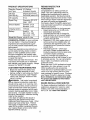 6
6
-
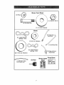 7
7
-
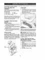 8
8
-
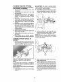 9
9
-
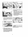 10
10
-
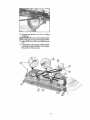 11
11
-
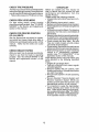 12
12
-
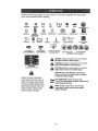 13
13
-
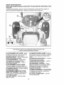 14
14
-
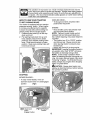 15
15
-
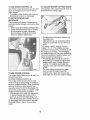 16
16
-
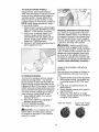 17
17
-
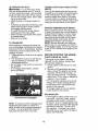 18
18
-
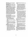 19
19
-
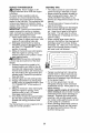 20
20
-
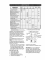 21
21
-
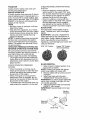 22
22
-
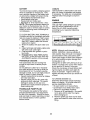 23
23
-
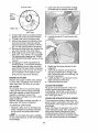 24
24
-
 25
25
-
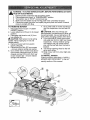 26
26
-
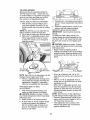 27
27
-
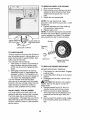 28
28
-
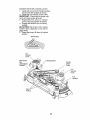 29
29
-
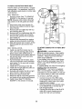 30
30
-
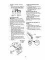 31
31
-
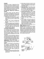 32
32
-
 33
33
-
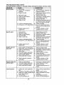 34
34
-
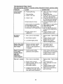 35
35
-
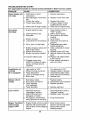 36
36
-
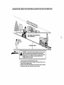 37
37
-
 38
38
-
 39
39
-
 40
40
-
 41
41
-
 42
42
-
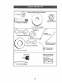 43
43
-
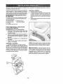 44
44
-
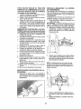 45
45
-
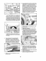 46
46
-
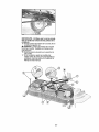 47
47
-
 48
48
-
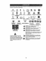 49
49
-
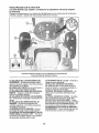 50
50
-
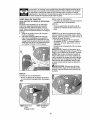 51
51
-
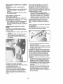 52
52
-
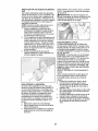 53
53
-
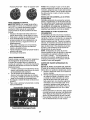 54
54
-
 55
55
-
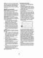 56
56
-
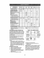 57
57
-
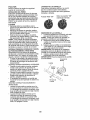 58
58
-
 59
59
-
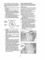 60
60
-
 61
61
-
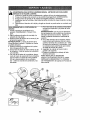 62
62
-
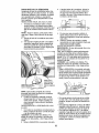 63
63
-
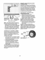 64
64
-
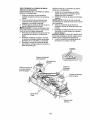 65
65
-
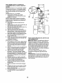 66
66
-
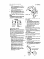 67
67
-
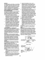 68
68
-
 69
69
-
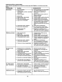 70
70
-
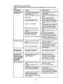 71
71
-
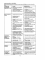 72
72
-
 73
73
-
 74
74
-
 75
75
-
 76
76


Craftsman 917286460 El manual del propietario
- Categoría
- Cortadoras de césped
- Tipo
- El manual del propietario
En otros idiomas
- English: Craftsman 917286460 Owner's manual