Music Laboratory System Installation Guide 27
11. Troubleshooting
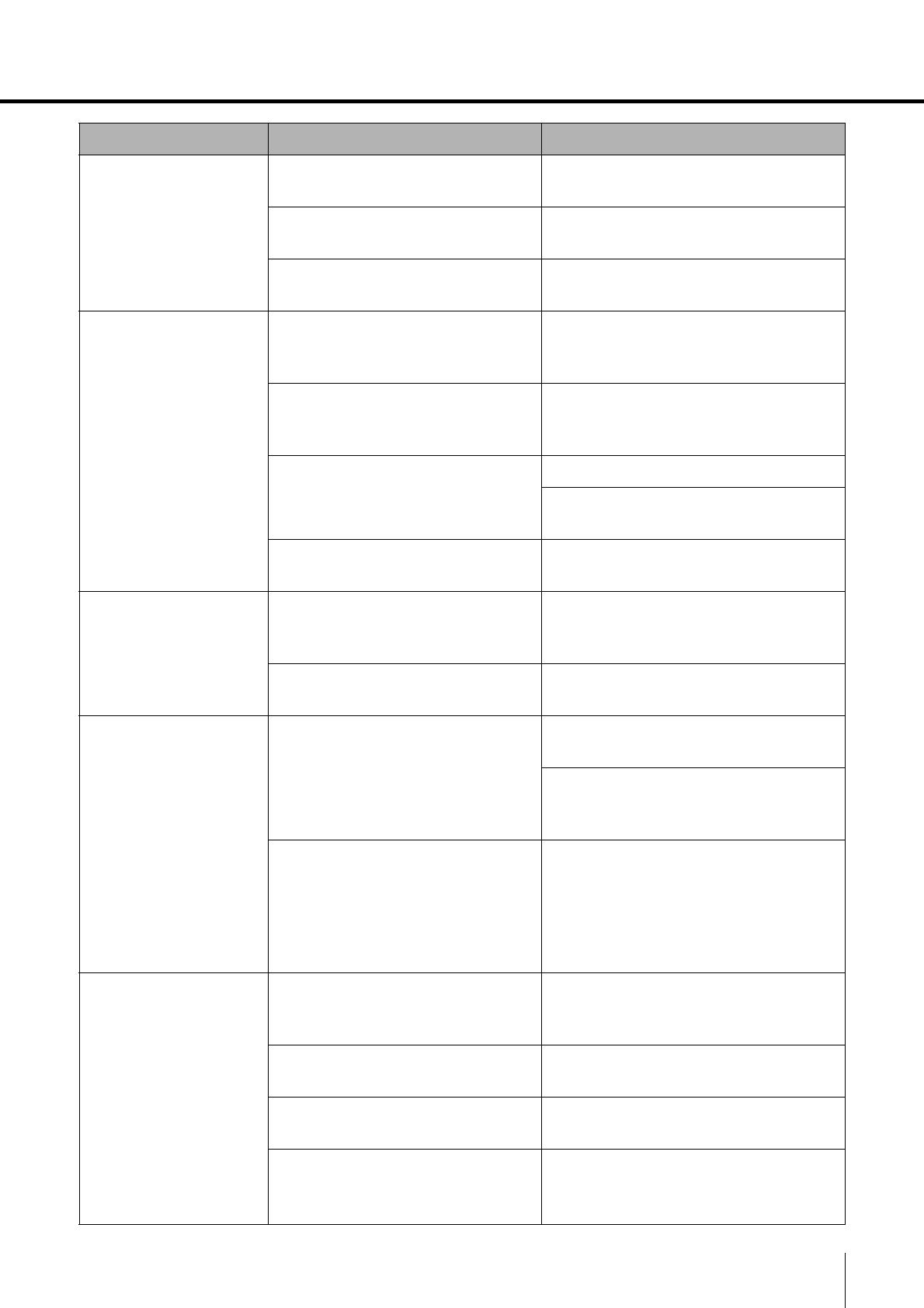
Symptom Cause Remedy
A device does not
turn on.
• The Ethernet cable is
disconnected.
Disconnect, and then reconnect.
• PoE power is not supplied by
the network switch.
Make sure that a PoE powered
Ethernet switch is used.
• The PoE power supplied by the
network switch is insufficient.
Check the power supply specifications
of the Ethernet switch.
No sound is output./
Minimal sound is
output.
• The [MASTER VOL.] knob or
[MY VOL.] knob is incorrectly
adjusted.
Make sure that both knobs are turned
to the 12 o’clock position.
• The master volume of
instrument settings are
incorrect.
Adjust the master volume of
instrument.
• Headphones are incorrectly
connected.
Disconnect, and then reconnect.
Change to a microphone headset
compatible with the CTIA standard.
• The [INPUT GAIN] switch is
incorrectly set.
Make sure that it is set to “+10 dB”.
A humming sound
can be heard.
• The power supply for the
Ethernet switch is not grounded.
Make sure that the Ethernet switch is
grounded. Connect to a 3-pin electrical
outlet.
• An STP cable is not being used.
Change the Ethernet cable to an STP
cable.
The sound from the
microphone is not
transmitted to the
other party.
A microphone headset that is not
compatible with the CTIA standard
is being used.
Change to a microphone headset
compatible with the CTIA standard.
A conversion cable that converts from
the OMTP standard to the CTIA
standard is being used.
The microphone headset is
connected to the [DUO] jack.
Connect the microphone headset to
the [MAIN] jack. A microphone
headset connected to the [DUO] jack
operates only when a microphone
headset is also connected to the
[MAIN] jack (DUO mode).
Cannot communicate
with ML Touch.
• The wireless access point and
iPad are not connected.
Check the Wi-Fi settings for the iPad,
and then correctly select the specified
wireless access point.
• The DIP switch settings on the
MLA-200 are incorrect.
Check that the ID specified with the
DIP switch is the intended ID.
• The ID of the MRX7-D is
incorrectly specified.
Check that it is the intended ID.
• The network address is
incorrectly specified.
Check the DHCP server settings.
Specify according to the table in step
2-3.


