GE JVX5300BJTS Guía de instalación
- Categoría
- Campanas de cocina
- Tipo
- Guía de instalación
Este manual también es adecuado para

Write the model and serial
numbers here:
Model # _________________
Serial # _________________
You can find them on a label
on the inside of the hood.
ESPAÑOL
Para consultar una version en
español de este manual de
instrucciones, visite nuestro sitio de
internet GEAppliances.com.
RANGE HOODS
49-80783-4 05-17 GEA
SAFETY INFORMATION ...........3
USING THE HOOD
Controls ................................5
Chef Connect ...........................6
CARE AND CLEANING
Filters ..................................7
Surfaces ................................8
Lights ..................................8
INSTALLATION INSTRUCTIONS ..9
TROUBLESHOOTING TIPS ........ 21
WARRANTY ........................22
ACCESSORIES .....................23
CONSUMER SUPPORT ............24
JVX3240
JVX3300
JVX5300
JVX5360
JVX5305
JVX5365
PVX7300
PVX7360
OWNER’S MANUAL &
INSTALLATION
INSTRUCTIONS
GE is a trademark of the General Electric Company. Manufactured under trademark license.
991.0480.237

2 49-80783-4
THANK YOU FOR MAKING GE APPLIANCES A PART OF YOUR HOME.
Whether you grew up with GE Appliances, or this is your first, we’re happy to have you in the family.
We take pride in the craftsmanship, innovation and design that goes into every GE Appliances
product, and we think you will too. Among other things, registration of your appliance ensures that we
can deliver important product information and warranty details when you need them.
Register your GE appliance now online. Helpful websites and phone numbers are available in the
Consumer Support section of this Owner’s Manual. You may also mail in the pre-printed registration
card included in the packing material.

49-80783-4 3
SAFETY INFORMATION
IMPORTANT SAFETY INFORMATION
READ ALL INSTRUCTIONS BEFORE USING
READ AND SAVE THESE INSTRUCTIONS
WARNING
TO REDUCE THE RISK OF FIRE,
ELECTRIC SHOCK OR INJURY TO PERSONS,
OBSERVE THE FOLLOWING:
A. Use this unit only in the manner intended by the
manufacturer. If you have questions, contact the
manufacturer.
B. Before servicing or cleaning unit, switch power off
at service panel and lock the service disconnecting
means to prevent power from being switched
on accidentally. When the service disconnecting
means cannot be locked, securely fasten a
prominent warning device, such as a tag, to the
service panel.
C. Do not use this unit with any solid-state speed
control device.
D. This unit must be grounded.
WARNING
TO REDUCE THE RISK OF A
RANGE TOP GREASE FIRE:
A. Never leave surface units unattended at high
settings. Boilovers cause smoking and greasy
spillovers that may ignite. Heat oils slowly on
medium settings.
B. Always turn hood ON when cooking at high heat or
when flambéing food (i.e. Crepes Suzette, Cherries
Jubilee, Peppercorn Beef Flanbé).
C. Clean ventilating fans frequently. Grease should not
be allowed to accumulate on fan or filter.
D. Use proper pan size. Always use cookware
appropriate for the size of the surface element.
WARNING
TO REDUCE THE RISK OF INJURY
TO PERSONS IN THE EVENT OF A RANGE TOP
GREASE FIRE, OBSERVE THE FOLLOWING*:
A. SMOTHER FLAMES with a close-fitting lid, cookie
sheet or metal tray, then turn off the burner. BE
CAREFUL TO PREVENT BURNS. If the flames do
not go out immediately, EVACUATE AND CALL
THE FIRE DEPARTMENT.
B. NEVER PICK UP A FLAMING PAN—You may be
burned.
C. DO NOT USE WATER, including wet dishcloths or
towels—a violent steam explosion will result.
D. Use an extinguisher ONLY if:
1. You know you have a Class ABC extinguisher,
and you already know how to operate it.
2. The fire is small and contained in the area where
it started.
3. The fire department is being called.
4. You can fight the fire with your back to an exit.
* Based on “Kitchen Fire Safety” published by NFPA.
CAUTION
FOR GENERAL VENTILATING USE
ONLY. DO NOT USE TO EXHAUST HAZARDOUS
OR EXPLOSIVE MATERIALS AND VAPORS.

4 49-80783-4
SAFETY INFORMATION
IMPORTANT SAFETY INFORMATION
READ ALL INSTRUCTIONS BEFORE USING
How to Remove Protective Shipping Film and Packaging Tape
Carefully grasp a corner of the protective shipping film
with your fingers and slowly peel it from the appliance
surface. Do not use any sharp items to remove the film.
Remove all of the film before using the appliance for the
first time.
To assure no damage is done to the finish of the
product, the safest way to remove the adhesive from
packaging tape on new appliances is an application of
a household liquid dishwashing detergent. Apply with a
soft cloth and allow to soak.
NOTE: The adhesive must be removed from all parts.
READ AND SAVE THESE INSTRUCTIONS
REMOTE ENABLE EQUIPMENT (on some models)
This device complies with part 15 of the FCC Rules.
Operation is subject to the following two conditions: (1)
This device may not cause harmful interference, and
(2) this device must accept any interference received,
including interference that may cause undesired
operation.
The wireless communication equipment installed on
this hood has been tested and found to comply with
the limits for a Class B digital device, pursuant to part
15 of the FCC Rules. These limits are designed to:
(a) provide reasonable protection against harmful
interference in a residential installation. This
equipment generates, uses, and can radiate radio
frequency energy and, if not installed and used in
accordance with the instructions, may cause harmful
interference to radio communications. However, there
is no guarantee that interference will not occur in a
particular installation. If this equipment does cause
harmful interference to radio or television reception,
which can be determined by turning the equipment off
and on, the user is encouraged to try to correct the
interference by one or more of the following measures:
Ŷ5HRULHQWRUUHORFDWHWKHUHFHLYLQJDQWHQQD
Ŷ,QFUHDVHWKHVHSDUDWLRQEHWZHHQWKHHTXLSPHQWDQG
receiver.
Ŷ&RQQHFWWKHHTXLSPHQWLQWRDQRXWOHWRQDFLUFXLW
different from that to which the receiver is
connected.
Ŷ&RQVXOWWKHGHDOHURUDQH[SHULHQFHGUDGLR79
technician for help.
(b) accept any interference received, including
interference that may cause undesired operation of the
device.
Note that any changes or modifications to the wireless
communication device installed on this oven that are
not expressly approved by the manufacturer could void
the user’s authority to operate the equipment.

49-80783-4 5
1. Rangehood Control Panel: The control panel
is located on the front of the canopy.
2. Light Button: 2Q1LJKW2IIVZLWFKIRUWKHOLJKWV
Press the LIGHT button to turn the lights on, again
to set the lights to night setting, and again to turn off.
3. Fan Off Button: Off switch for the fan. The fan
can be operated by pressing any of the fan setting
buttons. Hold for 3 seconds to activate auto off after
15 minutes.
4. Fan Settings Buttons: Speed control for
fan. Press the button Lo for LOW speed, Med for
MEDIUM speed and Hi for HIGH speed. Hold down
the Hi button for 3 seconds to activate the BOOST
SPEED that will run for 10 minutes.
4
1
23
On Some Models
On Some Models
1. Rangehood Control Panel: The control panel
is located on the front of the canopy.
2. Light Switch: Light switch toggles between
On and Off.
3. Fan Power Switch: The power switch toggles
between fan settings Hi, Lo, and Off.
Controls
USING THE HOOD: Controls
Light Fan
On
Off
Hi
Lo
Off
1
23

6 49-80783-4
1. Rangehood Control Panel: The glass touch
control panel is located on the front of the canopy.
2. Light Pad: 2Q1LJKW2IIVZLWFKIRUWKHOLJKWV
Press the LIGHT pad to turn the lights on, again to
set the lights to night setting, and again to turn off.
3. Auto Off Pad: Off switch for the fan. The fan
can be operated by pressing any of the fan setting
pads. Hold for 3 seconds to activate auto off after
15 minutes.
4. Fan Settings Pads: Speed control for fan.
Press the pad Lo for LOW speed, Med for MEDIUM
speed and Hi for HIGH speed. Hold down the Hi
button for 3 seconds to activate the BOOST SPEED
that will run for 10 minutes.
5. Chef Connect: This is a Bluetooth
®
pairing
feature for use with other compatible Chef Connect
enabled products on a cooktop or a range. When
the device is paired, the light and fan will turn
ON at the Default Sync Settings upon receiving a
command from the range or cooktop. It will remain
ON at that setting until the user changes it.
On Some Models
4
1
32
Controls
Chef Connect
USING THE HOOD: &RQWUROV&KHI&RQQHFW
5
Chef Connect Operation Bluetooth
®
Connection
To pair with another device:
To start the pairing process on the hood, press and hold
the Light pad for 3 seconds. The backlight for the Lo –
Med – Hi – Light will flash in that sequence until the hood
is paired with the range or other device. If the pairing is
successful, all 4 lights (Lo, Med, Hi, and Light) will flash
three times simultaneously and then turn off.
It will time out after 2 minutes if pairing is not completed.
After which the pairing sequence will need to be restarted.
To cancel pairing:
To cancel the pairing hold the Light pad for 3 seconds
and then turn off the hood.
Default Sync Settings:
The factory default setting for the light will be the
brightest.
The factory default setting for the fan sync will be OFF.
The user can change the Default Sync Settings by
pressing and holding the Lo pad for 3 seconds. This will
enter the Default Settings Mode. Once in this mode, the
backlights for all buttons (Lo, Med, Hi, and Light) will
EOLQN2Q2IILQGHILQLWHO\DQGWKHIDQDQGOLJKWZLOOVZLWFK
to the current Default Sync Setting, so the user knows
what the current default value is. At this time, set the light
and fan to the desired default levels. Once the user is
satisfied with the selection, press and hold the Off pad
for 3 seconds. This will exit this mode. At that time the
backlights will stop blinking and the state of the fan and
light will change back to their prior state before entering
the Default Settings Mode.

49-80783-4 7
Be sure the circuit breaker is off and all surfaces are cool before cleaning or servicing any part of the vent hood.
Metal Grease Filter
The metal filters trap grease during cooking.
The filter must ALWAYS be in place when the hood is in
use. The grease filter is dishwasher-safe and should be
cleaned every 6 months, or as needed.
To remove:
Pull downward on the filter lock to release the filter.
To replace:
Fit the tabs at the bottom of the filter into the slots in the
back of the filter opening. Lift up the front side of the filter
and push gently until the filter locks into place. Make sure
the filter lock is in the closed position to secure the filter.
To clean, swish the filter in hot soapy water and rinse
in clean water or wash it in the dishwasher. Do not use
abrasive cleansers.
NOTE: Some discoloration may occur in the dishwasher.
Charcoal Filter (for recirculation installation only)
If the model is not vented to the outside, the air needs to
be recirculated through a disposable charcoal filter that
helps remove smoke and odors.
NOTE: DO NOT rinse, or put charcoal filter in an
automatic dishwasher.
The charcoal filter cannot be cleaned. It must be
replaced. It is recommended that the charcoal filter
be replaced every 6-12 months or if it is noticeably
dirty or discolored.
To inquire about purchasing replacement charcoal filters
or to find the location of a dealer nearest you, please
visit GEApplianceParts.com
To install (on some models):
1. Remove the metal filters—see Metal Grease Filter
section.
2. Place the side of the charcoal filter with the tabs
against the bottom of the blower.
3. Drive screws in the 2 locations shown in the picture.
4. Replace the metal filters—see Metal Grease Filter
section.
To remove:
1. Remove the metal filters—see Metal Grease Filter
section.
2. Remove the 2 screws holding the charcoal filter in
place to remove.
Filters
CARE AND CLEANING: Filters
NOTE: For this
configuration one grease
filter is only used in the
vented mode.
Charcoal filter included on models:
JVX3240 and JVX3300
Charcoal filter not included on this model.
Visit GEAppliances.com to order.
NOTE: For this
configuration charcoal
filter is installed in
place of grease filter.

8 49-80783-4
Lights
Stainless Steel Surfaces (on some models)
Do not use a steel wool pad; it will scratch the
surface.
To clean the stainless steel surface, use warm sudsy
water or a stainless steel cleaner or polish. Always wipe
the surface in the direction of the brush line. Follow
the cleaner instructions for cleaning the stainless steel
surface. Cleaners with oxalic acid such as Bar Keepers
Friend Soft Cleanser™ will
remove surface rust, tarnish, and
small blemishes. To receive a
$2.00 coupon for a trial sample
of Bar Keepers Friend Soft
Cleanser™ follow the link below
or scan the QR Code.
www.barkeepersfriend.com/ge
Use only a liquid cleanser free of grit and rub in the
direction of the brush lines with a damp soft sponge.
To inquire about purchasing stainless steel appliance
cleaner or polish, or to find the location of a dealer
nearest you, please visit GEApplianceParts.com
Painted Surfaces (on some models)
Do not use a steel wool pads or other abrasive
cleaners; they will scratch the surface.
Clean grease-laden surfaces of the hood frequently. To
clean the hood surface, use a hot, damp cloth with a
mild detergent suitable for painted surfaces. About one
tablespoon of ammonia may be added to the water. Use
a clean, hot, damp cloth to remove soap. Dry with a dry,
clean cloth.
NOTE: When cleaning, take care not to come in contact
with filters and other surfaces.
CAUTION
When cleaning the hood surfaces,
be certain that you do not touch the light with moist
hands or cloth. A warm or hot light may break if
touched with a moist surface. Always let the light
cool completely before cleaning around it.
CAUTION
Allow lights to cool before touching.
On Some Models
1. Before attempting to replace the lights, make sure that
the light switch is turned off.
2. Remove light cover.
3. Unscrew light counterclockwise to unlock light and
pull out.
4. Replace with new light of same type (standard
incandescent), making sure socket is properly inserted
into the housing of the lamp holder.
On Some Models
1. Before attempting to replace the lights, make sure that
the light switch is turned off.
2. Rotate light counterclockwise to unlock and pull out.
Wearing latex gloves may offer a better grip.
3. Replace with new light of same type, making sure
pins are inserted properly into the sockets of the lamp
holder and turn clockwise to lock.
All lamps need to be GU10 compatible.
Surfaces
CARE AND CLEANING:6XUIDFHV/LJKWV
Light Cover
Rotate the lamp until the
pins are located in narrow
neck of the socket.
Lamp
Holder
Sockets

49-80783-4 9
Installation
Instructions
INSTALLATION INSTRUCTIONS
BEFORE YOU BEGIN
Read these instructions completely and
carefully.
•
IMPORTANT — Save these
instructions for local inspector’s use.
•
IMPORTANT — Observe all governing
codes and ordinances.
• Note to Installer – Be sure to leave these
instructions with the Consumer.
• Note to Consumer – Keep these instructions for
future reference.
• Skill level – Installation of this vent hood requires
basic mechanical and electrical skills.
• Proper installation is the responsibility of the
installer.
• Product failure due to improper installation is not
covered under the Warranty.
FOR YOUR SAFETY
WARNING
Before beginning the installation,
switch power off at service panel and lock the
service disconnecting means to prevent power from
being switched on accidentally. When the service
disconnecting means cannot be locked, securely
fasten a prominent warning device, such as a tag,
to the service panel.
CAUTION
To reduce risk of fire and to
properly exhaust air, be sure to duct air outside.
Do not vent exhaust air into spaces within walls or
ceilings or into attics, crawl spaces or garages.
WARNING
Disconnect all electrical power
at the main circuit breaker or fuse box before
installing.
Under the Cabinet (UTC) Hoods
JVX3240, JVX3300, JVX5300, JVX5360, JVX5305,
JVX5365, PVX7300, PVX7360
WARNING
TO REDUCE THE RISK OF FIRE,
ELECTRIC SHOCK OR INJURY TO PERSONS,
OBSERVE THE FOLLOWING:
A. Installation work and electrical wiring must be
done by qualified person(s) in accordance with
all applicable codes and standards, including
fire-rated construction.
B. Sufficient air is needed for proper combustion
and exhausting of gases through the flue
(chimney) of fuel burning equipment to prevent
back drafting. Follow the heating equipment
manufacturer’s guidelines and safety standards
such as those published by the National Fire
Protection Association (NFPA), the American
Society for Heating, Refrigeration and Air
Conditioning Engineers (ASHRAE) and the local
code authorities.
C. When cutting or drilling into wall or ceiling, do
not damage electrical wiring and other hidden
utilities.
D. Ducted fans must always be vented to the
outdoors.
WARNING
TO REDUCE THE RISK OF FIRE,
USE ONLY METAL DUCT WORK.
“If you have questions, call GE Appliances at 800.GE.CARES (800.432.2737)
or visit our website at: GEAppliances.com”

10 49-80783-4
DUCTWORK REQUIREMENTS
WARNING
TO REDUCE THE RISK OF FIRE, USE ONLY METAL DUCTWORK.
NOTE: Read the ductwork sections only if you do not have existing ductwork. If you have existing ductwork, skip
to the “Damage” section and proceed.
The venting system must exhaust to the outside.
This hood can be vented vertically through upper cabinets or horizontally through an outside wall. Ductwork is
not included.
Exhaust connection
This hood is designed to be vented vertically using a 7" round duct or a 3
1
»4” x 10” rectangular duct or
horizontally using a 3
1
»4” x 10” rectangular duct.
Duct length
The ducting from this fan to the outside of the building has a strong effect on the air flow, noise and energy use
of the fan. Use the shortest, straightest duct routing possible for best performance, and avoid installing the fan
with smaller ducts than recommended. Insulation around the ducts can reduce energy loss and inhibit mold
growth. Fans installed with existing ducts may not achieve their rated air flow.
NOTE: For an ENERGY STAR
®
model, unit must be vented mode to be considered ENERGY STAR
®
certified.
Also, for these models do not use less than 7” diameter duct.
INSTALLATION PREPARATION
Installation Preparation
INSULATION AND/OR CAULK AROUND THE DUCTS
Cabinet
Hood
Add Insulation
DQGRU&DXON
Add tape to joint
Add Insulation
DQGRU&DXON
Roof Cap
Round or Rectangular Duct
Wall Cap

49-80783-4 11
Installation Preparation
MOUNTING SPACE
PRODUCT DIMENSIONS
NOTES:
• Hood width may be greater than the width of the
range or cooktop, but it may not be smaller.
• Installation height should be measured from the
cooking surface to the lowest part of the hood.
This hood must be installed onto a cabinet. It can
be vented to the outdoors, or it can be installed for
recirculating operation.
Bottom edge
of cabinet
needs to
be 30” or
more from
the cooking
surface
24" Min required
30" Max recommended
to the bottom of
the hood
34"-36"
Typical
ƎƎRUƎ to
match cooktop width
INSTALLATION PREPARATION
*Controls may vary
Top View
Back View
X20”
5”7
1
»2”
ø 7”
4”
3
1
»4”
1
»2”
3
»4”
5
1
»2”
12”
Size X
24” 23
15
»16”
30” 29
15
»16”
36” 35
15
»16”
5”7
1
»2”
3
1
»4”
3
»4”
3
»4”

12 49-80783-4
INSTALLATION PREPARATION
REMOVE THE PACKAGING
CAUTION
Wear gloves to protect against
sharp edges.
• Remove the hardware bag, literature package and
other boxed parts.
• Remove and properly discard the protective plastic
wrapping and other packaging materials.
TOOLS AND MATERIALS
REQUIRED (NOT SUPPLIED)
:LUHFXWWHUVWULSSHU
Spirit level
Aluminized
Duct tape
Torx 10, 15, 20 driver
Charcoal Filter (required for some
models in recirculation mode)
Safety glasses
Strain relief for
junction box
Electric drill, #2 Phillips,
flat head, and
9
»32" drill bit
UL listed wire nuts
Pencil and tape measure
PLAN THE INSTALLATION
CAUTION
To reduce risk of fire and to
properly exhaust air, be sure to duct the air outside
– Do not vent exhaust air into spaces within walls or
ceilings or into attics, crawl spaces, or garages.
PARTS SUPPLIED FOR
INSTALLATION
• 1 Hardware Package
• 1 Literature Package
• 1 Vented Mode Deflector Part
PARTS NEEDED FOR INSTALLATION
• 1 Strain Relief
• Power Supply Cable
• 1 Wall or Roof Cap (for external venting only)
• All Metal Ductwork (for external venting only)
NOTE: This range hood can be installed as either
ducted or recirculation. In a ducted application,
this range hood can be vented through the wall or
ceiling. When installed for recirculation, the range
hood vents out the front of the hood.
NOTE: Before making any cuts or holes for
installation, determine which venting method will be
used and carefully calculate all measurements.
Installation Preparation

49-80783-4 13
INSTALLATION PREPARATION
Installation Preparation
INSTALLATION DIMENSIONS
RANGE HOOD COMPONENTS
A. Hood Body
B. 'DPSHU'XFW&RQQHFWRU
C. Mounting Bracket
D. Screws (4)
E. Screws (4)
F. Screws (6)
HARDWARE COMPONENTS
The hood is designed to fit 12" deep cabinets. For
15" deep cabinets, filler panel kits are available from
GEApplianceParts.com:
JXS50SS for 30" wide hoods
JXS56SS for 36" wide hoods
DE F
C
C
B
A
D
D
E
F
E
12"
X
X = Distance from hood to cooktop
(varies depending on installation)
Required Min. = 24"
Recommended Max. = 30"
34"-36"
Typical
F
For vented
mode only

14 49-80783-4
INSTALLATION PREPARATION
Installation Preparation
POWER SUPPLY
IMPORTANT – (Please read carefully)
WARNING
FOR PERSONAL SAFETY, THIS APPLIANCE
MUST BE PROPERLY GROUNDED.
Remove house fuse or open circuit breaker before
beginning installation.
Do not use an extension cord or adapter plug with
this appliance. Follow National Electrical Codes or
prevailing local codes and ordinances.
Electrical supply
These vent hoods must be supplied with 120V,
60Hz, and connected to an individual, properly
grounded branch circuit, and protected by a 15 or
20 amp circuit breaker or time delay fuse.
• Wiring must be 2 wire with ground.
• If the electrical supply does not meet the above
requirements, call a licensed electrician before
proceeding.
• Route house wiring as close to the installation
location as possible in the ceiling or wall.
• Connect the wiring to the house wiring in
accordance with local codes.
Grounding instructions
The grounding conductor must be connected to
a ground metal, permanent wiring system, or an
equipment-grounding terminal or lead on the hood.
WARNING
The improper connection of the
equipment-grounding conductor can result in a risk
of electric shock. Check with a qualified electrician
or service representative if you are in doubt
whether the appliance is properly grounded.
ADVANCE PLANNING
Vented Install Planning
• This hood is designed to be vented vertically using
a 7" round duct or a 3
1
»4" x 10" rectangular duct or
horizontally using a 3
1
»4" x 10" rectangular duct.
• Use metal ductwork only.
• Determine the exact location of the vent hood.
• Plan the route for venting exhaust to the outdoors.
To maximize the ventilation performance of the
vent system:
1. Minimize the duct run length and number of
transitions and elbows.
2. Maintain a constant duct size.
3. Seal all joints with duct tape to prevent any
leaks.
4. Do not use any type of flexible ducting.
• Install a wall cap or roof cap at the exterior
opening. Purchase the wall or roof cap and any
transition and length of duct needed in advance.
• When applicable, install any makeup (replacement)
air system in accordance with local building
code requirements. Visit GEAppliances.com for
available makeup air solutions.
Recirculation Install Planning
This hood may be installed in recirculation mode
and is shipped in this configuration. The charcoal
filter is necessary for recirculation installation.
This part may need to be ordered separately
depending on model.
Power Supply Planning
The location of the power supply connection is
called out in the Prepare for Electrical and Venting
section on page 15.

49-80783-4 15
1
SELECT VENT OPTION THAT
YOUR INSTALLATION WILL
REQUIRE (A-D)
A
Outside top exhaust
(Vertical duct—3
1
»4” x 10” Rectangular)
B
Outside top exhaust
(Vertical duct—7” Round)
C
Outside rear exhaust
(Horizontal duct—3
1
»4” x 10”
Rectangular)
D
Recirculating
(Unit is configured from factory in
this mode)
2
PREPARING MOUNTING
For cabinets with dimensions below, the
mounting bracket may be used for any model.
Otherwise, the hood must mount directly
to bottom of cabinet. Wood shims may be
needed for cabinets with a recessed bottom.
Skip to step B.
A
To install the mounting bracket
Drive (E) screws in partway into mounting
bracket. The bracket labeled "R" will be
used on the right side of the cabinet and the
bracket labeled "L" will be used on the left
side of the cabinet.
Under the cabinet that you are placing the
range hood, attach the mounting bracket as
shown below with (F) screws. Make sure
orientation is correct. Brackets should be
located against the back wall and flush with
the bottom of the cabinet.
NOTE: Repeat on left side.
INSTALLATION PREPARATION
Installation Preparation
X
3
»4" Depth
Push
against
wall
Flush
with
cabinet
Cabinet X
24” 22
1
»2”
30” 28
1
»2”
36” 34
1
»2”
E

16 49-80783-4
2
PREPARING MOUNTING (Cont)
B
To install to the bottom of cabinet
Use the diagram or hood as a template and
mark the locations on the cabinet for the
keyholes screws.
Drive the 4 (F) screws partway into the bottom
of the cabinet (or wood shims).
INSTALLATION PREPARATION
Installation Preparation
3
PREPARE FOR ELECTRICAL
AND VENTING
Select the vent option that your installation will
require and proceed to that section:
A
Outside top exhaust
(Vertical duct–3
1
»4” x 10” Rectangular)
• Use the diagram as a template and mark the
locations on the cabinet for ductwork and
electrical wiring.
B
Outside top exhaust
(Vertical duct–7” Round)
• Use the diagram as a template and mark the
locations on the cabinet for ductwork and
electrical wiring.
C
Outside rear exhaust
(Horizontal duct–3
1
»4” x 10” Rectangular)
• Use the diagram as a template and mark the
locations on the cabinet for ductwork and
electrical wiring.
Center line
Electrical access
hole (in cabinet
bottom)
Cabinet front
Cabinet Bottom
Vertical duct
access hole
5
1
»4” 5
1
»4”
7
1
»2”
ø1
1
»4”
4”
1
»2”
3
»4”
Center line
Electrical access
hole (in cabinet
bottom)
Cabinet front
Cabinet Bottom
7
1
»2”
ø1
1
»4”
3
»4”
Access
hole for 7”
round duct
8” DIA.
HOLE
4
1
»4”
Center line
Electrical access
hole (in wall)
Cabinet Front
Cabinet
Bottom
7
1
»2”
ø1
1
»4”
3
»4”
5
1
»4” 5
1
»4”
3
»4”
4
1
»4”
Wood shims
(recessed-bottom
cabinets only)
Center
line
Cabinet Bottom
Cabinet front
2
1
»2”
10
1
»4”
X
Hood mounting screws (4)
Cabinet X
24” 10
3
»4”
30” 13
3
»4”
36” 16
3
»4”

49-80783-4 17
4
REMOVE ELECTRICAL
KNOCKOUTS
Use a flat blade screwdriver, remove the
appropriate electrical knockout from the back or
the top of the hood.
5
REMOVE JUNCTION BOX
Remove junction box from inside the hood. Set
the junction box and mounting screws aside.
6
REMOVE DUCT KNOCKOUT(S)
FOR VENTED INSTALLATION
Determine which ducting option to use.
Using a flat blade screwdriver, remove the
appropriate duct knockout(s) from the top or
back of the hood.
NOTE: If the hood is to be installed in a
recirculation, non-vented ductless manner, do not
remove any venting knockouts.
NOTE: For an ENERGY STAR
®
model, unit must
be vented mode to be considered ENERGY STAR
®
certified.
7
ATTACH
DAMPER/DUCT CONNECTOR
Attach damper/duct connector over knockout
opening with two or four (D) screws. Make sure
damper pivot is nearest to top/back edge of
hood. Remove any packaging tape to allow
damper to move freely.
INSTALLATION PREPARATION
Installation Preparation
3
1
»4” x 10” Rectangular
vertical discharge. Remove top
rectangular duct knockout only.
7” Round vertical discharge.
Remove semi-circular duct
knockout and top rectangular
duct knockout.
3
1
»4” x 10” Rectangular horizontal
discharge. Remove rear rectangular
duct knockout only.
Rectangular Ducting
Round Ducting
Damper (vertical discharge
position shown)
7RSEDFN
edge
Tape
7” round
exhaust
adaptor
Junction Box
Screws

18 49-80783-4
INSTALLATION PREPARATION
Installation Instructions
On Some Models:
Remove, rotate, and re-install deflector part for
vented mode.
Existing deflector part (on some models)
8
FOR VENTED INSTALLATIONS
On Some Models:
Install with vented mode deflector part.
On Some Models:
The existing deflector part must be removed.
To remove the existing deflector piece, unscrew
to remove it. Install the vented mode deflector
part included in hardware kit using the screw.
The deflector must be installed to prevent
leakage in case of vented installation.
Vented mode deflector part
(on some models)
Existing deflector part
(on some models)

49-80783-4 19
10
MOUNT THE UTC
Place the hood onto the partially installed
screws using the keyholes and slide the hood
back into position.
9
FEED IN WIRES
Lift the hood into position and feed the house
wiring through the wiring knockout.
1
2
11
SECURE HOOD
Tighten the mounting screws. Be sure the
screw heads are in the narrow neck of the
keyhole slot.
Keyhole (4)
Mounting
screw (4)
12
CONNECT DUCTWORK TO HOOD
(Ducted installations only)
Connect ducting to hood. Use duct tape to
make joints secure and airtight.
INSTALLATION INSTRUCTIONS
Installation Instructions
13
ELECTRICAL CONNECTION
1. Connect the Power Supply Cable to the range
hood. Attach the white lead of the power
supply to the white lead of the range hood
(A) with a wire nut (C). Attach the black lead
of the power supply to the black lead of the
range hood (B) with a wire nut (C). Connect
the green (D) ground wire under the green
grounding screw.
2. Replace the junction box cover.
B
D
C
A

20 49-80783-4
INSTALLATION INSTRUCTIONS
Installation Instructions
14
FINISH THE INSTALLATION
On Some Models:
1. For recirculation: Install the charcoal filter.
2. For ducted installation: Install the grease
filters.
On Some Models:
1. For recirculation: Place the charcoal filter
(not included) in place and mount using 2
screws. Replace the grease filters.
2. For vented installation: Install the grease
filters.

49-80783-4 21
Troubleshooting tips ... Before you call for service
TROUBLESHOOTING TIPS
Save time and money! Review the charts on the following pages first and you may not need to call for service.
Problem Possible Cause What To Do
Fan/Light does not operate
when either button is
pressed
A house fuse may be blown or
a circuit breaker tripped.
Replace fuse or reset circuit breaker.
Fan does not operate when
fan Lo, Med, Hi buttons are
pressed
The blower connector is loose
or not plugged into its mating
connector.
Disconnect power to the unit. Remove the filters and
look up at the blower. If the blower connector plug is
loose or you see the connector dangling, the installer
failed to plug it in securely. See the mini manual for the
plug location and how to plug in the connector.
Loud or abnormal airflow
noise
Wrong duct size used in
installation.
Using smaller duct pipe will cause reduced venting.
Minimize the duct run length and number of transitions
and elbows. GE service technicians cannot correct this
issue if installed improperly.
Fan fails to circulate
air or moves air slower
than normal and/or fan is
making loud or abnormal
airflow noise
Obstructions in duct work. Make sure nothing is blocking the vent. Make sure your
wall or roof cap has a blade or door.
Damper blade on wall or roof
cap may not be open.
Make sure damper swings freely. Damper blades may
flip over and will not fully open when this happens.
Adjust to original position.
Metal grease filter and charcoal
filter (if present) may be dirty.
Clean the metal grease filter and replace charcoal filter
(if present). See Care and Cleaning of the Vent Hood.
Insufficient makeup
(replacement) air
Sufficient makeup (replacement) air is required for
exhausting appliances to operate to rating. Check with
local building codes, which may require or strongly
advise the use of makeup air. Visit GEAppliances.com
for available makeup air solutions.
The hood controls are not
operating correctly
Control logic confused. Disconnect power to the hood by resetting the circuit
breaker. Wait 30 seconds to allow controls to reset.
Early light failure Light wattage is too high. Replace with correct wattage.
Fan continually cycles off
and on
The motor is probably
overheating and turning
itself off. This can be harmful
to the motor. Filter may be
excessively soiled.
Clean the metal grease filter and replace charcoal filter
(if present). See Care and Cleaning of the Vent Hood.

22 49-80783-4
Staple your receipt here. Proof of the original purchase
date is needed to obtain service under the warranty.
GEAppliances.com
All warranty service is provided by our Factory Service Centers, or an authorized Customer Care
®
technician. To schedule
service online, visit us at www.geappliances.com/service_and_support/, or call GE Appliances at 800.GE.CARES
(800.432.2737). Please have your serial number and your model number available when calling for service.
Servicing your appliance may require the use of the onboard data port for diagnostics. This gives a GE Appliances factory
service technician the ability to quickly diagnose any issues with your appliance and helps GE Appliances improve its
products by providing GE Appliances with information on your appliance. If you do not want your appliance data to be
sent to GE Appliances, please advise your technician not to submit the data to GE Appliances at the time of service.
What GE Appliances will not cover:
Ŷ Service trips to your home to teach you how to use
the product.
Ŷ Improper installation, delivery, or maintenance.
Ŷ Failure of the product if it is abused, misused,
modified, or used for other than the intended purpose
or used commercially.
Ŷ Replacement of house fuses or resetting of circuit
breakers.
Ŷ Damage to the product caused by accident, fire,
floods, or acts of God.
Ŷ Damage to finish, such as surface rust, tarnish, or small
blemishes not reported within 48 hours of delivery.
Ŷ Incidental or consequential damage caused by
possible defects with this appliance.
Ŷ Damage caused after delivery.
Ŷ Product not accessible to provide required service.
Ŷ Service to repair or replace light bulbs, except for LED
lamps.
WARRANTY
GE Appliances Vented Range Hood Warranty
EXCLUSION OF IMPLIED WARRANTIES
Your sole and exclusive remedy is product repair as provided in this Limited Warranty. Any implied warranties,
including the implied warranties of merchantability or fitness for a particular purpose, are limited to one year or
the shortest period allowed by law.
This warranty is extended to the original purchaser and any succeeding owner for products purchased for home use
within the USA. If the product is located in an area where service by a GE Appliances Authorized Servicer is not available,
you may be responsible for a trip charge or you may be required to bring the product to an Authorized GE Appliances
Service location for service. In Alaska, the warranty excludes the cost of shipping or service calls to your home.
Some states do not allow the exclusion or limitation of incidental or consequential damages. This warranty gives you
specific legal rights, and you may also have other rights which vary from state to state. To know what your legal rights
are, consult your local or state consumer affairs office or your state’s Attorney General.
Warrantor: GE Appliances
Extended Warranties: Purchase a GE Appliances extended warranty and learn about special discounts that are
available while your warranty is still in effect. You can purchase it online anytime at
www.geappliances.com/service_and_support/shop-for-extended-service-plans.htm
or call 800.626.2224 during normal business hours. GE Appliances Service will still be there after your warranty expires.
For the period of GE Appliances will replace
One year
From the date
of the original
purchase
Any part of the cooking product which fails due to a defect in materials or workmanship.
During this limited one-year warranty, GE Appliances will provide, free of charge, all labor
and related service costs to replace the defective part.

49-80783-4 23
ACCESSORIES
Looking For Something More?
GE offers a variety of accessories to improve your
cooking and maintenance experiences!
Refer to the Consumer Support page for phone numbers
and website information.
The following products and more are available:
Accessories
Parts
Charcoal Filter
Remote Control
Replacement Lights
15” Cabinet Filler Panel
Power Cord Kit
Damper Assembly
Cleaning Supplies
CitruShine™ Stainless Steel Wipes
CERAMA BRYTE
®
Stainless Steel Appliance Cleaner
Bar Keepers Friend Soft Cleanser™

24 49-80783-4
Consumer Support
CONSUMER SUPPORT
GE Appliances Website
Have a question or need assistance with your appliance? Try the GE Appliances Website 24 hours a day, any day
of the year! You can also shop for more great GE Appliances products and take advantage of all our on-line support
services designed for your convenience. In the US: GEAppliances.com
Register Your Appliance
Register your new appliance on-line at your convenience! Timely product registration will allow for enhanced
communication and prompt service under the terms of your warranty, should the need arise. You may also mail in
the pre-printed registration card included in the packing material. In the US: GEAppliances.com/register
Schedule Service
Expert GE Appliances repair service is only one step away from your door. Get on-line and schedule your service at
your convenience any day of the year. In the US: GEAppliances.com/ge/service-and-support/service.htm
or call 800.432.2737 during normal business hours.
Extended Warranties
Purchase a GE Appliances extended warranty and learn about special discounts that are available while your
warranty is still in effect. You can purchase it on-line anytime. GE Appliances Services will still be there after your
warranty expires. In the US: GEAppliances.com/ge/service-and-support/shop-for-extended-service-plans.htm
or call 800.626.2224 during normal business hours.
Remote Connectivity
For assistance with wireless network connectivity (for models with remote enable),
visit our website at GEAppliances.com/ge/connected-appliances/ or call 800.220.6899 in the US.
Parts and Accessories
Individuals qualified to service their own appliances can have parts or accessories sent directly to their homes
(VISA, MasterCard and Discover cards are accepted). Order on-line today 24 hours every day.
In the US: GEApplianceparts.com or by phone at 877.959.8688 during normal business hours.
Instructions contained in this manual cover procedures to be performed by any user. Other servicing
generally should be referred to qualified service personnel. Caution must be exercised, since improper
servicing may cause unsafe operation.
Contact Us
If you are not satisfied with the service you receive from GE Appliances, contact us on our Website with all the
details including your phone number, or write to:
In the US: General Manager, Customer Relations | GE Appliances, Appliance Park | Louisville, KY 40225
GEAppliances.com/ge/service-and-support/contact.htm
Printed in Mexico

Escriba los números de modelo y
de serie aquí:
Nº de Modelo ____________
Nº de Serie ______________
Los puede encontrar en una etiqueta
en la pared interna de la campana.
CAMPANAS
PARA COCINAS
49-80783-4 05-17 GEA
INFORMACIÓN DE SEGURIDAD ....3
USO DE LA PLACA DE COCCIÓN
Controles .................................5
Chef Connect .............................6
CUIDADO Y LIMPIEZA
Filtros ....................................7
Superficies ................................8
Lámparas .................................8
INSTRUCCIONES
DE INSTALACIÓN ..................9
CONSEJOS PARA LA SOLUCIÓN
DE PROBLEMAS ...................21
GARANTÍA ...........................22
ACCESORIOS ........................23
SOPORTE PARA
EL CONSUMIDOR ..................24
JVX3240
JVX3300
JVX5300
JVX5360
JVX5305
JVX5365
PVX7300
PVX7360
MANUAL DEL
PROPIETARIO E
INSTALACIÓN
GE es una marca registrada de General Electric Company. Fabricado bajo licencia de marca.
991.0480.237

2 49-80783-4
GRACIAS POR HACER QUE GE APPLIANCES SEA PARTE DE SU HOGAR.
Ya sea que haya crecido usando GE Appliances, o que ésta es su primera vez, nos complace
tenerlo en la familia.
Sentimos orgullo por el nivel de arte, innovación y diseño de cada uno de los electrodomésticos de
GE Appliances, y creemos que usted también. Entre otras cosas, el registro de su electrodoméstico
asegura que podamos entregarle información importante del producto y detalles de la garantía
cuando los necesite.
Registre su electrodoméstico GE ahora a través de Internet. Sitios Web y números telefónicos útiles
están disponibles en la sección de Soporte para el Consumidor de este Manual del Propietario.
También puede enviar una carta en la tarjeta de inscripción preimpresa que se incluye con
el material embalado.

49-80783-4 3
INFORMACIÓN IMPORTANTE DE SEGURIDAD
LEA TODAS LAS INSTRUCCIONES ANTES DE USAR
INFORMACIÓN DE SEGURIDAD
LEA Y GUARDE ESTAS INSTRUCCIONES
ADVERTENCIA
PARA REDUCIR EL RIESGO
DE INCENDIO, DESCARGA ELÉCTRICA O LESIONES A
PERSONAS, CUMPLA CON LOS SIGUIENTES PUNTOS:
A. Utilice esta unidad sólo de la manera concebida por el
fabricante. Si tiene alguna pregunta, comuníquese con el
fabricante.
B. Antes de realizar reparaciones o limpiar la unidad,
desconecte la energía del panel de servicio y bloquee los
medios de desconexión para evitar el accionamiento de
la energía de manera accidental. Cuando los medios de
desconexión de servicio no pueden bloquearse, coloque
sobre el panel de servicio un dispositivo de advertencia
bien visible, como una etiqueta.
C. No utilice esta unidad con ningún dispositivo de control
de velocidad de estado sólido.
D. Esta unidad debe estar conectada a tierra.
ADVERTENCIA
PARA REDUCIR EL RIESGO DE
UN INCENDIO DE GRASA SOBRE UNA ESTUFA:
A. Nunca deje unidades de superficie desatendidas en
configuraciones de calor elevadas. Los alimentos que
hierven y se derraman provocan humo y derrames
grasosos que pueden prenderse fuego. Caliente los
aceites lentamente en configuraciones bajas o medias.
B. Siempre encienda (ON) la campana cuando cocine con
configuraciones elevadas o cuando flambee alimentos
(por ej., Crepes Suzette, cerezas Jubilee, carne
flambeada a la pimienta en grano).
C. Limpie los ventiladores con frecuencia. No debe permitirse
la acumulación de grasa en el ventilador o en el filtro.
D. Utilice el tamaño de recipiente adecuado. Siempre utilice
recipientes de cocción apropiados para el tamaño del
elemento de superficie.
ADVERTENCIA
PARA REDUCIR EL RIESGO DE
LESIONES A PERSONAS EN CASO DE UN INCENDIO
DE GRASA SOBRE UNA ESTUFA, CUMPLA CON LOS
SIGUIENTES PUNTOS*:
A. APAGUE LAS LLAMAS con una tapa que ajuste bien,
una plancha para galletas o una bandeja de metal, y
luego apague el quemador. TENGA MUCHO CUIDADO
A FIN DE EVITAR QUEMADURAS. Si las llamas no
se apagan de inmediato, SALGA DE LA VIVIENDA Y
LLAME AL DEPARTAMENTO DE BOMBEROS.
B. NUNCA LEVANTE UNA SARTÉN EN LLAMAS—
Usted puede quemarse.
C. NO UTILICE AGUA, incluyendo repasadores o toallas
húmedos—se provocará una violenta explosión de vapor.
D. Utilice un extintor SÓLO si:
1. Usted sabe que cuenta con un extintor Clase ABC y
ya sabe cómo utilizarlo.
2. El incendio es pequeño y se contuvo en el área donde
comenzó.
3. Se está llamando al departamento de bomberos.
4. Usted puede combatir el incendio con su espalda
dirigida hacia una salida.
* Basado en “Kitchen Fire Safety” publicado por NFPA.
PRECAUCIÓN
SÓLO PARA USO DE
VENTILACIÓN GENERAL. NO LO UTILICE PARA
ELIMINAR MATERIALES Y VAPORES PELIGROSOS O
EXPLOSIVOS.

4 49-80783-4
INFORMACIÓN DE SEGURIDAD
INFORMACIÓN IMPORTANTE DE SEGURIDAD
LEA TODAS LAS INSTRUCCIONES ANTES DE USAR
Cómo Retirar la Película Protectora de Envío y la Cinta de Embalaje
Con cuidado tome un extremo de la película protectora
de envío con los dedos y lentamente retire la misma de la
superficie del electrodoméstico. No utilice ningún producto
filoso para retirar la película. Retire toda la película antes de
usar el electrodoméstico por primera vez.
Para asegurar que no haya daños sobre el acabado del
producto, la forma más segura de retirar el adhesivo de la cinta
de embalaje en electrodomésticos nuevos es aplicando un
detergente líquido hogareño para lavar platos. Aplique con una
tela suave y deje que se seque.
NOTA: El adhesivo deberá ser eliminado de todas las partes.
No se puede retirar si se hornea con éste dentro.
LEA Y GUARDE ESTAS INSTRUCCIONES
EQUIPO DE ACCESO REMOTO INSTALADO (en algunos modelos)
Este dispositivo cumple con la Parte 15 de la Normativa de
la FCC. Su funcionamiento está sujeto a las dos condiciones
siguientes: (1) Este dispositivo no podrá ocasionar
interferencias nocivas, y (2) este dispositivo debe aceptar
cualquier interferencia recibida, incluyendo interferencias
que puedan ocasionar un funcionamiento no deseado.
El equipo de comunicación inalámbrica instalado en esta
campana fue probado y cumple con los límites establecidos
para un dispositivo digital de Clase B, de acuerdo con la
parte 15 de las Normativas de la FCC. Estos límites fueron
diseñados para:
(a) brindar una protección razonable contra interferencias
nocivas en una instalación residencial. Este equipo genera,
usa y puede emitir energía de radiofrecuencia y, si no se
instala y utiliza de acuerdo con las instrucciones, puede
ocasionar interferencias perjudiciales en las comunicaciones
de radio. Sin embargo, no se garantiza que no se presenten
interferencias en una instalación en particular. Si el equipo
provoca interferencias perjudiciales para la recepción de
radio o televisión, lo cual puede comprobar encendiendo
y apagando el equipo, se aconseja al usuario que intente
corregir la interferencia con una de las siguientes medidas:
Ŷ 5HRULHQWHRUHXELTXHODDQWHQDUHFHSWRUD
Ŷ $XPHQWHODVHSDUDFLyQHQWUHHOHTXLSR\HOUHFHSWRU
Ŷ &RQHFWHHOHTXLSRDXQWRPDFRUULHQWHGHXQFLUFXLWR
diferente del tomacorriente al que se encuentra
conectado el receptor.
Ŷ 3DUDVROLFLWDUD\XGDFRQVXOWHFRQHOSURYHHGRUPLQRULVWD
o a un técnico experimentado de radio/ TV.
(b) tolerar cualquier interferencia recibida, incluyendo las
interferencias que puedan provocar un funcionamiento no
deseado del dispositivo.
Observe que todos los cambios o modificaciones sobre
el dispositivo de comunicación inalámbrico instalado en
este horno que no estén expresamente aprobados por
el fabricante podrían anular la autoridad del usuario para
operar el equipamiento.

49-80783-4 5
Controles
USO DEL HORNO: Controles
1. Panel de Control de la Campana Extractora:
El panel de control está ubicado en el frente de la base.
2. Botón de Luz: Interruptor On/Night/Off (Encendido/
Nocturno/ Apagado) para las luces. Presione el botón
LIGHT (Luz) para encender las luces, nuevamente
para ajustar las luces en la configuración nocturna, y
nuevamente para apagarlas.
3. Botón Fan Off (Ventilador Apagado):
Interruptor de apagado del ventilador. El ventilador
puede ser usado presionando cualquiera de los botones
de configuración del ventilador. Mantenga presionado
durante 3 segundos para activar la función de apagado
automático luego de 15 minutos.
4. Botones de la Configuración del Ventilador:
Control de velocidad del ventilador. Presione el botón
de Lo para activar la velocidad en LOW (Baja), Med
para MEDIUM (Media) y Hi para HIGH (Alta). Mantenga
presionado el botón Hi (Alto) durante 3 segundos
para activar la función BOOST SPEED (Aumento de
Velocidad), la cual funcionará durante 10 minutos.
En Algunos Modelos
En Algunos Modelos
1. Panel de Control de la Campana Extractora:
El panel de control está ubicado en el frente de la base.
2. Interruptor de Luz: El interruptor de luz permite
pasar de On (Encender) a Off (Apagar).
3. Interruptor de Corriente del Ventilador: El
interruptor de luz permite pasar de On (Encender) a
Off (Apagar).
Light Fan
On
Off
Hi
Lo
Off
1
23
4
1
23

6 49-80783-4
Controles
USO DEL HORNO: Controles / Chef Connect
1. Panel de Control de la Campana Extractora:
El panel de control de vidrio táctil está ubicado en el
frente de la base.
2. Tecla de la Luz: Interruptor On/Night/Off (Encendido/
Nocturno/ Apagado) para las luces. Presione la tecla
LIGHT (Luz) para encender las luces, nuevamente
para ajustar las luces en la configuración nocturna, y
nuevamente para apagarlas.
3.
Tecla de Apagado Automático: Interruptor de
apagado del ventilador. El ventilador puede ser usado
presionando cualquiera de las teclas de configuración del
ventilador. Mantenga presionado durante 3 segundos para
activar la función de apagado automático luego de 15 minutos.
4. Teclas de Configuración del Ventilador:
Control de velocidad del ventilador. Presione la tecla
Lo para activar la velocidad en LOW (Baja), Med para
MEDIUM (Media) y Hi para HIGH (Alta). Mantenga
presionado el botón Hi (Alto) durante 3 segundos
para activar la función BOOST SPEED (Aumento de
Velocidad), la cual funcionará durante 10 minutos.
5. Chef Connect: Ésta es una función de
emparejamiento de Bluetooth
®
para uso con otros
productos compatibles con Chef Connect en una
superficie de cocción o una cocina. Cuando el dispositivo
es emparejado, la luz y el ventilador se encenderán en
Default Sync Settings (Configuraciones de Sincronización
por Omisión), al recibir una orden desde la cocina o la
superficie de cocción. Permanecerá en ON (Encendido)
en esa configuración hasta que el usuario la modifique.
En Algunos Modelos
4
1
32
Chef Connect
5
Conexión de Bluetooth
®
al Funcionamiento de Chef Connect
Para emparejar con otro dispositivo:
Para iniciar el proceso de emparejamiento de la campana,
mantenga presionada la tecla Light (Luz) durante 3 segundos.
La luz trasera Lo (Baja) - Med (Media) - Hi (Alta) – Light
(Luz) titilará en esa secuencia hasta que la campana
esté emparejada con la cocina u otro dispositivo. Si el
emparejamiento es exitoso, las 4 luces (Baja, Media, Alta y
Luz) titilarán 3 veces de forma simultánea y luego se apagarán.
Se desactivará luego de 2 minutos si el emparejamiento no es
completado. Luego de esto, la secuencia de emparejamiento
deberá ser reiniciada.
Para cancelar el emparejamiento:
Para cancelar el emparejamiento, mantenga presionada la tecla
Light (Luz) durante 3 segundos y luego apague la campana.
Configuraciones de Sincronización por Omisión:
La configuración por omisión de fábrica de la luz será la más
brillante.
La configuración por omisión de fábrica de la sincronización del
ventilador estará APAGADA.
El usuario puede modificar las Configuraciones de
Sincronización por Omisión, manteniendo presionada la tecla
Lo (Bajo) durante 3 segundos. Esto hará que se ingrese
al Modo de Configuraciones por Omisión. Una vez en este
modo, las luces traseras de todos los botones (Bajo, medio,
Alto y Luz) titilarán en On/Off (Encendido/ Apagado) de forma
indefinida y el ventilador y la luz cambiarán a la Configuración
de Sincronización por Omisión, de modo que el usuario sepa
cuál es el valor actual por omisión. En este momento, configure
la luz y el ventilador en los niveles por omisión deseados. Una
vez que el usuario esté satisfecho con la selección, se deberá
mantener presionada la tecla Off (Apagar) durante 3 segundos.
Esto hará que se salga de este modo. En ese momento, las
luces traseras dejarán de titilar y el estado del ventilador y la
luz volverán a cambiar a su estado anterior antes de ingresar a
al Modo de Configuraciones por Omisión.

49-80783-4 7
Asegúrese de que la energía eléctrica esté apagada y que todas las superficies estén frías antes de limpiar o arreglar cualquier
pieza de la campana de ventilación.
Filtro de grasa metálico
Los filtros metálicos atrapan la grasa durante la cocción.
Filtro debe estar SIEMPRE en su lugar cuando la campana
esté en funcionamiento. El filtro de grasa es apto para
lavavajillas y debe limpiarse cada 6 meses, o según sea
necesario.
Para quitar:
Tire hacia abajo la traba del filtro para liberarlo.
Para volver a colocar:
Calce las lengüetas en la parte trasera del filtro, en las ranuras
de la parte trasera de la abertura del filtro. Levante el lado
frontal del filtro y presione de forma suave hasta que el filtro
quede bloqueado en su posición. Asegúrese de que el bloqueo
del filtro esté en la posición cerrada para asegurar el filtro.
Para limpiar el filtro, utilice agua jabonosa caliente y enjuague
con agua limpia o lávelo en el lavavajillas. No utilice productos
de limpieza abrasivos.
NOTA: En el lavavajillas se producirá una leve decoloración.
Filtro de Carbón (para la instalación con recirculación únicamente)
Si el modelo no tiene ventilación hacia afuera, el aire será
recirculado a través de un filtro de carbón descartable que
ayude a retirar el humo y los olores.
NOTA: NO enjuague o coloque el filtro de carbón en el
lavavajillas automático.
El filtro de carbón no puede ser limpiado. Debe ser
reemplazado. Se recomienda que el filtro de carbón sea
reemplazado cada entre 6 y 12 meses, o si se encuentra
notoriamente sucio o descolorido.
Para consultar sobre la compra de filtros de carbón de repuesto
o para encontrar la ubicación del distribuidor más cercano a su
domicilio, por favor visite GEApplianceParts.com
Para su instalación (en Algunos Modelos):
1. Retire los filtros metálicos – consulte la sección del filtro de
grasa metálico.
2. Coloque la parte interna del filtro de carbón con las
lengüetas contra la parte inferior del calefactor.
3. Coloque los tornillos en las 2 ubicaciones que aparecen en
la imagen.
4. Reemplace los filtros metálicos – consulte la sección del
filtro de grasa metálico.
Para su retiro:
1. Retire los filtros metálicos – consulte la sección del filtro de
grasa metálico.
2. Retire los 2 tornillos que sostienen el filtro de carbón para
retirar este último.
Filtros
CUIDADO Y LIMPIEZA: Filtros
NOTA: Para esta
configuración, sólo
se utiliza un filtro de
grasa en el modo
de ventilación.
NOTA: Para esta
configuración, se
debe instalar el filtro
de carbón en lugar
del filtro de grasa.
Filtro de carbón no incluido en este modelo.
Para realizar una orden, visite GEAppliances.com
Filtro de carbón incluido en modelos:
JVX3240 et JVX3300

8 49-80783-4
Lámparas
Superficies Pintadas (en algunos modelos)
No use virutas de acero u otros limpiadores abrasivos;
estos rayarán la superficie.
De forma frecuente, limpie las superficies sucias de grasa.
Para limpiar la superficie de la campana, use una tela caliente
y húmeda con un detergente suave adecuado para superficies
pintadas. Se puede agregar aproximadamente una chuchara
sopera de amoníaco al agua. Use una tela limpia, caliente y
húmeda para eliminar el jabón. Seque con una tela limpia y seca.
NOTA: Al realizar la limpieza, tenga cuidado de no tener
contacto con los filtros y otras superficies.
ADVERTENCIA
Al limpiar las superficies de la
campana, asegúrese de no tocar la lámpara con las manos
húmedas o con una tela. Una lámpara tibia o caliente se
puede romper si es tocada con una superficie húmeda.
Siempre espere a que la lámpara se enfríe completamente
antes de hacer la limpieza alrededor de la misma.
Superficies
CUIDADO Y LIMPIEZA:
Superficies
/ Lámparas
ADVERTENCIA
Espere a que las lámparas se enfríen antes de tocar las mismas.
En Algunos Modelos
1. Antes de intentar reemplazar una lámpara, asegúrese de
que su interruptor esté apagado.
2. Retire la tapa de la luz.
3. Destornille la lámpara en dirección contraria a la agujas del
reloj para desbloquear y extraer la misma.
4. Reemplace por una luz nueva del mismo tipo
(incandescente estándard), asegurándose de que la
ficha esté correctamente insertada en la ubicación del
portalámparas.
Tapa de la Luz
Superficies de acero inoxidable (en algunos modelos)
No utilice almohadillas de acero porque rayan la
superficie.
Para limpiar la superficie de acero inoxidable, utilice agua
tibia jabonosa o un limpiador o lustrador de acero inoxidable.
Siempre limpie la superficie en dirección de la veta. Siga las
instrucciones del producto para limpiar la superficie de acero
inoxidable. Los limpiadores con ácido oxálico tales como Bar
Keepers Friend Soft Cleanser™
eliminarán el óxido sobre la superficie,
deslustres y pequeñas manchas. Para
recibir un cupón de $2.00 para una
muestra de Bar Keepers Friend Soft
Cleanser™ ingrese al siguiente link o
escanee el Código QR.
www.barkeepersfriend.com/ge
Use sólo un limpiador líquido libre de material abrasivo y frote
en la dirección de las líneas del cepillo con una esponja suave
y húmeda.
Para consultar sobre la compra de limpiadores o lustradores
de aparatos de acero inoxidable, o para encontrar la ubicación
del distribuidor más cercano, por favor visite
GEApplianceParts.com.
En Algunos Modelos
1. Antes de intentar reemplazar una lámpara, asegúrese de
que su interruptor esté apagado.
2. Gire la lámpara en dirección contraria a las agujas del reloj
para desbloquear y extraer la misma. Colocarse guantes de
látex puede brindar un mejor agarre.
3. Reemplace por una lámpara nueva del mismo tipo,
asegurándose de que las clavijas queden correctamente
insertadas en las fichas del portalámparas y gire en
dirección de las agujas del reloj para bloquear la lámpara.
Todas las lámparas deben ser compatibles con GU10.
Gire la lámpara hasta que las
clavijas queden ubicadas en el
cuello estrecho de la ficha.
Portalámparas
Fichas

49-80783-4 9
Instrucciones
de instalación
INSTRUCCIONES DE INSTALACIÓN
ANTES DE COMENZAR
Lea estas instrucciones por completo y con detenimiento.
•
IMPORTANTE — Guarde estas
instrucciones para el uso de inspectores locales.
•
IMPORTANTE — Cumpla con todos los
códigos y ordenanzas vigentes.
• Nota al instalador – Asegúrese de dejar estas
instrucciones con el Consumidor.
• Nota al consumidor – Conserve estas instrucciones
para referencia futura.
• Nivel de capacidad – La instalación de esta campana
de ventilación requiere capacidades mecánicas y
eléctricas básicas.
• El instalador tiene la responsabilidad de efectuar una
instalación adecuada.
• La Garantía no cubre las fallas del producto debido a
una instalación incorrecta.
PARA SU SEGURIDAD
ADVERTENCIA
Antes de comenzar la
instalación, desconecte la energía del panel de servicio
y bloquee los medios de desconexión para evitar el
accionamiento de la energía de manera accidental.
Cuando los medios de desconexión de servicio no
pueden bloquearse, coloque sobre el panel de servicio un
dispositivo de advertencia bien visible, como una etiqueta.
ADVERTENCIA
Para reducir el riesgo de
incendio y para eliminar el aire de escape correctamente,
asegúrese de dirigir el aire del conducto hacia el exterior.
No ventile el aire de escape en espacios dentro de paredes
o cielorrasos o en áticos, huecos sanitarios o garajes.
ADVERTENCIA
PARA REDUCIR EL RIESGO
DE INCENDIO, DESCARGA ELÉCTRICA
O LESIONES A PERSONAS, CUMPLA CON LOS
SIGUIENTES PUNTOS:
A. El trabajo de instalación y el cableado eléctrico
deben ser realizados por una persona(s) calificada de
acuerdo con todos los códigos y estándares aplicables,
incluyendo construcciones resistentes al fuego.
B. Es necesario contar con suficiente cantidad de aire
para una combustión y salida de gases adecuadas
a través del conducto (chimenea) del equipo de
consumo de combustible, a fin de evitar ráfagas de
aire. Siga las pautas del fabricante del equipo de
calefacción y los estándares de seguridad, tales como
aquellos publicados por la Asociación Nacional de
Protección contra Incendios (National Fire Protection
Association, NFPA), la Sociedad Estadounidense
para la Calefacción (American Society for Heating),
los Ingenieros de Refrigeración y Acondicionadores
de Aire (Refrigeration and Air Conditioning Engineers,
ASHRAE) y las autoridades de los códigos locales.
C. Al cortar o perforar una pared o un cielorraso, no dañe
el cableado eléctrico y de otros servicios ocultos.
D. Los ventiladores con conducto siempre deben contar
con ventilación hacia el exterior.
ADVERTENCIA
A FIN DE REDUCIR EL RIESGO
DE INCENDIOS, USE SÓLO CONDUCTOS DE METAL.
Debajo de las Campanas
del Gabinete (UTC)
JVX3240, JVX3300, JVX5300, JVX5360, JVX5305, JVX5365,
PVX7300, PVX7360
ADVERTENCIA
Desconecte toda la corriente
eléctrica del disyuntor principal o de la caja de fusibles
antes de la instalación.
“Ante cualquier duda, llame a GE Appliances al 800.GE.CARES (800.432.2737)
o visite nuestro sitio Web en: GEAppliances.com”.

10 49-80783-4
PREPARACIÓN PARA LA INSTALACIÓN
Preparación para la instalación
AISLANTE Y/O SELLADOR ALREDEDOR DE LOS CONDUCTOS
Gabinete
Campana
Agregue Aislante
y/o Sellador
Agregue cinta a la junta
Agregue Aislante
y/o Sellador
Tapa del Techo
Conducto Redondo o Rectangular
Tapa de Pared
REQUISITOS PARA LA INSTALACIÓN DE LOS DUCTOS
ADVERTENCIA
A FIN DE REDUCIR EL RIESGO DE INCENDIOS, USE SÓLO CONDUCTOS DE METAL.
NOTA: Lea las secciones de la instalación de los ductos únicamente si no tiene una instalación de ductos existente. Si tiene
una instalación de ductos existente, siga con la sección “Daños.”
El sistema de ventilación debe tener salida al exterior.
Esta campana se puede ventilar verticalmente a través de los gabinetes superiores u horizontalmente a través de una pared
exterior. La instalación de los ductos no está incluida.
Conexión del escape
Esta campana fue diseñada para ser ventilada de forma vertical usando un conducto redondeado de 7” o un conducto
rectangular de 3
1
»4” x 10”, o de forma horizontal usando un conducto rectangular de 3
1
»4” x 10”.
Longitud del Conducto
El conducto de este ventilador, que llega hasta la parte exterior del edificio, produce un efecto potente sobre el flujo de
aire, ruido y uso de la energía del ventilador. Use el recorrido más corto y directo posible del conducto para un mejor
funcionamiento, y evite instalar el ventilador con conductos más pequeños que el recomendado. El aislante alrededor de los
conductos puede reducir la pérdida de energía e inhibir la producción de moho. Es posible que los ventiladores instalados
con conductos existentes no alcancen su capacidad de producción de flujo de aire.
NOTA: Para un modelo de ENERGY STAR
®
, la unidad deberá contar con el modo de ventilación para que se considere
certificada por ENERGY STAR
®
. Además, con estos modelos se deberá usar una tubería con un diámetro que no sea
inferior a 7”.

49-80783-4 11
PREPARACIÓN PARA LA INSTALACIÓN
Preparación para la instalación
ESPACIO DE MONTAJE
NOTAS:
• El ancho de la campana puede ser mayor que el ancho
de la cocina o de la superficie de cocción, pero no
puede ser más pequeño.
• La altura de instalación debe medirse desde la
superficie de cocción hasta la parte más baja de la
campana. Esta campana debe ser instalada en el
gabinete. Puede contar con ventilación hacia el exterior,
o puede ser instalada para un funcionamiento con
recirculación.
El extremo
inferior del
gabinete debe
estar a una
distancia de
30” o más
desde la
superficie de
cocción.
Mín. requerido de 24”
Máx. de 30” recomendado
hasta la parte inferior de
la campana
34"-36"
Típico
24”, 30” o 36” para
coincidir con el ancho de la
superficie de cocción
3
»4”
DIMENSIONES DEL PRODUCTO
* Los controles
pueden variar
Vista Superior
Vista Trasera
X20”
5”7
1
»2”
ø 7”
4”
3
1
»4”
1
»2”
3
»4”
5
1
»2”
12”
Tamaño X
24” 23
15
»16”
30” 29
15
»16”
36” 35
15
»16”
5”7
1
»2”
3
1
»4”
3
»4”

12 49-80783-4
HERRAMIENTAS Y MATERIALES
REQUERIDOS (NO SUMINISTRADOS)
Nivel
Cinta aislante de
aluminio
Gafas de seguridad
Alivio de tensión para la
caja de conexiones
Broca eléctrica con Phillips Nº 2
de cabeza plana y broca de 9/32”
Tapones de alambre
aprobados por UL
Lápiz y cinta métrica
PREPARACIÓN PARA LA INSTALACIÓN
Preparación para la instalación
QUITE EL ENVOLTORIO
PRECAUCIÓN
Se guantes para protegerse de
los bordes afilados.
• Quite la bolsa de piezas, el paquete de instrucciones y
otras piezas en cajas.
• Quite y descarte adecuadamente el envoltorio plástico
de protección y otros materiales
de empaque.
PLAN DE INSTALACIÓN
PRECAUCIÓN
A fin de reducir riesgos de
incendios y para que el aire salga de forma apropiada,
asegúrese de que el aire sea conducido hacia fuera - No
ventile el aire de la salida hacia espacios dentro de paredes
o cielorrasos o áticos, espacios muy bajos o garajes.
PIEZAS PROVISTAS PARA
LA INSTALACIÓN
• 1 Paquete de Herramientas
• 1 Paquete Escrito
• 1 Pieza Deflectora del Modo de Ventilación
PIEZAS NECESARIAS PARA LA
INSTALACIÓN
• 1 Amortiguador de Refuerzo
• Cable de Suministro de Corriente
• Una Tapa de Pared o Techo (para ventilación con
conducto únicamente)
• Toda la Tubería Metálica (para ventilación con conducto
únicamente)
NOTA: Esta campana puede ser instalada con conducto
o con recirculación. En una aplicación con conducto, esta
campana puede ser ventilada a través de la pared o del
cielorraso. Al ser instalada por recirculación, la campana
de la cocina ventila hacia fuera del frente de la campana.
NOTA: Antes de realizar cualquier corte o agujero para
la instalación, determine qué método de ventilación será
usado y con cuidado calcule todas las medidas.
Destornillador buscapolos
de 10, 15, 20
Filtro de Carbón (requerido
para algunos modelos en
modo de recirculación)
Alicate pelacables

49-80783-4 13
La campana fue diseñada para ajustarse a gabinetes
con una profundidad de 12”. Para gabinetes con una
profundidad de 15”, podrá solicitar kits de paneles de
relleno a GEApplianceParts.com:
JXS50SS para campanas de 30” de ancho
JXS56SS para campanas de 36” de ancho
PREPARACIÓN PARA LA INSTALACIÓN
Preparación para la instalación
COMPONENTES DE LA CAMPANA
EXTRACTORA
A. Cuerpo de la Campana
B. Regulador/ Conector del Conducto
C. Soporte del Montaje
D. Tornillos (4)
E. Tornillos (4)
F. Tornillos (6)
COMPONENTES DE LAS
HERRAMIENTAS
DE F
F
DIMENSIONES DE INSTALACIÓN
12"
X
X = Distancia desde la campana hasta la
superficie de cocción (varía dependiendo
de la instalación)
Mín. Requerido = 24”
Máx. Recomendado = 30”
34"-36"
Típico
C
C
B
A
D
D
E
F
E
F
Para el modo de
ventilación únicamente

14 49-80783-4
PREPARACIÓN PARA LA INSTALACIÓN
Preparación para la instalación
PLANIFICACIÓN PREVIA
Planificación para Instalación con
Ventilación
• Esta campana fue diseñada para ser ventilada de
forma horizontal usando un conducto circular de 7” o un
conducto rectangular de 3 ¼” x 10” o de forma horizontal
usando un conducto rectangular de 3 ¼” x 10”.
• Determine la ubicación exacta de la campana
de ventilación.
• Planifique el recorrido de la salida de ventilación hacia
el exterior. A fin de maximizar el rendimiento de la
ventilación del sistema de ventilación:
1. Minimice la longitud del conducto y el número de
transiciones y codos.
2. Mantenga un tamaño de conducto constante.
3. Selle todas las juntas con cinta para conductos a fin
de evitar pérdidas.
4. No utilice conductos flexibles de ningún tipo.
• Instale una tapa de pared o una tapa de techo en la
abertura externa. Solicite por adelantado la cubierta de
pared o el casquete de techo y cualquier transición o
longitud de conducto necesarios.
• Cuando corresponda, instale un sistema de reposición
(reemplazo) de aire de acuerdo con los requisitos del
código local de construcción. Para acceder a soluciones
de aire disponibles, visite GEAppliances.com.
Planificación de Instalación con
Recirculación
Esta campana podrá ser instalada en el modo de
recirculación y es enviada en esta configuración. El
filtro de carbón es necesario para una instalación con
recirculación.
Es posible que esta parte deba ser ordenada en forma
aparte, dependiendo del modelo.
Planificación del Suministro de Corriente
La ubicación de la conexión del suministro de corriente
es indicada en la sección de Preparación Eléctrica y de
la Ventilación en la página 15.
SUMINISTRO DE ENERGÍA
IMPORTANTE – (Tenga a bien leer
cuidadosamente)
ADVERTENCIA
PARA SEGURIDAD PERSONAL, ESTE APARATO
DEBE CONECTARSE A TIERRA DE MANERA
ADECUADA.
Quite el fusible o abra el interruptor de circuitos antes de
comenzar la instalación.
No utilice un cable de extensión o un enchufe adaptador
con este artefacto. Siga los Códigos Eléctricos
Nacionales o códigos y ordenanzas locales vigentes.
Suministro eléctrico
Estas campanas de ventilación deben contar con un
suministro de 120V, 60Hz, deben estar conectadas a un
circuito derivado individual con una adecuada conexión a
tierra y deben contar con la protección de un interruptor de
circuitos o un fusible con retraso de 15 o 20 amperios.
• El cableado debe ser de 2 hilos con conexión
a tierra.
• Si el suministro eléctrico no cumple con los requisitos
anteriores, llame a un electricista con licencia antes de
continuar.
• Dirija el cableado doméstico lo más cerca posible a
la ubicación de la instalación, en el cielorraso o pared
trasera. Ver página 14 para más detalles.
• Conecte el cableado al cableado doméstico en
cumplimiento con los códigos locales.
Instrucciones de conexión a tierra
El conductor a tierra debe conectarse a un metal con
conexión a tierra, un sistema de cableado permanente
o una terminal o conductor de conexión a tierra del
equipamiento en la campana.
ADVERTENCIA
Una conexión inadecuada del
conductor de conexión a tierra del equipamiento puede
provocar un riesgo de descarga eléctrica. Consulte a
un electricista calificado o representante de servicio
técnico si tiene dudas sobre la correcta conexión a
tierra del artefacto.

49-80783-4 15
PREPARACIÓN PARA LA INSTALACIÓN
Preparación para la instalación
1
SELECCIONE LA OPCIÓN DE
VENTILACIÓN QUE SU INSTALACIÓN
REQUERIRÁ (A-D)
A
Escape superior exterior
(Ducto vertical—3
1
»4” x 10” rectangular)
B
Escape superior exterior
(Ducto vertical—7” circular)
C
Escape posterior exterior
(Ducto horizontal—3
1
»4” x 10”
rectangular)
D
Recirculante
(La unidad es configurada de fábrica en
este modo)
2
PREPARACIÓN PARA EL MONTAJE
Para los gabinetes con dimensiones inferiores, el
soporte de montaje podrá ser usado para cualquier
modelo. De otro modo, la campana deberá ser
montada directamente en la parte inferior del
gabinete. Es posible que sean necesarias cuñas
de madera para gabinetes con la parte inferior
empotrada. Avance al paso B.
A
Para instalar el soporte de montaje
Coloque los tornillos (E) hasta la mitad en el soporte
de montaje. El soporte con la etiqueta “R” será
usado del lado derecho del gabinete y el soporte
con la etiqueta “L” será usado del lado izquierdo del
gabinete.
Debajo del gabinete donde está colocando la
campana de la cocina, adhiera el soporte de
montaje como se muestra a continuación con los
tornillos (F). Asegúrese de que la orientación sea
correcta. Los soportes deberán ser colocados contra
la pared trasera y estar alineados con la parte
inferior del gabinete.
NOTA: Repita del lado izquierdo.
X
Profundidad de
3
»4"
Gabinete X
24” 22
1
»2”
30” 28
1
»2”
36” 34
1
»2”
Presione
contra la
pared
Alinee
con el
gabinete
E

16 49-80783-4
PREPARACIÓN PARA LA INSTALACIÓN
Preparación para la instalación
2
PREPARACIÓN DEL MONTAJE
(Cont.)
B
Para instalar la parte inferior del
gabinete
Use el diagrama o la campana como plantilla y
marque las ubicaciones sobre el gabinete para los
tornillos de la cerradura.
Coloque los 4 tornillos (F) hasta la mitad en la parte
inferior del gabinete (o las cuñas de madera).
3
PREPARACIÓN PARA LA
ELECTRICIDAD Y LA VENTILACIÓN
Seleccione la opción de ventilación que su
instalación requiere y siga con esa sección:
A
Escape superior exterior
(ducto vertical rectangular–3
1
»4” x 10”)
• Use el diagrama como plantilla y marque las
ubicaciones del gabinete para el conducto y el
cableado eléctrico.
B
Escape superior exterior
(ducto vertical circular–7”)
• Use el diagrama como plantilla y marque las
ubicaciones del gabinete para el conducto y el
cableado eléctrico.
C
Escape posterior exterior
(ducto horizontal rectangular–3
1
»4” x 10”)
• Use el diagrama como plantilla y marque las
ubicaciones del gabinete para el conducto y el
cableado eléctrico.
Línea central
Orificio para
acceso eléctrico
(en la pared)
Frente del gabinete
Fondo de
gabinete
7
1
»2”
ø1
1
»4”
3
»4”
5
1
»4” 5
1
»4”
3
»4”
4
1
»4”
Línea central
Orificio para acceso
eléctrico (en el fondo
del gabinete)
Frente del gabinete
Fondo de gabinete
7
1
»2”
ø1
1
»4”
3
»4”
Orificio de acceso
para el ducto
circular de 7”
Orificio
de 8”
de día.
4
1
»4”
Línea central
Orificio para acceso
eléctrico (en el
fondo del gabinete)
Frente del gabinete
Fondo de gabinete
Orificio de acceso para
el ducto vertical
5
1
»4” 5
1
»4”
7
1
»2”
ø1
1
»4”
4”
1
»2”
3
»4”
Cuñas de madera
(para gabinetes con
muesca en el fondo)
Línea
central
Fondo de gabinete
Frente del
gabinete
2
1
»2”
10
1
»4”
X
Tornillos para instalar
la campana (4)
Gabinete X
24” 10
3
»4”
30” 13
3
»4”
36” 16
3
»4”

49-80783-4 17
6
RETIRO DEL TABLERO(S) DEL
CONDUCTO PARA LA INSTALACIÓN
CON VENTILACIÓN
Determine qué opción de conducto usará. Con un
destornillador de cabeza plana, destape el(los)
orificio(s) ciego(s) del ducto correspondiente(s) de
la parte superior o posterior de la campana.
NOTA: Si la campana será instalada en una
recirculación, sin conducto ni ventilación, no retire ningún
tablero de ventilación.
NOTA: Para un modelo de ENERGY STAR
®
, la unidad
deberá contar con el modo de ventilación para que se
considere certificada por ENERGY STAR
®
.
PREPARACIÓN PARA LA INSTALACIÓN
Preparación para la instalación
Salida vertical rectangular
de 3
1
»4Ǝ[Ǝ Destape
el orificio ciego del ducto
rectangular únicamente.
Salida vertical rectangular de 3
1
»4Ǝ[Ǝ Destape el orificio ciego
del ducto rectangular únicamente.
Salida vertical rectangular de
3
1
»4Ǝ[Ǝ Destape el orificio ciego
del ducto rectangular únicamente.
7
ADHERENCIA DEL REGULADOR/
CONECTOR DEL CONDUCTO
Adhiera el regulador/ conector del conducto a la
abertura de la placa con dos o cuatro tornillos (D).
Asegúrese de que el pivote del regulador esté lo
más cerca posible del extremo superior/ inferior
de la campana. Retire cualquier cinta de embalaje
para permitir que el regulador se mueva libremente.
Conducto Rectangular
Conducto Circular
Adaptador del escape/regulador
de tiro (se exhibe la posición de
salida vertical)
Borde
superior/
posterior
Cinta
Adaptador
del escape
circular de 7”
4
RETIRO DE LOS TABLEROS
ELÉCTRICOS
Utilizando un destornillador de punta plana, retire
el tablero eléctrico apropiado de la parte trasera o
superior de la campana.
5
RETIRO DE LA CAJA DE
EMPALMES
Retire la caja de empalmes de la parte interna de la
campana. Deje la caja de empalmes y los tornillos
de montaje a un costado.
Caja de Empalmes
Tornillos

18 49-80783-4
PREPARACIÓN PARA LA INSTALACIÓN
Preparación para la instalación
En Algunos Modelos:
Retire, gire, y vuelva a instalar la pieza deflectora
del modo de ventilación.
Pieza deflectora existente (en algunos modelos)
8
PARA INSTALACIONES CON
VENTILACIÓN
En Algunos Modelos:
Instale con la pieza del deflector del modo de
ventilación.
En Algunos Modelos:
La pieza existente del deflector debe ser eliminada.
A fin de retirar la pieza deflectora existente,
destornille la misma. Instale la pieza deflectora
del modo de ventilación incluida en el kit de
herramientas usando el tornillo.
El deflector debe ser instalado para evitar goteos en
caso de una instalación con ventilación.
Pieza deflectora del modo de
ventilación
(en algunos modelos)
Pieza deflectora existente
(en algunos modelos)

49-80783-4 19
9
CABLES DE ALIMENTACIÓN
Levante la campana hasta su posición y alimente
el cableado del hogar a través de la abertura del
cableado.
11
ASEGURE LA CAMPANA
Asegúrese de que las cabezas de los tornillos estén
en el cuello estrecho de la ranura de la cerradura.
Cerradura (4)
Tornillo de
montaje (4)
10
MONTE EL UTC
Coloque la campana en los tornillos parcialmente
instalados, usando las ranuras y vuelva a deslizar la
campana hasta su posición.
1
2
INSTRUCCIONES DE INSTALACIÓN
Instrucciones de instalación
13
CONEXIÓN ELÉCTRICA
1. Conecte el Cable de Suministro de Corriente a la
campana extractora. Conecte el conductor blanco
del suministro de corriente al conductor blanco
de la campana extractora (A) con una tuerca
para cable (C). Conecte el conductor negro del
suministro de corriente al conductor negro de la
campana extractora (B) con una tuerca para cable
(C). Conecte el cable a tierra verde (D) debajo del
tornillo de conexión a tierra verde.
2. Reemplace la tapa de la caja de empalmes.
B
D
C
A
12
CONECTE LA TUBERÍA A LA
CAMPANA (Sólo para instalaciones
con tubería)
Conecte el conducto a la campana. Use la cinta
para tuberías a fin de hacer que las juntas queden
seguras y herméticas.

20 49-80783-4
INSTRUCCIONES DE INSTALACIÓN
Instrucciones de instalación
14
FINALICE LA INSTALACIÓN
En Algunos Modelos:
1. Para la recirculación: Instale el filtro de carbón.
2. Para la instalación con conducto: Instale los filtros
de grasa.
En Algunos Modelos:
1. Para la recirculación: Coloque el filtro de carbón
(no incluido) en su posición y monte el mismo
usando 2 tornillos. Reemplace los filtros de grasa.
2. Para la instalación con ventilación: Instale los
filtros de grasa.

49-80783-4 21
CONSEJOS PARA LA SOLUCIÓN DE PROBLEMAS
Problema Causas posibles Qué hacer
El ventilador/la luz no
funcionan cuando se
presionan los botones
El fusible puede haberse
quemado o el interruptor
decircuitos puede haber saltado.
Cambie los fusibles o reconfigure el interruptor de
circuitos.
El ventilador no funciona
cuando los botones Lo
(Bajo), Med (medio) y Hi
(Alto) son presionados.
El conector del ventilador
está suelto o no se encuentra
enchufado dentro de su
conector correspondiente.
Desconecte la electricidad hacia la unidad. Quite los
filtros y observe el ventilador. Si el enchufe del conector
del ventilador está suelto o si ve el conector colgando,
el instalador no lo enchufó firmemente. Consulte el mini
manual para conocer la ubicación del enchufe y cómo
enchufar el conector.
Ruido de flujo de aire muy
elevado o anormal
Tamaño de conducto incorrecto
utilizado en la instalación.
Esta campana requiere un conducto de 7” o 3” x 10”
para un rendimiento óptimo. El uso de un conducto
más pequeño hará que la ventilación se reduzca.
Minimice la longitud del conducto y el número
de transiciones y codos. Los técnicos de GE no
pueden corregir este problema si hay una instalación
inadecuada.
El ventilador no hace
circular aire o desplaza
desplaza el aire más
despacio que lo normal y/o
hace ruido de flujo de aire
elevado o anormal
Obstrucciones en el conducto. Verifique que no haya obstrucciones en la ventilación.
Controle que la cubierta de pared o casquete de techo
tengan una hoja o puerta.
El filtro de grasa metálico y el
filtro de carbón (si lo hubiera)
pueden estar sucios.
Asegúrese de que el regulador de tiro se mueva
libremente. Las hojas del regulador de tiro pueden
darse vuelta y no se abrirán por completo cuando esto
suceda. Ajústela con la posición original.
Es posible que el filtro de grasa
metálico y el filtro de carbón (de
estar presentes) estén sucios.
Limpie el filtro de grasa metálico y vuelva a colocar el
filtro de carbón (si lo hubiera). Ver Cuidado y limpieza
de la campana de ventilación.
Insuficiente reposición
(reemplazo) de aire
Se requiere suficiente reposición (reemplazo) de aire
para que los artefactos con salida de aire funcionen
de acuerdo con sus calificaciones energéticas.
Controle los códigos locales de construcción, que
podrán requerir o aconsejar enfáticamente el uso de
reposición de aire. Para acceder soluciones de aire
disponibles, visite GEAppliances.com.
Los controles de la
campana no funcionan
correctamente
Error en el circuito lógico. Desconecte la electricidad de la campana
reconfigurando el interruptor de circuitos. Espere
30 segundos para que los controles vuelvan a
configurarse.
Falla temprana de la
lámpara
El voltaje de la lámpara es
demasiado alto.
Reemplace la misma por una con el voltaje correcto.
El ventilador está
permanentemente iniciando
y terminando un ciclo
Probablemente el motor esté
sobrecalentado y se apaga solo.
Esto puede ser dañino para
el motor. Quizás el filtro esté
demasiado sucio.
Limpie el filtro de grasa metálico y vuelva a colocar el
filtro de carbón (si lo hubiera). Ver Cuidado y limpieza
de la campana de ventilación.
Consejos para la Solución de Problemas... Antes de solicitar el servicio técnico
¡Ahorre tiempo y dinero! Primero revise los cuadros que aparecen en las siguientes páginas y es posible que no necesite solicitar
reparaciones.

22 49-80783-4
Abroche su recibo aquí. Para acceder al servicio técnico de acuerdo con
la garantía deberá contar con la prueba de la fecha original de compra.
GEAppliances.com
Todo el servicio de garantía es provisto por nuestros Centros de Servicio de Fabricación, o un técnico autorizado de Customer Care®.
Para programar una visita del servicio técnico a través de Internet, visítenos en www.geappliances.com/service_and_support/, o
llame al 800.GE.CARES (800.432.2737). Cuando llame para solicitar el servicio, tenga los números de serie y modelo disponibles.
Para realizar el servicio técnico de su electrodoméstico, se podrá requerir el uso de datos del puerto de abordaje para su diagnóstico.
Esto da al técnico del servicio de fábrica de GE Appliances la habilidad de diagnosticar de forma rápida cualquier problema con
su electrodoméstico, y de ayudar a GE Appliances a mejorar sus productos al brindarle a GE Appliances la información sobre su
electrodoméstico. Si no desea que los datos de su electrodoméstico sean enviados a GE Appliances, solicitamos que le indique a su
técnico no entregar los datos a GE Appliances en el momento del servicio.
Qué no cubrirá GE Appliances:
Ŷ Viajes del técnico del servicio a su hogar para enseñarle
sobre cómo usar el producto.
Ŷ ,QVWDODFLyQHQWUHJDRPDQWHQLPLHQWRLQDGHFXDGRV
Ŷ )DOODVGHOSURGXFWRHQFDVRGHDEXVRPDOXVRPRGLILFDFLyQ
o uso para propósitos diferentes al original o uso comercial.
Ŷ 5HHPSOD]RGHIXVLEOHVGHODFDVDRUHLQLFLRGHGLV\XQWRUHV
Ŷ 'DxRVRFDVLRQDGRVVREUHHOSURGXFWRSRUDFFLGHQWH
incendio, inundaciones o catástrofes naturales.
Ŷ 'DxRVLQFLGHQWDOHVRFRQVHFXHQWHVFDXVDGRVSRUSRVLEOHV
defectos sobre este producto.
Ŷ 'DxRVVREUHHODFDEDGRWDOHVFRPRy[LGRVREUHOD
superficie, deslustres o manchas pequeñas no informadas
dentro de las 48 horas luego de la entrega.
Ŷ 'DxRFDXVDGRGHVSXpVGHODHQWUHJD
Ŷ 3URGXFWRQRDFFHVLEOHSDUDEULQGDUHOVHUYLFLRUHTXHULGR
Ŷ 0DUFDVRPDQFKDVLQFOX\HQGRPDQFKDVGHy[LGRVREUH
la superficie) que pueden ser eliminadas siguiendo las
instrucciones de limpieza.
Ŷ 6ROLFLWHHOVHUYLFLRWpFQLFRSDUDUHSDUDURUHHPSOD]DUODV
lámparas, excepto las lámparas LED.
GARANTÍA
Garantía de la Cocina Eléctrica de GE Appliances
EXCLUSIÓN DE GARANTÍAS IMPLÍCITAS
Su única y exclusiva alternativa es la reparación del producto, como se indica en la Garantía Limitada. Las
garantías implícitas, incluyendo garantías implícitas de comerciabilidad o conveniencia sobre un propósito
particular, se limitan a un año o al período más corto permitido por la ley.
Esta garantía se extiende al comprador original y a cualquier dueño subsiguiente de productos comprados para
uso hogareño dentro de EE.UU. Si el producto está en un área donde no se encuentra disponible un Proveedor
Autorizado del Servicio Técnico de GE Appliances, usted será responsable por el costo de un viaje o se podrá
requerir que traiga el producto a una ubicación del Servicio Técnico de GE Appliances autorizado para recibir el
servicio. En Alaska, la garantía excluye el costo de envío o llamadas del servicio a su hogar. Algunos estados
no permiten la exclusión o limitación de daños fortuitos o consecuentes. Esta garantía le da derechos legales
específicos y es posible que tenga otros derechos legales que varían entre un estado y otro. Para conocer cuáles son
sus derechos legales, consulte a la oficina de asuntos del consumidor local o estatal o al Fiscal de su estado.
Garante: GE Appliances
Garantías Extendidas: Adquiera una garantía extendida de GE Appliances y conozca los descuentos especiales que
están disponibles mientras su garantía aún está vigente. Puede acceder a la misma a través de Internet en cualquier
momento en
www.geappliances.com/service_and_support/shop-for-extended-service-plans.htm
o llamando al 800.626.2224 durante el horario comercial. Los Servicios para los GE Appliances aún estarán
disponibles cuando su garantía caduque.
Por el Período de GE Appliances reemplazará
Un Año
Desde la fecha de la
compra original
Cualquier pieza del producto de cocción que falle debido a un defecto en los materiales o la
fabricación. Durante esta garantía limitada de un año, GE Appliances también proveerá, sin costo,
todo el trabajo y costos del servicio relacionados con el reemplazo de la pieza defectuosa.

49-80783-4 23
ACCESSORIES
¿Busca Algo Más?
¡GE ofrece una variedad de accesorios para mejorar sus
experiencias de cocción y mantenimiento!
Para acceder a números telefónicos e información de sitios
Web, consulte la página de Soporte para el Consumidor.
Estos y otros productos están disponibles:
Accesorios
Piezas
Filtro de Carbón
Control Remoto
Lámparas de Reemplazo
Panel del Gabinete de Relleno de 15”
Kit del Cable de Corriente
Ensamble del Humidificador
Suministros de Limpieza
Limpiadores de Acero Inoxidable CitriShine™
Limpiador de Electrodomésticos de Acero Inoxidable
CERAMA BRYTE
®
Bar Keepers Friend Soft Cleanser™

24 49-80783-4
Soporte para el Consumidor
SOPORTE PARA EL CONSUMIDOR
Sitio Web de GE Appliances
¿Desea realizar una consulta o necesita ayuda con su electrodoméstico? ¡Intente a través del Sitio Web de GE Appliances las
24 horas del día, cualquier día del año! Usted también puede comprar más electrodomésticos maravillosos de GE Appliances y
aprovechar todos nuestros servicios de soporte a través de Internet, diseñados para su conveniencia.
En EE.UU.: GEAppliances.com
Registre su Electrodoméstico
¡Registre su electrodoméstico nuevo a través de Internet, según su conveniencia! Un registro puntual de su producto permitirá
una mejor comunicación y un servicio más puntual de acuerdo con los términos de su garantía, en caso de surgir la necesidad.
También puede enviar una carta en la tarjeta de inscripción preimpresa que se incluye con el material embalado.
En EE.UU.: GEAppliances.com/register
Servicio Programado
El servicio de reparación de expertos de GE Appliances está a sólo un paso de su puerta. Conéctese a través de Internet y programe
su servicio a su conveniencia cualquier día del año. En EE.UU.: GEAppliances.com/ge/service-and-support/service.htm
o comuníquese al 800.432.2737 durante el horario de atención comercial.
Garantías Extendidas
Adquiera una garantía extendida de GE Appliances y conozca los descuentos especiales que están disponibles mientras su
garantía aún está vigente. La puede adquirir en cualquier momento a través de Internet. Los servicios de GE Appliances aún
estarán allí cuando su garantía caduque.
En EE.UU.: GEAppliances.com/ge/service-and-support/shop-for-extended-service-plans.htm
o comuníquese al 800.626.2224 durante el horario de atención comercial.
Conectividad Remota
Para solicitar asistencia para la conectividad de red inalámbrica (para modelos con acceso remoto),
visite nuestro sitio web en GEAppliances.com/ge/connected-appliances/ o comuníquese al 800.220.6899 en EE.UU.
Piezas y Accesorios
Aquellos individuos calificados para realizar el servicio técnico de sus propios electrodomésticos podrán solicitar el envío de
piezas o accesorios directamente a sus hogares (se aceptan las tarjetas VISA, MasterCard y Discover). Ordene hoy a través de
Internet durante las 24 horas, todos los días. En EE.UU.: GEApplianceparts.com o de forma telefónica al 877.959.8688 durante
el horario de atención comercial.
Las instrucciones que figuran en este manual cubren los procedimientos que serán realizados por cualquier usuario.
Otros servicios técnicos generalmente deben ser derivados a personal calificado del servicio. Se deberá tener cuidado,
ya que una reparación indebida podrá hacer que el funcionamiento no sea seguro.
Contáctenos
Si no se encuentra satisfecho con el servicio que recibió de GE Appliances, comuníquese con nosotros a través de nuestro sitio
Web con todos los detalles, incluyendo su número telefónico, o escriba a:
En EE.UU.: General Manager, Customer Relations | GE Appliances, Appliance Park | Louisville, KY 40225
GEAppliances.com/ge/service-and-support/contact.htm
-
 1
1
-
 2
2
-
 3
3
-
 4
4
-
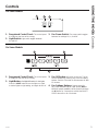 5
5
-
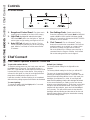 6
6
-
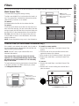 7
7
-
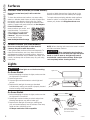 8
8
-
 9
9
-
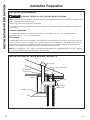 10
10
-
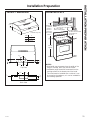 11
11
-
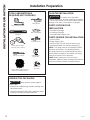 12
12
-
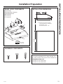 13
13
-
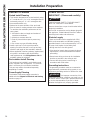 14
14
-
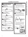 15
15
-
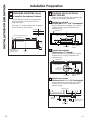 16
16
-
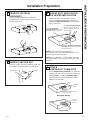 17
17
-
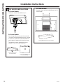 18
18
-
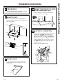 19
19
-
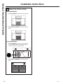 20
20
-
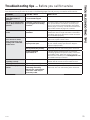 21
21
-
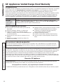 22
22
-
 23
23
-
 24
24
-
 25
25
-
 26
26
-
 27
27
-
 28
28
-
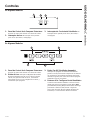 29
29
-
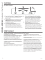 30
30
-
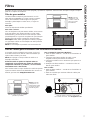 31
31
-
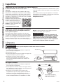 32
32
-
 33
33
-
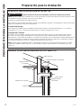 34
34
-
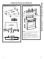 35
35
-
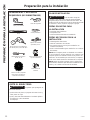 36
36
-
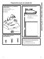 37
37
-
 38
38
-
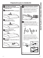 39
39
-
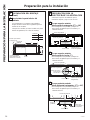 40
40
-
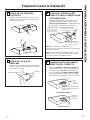 41
41
-
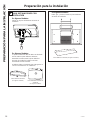 42
42
-
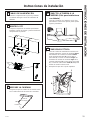 43
43
-
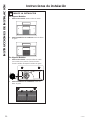 44
44
-
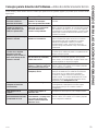 45
45
-
 46
46
-
 47
47
-
 48
48


GE JVX5300BJTS Guía de instalación
- Categoría
- Campanas de cocina
- Tipo
- Guía de instalación
- Este manual también es adecuado para
En otros idiomas
- English: GE JVX5300BJTS Installation guide
Documentos relacionados
-
GE Profile JVX3300SJSS Manual de usuario
-
GE JVX3300SJSS El manual del propietario
-
-
-
GE Appliances UVC7300SLSS El manual del propietario
-
-
GE Artistry Series JVX5360DJBB El manual del propietario
-
-
-