
Español p. 13
ITEM #0805278
LANDSCAPE LOW VOLTAGE
TRANSFORMER
ATTACH YOUR RECEIPT HERE
Serial Number
Purchase Date
Questions, problems, missing parts? Before returning to your retailer, call our customer
service department at 1-800-554-6504, 8 a.m. - 4:30 p.m, EST, Monday - Friday.
This instruction sheet covers the installation of the following Kichler® Transformers: 12217
200 WATT DIGITAL TRANSFORMER Input: 120VAC 60Hz 2A max. Output: 12VAC/15VAC 200VA max.
Read these instructions carefully before installing this unit. Save all safety warnings and instructions for
future reference.
• This device is only accepted for use as a component of a landscape lighting system where the suitability of
the combination shall be determined by National Electric Code or local authorities having jurisdiction.
• WARNING: Risk of electric shock, use only with low voltage landscape xtures and accessories. DO not use
with swimming pool or spa lighting xtures. Do not submerge transformer.
• Caution: Use only with maximum 180 watt, 180VA lamp load and a minimum 60 watt lamp load as speci-
ed below in Finding Transformer Load.
• Do not connect two or more power supplies in parallel.
• Do not touch the product. It may get hot during normal use.
• Suitable for indoor or outdoor use.
• WARNING: Risk of Fire. If installation involves running wiring through a building structure, special wiring
methods are needed. Consult a qualied electrician.
• Transformer should be mounted close to power source. Extension cords should not be used with this unit.
• WARNING: RISK OF ELECTRIC SHOCK. Install power unit 5 feet (1.525m) or more from any pool, spa, or
fountain.
(a) indoor within 10 feet (3.05m) of a pool, spa or fountain, or
(b) outdoor, connect power to unit to a receptacle protected by a GFCI.
• WARNING: Risk of Electric Shock. When used outdoors, install only to a 115/120 volt hood covered Class-A
GFCI protected receptacle, marked “Wet Location”, that is weatherproof with the power unit connected to
the receptacle. If one is not provided, contact a qualied electrician for proper installation. Ensure that the
power unit and cord do not interfere with completely closing the receptacle cover.
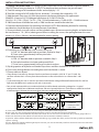
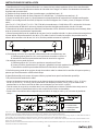
• Mount the rain-tight transformer at least one 1ft (.305m) above ground level with the wire terminals facing
down. NOTE: Do not energize transformer until installation of system is complete.
• Direct burial rated wire is to be buried a maximum of 6” (152.4mm) beneath the surface of the ground.
• Risk of re. Do not place insulation under terminal plate. Check connection after installation.
1
Kichler® is a registered trademark of
The L.D. Kichler Co. All Rights Reserved.
MODEL #12217

2
1) Finding Transformer Load: Low voltage systems require the use of a transformer to reduce standard
120-VOLT power from your home to 12-VOLTS. To determine the transformer size you will need:
A) Total the wattage of all incandescent bulbs and multiply by 1.25
B) Total the wattage of all LED bulbs/xtures, divide by .7 & multiply that subtotal by 1.25
C) Add the totals from steps A & B for the minimum transformer wattage or VA requirement.
EXAMPLE: A layout of (4) 15W halogen bulb xtures & (5) 6W LED xtures;
((4)x15)x1.25 = 75W , [((5)x6)/.7]x1.25 = 75W , 75W of incandescent + 53.6W of LED = 128.6W minimum.
A 100W transformer would be too small; a 150W transformer would be the ideal size.
2) Determine desired location for mounting transformer. NOTE: When deciding location for mounting
consideration should be taken for the requirements listed above.
3) To mount directly to a wall surface, use the included screws. Minimum mounting height, to the bottom of
the transformer, is 1 ft. (.305 m) above ground. When installing the screws, the spacing between the screw
centers is 3-9/16 in. (90 mm). See the template for correct spacing.
4) If mounting to a solid surface such as wood, siding, etc;
A) Drill 1/8” diameter pilot holes at positions marked in Step 3.
B) Drive screws approximately half way into holes.
If mounting to drywall:
A) Drill 1/4” diameter holes at positions marked in Step 3.
B) Push plastic anchors into holes and tap until ush.
C) Drive screws approximately half-way into plastic anchors.
5) Slip large portion of keyholes over head of top screws and allow transformer to slide down.
6) Drive screw through bottom slot and tighten until transformer is secure.
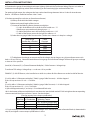
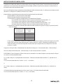
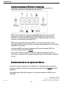
7) Choose cable run layout:
INSTALLATION INSTRUCTIONS
• Group xtures into zones by distance from the transformer (examples: 0-50', 50-75' and 75-100'). Do
not have a xture that is 10' away from the transformer on the same cable run as a xture that is 100'
away.
• Try to center load your runs as much as possible to minimize the voltage dierential between the rst and last
light (one volt dierence is optimum, two volts is too much).
• Run several separate cable runs to reduce the load per cable, thereby minimizing voltage loss. A typical
conguration would have a 200-watt transformer with two separate cable runs. Each cable run would have a load
of between 60 to 120 watts, but no more than 180 watts combined for the entire layout.
T
A) B)
E)D)
T
TT
LLLL
LLLL
LLLL
LLLL
LLLL
LLLL
C)
T
LLLL
LLLL
T
L = Light Fixture
= Transformer
= Landscape Cable
A) Series - Most common. The cable is run as one long run with lights located along the run.
B) Split - Run up to the recommended maximum distance in two or more directions from the transformer.
C) Tee - Allows more even distribution of power to the center of a run or to a run some distance away. Heavier gauge cable or a
double run should be used to make the tee. All cable to cable connections should be soldered.
D) Split Tee - Allows uniform distribution of power to both legs (e.g. to both sides of the yard). It's like doing a Split layout with Tee
layout in each leg.
E) Loop - Allows for relatively uniform light output - However, you must be extremely careful to connect the same wire ends to the
proper transformer terminals.
1ft
(.305m)

INSTALLATION INSTRUCTIONS
3
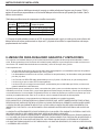
8) Determine the gauge of Low Voltage Landscape Lighting Cable and the Transformer Voltage Tap to use in order to
avoid excessive voltage drop, which leads to dimming or non-functioning lights at the end of the wire.
For optimum light output, the voltage at the lamp socket should range between 10.8 to 12 volts for incandescent
xtures. LED xtures should be between 10 to 14 volts.
(Calculate separately for each wire run from the transformer):
A) Add up all the individual bulb wattages.
B) Measure the total length of the wire run.
C) Use one of the following xture placement multipliers:
• If > 60% of the xtures are in the rst half of a cable run = .75
• If the xtures are spaced evenly along the run = 1
• If > 60% of the xtures are in the last half of a cable run = 1.25
• If 100% of the xtures are on the last half of a cable run = 2
D) Select the wire gauge Cable Constant value (Thicker wire is better as it drops less voltage)
E) To help boost the voltage, to compensate for the voltage drop on longer runs, this transformer comes with
both a 12V and 15V tap. Select the combination of wire gauge and transformer Voltage TAP that will give you a voltage
as close to 12V as possible.
(Load (W) x Distance (Ft.)) x (Fixture Placement Multiplier) / Cable Constant = Voltage drop.
Transformer TAP voltage - Voltage Drop = as close to 12V as possible.
EXAMPLE: (5) 6W LED xtures, to be installed on an 80 ft. wire, where all of the xtures are on the last half of the wire.
(5) x 6W x 80ft. x 2 (Placement multiplier)/ 7500 (12 gauge Cable Constant) = .64 Volts dropped.
If the 12V tap were used 12 -.64 = 11.36 Volts.
OR
(5) x 6W x 80ft. x 2 (Placement multiplier)/ 2200 (16 gauge Cable Constant) = 2.18 Volts dropped.
If the 15V tap were used 15 – 2.18 = 12.82 Volts.
9) Split cable approximately 3”, and strip 1/2” insulation o each wire.
10) On the bottom of the terminal block push one bare wire into the hole marked “COM” and tighten the corresponding
screw on terminal block face until wire is secure. (See chart below)
[Chart for terminal screw torque specication]
11) Push remaining bare wire into the appropriate voltage TAP as marked on bottom of terminal block (as determined in
step 8E) and tighten screw to torque specications in chart.
Wire Gauge
(smaller No. is thicker)
18
16
14
12
10
Cable
Constant
1380
2200
3500
7500
11920
Wire Size
MAX Number
of Conductors
Tightening Torque
#12
#10
#8
8
4
1
3.6 - 4.0 N-m [32-35 in-lbs]
3.6 - 4.0 N-m [32-35 in-lbs]
3.6 - 4.0 N-m [32-35 in-lbs]

INSTALLATION INSTRUCTIONS
4
Landscape Lighting Warranty and Limitations
Subject to Kichler’s General Warranty and Limitations and aside from the exceptions noted below, Kichler
warrants that Landscape Lighting Products whose model numbers begin with the numbers “28” will be free
from defects in material and workmanship for seven (7) years. The exceptions are:
• Low voltage landscape lighting aluminum housings and the product exterior nishes on them are
warranted for ve (5) years.
• Electronic power supplies, excluding timers and photocells, are warranted for ten (10) years.
• OEM LED Light Bulbs are warranted for ve (5) years or 25,000 hours, whichever comes rst.
• Non-LED Light bulbs carry no warranty.
• Non-Kichler branded LED bulbs supplied by, but not manufactured by Kichler carry no warranty
other than manufacturer’s warranty.
Certain acid-loving plants such as arborvitae, pine trees, and others must not be exposed to light of any
kind for more than 18 hours a day as these plants need time to sleep and allow photosynthesis to naturally
occur. As a result, Kichler warranties do not cover plants that die or burn because of continuous light shined
on them. This is not a defect but the inherent nature of such plants.
Substituting another manufacturer’s product and/or components will render the warranty completely void.
THIS WARRANTY GIVES YOU SPECIFIC LEGAL RIGHTS. YOU MAY ALSO HAVE OTHER RIGHTS WHICH VARY
FROM STATE TO STATE. SOME STATES DO NOT ALLOW LIMITATIONS ON HOW LONG AN IMPLIED WARRANTY
LASTS OR THE EXCLUSION OR LIMITATION OF INCIDENTAL OR CONSEQUENTIAL DAMAGES SO THE ABOVE
LIMITATIONS OR EXCLUSIONS MAY NOT APPLY TO YOU.
THE FOREGOING WARRANTY IS IN LIEU OF ALL OTHER WARRANTIES, EXPRESS OR IMPLIED, INCLUDING
THOSE OF MERCHANTABILITY, FITNESS FOR ANY PARTICULAR PURPOSE OR INFRINGEMENT. ORIGINAL
PURCHASER SHALL IN NO EVENT BE ENTITLED TO, AND KICHLER LIGHTING SHALL NOT BE LIABLE FOR,
INDIRECT, SPECIAL, INCIDENTAL OR CONSEQUENTIAL DAMAGES OF ANY NATURE, INCLUDING BUT NOT
LIMITED TO LOSS OF PROFIT, PROMOTIONAL AND/OR MANUFACTURING EXPENSES, OVERHEAD, INJURY TO
REPUTATION AND/OR LOSS OF CUSTOMERS.

OPERATION
5
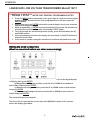
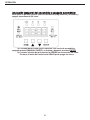
LANDSCAPE LOW VOLTAGE TRANSFORMER Model# 12217
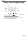
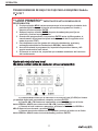
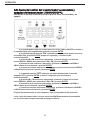
**READ FIRST** IMPORTANT GENERAL PROGRAMMING NOTES:
Press the MENU button repeatedly for the green light to rotate around the digital
display until the desired function to be programmed is lit and then press the
ENTER button.
Always then press the ENTER button after each setting to lock in your selection
and to finish programming.
While programming, if ENTER is not pressed within 30 seconds, the transformer
will select the current setting (after 10 seconds in TEST mode).
To scroll through the clock settings more quickly, press and hold down the UP
and DOWN arrows.
Once programming is finished the display will turn blank, it will NOT continue to
show the current time.
In the event of a power outage the transformer functions may need to be reset.
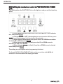
Setting the clock to local time
(Must be completed before any other programming):
a) Press MENU until the Green CLOCK LED indicator is lit and the digital display
is flashing, then press ENTER.
b) When AM and PM begins to flash, press the UP or DOWN arrow button to
select AM or PM and press ENTER.
c) When the hour begins to flash, press the UP or DOWN arrow to desired hour
and press ENTER.
d) When the minute begins to flash, press the UP or DOWN arrow to desired
minute and press ENTER.
The clock setting is now complete.
The Green Clock Light and the current time with AM/PM will remain lit for a minute
before the display goes blank.

OPERATION
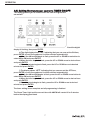
6
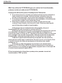
This transformer has 3 programming options to control the
landscape lights on/off function. Please
select one of the
options below and skip to the instruction step as noted:
n Setting the
transformer control to TIMER ON/OFF:
This setting allows you to control both the time the lights turn on and off. Skip to
step AA for programming.
n Setting the transformer control to PHOTO EYE AUTO ON/OFF:
This setting allows the PHOTO EYE to turn the lights on at dusk and off at dawn.
No timer settings are used. First follow Instructions BB to install the PHOTO EYE
Cable and then to step CC for programming.
n Setting the transformer control to PHOTO EYE ON / TIME OFF:
This setting allows the PHOTO EYE to turn the lights on and you set the time they
go off. First follow Instructions BB to install the PHOTO EYE Cable and then to
step DD for programming.

OPERATION
7
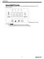
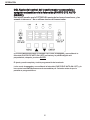
AA) Setting the transformer control to TIMER ON/OFF:
This setting allows you to control both the time the lights turn
on and off.
a) Press MENU until the Green TIME ON/OFF LED indicator is lit and the digital
display is flashing, then press ENTER.
b) The digit display shows “on” indicating that you can now set the ON time,
press ENTER (or wait 3 seconds and it will be selected automatically).
c) When the AM and PM begin to flash, press the UP or DOWN arrow button to
select AM or PM and press ENTER.
d) When the hour begins to flash, press the UP or DOWN arrow to desired hour
and press ENTER.
e) When the minute begins to flash, press the UP or DOWN arrow to desired
minute and press ENTER.
f) The display shows “
oFF” indicating that you can now set the OFF time,
press ENTER (or wait 3 seconds and it will be selected automatically).
g) When the AM and PM begins to flash, press the UP or DOWN arrow button to
select AM or PM and press ENTER.
h) When the hour begins to flash, press the UP or DOWN arrow to desired hour
and press ENTER.
i) When the minute begins to flash, press the UP or DOWN arrow to desired
minute and press ENTER.
The timer setting is now complete and all programming is finished.
The Green Timer Light and the current time with AM/PM will remain lit for 2 minutes
before the display goes blank.

OPERATION
8
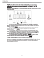
BB) If Using the PHOTO EYE for transformer control, first install the
PHOTO EYE Cable:
Photo EYE Mounting Location Advice:
Placing the sensor in areas receiving less sunlight at dusk (east side of
house, behind trees and bushes, under a deck) will have the transformer
come on earlier in the evening.
Mounting the photocell in brighter locations will have the transformer
come on when it has become darker out.
Avoid pointing the sensor at nighttime light sources such as windows,
porch lights, and street lights. This light may prevent the Photo Eye from
turning the transformer on.
A) Make sure power is off and transformer is NOT plugged into an
electrical outlet.
B) Unscrew the photocell connector dust cap from the transformer and
plug the photocell bi-pin connector into the mating “D” shape socket. Screw the
bi-pin cap onto the socket to provide a water tight connection. Note that the bi-
pin connector is polarized and can be inserted into the socket only one way.
C) Mount the photocell bracket on a wall or other solid surface with the
screws provided. Snap the sensor into the bracket. Route or coil the excess wire
to protect it from lawn mowers, trimmers, etc..
D) Plug power supply cord into standard 115/120 volt receptacle. NOTE:
The power supply cord must be plugged into a weather tight receptacle
equipped with a Ground Fault Interrupter (GFCI).
The photo eye operation can be tested by turning the transformer mode to TEST.

OPERATION
9
CC) Setting the transformer control to PHOTO EYE AUTO ON/OFF:
This setting allows the PHOTO EYE to turn the lights on at dusk and off at dawn.
No timer settings are used.
a) Press MENU until the Green PHOTO EYE AUTO ON/OFF LED indicator is lit and the
digital display is flashing, then press ENTER.
The setting is now complete and all programming is finished.
The Green PHOTO EYE AUTO ON/OFF Light and the current time with AM/PM will
remain lit for 2 minutes before the display goes blank.

OPERATION
10
DD) Setting the transformer control to PHOTO EYE ON / TIMER
OFF:
This setting allows the PHOTO EYE to turn the lights on and you set the time they
go off.
a) Press MENU until the Green PHOTO EYE ON TIMER OFF LED indicator
is lit, then press ENTER.
b) The display shows “oFF” indicating that you can now set the OFF time, press
ENTER (or wait 3 seconds and it will be selected automatically).
c) When AM and PM begins to flash, press the UP or DOWN arrow button
to select AM or PM and press ENTER.
d) When the minute begins to flash press the UP or DOWN arrow to
desired hour and press ENTER.
e) When the minute begins to flash, Press Up or DOWN arrow to desired
minute and press ENTER.
The setting is now complete
and all programming is finished.
The Green PHOTO EYE ON TIMER OFF Light and the current time with AM/PM will
remain lit for 2 minutes before the display goes blank.

OPERATION
11
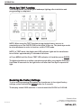
Manual ON/OFF Override:
This setting allows you bypass all programming modes and manually turn the
lights on and off.
a) Press MENU until the Green MANUAL ON/OFF LED indicator is lit and
then press ENTER.
b) Press the UP arrow button to turn on the lights.
Press the DOWN arrow button to turn off the lights.

Rev. 09-09-19
Kichler® is a registered trademark of
The L.D. Kichler Co. All Rights Reserved
Printed in China
OPERATION
12
Photo Eye TEST Function:
This setting allows you to test your landscape lighting after installation and
programming is completed:
NOTE: When using the TEST function during daylight hours, be sure to
completely cover the PHOTO EYE for the lights to turn on. The photo eye needs
to sense darkness in order to function, even in TEST mode.
NOTE: In TEST mode, the display and LED indicator lights on the transformer
turn off after approximately 10 seconds of idle time.
a) Press MENU until the Green TEST LED indicator is lit and then press ENTER.
The lights should turn on within a couple seconds after covering the Photo Eye.
It will take 30 seconds for the light to turn off after the Phot Eye is exposed to
light.
Restoring the Factory Settings:
To clear all programming and restore the transformer to its original factory
settings, press and hold the ENTER button for 3 seconds.
The display shows 88:88 and after 1 second resets the CLOCK to 12:00 AM.

ITEM #0805278
TRANSFORMADOR DE BAJO
VOLTAJE PARA PAISAJISMO
Esta cha de instrucciones cubre la instalación de los siguientes transformadores Kichler®: 12217
TRANSFORMADOR DIGITAL DE 200 W Alimentación: 120VAC 60Hz 2A máximo. Salida:12VAC/15VAC 200VA máximo.
Lea con cuidado estas instrucciones antes de instalar esta unidad. Guarde todas las advertencias de seguridad e
instrucciones para referencia futura.
• Este dispositivo sólo es aceptado para su uso como componente de un sistema de iluminación del paisaje, donde la
idoneidad de la combinación se determinará por el Código Eléctrico Nacional o las autoridades locales competentes.
• ADVERTENCIA: Riesgo de electrocución; utilícelo únicamente con lámparas y accesorios de bajo voltaje
para paisajismo. NO lo utilice con lámparas para piscinas o spas. No sumerja el transformador.
• Precaución: Úselo únicamente con una carga de lámpara máxima de 180 vatios y carga mínima de 60 vatios, según se
especica a continuación en Determinar la carga del transformador.
• No conecte dos o más alimentadores de corriente en paralelo.
• No toque el producto. Se puede calentarse durante el uso normal.
• Apto para usarse en interiores o exteriores.
• El transformador debe montarse cerca de la fuente de alimentación. No deben utilizarse extensiones eléctricas con
esta unidad.
• ADVERTENCIA: RIESGO DE ELECTROCUCIÓN. Instale la unidad de alimentación a 1.525 metros (5 ft) o más de distan-
cia de una piscina, spa o fuente.
(a) en interiores, a una distancia de 3.05 metros (10 ft) o menos de una piscina, spa o fuente, o
(b) en exteriores, conecte la alimentación a la unidad en un receptáculo protegido por un interruptor
de circuito de accionamiento rápido (GFCI).
ADVERTENCIA: Riesgo de electrocución. Cuando se use en exteriores, instálelo únicamente a un receptáculo protegi-
do de 115/120 voltios GFCI Clase A cubierto con capuchón, marcado “Wet Location” (ubicación húmeda) que sea
impermeable, con la unidad de alimentación conectada al receptáculo. Si no se proporciona uno, contacte a un
electricista calicado para la instalación adecuada. Asegúrese de que la unidad alimentadora y el cable no intereran
con el cierre total de la cubierta del receptáculo.
• ADVERTENCIA: Riesgo de incendio. Si la instalación involucra pasar cable por la estructura de una edicación, se
necesitan métodos de cableado especiales. Consulte con un electricista calicado.
• Monte el transformador impermeabilizado contra la lluvia al menos a 30.5 centímetros (1 ft) sobre el nivel del suelo
con las terminales de los cables mirando hacia abajo. NOTA: No conecte el transformador hasta que haya terminado
por completo la instalación del sistema.
• Los cables homologados para enterrarse directamente se deben enterrar a un máximo de 152.4 milímetros (6”)
debajo de la supercie del suelo.
• Riesgo de incendio, no coloque aislante debajo de la conexión plate. Check terminal despues de la
instalación.
13
Kichler® es una marca registrada de The L.D.
Kichler Co. Todos los derechos reservados.
MODELO #12217
¿Preguntas, problemas, piezas faltantes? Antes de devolverlo a la tienda, llame a nuestro
departamento de servicio al cliente al 1-800-554-6504, de 8:00 a.m. a 4:30 p.m. hora del
Este (EST), de lunes a viernes.
ADJUNTE SU RECIBO AQUÍ
Número de serie
Fecha de compra

14
1) Identicación de la carga del transformador: Los sistemas de bajo voltaje requieren del uso de un transformador
para reducir la alimentación eléctrica estándar de 120 voltios de su hogar a 12 voltios. Para determinar el tamaño de
transformador que necesitará:
A) Totalizar el vataje de todos los focos incandescentes y multiplicarlo por 1.25.
B) Totalizar el vataje de todos los focos/lámparas LED, dividirlo por .7 y multiplicar ese total por 1.25.
C) Sumar los totales de los pasos A y B para determinar el requerimiento de vataje mínimo o VA del transformador.
EJEMPLO: una conguración de cuatro (4) lámparas con focos halógenos de 15 vatios y cinco (5) lámparas LED de 6
vatios:
((4)x15)x1.25 = 75W, [((5)x6)/.7] x1.25 = 75W, 75W de luz incandescente + 53.6W de luz LED = mínimo de 128.6 vatios.
Un transformador de 100 vatios sería muy pequeño; el tamaño ideal del transformador sería de 150 vatios.
2) Determine la ubicación deseada para montar el transformador. NOTA: Al decidir la ubicación para el montaje, debe
tener en cuenta los requerimientos mencionados.
3) Para el montaje directo en la supercie de una pared, use los tornillos incluidos. La altura mínima de montaje hasta
la parte inferior del transformador es de .305 m (1 ft) sobre el suelo. Al instalar los tornillos, el espaciado entre los
centros de los tornillos es de 90 mm (3-9/16 in). Vea el espaciado correcto en la plantilla.
4) Si el montaje se hará en una supercie sólida como madera, recubrimientos, etc.;
A) Perfore agujeros piloto de 1/8 in en las posiciones marcadas en el Paso 3.
B) Atornille los tornillos aproximadamente hasta la mitad en los agujeros.
Si el montaje es en un panel de pared:
A) Perfore agujeros de 1/4 in en las posiciones marcadas en el Paso 3.
B) Inserte las anclas de plástico en los agujeros y golpéelas hasta que queden al ras del panel.
C) Atornille los tornillos aproximadamente hasta la mitad de las anclas plásticas.
5) Deslice la parte grande de los agujeros de ojo de cerradura sobre las cabezas de los tornillos de la parte superior, y
permita que el transformador se deslice hacia abajo.
6) Atornille el tornillo por la ranura de la parte inferior y apriete hasta que el transformador quede jo.
7) Elija el diseño del trazado de los cables:
• Agrupe las lámparas en zonas de acuerdo con la distancia desde el transformador [ejemplos: 0-15 m, 15-23 m y
23-30 m (0-50, 50-75 y 75-100 ft)]. No se puede tener una lámpara que esté a 3.05 m (10 ft) de distancia del
transformador en el mismo recorrido de cable que una lámpara que esté a 30.5 m (100 ft).
• Trate de centrar la carga de los recorridos tanto como sea posible para minimizar el diferencial de voltaje entre la
primera y la última luz (una diferencia de un voltio es óptima, dos voltios es demasiado).
• Instale varios recorridos de cable independientes para reducir la carga por cable y, así, minimizar la pérdida de
voltaje. v
T
A) B)
E)D)
T
TT
LLLL
LLLL
LLLL
LLLL
LLLL
LLLL
C)
T
LLLL
LLLL
T
L = Light Fixture
= Transformador
= Landscape Cable
A) En serie: lo más común. El cable se extiende como un recorrido largo con las luces ubicadas a lo largo del recorrido.
B) Dividido: extender hasta la máxima distancia recomendada en dos o más direcciones desde el transformador.
C) En “T”: permite una distribución más uniforme de la energía al centro de un recorrido o hacia un recorrido que esté algo alejado. Se debe utilizar un cable de
mayor calibre o un recorrido doble de cable para hacer la “T”. Todas las conexiones de cable a cable deben soldarse.
D) “T” dividida: permite una distribución uniforme de la energía a los dos extremos (esto es, a ambos lados del patio). Es como hacer un diseño dividido con un
diseño en “T” en cada extremo.
E) Bucle: permite una salida relativamente uniforme de luz. Sin embargo, debe ser extremadamente cuidadoso al conectar los mismos extremos del cable a las
terminales adecuadas del transformador.
INSTRUCCIONES DE INSTALACIÓN
1ft
(.305m)

15
INSTRUCCIONES DE INSTALACIÓN
8) Determine el calibre del cable para la iluminación de bajo voltaje para paisajismo y la toma de tensión del transfor-
mador que se usará para evitar una caída excesiva del voltaje, que lleva a que las luces reduzcan su intensidad o no
funcionen hacia el extremo nal del cable.
Para una salida óptima de luz, el voltaje en el portalámparas debe estar entre 10.8 y 12 voltios para las lámparas incan-
descentes. Las lámparas LED deben estar entre 10 y 14 voltios.
(Haga el cálculo separadamente para cada tramo de cable desde el transformador):
A) Sume todos los vatios de los focos individuales.
B) Mida la longitud total de cada tramo de cable.
C) Use uno de los siguientes multiplicadores de colocación de lámparas:
• Si más del 60% de las lámparas están en la primera mitad del tramo del cable = .75
• Si las lámparas están espaciadas uniformemente a lo largo del tramo = 1
• Si más del 60% de las lámparas están en la última mitad del tramo del cable = 1.25
• Si el total (100%) de las lámparas están en la última mitad del tramo del cable = 2
D) Seleccione el valor de la constante del calibre del cable (el cable más grueso es mejor ya que tiene menor
caída de voltaje)
E) Para ayudar a optimizar el voltaje, para compensar la pérdida de voltaje en tramos más largos, este transfor
mador viene con tomas de tensión tanto de 12 voltios como de 15 voltios. Seleccione la combinación de
calibre del cable y una toma de voltaje del transformador que le proporcionará un voltaje lo más cercano
posible a 12 voltios.
(Carga (W) x Distancia (Pies)) x (Multiplicador de ubicación de lámparas) / Constante del cable = Caída de voltaje
Toma de voltaje del transformador - Caída de voltaje = lo más cercano posible a 12 voltios.
POR EJEMPLO: Cinco (5) lámparas LED de 6 vatios que se instalarán en un cable de 80 pies, en el que todas las lámpa-
ras están en la última mitad del cable.
(5) x 6 vatios x 80 pies x 2 (multiplicador de ubicación) / 7500 (constante del cable de calibre 12) = pérdida de .64
voltios.
Si se usó la toma de tensión de 12 voltios, 12- .64 = 11.36 voltios.
O
(5) x 6 vatios x 80 pies x 2 (multiplicador de ubicación) / 2200 (constante del cable de calibre 16) = caída de 2.18
voltios.
9) Divida el cable aproximadamente 8 cm (3 in) y pele 13 mm (1/2 in) del aislante de cada cable.
Si se usó la toma de tensión de 15 voltios, 15 - 2.18 = 12.82 voltios.
Constante del
cable
Calibre del cable
(el número menor
es más grueso)
1380
2200
3500
7500
11920
18
16
14
12
10

16
10) En la parte inferior del bloque terminal, empuje un cable pelado en el agujero con la marca “COM” y
apriete el tornillo correspondiente en el frente del bloque terminal hasta que quede jo el cable. (Vea la
tabla a continuación)
[Tabla de especicaciones de torque para tornillos terminales)
11) Empuje el cable pelado restante en el TAP de voltaje adecuado según se indica en la parte inferior del
bloque terminal (como se determinó en el paso 8C) y apriete el tornillo a las especicaciones de torque
proporcionadas en la tabla.
Tamaño
del cable
Número MÁX
de conductores
Torque de ajuste
#12
#10
#8
8
4
1
3.6 - 4.0 N-m [32-35 in-lbs]
3.6 - 4.0 N-m [32-35 in-lbs]
3.6 - 4.0 N-m [32-35 in-lbs]
ILUMINACIÓN PARA PAISAJISMO GARANTIA Y LIMITACIONES
Con sujeción a la Garantía General y a las Limitaciones de Kichler y aparte de las excepciones indicadas a continu-
ación, Kichler garantiza que los Productos de iluminación para paisajismo cuyos números de modelo comiencen con
los números “28” estarán libres de defectos en materiales y mano de obra por siete (7) años.
Las excepciones son:
• Las carcasas de aluminio de las luces de bajo voltaje para paisajismo y los acabados exteriores del producto
de estas carcasas están garantizados por cinco (5) años.
• Los alimentadores electrónicos de corriente, excluidos los temporizadores y las fotoceldas, están garantizados
por diez (10) años.
• Los Focos de luz OEM LED están garantizados por cinco (5) años o 25,000 horas, lo que suceda primero.
• Los focos de luz que no sean LED no tienen garantía.
• Los focos LED que no tengan la marca Kichler, suministrados pero no fabricados por Kichler, no tienen otra
garantía además de la del fabricante.
Algunas plantas que son atraídas por el ácido, como arbovitae, pinos y otras, no se deben exponer a luz de ninguna
naturaleza por más de 18 horas al día, ya que estas plantas necesitan tiempo para dormir y permitir que la fotosíntesis
ocurra naturalmente. Como resultado, las garantías Kichler no cubren las plantas que mueran o se quemen por la luz
continua proyectada sobre ellas. Esto no es un defecto, sino la naturaleza inherente de dichas plantas.
Sustituirlos con productos o componentes de otro fabricante invalidará por completo la garantía.
ESTA GARANTÍA LE OTORGA DERECHOS LEGALES ESPECÍFICOS. USTED TAMBIÉN PUEDE TENER OTROS
DERECHOS QUE VARÍAN DE ESTADO A ESTADO. ALGUNOS ESTADOS NO PERMITEN LIMITACIONES SOBRE
LA DURACIÓN DE UNA GARANTÍA IMPLÍCITA O LA EXCLUSIÓN O LIMITACIÓN DE DAÑOS INCIDENTALES O
INDIRECTOS; POR TANTO, LAS LIMITACIONES O EXCLUSIONES ANTERIORES PUEDEN NO APLICAR EN SU
CASO.
LA GARANTÍA ANTERIORMENTE DESCRITA REMPLAZA CUALQUIER OTRA GARANTÍA, EXPRESA O IMPLÍCITA,
INCLUÍDAS AQUELLAS DE COMERCIABILIDAD, ADECUACIÓN PARA CUALQUIER
PROPÓSITO PARTICULAR O INFRACCIÓN. EL COMPRADOR ORIGINAL EN NINGÚN CASO TENDRÁ DERECHO
A, Y KICHLER LIGHTING NO SERÁ RESPONSABLE POR, DAÑOS INDIRECTOS, ESPECIALES, INCIDENTALES O
CONSECUENTES DE CUALQUIER NATURALEZA, INCLUÍDOS SIN LIMITACIÓN, LA PÉRDIDA DE UTILIDADES,
LOS GASTOS PROMOCIONALES O DE FABRICACIÓN, LOS GASTOS GENERALES, EL DAÑO A LA REPUTACIÓN
Y LA PÉRDIDA DE CLIENTES.
INSTRUCCIONES DE INSTALACIÓN

OPERACIÓN
17
TRANSFORMADOR DE BAJO VOLTAJE PARA PAISAJISMO Modelo
N
o
12217
**LEER PRIMERO** IMPORTANTES NOTAS GENERALES DE
PROGRAMACIÓN:
Presione el botón MENU varias veces para que la luz verde gire alrededor de la
pantalla digital hasta que la función que se desea programar se ilumine y
después presione el botón ENTER.
Siempre presione el botón ENTER después de cada ajuste para fijar su
selección y finalizar la programación.
Cuando esté programando, si no presiona ENTER antes de 30 segundos, el
transformador seleccionará el ajuste actual (después de 10 segundos en el
modo de prueba TEST).
Para desplazarse por los ajustes del reloj más rápidamente, presione y
sostenga presionadas las flechas hacia ARRIBA y hacia ABAJO.
Una vez terminada la programación, la pantalla se pondrá en blanco y NO
seguirá mostrando la hora actual.
En caso de un corte de luz, es posible que se deban restablecer las funciones
del transformador.
Ajuste del reloj a la hora local
(Se debe realizar antes de cualquier otra programación):
a) Presione MENÚ hasta que el indicador LED verde del reloj (CLOCK) se ilumine
y la pantalla digital esté parpadeando; después, presione ENTER.
b) Cuando AM y PM comiencen a parpadear, presione el botón con la flecha
hacia ARRIBA o ABAJO para seleccionar AM o PM y presione ENTER.
c) Cuando la hora comience a parpadear, presione la flecha hacia ARRIBA o
ABAJO hasta la hora deseada y presione ENTER.
c) Cuando los minutos comiencen a parpadear, presione el botón con la flecha
hacia ARRIBA o ABAJO hasta el minuto deseado y presione ENTER.

OPERACIÓN
18
El ajuste del reloj ya está completo.
La luz verde del reloj (CLOCK) y la hora actual con AM/PM permanecerán encendidas
por un minuto antes de que la pantalla se ponga en blanco.
Este transformador tiene 3 opciones de programación para
controlar la función de encendido y apagado
(ON/OFF) de las
luces para paisajismo. Seleccione una de las siguientes
opciones y pase a la instru
cción del paso según se indica:
n Ajuste del control del transformador a encendido y apagado
del tem
porizador (TIMER ON/OFF):
Este ajuste le permite controlar la hora en que las luces se encienden y se
apagan. Pase al paso AA para la programación.
n Ajuste del control del transformador a encendido y apagado
automático de la fotocelda (PHOTO EYE AU
TO ON/OFF):
Este ajuste permite que la FOTOCELDA encienda las luces al anochecer y las
apague al amanecer. No se utilizan ajustes del temporizador. Primero, siga las
instrucciones BB para instalar el cable de la FOTOCELDA y pase después al
paso CC para la programación.
n Ajuste del control del transformador a encendido de la
fotocelda / hora de apagado (PHOTO EYE ON /
TIME OFF):
Este ajuste permite que la FOTOCELDA encienda las luces y usted defina la hora
en que se apagan. Primero, siga las instrucciones BB para instalar el cable de
la FOTOCELDA y pase después al paso DD para la programación.

OPERACIÓN
19
AA) Ajuste del control del transformador a encendido y
apagado del temporizador (TIMER ON/OFF):
Este ajuste le permite controlar la hora en que las luces se encienden y se
apagan.
a) Presione MENÚ hasta que el indicador LED verde (TIMER) ON/OFF se ilumine y
la pantalla digital esté parpadeando; después, presione ENTER.
b) La pantalla digital muestra “On” indicando que ahora puede ajustar la hora de
encendido (ON); presione ENTER (o espere 3 segundos y se seleccionará
automáticamente).
c) Cuando AM y PM comiencen a parpadear, presione el botón con la flecha
hacia ARRIBA o ABAJO para seleccionar AM o PM y presione ENTER.
d) Cuando la hora comience a parpadear, presione la flecha hacia ARRIBA o
ABAJO hasta la hora deseada y presione ENTER.
e) Cuando los minutos comiencen a parpadear, presione la flecha hacia ARRIBA
o ABAJO hasta el minuto deseado y presione ENTER.
f) La pantalla muestra “
Off” indicando que ahora puede ajustar la hora de
apagado (OFF); presione ENTER (o espere 3 segundos y se seleccionará
automáticamente).
g) Cuando AM y PM comiencen a parpadear, presione el botón con la flecha
hacia ARRIBA o ABAJO para seleccionar AM o PM y presione ENTER.
h) Cuando la hora comience a parpadear, presione la flecha hacia ARRIBA o
ABAJO hasta la hora deseada y presione ENTER.
i) Cuando los minutos comiencen a parpadear, presione la flecha hacia ARRIBA
o ABAJO hasta el minuto deseado y presione ENTER.
El ajuste del temporizador ya está completo y toda la programación ha terminado.
La luz verde del temporizador y la hora actual con AM/PM permanecerán encendidas
por 2 minutos antes de que la pantalla se ponga en blanco.

OPERACIÓN
20
BB) Si se utiliza la FOTOCELDA para el control del transformador,
primero instale el cable de la FOTOCELDA:
Consejo de ubicación para el montaje de la Fotocelda:
Si se coloca el sensor en áreas que reciben menos luz solar al atardecer
(lado oriental de la vivienda, detrás de árboles y arbustos, bajo una
terraza) el transformador se encenderá más temprano al anochecer.
Si se monta la fotocelda en ubicaciones más iluminadas, el transformador
se encenderá cuando se oscurezca más afuera.
Evite dirigir el sensor en horas de la noche a fuentes de luz como
ventanas, luces de patio y las luces de la calle. Esta luz puede impedir
que la Fotocelda encienda el transformador.
A) Asegúrese de que la alimentación esté apagada y de que el
transformador NO esté conectado a una toma eléctrica.
B) Desatornille del transformador la tapa protectora de polvo del conector
de la fotocelda e introduzca el conector del pin doble de la fotocelda en el
enchufe de acople con forma de “D”. Atornille la tapa del pin doble en el enchufe
para conseguir una conexión impermeable. Note que el conector de dos pines
es polarizado y solamente se puede insertar en el enchufe en un sentido.
C) Monte el soporte de la fotocelda en una pared o en otra superficie
sólida con los tornillos que se suministran. Encaje el sensor en el soporte. Guíe
o enrolle el exceso de cable para protegerlo de cortadoras de césped,
podadoras, etc.
D) Conecte el cable alimentador de corriente en un tomacorriente
estándar de 115/120 voltios. NOTA: El cable de alimentación de corriente se
debe conectar en un receptáculo impermeable, equipado con un interruptor de
circuito de accionamiento rápido (GFCI).
El funcionamiento de la fotocelda se puede probar pasando el modo del
transformador a TEST (prueba).

OPERACIÓN
21
CC) Ajuste del control del transformador a encendido y
apagado automático de la fotocelda (PHOTO EYE
AUTO
ON/OFF):
Este ajuste permite que la FOTOCELDA encienda las luces al anochecer y las
apague al amanecer. No se utilizan ajustes del temporizador.
a) Presione MENÚ hasta que el indicador LED verde de apagado y encendido de la
fotocelda (PHOTO EYE AUTO ON / OFF) se ilumine y la pantalla digital esté
parpadeando; después, presione ENTER.
El ajuste ya está completo y toda la programación ha terminado.
La luz verde de apagado y encendido de la fotocelda (PHOTO EYE AUTO ON / OFF) y la
hora actual con AM/PM permanecerán encendidas por 2 minutos antes de que la
pantalla se ponga en blanco.

OPERACIÓN
22
DD) Ajuste del control del transformador a encendido y
apagado automático de la fotocelda (PHOTO EYE
AUTO
ON/OFF):
Este ajuste permite que la FOTOCELDA encienda las luces y usted defina la hora
en que se apagan.
a) Presione MENU hasta que el indicador LED verde de encendido y
apagado automático de la fotocelda (PHOTO EYE AUTO ON/OFF) se ilumine y
después presione ENTER.
b) La pantalla muestra “oFF” indicando que ahora puede ajustar la hora de
apagado (OFF); presione ENTER (o espere 3 segundos y se seleccionará
automáticamente).
c) Cuando AM y PM comiencen a parpadear, presione el botón con la
flecha hacia ARRIBA o ABAJO para seleccionar AM o PM y presione ENTER.
d) Cuando la hora comience a parpadear, presione la flecha hacia
ARRIBA o ABAJO hasta la hora deseada y presione ENTER.
e) Cuando el minuto comience a parpadear, presione la flecha hacia
ARRIBA o ABAJO hasta el minuto deseado y presione ENTER.
El ajuste ya está completo y toda la programación ha terminado.
La luz verde de apagado y encendido de la fotocelda (PHOTO EYE AUTO ON / OFF) y la
hora actual con AM/PM permanecerán encendidas por 2 minutos antes de que la
pantalla se ponga en blanco.

OPERACIÓN
23
Anulación temporal del encendido y apagado automático:
Este ajuste le permite ignorar todos los modos de programación y encender y
apagar manualmente las luces.
a) Presione MENU hasta que el indicador LED verde de encendido y
apagado manual (MANUAL ON/OFF) se ilumine y después presione ENTER.
b) Presione el botón de la flecha hacia ARRIBA para encender las luces.
Presione el botón de flecha hacia ABAJO para apagar las luces.

Rev. 09-09-19
OPERACIÓN
24
Impreso en China
Kichler® es una marca registrada de The
L.D. Kichler Co. Todos los derechos reservados.
Función de prueba (TEST) de la Fotocelda:
Este ajuste le permite probar sus luces para paisajismo después de la
instalación y de haber completado la programación.
NOTA: Cuando use la función de prueba (TEST) durante las horas del día,
asegúrese de cubrir por completo la FOTOCELDA para que las luces se
enciendan. La fotocelda debe detectar la oscuridad para poder funcionar,
incluso en la modalidad de prueba (TEST).
NOTA: En la modalidad de prueba (TEST), las luces de la pantalla y de los
indicadores LED en el transformador se apagan aproximadamente 10 segundos
después de inactividad.
a) Presione MENU hasta que el indicador LED verde de prueba (TEST) se
encienda y después presione ENTER.
Las luces se deben encender en unos dos segundos después de cubrir la
Fotocelda, y se apagarán 30 segundos después de que la fotocelda se exponga
a la luz.
Restablecimiento de los ajustes de fábrica:
Para borrar toda la programación y restablecer el transformador a sus ajustes
originales de fábrica, presione y sostenga presionado el botón ENTER durante 3
segundos.
La pantalla muestra 88:88 y después de 1 segundo restablece el RELOJ a las
12:00 AM.
-
 1
1
-
 2
2
-
 3
3
-
 4
4
-
 5
5
-
 6
6
-
 7
7
-
 8
8
-
 9
9
-
 10
10
-
 11
11
-
 12
12
-
 13
13
-
 14
14
-
 15
15
-
 16
16
-
 17
17
-
 18
18
-
 19
19
-
 20
20
-
 21
21
-
 22
22
-
 23
23
-
 24
24


Kichler 0805278 Manual de usuario
- Tipo
- Manual de usuario
- Este manual también es adecuado para
En otros idiomas
- English: Kichler 0805278 User manual
Documentos relacionados
Otros documentos
-
GE 15112 Instrucciones de operación
-
Progress Lighting P8518-31 Guía de instalación
-
-
 Kichler Lighting 15515CBR Manual de usuario
-
 Kichler Lighting 15CS75SS Manual de usuario
-
 Kichler Lighting 15pr200SS Manual de usuario
-
 Utilitech TM-074 Instrucciones de operación
-
Portfolio 8201080378 Guía de instalación
-
 Kichler Lighting 16027SS30 Manual de usuario
-
Intermatic HB800 Series Installation And User Instructions Manual


