Toshiba RAC-WK1823ESCWR Guía del usuario
- Tipo
- Guía del usuario

USER MANUAL
Safety Precautions
Operating Instructions
Installation Instructions
Remote Control and App
Instructions
Troubleshooting Tips
Care and Cleaning
RAC-WK1823ESCWRU (18,000 BTU)
Window Type
Room Air Conditioner
Warning notices: Before using this product,
please read this manual carefully and keep
it for future reference.
change without prior notice for product
improvement. Consult with your dealer or
the manufacturer for details.
www.toshiba-lifestyle.com0202 - 70 - A noisrev
S
a
f
Op
I
n
s
version B - 09 - 2022 (PREVIEW01)

Page 2 User Manual
Read This Manual
Inside you’ll nd many helpful hints on how to use and maintain your air conditioner properly. Just
a little preventive care on your part can save you a great deal of time and money over the life of
your air conditioner. You’ll nd many answers to common problems in the troubleshooting tips -
you should be able to x most of them quickly before calling service. These instructions may not
cover every possible condition of use, so common sense and attention to safety is required when
installing, operating and maintaining this product.
• This appliance is not intended for use by persons (including children) with reduced physical,
sensory or mental capabilities or lack of experience and knowledge, unless they have been
given supervision or instruction concerning use of the appliance by a person responsible for
their safety.
• For support, please call the Service Center at 1-855-204-5313.
• Children should be supervised to ensure that they do not play with the air conditioner.
• The appliance shall be installed in accordance with national wiring regulations.
• Do not operate your air conditioner in a humid room such as a bathroom or laundry room.
CAUTION

User Manual Page 3
To prevent injury to the user or other people and property damage, the instructions shown here must be
followed. Incorrect operation due to ignoring of instructions may cause harm or damage. The level of risk
is shown by the following indications.
Safety
Precautions
WARNING This symbol indicates a hazardous situation which, if not avoided,
could result in death or serious injury.
CAUTION
This symbol indicates a hazardous situation, which, if not avoided,
could result in minor or moderate injury.
NOTICE
This symbol addresses practices not related to physical injury.
• Be sure the air conditioner has been securely and correctly installed according to the
installation instructions in this manual. Save this manual for possible future use in removing or
installing this unit.
• Plug in power cord plug properly.
re due to excess heat generation.
• Do not modify power cord length or share the outlet with other appliances as it may cause
re due to overheating.
ective grounding.
Incorrect grounding may cause electric shock.
• Unplug the unit if you notice unusual sounds or smells or smoke coming from it.
re and electric shock.
• Ventilate room before operating the air conditioner if there is a gas leakage from another
appliance.
• Do not operate or stop the unit by inserting or pulling out the power cord plug.
• Do not operate with wet hands or in very humid environments.
It may cause electric shock.
• Do not allow water to come into contact with any electric parts.
It may cause failure or electric shock.
• Do not use the socket if it is loose or damaged.
re and electric shock.
• Do not use or keep the power cord close to heating appliances.
re and electric shock.
• Do not use any devices or materials for installation that are not recommended in this manual.
• Do not disassemble or modify unit.
It may cause failure and electric shock.
WARNING

Page 4 User Manual
Safety
Precautions
• Do not damage or use an alternate power cord.
re and electric shock.
If the power cord is damaged, it must be replaced by the manufacturer or an authorized service
ed person in order to avoid a hazard.
ow straight into persons to avoid possible health hazard.
• Do not open the unit during operation.
It may cause electric shock.
ammable gas or combustibles, such as gasoline, benzene,
thinner, etc.
re.
• Do not let children hang on the air conditioner or bracket.
A serious injury may occur.
re hazard or electric shock. Do not use an extension cord or an adaptor plug. Do not
remove any prongs from the power cord.
re hazards, proper
grounding is important. The power cord is equipped with a three-prong grounding plug for
protection against shock hazards.
• Your air conditioner must be used in a properly grounded wall receptacle. If the wall receptacle
you intend to use is not adequately grounded or protected by a time delay fuse or circuit
ed electrician install the proper receptacle. Ensure the receptacle is
accessible after the unit installation.
• Be sure the electrical service is adequate for the model you have chosen. This information can be
found on the serial plate, which is located on the side of the cabinet and behind the grille.
• Do not drink the drain water. It may contain mold and bacteria that can lead to death if ingested.
lter is to be removed, do not touch the metal parts of the unit.
It may cause injury.
the circuit breaker.
re, electric shock or injury.
• Do not place obstacles around air inlets or inside of air outlet.
It may cause failure or accident.
• Clean with a soft cloth only. Do not use strong detergents that contain wax or thinners as it may
damage the product.
• Use caution when unpacking and installing. Sharp edges could cause injury.
• Do not clean the air conditioner with water.
Water may enter the unit and degrade the insulation which could lead to electric shock.
WARNING
CAUTION

User Manual Page 5
Safety
Precautions
ow.
This could injure the pet or harm the plant.
• Hold the plug by the head of the power plug when taking it out.
Otherwise, it may cause electric shock and damage.
• Ensure that the installation is properly secured to prevent the product from potentially falling.
• Do not place heavy objects on the power cord and ensure that the cord is not compressed.
re or electric shock.
the circuit breaker. Isolate supply by
ed service technician.
ect gas
combustion.
• Do not use for any purpose other than room comfort.
Do not use this air conditioner to preserve precision devices, food, pets, plants, and art objects.
It may cause deterioration.
the main power switch if the unit is not to be used for an extended time.
lter once every two weeks.
lters may cause failure.
CAUTION

Page 6 User Manual
Safety
Precautions
WARNING
ammable refrigerant.
If the refrigerant is leaked and exposed to an external ignition source,
re.
CAUTION This symbol shows that the operation manual should be read carefully.
CAUTION This symbol shows that a service personnel should be handling this
equipment with reference to the installation manual.
CAUTION This symbol shows that information is available such as the operating
manual or installation manual.
EXPLANATION OF SYMBOLS DISPLAYED ON THE UNIT
• Do not try to accelerate the defrosting process or methods of cleaning that are not
recommended by the manufacturer.
• The appliance shall be stored in a room without a continuously operating ignition source (for
ames or an operating gas appliance) or an ignition source (for example, an
operating electric heater) close to the appliance. The appliance shall also be stored in a room
without ignition sources.
• Do not pierce or burn.
• Be aware that the refrigerants may not contain an odor.
• Keep ventilation openings clear of obstruction.
• Unit is only to be serviced by a Toshiba authorized servicer, please call Customer Service at
1-855-204-5313 for support.
• Flammable refrigerant R32 is used within air conditioner. Please follow the instructions carefully
to handle, install, clean, and service the air conditioner to avoid damage or hazard. Do not
ed agency for proper disposal.
re or devices that generate spark/arcing shall be around the air conditioner to avoid
ammable refrigerant used. Please follow the instructions carefully to
store or maintain the air conditioner to prevent mechanical damage from occurring.
WARNING
Caution: Risk of fire/
flammable materials
(Required for R32/R290 units only)
IMPORTANT NOTE: Read this manual
carefully before installing or operating
your new air conditioning unit. Make sure
to save this manual for future reference.

User Manual Page 7
The power supply cord with this air conditioner
contains a current detection device designed
re.
In the event that the power supply cord is
damaged, it can not be repaired. It must be
replaced with a cord from the manufacturer.
.
• Always make sure the RESET button is pushed in for correct operation.
• The power supply cord must be replaced if it fails to reset when either the TEST button is pushed,
or it can not be reset. Please contact Customer Service.
Grounding type wall receptacle
Do not, under any
circumstances, cut,
remove or bypass
the grounding prong.
Power supply cord with 3-prong grounding
plug and current detection device.
The power supply cord contains a current
measuring device that detects damage to the
power cord. Test your power supply cord as
follows:
1. Plug in the air conditioner.
2. The power supply cord will have TWO
buttons on the plug head. Press the TEST
button. You will notice a click as the RESET
button pops out.
3. Press the RESET Button. You will notice a click
as the button engages.
4. The power supply cord is now supplying
electricity to the unit. (On some products this
is also indicated by a light on the plug head.)
RESET
TEST
Plug in & press RESET
NOTICE
NOTICE
Safety
Precautions

Page 8 User Manual
Operating
Instructions
RAC-WK18 Models
Gurgle/Hiss
Gurgling or hissing
noises may be heard due
to refrigerant flowing
through evaporator
during normal operation.
Sound of Rushing Air
In front of the unit, you
may hear the sound of
rushing air being moved
by the fan.
Vibration
Unit may vibrate and make
noise because of poor wall
or window construction or
incorrect installation.
Trickling Sound
Droplets of water
hitting condenser
during normal
operation may cause
a trickling sound.
High Pitched Sound
High efficiency compressors may
have a high pitched sound during
cooling cycle.
All the pictures in this manual are for illustrative purposes only. The actual appearance of the air
conditioner you purchased may vary slightly, but its operation and functions will be similar.
NOTICE
This air conditioner is designed to be operated under the following conditions:
Cooling Operation
Outdoor temp.: 64 ~ 109°F / 18 ~ 43°C
Indoor temp.: 62 ~ 90°F / 17 ~ 32°C
To reduce the risk of re, electrical shock, or injury to people or property, read the SAFETY
PRECAUTIONS before operating this appliance.
WARNING
• The relative humidity of room should be less than 80%. If the unit is used in a condition with a
relative humidity over 80%, there will be condensed water on the surface of the unit.
• Performance may be reduced outside of these operating temperatures.
NOTICE

User Manual Page 9
Operating
Instructions
To begin operating the air conditioner, follow these steps:
1. Set the temperature to the coldest setting.
2. Set the control to HIGH COOL.
ow (see Air Directional Louvers).
nd most comfortable.
ow inside and outside are not obstructed.
ow Left
or Right, or Up and Down (optional on some models)
throughout the room as needed.
Move the Levers from side to side until the desired
LEFT/RIGHT direction is obtained.
ow
UP/DOWN as needed.
Levers
Air Direction
and then on again, or when changing from cool to
fan and back to cool. This prevents damage from occurring to the compressor.
NOTICE
The Fresh Air Vent allows the air conditioner to:
1. Recirculate inside air – Vent Closed (See Fig. A)
2. Draw fresh air into the room - Vent Open (See Fig. B)
3. Exchange air from the room and draw fresh air into the room - Vent and Exhaust Open (See Fig. C).
FRESH AIR VENT CONTROL
Fig. A (VENT CLOSED) Fig. B (VENT OPEN) Fig. C (VENT & EXHAUST OPEN)

Page 10 User Manual
TO TURN UNIT ON OR OFF:
.
NOTE: The unit will automatically initiate the Energy
Saver function under Cool, Dry, Auto modes.
TO CHANGE TEMPERATURE SETTING:
Press UP/DOWN button to change temperature
setting.
NOTE: Press or hold either UP ( ) or DOWN ( )
button until the desired temperature is seen on the
display.
This temperature will be automatically maintained
anywhere between 62°F (17°C) and 86°F (30°C). If
you want to display the actual room temperature,
see To Operate on Fan Only section.
TO ADJUST FAN SPEEDS:
Press the Fan Button to change the fan speed
between four settings – Auto, Low, Med, or High. The
fan will operate on Low Speed automatically when
set to Dry Mode.
On Auto mode,the fan operates on Auto fan speed
automatically and cannot be changed.
SLEEP FEATURE:
Press Sleep button to initiate the sleep mode. In
this mode the selected temperature will increase by
2°F (1°C) 30 minutes after the mode is selected.
The temperature will then increase by another 2°F/
1(or 2)°C after an additional 30 minutes. This new
temperature will be maintained for 7 hours before it
returns to the originally selected temperature.
The Sleep mode program can be cancelled at any time
during operation by pressing the Sleep button again.
CHECK FILTER FEATURE:
The Check Filter feature is a reminder to clean the
air lter for a more ecient operation. The light
will illuminate after 250 hours of operation. After
cleaning the lter, press the Filter button to reset
the Check Filter function turning the light o.
ENERGY SAVER FEATURE (ECO):
Press Energy Saver button to initiate this function.
This function is available on COOL, DRY, AUTO (only
AUTO-COOLING and AUTO-FAN) modes. The fan will
continue to run for 3 minutes after the compressor
shuts o. The fan then cycles on for 2 minutes at
10 minute intervals until the room temperature
is above the set temperature, at which time the
compressor turns back on and Cooling resumes.
TO SELECT THE OPERATING MODE:
To choose the operating mode, press the Mode
button. Each time you press the button, a mode is
selected in a sequence that goes from Auto, Cool,
Dry and Fan.
Timer
Button
Power
Button
Sleep
Button
Fan
Button
Up () and Down ( )
Buttons
Mode
Button
Connect Indicator Light
(Smart models only)
Before you begin, thoroughly familiarize yourself with the control panel as shown below and all its
functions, then follow the symbol for the functions you desire. The unit can be controlled by the unit
control alone or with the remote.
Operating
Instructions

User Manual Page 11
The indicator light adjacent will be illuminated and
remain on once the mode is selected.
and back on via the power
button, the unit will automatically switch on the Energy
Saver function for the following modes:
Cool, Dry, Auto.
When operating on Auto mode:
- When you set the air conditioner to AUTO mode,
it will automatically select cooling or fan only
operation depending on what temperature you
have selected and the current room temperature.
- The air conditioner will control room temperature
automatically according to temperature you’ve set.
- The fan speed is automatically controlled based on
the temperature setting and room temperature and
cannot be adjusted.
When operating on Fan Only:
- Use this function when cooling is not desired, such
as for room air circulation or to exhaust stale air (on
some models, remember to open the vent during
this function, but keep it closed during cooling for
ciency.) You can choose any
fan speed you prefer.
- During this function, the display will show the actual
room temperature, not the set temperature as in the
cooling mode.
- In Fan Only mode, the temperature is not adjusted.
When operating on Dry mode:
- In this mode, the air conditioner will generally
er. Since the conditioned
space is a closed or sealed area, some degree of
cooling will occur.
TIMER: AUTO START/STOP FEATURE:
- When the unit is on, press the Timer button. The
” LED indicator light will illuminate
indicating the Auto stop feature has been activated.
, press the Timer button. The
“Timer on” LED indicator light will illuminate
indicating the Auto start feature has been activated.
- When the time of TIMER ON is displayed, press the
Timer button again. The TIMER OFF indicator light
illuminates. It indicates the Auto Stop program
has initiated.
- Press or hold the UP ( ) or DOWN ( ) button to
change the Auto time by 0.5 hour increments, up to 10
hours, then at 1 hour increments up to 24 hours. The
control will count down the time remaining until start.
- The selected time will register in 5 seconds,
and the system will automatically revert back
to display the previous temperature setting or
room temperature when the unit is on. (when
, there is no display.)
- Turning the unit ON or OFF at any time or
adjusting the timer setting to 0.0 will cancel
the Auto Start/Stop timed program.
DISPLAYS:
Shows the set temperature in “°C” or “°F” and the
Auto-timer settings. While on Fan Only mode, it shows
the room temperature. If the room temperature is too
high or low, it will display”HI” or “LO”.
Error codes:
AS - Room temperature sensor error - Unplug the
unit and plug it back in. If error repeats, call
for service.
ES - Evaporator temperature sensor error -
Unplug the unit and plug it back in. If error
repeats, call for service.
DISPLAYS
• To change the AC between Celsius and
Fahrenheit scales, press the temperature
control arrows at the same time for 5 seconds.
unexpectedly due to the
power outage, it will restart with the previous
function setting automatically when the
power resumes.
NOTICE
To cancel timer operation, press and hold the
timer button for 2 seconds until the beep/
buzzer is heard.
NOTICE
Operating
Instructions

Page 12 User Manual
Read these instructions completely and
carefully.
• IMPORTANT - Save these instructions.
• IMPORTANT - Observe all governing
codes and ordinances.
We recommend that two people install
this product.
Proper installation is the responsibility of
the installer.
Product failure due to improper
installation is not covered under the
Limited Warranty.
You MUST use all supplied parts and
use proper installation procedures as
described in these instructions when
installing this air conditioner.
Do not, under any circumstances, cut or
remove the third (ground) prong from
the power cord.
Do not change the plug on the power
cord of the air conditioner.
Aluminum house wiring may present
special problems - consult a qualied
electrician.
When handling the unit, be careful to
avoid cuts from sharp metal edges and
aluminum ns on front and rear coils.
Please wear cut-resistance gloves
Installation
Instructions
WARNING
Save carton and these Installation
Instructions for future reference.
The carton is the best way to store the
unit when not in use.
NOTICE
Perform a preliminary check of your installation per
Preliminary Instruction steps 1-5.
Unit Height: 17-5/8”
Unit Width: 23-5/8”
Min. Window Opening: 18-1/2”
Min. Window Width: 28”
Max. Window Width: 40-1/2”
Window Sash Seal
Top RailFoam Gasket
3/4” Long Flat Head Bolt
Sill Angle Bracket
1 /2” Long
Screw and
Locknuts
Window
Support
Bracket
Accordion
Panel
Assembly
(Right)
Side
Retainer
Washer Head
Locking
Screw
Bottom Rail
Seal to Unit
Accordion
Panel
Assembly
(Left)
Safety Lock and
3/4” (or 1/2” ) Long
Hex Head Screw
Locknuts

User Manual Page 13
Installation
Instructions
Phillips
Screwdriver
Level
Flathead
Screwdriver
Pencil
Ruler or tape measure
Scissors or knife
1. Check window opening size - the mounting parts furnished with
this air conditioner are made to install in a wooden sill double-
hung window. The standard parts are for window dimensions
listed above. Open sash to a minimum of 19” (483 mm). See Fig. D.
2. Check condition of window - all wood parts of window must be
rmly hold the needed screws. If not,
make repairs before installing unit.
ow - check the area outside
of window for things such as shrubs, trees, or awnings. Inside, be
ow.
4. Check the available electrical service - Power supply must be the
same as that shown on the unit serial nameplate. Power cord is
48 in long. The outlet should be within reach of the power cord.
5. Carefully unpack air conditioner - Remove all packing material.
oor or carpet from damage. Two people should be used
to move and install unit.
SASH
Storm Window Frame
or Other Obstruction
19” MIN.
1/2” MIN.
Hardware (Packed with the unit)
Accordion Panel Insulation and weather stripping
is for ENERGY STAR models only.
NOTICE
7/16” Locking screw and
Flat washer for accordion panels 2 ea.
3/4” (or 1/2”) Long
Hex-head Screw 7
Safety Lock 1
1/2” Long screw
and Locknut
4 ea.
3/4” Long Flathead Bolt
and Locknut
2 ea.
Sill Angle Bracket
2
Long hex-head locking screw
for top rail, side retainer
5/16” Length
10
Cabinet Foam Insert
2
Window sash seal foam
1
Weather stripping
(10” *3/4” *1/12” )
5
2
2
2
Safety Lock
(for Vinyl-Clad window)
Locking screw #10 X 1/4” panhead
Phillips screws (for Vinyl-Clad window)
Accordion Panel Insulation
Lock Frame (For Wooden
windows) (on some models)
3/4” Long Screw (on some models)
2
2

Page 14 User Manual
lter. (See Fig. 1).
B. Lift front grille upwards and place to one side.
C. Locate the four front screws and remove. These screws will be
needed to re-install the front panel (see Fig. 2).
D. Push metal cabinet side to release plastic tabs on each side of
front panel (see Fig. 3).
unit (see Fig. 3A).
F. Disconnect the connector plug of the display panel from the
unit and place front panel to one side (see Fig. 4).
G. Remove shipping screws from top of unit and also on the
side by the base if installed (see Fig. 5).
H. Hold the cabinet while pulling on the base pan handle, and
carefully remove the unit.
Front Panel
Front Grille
Shipping
Screws
Installation
Instructions

User Manual Page 15
I. Add two foam inserts to holes in top of cabinet where shipping
screws were removed from (see Fig. 6).
J. Your unit may come with internal packaging. This packaging
must be removed prior to installing the air conditioner back
into the cabinet. (see Fig. 7).
Shipping
Packaging
Plastic
Tie
oor, a bench, or a table.
B. Attach foam gasket to top rail above holes as shown in Fig. 6.
C. Install top rail and side retainers to cabinet as shown in Fig. 8
(10 screws).
5/16” long
hex-head
Plastic Frame
Side Retainer
Window
Accordion
Panel
D. Slide 1 section of window accordion panel into side retainer on
the side of the cabinet (see Fig. 9 & Fig. 10). Do both sides.
E. Insert top and bottom legs of window accordion panel frame
into channel in the top rail and bottom rail. Do both sides.
F. Insert washer head locking 7/16” screws (2) into
holes in top leg of accordion panel frame (see
step 6). Do not completely tighten.
Allow leg to slide freely. Screws will be
tightened after section 6.
TOP VIEW
Air Conditioner
Cabinet
Plastic
Frame
Locking
Screw
Hole
Window
Accordion Panel
“I” Section
Installation
Instructions

Page 16 User Manual
A. Open window and mark center of window sill as shown (Fig. 11).
rmly
seated over the window sill as shown. Bring window down
temporarily behind top rail to hold cabinet in place (Fig. 12).
C. Shift cabinet left or right as needed to line up center of
cabinet on center line marked on sill.
D. For wooden window: Fasten cabinet to window inner sill with
two 1/2” long hex head screws into holes (Fig.13A). (You may
wish to pre-drill pilot holes.)
For Vinyl-Clad window: Place two safety locks into the holes
located in the bottom of the cabinet and drive two #10X1/4”
pan-head Phillips locking screws through the safety locks
into the cabinet as shown (Fig.13B).
A. #10 X 1/4” pan-head Phillips screws
B. Safety Lock (Only for Vinyl-Clad Window)
C. Bottom Rail Foam Seal
E. Remove protective strip from adhesive side of Bottom Rail
Foam Seal. Apply Seal over screws fastening bottom rail to
window inner sill.
Sill
Mark
FIG.13A
1/2 long
HEX-HEAD
SCREW
A
BFIG.13B
C
ush against outside of sill, and tight
to bottom of cabinet as shown in Fig. 14. Mark brackets at top
level of sill, and remove.
Installation
Instructions

User Manual Page 17
Window Sash
About 11/4” to 15/8”
Measure from
the cabinet
edge
Side
Louvers
Window Sill
Sill Angle
Bracket
Right
Left
Locknut
Sill Angle
Bracket
Flathead Bolt
2 Each Required For
Each Support Bracket
1/2” Long Screws
and Locknuts
A. Carefully raise window to expose accordion
panel locking screws. Loosen screws so
accordion panels slide easily.
ll window opening
completely. Tighten locking screws on top
(Fig. 17).
C. Close window behind top rail.
1/2” Long
Screws and
Locknuts
7/16”
Locking
Screw and
Washer
Locking Screw
Check that air conditioner is tilted back
about 1-1/4 in to 1-5/8 in (tilted about 3° to
4° downward to the outside). After proper
installation, condensate should not drain from
ow drain hole during normal use.
Adjust the slope if otherwise (Fig.15).
NOTICE
B. Assemble sill angle bracket to support brackets
at the marked position (Fig. 14A). Hand tighten
only so adjustments can be made later.
C. Install support brackets (with sill angle
brackets attached) to correct hole in bottom
of cabinet as shown in Fig. 16.
D. Tighten all 6 bolts securely.
Installation
Instructions

Page 18 User Manual
3/4” (or 1/2” )
long Hex-head
screw
D. Use a 3/32” drill bit to drill a starter hole
through the middle hole of the top rail into
the window sash frame. Drive one 3/4” (or
1/2”) HEX-HEAD locking screw through the
hole just drilled as shown (Fig. 17A).
A. 3/4” (or 1/2”) Long Hex Head Screw
B. Left-Hand Accordion Panel Frame
C. Window Sash Frame
Window Sash Frame
A
B
CE. Extend the accordion panels out against the
window frame.
F. Use a 1/8” drill bit to drill a starter hole
through the hole in the top leg of each
accordion panel frame into the window sash
(Fig. 18 and Fig. 18A). Connect with one 3/4”
(or 1/2”) long hex head screw.
G. Attach the Lock Frames to the window sill
using two 3/ 4 (19mm) screws (Fig.18B) (on
some models).
Window Sash
Seal
Safety Lock
3/4” (or 1/2” )
Long
Hex-head
Screws
Weather seal
A
A. 3/4” (or 1/2”) long
hex head screw
Weather seals
A. Trim sash seal to t window
width. Insert into space
between upper and lower
sashes (Fig. 19).
B. Attach right angle safety
lock (Fig. 19A).
Installation
Instructions

User Manual Page 19
A. Lift air conditioner and carefully slide into cabinet leaving 6” protruding.
nned coils.
rmly seated towards rear of cabinet.
D. Installation of front is the reverse of removal outlined in Section 1.
In order to minimize air leaks and ensure optimal insulation, it is
necessary to install the included accordion panel insulation to
the side curtain. Follow the instructions below.
A. After the unit is installed in the window, measure the inner
width of the side curtain as shown (Fig. 20).
Measure the inner width
of the side curtain
B. Mark a line on the provided accordion panel insulation that
is 1/8” (3 mm) less than the measured width in step 1, then
cut the Accordion Panel Insulation along the line (Fig. 21).
C. Slide the accordion panel insulation into the side curtain.
The side with the pattern should facing indoors. (Fig. 22).
D. Repeat on the other side.
Installation
Instructions

Page 20 User Manual
E. In order to minimize air leaks between
the room air conditioner and the window
opening, trim the weather stripping to the
the protective backing
and plug any gaps if needed (Fig. 23).
Check your storm windows – if your storm
window frame does not allow for the
clearance required, correct it by either
removing the storm window - if able, or by
adding a piece of wood as shown in Fig. 24.
SASH
19” MIN.
Storm Window Frame
or Other Obstruction
Board thickness as
required. Mount along
entire sill by
adequately fastening
with nails or screws
1/2” MIN.
1/2” MIN.
, and disconnect power cord.
• Remove sash seal from between windows, and unscrew safety lock.
• Remove screws installed through frame and frame lock.
• Remove the accordion panel insulation (ENERGY STAR models only).
• Slide the accordion panels into the rails to close.
rm grip on air conditioner, raise the sash and carefully remove.
• Be careful not to spill any standing water while lifting unit from window. Store parts WITH air conditioner.
Installation
Instructions

User Manual Page 21
lter should be checked at least once a month to
lter
can build up and cause an accumulation of frost on the
cooling coils.
• Push the vent handle to the Vent Closed position
(where applicable).
• Open the front panel.
lter by the center and pull up and out.
lter using liquid dishwashing detergent
lter thoroughly.
lter. Be sure the
lter is thoroughly dry before replacing.
lter clean rather than
washing.
re hazard. The cabinet and front may be
dusted with an oil-free cloth or washed with a cloth dampened in a solution of warm water and mild
liquid dishwashing detergent. Rinse thoroughly and wipe dry.
• Never use harsh cleansers, wax or polish on the cabinet front.
• Be sure to wring excess water from the cloth before wiping around the controls. Excess water in or
around the controls may cause damage to the air conditioner.
• Plug in air conditioner.
If you plan to store the air conditioner during the winter, remove it carefully from the window
according to the installation instructions. Cover it with plastic or return it to the original carton.
Care and Cleaning
Models RAC-WK18
Clean your air conditioner occasionally to keep it looking new. Be sure to unplug the unit before
cleaning to prevent shock or re hazards.
CAUTION
Never use hot water over 104°F (40°C) to clean the
lter. Never attempt to operate the unit without
lter.
NOTICE

Page 22 User Manual
Troubleshooting
Tips
Before calling for service, review this list. It may save you time and expense. This list includes common
occurrences that are not the result of defective workmanship or materials in this appliance.
Problem Solution
Air conditioner
does not start.
rmly into wall outlet.
Circuit breaker tripped. Reset circuit breaker.
, press the RESET button.
Power is OFF. Turn power ON.
and wait 3 minutes before
restarting.
Air from unit
does not feel cold
enough.
Room temperature below 62°F (17°C). Cooling may not occur until room
temperature rises above 62°F (17°C).
lter is touching the cold coil. Try to move it
so it does not contact the cold coil.
Reset to a lower temperature.
by changing modes. Wait approximately 3 minutes and
listen for compressor to restart when set in the COOL mode.
Check for potential obstructions blocking the outdoor intake/exhaust. Clear any
obstructions.
Air conditioner
cooling, but
room is too
warm- ice forming
on cooling coil
behind air lter.
Outdoor temperature below 64°F (18°C). To defrost the coil, set to FAN ONLY
mode.
lter. Refer to Care and Cleaning section. To defrost,
set to FAN ONLY mode.
Thermostat set too cold for night-time cooling. To defrost the coil, set to FAN
ONLY mode. Then, set temperature to a higher setting.
Air conditioner
cooling, but room
is too warm- NO
ice forming on
cooling coil
behind air lter.
lter. Refer to Care and Cleaning section. To
defrost, set to FAN ONLY mode.
Temperature is set too high, set temperature to a lower setting.
Air directional louvers positioned improperly. Position louvers for better air
distribution.
Front of unit is blocked by drapes, blinds, furniture, etc. - restricts air distribution.
Clear obstruction in front of unit.
Any open doors, windows, or registers may allow cold air to escape. Close any
doors, windows, or registers.
The room may be too warm. Allow additional time to remove “stored heat” from
oor and furniture.

User Manual Page 23
Problem Solution
Air conditioner
rapidly.
lter.
Outside temperature extremely hot. Set FAN speed to a higher setting to bring
air past cooling coils more frequently.
Check for potential obstructions blocking the outdoor intake/exhaust. Clear any
obstructions.
Noise when unit is
cooling.
Air movement sound. This is normal. If too loud, set to a slower FAN setting.
Window vibration - poor installation. Refer to installation instructions or check
with installer.
Water dripping
INSIDE when unit
is cooling.
Improper installation. Tilt air conditioner slightly to the outside to allow water
drainage.
Refer to installation instructions - check with installer.
Water dripping
OUTSIDE when
unit is cooling.
Unit removing large quantity of moisture from humid room. This is normal
during excessively humid days.
Remote sensing
deactivating
prematurely (some
models).
Remote control not located within range. Place remote control within 26.2 feet &
180°, radius of the front of the unit, and pointed
in the general direction of the air conditioner unit.
Remote control signal obstructed. Remove obstruction.
Room too cold. Temperature setting too low. Increase temperature setting.
Noise when unit
starts.
A “da-da” sound may occur for thirty seconds when the unit is turned on due to
the compressor starting. It is normal.
Unit will not
connect to WiFi
or App does not
work.
For additional support and troubleshooting tips, follow the link in this QR code:
Troubleshooting
Tips

Page 24 User Manual
Handling the Remote Control
REMOTE CONTROL AND APP INSTRUCTIONS
Location of the remote control
Use the remote control within a distance of 26.2 ft (8 meters)
from the air conditioner, pointing it towards the receiver.
Reception is c med by a beep.
Operating
Instructions
(With Remote)
26.2 ft (8 meters)
• The air conditioner will not operate if curtains, doors or other
materials block the signals from the remote control to the unit.
• Prevent any liquid from spilling onto the remote control. Do
not expose the remote control to direct sunlight or heat.
• If the infrared signal receiver on the indoor unit is exposed to
direct sunlight, the air conditioner may not function properly.
Use curtains to prevent the sunlight from falling on the receiver.
• If other electrical appliances react to the remote control,
either move these appliances or consult your local dealer.
NOTICE

R cations
Function Buttons
REMOTE CONTROL AND APP INSTRUCTIONS
Before you begin using your new air conditioner, make sure to familiarize yourself with its remote
control. The following is a brief introduction to the remote control itself. For instructions on how to
operate your air conditioner, refer to the Operating Instructions section of this manual.
RG57J4(B)/BGCEU1ledoM
Rated voltage 3.0V (Dry batteries R03/LR03x2)
Signal receiving range 26 ft. (approx. 8 m)
Environment 23°F ~ 140°F (-5°C ~ 60°C)
ECO button
Press this button to activate the
Energy saving mode.
Press it again to stop the function
SHORT CUT
Sets and activates your favorite pre-settings.
Turns the unit on or off.
TEMP
Increases temperature in 1° increments.
Max. temperature is 86°F (30°C).
TIMER ON
Sets timer to turn unit on (see Basic
Functions for instructions)
TIMER OFF
LED
Turns the AC’s LED display on and off.
SLEEP
Saves energy during
sleeping hours.
TEMP
Decreases temperature in 1° increments.
Min. temperature is 62°F (17°C).
NOTE: Pressing and holding and buttons
together for 3 seconds will alternate the
temperature display between the °F & °C scale.
Selects fan speeds in the
following order:
AUTO LOW MED HIGH
MODE
Scrolls through operation modes
as follows:
AUTO COOL DRY HEAT FAN
NOTE:
Please do not select HEAT mode
if the machine you purchased is
cool-only type. Heat mode is not
supported by cool-only models.
ON/OFF
FAN SPEED
Sets timer to turn unit off (see Basic
Functions for instructions)
Remote Control and
App Instructions
User Manual Page 25

Handling the Remote Control
NOT SURE WHAT A FUNCTION DOES?
Refer to the Operating Instructions section of this manual for a detailed description of the functions
available using the remote.
NOTICE
Button designs on your unit may di er slightly from the example shown.
If the unit does not have a specic function, using that function’s button on the remote control
will have no e ect.
INSERTING AND REPLACING BATTERIES
Your air conditioning unit comes with two AAA batteries. Insert the
batteries in the remote control before use.
1. Slide the back cover of the remote control downward, exposing
the battery compartment.
2. Insert the batteries, paying attention to align the (+) and (-) ends
of the batteries with the symbols inside the battery compartment.
3. Slide the battery cover back into place.
BATTERY DISPOSAL
Ensure used batteries are disposed of properly.
TIPS FOR USING REMOTE CONTROL
• The remote control must be used within 26 feet / 8 meters of
the unit.
• The unit will beep when it receives a signal from the remote.
Curtains, other materials and direct sunlight can interfere with
the IR signal receiver.
• In order to properly transmit a command, the ON/OFF indicator
must be illuminated on the remote’s display. (See the Remote
LED Screen Indicators section for more information.)
BATTERY NOTES
For optimum product performance:
erent types.
• Do not leave batteries in the remote control if you don’t plan
on using the device for more than 2 months.
Remote Control and
App Instructions
Page 26 User Manual

Remote Control and
App Instructions
AUTO
COOL
DRY
HEAT
FAN
Transmission Indicator
Lights up when remote sends signal to unit
MODE display
Displays the current
mode, including:
TIMER ON display
Displays when
TIMER ON is set
TIMER OFF display
Displays when
TIMER OFF is set
Battery display
Low battery detection
SLEEP display
Displays when SLEEP
function is activated
FAN SPEED display
Displays selected FAN SPEED:
HIGH
MED
LOW
This display is blank when
set to AUTO speed.
Temperature/Timer display
Displays the set temperature by default, or timer setting
when using TIMER ON/OFF functions:
- Temperature range: 62°F-86°F (17°C-30°C)
- Timer setting range: 0-24 hours
This display is blank when operating in FAN mode.
ON/OFF display
Appears when the remote is enabled and can send a signal to the unit.
If you would like to turn the remote off without affecting the unit, point
the remote away from the unit and press the ON/OFF button.
To turn the remote on, point the remote away from the unit and press
the ON/OFF button.
The unit will not receive commands from the remote if this indicator is
not illuminated.
Remote LED Screen Indicators
User Manual Page 27

Remote Control and
App Instructions
Basic Functions
SETTING THE DESIRED TEMPERATURE
The operating temperature range for this unit is 62°F-86°F (17-30°C).
You can increase or decrease the set temperature in 1°F or 1°C increments.
Changing the Mode
1. To change the operating mode, press the MODE button until the
desired mode appears on the remote’s display.
2. Set the desired temperature.
NOTICE
If the unit does not change when the button is pressed, check that
the ON/OFF indicator is illuminated. If it is not, point the remote at
the unit and press the ON/OFF button.
NOTICE
If the unit does not change when the button is pressed, check that
the ON/OFF indicator is illuminated. If it is not, point the remote at
the unit and press the ON/OFF button.
Changing the Fan Speed
To change the fan speed, press the FAN button until the desired fan
speed appears on the remote’s display.
1
3
2
1
2
3
Page 28 User Manual

Remote Control and
App Instructions
Timer Functions
NOTICE
This number indicates the amount of time after the current time
after which you want the unit to turn on.
For example, if you set TIMER ON for 2 hours, “2.0h“ will appear on
the screen, and the unit will turn on after 2 hours.
Your air conditioning unit has two timer-related functions:
TIMER ON - sets the amount of time after which the unit will
automatically turn on.
TIMER OFF - sets the amount of time after which the unit will
automatically turn o .
TIMER ON function
The TIMER ON function allows you to set a period of time after
which the unit will automatically turn on, such as when you come
home from work.
1. Press the TIMER ON button. By default, the last time period that
you set and an “h” (indicating hours) will appear on the display.
2sec
ON/OFF
MODE
FAN
SHORT
CUT
TIMER ON
TIMER OF
F
TEMP
S
LEEP
1sec
x5
1
3
2
4
TIMER ON TIMER ON
Example: Setting unit to turn
on after 2.5 hours.
2. Press the TIMER ON button repeatedly to set the time that you
want the unit to turn on.
3. Wait 2 seconds, then the TIMER ON function will be activated.
The digital display on your remote control will then return to the
temperature display.
2sec
x10
ON/OFF
MODE
FAN
SHORT
CUT
TIMER ON
TIMER OFF
TEMP
S
LEEP
1sec
1
3
2
4
Example: Setting unit to turn
after 5 hours.
TIMER OFF function
The TIMER OFF function allows you to set a period of time after
, such as when you wake up.
1. Press the TIMER OFF button. By default, the last time period that
you set and an “h” (indicating hours) will appear on the display.
2. Press the TIMER OFF button repeatedly to set the time that you
.
This number indicates the amount of time after the current time
.
For example, if you set TIMER OFF for 2 hours, “2.0h“ will
appear on the scr fter 2 hours.
NOTICE
User Manual Page 29
TIMER OFF TIMER OFF

Remote Control and
App Instructions
Timer Functions (cont.)
3. Wait 2 seconds, then the TIMER OFF function will be activated.
The digital display on your remote control will then return to
the temperature display.
NOTICE
When setting the TIMER ON or TIMER OFF functions, up to 10
hours, the time will increase in 30 minute increments with each
press. After 10 hours and up to 24, it will increase in 1 hour
increments. The timer will revert to zero after 24 hours.
either function by setting the timer to “0.0h“.
ON/OFF
MODE
SHORT
CUT
TIMER ON
TEMP
sec
4
ON/OFF
MODE
SHORT
CUT
TIMER ON
TEMP
sec
8
1
TIMER ON
X12
2
TIMER ON
5
TIMER OFF
X16
6
TIMER OFF
3
7
Setting both TIMER ON and
TIMER OFF at the same time
Keep in mind that the time periods
you set for both functions refer to
hours after the current time. For
example, say that the current time
is 1:00 PM, and you want the unit to
turn on automatically at 7:00 PM and
want it to operate for 2 hours, then
at 9:00 PM.
gure):
Example: gure below).
Timer On
T
Timer is set
To turn ON
6 hours from
current time
Timer is set
To turn OFF
8 hours from
current time
Current
Time 1PM 2PM 3PM 4PM 5PM 6PM 7PM 8PM 9PM
Unit turns
ON Unit turns
OFF
6 hours later
8 hours later
Timer
Starts
Your remote display
Timer on
Continue
to press
TIMER ON
or
TIMER OFF
until desired
time is
reached.
Page 30 User Manual

How to Use the Advanced Functions
SHORTCUT Function
ECO button
SLEEP Function
The SLEEP function is used to decrease
energy use while you sleep (and don’t need
the same temperature settings to stay
comfortable).
Press this button to activate the
Energy saving mode.
Press it again to stop the function Used to restore the current settings or resume
previous settings.
Push this button when remote controller is on,
the system will automatically revert back to the
previous settings including operating mode,
setting temperature, fan speed level and sleep
feature (if activated).
By pressing for more than 2 seconds, the
system will automatically store the current
operation settings including operating mode,
setting temperature, fan speed level and sleep
feature (if activated).
Note:
The SLEEP function is not
available in FAN or DRY mode.
Remote Control and
App Instructions
User Manual Page 31

Page 32 User Manual
Operating
Instructions
(With Remote)
We hereby declare that this AC is in compliance with the essential requirements and other relevant
provisions of Directive 1999/5/EC.
1. Supports operating systems: iOS 7+ or Android 4+.
2. In the event of a OS update, there may be a delay between the update of the OS and a related
software update during which your OS may or may not be supported until a new version is
c mobile phone or problems in your network may prevent the system
from working and Toshiba will not be responsible for any problems that could be caused by
incompatibility or network issues.
3. This Smart AC only supports WPA-PSK/WPA2-PSK (recommended) encryption.
Please check the Toshiba Lifestyle website, www.toshiba-lifestyle.com, for updated information.
DECLARATION OF CONFORMITY
SPECIFICATION OF WIRELESS MODULE
PRECAUTIONS
Model: US-SK105 Dimensions: 41 x 24 x 5 (mm)
Standard: IEEE 802.11 b/g/n Operation Temperature: 0°C ~ 45°C / 32°F ~ 113°F.
Antenna Type: Printed PCB Antenna Operation Humidity: 10% ~ 85%
Frequency band: 2400-2483.5MHz Power Input: DC 5V/300 mA
Maximum Transmitted Power: <20 dBm Max
This device complies with part 15 of the FCC Rules. Operation is subject to the following two
conditions: (1) This device may not cause harmful interference, and (2) this device must accept
any interference received, including interference that may cause undesired operation.
Note: This equipment has been tested and found to comply with the limits for a Class B digital
device, pursuant to part 15 of the FCC Rules. These limits are designed to provide reasonable
protection against harmful interference in a residential installation. This equipment generates,
uses and can radiate radio frequency energy and, if not installed and used in accordance with
the instructions, may cause harmful interference to radio communications. However, there is
no guarantee that interference will not occur in a particular installation. If this equipment does
cause harmful interference to radio or television reception, which can be determined by turning
of the following measures:
—Reorient or relocate the receiving antenna.
—Increase the separation between the equipment and receiver.
connected.
—Consult the dealer or an experienced radio/TV technician for help.
NOTE

User Manual Page 33
Operating
Instructions
(With Remote)
Devices required to use the Smart AC:
1. Smart Phone with compatible iOS or Android system.
2. Wireless Router (a 2.4GHz network is required to connect)
3. Smart Air Conditioner
SYSTEM OVERVIEW
DOWNLOAD AND INSTALL THE APP
edoc RQ elppAedoc RQ diordnA
Scan to download app.
• You can also go to Google Play or App Store and search for Toshiba NA AC. For more information,
please refer to Toshiba Lifestyle website: www.toshiba-lifestyle.com
All the images in this manual are for reference only, your product and app may look slightly
di erent. The actual product and app instructions have to be considered.
NOTICE
4. To ensure proper scanning of the QR code, your smart phone must have at least a 5-megapixel
camera.
5. Due to unstable network connectivity, requests may time out. If this happens, re-run the network
guration.
6. Due to unstable network connectivity, commands may time out. If this happens, the smartphone
icting information. The information displayed on the
actual product is always the most accurate available. Refresh the app to re-sync.
Toshiba will not be responsible for any problems that could be caused by incompatibility or network
issues, your wireless router and mobile phone.
NOTICE

Page 34 User Manual
CREATE YOUR ACCOUNT
• Make sure your smartphone is connected to your wireless router and your wireless router has a
working 2.4GHz internet connection.
• It is recommended to activate your account immediately to be able to recover your password by email.
6.1 Press “Sign Up”. 6.2 Enter your email address and password.
6.3 Press “Registration”. 6.4 If you forget your password, press
“Forgot password?” on the main
menu and enter your email address.
Then press “Reset Password”.
• Make sure your smartphone is able to connect to the wireless network which will be used.
• Make sure also that the device is not connecting to other networks in range.
NOTICE
Operating
Instructions
(With Remote)

User Manual Page 35
ADDITIONAL APP AND SMART HOME FUNCTIONS
Operating
Instructions
(With Remote)
For additional instructions regarding the features of the app and Smart Home skill capabilities, scan
the QR code below.
This device complies with Part 15 of the FCC Rules and it contains licence-exempt transmitter(s)/receiver(s)
that comply with Innovation, Science and Economic Development Canada’s licence-exempt RSS(s).
Operation is subject to the following two conditions:
(1) This device may not cause interference;and
(2) This device must acceptany interference,including interference that may cause undesired operation
of the device.
not expressly approved by the party responsible for compliance could void the user's authority to operate
the equipment.This device complies with FCC radiation exposure limits set forth for an uncontrolled
environment. In order to avoid the possibility of exceeding the FCC radio frequency exposure limits,
human proximity to the antenna shall not be less than 20cm (8 inches) during normal operation.
Declaration of conformity
CONTAINS FCC ID: 2ADQOMDNA21
CONTAINS IC : 12575A-MDNA21
Company will not be liable for any issues and problems caused by Internet, Wi-Fi/
Wireless Router and Smart Devices. Please contact the original provider to get further
help.
NOTE: This equipment has been tested and found to comply with the limits for a Class B digital device,
pursuant to part 15 of the FCC Rules. These limits are designed to provide reasonable protection against
harmful interference in a residential installation. This equipment generates, uses and can radiate radio
frequency energy and, if not installed and used in accordance with the instructions, may cause harmful
interference to radio communications. However, there is no guarantee that interference will not occur
in a particular installation. If this equipment does cause harmful interference to radio or television
to try to correct the interference by one or more of the following measures:
--Reorient or relocate the receiving antenna.
--Increase the separation between the equipment and receiver.
--Consult the dealer or an experienced radio/TV technician for help.

Supplier's Declaration of Conformity
47 CFR § 2.1077 Compliance Information
Unique Identifier: TOSHIBA brand, RG57J4(B)/BGCEU1
Responsible Party U.S. Contact Information
Midea America Corporation
300 Kimball Dr
Parsippany NJ
07054
This device complies with Part 15 of the FCC Rules. Operation is subject to the
following two conditions: (1) This device may not cause harmful interference, and
(2) this device must accept any interference received, including interference that
may cause undesired operation.
Telephone number or internet contact information: Midea.com/us
FCC Compliance Statement ( products subject to Part 15)
Page 36 User Manual
WARNING: CHEMICAL BURN HAZARD. KEEP BATTERIES AWAY
FROM CHILDREN
This product contains a lithium button/coin cell battery. If a new or used lithium button/coin cell battery is swallowed or
enters the body, it can cause severe internal burns and can lead to death in as little as 2 hours. Always completely secure
the battery compartment. If the battery compartment does not close securely, stop using the product, remove the
batteries, and keep it away from children. If you think batteries might have been swallowed or placed inside any part
of the body, seek immediate medical attention.

MANUAL DEL USUARIO
Precauciones de Seguridad
Instrucciones de Operación
Instrucciones de Instalación
Instrucciones del Control
Remoto y del App
Soluciones de Problemas
Mantenimento Y Limpieza
RAC-WK1823ESCWRU (18,000 BTU)
Tipo de Ventana/Pared
Aire Acondicionado de Cuarto
Avisos de advertencia: antes de usar este
producto, lea atentamente este manual y
consérvelo para futuras referencias.
a cambios sin previo aviso para la mejora
del producto. Consulte con su distribuidor o
fabricante para obtener más detalles.
www.toshiba-lifestyle.com0202 - 90 - A nóisrev
P
r
e
I
n
s
I
n
s
versión B - 09 - 2022 (PREVIEW01)

38
60
Page 38
Lea este Manual
En su interior encontrará muchos consejos útiles sobre como usar y mantener su acondicionador
de aire correctamente. Unos pocos cuidados por su parte pueden ahorrar una gran cantidad de
tiempo y dinero, alargando la vida útil de su acondicionador de aire. Encontrará muchas respuestas
a los problemas más comunes en el cuadro de solución de problemas – Podrá resolver la mayoría de
ellos rápidamente antes de llamar al servicio técnico. Estas instrucciones pueden no cubrir todas las
condiciones posibles de uso, así que sentido común y atención a la seguridad é necesario al instalar,
operar y mantener este producto.
• Para obtener asistencia, llame el Central de Servicio Técnico al 1-855-204-5313.
• Este aparato no está diseñado a ser utilizado por personas (incluidos niños) con capacidades
físicas, sensoriales o mentales reducidas o falta de experiencia y conocimientos, a menos que
hayan recibido supervisión o instrucción sobre el uso del aparato por parte de una persona
responsable de su seguridad.
• Los niños deben supervisarse para asegurar que ellos no jueguen con el acondicionador de aire.
• El aparato deberá ser instalado de acuerdo con la norma nacional de instalación eléctrica.
• No utilizar su acondicionador de aire en una habitación húmeda, como un baño o una
lavandería.
PRECAUCIÓN
Manual del usuario

Page 39
Para evitar daños al usuario u otras personas y a la propiedad, las instrucciones que se muestran aquí
deben ser seguidas. Las operaciones incorrectas por la ignora de las instrucciones podría causar perjuicios
cado por las siguientes indicaciones.
Precauciones
de Seguridad
ADVERTENCIA
Este símbolo indica una situación peligrosa que, si no evitada, podría
causar la muerte o lesiones graves.
PRECAUCIÓN
Este símbolo indica una situación peligrosa que, si no evitada, podría
resultar en lesiones leves o moderadas.
AVISO
Este símbolo aborda las prácticas no relacionadas con lesiones
físicas.
• Asegúrese de que el acondicionador de aire se ha instalado de forma segura y correcta de
acuerdo con las instrucciones de instalación de este manual. Guarde este manual para un posible
uso futuro en la extracción o instalación de esta unidad.
• Enchúfalo en el enchufe de alimentación eléctrica correctamente.
• De lo contrario, puede causar una descarga eléctrica o un incendio debido a la excesiva
generación de calor.
car la longitud del cable de alimentación ni comparta la tomacorriente con
otros aparatos, ya que puede provocar una descarga eléctrica o un incendio debido al
sobrecalentamiento.
caz.
Una conexión a tierra incorrecta puede provocar una descarga eléctrica.
• Desenchufar la unidad si nota sonidos extraños o olores o humo proveniente de ella.
Un producto dañado puede causar incendio y descarga eléctrica.
• Ventile la habitación antes de utilizar el acondicionador de aire si hay una fuga de gas desde
otros aparatos.
• No accione ni detenga la unidad insertando o extrayendo el enchufe de la tomacorriente.
• No lo maneje con las manos mojadas o en ambientes muy húmedos.
Puede causar una descarga eléctrica.
• No permita que el agua entre en contacto con ninguna pieza eléctrica.
Puede causar fallas o descarga eléctrica.
• No lo use el enchufe si está suelto o dañado.
Puede causar incendio y descarga eléctrica.
• No lo use ni mantenga el cable de alimentación cerca de los aparatos de calefacción.
Puede causar incendio y descarga eléctrica.
• No lo use ningún dispositivo o material para la instalación que no se recomiende en este manual.
ADVERTENCIA
Manual del usuario

Page 40
Precauciones
de Seguridad
que la unidad.
Puede causar fallas y descarga eléctrica.
• No dañe ni utilice un cable de alimentación alternativo.
Puede causar incendio y descarga eléctrica.
Si el cable de alimentación está dañado, debe ser reemplazado por el fabricante o un centro de
cada para evitar un peligro.
ujo de aire directamente a las personas para evitar posibles riesgos para la salud.
• No abra la unidad durante el funcionamiento.
Puede causar descarga eléctrica.
amables o combustibles, como gasolina,
benceno, diluyente, etc.
Puede causar una explosión o un incendio.
• No deje que los niños cuelguen el acondicionador de aire o el soporte.
Puede ocurrir una lesión grave.
• Evite el peligro de incendio o la descarga eléctrica. No utilice un cable de extensión ni un
enchufe adaptador. No extraiga ninguna clavija del cable de alimentación.
• Asegúrese de que el acondicionador de aire esté correctamente conectado a tierra. Para
minimizar descargas eléctricas y riesgos de incendio, es importante realizar una conexión a
tierra adecuada. El cable de alimentación está equipado con un enchufe de conexión a tierra
de tres clavijas para la protección contra los riesgos de choque.
• Su acondicionador de aire debe utilizarse en una tomacorriente de pared correctamente
conectado a tierra. Si la tomacorriente de pared que tiene intención de utilizar no está
adecuadamente conectada a tierra o protegida por un fusible de retardo de tiempo o un
cado que instale una tomacorriente adecuada. Asegúrese
de que la tomacorriente sea accesible después de la instalación de la unidad.
• Asegúrese de que el servicio eléctrico es adecuado para el modelo que ha elegido. Esta
información se puede encontrar en la placa de serie, que se encuentra en el lado del gabinete y
detrás de la rejilla.
• No beba el agua de drenaje. Puede contener moho y bacterias que pueden conducir a la muerte.
ltro de aire, no toque las partes metálicas de la unidad.
Puede causar lesiones.
• Cuando la unidad necesite limpieza, apague la unidad y apague el disyuntor.
No limpie la unidad cuando la alimentación esté encendida, eso puede provocar un incendio,
una descarga eléctrica o lesiones.
• No coloque obstáculos alrededor de las entradas de aire o dentro de la salida de aire.
Puede causar fallas o un accidente.
ADVERTENCIA
PRECAUCIÓN
Manual del usuario

Page 41
Precauciones
de Seguridad
PRECAUCIÓN
• Limpie solo con un paño suave. No utilice detergentes fuertes que contengan cera o diluyentes,
ya que puede dañar el producto.
lados podrían causar lesiones.
• No limpie el acondicionador de aire con agua.
• El agua puede entrar en la unidad y degradar el aislamiento que podría conducir a una descarga
eléctrica.
ujo del aire directo.
Podría hacer daño a su mascot o planta.
• Sujete el enchufe junto a la cabeza cuando sacarlo.
De lo contrario, puede causar descarga eléctrica y daños.
• Asegúrese de que la instalación esté correctamente segura para prevenir el producto de posibles
quedas.
• No conecte objetos pesados en el cable de alimentación y asegúrese de que el cable no esté
comprimido.
De lo contrario, hay peligro de incendio o descarga eléctrica.
• Si hay agua derramada en la unidad, apague la unidad y apague el disyuntor. Aísle el suministro
cado.
ujo de aire
puede afectar a la combustión de gas.
• No usar para ningún otro propósito que no sea la comodidad de la habitación.
No utilice este acondicionador de aire para conservar instrumentos de precisión, alimentos,
animales, plantas y objetos de arte. Puede causar deterioro.
• Apague el disyuntor si la unidad no se va a ser utilizada por un tiempo prolongado.
ltro una vez cada dos semanas.
ltros puede causar un error.
Manual del usuario

Page 42
Precauciones
de Seguridad
ADVERTENCIA
Este símbolo muestra que este aparato ha utilizado un refrigerante
ltrado y exposto a una fuente de
ignición externa, hay riesgo de incendio.
PRECAUCIÓN Este símbolo muestra que el manual de instrucciones debe leerse
cuidadosamente.
PRECAUCIÓN Este símbolo muestra que un personal de servicio técnico debe
manipular este equipo con referencia al manual de instalación.
PRECAUCIÓN Este símbolo muestra que la información está disponible, tanto al
manual de instrucciones o al manual de instalación.
EXPLICACIÓN DE LOS SÍMBOLOS MOSTRADOS EN LA UNIDAD
• No intente acelerar el proceso de descongelación o los métodos de limpieza que no son
recomendados por el fabricante.
• El aparato debe ser ubicado en una habitación sin fuentes de ignición en funcionamiento
continuo (por ejemplo, llamas abiertas o un aparato de gas en funcionamiento) o fuentes de
ignición comunes (por ejemplo, un calentador eléctrico en funcionamiento) cerca del aparato.
El aparato también debe ser ubicado en una habitación sin cualquer otra fuente de ignición.
• No perforar ni quemar.
• Tenga en cuenta que los refrigerantes pueden no contener olor.
• Mantenga las aberturas de ventilación libres de obstrucciones.
• La unidad solo debe ser atendida por un centro de asistencia autorizada Toshiba, llame al
Servicio al Cliente al 1-855-204-5313 para obtener asistencia técnica.
amable R32 se usa dentro del acondicionador de aire. Siga las instrucciones
cuidadosamente para manejar, instalar, limpiar y reparar el acondicionador de aire para evitar
daños o peligros. No deseche el acondicionador de aire en la basura común. Contacte la agencia
cada para la eliminación adecuada.
• No maneje fuego ni dispositivos que generen chispas alrededor del acondicionador de aire para
amable utilizado. Siga cuidadosamente las instrucciones
para ubicar o arreglar el acondicionador de aire para evitar que se produzcan daños mecánicos.
ADVERTENCIA
Riesgo de incendio/
materiales inflamables
(Requerido para unidades
R32 / R290 solamente)
NOTA IMPORTANTE: Lea este manual
detenidamente antes de instalar o utilizar
su nueva unidad de aire acondicionado.
Asegúrese de guardar este manual para
futuras consultas.
Manual del usuario

Page 43
El cable de energía que acompaña este
acondicionador de aire contiene un dispositivo
de detección de corriente diseñado para
reducir el riesgo de incendio.
En el caso del cable de energía esté dañado, no
se puede reparar. Debe sustituirlo por un cable
del fabricante.
• No utilice este dispositivo para encender o apagar la unidad.
• Asegúrese siempre de que el botón RESET esté pulsado para una operación correcta .
• El cable de energía debe ser reemplazado si lo falla al reiniciar mismo cuando el botón TEST esté
pulsado o no se puede reiniciarse. Póngase en contacto con el servicio de atención al cliente.
Toma de Tierra Tipo Pared Receptáculo
Do not, under any
circumstances, cut,
remove or bypass
the grounding prong.
Power supply cord with 3-prong grounding
plug and current detection device.
El cable de energía contiene un dispositivo de
medición que detecta daños en el proprio cable.
Pruebelo de la siguiente manera:
1. Enchufe el acondicionador de aire.
2. El cable de energía tendrá DOS botones en
el cabezal del enchufe. Pulse el botón TEST.
Notará un clic a medida que aparezca el
botón RESET.
3. Pulse el botón RESET. Notará un clic a medida
que el botón se activa.
4. El cable de energía ahora está energizando la
unidad. (En algunos productos esto también
se indica mediante una luz en el cabezal del
enchufe.)
RESET
TEST
Enchufe y pulse
el botón RESET
AVISO
AVISO
Nunca, en ningún
caso, corte, remueve
ni pasar por la
conexión a la tierra.
Cable de energía con enchufe de conexión a tierra de
3 clavijas y dispositivo de detección de corriente.
Precauciones
de Seguridad
Manual del usuario

Page 44
RAC-WK18 Models
Sonido Agudo
Compresores de alto rendimiento
pueden presentar un sonido agudo
durante el ciclo de enfriamiento.
Vibración
La unidad puede vibrar y
hacer ruido debido a una
estructura débil de la
ventana, o a una
instalación incorrecta.
Sonido de Goteo
Las gotas de agua que
caen sobre el
condensador durante
la normal operación
pueden producir
sonidos de goteo.
Sonido de Corriente
del Aire
Delante de la unidad, es
posible que escuche el
sonido de corriente de aire
debido al movimiento del
ventilador.
Gorgoteo/Silbido
Un sonido parecido a un
"gorgoteo o silbido" puede
escucharse debido al
refrigerante pasando a través
del evaporador durante una
normal operación.
Todas las ilustraciones de este manual son para explicar sólo. La apariencia real del acondicionador
de aire que compró puede variar ligeramente, pero su operación y funciones serán similares.
AVISO
Instrucciones
de Operación
Este acondicionador de aire está diseñado para funcionar en las siguientes condiciones:
Operación de
enfriamiento
Temperatura exterior: 64 ~ 109°F / 18 ~ 43°C
Temperatura interior: 62 ~ 90°F / 17 ~ 32°C
Para reducir el riesgo de incendio, descargas eléctricas o lesiones a personas o propiedades, lea las
PRECAUCIONES DE SEGURIDAD antes de utilizar este aparato.
ADVERTENCIA
• La humedad relativa de la habitación debe ser inferior al 80%. Si la unidad esté utilizada en una condición
cie de la unidad.
• El rendimiento puede reducirse fuera de estas temperaturas de operación.
AVISO
Manual del usuario

Page 45
Instrucciones
de Operación
Para comenzar a operar el acondicionador de aire, siga estos pasos:
guración más fría.
2. Ajuste el control a HIGH COOL.
ujo de aire cómodo (consulte Rejillas Direccionales del Aire).
4. Una vez que la habitación se encuentra fresca, ajuste a la temperatura que siente más confortable.
ujo del aire dentro y fuera no esté obstruido.
Las rejillas le permitirán dirigir el aire a la Izquierda
o a la Derecha, o Arriba y Abajo (opcional en
algunos modelos) por toda la habitación según sea
necesario.
Mueva las palancas de lado a lado hasta que
la dirección deseada IZQUIERDA/DERECHA sea
obtenida.
También puede mover la palanca IZQUIERDA para
ujo de aire hacia ARRIBA/ABAJO según
sea necesario.
Por favor, espere siempre por 3 minutos entre apagado y encendido de la unidad, y cuando cambie
de modo frío a ventilador y de vuelta. Esto evitará que el compresor se sobrecaliente.
AVISO
Levers
Air Direction
Dirección del Aire
Palancas
La ventilación de aire fresco permite al acondicionador de aire:
1. Recircular el aire interior – Ventilación Cerrada (Ver Fig. A)
2. Sacar aire fresco a la habitación – Ventilación Abierta (Ver Fig. B)
3. Cambiar el aire de la habitación y exprimir el aire fresco en la habitación - Ventilación y Salida
Abiertas (ver Fig. C).
CONTROL DE VENTILACIÓN DE AIRE FRESCO
Fig. A (VENTILACIÓN CERRADA) Fig. B (VENTILACIÓN ABIERTA) Fig. C (VENT Y SALIDA ABIERTAS)
Manual del usuario

Page 46
Antes de comenzar, familiarícese completamente con el panel de control como se muestra a continuación y
todas sus funciones, luego siga el símbolo de las funciones que desee. La unidad se puede controlar solo con el
control de la unidad, con el control remoto o con la aplicación (algunos modelos).
PARA ENCENDER O APAGAR LA UNIDAD:
Pulse el botón de encendido para encender o apagar la
unidad.
NOTA: La unidad iniciará automáticamente la función de
Ahorro de Energía en los modos Frío, Seco y Automático.
PARA CAMBIAR EL AJUSTE DE TEMPERATURA:
Pulse el botón UP/DOWN para cambiar el ajuste de
temperatura.
NOTA: Pulse o mantenga pulsado el botón UP ( ) o
DOWN () hasta que se vea la temperatura deseada en
el visor.
Esta temperatura se mantendrá automáticamente en
cualquier lugar entre 62 °F (17 °C) y 86 °F (30 °C). Si desea
visualizar la temperatura ambiente actual, consulte la
sección Cuando se opera en modo Solo Ventilador.
PARA AJUSTAR LAS VELOCIDADES DEL VENTILADOR:
Pulse el botón Ventilador para cambiar la velocidad
del ventilador entre cuatro ajustes: Automático, Bajo,
Medio o Alto. El ventilador funcionará a baja velocidad
automáticamente cuando se establece en modo Seco.
En el modo Automático, el ventilador funciona
automáticamente a velocidad del ventilador automático
así que no se puede cambiar.
FUNCIÓN SUEÑO:
Pulse el botón SLEEP para iniciar el modo de sueño. En
este modo, la temperatura seleccionada aumentará en 2
°F (1 °C) 30 minutos después de seleccionar el modo.
La temperatura aumentará en otros 2°F (1°C) después
de 30 minutos adicionales. Esta nueva temperatura se
mantendrá durante 7 horas antes de que vuelva a la
temperatura seleccionada originalmente.
El programa de modo de suspensión se puede cancelar
en cualquier momento durante el funcionamiento
pulsando de nuevo el botón SLEEP.
FUNCIÓN DE REVISIÓN DEL FILTRO:
La función Revisión del Filtro es un recordatorio
ltro de aire para una operación más
ciente. La luz se iluminará después de 250 horas de
ltro, pulse el
botón FILTRO para restablecer la función Revisión del
Filtro apagando la luz.
FUNCIÓN DE AHORRO DE ENERGIA (ECO):
Pulse el botón ENERGY SAVER para iniciar esta función.
Esta función está disponible en los modos COOL, DRY,
AUTO (solo AUTO-COOLING y AUTOFAN). El ventilador
seguirá funcionando durante 3 minutos después de que
el compresor se apague. A continuación, el ventilador se
enciende durante 2 minutos a intervalos de 10 minutos
hasta que la temperatura ambiente quede por encima de la
temperatura establecida, momento en el que el compresor
vuelve a encenderse y se reanuda el enfriamiento.
PARA SELECCIONAR EL MODO DE FUNCIONAMIENTO:
Para seleccionar el modo de funcionamiento, pulse
el botón MODO. Cada vez que pulsar el botón, se
selecciona un modo en una secuencia que va desde
Automático, Frío, Seco y Ventilador. La luz indicadora
adyacente se iluminará y permanecerá encendida una
vez seleccionado el modo.
Cuando la unidad se apaga y vuelve a encenderse a través
del botón POWER, la unidad encenderá automáticamente
la función de Ahorro de Energía para los siguientes
modos: Frío, Seco, Automático.
Botón
Temporizador
Botón Power
Encender/Apagar
Botón
Sueño
Botón
Ventilador
Botones
Arriba ( ) y Abajo ( )
Botón
Modo
Luz Indicadora de conexión
(Solo modelos Smart)
Instrucciones
de Operación
Manual del usuario

Page 47
Cuando se opera en modo Automático:
- Al ajustar el acondicionador de aire al modo AUTO,
seleccionará automáticamente el enfriamiento o el
funcionamiento solo del ventilador dependiendo
de la temperatura que haya seleccionado y de la
temperatura ambiente actual.
- El acondicionador de aire controlará la temperatura
ambiente automáticamente de acuerdo con la
temperatura que haya establecido.
- La velocidad del ventilador se controla
automáticamente en función del ajuste de
temperatura y la temperatura ambiente así que no se
puede ajustar.
Cuando se opera en modo Solo Ventilador:
- Utilice esta función cuando no se desee enfriamiento,
como para la circulación de aire del ambiente o para
expulsar el aire viejo (en algunos modelos, recuerde
abrir la ventilación durante esta función, pero
manténgala cerrada durante el enfriamiento para una
ciencia.) Puede elegir cualquier velocidad
era.
- Durante esta función, el visor mostrará la
temperatura ambiente real, no la temperatura
establecida como en el modo de enfriamiento.
- En el modo Solo Ventilador, la temperatura no es
ajustada.
Cuando se opera en modo Seco:
- En este modo, el acondicionador de aire
cador.
Dado que el espacio acondicionado es un área
cerrada o sellada, se producirá algún grado de
enfriamiento.
FUNCIÓN TEMPORIZADOR: Función Início Automático /
Parada Automática:
- Cuando la unidad esté encendida, pulse el botón
” se iluminará
indicando que se ha activado la función de parada
automática.
- Cuando la unidad esté apagada, pulse el botón
TIMER. La luz LED indicadora “Timer on” se iluminará
indicando que se ha activado la función de inicio
automático.
- Cuando aparecer la hora en el TIMER ON, pulse de
nuevo el botón TIMER. La luz indicadora TIMER OFF
va a iluminarse. Esto indica que se ha iniciado el
programa Parada Automática.
- Mantenga pulsado el botón UP ( ) o DOWN ( )
para cambiar la hora automática en incrementos de
0,5 horas, hasta 10 horas, y luego en incrementos de
1 hora, hasta 24 horas. El control contará el tiempo
restante hasta el inicio.
Muestra la temperatura ajustada en “C” o “F” y los
ajustes del temporizador automático. Mientras
está en el modo Solo Ventilador, muestrará la
temperatura ambiente. Si la temperatura ambiente
es demasiado alta o baja, mostrará “HI” (high) o
“LO” (low).
Códigos de error:
AS - Error del sensor de temperatura ambiente -
Desenchufe la unidad y vuelva a enchufarla. Si se
repite el error, llame al servicio técnico.
ES - Error del sensor de temperatura del evaporador -
Desenchufe la unidad y vuelva a enchufarla. Si se
repite el error, llame al servicio técnico.
DISPLAYS
• Para cambiar el acondicionador de aire entre las
echas
de control de temperatura al mismo tiempo
durante 5 segundos.
• Si el equipo apagar inesperadamente debido
al corte de energía, se pondrá en marcha
guración
de la función anterior una vez que se reponga la
alimentación.
AVISO
Para cancelar la función del temporizador, pulse
y mantenga pulsado el botón TIMER durante 2
segundos hasta que se escuche el pitido.
AVISO
- El tiempo seleccionado se registrará en 5 segundos,
y el sistema revertirá automáticamente para mostrar
guración de la temperatura anterior o la
temperatura ambiente cuando la unidad está encendida.
(cuando la unidad está apagada, no hay visor.)
- Encender o apagar la unidad en cualquier momento
o ajustar el temporizador a 0.0 cancelará el tiempo
programado de inicio/parada automática.
Instrucciones
de Operación
Manual del usuario

Page 48
Lea estas instrucciones completa y
cuidadosamente.
• IMPORTANTE - Guarde estas
instrucciones.
• IMPORTANTE - Observe todos los
códigos y ordenanzas que rigen.
Recomendamos que dos personas instalen
este producto.
Una instalación adecuada es
responsabilidad del instalador.
El fallo del producto debido a una
instalación incorrecta no está cubierto por
esta garantía.
DEBE utilizar todas las piezas suministradas
y utilizar los procedimientos de
instalación adecuados como se describe
en estas instrucciones al instalar este
acondicionador de aire.
No corte ni retire, bajo ninguna
circunstancia, la tercera clavija (tierra) del
cable de energía.
No cambie el enchufe del cable de energía
del acondicionador de aire.
Casas con cableado de aluminio pueden
presentar problemas especiales - consulte
cado.
Al manipular el equipo, tenga el cuidado
de evitar cortes en los bordes metálicos
lados o aletas de aluminio que se
encuentran en los serpentines delanteros
y traseros.
ADVERTENCIA
Guarde la caja y estas instrucciones de
instalación para futuras referencias. La
caja es la mejor manera de almacenar el
equipo cuando no está en uso.
AVISO
Realice una comprobación preliminar de su
instalación a través de los pasos 1 hasta 5 de las
Instrucciónes Preliminares.
Altura de la unidad: 17-5/8”
Anchura de la unidad: 23-5/8”
Apertura mínima de la ventana: 18-1/2”
Ancho mínimo de la ventana: 28”
Ancho máximo de la ventana: 40-1/2”
Sello de banda de ventana
Carril superiorJunta de espuma
Tornillo largo cabeza
plana 3/4”
Soporte angular de alféizar
Tornillo
largo 1 /2” y
tuerca trava
Escuadra
de soporte
de la
ventana
Conjunto
panel
acordión
(derecho)
Retenedor
lateral
Tornillo de
bloqueo con
arandela en la
cabeza
Sello de fondo
carril a la unidad
Conjunto
panel
acordión
(izquierdo)
Cerradura de seguridad
y tornillo lago de
cabeza Hexagonal
3/4” (o 1/2” )
Tuerca trava
Instrucciones
de Instalación
Manual del usuario

Page 49
Destornillador
Rango
Destornillador
Lápiz
Regla o cinta métrica
Tijera o cuchillo
1. Cheque el tamaño de la abertura de la ventana - las piezas de montaje amuebladas con
este acondicionador de aire están hechas para instalar en una ventana con un alféizar
doble de madera. Las piezas estándar son para dimensiones de ventana enumeradas
anteriormente. Abra la pestana a un mínimo de 19” (483 mm). Véase Fig. D.
2. Cheque el estado de la ventana - todas las partes de madera de la ventana deben
rmemente los tornillos necesarios.
De lo contrário, realice reparaciones antes de instalar la unidad.
ujo de aire: compruebe el área fuera de
la ventana en busca de cosas como arbustos, árboles o toldos. En el interior, asegúrese
ujo de aire adecuado.
4. Cheque el servicio eléctrico disponible - La fuente de alimentación debe ser la
cación de serie de la unidad.
El cable de alimentación es de 48 en largo. La tomacorriente debe estar al alcance
del cable de alimentación.
5. Desempaquete cuidadosamente el acondicionador de aire - Retire todo el material
del empaque. Proteja el suelo o la alfombra de posibles daños. Se aconseja utilizar
dos personas para mover e instalar la unidad.
Hardware (Embalado con la unidad)
El aislamiento del panel de acordeón y la banda
adesiva son solo para los modelos ENERGY STAR.
AVISO
Tornillo de bloqueo 7/16” y
Arandela plana para paneles acordeón
2 cd.
Tornillo largo de cabeza
hexagonal 3/4” (o 1/2”)
Tornillo de bloqueo largo de cabeza
hexagonal para carril superior
(cumpr. 5/16”), retenedor lateral.
7
1
4 cd.
2 cd.
Soporte de ángulo de umbral
2
10
Inserto de espuma para gabinete
2
Espuma de sellado de hoja
de ventana
1
Espuma de aislamiento
(10” *3/4” *1/12” )
5
2
2
2
Bloqueo de seguridad
(para Ventanas de vinilo)
Bloqueo de marco (para Ventanas de
vinilo) (solo para algunos modelos)
Tornillo largo 3/4”
(solo para algunos modelos)
Tornillo de bloqueo panhead
#10x1/4”
Tornillo Phillips (para Ventanas de vinilo)
Aislamiento del panel de acordeón
2
2
Bloqueo de seguridad
Tornillo largo 1/2” y
tuerca de bloqueo
Tornillo largo de cabeza 3/4”
y tuerca de bloqueo
Instrucciones
de Instalación
SASH
Storm Window Frame
or Other Obstruction
19” MIN.
1/2” MIN.
Marco de la ventana
contra tormentas u otras
obstrucciones.
Banda de
ventana
Manual del usuario

Page 50
ltro. (Véase la Fig. 1).
B. Levante la rejilla delantera hacia arriba y colóquela a un lado.
C. Localice los cuatro tornillos delanteros y retirelos. Estos tornillos
serán necesarios para volver a instalar el panel frontal (véase la
Fig. 2).
D. Empuje el lado del gabinete metálico para liberar las pestañas
de plástico en ambos lados del panel frontal (véase la Fig. 3).
E. Levante suavemente el panel frontal de la unidad (véase la
Fig. 3A).
F. Desconecte de la unidad el conector del panel de visualización
y coloque el panel frontal a un lado (véase la Fig. 4).
G. Retire los tornillos de la parte superior de la unidad y
también en el lado por la base caso estea instalada (véase la
Fig. 5).
H. Sujete el gabinete mientras tira la manija de la bandeja de la
base y retire cuidadosamente la unidad.
Front Panel
Front Grille
Panel frontal
Rejilla delantera
Shipping
Screws
Tornillos
de envió
Instrucciones
de Instalación
Manual del usuario

Page 51
cios de la parte superior
del gabinete donde se quitaron los tornillos de envío (véase la
Fig. 6).
J. Su unidad puede venir con un empaque interior. Este empaque
debe retirarse antes de instalar de vuelta el acondicionador de
aire en el gabinete. (véase la Fig. 7).
A. Coloque el gabinete sobre el piso, un banco o una mesa.
B. Fije la junta de espuma al carril superior por encima de los
cios como se muestra en la Fig. 6.
C. Instale el carril superior y los retenedores laterales en el
gabinete como se muestra en la Fig. 8 (10 tornillos).
D. Deslice 1 etapa del panel de acordeón de la ventana a través
del retenedor lateral y en el lateral del gabinete (véase la Fig. 9
y Fig. 10). Hacer en ambos lados.
E. Inserte las piernas superior e inferior del marco del panel de
acordeón de la ventana a través del canal y en el carril superior y
el carril inferior. Hacer en ambos lados.
Plastic Frame
Side Retainer
Window
Accordion
Panel
Marco de plástico
Retenedor lateral
Panel de
relleno de
ventana
TOP VIEW
Air Conditioner
Cabinet
Plastic
Frame
Locking
Screw
Hole
Window
Accordion Panel
“I” Section
Sección “ ”
Marco de
plástico
Panel de
relleno de ventana
Acondicionador
de aire
Gabinete del
Agujero de
tornillo de
bloqueo
VISTA SUPERIOR
Shipping
Packaging
Plastic
Tie
Empaque
interior
Lazo
plástico
5/16” long
hex-head
Tornillo largo
de cabeza
hex. 5/16”
F. Inserte tornillos de bloqueo de 7/16” con la
cios de la pierna superior del
marco del panel de acordeón (ver paso 6). No
apriete completamente. Deje que la pierna se
deslice libremente. Los tornillos serán apretados
después de la sección 6.
Instrucciones
de Instalación
Manual del usuario

Page 52
A. Abra la ventana y marque el centro del alféizar de la ventana,
como se muestra (Fig. 11).
B. Coloque el gabinete en la ventana con la parte inferior
rmemente asentada sobre el alféizar como se muestra. Baje
la ventana temporalmente por detrás del carril superior para
mantener el gabinete en su lugar (Fig. 12).
C. Mova el gabinete a la izquierda o a la derecha según sea
necesario para alinear el centro del gabinete con el centro de
la línea marcada en el alféizar.
D. Para ventana de madera: Fije el gabinete al alféizar interior
de la ventana con dos tornillos de cabeza larga hexagonal de
1/2” en los orifícios (Fig.13A). (Si lo desea, pre-perforar y crear
orifícios guías.)
Para la ventana de vinillo: Coloque dos bloqueos de seguridad
cios situados en la parte inferior del gabinete y
conduzca dos tornillos Phillips Panhead #10X de 1/4” a través
de los bloqueos de seguridad en el gabinete como se muestra
(Fig.13B).
A. Tornillos Phillips Panhead #10X de 1/4”
B. Bloqueo de seguridad (solo para ventanas de vinilo)
C. Sello de espuma del carril inferior
E. Retire la tira protectora del lado adhesivo del sello de espuma
del carril inferior. Aplique el sello sobre los tornillos que jan
el carril inferior al alféizar interior de la ventana.
Sill
A. Sujete igualmente cada soporte de ventana contra el exterior
delalféizar, y aprete hasta la parte inferior del gabinete como
se muestra en la Fig. 14. Marque los suportes según el nivel
superior del alféizar y retírelos.
Taburete
Mark
Marca
FIG.13A
1/2 long
HEX-HEAD
SCREW
A
BFIG.13B
C
Tornillos largos
cabeza hex. 1/2”
Instrucciones
de Instalación
Manual del usuario

Page 53
A. Levante cuidadosamente la ventana para
exponer los tornillos de bloqueo del panel
oje los tornillos para que los
paneles de acordeón se deslicen fácilmente.
B. Extienda los paneles para cubrir
completamente la apertura de la ventana.
Apriete los tornillos de bloqueo en la parte
superior (Fig. 17).
C. Cierre la ventana por detrás del carril superior.
Asegúrese que el acondicionador de aire esté
inclinado hacia atrás alrededor de 1-1/4” a 1-5/8”
(inclinado alrededor de 3° a 4° hacia abajo y
hacia el exterior). Después de la instalación
adecuada, el condensado no debe drenarse del
cio de drenaje durante el uso normal.
De lo contrario, ajustar la inclinación (Fig.15).
AVISO
B. Posicione el soporte angular del alféizar
para apoyar los soportes de ventana en la
posición marcada (Fig. 14A). Apriete a mano
nales se
puedan hacer más tarde.
C. Instale los soportes de ventana (con los
soportes de angulares de alféizar conectados)
cio en la parte inferior
del gabinete como se muestra en la Fig. 16.
D. Apriete los 6 tornillos de forma segura.
Right
Left
Locknut
Sill Angle
Bracket
Flathead Bolt
2 Each Required For
Each Support Bracket
1/2” Long Screws
and Locknuts
Escuadra
de fijación
delalféizar
2 Cada requerida para
cada escuadra de soporte
Perno de
cabeza plana
Contratuerca
Izquierda
Derecha
Tornillos largos
1/2” y contratuerca
1/2” Long
Screws and
Locknuts
Tornillos
largos 1/2” y
contratuerca
7/16”
Locking
Screw and
Washer
Locking Screw
Tornillos de bloqueo
Tornillos
de
bloqueo
7/16” y
arandela
Window Sash
About 11/4” to 15/8”
Measure from
the cabinet
edge
Side
Louvers
Window Sill
Sill Angle
Bracket
Acerca de 1.1/4” a 1.5/8”
Alféizar de la
ventana
Marco de la Ventana
Soporte
angular de
alféizar
Rejillas
laterales
Medir desde
el borde del
gabinete
Instrucciones
de Instalación
Manual del usuario

Page 54
D. Utilice una broca de 3/32” para perforar y
crear un oricio guía centrado en el carril
superior y en el marco de la ventana.
Conduzca un tornillo de cabeza hexagonal
de 3/4” (o 1/2”) a través del oricio que acaba
de perforar como se muestra (Fig. 17A).
E. Extienda los paneles de acordeón contra el
marco de la ventana.
F. Utilice una broca de 1/8” para perforar y crear
cio en la
pierna superior de cada marco del panel de
acordeón y en el marco de la ventana (Fig. 18
y Fig. 18A). Conduzca un tornillo de cabeza
hexagonal de 3/4” (o 1/2”).
G. Fije los marcos de bloqueo al alféizar de
la ventana utilizando dos tornillos de 3/4”
(19mm) (Fig.18B) (en algunos modelos).
Safety Lock
3/4” (or 1/2” )
Long
Hex-head
Screws
Weather seal
A
A. Tornillo largo de
cabeza hexagonal
3/4” (o 1/2”)
Bandas Adesivas
A. Recorte la Faja selladora
para ajustar con el ancho
de la ventana. Insertar en
el espacio entre los marcos
superior e inferior (Fig. 19).
B. Fije el bloqueo de
seguridad a un ángulo
adecuado (Fig. 19A).
3/4” (or 1/2” )
long Hex-head
screw
Tornillos largos
cabeza hex.
3/4” (o 1/2”)
A. 3/4” (or 1/2”) Long Hex Head Screw
B. Left-Hand Accordion Panel Frame
C. Window Sash Frame
Window Sash Frame
A
B
C
A. Tornillo largo de cabeza hexagonal 3/4” (o 1/2”)
B. Marco del panel del acordeón izquierdo
C. Marco de la ventana
Marco de la ventana
Tornillo
largo de
cabeza
hexagonal
de 3/4”
(o 1/2”)
Bloqueo de seguridad
Window Sash
Seal
Faja selladora
de ventana
Instrucciones
de Instalación
Manual del usuario

Page 55
A. Levante el acondicionador de aire y deslice cuidadosamente en el gabinete dejando 6” sobresaliendo.
B. NO presione ni aplique presión a los controles o a las aletas de los serpentines.
rmemente asentado hacia la parte trasera del gabinete.
D. La instalación del frente es el reverso de la eliminación descrito en la Sección 1.
n de minimizar las fugas de aire y garantizar un
aislamiento óptimo, es necesario instalar el aislamiento del
panel de acordeón conectado en la cortina lateral. Siga las
instrucciones que se indican a continuación.
A. Después de instalar la unidad en la ventana, mida el ancho
interior de la cortina lateral como se muestra (Fig. 20).
B. Marque una línea en el aislamiento del panel de acordeón
que sea 1/8” (3 mm) menor que la anchura medida en el
paso 1, luego corte el Aislamiento del Panel de Acordeón a
lo largo de la línea (Fig. 21).
C. Deslice el aislamiento del panel de acordeón en la cortina
lateral. El lado patrón debe estar orientado hacia el interior.
(Fig. 22).
D. Repita en el otro lado.
Measure the inner width
of the side curtain
Mida el ancho interior
de la cortina lateral
Instrucciones
de Instalación
Manual del usuario

Page 56
n de minimizar las fugas de aire
entre el aire acondicionado de la habitación
y la abertura de la ventana, recorte la banda
adesiva a la longitud adecuada, despegue
el respaldo protector y enchufe cualquier
hueco si es necesario (Fig. 23).
Asegúrese de que las ventanas de tormenta
– si el marco de la ventana de tormenta no
permite un espacio libre requerido, corríjalo
quitando la ventana de tormenta - si es
posible, o agregando un pedazo de madera
como se muestra en la Fig. 24.
• Apague el Acondicionador del Aire y desconecte el cable de alimentación.
jado.
• Retire los tornillos instalados a través de los marcos de la hoja superior y del panel lateral.
• Retire el aislamiento del panel de acordeón (solo modelos ENERGY STAR).
• Cierre (deslice) los paneles de acordeón en los carriles para cerrar.
rme en el acondicionador de aire, levante la faja y retire cuidadosamente.
• Tenga cuidado de no derramar el agua restante mientras levante la unidad desde la ventana.
Guarda las partes CON el acondicionador de aire.
SASH
19” MIN.
Storm Window Frame
or Other Obstruction
Board thickness as
required. Mount along
entire sill by
adequately fastening
with nails or screws
1/2” MIN.
1/2” MIN.
Banda de ventana
Espesor de tablero
según se requiera, a
lo largo de taburete
completo. Sujete con
dos clavos o tornillos.
Marco de la ventana contra
tormentas u otra obstrucción
Instrucciones
de Instalación
Manual del usuario

Page 57
ltro de aire deberá revisarse cuando menos una
car si es necesario limpiarlo.
ltro podrían crear y
acumular escarcha en los serpentines de enfriamiento.
• Empuje la manija de ventilación a la posición de
Ventilación Cerrada (cuando aplicable).
• Abra el panel frontal.
• Sujete el ltro por el centro y tire hacia arriba y
hacia afuera.
• Lave el ltro con detergente líquido neutro y agua
tibia. Enjuague bien el ltro.
• Sacuda suavemente el exceso de agua del ltro.
Asegúrese de que el ltro esté completamente
seco antes de reemplazarlo.
• También puede aspirar el ltro limpio en lugar de
lavarlo.
• Asegúrese de desenchufar el acondicionador de aire para evitar descargas eléctricas o un incendio.
El gabinete y el frente pueden ser desempolvados con un paño sin aceites o lavados con un paño
humedecido en una solución de agua tibia y detergente líquido neutro. Enjuagar bien y secar.
• Nunca utilice limpiadores agresivos, cera o esmalte en la parte delantera del gabinete.
• Asegúrese de escurrir el exceso de agua del paño antes de limpiar alrededor de los controles. El
exceso de agua dentro o alrededor de los controles puede causar daños en el acondicionador del aire.
• Enchufe el el acondicionador del aire.
Si planea almacenar el aparato de aire acondicionado durante el invierno, remuévalo cuidadosamente de la
ventana de acuerdo a las instrucciones de montaje. Cúbralo con plástico o devuélvalo al embalaje original.
Mantenimiento
y Limpieza
Modelos RAC-WK18
Limpie su acondicionador de aire de vez en cuando para mantenerlo con un aspecto nuevo.
Asegúrese de desenchufar la unidad antes de limpiarla para evitar descargas eléctricas o incendios.
PRECAUCIÓN
Nunca utilice agua caliente a más de 104 ºF (40 ºC)
ltro de aire. Nunca intente operar la
ltro de aire.
AVISO
Manual del usuario

Page 58
Solución
de Problemas
Antes de llamar al servicio técnico, revise esta lista. Puede ahorrarle una gran cantidad de tiempo y dinero. Esta
lista incluye ocurrencias comunes que no son consecuencia de un trabajo o materiales defectuosos en el equipo.
Problema Solución
El aire
acondicionado no
pone en marcha.
rmemente el enchufe en la toma de
pared.
El cortacircuitos está disparado. Restablecer cortacircuitos.
Compruebe si la luz del enchufe está encendida. Si está apagada, pulse el botón RESET.
La unidad está apagada. Encienda la unidad.
La unidad apaga y encende rápidamente. Apague la unidad y espere 3 minutos antes de
reiniciar.
El aire de la
unidad no enfría
adecuadamente.
Temperatura ambiente por debajo de 62 °F (17 °C). Es posible que no se produzca un
enfriamiento hasta que la temperatura ambiente suba por encima de 17 °C.
ltro de aire está tocando los serpentines de
enfriamiento. Trate de moverlo para que no entre en contacto con los serpentines de
enfriamiento.
Restablezca a una temperatura más baja.
Compresor se apaga al moverse los modos de temperatura. Espere aproximadamente 3
minutos y escuche si el compresor se reinicie cuando se establece en el modo COOL.
Compruebe si hay posibles obstrucciones que bloqueen la entrada/salida al aire libre.
Limpie cualquier obstrucción.
El acondicionador
de aire se enciende y
apaga rápidamente.
ltro de aire.
Temperatura exterior extremadamente caliente. Establezca la velocidad del FAN en una
guración más alta para que el aire pase por los serpentines de enfriamiento con más
frecuencia.
Compruebe si hay posibles obstrucciones que bloqueen la entrada/salida al aire libre.
Despeje cualquier obstrucción.
Habitación
demasiado fría. guración de temperatura demasiado baja. Aumente la temperatura.
Acondicionador de
aire enfriándose,
pero el ambiente está
demasiado templado
- formación de
escarcha en los
serpentines de
enfriamiento detrás
ltro de aire.
Temperatura exterior por debajo de 64°F (18°C). Para descongelar los serpentines, ajuste
al modo FAN ONLY.
ltro. Consulte la sección Cuidado y Limpieza.
Para descongelar, establezca el modo FAN ONLY.
El termostato está demasiado frío para el enfriamiento nocturno. Para descongelar los
serpentines, ajuste al modo FAN ONLY. A continuación, ajuste la temperatura a una
guración más alta.
Manual del usuario

Page 59
Problema Solución
Acondicionador de
aire enfriándose,
pero el ambiente
está demasiado
templado - NO
hay formación de
escarcha en los
serpentines de
enfriamiento detrás
ltro de aire.
ltro. Consulte la sección Cuidado y Limpieza.
Para descongelar, establezca el modo FAN ONLY.
gurada demasiado alta, ajuste la temperatura a una
guración más baja.
Rejillas direccionales de aire colocadas incorrectamente. Pivotee las rejillas hasta obtener
una mejor distribución del aire.
La parte delantera de la unidad está bloqueada por cortinas, persianas, muebles, etc. -
restringe la distribución del aire. Limpie posibles obstrucciónes en frente a la unidad.
Cualquier puerta, ventana o registro abierto puede permitir que el aire frío escape. Cierre
las puertas, ventanas o registros.
La habitación puede estar demasiado templado. Conceda algo más de tiempo para
remover el calor “almacenado” en paredes, techos, suelos y muebles.
Ruido cuando la
unidad se está
enfriando.
Sonido de movimiento del aire. Esto es normal. Si es demasiado fuerte, ajuste el modo
guración más lenta.
Vibración de la ventana - mala instalación. Consulte las instrucciones de instalación o
consulte al instalador.
El agua gotea en
el interior cuando
la unidad se está
enfriando.
Instalación incorrecta. Incline el aire acondicionado ligeramente hacia el exterior para
permitir el drenaje del agua.
Consulte las instrucciones de instalación o consulte al instalador.
El agua gotea en
el exterior cuando
la unidad se está
enfriando.
Unidad removiendo una gran cantidad de humedad de un ambiente húmedo. Esto es
normal durante días excesivamente húmedos.
Detección remota
de desactivación
prematura (algunos
modelos).
El control remoto no se encuentra dentro del alcance. Coloque el control remoto a
distancia dentro de 26,2 pies y 180°, en un radio de la parte delantera de la unidad y
apuntando en la dirección general del acondicionador de aire.
Señal del control remoto obstruida. Retire la obstrucción
Ruido cuando se
inicia la unidad.
Un sonido “da-da” puede ocurrir durante treinta segundos cuando la unidad está
encendida debido al arranque del compresor. Es normal.
La unidad no se
conecta al WiFi o
la aplicación no
funciona (algunos
modelos).
P
ara obtener más ayuda y consejos de solución de problemas, siga el link de este código QR:
Solución
de Problemas
Manual del usuario

Page 60
Manejo del Control Remoto
INSTRUCCIONES DEL CONTROL REMOTO Y DEL APP
Ubicación del control remoto
Utilice el control remoto a distancia a una distancia de 8 metros del
acondicionador de aire, apuntando hacia el receptor. La recepción se
rma con un pitido.
Instrucciones
del control remoto
y del App
26.2 ft (8 metros)
• El acondicionador de aire no funcionará si las cortinas, puertas
u otros materiales bloquean las señales del control remoto a la
unidad.
• Evite que cualquier líquido se derrame sobre el mando a distancia.
No exponga el mando a distancia a la luz solar directa ni al calor.
• Si el receptor de señal infrarroja de la unidad interior está
expuesto a la luz solar directa, es posible que el acondicionador
de aire no funcione correctamente. Utilice cortinas para evitar que
la luz del sol caiga sobre el receptor.
• Si otros aparatos eléctricos reaccionan al control remoto, mueva
estos aparatos o consulte a su distribuidor local.
PRECAUCIÓN
Manual del usuario

User Manual Page 61
caciones del Control Remoto
Funcionamiento de los Botones
INSTRUCCIONES DEL CONTROL REMOTO Y DEL APP
Antes de empezar a utilizar el nuevo acondicionador de aire, asegúrese de familiarizarse con su control remoto.
Lo que sigue es una breve introducción al propio control remoto. Para obtener instrucciones sobre como
operar el acondicionador de aire, consulte la sección Instrucciones de funcionamiento de este manual.
Model RG57J4(B)/BGCEU1
Voltaje nominal 3.0V (Dry batteries R03/LR03x2)
Faja de recepción de señal 26 ft. (aprox. 8 m)
Ambiente 23°F ~ 140°F (-5°C ~ 60°C)
Botón ECO
Pulse este botón para activar el modo de
ahorro de energía.
Púlselo de nuevo para detener la función
(en algunos modelos).
SHORT CUT
Configura y activa sus preajustes favoritos.
Enciende o apaga la unidad.
TEMP
Aumenta la temperatura en incrementos de 1°
Temperatura máxima es 86°F (30°C).
TIMER ON
Configura el temporizador para encender la
unidad (consulte Funciones Básicas para
obtener instrucciones).
TIMER OFF
Configura el temporizador para apagar la
unidad (consulte Funciones Básicas para
obtener instrucciones).
LED
Enciende y apaga el visor de LED del AC.
SLEEP
Ahorra energía durante
las horas de sueño.
TEMP
Disminuye la temperatura en incrementos de 1°
Pulse y mantiene pulsado los botones y
durante 3 segundos, el visor de temperatura
se alternará entre las escalas °F y °C.
Selecciona las velocidades del
ventilador en el siguiente orden
AUTO LOW MED HIGH
MODE
Se desplaza por los modos de
funcionamiento de la siguiente manera:
AUTO COOL DRY HEAT FAN
NOTA:
No seleccione el modo calentamiento
si la unidad que compró es del tipo
solo frío. El modo calentamiento no
es compatible con eses modelos.
ON/OFF
FAN SPEED
Temperatura mínima es 62°F (17°C).
NOTA:
Instrucciones
del control remoto
y del App

Page 62 User Manual
¿NO ESTÁ SEGURO DE ALGUNA FUNCIONALIDAD?
Consulte la sección Instrucciones de Funcionamiento de este manual para obtener una descripción
detallada de las funciones disponibles en el uso del control remoto.
Los diseños de los botones de su unidad pueden diferir ligeramente del ejemplo enseñado.
tón de esa función en el control remoto
no tendrá ningún efecto.
INSERCIÓN Y SUSTITUCIÓN DE BATERÍAS
Su acondicionador de aire viene con dos baterías (pilas) AAA. Inserte
las baterías en el control remoto antes de usarlo.
1. Deslice la tapa posterior del control remoto hacia abajo,
exponiendo el compartimiento de la batería.
2. Inserte las baterías, prestando atención a alinear los
extremos (+) y (-) de las baterías con los símbolos dentro del
compartimiento.
3. Deslice la tapa de la batería de nuevo a su lugar.
ELIMINACIÓN DE BATERÍAS
Asegúrese de que las baterías usadas sean desechadas correctamente.
CONSEJOS PARA USAR EL CONTROL REMOTO
• El control remoto debe utilizarse a menos de 26 pies / 8 metros
de la unidad.
• La unidad emite un pitido cuando recibe una señal del control
remoto. Cortinas, otros materiales y una luz solar directa
pueden interferir en el receptor de la señal IR.
• Para transmitir correctamente un mando, el indicador ON/OFF
debe iluminarse en la pantalla del control remoto. (Consulte
la sección Indicadores de la pantalla LED del Control Remoto
para obtener más información).
Para un mejor rendimiento del producto:
• No mezcle baterías viejas y nuevas, ni baterías de diferentes
tipos.
• No deje las baterías en el control remoto si no planea utilizar
el dispositivo durante más de 2 meses.
Instrucciones
del control remoto
y del App

User Manual Page 63
AUTO
COOL
DRY
HEAT
FAN
Indicador de Transmisión
Enciende cuando el control remoto envía una señal a la unidad
Indicador del MODE
Muestra el modo actual,
incluso:
Indicador del TIMER ON
Aparece cuando TIMER
ON está configurado
Indicador del TIMER OFF
Aparece cuando TIMER OFF
está configurado
Indicador de Batería
Detección de que la
batería esté baja
Indicador del SLEEP
Indica que la función
SLEEP está activada
Indicador del FAN SPEED
Muestra la VELOCIDAD DEL
VENTILADOR seleccionada:
HIGH
MED
LOW
Esta parte del visor quedará
en blanco cuando se
establece la velocidad AUTO.
Indicador de la Temperatura y del Timer
Muestra la temperatura configurada o la configuración
del temporizador cuando se utilizan las funciones TIMER
ON / OFF:
- Faja de Temperatura: 62°F-86°F (17°C-30°C)
- Faja de Configuración del Timer: 0-24 horas
Esta parte del visor quedará en blanco cuando el modo
de funcionamiento selecionado for ventilación (FAN).
Indicador de ON/OFF
Aparece cuando el control remoto está habilitado y puede enviar una
señal a la unidad. Si desea apagar el control remoto sin afectar la
unidad, apunte el control remoto lejos de la unidad y presione el botón
ON / OFF.
Para encender el control remoto, apuntelo lejos de la unidad y presione
el botón ON / OFF.
La unidad no recibirá los mandos del control remoto si este indicador
no está iluminado.
Indicadores de la pantalla de LEDs del Control Remoto
Instrucciones
del control remoto
y del App

1
2
3
1
3
2
Page 64 User Manual
Funciones Básicas
AJUSTANDO LA TEMPERATURA DESEADA
El alcanze de la c s
de 62°F a 86°F (17°C - 30°C). Se puede aumentar o disminuir la
temperatura ajustada en incrementos de 1°F o 1°C.
Cambiando el Modo
1. Para cambiar el modo de funcionamiento, pulse el botón MODE
hasta que aparezca el modo deseado en la pantalla del control
remoto.
2. Establezca la temperatura deseada.
AVISO
Si la unidad no cambia cuando se pulsa el botón, compruebe
que el indicador ON/OFF esté iluminado. Si no, apunte el control
remoto a la unidad y pulse el botón ON/OFF.
AVISO
Si la unidad no cambia cuando se pulsa el botón, compruebe
que el indicador ON/OFF esté iluminado. Si no, apunte el control
remoto a la unidad y pulse el botón ON/OFF.
Cambiando la Velocidad del Ventilador
Para cambiar la velocidad del ventilador, pulse el botón FAN hasta
que aparezca la velocidad deseada del ventilador en la pantalla del
control remoto.
Instrucciones
del control remoto
y del App

User Manual Page 65
Este número indica la cantidad de tiempo después de la hora
actual de la cual desea que la unidad se encienda.
Por ejemplo, si establece TIMER ON durante 2 horas, aparecerá
“2.0h” en la pantalla y la unidad se encenderá después de 2 horas.
Su acondicionador de aire tiene dos funciones relacionadas con el
temporizador:
TIMER ON - c del la hora después de la cual la unidad se
encenderá automáticamente.
TIMER OFF - c del la hora después de la cual la unidad
se apagará automáticamente.
C ración del TIMER ON
La función TIMER ON le permite establecer un período de tiempo
después de la cual la unidad se encenderá automáticamente, como
cuando vuelva del trabajo a casa.
1. Pulse el botón TIMER ON. De forma predeterminada, el último
período de tiempo que ha establecido, junto a una letra “h”
(indicando horas) aparecerán en la pantalla.
2sec
ON/OFF
MODE
FAN
SHORT
CUT
TIMER ON
TIMER OFF
TEMP
S
LEEP
1sec
x5
1
3
2
4
TIMER ON TIMER ON
gurar la unidad
para que se encienda después
de 2,5 horas.
2. Pulse el botón TIMER ON repetidamente para ajustar la hora de la
cual desea que se encienda la unidad.
3. Espere 2 segundos y se activará la función TIMER ON. El indicador
digital del control remoto volverá al indicador de temperatura.
2sec
x10
ON/OFF
MODE
FAN
SHORT
CUT
TIMER ON
TIMER OF
F
TEMP
S
LEEP
1sec
1
3
2
4
TIMER OFF TIMER OFF
gurar la unidad
para que se apague después
de 5 horas.
C ración del TIMER OFF
La función TIMER OFF le permite establecer un período de tiempo
después de la cual la unidad se encenderá automáticamente, como
cuando se despierta.
1. Pulse el botón TIMER OFF. De forma predeterminada, el último
período de tiempo que ha establecido, junto a una letra “h”
(indicando horas) aparecerán en la pantalla.
2. Pulse el botón TIMER OFF repetidamente para ajustar la hora de la
cual desea que se apague la unidad.
Este número indica la cantidad de tiempo después de la hora
actual de la cual desea que la unidad se apague.
Por ejemplo, si establece TIMER OFF durante 2 horas, aparecerá
“2.0h” en la pantalla y la unidad se apagará después de 2 horas.
Instrucciones
del control remoto
y del App

Timer on
Page 66 User Manual
Continúe
presionando
TIMER ON o
TIMER OFF
hasta
alcanzar
el tiempo
deseado.
Funciones del Timer (cont.)
3. Espere 2 segundos y se activará la función TIMER OFF. El
indicador digital del control remoto volverá al indicador de
temperatura.
AVISO
gurar las funciones TIMER ON o TIMER OFF, hasta 10 horas,
el tiempo aumentará en incrementos de 30 minutos en cada vez
que presiona el botón. Después de 10 horas y hasta 24 horas,
aumentará en incrementos de 1 hora. El temporizador volverá a
cero después de 24 horas.
Puede desactivar cualquiera de las funciones ajustando el
temporizador a “0.0h”.
ON/OFF
MODE
SHORT
CUT
TIMER ON
TEMP
sec
4
ON/OFF
MODE
SHORT
CUT
TIMER ON
TEMP
sec
8
1
TIMER ON
X12
2
TIMER ON
5
TIMER OFF
X16
6
TIMER OFF
3
7
Ajustando las funciones TIMER
ON y TIMER OFF al mismo
tiempo
Tenga en cuenta que los períodos
de tiempo establecidos para
ambas funciones hacen referencia
a horas después de la hora actual.
Por ejemplo, supongamos que
la hora actual es 1:00 PM, y
desea que la unidad se encenda
automáticamente a las 7:00 PM
y desea que funcione durante 2
horas, luego la unidad se apagará
automáticamente a las 9:00 PM.
Siga el ejemplo al lado:
Ejemplo: Ajustando la unidad para que se encienda después de 6 horas, operar durante 2 horas, a
gura a continuación).
La pantalla del control remote mostra:
Timer On
T
El temporizador
está configurado
para encenderse
6 horas desde la
hora actual
El temporizador
está configurado
para apagarse a
8 horas de la
hora actual
Hora
Actual 1PM 2PM 3PM 4PM 5PM 6PM 7PM 8PM 9PM
La Unidad
Enciende (O N)
La Unidad
Apaga (OFF )
6 horas después
8 horas despues
Timer
Empieza
Instrucciones
del control remoto
y del App

User Manual Page 67
Cómo utilizar las funciones avanzadas
Función SHORTCUT
Botón ECO
Función SLEEP
La función SLEEP es usada para ahorar energía
mientras del sueño (y no necesita los ajustes
de temperatura para mantenerse cómodo).
Pulse este botón para activar el modo de
ahorro de energía.
Púlselo de nuevo para detener la función
(en algunos modelos). Se utiliza para restaurar la configuración actual
o reanudar la configuración anterior.
Pulse este botón cuando el control remoto esté
encendido, el sistema volverá automáticamente
a la configuración anterior, incluido el modo de
funcionamiento, la temperatura de ajuste, el
nivel de velocidad del ventilador y la función
de suspensión (si está activada).
Al pulsar durante más de 2 segundos, el sistema
almacenará automáticamente la configuración
de funcionamiento actual, incluido el modo de
funcionamiento, la temperatura de ajuste, el
nivel de velocidad del ventilador y la función
de suspensión (si está activada).
Nota: La función SLEEP no está disponible
en modo FAN o DRY
Instrucciones
del control remoto
y del App

Page 68
Instrucciones
del control remoto
y del App
Manual del usuario
Declaramos que este Acondicionador de Aire cumple los requisitos esenciales y otras disposiciones
pertinentes de la Directiva 1999/5/CE.
1. Soporte para los sistemas operativos: iOS 7+ o Android 4+..
2. En el caso de una actualización del sistema operativo, puede haber un retraso entre la actualización
del sistema operativo y una actualización de software durante la cual su sistema operativo puede
co o
problemas en su red pueden impedir que el sistema funcione y Toshiba no será responsable de
ningún problema que pueda ser causado por incompatibilidad o problemas de red.
DECLARACIÓN DE CONFORMIDAD
ESPECIFICACIÓN DEL MÓDULO INALÁMBRICO
PRECAUCIONES
Modelo: US-SK105 Dimensiones: 41 x 24 x 5 (mm)
Estándar: IEEE 802.11 b/g/n Temperatura de funcionamiento: 0°C ~ 45°C /
32°F ~ 113°F.
Tipo de antena: Antena PCB impresa
Banda de frecuencia: 2400-2483.5MHz Humedad de funcionamiento: 10% ~ 85%
Potencia máxima transmitida: <20 dBm Max Entrada de potencia: DC 5V/300 mA
• El diseño del botón se basa en un modelo típico y puede variar ligeramente del real que
compró.
• Este dispositivo cumple con laparte 15 de las Reglas de la FCC. El funcionamiento está
sujeto a las dos condiciones siguientes: (1) Este dispositivo no puede causar interferencias
perjudiciales, y (2) este dispositivo debe aceptar cualquier interferencia recibida, incluidas
las interferencias que puedan causar un funcionamiento no deseado.
• Este equipo ha sido probado y se encontró que cumple con los límites para un dispositivo
digital de Clase B, de acuerdo con la parte 15 de las Reglas de la FCC. Estos límites están
diseñados para proporcionar una protección razonable contra interferencias dañinas en
una instalación residencial. Este equipo genera, usa y puede irradiar energía de
radiofrecuencia y, si no se instala y usa de acuerdo con las instrucciones, puede causar
interferencia dañina a las comunicaciones de radio. Sin embargo, no hay garantía de que
la interferencia no ocurra en una instalación en particular. Si este equipo causa
interferencias perjudiciales para la recepción de radio o televisión, lo cual puede
determinarse encendiendo y apagando el equipo, se recomienda al usuario que intente
corregir la interferencia mediante una o más de las siguientes medidas:
- Reorientar o reubicar la antena receptora.
- Aumente la separación entre el equipo y el receptor.
- Conecte el equipo a una toma de corriente en un circuito diferente al que está conectado
el receptor.
- Consulte con el distribuidor o un técnico experimentado en radio / TV para obtener ayuda.
pueden anular la autoridad de los usuarios para operar el equipo.
AVISO

Page 69
Instrucciones
del control remoto
y del App
Manual del usuario
Dispositivos necesarios para utilizar el Acondicionador de aire inteligente:
1. Smartphone con sistema iOS o Android compatible.
2. Router inalámbrico (se requiere una red de 2.4GHz para conectarse)
3. Acondicionador de aire Inteligente
VISIÓN GENERAL DEL SISTEMA
DESCARGAR E INSTALAR LA APLICACIÓN
Código QR de AppleCódigo QR de Android
Escanear para descargar la aplicación.
• También puede ir a Google Play o App Store y buscar Toshiba NA AC. Para obtener más
información, consulte la página web de Toshiba Lifestyle: www.toshiba-lifestyle.com
Todas las imágenes de este manual son solo para referencia, su producto y aplicación pueden tener
un aspecto ligeramente diferente. Las instrucciones reales del producto y de la aplicación deben ser
consideradas.
AVISO
3. Este acondicionador de aire inteligente solo permite el cifrado WPA-PSK/WPA2-PSK (recomendado).
Consulte la dirección web de Toshiba Lifestyle, www.toshiba-lifestyle.com, para obtener informaciónes
actualizadas.
4. Para garantizar el escaneo adecuado del código QR, su smart phone debe tener al menos una
cámara de 5 megapíxeles.
5. Debido a la conectividad de red inestable, las solicitudes pueden agotar el tiempo de espera. Si
guración de red.
6. Debido a la conectividad de red inestable, los comandos pueden agotar el tiempo de espera. Si
esto sucede, la aplicación del Smartphone y el producto actual pueden presentar información
Actualice la aplicación para volver a sincronizarla
Toshiba no será responsable de ningún problema que pueda ser causado por incompatibilidad o
problemas de red, su router inalámbrico y teléfono móvil.
AVISO

Page 70
CREA TU CUENTA
• Asegúrese de que su Smartphone esté conectado a su router inalámbrico y que su router inalámbrico tenga
una conexión a Internet de 2,4 GHz.
• Se recomienda activar su cuenta inmediatamente para poder recuperar su contraseña por correo electrónico.
6.1 Pulse “Registrarse”.
6.2 Introduzca su dirección de correo
electrónico y contraseña.
6.3 Pulse “Registro”.
6.4 En caso de que olvide su contraseña, pulse
“¿Olvidó su contraseña?” en el menú principal e
introduzca su dirección de correo electrónico.
A continuación, pulse “Restablecer contraseña”.
• Asegúrese de que su Smartphone es capaz de conectarse a la red inalámbrica que se utilizará.
• Asegúrese también de que el dispositivo no se está conectando a otras redes al alcance.
AVISO
Instrucciones
del control remoto
y del App
Manual del usuario

Este dispositivo cumple con la Parte 15 de las Reglas FCC y contiene transmisores/ receptores libres de
licencia que cumplen con los RSS de Innovación, Ciencia y Desarrollo Económico de Canadá que no
exigen la licencia.
El funcionamiento está sujeto a las dos condiciones siguientes:
(1) Este dispositivo podría no causar interferencia; y
(2) Este dispositivo debe aceptar cualquier interferencia, incluida la interferencia que pueda causar un
funcionamiento no deseado del dispositivo.
Declaración de conformidad
CONTIENE FCC ID: 2ADQOMDNA21
CONTIENE IC: 12575A-MDNA21
La compañía no será responsable de cualquier problema causado por el internet, el
enrutador Wi-Fi / inalámbrico o los dispositivos inteligentes. Póngase en contacto
con el proveedor original para obtener más ayuda.
NOTA: Este equipo ha sido probado y se ha comprobado que cumple con los límites para un dispositivo
digital de clase B, de conformidad con la parte 15 de las Reglas de FCC. Estos límites están diseñados para
proporcionar una protección razonable contra interferencias dañinas en una instalación residencial. Este
equipo genera, utiliza y puede irradiar energía de radiofrecuencia y, si no se instala y utiliza de acuerdo
con las instrucciones, puede causar interferencias dañinas a las comunicaciones radioeléctricas. Sin
embargo, no hay garantía de que no se produzcan interferencias en una instalación particular. Si
este equipo causa interferencias perjudiciales en la recepción de radio o televisión, que se pueden
determinar apagando y encendiendo el equipo, se recomienda al usuario que intente corregir la
interferencia mediante una o más de las siguientes medidas:
-- Reoriente o reubique la antena receptora.
-- Aumente la separación entre el equipo y el receptor.
-- Conecte el equipo a un enchufe en un circuito diferente al que está conectado el receptor.
-- Consulte al distribuidor o a un técnico de radio/TV con experiencia para obtener ayuda.
Utilice el dispositivo únicamente de acuerdo con las instrucciones suministradas.
cumplimiento podrían anular la autoridad del usuario para operar el equipo. Este dispositivo cumple
con los límites de exposición a la radiación FCC establecidos para un entorno no controlado. Para evitar
la posibilidad de superar los límites de exposición a radiofrecuencia FCC, la proximidad humana a la
antena no deberá ser inferior a 20 cm (8 pulgadas) durante el funcionamiento normal.
User Manual Page 71
FUNCIONES ADICIONALES DE LA APLICACIÓN Y SMART HOME
Instrucciones
del control remoto
y del App
Para obtener instrucciones adicionales sobre las características de la aplicación y las capacidades del
sistema Smart Home, escanee el código QR a continuación

ADVERTENCIA: PELIGRO DE QUEMADURA QUÍMICA. MANTENGA LAS
PILAS ALEJADAS DE LOS NIÑOS.
Este producto contiene una batería de celda tipo moneda/botón. Si una batería de celda tipo moneda/botón nueva o
usada llegara a ser ingerida o que se la han colocada dentro de alguna parte del cuerpo, causaría quemaduras internas
graves en solo 2 horas y puede causar la muerte. Garantize siempre la seguridad del compartimiento de la batería. Si el
compartimiento de la batería no queda bien cerrado, deje de utilizar el producto, remova la batería y manténgala alejada
de los niños. Si sospecha que alguien ingirió la batería o que la colocó dentro de alguna parte del cuerpo, busque atención
médica de inmediato.
Declaración de conformidad del proveedor
47 CFR § 2.1077 Información sobre el cumplimiento
Identificador únicoTOSHIBA brand, RG57J4(B)/BGCEU1
Parte responsable Información de contacto de los Estados Unidos
Midea America Corporation
300 Kimball Dr
Parsippany NJ
07054
Este dispositivo cumple con la Parte 15 de las Normas de la FCC. La operación
está sujeta a las siguientes dos condiciones: 1 Este dispositivo no puede
causar interferencias perjudiciales y 2 este dispositivo debe aceptar
cualquier interferencia recibida, incluida la interferencia que pueda provocar
un funcionamiento no deseado.
Número de teléfono o información de contacto en InternetMidea.com/us
Declaración de cumplimiento de la FCCproductos sujetos a la Parte 15
-
 1
1
-
 2
2
-
 3
3
-
 4
4
-
 5
5
-
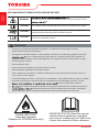 6
6
-
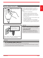 7
7
-
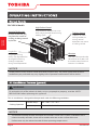 8
8
-
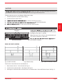 9
9
-
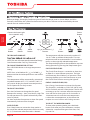 10
10
-
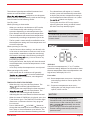 11
11
-
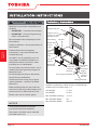 12
12
-
 13
13
-
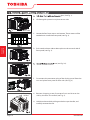 14
14
-
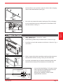 15
15
-
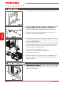 16
16
-
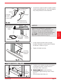 17
17
-
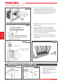 18
18
-
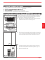 19
19
-
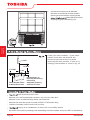 20
20
-
 21
21
-
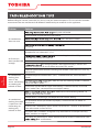 22
22
-
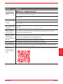 23
23
-
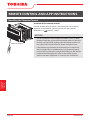 24
24
-
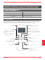 25
25
-
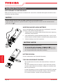 26
26
-
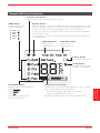 27
27
-
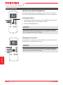 28
28
-
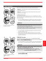 29
29
-
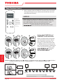 30
30
-
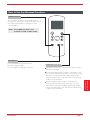 31
31
-
 32
32
-
 33
33
-
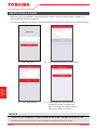 34
34
-
 35
35
-
 36
36
-
 37
37
-
 38
38
-
 39
39
-
 40
40
-
 41
41
-
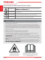 42
42
-
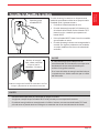 43
43
-
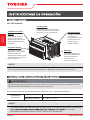 44
44
-
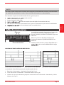 45
45
-
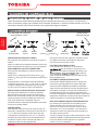 46
46
-
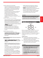 47
47
-
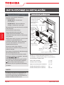 48
48
-
 49
49
-
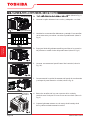 50
50
-
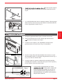 51
51
-
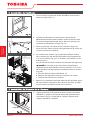 52
52
-
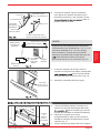 53
53
-
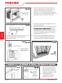 54
54
-
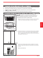 55
55
-
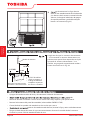 56
56
-
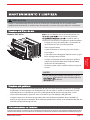 57
57
-
 58
58
-
 59
59
-
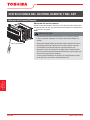 60
60
-
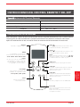 61
61
-
 62
62
-
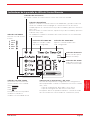 63
63
-
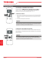 64
64
-
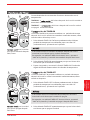 65
65
-
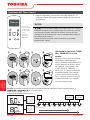 66
66
-
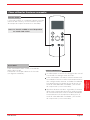 67
67
-
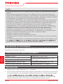 68
68
-
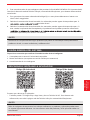 69
69
-
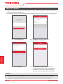 70
70
-
 71
71
-
 72
72


Toshiba RAC-WK1823ESCWR Guía del usuario
- Tipo
- Guía del usuario
en otros idiomas
- English: Toshiba RAC-WK1823ESCWR User guide