Brother Sewing Machine 2340CV Manual de usuario
- Categoría
- Máquinas de coser
- Tipo
- Manual de usuario
Este manual también es adecuado para

Cover Stitch Machine Operation Manual
Manual de instrucciones de la máquina de
puntada de recubierto
CONTENTS: ENGLISH
I. Names of parts and their functions ............. 3
II. Preparation before threading ..................... 8
III. Threading .................................................. 9
IV. Types of stitches ..................................... 11
Tri-cover stitch .............................................11
Two needle three threads cover stitch ........ 12
Chain stitch sewing..................................... 14
V. Sewing ..................................................... 15
VI. Maintenance ........................................... 19
VII. Machine specifications ..........................19
INDICE: ESPAÑOL
I. Nombres de las partes y sus funciones ....21
II. Preparación antes del enhebrado ............26
III. Enhebrado .............................................. 27
IV. Tipos de puntadas................................... 29
Puntada de recubierto triple ....................... 29
Puntada de recubierto de
dos agujas con tres hilos ................. 30
Costura de puntada de cadena .................. 32
V. Costura ....................................................33
VI. Mantenimiento ........................................37
VII. Especificaciones de la máquina ............ 37
ENGLISH
ESPAÑOL

"IMPORTANT SAFETY INSTRUCTIONS"
When using the sewing machine, basic safety precautions should always be followed,
including the following.
"Read all instructions before using."
DANGER – To reduce the risk of electric shock.
1. The sewing machine should never be left unattended when plugged in. Always unplug this sewing machine
from the electrical outlet immediately after using and before cleaning.
2. Always unplug before relamping. Replace bulb with same type rated 15 watts.
WARNING – To reduce the risk of burns, fire, electric shock, or injury to persons.
1. Do not allow to be used as a toy. Close attention is necessary when the sewing machine is used by or near
children.
2. Use this sewing machine only for its intended use as described in this manual. Use only accessories
recommended by the manufacturer as contained in this manual.
3. Never operate this sewing machine if it has a damaged cord or plug, if it is not working properly, if it has been
dropped or damaged, or dropped into water. Return the sewing machine to the nearest authorized dealer
or service center for examination, repair, electrical or mechanical adjustment.
4. Never operate the sewing machine with any air openings blocked. Keep ventilation openings of the sewing
machine and foot controller free from the accumulation of lint, dust, and loose cloth.
5. Never drop or insert any object into any openings.
6. Do not use outdoors.
7. Do not operate where aerosol (spray) products are being used or where oxygen is being administered.
8. To disconnect, turn the main switch to the symbol “O” position which represents off, then remove plug from
outlet.
9. Do not unplug by pulling on cord. To unplug, grasp the plug, not the cord.
10. Keep fingers away from all moving parts. Special care is required around the sewing machine needle.
11. Always use the proper needle plate. The wrong plate can cause the needle to break.
12. Do not use bent needles.
13. Do not pull or push fabric while stitching. It may deflect the needle causing it to break.
14. Switch the sewing machine to the symbol “O” position when making any adjustments in the needle area, such
as threading needle, changing needle, or changing presser foot, and the like.
15. Always unplug the sewing machine from the electrical outlet when removing covers, lubricating, or when
making any other user servicing adjustments mentioned in the instruction manual.
16. This sewing machine is not intended for use by young children or infirm persons without supervision.
17. Young children should be supervised to ensure that they do not play with this sewing machine.
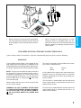
CAUTION – This appliance has a polarized plug (one blade wider than the other) to reduce the
risk of electric shock, this plug is intended to fit in a polarized outlet only one way.
If the plug does not fit fully in the outlet, reverse the plug.
If it still does not fit. Contact a qualified electrician to install the proper outlet.
Do not modify the plug in any way.
"SAVE THESE INSTRUCTIONS"
"This sewing machine is intended for household."

1
ENGLISH
FOR USERS IN THE UK, EIRE, MALTA AND CYPRUS ONLY.
If your sewing machine is fitted with a 3 pin non rewireable BS plug then please read the following.
IMPORTANT
If the available socket outlet is not suitable for the
plug supplied with this equipment, it should be cut off
and an appropriate three pin plug fitted. With alterna-
tive plugs an approved fuse must be fitted in the plug.
NOTE: The plug severed from the mains lead must
be destroyed as a plug with bared flexible cords is
hazardous if engaged in a live socket outlet. In the
event of replacing the plug fuse, use a fuse approved
by ASTA to BS 1362, i.e. carrying the
ASA
mark, rating
as marked on plug.
Always replace the fuse cover, never use plugs with
the fuse cover omitted.
WARNING: DO NOT CONNECT EITHER WIRE
TO THE EARTH TERMINAL WHICH IS MARKED
WITH THE LETTER ‘E’, BY THE EARTH SYMBOL
OR COLOURED GREEN OR GREEN AND
YELLOW.
The wires in this mains lead are coloured in accord-
ance with the following code:
Blue Neutral
Brown Live
As the colours of the wiring in the mains lead of this
appliance may not correspond with the coloured
markings identifying the terminals in your plug, pro-
ceed as follows.
The wire which is coloured blue must be connected
to the terminal which is marked with the letter ‘N’ or
coloured black or blue.
The wire which is coloured brown must be connected
to the terminal which is marked with the letter ‘L’ or
coloured red or brown.
• When leaving this sewing machine unattended,
the main switch of the machine must be switched
off or the plug must be removed from the socket-
outlet.
• When servicing the sewing machine, or when
removing covers or changing lamps, the ma-
chine or the electrical set must be disconnected
from the supply by removing the plug from the
socket-outlet.

2
CONGRATULATIONS ON
CHOOSING THIS COMPACT COVER STITCH MACHINE
Your machine is a high quality, easy-to-use product. To fully enjoy all the features, we suggest that
you study this booklet.
If you need more information regarding the use of your machine, your nearest authorized dealer is
always happy to be of service.
Enjoy yourself!
CAUTION!
WHEN THREADING, REPLACING NEEDLE OR LIGHT BULB, BE SURE TO TURN OFF THE MAIN
POWER SWITCH OF THE MACHINE.
WHEN THE MACHINE IS NOT IN USE, IT IS RECOMMENDED THAT THE ELECTRIC SUPPLY PLUG
IS DISCONNECTED FROM THE WALL SOCKET TO AVOID ANY POSSIBLE HAZARDS.
Notes on the motor
• The normal operating speed of this sewing machine is 1,000 stitches per minute, which is quite fast compared
to the normal operating speed of 300 to 800 stitches per minute for the ordinary foot-operated sewing machine.
• The bearings in the motor are made of a special sintered, oil-impregnated alloy mounted in oil-soaked felt to
withstand long hours of continuous operation.
• Continuous operation of the sewing machine can cause heat to build in the motor area, but not enough to
adversely affect its performance.
It is important to keep fabric and paper away from the ventilating holes on the back and sides of the machine
so air can get to these holes.
• When the motor is running, sparks can be seen through the ventilating hole in the motor bracket on the side
opposite the hand wheel. These sparks are produced by the carbon brushes and the commutator, and are
part of the machines normal operation.
CAUTION
WHEN THREADING THE MACHINE, REPLACING A NEEDLE, OR WHEN THE MACHINE IS NOT IN
USE, WE RECOMMEND DISCONNECTING THE ELECTRIC SUPPLY PLUG TO AVOID ANY POSSI-
BLE HAZARDS.

3
ENGLISH
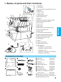
I. Names of parts and their functions
1 Thread tree
2 Thread plate
3 Presser foot pressure adjustment screw
4 Spool pin
5 Spool cushion
6 Spool support
7 Thread take-up cover
8 Material plate cover
9 Needles
0 Differential feed raito adjustment dial
A Stitch length adjustment dial
B Presser foot
C Front cover
D Hand wheel
E Main power switch and light switch
F Presser foot lifting lever
G Spool stand
H Left needle thread tension dial
I Center needle thread tension dial
J Right needle thread tension dial
K Looper thread tension dial
L Thread guide
M Looper
N Looper release lever
O Lopper thread take up
P Foot controller:
J01780051 (110/120V Area)
XA6406051 (220/240V Area)
XA6408051 (U.K.)
XA6410051 (Australia, New Zealand)
XA6420051 (Germany)
1 Soft cover X77871001
2 Accessory bag 122991002
3 Tweezers X75902001
4 Thread net (4) X75904000
5 Thread spool cap (4) X77260000
6 Spool mat (4) XB1218000
7 Cleaning brush X75906001
8 Hexagonal wrench XB0393001
9 Needle set: SCHMETZ 130/705H
(90/#14): 3pcs. XB1216001
0
Special presser foot (LC1)
XB1265001
The special presser foot is used when an
optional attachment is used.
Accessories included
P
1
2
3
4
5
6
7
8
9
0
F
E
A
0
1
C
2
3
4
5
6
8
7
9
B
O
M
N
G
H
I
D
K
J
L

4
Preparation
• Insert the three-pin plug into the socket on the bottom
right side of the machine. Insert the power supply plug
into a power outlet.
Main Power and Sewing Light Switch
This switch turns the power and sewing light on or off. To turn
on push toward “ – ” mark. To turn off push toward “ ” mark.
1 Main Power and Sewing Light Switch
Operation
When the pedal is pressed lightly, the machine runs at a
low speed. As the pedal is pressed further, the machine
will increase speed. When the pedal is released, the
machine stops.
2 Foot Controller: Model N
1
2
Powering the machine
• The motor and hand wheel of this machine turn in a
counterclockwise direction (direction of arrow). This is
the same direction as an ordinary home sewing ma-
chine.
1 Hand wheel
1
Turning direction of motor
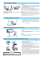
Opening and closing the front cover
It is necessary to open the front cover when threading this
machine.
• Open the front cover by sliding it to the right and
guiding the top toward you.
NOTE:
For your safety, make sure that the front cover is closed
when operating the machine.
• Turn off the main power switch or disconnect the
electric supply plug.
(1)Raise the presser foot lever. 1
(2)Set the needle to its highest position by turning the
hand wheel 2 counter clockwise.
(3)Push the button on the presser foot holder and the
standard foot will be released. 3 4
(4)Raise the presser foot farther by pushing the presser
foot lever upward. Then remove the presser foot and
store it in a safe location.
(5)Again, raise the presser foot farther by pushing the
presser foot lever upward. Then place a presser foot
just under the presser foot holder A so that the
groove in the bottom of the presser foot holder B is
aligned and catches the bar on the top of the foot C.
Then lower the presser foot lever to attach the foot.
How to attach and remove the presser foot
CAUTION
Always be sure to turn off the power before
carrying out this operation.
1
2
3
1
4
2
4
A
B
C
NOTE: (For U.S.A. only)
This foot controller can be used for sewing machine
model 2340CV.

5
ENGLISH
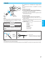
Stitch length
To change the stitch length,
(1)Locate the stitch length adjustment dial on the left side
of the machine.
(2)Turn the stitch length adjustment dial forward to
lengthen the stitch to a maximum of 4 mm (5/32 inch).
Turn the stitch length adjustment dial backwards to
shorten the stitch length to a minimum of 2 mm (5/64
inch).
(3)The normal stitch length setting is 3 mm to 4 mm
(1/8 to 5/32 inch)
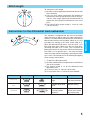
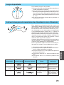
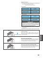
Instructions for the differential feed mechanism
This machine is equipped with two sets of feed dogs
under the presser foot to move the fabric through the
machine. The differential feed controls the movement of
both the front and the rear feed dogs. When set at 1, the
feed dogs are moving at the same speed (ratio of 1).
When the differential feed ratio is set at less than 1, the
front feed dogs move slower than the rear feed dogs,
stretching the fabric as it is sewn. This is effective on
lightweight fabric that may pucker. When the differential
feed ratio is set at greater than 1, the front feed dogs
move faster than the back feed dogs, gathering the fabric
as it is sewn. This function assists in removing the rippling
when serging stretch fabrics.
• To adjust the differential feed.
(1)Locate the differential feed adjustment lever on the left
side of the machine.
(2)The normal setting is 1.0 on the differential feed
adjustment lever.
(3)To set less than 1.0, move the lever back.
(4)To set greater than 1.0, move the lever forward.
Feed ratio Main feed (rear) Differential feed (front) Effect Application
0.7 – 1.0
1.0
1.0 – 2.0
Material is pulled
tight.
Without differential
feed.
Material is gath-
ered or pushed
together.
Prevents thin mate-
rials from puckering
Normal sewing
Prevents stretch ma-
terials from stretch-
ing or puckering
(3)
(4)

6
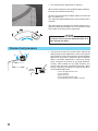
• An example where adjustment is required
When stretch material is sewn without using the differen-
tial feed, the material will be wavy.
To make the material more smooth, adjust the feed ratio
from 1.0 toward 2.0.
(The feed ratio required depends on the elasticity of the
material.)
The more elastic the material, the further toward 2.0 the
differential feed ratio should be set. Test sew with a scrap
of the fabric to find the correct adjustment.
CAUTION
When sewing thick non-stretchable material such
as denim, do not use the differential feed as it
may damage the fabric.
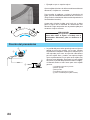
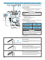
Presser foot pressure
1
2
3
• The pressure of the presser foot can be adjusted by
turning the pressure adjustment screw at the top left
of this machine. Since this machine has already been
adjusted to a pressure suitable for light to medium
fabrics, no further adjustment is necessary except
when sewing on very heavy or very light materials.
Usually, when sewing on very light materials, the
presser foot pressure should be loosened. When
sewing very heavy materials, the presser foot pres-
sure should be tightened.
1 Pressure adjustment screw
2 Less pressure
3 More pressure
4 Pressure adjustment screw
5 (Standard height for medium material)
4
10mm
(
3
/
8
inch)
5

7
ENGLISH
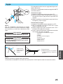
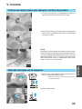
Needle
This machine uses a standard home sewing machine
needle.
The recommended needle is SCHMETZ 130/705H
(90/#14).
To remove the needle
(1)Turn the main power switch to the OFF position.
(2)Turn the hand wheel counter-clockwise by hand until
the needle is at its highest position.
(3)Loosen the needle set screw with hexagonal wrench
and remove the needle.
To insert the needle
(1)Turn the main power switch to the OFF position.
(2)Turn the hand wheel until the needle bar is at its
highest position.
(3)Hold the needle with its flat side away from you and
insert it up as far as it will go.
(4)Tighten the needle set screw securely with the hex-
agonal wrench.
1 Needle set screw
2 Tighten
3 Loosen
4 Hexagonal wrench
5 Window
6 Left needle
7 Center needle
8 Right needle
5
1
4
67 8
2
3
NOTE:
When front needles are inserted correctly you can
see the top of the needle in the window (5) above
each needle position.
CAUTION
Always be sure to turn off the power before
carrying out this operation.
CAUTION
Do not drop the needle and needle set screw
in the machine, otherwise it may be dam-
aged.
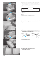
Needle description
1
2
3
4
5
6
How to check the needle
1 Back
2 Front
3 Flat side
4 Groove
5 Flat surface
6 Place the needle on its flat side and
check to see if the space is parallel.
NOTE:
Countermeasures for material breakage.
It can reduce the occurrence of material breakage by using SCHIMETZ 130/705H SUK (90/#14) BALL POINT.

8
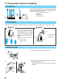
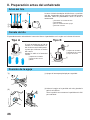
II. Preparation before threading
4
1
2
3
Raise the telescoping thread tree to its highest position.
Make sure that the thread holders are in alignment above
the spool pins as illustrated left.
1 Thread holder on thread tree
2 Spool pin
3 Spool cushion
4 Correct position
Thread spool
The procedure for placing the spool of thread on the spool pin differs according to the shape of the spool.
3
If you are sewing with loosely
spun nylon thread, we recom-
mend that you cover the spool
with the net supplied to prevent
the thread from slipping off the
spool.
Adapt the net to the shape of the
spool.
1 Spool support
2 Spool cushion
3 Net
1 Spool support
2 Spool mat
3 Spool cap
Type A Type B
Thread tree
1
2
1
2
3
(1)
(2)
(1)Turn off the main power switch for safety.
Needle position
(2)Set the needle bar in its highest position by turning the
handwheel toward you.
Turn the handwheel to find the easiest position for
threading.

9
ENGLISH
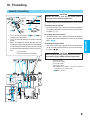
III. Threading
Needle threading
1
2
3
1
2
3
1
2
3
666
4 4 4
5 5 5
A
B
C
D
7
888
999
77
6
4
5
E
333
333
444
F
G
CAUTION
Always be sure to turn off the power before
carrying out the following operation.
(1) Follow the procedure described below to thread the needle.
Threading the left needle
• Run the thread in the sequence illustrated, following
the yellow color and the numbers next to each thread-
ing point. (1-9)
Threading the center needle
• Run the thread in the sequence illustrated, following
the pink color and the numbers next to each threading
point. (1-9)
Threading the right needle
• Run the thread in the sequence illustrated, following
the green color and the numbers next to each thread-
ing point. (1-9)
CAUTION
When needle threading, always thread in this order:
Left needle, center needle and then right needle.
A To left needle
B To center needle
C To right needle
D Branching plate
E Pull about 6 cm (about 2-1/2 inches) of thread
through the eye of the needle.
999 Front to back
• Pass each thread from 333 to 444 as
shown in this illustration.
• Pass the thread through the proper thread
guide.
• Slide and hold the thread tension release
button to the right, then pass the thread through
the tension disc which is in the channel next to
the tension adjustment dial. Release the but-
ton.
F Tension disk
G Thread tension release button

10
1
2
4
5
6
7
8
9
6
4
5
3
4
3
0
B
C
D
A
A
B
3
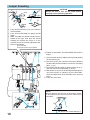
CAUTION
Always be sure to turn off the power before
carrying out the following operation.
Looper threading
A
NOTE:
When using thick thread, such as decorative thread,
as the looper thread, run the thread as shown in the
illustration.
• Pass each thread from 3 to 4 as shown in
this illustration.
• Pass the thread through the proper thread
guide.
• Slide and hold the thread tension release
button to the right, then pass the thread
through the tension disc which is in the
channel next to the tension adjustment dial.
Release the button.
A Tension disk
B Thread tension release button
(1)Follow the procedure described below to thread the
looper.
1 Open the front cover by sliding to the right and guiding
the top toward you.
2 Run the thread in the sequence illustrated, following
the blue color and the numbers next to each threading
point. (1-0)
3 After running the thread to 0, pull the release lever A,
and then run the thread through B and C.
4 With about 10 cm (4 inch) of thread pulled through the
eye of the needle, as shown by D in the illustration,
move the looper back in the direction of the arrow to
lock it.
5 Close the front cover.
Do not run the thread through A.

11
ENGLISH
IV. Types of stitches
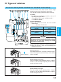
Tri-cover stitch (Three needles four threads cover stitch)
Use four threads, three front needles and the looper
thread to sew a 6 mm (15/64 inch) cover stitch.
Use: Ideal for hemming and for decorative stitching.
Threading
• For details on threading the machine, refer to “III.
Threading” on page 9 to 10.
< Threading the left, center and right needle >
< Threading the looper >
Tension adjustments
(1)First, set each thread tension dial to the number
shown below.
A Tension selection mark
Stitching direction
Balanced tension
The needle thread sews a straight seam on the top
side and the looper thread forms loops on the under
side of the fabric.
Needle thread is too loose
Turn the needle thread adjusting dial to a higher
number. Or turn the looper adjusting dial to a lower
number for looser tension.
Needle thread is too tight
Turn the needle thread adjusting dial to a lower
number. Or turn the looper adjusting dial to a higher
number for tighter tension.
Left needle dial
(yellow)
4
Center needle dial
(pink)
4
Looper needle dial
(blue)
4
Right needle dial
(green)
4
A
CAUTION
Make sure that the thread is properly seated in
the tension discs by holding the tension release
button to the right while passing the thread
through the tension discs.
(2)Sew a test stitch. (Refer to “V. Sewing” on page 15.)
(3)Adjust the tension of each thread according to the
condition of the stitch.

12
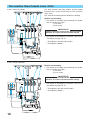
Two needles three threads cover stitch
Use three threads, two front needles and the looper
thread to sew a 6 mm (15/64 inch) or 3 mm (1/8 inch)
cover stitch.
Use: Ideal for hemming and for decorative stitching.
Needles and threading
• For details on installing and removing the needle,
refer to “Needle” on page 7.
1 Left needle
2 Right needle
IMPORTANT!!
Lightly tighten the screw at the unused needle
position, so it does not fall out while sewing.
• For details on threading the machine, refer to “III.
Threading” on page 9 to 10.
< Threading the left and right needle >
< Threading the looper >
6 mm (15/64 inch) (Wide)
3 mm (1/8 inch) (Narrow)
1 2
A
3 4
A
Needles and threading
• For details on installing and removing the needle,
refer to “Needle” on page 7.
3 Left needle
4 Center needle
IMPORTANT!!
Lightly tighten the screw at the unused needle
position, so it does not fall out while sewing.
• For details on threading the machine, refer to “III.
Threading” on page 9 to 10.
< Threading the left and center needle >
< Threading the looper >

13
ENGLISH
Tension adjustments
(1)First, set each thread tension dial to the number
shown below.
A Tension selection mark
6 mm (15/64 inch) (Wide)
Balanced tension
The needle thread sews a straight seam on the top
side and the looper thread forms loops on the under
side of the fabric.
Needle thread is too loose
Turn the needle thread adjusting dial to a higher
number. Or turn the looper adjusting dial to a lower
number for looser tension.
Needle thread is too tight
Turn the needle thread adjusting dial to a lower
number. Or turn the looper adjusting dial to a higher
number for tighter tension.
Stitching direction
Left needle dial
(yellow)
4
Center needle dial
(pink)
–
Looper needle dial
(blue)
4
Right needle dial
(green)
4
CAUTION
Make sure that the thread is properly seated in
the tension discs by holding the tension release
button to the right while passing the thread
through the tension discs.
(2)Sew a test stitch. (Refer to “V. Sewing” on page 15.)
(3)Adjust the tension of each thread according to the
condition of the stitch.
3 mm (1/8 inch) (Narrow)
Left needle dial
(yellow)
4
Center needle dial
(pink)
4
Looper needle dial
(blue)
4
Right needle dial
(green)
–

14
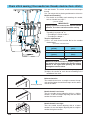
Chain stitch sewing (One needle two threads double chain stitch)
Use two threads. The center needle thread and looper
thread.
Use:
For straight stitching, basting and decorative chain stitch.
Needle and threading
• For details on installing and removing the needle,
refer to “Needle” on page 7.
1 Center needle
IMPORTANT!!
Lightly tighten the screw at the unused needle
position, so it does not fall out while sewing.
• For details on threading the machine, refer to “III.
Threading” on page 9 to 10.
< Threading the center needle >
< Threading the looper >
Tension adjustments
(1)First, set each thread tension dial to the number
shown below.
A Tension selection mark
Balanced tension
The needle thread sews a straight seam on the top
side and the looper thread forms loops on the under
side of the fabric.
CAUTION
Make sure that the thread is properly seated in
the tension discs by holding the tension release
button to the right while passing the thread
through the tension discs.
(2)Sew a test stitch. (Refer to “V. Sewing” on page 15.)
(3)Adjust the tension of each thread according to the
condition of the stitch.
Stitching direction
Left needle dial
(yellow)
–
Center needle dial
(pink)
2
Looper needle dial
(blue)
5
Right needle dial
(green)
–
1
A
Needle thread is too loose
Turn the needle thread adjusting dial to a higher
number. Or turn the looper adjusting dial to a lower
number for looser tension.
Needle thread is too tight
Turn the needle thread adjusting dial to a lower
number. Or turn the looper adjusting dial to a higher
number for tighter tension.

15
ENGLISH
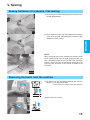
V. Sewing
Sewing flat fabric (for example, trial sewing)
(1)Raise the presser foot, and then place the fabric at the
needle drop position.
A
Removing the fabric from the machine
(2)Raise the presser foot.
NOTE:
When starting to sew or after changing the thread, in order
for the needle thread to be on top of the presser foot, sew
with it positioned under the presser foot when you begin
sewing. If necessary, turn the handwheel toward you a few
times by hand, and then cut the thread as shown in the
illustration.
(1)By hand, turn the handwheel toward you until the
needle is at its highest position.
A
This is where the needle is at its highest position.
(2)
Lower the presser foot, turn the handwheel toward you
a few times by hand, and then lightly step on the foot
controller to start sewing.
(1)
(2)
NOTE
(1)
(2)

16
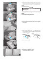
(3)While firmly taking the fabric with your hand, push the
thread release button to the right for the needle thread
currently being used to open the thread tension disc.
NOTE:
Do not take the seam.
CAUTION
Be careful when taking the fabric since the light
bulb is very hot.
(4)
Slowly pull the fabric in the direction of the arrow with (3).
NOTE:
Be sure to pull the fabric to the back.
(5)Cut the needle thread which comes out on the upside
of the fabric.
(6)Again, slowly pull the fabric in the direction of the
arrow, so that the end of the needle threads are pulled
out behind the fabric.
(7)Cut the looper thread.
(8)All threads are pulled at the back.
Tie all threads together and cut.
(3)
(4)
(5)
(6)
(7)
(8)

17
ENGLISH
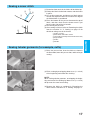
Sewing tubular garments (for example, cuffs)
(1)Raise the presser foot, insert the fabric as shown in
the illustration, lower the presser foot, and then begin
sewing.
(2)Finish sewing by overlapping about 4 cm (1-1/2 inch)
of the beginning and end of the stitching.
NOTE:
When sewing tubular garments, overlapping the begin-
ning and end of the stitching by about 4 cm (1-1/2 inch)
will prevent the seam from tearing.
(3)Remove the fabric as explained in “Removing the
fabric from the machine” in “V. Sewing” on page 15.
Sewing a cover stitch
(1)Determine how much of the fabric will be folded up.
(2)Fold up the fabric the desired amount, and then iron it
in place.
(3)Use a ruler to measure, and then use a fabric marker
to mark the top of the fabric to see where the edge of
the folded fabric is positioned.
(4)Place the bottom of the presser foot onto the top of
fabric, and then check that the drawn mark is just
barely to the right of the left needle.
(5)Sew exactly on the mark.
(6)After sewing is finished, refer to “Removing the fabric
from the machine” in “V. Sewing” on page 15 for
details on taking care of the thread.
1 Fabric (surface)
2 Mark drawn with fabric marker
3
Left needle (just barely on the left side of the mark)
4 Right needle
5 Fabric
6 Needle
1
3
2
4
6
5
(1)
(2)

18
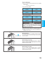
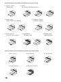
Actual examples of two needles three threads cover stitch sewing
1) Hems of T-shirts
(Simple stitch)
Actual examples of three-needles four-threads cover stitch sewing
1) Plain stitching 2) Hem stitching 3) Tape attaching
4) Circular hemming 5) Elastic lace attaching
2) Stitches
(Top stitched seams/Ribbing/Yokes)
3) Attaching tape
(edges of collars, etc) (Binding)
4) Decorative stitching
(Decorative stitching)
5) Attaching elastic
(Hem with sewn-in elastic)
6) Attaching lace
(Flat joining seam)
7) Belt loop sewing
(Belt loop sewing)

19
ENGLISH
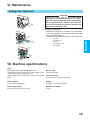
VI. Maintenance
Change the light bulb
1
2
3
4
4
5
CAUTION
Always be sure to turn off the power before
carrying out the following operation. The glass
plate over the light bulb will be hot immediately
after using the machine, therefore it is advisable
to wait until the light bulb has had a chance to cool
down before changing bulbs.
Changing the light bulb.
• Remove the lamp cover as shown in the illustration.
• Loosen the lightbulb cover set screw pull up the light
bulb cover and remove it.
• Take out the light bulb and replace it with a new one.
1 Screw
2 Lamp cover
3 Screw
4 Light bulb cover
5 Light bulb
VII. Machine specifications
Stitch
One needle two thread double chain stitch
Two needles three thread cover stitch (Wide 6 mm
(15/64 inch)/Narrow 3 mm(1/8 inch))
Three needles four thread cover stitch (6 mm (15/64
inch))
Sewing speed
1,000 stitches per minute
Stitch length (pitch)
2 mm to 4 mm (5/64 to 5/32 inch)
Presser foot
Free presser type
Presser foot lift
5 mm to 6 mm (3/16 to 15/64 inch)
Needle
SCHMETZ 130/705H (90/#14)
Machine net weight
7.0 kgs.

20
FELICITACIONES POR HABER ELEGIDO ESTA
COMPACTA MÁQUINA DE PUNTADA DE RECUBIERTO
Su máquina es de una eficacia y calidad excelentes; así pues, a fin de disfrutar completamente de
todas las características incorporadas, le sugerimo estudie el manual.
Si se necesitara mayor información sobre el uso de esta máquina, el proveedor autorizado más
cercano estará encantado de ofrecerle sus servicios.
¡PRECAUCIÓN!
ASEGURARSE DE QUE EL INTERRUPTOR GENERAL DE LA MAQUINA ESTE APAGADO CUANDO SE
ENHEBRE, REEMPLACE LA AGUJA O CAMBIE LA LAMPARITA.
CUANDO NO SE UTILICE LA MAQUINA, SE RECOMIENDA QUE EL ENCHUFE ESTE DESCONECTA-
DO DE LA RED DE LA CORRIENTE, A FIN DE EVITAR CUALQUIER PELIGRO.
NOTAS SOBRE EL MOTOR
• La velocidad normal de funcionamiento de esta máquina de coser es de 1.000 puntadas por minuto, lo que
resulta bastante rápido comparado con la velocidad normal de 300 a 800 puntadas por minuto de las
máquinas de coser normales que funcionan con pedal.
• Los cojinetes del motor están hechos de una aleación especial impregnada en aceite sintético y montada en
un fieltro impregnado en aceite, para poder funcionar continuamente durante muchas horas.
• Un funcionamiento continuo de la máquina puede contribuir a calentar algo la máquina en la zona del motor,
pero no lo suficiente como para alterar su rendimiento y funcionamiento.
Sin embargo, es menester mantener los orificios de ventilación de la parte trasera y en los lados de la máquina
sin tapar con tejido o papel durante el uso, para que el aire pueda circular por los orificios.
• Durante el funcionamiento del motor, se pueden ver chispas a través del orificio de ventilación de la
abrazadera del motor, en el lado contrario a la ruedecilla. Estas chispas son producidas por las escobillas
de carbón que entran en contacto con el conmutador, y forman parte del funcionamiento normal de la
máquina.
PRECAUCIÓN
Al enhebrar la máquina, cambiar una aguja o al dejar la máquina sin usar, le recomendamos
desenchufar la máquina para evitar cualquier peligro de corto circuito.

21
ESPAÑOL
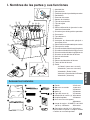
I. Nombres de las partes y sus funciones
1 Arbol del hilo
2 Placa del hilo
3
Tornillo de ajuste de la presión del prensatelas
4 Portabobina
5 Protector del carrete
6 Soporte de la bobina
7 Tapa de toma de hilo
8 Tapa de tejido
9 Agujas
0 Palanca diferencial de ajuste de la velo-
cidad de alimentación
A Disco de ajuste del largo de las puntadas
B Prensatelas
C Tapa delantera
D Ruedecilla
E Interruptor de alimentación principal e
interruptor de luz
F Palanca de levantamiento del prensatelas
G Filete para la canilla
H
Disco de tensión del hilo de la aguja izquierda
I
Disco de tensión del hilo de la aguja central
J
Disco de tensión del hilo de la aguja derecha
K Disco de tensión del hilo del áncora
L Guía de enhebrado
M Áncora
N Palanca de liberación del áncora
O Toma de hilo del áncora
P Pedal:
J01780051 (zona con 110/120V)
XA6406051 (zona con 220/240V)
XA6408051 (Reino Unido)
XA6410051 (Australia, Nueva Zelanda)
XA6420051 (Alemania)
1 Funda X77871001
2 Bolsa de accesorios 122991002
3 Pinzas X75902001
4 Malla (4) X75904000
5 Tope del carrete (4) X77260000
6
Alfombrilla del carrete
(4) XB1218000
7 Cepillo limpiador X75906001
8 Llave de tuerca hexagonal
XB0393001
9 Juego de agujas: SCHMETZ 130/705M
(90/#14): 3 unidades XB1216001
0
Prensatelas especial
(LC1)
XB1265001
El prensatelas especial se emplea cuando
se utiliza un accesorio opcional.
Accesorios incluidos
P
1
2
3
4
5
6
7
8
9
0
F
E
A
0
1
C
2
3
4
5
6
8
7
9
B
O
M
N
G
H
I
D
K
J
L

22
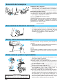
Preparación de la máquina
•
Introduzca el zócalo de tres puntas en el enchufe que se
encuentra abajo, en el lado derecho de la máquina e
inserte el zócalo de alimentación en una toma de corriente.
Interruptor principal y de luz
Este interruptor permite apagar y encender la máquina
así como la luz. Para encender, empuje hacia la marca
“–”; para apagar, póngalo en la marca “”.
1 Interruptor principal y de luz
Funcionamiento
Al oprimir ligeramente el pedal, la máquina funcionará a
baja velocidad. A medida que se apriete más, la máquina
incrementará su velocidad. La máquina se parará tan
pronto como se suelte el pedal.
2 Pedal: Model N
1
2
Encendido de la máquina
• El motor y la ruedecilla de esta máquina funcionan en
el sentido contrario al de las manecillas del reloj
(dirección de la flecha), como es el caso con la
mayoría de las máquinas de coser domésticas.
1 Ruedecilla
1
Para cambiar la dirección del motor
Abre y cierre de la tapa delantera
Es necesario abrir la tapa delantera para enhebrar la
máquina.
• Abra la tapa delantera moviéndola hacia la derecha y
dirigiendo la parte superior hacia usted.
NOTA:
Para su propia seguridad, averigue siempre que la tapa
delantera esté bien cerrada antes de hacer funcionar la
máquina.
• Apague el interruptor principal o desconecte el en-
chufe de la toma de corriente.
(1)Levante la palanca del prensatelas. 1
(2)Ponga la aguja en su posición más alta, girando la
ruedecilla 2 con la mano en el sentido contrario al de
las manecillas de un reloj.
(3)Apriete el botón en el eje del prensatelas, lo que
liberará el prensatelas colocado. 3 4
(4)Levante aún más el prensatelas al apretar la palanca
correspondiente hacia arriba. Luego, retire el
prensatelas y guárdelo en un lugar seguro.
(5)Otra vez, levante aún más el prensatelas presionan-
do la palanca del prensatelas hacia arriba. A conti-
nuación, coloque el prensatelas justo debajo del eje
del prensatelas A a fin de que la ranura que se
encuentra abajo del eje B se alinee y enganche la
barra en la parte superior del prensatelas C. Luego
baje la palanca del prensatelas para sujetarlo.
Cómo colocar y retirar el prensatelas
PRECAUCIÓN
Asegúrese siempre de desconectar la ali-
mentación antes de realizar esta operación.
1
2
3
1
4
2
4
A
B
C

23
ESPAÑOL
Largo de puntada
Para cambiar el largo de las puntada:
(1)Busque el disco de ajuste del largo de las puntadas en
al lado izquierdo de la máquina.
(2)
Gire el disco de ajuste del largo de las puntadas hacia
adelante para alargar la puntada a un máximo de 4 mm.
Gire el disco de ajuste del largo de las puntadas hacia
atrás para acortar la longitud de puntada a un mínimo
de 2 mm.
(3)Un ajuste normal para el largo de las puntadas se
sitúa entre 3 y 4 mm.
Instrucciones para el mecanismo de alimentación con diferencial
Esta máquina está provista de dos series de
alimentadores debajo del prensatelas para guiar el tejido
por la máquina. El alimentador con diferencial controla
los movimientos de los alimentadores delanteros y trase-
ros. Al ajustarlo en 1, los alimentadores se desplazarán
a una velocidad idéntica (relación de 1). Al ajustar la
relación del alimentador con diferencial en menos de 1,
los alimentadores delanteros van a moverse más despa-
cio que los traseros, estirando el tejido a medida que se
cuese. Esta operación resulta muy eficiente al coser
materiales finos que pueden arrugarse.
Cuando el alimentador con diferencial esté ajustado en
un valor superior a 1, los alimentadores delanteros van
a moverse más rápido que los alimentadores
traseros, juntando el tejido al coserlo. Esta función per-
mite quitar las arrugas al coser tejidos que se estiran.
• Para ajustar el alimentador diferencial.
(1)Busque la palanca de ajuste del alimentador diferen-
cial en al lado izquierdo de la máquina.
(2)El ajuste normal es de 1,0 en la palanca de ajuste del
alimentador diferencial.
(3)Para ajustar menos de 1,0, mueva la palanca hacia
atrás.
(4)Para ajustar más de 1,0, mueva la palanca hacia
adelante.
0,7 – 1,0
1,0
1,0 – 2,0
(3)
(4)
Efecto
Velocidad de
alimentación
Alimentador
principal (detrás)
Alimentador con
diferencial (delante)
Aplicación
Impide que los teji-
dos finos frunzan.
Costura normal.
Impide que los teji-
dos extensibles se
estiren o frunzan.
El tejido se estira
Sin alimentación con
diferencial.
El tejido se contrae
o se junta.

24
• Ejemplo en que se requiere ajuste
Al coser tejidos elásticos sin utilizar una alimentación con
diferencial, el tejido va a ser oleado.
Para remediar el problema y mejorar la apariencia del
tejido, ajuste la velocidad de alimentación de 1,0 hacia 2,0.
(El ajuste de la velocidad de alimentación depende de la
elasticidad del material.)
Cuanto más elástico el tejido, más hacia 2,0 se debe
poner el ajuste de la velocidad de alimentación con
diferencial. Haga una prueba con un poco de tejido para
encontrar el ajuste correcto.
PRECAUCIÓN
Si debe coser tejidos gruesos que no son elás-
ticos, tales como el tejano, no trabaje con el
alimentador diferencial, para no deteriorar el
material.
Presión del prensatelas
1
2
3
• La presión del prensatelas puede ajustarse al girar el
tornillo de ajuste de presión, en la parte superior
izquierda de la máquina. Dado que la máquina ya ha
sido ajustada para tener una presión conveniente
para los tejidos finos y medios, no requiere ningún
ajuste suplementario si no es para coser tejidos muy
gruesos o muy delgados. En general, al coser tejidos
muy finos, la presión del prensatelas debe ser floja y,
al contrario, debe ser más fuerte para coser tejidos
gruesos.
1 Tornillo de ajuste de la presión
2 Menos presión
3 Más presión
4 Tornillo de ajuste de la presión
5 (altura estandard para tejidos medios)
4
10mm
5

25
ESPAÑOL
Aguja
Está máquina funciona con una aguja normal para má-
quinas domésticas.
Así mismo, se recomienda el uso de una aguja SCHMETZ
130/705H (90/#14).
Para sacar la aguja
(1)Apague el interruptor principal (posición OFF).
(2)Gire la ruedecilla a mano, en contra de las manecillas
del reloj hasta que la aguja alcance la posición más
elevada.
(3)Afloje el tornillo de instalación de la aguja con la llave
hexagonal y saque la aguja.
Para introducir la aguja
(1)Apague el interruptor principal (póngalo en OFF).
(2)Gire la ruedecilla hasta que la barra de la aguja
alcance la posición más alta.
(3)Sujete la aguja con la parte curvada de cara a Vd. e
insértela hacia arriba hasta el tope.
(4)Vuelva a apretar firmemente el tornillo de instalación
de la aguja con la llave hexagonal.
1 Tornillo de instalación de las agujas
2 Apretar
3 Aflojar
4 Llave de tuerca hexagonal
5 Ventana
6 Aguja izquierda
7 Aguja central
8 Aguja derecha
5
1
4
67 8
2
3
NOTA:
Una vez introducidas correctamente las agujas
delanteras, puede ver la parte superior de la aguja
en la ventana (5) encima de la posición de cada
aguja.
PRECAUCIÓN
Asegúrese siempre de desconectar la ali-
mentación antes de realizar esta operación.
PRECAUCIÓN
No deje caer la aguja y el tornillo de instala-
ción de la aguja en la máquina; de lo contra-
rio, podría dañarse.
Descripción de la aguja
1
2
3
4
5
6
Cómo comprobar la aguja
1 Parte trasera
2 Parte delantera
3 Parte llana
4 Canal
5 Superficie plana
6 Coloque la aguja en su parte llana
y compruebe que el espacio sea
paralelo.
NOTA:
Medidas preventivas contra la rotura de material.
La utilización de SCHIMETZ 130/705H SUK (90/#14) BALL POINT permite reducir la rotura de material.

26
II. Preparación antes del enhebrado
4
1
2
3
Levante el árbol telescópico del hilo hasta su posición
más alta. Compruebe que los corchetes de hilos quedan
alineados sobre los portabobinas como se ilustra a
continuación.
1 Portahilos en el árbol del hilo
2 Portabobina
3 En los modelos de dos agujas
4 Posición correcta
Carrete de hilo
El procedimiento de colocación del carrete de hilo en el portabobina varía según sea la forma del carrete.
3
Si está cosiendo con un hilo de
hilvanar, le recomendamos cu-
brir el carrete con la malla provis-
ta para que el hilo no se deslice
del carrete.
Adapte la malla a la forma del
carrete.
1 Soporte de la bobina
2 Protector del carrete
3 Malla
1 Soporte de la bobina
2 Alfombrilla del carrete
3 Tope del carrete
Tipo A Tipo B
Arbol del hilo
1
2
1
2
3
(1)
(2)
(1)Apagar el interruptor principal por seguridad.
Posición de la aguja
(2)Colocar la aguja en la posición más alta, girando la
polea hacia afuera.
Girar la perilla hasta encontrar la posición más fácil
para enhebrar.

27
ESPAÑOL
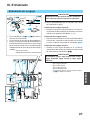
III. Enhebrado
Enhebrado de la aguja
1
2
3
1
2
3
1
2
3
666
4 4 4
5 5 5
A
B
C
D
7
888
999
77
6
4
5
E
333
333
444
F
G
PRECAUCIÓN
Asegúrese siempre de desconectar la alimenta-
ción antes de realizar la operación siguiente.
(1)Siga el procedimiento que se describe más abajo
para enhebrar la aguja.
Enhebrado de la aguja izquierda
• Enhebre la aguja tal como ilustrado en la secuencia,
respetando el color amarillo y los números inscritos al
lado de cada punto de enhebrado. (1-9)
Enhebrado de la aguja central
•
Enhebre el hilo teniendo en cuenta el orden indicado en
la ilustración, siguiendo el color rosado y los números
inscritos al lado de cada punto de enhebrado.
(1-9)
Enhebrado de la aguja derecha
• Enhebre el hilo según ilustrado en la secuencia,
siguiendo el color verde y los números inscritos al lado
de cada punto de enhebrado. (1-9)
PRECAUCIÓN
Al enhebrar agujas, siga siempre este orden:
aguja izquierda, aguja central y luego aguja
derecha.
A A la aguja izquierda
B A la aguja central
C A la aguja derecha
D Placa de bifurcación
E Tire del hilo unos 6 cm por el ojo de la aguja
999 De delante hacia atrás
• Pase cada hilo de 333 a 444 tal como se
muestra en la ilustración.
•
Pase el hilo por la guía de hilo correspondiente.
• Deslice y retenga el botón de liberación de la
tensión del hilo hacia la derecha y pase el hilo
por el disco de tensión, que es el canal situado
al lado del disco de ajuste de la tensión. Suelte
el botón.
F Disco de tensión
G
Botón de liberación de la tensión del hilo

28
1
2
4
5
6
7
8
9
6
4
5
3
4
3
0
B
C
D
A
A
B
3
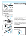
PRECAUCIÓN
Asegúrese siempre de desconectar la alimenta-
ción antes de realizar la operación siguiente.
Enhebrado del áncora
A
NOTA:
Al utilizar hilos gruesos (por ejemplo, hilos decorati-
vos) como hilos del áncora, enhebre el hilo según se
muestra en la ilustración.
• Pase cada hilo de 3 a 4 tal como se
muestra en la ilustración.
•
Pase el hilo por la guía de hilo correspondiente.
• Deslice y retenga el botón de liberación de la
tensión del hilo hacia la derecha y pase el
hilo por el disco de tensión, que es el canal
situado al lado del disco de ajuste de la
tensión. Suelte el botón.
A Disco de tensión
B
Botón de liberación de la tensión del hilo
(1)Siga el procedimiento que se describe más abajo
para enhebrar el áncora.
1 Abra la tapa delantera deslizándola hacia la derecha
y guiando la parte superior hacia usted.
2 Enhebre el hilo según lo ilustrado en la secuencia,
observando el color azul y los números inscritos al
lado de cada punto de enhebrado. (1-0)
3 Después de enhebrar la aguja a 0, tire de la palanca
de liberación A y, a continuación, enhebre el hilo por
B y C.
4 Pasando unos 10 cm de hilo por el ojo de la aguja,
según se muestra en la ilustración D, mueva el
áncora hacia atrás en la dirección de la flecha para
cerrarlo.
5 Cierre la tapa delantera.
No enhebre el hilo por A

29
ESPAÑOL
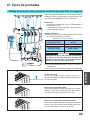
IV. Tipos de puntadas
Puntada de recubierto triple (puntada de recubierto de cuatro hilos y tres agujas)
Utilice tres agujas delanteras con cuatro hilos y el hilo del
áncora para coser una puntada de recubierto de 6 mm.
Uso: ideal para dobladillos y costura decorativa.
Enhebrado
• Si desea más información, véase “III. Enhebrado” en
las páginas 27 y 28.
<
Enhebrado de la aguja izquierda, central y derecha
>
< Enhebrado del áncora >
Ajustes de tensión
(1)En primer lugar, ajuste cada disco de tensión del hilo
en el número indicado más abajo.
A Marca de selección de tención
Dirección de la puntada
Tensión ajustada
El hilo de la aguja realiza costuras rectas en el
derecho del tejido y el hilo del áncora forma ondas en
el revés del tejido.
El hilo de la aguja está suelto
Gire el disco de ajuste del hilo de la aguja a un número
superior. O bien, gire el disco de ajuste del áncora a
un número inferior para disminuir la tensión.
El hilo de la aguja está demasiado tendido
Gire el disco de ajuste del hilo de la aguja a un número
inferior. O bien, gire el disco de ajuste del áncora a un
número superior para aumentar la tensión.
Disco de la aguja
izquierda (amarillo)
4
Disco de la aguja central
(rosado)
4
Disco de la aguja del
áncora (azul)
4
Disco de la aguja
derecha (verde)
4
A
PRECAUCIÓN
Asegúrese de que el hilo esté bien colocado en
los discos de tensión reteniendo el botón de
liberación de la tensión a la derecha mientras
pasa el hilo por los discos de tensión.
(2)Cosa una puntada de prueba. (Véase “V. Costura” en
la página 33.)
(3)
Ajuste la tensión de cada hilo según el tipo de puntada.

30
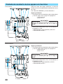
Puntada de recubierto de dos agujas con tres hilos
Utilice tres hilos, dos agujas delanteras y el hilo del
áncora para coser una puntada de recubierto de 6 mm o
de 3 mm.
Uso: ideal para dobladillos y costura decorativa.
Agujas y enhebrado
• Para información más detallada sobre cómo colocar
y sacar la aguja, véase “Aguja” en la página 25.
1 Aguja izquierda
2 Aguja derecha
IMPORTANTE!!
Apriete ligeramente el tornillo en la posición de
la aguja no utilizada para que no se caiga al
coser.
• Si desea más información, véase “III. Enhebrado” en
las páginas 27 y 28.
< Enhebrado de la aguja izquierda y derecha >
< Enhebrado del áncora >
6 mm (Ancha)
3 mm (Estrecha)
1 2
A
3 4
A
Agujas y enhebrado
• Para información más detallada sobre cómo colocar
y sacar la aguja, véase “Aguja” en la página 25.
3 Aguja izquierda
4 Aguja central
IMPORTANTE!!
Apriete ligeramente el tornillo en la posición de
la aguja no utilizada para que no se caiga al
coser.
• Si desea más información, véase “III. Enhebrado” en
las páginas 27 y 28.
< Enhebrado de la aguja izquierda y central >
< Enhebrado del áncora >

31
ESPAÑOL
Ajustes de tensión
(1)En primer lugar, ajuste cada disco de tensión del hilo
en el número indicado más abajo.
A Marca de selección de tención
6 mm (Ancha)
Tensión ajustada
El hilo de la aguja realiza costuras rectas en el
derecho del tejido y el hilo del áncora forma ondas en
el revés del tejido.
El hilo de la aguja está suelto
Gire el disco de ajuste del hilo de la aguja a un número
superior. O bien, gire el disco de ajuste del áncora a
un número inferior para disminuir la tensión.
El hilo de la aguja está demasiado tendido
Gire el disco de ajuste del hilo de la aguja a un número
inferior. O bien, gire el disco de ajuste del áncora a un
número superior para aumentar la tensión.
Dirección de la puntada
Disco de la aguja
izquierda (amarillo)
4
Disco de la aguja central
(rosado)
–
Disco de la aguja del
áncora (azul)
4
Disco de la aguja
derecha (verde)
4
PRECAUCIÓN
Asegúrese de que el hilo esté bien colocado en
los discos de tensión reteniendo el botón de
liberación de la tensión a la derecha mientras
pasa el hilo por los discos de tensión.
(2)Cosa una puntada de prueba. (Véase “V. Costura” en
la página 33.)
(3)
Ajuste la tensión de cada hilo según el tipo de puntada.
3 mm (Estrecha)
Disco de la aguja
izquierda (amarillo)
4
Disco de la aguja central
(rosado)
4
Disco de la aguja del
áncora (azul)
4
Disco de la aguja
derecha (verde)
–

32
Costura de puntada de cadena (puntada de cadena doble de una aguja y dos hilos)
Utilice dos hilos: el hilo de la aguja central y el hilo del áncora.
Uso: para costura recta, costura de hilvanado y costura
de cadena decorativa.
Agujas y enhebrado
• Para información más detallada sobre cómo colocar
y sacar la aguja, véase “Aguja” en la página 25.
1 Aguja central
IMPORTANTE!!
Apriete ligeramente el tornillo en la posición de
la aguja no utilizada para que no se caiga al
coser.
• Si desea más información, véase “III. Enhebrado” en
las páginas 27 y 28.
< Enhebrado de la aguja central >
< Enhebrado del áncora >
Ajustes de tensión
(1)En primer lugar, ajuste cada disco de tensión del hilo
en el número indicado más abajo.
A Marca de selección de tención
Tensión ajustada
El hilo de la aguja realiza costuras rectas en el
derecho del tejido y el hilo del áncora forma ondas en
el revés del tejido.
PRECAUCIÓN
Asegúrese de que el hilo esté bien colocado en
los discos de tensión reteniendo el botón de
liberación de la tensión a la derecha mientras
pasa el hilo por los discos de tensión.
(2)Cosa una puntada de prueba. (Véase “V. Costura” en
la página 33.)
(3)
Ajuste la tensión de cada hilo según el tipo de puntada.
Dirección de la puntada
Disco de la aguja
izquierda (amarillo)
–
Disco de la aguja central
(rosado)
2
Disco de la aguja del
áncora (azul)
5
Disco de la aguja
derecha (verde)
–
1
A
El hilo de la aguja está suelto
Gire el disco de ajuste del hilo de la aguja a un número
superior. O bien, gire el disco de ajuste del áncora a
un número inferior para disminuir la tensión.
El hilo de la aguja está demasiado tendido
Gire el disco de ajuste del hilo de la aguja a un número
inferior. O bien, gire el disco de ajuste del áncora a un
número superior para aumentar la tensión.

33
ESPAÑOL
V. Costura
Costura de tejido plano (por ejemplo, costura de prueba)
(1)Levante el prensatelas y, a continuación, coloque el
tejido en la posición de entrada de la aguja.
A
Retirada del tejido de la máquina
(2)Suba el prensatelas.
NOTA:
Al empezar a coser o después de cambiar el hilo, para que
el hilo de la aguja esté en la parte superior del prensatelas,
cosa con el hilo colocado debajo del prensatelas antes de
empezar la costura. Si es necesario, gire un poco la polea
con la mano hacia usted y, a continuación, corte el hilo
según se muestra en la ilustración.
(1)Con la mano, gire la polea hacia usted hasta que la
aguja esté en la posición más alta.
A Éste es el punto en el que la aguja está en la
posición más alta.
(2)Baje el prensatelas, gire un poco hacia usted la polea
con la mano y luego pise ligeramente el pedal para
comenzar a coser.
(1)
(2)
NOTA
(1)
(2)

34
(3)Mientras sujeta firmemente el tejido con la mano,
presione hacia la derecha el botón de liberación del
hilo de la aguja que está utilizando actualmente para
abrir el disco de tensión del hilo.
NOTA:
No retire la costura.
PRECAUCIÓN
Tenga cuidado al retirar el tejido ya que la
lamparita está muy caliente.
(4)Tire del tejido lentamente en la dirección de la flecha
con (3).
NOTA:
Asegúrese de tirar del tejido hacia atrás.
(5)Corte el hilo de la aguja que sobresale del derecho del
tejido.
(6)Tire otra vez del tejido lentamente en la dirección de
la flecha para que los extremos de los hilos de la aguja
sobresalgan por detrás del tejido.
(7)Corte el hilo del áncora.
(8)Todos los hilos sobresalen por detrás.
Ate los hilos y córtelos.
(3)
(4)
(5)
(6)
(7)
(8)

35
ESPAÑOL
Costura de prendas tubulares (por ejemplo, puños)
(1)Suba el prensatelas, inserte el tejido según se mues-
tra en la ilustración, baje el prensatelas y, por último,
comience a coser.
(2)Termine la costura solapando unos 4 cm del principio
y del final de la costura.
NOTA:
Al coser prendas tubulares, la acción de solapar el
principio y el final de la costura unos 4 cm evitará que se
rasgue el tejido.
(3)Retire el tejido como se explica en “Retirada del tejido
de la máquina” en “V. Costura” en la página 33.
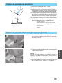
Costura de puntada de recubierto
(1)Determine cuánto tejido se va a doblar.
(2)
Doble el tejido que desee y, a continuación, plánchelo.
(3)Utilice una regla para medirlo y después utilice un
marcador para tela para marcar el derecho del tejido
y ver dónde está colocado el borde del tejido doblado.
(4)Coloque la parte inferior del prensatelas en el derecho
del tejido y, a continuación, compruebe que la marca
dibujada está casi a la derecha de la aguja izquierda.
(5)Cosa exactamente en la marca.
(6)Tras finalizar la costura, véase “Retirada del tejido de
la máquina” en “V. Costura” en la página 33 para
obtener información sobre el manejo del hilo.
1 Tejido (superficie)
2 Marca dibujada con el marcador para tela
3 Aguja izquierda (casi a la izquierda de la marca)
4 Aguja derecha
5 Tejido
6 Aguja
1
3
2
4
6
5
(1)
(2)

36
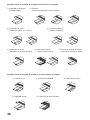
Ejemplos reales de puntada de recubierto de tres hilos y dos agujas
1) Dobladillo de camisetas
(puntada simple)
Ejemplos reales de puntada de recubierto de cuatro hilos y tres agujas
1) Puntada básica 2) Puntada de dobladillo 3) Colocación de cintas
4) Dobladillo circular 5) Colocación de lazos elásticos
2) Puntadas
(costuras sobrepuestas/cintas/canesús)
3) Colocación de cintas
(bordes de cuellos, etc.) (juntas)
4) Costura decorativa
(costura decorativa)
5) Colocación de gomas
(dobladillo con costura de goma)
6) Colocación de lazos
(costura de junta plana)
7) Costura de cinturón de vuelta
(Costura de cinturón de vuelta)

37
ESPAÑOL
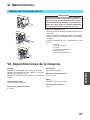
VI. Mantenimiento
Cambio de la bombilla de luz
1
2
3
4
4
5
PRECAUCION
Asegúrese siempre de desconectar la alimenta-
ción antes de realizar la operación siguiente. La
placa de cristal encima de la bombilla se calen-
tará inmediatamente después de utilizar la má-
quina; por tanto, antes de cambiar la bombilla,
es aconsejable esperar hasta que se enfríe.
Cambio de la bombilla de luz.
• Extraiga la tapa de la lámpara como se muestra en la
ilustración.
• Afloje el tornillo de fijación de la tapa de la lámpara,
empuje la tapa de la bombilla de luz hacia arriba y
extráigala.
• Saque la bombilla de luz y reemplácela por otra
nueva.
1 Tornillo
2 Tapa de la lámpara
3 Tornillo
4 Tapa de la bombilla de luz
5 Bombilla de luz
6 Tapa de la bombilla de luz
VII. Especificaciones de la máquina
Puntada
Puntada de cadena doble de un aguja y dos hilos
Puntada de recubierto de dos agujas y tres hilos
(Ancha 6 mm/Estrecha 3 mm)
Puntada de recubierto de tres agujas y cuatro hilos
(6 mm)
Velocidad de costura
1.000 puntadas por minuto
Largo de las puntadas (altura)
2 a 4 mm
Prensatelas
Tipo prensatelas libre
Movimiento del prensatelas
5 mm a 6 mm
Aguja
SCHMETZ 130/705H (90/#14)
Peso neto de la máquina
7,0 kgs

ENGLISH / ESPAÑOL
884-500
XB1148-001
0308
Printed in Taiwan
-
 1
1
-
 2
2
-
 3
3
-
 4
4
-
 5
5
-
 6
6
-
 7
7
-
 8
8
-
 9
9
-
 10
10
-
 11
11
-
 12
12
-
 13
13
-
 14
14
-
 15
15
-
 16
16
-
 17
17
-
 18
18
-
 19
19
-
 20
20
-
 21
21
-
 22
22
-
 23
23
-
 24
24
-
 25
25
-
 26
26
-
 27
27
-
 28
28
-
 29
29
-
 30
30
-
 31
31
-
 32
32
-
 33
33
-
 34
34
-
 35
35
-
 36
36
-
 37
37
-
 38
38
-
 39
39
-
 40
40


Brother Sewing Machine 2340CV Manual de usuario
- Categoría
- Máquinas de coser
- Tipo
- Manual de usuario
- Este manual también es adecuado para
en otros idiomas
Artículos relacionados
-
Brother 2340CV Guía del usuario
-
Brother 884-B01 Manual de usuario
-
Brother 4234D El manual del propietario
-
-
-
-
-
-
