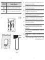
FLOS Skygarden Recessed G9 Guía de instalación
- Tipo
- Guía de instalación

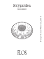
Skygarden
Recessed
Design Marcel Wanders, 2009

2 3
IT
ISTRUZIONI DI INSTALLAZIONE ED IMPIEGO
ATTENZIONE!
La sicurezza dell’apparecchio é garantita solo
rispettando queste istruzioni sia in fase di installazione
che di impiego; é pertanto necessario conservarle.
AVVERTENZE:
• All’atto dell’installazione ed ogni volta che si
interviene sull’apparecchio, assicurarsi che sia stata
tolta la tensione di alimentazione.
• L’apparecchio non può essere in alcun modo
modificato o manomesso, ogni modifica ne può
compromettere la sicurezza rendendo lo stesso
pericoloso. FLOS declina ogni responsabilità per i
prodotti modificati.
• Per la connessione all’alimentazione
dell’apparecchio Utilizzare un cavo 2x (H03VV-F);
• Il simbolo riportato sull’apparecchio indica la
necessità di utilizzare lampade di tipo autoprotetto.
• Il simbolo riportato sull’apparecchio, indica
la distanza minima alla quale va posto il soggetto
da illuminare.
• Il simbolo riportato sull’apparecchio indica che il
prodotto deve essere smaltito in modo differenziato
dai rifiuti urbani.
DATI TECNICI
SKYGARDEN RCS QT-12: Lampada incandescente ad
alogeni MAX 65W attacco Gy6,35 tipo HSGS/IB.
SKYGARDEN RCS G9: Lampada incandescente ad
alogeni MAX 60W attacco G9 tipo HSGS.
EN
INSTRUCTION FOR CORRECT INSTALLATION AND USE
WARNING!
The safety of this fitting can only be guaranteed if these
instructions are observed, during both installation and
use. Please retain these instructions safety.
REMARKS:
• When installing and whenever acting on the
appliance, ensure that the power supply has been
switched off.
• The appliance may in no way be modified or
tampered with, any modification may compromise
safety causing the appliance to become dangerous.
FLOS declines all responsibility for products that are
modified.
• For connection to the power supply of the appliance
use a cable 2x (H03VV-F);
• The symbol marked on the appliance indicates
the need to use self-protected bulbs.
• The symbol shown on the appliance
indicates the minimum permissible distance between
the lamp and the surface to be illuminated.
• The symbol shown on the device indicates
that the product must be thrown out in a different
manner than with the urban trashes.
TECHNICAL DATA
EUR SKYGARDEN RCS QT-12: Incandescent halogen
bulb MAX 65W , Gy6,35 attachment type HSGS/IB;
EUR SKYGARDEN RCS G9: Incandescent halogen bulb
MAX 60W , G9 attachment type HSGS.
USA SKYGARDEN RCS QT-12: Incandescent halogen
bulb MAX 65W , Gy6,35 attachment type T.
USA SKYGARDEN RCS G9: Incandescent halogen bulb
MAX 60W , G9 attachment type T.
DE
INSTALLATION - UND GEBRAUCHSANWEISUNGEN
ACHTUNG!
Wir garantieren nur dann für die Sicherheit der
Leuchte, wenn diese Anweisungen sowohl bei der
Installation als auch beim Gebrauch genau beachtet
werden. Es ist daher ratsam, sie aufzubewahren.
BEMERKUNGEN:
• Bei der Installation und bei Eingriffen an der
Leuchte ist sicherzustellen, daß die Anlage vom Netz
abgeschaltet ist.
• Der Apparat darf auf keinen Fall veraendert oder
unerlaubt geoeffnet werden, jede Veraenderung
desselben kann die Sicherheit in Frage stellen
und somit gefaehrlich werden. FLOS lehnt jede
Verantwortung fuer unsachgemaess behandelte
Produkte ab.
• Für den Anschluss an die Speisung des Geräts ist
ein Kabel 2x (H03VV-F) zu benutzen;
• Das auf der Leuchte wiedergegebene Symbol
zeigt an, dass Glühbirnen des selbstschützenden
Typs zu benutzen sind.
• Das Symbol auf der Leuchte gibt den
Mindestabstand zwischen der Leuchte und dem zu
beleuchtenden Gegenstand an.
• Das auf dem Gerät wiedergegebene Symbol
zeigt an, dass das Produkt getrennt vom Stadtmüll
entsorgt werden muss.
TECHNISCHE DATEN
SKYGARDEN RCS QT-12: Halogen-Glühlampe MAX 65W,
Fassung Gy6,35, typ HSGS/IB.
SKYGARDEN RCS G9: Halogen-Glühlampe MAX 60W,
Fassung G9, typ HSGS.
FR
INSTRUCTIONS D’INSTALLATION ET D’EMPLOI
ATTENTION!
La sûreté de cet appareil est garantie uniquement si l’on
respecte ces instructions soit en phase d’installation
soit pendant l’utilisation; il faut donc les conserver.
NOTICES:
• Au moment de l’installation et chaque fois que l’on
intervient sur l’appareil, s’assurer que la tension
d’alimentation ait été coupée.
• L’appareil ne peut être modifié ou altéré de quelque
manière que ce soit, toute modification peut
compromettre la sécurité de celui-ci en le rendant
dangereux. FLOS décline toute responsabilité pour
les produits modifiés.
• Pour la connexion à l’alimentation de l’appareil,
utiliser un câble 2x(H03VV-F);
• Le symbole reporté sur l’appareil indique la
nécessité d’utiliser des ampoules de type “auto-
protégé”.
• Le symbole marqué sur l’appareil indique
la distance minime entre la lampe-même et l’objet
à illuminer.
• Le symbole montré sur l’appareil indique que le
produit doit être éliminé d’une autre façon que celle
avec les déchets urbains.
DONNEES TECHNIQUES:
EUR SKYGARDEN RCS QT-12: Ampoule incandescente
à halogènes MAX 65W, douille Gy6,35, type HSGS/IB.
EUR SKYGARDEN RCS G9: Ampoule incandescente à
halogènes MAX 60W, douille G9, type HSGS.
USA SKYGARDEN RCS QT-12: Ampoule incandescente
à halogènes MAX 65W, douille Gy6,35, type T.
USA SKYGARDEN RCS G9: Ampoule incandescente à
halogènes MAX 60W, douille G9, type T.

4 5
ES
INSTRUCCIONES DE INSTALACIÓN Y DE USO
¡ATENCIÓN!
La seguridad del aparato sólo puede garantizarse
con la condición de que se respeten las siguientes
instrucciones, tanto en la fase de instalación como de
uso, por lo cual se recomienda conservarlas.
ADVERTENCIA:
• Para efectuar la instalación, y toda vez que se
efectúe alguna operación en el aparato, asegurarse
de haber cortado la corriente eléctrica.
• El aparato no puede ser en ningùn caso modificado
o forzado, cualquier modificaciòn puede
comprometer la seguridad haciéndolo peligroso.
FLOS declina cualquier responsabilidad por los
productos modificados.
• Para la conexión al equipo de alimentación del
aparato utilizar un cable 2x (H03VV-F);
• El símbolo marcado en el aparato indica
la necesidad de utilizar bombillas de tipo
autoprotegido.
• El simbolo reproducido en el aparato indica
la distancia mnima a la cual debe colocarse el objeto
a iluminar.
• El símbolo que aparece en el aparato indica
que el producto debe ser eliminado en modo
diferenciado del resto de los desechos urbanos.
DATOS TECNICOS:
EUR SKYGARDEN RCS QT-12: Bombilla de incandescencia
alógena max 65W conexión Gy6,35 tipo HSGS/IB.
EUR SKYGARDEN RCS G9: Bombilla de incandescencia
alógena max 60W conexión G9 tipo HSGS.
USA SKYGARDEN RCS QT-12: Bombilla de
incandescencia alógena max 65W conexión Gy6,35
tipo T.
USA SKYGARDEN RCS G9: Bombilla de
incandescencia alógena max 60W conexión G9 tipo T.
PT
INSTRUÇÕES INSTALAÇÃO E USO
ATENÇÃO!
A segurança do aparelho é garantida somente se
respeitarmos as instruções tanto na fase de instalação
como na de uso; portanto é necessário conservar tais
instruções.
ADVERTÊNCIA:
• Para efectuar la instalación, y toda vez que se
efectúe alguna operación en el aparato, asegurarse
de haber cortado la corriente eléctrica.
• De forma alguma o aparelho deve ser modificado
ou alterado, toda e qualquer modificação pode
comprometer a segurança tornando o aparelho
perigoso. FLOS declina toda e qualquer
responsabilidade pelos produtos modificados.
• Para a conexão à alimentação do aparelho utilizar
um cabo 2x (H03VV-F);
• O símbolo indicado no aparelho indica a
necessidade de utilizar lâmpadas com blindagem
externa.
• O símbolo colocado no aparelho indica a
distância mínima onde se colocar o objeto a ser
iluminado.
• O símbolo indicado no aparelho indica que o
produto deve ser eliminado de forma diferenciada
em relação ao lixo urbano.
DADOS TÉCNICOS:
SKYGARDEN RCS QT-12: Lâmpada incandescente
alógena MAX 65W ligação Gy6,35 tipo HSGS/IB.
SKYGARDEN RCS G9: Lâmpada incandescente alógena
MAX 60W ligação G9 tipo HSGS.
RUS
ИНСТРУКЦИИ ПО МОНТАЖУ И ПРИМЕНЕНИЮ
ВНИМАНИЕ!
Надёжность устройства гарантируется только
при соблюдении данных инструкций, как в
фазе монтажа, так и при применении, поэтому
необходимо обеспечить их сохранность.
ПРЕДУПРЕЖДЕНИЯ:
• В момент установки и каждый раз при
проведении работ с устройством, убедиться в
снятии напряжения питания.
• Устройство не может изменяться или
разбираться, любые изменения могут нарушить
надёжность, делая его опасным. FLOS не несёт
ответственность за измененную продукцию.
• Для подсоединения устройства к источнику
питания использовать кабель 2x (H03VV-F).
• Обозначение приведённое на устройстве,
указывает на необходимость использования
самозащищаемых лампочек.
• Обозначение приведенное на устройстве,
указывает минимальное расстояние, на котором
должен располагаться освещаемый объект.
• Символ приведённый на устройстве,
указывает на то, что данная продукция должна
быть переработана отдельно от городских
отходов.
ТЕХНИЧЕСКИЕ ДАННЫЕ:
SKYGARDEN RCS QT-12: Аллогенная лампочка
накаливания макс.65Вт цоколь Gy6,35 тип HSGS/
IB.
SKYGARDEN RCS G9: Аллогенная лампочка
накаливания макс.60Вт цоколь G9 тип HSGS.
J

IT ISTRUZIONI PER LA PULIZIA DELL’APPARECCHIO
Per la pulizia dell’apparecchio utilizzare esclusivamente un panno morbido eventualmente inumidito con acqua
e sapone. Attenzione: non utilizzare alcool o solventi.
EN CLEANING INSTRUCTIONS
Use only a soft cloth to clean the appliance, dampened with water and soap or mild cleanser if needed for
resistant dirt. Warning: do not use alcohol or other solvents.
DE REINIGUNGSVORSCHRIFTEN
Bei der Reinigung der Leuchte darf man ausschließlich weiche Tücher verwenden. Eventuell kann man diese
mit Wasser und Seife oder mit einem neutralen Reinigungsmittel anfeuchten. Achtung: Weder Alkohol noch
Lösungsmittel verwenden.
FR INSTRUCTIONS POUR LE NETTOYAGE
Pour le nettoyage de l’appareil utiliser exclusivement un chiffon doux, humecté si nécessaire, avec de l’eau et
du savon ou avec un détergent neutre pour les salissures les plus tenaces. Attention: ne pas utiliser d’alcool
ou solvents.
ES INSTRUCCIONES PARA LIMPIAR EL APARATO
Para la limpieza del aparato, utilizar exclusivamente un paño suave. En caso de suciedad más resistente,
humedecer el paño con agua y jabón o un detergente neutro. Advertencia: no emplear alcohol ni disolventes.
PT INSTRUÇÕES PARA A LIMPEZA DO APARELHO
Para limpeza do aparelho utilizar exclusivamente um tecido macio eventualmente úmido com água e sabão ou
detergente neutro para a sujeira mais difícil. Atenção: não utilizar álcool ou solventes.
RUS ИНСТРУКЦИИ ПО ОЧИСТКЕ УСТРОЙСТВА
Для очистки устройства использовать только мягкую тряпку, смоченную водой с мылом
или нейтральным моющим средством для наиболее стойких загрязнений. Внимание: Не
использовать спирт или другие растворители.
J
CN
SA
6 77
CN
•
SA
•
•
FLOS
•
•
•
•

VERSION Assembly Sequence
EUR Fig.1 - 2 - 3e - 4e - 5e - 6e -7e - 8 - 9 - 10.
USA Fig.1 - 2 - 3u - 4u - 5u - 6u -7u - 8 - 9 - 10.
8 9
41 cm
16,14 inches
16,14 inches
3 cm
1,18 inches
41 cm
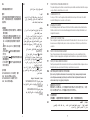
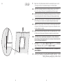
Fig.1
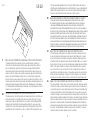
Fig.1 Predisporre nel controsoffitto un foro quadrato di 410 x 410 mm. NOTA BENE: predisporre il foro con un
bordo smussato con dimensioni come indicato in figura.
Pic.1 Cut out a square hole in the false ceiling, 410 x 410 mm (16,14 x 16,14 inches). NOTE: Cut the hole and
smooth the edge with the dimensions shown in the figure.
Abb.1 In die Zwischendecke eine viereckige Öffnung von 410 x 410 mm ausführen. Zu Beachten: Die Öffnung
wie in der Abbildung gezeigt mit einer abgeschrägten Kante vorbereiten.
Fig.1 Faire un percement carré de 410 x 410 mm (16,14 x 16,14 inches) dans le faux-plafond. NOTA BENE:
prévoir le trou avec un bord biseauté selon les dimensions indiquées sur le schéma.
Imag.1 Preparar en el falso techo un agujero cuadrado de 410 x 410 mm (16,14 x 16,14 inches). NOTA
IMPORTANTE: preparar el agujero con un borde biselado con las dimensiones como se indica en la figura.
Fig.1 Fazer no controtecto um furo quadrado de 410 x 410 mm. OBSERVAR BEM: Fazer o furo com a borda
chanfrada com as dimensões como indicado na figura
Подготовить на подвесном потолке квадратное отверстие размером 410 х 410 мм.
ПРИМЕЧАНИЕ: Отверстие должно быть со скошенным краем в соответствии с размерами,
указанными на рисунке.
IT
EN
DE
FR
ES
PT
RUS
J
CN
EUR-USA
SA

10 11
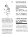
Fig.2 Fig.2 Inserire le staffe (A) fornita in dotazione all’interno del foro, avendo cura di far sporgere le stesse di 30
mm nello spazio vuoto. Fissare le staffe alla struttura in cartongesso con le viti fornite in dotazione.
Pic.2 Insert the enclosed brackets (A) inside the hole, remembering to allow these to project 30 mm (1,18
inches ) into the empty space. Fix the brackets to the plasterboard structure with the screws supplied.
Abb.2 Die mitgelieferten Bügel (A) in die Öffnung einfügen, wobei darauf zu achten ist, dass sie 30 mm in den
freien Raum hineinragen. Bügel mit den mitgelieferten Schrauben an die Struktur aus Gipskarton befestigen.
Fig.2 Insérerles étriers (A) fournis dans le colis à l'intérieur du percement, en ayant soin de les faire dépasser de
30 mm (1,18 inches ) vers le vide. Fixer les étriers à la structure en Placoplatre à l'aide des vis fournies.
Imag.2 Inserir los soportes (A), que se entregan con el producto, en el interior del agujero, haciendo sobresalir
los mismos de 30 mm (1,18 inches ) hacia el espacio vacío. Fijar los soportes a la estructura del falso techo con
los tornillos suministrados con el producto.
Fig.2 Inserir as guias (A) fornecidas em dotação dentro do furo, tendo o cuidado de deixar para fora as mesmas
de 30mm no espaço vazio. Fixar as guias à estrutura em gesso cartonado com os parafusos em dotação.
Вставить скобы (А), предоставленные в принадлежностях, в отверстие, обеспечивая их
выступ на 30 мм в пустом пространстве. Закрепить скобы к структуре из гипсокартона посредством
винтов, предоставленных в принадлежностях.
IT
EN
DE
FR
ES
PT
RUS
J
CN
SA
A
EUR-USA

12 13
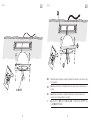
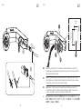
Fig.3e
2x (H03VV-F)
Fig.3u
Pic.3u After having passed through the conduit (B) (not provided), fix the lamp body (C) to the brackets (A), using
the screws supplied.
Fig.3u Après avoir fait traverser le conduit (B) (non fourni), fixer le corps de la lampe (C) aux étriers (A) avec les
vis fournies.
Imag.3u Después de haber pasado el conduit (B) (no suministrado), fijar el cuerpo de la lámpara (C) a los
soportes (A), con los tornillos suministrados con el producto.
EN
FR
ES
J
EUR USA
A
B
C

14 15
Fig.4e EUR Fig.4u
Pic.4u Loosen the screw (D) and open the hatch (E) on the handle (F). Remove the piece (Z) with the phrase
"remove for UL".
Fig.4u Dévisser les vis (D) et ouvrir le capot (E) de la poignée (F). Oter la partie rabattable (Z) qui porte
l’indication "remove for UL".
Imag.4u Desatornillar el tornillo (D) y abrir la tapa (E) del tirador (F). Retirar la pieza (Z) que lleva la frase escrita
"remove for UL".
EN
FR
ES
J
USA
1
2
D
Z
Z
E
F

16 17
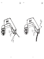
Fig.5e EUR
1
2
0,746 inches
0,826 inches
(19 mm)
(21 mm)
Fig.5u
Pic.5u Fix the conduit to the hole (Y) of the lid (E) using a compatible straight squeeze connector (X) (not
provided)with the hole dimmensions indicated in figure. Then, carry outthe electrical connections; (white with
white, black with black) inside the handle.
Fig.5u Fixer le conduit au percement (Y) du clapet (E) en utilisant un "straight squeeze connector " (X) (non
fourni) compatibles avec les dimensions du trou comme indiqué sur le schéma; puis effectuer les connexions
électriques (blanc avec blanc, noir avec noir) à l’intérieur de la poignée.
Imag.5u Sujetar el "conduit" al agujero (Y) de la tapa (E) utilizando un "straight squeeze connector" (X)
(no suministrado) compatible con las dimensiones del agujero indicadas en la figura; efectuar entonces las
conexiones eléctricas (blanco con blanco, negro con negro) en el interior del tirador..
EN
FR
ES
J
USA
YY
E
X

18 19
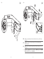
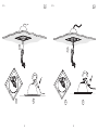
Fig.6e Fig.6u
EUR USA
11
2
2

20 21
Fig.7e Fig.7u
EUR USA
1
2
1
332

22 23
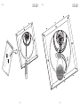
Fig.8 Fig.9
EUR-USA EUR-USA
1
2
3

24 25
Fig.10
Fig.10 CONSIGLI PER IL TRATTAMENTO DELLA GIUNZIONE NELLA CONTROSOFFITTATURA IN CARTONGESSO
1) Operazioni preliminari - Verificare la planarità e il corretto accostamento delle parti; controllare che le
teste delle viti siano correttamente posizionate; eliminare la polvere dalle superfici da trattare. 2) Nastri per
giunti - L’esecuzione di giunti a regola d’arte è semplificata ed accelerata grazie all'utilizzo di: A) Nastro in
carta microforata ad alta resistenza meccanica. B) Giunti con nastro di rinforzo (rete adesiva). In questo caso
procedere come descritto: • Stendere lo stucco sul giunto con una spatola; • Applicare il nastro di rinforzo (rete
adesiva); • Serrare il nastro eliminando nel contempo lo stucco in eccedenza; • Riempire completamente il
giunto con la spatola; • Lasciare asciugare per il tempo necessario a seconda dello stucco utilizzato; • A presa o
essicamento avvenuti, rasare il giunto con la spatola, avendo cura di eliminare ogni irregolarità superficiale; • Una
eventuale ulteriore rasatura è da valutare in funzione del rivestimento o finitura da applicare. 3) Stuccatura delle
viti - Contemporaneamente al trattamento dei giunti, si realizzano due o tre strati di copertura delle teste delle viti,
lasciando esiccare lo stucco dopo ogni strato.
Pic.10 ADVICE FOR THE TREATMENT OF JOINTS IN THE PLASTERBOARD FALSE CEILING
1) Preliminary operations – Check the flatness and the correct juxtapositioning of the parts; check that the screw
heads are positioned correctly; clean the dust from the surfaces to be treated. 2) Tape for joints - The correct
execution of joints is made easier and faster thanks to the use of: A) Tape in micro-perforated paper with high
mechanical resistance. B) Joints with reinforcement tape (adhesive netting). In this case proceed as follows:
• Spread the stucco onto the joint with a spatula; • Apply the reinforcement tape (adhesive netting); • Pull the
tape tight and at the same time eliminate the excess stucco; • Completely fill the joint using a spatula; • Leave
IT
EN
for the time required to dry, depending on the type of stucco used; • When it has taken or dried, scrape the
joint with the spatula, eliminating all irregular surfaces; • Further smoothing is to be assessed depending on the
cladding or finish to be applied. 3) Stucco on screws - At the same time when treating the joints, apply two or
three layers of cover on the heads of the screws, allow the stucco to dry after each layer.
Abb.10 EMPFEHLUNGEN FÜR DIE AUSFÜHRUNG DER FUGEN IN DER ZWISCHENDECKE AUS GIPSKARTON
1) Vorbereitung – Ebenheit und die korrekte Annäherung der Teile prüfen; kontrollieren, dass die Köpfe
der Schrauben richtig platziert sind; Staub von den zu behandelnden Flächen entfernen. 2) Fugenstreifen
– Die kunstgerechte Durchführung der Fugen wird wie folgt vereinfacht und beschleunigt: A) Hochfeste
Papierfugendeckstreifen. B) Fugen mit Befestigungsband (Klebenetz). In diesem Fall ist wie folgt vorzugehen: •
Spachtelmasse mit einem Spachtel auftragen; • Befestigungsband (Klebenetz) anbringen; • Band fest andrücken
und gleichzeitig die überflüssige Spachtelmasse entfernen; • Fuge vollkommen mit dem Spachtel füllen; • Je
nach verwendeter Spachtelmasse trocknen lassen; • Nach erfolgter Erhärtung oder Trocknung ist die Fuge mit
dem Spachtel zu glätten, wobei darauf zu achten ist, jede Unregelmäßigkeit der Oberfläche zu beseitigen; eine
eventuelle weitere Glättung ist je nach der anzuwendenden Beschichtung oder Feinbearbeitung zu bewerten. 3)
Vergipsen der Schrauben - Gleichzeitig mit der Behandlung der Fugen werden zwei oder drei Schichten für die
Abdeckung der Schraubenköpfe realisiert, wobei die Spachtelmasse nach jeder Schicht trocknen muss.
Fig.10 CONSEILS SUR LE TRAITEMENT DES JOINTS DANS LE FAUX-PLAFOND EN PLACOPLATRE
1) Operations préalables - Vérifier la planéité et l'assemblage correct des parties ; contrôler que les têtes des
vis soient correctement placées, éliminer la poussière des surfaces à traiter. 2) Rubans à joints - L'exécution
des joints selon les règles de l'art est simplifiée et accélérée grâces l'utilisation de: A) ruban en papier micro
perforé à haute résistance mécanique. B) des joints avec ruban de renfort (adhésif). Dans ce cas, il convient de
procéder comme suit: • étendre le stuc sur le joint à l'aide d'une spatule; • Applique le ruban de renfort (ruban
adhésif); • Serrer le ruban en éliminant l'excès de mastic; • Remplir complètement le joint avec la spatule; •
Laisser sécher le temps nécessaire selon le stuc utilisé; • Une fois le séchage terminé, raser le joint avec la
spatule afin d'éliminer toute irrégularité à la surface; • Un rasage ultérieur peut s'avérer nécessaire en fonction
du revêtement ou de la finition à appliquer. 3) Stucage des vis - En même temps que les joints, il convient de
réaliser deux ou trois couches de couverture des têtes de vis, en laissant sécher le stuc après chaque couche.
Imag.10 CONSEJOS PARA EL TRATAMIENTO DE LA JUNTA EN EL FALSO TECHO DE ESCAYOLA
1) Operaciones preliminares - Verificar el nivel y el correcto ensamblaje de las partes; controlar que la cabeza de
los tornillos estén colocadas correctamente; eliminar el polvo de las superficies a tratar. 2) Cinta para juntas - La
ejecución de juntas perfectas se acelera y simplifica gracias al uso de: A) Cinta de papel microperforado de alta
resistencia mecánica. B) Juntas con cinta de refuerzo (red adhesiva). En este caso proceder como se describe
a continuación: • Extender el estuco por encima de la junta con una espátula; • Aplicar la cinta de refuerzo (red
adhesiva); • Apretar la cinta adhesiva eliminando al mismo tiempo el estuco sobrante; • Rellenar completamente
la junta con la espátula; • Dejar secar el tiempo necesario según el estuco que se haya utilizado; • Una vez seco,
igualar la junta con la espátula, eliminando con cuidado cualquier irregularidad superficial; • Eventualmente se
valorará un posible enrasado posterior en función al revestimiento o acabado que se desee aplicar. 3) Estucado
de los tornillos - Contemporáneamente al tratamiento efectuado a las juntas, se realizan dos o tres capas de
cobertura en las cabezas de los tornillos, dejando secar el estuco en cada capa.
DE
FR
ES
EUR-USA

32323 - 14/09/2021
26 27
Fig.10
Fig.10 CONSELHOS PARA O TRATAMENTO DA JUNÇÃO NO CONTROTECTO EM GESSO CARTONADO
1) Operações preliminares - Verificar a planicidade e o correcto contacto das partes; controlar que as cabeças
dos parafusos estejam correctamente colocadas; eliminar a poeira das superfícies à tratar. 2) Fitas para juntas -
A execução de juntas bem feitas é simplificada e acelerada graças ao uso de: A) Fita em papel microfurado com
alta resistência mecânica. B) Juntas com fitas de reforço (rede adesiva). Neste caso seguir as instruções a seguir:
• Passar o estuque na junta com uma espátula; • Aplicar a fita de reforço (rede adesiva); • Fechar a fita
eliminando neste meio tempo o estuque em excesso; • Encher completamente a junta com a espátula;
• Deixar enxugar pelo tempo necessário de acordo com o estuque utilizado; • Depois de seco, alisar a junta
com a espátula, tendo o cuidado de eliminar qualquer irregularidade superficial; • Um outro eventual alisamento
deve ser avaliado em função do revestimento ou do acabamento a ser aplicado. 3) Estuque dos parafusos -
Contemporaneamente ao tratamento das juntas, se realizam dois ou três extractos de cobertura na cabeça dos
parafusos, deixando a secar o estuque depois de cada passada.
РЕКОМЕНДАЦИИ ДЛЯ ОБРАБОТКИ СОЕДИНЕНИЯ В ГИПСОКАРТОННОМ ПОДВЕСНОМ
ПОТОЛКЕ 1) Предварительные операции - Проверить плоскостность и соответствующее
соединение компонентов, правильное позиционирование головок винтов, удалить пыль с
обрабатываемых поверхностей. 2) Ленты для соединений - Соответствующее исполнение
соединений упрощается и ускоряется благодаря использованию: А) Ленты из высокопрочной
микроперфорированной бумаги. В) Соединений с укрепляющей лентой (клейкая сетка).
PT
В данном случае действовать следующим образом: • Намазать шпатлевку на соединение
посредством шпателя. • Позиционировать укрепляющую ленту (клейкую сетку). • Закрепить
ленту, удаляя излишнюю шпатлевку. • Полностью заполнить соединение посредством шпателя.
• Оставить для высыхания на необходимое время, в зависимости от использованной шпатлевки.
• После схватывания или высыхания, выровнять соединение посредством шпателя, удаляя
все поверхностные неровности. • Дополнительное выравнивание должно осуществляться в
соответствии с наносимым покрытием или отделкой. 3) Замазывание винтов - Одновременно с
обработкой соединений, наносятся два или три слоя на головки винтов, обеспечивая высыхание
шпатлевки после каждого слоя.
J
CN
EUR-USA
RUS
SA

flos.com
-
 1
1
-
 2
2
-
 3
3
-
 4
4
-
 5
5
-
 6
6
-
 7
7
-
 8
8
-
 9
9
-
 10
10
-
 11
11
-
 12
12
-
 13
13
-
 14
14
-
 15
15


FLOS Skygarden Recessed G9 Guía de instalación
- Tipo
- Guía de instalación
En otros idiomas
Documentos relacionados
-
 FLOS IC Lights Ceiling/Wall 1 Guía de instalación
-
 FLOS IC Lights C/W1 Double Guía de instalación
-
 FLOS IC Lights Floor 1 Guía de instalación
-
 FLOS Glo-Ball Table 1 Guía de instalación
-
 FLOS Tatou Floor Guía de instalación
-
 FLOS Romeo Moon Suspension 1 Guía de instalación
-
 FLOS Glo-Ball Wall Guía de instalación
-
 FLOS KTribe Table 1 Glass Guía de instalación
-
 FLOS Ray Table Guía de instalación
-
 FLOS Glo-Ball Suspension 1 Guía de instalación


