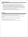
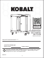
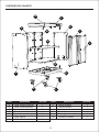
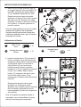
El Kobalt 0019002 es un gabinete base con 2 puertas de 71,12 cm, diseñado para brindar soluciones de almacenamiento versátiles y duraderas en espacios residenciales o de trabajo. Con una capacidad máxima de carga de 100 libras para la superficie superior de madera, 100 libras para el estante inferior y 100 libras para el estante ajustable, ofrece una capacidad total de carga de 300 libras.
El Kobalt 0019002 es un gabinete base con 2 puertas de 71,12 cm, diseñado para brindar soluciones de almacenamiento versátiles y duraderas en espacios residenciales o de trabajo. Con una capacidad máxima de carga de 100 libras para la superficie superior de madera, 100 libras para el estante inferior y 100 libras para el estante ajustable, ofrece una capacidad total de carga de 300 libras.


-
 1
1
-
 2
2
-
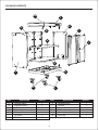 3
3
-
 4
4
-
 5
5
-
 6
6
-
 7
7
-
 8
8
-
 9
9
-
 10
10
-
 11
11
-
 12
12
-
 13
13
-
 14
14
-
 15
15
-
 16
16
-
 17
17
-
 18
18
-
 19
19
-
 20
20


El Kobalt 0019002 es un gabinete base con 2 puertas de 71,12 cm, diseñado para brindar soluciones de almacenamiento versátiles y duraderas en espacios residenciales o de trabajo. Con una capacidad máxima de carga de 100 libras para la superficie superior de madera, 100 libras para el estante inferior y 100 libras para el estante ajustable, ofrece una capacidad total de carga de 300 libras.
en otros idiomas
- English: Kobalt 0019002 User manual