Husqvarna 917380961 El manual del propietario
- Categoría
- Cortadoras de césped
- Tipo
- El manual del propietario

Owner's Manual
sqva
OTARY
173cc Kohler
22" Multi-Cut
LAWN
Engine
Self-Propelled
Model No.
917.380961
Product No.
38096
®
MOWER
• EspaSol, p. 23
CAUTION'.
Read and follow all
Safety Rules and Instructions
before operating this equipment
Husqvarna, Charlotte, NC 28269
Visit our website: www.husqvarna.com
U.S.A.

Safety Rules .......................................... 2-3
Warranty ................................................ 4-7
Product Specifications .............................. 8
Assembly / Pre-Operation ........................ 9
Operation ........................................... 10-14
Maintenance Schedule ........................... 15
Maintenance ...................................... 15-18
Service and Adjustments ................... 19-20
Storage .............................................. 20-21
Troubleshooting ................................. 21-22
Repair Parts ....................................... 44-55
IMPORTANT: This cutting machine iscapable of amputating hands and feet and throwing ob-
jects. Failure to observe the following safety instructions could result in serious injury or death.
ALook for this symbol to point out im-
portant safety precautions. It means
CAUTION!!! BECOME ALERT!!!
YOUR SAFETY IS INVOLVED.
&WARNING" In order to prevent accidental
starting when setting up, transporting, ad-
justing or making repairs, always disconnect
spark plug wire and place wire where itcannot
come in contact with plug.
AWARNING" Engine exhaust, some of its
constituents, and certain vehicle compo-
nents contain or emit chemicals known to
the State of California to cause cancer and
birth defects or other reproductive harm.
AWARNING" Battery posts, terminals and
related accessories contain lead and lead
compounds, chemicals known to the State
of California to cause cancer and birth
defects or other reproductive harm. Wash
hands after handling.
A CAUTION" Muffler and other engine
parts become extremely_
hot during operation and
remain hot after engine
has stopped. To avoid
severe burns on contact,
stay away from these areas.
I. GENERAL OPERATION
• Read, understand, and follow all
instructions on the machine and in the
manual(s) before starting. Be thoroughly
familiar with the controls and the proper
use of the machine before starting.
• Do not put hands or feet near or under
rotating parts. Keep clear of the dis-
charge opening at all times.
• Only allow responsible individuals, who
are familiar with the instructions, to
operate the machine.
• Clear the area of objects such as rocks,
toys, wire, bones, sticks, etc., which could
be picked up and thrown by blade.
• Be sure the area is clear of other people
before mowing. Stop the machine if
anyone enters the area.
• Do not operate the mower when bare-
foot or wearing open sandals. Always
wear substantial foot wear.
• Do not pull mower backwards unless abso-
lutely necessary. Always Iookdown and be-
hind before and while moving backwards.
• Never direct discharged material toward
anyone. Avoid discharging material
against a wall or obstruction. Material may
richochet back toward the operator. Stop
the blade when crossing gravel surfaces.
• Do not operate the mower without prop-
er guards, plates, grass catcher or other
safety protective devices in place.
• See manufacturer's instructions for
proper operation and installation of
accessories. Only use accessories ap-
proved by the manufacturer.
• Stop the blade(s) when crossing gravel
drives, walks, or roads.
• Stop the engine (motor) whenever you
leave the equipment, before cleaning
the mower or unclogging the chute.
• Shut the engine (motor) off and wait
until the blade comes to complete stop
before removing grass catcher.
• Mow only in daylight or good artificial light.
• Do not operate the machine while under
the influence of alcohol or drugs.
• Never operate machine in wet grass.
Always be sure of your footing: keep a
firm hold on the handle; walk, never run.
• Disengage the self-propelled mech-
anism or drive clutch on mowers so
equipped before starting the engine.
• If the equipment should start to vibrate
abnormally, stop the engine (motor) and
check immediately for the cause. Vibra-
tion is generally a warning of trouble.
• Always wear safety goggles or safety glass-
es with side shields when operating mower.
II. SLOPE OPERATION
Slopes are a major factor related to slip &
fall accidents which can result in severe
injury. All slopes require extra caution. If
2 you feel uneasy on a slope, do not mow it.

DO:
• Mow across the face of slopes: never
up and down. Exercise extreme caution
when changing direction on slopes.
• Remove obstacles such as rocks, tree
limbs, etc.
• Watch for holes, ruts, or bumps. Tall
grass can hide obstacles.
DO NOT:
• Do not trim near drop-offs, ditches or
embankments. The operator could lose
footing or balance.
• Do not trim excessively steep slopes.
• Do not mow on wet grass. Reduced
footing could cause slipping.
III. CHILDREN
Tragic accidents can occur if the operator is
not alert to the presence of children. Children
are often attracted to the machine and the
mowing activity. Neverassume that children
will remain where you last saw them.
* Keep children out of the trimming area
and under the watchful care of another
responsible adult.
* Be alert and turn machine off if children
enter the area.
* Before and while walking backwards,
look behind and down for small children.
* Never allow children to operate machine.
* Use extra care when approaching blind
corners, shrubs, trees, or other objects
that may obscure vision.
IV. SAFE HANDLING OF GASOLINE
Use extreme care in handling gasoline.
Gasoline is extremely flammable and the
vapors are explosive.
* Extinguish all cigarettes, cigars, pipes
and other sources of ignition.
* Use only an approved container.
* Never remove gas cap or add fuel with
the engine running. Allow engine to
cool before refueling.
* Never refuel the machine indoors.
* Never store the machine or fuel contain-
er where there is an open flame, spark
or pilot light such as a water heater or
on other appliances.
* Never fill containers inside a vehicle, on
a truck or trailer bed with a plastic liner.
Always place containers on the ground
away from your vehicle before filling.
* Remove gas-powered equipment from
the truck or trailer and refuel it on the
ground. If this is not possible, then
refuel such equipment with a portable
container, rather than from a gasoline
dispenser nozzle.
* Keep the nozzle in contact with the rim
of the fuel tank or container opening at
all times until fueling is complete. Do
not use a nozzle lock-open device.
* If fuel is spilled on clothing, change
clothing immediately.
* Never overfill fuel tank. Replace gas
cap and tighten securely.
V. GENERAL SERVICE
* Never run machine inside a closed area.
* Never make adjustments or repairs with
the engine (motor) running. Disconnect the
spark plug wire, and keep the wire away
from the plug to prevent accidental starting.
* Keep nuts and bolts, especially blade
attachment bolts, tight and keep equip-
ment in good condition.
* Never tamper with safety devices.
Check their proper operation regularly.
* Keep machine free of grass, leaves, or
other debris build-up. Clean oil or fuel spill-
age. Allow machine to cool before storing.
* Stop and inspect the equipment if you
strike an object. Repair, if necessary,
before restarting.
* Never attempt to make wheel height
adjustments while the engine is running.
* Grass catcher components are subject to
wear, damage, and deterioration, which
could expose moving parts orallow objects
to be thrown. Frequently check compo-
nents and replace with manufacturer's
recommended parts, when necessary.
* Mower blades are sharp and can cut.
Wrap the blade(s) or wear gloves, and
use extra caution when servicing them.
* Do not change the engine governor set-
ting or overspeed the engine.
* Maintain or replace safety and instruc-
tion labels, as necessary.
AWARN[NG: This lawn mower is equipped with an internal combustion engine and
should not be used on or near any unimproved forest-covered, brush-covered or
grass-covered land unless the engine's exhaust system is equipped with a spark
arrester meeting applicable local or state laws (if any). If a spark arrester is used, it
should be maintained in effective working order by the operator.
Inthe state of California the above is required by law (Section 4442 of the California Public
Resources Code). Other states may have similar laws. Federal laws apply on federal
lands. A spark arrester for the muffler is available through your nearest Husqvarna or
other authorized service center (See the REPAIR PARTS section of this manual).
3

Husqvarna
Consumer Wheeled Products - Limited Warrant_
Husqvarna warrants to the original retail purchaser that this Husqvarna,_R_' product is free from defects in material or work-
manshil_ under normal use and maintenance from the date of retail purchase for the applicable Warranty Period shown on
Exhibit A. This Limited Warranty may not be transferred to any subsequent prochaser of this Husqvarna,_R_' product. Certain
components (e.g., engines and transmissions) are excluded from coverage, and other limitations apply, as described in this
document. Husqvarna will repair or replace at its discretion, any defective product or part covered by the Limited Warranty,
free of charge at any authorized Husqvarna Servicing Dealer/Center using original OEM Husqvarna replacement parts, sub-
ject to the limitations and exclusions described below. Husqvama does not offer an over-the-counter exchange program.
DISCLAIMERS, LIMITATIONS AND EXCLUSIONS
1. WARRANTY DISCLAIMER. THIS LIMITED WARRANTY IS THE SOLE EXPRESS WARRANTY PROVIDED
BY HUSQVARNA AND THERE ARE NO WARRANTIES WHICH EXTEND BEYOND THE DESCRIPTION ON THE
FACE HEREOF, EXCEPT AS MAY BE PROVIDED BY LAW. THIS WARRANTY IS GIVEN ONLY BY HUSQVARNA,
AND MAY BE MODIFIED ONLY BY HUSQVARNA. THIS LIMITED WARRANTY IS THE FINAL EXPRESSION OF
OUR AGREEMENT, AND IS A COMPLETE AND EXCLUSIVE STATEMENT OF THE TERMS OF THAT AGREE-
MENT. THIS LIMITED WARRANTY GIVES YOU SPECIFIC LEGAL RIGHTS, AND YOU MAY ALSO HAVE OTHER
RIGHTS WHICH VARY BASED ON LOCALITY
2. LIMITED DURATION. ANY WARRANTY THAT MAY BE IMPLIED BY LAW (INCLUDING ANY IMPLIED
WARRANTY OF FITNESS FOR A PARTICULAR PURPOSE OR USE AND IMPLIED WARRANTY OF MERCHANT-
ABILITY) IS LIMITED TO THE DURATION OF THE APPLICABLE WARRANTY PERIOD UNDER THIS LIMITED
WARRANTY. SOME LOCALITIES DO NOT ALLOW LIMITATIONS ON HOW LONG AN IMPLIED WARRANTY
LASTS, SO THE ABOVE LIMITATIONS MAY NOT APPLY TO YOU.
3. EXCLUSIVE REMEDIES. SOME LOCALITIES, INCLUDING THE PROVINCE OF QUEBEC, DO NOT ALLOW
THE EXCLUSION OR LIMITATION OF LIABILITY FOR INJURY TO PERSON OR FOR DAMAGES RESULTING
FROM THE FAULT OF THE MANUFACTURER AND/OR THE EXCLUSION OR LIMITATION OF INCIDENTAL OR
CONSEQUENTIAL DAMAGES. AS SUCH, SOME OF THE FOLLOWING LIMITATIONS MAY NOT APPLY TO YOU.
THE ABOVE REMEDIES ARE THE EXCLUSIVE REMEDIES FOR ANY BREACH OF THIS LIMITED WARRANTY.
NO OTHER REMEDY, INCLUDING, BUT NOT LIMITED TO ANY SPECIAL, INCIDENTAL, INDIRECT OR CONSE-
QUENTIAL DAMAGES, FOR LOST PROFITS, LOST SALES, INJURY TO PERSON OR PROPERTY, OR ANY OTHER
INCIDENTAL OR CONSEQUENTIAL LOSS SHALL BE AVAILABLE, AND ALL SUCH DAMAGES ARE HEREBY
DISCLAIMED.
4. Engines, Transmissions and certain other components are NOT covered. This Limited Warranty does not cover any of
the t\_llowing:
(a) Etlgines and Attachments. Except where otherwise indicated on Exhibit A, all Engines and Attachments are not
covered by this Limited Warranty. In most cases, these items are NOT manufactured by Husqvama in which case they may
be covered separately by their respective manufacturer's warranties if one is provided and included with the product at the
time of purchase. All such claims must be submitted and sent to the appropriate manufacturer or as otherwise directed in
those separate warranties. Husqvarna is not authorized to handle warranty adjustments or repairs on engines manufactured by
Briggs & Stratton, Honda, Kawasaki, or Kohler (with the exception of models equipped with LCT engines). Husqvarna does
not assume any warranty obligation of the other manufacturers' engines under this Limited Warranty.
(b) Tra,smissions. Except where otherwise indicated on Exhibit A, Transmission / Transaxle (including Drive Systems) are
not covered by this Limited Warranty. In most cases, these items are NOT manufactured by Husqvama in which case they
may be covered separately by their respective manufacturer's warranties if one is provided and included with the product at
the time of purchase. The following transmission / transaxle manufacturers, Dana, Hydro-Gear, Tuff-To N provide a warranty
for the transmission / transaxle to the ultimate purchaseD or to Husqvarna. Husqvama will assign the transmission / transaxle
manufacturer's warranty or any rights thereof to the original purchaseD of the unit. To obtain transmission / transaxle waD-
ranty service, first contact the retailer who you purchased the unit from. Should you require assistance or have any questions
concerning transmission / transaxle warranty coverage, contact Husqvarna directly at our website w_.husqvama.com or
call 800-487-5951 (US) or 800-805-5523 (Canada) for an authorized Husqvarna service provider. All such claims must be
submitted and sent to the appropriate manufacturer or as otherwise directed in those separate wananties. Husqvarna is not
authorized to handle warranty adjustments or repairs on transmissions or transaxles. Husqvarna does not assume any obliga-
tions under this Limited Warranty for the above listed manufacturers (for exceptions - see Exhibit A).
(c) Expendable Parts. This Limited Warranty does not coveD general maintenance parts and items ("Expendable Parts"),
including without limitation spark plugs, bulbs, filters, lubricants, starter cords, belts, blades, and blade adapters.
(d) Emissiot_s (Untrol (Umponents. This Limited Warranty does not cover Emissions control equipment and components to
the extent regulated by the U.S. Environmental Protection Agency or similar state, provincial or federal agencies. Such equip-
ment and components are covered by a separate emission control warranty statement supplied with your new product. Please
consult this separate warranty statement for details.
5. Any COMMERCIAL, INSTITUTIONAL, AGRICULTURAL, INDUSTRIAL, INCOME PRODUCING, or RENT-
AL use will result in either No Warranty or a Shortened Warranty Period. Depending on the product, there is either
NO WARRANTY (whether statutory, contractual or otherwise) or a reduced warranty if the product is used for commercial,
institutional, agricultural, industrial, income producing, or rental purposes and, in such circumstances, this Limited Warranty
is offered instead of and replaces any warranty regime provided for by law. Please refer to Exhibit A.
6. Reconditioned or Refurbished Products have a 30 Day Limited Warrant'. Under this Limited Warranty, Certified Fac-
tory Reconditioned or Refurbished products have a 30 Day Limited Warranty for parts and labor for Non-Commercial Use.
Products are only reconditioned at the Husqvarna Factory.
4

Husqvarna
7. Owner's (Your) Responsibilities. To preserve your rights under this Limited Warranty, you must exercise reasonable
care and use of the product, including, following the preventative maintenance, storage, fuel and oil usages as prescribed in
the enclosed operator's manual. For example, the following items are the Owner's responsibility and are not covered by this
Limited Warranty:
a. Set-up and pre-delivery service, and engine tune-ups;
b. Adjustments after the first (30) thirty days of purchase and beyond, such as throttle cable, belt guides adjustments; and
c. Preventative maintenance as outlined in the operator's manual.
In addition, you must cease using the product immediately upon any failure or damage. The product should be taken to an
authorized Husqvarna servicing dealer prior to any further use.
8. Damages resulting from normal aging, wear and tear or neglect are NOT covered. The Limited Warranty does not
cover damage other than that resulting fiom defects in material or workmanship. The following are NOT considered defects
in material or workmanship, and therefore are NOT covered.
(a) Abrasion to mower decks;
(b) Tires damaged by external punctures;
(c) Natural discoloration of materials due to ultraviolet light;
(d) Damage to cutting equipment by way of contact with, rocks, or other non-approved materials and/or structures;
In addition, this Limited Warranty does not cover damages, malfunctions or failures resulting from abuse or neglect of the
product related to or including any of the following:
(e) Failure to provide or perform required maintenance services as prescribed in the operator's manual;
(l) Abuse, misuse, neglect, modifications, alterations, normal wear, improper servicing, use of unauthorized attachments,
Lack of lubrication or engine failure, due to the use of oils that do not meet Engine manufacturer's specifications;
(g) Use of gasohol, containing methanol (wood alcohol). Gasohol which contains a maximum 10% ethanol (grain alco-
hol) or 15% MTBE (methyl/tertiary_utyl/ether) is approved;
(h) Use of ether or any starting fluids;
(i) Pressure cleaning or steam cleaning the product;
(j) Use of spark plugs other than those meeting emission performance requirements listed in the operator's manual;
(k) Tampering with engine speed governor or emission components, or running engines above specified and recom-
mended engine speeds as listed in your operator's manual;
(1) Operation of the unit with improperly installed/removed or modified cutting shields, guards, or safety devices;
(m) Any removed/damaged air filter, excessive dirt, abrasives, salt water, moisture, corrosion, rust, varnish, stale fuel, or
any adverse reaction due to incorrect storage procedures;
(n) Failures due to improper set up, pre-delivery service or repair service by anyone other than an authorized Husqvarna
servicing dealer during the warranty period;
(o) Dirt contaminated grease or oil, use of incorrect type of greases or oils, failure to comply with recommended greas-
ing intervals, water or moisture damage, and/or improper storage;
(p) Sprayers pumping or spraying caustic or flammable materials, lack of or broken strainers; or
(q) Continued use of product, after initial operational problem or failure occurs.
9. Reinforced Stamped (Armor Protected) 10 Year Limited & Fabricated Limited Lifetime, Deck Warranties. These
Limited Warranties are for the deck shell only - mechanical components/parts such as belts, pulleys, spindle housings, bear-
ings, blades, rods, height adjusters, caster/anti scalp wheels etc.., are NOT covered. The Limited Lifetime Warranty does not
cover damage other than that resulting fiom defects in material or workmanship. The following are NOT considered defects
in material or workmanship, and therefore are NOT covered:
(a) Abrasion to mower decks, including sand wear;
(b) Damage to cutting equipment by way of contact with, rocks, or other non-approved materials and/or structures;
(c) Rust and corrosion; and
(d) Natural discoloration of paint or other materials due to ultraviolet light.
HOW TO OBTAIN SERVICE
10. Authorized Husqvarna Servicing Dealer/Center. In order to obtain warranty coverage it is your responsibility (at
your expense) to deliver or ship your Husqvarna unit to an authorized Husqvarna Servicing Dealer/Center and arrange for
pick-up or return of your unit alter the repairs have been made. If you do not know the location of your nearest authorized
Husqvarna Servicing Dealer, call Husqvarua, at 1-800-487-5951 during the hours of 8:00 AM to 8:00 PM Eastern Standard
Time, or visit w_wv.husqvarna.com Should you require assistance or have questions concerning this Limited Warranty, you
may contact us at 800-487-5951 (US) or 800-805-5523 (Canada) during the hours of 8:00 AM to 8:00 PM Eastern Standard
Time or contact us through the web at w_wv.husqvarna.com.
11. Documentation Required. You must maintain and present Proof of purchase (including date, product model and, if
applicable, engine serial number) to an authorized Husqvarna Servicing Dealer for warranty service under this Limited
Warranty. Proof of purchase rests solely with you. Husqvarna encourages you to register your product online at w_wv.usa.
husqvarna.com (US & Canada) to help ensure, among other things, that you can be notified of important product information.
However, registering your product is not a condition of warranty service.
H71sqvarna ProJbssiona/ Prod71cts,NA, Inc.
9335 Harris (_rners Park_,'av Suite 500, Charlotte, NC 28269
5 575 49 43-01 W 2012 IR

Husqvama
Consumer Wheeled Limited Warranty Chart 2012 Exhibit A
Consumer (personal, Commercial (any commercial, Rental (any
household use only) orofessional, institutional, agricultural, or rental usage)
income producing use, other than
Product/Component ........................................ Rent@! U_e/ ..................................
IFrame, Chassis, Front Axle _ _
IEngine*
ITransmission (if made by Husqvarna/Peerless) 3 Years No Warranty No Warranty
ITransmission (if third party) _
IXLS Models only - stamped deck shell. Armor
IProtected Urnited Warranty 10 Years No Warranty No Warranty
IFabricated Deck shell. Limited Lifetime Warranty *** No Warranty No Warranty
IBattery 1 Year Pro-rated No Warranty No Warranty
IOther Non-Expendable Components 3 Years No Warranty No Warranty
Engine* * *
Transmission .... No Warranty No Warranty
RZ4623 (967009801 & 967009802)
RZ5426 (967003601 & 967003602) - stamped deck
shell. Armor Protected Limited Warranty 10 Years No Warranty No Warranty
Fabricated Deck shell, Limited Lifetime Warranty *** No Warranty No Warranty
Battery 1 Year Pro-rated No Warranty No Warranty
Engine* * *
Transmission ** ** ** **
MZ5424S & MZ5425S (967003901 & 25021) -
stamped deck shell, Armor Protected Limited
Warranty 10 Years No Warranty No Warranty
Fabricated Deck shell, Limited Lifetime Warranty *** No Warranty No Warranty
Battery 1 Year Pro-rated No Warranty No Warranty
Other Non-Expendable Components 3 Years 1 Year No Warranty
lZ5 sn
Engine*
Other Non-Expendable Components
Engine*
Transmission
Other Non-Expendab e Components
2 Years
2 Years
2 Years
90 days
No Warranty
No Warranty
90 days
No Warranty
No Warranty
_ii 5525PW:
ine*
P
er Non-Expendable Components
er Pressure Washers (6027PW, 9032PW, 1340PW)
ine*p I
er Non-Expendable Components
No Warranty
No Warranty
No Warranty
No Warranty
2 Years
2 Years
2 Years 2 Years No Warranty
2 Years 2 Years No Warranty
lii_i_iiii_iii_i_iii_i_iii_i_iii_i_iii_i_iii_i_iii_i_iii_i_iii_i_iii_i_iii_i_iii_i_iii_i_iii_i_iii_i_iii_i_iii_i_iii_i_iii_i_iii_i_iii_i_iii_i_iii_i_iii_i_iii_i_ill_`lli_i_iiii_iii_i_iii_i_iii_i_iii_i_iii_i_iii_i_iii_i_iii_i_iii_i_iii_i_iii_i_iii_i_iii_i_iii_i_iii_i_iii_i_iii_i_iii_i_iii_i_iii_i_iii_i_iii_i_iii_i_iii_i_iii_i_iii_i_iii_i_iii_i_iii_i_iii_i_iii_i_iii_i_iii_i_iii_i_iii_i_iii_i_iii_i_iii_i_iii_i_iii_i_iii_i_iii_i_i_`_ii_i_iiii_iii_i_iii_i_iii_i_iii_i_iii_i_iii_i_iii_i_iii_i_iii_i_iii_i_iii_i_iii_i_iii_i_iii_i_iii_i_iii_i_iii_i_iii_i_
*2 Years (2nd Year Parts
Only) *2 Years-1365GN (2nd Year Parts Only) No Warranty
6

Husqvarna
Consumer Wheeled Limited Warranty Chart 2012
Product/Component
Consumer (personal,
household use only)
Commercial (any commercial,
_rofessional, institutional, agricultural, or
income producing use, other than
Rental Use)
Exhibit A
Rental (any
rental usage)
Accessories (e.g., grass catcher, bumper guard
accessories, etc. 1 Year No Warranty No Warranty
Replacement parts and/or accessories provided
under this Limited Warranty are warranted only for
the BALANCE of the warranty period applicable to
the part or accessory that was replaced.
See to left See to left See to left
Consumer Commercial Rental
* See Separate Engine Manufacturer's or Manufacturer's warranty. LCT Engines on specific Snow Throwers & Tillers, warranty through
Husqvarna.
** See reference 1 (b) of the warranty statement.
RZ - Two (2) Year Consumer warranty, parts & labor, with Hydro-Gear Distributor network.
EZ - One (1) Year Commercial warranty, parts & labor, with Husqvarna.
Two (2) Year Consumer warranty, parts & labor, with Hydro-Gear Distributor network.
MZ - Two (2) Year Commercial warranty, parts & labor, with Hydro-Gear Distributor network.
..... Limited Lifetime Warranty" on Tiller tines and Fabricated Deck shell is for the life of the product or 7 (seven) years after the last date of the
complete unit's final production, whichever comes first. Deck Shell replacement will be limited to a maximum of two (2) decks within the Limited
Lifetime Warranty.
Armor Protected Stamped Deck Shell Example Below Fabricated Deck Shell Example Below
Armor Protected
Stamped Deck Shell
Reinforced area
Stamped Deck Shell below, NOT reinforced
No reinforced area
7

Serial Number:
Date of Purchase:
Gasoline Capacity / Type: 1.4 Quarts (Unleaded Regular)
Oil Capacity: 24 Ounces
Oil Type (API SG-SL): SAE 30 (above 32°F); SAE 10W-30 (below 32°F)
Spark Plug: Champion 2513213 (Gap: .030")
Blade Bolt Torque: 35-40 ft. Ibs.
• The model and serial numbers will be found on a decal on the rear of the lawn mower
housing. Record both serial number and date of purchase in space provided above.
These accessories were available when this lawn mower was produced. They are not
shipped with your mower. They are also available at most Husqvarna retailers and
service centers. Some of these accessories may not apply to your lawn mower.
LAWN MOWER PERFORMANCE
CLIPPING
DEFLECTORS
FOR
REAR DISCHARGE
LAWN MOWERS
GRASS CATCHERS
FOR
REAR DISCHARGE
LAWN MOWERS
STABILIZER
GRASS CATCHERS
FOR
SIDE DISCHARGE
LAWN MOWERS
LAWN MOWER MAINTENANCE
MUFFLERS
BELTS BLADES BLADE ADAPTERS
AIR FILTERS
WHEELS
SPARK PLUGS
ENGINE OIL
8

Read these instructions and this manual in its entirety before you attempt to assemble
or operate your new lawn mower.
IMPORTANT: This lawn mower is shipped WITHOUT OIL OR GASOLINE in the engine.
Your new lawn mower has been assembled at the factory with the exception of those parts
left unassembled for shipping purposes. To ensure safe and proper operation of your lawn
mower, all parts and hardware you assemble must be tightened securely. Use the correct
tools as necessary to ensure proper tightness. All parts such as nuts, washers, bolts, etc.,
necessary to complete the assembly have been placed in the parts bag.
TO REMOVE MOWER FROM CARTON
1. Remove loose parts included with mower.
2. Cut down two end corners of carton
and lay end panel down flat.
3. Remove all packing materials except
padding between upper and lower
handle and padding holding operator
presence control bar to upper handle.
4. Roll lawn mower out of carton and
check carton thoroughly for additional
loose parts.
\\
Bolt
Handle
bracket
HOW TO SET UP YOUR MOWER
TO UNFOLD HANDLE
IMPORTANT: Unfold handle carefully so
as not to pinch or damage control cables.
1. Raise handles until lower handle sec-
tion locks into place in mowing posi-
tion.
2. Remove protective padding, raise up-
per handle section into place on lower
handle and tighten both handle knobs.
3. Remove handle padding holding operator
presence control bar to upper handle.
Your lawn mower handle can be adjusted
for your mowing comfort. Refer to "AD-
JUST HANDLE" in the Service and Adjust-
ments section of this manual.
Operator MOWING
presence POSITION
control bar / ,.
/
/// \,
ill III
Upper
handle
Handle
knob
Lower handle
TO ASSEMBLE GRASS CATCHER
1. Put grass catcher frame into grass bag
with rigid part of bag on the bottom.
Make sure the frame handle is outside
of the bag top.
2. Slip vinyl bindings over frame.
NOTE: If vinyl bindings are too stiff, hold
them in warm water for a few minutes, if
bag gets wet, let it dry before using.
Vinyl Frame
bindings opening
TO INSTALL ATTACHMENTS
Your lawn mower was shipped ready to be
used as a mulcher. To convert mower to
bagging or discharging, see "TO CON-
VERT MOWER" in the Operation section
of this manual.
9

KNOW YOUR LAWN MOWER
READ THIS OWNER'S MANUAL AND ALL SAFETY RULES BEFORE OPERATING
YOUR LAWN MOWER. Compare the illustrations with your lawn mower to familiarize
yourself with the location of various controls and adjustments. Save this manual for
future reference.
These symbols may appear on your lawn mower or in literature supplied with the
product. Learn and understand their meaning.
CAUTION ENGINE ENGINE FAST SLOW CHOKE FUEL OIL DANGER, KEEP HANDS
OR WARNING ON OFF AND FEET AWAY
,Operator presence control bar
Drive control levers
Starter
Handle knobs
G rass
catcher
Gasoline filler cap
Muffler
Single point
height adj,
handle
filter
Engine oil
with dipstick
Mulcher
Housing
IMPORTANT: This lawn mower is shipped
WITHOUT OIL OR GASOLINE in the engine. Spark plug
NOTE: Gasoline containing up to 10% ethanol (El0) is acceptable for use in this machine.
The use of any gasoline exceeding 10% ethanol (El0) will void the product warranty.
MEETS CPSC SAFETY REQUIREMENTS
Husqvarna rotary walk-behind power lawn mowers conform to the safety standards of
the American National Standards Institute and the U.S. Consumer Product Safety Com-
mission. AI:;IWARNING: The blade turns when the engine is running.
Operator presence control bar = must
be held down to the handle to start the
engine. Release to stop the engine.
Mulcher door = allows conversion to
discharging or bagging operation.
Starter handle - used for starting engine.
Single point height adjuster- used to
adjust cutting height of lawn mower.
Drive control levers - used to engage
10 power-propelled forward motion of mower.

The operation of any lawn
SAFETYGLASSESmower can result in foreign
objectsthrownintotheeyes,
whichcanresultinsevereeye
damage.Alwayswearsafety
glassesoreye shieldswhile operatingyour
lawnmowerorperforminganyadjustments
orrepairs.Werecommendastandardsafety
glasses or wide vision safety mask worn
over spectacles.
HOW TO USE YOUR MOWER
ENGINE SPEED
Engine speed was set at the factory for
optimum performance. It is not adjustable.
DRIVE CONTROL ADJUSTMENT
Over time, the drive control system may
become "loose", resulting in decreased
speed. There is a turnbuckle on the drive
control housing to increase tension on the
drive cable. Proceed as follows:
1. Turn unit off and disconnect spark plug
wire from spark plug.
2. Rotate turnbuckle on drive control to
increase drive speed.
3. Operate mower to test drive speed.
Readjust as required.
4. If condition fails to improve after the
above steps (forward speed remains
the same), your drive belt is worn and
should be replaced.
ENGINE ZONE CONTROL
_k.CAUTION: Federal regulations require
an engine control to be installed on this
lawn mower in order to minimize the risk
of blade contact injury. Do not under
any circumstances attempt to defeat the
function of the operator control. The blade
turns when the engine is running.
• Your lawn mower is equipped with an
operator presence control bar which
requires the operator to be positioned
behind the lawn mower handle to start
and operate the lawn mower.
DRIVE CONTROL
• Self-propelling is controlled by holding
the operator presence control bar down
to the handle and pulling either drive
control lever rearward to the handle.
The further toward the handle a lever is
pulled, the faster the unit will travel.
• Forward motion will stop when either
the operator presence control bar or a
drive control lever are released. To stop
forward motion without stopping engine,
release a drive control lever only. Hold
operator presence control bar down
against handle to continue mowing
without self-propelling.
NOTE: If after releasing the drive control
the mower will not roll backwards, push
the mower forward slightly to disengage
drive wheels.
Operator presence control bar
Adjustment
turnbuckle
TO ADJUST CUTTING HEIGHT
All four wheels are adjusted by a single
lever.
• Pull adjuster lever toward wheel. To
raise mower, move lever forward to
desired position. To lower mower, move
the lever toward the rear.
Height
adjuster lever
LEVER
BACKWARD
TO LOWER
MOWER
rive
control levers
LEVER
FORWARD
TO RAISE
MOWER
TO ENGAGE DRIVE CONTROL
DRIVE CONTROL DISENGAGED 11

TO CONVERT MOWER
Your lawn mower was shipped ready to be
used as a mulcher. To convert to bagging
or discharging:
REAR BAGGING
• Lift rear door of the lawn mower and
place the grass catcher frame hooks
onto the grass bag brackets.
• To convert to mulching or discharging
operation, remove grass catcher and
close rear door.
door
Grass bag
bracket
Grass
catcher
_'-. handle
Grass
frame hook
SIDE DISCHARGING
• Rear door must be closed.
• Open mulcher door and install dis-
charge deflector under door as shown.
• Mower is now ready for side discharging
operation.
• To convert to mulching or bagging
operation, discharge deflector must be
removed and mulcher door must be
closed and locked.
SIMPLE STEPS TO REMEMBER WHEN
CONVERTING YOUR LAWN MOWER
FOR MULCHING -
1. Rear door closed.
2. Mulcher door closed and locked.
FOR REAR BAGGING -
1. Grass catcher installed.
2. Mulcher door closed and locked.
FOR SIDE DISCHARGING -
1. Rear door closed.
_ Discharge deflector installed.
CAUTION: Do not run your lawn mow-
er without rear door closed or approved
grass catcher in place. Never attempt to
operate the lawn mower with the rear door
removed or propped open.
\
\
Open I
mulcher door I
Discharge
deflector
\
\ /
TO EMPTY GRASS CATCHER
1. Lift up on grass catcher using the
frame handle.
2. Remove grass catcher with clippings
from under lawn mower handle.
3. Empty clippings from bag using both
frame handle and bag handle.
NOTE: Do not drag the bag when empty-
ing; it will cause unnecessary wear.
/ / Grass
/ / catcher
"-- __-_-_ //_ \_ frame
- -_--_-_ handle
/
/
Bag
handle
12

BEFORE STARTING ENGINE
ADD OiL
Your lawnmower is shipped without oil in
the engine. For type and grade of oil to
use, see "ENGINE" in the Maintenance
section of this manual.
A CAUTION: DO NOT overfill engine with
oil, or itwill smoke heavily from the muffler
on startup.
1. Be sure lawnmower is level.
2. Remove oil dipstick from oil fill spout.
3. You receive a container of oil with the
unit. Slowly pour the entire container
down the oil fill spout into the engine.
NOTE: Initial oil fill requires only 18 oz.
due to residual oil in engine from the
manufacturers 100% quality testing. When
changing oil you may need 20 oz.
4. Insert and tighten dipstick.
iMPORTANT:
• Check oil level before each use. Add oil
if needed. Fill to full line on dipstick.
• Change the oil after every 25 hours of
operation or each season. You may
need to change the oil more often
under dusty, dirty conditions. See "TO
CHANGE ENGINE OIL" in the Mainte-
nance section of this manual.
Gasoline
filler cap
Engine
oil cap
ADD GASOLINE
• Fill fuel tank to bottom of tank filler neck.
Do not overfill. Use fresh, clean, regular
unleaded gasoline with a minimum of
87 octane. Do not mix oil with gasoline.
Purchase fuel in quantities that can be
used within 30 days to assure fuel fresh-
ness.
A CAUTION" Wipe off any spilled oil or
fuel. Do not store, spill or use gasoline
near an open flame.
& CAUTION: Alcohol blended fuels
(called gasohol or using ethanol or metha-
nol) can attract moisture which leads to
separation and formation of acids during
storage. Acidic gas can damage the fuel
system of an engine while in storage. To
avoid engine problems, the fuel system
should be emptied before storage of 30
days or longer. Empty the gas tank, start
the engine and let it run until the fuel lines
and carburetor are empty. Use fresh fuel
next season. See Storage Instructions for
additional information. Never use engine
or carburetor cleaner products in the fuel
tank or permanent damage may occur.
TO STOP ENGINE
• To stop engine, release operator pres-
ence control bar.
TO START ENGINE
NOTE: Due to protective coatings on the
engine, a small amount of smoke may be
present during the initial use of the product
and should be considered normal.
NOTE: Your engine is equipped with an
automatic choke system. No priming or
choking is required before starting.
• To start engine, hold operator presence
control bar down to the handle and pull
starter handle quickly. Do not allow
starter rope to snap back.
13

MOWING TiPS
_, CAUTION: Do not use de-thatcher
blade attachments on your mower. Such
attachments are hazardous, will damage
your mower and could void your warranty.
• Under certain conditions, such as very
tall grass, it may be necessary to raise
the height of cut to reduce pushing effort
and to keep from overloading the engine
and leaving clumps of grass clippings.
It may also be necessary to reduce
ground speed and/or run the lawn
mower over the area a second time.
• For extremely heavy cutting, reduce the
width of cut by overlapping previously
cut path and mow slowly.
• For better grass bagging and most cut-
ting conditions, the engine speed should
be set in the FAST position.
• When using a rear discharge lawn
mower in moist, heavy grass, clumps
of cut grass may not enter the grass
catcher. Reduce ground speed (pushing
speed) and/or run the lawn mower over
the area a second time.
• If a trail of clippings is left on the right
side of a rear discharge mower, mow in
a clockwise direction with a small over-
lap to collect the clippings on the next
pass.
• Pores in cloth grass catchers can
become filled with dirt and dust with use
and catchers will collect less grass. To
prevent this, regularly hose catcher off
with water and let dry before using.
• Keep top of engine around starter clear
and clean of grass clippings and chaff.
This will help engine air flow and extend
engine life.
MULCHING MOWING TiPS
IMPORTANT: For best performance,
keep mower housing free of built-up
grass and trash. See "CLEANING" in the
Maintenance section of this manual.
• The special mulching blade will recut
the grass clippings many times and
reduce them in size so that as they fall
onto the lawn they will disperse into
the grass and not be noticed. Also, the
mulched grass will biodegrade quickly to
provide nutrients for the lawn. Always
mulch with your highest engine (blade)
speed as this will provide the best recut-
ting action of the blades.
• Avoid cutting your lawn when it is wet.
Wet grass tends to form clumps and
interferes with the mulching action. The
best time to mow your lawn is the early
afternoon. At this time the grass has
dried, yet the newly cut area will not be
exposed to direct sunlight.
• For best results, adjust the lawn mower
cutting height so that the lawn mower
cuts off only the top one-third of the
grass blades. If the lawn is overgrown
it will be necessary to raise the height of
cut to reduce pushing effort and to keep
from overloading the engine and leaving
clumps of mulched grass. For extremely
heavy grass, reduce your width of cut
by overlapping previously cut path and
mow slowly.
MAX 1/3
• Certain types of grass and grass
conditions may require that an area be
mulched a second time to completely
hide the clippings. When doing a sec-
ond cut, mow across (perpendicular) to
the first cut path.
• Change your cutting pattern from week
to week. Mow north to south one week
then change to east to west the next
week. This will help prevent matting
and graining of the lawn.
14

MAINTENANCE BEFOREAFTEREVERY
EACH EACH 10
SCHEDULE USE USE HOURS
m
Check for Loose Fasteners
_ Clean / Inspect Grass Catcher *
Check Tires
_ Check Drive Wheels I_
Clean Lawn Mower ....
M Clean under Drive Cover ***
O Check Drive Belt / Pulleys ***
_ Check / Sharpen / Replace Blade
R Lubrication
Clean and Recharge Battery **
Check Engine Oil level
I_ Change Engine Oil
N Clean Air Filter
_ Inspect Muffler
N Replace Spark Plug
E Replace Air Filter Paper Cartridge
Empty fuel system or add Stabilizer
EVERY EVERY
BEFORE
25 HOURS 100
OR SEASON HOURS STORAGE
* (if so equipped)
** Electric-Start mowers
*** Power-Propelled mowers
**** Use a scraper
to clean under deck
1 - Change more often if operating under a heavy load or in high outdoor temperatures.
2 - Service more often if operating in dirty or dusty conditions.
3 - Replace blades more often when mowing in sandy soil.
4 - Charge 48 hours at end of season.
5 - And after each 5 hours of use.
GENERAL RECOMMENDATIONS
The warranty on this lawn mower does not
cover items that have been subjected to
operator abuse or negligence. To receive
full value from the warranty, operator must
maintain unit as instructed in this manual.
Some adjustments will need to be made
periodically to properly maintain your unit.
At least once a season, check to see if
you should make any of the adjustments
described in the Service and Adjustments
section of this manual.
• At least once a year, replace the spark
plug, clean or replace air filter element
and check blade for wear. A new spark
plug and clean/new air filter element
assure proper air-fuel mixture and help
your engine run better and last longer.
• Follow the maintenance schedule in this
manual.
BEFORE EACH USE
• Check engine oil level.
• Check for loose fasteners.
LUBRICATION
Keep unit well lubricated
(See "LUBRICATION CHART").
LUBRICATION CHART
(_ Wheel
adjuster (on
each wheel)
I
1
1 \
k
Engine oil
(_ Mulcher
door hinge pin
(_ Rear door
hinge
(_ Handle bracket mounting pins
(_) Spray lubricant
See "ENGINE" in Maintenance section.
IMPORTANT: Do not oil or grease plastic
wheel bearings. Viscous lubricants will
attract dust and dirt that will shorten the life of
the self-lubricating bearings. If you feel they
must be lubricated, use only a dry, powdered
graphite type lubricant sparingly.
15

LAWN MOWER
Always observe safety rules when per-
forming any maintenance.
TIRES
• Keep tires free of gasoline, oil, or insect
control chemicals which can harm rubber.
• Avoid stumps, stones, deep ruts, sharp
objects and other hazards that may
cause tire damage.
DRIVE WHEELS
Check rear drive wheels each time before
you mow to be sure they move freely.
The wheels not turning freely means trash,
grass cuttings, etc. are inthe drive wheel area
and must be cleaned to free drive wheels.
If necessary to clean the drive wheels, be
sure to clean both rear wheels.
BLADE CARE
For best results, mower blade must be kept
sharp. Replace a bent or damaged blade.
A CAUTION: Use only a replacement
blade approved by the manufacturer of
your mower. Using a blade not approved
by the manufacturer of your mower is haz-
ardous, could damage your mower and
void your warranty.
TO REMOVE BLADE
1. Disconnect spark plug wire from spark
plug and place wire where it cannot
come in contact with plug.
2. Turn lawn mower on its side. Make
sure air filter and carburetor are up.
3. Use a wood block between blade and
mower housing to prevent blade from
turning when removing blade bolt.
NOTE: Protect your hands with gloves
and/or wrap blade with heavy cloth.
4. Remove blade bolt by turning counter-
clockwise.
5. Remove blade and attaching hardware
(bolt, lock washer, hardened washer).
6. Remove debris shield.
NOTE: Remove the blade adapter and
check the key inside hub of blade adapter.
The key must be in good condition to work
properly. Replace adapter if damaged.
TO REPLACE BLADE
1. Position blade adapter on engine crank-
shaft. Be sure key in adapter and crank-
shaft keyway are aligned; and that drive
belt is inside tabs of belt retainer.
2. Install debris shield.
3. Position blade on the blade adapter.
IMPORTANT: To ensure proper assembly,
center hole in blade must align with star
on blade adapter.
4. Be sure the trailing edge of blade (oppo-
site sharp edge) is up toward engine.
16
5. Install the blade bolt with the lock
washer and hardened washer into
blade adapter and crankshaft.
6. Use block of wood between blade and
lawn mower housing and tighten the
blade bolt, turning clockwise.
• The recommended tightening torque is
35-40 ft. Ibs.
IMPORTANT: Blade bolt is heat treated.
If bolt needs replacing, replace only with
approved bolt shown in the Repair Parts
section of this manual.
Belt
Trailing edge
Blade adapter
Hardened
Debris shield washer
Blade Blade bolt
TO SHARPEN BLADE
NOTE: We do not recommend sharpening
blade - but if you do, be sure blade is bal-
anced. An unbalanced blade will cause
eventual damage to mower or engine.
• The blade can be sharpened with a file
or on a grinding wheel. Do not attempt
to sharpen while on the mower.
• To check blade balance, you will need a
5/8" diameter steel bolt, pin, or a cone bal-
ancer. (When using a cone balancer, follow
instructions supplied with balancer.)
NOTE: Do not use a nail for balancing
blade. The lobes of the center hole may
appear to be centered, but are not.
• Slide blade on to an unthreaded portion
of the steel bolt or pin and hold the
bolt or pin parallel with the ground. If
blade is balanced, it should remain in a
horizontal position. If either end of the
blade moves downward, sharpen the
heavy end until the blade is balanced.
Center hole
5/8" bolt or pin
Blade

GRASS CATCHER
• The grass catcher may be hosed with
water, but must be dry when used.
• Check your grass catcher often for dam-
age or deterioration. Through normal
use it will wear. If catcher needs replac-
ing, replace only with approved replace-
ment catcher shown in the Repair Parts
section of this manual. Give the lawn
mower model number when ordering.
GEAR CASE
• To keep your drive system working
properly, the gear case and area around
the drive should be kept clean and free
of trash build-up. Clean under the drive
cover twice a season.
• The gear case is filled with lubricant to the
proper level at the factory. The only time
the lubricant needs attention is if service
has been performed on the gear case.
ENGINE
LUBRICATION
Use only high quality detergent oil rated
with API service classification SJ-SL.
Select the oil's SAE viscosity grade
according to your expected operating
temperature.
SAE VISCOSITY GRADES
piI_31
T
°F -20 0 20 32 40 60 80 100
°C-_0 "20 -1;0 0 1;0 2;0 3;0 4;0
TEMPERATURE RANGE EXPECTED BEFORE NEXT OIL CHANGE
Change the oil after every 25 hours of
operation or at least once a year if the
lawn mower is not used for 25 hours in
one year.
Check the crankcase oil level before
starting the engine and after each five (5)
hours of continuous use. Tighten oil plug
securely each time you check the oil level.
TO CHANGE ENGINE OIL
NOTE: Before tipping lawn mower to
drain oil, empty fuel tank by running en-
gine until fuel tank is empty.
1. Disconnect spark plug wire from spark
plug and place wire where it cannot
come in contact with plug.
2. Remove engine oil cap; lay aside on a
clean surface.
3. Tip lawn mower on its side as shown
and drain oil into a suitable container.
Rock lawn mower back and forth to re-
move any oil trapped inside of engine.
4. Wipe off any spilled oil from lawn
mower or side of engine.
5. Slowly pour oil down the oil fill spout,
stopping every few ounces to check
the oil level with the dipstick.
6. Stop adding oil when you reach the
FULL mark on the dipstick. Wait a
minute to allow oil to settle.
7. Continue adding small amounts of oil,
rechecking the dipstick until oil level
settles at FULL. DO NOT overfill, or
engine will smoke heavily from the
muffler on startup.
8. Always be sure to retighten oil dipstick
before starting engine.
9. Reconnect spark plug wire to plug.
AIR FILTER
Your engine will not run properly and may
be damaged by using a dirty air filter.
Replace the air filter every 100 hours of
operation or every season, whichever oc-
curs first. Service air cleaner more often
under dusty conditions.
TO CLEAN AIR FILTER
1. Remove cover.
2. Carefully remove cartridge.
3. Clean by gently tapping on a flat sur-
face. If very dirty, replace cartridge.
&CAUTION: Petroleum solvents, such
as kerosene, are not to be used to clean
cartridge. They may cause deterioration
of the cartridge. Do not oil cartridge. Do
not use pressurized air to clean or dry
cartridge.
4. Install cartridge, then replace cover.
Cartridge Slot
17
Back plate

IN=LINE FUEL FILTER
The fuel filter should be replaced once
each season. If fuel filter becomes
clogged, obstructing fuel flow to carbu-
retor, replacement is required.
1. With engine cool, remove filter and
plug fuel line sections.
2. Place new fuel filter in position in fuel
line with arrow pointing towards carbu-
retor.
3. Be sure there are no fuel line leaks and
clamps are properly positioned.
4. Immediately wipe up any spilled gaso-
line.
Clamp Clamp
/
Fuel
Filte
MUFFLER
Inspect and replace corroded muffler as it
could create a fire hazard and/or damage.
SPARK PLUG
Replace spark plug at the beginning of
each mowing season or after every 100
hours of operation, whichever occurs first.
Spark plug type and gap setting are shown
in the "PRODUCT SPECIFICATIONS"
section of this manual.
CLEANING
IMPORTANT: For best performance, keep
mower housing free of built-grass and
trash. Clean the underside of your mower
after each use.
&CAUTION: Disconnect spark plug wire
from spark plug and place wire where it
cannot come in contact with plug.
• Clean the underside of your lawn mower
by scraping to remove build-up of grass
and trash.
• Clean engine often to keep trash from
accumulating. A clogged engine runs
hotter and shortens engine life.
• Keep finished surfaces and wheels free
of all gasoline, oil, etc.
• We do not recommend using a garden
hose to clean lawn mower unless the
electrical system, muffler, air filter and
carburetor are covered to keep water
out. Water in engine can result in short-
ened engine life.
WATER WASHOUT FEATURE
Your lawn mower is equipped with a fitting
that allows quick and easy cleaning of
the underside of the housing. To use this
feature, proceed as follows:
1. Move lawn mower to an area of cut
grass or another hard surface.
NOTE: Water, grass and other debris will
drain from beneath the mower housing
during the washout process.
2. Remove grass catcher and discharge
chute assembly from lawn mower.
3. Close mulcher door (if equipped).
4. Connect a garden hose to the fitting
where shown.
IMPORTANT: Be sure the garden hose is
not routed under the lawn mower housing
or entangled in the wheels.
5. Turn on water supply and check for
leaks at the fitting.
If no leaks are present, start engine (as
described in the Operation section of
this manual) and let engine run until the
underside of the lawn mower is clean.
,_, WARNING: Do not engage the drive
system during the washout process.
6. Shut off the engine.
7. Shut off water supply and remove
hose from fitting.
CAUTION: Do not remove hose from
fitting while engine is running. Water in
engine can result in shortened engine life.
8. Start engine (as described in the Op-
eration section of this manual) and let
engine run for a full minute to remove
excess water from mower.
Hose
Fitting
CLEAN UNDER DRIVE COVER
Clean under drive cover at least twice a
season. Scrape underside of cover with
putty knife or similar tool to remove any
build-up of trash or grass on underside of
drive cover.
18

• ILWARNING" To avoid serious injury, before performing any service and adjustments
1. Release control bar and stop engine.
2. Make sure the blade and all moving parts have completely stopped.
3. Disconnect spark plug wire from spark plug and place wire where it cannot come in
contact with plug.
LAWN MOWER
TO ADJUST CUTTING HEIGHT
See "TO ADJUST CUTTING HEIGHT" in
the Operation section of this manual.
REAR DEFLECTOR
The rear deflector, attached between the rear
wheels ofyour mower, isprovided to minimize
the possibility that objects will be thrown out
of the rear of the mower into the operator
mowing position. If the deflector becomes
damaged, it should be replaced.
TO REMOVE DRIVE BELT
1. Remove screws securing rear baffle.
2. Turn lawn mower on its side with air
filter and carburetor up.
3. Remove rear baffle from mower.
4. Remove blade bolt, Iockwasher, hard-
ened washer and blade.
5. Remove debris shield.
6. Remove gearcase belt keeper.
7. Remove drive belt.
Gearcase
belt keeper
Rear Belt
baffle retainer
TO REPLACE DRIVE BELT
1. Place new drive belt on gearcase pul-
ley.
NOTE: Always use factory approved belt
to assure proper fit and long life.
2. Reinstall gearcase belt keeper. Be
sure the new drive belt is inside the
tabs of the gearcase belt keeper.
3. Position the blade adapter on the en-
gine crankshaft. Be sure key in adapter
and crankshaft keyway are aligned;
and that the new drive belt is inside the
tabs of the belt retainer.
4. Place rear baffle in mower housing.
5. Reinstall debris shield.
6. Reinstall blade.
7. Return mower to upright position.
8. Reinstall rear baffle screws.
TO ADJUST HANDLE
Your handle has three (3) height positions
- adjust to a height that suits you.
1. Remove knob and carriage bolt on one
side of the lower handle.
2. While holding handle assembly,
remove knob and carriage bolt from
opposite side, align hole in handle with
desired hole in handle bracket and
reassemble bolt and knob and tighten
securely.
3. Align opposite side of handle with
same positioning hole and secure with
bolt and knob.
Gearcase
pulley
adapter
", x
\
Debris
shield
Handle
bracket
"-,\
Knob Bolt
/
/
High
Medium
Low
Hardened
Blade
Lockwasher
Blade
bolt
19

ENGINE
ENGINE SPEED
Your engine speed has been factory set.
Do not attempt to increase engine speed
or it may result in personal injury. If you
believe that engine is running too fast or
too slow, take your mower to a Husqvarna
or other qualified service center for repair
and adjustment.
CARBURETOR
Your carburetor is not adjustable. If your
engine does not operate properly due
to suspected carburetor problems, take
your lawn mower to a Husqvarna or other
qualified service center for repair and/or
adjustment.
IMPORTANT: Never tamper with the
engine governor, which is factory set for
proper engine speed. Overspeeding
the engine above the factory high speed
setting can be dangerous. If you think
the engine-governed high speed needs
adjusting, contact a Husqvarna or other
qualified service center, which has proper
equipment and experience to make any
necessary adjustments.
Immediately prepare your lawn mower for
storage at the end of the season or if the
unit will not be used for 30 days or more.
LAWN MOWER
When lawn mower is to be stored for a
period of time, clean it thoroughly, remove
all dirt, grease, leaves, etc. Store in a
clean, dry area.
1. Clean entire lawn mower (See
"CLEANING" in the Maintenance sec-
tion of this manual).
2. Lubricate as shown in the Maintenance
section of this manual.
3. Be sure that all nuts, bolts, screws, and
pins are securely fastened. Inspect
moving parts for damage, breakage
and wear. Replace if necessary.
4. Touch up all rusted or chipped paint
surfaces; sand lightly before painting.
IMPORTANT: When folding the handle
for storage or transportation, be sure to
fold the handle as shown or you may dam-
age the control cables.
Operator MOWING
POSITION
control bar
I I I \ \
ii i I
I ii/ i/i I
iiii I
FOLD /'/' X
FORWARD Upper
FOR handle
STORAGE
Handle
knob
HANDLE
You can fold your handle for storage.
1. Loosen the two (2) handle knobs on
sides of the upper handle and allow
handle to fold down to the rear.
2. Remove the two (2) handle knobs and
carriage bolts on sides of the lower handle
and pivot entire handle assembly forward
and allow it to rest on mower.
3. Reinstall knobs and carriage bolts to
lower handle / handle brackets for safe
keeping.
• When setting up your handle from
the storage position, lower handle will
require manually locking into mowing
position.
)
/
Bolt
Lower handle
Handle
bracket
20

ENGINE
FUEL SYSTEM
IMPORTANT: It is important to prevent
gum deposits from forming in essential fuel
system parts such as carburetor, fuel filter,
fuel hose, or tank during storage. Alcohol
blended fuels (called gasohol or using
ethanol or methanol) can attract moisture
which leads to separation and formation
of acids during storage. Acidic gas can
damage the fuel system of an engine while
in storage.
• Empty the fuel tank by starting the en-
gine and letting it run until the fuel lines
and carburetor are empty.
• Never use engine or carburetor cleaner
products in the fuel tank or permanent
damage may occur.
• Use fresh fuel next season.
NOTE: Fuel stabilizer is an acceptable
alternative in minimizing the formation of
fuel gum deposits during storage. Add
stabilizer to gasoline in fuel tank or stor-
age container. Always follow the mix ratio
found on stabilizer container. Run engine
at least 10 minutes after adding stabilizer
to allow the stabilizer to reach the car-
buretor. Do not empty the gas tank and
carburetor if using fuel stabilizer.
ENGINE OIL
Drain oil (with engine warm) and replace
with clean engine oil. (See "ENGINE" in
the Maintenance section of this manual).
CYLINDER
1. Remove spark plug.
2. Pour one ounce (29 ml) of oil through
spark plug hole into cylinder.
3. Pull starter handle slowly a few times
to distribute oil.
4. Replace with new spark plug.
OTHER
• Do not store gasoline from one season
to another.
• Replace your gasoline can if your can
starts to rust. Rust and/or dirt in your
gasoline will cause problems.
• If possible, store your unit indoors and
cover it to protect it from dust and dirt.
• Cover your unit with a suitable protec-
tive cover that does not retain moisture.
Do not use plastic. Plastic cannot
breathe, which allows condensation to
form and will cause your unit to rust.
IMPORTANT: Never cover mower while
engine and exhaust areas are still warm.
&CAUTION: Never store the lawn
mower with gasoline in the tank inside a
building where fumes may reach an open
flame or spark. Allow the engine to cool
before storing in any enclosure.
TROUBLESHOOTING - See appropriate section in manual unless directed
to a Husqvarna or other qualified Parts & Re _air Center.
PROBLEM CAUSE CORRECTION
Does not start 1. Dirty air filter. 1. Clean/replace air filter.
2. Out of fuel. 2. Fill fuel tank.
3. Stale fuel. 3. Empty fuel tank and refill tank
with fresh, clean gasoline.
4. Water in fuel. 4. Empty fuel tank and refill tank
with fresh, clean gasoline.
5. 5. Connect wire to plug.
6. 6. Replace spark plug.
7. 7. Tighten blade bolt or
replace blade adapter.
8. 8. Depress control bar to
handle.
9. 9. Replace control bar.
10. Fuel valve lever (if so 10.Turn fuel valve lever
equipped) in OFF position, to the ON position.
11. Weak battery (if equipped). 11. Charge battery.
12. Disconnected battery 12. Connect battery to engine.
connector (if equipped).
13. Blown fuse (if equipped). 13. Replace fuse.
Spark plug wire is
disconnected.
Bad spark plug.
Loose blade or broken
blade adapter.
Control bar in released
position.
Control bar defective.
21

TROUBLESHOOTING - See appropriate section in manual unless directed
to a Husqvarna or other qualified Parts & Repair Center.
PROBLEM CAUSE
Loss of power
Poor cut -
uneven
Excessive
vibration
Starter rope
hard to pull
Grass catcher
not filling
(if so equipped)
.
.
3.
4.
5.
6.
1.
2.
3.
.
2.
.
.
3.
4.
Hard to push
Loss of drive
or slowing of
drive speed
Rear of lawn mower
housing or cutting blade
dragging in heavy grass.
Cutting too much grass.
Dirty air filter.
Buildup of grass, leaves,
and trash under mower.
Too much oil in engine.
Walking speed too fast.
Worn, bent or loose blade.
Wheel heights uneven.
Buildup of grass, leaves
and trash under mower.
Worn, bent or loose blade.
Bent engine crankshaft.
Engine flywheel brake is on
when control bar is released.
Bent engine crankshaft.
Blade adapter broken.
Blade dragging in grass.
1. Cutting height too low.
2. Lift on blade worn off.
3. Catcher not venting air.
1. Grass is too high or wheel
height is too low.
2. Rear of lawn mower
housing or cutting blade
dragging in grass.
3. Grass catcher too full.
4. Handle height position not
right for you.
1. Belt wear.
2. Belt off of pulley.
3. Drive cable worn or broken.
4. "Loose" drive control system.
CORRECTION
1. Raise cutting height.
2. Raise cutting height.
3. Clean/replace air filter.
4. Clean underside of mower
housing.
5. Check oil level.
6. Cut at slower walking speed.
1. Replace blade. Tighten
blade bolt.
2. Set all wheels at same
height.
3. Clean underside of
mower housing.
1. Replace blade. Tighten
blade bolt.
2. Contact a Husqvarna or
other qualified service center.
1. Depress control bar to
upper handle before
pulling starter rope.
2. Contact a Husqvarna or
other qualified service center.
3. Replace blade adapter.
4. Move lawn mower to cut
grass or to hard surface.
1. Raise cutting height.
2. Replace blade.
3. Clean grass catcher.
1. Raise cutting height.
2. Raise rear of lawn mower
housing one (1) setting
higher.
3. Empty grass catcher.
4. Adjust handle height to suit.
1. Check/replace drive belt.
2. Check/reinstall drive belt.
3. Replace drive cable.
4. Adjust drive control.
22

Reglas de Seguridad ................................ 23-24
Garanfia .................................................... 25-28
Especificaciones del Producto ....................... 29
Montaje / Pre-Operaci6n ............................... 30
Operaci6n ................................................. 31-35
Programa de Mantenimiento ......................... 36
Mantenimiento .......................................... 36-39
Servicio y Adjustes ................................... 40-41
AImacenamiento ....................................... 41-42
Identificaci6n de problemas ...................... 42-43
Partes de repuesto .................................. 44-55
IMPORTANTE: Esta maquina cortadaora es capaz de amputar las manos y los manos y los pies y
de lanzar objetos. Si no se observan las instrucciones de seguridad siguientes se pueden producir
lesiones graves o la muerte.
Ai_Busque este sfmbolo que sehala las precau-
clones de seguridad de importancia. Quiere
decir - ii iATENCION!!! iiiESTE ALERTO!!!
SU SEGURIDAD ESTA COMPROMETIDA.
AI:_ADVERTENOIA: Siempre desconecte el alam-
bre de la bujfa y p6ngalo donde no pueda entrar
en contacto con la bujfa, para evitar el arranque
pot accidente, durante la preparaci6n, el trans-
, el ajuste o cuando se hacen reparaciones.
VERTENOIA: Los bornes, terminales y
accesorios relativos de la baterfa contienen
plomo o compuestos de plomo, productos
qu[micos conocidos en el Estado de California
como causa de cancer y defectos al nacimiento
u otros dahos reproductivos. Lavar las manos
spu6s de mpnipularlos.
PRECAUCION: El tubo de escape del motor,
algunos de sus constituyentes y algunos com-
ponentes del veh[culo contienen o desprenden
productos qu[micos conocidos en el Estado de
California como causa de cancer y defectos al
,_i_imiento u otros dahos reproductivos.
REOAUOION: El silenciador y otras piezas
del motor Ilegan a sre extre- _4T'h_
madamente calientes durante
la operaci6n y siguen siendo
calientes despu_s de que el
motor haya parado. Para
evitar quemaduras severas,
permanezca lejos de estas _.reas.
I. OPEFIACION
• Antes de empezar, debe familiarizarse comple-
tamente con los controles y el uso correcto de
la maquina. Para esto, debe leer y compren-
der todas las instrucciones que aparecen en
la maquina yen los manuales de operaci6n.
• No ponga las manos o los pies cerca o
debajo de las partes rotatorias. Mant_ngase
siempre lejos de la abertura de la descarga.
• Permita que solamente las personas re-
sponsables que est6n familiarizadas con las
instrucciones operen la m_.quina.
• Despeje el Area de objetos tales como piedras,
juguetes, alambres, huesos, palos, etc. que pu-
eden set recogidos y lanzados pot las cuchillas.
• AsegOrese que el Area no se hallen per-
sonas, antes de segar. Pare la m_.quina si
alguien entra en el _.rea.
• No opere la maquina sin zapatos o con sanda-
lias abiertas. P6ngase siempre zapatos s61idos.
• No tire de la segadora hacia atr_.s a menos
que sea absolutamente necesario. Mire
siempre hacia abajo y hacia detrb.s antes y
mientras que se mueve hacia atr_.s.
• Nunca dirigir el material descargado hacia
las personas. Evitar descargar material
contra paredes o barreras. El material puede
retornar al operador. Para la cuchilla cuando
se pasa por superficies de grava.
• No opere la segadora sin los respectivos
resguardos, las placas, el recogedor de
c6sped u otros aditamentos dise ados para
su protecci6n y seguridad.
• Refi_rase alas instrucciones del fabricante
para el funcionamiento e instalaci6n de
accesorios. Use Onicamente accesorios
aprobados pot el fabricante.
• Detenga la cuchilla o las cuchillas cuando cruce
pot calzadas, calles o caminos de grava.
• Parar el motor cada vez que se abandona el
aparato, antes de limpiar la segadora o de
remover residuos del tubo.
• Apagar el motor y esperar hasta que las
cuchillas est_n completamente paradas
antes de remover el receptor de hierba.
• Segar solamente con luz del d[a o con una
buena luz artificial.
• No opere la mb.quina bajo la infiuencia del
alcohol o de las drogas.
• Nunca opere la maquina cuando la hierba
est_ mojada. AsegOrese siempre de tener
buena tracci6n en sus pies; mantenga el
mango firmemente y camine; nunca corra.
• Desconectar el mecanismo de propulsi6n
aut6noma o el embrague de transmisi6n en
las segadoras que Io tienen antes de poner
en marcha el motor.
• Si el equipo empezara a vibrar de una manera
anormal, pare el motor y revise de inmediato
para averiguar la causa. Generalmente la vi-
braci6n suele indicar que existe alguna aver[a.
• Siempre use gafas de seguridad o anteojos con
protecci6n lateral cuando opere la segadora.
II. OPEFIACION SOBFIE LAS CUESTAS
Los accidentes ocurren con m_.s frecuencia en
las cuestas. Estos accidentes ocurren debido a
resbaladas o cafdas, las cuales pueden resultar
en graves lesiones. Operar la recortadora en
cuestas requiere mayor concentraci6n. Si se
siente inseguro en una cuesta, no la recorte.
23

HACER:
• Puede recortar a trav_s de la superficie de
la cuesta, nunca hacia arriba y hacia abajo.
Proceda con extrema precauci6n cuando
cambie de direcci6n en las cuestas.
• Renueva todos los objetos extrahos, tales
como guijarros, ramas, etc.
• Debe prestar atenci6n a hoyos, baches o
protuberancias. Recuerde que la hierba alta
puede esconder obst_.culos.
NO HACER:
• No recorte cerca de pendientes, zanjas o
terraplenes. El operador puede perder la
tracci6n en los pies o el equilibrio.
• No recorte cuestas demasiado inclinadas.
• No recorte en hierba mojada. La reducci6n
en la tracci6n de la pisada puede causar
resbalones.
III. NIIqOS
Se pueden producir accidentes trb.gicos si el
operador no presta atenci6n a la presencia
de los nihos. A menudo, los nihos se sienten
atra[dos por la mb.quina y por la actividad de
la siega. Nunca suponga que los nihos van a
permanecer en el mismo lugar donde los vio
por 01tima vez.
• Mantenga a los nihos alejados del Area de
la siega y bajo el cuidado estricto de otra
persona adulta responsable.
• Est6 alerta y apague la m_.quina si hay nihos
que entran al Area.
• Antes y cuando este retrocediendo, mire
hacia atr_.s y hacia abajo para verificar si hay
nihos pequehos.
• Nunca permita que los nihos operen la m_.quina.
• Tenga un cuidado extra cuando se acerque
a esquinas donde no hay visibilidad, a los
arbustos, _.rboles u otros objetos que pueden
interferir con su I[nea de visi6n.
IV. MANEJO SEGURO DE GASOLINA
Usar mucha atenci6n cuando se maneja gaso-
lina. La gasolina es extremamente inflamable y
los vapores son explosivos.
• Apagar todos los cigarrillos, cigarros, pipas y
otras fuentes de ignici6n.
• Usar solo un contenedor apropiado.
• Nunca quitar el tap6n de la gasolina o ahadir
carburante con elmotor en marcha. Esperar que
el motor se enfr[e antes de repostar la gasolina.
• Nunca repostar la m_.quina al interior de un
local.
• Nunca guardar la m_.quina o el contenedor
de gasolina donde hay una llama abierta,
chispa o luz piloto como una caldera u otros
dispositivos.
• Nunca Ilenar contenedores en un veh[culo, en
un cami6n o caravana con un forro de plb.stico.
Colocar siempre los contenedores en el suelo
lejos de su veh[culo antes de Ilenar.
• Quitar equipos que funcionan con gasolina
del cami6n o caravana y repostar en el
suelo. Si esto no es posible, repostar dicho
equipo con un contenedor portb.til, m_.s bien
que con una tobera de gasolina.
• Mantener la tobera en contacto con el bordo
del dep6sito de carburante o de la apertura
del contenedor siempre hasta terminar el
abastecimiento. No usar un dispositivo de
cierre-apertura de la tobera.
• Si el carburante cae en la ropa que se Ileva,
cambib.rsela inmediatamente.
• Nunca Ilenar en exceso el dep6sito de
carburante. Colocar el tap6n de la gasolina y
apretar de modo seguro.
V. SERVlClO
• Nunca haga funcionar una m_.quina dentro
de un Area cerrada.
• Nunca haga ajustes o reparaciones mientras
el motor est6 en marcha. Desconecte el cable
de la buj[a, y mant_ngalo a cierta distancia de
_sta para prevenir un arranque accidental.
• Mantenga las tuercas y los pernos, espe-
cialmente los pernos del accesorio de la
cuchilla, apretados y mantenga el equipo en
buenas condiciones.
• Nunca manipule de forma indebida los
dispositivos de seguridad. Controle regular-
mente su funcionamiento correcto.
• Mantenga la m_.quina libre de hierba, hojas u
otras acumulaciones de desperdicio. Limpie los
derrames de aceite o combustible. Permita que
la mb.quina se enfr[e antes de almacenarla.
• Pare e inspeccione el equipo si le pega a un
objeto. Repb.relo, si es necesario, antes de
hacerlo arrancar.
• En ning0n caso hay que regular la altura de
las ruedas mientras el motor est,. en marcha.
• Los componentes del receptor de la hierba
van sujetos a desgaste, dahos y deterioro, que
pueden exporter las partes en movimiento o
permitir que objetos sean disparados. Controlar
frecuentemente y cuando sea necesario susti-
tuir con partes aconsejadas por el fabricante.
• Las cuchillas de la segadora estb.n afiladas y
pueden cortar. Cubrir las hojas o Ilevar guantes,
y utilizar precauciones especiales cuando se
efectOa mantenimiento sobre las mismas.
• No cambie el ajuste del regulador del motor
ni exceda su velocidad.
• Mantener o sustituir las etiquetas de seguridad
e instrucciones, cuando sea necesario.
_I_ADVERTENClA: Este segadora viene equipado con un motor de combusti6n interna y no se
debe usar sobre, o cerca, de un terreno no desarrollado cubierto de bosques, de arbustos o de
c6sped, o menos que el sistema de escape del motor venga equipado con un amortiguador de
chispas que cumpla con las leyes locales o estatales (si existen). Si se usa un amortiguador de
chispas, el operador debe mantenerlo en condiciones de trabajo eficientes.
En el estado de California, la ley exige Io anterior (Secci6n 4442 del "California Public Re-
sources Code"). Otros estados pueden contar con otras leyes parecidas. Las leyes federales
se aplican en la tierras federales. Su centro de Servicio mb.s cercano tiene disponible amor-
tiguadores de chispas para el silenciador (Vea la secci6n de PARTES DE REPUESTO en el
manual Ingl6s del dueho).

Husqvarna
Productos con ruedas para consumidor - Garantia limitada
Husqvarna garantiza al comprador minorista original que este producto Husqvarna(R) carece de defectos materiales
o de fabricacidn con un uso y mantenimiento normales desde el dia de la compra, dentro del periodo de garantia
aplicable indicado en el Anexo A. Esta Garantia limitada on se podrfi transferir a ning6n comprador posterior de este
producto Husqvarna(RK Ciertos componentes (por eiemplo, los motores y las transmisiones) quedan excluidos de la
cobertura y se aplican otras limitaciones, seg6n se describe en este documento. Husqvarna repararfi o sustimirfi, a
su propio criterio, cualquier producto o pieza defecmoso cubierto por la garantia limitada, sin cargo, en cualquier
concesionario/centro de servicio Husqvarna autorizado utilizando repuestos originales de OEM Husqvarna, de
conformidad con las limitaciones y exclusiones que se describen a continuacidn. Husqvarna no ofrece programa de
cambio directo.
CLAUSULAS DE RESTRICCION, LIMITACIONES Y EXCLUSIONES
1. CLAUSULAS DE RESTRICCION DE GARANTIA. ESTA GARANTIA LIMITIDA ES LA I_JNICA GA-
RANTIA EXPLICITA PROPORCIONADA POR HUSQVARNA, Y NO HAY GARANTIAS QUE SE AMPLIEN
MAS ALLA DE LA DESCRIPCION DE ESTA PAGINA, A EXCEPCION DE LAS ESTABLECIDAS POR LEY.
ESTA GARANTIA SOLO ES PROPORCIONADA POR HUSQVARNA, Y SOLO HUSQVARNA LA PUEDE
MODIFICAR. ESTA GARANTIA LIMITADA ES LA DECLARACION FINAL DE NUESTRO ACUERDO, Y
ES UNA DECLARACION COMPLETA Y EXCLUSIVA DE LOS Tt_RMINOS DE ESTE ACUERDO. ESTA GA-
RANTIA LIMITADA LE OTORGA DERECHOS LEGALES ESPECIFICOS, Y UD. TAMBIt_N PUEDE TENER
OTROS DERECHOS DEPENDIENDO DE LA UBICACION.
2. DURACION LIMITADA. CUALQUIER GARANTIA QUE PUEDA SER IMPLICITA DE ACUERDO CON
LAS LEYES (INCLUIDA CUALQUIER QARANTIA IMPLICITA DE ADECUACION A UN PROPOSITO O
USO PARTICULAR Y GARANTIA IMPLICITA DE COMERCIABILIDAD) SE LIMITA A LA DURACION DEL
PERIODO DE GARANTIAAPLICABLE BAJO ESTA GARANTIA LIMITADA. EN ALGUNOS SITIOS NO SE
PERMITEN LAS LIMITACIONES DE LA DURACION DE UNA GARANTIA IMPLICITA, DE MODO QUE
LAS LIMITACIONES ANTERIORES PUEDEN NO APLICARSE EN SU CASO.
3. RECURSOS EXCLUSIVOS. EN ALGUNAS ZONAS, INCLUIDA LA PROVINCIA DE QUEBEC, NO SE
PERMITE LA EXCLUSION O LIMITACION DE RESPONSABILIDADES POR DANOS PERSONALES O
FISICOS DERIVADOS DE FALLAS DEL FABRICANTE Y/O LA EXCLUSION O LIMITACION DE DANOS
ACCIDENTALES O DERIVADOS. POR LO TANTO, ES POSIBLE QUE NO LE AFECTEN ALGUNAS DE LAS
SIGUIENTES LIMITACIONES. LAS PREVISIONES ANTERIORES SON EXCLUSIVAS PARA CUALQUIER
VIOLACION DE ESTA GARANTIA LIMITADA. NO SE DISPONE DE NINGI_YN OTRO RECURSO; ENTRE
OTROS, DANOS ESPECIALES, ACCIDENTALES O DERIVADOS, PERDIDA DE BENEFICIOS, PERDIDA
DE VENTAS, DANOS PERSONALES O MATERIALES, NI NINGUNA OTRA Pt_RDIDAACCIDENTAL O
DERIVADA, Y SE DECLINA CUALQUIER RESPONSABILIDAD ANTE ESOS DANOS.
4. Los motores, las transmisiones y otros componentes determinados NO est_n cubiertos. Esta Garantia limitada
no cubre lo siguiente:
(a) Motores y accesorios.A excepcidn de los casos en clue se indica otra cosa en el Anexo A, todos los motores y
accesorios no estfin cubiertos por esta garantia limitada. En la mayoria de los casos, estos elementos NO han sido fab-
ricados por Husqvarna, en cuyo caso pueden estar cubiertos por separado por la garantia de sus respectivos fabricantes,
si tal garantia se proporciona e incluye con el producto en el momento de la compra. Todos los reclamos de este tipo
deben presentarse y enviarse al fabricante correspondiente o seg6n se indique en esas garantias separadas. Husqvarna
no tiene autorizacidn para realizar ajustes o reparaciones contemplados por la garantia en motores fabricados por
Briggs & Stratton, Honda, Kawasaki o Kohler (excepto modelos equipados con motores LCT). Husqvarna no asume
ninguna obligacidn de garantia, derivada de esta garantia limitada, relativa a los motores de otros fabricantes.
(b) Transmisqones. Excepto en los casos en que se indica otra cosa en el Anexo A, las transmisiones/transeies (inclu-
idos los sistemas de transmisidn) no estfin cubiertos por esta garantia limitada. En la mayoria de los casos, estos el-
ementos NO han sido fabricados por Husqvarna, en cuyo caso pueden estar cubiertos por separado por la garantia de
sus respectivos fabricantes, si tal garantia se proporciona e incluye con el producto en el momento de la compra. Los
fabricantes de transmisiones/transeies Dana, Hydro-Gear y Tuff-Torq proporcionan una garantia para la transmisidn/
transeie al comprador final o a Husqvarna. Husqvarna asignarfi la garantia del fabricante de la transmisidn/transeje
o cualquier derecho sobre dicho elemento al comprador original de la unidad. Para obtener servicios para transmis-
iones/transeies cubiertos por la garantia, contacte primero al minorista al que compr6 la unidad. Si necesita servicio
o tiene dudas relativas al alcance de la garantia de la transmisidn/transeie, contacte directamente con Husqvarna a
travds de nuestro sitio web www.husqvarna.com, o llame al 800-487-5951 (EE.UU.) o 800-805-5523 (Cfinada) para
contactar con un proveedor de servicios autorizado de Husqvarna. Todos los reclamos de este tipo deben presentarse
y enviarse al fabricante correspondiente o seg6n se indique en esas garantias separadas. Husqvarna no tiene autor-
izacidn para realizar aiustes o reparaciones contemplados por la garantia de transmisiones o transeies. Husqvarna
no asume ninguna obligacidn derivada de esta garantia limitada para los fabricantes antes enumerados (para ver las
excepciones, consulte el Anexo A).
(c) Piezas no tvnovables. Esta garantia limitada no cubre piezas y elementos de mantenimiento general ("Piezas no
renovables"), incluyendo entre otros buiias, bombillas, filtros, lubricantes, cuerdas de arranque, correas, cuchillas y
adaptadores de cuchillas.
(d) O)mponentes patzl contt_)l de emis'iones. Esta garantia limitada no cubre equipo y componentes de control de
emisiones en la medida regulada por la agencia de proteccidn ambiental de EE. UU o agencias estatales, provinciales
o federales similares. Esos equipos y componentes estfin cubiertos por una declaracidn de garantia de control de
emisiones separada que se suministra con su nuevo producto. Consulte esta declaracidn de garantia separada para ver
los detalles. 25

Husqvarna
5. Cualquier uso COMERCIAL, INSTITUCIONAL, AGRJCOLA, INDUSTRIAL, QUE PRODUZCA
INGRESOS o DE ALQUILER tendril como resultado la p6rdida de garantia o un periodo de garantia menor.
Dependiendo del producto, o bien NO HAY GARANTIA (sea establecida por ley, contractual o de otro tipo) o tiene
una garantia reducida si el producto se utiliza para propdsitos comerciales, instimcionales, agricolas, industriales, de
produccidn de beneficios o de alquiler y, en tales circunstancias, se ofrece esta garantia limitada en su lugar, reempla-
zando cualquier rdgimen de garantias proporcionado por ley. Consulte el Anexo A.
6. Los productos reparados o readaptados tienen una garantia limitada de 30 dias. Bajo esta garantia limitada,
los productos reparados o readaptados en ffibrica certificada tienen una garantia limitada de 30 dias para las piezas y
mano de obra de uso no comercial. Los productos solo se reacondician en la ffibrica Husqvarna.
7. Responsabilidades del propietario. Si desea conservar sus derechos bajo esta Garantia limitada, debe realizar un
cuidado y uso razonables del producto; lo que incluye cumplir con el mantenimiento preventivo, el almacenamiento,
y el uso de combustible y aceite indicados en el manual del operador proporcionado. Por eiemplo, los siguientes
elementos son responsabilidad del propietario y no estfin cubiertos por esta Garantia limitada:
a. Servicio previo a la entrega y de configuracidn, asi como ajustes del motor.
b. Los ajustes despuds de los primeros treinta (30) dias posteriores a la compra yen adelante, como ajustes del
cable del acelerador o de las guias de las correas; y
c. E1 mantenimiento preventivo segOn se describe en el manual del operador.
Ademfis, usted debe deiar de utilizar el producto de inmediato si se produce cualquier falla o dafio. E1 producto debe
llevarse a un concesionario de servicio Husqvarna antorizado antes de seguir utilizfindolo.
8. Los dafios que resultan del envejecimiento y desgaste normales o los dafios par negligencia NO estiln
cubiertos. La Garantia limitada no cubre otros dafios fuera de los que resultan de defectos en el material o la mano
de obra. Los siguientes NO se consideran defectos en el material o en la mano de obra y, por lo tanto, NO estfin
cubiertos.
(a) Abrasidn en plataformas de cortadoras de cdsped.
(b) Neumfiticos dafiados por pinchaduras externas.
(c) Cambio de color natural del material debido a la luz ultravioleta.
(d) Dafios en los equipos de corte por contacto con rocas u otros materiales y/o estrucmras no aprobadas.
Ademfis, la Garantia limitada no cubre dafios, averias o fallas que resulten de abuso o uso negligente del producto
que incluya o estd asociado con cualquiera de los siguientes:
(e) Incumplimiento del suministro o de los servicios de mantenimiento requeridos segfin se indican en el manual
del operador.
(t) Abuso, uso indebido, negligencia, modificaciones, alteraciones, desgaste normal, servicios incorrectos, uso
de accesorios no autorizados, falta de lubricacidn o falla del motor por el uso de aceites que no cumplen con
las especificaciones del fabricante del motor.
(g) Uso de gasohol, clue contiene metanol (alcohol de la madera). E1 gasohol clue contiene un mfiximo de 10% de
etanol (alcohol de cereal) o 15% de MTBE (metil/terciario/butil/dter) estfi aprobado.
(h) Uso de dter o cualquier fluido para arranque.
(i) Limpieza del producto con presidn o vapor.
(j) Uso de bujias que no cumplen los requisitos de rendimiento con respecto alas emisiones enumerados en el
manual del operador.
(k) Manipulacidn no antorizada del regulador de velocidad o los componentes de control de emisiones del motor,
asi como el funcionamiento del motor por encima de las revoluciones de motor especificadas y recomenda-
das que se indican en el manual del operador.
(l) Funcionamiento de la unidad con escudos de corte, protecciones o dispositivos de seguridad instalados incor-
rectamente, retirados o modificados.
(m) Cualquier filtro de aire retirado o dafiado, suciedad excesiva, abrasivos, agua salobre, humedad, corrosidn,
6xido, barniz, combustible caduco o cualquier reaccidn adversa debida a procedimientos de almacenamiento
incorrectos.
(n) Fallas debidas a configuracidn incorrecta, servicio antes de la entrega o servicio de reparacidn realizado por
alguien clue no sea un concesionario de servicio Husqvarna autorizado durante el periodo de garantia.
(o) Grasa o aceite contaminado con suciedad, uso de tipos incorrectos de grasa o aceite, incumplimiento de los
intervalos de engrase recomendados, dafio por agua o humedad y/o almacenamiento incorrecto.
(p) Bombeo de rociadores o rociado de materiales cfiusticos o inflamables, coladores ausentes o rotos, o
(q) Uso continuado del producto despuds de la aparicidn inicial de un problema o falla.
9. Garantia limitada a 10 afios de plataforma moldeada reforzada (blindada) y limitada de por vida para plataforma
soldada. Estas garantias limitadas solo cubren la carcasa de la plataforma; NO cubren las piezas o componentes
mecfinicos como correas, poleas, alojamientos de qie, c(_iinetes, cuchillas, varillas, reguladores de almra o ruedecil-
las/ruedas antidesbroce. La Garantia limitada de por vida no cubre otros dafios fuera de los clue resultan de defectos
en el material o la mano de obra. Los siguientes problemas NO se consideran defectos del material o mano de obra y,
por lo tanto, NO estfin cubiertos:
(a) Abrasidn de las plataformas de cortacdsped, incluyendo desgaste por arena.
(b) Dafios en los equipos de corte por contacto con pie&as u otros materiales y/o estrucmras no aprobadas.
(c) 0xidacidn y corrosidn.
(d) Cambio natural del color de la pintura u otros materiales debido a la luz ultravioleta.
26

Husqvarna
COMO OBTENER SERVICIO
10. Centro/concesionario de servicio Husqvarna autorizado. Para obtener cobertura de garantia, es su
responsabilidad (a su costo y cargo) entregar o enviar su unidad Husqvarna a un centro/concesionario de servicio
Husqvarna autorizado y organizar la recogida o la devolucidn de su unidad despuds de clue se hayan realizado las
reparaciones. Si desconoce la ubicacidn del concesionario de servicio Husqvarna autorizado mils cercano, llame
a Husqvarna al 1-800-487-5951 de 8:00 a.m. a 8:00 p.m., Hora Estfindar del Este, o visite www.husqvarna.com.
En caso de requerir asistencia o si tiene preguntas con respecto a esta Garantia limitada, puede comunicarse con
nosotros a travds del 800-487-5951 (EE. UU.) u 800-805-5523 (Cfinada) de 8:00 a.m. a 8:00 p.m., Hora Estfindar del
Este, o a travds de Internet en www.husqvarna.com.
11. Documentacidn requerida. Debe conservar y presentar este Comprobante de compra (que incluya la fecha,
el modelo del producto y, si corresponde, el nfimero de serie del motor) a un concesionario de servicio Husqvarna
autorizado para obtener el servicio de garantia bajo esta Garantia limitada. E1 comprobante de compra es de su ex-
clusiva responsabilidad. Husqvarna le recomienda clue registre su producto on-line en www.usa.husqvarna.com (EE.
UU. y Cfinada) para asegurarse, entre otras cosas, de recibir informacidn importante sobre el producto. Sin embargo,
registrar el producto no es una condicidn del servicio de garantia.
Hll,s'qvarna Pmfessiona! PmdT_cl,s', NA, Inc.
9335 Harrix ('oz,Tez:s"Parkway, SlHte 500, Charlotte, NC 28269
575 49 43-01 W 2012 IR
Tabla de garantia limitada de 2012 para productos de consumo con ruedas
Producto/Componente
I
Bastidor, chasis, eie delantero
Motor*
Husqvarna/Peerless)
Transmision !si es de terceros)**
Solo modelos XLS - carcasa de plataforma
moldeada. Garantia limitada del blindaie
Carcasa de plataforma soldada. Garantia
limitada de por vida
Bateria
Qtros componentes perecederos
Motor*
Transmision **
RZ5426 (967003601 & 967003602) - carcasa de
_lataforma moldeada. Garantia limitada del
blindaie
Carcasa de plataforma soldada. Garantia
limitada de pot vida
Bateria
Qtros componentes perecederos
Motor*
Transmision **
MZ5424S & MZ5425S (967003901 & 25021) -
carcasa de plataforma moldeada. Garantia
limitada del blindaie
Carcasa de plataforma soldada. Garantia
limitada de por vida
Bateria
Qtros componentes perecederos
Motor*
Otros componentes perecederos
Consumidor
(personal, solo para
uso domestico)
ii1[ii!_ii!_iiii!_iiii!_iiii!_iiii!_iiii!_iiii_i_{iii_iiiiiii_ii:ii_iiiiii[i!_ii!_iiii!_iiii!_iiii!_iiii!_iii
5 aSos
3 aSos
10 afios
1 ado, prorrateado
3 afios
10 afios
1 ado, prorrateado
3 afios
i iiiiiiii _tiiill
10 ados
1 ado, prorrateado
3 ados
2 ados
Comercial (cualquier uso comercial,
profesional, institucional, agricola o
que genere ingresos, que no sea
Sin garantia
Sin garantia
Sin garantia
Sin garantia
Sin garantia
Sin garantia
Sin garantia
Sin garantia
Sin garantia
Sin garantia
Sin garantia
Sin garantia
Sin garantia
Sin garantia
1 ado
90 dias
Anexo A
Alquiler
(cualquier uso
para alquiler)
Sin garantia
o .
Sin garantia
Sin garantia
Sin garantia
Sin garantia
Sin garantia
Sin garantia
Sin garantia
Sin garantia
Sin garantia
Sin garantia
Sin garantia
Sin garantia
Sin garantia
Sin garantia
90 dias
Dientes de arado *** Sin garantia Sin garantia
Motor*
Bateria
Otros componentes perecederos
Motor*
©tros componentes perecederos
I
Motor*
Transmision
Otros componentes perecederos
Bateria
Otros componentes perecederos
1 ado, prorrateado
3 afios
2 ados
2 afios
2 afios
1 ado, prorrateado
2 ados
Sin garantia
Sin garantia
1 ado
Sin garantia
Sin garantia
Sin garantia
Sin garantia
Sin garantia
Sin garantia
90 dias
Sin garantia
Sin garantia
Sin garantia
Sin garantia
27

Husqvama
Tabla de garantia limitada de 2012 para productos de consumo con ruedas AnexoA
Consumidor Comercial (cualquier uso comercial, Alquiler
(personal, solo para profesional, institueional, agricola o (cualquier uso
uso domestico) que genere ingresos, que no sea para alquiler)
Producto/Componente
Modelo 5525PW:
Motor* * *
Bomba 2 afios Sin garantia
Otros componentes perecederos 2 afios Sin garantia
Todas las otras hidrolavadoras (6027PW, 9032PW, 1340PW)
Motor* *
Bomba 2 a5os
Sin garantia
Sin garantia
2 a_os
Sin garantia
Otros componentes perecederos 2 aSos 2 aSos Sin garantia
Motor* * * *
•2 aSos (solo piezas en *2 aSos - 1365GN (solo piezas en el
Otros componentes perecederos* el 2° afio) 2° aSo) Sin garantia
Esparcidora
C_ ro
Cortadora de cesped robotica
Bateria
Accesorios (por ejemplo, trampa para cesped,
accesorios de protecci6n para parachoques,etc.)
Piezas (por ejemplo correas, cuchillas, etc.)
Los repuestos y/o accesorios proporcionados
bajo esta Garantia limitada se garantizan
Qnicamente pot el SALDO del periodo de
garantia limitada aplicable a la pieza o al
accesorio que se cambi6.
1 a_o
2 a_os
1 a_o
}:
1 afio
30 dias
Ver a la izquierda
Consumidor
1 afio
90 dias
1 afio
Sin garantia
Sin garantia
Ver a la izquierda
Comercia!
1 a_o
90 dias
1 a_o
Sin garantia
Sin garantia
Ver a la izquierda
Alquiler
* Consulte la garantia separada del fabricante o del fabricante del motor. Motores LCT en quitanieves y arados especificos, garantia
traves de Husqvarna.
** Consulte la referencia 1 (b) de la declaracion de garantia.
RZ - Dos (2) afios de garantia al consumidor, piezas y mano de obra, con red de distribuidores Hydro-Gear.
EZ - Un (1) a6o de garantia comercial, piezas y mano de obra, con Husqvarna.
Dos (2) aSos de garantia al consumidor, piezas y mano de obra, con red de distribuidores Hydro-Gear.
MZ - Dos (2) a5os de garantia comercial, piezas y mano de obra, con red de distribuidores Hydro-Gear.
*** La "Garantia limitada de pot vida" de los dientes de arado y el equipo de corte soldado es para toda la vida del producto o 7 (siete)
afios despues de la _]ltima fecha de produccion final de la unidad completa, Io que ocurra primero. La sustitucion de la carcasa de
corte esta limitada a un maximo de dos (2) equipos de corte dentro de la Garantia limitada de por vida.
A continuaci6n, ejemplo de carcasa de plataforma moldeada blindada A continuaci6n, ejemplo de carcasa de plataforma so
Carcasa de plataforma
moldeada blindada
Zona reforzada
A continuaci6n, carcasa de plataforma moldeada, NO reforzada
Sin
zona
reforzada
28

N0mero de Serie:
Fecha de Compra:
Capacidad y Tipo de Gasolina: 1.4 Cuartos (Regular sin PIomo)
Tipo de Aceite (API SG-SL): SAE 30 (Sobre 32°F); SAE 10W-30 (Debajo 32°F)
Capacidad de Aceite: 24 Onzas
Bujia (Abertura: .030") Champion 2513213
Torsi6n del Perno de la Cuchilla: 35-40 ft. Ibs.
• El n0mero del nodelo y el de serie se encuentran en la calcomania adjunta a la parte trasera
de la caja de la segadora. Debe registrar tanto el nOmero de serie come la fecha de compra y
mantengalos en un lugar seguro para refencia en el futuro.
Estos accesorios estaban disponibles cuando se produjo la segadora. No son facilitados junto
al cortacesped. Tambi_n estb.n disponibles en la mayor[a de las tiendas de Husqvarna y en los
centros de servicio. AIgunos de estos accesorios tal vez no se apliquen a su segadora.
RENDIMIENTO DE LA SEGADORA
DESVIADOR
DE RECORTES
PARA SEGADORAS
CON DESCARGA
TRASERA
RECOREDOR
PARA
SEGADORAS
CON DESCARGA
TRASERA
ESTABILI-
ZADORES
_J_]ENVASES
DE GASOLINA
RECOREDOR
PARA
SEGADORAS
CON DESCARGA
LATERAL
MANTENIMIENTO DE LA SEGADORA
SILENCIADORES
CORREAS CUCHILLAS
ADAPTADORES
DE CUCHILLA
FILTROS DE AIRE
RUEDAS
BUJiAS
ACEITE
DEL MOTOR
29

Lea estas instrucciones y este manual completamente antes de tratar de montar u operar su sega-
dora nueva.
IMPORTANTE" Este cortac_sped viene SIN ACEITE O GASOLINA en el motor.
Su segadora nueva ha sido montada en la f_.brica con la excepci6n de aquellas partes que se de-
jaron sin montar por razones de env[o. Todas las partes como las tuercas, las arandelas, los pernos,
etc., que son necesarias para completar el montaje han sido colocadas en la bolsa de partes. Para
asegurarse que su segadora funcione en forma segura y adecuada, todas las partes y los arficulos
de ferreter[a que se monten tienen que set apretados seguramente. Use las herramientas correctas,
como sea necesario, para asegurar que se aprieten adecuadamente.
PARA REMOVER LA SEGADORA DE
LA CAJA DE CARTON
1. Remueva las partes sueltas que se incluyen
con la segadora.
2. Cortelasdosesquinasdelosextremosdelacaja
de cart6n y tienda el panel del extremo piano.
3. Remueva todo el material de empaque, ex-
cepto la cuba entre el mango superior y _1
inferior, y la cuba que sujeta la barra de los
control que exige la presencia del operador
junto con el mango superior.
4. Haga rodar la segadora hacia afuera de la
caja de cart6n y revfsela cuidadosamente
para verificar si todavfa quedan partes
sueltas adicionales.
COMO PREPARAR SU SEGADORA
PARA DESDOBLAR EL MANGO
IMPORTANTE: Despliegue el mango con
mucho cuidado para no pellizcar o dahar los
cables de control.
1. Levante los mangos hasta que la secci6n
del mango inferior se asegure en su lugar,
en la posici6n para segar.
2. Remueva la cuba protectora, levante la secci6n
del mango superior hasta su lugar en el mango
inferior, y apriete ambas manillas del mango.
3. Remueva la cuba del mango que sujeta la
barra de los control que exige la presencia
del operador junto con el mango superior.
El mango de la segadora puede ajustarse
seg0n le acomode para segar. Refi_rase a
"AJUSTE DEL MANGO" en la secci6n de
Servicio y Ajustes de este manual.
Perno
/
/
porte
de mango
PARA MONTAR EL RECOGEDOR DE
Co:SPED
1. Ponga el bastidor del recogedor de c_sped
en la bolsa del c_sped con la parte rfgida
de la bolsa en la parte inferior. AsegOrese
que el mango del bastidor est_ en el exte-
rior de la parte superior de la bolsa.
2. Deslice los sujetadores de vinilo sobre el
bastidor.
AVlSO: Si los sujetadores de vinilo estb.n muy
duros, m6talos en agua caliente por algunos
minutos. Si se moja la bolsa, d6jela que se
seque antes de usarla.
><,7
Barra de POSICION
que exige la PARA
presencia del / , SEGAR
operador ", ',
,////
!
/I/iJ
/iiii Mango
superior
Manilladel
mango
Mango Inferior
Sujetadore Abertura
de vinilo det bastidor
PARA INSTALAR LOS ACCESORIOS
Su segadora fue enviada lista para usarse
como una acolchadora de capa vegetal. Para
convertirla de modo que pueda ensacar o
descargar, refi6rase a "PARA CONVERTIR LA
SEGADORA" en la secci6n de Operaci6n de
este manual.
30

FAIVlILIARICESE CON SU SEGADORA
LEA ESTE MANUAL DEL DUENO Y LAS REGLAS DE SEGURIDAD ANTES DE OPARAR SU
SEGADORA. Compare las ilustraciones con su segadora para familiarizarse con la ubicaci6n de
los diversos controles y ajustes. Guarde este manual para referencia en el futuro.
Estos simbolos pueden apareser sobre su segadora o en la literatura proporcionada con el
producto. Aprenda y comprenda sus significados.
ATTENCION O MOTOR MOTOR R,_,PIDO LENTO ESTRANGU COM- ACEITE PELIGRO, GUARDE LAS
ADVERTENClA ENCENDIDO APAGADO LAOION BUSTIBLE MANOS Y LOS PIES LEJOS
Barra de control que exige la
presencia del operador
Palancas de control de la impulsi6n
Cord6n
arrancador
Recogedor
de ces!:
Mango del
ajustador de
un solo punto
Manillas del mango
Tapa del deposito
de la gasolina
Silenciador
Filtro
de aire
Tapa del de
de aciete del motor
con varilla indicadora
de nivel
Puerta de la
Caja
IMPORTANTE: Este cortac_sped viene Buj[a
SIN ACEITE O GASOLINA en motor.
NOTA: Esta m_tquina puede utilizar gasolina con un contenido de hasta el 10% de etanol (El0).
El uso de una gasolina que supere el 10% de etanol (El0) anular_, la garanfia del producto.
CUMPLE CON LOS REQUiSlTOS DE SEGURIDAD DE LA CPSC
Las segadoras a motor, que se conducen desde la parte de atrb.s, rotatorias, Husqvarna, cumplen
con los estb.ndares de segurid&d del American National Standards Institute y de la U.S. Consumer
Product Safety Commission. _BI,PRECAUClON: La cuchilla gira cuando el motor est,. funcionando.
Barra de control que exige la presencia del
operador - tiene que sujetarse abajo, junto
con el mango, para hacer arrancar el motor.
Su61tela para parar el motor.
Puerta de la acolchadora - permite la
conversi6n para la operaci6n de descarga o
ensacado.
Cordon arrancador - se usa para hacer ar-
rancar el motor.
Mango del ajustador de un solo punto - se
usa para ajustar la altura de corte de lasegadora.
Palancas de control de la impulsion - se usa
para enganchar la segadora para movimiento
31 hacia adelante impulsada a motor.

Laoperaci6ndecualquier
segadorapuedehacerque
saltenobjetosextraflosdentrode
susojos,Ioquepuedeproducir
daflosgravesen_stos.Siempre
useanteojosdeseguridadoprotecci6npara
losojosmientrasoperesusegadoraocuando
hagaajustesoreparaciones.Recomendamos
gafasounamascaradeseguridaddevisi6n
ampliadeseguridadusadasobrelasgafas.
COMO USAR SU SEGADORA
VELOCIDAD DEL MOTOR
La velocidad del motor se estableci6 en la fb.-
brica para un rendimiento 6ptimo. La velocidad
no se puede ajustar.
CONTROL DE ZONA DEL MOTOR
,_ PRECAUCION: Las regulaciones federales
exigen que se instale un control para el motor
en esta segadora para reducir a un mfnimo el
riesgo de lesionarse debido al contacto con la
cuchilla. Pot ningOn motivo trate de eliminar
la funci6n del control del operador. La cuchilla
gira cuando el motor estb. funcionando.
• Su segadora viene equipada con una barra
de controles que exigen la presencia del
operador, Io que requiere que el operador
est_ detrb.s del mango de la segadora para
hacerla arrancar y operarla.
CONTROL DE LA IMPULSION
• La autopropulsi6n se controla manteniendo
la palanca de mando operador presente
abajo hacia el mango y tirando cualquiera
palanca de accionamiento atr_.s hacia el
mango. Cuanto m_.s lejos se tira a palanca
hacia el mango, mb.s rb.pida ir_.la unidad.
• El movimiento hacia adelante se detiene
cuando sea la palanca de mando operador
presente o a palanca de accionamiento se
sueltan. Para detener el movimiento hacia
adelante sin apagar el motor, soltar s61o
a palanca de accionamiento. Mantener la
palanca de mando operador presente abajo
contra el mango para continuar a cortar sin
autopropulsi6n.
AVISO: Si despu_s haber desenganchado
de la palanca de control, la segadora no roda
hacia atrb.s, empuje la segadora un poco hacia
adelante para desenganchar las ruedas de la
impulsi6n.
Barra de control que exige la presencia det operador
AJUSTE DEL MANDO
Ocasionalmente, el sistema de mando puede
"aflojarse", provocando una disminuci6n de la
velocidad. Hay un torniquete en la sede del
mando para apretar la tensi6n del cable. Pro-
ceder de la siguiente manera:
1. Apagar la unidad y desconectar el cable de
bujfa de la bujfa.
2. Vuelta el torniquete para aumentar la velo-
cidad del mecanismo.
3. Opere la segadora para probar la velo-
cidad del mecanismo. Reajuste seg0n Io
requerido.
4. Si las condiciones no mejoran despu_s
de los pasos descritos (la velocidad hacia
adelante queda la misma), la correa de
transmisi6n est,. desgastada y tiene que set
sustituida.
Torniquete
ajuste
PARA AJUSTAR LA ALTURA DE CORTE
Las cuatro ruedas son ajustadas con una
palanca 0nica.
• Tire de la palanca de ajustes hacia la rueda.
Levante la segadora, mueva la palanca
hasta delante a la posici6n deseada. Para
bajar la segadora, mueva la palanca hacia la
retaguardia.
Palanca
de ajustes
PALANCA
HACIA ATRAS
PARA BAJAR EL
CORTACESPED
PARA ENGANCHAR
EL CONTROL DE LA
IMPULSION
Palanc
de la
impulsi6n
CONTROL DE LA
IMPULSION
DESENGANCHADO
PALANCA HACIA
ADELANTE
PARA LEVANTAR
EL CORTACESPED
32

PARA CONVERTIR LA SEGADORA
Su segadora fue enviada lista para usarse
como acolchadora de capa vegetal. Para
convertirla a una operaci6n de ensacado o de
descarga:
DESCARGA TRASERA:
• Levantar la puerta trasera de cortac6sped
y colocar los ganchos del armaz6n de la
recolectora de hierba en los soporte del
recogedor de c_sped.
• Para pasar a la operaci6n de acolchamiento,
remover la recolectora de hierba y cerrar la
puerta trasera.
Abra
Abierto la
proteccid
contra ta
descarga
\
\
I
I
trasera
Soporte det recogedor
de c6sped
Mango del
bastidor del
recogedor
lateral del
bastidor del
recogedor
DESCARGA LATERAL:
• La puerta trasera tiene que estar cerrada.
• Abra la protecci6n contra la descarga y
instale el desviador de contra la descarga
debajo de la protecci6n como se muestra.
• La segadora esta lista para la operaci6n de
la descarga.
• Para convertir a la operaci6n de ensacado
o de descarga, el desviador de la descarga
debe set removido y la protecci6n contra la
descarga debe estar cerrada y trabado.
Desviador
de la descarga
\
PASOS SIMPLES DE RECORDAR
CUANDO CONVIERTA SU SEGADORA
PARA ACOLCHAMIENTO -
1. La puerta trasera cerrada.
2. La protecci6n contra la descarga cerrada y
trabado.
PARA ENSACAMIENTO TRASERO -
1. Recogedor del c6sped instalado.
2. La protecci6n contra la descarga cerrada y
trabado.
PARA DESCARGA LATERAL-
1. La puerta trasera cerrada.
2. La desviador de la descarga instalada.
_L, PRECAUCION: No haga funcionar su
segadora sin la placa de la acolchadora sin
el recogedor c_sped aprobados en su lugar.
Nunca trate de operar la segadora cuando se
halla removido la puerta trasera o cuando se
ha removido a puerta trasera o cuando est,. un
poco abierta.
PARA VACIAR EL RECOGEDOR DE
Co:SPED
1. Levante el recogedor de c6sped usando el
mango del bastidor.
2. Remueva el recogedor de c6sped, con los re-
cortes, de debajo del mango de la segadora.
3. Vade los recortes de la bolsa.
AVISO: No arrastre la bolsa cuando la vacie;
se producir_, un desgaste innecesario.
Mango de c6sped
o det
bastidor
del
edor
de c6sped
33

ANTES DE HACER ARRANCAR EL
MOTOR
AGREGUE ACEITE
Su segadora fue enviada sin aceite en el motor.
Para el tipo y el grado del aceite a utilizar, vea
el "MOTOR" en la secci6n del Mantenimiento
de este manual.
_PRECAUCION: NO sobrellene el motor con
aceite, o fumar_, pesa demante del silenciador
cuando Io valla a arrancar.
1. AsegOrese que la segadora est_ nivelada.
2. Remueva lavarila medidora de aceite del tubo
de desarga de aceite.
3. Usted recibe un envase de aceite con la
unidad. Vierta lentamente el envase entero
de aceite en el tubo de relleno del motor.
AVISO: El terrapl6n inicial del aceite requiere
solamente 18 onzas debido al aceite residual
en el motor de la prueba de calidad de 100%
del fabricante. AI cambiar el aceite puede
necesitar 20 onzas.
4. Inserte y apriete lavarilla medidora de aceite.
IMPORTANTE:
• Revise el nivel del aceite antes de cada uso.
Agregue aceite si es necesario. Llene hasta la
Ifnea de Ileno en la varilla medidora de nivel.
• Cambie el aceite despu6s de 25 horas de
operaci6n o una vez pot temporada. Puede
necesitar cambiar el aceite m_.s a menudo
cuando las condiciones son polvorosas o su-
cias. Vea "PARA CAMBIAR EL ACEITE DEL
MOTOR" en la seccion de Mantenimiento de
este manual.
AGREGUE GASOLINA
• Llene el estanque de combustible hasta la
parte inferior del cuello de relleno del es-
tanque de gasolina. No Io Ilene demasiado.
Use gasolina regular, sin plomo, nueva y lim-
pia con el m[nimo de 87 octanos. No mezcle
el aceite con la gasolina. Para asegurar
que la gasolina utilizada sea fresca compre
estanques los cuales puedan set utilizados
durante los primeros 30 d[as.
ADVERTENOIA: Limpie el aceite o el
combustible derramado. No almacene, derrame
o use gasolina cerca de una llama expuesta.
_PRECAUCION: Los combustibles
mezclados con alcohol (conocidos como
gasohol, o el uso de etanol o metanol) pueden
atraer la humedad, la que conduce a la
separaci6n y formaci6n de b.cidos durante el
almacenamiento. La gasolina ac[dica puede
daflar el sistema del combustible de un motor
durante el almacenamiento. Para evitar los
problemas con el motor, se debe vaciar el
sistema del combustible antes de guardarlo
pot un per[odo de 30 d[as o mb.s. Vac[e el
estanque del combustible, haga arrancar el
motor y hb.galo funcionar hasta que las I[neas
del combustible y el carburador queden vac[os.
La pr6xima temporada use combustible nuevo.
Vea las Instrucciones Para El AImacenamiento
para m_.s informaci6n. Nunca use productos de
limpieza para el motor o para el carburador en
el estanque del combustible pues se pueden
producir daflos permanentes.
]-apa det
reltenador de
gasotina
Tapa del
deposito
de aceite
PARA PARAR EL MOTOR
• Para parar el motor, suelte la barra de con-
troles que exigen la presencia del operador.
PARA HACER ARRANCAR EL MOTOR
AVISO: Debido alas capas protectoras del mo-
tor, una cantidad pequefla de humo puede es-
tar presente durante el uso inicial del producto
y se debe considerar normal.
AVlSO: Su motor viene equipado con un
sistema de estrangulaci6n autom_.tico. No
requiere set cebado o obturado antes de
arrancar.
• Para hacer arrancar un motor, sujete la barra
de controles que exigen la presencia del
operador abajo en el mango y tire el mango
del arrancador r_.pidamente. No permita que
el cord6n arrancador se devuelva abruptam-
ente.
34

CONSEJOS PARA SEGAR
_PRECAUClON: No utilizar dispositivos anti-
paja de la hoja en la segadora ya que estos
accesorios son peligrosos, pueden dahar su
segadora y anular su garanfia.
• Bajo ciertas condiciones, tal como c6sped
muy alto, puede ser necesario el elevar
la altura del corte para reducir el esfuerzo
necesario para empujar la segadora y para
evkar sobrecargar el motor, dejando mon-
tones de recortes de c6sped. Puede que sea
necesario reducir la velocidad del recorrido
y/o haga funcionar la segadora sobre el _.rea
por segunda vez.
• Para un corte muy pesado, reduzca el ancho
del corte pasando parcialmente por encima
del lugar anteriormente cortado y siegue
lentamente.
• Para un mejor ensacado del c_sped y para la
mayoria de las condiciones de corte, la velo-
cidad del motor debe ajustarse a la posici6n
de R,&PIDO.
• Cuando use una segadora con descarga
trasera en c_sped hOmedo y pesado, los
montones del c_sped cortado puede que no
entren en el recogedor de c6sped. Reduzca
la velocidad del recorrido (velocidad de em-
puje) y/o haga funcionar la segadora sobre el
_.rea por segunda vez.
• Si queda una huella de cortes en el lado
derecho de una segadora con descarga
trasera, siegue en la direcci6n en que giran
las manillas del reloj, solapando un poco
para recaudar los recortes en la pr6xima
pasada.
• Los poros en los recogedores de c_sped de
tela pueden Ilenarse con mugre y polvo con
el uso y los recogedores recaudarb.n menos
c6sped. Para evitar 6ste, rocie el recogedor
con la manguera de agua regularmente y
d_jelo secarse antes de usarlo.
• Mantenga la parte superior del motor, alred-
edor del arrancador, despejada y sin recortes
de c_sped y paja. Esto ayudarb, el fiujo del
aire del motor y extender,, su duraci6n.
CONSEJOS PARA SEGAR Y ACOL-
CHAR
IMPORTANTE: Para obtener el mejor
rendimiento mantenga la caja de la segadora
sin acumulacion de cesped y basura. Vea
"LIMPIEZA" en la seccion de Mantenimento de
este manual.
• La cuchilla acolchadora especial va a volver
a cortar los recortes de c_sped muchas
veces, y los reduce en tamaho, de modo que
si se caen en el c6sped se van a dispesar
entre 6ste y no se van a notar. Tambi6n, el
c6sped acolchado se va a deshacer rb.pi-
damente entregando substancias nutritivas
para el c6sped. Siempre acolche con la
velocidad del motor (cuchilla) m_.s alta, pues
as[ se obtendr_, la mejor acci6n de recorte de
las cuchillas.
• Evite cortar el c_sped cuando est6 mojado.
El c_sped mojado tiende a formar montones
e interfiere con la acci6n de acolchado.
La mejor hora para segar el c6sped es
temprano en la tarde. A esa hora _ste se ha
secado y el _.rea reci_n cortada no quedar_.
expuesta al sol directo.
• Para obtener los mejores resultados, ajuste
la altura del corte de la segadora de modo
que _sta corte solamente el tercio superior
de las hojas de c_sped. En el caso de que el
c6sped haya crecido demasiado, puede set
necesario el elevar la altura del corte para
reducir el esfuerzo necesario para empujar la
segadora y para evitar sobrecargar el motor,
dejando montones de recortes de cesped.
Para un c6sped muy pesado, reduzca el an-
cho del corte pasando pot encima del lugar
anterJormente cortado y sJegue lentamente.
MAX 1/3
• Ciertos tipos de c_sped y sus condiciones
pueden exigir que un _.rea tenga que set
acolchada pot segunda vez para esconder
completamente los recortes. Cuando se
haga el segundo corte, siegue atravesado
(en forma perpendicular) a la pasada del
primer corte.
• Cambie su patr6n de corte de semana a
semana. Siegue de norte a sur una semana
y luego cambie de este a oeste la pr6xima
semana. Esto evitar_, que el c6sped se
enrede y cambie de direcci6n.
35

PROGRAMA DE
MANTEN|M|ENTO
Revisar si hay Sujetadores Sueltos
S Limpiar/Inspeccionar el Recogedor de Cesped * _#P
E Controlar los Neumaticos
G Controlar las Ruedas Motrices *** _#_
A Limpiar la Segadora ....
Limpiar debajo la Cubierta de la Transmisidn ***
Revisar las Correas y las Poleas Impulsadas ***
R Revisar / Afilar / Cambiar la Cuchilla
j_ Lubricacidn
i Limpiar / Recargar la Bateria **
Revisar el nivel del Aceite _#_
_'_ Cambiar el Aceite del motor
O Limpiar el Filtro de Aire
T Inspeccionar el Silenciador
O Cambiar la Bujia
R Cambiar el Cartucho de Papel del Filtro de Aire
Vaciar el sistema del carburante
o a5adir un estabilizador de carburante.
ANTES DESPUES CADA CADA CADA ANTES DEL
DE CADA DE CADA 10 25 HORAS O 100 ALMACE-
USO USO HORAS TEMPORADA HORAS NAMIENTO
V'
v' v'
v' v'
v'
v'3
v'
v'
v'
v'
v'
v'
, (si viene equipado) 1 - Cambiar mb.s a menudo cuando se opere bajo carga pesada o en ambientes con altas temperaturas.
** Segadoras con Arranque EI6ctrico 2 - Dar servicio mb.s a menudo cuando se opere en condiciones sucias o polvorosas.
*** Segadoras con Poder Propumsor 3 - Cambie las cuchillas mas a menudo cuando siegue en terreno arenoso.
_** Utimizaruna rasqueta para limpiar 4 - Cargar por 48 horas al fin de h temporada.
debajo de la cubierta del cortac_sped 5 - Y despues de 5 horas de funcionamiento.
RECOMENDAClONES GENERALES
La garanfia de esta segadora no cubre los
arficulos que han estado sujetos al abuso o a
la negligencia del operador. Para recibir todo
el valor de la garanfia, el operador tiene que
mantener la segadora segL_n las instrucciones
descritas en este manual.
Hay algunos ajustes que se tienen que hacer
en forma peri6dica para poder mantener su
unidad adecuadamente.
AI menos una vez cada estaci6n comprobar
si es necesario efectuar los ajustes descritos
en las secciones de Servicio y Ajustes de este
manual.
• Una vez al aho, cambie la buj[a, limpie o
cambie el elemento del filtro de aire y revise
si la cuchilla estA desgastada. Una buj[a
nueva y un elemento del filtro de aire limpid
nuevo aseguran la mezcla de aire-com-
bustible adecuada y ayudan a que su motor
funcione mejor y que dure mb.s.
• Siga el programa de mantenimiento en este
manual.
TABLA DE LUBRICACION
(_) Ajustador
de la rueda
(_) Aceite del
motor
Varilla de
la bisagr de
la defensa de
la segadora
con descarga
lateral
Bisagra
de la
puerta
traser
(_ Clavija de montaje del puntal del mango
ANTES DE CADA USO
• Revise el nivel del aceite del motor.
• Revise si hay sujetadores sueltos.
LUBRJCACl0N
Mantenga la unidad bien lubricada
(vea la "TABLA DE LUBRICACION").
(_ Rocie el Jubricante
(_) Yea "MOTOR" en la seccion de Mantenirniento
IMPORTANTE: No aceite o engrase los roda-
mientos de la rueda de plastico. Los lubricantes
viscosos atearan polvo y mugre, Io acortara la
duracion de los rodamientos autolubricantes. Si
cree que tienen que lubricarse, use Iosamente
un lubricante tipo crafito, de polvo seco, en
forma moderada.
36

SEGADORA
Siempre observe las reglas de seguridad cu-
ando haga el mantenimiento.
LLANTAS
• Mantenga las Ilantas sin gasolina, aceite o
substancias qu[micas para control de insec-
tos que pueden dahar la goma.
• Evite los tocones, las piedras, las grietas pro-
fundas, los objetos afilados y otros peligros
que pueden dahar a las Ilantas.
RUEDAS DE IMPULSION
Revise las ruedas de impulsi6n traseras cada
vez antes de segar, para asegurarse de que se
mueven libremente. Si las ruedas no giran li-
bremente quiere decir que hay basura, recortes
de c_sped, etc. en el Area de las ruedas de
impulsi6n y tienen que limpiarse para liberarlas.
Es necesario limpiar las ruedas de impulsi6n;
revise ambas ruedas traseras.
CUIDADO DE LA CUCHILLA
Para obtener los mejores resultados, la cuchilla
de la segadora tienen que mantenerse afilada.
mbie la cuchilla doblada o dahada.
PRECAUCl0N: Usar solamente la cuchilla
de repuesto aprobada por el fabricante de su
segadora. Usar una cuchilla no aprobada por
el fabricante de su segadora es peligroso, pu-
ede dahar su segadora y anular su garanfia.
PARA REMOVER LA CUCHILLA
1. Desconecte el alambre de la bujfa y p6ngalo en
donde no pueda entrar en contacto con 6sta.
2. Haga descansar la segadora en su lado.
Aseg0rese que el filtro de aire y que el car-
burador queden mirando hacia arriba.
3. Use un bloque de madera entre la cuchilla
y la caja de la segadora para evitar que la
cuchilla gire cuando se le quite el perno.
AVlSO: Proteja sus manos con guantes y/o
envuelva la cuchilla con una tela gruesa.
4. Remueva el perno de la cuchilla girb.ndolo en
el sentido contrario en que giran las manillas
del reloj.
5. Remueva la cuchilla y los arficulos de fer-
reterfa adjuntadores (el perno, la arandela de
seguridad y la arandela endurecida).
6. Remueva el cubierta de la caja de engranajes.
AVlSO: Remueva el adaptador de la cuchilla y
revise el cubo interior de la ranura del adaptador
de la cuchilla. La ranura tiene que estar en buenas
condiciones para que funcione en forma adec-
uada. Cambie el adaptador si estb. dahado.
PARA CAMBIAR LA CUCHILLA
1. Ponga el adaptador de la cuchilla en el
ciguehal del motor. AsegLirese que la ranura
del adaptador y que el chavetero del cigue-
hal est_n alineados. Asegurarse de que la
correa se halle al interior de los dispositivos
de retenci6n de correa.
2. Instale el cubierta de la caja de engranajes.
3. Ponga la cuchilla en el adaptador.
IMPORTANTE: Para asegurar la instalacion ap-
ropiada, posicione el agujero central de la cuchilla
con la estrella del conjunto del adaptador.
4. Aseg0rese de que el borde de salida de la
cuchilla (opuesto al borde afilado) est6 hacia
arriba hacia el motor. 37
5. Instale el perno de la cuchilla con la arandela
de seguridad y la arandela endurecida en el
adaptador de la cuchilla y el ciguehal.
6. Use un bloque de madera entre la cuchilla
y la caja de la segadora y apriete el perno
de la cuchilla gir_.ndolo en el sentido en que
giran las manillas del reloj.
• La torsi6n para apretar recomendada es de
35 - 40 pies libras.
IMPORTANTE: El perno de la cuchilla es
tratado a calo. Si es necesario sustituir los
pernos, sustituirlos s61o con pernos aprobados
mostrados en la secci6n Partes de Reparaci6n
de este manual.
Chavetero \\ \ _ "_ / /
det ciguenal \\ / .... -f_ .... / /
/
\J _,,-
Ranura _1" //,i
de correa
Borde de salida
Adaptador d
Cubierta de la caja
de engranajes
PARA AFILAR LA CUCHILLA
Arandeta
endurecida
Arandela de
uridad
de la
cuchilla
AVISO: No recomendamos el afilar la cuchilla
- pero si Io hace, asegLirese de que quede bal-
anceada. Una cuchilla que no estb. balanceada
va a producir eventualmente daho en la sega-
dora o en el motor.
• La cuchilla puede afilarse con una lima o en
una rueda rectificadora. No trate de afilarla
mientras se encuentra en la segadora.
• Para revisar el balance de la cuchilla, va a
necesitar un perno de acero de 5/8", una
clavija o un balanceador c6nico. (Cuando se
use un balanceador c6nico, siga las instruc-
ciones que vienen con el balanceador.)
AVlSO: No use un elavo para balancear la
cuchilla. Los 16bulos del agujero central pueden
aparecer como centrados, pero no Io estb.n.
• Deslice la cuchilla en una parte no roscada
del perno de acero o clavija y sujete el perno
o la clavija paralelo al suelo. Si la cuchilla estb.
balanceada, debe permanecer en la posici6n
horizontal. Si cualquiera de los extremos de la
cuchilla se mueva hacia abajo, afile el extremo
pesado hasta que 6sta quede balanceada.
Agujero central
Perno de la
cuchilta de 5/8"
Cuchilta

RECOGEDOR DE ClaSPED
• El recogedor de c_sped puede ser rociado
con el agua de la manguera pero tiene que
estar seco cuando se vaya a usar.
• Revise su recogedor de c_sped a menudo
para verificar si estb. dahado o deteriorado.
Se va a desgastar con el uso normal. Si se
necesita cambiar el recogedor, c_.mbielo
solamente por uno que sea aprobado por el
fabricante. D6 el nOmero del modelo de la
segadora cuando Io ordene.
CAJA DE ENGRANAJES
• Para mantener el sistema de impulsi6n
funcionando en forma adecuada, la caja de
engranajes y el Area alrededor de la impulsi6n
tienen que mantenerse limpias y sin acumu-
laci6n de basura. Limpie debajo de la cubierta
de la impulsi6n dos veces por temporada.
• La caja de engranajes se Ilena con lubricante
hasta el nivel adecuado en la fb.brica. La
0nica vez que el lubricante necesita atenci6n
es cuando se le ha prestado servicio a la
caja de engranajes.
MOTOR
LUBRiCAClON
Use solamente aceite de detergente de alta
calidad clasificado con la clasificaci6n SJ-SL
de servicio API. Seleccione la calidad de visco-
sidad SAE seg0n su temperatura de operaci6n
esperada.
CALIDADES DE VlSCOSIDAD DE SAE
iKllv,
T
OF -20 0 20 32 40 60 80 100
' ' ' i' ' ' ' '
°C-_0 -20 -1;0 0 1;0 2;0 3;0 4;0
GAMA DE TEMPERATURA ANTICIPADA
ANTES DEL PROXIMO CAMBIO DE ACEITE
Cambie el aceite despu6s de 25 horas de
operaci6n o por Io menos una vez al aho si la
segadora se utiliza menos 25 horas el aho.
Revise el nivel del aceite del carter antes de
arrancar el motor y despu_s de carla cinco (5)
horas de uso continuado. Apriete el tap6n del
aceite en forma segura carla vez que revise el
nivel del aceite.
PARA CAMBIAR EL ACEITE DEL MOTOR
AVlSO: Antes de inclinar la segadora para dre-
nar el aceite, drene el tanque de combustible
haciendo correr el motor hasta que el tanque
est6 vacio.
1. Desconecte el alambre de la bujfa y
p6ngalo de modo que no pueda entrar en
contacto con _sta.
2. Remueva la tapa del dep6sito del aceite;
d_jela a un lado en una superficie limpia.
3. Incline la cortadora de c6sped por este
costado tal como se muestra y purgue el
aceite en un recipiente id6neo. Mueva la
segadora de atrb.s para adelante para re-
mover todo el aceite que se haya quedado
atrapado dentro del motor.
Envase
4. Limpie todo el aceite derramado en la sega-
dora yen el lado del motor.
5. Echar aceite despacio en el conducto del
aceite, par_tndose a intervalos regulares
para controlar el nivel del aceite con la
varilla.
6. Parar de ahadir aceite cuando se alcanza la
sehal de Ileno (FULL) en la varilla. Esperar
un minuto para dejar que el aceite se ar-
regle.
7. Contin0e agregando cantidades pequeas
de aceite y vuelva a inspeccionar la varilla
medidora settles del nivel de aciete en Ileno
(FULL). NO sobrellene el motor con aceite,
o fumar_, pesa demante del silenciador
cuando Io valla a arrancar.
8. Aseg0rese de apretar la varilla medidora
del aceite antes de arrancar el motor.
9. Vuelvaaconectarelalambredelabuj[aa6sta.
FILTRO DE AIRE
Su motor puede sufrir averias y funcionar de
manera incorrecta con un filtro del aire sucio.
Sustituir el papel del cartucho una vez al aho o
tras 100 horas de funcionamiento, mb.s a menu-
do si se utiliza en condiciones de suciedad y
polvo particulares. No lave el filtro de aire.
PARA LIMPIAR EL FILTRO DE AIRE
1. Remuevalacubierta.
2. Cuidadosamente, remueva el cartucho.
3. Lfmpielo golpe_.ndolo suavemente en una
superficie plana. Si est,. muy sucio cambie
el cartucho.
,_IkPREOAUOION: Los solventes de petr61eo,
tales como el keroseno, no se deben usar para
limpiar el cartucho. Pueden producir el deteri-
oro de _ste. No aceite el cartucho. No use aire
a presi6n para limpiarlo o secarlo.
4. Instale el cartucho, luego vuelva a porter la
cubierta.
Cartucho Ranuras
\
Plancha trasera
38

FILTRO DE COMBUSTIBLE EN LINEA
El filtro de combustible debe cambiarse una
vez cada temporada. Si el filtro de combustible
se tapona, obstruyendo el fiujo del combustible
hacia el carburador, es necesario cambiarlo.
1. Con el motor frio, remueva el filtro y tapone
las secciones de la linea de combustible.
2. Ponga el filtro de combustible nuevo en su
posici6n en la linea de combustible con la
fiecha sehalando hacia el carburador.
3. AsegOrese de que no hayan fugas en la
linea del combustible y que las grapas
est_n colocadas en forma adecuada.
4. Inmediatamente limpie toda la gasolina der-
ramada.
Abrazadera Abrazadera
Filtro de
Combustible
SILENClADOR
Inspeccione y cambie el silenciador si est,.
corroido puede producir un peligro de incendio
y/o daho.
BUJJA
Cambie el bujia al comienzo de cada tempo-
rada de siega o despu_s de cada 100 horas de
operaci6n, Io que suceda primero. El tipo de
bujia y el ajuste de la abertura aparecen en "ES-
PECIFICACIONES DEL PRODUCTO" secci6n
de este manual.
LIMPIEZA
IMPORTANTE: Para obtener el mejor
rendimineto, mantenga la caja de la segadora
sin acumulacion de cesped y basura. Limpie
la parte de abajo de su segadora despues de
cada uso.
,_kPRECAUCION: Desconecte el alambre de
la bujia y p6ngalo en donde no pueda entrar en
contacto con _sta.
• Haga descansar la segadora en su lado.
AsegOrese que el filtro de aire y que el car-
burador queden mirando hacia arriba. Limpie
la parte inferior de su segadora raspb.ndola
para remover la acumulaci6n de c6sped y
basura.
• Limpie el motor a menudo para evitar que
se acumule la basura. Un motor tapado fun-
ciona m_.s caliente y se acorta su duraci6n.
• Mantenga las superficies pulidas y las rue-
das sin gasolina, aceite, etc.
• No recomendamos el uso de una manguera
de jardin para limpiar la segadora a menos
que el sistema el_ctrico, el silenciador, el
filtro de aire y el carburador est_n tapados
para evitar que les entre el agua. El agua en
el motor puede acortar la duraci6n de 6ste.
DERRUBIO DEL AGUA
Su cortac_spedes de c_sped se equipa de una
guarnici6n que permita la limpieza r_.pida y fb.cil
del superficie inferior de la cubierta. Para utilizar
esta caracteristica, siga de la forma siguiente:
1. Mueva el cortac_spedes de c_sped a un Area
de la hierba cortada o de otra superficie dura.
NOTA: El agua, la hierba y la otra ruina escur-
rirb.n debajo de la cubierta del cortac6spedes
durante el proceso del derrubio.
2. Quite el colector de la hierba y descargue
el montaje del canal inclinado del cortac6s-
pedes de c_sped.
3. Cierre la puerta del mulcher (si est,. equipado).
4. Conecte una manguera del jardin con la
guarnici6n donde demostrado.
IMPORTANTE: Sea seguro que la manguera
del jardin no estb. encaminada debajo de la
cubierta del cortac6spedes de c_sped ni que
estb. enredada en las ruedas.
5. Gire el abastecimiento y la comprobaci6n
para de agua escapes en la guarnici6n.
Si no hay escapes presentes, encienda el
motor (seg0n Io descrito en la secci6n de la
operaci6n de este manual) y deje el motor
funcionar hasta que el superficie inferior del
cortac_spedes de c_sped estb. limpio.
_IkADVERTENClA: No contrate el sistema de
impulsi6n durante el proceso del derrubio.
6. Apague el motor.
7. Apague el abastecimiento de agua y quite
la manguera de la guarnici6n.
PREOAUOION: No quite la manguera de la
guarnici6n mientras que el motor est,. funciona-
ndo. El agua en motor puede dar lugar a vida
acortada del motor.
8. Encienda el motor (segOn Io descrito en la
secci6n de la operaci6n de este manual)
y deje el motor funcionar pot un minuto
completo para quitar exceso de agua del
cortac6spedes.
Guarnici6n
LIMPIE DEBAJO DE LA CUBIERTA DE LA
IMPULSION
Limpie debajo de la cubierta de la impulsi6n por
Io menos dos veces cada temporada. Raspe de-
bajo de la cubierta con un cuchillo para masilla
o con una herramienta parecida, para remover
toda acumulaci6n de c_sped o basura en la parte
inferior de la cubierta de la impulsi6n.
39

_ADVERTENCiA: Para evitar lesi6nes serias, antes de dar calquier servico o de hacer ajustes:
1. Suelte la barra de control y pare el motor.
2. AsegOrese que la cuchilla y que todas las partes movibles se hayan detenido completamente.
3. Desconecte el alambre de la bujfa y p6ngalo en donde no pueda entrar en contacto con 6sta.
SEGADORA
PARA AJUSTAR LA ALTURA DE CORTE
Vea "PARA AJUSTAR LA ALTURA DE CORTE"
en la secci6n de Operaci6n de este manual.
DESVlADOR TRASERO
Se proporciona un desviador trasero, adjunto
entre las ruedas traseras de su segadora, para
reducir a un mfnimo la posibilidad que objetos
sean lanzados hacia afuera de la parte trasera
de la segadora, en la posici6n en donde se
encuentra el operador. Si se daha el desviador
debe cambiarse.
PARA REMOVER CORREA DE IMPULSI0N
1. Remueva los pernos aseg0rela el bafie pos-
terior.
2. Haga descansar la segadora en su lado
con el filtro de aire y el carburador mirando
hacia arriba.
3. Remueva la bafie posterior de la segadora.
4. Remueva perno de la cuchilla, arandela de
seguridad, arandela endurecida y cuchilla.
5. Remueva la cubierta de la caja de en-
granajes.
6. Remueva la fijador de la correa.
7. Remueva la correa.
Bafie
Fijador de la
correa
Retenci6n de
la correa
Potea de
lacajade "-
engranajes
Ada
de la
cuchilla X'
Cubierta
la caja de
engranajes
/
PARA CAMBIAR CORREA DE IMPULSION
1. Colocar la nueva correa de fijador de la cot-
tea.
NOTA: Siempre use la correa aprobada pot la
f_.brica para asegurarse que calce y dure.
2. Reinstale la fijador de la correa. Asegu-
rarse de que la nueva correa se halle al
interior de los dispositivos de fijador de la
correa.
3. Ponga el adaptador de la cuchilla en el
ciguehal del motor. AsegOrese que la
ranura del adaptador y que el chavetero del
ciguehal est_n alineados; y la nueva correa
se halle al interior de los dispositivos de
retenci6n de la correa.
4. Inserto la
5. Reinstale
granajes.
6. Reinstale
7. Vuelva la
8. Reinstale
posterior.
bafle posterior en la segadora.
la cubierta de la caja de en-
la cuchilla.
segadora a la posici6n vertical.
los pernos asegOrela el bafie
PARA AJUSTAR EL MANGO
El mango de su segadora cuenta con tres (3)
posiciones de altura - ajOstelo a la altura que le
acomode.
1. Remueva la manilla y el perno portador en
un lado del mango inferior.
2. AI mismo tiempo que sujeta el conjunto del
mango, remueva la manilla y el perno porta-
dor del lado opuesto, alinee el agujero en el
mango con el agujero deseado en el puntal
del mango y vuelva a montar el perno y la
manilla y apri6telos en forma segura.
3. Alinee el lado opuesto del mango con el
agujero de la misma posici6n y aseg0relos
con el perno y la manilla.
Puntal del Manilla Perno
man(
)
/
Baja
Arandeta de seguridad
Perno
de la
40

MOTOR
VELOCiDAD DEL MOTOR
La velocidad del motor ha sido ajustada en
la fb.brica. No trate de aumentar la velocidad
del motor pues se pueden producir lesiones
personales. Si cree que el motor est,. funciona-
ndo demasiado rb.pido o demasiado lento, Ileve
su segadora a mas con su centro de servicio
Husqvarna o con un otto centro de servicio
cualificado.
CARBURADOR
Su carburador tiene un chorro principal fijo no
ajustable para controlar la mezcla. Si su motor
no est,. funcionando en forma adecuada debido
a problemas que se sospecha vienen del
carburador, Ileve su segadora a contacto con
su centro de servicio Husqvarna o con un otto
centro de servicio cualificado para repararla y/o
ajustarla.
IMPORTANTE: Nunca manipule el regulador
del motor, el que ha sido ajustado en la f_.brica
para la velocidad del motor adecuada. Puede
set peligroso hacer funcionar el motor a una
velocidad por sobre el ajuste de alta velocidad
de la fb.brica. Si cree que la velocidad alta
regulada del motor necesita ajuste,contacto con
su centro de servicio Husqvarna o con un otto
centro de servicio cualificado, el que cuenta
con el equipo adecuado y la experiencia para
hacer los ajustes necesarios.
Inmediatamente prepare su segadora para el
almacenamiento al final de cada temporada o si
la unidad no se va a usar pot 30 d[as o m_.s.
SEGADORA
Cuando se va a guardar la segadora pot cierto
perfodo de tiempo, Ifmpiela cuidadosamente,
remueva toda la mugre, la grasa, las hojas, etc.
Gu_.rdela en un Area limpia y seca.
1. Limpie toda la segadora (Vea "LIMPIEZA" en
la secci6n de Mantenimento de este manual).
2. Lubrfquela seg0n se muestra en la secci6n
de Mantenimento de este manual.
3. AsegOrese de que todas las tuercas y
clavijas y todos los pernos y tornillos est_n
apretados en foma segura. Inspeccione
las partes que se mueven para verificar si
estb.n dahadas, quebradas o desgastadas.
C_.mbielas si es necesario.
4. Retoque todas las superficies que est6n
oxidadas o con la pintura picada; use una
lija antes de pintar.
MANGO
Puede doblar el mango de su segadora para el
almacenamiento.
1. Suelte las dos (2) manillas del mango en
cada lado del mango superior y permita que
el mango se doble hacia detras.
2. Remueva las dos (2) manillas y los pernos de
cada lado del mango inferior y pivote el con-
junto entero del mango hacia delante y per-
mita le que se descanse sobre la segadora.
3. Vuelva a poner las manillas y los pernos al
mango inferior o a los puntales del mango
para la seguridad.
• Cuando prepare su mango a partir de la
posici6n de almacenamiento, el mango infe-
rior nesecitara cerrarlo manualmente para la
posici6n de sega.
IMPORTANTE: Cuando doble el mango para el
almacenamiento o el transporte, asegOrese que
Io doble segLin se muestra o purde dahar los
cables de control.
Barra de control POSICION
que exige PARA
presencia det SEGAR
operador J/ -.-,
z;/
////
i ii iiii
ij ii
DOBLAR
HACIA
ADELANTE
PARA
ALMACENAR
J
J
J
J
////
////
Mango
superior
Manilla del
mango
Mango inferior
Perno,
\\
/
/
Soporte
de mango
41

MOTOR
SISTEMA DE COMBUSTIBLE
iMPORTANTE: Es importante evitar que
se formen depositos de coma en partes
fundamentales del sistemade combustible tales
como el carburador, el filtro del combustible,
la mangura del combustible o en el estanque
durante el almacenamiento. Los combustibles
mezclados con alcohol (conocido come
gasohol o que tienen etanol o metanol)
Pueden atraer humedad, Io que conduce a la
separacion y a la formaci6n de acidos durante
el almacenamiento. La gasolina acida puede
danar el sistema de combustible de un motor
durante el perido de almacenamiento.
• Vaciar el dep6sito del carburante poniendo
en marcha el motor y dejb.ndolo funcionar
hasta que el carburante termine y el
carburador est6 vac[o.
• Nunca use los productos para limpieza del
carburador o del motor en el estanque de
combustible pues se pueden producir dahos
permanentes.
• Use combustible nuevo la pr6ximatemporada.
AVISO: El estabilizador de combustible es una
alternativa aceptable para reducir a un m[nimo
la formaci6n de dep6sitos de goma en el com-
bustible durante el per[odo de almacenamiento.
Agregue estabilizador a la gasolina en el es-
tanque de combustible o en el envase para el
almacenamiento. Siempre siga la proporci6n de
mezcla que se encuentra en el envase del estabi-
lizador. Haga funcionar el motor por Io menos 10
minutos despu_s de agregar el estabilizador, para
permitir que este Ilegue al carburador. No drene la
gasolina del estanque de gasolina y el carburador
si se est,. usando estabilizador de combustible.
ACEITE DEL MOTOR
Drene el aceite (con el motor caliente) y cb.m-
bielo con aceite de motor limpio. (Vea "MO-
TOR" en la secci6n de Mantenimento de este
manual.)
CILINDRO
1. Remuevala buj[a.
2. Vac[e una onza (29 ml) de aceite a trav_s
del agujero de la buj[a en el cilindro.
3. Tire la manilla de arranque lentamente unas
cuantas veces para distribuir el aceite.
4. Vuelva a montar la nueva buj[a.
OTROS
• No guarde la gasolina de una temporada a la
otra.
• Cambie el envase de la gasolina si se empie-
za a oxidar. La oxidaci6n y/o la mugre en su
gasolina producirb.n problemas.
• Si es posible, guarde su unidad en un recinto
cerrado y c0brala para protegerla contra el
polvo y la mugre.
• Cubra su unidad con un forro protector
adecuado que no retenga la humedad. No
use plb.stico. El plb.stico no puede respirar, Io
que permite la formaci6n de condensaci6n,
Io que producir_, la oxidaci6n de su unidad.
IMPORTANTE: Nunca cubra la segadora
mientras el motor y las areas de escape todavia
estan calientes.
_I_,PRECAUCION: Nunca almacene la
segadora con gasolina en el estanque dentro
de un edificio en donde los gases pueden
alcanzar una llama expuesta o una chispa.
Permita que se enfr[e el motor antes de
almacenarla en alg0n recinto cerrado.
SOLUCION DE PROBLEMAS - Yea ia seccion apropiada en el manual amenos que
este dirigido a un centro de servico Husqvarna.
CAUSAPROBLEMA
No arranca 1. Filtro de aire sucio.
2. Sin combustible.
3. Combustible rancio.
4. Agua en el combustible.
5. Alambre de la bujfa desconectado.
6. Bujfa mala.
7. Cuchilla suelta o adaptador
de la cuchilla quebrado.
8. Barra de control en la
posici6n suelta.
9. Barra de control defectuosa.
10. V_.lvula del combustible (si equ-
ipada) estb. en la posici6n OFF.
11. Bater[a d_bi (si equipada).
12. Desconecte el conector
de la bater[a (si equipada).
13. Fusible quemado.
42
CORRECCION
1. Limpie/cambie el filtro de aire.
2. Llene el estanque de combustible.
3. Drene el estanque de combustible
y vuelva a Ilenar el estanque con
gasolina nueva.
4. Drene el estanque de combustible
y vuelva a Ilenar el estanque con
gasolina nueva.
5. Conecte el alambre a la bujfa.
6. Cambie la bujfa.
7. Apriete el perno de la cuchilla
cambie el adaptador de la cuchilla.
8. Presione la barra de control
hacia el mango.
9. Cambie la barra de control.
10. Gire a la v_.lvula del combustible
a la posici6n ON.
11. Cague la bater[a.
12. Conecte la bater[a al motor.
13. Cambie el fusible.

SOLUCION DE PROBLEMAS - Yea ia secci6n apropiada en el manual amenos que
este dirigido a un centro de servico Husqvarna.
CAUSAPROBLEMA
Falta de
fuerza
Mal corte-
disparejo
Vibraci6n
excesiva
Cordon
arrancador
dificil de tirar
Recogedorde
cesped no se
llena(siviene
equipado)
Dificil de
empujar
Perdida de
impulsi6n
o retardase
de la
velocidad
1. Cuchilla desgastada, doblada
o suelta.
2. AItura de las ruedas dispareja.
3. Velocidad del motor lenta.
4. Acumulaci6n de c6sped, hojas o
basura debajo de la segadora.
5. Demasiado aceite en motor.
6. Velocidad de recorrido
demasiado r_.pida.
1. Cuchilla desgastada, doblada
o suelta.
2. AItura de las ruedas dispareja.
3. Acumulaci6n de c_sped, hojas o
basura debajo de la segadora.
1. Cuchilla desgastada, doblada
o suelta.
2. Ciguehal del motor doblado.
1. El freno del volante del motor
estb. aplicado cuando se
suelta la barra de control.
2. Ciguehal del motor doblado.
3. Adaptador de la cuchiNa quebrado.
4. La cuchilla se arrastra en
el c6sped.
1. AItura de corte demasiado baja.
2. Levantamiento de la cuchilla
desgastado.
3. Recogedor sin ventilaci6n de aire.
1. El c_sped est,. demasiado alto o la
altura de la rueda demasiado baja.
2. Parte trasera de la
caja/cuchilla de la segadora
arrastr_.ndose en el c_sped.
3. Recogedor de c_sped
demasiado Ileno.
4. Posici6n de la altura del mango
no adecuada para usted.
1. Desgaste de la correa.
2. La correa est,. fuera de la polea.
3. Cable de la impulsi6n usado o roto.
4. El sistema de control del
mecanismo impulsor "suelto".
43
CORRECClON
1. Eleve la altura de corte.
2. Eleve la altura de corte.
3. Limpie/cambie el filtro de aire.
4. Limpie la parte inferior de la
caja de la segadora.
5. Revise el nivel del aceite.
6. Corte a una velocidad de
recorrido m_.s lenta.
1. Cambie la cuchiNa. Apriete el perno
de la cuchilla.
2. Ajuste todas las ruedas a la misma
altura.
3. Limpie la parte inferior de la
caja de la segadora.
1. Cambie la cuchiNa. Apriete el
perno de la cuchiNa.
2. P6ngase en contacto con su centro
de servicio Husqvarna o con un otto
centro de servicio cualificado.
1. Presione la barra de control
hacia el mango superior antes
de tirar el cord6n arrancador.
2. P6ngase en contacto con su centro
de servicio Husqvarna o con un otto
centro de servicio cualificado.
3. Cambie el adaptador de la cuchiNa.
4. Mueva la segadora a un lugar
en donde el c_sped ha sido
cortado o a una superficie firme
para hacer arrancar el motor.
1. Eleve la altura de corte.
2. Cambie las cuchillas.
3. Limpie el recogedor de c6sped.
1. Eleve la altura de corte.
2. Eleve la parte trasera de la caja de
la segadora (1) un lugar m_.s alto.
3. Vacfe el recogedor de c6sped.
4. Ajuste la altura del mango de
modo que le acomode.
1. Revise/cambie la correa de
impulsi6n.
2. Revise/vuelva a instalar la
3. Cambie el cable de la impulsi6n.
4. Ajuste el control del mecanismo
impulsor.

19
31
30
HUSQVARNA ROTARY LAWN MOWER - MODEL NUMBER
70 .......... 13
,,' 5_
/ /
/' i I
//' I / i
/
59
5
56
917,380961
2
56
17
57
/
36
59
i
26
11
.........._ 21
i
I
\
j" 43'
//
42
97
(PRODUCT NUMBER 38096)
28
39 22
99
50
............51
47

HUSQVARNA ROTARY LAWN MOWER - MODEL NUMBER 917,380961 (PRODUCT NUMBER 38096)
KEY PART KEY PART KEY PART
NO. NO. DESCRIPTION NO. NO. DESCRIPTION NO. NO. DESCRiPTiON
1 427658 Upper Handle Assembly 31 419951 Frame, Grass Catcher 52 404763 Decal, Danger
(Includes Foam Grip) 32 419944X007 Latch, Mulcher Door 53 437345 Screw
2 197740 Cable, Engine Zone Control 33 419927 Mulcher Door 56 17411312 Screw, Hex Washer Head
3 429930X004 Bracket, Upstop 34 419946X428 Bracket, Grassbag #13 x 3/4
6 182398 Handle Knob, Star 36 175735 Hinge Bracket Assembly 57 155377 Nut, Hex
7 178848 Screw #10-16 x 5/8 37 17000510 Bolt, Hex Head 5/16-18 58 437517X498 Bar, Lower Handle
8 427611X668 Control Bar 38 419942X428 Discharge Deflector 59 191574 Handle Bolt
9 431390 Rear Door Assembly 39 442470X498 Handle Bracket, LH 62 420474X004 Belt Retainer
11 425575 Hairpin, Door/Handle Pivot 40 438526X498 Handle Bracket, RH 64 - - - Engine, Kohler,
4_ 12 442571X428 Handle Knob, Standard 41 150406 Screw, Dogpoint 3/8-16 x 1-1/8 Model Number XT800-
o7 13 437516 Plug, Handle Bar 42 193000 Spring, Torsion 2013 (See Breakdown)
17 431238 Rear Baffle 43 191730 Nut, Hex, Nylock 70 182748 Grip, Foam
18 132004 Keps Locknut 1/4-20 44 446261 Kit, Lawn Mower Housing 83 750097 Screw, Hex Washer Head
19 194788 Rope Guide 45 175650 Rod, Hinge 84 428124 Fastener, Push
20 444501 Rear Skirt 46 421782 Blade Adapter / Pulley 85 429801X004 Mounting Bracket,
21 419949 Spring, Rear Door, LH, Black 47 420463 Blade, 22" Rear Skirt
22 141841 Screw, Panhead, Torx #20 48 851074 Washer, Hardened 96 197991 Clip, Cable
24 419948 Spring, Rear Door, RH, Grey 49 850263 Washer, Helical 97 431881X004 Bracket, Belt Guide
26 419945 Screw, Rear Door/Handle Pivot 50 851084 Screw, Machine, Hex Head 99 437389 Cover, Front
28 72250505 Bolt, Carriage 5/16-18 x 5/8 3/8-24 x 1-3/8 Grade 8 - - 115478496 Owner's Manual,
30 438584 Grassbag 51 437131 Front Baffle English / Spanish
NOTE: All component dimensions given in U.S. inches. 1 inch = 25.4 mm.
_MPORTANT: Use only Original Equipment Manufacturer (O.E.M.) replacement parts. Failure to do so could be hazardous, damage your lawn mower and void your warranty.

O'3
J
(
\
J
J
(.
\
32
HUSQVARNA ROTARY LAWN MOWER - MODEL NUMBER 917,380961 (PRODUCT NUMBER 38096)
f \ 44 _ 14 37 30
\ 41 28
"_ ' 31
29 ...."....
61
/
/
/
/
10
28
47
41 31
38
\
18
'\
29
24
...............35
12
38
12
34
33

HUSQVARNA ROTARY LAWN MOWER - MODEL NUMBER 917,380961 (PRODUCT NUMBER 38096)
KEY PART KEY PART
NO, NO. DESCRiPTiON NO, NO, DESCRiPTiON
1 430972 Drive Control Assembly 32 442789X460 Wheel & Tire Assembly, Rear, 8"
(Includes Cable) 33 409148 Nut, Flangelock 3/8-16
9 431650 Cable, Drive 34 197480 O-Ring
10 429544X479 Mounting Bracket, Drive Control 35 430598 Axle, Rear
11 17411312 Screw #13 x 3/4 36 441833X007 Axle, Front
12 73940800 Nut, Hex 37 163409 Screw, Hi-Lo Thread, 12 x 5/8
13 434564 Gear Case Assembly, Complete 38 191730 Nut, Hex
14 194128 Pulley, Drive 39 407059 Bolt
15 88348 Washer, Flat 40 442787X460 Wheel & Tire Assembly, Front, 8"
16 428782X428 Rod, Connecting 41 404835 Pinion
17 751153 Nut, Hex 44 421527 Belt, Drive
18 438536 Kit, Selector Assembly 47 67725 Washer, Flat
19 430697X428 Knob, WheelAdjuster 48 438489 Kit, Water Washout Assembly
20 427023 Debris Shield 49 434994 Fitting, Water Washout
21 435242 Anchor 50 415585 Washer, Lock, Internal Tooth
23 437870 Wheel Axle Assembly, LH 51 415586 Locknut, Hex, with O-Ring
24 433511 Bracket, Height Adjustment 55 406558 Spring, Tension
25 421515X004 Mounting Bracket, Debris Shield 58 435241 Bolt, Shoulder
26 421516X004 Belt Keeper 59 441786X004 Support Bracket
28 12000058 E-Ring 7/16 61 181698 Screw
29 189403 Cover, Dust, Wheel 62 197991 Clip, Cable
30 17000510 Screw, Hex Head 5/16-18 63 428124 Fastener, Push
31 404845 Pawl, Drive 84 416405 Adapter, Quick-Connect Coupler
85 439077 Support Bracket, Front Axle
NOTE: All component dimensions given in U.S. inches. 1 inch = 25.4 mm.
IMPORTANT: Use only Odginal Equipment Manufacturer (O.EM.) replacement parts. Failure to do so could be hazardous, damage your lawn mower and void your warranty.

KOHLER 4-CYCLE ENGINE MODEL NUMBER XT800-2013
OiL PAN / LUBRiCATiON
14 123 04-S
14 123 11-S
25 086 145-S
<
D14 153 05-S
14 153034S
14 123 13-S
25 086 16!-S
CRANKSHAFT AiR iNTAKE / FiLTRATiON
41 037 10 S 14 094 06-S
.... 1703012-s _'3_ 1409412-sJ!4.!_!°?s
: / 14 014 29-S _ / / _h
/ _ _ / 1401427-S J / _/ 14096084B
/ :'_'_;_( .... 1401441 S _ _-_--_ _ /14096 514S
14 340 01-S ........................... 14014 16:S /_/_ y __ / 25086 145-S
140144s-s 1432604-s_'_/_f_ _J %g 1408301.s
140149s-s . __/// _._14 08309-s
14o14_,.s /_/ 14o,o_.=
1401499-s _ _ 1408311-s
/_ 14 014 101-S _'_\\ _ _ \ /
14o141o_.s_-_ 14_oo04.=_j
,GN,T,O. / _ __
ELECTRICAL _ \14 09_09s
41 037 10-S
14 096 110-S
_ _ ..... /_14 094 15-S
BLOWER HOUSING _/_ _ _ /
1411207.s.... j 1411207.B "_I1)Z_
14=,0_.s _ 41=_i0.=_ 1400410s
n...................14o7212.s _1 .......... _ "
14132o8-s _ o_,_ ! . / //I _/
14 132 06-S _cJjo_ _ _//
jJ_
141=_11.s _ _ _ .....1410olO.S _/___
14 072 13-S ,_, ....... (o_
14 584 01-S ............ 14 109 02-S _ _ _
14_8404s- _ _141o_04-B _7 _J_l
---_ . _ 141=,o1.= 41o_,1os
;_ _ ......... 17 157 06-S " _'__ .................. 14 094 07-S
_--'_ _A/____=(_ _ [_, /_/ 14 094 13-S
14_1401-s........ _ _ _ _ / 1409_2_-s
14 025 04-S " 14 314 07 S _ 14 2t9 07-S _ ;_
48

KOHLER 4-CYCLE ENGINE MODEL NUMBER XT800-2013
OiL PAN / LUBRICATION
Qty. Part No. Description
7 25 086 293-S Screw, Hex, Flanged (M6)
1 14 123 13-S Tube Assembly, Oil Fill
1 14 153 03-S O-Ring, Oil Fill Tube
1 14 153 05-S O-Ring
1 14 199 06-S Kit, Oil Pan (Includes
Governor Gear Assembly
and Dowel Pins)
1 14 032 07-S Seal Oil
1 14 041 06-S Gasket, Oil Pan
1 25 086 159-S Screw, Hex, Flanged (M6)
1 25 086 145-S Screw, Hex, Flanged (M6)
1 25 086 161-S Screw, Hex, Flanged (M8)
AiR iNTAKE / FiLTRATiON
Qty. Part No. Description
1 1409423-S
1 1412305-S
1 14 096 51-S
1 14 083 01-S
1 14 096 110-S
2 1410008-S
1 25 O86 145-S
1 41 03710-S
1 1704103-S
Kit, Air Cleaner Base
Hose, Breather
Cover, Air Cleaner Base
(Breather Gas)
Element, Air Cleaner
Cover, Air Cleaner
(not illustrated)
Nut, Hex, Flanged (M6)
Screw, Hex, Flanged (M6)
Nameplate, Service
Kit, Intake Gasket
iGNiTiON / ELECTRICAL
CRANKSHAFT
Qty. Part No. Description
1 14 014 123-S Crankshaft Assembly 2 14
1 14 340 01-S Key, Flywheel 1 14
1 17 030 12-S Bearing, Ball 1 14
1 14
1 17
1 14
Qty. Part No.
3 14 112 07-S
072 12-S
O72 13-S
100 10-S
109 02-S
157 06-S
025 05-S
1 1458402-S
1 1413203-S
1 25 O86 145-S
1 14 219 11-S
Description
Spacer
Stud
Stud
Nut, Flywheel (w/Serrations)
Cup, Drive
Fan Flywheel
Flywheel Assembly,
Electric Start
Module, Ignition
(Cast Iron with RFI)
Plug, Spark
Screw, Hex, Flanged (M6)
Brake Assembly,
Electric Start
49

KOHLER 4=CYCLE ENGINE MODEL NUMBER XT800-2013
HEAD / VALVE / BREATHER ]
25 e86 1_
14 096 115-S
14 096 62-S
t4 09_ GS_
EXHAUST
_14 100 09-S _14 314 05-S
//, _ 14 06806-/_
\
14 04_ 22-S
/
14 068 10-S
\
\
14 314 04-S
_ _412617-S
/
24 072 06_S D/
HEAD/VALVE/
BREATHER
Mo64t060-S _
1410008-S
"_ 1418702-S
EXHAUST--_ _ 1418704-S 1406511-S
.... - 1418706-S USE 1402901-S _!406526-S _-
..... _25 086 277-S \ _/2
HEAD;VALVE _--14 079 17-S
BREATHER . . / _ _ _25086275-S
24 072 06oS _-_
1407223oS 1411218-S
1411225oS ____ \"\ 114065222:S4065 1422707-S
1426804-S
(_ _ 1485321-S
_4s53o3.s
14 853 lO-S
1410009oS j_ _ 1485311-S
1404124-S ........ _ _ 1485336-S
1411214oS _ 1485339-S
1404124oS _ <_____._ 1485337-S
14 237 05-S / _ _/_ _-_ 14 853 49=S
J J"
1407207 S
14 227 04_S
14 227 1t_S \_
..J- 1405014-S
,, 1422715oS .j J--1423707-S
14237 04_S
14 237 07_S
50

KOHLER 4=CYCLE ENGINE MODEL NUMBER XT800-2013
HEAD / VALVE / BREATHER
Qty. Part No.
1 14 017 01-S
1 14 016 01-S
2 14 018 02-S
2 1407222-S
2 1418602-S
2 14 599 01-S
1 14 096 115-S
1 14 041 01-S
2 14 100 01-S
1 1475502-S
4 25 086 140-S
2 1438006-S
2 14 411 01-S
1 14 146 01-S
1 1403208-S
2 1408902-S
4 25 086 159-S
1 14 841 04-S
1 14 318 03-S
2 24 072 06-S
1 14 041 24-S
1 14 112 13-S
EXHAUST
Description Qty. Part No.
Valve, Intake 1 14 068 05-S
Valve, Exhaust
Retainer, Valve Spring 1 14 041 22-S
Stud, Rocker Arm 2 24 072 06-S
Arm, Rocker
Pivot, Rocker Arm
Cover, Valve
Gasket Valve Cover 2 14 100 09-S
Nut, Hex, Jam
Kit, Valve Train (Includes FUEL SYSTEM
Valve Stem Seal, Valve Qty. Part No.
Springs, Push Rod Guide, 1 14 065 43-S
Cylinder Head Dowels 1 14 227 19-S
and Push Rods) 1 1405014-S
Screw, Hex, Flanged (M8) 2 14 237 07-S
Dowel, Cylinder Head
Rod, Push 1 2511169-S
Plate, Pushrod Guide
Seal, Valve Stem 1 14 853 45-S
Spring, Valve 1 14 065 43-S
Screw, Hex, Flanged (M6) 1 14 268 04-S
Kit Head Gasket 2 25 086 275-S
Kit, Cylinder Head 2 14 100 08-S
Stud(M6x1.0x93) 2 25 086277-S
(Includes Muffler Gasket, 1 14 079 17-S
Exhaust Studs and Flange 2 24 072 06-S
LockNuts) 1 14 11213-S
Kit, Gasket 2 14 237 05-S
Dowel, Cylinder Head 1 14 187 01-S
Description
Kit, Muffler Assembly
(Includes Muffler Gasket)
Gasket, Muffler
Stud (M6 x 1.0 x 93)
(Includes Muffler Gasket,
Exhaust Studs and Flange
Lock Nuts)
Nut, Hex, Flanged (M6)
Description
Tank Assembly (Xenoy)
Cap Assembly, Fuel
Filter, Fuel, In-Nipple
Clamp, Hose
(Non-California)
Hose, Fuel,
Low-Permeation (CKY)
Kit, Carburetor
Kit, Gasket
Diaphragm Assembly
Screw, Shoulder
Nut, Hex, Flanged (M6)
Screw, M4, Thread Forming
Linkage, Auto-Choke
Stud (M6 x 1.0 x 93)
Kit, Carburetor Spacer
Clamp, Hose
Arm Assembly
51

KOHLER 4=CYCLE ENGINE MODEL NUMBER XT800-2013
CRANKCASE j
14 380 06-5
14 032 02-5 _\
\\\
14 018 11-5
\
\
14 067 02-S _\
/,
14 108 03-S _,
\ /
//
/
14 380 06-5 J
25 086 159-S
.......14 096 22-S
i4 050 OI-S
i
/
/
14 OlO o9-s s
14 OlO o5-s
14 468 o7-s
/
/ _ 14 032 04-S
/-- 14 032 07-S
_ 14 154 OI-S
ENGINE i
CONTROLS
14 536 01-S
14 079 01-S
14 079 09-S
14 079 23=S
14 536 03-S
14 536 06-S
14 089 07-S
14 089 43-S
/
25 086 166-S
14 090 04-S
/14 090 12-S
14 100 08-S 14 126 11-S
126 22-S
/_'14 089 33-S
14 089 14-S
_' J_ 14 089 05-S
14 089 32-S
14 089 34-S
14 079 04-S
14 079 02-S
14 079 15-S
_ _14 536 07iS
_ _14 536 08-S
_14 536 1!iS
_14 536 12-S
J
_14 536 13iS
/
J_
14 536 14-S
52

KOHLER 4=CYCLE ENGINE MODEL NUMBER XT800-2013
CRANKCASE
Qty. Part No. Description Qty. Part No.
1 14 032 02-S Seal, Oil 1 14 100 08-S
1 14 050 01-S Kit, Breather Filter (Includes 1 14 090 12-S
Breather Cover Gasket, 1 14 089 14-S
1 14 O67 01-S
1 1403204-S
1 14 010 12-S
2 25 O86 159-S
1 1446807-S
1 14 154 01-S
2 14 018 03-S
1 1410802-S
1 1487403-S
1 1409622-S
2 1438006-S
1 14 561 09-S
Breather Cover Spring,
Breather Filter,
and Breather Reed)
Rod, Connecting
Seal, Oil
Camshaft Assembly
Screw, Hex, Flanged (M6)
Washer, Fiat
(Diameter 13 mm O.D.)
Clip, Governor Shaft
Retainer, Piston Pin
Ring Set
Kit, Piston
Cover, Breather
Dowel, Cylinder Head
Crankcase
1 1407913-S
1 25 O86 166-S
1 1408943-S
1 1412653-S
ENGINE CONTROLS
Description
Nut, Hex, Flanged (M6)
Governor Lever
Spring, Governor
(2800-3300 RPM)
Linkage, Governor
Screw Rectangle Head (M6)
Spring Linkage
Bracket Assembly,
Fixed Speed Control
(not illustrated)
53

KOHLER 4=CYCLE ENGINE MODEL NUMBER XT800-2013
STARTING
SYSTEM
BLOWER HOUSING
& BAFFLES
J4 100 08-S
14 160 01-S
14 160 03=S
/
/
\\
\
14 096 36-S
......................... / 14 16507=S
/ 14 165 0%S
M-641060=S / 14 16503=S
',,Q
14 165 20-S
4 027 03-S
14 098 04°S _
14 098 05_$
iGNITION /
ELECTRICAL
14 160 01-S
14100 08-S=_ =
14 332 13-S _=
14 165 06-S
14 165 11_S_
14 332 25-S
/
14 450 02-S
14 450 03-S
.............................................................................................................J
14 I13 02-S
14 I13 07-S
14 I13 17-S
14 I13 08-S
14 I13 15-S
i4 I13 i6-S
14 I13 43-S
i4 I13 52-S
i4 I13 72-S
i4 113 71-S
41 037 IO-S
DECALS
\
.......... J
14 1!3 53-S
_, WARNING
14 I13 03-S
14 113 57-S
25 113 39 -S
Artwork is representative.
14 I13 18-S
14 I13 21-S 14 I13 04-S
14 I13 41-S 14 I13 20-S
14 I13 42-S 14 I13 23-S
14 ii3 56-S i4 li3 40-S
25 li3 58-S 14 li3 54-S
i4 Ii3 39-S
Actual labels may differ depending on model and specification number.
54

KOHLER 4=CYCLE ENGINE MODEL NUMBER XT800-2013
BLOWER HOUSING & BAFFLES STARTING SYSTEM
Qty. Part No. Description Qty. Part No.
2 1407212-S Stud 1 1416507-S
1 1407213-S Stud
3 1411207-S Spacer 1 1416003-S
3 14 100 08-S Nut, Hex, Flanged (M6) 1 14 379 01-S
1 14 096 27-S Cover, Engine (Black) 3 14 100 08-S
1 14 165 07-S Starter Assembly, 1 14 098 04-S
Retractable
1 14 027 03-S Housing, Blower DECALS
4 25 086 167-S Screw, #15, 6-Lobe, Qty. Part No.
Pan Head (Hi-Lo Thread) 1 14 113 57-S
1 14 332 04-S Insert, Engine Cover (Black) 1 41 037 10-S
1 1445003-S
1 14 113 72-S
Description
Starter Assembly,
Retractable
Rope (use 14 160 01-S)
Kit Pawl Repair
Nut, Flanged (M6 x 1.0)
Starter, Electric, with BBC
Description
Decal, Warning
Nameplate, Service
Tag, Hang, Oil Warning
Decal, Name
(XT8 - Walk Styling)
55

ai liii iiiiiii Jii Hl!!
:::::::::::::::::::::::::::::::
I
Your Home
For repair - in your home - of all major brand appliances,
lawn and garden equipment, or heating and cooling systems,
no matter who made it, no matter who sold it!
For the replacement parts, accessories and
owner's manuals that you need to do-it-yourself.
For Sears professional installation of home appliances
and items like garage door openers and water heaters.
1-800-4-MY-HOME ® Anytime, day or night
(1-800-469-4663) (U.S.A. and Canada)
www.sears.com www.sears.ca
Our Home
For repair of carry-in products like vacuums, lawn equipment,
and electronics, call or go on-line for the nearest
Sears Parts and Repair Center.
1-800-488-1222 Anytime, day or night (U.S.A. only)
www.sears.coffl
To purchase a protection agreement (U.S.A.)
or maintenance agreement (Canada) on a product serviced by Sears:
1-800-827-6655 (U.S.A.) 1-800-361-6665 (Canada)
Para pedir servicio de reparacion
a domicilio, y para ordenar piezas:
1-888=SU-HOGAR ®
(1-888-784-6427)
Au Canada pour service en francis:
14}00-LE-FOYER Mc
(1-800-533-6937)
Serifs
© Sears Brands,LLC
® Registered Trademark / TMTrademark / SMService Mark of Sears Brands, LLC
® Marca Registrada / TMMarca de Fabrica / SMMarca de Servicio de Sears Brands, LLC
MCMarque de commerce / MDMarque depos6e de Sears Brands, LLC
115478496 03.20.12 BY Printed in U.S.A.
-
 1
1
-
 2
2
-
 3
3
-
 4
4
-
 5
5
-
 6
6
-
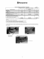 7
7
-
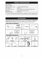 8
8
-
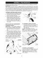 9
9
-
 10
10
-
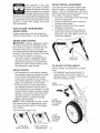 11
11
-
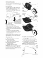 12
12
-
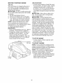 13
13
-
 14
14
-
 15
15
-
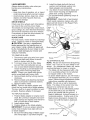 16
16
-
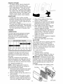 17
17
-
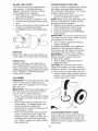 18
18
-
 19
19
-
 20
20
-
 21
21
-
 22
22
-
 23
23
-
 24
24
-
 25
25
-
 26
26
-
 27
27
-
 28
28
-
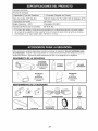 29
29
-
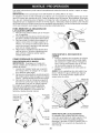 30
30
-
 31
31
-
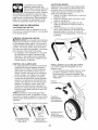 32
32
-
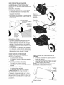 33
33
-
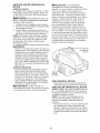 34
34
-
 35
35
-
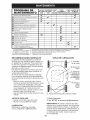 36
36
-
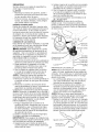 37
37
-
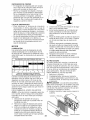 38
38
-
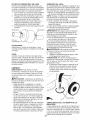 39
39
-
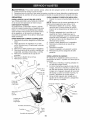 40
40
-
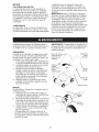 41
41
-
 42
42
-
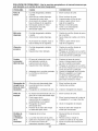 43
43
-
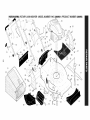 44
44
-
 45
45
-
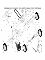 46
46
-
 47
47
-
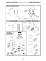 48
48
-
 49
49
-
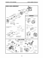 50
50
-
 51
51
-
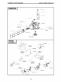 52
52
-
 53
53
-
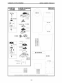 54
54
-
 55
55
-
 56
56


Husqvarna 917380961 El manual del propietario
- Categoría
- Cortadoras de césped
- Tipo
- El manual del propietario
En otros idiomas
- English: Husqvarna 917380961 Owner's manual