SilverStone ML06 El manual del propietario
- Categoría
- Cajas de la computadora
- Tipo
- El manual del propietario
Este manual también es adecuado para
La página se está cargando...
La página se está cargando...
La página se está cargando...
La página se está cargando...

1.
2.
先用螺絲起子鬆開三顆螺絲,再取下上蓋板.
鬆開中支架2顆螺絲,卸下中支架
松开中支架2颗螺丝,卸下中支架
先用螺丝起子松开三颗螺丝,再取下上盖板.
简体中文
繁體中文
简体中文
繁體中文
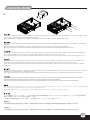
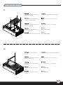
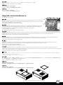
Unscrew the three screws from the
rear of the chassis then remove the
top cover.
Отвинтите три винта с задней части
корпуса, затем снимите верхнюю
крышку.
.
Lösen Sie die drei Schrauben von
der Rückseite des Gehäuses,
entfernen Sie dann die obere
Abdeckung.
케이스 뒷편의 3개의 나사를 풀은뒤
상부 커버를 제거합니다.
Dévissez les trois vis à l'arrière de
boîtier et ensuite retirez le panneau
supérieur.
Destornille los tres tornillos de la
parte posterior del chasis y luego
retire la cubierta superior.
ケースの後ろからネジ3本を外し、
それから上部カバーを取り外します。
Svitare le tre viti sul retro dello
chassis per rimuovere il cover
superiore.
Unscrew two screws from the
center brace to remove it.
Отвинтите два винта с центральной
скобы, чтобы снять ее.
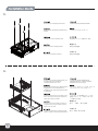
Unscrew screws from the hard
drive bracket to remove it.
Отвинтите винты с держателя
жесткого диска, чтобы снять его.
Lösen Sie die Schrauben der
Festplattenhalterung,
entfernen Sie sie.
하드 드라이브 브라켓을 제거하기 위해
나사를 제거합니다.
Dévissez les vis du casier à disques
durs pour le retirer.
Quite los tornillos del bracket del
disco duro para retirarlo.
ハードドライブブラケットのネジを
外して、取り外します。
Svitare le viti del supporto hard
drive per rimuoverlo.
Lösen Sie die beiden Schrauben
von der mittleren Verstärkung,
nehmen Sie sie heraus.
중심 브레이스에서 두개의 나사를
풀어 제거합니다.
.
Dévissez les deux vis fixant la barre
centrale pour la retirer.
Destornille los dos tornillos del
soporte central para retirarlo.
センターブレースからネジ2本を外して、
取り外します。
Svitare le due viti dal sostegno
centrale per rimuoverlo.
3.
鬆開硬碟架螺絲,卸下硬碟架
松开硬盘架螺丝,卸下硬盘架
简体中文
繁體中文
3

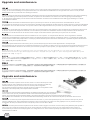
4.
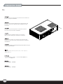
安裝電源供應器,請注意此機殼的正反裝設計, 如果使用銀欣的SFX電源,8cm風扇請朝上(關於電源供應器長度規格,請參考元件尺寸限制)
ケースに電源をインストールします。ケースは2つの異なる方向での電源設置をサポートしていることにご注意ください。SilverStone製SFX電源を
使用される場合、80mmファンを上向きに装着してください。
(電源サイズ制限の詳細については、後のページに記載のコンポーネントガイドをご参照ください。)
파워 서플라이를 케이스에 설치합니다. 이 케이스는 파워 서플라이를 두개의 방향을 설치 가능합니다. SilverStone의 SFX 전원 공급장치를 설치할
경우, 80mm 팬이 위를 향하도록 하여 전원 공급장치를 설치해야 합니다.
(만약 파워 서플라이의 크기 및 제한에 대한 자세한 정보를 확인하려면, 뒤에 나오는 부품 가이드를 참조 바랍니다. )
安装电源供应器,请注意此机壳的正反装设计, 如果使用银欣的SFX电源,8cm风扇请朝上(关于电源供应器长度规格,请参考组件尺寸限制)
简体中文
繁體中文
Install power supply into the case. Please note the case supports mounting power supply in two different orientations. If you use SilverStone’s SFX
power supply, you must install it with the 80mm fan facing up.
(For more information regarding power supply size limitations, please refer to the component guide in later pages)
Installieren Sie das Netzteil im Gehäuse. Bitte beachten Sie, dass das Gehäuse die Montage des Netzteils in zwei verschiedenen Ausrichtungen
unterstützt.
Wenn Sie SilverStones SFX-Netzteil verwenden, müssen Sie dieses mit dem 80-mm-Lüfter nach oben installieren.
(Weitere Informationen zur Beschränkung der Netzteilgröße entnehmen Sie bitte der Komponentenanleitung weiter hinten)
Installez l'alimentation dans le boîtier. Veuillez noter que le boîtier permet le montage des alimentations dans les deux sens.Si vous utilisez une
source d'alimentation SIlverStone SFX, vous devez l'installer avec le ventilateur de 80 mm face vers le haut.
(Pour plus d'informations sur les limitations des tailles des alimentations, veuillez-vous référer au guide des composant dans les pages à venir)
Instale la fuente de alimentación en la carcasa. Por favor, tenga en cuenta que la carcasa monta la fuentes de alimentación orientada de dos
modos distintos. Si usa la fuente de alimentación SFX de SilverStone, deberá instalarla con el ventilador de 80mm hacia arriba.
(Para más información sobre las limitaciones de tamaño de la fuente de alimentación, consulte por favor la guía de componentes en páginas
posteriores).
Installare l’alimentatore nel case. L’alimentatore può essere orientato in due modi differenti.Se si usa l’alimentatore SFX SilverStone, è necessario
installarlo con la ventola da 80 mm rivolta verso l'alto.
(per maggiori informazioni in merito alle limitazioni di misura degli alimentatori, fate riferimento a quanto esposto nelle pagine successive)
Установите источник питания в корпус. Обратите внимание, что можно установить источник питания в двух разных направлениях.При использовании
блока питания SilverStone SFX 80mm вентилятор охлаждения следует установить лицевой стороной вверх.
(для получения дополнительной информации относительно ограничений размера источников питания см.
руководство к компонентам далее).
4

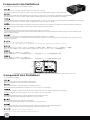
5.
6.
拆卸多功能磁架
拆卸多功能磁架
简体中文
繁體中文
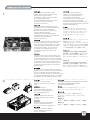
Remove the multipurpose bracket. Снимите многоцелевой кронштейн.
Nehmen Sie die Mehrzweckhalterung
heraus.
다목적 브래킷을 분리합니다.
Retirez le crochet multifonction.
Retire el bracket multipropósito.
多目的ブラケットを取り外します。
Rimuovere la staffa multiuso.
塞入I / O彈片,裝入主機板
塞入I/O弹片,装入主机板
简体中文
繁體中文
Insert the I/O shield included with your
motherboard, then install the
motherboard into the case.
Установите панель ввода/вывода
материнской платы, затем установите
материнскую плату в корпус.
Bringen Sie die bei Ihrem Motherboard
mitgelieferte Anschlussblende an,
installieren Sie dann das Motherboard
im Gehäuse.
메인보드와 동봉된 I/O 커버를 삽입한 후,
메인보드를 케이스에 설치합니다.
Insérez la plaque des ports E/S inclus
avec votre carte mère, puis mettez la
carte mère dans le boîtier.
Inserte el escudo de E/S incluido con
su placa base, luego instale la placa
base en la carcasa.
マザーボードに付属のI/Oシールドを
装着してから、ケース内にマザーボー
ドを取り付けます。
Installate il pannello I/O della scheda
madre, quindi la scheda madre stessa.
5
La página se está cargando...

9.
7
移除介面卡檔片,安裝介面卡Instale y fije las tarjetas de expansión
necesarias.
移除适配卡档片,安装适配卡
简体中文
繁體中文
Install and secure required expansion
cards.
Установите и закрепите необходимые платы расширения.
Installieren und befestigen Sie die
erforderlichen Erweiterungskarten.
필요한 확장카드를 설치하고 고정시킵니다.
.
Installez et fixez les cartes
d'extension requises.
必要とされる拡張カードをインストールし、
固定します。
Installare ed assicurare le schede
di espansione necessarie.
10.
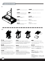
Depending on requirement, install either
slim optical drive, a 3.5” hard drive,
two 2.5” hard drive, or a 120mm fan onto
the multipurpose bracket. Remember to
install rubber padding for the fan.
В зависимости от требований установите на
многоцелевой кронштейн тонкий оптический привод,
3,5-дюймовый жесткий диск, два 2,5-дюймовых жестких
диска или 120-мм вентилятор. Не забудьте установить
резиновые прокладки для вентилятора.
Installieren Sie je nach Bedarf entweder ein
optisches Slim-Laufwerk, eine 3,5-Zoll-Festplatte,
zwei 2,5-Zoll Festplatten oder einen
120-mm-Lüfter in der Mehrzweckhalterung.
Vergessen Sie bei der Lüfterinstallation die
Gummipolster nicht.
Suivant les besoins, installez soit le disque
optique mince, un disque dur de 3,5”, deux disques
durs de 2,5”, ou un ventilateur de 120 mm sur le
crochet multifonction. Rappelez-vous d'installer le
coussinet en caoutchouc pour le ventilateur.
視需求,安裝薄型光碟機,3.5”硬碟 2.5”
硬碟,或是風扇到多功能磁架上,安裝風扇
請記得額外安裝橡膠墊片
视需求,安装薄型光驱,3.5”硬盘 2.5”硬盘,
或是风扇到多功能磁架上,安装风扇请记得额
外安装橡胶垫片
简体中文
繁體中文
요구사항에 따라 슬림형 광드라이브,
1개의 3.5” 하드 드라이브, 2개의 2.5”
하드 드라이브 또는 1개의 120mm 팬을
다목적 브래킷에 설치합니다. 반드시 고무
패딩을 팬에 설치하십시오.
必要に応じてスリム光学ドライブ、3.5”
ハードディスクドライブ1台、2.5”ハード
ディスクドライブ2台または120mmファンが
多目的ブラケットに装着可能です。ファン
にはゴムパッドの装着をお忘れなく。
Dependiendo de los requisitos, instale bien
un dispositivo óptico delgado, un disco duro de 3,5”,
dos discos duros de 2,5” ó un ventilador de 120mm
en el bracket multipropósito. Recuerde instalar la
almohadilla de goma para el ventilador.
In base alle necessità, installare sulla staffa multiuso
una unità ottica slim, un disco rigido da 3,5”,
2 dischi rigidi da 2,5”, oppure una ventola da 120 mm.
Ricordarsi di installare l’imbottitura di gomma per
la ventola.

8
11.
12.
將多功能磁架裝回機殼Reinstale el bracket multipropósito
de nuevo en el chasis.
将多功能磁架装回机壳
简体中文
繁體中文
Reinstall the multipurpose bracket
back into the chassis.
Установите многоцелевой кронштейн в корпус.
Bauen Sie die Mehrzweckhalterung
wieder in das Gehäuse ein.
다목적 브래킷을 섀시에 도로 설치합니다.
.
Réinstallez le crochet multifonction
à l'arrière du châssis.
多目的ブラケットをケースに戻します。
Reinstallare la staffa multiuso nel telaio.
將中支架裝回機殼
Reinstale el soporte central en la
carcasa.
将中支架装回机壳
简体中文
繁體中文
Reinstall center brace back into
the case.
Установите центральную скобу обратно в корпус.
Bringen Sie die mittlere Verstärkung
wieder im Gehäuse an.
중심 브레이스를 케이스에 재 설치합니다.
.
Réinstallez la barre centrale dans
le boîtier.
ケースにセンターブレースを戻します。
Reinstallare il sostegno centrale
nel case.

13.
Vuelva a poner la cubierta superior en la carcasa y
fíjela con tres tornillos para completar la instalación.
Place the top cover back onto the case and secure with three
screws to complete installation.
Platzieren Sie die obere Abdeckung auf dem Gehäuse und
befestigen Sie sie zum Abschluss der Installation mit drei
Schrauben.
Remettez le panneau supérieur sur le boîtier et fixez le
avec trois vis pour terminer l'installation.
將上蓋裝回機殼,完成組裝.
将上盖装回机壳,完成组装.
简体中文
简体
中文
繁體
體
中文
繁
中文
Завершите установку, установив верхнюю крышку обратно на корпус
и закрепив тремя винтами.
상부 커버를 케이스에 재 장착후 3개의 나사로 고정시켜
설치를 마칩니다.
ケースに上部カバーを戻し、3つのネジ3本で固定すると、
インストールは完成です。
Riposizionare quindi il cover superiore ed assicurarlo allo
chassis con le tre viti rimosse in precedenza per completare
l’installazione.
9
La página se está cargando...

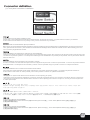
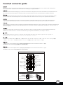
Connector definition
Please refer to the motherboard manuals for the motherboard’s “Front Panel Connector ” or “System Panel Connector” pin definition.;
the white/black wires are negative while other colors are positive wires. The Power LED wires are separate pins for compatibility with different
motherboard so please make sure they are connected in the right polarity by referring to your motherboard manual.
:
Описание контактов разъемов приведены в разделах “Разъемы передней панели” или “Разъемы системной панели” руководства
пользователя материнской платы. Белые/черный провода - отрицательной полярности, цветные провода - положительной полярности.
Провода светодиодного индикатора питания имеют отдельные контакты для совместимости с различными типами контактов материнских
плат, поэтому обратитесь к руководству пользователя материнской платы
и убедитесь, что полярность соблюдена.
Bitte suchen Sie in der Motherboard-Dokumentation nach der Pinbelegung der Anschlüsse des Frontbedienfeldes („Front Panel Connectors“ oder „
System Panel Connectors“). Die weißen/ schwarz Adern sind negativ (-), die farbigen Adern positiv (+).Die Kabel für die Betriebsanzeige-LED
sind zur Kompatibilität mit unterschiedlichsten Motherboards einzeln, nicht als kompletter Stecker ausgeführt. Achten Sie hier bitte auf die richtige
Polarität, lesen Sie in der Dokumentation Ihres Motherboards nach.
Veuillez-vous référer au manuel de votre carte mère pour la description des broches "des connecteurs du panneau frontal" et des broches "des
connecteurs du panneau système". Les câbles colorés en blanc/noir sont négatifs alors que ceux d'une autre couleur sont positifs. Les câbles de
la LED Power sont séparés afin d'être compatible avec différentes cartes mères, donc vérifiez bien qu'ils sont branchés avec la bonne polarité en
vous référant au manuel de votre carte mère
Por favor, consulte en los manuales de la placa base la configuración de pines del “Conector de panel frontal” ó “Conector de panel de sistema”
de su placa base. Los cables de color blanco/negro son negativos mientras que los de color son positivos. Los cables LED de potencia tienen
pines separados para compatibilidad con diferentes definiciones de pines de la placa base luego por favor, asegúrese de que están conectados
en la polaridad correcta consultando el manual de su placa base.
Fare riferimento al manuale della scheda madre nella sezione “Connettori del pannello frontale” o “Connettori del pannello di sistema”. I cavi di
colore bianco/nero sono il polo negativo, mentre quelli di colore diverso il positivo.
메인보드 매뉴얼의 전면패널 커넥터 혹은 시스템패널 커넥터 핀을 참조하기 바랍니다. 하얀/검은선의 경우 음극이며, 다른 색의 경우
양극입니다. 파워 LED 선은 분리되어 다양한 메인보드에서 동작할 수 있도록 되어 있습니다. 그러므로 메인보드 매뉴얼을 참조하여 올바를
극성을 주의해 선택하시기 바랍니다.
マザーボードの「フロントパネルコネクタ」または「システムパネルコネクタ」ピン配列についてはマザーボードマニュアルを参照してください。
白/黑色のリード線はマイナスで、色の着いたリード線がプラスです。電源LEDリード線は種々のマザーボードピン定義と互換性を持たせるため
分離されたピンとなっているので、ご使用のマザーボードマニュアルを参照して、適切な極性に接続されるようお確かめください。
請參考主機說明書的Front Panel Connectors安裝Pin Define,將Connector插上; 白/黑色線的部分為負極,彩色線的部分是正極。Power LED為
了適應各主機板的不同, 特別設計為散Pin樣式,請安心使用。
请参考说明书的Front Panel Connectors安装Pin Define,将Connector插上;白/黑色线的部份为负极,彩色线的部份为正极。Power LED为了适应
主机板的不同, 特别设计为散Pin样式,请安心使用。
11
La página se está cargando...
La página se está cargando...

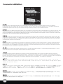
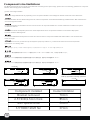
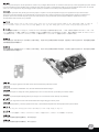
Component size limitations
The ML06 supports standard SFX power supply with a 100mm depth.
(2) Power supply limitations
Der ML06 unterstützt SFX-Standardnetzteile mit einer Tiefe von 100 mm.
Le ML06 supporte une source d'alimentation SFX standard avec une profondeur de 100mm.
La ML06 acepta fuentes de alimentación SFX estándar con una profundidad de 100mm.
ML06 supporta l’alimentatore standard SFX con una profondità di 100 mm.
Корпус ML06 совместим со стандартными блоками питания SFX глубиной 100 мм.
ML06限定使用長度為100mm的標準SFX電源
ML06限定使用长度为100mm的标准SFX电源
35.6
34
28
102
130
120.0
18.7
138.7
ML06は標準SFX電源(100㎜深)に対応しています。
ML06는 100mm 깊이의 표준 SFX 전원 공급장치를 지원합니다.
Please note 3.5” hard drive and 120mm x 25mm fan are thicker and might interfere with USB 3.0 connector.
1
2
3
14
La página se está cargando...
La página se está cargando...
La página se está cargando...
La página se está cargando...

1. Используйте шестигранную отвертку для снятия разъема стандартного размера графической карты.
2. Сделайте паз VGA (D-sub) в корпусе и установите разъем VGA (D-sub).
Паз в корпусе позволит установить разъем в обоих направлениях, поэтому можно выбрать необходимый вариант в зависимости от
графической карты.
1. 準備六角套筒起子,將顯示卡上原本的VGA插座拆下
2. 扭開機殼上的不斷孔,將VGA插座裝上去;機殼上的孔位是配合各種不同的顯示卡,可以正反安裝,請根據您的顯示卡需求,選一種最好的方向安裝。
1. 准备六角套筒起子,将显示卡上原本的VGA插座拆下
2. 扭开机壳上的不断孔,将VGA插座装上去;机壳上的孔位是配合各种不同的显示卡,可以正反安装,请根据您的显示卡需求,选一种最好的方向安装。
1. 六角ドライバーで、標準サイズのスロットをグラフィックカードから取り外します。
2. ケースからVGA(D-sub)開口部を開け、VGA(D-sub)コネクタをインストールします。
ケースの開口部は両方の方向のコネクタ設置をサポートするので、グラフィックカードの必要条件に最適な向きを選ぶことができます。
1. 육각 드라이버를 이용해, 일반적인 크기의 슬롯을 그래픽 카드에서 제거합니다.
2. VGA(D-SUB)가 있는 곳의 철판을 제거해, VGA(D-SUB) 커넥터를 설치합니다.
케이스의 구멍은 커넥터 마운팅을 양쪽방향에서 모두 지원하기 때문에 그래픽 카드에 맞는 적절한 방향으로 설치 바랍니다.
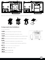
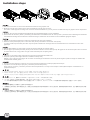
Installation steps
1. Use a hex screwdriver to remove the standard sized slot from the graphics card.
2. Break the VGA (D-sub) cutout from the case and install the VGA (D-sub) connector.
The case’s cutout supports mounting of the connector in both orientations so you may choose one that best suit your graphics card’s requirement.
1. Entfernen Sie mit einem Sechskantschraubendreher den Standardsteckplatz von der Grafikkarte.
2. Durchstoßen Sie die VGA- (D-Sub-) Ausfräsung des Gehäuses und installieren Sie den VGA- (D-Sub-) Anschluss. Die Ausfräsung des Gehäuses
unterstützt die Montage des Anschlusses in beide Richtungen; wählen Sie die am besten für Ihre Grafikkarte geeignete Option.
1. Utilisez un tournevis hexagonal pour retirer les emplacements de la carte graphique.
2. Retirer le cache prédécoupé pour le connecteur VGA (D-sub) et installez le connecteur VGA (D-sub).
Le cache prédécoupé du boîtier peut subir n’importe quelle orientation de montage selon les nécessités dues aux contraintes de votre carte
graphique.
1. Use un destornillador hex para quitar el zócalo de tamaño estándar de la tarjeta gráfica.
2. Abra el agujero precortado para VGA (D-sub) de la carcasa e instale el conector VGA (D-sub). El agujero de la carcasa acepta montar el conector
en ambas direcciones, luego podría escoger la más adecuada para su tarjeta gráfica.
1. Utilizzare un cacciavite a testa esagonale per rimuovere la staffa standard dalla VGA.
2. Rompere il (D-sub) VGA ritaglio dal caso e installare il VGA (D-sub).
Ritaglio Il caso supporta il montaggio del connettore in entrambi gli orientamenti in modo da potete scegliere quella che meglio si adattano alle
necessità della scheda grafica.
19
La página se está cargando...
La página se está cargando...
La página se está cargando...
Transcripción de documentos
1. Unscrew the three screws from the rear of the chassis then remove the top cover. Отвинтите три винта с задней части корпуса, затем снимите верхнюю крышку.. Lösen Sie die drei Schrauben von der Rückseite des Gehäuses, entfernen Sie dann die obere Abdeckung. 케이스 뒷편의 3개의 나사를 풀은뒤 상부 커버를 제거합니다. Dévissez les trois vis à l'arrière de boîtier et ensuite retirez le panneau supérieur. ケースの後ろからネジ3本を外し、 それから上部カバーを取り外します。 Destornille los tres tornillos de la parte posterior del chasis y luego retire la cubierta superior. 先用螺絲起子鬆開三顆螺絲,再取下上蓋板. Svitare le tre viti sul retro dello chassis per rimuovere il cover superiore. 先用螺丝起子松开三颗螺丝,再取下上盖板. Unscrew two screws from the center brace to remove it. Отвинтите два винта с центральной скобы, чтобы снять ее. Lösen Sie die beiden Schrauben von der mittleren Verstärkung, nehmen Sie sie heraus. 중심 브레이스에서 두개의 나사를 풀어 제거합니다.. Dévissez les deux vis fixant la barre centrale pour la retirer. センターブレースからネジ2本を外して、 取り外します。 Destornille los dos tornillos del soporte central para retirarlo. 鬆開中支架2顆螺絲,卸下中支架 Svitare le due viti dal sostegno centrale per rimuoverlo. 松开中支架2颗螺丝,卸下中支架 Unscrew screws from the hard drive bracket to remove it. Отвинтите винты с держателя жесткого диска, чтобы снять его. Lösen Sie die Schrauben der Festplattenhalterung, entfernen Sie sie. 하드 드라이브 브라켓을 제거하기 위해 나사를 제거합니다. Dévissez les vis du casier à disques durs pour le retirer. ハードドライブブラケットのネジを 外して、取り外します。 Quite los tornillos del bracket del disco duro para retirarlo. 鬆開硬碟架螺絲,卸下硬碟架 Svitare le viti del supporto hard drive per rimuoverlo. 松开硬盘架螺丝,卸下硬盘架 繁體中文 简体中文 2. 繁體中文 简体中文 3. 繁體中文 简体中文 3 4. Install power supply into the case. Please note the case supports mounting power supply in two different orientations. If you use SilverStone’s SFX power supply, you must install it with the 80mm fan facing up. (For more information regarding power supply size limitations, please refer to the component guide in later pages) Installieren Sie das Netzteil im Gehäuse. Bitte beachten Sie, dass das Gehäuse die Montage des Netzteils in zwei verschiedenen Ausrichtungen unterstützt. Wenn Sie SilverStones SFX-Netzteil verwenden, müssen Sie dieses mit dem 80-mm-Lüfter nach oben installieren. (Weitere Informationen zur Beschränkung der Netzteilgröße entnehmen Sie bitte der Komponentenanleitung weiter hinten) Installez l'alimentation dans le boîtier. Veuillez noter que le boîtier permet le montage des alimentations dans les deux sens.Si vous utilisez une source d'alimentation SIlverStone SFX, vous devez l'installer avec le ventilateur de 80 mm face vers le haut. (Pour plus d'informations sur les limitations des tailles des alimentations, veuillez-vous référer au guide des composant dans les pages à venir) Instale la fuente de alimentación en la carcasa. Por favor, tenga en cuenta que la carcasa monta la fuentes de alimentación orientada de dos modos distintos. Si usa la fuente de alimentación SFX de SilverStone, deberá instalarla con el ventilador de 80mm hacia arriba. (Para más información sobre las limitaciones de tamaño de la fuente de alimentación, consulte por favor la guía de componentes en páginas posteriores). Installare l’alimentatore nel case. L’alimentatore può essere orientato in due modi differenti.Se si usa l’alimentatore SFX SilverStone, è necessario installarlo con la ventola da 80 mm rivolta verso l'alto. (per maggiori informazioni in merito alle limitazioni di misura degli alimentatori, fate riferimento a quanto esposto nelle pagine successive) Установите источник питания в корпус. Обратите внимание, что можно установить источник питания в двух разных направлениях.При использовании блока питания SilverStone SFX 80mm вентилятор охлаждения следует установить лицевой стороной вверх. (для получения дополнительной информации относительно ограничений размера источников питания см. руководство к компонентам далее). 파워 서플라이를 케이스에 설치합니다. 이 케이스는 파워 서플라이를 두개의 방향을 설치 가능합니다. SilverStone의 SFX 전원 공급장치를 설치할 경우, 80mm 팬이 위를 향하도록 하여 전원 공급장치를 설치해야 합니다. (만약 파워 서플라이의 크기 및 제한에 대한 자세한 정보를 확인하려면, 뒤에 나오는 부품 가이드를 참조 바랍니다. ) ケースに電源をインストールします。ケースは2つの異なる方向での電源設置をサポートしていることにご注意ください。SilverStone製SFX電源を 使用される場合、80mmファンを上向きに装着してください。 (電源サイズ制限の詳細については、後のページに記載のコンポーネントガイドをご参照ください。) 繁體中文 安裝電源供應器,請注意此機殼的正反裝設計, 如果使用銀欣的SFX電源,8cm風扇請朝上(關於電源供應器長度規格,請參考元件尺寸限制) 简体中文 安装电源供应器,请注意此机壳的正反装设计, 如果使用银欣的SFX电源,8cm风扇请朝上(关于电源供应器长度规格,请参考组件尺寸限制) 4 5. Remove the multipurpose bracket. Nehmen Sie die Mehrzweckhalterung heraus. Снимите многоцелевой кронштейн. 다목적 브래킷을 분리합니다. Retirez le crochet multifonction. 多目的ブラケットを取り外します。 Retire el bracket multipropósito. 拆卸多功能磁架 Rimuovere la staffa multiuso. 拆卸多功能磁架 Insert the I/O shield included with your motherboard, then install the motherboard into the case. Установите панель ввода/вывода материнской платы, затем установите материнскую плату в корпус. Bringen Sie die bei Ihrem Motherboard mitgelieferte Anschlussblende an, installieren Sie dann das Motherboard im Gehäuse. 메인보드와 동봉된 I/O 커버를 삽입한 후, 메인보드를 케이스에 설치합니다. Insérez la plaque des ports E/S inclus avec votre carte mère, puis mettez la carte mère dans le boîtier. マザーボードに付属のI/Oシールドを 装着してから、ケース内にマザーボー ドを取り付けます。 Inserte el escudo de E/S incluido con su placa base, luego instale la placa base en la carcasa. 塞入I / O彈片,裝入主機板 Installate il pannello I/O della scheda madre, quindi la scheda madre stessa. 塞入I/O弹片,装入主机板 繁體中文 简体中文 6. 繁體中文 简体中文 5 9. Install and secure required expansion cards. Установите и закрепите необходимые платы расширения. Installieren und befestigen Sie die erforderlichen Erweiterungskarten. 필요한 확장카드를 설치하고 고정시킵니다. . Installez et fixez les cartes d'extension requises. 必要とされる拡張カードをインストールし、 固定します。 Instale y fije las tarjetas de expansión necesarias. 移除介面卡檔片,安裝介面卡 Installare ed assicurare le schede di espansione necessarie. 移除适配卡档片,安装适配卡 繁體中文 简体中文 10. Depending on requirement, install either slim optical drive, a 3.5” hard drive, two 2.5” hard drive, or a 120mm fan onto the multipurpose bracket. Remember to install rubber padding for the fan. Dependiendo de los requisitos, instale bien un dispositivo óptico delgado, un disco duro de 3,5”, dos discos duros de 2,5” ó un ventilador de 120mm en el bracket multipropósito. Recuerde instalar la almohadilla de goma para el ventilador. 요구사항에 따라 슬림형 광드라이브, 1개의 3.5” 하드 드라이브, 2개의 2.5” 하드 드라이브 또는 1개의 120mm 팬을 다목적 브래킷에 설치합니다. 반드시 고무 패딩을 팬에 설치하십시오. Installieren Sie je nach Bedarf entweder ein optisches Slim-Laufwerk, eine 3,5-Zoll-Festplatte, zwei 2,5-Zoll Festplatten oder einen 120-mm-Lüfter in der Mehrzweckhalterung. Vergessen Sie bei der Lüfterinstallation die Gummipolster nicht. In base alle necessità, installare sulla staffa multiuso una unità ottica slim, un disco rigido da 3,5”, 2 dischi rigidi da 2,5”, oppure una ventola da 120 mm. Ricordarsi di installare l’imbottitura di gomma per la ventola. 必要に応じてスリム光学ドライブ、3.5” ハードディスクドライブ1台、2.5”ハード ディスクドライブ2台または120mmファンが 多目的ブラケットに装着可能です。ファン にはゴムパッドの装着をお忘れなく。 Suivant les besoins, installez soit le disque optique mince, un disque dur de 3,5”, deux disques durs de 2,5”, ou un ventilateur de 120 mm sur le crochet multifonction. Rappelez-vous d'installer le coussinet en caoutchouc pour le ventilateur. В зависимости от требований установите на многоцелевой кронштейн тонкий оптический привод, 3,5-дюймовый жесткий диск, два 2,5-дюймовых жестких диска или 120-мм вентилятор. Не забудьте установить резиновые прокладки для вентилятора. 視需求,安裝薄型光碟機,3.5”硬碟 2.5” 硬碟,或是風扇到多功能磁架上,安裝風扇 請記得額外安裝橡膠墊片 繁體中文 简体中文 视需求,安装薄型光驱,3.5”硬盘 2.5”硬盘, 或是风扇到多功能磁架上,安装风扇请记得额 外安装橡胶垫片 7 11. Reinstall the multipurpose bracket back into the chassis. Установите многоцелевой кронштейн в корпус. Bauen Sie die Mehrzweckhalterung wieder in das Gehäuse ein. 다목적 브래킷을 섀시에 도로 설치합니다. . Réinstallez le crochet multifonction à l'arrière du châssis. 多目的ブラケットをケースに戻します。 Reinstale el bracket multipropósito de nuevo en el chasis. 將多功能磁架裝回機殼 繁體中文 简体中文 Reinstallare la staffa multiuso nel telaio. 将多功能磁架装回机壳 12. Reinstall center brace back into the case. Установите центральную скобу обратно в корпус. Bringen Sie die mittlere Verstärkung wieder im Gehäuse an. 중심 브레이스를 케이스에 재 설치합니다. . Réinstallez la barre centrale dans le boîtier. ケースにセンターブレースを戻します。 Reinstale el soporte central en la carcasa. 將中支架裝回機殼 Reinstallare il sostegno centrale nel case. 将中支架装回机壳 繁體中文 简体中文 8 13. Place the top cover back onto the case and secure with three screws to complete installation. Platzieren Sie die obere Abdeckung auf dem Gehäuse und befestigen Sie sie zum Abschluss der Installation mit drei Schrauben. Remettez le panneau supérieur sur le boîtier et fixez le avec trois vis pour terminer l'installation. Vuelva a poner la cubierta superior en la carcasa y fíjela con tres tornillos para completar la instalación. Riposizionare quindi il cover superiore ed assicurarlo allo chassis con le tre viti rimosse in precedenza per completare l’installazione. Завершите установку, установив верхнюю крышку обратно на корпус и закрепив тремя винтами. 상부 커버를 케이스에 재 장착후 3개의 나사로 고정시켜 설치를 마칩니다. ケースに上部カバーを戻し、3つのネジ3本で固定すると、 インストールは完成です。 繁體 繁 體 中文 將上蓋裝回機殼,完成組裝. 简体中文 将上盖装回机壳,完成组装. 9 Connector definition Please refer to the motherboard : manuals for the motherboard’s “Front Panel Connector ” or “System Panel Connector” pin definition.; the white/black wires are negative while other colors are positive wires. The Power LED wires are separate pins for compatibility with different motherboard so please make sure they are connected in the right polarity by referring to your motherboard manual. Bitte suchen Sie in der Motherboard-Dokumentation nach der Pinbelegung der Anschlüsse des Frontbedienfeldes („Front Panel Connectors“ oder „ System Panel Connectors“). Die weißen/ schwarz Adern sind negativ (-), die farbigen Adern positiv (+).Die Kabel für die Betriebsanzeige-LED sind zur Kompatibilität mit unterschiedlichsten Motherboards einzeln, nicht als kompletter Stecker ausgeführt. Achten Sie hier bitte auf die richtige Polarität, lesen Sie in der Dokumentation Ihres Motherboards nach. Veuillez-vous référer au manuel de votre carte mère pour la description des broches "des connecteurs du panneau frontal" et des broches "des connecteurs du panneau système". Les câbles colorés en blanc/noir sont négatifs alors que ceux d'une autre couleur sont positifs. Les câbles de la LED Power sont séparés afin d'être compatible avec différentes cartes mères, donc vérifiez bien qu'ils sont branchés avec la bonne polarité en vous référant au manuel de votre carte mère Por favor, consulte en los manuales de la placa base la configuración de pines del “Conector de panel frontal” ó “Conector de panel de sistema” de su placa base. Los cables de color blanco/negro son negativos mientras que los de color son positivos. Los cables LED de potencia tienen pines separados para compatibilidad con diferentes definiciones de pines de la placa base luego por favor, asegúrese de que están conectados en la polaridad correcta consultando el manual de su placa base. Fare riferimento al manuale della scheda madre nella sezione “Connettori del pannello frontale” o “Connettori del pannello di sistema”. I cavi di colore bianco/nero sono il polo negativo, mentre quelli di colore diverso il positivo. Описание контактов разъемов приведены в разделах “Разъемы передней панели” или “Разъемы системной панели” руководства пользователя материнской платы. Белые/черный провода - отрицательной полярности, цветные провода - положительной полярности. Провода светодиодного индикатора питания имеют отдельные контакты для совместимости с различными типами контактов материнских плат, поэтому обратитесь к руководству пользователя материнской платы и убедитесь, что полярность соблюдена. 메인보드 매뉴얼의 전면패널 커넥터 혹은 시스템패널 커넥터 핀을 참조하기 바랍니다. 하얀/검은선의 경우 음극이며, 다른 색의 경우 양극입니다. 파워 LED 선은 분리되어 다양한 메인보드에서 동작할 수 있도록 되어 있습니다. 그러므로 메인보드 매뉴얼을 참조하여 올바를 극성을 주의해 선택하시기 바랍니다. マザーボードの「フロントパネルコネクタ」または「システムパネルコネクタ」ピン配列についてはマザーボードマニュアルを参照してください。 白/黑色のリード線はマイナスで、色の着いたリード線がプラスです。電源LEDリード線は種々のマザーボードピン定義と互換性を持たせるため 分離されたピンとなっているので、ご使用のマザーボードマニュアルを参照して、適切な極性に接続されるようお確かめください。 請參考主機說明書的Front Panel Connectors安裝Pin Define,將Connector插上; 白/黑色線的部分為負極,彩色線的部分是正極。Power LED為 了適應各主機板的不同, 特別設計為散Pin樣式,請安心使用。 请参考说明书的Front Panel Connectors安装Pin Define,将Connector插上;白/黑色线的部份为负极,彩色线的部份为正极。Power LED为了适应 主机板的不同, 特别设计为散Pin样式,请安心使用。 11 35.6 120.0 34 28 102 18.7 138.7 130 Please note 3.5” hard drive and 120mm x 25mm fan are thicker and might interfere with USB 3.0 connector. 3 1 2 Component size limitations (2) Power supply limitations The ML06 supports standard SFX power supply with a 100mm depth. Der ML06 unterstützt SFX-Standardnetzteile mit einer Tiefe von 100 mm. Le ML06 supporte une source d'alimentation SFX standard avec une profondeur de 100mm. La ML06 acepta fuentes de alimentación SFX estándar con una profundidad de 100mm. ML06 supporta l’alimentatore standard SFX con una profondità di 100 mm. Корпус ML06 совместим со стандартными блоками питания SFX глубиной 100 мм. ML06는 100mm 깊이의 표준 SFX 전원 공급장치를 지원합니다. ML06は標準SFX電源(100㎜深)に対応しています。 ML06限定使用長度為100mm的標準SFX電源 ML06限定使用长度为100mm的标准SFX电源 14 Installation steps 1. Use a hex screwdriver to remove the standard sized slot from the graphics card. 2. Break the VGA (D-sub) cutout from the case and install the VGA (D-sub) connector. The case’s cutout supports mounting of the connector in both orientations so you may choose one that best suit your graphics card’s requirement. 1. Entfernen Sie mit einem Sechskantschraubendreher den Standardsteckplatz von der Grafikkarte. 2. Durchstoßen Sie die VGA- (D-Sub-) Ausfräsung des Gehäuses und installieren Sie den VGA- (D-Sub-) Anschluss. Die Ausfräsung des Gehäuses unterstützt die Montage des Anschlusses in beide Richtungen; wählen Sie die am besten für Ihre Grafikkarte geeignete Option. 1. Utilisez un tournevis hexagonal pour retirer les emplacements de la carte graphique. 2. Retirer le cache prédécoupé pour le connecteur VGA (D-sub) et installez le connecteur VGA (D-sub). Le cache prédécoupé du boîtier peut subir n’importe quelle orientation de montage selon les nécessités dues aux contraintes de votre carte graphique. 1. Use un destornillador hex para quitar el zócalo de tamaño estándar de la tarjeta gráfica. 2. Abra el agujero precortado para VGA (D-sub) de la carcasa e instale el conector VGA (D-sub). El agujero de la carcasa acepta montar el conector en ambas direcciones, luego podría escoger la más adecuada para su tarjeta gráfica. 1. Utilizzare un cacciavite a testa esagonale per rimuovere la staffa standard dalla VGA. 2. Rompere il (D-sub) VGA ritaglio dal caso e installare il VGA (D-sub). Ritaglio Il caso supporta il montaggio del connettore in entrambi gli orientamenti in modo da potete scegliere quella che meglio si adattano alle necessità della scheda grafica. 1. Используйте шестигранную отвертку для снятия разъема стандартного размера графической карты. 2. Сделайте паз VGA (D-sub) в корпусе и установите разъем VGA (D-sub). Паз в корпусе позволит установить разъем в обоих направлениях, поэтому можно выбрать необходимый вариант в зависимости от графической карты. 1. 육각 드라이버를 이용해, 일반적인 크기의 슬롯을 그래픽 카드에서 제거합니다. 2. VGA(D-SUB)가 있는 곳의 철판을 제거해, VGA(D-SUB) 커넥터를 설치합니다. 케이스의 구멍은 커넥터 마운팅을 양쪽방향에서 모두 지원하기 때문에 그래픽 카드에 맞는 적절한 방향으로 설치 바랍니다. 1. 六角ドライバーで、標準サイズのスロットをグラフィックカードから取り外します。 2. ケースからVGA(D-sub)開口部を開け、VGA(D-sub)コネクタをインストールします。 ケースの開口部は両方の方向のコネクタ設置をサポートするので、グラフィックカードの必要条件に最適な向きを選ぶことができます。 1. 準備六角套筒起子,將顯示卡上原本的VGA插座拆下 2. 扭開機殼上的不斷孔,將VGA插座裝上去;機殼上的孔位是配合各種不同的顯示卡,可以正反安裝,請根據您的顯示卡需求,選一種最好的方向安裝。 1. 准备六角套筒起子,将显示卡上原本的VGA插座拆下 2. 扭开机壳上的不断孔,将VGA插座装上去;机壳上的孔位是配合各种不同的显示卡,可以正反安装,请根据您的显示卡需求,选一种最好的方向安装。 19-
 1
1
-
 2
2
-
 3
3
-
 4
4
-
 5
5
-
 6
6
-
 7
7
-
 8
8
-
 9
9
-
 10
10
-
 11
11
-
 12
12
-
 13
13
-
 14
14
-
 15
15
-
 16
16
-
 17
17
-
 18
18
-
 19
19
-
 20
20
-
 21
21
-
 22
22
-
 23
23
-
 24
24


SilverStone ML06 El manual del propietario
- Categoría
- Cajas de la computadora
- Tipo
- El manual del propietario
- Este manual también es adecuado para
en otros idiomas
- français: SilverStone ML06 Le manuel du propriétaire
- italiano: SilverStone ML06 Manuale del proprietario
- English: SilverStone ML06 Owner's manual
- 日本語: SilverStone ML06 取扱説明書
Artículos relacionados
-
SilverStone Grandia GD09 Guía de instalación
-
SilverStone Grandia GD05 El manual del propietario
-
-
-
-
-
-
-
SilverStone SST-FT03S Guía de instalación
-