GE GEWADREW4651 Guía de instalación
- Categoría
- Secadoras de ropa eléctricas
- Tipo
- Guía de instalación

BEFORE YOU BEGIN
Read these instructions completely and carefully.
•
IMPORTANT – Save these instructions for local
electrical inspector’s use.
•
IMPORTANT – Observe all governing codes and
ordinances.
•
Install the clothes dryer according to the manufacturer’s
instructions and local codes.
•
Note to Installer – Be sure to leave these instructions
with the Consumer.
•
Note to Consumer – Keep these instructions for future
reference.
•
Clothes dryer installation must be performed by a
qualified installer.
•
This dryer must be exhausted to the outdoors.
•
Before the old dryer is removed from service or
discarded, remove the dryer door.
•
Service information and the wiring diagram are located
in the control console.
•
Do not allow children on or in the appliance. Close
supervision of children is necessary when the appliance
is used near children.
•
Proper installation is the responsibility of the installer.
•
Product failure due to improper installation is not
covered under the Warranty
.
• Install the dryer where the temperature is above 50°F
for satisfactory operation of the dryer control system.
• Remove and discard existing plastic or metal foil duct
and replace with UL-listed duct.
Questions? Call GE Appliances at 800.GE.CARES (800.432.2737) or visit our Web site at: GEAppliances.com
- Fire Hazard
WARNING
• Clothes dryer installation must be performed by a
qualified installer.
•
Install the clothes dryer according to these
instructions and local codes.
•
DO NOT install a clothes dryer with flexible plastic
venting materials. If flexible metal (semi-rigid or
foil-type) duct is installed, it must be UL-listed and
installed in accordance with the instructions found
in “Connecting the Dryer to House Vent” later in
this manual. Flexible venting materials are known
to collapse, be easily crushed and trap lint. These
conditions will obstruct dryer airflow and increase
the risk of fire.
•
DO NOT install or store this appliance in any
location where it could be exposed to water or
weather.
•
To reduce the risk of severe injury or death, follow
all installation instructions.
•
Save these instructions. (Installers: Be sure to leave
these instructions with the customer.)
Installation Dryers
Instructions
05
31-16775-3 12-16 GEA
Printed in Mexico
234D2318P005
IN THE COMMONWEALTH OF
MASSACHUSETTS, THE FOLLOWING
INSTALLATION INSTRUCTIONS APPLY:
• Installation must be performed by a qualified
or licensed contractor, plumber, or gasfitter
qualified or licensed by the State.
•
If using a ball valve, it shall be a T-handle type.
•
A flexible gas connector, when used, must not
exceed 3 feet.
FOR GAS DRYERS ONLY

Installation Instructions
Tilt the dryer sideways and remove the foam
shipping pads by pulling at the sides and breaking
them away from the dryer legs. Be sure to remove all
of the foam pieces around the legs.
Remove literature and bag containing accessories.
UNPACKING YOUR DRYER
STEAM WATER HOSES:
GE Appliances strongly recommends the use of factory
specified parts. These hoses are manufactured and tested to
meet GE Appliances specifications.
GE Appliances strongly recommends the use of new water
supply hoses. Hoses degrade over time and need to be
replaced every 5 years to reduce the risk of hose failures and
water damage.
Parts and Accessories
Order on-line at GEApplianceParts.com, 24 hours a day or
by phone at 800.626.2002 during normal business hours.
Part Number Accessory
WE25X20060 Complete Kit (hoses, Y-adapter
washers) (included)
OR
WE1M847 Long Hose and
WE01X22395 Short Hose
PM14X10056 Dryer door opening vent brush
(not included)
WX14X10007 LintEater™ Dryer rotary tube brush
(not included)
2
ROUGH-IN
DIMENSIONS
4 5/8”
(11.7 cm)
or
6 1/2”
(16.5 cm)
with Riser
Y
X
27”
(68.8 cm)
X
4 1/4”
(10.8 cm)
Side ViewFront View
Cubic
Foot
XY
6.2
43 3/8”
(110 cm)
26 3/4”
(68 cm)
7.2
43 3/8”
(110 cm)
29 1/2”
(75 cm)
7.4
43 3/4”
(111 cm)
30 1/2”
(78 cm)
7.4
(with
Riser)
45 1/2”
(116 cm)
30 1/2”
(78 cm)
State of California Proposition 65 Warnings
WARNING
This product contains one or more chemicals known to the State of California to cause cancer, and birth
defects or other reproductive harm.
Gas appliances can cause low-level exposure to some of these substances, including benzene, carbon monoxide, formaldehyde,
and soot, caused primarily by the incomplete combustion of natural gas or LP fuels. Exposure to these substances can be
minimized by properly venting the dryer to the outdoors.

Installation Instructions
3
MOBILE OR MANUFACTURED HOME
INSTALLATION
POWER CORDS:
GE Appliances strongly recommends the use of factory
specified parts. Select the power cord to fit your installation
requirements.
Order on-line at GEApplianceParts.com, 24 hours a day or
by phone at 800.626.2002 during normal business hours.
Part Number Type Length Amperage
WX9X2 3-Prong 4 Feet 30
WX9X3 3-Prong 5 Feet 30
WX9X4 3-Prong 6 Feet 30
WX9X18 4-Prong 4 Feet 30
WX9X19 4-Prong 5 Feet 30
WX9X20 4-Prong 6 Feet 30
• Installation MUST conform to the
MANUFACTURED HOME CONSTRUCTION AND
SAFETY STANDARD, TITLE 24, PART 32–80 or
Standard CAN/CSA-Z240 MH, or, when such
standard is not applicable, with AMERICAN
NATIONAL STANDARD FOR MOBILE HOME,
ANSI/NFPA NO. 501B.
•
The dryer MUST be vented to the outdoors.
•
The exhaust vent MUST be securely fastened to
a non-combustible portion of the mobile home.
•
The vent MUST NOT be terminated beneath a
mobile or manufactured home.
•
The vent duct material MUST BE METAL.
•
KIT 14-D346-33 MUST be used to attach the dryer
securely to the structure.
•
The vent MUST NOT be connected to any other
duct, vent or chimney.
•
DO NOT use sheet metal screws or other
fastening devices which extend into the interior
of the exhaust vent.
•
Provide an opening with a free area of at least
25 square inches for introduction of outside air
into the dryer room.
•
See the sections for electrical connection
information.
REQUIREMENTS FOR ALCOVE OR CLOSET
INSTALLATION
- Explosion Hazard
WARNING
Keep flammable materials and vapors, such as gasoline,
away from dryer.
Place dryer at least 18” (46 cm) above the floor for a
garage installation.
Failure to do so can result in death, explosion, or fire.
• The dryer MUST be vented to the outdoors. See
the EXHAUSTING THE DRYER section.
•
Minimum clearance between dryer cabinet and
adjacent walls or other surfaces is:
0” either side
1” front
1” rear
1” top
•
Consideration must be given to provide adequate
clearance for installation and service.
•
Closet doors must be louvered or otherwise
ventilated and have at least 60 square inches of
open area. If the closet contains both a washer
and a dryer, doors must contain a minimum of
120 square inches of open area.
NOTE: WHEN THE EXHAUST DUCT IS LOCATED IN
THE REAR OF THE DRYER, THE CONFIGURATION OF
THE DUCTING MAY REQUIRE GREATER THAN 1” OF
REAR CLEARANCE.
Gas Dryers Only:
•
No other fuel burning appliance shall be installed
in the same closet as a gas dryer.
•
The dryer must be disconnected from the gas
supply piping during pressure testing at pressures
greater than ½ psi (3.5 kPa).
•
A 1/8 inch NPT minimum plugged tapping,
accessible for test gauge connection, must be
installed immediately upstream of the gas supply
connection to the dryer.
MINIMUM CLEARANCE OTHER THAN
ALCOVE OR CLOSET INSTALLATION
Minimum clearance to combustible surfaces and
for air opening are: 0” both sides; 1” rear; 1” on top.
Consideration must be given to provide adequate
clearance for installation and service.

To produce steam, the dryer must connect to
the cold water supply. Since the washer must
also connect to the cold water, a “Y” connector
is inserted to allow both inlet hoses to make that
connection at the same time.
NOTE: Use the new inlet hoses provided; never use
old hoses.
1. Turn the cold water faucet off. Remove the
washer inlet hose from the washer fill valve
connector (cold).
2. Ensure the rubber flat washer is in place and
attach one female coupling of the short hose
onto the washer fill valve connector. Tighten by
hand until firmly seated.
3. Attach one male end of the “Y” connector to the
other female coupling of the short hose. Ensure
the rubber flat washer is in place. Tighten by
hand until firmly seated.
4. Insert the filter screen in the coupling of the
washer’s inlet hose. If a rubber flat washer is
already in place remove it before installing the
filter screen. Attach this coupling to one male end
of the ‘’Y’’ connector. Tighten by hand until firmly
seated.
5. Ensure the rubber flat washer is in place and
attach the dryer’s long inlet hose to one male
end of the ‘’Y’’ connector. Tighten by hand until
firmly seated.
6. Ensure the rubber flat washer is in place and
attach the other end of the dryer’s long inlet
hose to the fill valve connector at the bottom of
the dryer back panel. Tighten by hand until firmly
seated.
4
Installation Instructions
CONNECTING INLET HOSES
7. Using pliers, tighten all the couplings with an
additional two–thirds turn.
NOTE: Do not overtighten. Damage to the couplings
may result.
8. Turn the water faucet on.
9. Check for leaks around the ‘’Y’’ connector, faucet
and hose couplings.
WATER SUPPLY REQUIREMENTS
Hot and cold water faucets MUST be installed
within 42 in. (107 cm) of your washer’s water
inlet. The faucets MUST be 3/4 in. (1.9 cm) garden
hose-type so inlet hoses can be connected. Water
pressure MUST be between 10 and 120 pounds
per square inch. Your water department can
advise you of your water pressure.
NOTE: A water softener is recommended to reduce
buildup of scale inside the steam generator if the
home water supply is very hard.
CONNECTING INLET HOSES
(on some models)
CONNECTING INLET HOSES
(on some models) (cont.)

Installation Instructions
5
TOOLS YOU WILL NEED
CONNECTING A GAS DRYER (skip for electric dryers)
• Before beginning the installation, turn off
the circuit breaker(s) or remove the dryer’s circuit
fuse(s) at the electrical box. Be sure the dryer cord
is unplugged from the wall.
• Turn the dryer’s gas shut-off valve in the supply
line to the OFF position.
• Disconnect and discard old flexible gas connector
and ducting material.
Shut-off
Valve
MATERIALS YOU WILL NEED
10” Adjustable
wrenches (2)
8” Pipe wrench
Flat-blade
screwdriver
Level
Slip-joint pliers
4” dia. metal elbow
Pipe compound or
PTFE tape
Flexible gas line
connector
Duct clamps (2) or
Spring clamps (2)
Safety glasses
4” dia. metal duct
(recommended)
4” Cover Plate (Kit
WE49X22606)
4” dia., UL-listed
flexible metal duct
(if needed)
Gloves
Soap solution for
leak detection
Exhaust hood
Duct tape
Gas pipe adapters (2),
elbow and pipe plug

• You must use with this dryer a flexible metal
connector (listed connector ANSI Z21.24/CSA 6.10).
The length of the connect shall not exceed 3 ft.
Installation Instructions
6
CONNECTING A GAS DRYER (skip for electric dryers) (cont.)
GAS REQUIREMENTS
DRYER GAS SUPPLY CONNECTION
GAS SUPPLY
• A 1/8” National Pipe Taper thread plugged
tapping, accessible for test gauge connection,
must be installed immediately upstream of the
gas supply connection to the dryer. Contact
your local gas utility should you have questions
on the installation of the plugged tapping.
•
Supply line is to be 1/2” rigid pipe and equipped
with an accessible shutoff within 6 feet of, and
in the same room with, the dryer.
•
Use pipe thread compound appropriate for
natural or LP gas or use PTFE tape.
•
Connect flexible metal connector to dryer and
gas supply.
ADJUSTING FOR ELEVATION
• Gas clothes dryers input ratings are based on
sea level operation and need not be adjusted
for operation at or below 2000 ft. elevation. For
operation at elevations above 2000 ft., input
ratings should be reduced at a rate of 4 percent
for each 1000 ft. above sea level.
•
Installation must conform to local codes and
ordinances or, in their absence, the NATIONAL
FUEL GAS CODE, ANSI Z223.
- Explosion Hazard
WARNING
• Use a new CSA International approved flexible
gas supply line. Never reuse old flexible
connectors.
• Install an individual manual shut-off valve
within 6ft. of the dryer in accordance with the
National Fuel Gas Code, ANSI Z223.1/NFPA 54.
• Securely tighten all gas connections.
• If connected to LP gas, have a qualified person
make sure gas pressure DOES NOT exceed 13”
water column.
• Examples of a qualified person include: licensed
heating personnel, authorized gas company
personnel, and authorized service personnel.
• Failure to do so can result in death, explosion,
or fire.
1-7/8"
3-1/8"
3/8" NPT MALE THREAD GAS SUPPLY
NOTE: Add to vertical dimension
the distance between cabinet
bottom to floor.
• The installation must conform with local codes,
or in the absence of local codes, with the
National Fuel Gas Code, ANSI Z223.1/NFPA 54,
or the Natural Gas and Propane Installation
Code, CSA B149.1.
- Fire Hazard
WARNING
FOR USE WITH NATURAL GAS ONLY
Dryer as produced by manufacturer is to be used only
with a natural gas supply. A manufacturer-supplied
conversion kit is required to convert this dryer for
propane gas supply. Use propane gas conversion
kit WE25X217. Conversion must be made by properly
trained and qualified personnel in accordance with
local codes and ordinances.

Installation Instructions
7
Install a 1/8” NPT plugged tapping to the dryer
gas line shut-off valve for checking gas inlet
pressure.
Install a flare union adapter to the plugged
tapping.
NOTE: Apply pipe compound or PTFE tape
to the threads of the adapter and plugged
tapping.
Attach the flexible metal gas line connector to
the adapter.
B
Tighten the flexible gas line connection, using
two adjustable wrenches.
C
D
Tighten all connections, using two adjustable
wrenches. Do not overtighten.
E
CONNECTING THE DRYER TO THE GAS
SUPPLY (cont.)
Open the gas shut-off valve.
F
Apply pipe compound
or PTFE tape to all
male threads.
Shut-Off
Valve
Plugged
Tapping
CONNECTING THE DRYER TO THE GAS
SUPPLY
Install a female 3/8” NPT elbow at the end of the
dryer gas inlet.
Install a 3/8” flare union adapter to the female
elbow.
IMPORTANT: Use a pipe wrench to securely hold
on to the end of the dryer gas inlet to prevent
twisting the inlet.
NOTE: Apply pipe compound or PTFE tape to the
threads of the adapter and dryer gas inlet.
A
Elbow
Adapter
Items not supplied
Adapter
1/8” NPT
Pipe Plug for
Checking Gas
Inlet Pressure
Shut-Off Valve
Pipe size at
least 1/2”
3/8” NPT
New Metal
Flexible Gas
Line Connector
Apply pipe compound to the
adapter and dryer gas inlet

Installation Instructions
8
CONNECTING A GAS DRYER (skip for electric dryers) (cont.)
TEST FOR LEAKS
Never use an open flame to test for gas leaks.
Check all connections for leaks with soapy solution
or equivalent.
Apply a soap solution. The leak test solution must
not contain ammonia, which could cause damage
to the brass fittings.
If leaks are found, close the valve, retighten the
joint and repeat the soap test.
Open Gas
Valve
Ground
Screw
ELECTRICAL CONNECTION
INFORMATION FOR GAS DRYERS (cont.)
ELECTRICAL CONNECTION
INFORMATION FOR GAS DRYERS
- Electrical Shock Hazard
WARNING
Plug into a grounded 3 prong outlet.
DO NOT remove ground prong.
DO NOT use an adapter.
DO NOT use an extension cord.
Failure to do so can result in death, fire or electrical
shock.
• Circuit – Individual properly polarized and grounded
15 or 20 amp circuit breaker or time-delay fuse.
•
Power Supply – 2-wire plus ground, 120 Volt,
single phase, 60 Hz, alternating current.
•
Outlet Receptacle –
Properly grounded
3-prong receptacle to
be located so the power
cord is accessible when
the dryer is in an installed
position. If a 2-prong
receptacle is present, it
is the owner’s responsibility to have a licensed
electrician replace it with a properly grounded
3-prong grounding type receptacle.
Ensure proper
ground exists
before use.
GROUNDING INSTRUCTIONS
This dryer must be grounded. In the event of a
malfunction or breakdown, grounding will reduce
the risk of electric shock by providing a path of
least resistance for electric current. This dryer uses
a cord having an equipment-grounding conductor
and a grounding plug. The plug must be plugged
into an appropriate outlet that is properly installed
and grounded in accordance with all local codes
and ordinances.
WARNING
Improper connection of the
equipment-grounding conductor
can result in a risk of electric shock. Check with a
qualified electrician, or service representative or
personnel, if you are in doubt as to whether the
appliance is properly grounded. DO NOT modify the
plug on the power supply cord. If it will not fit the
outlet, have a proper outlet installed by a qualified
electrician.
SAVE THESE INSTRUCTIONS
• Dryer must be electrically grounded in
accordance with local codes and ordinances,
or in the absence of local codes, with the latest
edition of the NATIONAL ELECTRICAL CODE,
ANSI/NFPA NO. 70 or CANADIAN ELECTRICAL
CODE, CSA C22.1. Check with a licensed
electrician if you are not sure that the dryer is
properly grounded.
•
If required by local codes, an external 18 gauge
or larger copper ground wire (not provided)
may be added. Attach to dryer cabinet with a
#8-18 x ½” sheet metal screw (available at any
hardware store) to rear of dryer as illustrated.

Installation Instructions
CONNECTING AN ELECTRIC DRYER
(Skip for gas dryers and if your dryer already has a power cord attached)
Before making the electrical connection, turn off
the circuit breaker(s) or remove the dryer’s circuit
fuse(s) at the electrical box. Be sure the dryer cord
is unplugged from the wall.
NEVER LEAVE THE
ACCESS COVER OFF THE TERMINAL BLOCK.
9
MATERIALS YOU WILL NEED
4” dia. metal elbow
3/4” Strain relief
(UL recognized)
4” Duct clamps (2) or
4” spring clamps (2)
Safety glasses
4” dia. metal duct
(recommended)
4” Cover plate (Kit
WE49X22606)
Gloves
Exhaust hood
Duct tape
TOOLS YOU WILL NEED
Slip-joint pliers
Flat-blade
screwdriver
Phillips
screwdriver
Level
4” dia., UL-listed
flexible metal duct (if
needed)
Dryer power cord kit
(not provided with
dryer)
UL rated 120/240V,
30A with 3 or 4 prongs.
Identify the plug type
as per the house
receptacle before
purchasing line cord.

CONNECTING AN ELECTRIC DRYER (cont.)
(Skip for gas dryers and if your dryer already has a power cord attached)
Installation Instructions
ELECTRICAL CONNECTION
INFORMATION FOR ELECTRIC DRYERS
- Fire Hazard
WARNING
Use a new UL-listed 240V 30 amp dryer power supply
cord with closed ring terminals or spade terminals with
upturned ends.
Use a UL-listed strain relief.
Disconnect power before making electrical
connections.
Connect neutral wire (white or center wire) to center
terminal.
Ground wire (green or bare wire) must be connected to
green ground connector.
Connect remaining two supply wires to remaining two
terminals.
Securely tighten all electrical connections.
Replace the terminal block cover.
Failure to do so can result in death, fire or electrical
shock.
For electrical connections using a
power cord:
ELECTRICAL CONNECTION
INFORMATION FOR ELECTRIC DRYERS
For direct wire connections:
- Fire Hazard
WARNING
Use 10 gauge copper wire.
Use a UL-listed strain relief.
Disconnect power before making electrical
connections.
Connect neutral wire (white or center wire) to center
terminal.
Ground wire (green or bare wire) must be connected to
green ground connector.
Connect remaining two supply wires to remaining two
terminals.
Securely tighten all electrical connections.
Replace the terminal block cover.
Failure to do so can result in death, fire or electrical
shock.
GROUNDING INSTRUCTIONS
For a grounded, cord-connected dryer: This dryer
must be grounded. In the event of a malfunction
or breakdown, grounding will reduce the risk
of electric shock by providing a path of least
resistance for electric current. This dryer uses a
cord having an equipment-grounding conductor
and a grounding plug. The plug must be plugged
into an appropriate outlet that is properly installed
and grounded in accordance with all local codes
and ordinances.
WARNING
Improper connection of the
equipment-grounding conductor
can result in a risk of electric shock. Check with a
qualified electrician, or service representative or
personnel, if you are in doubt as to whether the
appliance is properly grounded. DO NOT modify
the
plug on the power supply cord. If it will not fit the
outlet, have a proper outlet installed by a qualified
electrician.
SAVE THESE INSTRUCTIONS
GROUNDING INSTRUCTIONS
For a permanently connected dryer: This
dryer must be connected to a grounded metal,
permanent wiring system, or an equipment-
grounding conductor must be run with the circuit
conductors and connected to the equipment-
grounding terminal on the appliance.
WARNING
Improper connection of the
equipment-grounding conductor
can result in a risk of electric shock. Check with a
qualified electrician, or service representative or
personnel, if you are in doubt as to whether the
appliance is properly grounded.
SAVE THESE INSTRUCTIONS
10

Installation Instructions
CONNECTING DRYER USING 3-WIRE
CONNECTION
1. Turn off the circuit breaker(s) (30 amp) or remove the
dryer’s circuit fuse at the electrical box.
2. Be sure the dryer cord is unplugged from the wall
receptacle.
3. Remove the power cord cover located at the lower
back.
4. Install 3/4-in. UL-recognized strain relief to power
cord entry hole. Bring power cord through strain
relief.
5. Connect power cord as follows:
A. Connect the 2 hot lines to the outer screws of the
terminal block (marked L1 and L2).
B. Connect the neutral (white) line to the center of the
terminal block (marked N).
6. Be sure ground strap is connected to neutral (center)
terminal of block and to green ground screw on
cabinet rear. Tighten all terminal block screws (3)
securely.
7. Properly secure power cord to strain relief.
8. Reinstall the cover.
3-wire Connection
Not for use in Canada.
DO NOT use for Mobile Home Installations.
NOT for use on new construction.
NOT for use on recreational vehicles.
NOT for use in areas where local codes prohibit
grounding through the neutral conduction.
CONNECTING DRYER USING 4-WIRE
CONNECTION (MUST BE USED FOR
MOBILE HOME INSTALLATION)
NOTE: Since January 1, 1996, the National Electrical Code
requires that new constructions use a 4-wire connection
to an electric dryer. A 4-wire cord must also be used where
local codes do not permit grounding through the neutral.
3-wire connection is NOT for use on new construction.
11
1. Turn off the circuit breaker(s) (30 amp) or remove the
dryer’s circuit fuse at the electrical box.
2. Be sure the dryer cord is unplugged from the wall
receptacle.
3. Remove the power cord cover located at the lower back.
4. Remove and discard ground strap. Keep the green
ground screw for Step 7.
5. Install 3/4 in. UL-recognized strain relief to power cord
entry hole. Bring power cord through strain relief.
6. Connect power cord as follows:
A. Connect the 2 hot lines to the outer screws of the
terminal block (marked L1 and L2).
B. Connect the neutral (white) line to the center of the
terminal block (marked N).
7. Attach ground wire of power cord with the green
ground screw (hole above strain relief bracket). Tighten
all terminal block screws (3) securely.
8. Properly secure power cord to strain relief.
9. Reinstall the cover.
NEVER LEAVE THE COVER OFF OF THE TERMINAL
BLOCK.
NEVER LEAVE THE COVER OFF OF THE TERMINAL
BLOCK.
If required, by local code, install external ground (not
provided) to grounded metal, cold water pipe, or other
established ground determined by a qualified electrician.
Screws
(2)
Remove ground strap
and discard. Keep
green ground screw
Hot
Wire
Relocate
green
ground
screw
here
Green
Wire
3/4” UL
Recognized
Strain Relief
4 #10 AWG minimum copper conductors or 120/240V 30A power supply
cord kit marked for use with dryers and provided with closed loop or
spade terminals with upturned ends (not supplied).
Hot
Wire
Neutral
(white)
Strain
Relief
Bracket
Cover
Screw
Screws
(2)
Hot
Wire
3/4” UL
Recognized
Strain Relief
3 #10 AWG minimum copper conductors or 120/240V 30A power supply
cord kit marked for use with dryers and provided with closed loop or
spade terminals with upturned ends (not supplied).
Hot
Wire
Neutral
(white)
Strain
Relief
Bracket
Cover
Screw
Green Ground Screw
& Ground Strap

Installation Instructions
EXHAUSTING THE DRYER
12
CONNECTING THE DRYER TO HOUSE
VENT
RIGID METAL TRANSITION DUCT
•
For best drying performance, a rigid metal transition
duct is recommended.
•
Rigid metal transition ducts reduce the risk of crushing
and kinking.
UL-LISTED FLEXIBLE METAL CLOTHES DRYER
TRANSITION DUCT
•
If rigid metal cannot be used, then UL-LISTED flexible
metal clothes dryer transition duct (GE Appliances
part –
PM08X10085) can be used.
•
Never install transition duct in walls, ceilings, floors or
other enclosed spaces.
•
Total length of transition duct should not exceed
8’ (2.4 m).
• For many applications, installing elbows at both
the dryer and the wall is highly recommended (see
illustrations at right). Elbows allow the dryer to sit
close to the wall without kinking and/or crushing the
transition duct, maximizing drying performance.
•
Avoid resting the duct on sharp objects.
UL-LISTED FLEXIBLE METAL (FOIL-TYPE) TRANSITION
DUCT
•
In special installations, it may be necessary to connect
the dryer to the home exhaust vent using flexible metal
(foil-type) transition duct. UL–LISTED universal flexible
dryer transition duct (GE Appliances parts – PM8X73
or WX8X73) may be used ONLY in installations where
rigid metal or flexible metal transition ducting cannot
be used AND where a 4” diameter can be maintained
throughout the entire length of the transition duct.
•
In Canada and the United States, only transition ducts that
comply with “UL 2158A STANDARD FOR CLOTHES DRYER
TRANSITION DUCT” shall be used
.
•
Avoid resting the duct on sharp objects.
•
For best drying performance:
1. Slide one end of the duct over the clothes dryer
outlet pipe.
2. Secure the duct with a clamp.
3. With the dryer in its permanent position, extend
the duct to its full length. Allow 2
”
of duct to
overlap the exhaust pipe. Cut off and remove
excess duct. Keep the duct as straight as
possible for maximum airflow.
4. Secure the duct to the exhaust pipe with the
other clamp.
TOOLS AND MATERIALS YOU WILL
NEED TO INSTALL EXHAUST DUCT
Phillips-head screwdriver
Duct tape or duct
clamp
Rigid or UL-listed
flexible metal 4”
(10.2 cm) duct
Drill with 1/8” drill bit
(for bottom venting)
Hacksaw
Vent hood
- Fire Hazard
WARNING
This dryer MUST be vented to the outdoors.
Use only 4” rigid metal ducting for the home
exhaust duct.
Use only 4” rigid metal or UL-listed dryer transition
duct to connect the dryer to the home exhaust.
DO NOT use a plastic vent.
DO NOT exhaust into a chimney, kitchen exhaust,
gas vent, wall, ceiling, attic, crawl space, or
concealed space of a building.
DO NOT install a screen in or over the exhaust duct.
DO NOT install a booster fan in the exhaust duct.
DO NOT use duct longer than specified in the
exhaust length table.
Failure to follow these instructions can result in
death or fire.
PARTS AVAILABLE FROM GEAPPLIANCES.COM
OR LOCAL SERVICE ORGANIZATIONS
PM8X85
Outdoor exhaust hood
PM08X10085
8’ Flexible metal clothes dryer
transition duct with 2 clamps
WX08X10130
4” Dryer exhaust clamp
WE49X22606
Rear exhaust opening cover, for side
or bottom vented dryers

Installation Instructions
Using exhaust longer than specified length will:
• Increase the drying times and the energy cost.
• Reduce the dryer life.
•
Accumulate lint, creating a potential fire
hazard.
The correct exhaust installation is YOUR
RESPONSIBILITY.
Problems due to incorrect installation are not
covered by the warranty.
The MAXIMUM ALLOWABLE length of the exhaust
system depends upon the type of duct, number of
turns, the type of exhaust hood (wall cap) and all
conditions noted on the chart.
• Internal elbows added for side or bottom vent
conversions must be included in the total elbow
count.
• Any elbow greater than 45° should be treated as
a 90° elbow.
• Two 45° elbows will be treated like one 90° elbow.
• For every additional 90° elbow, reduce the
allowable vent system length by 10 feet.
• When calculating the total vent system length,
you must add all the straight portions and
elbows of the system (including the transition
duct).
EXHAUST LENGTH
13
4" DIA.
4"
4" DIA.
4" DIA.
2-1/2"
RECOMMENDED MAXIMUM LENGTH
Exhaust Hood Types
Recommended
No. of 90°
Elbows
Rigid
Metal
Rigid
Metal
120 Feet
100 Feet
85 Feet
70 Feet
60 Feet
90 Feet
75 Feet
65 Feet
55 Feet
45 Feet
0
1
2
3
4
55 Feet 35 Feet5
Use only for short
run installations
EXHAUST LENGTH
• DO NOT bend
or collapse
ducting. Use
elbows if turns
are necessary.
• DO NOT use
excessive
exhaust
length. Cut
duct as short
as possible.
• DO NOT
crush duct
against the
wall
.
• DO NOT
set dryer
on duct
.
• DO cut duct as short
as possible and install
straight into wall.
•
DO use elbows when
turns are necessary.
Elbows

Installation Instructions
BEFORE YOU BEGIN
• Remove and discard existing plastic or metal foil
duct and replace with UL-listed duct.
•
Remove any lint from the wall exhaust opening.
Internal
Duct
Opening
Wall
Check that exhaust
hood damper opens
and closes freely.
STANDARD REAR EXHAUST
We recommend that you install your dryer before
installing your washer. This will permit direct
access for easier exhaust connection.
Slide the end of the exhaust duct on the back of the
dryer and secure with duct tape or a duct clamp.
NOTE: We strongly recommend using rigid metal
exhaust duct. However, if flexible ducting is used it
must be UL-Listed metal, not plastic.
• For straight-line installation, connect the dryer
exhaust to the wall, using duct tape or a duct
clamp.
RECOMMENDED CONFIGURATION TO
MINIMIZE EXHAUST BLOCKAGE
Using duct elbows will prevent duct kinking and
collapsing.
Transition
Ducting
14
EXHAUST SYSTEM CHECKLIST
HOOD OR WALL CAP
•
Terminate in a manner to prevent back drafts or entry
of birds or other wildlife.
•
Termination should present minimal resistance to
the exhaust airflow and should require little or no
maintenance to prevent clogging.
•
Wall caps must be installed at least 12” above ground
level or any other obstruction with the opening
pointed down.
SEPARATION OF TURNS
•
For best performance, separate all turns by at least
4 ft. of straight duct, including distance between last
turn and dampened wall cap.
SEALING OF JOINTS
•
All joints should be tight to avoid leaks. The male end
of each section of duct must point away from the
dryer.
•
Duct joints should be made air- and moisture-tight
by wrapping the overlapped joints with duct tape or
aluminum tape.
•
Do not assemble ductwork with any fasteners
that extend into the duct. These fasteners can
accumulate lint, creating a potential fire hazard.
• Horizontal runs should slope down towards the
outdoors 1/4” per foot.
•
Provide an access for inspection and cleaning of
the exhaust system, especially at turns and joints.
Exhaust system shall be inspected and cleaned at
least once a year.
INSULATION
•
Ductwork that runs through an unheated area or is
near air conditioning should be insulated to reduce
condensation and lint buildup.
DUCT TAPE OR
DUCT CLAM
P
DUCT TAPE OR
DUCT CLAM
P
4" METAL DUCT CU
T
TO PROPER LENGTH
EXTERNAL DUCT
OPENING
EXHAUSTING THE DRYER (cont.)

For models GTD60, GTD65 and GTD68 only, use the
dimension below.
Fixing hole
A
9-1/2” (24.13cm)
Fixing hole
A
10-1/2” (26.67cm)
Cut the duct as shown and keep portion A.
15
Installation Instructions
SIDE OR BOTTOM VENTING
Dryer Exhaust to right of cabinet for Electric
models only.
Dryer Exhaust to left of cabinet for Gas and
Electric models.
Dryer Exhaust to the bottom of cabinet for
Gas and Electric models.
Detach and remove the right (electric models only),
left or bottom knockout as desired. Remove the
screw inside the dryer exhaust duct and save. Pull
the duct out of the dryer.
ADDING A NEW DUCT
Reconnect the cut portion (A) of the duct to the
blower housing. Make sure that the shortened
duct is aligned with the tab in the base. Use the
screw saved previously to secure the duct in place
through the tab on the appliance base.
ADDING ELBOW AND DUCT FOR EXHAUST TO
SIDE OF CABINET
TAB LOCATION
- Fire Hazard
WARNING
Disconnect dryer from electrical supply.
Wear gloves and arm guards.
Close the back opening with cover plate (Kit
WE49X22606).
Failure to do so may result in fire, electrical shock
or lacerations.
Through the rear opening, locate the tab in the
middle of the appliance base. Lift the tab to about
45°,
using a flat-blade screwdriver.
Right
(electric
models
only)
Left
Bottom
Remove desired
knockout (one only)
Remove
screw
and save
BEND TAB
UP 45
o
Not for gas
• Preassemble 4” elbow with 4” duct. Wrap duct
tape around joint.
•
Insert duct assembly, elbow first, through the
side opening and connect the elbow to the dryer
internal duct.
Be sure not to pull or damage the electrical wires
inside the dryer when inserting the duct.
Portion “A”
Right (electric
models only) or
left side exhaust
Fixing hole
Left
Right
Exhaust can
be added to
right (electric
models only)
or left side
Duct
tape
Left
Left
Right
Right

Ensure proper
ground exists
before use.
EXHAUSTING THE DRYER (cont.)
NEVER LEAVE THE BACK OPENING WITHOUT THE
PLATE.
(Kit WE49X22606.)
Installation Instructions
SIDE OR BOTTOM VENTING (cont.)
Connect standard metal elbows and ducts to
complete the exhaust system. Cover back opening
with a plate (Kit WE49X22606) available from your
local service provider. Place dryer in final location.
ADDING COVER PLATE TO REAR OF CABINET
ADDING ELBOW AND DUCT FOR EXHAUST TO
LEFT OR RIGHT SIDE OF CABINET (cont.)
Plate
(Kit WE49X22606)
• Apply duct tape as
shown on the joint
between the dryer
internal duct and the
elbow, and also the joint
between the elbow and
the side duct.
Use 4” rigid metal ducting only inside the dryer.
Internal duct joints must be secured with tape,
otherwise they may separate and cause a safety
hazard.
16
DUCT
TAPE
ADDING ELBOW FOR EXHAUST THROUGH
BOTTOM OF CABINET
• Insert the elbow through the rear opening and
connect it to the dryer internal duct.
•
Apply duct tape as
shown on the joint
between the dryer
internal duct and the
elbow, and also the
joint between the
elbow and the bottom
duct.
Internal duct joints must be secured with tape;
otherwise, they may separate and cause a safety
hazard.
Duct tape
FINAL SETUP
LEVEL THE DRYER
Stand the dryer upright near the final location and
adjust the leveling legs at the corners to ensure
the dryer is level side-to-side and front-to-back.
Then, adjust the two anti-tip legs at the front inner
corners, taking care that they are touching the
floor to avoid unit tip over. The installation is not
complete until this process is finished.
PLUG DRYER IN
1
2
DRYER START-UP
Press the Power button.
Power
NOTE: If the dryer has been exposed to
temperatures below freezing for an extended
period of time, allow it to warm up before pressing
Power. Otherwise, the display will not come on.
The dryer is now ready for use.
3
Lower
Raise
Anti-Tip Legs

Installation Instructions
17
REVERSING THE DOOR
ABOUT REVERSING THE DOOR
IMPORTANT NOTES:
• Read the instructions all the way through before
starting.
• Handle parts carefully to avoid scratching paint.
• Set screws down by their related parts to avoid
using them in the wrong places.
• Provide a non-scratch work surface for the door.
• Normal completion time to reverse the door
swing is 30–60 minutes.
IMPORTANT:
Once you begin, do not move the cabinet until door
swing reversal is completed. These instructions are
for changing the hinges from the right side to the left
side - if you ever want to switch them back to the
right side, follow these same instructions and reverse
all references to the left and right.
Tools needed:
Quadrex #1 bit screwdriver otherwise standard #2
Phillips screwdriver
Tape-tipped putty knife
Small flat blade screwdriver
Before you start
Unplug the dryer from its
electrical outlet
Choose the REVERSING THE DOOR instructions
A
or
B
for your model.
A
REVERSING THE DOOR - SOLID DOOR
MODELS
1
Open the door approximately 130 degrees. With a
putty knife, remove the 4 plastic caps located along
the left side of the front panel and set them aside.
2
Remove the bottom screw from each hinge (right
side) and partially insert them into each top hinge
hole on the left side.
NOTE: All 4 front panel hinge screws will now be in
the top hinge holes - 2 on the left and 2 on the right.
3
Loosen each top hinge screw on right side. Remove
the door and place it on a protective flat surface to
avoid any damage.
4
Remove both the blind plate and the strike plate and
install them in opposite positions.
A
REVERSING THE DOOR - SOLID DOOR
MODELS (cont.)
Plastic Cap (4)
Left side of
front panel
Blind
plate
Strike
plate
Loosen each top
hinge screw on
right side

Installation Instructions
18
A
REVERSING THE DOOR - SOLID DOOR
MODELS (cont.)
5
Mount the door on the 2 upper left side hinge screws
installed in step 2. Move the hinge screws loosened in
step 3 into the lower left side screw holes and firmly
tighten all 4 screws.
6
Install the 4 plastic caps removed in step 1 into the 4
right side front panel holes.
NOTE: To return the door to the original setup, follow
these instructions, swapping “left” and “right”.
When you finish
Plug the dryer back into
its electrical outlet.
Door
Hang door and
tighten screws
Plastic Cap (4)
Right side of
front panel
REVERSING THE DOOR (cont.)

Installation Instructions
19
REVERSING THE DOOR
B
REVERSING THE DOOR - GLASS PANEL
DOOR MODELS
1
Open the door approximately 130 degrees. With a
putty knife, remove the 4 plastic caps located along
the left side of the front panel and set them aside.
2
Remove the bottom screw from each hinge (right
side) and partially insert them into each top hinge
hole on the left side.
NOTE: All 4 front panel hinge screws will now be in
the top hinge holes - 2 on the left and 2 on the right.
3
Loosen each top hinge screw on right side. Remove
the door and place it on a protective flat surface to
avoid any damage.
Plastic Cap (4)
Left side of
front panel
Loosen each top
hinge screw on
right side
B
REVERSING THE DOOR - GLASS PANEL
DOOR MODELS (cont.)
4
Remove both the blind plate and the strike plate and
install them in the opposite positions.
5
Remove the 4 door hinge screws, 6 inside screws and
2 pocket screws. Lift the inner door upwards using a
flat blade screwdriver.
Blind
plate
Strike
plate
Inner door
Outer door
Inside
screws
Inside
screws
Pocket screws
Inside
screw
Door
hinge
screws

Installation Instructions
20
B
REVERSING THE DOOR - GLASS PANEL
DOOR MODELS (cont.)
8
Mount the assembled door on the 2 upper left side
hinge screws installed in step 2. Move the hinge
screws loosened in step 2 into the lower left side
screw holes and firmly tighten all 4 screws.
9
Install the 4 plastic caps removed in step 1 into the 4
right side front panel holes.
NOTE: To return the door to the original setup, follow
these instructions, swapping “left” and “right”.
When you finish
Plug the dryer back into
its electrical outlet.
Door
Hang door and
tighten screws
B
REVERSING THE DOOR - GLASS PANEL
DOOR MODELS (cont.)
6
Remove and swap the 2 plastic caps and the 2
hinges.
7
Rotate the outer door 180 degrees, mount the inner
door back into the outer door frame and secure with
the screws removed in step 5. Make sure you mount
the hinges on the side opposite the pocket.
Install hinges from
oposite side
here
Install plastic caps
from oposite side
here
Plastic
caps
Hinges
Inner door
Inner door
Outer door
Rotate outer
door 180°
Inside
screw
Inside
screws
Pocket screws
Inside
screw
Door
hinge
screws
Inside screw
Inside
screw
Plastic Cap (4)
Right side of
front panel
REVERSING THE DOOR (cont.)

Lea estas instrucciones por completo y con
detenimiento.
•
IMPORTANTE – Guarde estas instrucciones
para el uso de inspectores eléctricos locales.
•
IMPORTANTE – Cumpla con todos los
códigos y ordenanzas vigentes.
•
Instale la secadora de acuerdo con las instrucciones
del fabricante y los códigos locales.
• Nota al instalador – Asegúrese de dejar estas
instrucciones con el consumidor.
• Nota al usuario – Conserve estas instrucciones para
referencia futura.
•
La instalación de la secadora debe efectuarla un
instalador calificado.
•
Esta secadora debe tener una salida al exterior.
•
Antes de que la secadora antigua sea retirada del
servicio o eliminada, quítele la puerta.
•
La información sobre reparaciones y el diagrama del
cableado se encuentran en la consola de control.
•
No permita que niños se suban o se metan dentro
del artefacto. Se requiere una supervisión estricta
cuando el aparato es utilizado cerca de niños.
•
El instalador tiene la responsabilidad de efectuar una
instalación adecuada.
•
La garantía no cubre las fallas del producto debido a
una instalación incorrecta. .
• Instale la secadora en lugares donde la temperatura
sea mayor a 50°F para un funcionamiento
satisfactorio del sistema de control de la secadora.
• Quite y descarte el conducto existente de plástico
o de papel de aluminio y coloque un conducto
aprobado por UL.
Instrucciones
Secadora
instalación
05
Si tiene alguna pregunta, llame GE Appliances a 800.GE.CARES (800.432.2737) o visite nuestro sitio Web en: GEAppliances.com
ADVERTENCIA
- Riesgo de incendio
•
La instalación de la secadora debe efectuarla un
instalador calificado.
• Instale la secadora de ropa de acuerdo con estas
instrucciones y en cumplimiento con los códigos
locales
•
NO instale una secadora de ropa con conductos de
plástico flexible. Si se instala un conducto flexible de
metal (semi rígido o de tipo papel de aluminio), debe
estar aprobado por UL e instalarse de acuerdo con
las instrucciones de “Cómo conectar la secadora
a la ventilación doméstica” de este manual. Los
materiales de los conductos flexibles a menudo se
desploman, se aplastan y atrapan pelusas. Estas
condiciones obstruyen la corriente de aire de la
secadora e incrementan el riesgo de incendio.
•
NO instale o almacene este aparato en un
lugar donde se vea expuesto al agua o a las
inclemencias del tiempo.
•
Para reducir el riesgo de una lesión grave o de
muerte, cumpla con todas las instrucciones de
instalación.
•
Guarde estas instrucciones. (Instaladores:
Asegúrense de dejar estas instrucciones al
consumidor).
ANTES DE COMENZAR
Impreso en México
31-16775-3 12-16 GEA
234D2318P005
EN LA MANCOMUNIDAD DE
MASSACHUSETTS, SE APLICAN LAS
INSTRUCCIONES DE INSTALACIÓN
SIGUIENTES:
• Este producto debe instalarlo un plomero
matriculado o un instalador de gas.
•
Cuando use válvulas esféricas de apagado de
gas, deberán ser del tipo de manija en T.
•
Si se usa una conexión flexible para gas, ésta
no debe superar 1 m (3 pies).
SECADORAS A GAS ÚNICAMENTE

2
Instrucciones de instalación
CÓMO DESEMPACAR LA SECADORA
MANGUERA DE VAPOR Y AGUA:
GE Appliances recomienda enfáticamente el uso de piezas
específicas de fábrica. A continuación figura una lista
de mangueras de fabricas que podrá adquirir. Dichas
mangueras son fabricadas y probadas de modo que se
cubran las especificaciones de GE Appliances.
GE Appliances recomienda enfáticamente el uso de nuevas
mangueras de suministro de agua. Con el paso del tiempo,
las mangueras se degradas y deben ser reemplazadas cada
5 años, a fin de reducir el riesgo de fallas sobre las mismas y
daños con el agua.
Piezas y Accesorios
Ordene hoy a través de Internet en GEAppliancesparts.com,
las 24 horas del día o en forma telefónica llamando al
800.626.2002, durante el horario comercial habitual.
Número de Pieza Accesorio
WE25X20060 Kit completo (mangueras, lavadora con
adaptador en Y) (incluido)
O
WE1M847 Manguera larga y
WE01X22395 Manguera corta
PM14X10056 Cepillo de ventilación de la abertura de la
puerta de la secadora (no incluido)
WX14X10007 Cepillo con tubería giratoria LintEater™ (no
incluido)
DIMENSIONES
APROXIMADAS
Incline la secadora de costado y saque los paños de
espuma de embalaje tirando de los costados y quitándolos
de las patas de la secadora. Asegúrese de quitar todas las
piezas de espuma de las patas.
Saque la literatura y la bolsa que contiene la información.
Y
X
27”
(68,8 cm)
X
4 1/4”
(10,8 cm)
Visión frontal
Visión lateral
Pie
Cúbico
XY
6.2
43 3/8”
(110 cm)
26 3/4”
(68 cm)
7.2
43 3/8”
(110 cm)
29 1/2”
(75 cm)
7.4
43 3/4”
(111 cm)
30 1/2”
(78 cm)
7.4
(con
pedestal)
45 1/2”
(116 cm)
30 1/2”
(78 cm)
Advertencias de la Proposición 65 del Estado de California
Este producto contiene uno o más químicos que el Estado de California entiende que producen cáncer,
y defectos en el nacimiento u otros daños reproductivos.
Los electrodomésticos a gas puedan causar una exposición de bajo nivel a algunas de estas sustancias, incluyendo
benceno, monóxido de carbono, formaldehido, y hollín, ocasionado principalmente por la combustión incompleta de
gas natural o combustibles de LP. La exposición a estas sustancias puede ser minimizada ventilando correctamente la
secadora hacia el exterior.
ADVERTENCIA
4 5/8”
(11,7 cm)
or
6 1/2”
(16,5 cm)
con pedestal

3
Instrucciones de instalación
INSTALACIÓN EN CASAS MÓVILES
O PREFABRICADAS
• Instalación DEBE cumplir con la NORMA
SOBRE CONSTRUCCIÓN Y SEGURIDAD DE CASAS
PREFABRICADAS, TÍTULO 24, PARTE 32-80 o
Norma CAN/CSA-Z240 MH, o, cuando dicha
norma no sea aplicable, con la NORMA NACIONAL
ESTADOUNIDENSE PARA CASAS MÓVILES, ANSI/
NFPA Nº 501B.
• La secadora DEBE tener ventilación al exterior.
• La ventilación del escape DEBERÁ estar ajustado
de forma segura a una parte no combustible de
la casa rodante.
• La ventilación NO DEBE terminar debajo de una
casa móvil o prefabricada.
• El material del conducto de ventilación DEBE SER METAL.
• DEBE utilizarse el KIT 14-D346-33 para conectar
bien la secadora a la estructura.
• La ventilación NO DEBE conectarse a ningún otro
conducto, ventilación o chimenea.
• NO utilice tornillos para placas de metal u otros
dispositivos de sujeción que se extiendan
al interior de la ventilación de salida.
• Debe contar con una abertura con un espacio libre de
por lo menos 25 pulgadas cuadradas para el ingreso
de aire exterior dentro de la secadora habitación.
• Para acceder a información sobre la conexión
eléctrica, consulte la section.
CABLES DE CORRIENTE:
GE Appliances recomienda enfáticamente el uso de piezas
específicas de fábrica. Seleccione el cable de corriente que se
adecúe a sus requisitos de instalación.
Ordene a través de Internet en GEAppliancesParts.com, las 24
horas del día o en forma telefónica llamando al 800.626.2002,
durante el horario comercial habitual.
Pieza Nº Tipo Longitud Amperios
WX9X2 3-Clavijas 4 Pies 30
WX9X3 3-Clavijas 5 Pies 30
WX9X4 3-Clavijas 6 Pies 30
WX9X18 4-Clavijas 4 Pies 30
WX9X19 4-Clavijas 5 Pies 30
WX9X20 4-Clavijas 6 Pies 30
ESPACIO LIBRE MÍNIMO EN OTROS
ESPACIOS QUE NO SEAN INSTALACIONES
EN NICHOS O ARMARIOS
Los espacios libres mínimos respecto de superficies
combustibles y de aberturas de aire son: 0” a ambos
lados; 1” (2.54 cm) en la parte trasera; 1” (2.54 cm) en
la parte superior. Se deberá considerar que se debe
brindar el despeje adecuado para la instalación y el
servicio técnico.
REQUERIMIENTOS PARA INSTALACIÓN
EN NICHOS O ARMARIOS
- Riesgo de
explosión
ADVERTENCIA
Mantenga cualquier material y vapores inflamables,
tales como gasolina, alejados de la secadora.
Coloque la secadora a por lo menos 18” (46 cm.) del
piso cuando sea instalada en un garaje.
Si no se cumple con esto, se podrá producir una
explosión, incendio o la muerte.
• Esta secadora DEBE tener una ventilación al exterior.
Ver la sección SALIDA AL EXTERIOR DE LA SECADORA.
•
El espacio libre mínimo entre el armario de la secadora
y las paredes adyacentes u otras superficies es:
0” sobre ambos lados
1” (2.54 cm) en el frente
1” (2.54 cm) en la parte trasera
1” (2.54 cm) en la parte superior
•
Se deberá considerar que se debe brindar el despeje
adecuado para la instalación y el servicio técnico.
• Las puertas del armario deben contar con rejillas
u otro tipo de ventilación y tener por lo menos
60 pulgadas cuadradas de espacio abierto. Si el
armario incluye una lavadora y una secadora,
las puertas deben contener un mínimo de 120
pulgadas cuadradas de espacio abierto.
NOTA: CUANDO EL CONDUCTO DE ESCAPE SE
ENCUENTRA EN LA PARTE TRASERA DE LA SECADORA,
LA CONFIGURACIÓN DEL DUCTO DE ESCAPE PUEDE
REQUERIR MAS DE 1” (2.54 CM) DE ESPACIO EN LA
PARTE TRASERA.
Secadoras a Gas Únicamente:
• No se deberá instalar ningún otro electrodoméstico
que consuma combustible en el mismo armario
donde haya una secadora a gas.
• La secadora se deberá desconectar de la tubería de
suministro de gas durante la prueba de presión en
presiones superiores a ½ psi (3.5 kPa).
• Una rosca cubierta NPT de 1/8”, accesible para
la conexión de un dispositivo de calibración,
deberá ser instalada inmediatamente arriba de la
conexión del suministro de gas a la secadora.

Para producir vapor, la secadora debe conectarse
al suministro de agua fría. Ya que la lavadora
también debe conectarse al agua fría, debe
introducirse un conector en “Y” para permitir que
ambas mangueras de entrada puedan utilizarse al
mismo tiempo.
NOTA: Utilice las nuevas mangueras de entrada
provistas; nunca utilice mangueras viejas.
1. Cierre el grifo de agua fría. Quite la manguera
de entrada de la lavadora del conector de la
válvula de llenado (fría).
2. Asegúrese de que la arandela plana de goma
se encuentre en su lugar y sujete una unión
hembra de la manguera corta en el conector
de la válvula de llenado de la lavadora. Ajuste a
mano hasta que esté firmemente asentada.
3. Sujete un extremo macho del conector en
“Y” a la unión hembra de la manguera corta.
Asegúrese de que la arandela plana de goma se
encuentre en su lugar. Ajuste a mano hasta que
esté firmemente asentada.
4. Introduzca el filtro en la unión de la manguera
de entrada de la lavadora. Si la arandela plana
de goma ya se encuentra en su lugar, quítela
antes de instalar el filtro. Sujete esta unión a
un extremo macho del conector en “Y”. Ajuste
a mano hasta que esté firmemente asentada.
5. Asegúrese de que la arandela plana de goma
se encuentre en su lugar y sujete la manguera
larga de entrada de la secadora a un extremo
macho del conector en “Y”. Ajuste a mano hasta
que esté firmemente asentada.
6. Asegúrese de que la arandela plana de goma se
encuentre en su lugar y sujete el otro extremo
de la manguera larga de entrada al conector
de la válvula de llenado en la parte inferior del
panel trasero de la secadora. Ajuste a mano
hasta que esté firmemente asentada.
4
Instrucciones de instalación
CÓMO CONECTAR MANGUERAS DE ENTRADA
CÓMO CONECTAR MANGUERAS
DE ENTRADA
CÓMO CONECTAR MANGUERAS
DE ENTRADA (cont.)
7. Utilizando alicates, ajuste todas las uniones con
un giro adicional de dos tercios.
NOTA: No ajuste de más. Pueden dañarse las
uniones.
8. Abra el grifo de agua.
9. Controle la presencia de pérdidas alrededor
del conector en “Y”, el grifo y las uniones
de las mangueras.
REQUISITOS DE SUMINISTRO DE AGUA
Los grifos de agua caliente y fría DEBEN instalarse
dentro de las 42 pulg. (107 cm) de la entrada de
agua de la lavadora. Los grifos DEBEN ser del tipo
de manguera de jardín de 3/4 pulg. (1.9 cm) para
que las mangueras de entrada puedan conectarse.
La presión de agua DEBE hallarse entre 10 y 120
libras por pulgada cuadrada. La compañía de agua
puede informarle sobre la presión de agua.
NOTA: Se recomienda el uso de un suavizante de
agua para reducir la acumulación de sarro dentro
del generador de vapor si el suministro doméstico
contiene agua muy dura.

Instrucciones de instalación
5
CÓMO CONECTAR UNA SECADORA A GAS
(si se cuenta con una secadora eléctrica, saltear este paso)
• Antes de comenzar la instalación, apague
el disyuntor o quite los fusibles de la secadora
de la caja eléctrica. Verifique que el cable
de la secadora esté desenchufado
del tomacorriente.
• Gire a la posición OFF (apagado) la válvula de gas
de la secadora de la línea de suministro.
• Desconecte y elimine el conector flexible de gas
y el material del conducto.
Válvula
de cierre
HERRAMIENTAS NECESARIAS
MATERIALES NECESARIOS
Llaves ajustables
de 10” (2)
Llave para tubos de
8”
Destornillador
de lados planos
Nivel
Pinzas
Codo de metal de
4” diámetro
Compuesto o PTFE
cinta para tuberías
Conector de tubería
de gas flexible
Abrazaderas de tubería
(2) o abrazaderas de
resorte (2)
Gafas de seguridad
Conducto de metal de 4”
diámetro (recomendado)
4” Placa de cubierta
(Kit WE49X22606)
Conducto de metal
flexible de 4”
diámetro (si fuese
necesario)
Guantes
Solución jabonosa
para detección de
pérdidas
Campana de salida
Cinta aislante
Gas adaptador (2),
codo, y tapón de
tubería

6
Instrucciones de instalación
CÓMO CONECTAR UNA SECADORA A GAS (cont.)
(si se cuenta con una secadora eléctrica, saltear este paso)
REQUERIMIENTOS DE GAS
CONEXIÓN DE SUMINISTRO DE GAS
DE LA SECADORA
SUMINISTRO DE GAS
• Debe instalarse una toma a rosca de 1/8” NPT,
accesible para una conexión del manómetro de
prueba, inmediatamente en sentido ascendente
de la conexión de suministro de gas hacia
la secadora. Si tiene dudas sobre la instalación
de la toma, comuníquese con su empresa
proveedora de gas local.
•
La línea de suministro debe ser de tubería rígida
de 1/2” y debe contar con un cierre accesible
dentro de los 6 pies de la secadora, dentro de la
misma habitación donde se encuentra la misma.
•
Utilice compuesto para rosca de tubería apropiado
para gas natural o LP o utilice cinta de PTFE.
•
Una el conector de metal flexible a la secadora
y al suministro de gas.
AJUSTE PARA ELEVACIÓN
• Los niveles de entrada de las secadoras de ropa
a gas están basados en el funcionamiento al nivel
de mar y no necesitan ajustes para funcionar
en o por debajo de los 2000 pies de elevación.
Para un funcionamiento a más de 2000 pies de
elevación, los niveles de entrada se deberían
reducir a un promedio del 4 por ciento por cada
1000 pies sobre el nivel del mar.
•
La instalación debe cumplir con los códigos
y ordenanzas locales, o en su ausencia, con
el CÓDIGO NACIONAL DE GAS COMBUSTIBLE
(NATIONAL FUEL GAS CODE), ANSI Z223.
- Riesgo de
explosión
ADVERTENCIA
• Use una línea nueva de suministro de gas flexible
que esté aprobada por CSA International. Nunca
vuelva a usar conectores flexibles viejos.
• Instale una válvula de cierre manual individual
dentro de 6 pies de la secadora en acuerdo con
el Código Nacional de Gas Combustible, ANSI
Z223.1 / NFPA 54.
• De forma segura ajuste todas las conexiones de
gas.
• Si la conexión fue realizada a gas LP, solicite a
una persona calificada que le asegure que la
presión del gas NO supera una columna de agua
de 13”.
• Ejemplos de una persona calificada incluyen:
Personal de calefacción calificado, personal
autorizado de una compañía de gas, y personal
autorizado del servicio técnico.
• Si no se cumple con esto, se podrá producir la
muerte, una explosión o incendio.
1-7/8"
3-1/8"
NOTA: Agregue a la dimensión vertical la distancia
entre la parte inferior del gabinete y el piso.
SUMINISTRO DE GAS ROSCA MACHO NPT DE 3/8"
• Debe utilizar un conector flexible metálico
listado por ANSI Z21.24/CSA 6.10. La longitud del
conector no excederá 3 pies.
• La instalación deberá ser conforme con los
códigos locales, o en ausencia de los códigos
locales, con el Código Nacional de Gas
Combustible (National Fuel Gas Code), ANSI
Z223.1/NFPA 54, o el Código de Instalación
de Gas Natural o Propano (Natural Gas and
Propane Installation Code), CSA B149.1.
PARA USO EXCLUSIVAMENTE CON GAS NATURAL
La secadora, tal como está hecha por el fabricante,
es para ser utilizada sólo con un suministro de
gas natural. Para convertir esta secadora para el
suministro de gas propano se requiere un kit de
conversión suministrado por el fabricante. Utilice
el kit de conversión de gas propano WE25X217. La
conversión debe ser realizada por un personal
debidamente capacitado y cualificado, de acuerdo
con los códigos y ordenanzas locales.
ADVERTENCIA
- Riesgo de incendio

Instrucciones de instalación
7
Instale una toma a rosca de 1/8” NPT
en la válvula de apagado de la tubería de gas
de la secadora para controlar la presión
de gas en la entrada.
Instale un adaptador de unión cónica
en la toma a rosca.
NOTA: Aplique compuesto para tubería o cinta
PTFE a las roscas del adaptador y a la toma.
Una el conector de tubería de gas de metal
flexible al adaptador.
B
Ajuste la conexión de tubería flexible de gas,
utilizando dos llaves ajustables.
C
D
Ajuste todas las conexiones mediante
dos llaves ajustables. No ajuste de más.
E
CÓMO CONECTAR LA SECADORA
AL SUMINISTRO DE GAS (cont.)
Cierre la válvula de apagado del gas.
F
Aplique compuesto para
tubería o cinta PTFE en
todas las roscas macho.
Válvula de apagado
Toma a
rosca
CÓMO CONECTAR LA SECADORA
AL SUMINISTRO DE GAS
Instale un codo hembra NPT de 3/8” al final
de la entrada de gas de la secadora.
Instale un adaptador de unión cónica
de 3/8” al codo hembra.
IMPORTANTE: Utilice una llave para tubos para
sostener bien el extremo de la entrada de gas
de la secadora para no doblar la entrada.
NOTA: Aplique compuesto para tubería o cinta
PTFE a las roscas del adaptador y la entrada de
gas de la secadora.
A
Aplique compuesto para tubería al
adaptador y a la entrada de gas de la
secadora.
Codo
Adaptador
Los productos que no suministrados
Adaptador
Tapón de tubería
npt de 1/8”
para controlar
la presión de
entrada de gas
Válvula de cierre
Tamaño de
tubería al
menos 1/2”
NPT de 3/8”
Conector
nuevo de
línea de gas
de metal
flexible

8
Instrucciones de instalación
CÓMO CONECTAR UNA SECADORA A GAS (cont.)
(si se cuenta con una secadora eléctrica, saltear este paso)
Tornillo de
conexión
a tierra
PRUEBA DE PÉRDIDAS
CONEXIÓN ELÉCTRICA INFORMACIÓN
SOBRE LAS SECADORAS A GAS (cont.)
• La secadora debe estar conectada a tierra según
los códigos y ordenanzas locales, o, en ausencia
de tales códigos, según la última edición del
Código Eléctrico Nacional, ANSI/NFPA NO. 70
o del Código Eléctrico Canadiense, CSA C22.1.
Consulte con un electricista calificado si no está
seguro de que la secadora esté correctamente
conectada a la tierra.
Nunca utilice una llama abierta para detectar
pérdidas de gas.
Controle todas las conexiones con una solución
jabonosa o un elemento equivalente.
Aplique una solución jabonosa. La solución para
controlar pérdidas no debe contener amoníaco,
ya que este producto puede dañar los accesorios
de bronce.
Si se detectan pérdidas,
cierre la válvula, vuelva
a ajustar la junta y repita
la prueba de la solución
jabonosa and repeat the
soap test.
•
Si los códigos locales lo requieren, se puede
añadir un hilo de cobre externo de conexión a
tierra de calibre 18 o más. Conecte el cable a la
parte posterior del gabinete de la secadora con
tornillos de plancha # 8-18 x ½ “(disponible en
cualquier ferretería) como se ilustra.
CONEXIÓN ELÉCTRICA INFORMACIÓN
SOBRE LAS SECADORAS A GAS
- Riesgo de Descarga Eléctrica
ADVERTENCIA
Enchufe en un tomacorriente con conexión a tierra
de 3 cables.
NO retire la conexión a tierra.
NO UTILICE un cable de extensión.
NO UTILICE un enchufe adaptador con este
artefacto.
Si no cumple con esto, se podrá producir la muerte,
incendio o descarga eléctrica.
• Circuito - individual, correctamente polarizado y
conectado a tierra, interruptor de 15 o 20 amperios
o un fusible de retardo.
•
Potencia - 2 hilos más la tierra, 120 voltios,
monofásica, 60 Hz,
corriente alterna.
•
Tomacorriente de
salida - Receptáculo de
3 clavijas debidamente
conectado a tierra,
deberán colocarse
de modo que el
cable de alimentación esté accesible cuando la
secadora está instalada en su posición final. Si
el circuito tiene un receptáculo de 2 clavijas, es
responsabilidad del propietario de reemplazarlo
con un receptáculo de 3 clavijas debidamente
conectado a tierra por un electricista autorizado.
Assurez-vous au
préalable qu’une
mise à la terre
existe bien et
qu’elle fonctionne
correctement.
INSTRUCCIONES DE CONEXIÓN A TIERRA
Esta secadora deberá estar conectado a tierra. En
caso de mal funcionamiento o avería, la conexión a
tierra reducirá el riesgo de descargas eléctricas al
brindar un camino con una resistencia menor para
la corriente eléctrica. Esta secadora está equipada
con un cable con un conductor para la conexión
a tierra del equipo y un enchufe con conexión a
tierra. El enchufe deberá estar conectado a un
tomacorriente instalado en forma adecuada y con
conexión a tierra de acuerdo con todos los códigos
y ordenanzas locales.
ADVERTENCIA
Una conexión inapropiada del
conductor de conexión a tierra del
equipo puede provocar riesgos de descargas eléctricas.
Consulte a un electricista calificado o personal o
representantes del servicio técnico si tiene dudas de que
el electrodoméstico se encuentre conectado a tierra
apropiadamente. NO modifique el enchufe en el cable
de suministro de corriente. Si no coincide con la toma de
corriente, contrate a un electricista calificado para que
instale una toma de corriente en forma adecuada.
GUARDE ESTAS INSTRUCCIONES
Abra la
válvula
de gas

CÓMO CONECTAR UNA SECADORA ELECTRICA
(Sáltese si se trata de las secadoras a gas o si su secadora ya tiene un cable de alimentación conectado)
Instrucciones de instalación
9
Antes de efectuar la conexión eléctrica, desactive
los disyuntores o quite los fusibles del circuito
de la secadora de la caja eléctrica. Verifique
que el cable de la secadora esté desenchufado
del tomacorriente. NUNCA OLVIDE DE VOLVER
A COLOCAR LA TAPA DE ACCESO DEL BLOQUE
TERMINAL.
MATERIALES NECESARIOS
Codo de metal de
4” de diámetro
Alivio de tensión de
3/4” (reconocido por
UL)
Abrazaderas de
tubería de 4” (2)
o abrazaderas de
resorte de 4” (2)
Gafas de seguridad
Conducto de metal
de 4” de diámetro
(recomendado)
4” Placa de cubierta
(Kit WE49X22606)
Guantes
Campana de salida
Cinta aislante
HERRAMIENTAS NECESARIAS
Pinzas
Destornillador
de lados planos
Destornillador
Phillips
Nivel
Conducto de metal
flexible de 4” de
diámetro (si fuese
necesario)
Kit de cable de
energía de la
secadora (no incluido
con la secadora)
Clasificado UL, de
120/240V, 30A con
3 o 4 patas. Identifique
el tipo de enchufe
según el tomacorriente
de la vivienda antes de
comprar el cable.

10
CÓMO CONECTAR UNA SECADORA ELECTRICA (cont.)
(Sáltese si se trata de las secadoras a gas o si su secadora ya tiene un cable de alimentación conectado)
Instrucciones de instalación
CONEXIÓN ELÉCTRICA INFORMACIÓN
SOBRE LAS SECADORAS ELÉCTRICAS
ADVERTENCIA
- Riesgo de incendio
Use un cable de suministro de corriente de la secadora
de 30 amperes y 240V de la lista de UL, con terminales
de anillo cerradas o terminales de espada con
extremos al revés.
Use un amortiguador con refuerzo de la lista de UL.
Desconecte la corriente antes de realizar conexiones
eléctricas.
Conecte el cable neutro (el blanco o el cable central) a
la terminal central.
El cable a tierra (verde o pelado) se deberá conectar al
conector a tierra verde.
Conecte los dos cables de suministro restantes a las
dos terminales restantes.
De forma segura ajuste todas las conexiones eléctricas.
Reemplace la tapa del bloque terminal.
Si no cumple con esto, se podrá producir la muerte,
incendio o descarga eléctrica.
Para realizar conexiones eléctricas con
un cable de corriente:
CONEXIÓN ELÉCTRICA INFORMACIÓN
SOBRE LAS SECADORAS ELÉCTRICAS
Para conexiones directas de cables:
ADVERTENCIA
- Riesgo de incendio
Use un cable de cobre con calibre de 10
Use un amortiguador con refuerzo de la lista de UL.
Desconecte la corriente antes de realizar conexiones
eléctricas.
Conecte el cable neutro (el blanco o el cable central) a
la terminal central.
El cable a tierra (verde o pelado) se deberá conectar al
conector a tierra verde.
Conecte los dos cables de suministro restantes a las
dos terminales restantes.
De forma segura ajuste todas las conexiones eléctricas.
Reemplace la tapa del bloque terminal.
Si no cumple con esto, se podrá producir la muerte,
incendio o descarga eléctrica.
INSTRUCCIONES DE CONEXIÓN A TIERRA
Para una secadora conectada con cable con
conexión a tierra: Esta secadora deberá estar
conectado a tierra. En caso de mal funcionamiento
o avería, la conexión a tierra reducirá el riesgo
de descargas eléctricas al brindar un camino con
una resistencia menor para la corriente eléctrica.
Esta secadora está equipada con un cable con un
conductor para la conexión a tierra del equipo y un
enchufe con conexión a tierra. El enchufe deberá
estar conectado a un tomacorriente instalado
en forma adecuada y con conexión a tierra de
acuerdo con todos los códigos y ordenanzas
locales.
Una conexión inapropiada del
conductor de conexión a tierra
del equipo puede provocar riesgos de descargas
eléctricas. Consulte a un electricista calificado o
personal o representantes del servicio técnico si
tiene dudas de que el electrodoméstico se encuentre
conectado a tierra apropiadamente. NO modifique
el enchufe en el cable de suministro de corriente. Si
no coincide con la toma de corriente, contrate a un
electricista calificado para que instale una toma de
corriente en forma adecuada.
GUARDE ESTAS INSTRUCCIONES
INSTRUCCIONES DE CONEXIÓN A TIERRA
Para una secadora conectada de forma
permanente: Esta secadora debe estar conectada
a un sistema de cableado de metal permanente
con conexión a tierra o se debe tender un
conductor para la conexión a tierra del equipo con
los conductores del circuito y ser conectado al
terminal de tierra del electrodoméstico.
Una conexión inapropiada del
conducto de conexión a tierra
del equipo puede provocar riesgos de descargas
eléctricas. Consulte a un electricista calificado
o personal o representantes del servicio técnico
si tiene dudas de que el electrodoméstico se
encuentre conectado a tierra apropiadamente.
GUARDE ESTAS INSTRUCCIONES
ADVERTENCIA
ADVERTENCIA

Instrucciones de instalación
11
CÓMO CONECTAR LA SECADORA
USANDO UNA CONEXIÓN DE 4 CABLES
(DEBE UTILIZARSE EN INSTALACIONES
DE CASAS RODANTES)
NOTA:
Desde el 1 de enero de 1996, el Código Eléctrico
Nacional exige que las nuevas construcciones utilicen una
conexión de 4 cables a una secadora eléctrica. También debe
usarse un cable de 4 alambres cuando los códigos locales no
permiten una conexión a tierra a través de cable neutral.
NO debe usarse una conexión de tres cables en una
construcción nueva.
CÓMO CONECTAR LA SECADORA
UTILIZANDO UNA CONEXIÓN DE 3 CABLES
1. Desactive el disyuntor (30 amperios) o quite el fusible del
circuito de la secadora de la caja eléctrica.
2. Verifique que el cable de la secadora esté
desenchufado del tomacorriente.
3. Quite la tapa del cable de energía ubicada en la parte
trasera inferior.
4. Instale un alivio de tensión de 3/4 pulgadas reconocido
por UL en el orificio de entrada del cable de energía.
Pase el cable de energía a través del alivio de tensión.
5. Conecte el cable de energía de la siguiente manera:
A. Conecte los dos cables vivos a los tornillos externos
del bloque terminal (marcado L1 y L2).
B. Conecte el cable neutral (blanco) al centro del
bloque terminal (marcado N).
6. Asegúrese de que la cinta de conexión a tierra esté conectada
a la terminal neutral (central) del bloque y al tornillo verde de
conexión a tierra de la parte trasera del gabinete. Ajuste por
firmemente todos los tornillos (3) del bloque terminal.
7. Ajuste bien el cable de energía al alivio de tensión.
8. Vuelva a instalar la tapa.
Conexión de 3 cables
NO usar en Canadá.
NO usar en instalaciones en casas móviles.
NO usar en casas nuevas.
NO usar en vehículos recreativos.
NO usar en áreas donde los códigos locales prohíben la
connexión eléctrica a tierra por el medio del cable neutral.
NUNCA OLVIDE DE VOLVER A COLOCAR LA TAPA
DEL BLOQUE TERMINAL.
NUNCA OLVIDE DE VOLVER A COLOCAR LA TAPA
DEL BLOQUE TERMINAL.
1. Desactive el disyuntor (30 amperios) o quite el fusible
del circuito de la secadora de la caja eléctrica.
2. Verifique que el cable de la secadora esté
desenchufado del tomacorriente.
3. Quite la tapa del cable de energía ubicada en la parte
trasera inferior.
4. Quite y descarte la cinta de conexión a tierra. Conserve
el tornillo verde de conexión a tierra para el paso 7.
5. Instale un alivio de tensión de 3/4 pulgadas reconocido
por UL en el orificio de entrada del cable de energía.
Pase el cable de energía a través del alivio de tensión.
6. Conecte el cable de energía de la siguiente manera:
A. Conecte los dos cables vivos a los tornillos externos
del bloque terminal (marcado L1 y L2).
B. Conecte el cable neutral (blanco) al centro del
bloque terminal (marcado N).
7. Conecte el cable a tierra del cable de energía con el
tornillo verde de conexión a tierra (orificio sobre el
soporte de alivio de tensión). Ajuste por firmemente
todos los tornillos (3) del bloque terminal.
8. Ajuste bien el cable de energía al alivio de tensión.
9. Vuelva a instalar la tapa.
Si así lo requirieran los códigos locales, instale una conexión
a tierra externa (no provista) a metal con conexión a tierra,
tuberías de agua fría con conexión a tierra u otra conexión
a tierra establecida por un electricista calificado.
Tornillos (2)
Quite la cinta de conexión a tierra
y descártela. Conserve el tornillo
verde de conexión a tierra.
Cable
vivo
Coloque
aquí el
tornillo
verde de
conexión
a tierra
Cable
verde
Alivio de
tensión
de 3/4”
reconocido
por UL
4 conductores de cobre #10 AWG mínimo o kit de cable de
suministro de
energía de 120/240V
30A marcado para su uso con
secadoras y provisto con
terminales
de bucle cerrado o hembra con
extremos hacia arriba (no provistos).
Cable
vivo
Neutral
(blanco)
Soporte
de alivio
de tensión
Tapa
Tornillo
Tornillos (2)
Cable
vivo
3 conductores de cobre #10 AWG mínimo o kit de cable de suministro
de energía de 120/240V 30A marcado para su uso con secadoras
y provisto con terminales de bucle cerrado o hembra con extremos
hacia arriba (no provistos).
Cable
vivo
Neutral
(blanco)
Tapa
Tornillo
Tornillo verde de
conexión a tierra
Alivio de
tensión de 3/4”
reconocido
por UL
Soporte
de
alivio de
tensión

Instrucciones de instalación
12
SALIDA AL EXTERIOR DE LA SECADORA
CONEXIÓN DE LA SECADORA A LA
VENTILACIÓN DE LA CASA
CONDUCTO DE TRANSICIÓN DE METAL RÍGIDO
•
Para un mejor funcionamiento del secado, se
recomienda el uso de un conducto de transición de
metal rígido.
•
Los conductos de transición de metal rígido reducen el
riesgo de que se puedan aplastar o doblar.
CONDUCTO DE TRANSICIÓN DE METAL FLEXIBLE
SECADORA DE ROPA
DE LA LISTA DE UL
•
Si un conducto de metal rígido no puede ser
utilizado, entonces un conducto de metal flexible
aprobado por UL puede ser utilizado.
(GE Appliances parte – PM08X10085.)
•
Nunca instale un conducto de transición en paredes,
cielos rasos, pisos u otros espacios adjuntos.
• La longitud total del
conducto de transición
no deberá
superar los 8’ (2.4 m).
•
Para muchas aplicaciones, se recomienda
enfáticamente la instalación de codos tanto en la
secadora como en la pared. Los codos permiten
que la secadora pueda estar junto a la pared sin
que se aplaste ni se doble el conducto de transición,
maximizando el rendimiento del secado.
• Evite que la tubería se apoye sobre objetos cortantes.
CONDUCTO DE TRANSICIÓN DE METAL FLEXIBLE (TIPO
HOJA DE ALUMINIO) DE LA LISTA DE UL
•
En instalaciones especiales, puede ser necesario
conectar la secadora a la ventilación domestica
usando un conducto de metal flexible (tipo papel
de aluminio). Un conducto universal flexible
aprobado por UL (GE Appliances partes - PM8X73
o WX8X73) puede ser utilizado UNICAMENTE en
instalaciones donde un conductor de metal rígido
o flexible no puede ser utilizado y donde un
diámetro de 4” puede mantenerse a lo largo del
conducto.
• En Canadá y en Estados Unidos, sólo se podrán usar los
conductos
de transición
que cumplan con “UL 2158A
STANDARD FOR CLOTHES DRYER TRANSITION DUCT”
(UL 2158A - Norma de conductos para secadoras de
ropa).
• Evite que la tubería se apoye sobre objetos cortantes.
• Para un mejor funcionamiento:
1. Deslice un extreme del conducto sobre la tubería
de salida de la secadora de ropa.
2. Asegure el conducto con una abrazadera.
3. Con la secadora en su posición permanente,
extienda el conducto hasta su máxima extensión.
Permita que 2” del conducto se superpongan con
la tubería de escape. Corte y retire el sobrante del
conducto. Mantenga el conducto lo más recto
posible para lograr el flujo de aire máximo.
4. Asegure el conducto a la tubería de escape con
la otra abrazadera.
HERRAMIENTAS Y MATERIALES NECESARIOS
PARA INSTALAR UN CONDUCTO DE SALIDA
Destornillador phillips
Cinta aislante o
abrazaderas de tubería
Conducto de metal de
4” (10,2 cm) flexible o
rígido listado UL
Perfore con una broca
de 1/8” drill bit (para
ventilación inferior)
Sierra para metales
Campana de
ventilación
ADVERTENCIA
- Riesgo de incendio
Esta secadora DEBE tener una ventilación
al exterior.
Utilice sólo un conducto de metal rígido de 4” para la
ventilación de salida doméstico.
Use sólo un conducto de transición de la secadora de
metal rígido de 4” o de la lista de UL para conectar la
secadora a la salida del hogar.
NO use una ventilación del plástico.
NO use la salida de una chimenea, la salida de la
cocina, ventilación de gas, pared, cielo raso, ático,
espacio de rastreo, o espacio escondido de una
edificación.
NO instale una pantalla en o sobre el conducto de
salida.
NO instale un ventilador de refuerzo en el ducto de
ventilación.
NO use un conducto más largo que aquél especificado
en la tabla de longitud de salida.
Si no se siguen estas instrucciones se podrá producir la
muerte o un incendio.
PARTES DISPONIBLES DESDE
GEAPPLIANCES.COM U
ORGANIZACIONES DE SERVICIO LOCALES
PM8X85
Campana de escape exterior
PM08X10085
Conducto de transición de 8’ flexible
de metal con 2 abrazaderas para
secadoras
WX08X10130
Abrazadera para escape de 4” para
secadoras
WE49X22606
Cubierta de abertura de escape
posterior, para secadoras ventiladas
al lado o por la base

Instrucciones de instalación
Al utilizar una salida de mayor longitud a la
especificada se:
• Incrementarán los tiempos de secado y el costo
de energía.
• Reducirá la vida útil de la secadora.
• Acumulará pelusa, lo que podría generar un
riesgo potencial de incendio.
La correcta instalación de salida es SU
RESPONSABILIDAD.
Los problemas generados por una instalación
incorrecta no se encuentran cubiertos por
la garantía.
13
La longitud MÁXIMA PERMITIDA del sistema de salida
depende del tipo de conducto, la cantidad de curvas, la
clase de campana de salida (cubierta de pared) y todas
las condiciones indicadas en el gráfico.
• Codos internos agregados para conversiones de
ventilación lateral o inferior se deberán incluir en la
cuenta total de los codos.
• Cualquier codo superior a 45º debería ser
considerado como un codo de 90º.
•
Dos codos de 45° deberán ser considerados como un codo
de 90°.
• Para cada codo adicional de 90°, reduzca en 10 pies la
longitud permisible del sistema de escape.
• En el cálculo de la longitud total del sistema de ventilación,
debe agregar todas las partes rectas y codos del sistema
(incluyendo el conducto de transición).
LONGITUD DE SALIDA
• NO doble o
pliegue los
conductos.
Utilice codos
si algunos
codos
resultan
necesarios.
• NO utilice
una longitud
de salida
excesiva.
Corte los
conductos
con la
longitud más
corta posible.
•
NO
aplaste el
conducto
contra la
pared.
•
NO coloque
la secadora
en el
conducto.
• CORTE el conducto lo
más corto posible e
instálelo derecho en
la pared.
•
UTILICE codos
cuando hagan falta
curvas.
Coudes
4" DIA.
4"
4" DIA.
4" DIA.
2-1/2"
120 Pies
100 Pies
85 Pies
70 Pies
60 Pies
90 Pies
75 Pies
65 Pies
0
1
2
3
4
5
LONGITUD MÁXIMA RECOMENDADA
Tipos de campanas de escape
Recomendado
Use sólo para instalaciones
de cortas
Cantidad de
codos de 90°
Metal
Rígido
Metal
Rígido
55 Pies
55 Pies
45 Pies
35 Pies
LONGITUD DE ESCAPE

Conducto de
transición
Instrucciones de instalación
14
ANTES DE COMENZAR
Quite las pelusas de la abertura de salida
de la pared.
Abertura de
conducto
interno
Pared
Verifique que
el regulador de tiro
de la campana
de salida se abra
y cierre libremente.
SALIDA TRASERA ESTÁNDAR
Recomendamos instalar la secadora antes
que la lavadora. Esto permitirá un acceso directo
para poder efectuar la conexión de salida.
Deslice el extremo del conducto de salida hacia
la parte trasera de la secadora y sujete con cinta
aislante o una abrazadera de mangueras.
NOTA: Recomendamos el uso de un conducto de
salida rígido de metal. Sin embargo, si se usan
conductos flexibles
éstos deben ser de metal
aprobados por UL, no de plástico.
•
Para una instalación en línea recta, conecte
la salida de la secadora a la pared con cinta
aislante o una abrazadera de mangueras.
CONFIGURACIÓN RECOMENDADA
PARA MINIMIZAR LAS OBSTRUCCIONES
DE LA SALIDA
El uso de codos evitará que los conductos
se tuerzan y caigan.
CAMPANA O CUBIERTA DE PARED
•
Instale la salida de modo de evitar contracorrientes
o el ingreso de pájaros u otros insectos o animales.
•
La boca de salida debe presentar una resistencia
mínima al flujo de salida y debe requerir poco
mantenimiento para evitar las obstrucciones.
•
Las cubiertas de pared deben instalarse por lo
menos a 12” sobre el nivel del suelo o cualquier
otra obstrucción con la abertura apuntando
hacia abajo.
SEPARACIÓN DE CURVAS
•
Para un mejor desempeño, separe todas las
curvas con 4 pies de conducto recto como
mínimo, incluyendo la distancia entre la última
curva y la cubierta de pared con regulador de tiro.
SELLADO DE JUNTAS
•
Todas las juntas deben estar bien selladas
para evitar pérdidas. El extremo macho de cada
sección de conducto debe apuntar en dirección
opuesta de la secadora.
•
Las juntas de los conductos deben ser herméticas
al aire y a la humedad mediante la superposición
de juntas con cinta aislante o cinta de aluminio.
•
No ensamble la tubería con tensores que se extiendan
sobre el conducto. Estos tensores acumulan pelusa,
creando un posible riesgo de incendio.
• Los tramos horizontales deben tener una
inclinación hacia el exterior de 1/4” por pie.
•
Incluya un acceso para inspección y limpieza del
sistema de salida, especialmente en las curvas.
Inspeccione y limpie el conducto por lo menos una
vez al año.
AISLACIÓN
•
Los conductos instalados a través de una
área sin calefacción o ubicados cerca de un
acondicionador de aire deben aislarse para reducir
la condensación y la acumulación de pelusas.
LISTA DE CONTROL DEL SISTEMA DE
SALIDA
SALIDA AL EXTERIOR DE LA SECADORA (cont.)

Instrucciones de instalación
15
VENTILACIÓN LATERAL O POR LA PARTE
INFERIOR
La secadora cuenta con una salida hacia la
derecha del gabinete sólo en modelos eléctricos.
La secadora cuenta con una salida hacia la
izquierda del gabinete en modelos a gas y
eléctricos.
La secadora cuenta con una salida por
la parte inferior del gabinete en modelos
a gas y eléctricos.
UBICACIÓN DE LA LENGÜETA
A través de la abertura trasera, ubique la lengüeta
en el medio de la base del artefacto. Levante la
lengüeta hasta alrededor de 45°, utilizando un
destornillador de lados planos.
CÓMO AGREGAR UN CONDUCTO NUEVO
Desconecte la secadora del suministro eléctrico.
Use guantes y protectores para brazos.
Cierre la abertura trasera con la placa protectora
(Kit WE49X22606).
Si esto no se cumple, se podrá producir una
incendio, descarga eléctrica o laceraciones.
ADVERTENCIA
- Riesgo de incendio
Vuelva a conectar la porción cortada “A” del
conducto a la caja del ventilador. Asegúrese de que
el conducto más corto se encuentre alineado con la
lengüeta de la base. Utilice el tornillo conservado con
anterioridad para sujetar el conducto en su lugar a
través de la lengüeta de la base del artefacto.
CÓMO AGREGAR CODOS Y CONDUCTOS DE
SALIDA HACIA DEL GABINETE
Corte el conducto como puede verse y conserve
la porción A.
Para los modelos GTD60, GTD65 y GTD68
solamente, use la dimensión de abajo.
Orificio de montaje
A
9-1/2” (24.13cm)
Orificio de montaje
A
10-1/2” (26.67cm)
Despegue y quite la tapa derecha (sólo modelos
a eléctrico), izquierda o por la parte
inferior según
corresponda. Quite el tornillo ubicado
dentro del
conducto de salida de la secadora y consérvelo.
Saque el conducto de la secadora.
Quite el
tornillo y
consérvelo
Quite la tapa
deseada (sólo una)
Derecha
(sólo
modelos a
eléctrico)
Izquierda
Parte
inferior
BEND TAB
UP 45
o
Gire la
lengüeta
hasta 45°
No para gas
• Arme previamente un codo de 4” con un
conducto de 4”. Coloque cinta aislante alrededor
de la junta.
•
Introduzca el montaje del conducto, el codo
primero, a través de la abertura lateral y conecte
el codo al conducto interno de la secadora.
Asegúrese de no tirar o dañar los cables eléctricos
ubicados dentro de la secadora cuando introduzca
el conducto.
Porción “A”
Derecha (sólo
modelos a
eléctrico) o salida
del lado izquierdo
Orificio de
montaje
Derecha
Izquierdo
La salida
puede
agregarse
a los lados
derecha
(sólo
modelos a
eléctrico) o
izquierdo
Cinta aislante
Izquierdo
Derecha
Izquierdo
Derecha

Bajar
Elevar
Patas contra la vuelta
Instrucciones de instalación
16
VENTILACIÓN LATERAL O POR LA PARTE
INFERIOR (cont.)
Conecte los codos y conductos de metal estándar
para completar el sistema de salida. Cubra
la abertura trasera con la placa (Kit WE49X22606),
disponible en su proveedor de servicios local.
Coloque la secadora en su ubicación final.
Placa
(Kit WE49X22606)
• Aplique cinta aislante
como puede verse en la
junta entre el conducto
interno de la secadora y
el codo, y también en
la junta entre el codo
y el conducto lateral.
Utilice sólo un conducto rígido de metal de un
diámetro de 4” dentro del gabinete de la secadora.
Las juntas del conducto interno deben sujetarse
con cinta; caso contrario, pueden separarse y
provocar un riesgo de seguridad.
NUNCA DEJE LA ABERTURA TRASERA
SIN LA PLACA EN SU LUGAR.
(Kit WE49X22606.)
CÓMO AGREGAR LA PLACA DE CUBIERTA
A LA PARTE TRASERA DEL GABINETE
CÓMO AGREGAR CODOS Y CONDUCTOS
DE SALIDA HACIA LA IZQUIERDA O DERECHA
DEL GABINETE (cont.)
DUCT
TAPE
Cinta
aislante
• Introduzca el codo a través de la abertura trasera
y conéctelo al conducto interno de la secadora.
•
Aplique cinta aislante
como puede verse en la
junta entre el conducto
interno de la secadora y
el codo, y también en la
junta entre el codo y el
conducto inferior.
Las juntas del conducto interno deben sujetarse
con cinta; caso contrario, pueden separarse y
provocar un riesgo de seguridad.
Cinta
aislante
CÓMO AGREGAR UN CODO DE SALIDA A TRAVÉS DE
LA PARTE INFERIOR DEL GABINETE
NIVELE LA SECADORA
ENCHUFE LA SECADORA
1
CONFIGURACIÓN FINAL
2
INICIO DE LA SECADORA
Presione el botón Power (Encendido).
NOTA: Si la secadora ha sido expuesta a temperaturas
bajo cero por un período prolongado, deje que suba
la temperatura antes de presionar Power. De otra
manera, la pantalla no se encenderá.
Su secadora ya está lista para usar.
3
SALIDA AL EXTERIOR DE LA
SECADORA (cont.)
Coloque la secadora en posición vertical cerca de la
ubicación definitiva y ajuste las cuatro patas para
garantizar que la secadora se encuentre nivelada de
lado a lado y del frente a la parte trasera. Además
ajuste las 2 patas antivuelco de las esquinas inferiores
frontales, teniendo cuidado de que toquen el suelo
para evitar la unidad vuelque. La instalación no está
completa hasta que termine este proceso.
Verifique que haya
una conexión a tierra
adecuada antes del uso.
Power

Instrucciones de instalación
17
INVERSIÓN DE LA PUERTA
Cómo cambiar el sentido de apertura
de la puerta.
NOTAS IMPORTANTES:
• Lea todas las instrucciones antes de comenzar.
• Manipule las piezas con cuidado para evitar rayar
la pintura.
• Coloque los tornillos cercanos a sus piezas
correspondientes para evitar utilizarlos en los
lugares incorrectos.
• Coloque las puertas en una superficie de trabajo
que no produzca ralladuras.
• El tiempo normal necesario para invertir el
sentido de la puerta es de 30 a 60 minutos.
IMPORTANTE:
Una vez que comience, no mueva el gabinete hasta
que haya completado el cambio de la puerta. Estas
instrucciones indican cómo cambiar las bisagras del
lado derecho al lado izquierdo. En caso que desee
cambiarlas nuevamente al lado derecho, siga las
mismas instrucciones e invierta todas las referencias
de izquierda y derecha.
Herramientas que necesitará:
Destornillador con punta cuadro Nº 1 ó en su caso
destornillador Phillips Nº 2 estándar
Espátula con la punta cubierta con cinta
Destornillador de punta plana pequeña
Antes de Comenzar
Desenchufe la secadora del
tomacorriente.
A
INVERSIÓN DE LA PUERTA - MODELOS DE
PUERTA SÓLIDA
1
Abra la puerta aproximadamente 130 grados. Con
una espátula, retire las 4 tapas de plástico ubicadas
a lo largo del lado izquierdo del panel frontal y deje
las mismas a un costado.
3
Afloje cada tornillo de la bisagra superior en el lado
derecho. Retire la puerta y coloque la misma sobre
una superficie plana protegida a fin de evitar
cualquier daño.
4
Retire la placa ciega y la placa de refuerzo e instale
las mismas en posiciones opuestas.
A
INVERSIÓN DE LA PUERTA - MODELOS DE
PUERTA SÓLIDA (cont.)
2
Retire el tornillo inferior de cada bisagra (lado derecho)
e inserte parcialmente en los agujeros de las bisagras
del lado superior izquierdo.
NOTA: Los 4 tornillos de la bisagra del panel frontal
estarán ahora en los agujeros de la bisagra superior
– 2 sobre la izquierda y 2 sobre la derecha.
Elija las INVERSIÓN DE LA PUERTA instrucciones
A
or
B
para su modelo.
Tapa de plástico (4)
Lado izquierdo
del panel frontal
Placa
ciega
Placa de
refuerzo
Afloje cada
tornillo de la
bisagra superior
en el lado
derecho.

Instrucciones de instalación
18
A
INVERSIÓN DE LA PUERTA - MODELOS DE
PUERTA SÓLIDA (cont.)
5
Monte la puerta sobre los 2 tornillos superiores del
lado izquierdo, instalados en el paso 2. Mueva los
tornillos de la bisagra aflojados en el paso 3 hacia los
agujeros inferiores del lado izquierdo y apriete
firmemente los cuatro tornillos.
6
Instale las cuatro tapas de plástico retiradas en el
paso 1 en los 4 agujeros del panel frontal derecho.
NOTA: Para regresar la puerta a la configuración original,
siga estas instrucciones, cambiando entre la “izquierda” y
la “derecha”.
Al finalizar
Vuelva a enchufar la secadora
en la salida eléctrica.
Puerta
Sostenga la
puerta y ajuste
los tornillos
Tapa de
plástico (4)
Lado derecho
del panel
frontal
INVERSIÓN DE LA PUERTA (cont.)

Instrucciones de instalación
19
B
INVERSIÓN DE LA PUERTA - MODELOS CON
PANEL DE CRISTAL
1
Abra la puerta aproximadamente 130 grados. Con
una espátula, retire las 4 tapas de plástico ubicadas
a lo largo del lado izquierdo del panel frontal y deje
las mismas a un costado.
5
Quite los 4 tornillos de la bisagra de la puerta, los 6
tornillos del interior y los 2 tornillos bolsillo. Levante la
puerta interior con un destornillador de punta plana.
B
INVERSIÓN DE LA PUERTA - MODELOS CON
PANEL DE CRISTAL (cont.)
4
Retire la placa ciega y la placa de refuerzo e instale
las mismas en posiciones opuestas.
Tapa de plástico (4)
Lado izquierdo
del panel frontal
Placa
ciega
Placa de
refuerzo
3
Afloje cada tornillo de la bisagra superior en el lado
derecho. Retire la puerta y coloque la misma sobre
una superficie plana protegida a fin de evitar
cualquier daño.
2
Retire el tornillo inferior de cada bisagra (lado derecho)
e inserte parcialmente en los agujeros de las bisagras
del lado superior izquierdo.
NOTA: Los 4 tornillos de la bisagra del panel frontal
estarán ahora en los agujeros de la bisagra superior
– 2 sobre la izquierda y 2 sobre la derecha.
Afloje cada
tornillo de la
bisagra superior
en el lado
derecho.
Puerta interna
Puerta
externa
Tornillos
internos
Tornillos
internos
Tornillos bolsillo
Tornillo
interno
Tornillos de
las bisagras
de la puerta
INVERSIÓN DE LA PUERTA

Instrucciones de instalación
20
INVERSIÓN DE LA PUERTA (cont.)
B
INVERSIÓN DE LA PUERTA - MODELOS CON
PANEL DE CRISTAL (cont.)
8
Monte la puerta sobre los 2 tornillos superiores del
lado izquierdo, instalados en el paso 2. Mueva los
tornillos de la bisagra aflojados en el paso 3 hacia los
agujeros inferiores del lado izquierdo y apriete
firmemente los cuatro tornillos.
9
Instale las cuatro tapas de plástico retiradas en el
paso 1 en los 4 agujeros del panel frontal derecho.
NOTA: Para regresar la puerta a la configuración original,
siga estas instrucciones, cambiando entre la “izquierda” y
la “derecha”.
Al finalizar
Vuelva a enchufar la secadora
en la salida eléctrica.
Puerta
Sostenga la
puerta y ajuste
los tornillos
Tapa de
plástico (4)
Lado derecho
del panel
frontal
B
INVERSIÓN DE LA PUERTA - MODELOS CON
PANEL DE CRISTAL (cont.)
6
Quite y cambie las 2 tapas de plástico y la bisagras
de la puerta exterior.
7
Gire la puerta exterior de 180°, instale la puerta
trasera interior en el exterior de la puerta con los
tornillos que retiró en el paso 5. Asegúrese de montar
las bisagras en el lado opuesto de bolsillo.
Instalar bisagras
de lado opuesto
aquí
Instale las tapas de
plástico de un lado
opuesto aquí
Tapas
Bisagras
Puerta interna
Puerta interna
Puerta
externa
Gire la puerta
exterior de
180°
Tornillo
interno
Tornillos
internos
Tornillos
bolsillo
Tornillo
interno
Tornillos
de las
bisagras
de la
puerta
Tornillo interno
Tornillo
interno
-
 1
1
-
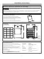 2
2
-
 3
3
-
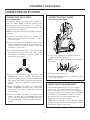 4
4
-
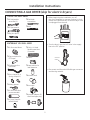 5
5
-
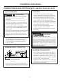 6
6
-
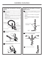 7
7
-
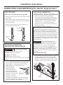 8
8
-
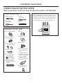 9
9
-
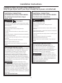 10
10
-
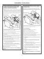 11
11
-
 12
12
-
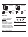 13
13
-
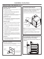 14
14
-
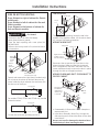 15
15
-
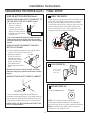 16
16
-
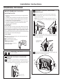 17
17
-
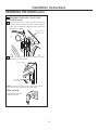 18
18
-
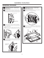 19
19
-
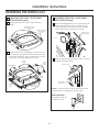 20
20
-
 21
21
-
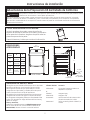 22
22
-
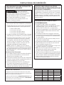 23
23
-
 24
24
-
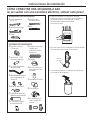 25
25
-
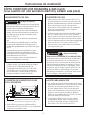 26
26
-
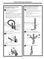 27
27
-
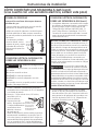 28
28
-
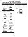 29
29
-
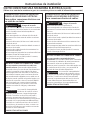 30
30
-
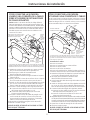 31
31
-
 32
32
-
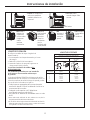 33
33
-
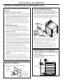 34
34
-
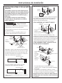 35
35
-
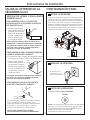 36
36
-
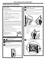 37
37
-
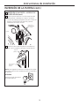 38
38
-
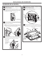 39
39
-
 40
40


GE GEWADREW4651 Guía de instalación
- Categoría
- Secadoras de ropa eléctricas
- Tipo
- Guía de instalación
En otros idiomas
- English: GE GEWADREW4651 Installation guide