
Determine if your cabinet has a
recessed area or a smooth, flat
bottom. See Fig. 1. If smooth, tape
template onto the bottom surface
(Fig. 2). If it is recessed, cut the edges
of the template to fit in the recessed
bottom of the cabinet. it is important
that the edges of the cabinets permit
level installation of the oven.
NOTE: On some cabinets a small
bracket or glue block is used between
the overhang and the underside of the
cabinet bottom. Cut the template to fit
around the bracket or glue block so that
template will lie flat against the bottom
of the cabinet.
Tape the Top Cabinet Template to
the underside of the top cabinet in the
recessed area. Fig. 3.
NOTE: Make sure the rear of the
template touches the back wall (for
smooth, flat bottom cabinets) or the
back of the recess (for recessed bottom
cabinets) after cutting the edges of the
template.
Drill 3/8” diameter holes at A. & B.
CAUTION: Wear safety goggles when
drilling holes in the cabinet bottom.
Cut out the 2” diameter hole at D
for power cord. If cabinets are metal,
use the nylon grommet (see the Parts
Included section in the Installation
Instructions) to surround the opening
to protect the cord.
(FOR VERTICAL EXHAUST ONLY)
Cut out shaded area E through the
cabinet bottom for Vertical (Outside)
Exhaust locaton.
Remove the top cabinet template.
For recessed cabinets, make 2 filler
blocks out of scrap wood the size of the
shaded areas F & G. These filler
blocks must have a thickness equal to
the depth of the cabinet recess. Drill 3/8”
diameter holes in these blocks to line
up with A & B. Place the blocks so that
the holes in each block line up with the
corresponding holes in the cabinet. The
filler blocks should be at the same level
as the bottom edge of the wall cabinet
frame. Fig. 4.
RETURN TO AND PROCEED
WITH THE INSTALLATON
INSTRUCTIONS.
FILLER
BLOCK
AREA
DRILL
DIAMETER 3/8”
3/8”
13 - 3/4”
13 - 3/4”
FILLER
BLOCK
AREA
DRILL
DIAMETER 3/8”
3/8”
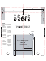
TOP CABINET TEMPLATE
E.CUT OUT FOR VERTICAL (OUTSIDE)
EXHAUST ONLY
CUT HOLE THROUGH CABINET BOTTOM FOR EXHAUST ADAPTOR
5 - 1 / 8”
6 - 7/16”
12 - 13/16”
4 - 1 / 2”
D. POWER CORD
DRILL
DIAMETER 2”
2”
WALLWALL
10 - 1 / 2”
TOP CABINET TOP CABINET TOP CABINET TOP CABINET TOP CABINET
FILLER BLOCKS
FIG. 4
FIG. 3FIG. 2
FIG. 1
Recessed
Bottom
Cabinet
7.
6.
5.
4.
3.
2.1.
Smooth
Flat Bottom
Cabinet
RIGHT SIDE
LEFT SIDE
31-7000207 Rev. 0 06-23 GEA
NOTE: IT IS VERY IMPORTANT TO READ AND FOLLOW THE DIRECTIONS
IN THE INSTALLATION INSTRUCTIONS BEFORE PROCEEDING WITH THIS
TOP CABINET TEMPLATE.
This template is used to locate the power cord clearance hole, cabinet mounting holes and
the vertical exhaust cutout.

FIG. 3
3/8”
13 - 3/4”
13 - 3/4”
3/8”
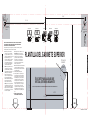
PLANTILLA DEL GABINETE SUPERIOR
5 - 1 / 8”
6 - 7/16”
12 - 13/16”
4 - 1 / 2”
2”
PAREDPARED
10 - 1 / 2”
GABINETE SUPERIOR GABINETE SUPERIOR GABINETE SUPERIOR GABINETE SUPERIOR
FIG. 3FIG. 2
31-7000207 Rev. 0 06-23 GEA
LADO IZQUIERDO
LADO DERECHO
Determine si su gabinete cuenta con
un área hueca o con una parte inferior
lisa y pareja. Consulte la Fig. 1. De ser
pareja, pegue la plantilla con cinta sobre
la superficie inferior (Fig. 2). De ser
hueca, corte los extremos de la plantilla
para que calce sobre la parte inferior
hueca del gabinete. Es importante que
los extremos de los gabinetes permitan
una instalación nivelada del horno.
NOTA: En algunos gabinetes, se utiliza
un soporte pequeño o un bloque para
pegar entre el saliente y el lado inferior
de la parte inferior del gabinete. Corte la
plantilla para que calce alrededor del
soporte o del bloque para pegar, de
modo que ésta se apoye de forma plana
contra la parte inferior del gabinete.
Encinte la Plantilla del Gabinete Superior
sobre el lado inferior del gabinete
superior en el área ahuecada. Fig. 3.
NOTA: Asegúrese de que la parte trasera
de la plantilla toque la pared trasera (para
gabinetes con parte inferior lisa y plana) o
la parte trasera del hueco (para gabinetes
con parte inferior hueca), luego de cortar
los extremos de la plantilla.
Perfore agujeros de 3/8” de diámetro en A. y B.
PRECAUCIÓN: Use gafas de seguridad al
realizar agujeros en la parte inferior del gabinete.
Corte del agujero de 2" de diámetro en D
para el cable de corriente. Si los gabinetes
son metálicos, use una arandela de nylon
(consulte la sección de Piezas Incluidas en
las Instrucciones de Instalación) para rodear
la abertura y proteger el cable.
(PARA SALIDA DE AIRE VERTICAL ÚNICAMENTE)
Corte el área sombreada E a través de la parte
inferior del gabinete para la ubicación de la Salida
de Aire Vertical (Exterior).
Retire la plantilla del gabinete superior.
Para los gabinetes huecos, haga 2 bloques de
relleno de fragmentos de madera del tamaño de
las áreas sombreadas F & G. Estos bloques de
relleno deberán poseer un grosor equivalente a
la profundidad de los huecos de los gabinetes.
Perfore agujeros de 3/8" de diámetro en estos
bloques para realizar la alineación con A & B.
Coloque los bloques de modo que los agujeros
en cada bloque se alineen con los agujeros
correspondientes en el gabinete. Los bloques de
relleno deberán estar en el mismo nivel que el
extremo inferior del marco del gabinete de pared.
Fig. 4.
REGRESE Y PROCEDA CON LAS
INSTRUCCIONES DE INSTALACIÓN.
7.
6.
5.
4.
3.
2.1.
NOTA: ES MUY IMPORTANTE LEER Y SEGUIR LOS PASOS QUE FIGURAN
EN LAS INSTRUCCIONES DE INSTALACIÓN ANTES DE PROCEDER CON
ESTA PLANTILLA PARA GABINETE SUPERIOR.
Esta plantilla se usa para ubicar el agujero de paso del cable de corriente, los agujeros de
montaje del gabinete y el recorte de la salida de aire vertical.
E. RECORTE PARA SALIDA DE AIRE
VERTICAL (EXTERIOR) ÚNICAMENTE
RECORTE EL AGUJERO A TRAVÉS DE LA PARTE INFERIOR DEL GABINETE PARA EL ADAPTADOR DEL EXTRACTOR DE AIRE
D. CABLE DE
CORRIENTE
DIÁMETRO DE
PERFORACIÓN
DE 2”
ÁREA DEL
BLOQUE DE
RELLENO
DIÁMETRO DE
PERFORACIÓN
DE 3/8”
FÁREA
DEL
BLOQUE
DE
RELLENO
DIÁMETRO DE
PERFORACIÓN
DE 3/8” GABINETE SUPERIOR
FIG. 1
Gabinete con
Fondo Hueco
Gabinete
Inferior
Parejo y
Plano
BLOQUES DE RELLENO
FIG. 4

FIG. 3
3/8 po
(9,53 mm)
13 - 3/4 po (34,95 cm)
13 - 3/4 po (34,95 cm)
5-1/8 po (13,02 cm)
6-7/16 po (16,35 cm)
12-13/16 po (32,54 cm)
4-1/2 po (11,43 cm)
2”
MURMUR
10-1/2 po (26,67 cm)
FIG. 3FIG. 2
31-7000207 Rev. 0 06-23 GEA
FIG. 1
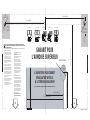
CÔTÉ GAUCHE
REMARQUE : IL EST TRÈS IMPORTANT DE LIRE ET DE RESPECTER LES DIRECTIVES
INDIQUÉES DANS LES INSTRUCTIONS D’INSTALLATION AVANT D’UTILISER CE GABARIT
POUR L’ARMOIRE SUPÉRIEURE.
1. Déterminez si votre armoire a une zone
avec renfoncement ou un fond plat et
lisse. Voir Fig. 1. S’il est plat, coller le
patron sur le fond (Fig. 2). S’il a un
renfoncement, couper les bords du
patron pour qu’il s’adapte sur le fond de
l’armoire. Il est important que les bords
des armoires permettent une installation
de niveau du four.
REMARQUE : Pour certaines armoires
un petit support ou un bloc de colle est
utilisé entre le surplomb et le dessous du
fond de l’armoire. Couper le patron pour
qu’il s’adapte autour du support ou du
bloc de colle afin que le patron puisse
être bien à plat sur le fond de l’armoire.
Scotcher le patron de l’armoire du haut
sur le dessous de l’armoire du haut dans
le renfoncement. Fig. 3.
REMARQUE : Assurez-vous que l’arrière
du patron touche le mur du fond (pour les
armoires lisses, à fond plat) ou sur
l’arrière du renfoncement (pour les
armoires avec renfoncement) après avoir
coupé les bords du patron.
2. Percer des trous de 3/8 de pouces de
diamètre à A. & B.
ATTENTION : Porter des lunettes de
protection lorsque vous percez des trous
dans le fond de l’armoire.
3. Découper le trou de 2 pouces de
diamètre au niveau D pour le cordon
d’alimentation. Si les armoires sont en
métal, utilisez des œillets en nylon (voir
les pièces incluses dans la section
Instructions d’installation) pour entourer
l’ouverture protégeant le cordon.
4. (SEULEMENT POUR ECHAPPEMENT
VERTICAL) Découper la partie ombrée E
à travers le fond de l’armoire pour la
zone de l’échappement vertical
(extérieur).
5. Retirer le patron du haut de l’armoire.
6. Pour les armoires avec renfoncement,
faire 2 calles à partir de chutes de bois
de la taille des zones ombrées F & G. Ces
cales doivent être de la même épaisseur
que celle du renfoncement de l’armoire.
Percer des trous de 3/8 pouces de
diamètre pour les aligner avec A & B.
Placer les blocs pour que les trous de
chaque trou correspondent aux trous de
l’armoire. Les blocs doivent être au
même niveau que le bord du fond du
cadre de l’armoire. Fig. 4.
7. RETOURNER AUX ET SUIVRE LES
INSTRUCTIONS D’INSTALLATION.
Ce gabarit est utilisé pour localiser le trou de dégagement du cordon d’alimentation, les trous de montage de l’armoire
et la découpe verticale de l’échappement.
PERCEZ UN TROU DANS LE FOND DE L’ARMOIRE POUR L’ADAPTATEUR D’ÉVACUATION
E. OUVERTURE POUR CONDUIT
D’ÉVACUATION VERTICAL
(À L’EXTÉRIEUR) SEULEMENT
GABARIT POUR
L’ARMOIRE SUPÉRIEUR
D. CORDON D'ALIMEN N
PERCEZ UN
TROU D'UN
DIAMÈTRE DE
2 po (5,08 cm)
CÔTÉ DROIT
PERCEZ UN
TROU DE 3/8 po
(9,53 mm) DE
DIAMÈTRE
F.
ZONE
D’ENTRETOISE
ARMOIRE SUPÉRIEURE ARMOIRE SUPÉRIEURE ARMOIRE SUPÉRIEURE ARMOIRE SUPÉRIEURE ARMOIRE SUPÉRIEURE
Armoire à
fond doté
d’un rebord
Armoire à
fond doté
d'un rebord
avec gabarit
ENTRETOISES
FIG. 4
3/8” ZONE
D'ENTRETOISE
PERCEZ UN
TROU DE 3/8 po
(9,53 mm) DE
DIAMÈTRE
3/8 po
(9,53 mm)
-
 1
1
-
 2
2
-
 3
3


en otros idiomas
- français: Monogram UVM9125STSS Guide d'installation
- English: Monogram UVM9125STSS Installation guide