
EN
DE
FR
ES
ZH
JA
Powered Near-field Reference Monitors & Subwoofer
OWNER’S MANUAL
BEDIENUNGSANLEITUNG
MODE D’EMPLOI
MANUAL DE INSTRUCCIONES

The above warning is located on the rear of the unit.
Explanation of Graphical Symbols
The lightning flash with arrowhead symbol
within an equilateral triangle is intended to alert
the user to the presence of uninsulated
“dangerous voltage” within the product’s
enclosure that may be of sufficient magnitude to
constitute a risk of electric shock to persons.
The exclamation point within an equilateral
triangle is intended to alert the user to the
presence of important operating and
maintenance (servicing) instructions in the
literature accompanying the product.
IMPORTANT SAFETY INSTRUCTIONS
1 Read these instructions.
2Keep these instructions.
3 Heed all warnings.
4 Follow all instructions.
5 Do not use this apparatus near water.
6 Clean only with dry cloth.
7 Do not block any ventilation openings. Install in
accordance with the manufacturer’s instructions.
8 Do not install near any heat sources such as radiators,
heat registers, stoves, or other apparatus (including
amplifiers) that produce heat.
9 Do not defeat the safety purpose of the polarized or
grounding-type plug. A polarized plug has two blades
with one wider than the other. A grounding type plug
has two blades and a third grounding prong. The wide
blade or the third prong are provided for your safety. If
the provided plug does not fit into your outlet, consult
an electrician for replacement of the obsolete outlet.
10 Protect the power cord from being walked on or pinched
particularly at plugs, convenience receptacles, and the
point where they exit from the apparatus.
11 Only use attachments/accessories specified by the
manufacturer.
12 Use only with the cart, stand,
tripod, bracket, or table specified
by the manufacturer, or sold with
the apparatus. When a cart is
used, use caution when moving
the cart/apparatus combination
to avoid injury from tip-over.
13 Unplug this apparatus during
lightning storms or when unused for long periods of
time.
14 Refer all servicing to qualified service personnel.
Servicing is required when the apparatus has been
damaged in any way, such as power-supply cord or plug
is damaged, liquid has been spilled or objects have
fallen into the apparatus, the apparatus has been
exposed to rain or moisture, does not operate normally,
or has been dropped.
(98-6500)
• This applies only to products distributed by Yamaha-Kemble Music (U.K.) Ltd.(3
wires)
CAUTION: TO REDUCE THE RISK OF
ELECTRIC SHOCK, DO NOT REMOVE
COVER (OR BACK). NO USER-SERVICEABLE
PARTS INSIDE. REFER SERVICING TO
QUALIFIED SERVICE PERSONNEL.
CAUTION
RISK OF ELECTRIC SHOCK
DO NOT OPEN
WARNING
TO REDUCE THE RISK OF FIRE OR ELECTRIC SHOCK, DO NOT EXPOSE THIS APPARATUS TO RAIN OR MOISTURE.
IMPORTANT
Please record the serial number of this unit in the space below.
Model:
Serial No.:
The serial number is located on the bottom or rear of the unit.
Retain this Owner's Manual in a safe place for future reference.
IMPORTANT NOTICE FOR THE UNITED KINGDOM
Connecting the Plug and Cord
WARNING: THIS APPARATUS MUST BE EARTHED
IMPORTANT. The wires in this mains lead are coloured in
accordance with the following code:
GREEN-AND-YELLOW : EARTH
BLUE : NEUTRAL
BROWN : LIVE
As the colours of the wires in the mains lead of this apparatus may
not correspond with the coloured markings identifying the
terminals in your plug proceed as follows:
The wire which is coloured GREEN-and-YELLOW must be
connected to the terminal in the plug which is marked by the letter
E or by the safety earth symbol or colored GREEN or GREEN-
and-YELLOW.
The wire which is coloured BLUE must be connected to the
terminal which is marked with the letter N or coloured BLACK.
The wire which is coloured BROWN must be connected to the
terminal which is marked with the letter L or coloured RED.

FrançaisEspañol EnglishDeutsch
44
45
52
53
66
66
67
67
Thank you for choosing a YAMAHA powered monitor speaker or powered subwoofer.
In order to take maximum advantage of the speaker’s features and ensure maximum performance and longevity,
please read this manual carefully before using powered monitor speaker or powered subwoofer.
Keep the manual in a safe place for future reference.
Vielen Dank dass Sie sich für einen aktiven Monitorlautsprecher oder Subwoofer von YAMAHA entschieden haben.
Um die Eigenschaften des Lautsprechers optimal zu nutzen und für höchste Leistung und Lebensdauer lesen Sie diese Anleitung
bitte genau durch, bevor Sie den aktiven Monitorlautsprecher oder Subwoofer verwenden.
Bitte bewahren Sie diese Bedienungsanleitung zum späteren Nachschlagen an einem sicheren Ort auf.
Nous vous remercions d’avoir choisi un haut-parleur de contrôle ou un caisson de basses amplifié YAMAHA.
Pour obtenir les performances optimales de vos haut-parleurs et garantir une longévité maximale, lisez attentivement ce mode
d’emploi avant d’utiliser le haut-parleur de contrôle ou le caisson de basses amplifié.
Conservez-le en lieu sûr pour pouvoir vous y référer ultérieurement.
Gracias por elegir los monitores o el subwoofer autoamplificados de Yamaha.
A fin de aprovechar al máximo las características de los altavoces y obtener un rendimiento y durabilidad óptimos,
lea atentamente este manual antes de utilizar el sistema.
Guarde este manual en un lugar seguro para futuras consultas.
Contents
4
Precautions
5
Setting Up for
Superior
Monitor Sound
Rear Panel
12
HS50M/
HS80M
13
HS10W
66
Specifications
66
Dimensions
67
Performance
graph
67
Block Diagram
Table des matières
24
Précautions
25
Configuration
du son de con-
trôle supérieur
Panneau arrière
32
HS50M/
HS80M
33
HS10W
66
Spécifications
66
Dimensions
67
Graphique des
performances
67
Schéma
d’ensemble
Inhalt
14
Vorsichts
-
maßnahmen
15
Aufstellung für
den besten
Klang
Rückseite
22
HS50M/
HS80M
23
HS10W
66
Technische Daten
66
Abmessungen
67
Leistungs
diagramm
67
Blockschaltbild
Contenido
34
Precauciones
35
Configuración
para obtener una
monitorización de
sonido excelente
Panel posterior
42
HS50M/
HS80M
43
HS10W
66
Especificaciones
66
Dimensiones
67
Gráfico de
rendimiento
67
Diagrama de
bloques
54
56
63
HS50M/
HS80M
64
HS10W
65
66
67
67
67

(5)-4
English
PRECAUTIONS
PLEASE READ CAREFULLY BEFORE PROCEEDING
* Please keep this manual in a safe place for future reference.
WARNING
Always follow the basic precautions listed below to avoid the possibility of serious injury or even death from electrical shock, short-
circuiting, damages, fire or other hazards. These precautions include, but are not limited to, the following:
• Only use the voltage specified as correct for the device. The required voltage is printed on
the name plate of the device.
• Use only the included power cord.
• Do not place the power cord near heat sources such as heaters or radiators, and do not
excessively bend or otherwise damage the cord, place heavy objects on it, or place it in a
position where anyone could walk on, trip over, or roll anything over it.
• Be sure to connect to an appropriate outlet with a protective grounding connection.
Improper grounding can result in electrical shock.
• Do not open the device or attempt to disassemble the internal parts or modify them in any
way. The device contains no user-serviceable parts. If it should appear to be malfunctioning,
discontinue use immediately and have it inspected by qualified Yamaha service personnel.
• Do not expose the device to rain, use it near water or in damp or wet conditions, or place
containers on it containing liquids which might spill into any openings.
• Never insert or remove an electric plug with wet hands.
• If the power cord or plug becomes frayed or damaged, or if there is a sudden loss of sound
during use of the device, or if any unusual smells or smoke should appear to be caused by
it, immediately turn off the power switch, disconnect the electric plug from the outlet, and
have the device inspected by qualified Yamaha service personnel.
• If this device should be dropped or damaged, immediately turn off the power switch,
disconnect the electric plug from the outlet, and have the device inspected by qualified
Yamaha service personnel.
CAUTION
Always follow the basic precautions listed below to avoid the possibility of physical injury to you or others, or damage to the device or other
property. These precautions include, but are not limited to, the following:
• Remove the electric plug from the outlet when the device is not to be used for extended
periods of time, or during electrical storms.
• When removing the electric plug from the device or an outlet, always hold the plug itself and
not the cord. Pulling by the cord can damage it.
• Before moving the device, remove all connected cables.
• When setting up the device, make sure that the AC outlet you are using is easily accessible.
If some trouble or malfunction occurs, immediately turn off the power switch and disconnect
the plug from the outlet.
• Do not use the device in a confined, poorly-ventilated location. Make sure that there is
adequate space between the device and surrounding walls or other devices: at least 20cm at
the sides, 20cm behind and 20cm above. Inadequate ventilation can result in overheating,
possibly causing damage to the device(s), or even fire.
• Do not expose the device to excessive dust or vibrations, or extreme cold or heat (such as in
direct sunlight, near a heater, or in a car during the day) to prevent the possibility of panel
disfiguration or damage to the internal components.
• Do not place the device in an unstable position where it might accidentally fall over.
• Before connecting the device to other devices, turn off the power for all devices. Before
turning the power on or off for all devices, set all volume levels to minimum.
• When turning on the AC power in your audio system, always turn on the device LAST, to
avoid speaker damage. When turning the power off, the device should be turned off FIRST
for the same reason.
• Do not insert your fingers or hands in any gaps or openings on the device (ports, etc.).
•Avoid inserting or dropping foreign objects (paper, plastic, metal, etc.) into any gaps or
openings on the device (ports, etc.) If this happens, turn off the power immediately and
unplug the power cord from the AC outlet. Then have the device inspected by qualified
Yamaha service personnel.
• Do not use the device for a long period of time at a high or uncomfortable volume level,
since this can cause permanent hearing loss. If you experience any hearing loss or ringing
in the ears, consult a physician.
• Do not operate the device if the sound is distorting. Prolonged use in this condition could
cause overheating and result in fire.
• Do not rest your weight on the device or place heavy objects on it, and avoid use excessive
force on the buttons, switches or connectors.
Even though this speaker system (HS50M, HS80M only) is magnetically shielded, you may need to move the speaker further away from the video monitor, if a nearby video monitor exhibits any
distortion or unnatural color shift.
Interference From Cell Phones
Using a cell phone near the speaker system can induce noise. If this occurs, move the cell phone further away from the speaker system.
Always turn the power off when the device is not in use.
The performance of components with moving contacts, such as switches, volume controls, and connectors, deteriorates over time. Consult qualified Yamaha service personnel about replacing
defective components.
• Illustrations in this manual are for explanatory purposes only, and may not match the actual appearance of the product during operation.
• Company names and product names used in this Owner’s Manual are trademarks or registered trademarks of their respective owners.
• Specifications and descriptions in this owner’s manual are for information purposes only. Yamaha Corp. reserves the right to change or modify products or specifications at any time without prior notice. Since specifications,
equipment or options may not be the same in every locale, please check with your Yamaha dealer.
Power supply/Power cord
Do not open
Water warning
If you notice any abnormality
Power supply/Power cord
Location
Connections
Handling caution
XLR-type connectors are wired as follows (IEC60268 standard): pin 1: ground, pin 2: hot (+), and pin 3: cold (-).
Yamaha cannot be held responsible for damage caused by improper use or modifications to the device.

English
HS80M/HS50M/HS10W Owner’s Manual
5
Setting Up for Superior
Monitor Sound
Setting Up for Superior
Monitor Sound
Unlike most other audio and production gear, the way speakers are set up in a
room has a dramatic effect on the final sound. This short tutorial provides a basic
guide to help you maximize the performance of your Yamaha HS-series monitor
speakers.
Listening vs. Monitoring
You’d think that the requirements for “listening” and
“monitoring” would be the same, but that is not always
the case. A great listening system can be a great
monitoring system, and vice-versa, but in most cases you’ll
miss details that are essential to producing the best
possible mix on a system that’s set up purely for musical
enjoyment. The difference is somewhat similar to the
difference between a retouched glamour portrait and the
original in which every blemish is clearly visible. The model
looks a lot better in the retouched photo, but the reality is
in the original un-enhanced version. As mixing engineer,
or producer, or sonic artist, you’ll want to hear the details
so that you can create a perfectly balanced mix that will
sound good on the widest possible range of audio systems
— and that can mean anything from high-ticket boutique
audio components in a properly-designed listening room
right down to the boom box on top of the fridge in the
kitchen. You don’t want problems hidden by poor monitor
performance to sabotage your sound on other systems.
The legendary Yamaha NS10M became a standard
monitor in the music and sound industry (and is still in use
in many studios throughout the world) for precisely that
reason: it offered flat response and excellent resolution that
allowed engineers and producers to hear subtle details that
make the difference between good and great sound. The
HS-series monitors carry on the tradition with accuracy and
detail that can help you make great mixes, while letting
you monitor for long stretches with minimum fatigue.
Getting Connected
Powered monitors offer many sonic and practical
advantages over passive types, but since they’re driven by
line-level signals you need to exercise the same care in
choosing cables and connectors as for the other line-level
connections in your studio. Always use high quality cables
and connectors, and keep cable runs as short as possible.
Unbalanced lines are fine for relatively short cables runs
unless you happen to be in a location that is plagued by
high levels of electrical and radio-frequency noise. Of
course if you’re using equipment that only has unbalanced
outputs you have no choice, and will need to set up your
system so that everything can be connected with the
shortest possible unbalanced cables. If your mixer and
monitors are located on the same desktop or tabletop, for
example, there should be no problem. But if you need to
run line-level cables longer than about three meters
(longer than about 10 feet), you might be better off using
balanced connections for maximum noise resistance.
The HS-series studio monitors provide two types of
connectors for input, so you can choose the type that best
matches your system requirements.

English
6
HS80M/HS50M/HS10W Owner’s Manual
XLR-type Connector (Balanced)
This is the type of connector most commonly used in
professional equipment and installations. 3-pin XLR-type
connectors like the ones provided on the HS-series
monitors are primarily intended for use with balanced
signals, and their solid design and construction ensures
maximum electrical and mechanical reliability.
Phone Jack (TRS, Balanced or Unbalanced)
RCA Pin Jack
The HS-series studio monitors also feature 1/4-inch
phone jack connectors that can be used for either balanced
or unbalanced connections.
For balanced connection via these jacks you’ll need to
use balanced cables fitted with TRS phone plugs — three-
contact phone plugs that are basically the same as
standard stereo phone plugs with tip, ring, and sleeve
contacts (thus the “TRS” designation — see the illustration
on the left.)
The phone jacks will also accept unbalanced signals
—simply plug in a standard mono phone plug. But what if
you want to connect equipment that only provides RCA-
type pin connector outputs? The solution is simple
enough: use either RCA-to-phone plug adaptors or RCA-
to-phone cables, and plug into the speaker’s phone-jack
inputs.
If you’re connecting your HS
speakers directly to a mixer such as
one of the Yamaha MG-series mixers,
they should usually be connected to
the mixer’s “C-R” (Control Room)
outputs so that you can control the
monitor level without affecting the
level of the signal sent to the mixer’s
main bus, which will usually be
feeding your recorder or DAW
(Digital Audio Workstation) in a
production type setup.
Pin 2: Signal + or “Hot”
Pin 3: Signal - or “Cold”
Pin 1: Ground
Pin 1: Ground
Pin 3: Signal - or “Cold”
Pin 2: Signal + or “Hot”
Ring: Signal - or “Cold”
Tip: Signal + or “Hot”
Sleeve: Ground
Tip: Signal + or “Hot”
Sleeve: Ground
input
input
LRC-R
OUT
LRST
OUT
MG Series

English
HS80M/HS50M/HS10W Owner’s Manual
7
The HS-series speakers are also an excellent choice for
direct connection to your electronic keyboard or other
electronic musical instrument.
Speaker Placement
Speaker placement is one of the most important
considerations when setting up a monitor system, but it is
all too often overlooked with the result that performance is
seriously compromised. Admittedly the obstacles to
perfect speaker positioning in the small studio are
formidable. Having the space available to place your
speaker system so that it can provide optimum
performance is a luxury, but it is definitely worth the time
spent doing a little experimentation and measuring to
make the most of limited resources. The difference can be
astounding. The basics are the same whether you’re
setting up a stereo or 5.1 surround system.
Proximity to
Walls and Corners
For the most accurate response your speakers should be
positioned away from walls and especially corners, which
can play havoc with a speaker’s frequency characteristics. A
minimum of about 1.5 meters (about 5 feet) away from
walls would be ideal, but in reality they’ll probably end up
being placed on a desktop and pushed up against a wall.
Just keep in mind that fact that the closer you get to walls
and corners the more exaggerated the speaker’s bass
response is likely to become, and some compensation —
whether you compensate mentally or use some
equalization — will probably be required. The HS50M and
HS80M speakers make this easy by providing a ROOM
CONTROL switch that modifies the speaker’s bass
characteristics to compensate for the exaggeration caused
by nearby walls. As your speakers get closer to the walls
you might find that setting the ROOM CONTROL switch
to the “-2” or “-4” setting gives you more natural response
in the bass range. As a reference, remember that you’re
trying to approach the way the speakers sound when
they’re located more than 1.5 meters (5 feet) away from
the nearest walls.
Symmetry
As we’ve just learned, the response of a speaker can
change drastically according to where it is placed in
relation to surfaces. So what happens if one of your
speakers is up against a wall and the other is out in the
open? Rest assured that the results will not be good, and
will definitely not be conducive to producing good mixes.
You’ll have totally different response from your left and
right speakers, making it next to impossible to create a
well-balanced mix, or even position tracks accurately in the
stereo sound field. So whatever you do, if you’re serious
about your sound make sure that your speakers are located
as symmetrically within your listening environment as
possible. Use a tape measure to ensure that your speakers
are the same distance from the side and rear walls. Large
objects can throw the acoustic symmetry of a room off
balance, too. It’s also important to be aware of the location
of doors and windows. It is not always possible to achieve
ideal symmetry, but it’s worth getting as close as possible.

English
8
HS80M/HS50M/HS10W Owner’s Manual
The “Sweet Spot”
For both stereo and surround mixing
your position in relation to the main front
speakers — the “sweet spot” as it’s often
called — should be one apex of an
equilateral triangle. In other words your
distance from either speaker should be the
same as the distance between the two
speakers. The speakers should also be
“toed in” to the corresponding 60° angle
so that the drivers are aimed directly at the
listening position. The height of the
speakers should be such that the tweeters
are roughly aligned with your ears (this is
because high frequencies are the most
directional).
Fine-tuning for Stereo
●The speaker LEVEL controls should be set to the same level. A setting of about 12 o’clock corresponds to a nominal
input level of about +4 dB.
●Since no subwoofer is being used in this setup, set the LOW CUT switch to “FLAT”.
●When set to “-2 dB” the EQ MID switch attenuates the midrange frequencies slightly to produce a somewhat “softer”
sound that may be better for listening or long monitoring sessions. For accurate monitoring, however, set the MID
switch to “0”.
●Set the ROOM CONTROL switch according to the distance your speakers are placed from the nearest wall (refer to
“Proximity to Walls and Corners”, above).
●For accurate monitoring set the HIGH TRIM switch to “0”. This switch can be set to “-2 dB” to attenuate the highs
slightly if you find the sound too bright.
60˚

English
HS80M/HS50M/HS10W Owner’s Manual
9
R
C
LFE
RS
LS
L
30˚30˚
100
120˚100 120˚
Adding a Subwoofer
Even if you don’t plan to set up a surround system, adding a subwoofer can be a real advantage for stereo mixing. If you
can’t hear the extreme low end there’s not much you can do to make it sound great. The extended bass response provided
by a good subwoofer can indeed help you to improve the overall quality of your mixes.
The location of your subwoofer is not as critical as the main speakers, because frequencies below around 200 Hz — the
region your subwoofer will be working in — aren’t directional. To say it another way, the ear can’t locate the source of such
low frequencies, so in theory the subwoofer can be placed anywhere in the room. In reality it’s a good idea to place the
subwoofer on the floor somewhere between the main front speakers at the same distance from the listening position as the
main speakers, but it doesn’t have to be dead center.
Fine-tuning for Stereo + Subwoofer
●Set the HS50M or HS80M LEVEL control to about 12 o’clock to set the nominal input level to approximately +4dB. If
you’re using the HS50M set the HS10W LEVEL control to about 10 o’clock, and if you’re using the HS80M set it to
about 11 o’clock. You can then fine-adjust the HS10W LEVEL control as required. Another approach would be to adjust
the HS50M/HS80M output level to achieve the desired relativebalance with the subwoofer.
●Start with the HIGH CUT control set at its center click position, which corresponds to a HPF frequency of about 100 Hz.
The HIGH CUT frequency can be adjusted later to achieve the smoothest integration with the HS50M or HS80M
speakers.
●Turn the HS10W LOW CUT switch ON. Adjust the LOW CUT control to achieve the desired degree of bass extension.
●Set the HS50M/HS80M LOW CUT switch to “FLAT”.
●When set to “-2 dB” the HS50M/HS80M EQ MID switch attenuates the midrange frequencies slightly to produce a
somewhat “softer” sound that may be better for listening or long monitoring sessions. For accurate monitoring,
however, set the MID switch to “0”.
●Set the HS50M/HS80M ROOM CONTROL switch according to the distance your speakers are placed from the nearest
wall (refer to “Proximity to Walls and Corners”, above).
●For accurate monitoring set the HS50M/HS80M HIGH TRIM switch to “0”. This switch can be set to “-2 dB” to
attenuate the highs slightly if you find the sound too bright.
Setting Up for Surround
If you’re going to be mixing for surround, obviously you’ll need a surround
monitoring system. For a 5.1 surround system, for example, you only need to
add a center speaker and two rear speakers to the stereo + subwoofer
system described in the previous section. Let’s see … two main speakers
plus one center speaker plus two rear speakers is a total of five
speakers, and “.1” refers to the subwoofer. All present and
accounted for!
According to the ITU (International Telecommunications Union)
specifications for 5.1 surround setup, the main front speakers are
positioned in the 60° equilateral triangle relationship to the listening
position described earlier, and the rear speakers should be located at
the same distance from the listening position, but at an angle of between

English
10
HS80M/HS50M/HS10W Owner’s Manual
100° and 120°, as shown in the diagram above. The center speaker should be placed precisely midway between the main
front speakers, at the same distance from the listening position as the other speakers (which means that ideally it will be a bit
behind the main left and right speakers.
As you may have deduced by now, the main left and right, center, and rear speakers are all located on the circumference
of a circle with its center at the listening position. An easy way to get all the distances right is to use a piece of string cut or
marked to the exact distance between the main left and right speakers. Attach the string to a mic stand or other convenient
object at the listening position and use it to measure the distance from the listening position to each of the speakers.
Stretched from the listening position to the speaker position the string will also provide a convenient guide for aligning the
speakers so that they point directly at the listening position.
MG-series Mixer Setup
If you’re connecting to a standard mixer that is not specifically
designed for surround production, your main L and R speakers
can be connected to any convenient stereo output pair via the
HS10W subwoofer, while the center and rear speakers will be
connected to individual output channels.
Example: MG16/6FX
Digital Mixer Setup
If you’re connecting your HS-series speakers to a mixing console
that features built-in surround handling capability — such as the
Yamaha DM2000, DM1000, or 02R96 — each speaker will be
connected directly to the console output dedicated to handling
that particular surround channel. In this type of setup you can take
full advantage of the console’s advanced surround mixing and bass
management facilities.
DVD
Player
Input Channel
Output
Connector
Speaker
L ➔ Ch1 (ST=ON, PAN ➔ L) ➔ ST OUT (L) ➔ L
R ➔ Ch2 (ST=ON, PAN ➔ R) ➔ ST OUT (R) ➔ R
LS ➔ Ch3 (GRP1-2, PAN ➔ L) ➔ GROUP OUT 1(L) ➔ LS
RS ➔ Ch4 (GRP1-2, PAN ➔ R) ➔ GROUP OUT 2(R) ➔ RS
C ➔ Ch5 (GRP3-4, PAN ➔ L) ➔ GROUP OUT 3 ➔ C
LFE ➔
Ch6 (ST=ON, PAN➔Center,
Fader➔+10 dB Boost)
➔ ST OUT ➔ LFE
DVD Player
6 Channel Line
LS
RS
LFE
R
L
C
OMNI Out
LS
RS
R
LFE
C
L

English
HS80M/HS50M/HS10W Owner’s Manual
11
Fine-tuning for Surround
●Set the HS50M or HS80M LEVEL control to about 12
o’clock to set the nominal input level to
approximately +4dB. If you’re using the HS50M
set the HS10W LEVEL control to about 10 o’clock,
and if you’re using the HS80M set it to about 11
o’clock. You can then fine-adjust the HS10W LEVEL
control as required. Another approach would be to
adjust the HS50M/HS80M output level to achieve
the desired relative balance with the subwoofer.
* If you’re using the HS50M with a digital mixer, set the
HS10W LEVEL control to about 9 o’clock. If you’re using
the HS80M with a digital mixer set the HS10W LEVEL
control to about 10 o’clock.
●Start with the HIGH CUT control set at its center
click position, which corresponds to a HPF frequency
of about 100 Hz*. The HIGH CUT frequency can be
adjusted later to achieve the smoothest integration
with the HS50M or HS80M speakers.
* Set to 80 Hz if you’re using a digital mixer.
●Turn the HS10W LOW CUT switch ON. Adjust the
LOW CUT control to achieve the desired degree of
bass extension.
●Set the HS50M/HS80M LOW CUT switch to “100
Hz”*.
* Set to 80 Hz if you’re using a digital mixer.
●When set to “-2 dB” the HS50M/HS80M EQ MID
switch attenuates the midrange frequencies slightly
to produce a somewhat “softer” sound that may be
better for listening or long monitoring sessions. For
accurate monitoring, however, set the MID switch
to “0”.
●Set the HS50M/HS80M ROOM CONTROL switch
according to the distance your speakers are placed
from the nearest wall (refer to “Proximity to Walls
and Corners”, above).
●For accurate monitoring set the HS50M/HS80M
HIGH TRIM switch to “0”. This switch can be set to
“-2 dB” to attenuate the highs slightly if you find the
sound too bright.
Maintain a Consistent
Monitoring Level
Another difference between listening and monitoring is
that when you’re listening for enjoyment you probably
listen at significantly different levels at different times: from
soft and unobtrusive for background music, right though
room-shaking for involved listening or dancing. This is
definitely not the case for serious monitoring. The response
of your ears changes so drastically according to level,
especially in the soft to medium-loud region, that is
essential to maintain a consistent monitoring level
otherwise you simply won’t get consistent mixing results.
You’ll undoubtedly need to turn up or down a bit at
certain points during the production process when
listening for specific problems or effects — in fact it is
important to listen to your mix at different levels as a final
checking process, bringing the levels down very low to
check if any elements of the mix disappear and make sure
that the vocal continues to maintain its balance in the mix
at very low levels — but in general you should stay within a
fairly small range.
Just what is the best level to monitor at? Although there
is a “standard” monitoring level specification,* the answer
for most small studios is “whatever is most comfortable for
you.” You need to monitor at a level that’s loud enough so
that you don’t miss any soft details, but not so loud that
your ears become fatigued (or your neighbors complain). If
you find yourself turning up the volume after monitoring
for a short while, your ears are probably starting to get
tired and losing sensitivity. This is obviously bad for your
music as well as your ears. So find that “comfort zone” and
prepare to make some great music.
*For you techies, the SMPTE RP 200 standard monitoring level is
83 dB SPL (RMS average) at the listening position, or if you’re
mixing for film you’ll need to know that the standard Dolby
monitoring level for surround is 85 dB SPL.

English
12
HS80M/HS50M/HS10W Owner’s Manual
Rear Panel
HS80M, HS50M
1 POWER switch
Turns power to the speaker on or off. When the power is
turned on the tuning fork mark on the front panel will light.
" LEVEL control
Adjusts the overall output level.
# INPUT 1/2 connector
These are balanced XLR-type and phone type input
connectors.
Do NOT use both the XLR and Phone type connector at the same
time. Please connect to only one of these connectors.
$ MID EQ switch
Adjusts the level of the mid-frequency range. Setting the
switch to the “0” position produces a flat frequency response.
With the “+2 dB” setting, the mid range is boosted by 2 dB.
With the “-2 dB” setting, the mid range is cut by -2 dB.
(Center frequency is 2 kHz.)
% ROOM CONTROL switch
Corrects the low frequency exaggeration caused by reflecting
off ceilings, walls and floors. Setting the switch to the “0”
position produces a flat frequency response. With the “-2 dB”
setting, the range below 500 Hz is cut by 2 dB. With the “-4
dB” setting, the range below 500 Hz is cut by -4 dB.
& HIGH TRIM switch
Adjusts the level of high-frequency range.
HS50M: Setting the switch to the “0” position produces a flat
frequency response.
With the “+2 dB” setting, the range above 3 kHz is
boosted by 2 dB. With the “-2 dB” setting, the
range above 3 kHz is cut by -2 dB.
HS80M: Setting the switch to the “0” position produces a flat
frequency response.
With the “+2 dB” setting, the range above 2 kHz is
boosted by 2 dB. With the “-2 dB” setting, the
range above 2 kHz is cut by -2 dB.
' LOW CUT switch
Cuts the low-frequency range. With the “80 Hz” setting the
range below 80 Hz is cut. With the “100 Hz” setting the range
below 100 Hz is cut.
( AC IN Connector
Connect the supplied power cable here. First connect the
power cord to the speaker, then insert the power cord plug
into the AC outlet.
ROOM CONTROL
HIGH TRIM
+2dB
+2dB
0dB
0dB
-2dB
-2dB
0dB
-2dB
-4dB
+2dB
0
-2dB
0
-2dB
-4dB
+2dB
0
-2dB
-10dB
+4dB
1
2
MID EQ
ROOM
CONTROL
HIGH
TRIM
LOW CUT
FLAT
80Hz
100Hz
MID EQ
LOW CUT
OFF
INPUT
LEVEL
POWER
ON
AC IN
2kHz
3kHz
500Hz
100Hz
80Hz
FLAT
MIN
+2dB
+2dB
0dB
0dB
-2dB
-2dB
0dB
-2dB
-4dB
2kHz
2kHz
500Hz
100Hz
FLAT
80Hz
ROOM CONTROL
HIGH TRIM
MID EQ
LOW CUT
HS50MHS80M
!
"
#
$
%
&
'
(

English
HS80M/HS50M/HS10W Owner’s Manual
13
HS10W
! POWER switch
Turns power to the speaker on or off. When the power is
turned on the tuning fork mark on the front panel will light.
" INPUT L/R connector
These are balanced XLR-type and phone type input
connectors.
Two different signals can be input at these INPUT connectors.
If two signals are input at the same time, they are mixed
before being sent to the subwoofer.
Do NOT use both the XLR and Phone type connector at the same
time. Please connect to only one of these connectors.
# EXT SUB OUT connector
This is an XLR-type balanced output connector which outputs
the mixed signal received by the INPUT L/R connectors. Use
the EXT SUB OUT connector if you wish to add a second
subwoofer.
n The LOW CUT switch/control and HIGH CUT control do not affect
the output level of the signal sent from the EXT SUB OUT
connector.
$ OUTPUT L/R jack
These XLR-type balanced output connectors output the
signals received at the INPUT L/R connectors, respectively. If
the LOW CUT switch is on, the low frequency is cut. Use the
LOW CUT control to set the cutoff frequency from 80 Hz to
120 Hz.
% LOW CUT switch
If the LOW CUT switch is on, the low frequencies of the signal
from the OUTPUT connector is cut. Use the LOW CUT control
to set the cutoff frequency from 80 Hz to 120 Hz.
& LOW CUT control
Use the LOW CUT control to set the cutoff frequency from 80
Hz to 120 Hz when the LOW CUT switch is on.
' HIGH CUT control
Use the HIGH CUT control to set the cutoff frequency of the
signal output from the HS10W from 80 Hz to 120 Hz.
( LEVEL control
Adjusts the overall output level.
) PHASE switch
Selects a phase of output sound from the HS10W.
You will usually set this switch to “NORM”. However, the
“REV.” setting may improve low-range response, depending
on the type and location of the entire speaker system. Try
both settings and select the one that produces the best low-
end sound.
* AC IN Connector
Connect the supplied power cable here. First connect the
power cord to the subwoofer, then insert the power cord plug
into the AC outlet.
L
R
L
R
LR
OFF
OFF
LR
010
80 120
100 100
80 120
INPUT EXT
SUB
OUT
OUTPUT
HIGH
CUT
LEVEL
(Hz)
(Hz)
NORM.
REV.
INPUT OUTPUT
EXT SUB OUT
SUBWOOFER
HIGH
CUT
PHASE
LOW CUT
LOW CUT
POWER
ON
AC IN
LOW
CUT
PHASE
ON
!
*
"#$&'()
%

English Deutsch Français Español
66
HS50M
165 (6-1/2") 222 (8-3/4")
268 (10-9/16")
Unit : mm(inch)
HS80M
250 (9-13/16")
332 (13-1/16")
390 (15-3/8")
Unit : mm(inch)
Specifications
Model HS50M HS80M HS10W
General Specifications
Type Biamp 2-way Powered speaker Biamp 2-way Powered speaker Powered Subwoofer
Crossover Frequency 3 kHz 2 kHz –
Overall Frequency
Response
55 Hz—20 kHz (-10 dB) 42 Hz—20 kHz (-10 dB) 30 Hz—180 Hz (-10 dB)
Dimensions (W x H x D)
165 x 268 x 222 mm
(6-1/2 x 10-9/16 x 8-3/4")
250 x 390 x 332 mm
(9-13/16 x 15-3/8 x 13-1/16")
300 x 350 x 386 mm
(11-13/16 x 13-3/4 x 15-3/16")
Weight 5.8 kg 11.3 kg 12.5 kg
Speaker Components
Speaker Components
LF : 5" cone
(Magnetic shielding Type)
LF: 8" cone
(Magnetic shielding Type)
8" cone
HF : 0.75" Dome
(Magnetic shielding Type)
HF : 1" Dome
(Magnetic shielding Type)
Enclosure
Type Bass-reflex Type Bass-reflex Type Bass-reflex Type
Material MDF MDF MDF
Amp. Unit
Output Power
Total : 70 W (dynamic power)
(LF : 45 W, 4 ohms)
(HF : 25 W, 8 ohms)
Total : 120 W(dynamic power)
(LF : 75 W, 4 ohms)
(HF : 45 W, 8 ohms)
150 W 4 ohms (dynamic power)
Input Sensitivity /
Impedance
-10 dBu/10 k ohms -10 dBu/10 k ohms -10 dBu/10 k ohms
Output Sensitivity/
Impedance
––-10 dBu/600 ohms
Input Connectors(parallel)
1 : XLR-3-31 type (balanced)
2 : PHONE (balanced)
1 : XLR-3-31 type (balanced)
2 : PHONE (balanced)
1 : XLR-3-31 type (balanced)
2 : PHONE (balanced)
Output Connectors – –
1 : XLR-3-32 type (balanced) x 1 (EXT SUB)
2 : XLR-3-32 type (balanced) x 2 (L&R)
Controls
LEVEL control (+4dB/center click)
LOW CUT switch
(FLAT/80/100 Hz, 12 dB/octave)
EQ : MID (+/- 2dB at 2kHz)
: HIGH (+/- 2dB at HF)
:ROOM CONTROL
(0/-2/-4 dB under 500Hz)
LEVEL control (+4dB/center click)
LOW CUT switch
(FLAT/80/100Hz, 12 dB/octave)
EQ : MID (+/- 2dB at 2kHz)
: HIGH (+/- 2dB at HF)
:ROOM CONTROL
(0/-2/-4 dB under 500Hz)
LEVEL control
PHASE switch : NORM./REV.
HIGH CUT control : 80–120Hz
(center click)
LOW CUT control : 80–120Hz
(center click)
LOW CUT switch : ON/OFF
Indicator Power ON : White LED Power ON : White LED Power ON : White LED
Power Consumption 45W 60W 70W
Dimensions

67
FrançaisEspañol EnglishDeutsch
10k1k100
20
0
+10
10k1k100
20
0
+10
10k1k100
20
0
+10
HS50M HS80M HS10W
RESPONSE (dB)
RESPONSE (dB)
RESPONSE (dB)
-10
-20
-30
-40
-10
-20
-30
-40
-10
-20
-30
-40
FREQUENCY (Hz)
FREQUENCY (Hz)
FREQUENCY (Hz)
HS50M / HS80M
MID EQ
INPUT 1
HIGH CUT LIMITER
HIGH TRIM
INPUT 2
LF
HF
LEVEL
LOW CUT ROOM CONTROL
LOW BOOST LOW CUT STEP FILTER P.AMP
STEP FILTER LOWCUT P.AMP
INPUT
OUTPUT
LOW CUT
OUTPUT
R ch L ch
EXTSUB OUT
LOW CUT ON/OFF
SUM
SPEAKER
PHASE
NORMAL
REVERSE
LEVEL
P.AMP
INPUT
INPUT
INPUT
LOW CUT
HIGH CUT
LIMITTER
HS10W
HS10W
386 (15-3/16")300 (11-13/16")
350 (13-3/4")
Unit : mm(inch)
Block Diagram
Performance graph

CANADA
Yamaha Canada Music Ltd.
135 Milner Avenue, Scarborough, Ontario,
M1S 3R1, Canada
Tel: 416-298-1311
U.S.A.
Yamaha Corporation of America
6600 Orangethorpe Ave., Buena Park, Calif. 90620,
U.S.A.
Tel: 714-522-9011
MEXICO
Yamaha de México S.A. de C.V.
Calz. Javier Rojo Gómez #1149,
Col. Guadalupe del Moral
C.P. 09300, México, D.F., México
Tel: 55-5804-0600
BRAZIL
Yamaha Musical do Brasil Ltda.
Av. Reboucas 2636-Pinheiros CEP: 05402-400
Sao Paulo-SP. Brasil
Tel: 011-3085-1377
ARGENTINA
Yamaha Music Latin America, S.A.
Sucursal de Argentina
Viamonte 1145 Piso2-B 1053,
Buenos Aires, Argentina
Tel: 1-4371-7021
PANAMA AND OTHER LATIN
AMERICAN COUNTRIES/
CARIBBEAN COUNTRIES
Yamaha Music Latin America, S.A.
Torre Banco General, Piso 7, Urbanización Marbella,
Calle 47 y Aquilino de la Guardia,
Ciudad de Panamá, Panamá
Tel: +507-269-5311
THE UNITED KINGDOM
Yamaha-Kemble Music (U.K.) Ltd.
Sherbourne Drive, Tilbrook, Milton Keynes,
MK7 8BL, England
Tel: 01908-366700
GERMANY
Yamaha Music Central Europe GmbH
Siemensstraße 22-34, 25462 Rellingen, Germany
Tel: 04101-3030
SWITZERLAND/LIECHTENSTEIN
Yamaha Music Central Europe GmbH,
Branch Switzerland
Seefeldstrasse 94, 8008 Zürich, Switzerland
Tel: 01-383 3990
AUSTRIA
Yamaha Music Central Europe GmbH,
Branch Austria
Schleiergasse 20, A-1100 Wien, Austria
Tel: 01-60203900
CZECH REPUBLIC/SLOVAKIA/
HUNGARY/SLOVENIA
Yamaha Music Central Europe GmbH,
Branch Austria, CEE Department
Schleiergasse 20, A-1100 Wien, Austria
Tel: 01-602039025
POLAND
Yamaha Music Central Europe GmbH
Sp.z. o.o. Oddzial w Polsce
ul. 17 Stycznia 56, PL-02-146 Warszawa, Poland
Tel: 022-868-07-57
THE NETHERLANDS/
BELGIUM/LUXEMBOURG
Yamaha Music Central Europe GmbH,
Branch Benelux
Clarissenhof 5-b, 4133 AB Vianen, The Netherlands
Tel: 0347-358 040
FRANCE
Yamaha Musique France
BP 70-77312 Marne-la-Vallée Cedex 2, France
Tel: 01-64-61-4000
ITALY
Yamaha Musica Italia S.P.A.
Combo Division
Viale Italia 88, 20020 Lainate (Milano), Italy
Tel: 02-935-771
SPAIN/PORTUGAL
Yamaha-Hazen Música, S.A.
Ctra. de la Coruna km. 17, 200, 28230
Las Rozas (Madrid), Spain
Tel: 91-639-8888
SWEDEN
Yamaha Scandinavia AB
J. A. Wettergrens Gata 1
Box 30053
S-400 43 Göteborg, Sweden
Tel: 031 89 34 00
DENMARK
YS Copenhagen Liaison Office
Generatorvej 6A
DK-2730 Herlev, Denmark
Tel: 44 92 49 00
NORWAY
Norsk filial av Yamaha Scandinavia AB
Grini Næringspark 1
N-1345 Østerås, Norway
Tel: 67 16 77 70
OTHER EUROPEAN COUNTRIES
Yamaha Music Central Europe GmbH
Siemensstraße 22-34, 25462 Rellingen, Germany
Tel: +49-4101-3030
Yamaha Corporation,
Asia-Pacific Music Marketing Group
Nakazawa-cho 10-1, Hamamatsu, Japan 430-8650
Tel: +81-53-460-2313
TURKEY/CYPRUS
Yamaha Music Central Europe GmbH
Siemensstraße 22-34, 25462 Rellingen, Germany
Tel: 04101-3030
OTHER COUNTRIES
Yamaha Music Gulf FZE
LB21-128 Jebel Ali Freezone
P.O.Box 17328, Dubai, U.A.E.
Tel: +971-4-881-5868
THE PEOPLE’S REPUBLIC OF CHINA
Yamaha Music & Electronics (China) Co.,Ltd.
25/F., United Plaza, 1468 Nanjing Road (West),
Jingan, Shanghai, China
Tel: 021-6247-2211
INDONESIA
PT. Yamaha Music Indonesia (Distributor)
PT. Nusantik
Gedung Yamaha Music Center, Jalan Jend. Gatot
Subroto Kav. 4, Jakarta 12930, Indonesia
Tel: 21-520-2577
KOREA
Yamaha Music Korea Ltd.
Tong-Yang Securities Bldg. 16F 23-8 Yoido-dong,
Youngdungpo-ku, Seoul, Korea
Tel: 02-3770-0660
MALAYSIA
Yamaha Music Malaysia, Sdn., Bhd.
Lot 8, Jalan Perbandaran, 47301 Kelana Jaya,
Petaling Jaya, Selangor, Malaysia
Tel: 3-78030900
SINGAPORE
Yamaha Music Asia Pte., Ltd.
#03-11 A-Z Building
140 Paya Lebor Road, Singapore 409015
Tel: 747-4374
TAIWAN
Yamaha KHS Music Co., Ltd.
3F, #6, Sec.2, Nan Jing E. Rd. Taipei.
Taiwan 104, R.O.C.
Tel: 02-2511-8688
THAILAND
Siam Music Yamaha Co., Ltd.
891/1 Siam Motors Building, 15-16 floor
Rama 1 road, Wangmai, Pathumwan
Bangkok 10330, Thailand
Tel: 02-215-2626
OTHER ASIAN COUNTRIES
Yamaha Corporation,
Asia-Pacific Music Marketing Group
Nakazawa-cho 10-1, Hamamatsu, Japan 430-8650
Tel: +81-53-460-2317
AUSTRALIA
Yamaha Music Australia Pty. Ltd.
Level 1, 99 Queensbridge Street, Southbank,
Victoria 3006, Australia
Tel: 3-9693-5111
COUNTRIES AND TRUST
TERRITORIES IN PACIFIC OCEAN
Yamaha Corporation,
Asia-Pacific Music Marketing Group
Nakazawa-cho 10-1, Hamamatsu, Japan 430-8650
Tel: +81-53-460-2313
NORTH AMERICA
CENTRAL & SOUTH AMERICA
EUROPE
AFRICA
MIDDLE EAST
ASIA
OCEANIA
For details of products, please contact your nearest Yamaha representative or the authorized distributor listed below.
HEAD OFFICEYamaha Corporation, Pro Audio & Digital Musical
Instrument Division
Nakazawa-cho 10-1, Hamamatsu, Japan 430-8650
Tel: +81-53-460-2441
PA13
Yamaha Pro Audio global web site
http://www.yamahaproaudio.com/
Yamaha Manual Library
http://www.yamaha.co.jp/manual/
U.R.G., Pro Audio & Digital Musical Instrument Division, Yamaha Corporation
© 2005 Yamaha Corporation
508MW-01A0
Printed in China
Transcripción de documentos
Powered Near-field Reference Monitors & Subwoofer OWNER’S MANUAL BEDIENUNGSANLEITUNG MODE D’EMPLOI MANUAL DE INSTRUCCIONES 取扱説明書 EN DE FR ES ZH JA Explanation of Graphical Symbols The lightning flash with arrowhead symbol within an equilateral triangle is intended to alert the user to the presence of uninsulated “dangerous voltage” within the product’s enclosure that may be of sufficient magnitude to constitute a risk of electric shock to persons. CAUTION RISK OF ELECTRIC SHOCK DO NOT OPEN The exclamation point within an equilateral triangle is intended to alert the user to the presence of important operating and maintenance (servicing) instructions in the literature accompanying the product. CAUTION: TO REDUCE THE RISK OF ELECTRIC SHOCK, DO NOT REMOVE COVER (OR BACK). NO USER-SERVICEABLE PARTS INSIDE. REFER SERVICING TO QUALIFIED SERVICE PERSONNEL. The above warning is located on the rear of the unit. IMPORTANT SAFETY INSTRUCTIONS 1 2 3 4 5 6 7 8 9 10 Read these instructions. Keep these instructions. Heed all warnings. Follow all instructions. Do not use this apparatus near water. Clean only with dry cloth. Do not block any ventilation openings. Install in accordance with the manufacturer’s instructions. Do not install near any heat sources such as radiators, heat registers, stoves, or other apparatus (including amplifiers) that produce heat. Do not defeat the safety purpose of the polarized or grounding-type plug. A polarized plug has two blades with one wider than the other. A grounding type plug has two blades and a third grounding prong. The wide blade or the third prong are provided for your safety. If the provided plug does not fit into your outlet, consult an electrician for replacement of the obsolete outlet. Protect the power cord from being walked on or pinched particularly at plugs, convenience receptacles, and the point where they exit from the apparatus. 11 12 13 14 Only use attachments/accessories specified by the manufacturer. Use only with the cart, stand, tripod, bracket, or table specified by the manufacturer, or sold with the apparatus. When a cart is used, use caution when moving the cart/apparatus combination to avoid injury from tip-over. Unplug this apparatus during lightning storms or when unused for long periods of time. Refer all servicing to qualified service personnel. Servicing is required when the apparatus has been damaged in any way, such as power-supply cord or plug is damaged, liquid has been spilled or objects have fallen into the apparatus, the apparatus has been exposed to rain or moisture, does not operate normally, or has been dropped. WARNING TO REDUCE THE RISK OF FIRE OR ELECTRIC SHOCK, DO NOT EXPOSE THIS APPARATUS TO RAIN OR MOISTURE. (98-6500) IMPORTANT Please record the serial number of this unit in the space below. Model: Serial No.: The serial number is located on the bottom or rear of the unit. Retain this Owner's Manual in a safe place for future reference. IMPORTANT NOTICE FOR THE UNITED KINGDOM Connecting the Plug and Cord WARNING: THIS APPARATUS MUST BE EARTHED IMPORTANT. The wires in this mains lead are coloured in accordance with the following code: GREEN-AND-YELLOW : EARTH BLUE : NEUTRAL BROWN : LIVE As the colours of the wires in the mains lead of this apparatus may not correspond with the coloured markings identifying the terminals in your plug proceed as follows: The wire which is coloured GREEN-and-YELLOW must be connected to the terminal in the plug which is marked by the letter E or by the safety earth symbol or colored GREEN or GREENand-YELLOW. The wire which is coloured BLUE must be connected to the terminal which is marked with the letter N or coloured BLACK. The wire which is coloured BROWN must be connected to the terminal which is marked with the letter L or coloured RED. • This applies only to products distributed by Yamaha-Kemble Music (U.K.) Ltd.(3 wires) Nous vous remercions d’avoir choisi un haut-parleur de contrôle ou un caisson de basses amplifié YAMAHA. Pour obtenir les performances optimales de vos haut-parleurs et garantir une longévité maximale, lisez attentivement ce mode d’emploi avant d’utiliser le haut-parleur de contrôle ou le caisson de basses amplifié. Conservez-le en lieu sûr pour pouvoir vous y référer ultérieurement. English Español Gracias por elegir los monitores o el subwoofer autoamplificados de Yamaha. A fin de aprovechar al máximo las características de los altavoces y obtener un rendimiento y durabilidad óptimos, lea atentamente este manual antes de utilizar el sistema. Guarde este manual en un lugar seguro para futuras consultas. Deutsch Vielen Dank dass Sie sich für einen aktiven Monitorlautsprecher oder Subwoofer von YAMAHA entschieden haben. Um die Eigenschaften des Lautsprechers optimal zu nutzen und für höchste Leistung und Lebensdauer lesen Sie diese Anleitung bitte genau durch, bevor Sie den aktiven Monitorlautsprecher oder Subwoofer verwenden. Bitte bewahren Sie diese Bedienungsanleitung zum späteren Nachschlagen an einem sicheren Or t auf. Français Thank you for choosing a YAMAHA powered monitor speaker or powered subwoofer. In order to take maximum advantage of the speaker’s features and ensure maximum performance and longevity, please read this manual carefully before using powered monitor speaker or powered subwoofer. Keep the manual in a safe place for future reference. このたびは、ヤマハ製品をお買い求めいただきまして、まことにありがとうございます。 製品の優れた性能を十分に生かして、末永くご愛用いただくために、この取扱説明書をご使用の前に必ずお読みください。 お読みになったあとは保証書とともに保管してください。 Contents 4 Precautions 5 Setting Up for Superior Monitor Sound Rear Panel 12 HS50M/ Inhalt 66 Specifications 66 Dimensions 67 Performance graph 67 Block Diagram 14 Vorsichtsmaßnahmen 15 Aufstellung für den besten Klang Rückseite 22 HS50M/ HS80M Table des matières 66 Technische Daten 66 Abmessungen 67 Leistungs diagramm 67 Blockschaltbild HS80M 23 HS10W 13 HS10W 24 Précautions 25 Configuration du son de contrôle supérieur Panneau arrière 32 HS50M/ HS80M 33 HS10W 66 Spécifications 66 Dimensions 67 Graphique des performances 67 Schéma d’ensemble Contenido 34 Precauciones 35 Configuración para obtener una monitorización de sonido excelente Panel posterior 42 HS50M/ HS80M 43 HS10W 66 Especificaciones 66 Dimensiones 67 Gráfico de rendimiento 67 Diagrama de bloques 目次 44 66 45 66 67 52 53 67 54 安全上のご注意 56 優れたモニター 環境の構築 リアパネル 63 HS50M/ HS80M 64 HS10W 65 サービスについて 66 仕様 67 寸法図 67 特性図 67 ブロック図 PRECAUTIONS English PLEASE READ CAREFULLY BEFORE PROCEEDING * Please keep this manual in a safe place for future reference. WARNING Always follow the basic precautions listed below to avoid the possibility of serious injury or even death from electrical shock, shortcircuiting, damages, fire or other hazards. These precautions include, but are not limited to, the following: Power supply/Power cord Water warning • Do not expose the device to rain, use it near water or in damp or wet conditions, or place containers on it containing liquids which might spill into any openings. • Never insert or remove an electric plug with wet hands. • Only use the voltage specified as correct for the device. The required voltage is printed on the name plate of the device. • Use only the included power cord. • Do not place the power cord near heat sources such as heaters or radiators, and do not excessively bend or otherwise damage the cord, place heavy objects on it, or place it in a position where anyone could walk on, trip over, or roll anything over it. • Be sure to connect to an appropriate outlet with a protective grounding connection. Improper grounding can result in electrical shock. If you notice any abnormality • If the power cord or plug becomes frayed or damaged, or if there is a sudden loss of sound during use of the device, or if any unusual smells or smoke should appear to be caused by it, immediately turn off the power switch, disconnect the electric plug from the outlet, and have the device inspected by qualified Yamaha service personnel. • If this device should be dropped or damaged, immediately turn off the power switch, disconnect the electric plug from the outlet, and have the device inspected by qualified Yamaha service personnel. Do not open • Do not open the device or attempt to disassemble the internal parts or modify them in any way. The device contains no user-serviceable parts. If it should appear to be malfunctioning, discontinue use immediately and have it inspected by qualified Yamaha service personnel. CAUTION Always follow the basic precautions listed below to avoid the possibility of physical injury to you or others, or damage to the device or other property. These precautions include, but are not limited to, the following: Power supply/Power cord Connections • Before connecting the device to other devices, turn off the power for all devices. Before turning the power on or off for all devices, set all volume levels to minimum. • Remove the electric plug from the outlet when the device is not to be used for extended periods of time, or during electrical storms. • When removing the electric plug from the device or an outlet, always hold the plug itself and not the cord. Pulling by the cord can damage it. Handling caution • When turning on the AC power in your audio system, always turn on the device LAST, to avoid speaker damage. When turning the power off, the device should be turned off FIRST for the same reason. • Do not insert your fingers or hands in any gaps or openings on the device (ports, etc.). • Avoid inserting or dropping foreign objects (paper, plastic, metal, etc.) into any gaps or openings on the device (ports, etc.) If this happens, turn off the power immediately and unplug the power cord from the AC outlet. Then have the device inspected by qualified Yamaha service personnel. • Do not use the device for a long period of time at a high or uncomfortable volume level, since this can cause permanent hearing loss. If you experience any hearing loss or ringing in the ears, consult a physician. • Do not operate the device if the sound is distorting. Prolonged use in this condition could cause overheating and result in fire. • Do not rest your weight on the device or place heavy objects on it, and avoid use excessive force on the buttons, switches or connectors. Location • Before moving the device, remove all connected cables. • When setting up the device, make sure that the AC outlet you are using is easily accessible. If some trouble or malfunction occurs, immediately turn off the power switch and disconnect the plug from the outlet. • Do not use the device in a confined, poorly-ventilated location. Make sure that there is adequate space between the device and surrounding walls or other devices: at least 20cm at the sides, 20cm behind and 20cm above. Inadequate ventilation can result in overheating, possibly causing damage to the device(s), or even fire. • Do not expose the device to excessive dust or vibrations, or extreme cold or heat (such as in direct sunlight, near a heater, or in a car during the day) to prevent the possibility of panel disfiguration or damage to the internal components. • Do not place the device in an unstable position where it might accidentally fall over. XLR-type connectors are wired as follows (IEC60268 standard): pin 1: ground, pin 2: hot (+), and pin 3: cold (-). Even though this speaker system (HS50M, HS80M only) is magnetically shielded, you may need to move the speaker further away from the video monitor, if a nearby video monitor exhibits any distortion or unnatural color shift. Interference From Cell Phones Using a cell phone near the speaker system can induce noise. If this occurs, move the cell phone further away from the speaker system. Yamaha cannot be held responsible for damage caused by improper use or modifications to the device. Always turn the power off when the device is not in use. The performance of components with moving contacts, such as switches, volume controls, and connectors, deteriorates over time. Consult qualified Yamaha service personnel about replacing defective components. • Illustrations in this manual are for explanatory purposes only, and may not match the actual appearance of the product during operation. • Company names and product names used in this Owner’s Manual are trademarks or registered trademarks of their respective owners. • Specifications and descriptions in this owner’s manual are for information purposes only. Yamaha Corp. reserves the right to change or modify products or specifications at any time without prior notice. Since specifications, equipment or options may not be the same in every locale, please check with your Yamaha dealer. (5)-4 English Setting Up for Superior Monitor Sound Unlike most other audio and production gear, the way speakers are set up in a room has a dramatic effect on the final sound. This short tutorial provides a basic guide to help you maximize the performance of your Yamaha HS-series monitor speakers. Listening vs. Monitoring You’d think that the requirements for “listening” and Getting Connected Powered monitors offer many sonic and practical “monitoring” would be the same, but that is not always advantages over passive types, but since they’re driven by the case. A great listening system can be a great line-level signals you need to exercise the same care in monitoring system, and vice-versa, but in most cases you’ll choosing cables and connectors as for the other line-level miss details that are essential to producing the best connections in your studio. Always use high quality cables possible mix on a system that’s set up purely for musical and connectors, and keep cable runs as short as possible. enjoyment. The difference is somewhat similar to the Unbalanced lines are fine for relatively short cables runs difference between a retouched glamour portrait and the unless you happen to be in a location that is plagued by original in which every blemish is clearly visible. The model high levels of electrical and radio-frequency noise. Of looks a lot better in the retouched photo, but the reality is course if you’re using equipment that only has unbalanced in the original un-enhanced version. As mixing engineer, outputs you have no choice, and will need to set up your or producer, or sonic artist, you’ll want to hear the details system so that everything can be connected with the so that you can create a perfectly balanced mix that will shortest possible unbalanced cables. If your mixer and sound good on the widest possible range of audio systems monitors are located on the same desktop or tabletop, for — and that can mean anything from high-ticket boutique example, there should be no problem. But if you need to audio components in a properly-designed listening room run line-level cables longer than about three meters right down to the boom box on top of the fridge in the (longer than about 10 feet), you might be better off using kitchen. You don’t want problems hidden by poor monitor balanced connections for maximum noise resistance. performance to sabotage your sound on other systems. The legendary Yamaha NS10M became a standard monitor in the music and sound industry (and is still in use The HS-series studio monitors provide two types of connectors for input, so you can choose the type that best matches your system requirements. in many studios throughout the world) for precisely that reason: it offered flat response and excellent resolution that allowed engineers and producers to hear subtle details that make the difference between good and great sound. The HS-series monitors carry on the tradition with accuracy and detail that can help you make great mixes, while letting you monitor for long stretches with minimum fatigue. HS80M/HS50M/HS10W Owner’s Manual 5 XLR-type Connector (Balanced) English This is the type of connector most commonly used in professional equipment and installations. 3-pin XLR-type connectors like the ones provided on the HS-series Pin 2: Signal + or “Hot” Pin 3: Signal - or “Cold” Pin 1: Ground monitors are primarily intended for use with balanced signals, and their solid design and construction ensures Pin 1: Ground Pin 3: Signal - or “Cold” Pin 2: Signal + or “Hot” maximum electrical and mechanical reliability. Phone Jack (TRS, Balanced or Unbalanced) The HS-series studio monitors also feature 1/4-inch phone jack connectors that can be used for either balanced Ring: Signal - or “Cold” Tip: Signal + or “Hot” Sleeve: Ground or unbalanced connections. For balanced connection via these jacks you’ll need to use balanced cables fitted with TRS phone plugs — three- Tip: Signal + or “Hot” Sleeve: Ground contact phone plugs that are basically the same as standard stereo phone plugs with tip, ring, and sleeve contacts (thus the “TRS” designation — see the illustration on the left.) The phone jacks will also accept unbalanced signals RCA Pin Jack —simply plug in a standard mono phone plug. But what if you want to connect equipment that only provides RCAtype pin connector outputs? The solution is simple enough: use either RCA-to-phone plug adaptors or RCAto-phone cables, and plug into the speaker’s phone-jack inputs. If you’re connecting your HS speakers directly to a mixer such as input one of the Yamaha MG-series mixers, input they should usually be connected to the mixer’s “C-R” (Control Room) outputs so that you can control the monitor level without affecting the C-R OUT L R L R ST OUT level of the signal sent to the mixer’s main bus, which will usually be feeding your recorder or DAW (Digital Audio Workstation) in a production type setup. MG Series 6 HS80M/HS50M/HS10W Owner’s Manual HS80M speakers make this easy by providing a ROOM CONTROL switch that modifies the speaker’s bass electronic musical instrument. characteristics to compensate for the exaggeration caused English The HS-series speakers are also an excellent choice for direct connection to your electronic keyboard or other by nearby walls. As your speakers get closer to the walls you might find that setting the ROOM CONTROL switch to the “-2” or “-4” setting gives you more natural response in the bass range. As a reference, remember that you’re trying to approach the way the speakers sound when they’re located more than 1.5 meters (5 feet) away from the nearest walls. Speaker Placement Speaker placement is one of the most important considerations when setting up a monitor system, but it is all too often overlooked with the result that performance is seriously compromised. Admittedly the obstacles to perfect speaker positioning in the small studio are formidable. Having the space available to place your speaker system so that it can provide optimum performance is a luxury, but it is definitely worth the time Symmetry spent doing a little experimentation and measuring to make the most of limited resources. The difference can be astounding. The basics are the same whether you’re setting up a stereo or 5.1 surround system. As we’ve just learned, the response of a speaker can change drastically according to where it is placed in relation to surfaces. So what happens if one of your speakers is up against a wall and the other is out in the open? Rest assured that the results will not be good, and Proximity to Walls and Corners will definitely not be conducive to producing good mixes. You’ll have totally different response from your left and right speakers, making it next to impossible to create a well-balanced mix, or even position tracks accurately in the For the most accurate response your speakers should be stereo sound field. So whatever you do, if you’re serious positioned away from walls and especially corners, which about your sound make sure that your speakers are located can play havoc with a speaker’s frequency characteristics. A as symmetrically within your listening environment as minimum of about 1.5 meters (about 5 feet) away from possible. Use a tape measure to ensure that your speakers walls would be ideal, but in reality they’ll probably end up are the same distance from the side and rear walls. Large being placed on a desktop and pushed up against a wall. objects can throw the acoustic symmetry of a room off Just keep in mind that fact that the closer you get to walls balance, too. It’s also important to be aware of the location and corners the more exaggerated the speaker’s bass of doors and windows. It is not always possible to achieve response is likely to become, and some compensation — ideal symmetry, but it’s worth getting as close as possible. whether you compensate mentally or use some equalization — will probably be required. The HS50M and HS80M/HS50M/HS10W Owner’s Manual 7 The “Sweet Spot” English For both stereo and surround mixing your position in relation to the main front speakers — the “sweet spot” as it’s often called — should be one apex of an equilateral triangle. In other words your distance from either speaker should be the same as the distance between the two speakers. The speakers should also be “toed in” to the corresponding 60° angle so that the drivers are aimed directly at the listening position. The height of the speakers should be such that the tweeters are roughly aligned with your ears (this is 60˚ because high frequencies are the most directional). Fine-tuning for Stereo ● The speaker LEVEL controls should be set to the same level. A setting of about 12 o’clock corresponds to a nominal input level of about +4 dB. ● Since no subwoofer is being used in this setup, set the LOW CUT switch to “FLAT”. ● When set to “-2 dB” the EQ MID switch attenuates the midrange frequencies slightly to produce a somewhat “softer” sound that may be better for listening or long monitoring sessions. For accurate monitoring, however, set the MID switch to “0”. ● Set the ROOM CONTROL switch according to the distance your speakers are placed from the nearest wall (refer to “Proximity to Walls and Corners”, above). ● For accurate monitoring set the HIGH TRIM switch to “0”. This switch can be set to “-2 dB” to attenuate the highs slightly if you find the sound too bright. 8 HS80M/HS50M/HS10W Owner’s Manual English Adding a Subwoofer Even if you don’t plan to set up a surround system, adding a subwoofer can be a real advantage for stereo mixing. If you can’t hear the extreme low end there’s not much you can do to make it sound great. The extended bass response provided by a good subwoofer can indeed help you to improve the overall quality of your mixes. The location of your subwoofer is not as critical as the main speakers, because frequencies below around 200 Hz — the region your subwoofer will be working in — aren’t directional. To say it another way, the ear can’t locate the source of such low frequencies, so in theory the subwoofer can be placed anywhere in the room. In reality it’s a good idea to place the subwoofer on the floor somewhere between the main front speakers at the same distance from the listening position as the main speakers, but it doesn’t have to be dead center. Fine-tuning for Stereo + Subwoofer ● Set the HS50M or HS80M LEVEL control to about 12 o’clock to set the nominal input level to approximately +4dB. If you’re using the HS50M set the HS10W LEVEL control to about 10 o’clock, and if you’re using the HS80M set it to about 11 o’clock. You can then fine-adjust the HS10W LEVEL control as required. Another approach would be to adjust the HS50M/HS80M output level to achieve the desired relativebalance with the subwoofer. ● Start with the HIGH CUT control set at its center click position, which corresponds to a HPF frequency of about 100 Hz. The HIGH CUT frequency can be adjusted later to achieve the smoothest integration with the HS50M or HS80M speakers. ● Turn the HS10W LOW CUT switch ON. Adjust the LOW CUT control to achieve the desired degree of bass extension. ● Set the HS50M/HS80M LOW CUT switch to “FLAT”. ● When set to “-2 dB” the HS50M/HS80M EQ MID switch attenuates the midrange frequencies slightly to produce a somewhat “softer” sound that may be better for listening or long monitoring sessions. For accurate monitoring, however, set the MID switch to “0”. ● Set the HS50M/HS80M ROOM CONTROL switch according to the distance your speakers are placed from the nearest wall (refer to “Proximity to Walls and Corners”, above). ● For accurate monitoring set the HS50M/HS80M HIGH TRIM switch to “0”. This switch can be set to “-2 dB” to attenuate the highs slightly if you find the sound too bright. Setting Up for Surround C If you’re going to be mixing for surround, obviously you’ll need a surround monitoring system. For a 5.1 surround system, for example, you only need to R L add a center speaker and two rear speakers to the stereo + subwoofer system described in the previous section. Let’s see … two main speakers 30˚ plus one center speaker plus two rear speakers is a total of five 30˚ LFE speakers, and “.1” refers to the subwoofer. All present and accounted for! 100 120˚ 100 120˚ According to the ITU (International Telecommunications Union) specifications for 5.1 surround setup, the main front speakers are positioned in the 60° equilateral triangle relationship to the listening position described earlier, and the rear speakers should be located at LS RS the same distance from the listening position, but at an angle of between HS80M/HS50M/HS10W Owner’s Manual 9 100° and 120°, as shown in the diagram above. The center speaker should be placed precisely midway between the main front speakers, at the same distance from the listening position as the other speakers (which means that ideally it will be a bit English behind the main left and right speakers. As you may have deduced by now, the main left and right, center, and rear speakers are all located on the circumference of a circle with its center at the listening position. An easy way to get all the distances right is to use a piece of string cut or marked to the exact distance between the main left and right speakers. Attach the string to a mic stand or other convenient object at the listening position and use it to measure the distance from the listening position to each of the speakers. Stretched from the listening position to the speaker position the string will also provide a convenient guide for aligning the speakers so that they point directly at the listening position. MG-series Mixer Setup C L If you’re connecting to a standard mixer that is not specifically R LFE DVD Player designed for surround production, your main L and R speakers can be connected to any convenient stereo output pair via the HS10W subwoofer, while the center and rear speakers will be 6 Channel Line connected to individual output channels. Example: MG16/6FX DVD Player LS Output Connector Input Channel Speaker L ➔ Ch1 (ST=ON, PAN ➔ L) ➔ ST OUT (L) ➔ L R ➔ Ch2 (ST=ON, PAN ➔ R) ➔ ST OUT (R) ➔ R LS ➔ Ch3 (GRP1-2, PAN ➔ L) ➔ GROUP OUT 1(L) ➔ LS RS ➔ Ch4 (GRP1-2, PAN ➔ R) ➔ GROUP OUT 2(R) ➔ RS C ➔ Ch5 (GRP3-4, PAN ➔ L) ➔ GROUP OUT 3 ➔ C Ch6 (ST=ON, PAN➔Center, ➔ Fader➔+10 dB Boost) ➔ ST OUT ➔ LFE RS LFE Digital Mixer Setup C If you’re connecting your HS-series speakers to a mixing console L R that features built-in surround handling capability — such as the LFE Yamaha DM2000, DM1000, or 02R96 — each speaker will be OMNI Out connected directly to the console output dedicated to handling that particular surround channel. In this type of setup you can take full advantage of the console’s advanced surround mixing and bass management facilities. LS 10 HS80M/HS50M/HS10W Owner’s Manual RS ● Set the HS50M or HS80M LEVEL control to about 12 o’clock to set the nominal input level to approximately +4dB. If you’re using the HS50M set the HS10W LEVEL control to about 10 o’clock, and if you’re using the HS80M set it to about 11 o’clock. You can then fine-adjust the HS10W LEVEL control as required. Another approach would be to adjust the HS50M/HS80M output level to achieve the desired relative balance with the subwoofer. * If you’re using the HS50M with a digital mixer, set the HS10W LEVEL control to about 9 o’clock. If you’re using the HS80M with a digital mixer set the HS10W LEVEL control to about 10 o’clock. ● Start with the HIGH CUT control set at its center click position, which corresponds to a HPF frequency of about 100 Hz*. The HIGH CUT frequency can be adjusted later to achieve the smoothest integration with the HS50M or HS80M speakers. * Set to 80 Hz if you’re using a digital mixer. Maintain a Consistent Monitoring Level Another difference between listening and monitoring is that when you’re listening for enjoyment you probably listen at significantly different levels at different times: from soft and unobtrusive for background music, right though room-shaking for involved listening or dancing. This is definitely not the case for serious monitoring. The response of your ears changes so drastically according to level, especially in the soft to medium-loud region, that is essential to maintain a consistent monitoring level otherwise you simply won’t get consistent mixing results. You’ll undoubtedly need to turn up or down a bit at certain points during the production process when listening for specific problems or effects — in fact it is important to listen to your mix at different levels as a final checking process, bringing the levels down very low to ● Turn the HS10W LOW CUT switch ON. Adjust the LOW CUT control to achieve the desired degree of bass extension. check if any elements of the mix disappear and make sure ● Set the HS50M/HS80M LOW CUT switch to “100 Hz”*. fairly small range. * Set to 80 Hz if you’re using a digital mixer. ● When set to “-2 dB” the HS50M/HS80M EQ MID switch attenuates the midrange frequencies slightly to produce a somewhat “softer” sound that may be better for listening or long monitoring sessions. For accurate monitoring, however, set the MID switch to “0”. English Fine-tuning for Surround that the vocal continues to maintain its balance in the mix at very low levels — but in general you should stay within a Just what is the best level to monitor at? Although there is a “standard” monitoring level specification,* the answer for most small studios is “whatever is most comfortable for you.” You need to monitor at a level that’s loud enough so that you don’t miss any soft details, but not so loud that your ears become fatigued (or your neighbors complain). If you find yourself turning up the volume after monitoring for a short while, your ears are probably starting to get ● Set the HS50M/HS80M ROOM CONTROL switch according to the distance your speakers are placed from the nearest wall (refer to “Proximity to Walls and Corners”, above). ● For accurate monitoring set the HS50M/HS80M HIGH TRIM switch to “0”. This switch can be set to “-2 dB” to attenuate the highs slightly if you find the sound too bright. tired and losing sensitivity. This is obviously bad for your music as well as your ears. So find that “comfort zone” and prepare to make some great music. * For you techies, the SMPTE RP 200 standard monitoring level is 83 dB SPL (RMS average) at the listening position, or if you’re mixing for film you’ll need to know that the standard Dolby monitoring level for surround is 85 dB SPL. HS80M/HS50M/HS10W Owner’s Manual 11 Rear Panel English HS80M, HS50M +4dB LEVEL MIN " -10dB 1 INPUT HS80M MID EQ HS50M # 2 MID EQ +2dB 0dB +2dB +2dB 0dB MID EQ -2dB 2kHz -2dB 2kHz ROOM CONTROL ROOM CONTROL 0dB -2dB -4dB 0dB -2dB -4dB 500Hz 500Hz HIGH TRIM HIGH TRIM +2dB 0dB ROOM CONTROL 0 -2dB -4dB HIGH TRIM +2dB 0 -2dB +2dB 0dB LOW CUT -2dB 2kHz LOW CUT FLAT 80Hz 0 -2dB -2dB 3kHz FLAT 80Hz 100Hz $ % & ' LOW CUT FLAT 80Hz 100Hz 100Hz POWER OFF ON ! AC IN ( 1 POWER switch & HIGH TRIM switch Turns power to the speaker on or off. When the power is turned on the tuning fork mark on the front panel will light. Adjusts the level of high-frequency range. " LEVEL control Adjusts the overall output level. # INPUT 1/2 connector These are balanced XLR-type and phone type input connectors. Do NOT use both the XLR and Phone type connector at the same time. Please connect to only one of these connectors. frequency response. With the “+2 dB” setting, the range above 3 kHz is boosted by 2 dB. With the “-2 dB” setting, the range above 3 kHz is cut by -2 dB. HS80M: Setting the switch to the “0” position produces a flat frequency response. With the “+2 dB” setting, the range above 2 kHz is boosted by 2 dB. With the “-2 dB” setting, the range above 2 kHz is cut by -2 dB. $ MID EQ switch ' LOW CUT switch Adjusts the level of the mid-frequency range. Setting the switch to the “0” position produces a flat frequency response. With the “+2 dB” setting, the mid range is boosted by 2 dB. With the “-2 dB” setting, the mid range is cut by -2 dB. (Center frequency is 2 kHz.) Cuts the low-frequency range. With the “80 Hz” setting the range below 80 Hz is cut. With the “100 Hz” setting the range below 100 Hz is cut. % ROOM CONTROL switch Connect the supplied power cable here. First connect the power cord to the speaker, then insert the power cord plug into the AC outlet. Corrects the low frequency exaggeration caused by reflecting off ceilings, walls and floors. Setting the switch to the “0” position produces a flat frequency response. With the “-2 dB” setting, the range below 500 Hz is cut by 2 dB. With the “-4 dB” setting, the range below 500 Hz is cut by -4 dB. 12 HS50M: Setting the switch to the “0” position produces a flat HS80M/HS50M/HS10W Owner’s Manual ( AC IN Connector English HS10W % INPUT R EXT SUB OUT LOW CUT OUTPUT PHASE (Hz) ON OFF L R L NORM. REV. HIGH LEVEL CUT 100 (Hz) 100 80 120 80 120 0 " # $ & ' 10 ( ) ! L LOW CUT L R LOW CUT R INPUT POWER OUTPUT OFF ON EXT SUB OUT HIGH CUT PHASE SUBWOOFER AC IN * ! POWER switch % LOW CUT switch Turns power to the speaker on or off. When the power is turned on the tuning fork mark on the front panel will light. If the LOW CUT switch is on, the low frequencies of the signal from the OUTPUT connector is cut. Use the LOW CUT control to set the cutoff frequency from 80 Hz to 120 Hz. " INPUT L/R connector These are balanced XLR-type and phone type input connectors. Two different signals can be input at these INPUT connectors. If two signals are input at the same time, they are mixed before being sent to the subwoofer. Do NOT use both the XLR and Phone type connector at the same time. Please connect to only one of these connectors. & LOW CUT control Use the LOW CUT control to set the cutoff frequency from 80 Hz to 120 Hz when the LOW CUT switch is on. ' HIGH CUT control Use the HIGH CUT control to set the cutoff frequency of the signal output from the HS10W from 80 Hz to 120 Hz. ( LEVEL control # EXT SUB OUT connector Adjusts the overall output level. This is an XLR-type balanced output connector which outputs the mixed signal received by the INPUT L/R connectors. Use the EXT SUB OUT connector if you wish to add a second subwoofer. ) PHASE switch n The LOW CUT switch/control and HIGH CUT control do not affect the output level of the signal sent from the EXT SUB OUT connector. $ OUTPUT L/R jack These XLR-type balanced output connectors output the signals received at the INPUT L/R connectors, respectively. If the LOW CUT switch is on, the low frequency is cut. Use the LOW CUT control to set the cutoff frequency from 80 Hz to 120 Hz. Selects a phase of output sound from the HS10W. You will usually set this switch to “NORM”. However, the “REV.” setting may improve low-range response, depending on the type and location of the entire speaker system. Try both settings and select the one that produces the best lowend sound. * AC IN Connector Connect the supplied power cable here. First connect the power cord to the subwoofer, then insert the power cord plug into the AC outlet. HS80M/HS50M/HS10W Owner’s Manual 13 Specifications English Model HS50M HS80M HS10W General Specifications Deutsch Type Biamp 2-way Powered speaker Biamp 2-way Powered speaker Powered Subwoofer Crossover Frequency 3 kHz 2 kHz Overall Frequency Response 55 Hz—20 kHz (-10 dB) 42 Hz—20 kHz (-10 dB) 30 Hz—180 Hz (-10 dB) Dimensions (W x H x D) 165 x 268 x 222 mm (6-1/2 x 10-9/16 x 8-3/4") 250 x 390 x 332 mm (9-13/16 x 15-3/8 x 13-1/16") 300 x 350 x 386 mm (11-13/16 x 13-3/4 x 15-3/16") Weight 5.8 kg 11.3 kg 12.5 kg LF : 5" cone (Magnetic shielding Type) HF : 0.75" Dome (Magnetic shielding Type) LF: 8" cone (Magnetic shielding Type) HF : 1" Dome (Magnetic shielding Type) 8" cone Type Bass-reflex Type Bass-reflex Type Bass-reflex Type Material MDF MDF MDF Total : 70 W (dynamic power) (LF : 45 W, 4 ohms) (HF : 25 W, 8 ohms) Total : 120 W(dynamic power) (LF : 75 W, 4 ohms) (HF : 45 W, 8 ohms) 150 W 4 ohms (dynamic power) Input Sensitivity / Impedance Output Sensitivity/ Impedance -10 dBu/10 k ohms -10 dBu/10 k ohms -10 dBu/10 k ohms Input Connectors(parallel) 1 : XLR-3-31 type (balanced) 2 : PHONE (balanced) – Speaker Components Speaker Components Français Enclosure Amp. Unit Output Power Español – Output Connectors – – LEVEL control (+4dB/center click) LOW CUT switch (FLAT/80/100 Hz, 12 dB/octave) EQ : MID (+/- 2dB at 2kHz) : HIGH (+/- 2dB at HF) : ROOM CONTROL (0/-2/-4 dB under 500Hz) Controls -10 dBu/600 ohms 1 : XLR-3-31 type (balanced) 2 : PHONE (balanced) 1 : XLR-3-31 type (balanced) 2 : PHONE (balanced) 1 : XLR-3-32 type (balanced) x 1 (EXT SUB) – 2 : XLR-3-32 type (balanced) x 2 (L&R) LEVEL control LEVEL control (+4dB/center click) PHASE switch : NORM./REV. LOW CUT switch HIGH CUT control : 80–120Hz (FLAT/80/100Hz, 12 dB/octave) (center click) EQ : MID (+/- 2dB at 2kHz) : HIGH (+/- 2dB at HF) LOW CUT control : 80–120Hz : ROOM CONTROL (center click) (0/-2/-4 dB under 500Hz) LOW CUT switch : ON/OFF Indicator Power ON : White LED Power ON : White LED Power ON : White LED Power Consumption 45W 60W 70W Dimensions HS50M HS80M 250 (9-13/16") 222 (8-3/4") Unit : mm(inch) 66 332 (13-1/16") 390 (15-3/8") 268 (10-9/16") 165 (6-1/2") Unit : mm(inch) 386 (15-3/16") Français 350 (13-3/4") 300 (11-13/16") Deutsch English HS10W Unit : mm(inch) Performance graph HS80M -20 -30 20 100 1k 0 -10 -20 -30 -40 10k +10 RESPONSE (dB) RESPONSE (dB) RESPONSE (dB) 0 -10 -40 HS10W +10 Español HS50M +10 20 100 1k 0 -10 -20 -30 -40 10k 20 100 FREQUENCY (Hz) FREQUENCY (Hz) 1k 10k FREQUENCY (Hz) Block Diagram HS50M / HS80M STEP FILTER HIGH TRIM LOWCUT P.AMP INPUT 1 LEVEL LOW CUT MID EQ ROOM CONTROL HF INPUT 2 LOW BOOST LOW CUT STEP FILTER HIGH CUT LIMITER P.AMP LF HS10W LOW CUT ON/OFF L ch OUTPUT INPUT LOW CUT HIGH CUT PHASE INPUT SUM R ch INPUT INPUT NORMAL REVERSE P.AMP OUTPUT LIMITTER LEVEL LOW CUT EXTSUB OUT SPEAKER 67 For details of products, please contact your nearest Yamaha representative or the authorized distributor listed below. NORTH AMERICA CANADA Yamaha Canada Music Ltd. 135 Milner Avenue, Scarborough, Ontario, M1S 3R1, Canada Tel: 416-298-1311 U.S.A. Yamaha Corporation of America 6600 Orangethorpe Ave., Buena Park, Calif. 90620, U.S.A. Tel: 714-522-9011 CENTRAL & SOUTH AMERICA MEXICO Yamaha de México S.A. de C.V. Calz. Javier Rojo Gómez #1149, Col. Guadalupe del Moral C.P. 09300, México, D.F., México Tel: 55-5804-0600 BRAZIL Yamaha Musical do Brasil Ltda. Av. Reboucas 2636-Pinheiros CEP: 05402-400 Sao Paulo-SP. Brasil Tel: 011-3085-1377 ARGENTINA Yamaha Music Latin America, S.A. Sucursal de Argentina Viamonte 1145 Piso2-B 1053, Buenos Aires, Argentina Tel: 1-4371-7021 PANAMA AND OTHER LATIN AMERICAN COUNTRIES/ CARIBBEAN COUNTRIES Yamaha Music Latin America, S.A. Torre Banco General, Piso 7, Urbanización Marbella, Calle 47 y Aquilino de la Guardia, Ciudad de Panamá, Panamá Tel: +507-269-5311 EUROPE THE UNITED KINGDOM Yamaha-Kemble Music (U.K.) Ltd. Sherbourne Drive, Tilbrook, Milton Keynes, MK7 8BL, England Tel: 01908-366700 GERMANY Yamaha Music Central Europe GmbH Siemensstraße 22-34, 25462 Rellingen, Germany Tel: 04101-3030 SWITZERLAND/LIECHTENSTEIN Yamaha Music Central Europe GmbH, Branch Switzerland Seefeldstrasse 94, 8008 Zürich, Switzerland Tel: 01-383 3990 AUSTRIA Yamaha Music Central Europe GmbH, Branch Austria Schleiergasse 20, A-1100 Wien, Austria Tel: 01-60203900 CZECH REPUBLIC/SLOVAKIA/ HUNGARY/SLOVENIA Yamaha Music Central Europe GmbH, Branch Austria, CEE Department Schleiergasse 20, A-1100 Wien, Austria Tel: 01-602039025 POLAND Yamaha Music Central Europe GmbH Sp.z. o.o. Oddzial w Polsce ul. 17 Stycznia 56, PL-02-146 Warszawa, Poland Tel: 022-868-07-57 THE NETHERLANDS/ BELGIUM/LUXEMBOURG Yamaha Music Central Europe GmbH, Branch Benelux Clarissenhof 5-b, 4133 AB Vianen, The Netherlands Tel: 0347-358 040 FRANCE ITALY Yamaha Musica Italia S.P.A. Combo Division Viale Italia 88, 20020 Lainate (Milano), Italy Tel: 02-935-771 SPAIN/PORTUGAL Yamaha-Hazen Música, S.A. Ctra. de la Coruna km. 17, 200, 28230 Las Rozas (Madrid), Spain Tel: 91-639-8888 SWEDEN Yamaha Music & Electronics (China) Co.,Ltd. 25/F., United Plaza, 1468 Nanjing Road (West), Jingan, Shanghai, China Tel: 021-6247-2211 INDONESIA PT. Yamaha Music Indonesia (Distributor) PT. Nusantik Gedung Yamaha Music Center, Jalan Jend. Gatot Subroto Kav. 4, Jakarta 12930, Indonesia Tel: 21-520-2577 Yamaha Music Korea Ltd. Tong-Yang Securities Bldg. 16F 23-8 Yoido-dong, Youngdungpo-ku, Seoul, Korea Tel: 02-3770-0660 MALAYSIA Yamaha Music Malaysia, Sdn., Bhd. Lot 8, Jalan Perbandaran, 47301 Kelana Jaya, Petaling Jaya, Selangor, Malaysia Tel: 3-78030900 SINGAPORE Yamaha Music Asia Pte., Ltd. #03-11 A-Z Building 140 Paya Lebor Road, Singapore 409015 Tel: 747-4374 Yamaha KHS Music Co., Ltd. 3F, #6, Sec.2, Nan Jing E. Rd. Taipei. Taiwan 104, R.O.C. Tel: 02-2511-8688 DENMARK THAILAND YS Copenhagen Liaison Office Generatorvej 6A DK-2730 Herlev, Denmark Tel: 44 92 49 00 NORWAY Norsk filial av Yamaha Scandinavia AB Grini Næringspark 1 N-1345 Østerås, Norway Tel: 67 16 77 70 OTHER EUROPEAN COUNTRIES Yamaha Music Central Europe GmbH Siemensstraße 22-34, 25462 Rellingen, Germany Tel: +49-4101-3030 AFRICA Yamaha Corporation, Asia-Pacific Music Marketing Group Nakazawa-cho 10-1, Hamamatsu, Japan 430-8650 Tel: +81-53-460-2313 MIDDLE EAST HEAD OFFICEYamaha Corporation, Pro Audio & Digital Musical PA13 ASIA THE PEOPLE’S REPUBLIC OF CHINA TAIWAN Yamaha Scandinavia AB J. A. Wettergrens Gata 1 Box 30053 S-400 43 Göteborg, Sweden Tel: 031 89 34 00 Yamaha Music Central Europe GmbH Siemensstraße 22-34, 25462 Rellingen, Germany Tel: 04101-3030 Nakazawa-cho 10-1, Hamamatsu, Japan 430-8650 Tel: +81-53-460-2441 Yamaha Music Gulf FZE LB21-128 Jebel Ali Freezone P.O.Box 17328, Dubai, U.A.E. Tel: +971-4-881-5868 KOREA Yamaha Musique France BP 70-77312 Marne-la-Vallée Cedex 2, France Tel: 01-64-61-4000 TURKEY/CYPRUS Instrument Division OTHER COUNTRIES Siam Music Yamaha Co., Ltd. 891/1 Siam Motors Building, 15-16 floor Rama 1 road, Wangmai, Pathumwan Bangkok 10330, Thailand Tel: 02-215-2626 OTHER ASIAN COUNTRIES Yamaha Corporation, Asia-Pacific Music Marketing Group Nakazawa-cho 10-1, Hamamatsu, Japan 430-8650 Tel: +81-53-460-2317 OCEANIA AUSTRALIA Yamaha Music Australia Pty. Ltd. Level 1, 99 Queensbridge Street, Southbank, Victoria 3006, Australia Tel: 3-9693-5111 COUNTRIES AND TRUST TERRITORIES IN PACIFIC OCEAN Yamaha Corporation, Asia-Pacific Music Marketing Group Nakazawa-cho 10-1, Hamamatsu, Japan 430-8650 Tel: +81-53-460-2313 Yamaha Pro Audio global web site http://www.yamahaproaudio.com/ Yamaha Manual Library http://www.yamaha.co.jp/manual/ U.R.G., Pro Audio & Digital Musical Instrument Division, Yamaha Corporation © 2005 Yamaha Corporation 508MW-01A0 Printed in China-
 1
1
-
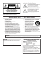 2
2
-
 3
3
-
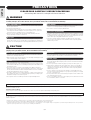 4
4
-
 5
5
-
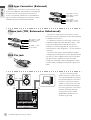 6
6
-
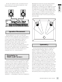 7
7
-
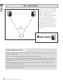 8
8
-
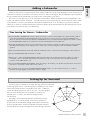 9
9
-
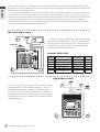 10
10
-
 11
11
-
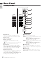 12
12
-
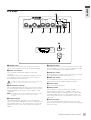 13
13
-
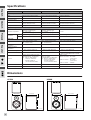 14
14
-
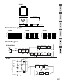 15
15
-
 16
16


en otros idiomas
- français: Yamaha D-7 Manuel utilisateur
- italiano: Yamaha D-7 Manuale utente
- English: Yamaha D-7 User manual
- Deutsch: Yamaha D-7 Benutzerhandbuch
- русский: Yamaha D-7 Руководство пользователя
- Nederlands: Yamaha D-7 Handleiding
- português: Yamaha D-7 Manual do usuário
- dansk: Yamaha D-7 Brugermanual
- polski: Yamaha D-7 Instrukcja obsługi
- čeština: Yamaha D-7 Uživatelský manuál
- svenska: Yamaha D-7 Användarmanual
- 日本語: Yamaha D-7 ユーザーマニュアル
- Türkçe: Yamaha D-7 Kullanım kılavuzu
- suomi: Yamaha D-7 Ohjekirja
- română: Yamaha D-7 Manual de utilizare
Artículos relacionados
-
Yamaha MSR800W El manual del propietario
-
Yamaha MSP5A Manual de usuario
-
Yamaha MSR400 El manual del propietario
-
Yamaha HS5 El manual del propietario
-
Yamaha n12 El manual del propietario
-
-
-
-
Yamaha SW10 El manual del propietario
-
Yamaha DXR10 El manual del propietario