Husky H100FS Manual de usuario
- Categoría
- Pistola de clavos
- Tipo
- Manual de usuario
Este manual también es adecuado para

OPERATOR’S MANUAL
18 GAUGE STAPLER
CALIBRE 18 GRAPADORA DE ACABAR
H100FS
Your stapler has been engineered and manufactured to
our high standard for dependability, ease of operation, and
operator safety. When properly cared for, it will give you
years of rugged, trouble-free performance.
WARNING: To reduce the risk of injury, the user
must read and understand the operator’s manual before
using this product.
Thank you for your purchase.
Su grapadora de acabar ha sido diseñada y fabricada de
conformidad con las estrictas normas para brindar fiabilidad,
facilidad de uso y seguridad para el operador. Con el debido
cuidado, le brindará muchos años de sólido y eficiente
funcionamiento.
ADVERTENCIA: Para reducir el riesgo de
lesiones, el usuario debe leer y comprender el manual
del operador antes de usar este producto.
Le agradecemos su compra.
SAVE THIS MANUAL FOR FUTURE REFERENCE
GUARDE ESTE MANUAL PARA FUTURAS CONSULTAS
1
2
3

2
TABLE OF CONTENTS
INTRODUCTION
This product has many features for making its use more pleasant and enjoyable. Safety, performance, and dependability
have been given top priority in the design of this product making it easy to maintain and operate.
* * *
Este producto ofrece numerosas características para hacer más agradable y placentero su uso. En el diseño de este producto
se ha conferido prioridad a la seguridad, el desempeño y la fiabilidad, por lo cual se facilita su manejo y mantenimiento.
Introduction ......................................................................................................................................................................2
Introducción
General Safety Rules ........................................................................................................................................................ 3
Reglas de seguridad generales
Specific Safety Rules .....................................................................................................................................................4-5
Reglas de seguridad específicas
Symbols ............................................................................................................................................................................ 6
Símbolos
Glossary ............................................................................................................................................................................ 7
Glosario
Features ............................................................................................................................................................................8
Características
Assembly .......................................................................................................................................................................... 9
Armado
Operation ..................................................................................................................................................................... 9-12
Funcionamiento
Maintenance ................................................................................................................................................................... 13
Mantenimiento ............................................................................................................................................................................... 13-14
Accessories .................................................................................................................................................................... 14
Accesorios
Troubleshooting .............................................................................................................................................................. 14
Corrección de problemas
Warranty ......................................................................................................................................................................... 15
Garantía
Figure numbers (illustrations) ....................................................................................................................................16-17
Figura numeras (ilustraciones)
Parts Ordering and Service ...............................................................................................................................Back Page
Pedidos de piezas y servicio ............................................................................................................................................Pág. posterior

3 – English
DANGER:
READ AND UNDERSTAND TOOL LABELS AND
MANUAL. Failure to follow warnings could result in
DEATH or SERIOUS INJURY.
SAVE THESE INSTRUCTIONS
WORK AREA
Keep your work area clean and well lit. Cluttered
benches and dark areas invite accidents.
Do not operate power tools in explosive atmospheres,
such as in the presence of flammable liquids, gases,
or dust. Power tools create sparks which may ignite the
dust or fumes.
Keep bystanders, children, and visitors away while
operating a power tool. Distractions can cause you to
lose control.
PERSONAL SAFETY
Eye protection which conforms to ANSI specifications
and provides protection against flying particles both
from the FRONT and SIDE should ALWAYS be worn
by the operator and others in the work area when
loading, operating or servicing this tool. Eye protection
is required to guard against flying fasteners and debris,
which could cause severe eye injury.
The employer and/or user must ensure that proper eye
protection is worn. We recommend Wide Vision Safety
Mask for use over eyeglasses or standard safety glasses
that provide protection against flying particles both from
the front and side. Always wear eye protection with side
shields marked to comply with ANSI Z87.1.
Additional safety protection will be required in some
environments. For example, the working area may in-
clude exposure to noise level which can lead to hearing
damage. The employer and user must ensure that any
necessary hearing protection is provided and used by the
operator and others in the work area. Some environments
will require the use of head protection equipment. When
required, the employer and user must ensure that head
protection conforming to ANSI Z89.1-1997 is used.
Stay alert, watch what you are doing and use common
sense when operating a power tool. Do not use tool
while tired or under the influence of drugs, alcohol,
or medication. A moment of inattention while operating
power tools may result in serious personal injury.
Dress properly. Do not wear loose clothing or jewelry.
Contain long hair. Keep your hair, clothing, and gloves
away from moving parts. Loose clothes, jewelry, or long
hair can be caught in moving parts.
Keep fingers away from trigger when not driving fas-
teners to avoid accidental firing.
Do not overreach. Keep proper footing and balance
at all times. Proper footing and balance enables better
control of the tool in unexpected situations.
Use safety equipment. Always wear eye protection.
Dust mask, nonskid safety shoes, hard hat, or hearing
protection must be used for appropriate conditions.
Do not use on a ladder or unstable support. Stable
footing on a solid surface enables better control of the
tool in unexpected situations.
TOOL USE AND CARE
Do not force tool. Use the correct tool for your
application. The correct tool will do the job better and
safer at the rate for which it is designed.
Do not use tool if trigger does not actuate properly.
Any tool that cannot be controlled with the trigger is
dangerous and must be repaired.
Check operation of the workpiece contact mechanism
frequently. Do not use the tool if the workpiece contact
mechanism is not working correctly as accidental driving
of a fastener may result. Do not interfere with the proper
operation of the workpiece contact mechanism.
Store idle tools out of the reach of children and other
untrained persons. Tools are dangerous in the hands of
untrained users.
Maintain tools with care. Follow maintenance instruc-
tions. Properly maintained tools are easier to control.
Check for misalignment or binding of moving parts,
breakage of parts, and any other condition that may
affect the tool’s operation. If damaged, have the tool
serviced before using. Many accidents are caused by
poorly maintained tools.
Use only fasteners that are recommended for your
model.
Keep the tool and its handle dry, clean and free from
oil and grease. Always use a clean cloth when clean-
ing. Never use brake fluids, gasoline, petroleum-based
products, or any strong solvents to clean your tool. Fol-
lowing this rule will reduce the risk of loss of control and
deterioration of the enclosure plastic.
SERVICE
Tool service must be performed only by qualified re-
pair personnel. Service or maintenance performed by
unqualified personnel may result in a risk of injury.
When servicing a tool, use only identical replacement
parts. Follow instructions in the Maintenance section
of this manual. Use of unauthorized parts or failure to fol-
low Maintenance instructions may create a risk of injury.
GENERAL SAFETY RULES

4 – English
SPECIFIC SAFETY RULES
Know your pneumatic tool. Read operator’s manual
carefully. Learn its applications and limitations, as well
as the specific potential hazards related to this tool. Fol-
lowing this rule will reduce the risk of electric shock, fire,
or serious injury.
Always wear eye protection with side shields marked
to comply with ANSI Z87.1. Failure to do so could result
in objects being thrown into your eyes resulting in possible
serious injury.
Protect your lungs. Wear a face or dust mask if the
operation is dusty. Following this rule will reduce the risk
of serious personal injury.
Protect your hearing. Wear hearing protection during
extended periods of operation. Following this rule will
reduce the risk of serious personal injury.
Make sure the hose is free of obstructions or snags.
Entangled or snarled hoses can cause loss of balance or
footing and may become damaged.
Use the tool only for its intended use. Do not discharge
fasteners into open air.
Use the pneumatic tool only for the purpose for which
it was designed.
Use only the fasteners recommended for this tool.
Use of the wrong fasteners could result in poor fastener
feeding, jammed fasteners, and fasteners leaving the tool
at erratic angles. If fasteners are not feeding smoothly
and properly, discontinue their use immediately. Jammed
and improperly feeding fasteners could result in serious
personal injury.
Never use this tool in a manner that could cause a
fastener to be directed toward anything other than
the workpiece.
Do not use the tool as a hammer.
Always carry the tool by the handle. Never carry the
tool by the air hose.
Do not alter or modify this tool from the original design
or function without approval from the manufacturer.
Always be aware that misuse and improper handling
of this tool can cause injury to yourself and others.
Never clamp or tape the trigger or workpiece contact
in an actuated position.
Never leave a tool unattended with the air hose at-
tached.
Do not operate this tool if it does not contain a legible
warning label.
Do not continue to use a tool that leaks air or does
not function properly.
OPERATION
Always assume that the tool contains fasteners.
Do not carry the tool from place to place holding the
trigger. Accidental discharge could result.
Always handle the tool with care:
• Respect the tool as a working implement.
• Neverengageinhorseplay.
• Neverpullthetriggerunlessnoseisdirectedtoward
the work.
• Keepothersasafedistancefromthetoolwhiletoolisin
operation as accidental actuation may occur, possibly
causing injury.
Choice of triggering method is important. Check
manual for triggering options.
Pneumatic tools are designed for single-hand use. Do
not hold the tool by the front of the magazine. Do not put
hands, head, or other parts of your body near the bottom
of the magazine where the fastener exits the tool, as seri-
ous personal injury could result.
Do not point the tool toward yourself or anyone
whether it contains fasteners or not.
When driving nails at an angle, make sure that the
tool is pointed away from yourself and others.
Do not actuate the tool unless you intend to drive a
fastener into the workpiece.
Always ensure that the workpiece contact is fully posi-
tioned above the workpiece. Positioning the workpiece
contact only partially above the workpiece could cause
the fastener to miss the workpiece completely and result
in serious personal injury.
Do not drive fasteners near edge of material. The
workpiece may split causing the fastener to ricochet,
injuring you or a co-worker. Be aware that the fastener
may follow the grain of the wood, causing it to protrude
unexpectedly from the side of the work material.
Keep hands and body parts clear of immediate work
area. Hold workpiece with clamps when necessary to
keep hands and body out of potential harm. Be sure the
workpiece is properly secured before pressing the fas-
tener against the material. The workpiece contact may
cause the work material to shift unexpectedly.
Keep face and body parts away from back of the tool
cap when working in restricted areas. Sudden recoil
can result in impact to the body, especially when nailing
into hard or dense material.

5 – English
SPECIFIC SAFETY RULES
During normal use the tool will recoil immediately
after driving a fastener. This is a normal function of
the tool. Do not attempt to prevent the recoil by holding
the nailer against the work. Restriction to the recoil can
result in a second fastener being driven from the nailer.
Grip the handle firmly, let the tool do the work and do not
place second hand on top of tool or near exhaust at any
time. Failure to heed this warning can result in serious
personal injury.
Do not drive fasteners on top of other fasteners or with
the tool at an overly steep angle as this may cause
deflection of fasteners which could cause injury.
Do not drive fasteners close to the edge of the
workpiece as the wood may split, allowing the fas-
tener to be deflected possibly causing injury.
AIR SUPPLY AND CONNECTIONS
Do not use oxygen, combustible gases or bottled
gases as a power source for this tool as tool will ex-
plode, possibly causing injury or death.
Do not use with an air compressor which can po-
tentially exceed 200 psi as tool may burst, possibly
causing injury.
The connector on the tool must not hold pressure
when air supply is disconnected. If an incorrect fitting
is used, the tool can remain charged with air after discon-
necting and thus will be able to drive a fastener even after
the air line is disconnected, possibly causing injury.
Always disconnect air supply:
• Beforemakingadjustments
• Whenservicingthetool
•Whenclearingajam
• Whentoolisnotinuse
• Whenmovingtoadifferentworkarea,asaccidental
actuation may occur, possibly causing injury.
LOADING TOOL
Do not load the tool with fasteners when any one of
the operating controls is activated.
When loading tool:
Never place a hand or any part of body in fastener
discharge area of tool.
Never point tool at anyone.
Do not pull the trigger or depress the workpiece
contact as accidental actuation may occur, possibly
causing injury.
SAVE THESE INSTRUCTIONS
Refer to them frequently and use them to instruct others
who may use this tool. If you loan someone this tool, loan
them these instructions also.

6 – English
SYMBOLS
CAUTION:
The following signal words and meanings are intended to explain the levels of risk associated with this product.
Indicates an imminently hazardous situation, which, if not avoided, will result in death
or serious injury.
Indicates a potentially hazardous situation, which, if not avoided, could result in death
or serious injury.
Indicates a potentially hazardous situation, which, if not avoided, may result in minor or
moderate injury.
(Without Safety Alert Symbol) Indicates a situation that may result in property damage.
SYMBOL SIGNAL MEANING
DANGER:
CAUTION:
WARNING:
Some of the following symbols may be used on this tool. Please study them and learn their meaning. Proper interpretation
of these symbols will allow you to operate the tool better and safer.
SYMBOL NAME DESIGNATION/EXPLANATION
Safety Alert Indicates a potential personal injury hazard
Read The Operator’s Manual
To reduce the risk of injury, user must read and understand operator’s
manual before using this product.
Eye Protection
Always wear eye protection with side shields marked to comply with
ANSI Z87.1.
Eye, Ear and Head Protection
Always wear eye protection with side shields marked to comply with ANSI
Z87.1, along with hearing and head protection when needed.
KeepHandsAway Keephandsandbodyawayfromthedischargeareaofthetool.
Hot Surface
To reduce the risk of injury or damage, avoid contact with any hot
surface.

7 – English
GLOSSARY OF TERMS
Activate (operating controls)
To move an operating control so that it is in a position that
allows the tool to be actuated or that satisfies one requirement
for the tool to be actuated.
Actuate (tool)
To cause movement of the tool component(s) intended to
drive a fastener.
Air inlet port
In an air tool, the opening to which the compressed air supply
is connected, usually by means of a threaded fitting.
Fastener
A staple, pin, brad, nail, or other fastening device which is
designed and manufactured for use in the tools within the
scope of this standard.
Jam
An obstruction in the feed or drive areas of the tool.
Maximum air pressure
The maximum allowable pressure of the compressed air, as
specified by the manufacturer, for operating a tool.
Operating control
A control that separately, or as part of an actuation system,
can cause the actuation of a tool.
Single sequential actuation
An actuation system in which there is more than one operating
control and the operating controls must be activated in a
specific sequence to actuate the tool. Additional actuation
can occur when a specific operating control, other than a
workpiece contact, is released and re-activated.
Trigger
A tool operating control activated by a tool operator’s fingers.
Workpiece
The intended object into which a fastener is to be driven
by a tool.
Workpiece contact
An operating control element or assembly on the tool intended
to be activated by the material to be fastened.

8 – English
FEATURES
PRODUCT SPECIFICATIONS
Operating Pressure.............................................70-120 psi
Fastener Type ....................18 gauge narrow crown staples
Fastener Range ............................................. 5/8 in. to 1 in.
Magazine Capacity ............................................100 staples
Air Consumption........................ 0.2949 ft
3
/cycle at 100 psi
Air Inlet .............................................................. 1/4 in. NPT
Weighted sound impulse power level ................... 95.5 dBA
Weight ................................................................... 2.98 lbs.
KNOW YOUR STAPLER
See Figure 1, page 15.
The safe use of this product requires an understanding of the
information on the product and in this operator’s manual as
well as a knowledge of the project you are attempting. Before
use of this product, familiarize yourself with all operating
features and safety rules.
ADJUSTABLE EXHAUST
Theexhaustcanbeadjusted360˚dependingonoperator
preference.
DEPTH OF DRIVE ADJUSTMENT
The tool-free depth of drive adjustment lets the operator
select precise driving depth of the fastener.
DUST CAP
The dust cap helps prevent dust and debris from entering
the quick-connect air fitting. Cover the air fitting with the
dust cap when not in use.
NO-MAR NOSEPIECE
The no-mar nosepiece prevents marring and denting when
using the tool on softer woods.
SIDE-LOADING MAGAZINE
The side-loading magazine allows easy three-step loading
of fasteners.
TRIGGER
Your stapler has a single sequential trigger for precise
fastener placement.

9 – English
ASSEMBLY
UNPACKING
This product has been shipped completely assembled.
Carefully remove the tool and any accessories from the
box. Make sure that all items listed in the packing list are
included.
WARNING:
Do not use this product if it is not completely assembled
or if any parts appear to be missing or damaged. Use of
a product that is not properly and completely assembled
could result in serious personal injury.
Inspect the tool carefully to make sure no breakage or
damage occurred during shipping.
Do not discard the packing material until you have care-
fully inspected and satisfactorily operated the tool.
If any parts are damaged or missing, please call
1-866-340-3912 for assistance.
PACKING LIST
Stapler
Sample Fasteners
Oil (If part of a multi tool kit only 1 oil bottle per combo)
HexKeys(3mmand4mm)
Operator’s Manual
WARNING:
If any parts are damaged or missing do not operate this
tool until the parts are replaced. Use of this product
with damaged or missing parts could result in serious
personal injury.
WARNING:
Do not attempt to modify this tool or create accessories
not recommended for use with this tool. Any such
alteration or modification is misuse and could result in a
hazardous condition leading to possible serious personal
injury.
OPERATION
DANGER:
Do not use oxygen, combustible gases or bottled gases
as a power source for this tool. The tool will explode and
cause death or serious injury.
WARNING:
Do not allow familiarity with tools to make you careless.
Remember that a careless fraction of a second is
sufficient to inflict severe injury.
WARNING:
Always wear eye protection with side shields marked to
comply with ANSI Z87.1. Failure to do so could result in
objects being thrown into your eyes resulting in possible
serious injury.
WARNING:
Disconnect the tool from the air supply before leaving the
work area, moving the tool to another location, or handing
the tool to another person. Failure to do so could result
in serious personal injury.
APPLICATIONS
You may use this tool for the purposes listed below:
Finish and Trim (Interior and Exterior)
Floor Underlayment
Cabinet Work
Casebacks
Furniture
Light Trim Moldings
Fascia and Soffits
Drawers
Staircases
Carpet installation
Mirror and Picture Frames
Crafts
Lattice

10 – English
WARNING:
Always wear eye protection. Eye protection does not fit all
operators in the same way. Make sure the eye protection
chosen has side shields or provides protection from flying
debris both from the front and sides.
PREPARING THE TOOL FOR USE
See Figure 2, page 15.
Under normal use conditions, the tool should be lubricated
before connecting the tool to an air supply. Add air tool oil
into the air fitting on the tool once daily with minimal use,
or twice a day with heavy use. Only a few drops of oil at a
time is necessary. Too much oil will only collect inside the
tool and will be noticeable in the exhaust cycle.
Before connecting the tool, check the air compressor gauge
to be sure it is functioning within the proper range of 70-
120 psi.
DUST CAP
See Figure 2, page 15.
The dust cap helps prevent dust and debris from entering
the air fitting. Cover the air fitting with the dust cap when
storing the tool.
NO-MAR NOSEPIECE
See Figure 3, page 15.
The no-mar nosepiece attached to the nose of the tool helps
prevent marring and denting when working with softer woods.
When requesting a replacement pad, request part number
079065001059.
WARNING:
Disconnect the tool from the air supply before removing
or replacing the no-mar nosepiece. Failure to do so could
result in serious personal injury.
The no-mar nosepiece can be removed by pulling it down and
away from the nose. To replace the no-mar nosepiece, fit it
into place over the nose and push up at the back to reseat.
OPERATION
ADJUSTING THE EXHAUST
See Figure 4, page 15.
The adjustable exhaust on the top cap of the tool allows
the operator to direct the exhaust according to operator
preference. To adjust, turn the exhaust cap until the exhaust
blows in the desired direction.
WARNING:
Disconnect the tool from the air supply before leaving the
work area, moving the tool to another location, or handing
the tool to another person. Failure to do so could result
in serious personal injury.
CONNECTING THE TOOL TO AN AIR SUPPLY
See Figure 5, page 15.
DANGER:
Do not use oxygen, combustible gases or bottled gases
as a power source for this tool. The tool will explode and
cause death or serious injury.
This tool is designed to operate on clean, dry compressed air
at regulated pressures between 70 and 120 psi. The correct
air pressure is the lowest pressure that will do the job.
NOTE: Air pressure that is higher than 120 psi may damage
the tool.
The tool and air hose must have a hose coupling that allows
all pressure to be removed from the tool when the coupling
is disconnected.
WARNING:
Always use a coupling that discharges all the compressed
air in the tool at the time the fitting or hose coupling is
disconnected. Using a coupling that does not discharge
the compressed air could cause unintended operation
and serious personal injury.
WARNING:
Do not climb rigging or scaffolding while carrying a tool
that is connected to an air hose. Doing so could result in
serious personal injury.
Connect the tool to the air supply with a 1/4 in. female quick
connector.

11 – English
OPERATION
LOADING THE TOOL WITH STAPLES
See Figure 6, page 15.
Connect the tool to the air supply.
WARNING:
The tool’s driving mechanism may cycle when the tool
is first connected to the air supply. Always connect the
tool to the air supply before loading staples to prevent
injury from unintended cycling. Always make sure the
tool’s magazine is empty at the beginning of each work
session, before connecting to an air supply.
WARNING:
Keep the tool pointed away from yourself and others
when loading fasteners. Failure to do so could result in
possible serious personal injury.
WARNING:
Use only the staples recommended for use with this
tool. The use of any other fasteners can result in tool
malfunction, leading to serious injuries.
WARNING:
Never load fasteners with the workpiece contact or
trigger activated. Doing so could result in possible serious
personal injury.
Pushthe magazine latch to release and open the
magazine.
With the nose of the tool pointed away from you, insert a
strip of staples into the magazine. Staples must always
be inserted with the points down, fitting over the staple
track.
To close the magazine, push it forward until the latch
clicks into place.
Makesurethe magazine issecurelylockedintoplace
before driving a staple.
DRIVING A FASTENER
See Figure 7, page 16.
WARNING:
Never wedge or hold back the workpiece contact
mechanism during operation of the tool. Doing so could
result in possible serious injury.
SINGLE SEQUENTIAL ACTUATION
Single sequential actuation provides accurate fastener
placement.
Connect the tool to the air supply.
Grip the tool firmly to maintain control. Position the nose
of the tool onto the work surface.
Push the tool against the work surface to depress the
workpiece contact.
Pull the trigger to drive a fastener.
Allow the tool to recoil away from the work surface as the
fastener is driven.
WARNING:
During normal use the tool will recoil immediately
after driving a fastener. This is a normal function of
the tool. Do not attempt to prevent the recoil by holding
the stapler against the work. Restriction to the recoil can
result in a second fastener being driven from the stapler.
Grip the handle firmly, let the tool do the work, and do
not place second hand on top of tool or near exhaust at
any time. Failure to heed this warning can result in serious
personal injury.
SETTING THE AIR PRESSURE
The amount of air pressure required will depend on the size
of the fastener and the workpiece material.
Begin testing the depth of drive by driving a test fastener into
the same type of workpiece material used for the actual job.
Drive a test fastener with the air pressure set at 90-95 psi.
Raise or lower the air pressure to find the lowest setting that
will perform the job with consistent results.
It may be possible to achieve the desired depth with air
pressure adjustments alone. If finer adjustments are needed,
use the drive depth adjustment on the tool.

12 – English
DRIVE DEPTH ADJUSTMENT
See Figure 8, page 16.
The driving depth of the fastener may be adjusted. It is
advisable to test the depth on a scrap workpiece to determine
the required depth for the application.
To determine depth of drive, first adjust the air pressure and
drive a test fastener. To achieve the desired depth, use the
drive depth adjustment on the tool.
Disconnect the tool from the air supply.
Turn the depth selector left or right to change the driving
depth.
Reconnect the tool to the air supply.
Drive a test fastener after each adjustment until the
desired depth is set.
WARNING:
Disconnect the tool from the air supply before removing
fasteners. Failure to do so could result in serious personal
injury.
REMOVING FASTENERS FROM THE TOOL
See Figure 9, page 16.
Disconnect the tool from the air supply.
To remove a strip of staples from the tool, depress the
latch located at the rear of the magazine and slide the
magazine open.
Remove the strip of staples.
To close the magazine, push it forward until the latch
clicks into place.
OPERATION
WARNING:
Disconnect the tool from the air supply before clearing a
jammed fastener. Failure to do so could result in serious
personal injury.
CLEARING A JAMMED FASTENER
See Figures 10 - 12, page 16.
If a staple or fastener becomes jammed in the tool:
Disconnect the air hose and keep the tool pointed away
from you while clearing the jam.
Remove staples or fasteners from the magazine.
Pull up on the jam release latch to open it. This may clear
the jam.
If there is still a jam, use a flat blade screwdriver to push
the driver blade back, freeing the jammed fastener.
Remove the bent fastener.
Reconnect the tool to the air supply.
Reinsert fasteners and close the magazine.

13 – English
MAINTENANCE
NOTE: Some commercial air line drying liquids are harmful
to “O” rings and seals. Do not use these low temperature
air dryers without checking compatibility.
AIR SUPPLY PRESSURE AND VOLUME
Air volume is as important as air pressure. The air volume
supplied to the tool may be inadequate because of undersize
fittings and hoses, or from the effects of dirt and water in the
system. Restricted air flow will prevent the tool from receiving
an adequate volume of air, even though the pressure reading
is high. The results will be a slow operation or reduced
driving power. Before evaluating tool problems for these
symptoms, trace the air supply from the tool to the supply
source for restrictive connectors, low points containing
water and anything else that would prevent full volume flow
of air to the tool.
REQUIRED DAILY CHECKLIST
Disconnect the air supply from the tool and remove all
fasteners.
Check all screws, nuts, bolts, and pins on the tool. If
any of these are loose, they must be tightened with the
appropriate size wrench.
Press the workpiece contact against a workpiece to
ensure that it moves smoothly.
With the workpiece contact depressed, pull the trigger.
The trigger should move smoothly, without binding.
While the tool is not loaded, connect the appropriate air
supply (at 70 psi) to the tool.
Without pulling the trigger, press the workpiece contact
against a workpiece several times. The tool must not
operate. No air should leak from the tool.
With the workpiece contact not engaged on the
workpiece, point the tool down and away and pull the
trigger several times. Hold the trigger in this position for
a minimum of 5 seconds. The tool must not operate.
Press the workpiece contact firmly against the
workpiece. Pull the trigger. The tool must operate.
With the workpiece contact still depressed, release the
trigger. The driver must return to its up position.
If the tool successfully meets all the requirements in this
checklist, it is ready for use. Load the proper fasteners
for the desired application.
Set the depth of drive according to the Drive Depth
Adjustment section in this manual. Repeat this checklist
before using the tool each day, or if the tool is dropped
or damaged in any way.
WARNING:
When servicing use only identical replacement parts.
Use of any other parts may create a hazard or cause
product damage.
WARNING:
Always wear eye protection with side shields marked to
comply with ANSI Z87.1. Failure to do so could result in
objects being thrown into your eyes resulting in possible
serious injury.
WARNING:
Disconnect the tool from the air supply before performing
maintenance. Failure to do so could result in serious
personal injury.
GENERAL MAINTENANCE
Avoid using solvents when cleaning plastic parts. Most
plastics are susceptible to damage from various types of
commercial solvents and may be damaged by their use. Use
clean cloths to remove dirt, dust, oil, grease, etc.
WARNING:
Do not at any time let brake fluids, gasoline, petroleum-
based products, penetrating oils, etc., come in contact
with plastic parts. Chemicals can damage, weaken or
destroy plastic which may result in serious personal injury.
LUBRICATION
Frequent,butnotexcessive,lubricationisrequiredforbest
performance. Oil for pneumatic fastening tools added through
the air line connection will lubricate the internal parts. Do
not use detergent oil or additives as these lubricants will
cause accelerated wear to the seals and bumpers in the
tool, resulting in poor tool performance and frequent tool
maintenance.
COLD WEATHER OPERATION
For cold weather operation, near and below freezing, the
moisture in the air line may freeze and prevent tool operation.
We recommend the use of air tool lubricant or permanent
antifreeze (ethylene glycol) as a cold weather lubricant.
CAUTION:
Do not store tools in a cold weather environment to
prevent frost or ice formation on the tools’ operating
valves and mechanisms that could cause tool failure.

14 – English
ACCESSORIES
WARNING:
Current attachments and accessories available for use with this tool are listed above. Do not use any attachments or
accessories not recommended by the manufacturer of this tool. The use of attachments or accessories not recommended
can result in serious personal injury.
To order parts and maintenance kits, call 1-866-340-3912.
OverhaulKit ......................................................................................................................................................079065001255
DriverMaintenanceKit .....................................................................................................................................079065001256
DriverAssemblyKit ..........................................................................................................................................079065001257
OilandWrenchKit............................................................................................................................................079065001254
TROUBLESHOOTING
PROBLEM POSSIBLE CAUSE SOLUTION
Air leak near the top of the tool or
in the trigger area
Loose screws
Worn or damaged O-rings or seals
Tighten screws
InstallOverhaulKit
Air leak near the bottom of the
tool
Loose screws
Worn or damaged O-rings or bumper
Tighten screws
InstallOverhaulKit
Tool does nothing or operates
sluggishly
Inadequate air supply
Inadequate lubrication
Worn or damaged O-rings or bumper
Verify adequate air supply
Lubricate tool
InstallOverhaulKit
Tool jams frequently Incorrect fasteners
Damaged fasteners
Loose magazine
Dirty magazine
Worn or damaged driver
Verify that fasteners are the correct size
Replace fasteners
Tighten screws
Clean magazine
InstallDriverMaintenanceKit

15
WARRANTY
LIMITED WARRANTY STATEMENT
One World Technologies, Inc. warrants to the original retail
purchaser that this One World Technologies, Inc. product is
free from defect in material and workmanship and agrees
to repair or replace, at One World Technologies, Inc.’s
discretion, any defective product free of charge within
these time periods from the date of purchase.
Two years if the product is used for personal, family or
household use;
90 days, if used for any other purpose, such as
commercial or rental.
This warranty extends to the original retail purchaser
only and commences on the date of the original retail
purchase.
Any part of the One World Technologies, Inc. product
manufactured or supplied by One World Technologies,
Inc. and found in the reasonable judgment of One World
Technologies, Inc. to be defective in material or workmanship
will be repaired or replaced by an authorized One World
Technologies, Inc. service dealer without charge for parts
and labor.
The product, including any defective part, must be returned
to an authorized service dealer within the warranty period.
The expense of delivering the One World Technologies, Inc.
product to the dealer for warranty work and the expense of
returning it back to the owner after repair or replacement
will be paid by the owner. One World Technologies, Inc.’s
responsibility in respect to claims is limited to making the
required repairs or replacements and no claim of breach
of warranty shall be cause for cancellation or rescission of
the contract of sale of any One World Technologies, Inc.
product. Proof of purchase will be required by the dealer
to substantiate any warranty claim. All warranty work must
be performed by an authorized One World Technologies,
Inc. service dealer.
This warranty is limited to ninety (90) days from the date
of original retail purchase for any One World Technologies,
Inc. product that is used for rental or commercial purposes,
or any other income-producing purpose.
This warranty does not cover any One World Technologies,
Inc. product that has been subject to misuse, neglect,
negligence, or accident, or that has been operated in any
way contrary to the operating instructions as specified in
this operator’s manual. This warranty does not apply to
any damage to the One World Technologies, Inc. product
that is the result of improper maintenance or to any One
World Technologies, Inc. product that has been altered
or modified. The warranty does not extend to repairs
made necessary by normal wear or by the use of parts
or accessories which are either INCOMPATIBLE WITH
THE ONE WORLD TECHNOLOGIES, INC. product or
adversely affect its operation, performance, or durability.
One World Technologies, Inc. reserves the right to change
or improve the design of any One World Technologies, Inc.
product without assuming any obligation to modify any
product previously manufactured.
ALL IMPLIED WARRANTIES ARE LIMITED IN DURATION
TO THE STATED WARRANTY PERIOD. ACCORDINGLY,
ANY SUCH IMPLIED WARRANTIES INCLUDING
MERCHANTABILITY, FITNESS FOR A PARTICULAR
PURPOSE, OR OTHERWISE, ARE DISCLAIMED IN
THEIR ENTIRETY AFTER THE EXPIRATION OF THE
APPROPRIATE TWO-YEAR, ONE-YEAR, OR NINETY DAY
WARRANTY PERIOD. ONE WORLD TECHNOLOGIES,
INC.’S OBLIGATION UNDER THIS WARRANTY IS
STRICTLY AND EXCLUSIVELY LIMITED TO THE REPAIR
OR REPLACEMENT OF DEFECTIVE PARTS AND ONE
WORLD TECHNOLOGIES, INC. DOES NOT ASSUME
OR AUTHORIZE ANYONE TO ASSUME FOR THEM
ANY OTHER OBLIGATION. SOME STATES DO NOT
ALLOW LIMITATIONS ON HOW LONG AN IMPLIED
WARRANTY LASTS, SO THE ABOVE LIMITATION MAY
NOT APPLY TO YOU. ONE WORLD TECHNOLOGIES,
INC. ASSUMES NO RESPONSIBILITY FOR INCIDENTAL,
CONSEQUENTIAL, OR OTHER DAMAGES INCLUDING,
BUT NOT LIMITED TO, EXPENSE OF RETURNING THE
ONE WORLD TECHNOLOGIES, INC. PRODUCT TO AN
AUTHORIZED SERVICE DEALER AND EXPENSE OF
DELIVERINGIT BACK TO THE OWNER, MECHANIC’S
TRAVEL TIME, TELEPHONE OR TELEGRAM CHARGES,
RENTAL OF A LIKE PRODUCT DURING THE TIME
WARRANTY SERVICE IS BEING PERFORMED, TRAVEL,
LOSS OR DAMAGE TO PERSONAL PROPERTY, LOSS
OF REVENUE, LOSS OF USE OF THE PRODUCT,
LOSS OF TIME, OR INCONVENIENCE. SOME STATES
DO NOT ALLOW THE EXCLUSION OR LIMITATION OF
INCIDENTAL OR CONSEQUENTIAL DAMAGES, SO THE
ABOVE LIMITATION OR EXCLUSION MAY NOT APPLY
TO YOU.
This warranty gives you specific legal rights, and you may
also have other rights which vary from state to state.
This warranty applies to all One World Technologies,
Inc. products manufactured or supplied by One World
Technologies, Inc. and sold in the United States and
Canada.
To locate your nearest service dealer, dial
1-866-340-3912.
NOTE: FIGURES (ILLUSTRATIONS) START ON PAGE 16
AFTER SPANISH LANGUAGE SECTION.

NOTES

3 – Español
REGLAS DE SEGURIDAD GENERALES
PELIGRO:
LEA Y COMPRENDA LAS ETIQUETAS DE LAS
HERRAMIENTAS Y EL MANUAL. La inobservancia de
los avisos de advertencia podría causar la MUERTE o
LESIONES SERIAS.
GUARDE ESTAS INSTRUCCIONES
ÁREA DE TRABAJO
Mantenga limpia y bien iluminada el área de trabajo. Una
mesa de trabajo mal despejada y una mala iluminación son
causas comunes de accidentes.
No utilice herramientas motorizadas en atmósferas
explosivas, como las existentes alrededor de líquidos,
gases y polvos inflamables. Las herramientas eléctricas
generan chispas que pueden encender el polvo y los vapores
inflamables.
Mantenga alejados a los circunstantes, niños y demás
presentes al utilizar una herramienta eléctrica. Toda
distracción puede causar la pérdida del control de la
herramienta.
SEGURIDAD PERSONAL
Al cargar, utilizar y dar servicio a esta herramienta, el
operador y demás personas SIEMPRE deben llevar puesta
protección ocular que cumpla con las especificaciones
ANSI y ofrezca protección contra partículas que salgan
disparadas del FRENTE y de los LADOS. Se requiere
protección ocular como protección contra sujetadores y
desechos que salgan disparados, los cuales pueden causar
lesiones oculares serias.
Tanto el patrón como el operador deben asegurarse de que
se use protección ocular adecuada. Recomendamos la careta
protectora de visión amplia encima de los anteojos normales o
de los anteojos de seguridad que ofrecen protección frontal y
lateral contra partículas que salen disparadas. Siempre póngase
protección ocular con la marca de cumplimiento de la norma
ANSI Z87.1.
En algunos entornos se requiere protección adicional. Por
ejemplo, en el área de trabajo puede haber exposición a un
nivel de ruido que puede dañar el oído. El patrón y el operador
deben asegurarse de contar con toda la protección auditiva
necesaria y de que sea usada por el operador mismo y demás
personas presentes en el área de trabajo. En algunos entornos
se requiere el uso de equipo de protección para la cabeza.
Cuando se requiera, el patrón y el operador deben asegurarse
de que la protección usada para la cabeza cumpla con la norma
ANSI Z89.1-1997.
Permanezca alerta, preste atención a lo que esté haciendo y
aplique el sentido común al utilizar herramientas eléctricas.
No utilice la herramienta si está cansado o se encuentra
bajo los efectos de alguna droga, alcohol o medicamento.
Un momento de inatención al utilizar una herramienta eléctrica
puede causar lesiones corporales serias.
Vístase adecuadamente. No vista ropas holgadas ni joyas.
Recójase el cabello si está largo. Mantenga el cabello, la
ropa y los guantes alejados de las piezas móviles. Las ropas
holgadas, las joyas y el cabello largo pueden engancharse en
las piezas móviles.
Para evitar disparar accidentalmente la herramienta,
mantenga los dedos lejos del gatillo cuando no esté
clavando.
No estire el cuerpo para alcanzar mayor distancia. Mantenga
una postura firme y buen equilibrio en todo momento. La
postura firme y el buen equilibrio permiten un mejor control de
la herramienta en situaciones inesperadas.
Use equipo de seguridad. Siempre póngase protección
ocular. Cuando lo exijan las circunstancias debe ponerse careta
contra el polvo, zapatos de seguridad antiderrapantes, casco
o protección auditiva.
No utilice la unidad al estar en una escalera o en un soporte
inestable. Una postura estable sobre una superficie sólida
permite un mejor control de la herramienta en situaciones
inesperadas.
EMPLEO Y CUIDADO DE LA HERRAMIENTA
No fuerce la herramienta. Utilice la herramienta adecuada
al trabajo. La herramienta adecuada efectúa mejor y de manera
más segura el trabajo, si además se maneja a la velocidad para
la que está diseñada.
No utilice la herramienta si no funciona correctamente el
gatillo. Una herramienta que no pueda controlarse con el gatillo
es peligrosa y debe repararse.
Verifique con frecuencia el funcionamiento del mecanismo
del disparador de contacto. No use la herramienta si no está
funcionando correctamente el mecanismo del disparador de
contacto, ya que puede causarse por accidente el disparo
de un sujetador. No interfiera en el funcionamiento normal del
mecanismo del disparador de contacto.
Guarde las herramientas que no estén en uso fuera del
alcance de los niños y de toda persona no capacitada en el
uso de las mismas. Las herramientas son peligrosas en manos
de personas no capacitadas en el uso de las mismas.
Dé mantenimiento con cuidado a las herramientas. Siga
todas las instrucciones de mantenimiento. Las herramientas
que han recibido el debido mantenimiento se controlan con
mayor facilidad.
Revise para ver si hay desalineación o atoramiento de piezas
móviles, ruptura de piezas o toda otra condición que pueda
afectar el funcionamiento de la herramienta. Si se daña la
herramienta, llévela a servicio antes de volver a utilizarla.
Numerosos accidentes son causados por herramientas mal
cuidadas.
Sólo utilice los sujetadores (clavos o grapas, según sea el
caso) recomendados para cada modelo en particular.
Mantenga la herramienta y el mango secos, limpios y sin
aceite ni grasa. Siempre utilice un paño limpio para la limpieza
de la unidad. Nunca utilice fluidos para frenos, gasolina,
productos a base de petróleo ni solventes fuertes para limpiar
la herramienta. Con el cumplimiento de esta regla se reduce el
riesgo de una pérdida de control y el deterioro del alojamiento
de plástico de la unidad.
SERVICIO
El servicio de la herramienta sólo debe ser efectuado
por personal de reparación calificado. Todo servicio o
mantenimiento efectuado por personal no calificado puede
significar un riesgo de lesiones.
Al dar servicio a una herramienta, sólo utilice piezas de
repuesto idénticas. Siga las instrucciones señaladas en la
sección Mantenimiento de este manual. El empleo de piezas
no autorizadas o el incumplimiento de las instrucciones de
mantenimiento puede significar un riesgo de lesiones.

4 – Español
REGLAS DE SEGURIDAD ESPECÍFICAS
Familiarícese con su herramienta neumáticas. Lea
cuidadosamente el manual del operador. Aprenda sus usos
y limitaciones, así como los posibles peligros específicos
de esta herramienta. Con el cumplimiento de esta regla se
reduce el riesgo de una descarga eléctrica, incendio o lesión
seria.
Siempre use gafas de seguridad con protección lateral.
Los anteojos comunes sólo tienen lentes resistentes
a los impactos. NO son anteojos de seguridad. Con el
cumplimiento de esta regla se reduce el riesgo de posibles
lesiones oculares.
Protéjase los pulmones. Use una careta o mascarilla
contra el polvo si la operación genera mucho polvo. Con el
cumplimiento de esta regla se reduce el riesgo de lesiones
corporales serias.
Protéjase los oídos. Durante períodos prolongados de
utilización de la unidad póngase protección para los oídos.
Con el cumplimiento de esta regla se reduce el riesgo de
lesiones corporales serias.
Asegúrese de que la manguera no esté obstruida
ni enganchada. Si la manguera se enreda o engancha
puede causar una pérdida del equilibrio o postura y puede
dañarse.
Solamente utilice esta herramienta para el propósito
especificado. No dispare clavos al aire.
Use la herramienta neumática solamente para el
propósito para el que fue diseñada.
Solamente utilice los sujetadores recomendados para
esta herramienta. El uso de los sujetadores incorrectos
podría hacer que los sujetadores no avancen bien, que se
atoren y que los clavos no salgan de la herramienta siempre
al mismo ángulo. Si los sujetadores no avanzan de manera
uniforme y correcta, interrumpa su uso de inmediato. Los
sujetadores atorados que avanzan de manera incorrecta
pueden provocar lesiones serias.
Nunca utilice esta herramienta de ninguna forma que
pueda dirigir un sujetador (clavo o grapa, según sea el
caso) hacia ninguna otra cosa que no sea la pieza de
trabajo.
No use la herramienta como martillo.
Siempre porte la herramienta por el mango. Nuna porte
la herramienta por la manguera de aire.
No altere ni modifique esta herramienta con respecto al
diseño o funcionamiento original sin la aprobación del
fabricante.
Siempre tenga presente que el uso y manejo indebidos
de esta herramienta puede causarle lesiones a usted y
a otras personas.
Nunca sujete con prensa o cinta adhesiva el gatillo
ni el disparador de contacto en la posición de
accionamiento.
Nuna deje desatendida ninguna herramienta con la
manguera de aire conectada.
No utilice esta herramienta si no tiene una etiqueta de
advertencia.
No continúe usando ninguna herramienta que tenga
fugas de aire o que no funcione correctamente.
FUNCIONAMIENTO
Siempre suponga que la herramienta contiene
sujetadores.
No traslade la herramienta de un lugar a otro con el dedo
en el gatillo. Podría producirse un disparo accidental.
Siempre maneje con cuidado la herramienta:
• Respetelaherramientacomounelementodetrabajo.
• Nuncaparticipeenjugueteos.
• Nuncatiredel gatillo a menos que la punta de la
herramienta esté dirigida hacia la superficie de trabajo.
• Mantengaalasdemáspersonasaunadistanciasegura
de la herramienta mientras esté utilizándose ésta ya que
puede ocurrir un accionamiento accidental de la misma,
y posibles lesiones.
Es importante el método de disparo elegido. Estudie el
manual, en el cual se describen las diferentes formas de
disparar.
Las herramientas neumáticas están diseñadas para
usarlas con una sola mano. No sujete la herramienta por
el frente del cargador. No ponga las manos, la cabeza ni
ninguna otra parte del cuerpo cerca de la parte inferior del
cargador, por donde salen los clavos de la herramienta, ya
que se pueden producir lesiones serias.
No apunte la herramienta hacia usted mismo ni a ninguna
otra persona, ya sea que contenga sujetadores (clavos
o grapas, según sea el caso) o no.
Cuando clava clavos en ángulo, asegúrese de que la her-
ramienta esté apuntando en dirección opuesta a donde
se encuentran usted y otras personas.
No accione la herramienta a menos que esté firmemente
colocada contra la pieza de trabajo.
Siempre asegúrese de que el elemento de contacto con
la pieza de trabajo esté totalmente coloca encima de
ella. Colocar el elemento de contacto con la pieza de trabajo
solamente de manera parcial encima de ella podría causar
que el sujetador no se introduzca en la pieza de trabajo por
completo y provoque lesiones serias.
No introduzca clavos cerca del borde del material.
La pieza de trabajo puede partirse y causar que el clavo
rebote y lesione a un compañero de trabajo. Tenga presente
que el clavo puede seguir la fibra de la madera y salir
inesperadamente por un lado de la pieza de trabajo.
Mantenga las manos y todas las partes del cuerpo lejos
del área de trabajo inmediata. Sujete firmemente la pieza
de trabajo con prensas de mano cuando sea necesario para
proteger las manos y el cuerpo de todo posible peligro.
Asegúrese de que la pieza de trabajo esté debidamente
asegurada antes de presionar la clavadora contra el material.
El disparador de contacto puede causar un movimiento
inesperado de la pieza de trabajo.

5 – Español
REGLAS DE SEGURIDAD ESPECÍFICAS
Mantenga la cara y las demás partes del cuerpo lejos
de la tapa de la herramienta al trabajar en espacios
limitados. En una retracción súbita la herramienta puede
golpear el cuerpo, especialmente al clavar en material duro
o denso.
Durante el uso normal de la herramienta, ésta se retrae
de inmediato después de introducir un sujetador. Así es
el funcionamiento normal de la herramienta. No intente
impedir la retracción presionando la clavadora contra la
pieza de trabajo. Toda restricción impuesta a la retracción
puede producir la impulsión de un segundo sujetador en
la clavadora. Sujete firmemente el mango, permita a la
herramienta que haga el trabajo y no coloque la otra mano
encima de la herramienta ni cerca del escape de aire en
ningún momento. La inobservancia de esta advertencia
puede causar lesiones corporales serias.
No introduzca sujetadores encima de otros, ni con la
herramienta a un ángulo excesivamente pronunciado, ya
que esto puede causar la desviación de los sujetadores
y con ello posibles lesiones.
No introduzca sujetadores cerca del borde de la pieza
de trabajo, ya que puede partirse la madera con lo cual
podría desviarse el sujetador y causar lesiones.
SUMINISTRO DE AIRE Y CONEXIONES
No utilice oxígeno, gases combustibles ni gases
embotellados como fuente de energía para esta
herramienta, ya que puede explotar y causar lesiones o
la muerte.
No use compresores de aire que puedan excederse de
200 psi, de presión ya que la herramienta puede estallar
y causar lesiones.
El conector de la herramienta debe no conservar presión
una vez desconectado el suministro de aire. Si se utiliza
una conexión inadecuada, la herramienta puede permanecer
cargada de aire después de desconectarla del suministro de
aire y por lo tanto con capacidad de impulsar un sujetador
y de causar lesiones.
Siempre desconecte el suministro de aire:
• Antesdeefectuarajustes
• Aldarservicioalaherramienta
•Aldespejarunatoramiento
• cuandonoestáusándoselaunidad
• Altrasladarseaunáreadetrabajodiferente,yaquepuede
accionarse accidentalmente la herramienta y causar
lesiones.
CÓMO CARGAR LA HERRAMIENTA
No cargue los sujetadores en la herramienta cuando
esté activado cualquiera de los controles de operación
de la misma.
Al cargar la herramienta:
Nunca coloque las manos ni ninguna parte del cuerpo
en el área de la herramienta donde sale disparado el
sujetador (clavo o grapa, según sea el caso).
Nunca apunte la herramienta a nadie.
No tire del gatillo ni oprima el disparador de contacto, ya
que puede accionarse accidentalmente la herramienta
y causar lesiones.
GUARDE ESTAS INSTRUCCIONES
Consúltelas con frecuencia y empléelas para instruir a otras
personas que puedan utilizar esta herramienta. Si presta a
alguien esta herramienta, facilítele también las instrucciones.

6 – Español
SÍMBOLOS
Es posible que se empleen en esta herramienta algunos de los siguientes símbolos. Le suplicamos estudiarlos y aprender su
significado. Una correcta interpretación de estos símbolos le permitirá utilizar mejor y de manera más segura la herramienta.
SYMBOL NAME DESIGNATION/EXPLANATION
Alerta de seguridad Indica un peligro posible de lesiones personales.
Lea el manual del operador
Para reducir el riesgo de lesiones, el usuario debe leer y comprender el manual del
operador antes de usar este producto.
Protección ocular
Siempre póngase protección ocular con protección lateral con la marca de
cumplimiento de la norma ANSI Z87.1.
Protección para los ojos, los
oídos y la cabeza
Siempre póngase protección ocular con protección lateral con la marca de
cumplimiento de la norma ANSI Z87.1 junto con protección para los oídos y la
cabeza que la necesite.
Mantenga lejos las manos
Mantenga las manos y el resto del cuerpo lejos del área de la herramienta por donde
sale disparado el sujetador.
Superficie caliente
Para reducir el riesgo de lesiones corporales o daños materiales evite tocar toda
superficie caliente.
Las siguientes palabras de señalización y sus significados tienen el objeto de explicar los niveles de riesgo relacionados con
este producto.
SÍMBOLO SEÑAL SIGNIFICADO
PELIGRO:
Indica una situación peligrosa inminente, la cual, si no se evita, causará la muerte
o lesiones serias.
ADVERTENCIA:
Indica una situación peligrosa posible, la cual, si no se evita, podría causar la
muerte o lesiones serias.
PRECAUCIÓN:
Indica una situación peligrosa posible, la cual, si no se evita, podría causar
lesiones menores o leves.
PRECAUCIÓN:
(Sin el símbolo de alerta de seguridad) Indica una situación que puede producir
daños materiales.

7 – Español
GLOSARIO DE TÉRMINOS
Activar (los controles de accionamiento)
Es mover un control de accionamiento de manera que quede
en una posición en la cual se accione la herramienta o cumpla
con un requisito necesario para accionar la misma.
Accionar (la herramienta)
Es producir el movimiento de los componentes de la
herramienta específicos para introducir un sujetador (clavo o
grapa, según sea el caso).
Conexión de entrada de aire
Refiriéndose a herramientas neumáticas, es la abertura a la
cual se conecta el suministro de aire comprimido, normalmente
por medio de un conectador roscado.
Sujetador
Es una grapa, clavo, puntilla o cualquier otra pieza de unión
diseñada y fabricada para utilizarse en las herramientas de
este tipo.
Atoramiento
Es una obstrucción en las zonas de alimentación o introducción
de sujetadores de la herramienta.
Presión de aire máxima
Es la presión máxima permitida del aire comprimido, según
las especificaciones del fabricante para la utilización de una
herramienta.
Control de accionamiento
Es un control que, por separado o como parte de un sistema
de accionamiento de una herramienta, sirve para accionarla.
Accionamiento secuencial sencillo
Es un sistema de accionamiento en el cual hay más de
un control de accionamiento y éstos deben ser activados
en una secuencia específica para accionar la herramienta.
Puede ocurrir un accionamiento adicional cuando un control
de accionamiento específico, que no sea el disparador de
contacto, se suelta y se vuelve a activar.
Gatillo
Es un control de accionamiento de una herramienta el cual
maneja con los dedos el operador.
Pieza de trabajo
Es el objeto específico en el cual se introduce un sujetador
(clavo o grapa, según sea el caso) con una herramienta.
Disparador de contacto
Es un elemento de control de accionamiento o un conjunto
de tales elementos, el cual es activado al tocar el material en
el que va a introducirse el sujetador.

8 – Español
CARACTERÍSTICAS
ESPECIFICACIONES DEL PRODUCTO
Presión de funcionamiento .............................. de 70-120 psi
Tipo de sujetador ..............Clavos de acabado de calibre 18
Gama de sujetadores:
................. 15,87 mm (5/8 pulg.) - 31,75 mm (1-1/4 pulg.)
Capacidad del cargador ....................................... 100 clavos
Consumo de aire ..................... 0,02949 pies
3
/ciclo a 100 psi
Entrada de aire ................................................ 1/4 pulg. NPT
Nivel de potencia ponderado
del impulso de sonido .............................................97,3 dBA
Peso .............................................................1,35 kg (2,98 lb)
FAMILIARÍCESE CON LA GRAPADORA
DE ACABAR
Vea la figura 1, página 15.
Para usar este producto con la debida seguridad se debe
comprender la información indicada en la herramienta misma
y en este manual, y se debe comprender también el trabajo
que intenta realizar. Antes de usar este producto, familiarícese
con todas las características de funcionamiento y normas de
seguridad del mismo.
ESCAPE AJUSTABLE
Elescapepuedeajustarse360˚,segúnlaspreferenciasdel
operador.
AJUSTE DE LA PROFUNDIDAD
DE INTRODUCCIÓN
El ajuste de la profundidad de introducción no requiere
herramientas y permite al operador ajustar con precisión la
profundidad de introducción del sujetador.
TAPA GUARDAPOLVO
La tapa guardapolvo ayuda a evitar que el polvo y la suciedad
entren en la conexión de aire. Cubra la conexión de aire
con la tapa guardapolvo cuando la herramienta no esté en
funcionamiento.
ALMOHADILLA PROTECTORA
La almohadilla protectora evita dañar y marcar las maderas
suaves con la herramienta.
CARGADOR DE CARGA LATERAL
El cargador de carga lateral puede cargarse fácilmente de
sujetadores (puntillas, clavos o grapas, según sea el caso)
en tres pasos.
GATILLO
El gatillo se ajusta automáticamente al modo de accionamiento
secuencial sencillo para la colocación precisa de los
sujetadores.

9 – Español
LISTA DE EMPAQUETADO
Clavadora de puntillas
Sujetadores de muestra
Aceite (Si forma parte del juego de la multiherramienta, se
utiliza 1 botella de aceite por juego)
Llave hexagonal (3 mm y 4 mm)
Manual del operador
ADVERTENCIA:
Si hay piezas dañadas o faltantes, no utilice esta
herramienta sin haber reemplazado las piezas dañadas
o faltantes. La inobservancia de esta advertencia puede
causar lesiones graves.
ADVERTENCIA:
No intente modificar esta herramienta ni hacer accesorios
no recomendados para la misma. Cualquier alteración o
modificación constituye maltrato el cual puede causar
una condición peligrosa, y como consecuencia posibles
lesiones corporales serias.
ARMADO
DESEMPAQUETADO
Embarcamos este producto completamente armado.
Extraiga cuidadosamente de la caja la herramienta y los
accesorios. Asegúrese de que estén presentes todos los
artículos enumerados en la lista de empaquetado.
ADVERTENCIA:
No use este producto si no está totalmente ensamblado o
si alguna pieza falta o está dañada. Si utiliza un producto
que no se encuentra ensamblado de forma correcta y
completa, puede sufrir lesiones graves.
Inspeccione cuidadosamente la herramienta para
asegurarse de que no haya sufrido ninguna rotura o daño
durante el transporte.
No deseche el material de empaquetado sin haber
inspeccionado cuidadosamente la herramienta y haberla
utilizado satisfactoriamente.
Si hay piezas dañadas o faltantes, le suplicamos llamar
al 1-866-340-3912, donde le brindaremos asistencia.
FUNCIONAMIENTO
PELIGRO:
No utilice oxígeno, gases combustibles ni gases
embotellados como fuente de energía para esta herramienta.
La herramienta explotará y causará la muerte o lesiones
serias.
ADVERTENCIA:
No permita que su familarización con las herramientas lo
vuelva descuidado. Tenga presente que un descuido de un
instante es suficiente para causar una lesión seria.
ADVERTENCIA:
Siempre póngase protección ocular con protección lateral
con la marca de cumplimiento de la norma ANSI Z87.1. Si no
cumple esta advertencia, los objetos que salen despedidos
pueden producirle lesiones serias en los ojos.
ADVERTENCIA:
Desconecte la herramienta del suministro de aire antes de
abandonar el área de trabajo, de trasladar la herramienta
a otro lugar y de alargar la herramienta a otra persona. La
inobservancia de esta advertencia puede causar lesiones
serias.
USOS
Esta herramienta puede emplearse para los fines enumerados
abajo:
Acabado y ornamentación (interior y exterior)
Instalación de la subcapa de los pisos de madera
Ebanistería
Parte trasera de libreros
Mobiliario
Molduras ornamentales livianas
Impostas y sofitos
Cajones
Escaleras
Instalación de alfombras
Marcos de espejos y pinturas
Manualidades
Celosías

10 – Español
ADVERTENCIA:
Siempre póngase protección ocular. La protección ocular
no les queda a todos los operadores de la misma forma.
Asegúrese de que la protección ocular escogida disponga
de protectores laterales u ofrezca protección contra
desechos disparados provenientes tanto del frente como
de los lados.
PREPARACIÓN DE LA HERRAMIENTA PARA
UTILIZARLA
En condiciones normales, la herramienta debe lubricarse
antes de conectarla a un suministro de aire. Vierta lubricante
para herramientas neumáticas en la conexión del aire de la
herramienta una vez al día, o dos veces si se usa intensivamente.
Solamente son necesarias unas pocas gotas de aceite cada
vez. Si se pone demasiado aceite se acumula dentro de la
herramienta y estará presente en la fase de escape.
Antes de conectar la herramienta, revise el indicador del
compresor de aire para asegurarse de que esté funcionando
dentro del intervalo normal de 70 a 120 psi (lb./pulg. cuad.).
TAPA GUARDAPOLVO
Vea la figura 2, página 15.
La tapa guardoapolvo ayuda a evitar que el polvo y la suciedad
entren en la conexión de aire. Cubra la conexion de aire con
la tapa guardapolvo antes de guardar la herramienta.
ALMOHADILLA PROTECTORA
Vea la figura 3, página 15.
La almohadilla protectora montada en la punta de la herramienta
evita dañar y marcar las maderas suaves con la herramienta.
Al adquirir un pieza la almohadilla protectora, solicite el número
de pieza 079065001059.
ADVERTENCIA:
Desconecte la herramienta del suministro de aire antes
de desmontar o volver a montar la almohadilla protectora.
La inobservancia de esta advertencia puede causar
lesiones serias.
La almohadilla protectora puede retirarse tirando de ella hacia
abajo, separándola de la punta de la herramienta. Para volver
a montar la almohadilla protectora, acomódela en su lugar en
la punta de la herramienta y empújela hacia arriba por la parte
de atrás para asentarla.
AJUSTE DEL ESCAPE
Vea la figura 4, página 15.
El escape ajustable, situado en la tapa superior de la
herramienta, permite al operador dirigirlo en la dirección
deseada. Para ajustar el escape, gire la tapa del mismo hasta
que sople en la dirección deseada.
ADVERTENCIA:
Desconecte la herramienta del suministro de aire antes de
abandonar el área de trabajo, de trasladar la herramienta
a otro lugar y de alargar la herramienta a otra persona.
La inobservancia de esta advertencia puede causar
lesiones serias.
CÓMO CONECTAR LA HERRAMIENTA A UN
SUMINISTRO DE AIRE
Vea la figura 5, página 15.
PELIGRO:
No utilice oxígeno, gases combustibles ni gases
embotellados como fuente de energía para esta
herramienta. La herramienta explotará y causará la
muerte o lesiones serias.
Esta herramienta está diseñada para funcionar con aire
comprimido, seco y limpio, a presiones reguladas entre 70 y
120 psi. La presión correcta de aire is la presión menor que
sirva para efectuar el trabajo.
NOTA: Una presión de aire mayor de 120 psi puede dañar la
herramienta.
La manguera de aire debe tener tener un acoplamiento
que permita eliminar toda la presión de la herramienta al
desconectarlo de la misma.
ADVERTENCIA:
Siempre utilice un acoplamiento que descargue todo el
aire comprimido contenido en la herramienta al momento
de desconectar de la misma el adaptador o acoplamiento
de la manguera. Si utiliza un acoplamiento que no
descargue el aire comprimido podría hacer funcionar
accidentalmente la herramienta y producirse lesiones
serias.
ADVERTENCIA:
No se suba a ningún equipo o andamio mientras acarree
una herramienta conectada a una manguera de aire. La
inobservancia de esta advertencia puede causar lesiones
serias.
Conecte la herramienta al suministro de aire con un conector
hembra rápido de 5,35 mm (1/4 pulg.).
FUNCIONAMIENTO

11 – Español
OPERACIÓN DE CARGA DE LOS CLAVOS EN
LA HERRAMIENTA
Vea la figura 6, páginas 15.
Conecte la herramienta al suministro de aire.
ADVERTENCIA:
El mecanismo de impulsión de la herramienta puede
funcionar un ciclo al conectarse ésta al suministro de
aire. Siempre conecte la herramienta al suministro de aire
antes de cargarla de sujetadores (clavos o grapas, según
sea el caso) para evitar lesiones causadas por el ciclo de
funcionamiento indeseado. Siempre asegúrese de que el
cargador de la herramienta esté vacío al inicio de cada
serie de operaciones, antes de conectar la herramienta al
suministro de aire.
ADVERTENCIA:
Mantenga la herramienta apuntando en la dirección opuesta
a donde se encuentra usted y otras personas mientras carga
los clavos. La inobservancia de esta advertencia puede
causar lesiones serias.
ADVERTENCIA:
Solamente utilice los clavos recomendados para esta
herramienta. Si se utilizan otros clavos puede producirse
un malfuncionamiento de la herramienta y posibles lesiones
serias.
ADVERTENCIA:
Nunca cargue los clavos teniendo activado el disparador de
contacto o el gatillo. La inobservancia de esta advertencia
puede causar lesiones serias.
Empujeelpestillodelcargadorparaliberarelcargadory
abrirlo.
Con la punta de la herramienta apuntando en dirección
opuesta a usted, inserte una tira de grapas en el cargador.
Las grapas deben insertarse siempre con las puntas hacia
abajo de manera que las puntas calcen en el riel de clavos.
Para cerrar el cargador, empújelo hacia adelante hasta que
el pestillo se trabe en su lugar.
Asegúrese de que el cargador esté correctamente trabado
antes de colocar una grapa.
INTRODUCIR UN SUJETADOR
Vea las figura 7, página 16.
ADVERTENCIA:
Nunca detenga con una cuña ni de ninguna otra forma
el mecanismo del disparador de contacto al utilizar la
herramienta. La inobservancia de esta advertencia puede
causar lesiones serias.
ACCIONAMIENTO SECUENCIAL SENCILLO
El accionamiento secuencial sencillo permite lograr la
colocación más exacta del sujetador.
Desconecte la herramienta del suministro de aire.
Sujete firmemente la herramienta para mantener el
control. Coloque la punta de la herramienta en la
superficie de trabajo.
Oprima la herramienta contra la superficie de trabajo para
oprimir el disparador de contacto.
Para introducir un sujetador, oprima el gatillo.
Permita que la herramienta se retraiga de la superficie de
trabajo al impulsar el sujetador.
ADVERTENCIA:
Durante el uso normal de la herramienta, ésta se retrae
de inmediato después de introducir un sujetador. Así
es el funcionamiento normal de la herramienta. No
intente impedir la retracción presionando la clavadora
contra la pieza de trabajo. Toda restricción impuesta a
la retracción puede producir la impulsión de un segundo
sujetador en la clavadora. Sujete firmemente el mango,
permita a la herramienta que haga el trabajo y no coloque
la otra mano encima de la herramienta ni cerca del
escape de aire en ningún momento. La inobservancia
de esta advertencia puede causar lesiones corporales
serias.
AJUSTE DE LA PRESIÓN DE AIRE
La cantidad presión de aire requerida depende del tamaño de
los clavos y del material de la pieza de trabajo.
Comience por probar la profundidad de introducción
introduciendo un clavo de prueba en el mismo tipo de material
de la pieza de trabajo que va a usarse en el trabajo en la realidad.
Introduzca un clavo de prueba con la presión de aire puesta
de 90 a 95 psi (lb./pulg. cuad.). Suba o baje la presión de aire
hasta encontrar el nivel más bajo con el que pueda efectuarse
el trabajo con resultados uniformes.
Puede ser posible lograr la profundidad deseada solamente
con ajustes en la presión de aire. Si se necesitan ajustes
más finos, use el ajuste de profundidad de introducción de
la herramienta.
FUNCIONAMIENTO

12 – Español
FUNCIONAMIENTO
AJUSTE DE LA PROFUNDIDAD DE
INTRODUCCIÓN
Vea la figura 8, página 16.
Puede ajustarse la profundidad de introducción del clavo.
Se recomienda probar la profundidad de introducción en un
pedazo de desecho para determinar la profundidad requerida
en cada caso en particular.
Para determinar la profundidad, primero ajuste la presión
de aire y luego introduzca un clavo de prueba. Para lograr
la profundidad deseada, use el ajuste de profundidad de
introducción de la herramienta.
Desconecte la herramienta del suministro de aire.
Para cambiar la profundidad de introducción, gire a la
izquierda o derecha el selector de profundidad.
Vuelva a conectar la herramienta al suministro de aire.
Después de cada ajuste introduzca un clavo de prueba
hasta lograr la profundidad deseada.
ADVERTENCIA:
Desconecte la herramienta del suministro de aire antes
de retirar los clavos. La inobservancia de esta advertencia
puede causar lesiones serias.
CÓMO RETIRAR LOS CLAVOS DE LA
HERRAMIENTA
Vea la figura 9, página 16.
Desconecte la herramienta del suministro de aire.
Para retirar una tira de clavos de la herramienta, oprima el
pestillo situado en la parte posterior del cargador y abra
éste con un movimiento de deslizamiento.
Retire la tira de clavos.
Para cerrar el cargador, oprima el pestillo y empuje el
cargador hacia adelante. Suelte el pestillo para mantener
el cargador en su lugar.
ADVERTENCIA:
Desconecte la herramienta del suministro de aire antes
de desatorar un sujetador (clavo o grapa, según sea el
caso) atorado. La inobservancia de esta advertencia
puede causar lesiones serias.
CÓMO RETIRAR UN SUJETADOR ATORADO
Vea las figura 10 - 12, página 16.
Si se atora un clavo (u otro sujetador, según sea el caso) en la
herramienta:
Desconecte la manguera de aire y mantenga la herra-
mienta apuntando en la dirección opuesta a donde se
encuentra usted mientras desatora el sujetador.
Quite los clavos o los sujetadores del cargador.
Jale el pestillo de liberación de atasco para abrirlo. Es
posible que esta acción elimine el atasco.
Si aún persiste el atasco, utilice un destornillador de punta
plana para empujar la hoja de impulsión hacia atrás para
liberar el sujetador atascado.
Retire el sujetador doblado.
Vuelva a conectar la herramienta al suministro de aire.
Vuelva a introducir los sujetadores.

13 – Español
MANTENIMIENTO
ADVERTENCIA:
Para el servicio de la unidad sólo utilice piezas de repuesto
idénticas. El empleo de piezas diferentes puede causar un
peligro o dañar el producto.
ADVERTENCIA:
Siempre póngase protección ocular con protección lateral
con la marca de cumplimiento de la norma ANSI Z87.1.
Si no cumple esta advertencia, los objetos que salen
despedidos pueden producirle lesiones serias en los ojos.
ADVERTENCIA:
Desconecte la herramienta del suministro de aire antes de
efectuar tareas de mantenimiento. La inobservancia de
esta advertencia puede causar lesiones serias.
MANTENIMIENTO GENERAL
Evite el empleo de solventes al limpiar piezas de plástico. La
mayoría de los plásticos son susceptibles a diferentes tipos
de solventes comerciales y pueden resultar dañados. Utilice
paños limpios para eliminar la suciedad, el polvo, el aceite,
la grasa, etc.
ADVERTENCIA:
No permita en ningún momento que fluidos para
frenos, gasolina, productos a base de petróleo, aceites
penetrantes, etc., lleguen a tocar las piezas de plástico.
Las sustancias químicas pueden dañar, debilitar o destruir
el plástico, lo cual a su vez puede producir lesiones
corporales serias.
LUBRICACIÓN
Para obtener un desempeño óptimo de la herramienta se
requiere una lubricación frecuente, pero no excesiva. El aceite
para herramientas neumáticas de clavar vertido por la conexión
del conducto de aire lubrica las partes internas. No utilice
aceite con detergente ni aditivos, ya que estos lubricantes
propician un desgaste rápido de los sellos y parachoques de
la herramienta, lo cual causa un desempeño inadecuado de
la herramienta y la necesidad de mantenimiento frecuente.
UTILIZACIÓN DE LA HERRAMIENTA EN
TIEMPO FRÍO
Para utilizar la herramienta en tiempo frío, cerca de la
temperatura de congelación y abajo de la misma, puede
congelarse la humedad presente en el conducto de aire
y puede impedir el funcionamiento de la herramienta.
Recomendamos utilizar lubricante para herramientas
neumáticas o anticongelante permanente (etilenglicol) como
lubricante para clima frío.
PRECAUCIÓN:
Con el fin de evitar la formación de escarcha o hielo en las
válvulas y mecanismos de operación de las herramientas
que pudiera causar una falla de las mismas, no las guarde
en lugares fríos.
NOTA: Algunos líquidos comerciales para secar conductos
de aire dañan los sellos y las juntas tóricas. No use estos
secadores de aire para baja temperatura sin verificar la
compatibilidad de los mismos.
PRESIÓN Y VOLUMEN DEL SUMINISTRO DE AIRE
El volumen de aire es tan importante como la presión del
mismo. El volumen de aire suministrado a la herramienta
puede ser insuficiente a causa de conexiones y mangueras
de tamaño insuficiente, o por los efectos de la suciedad y el
agua presentes en el sistema. Toda limitación en el flujo de aire
impide a la herramienta recibir un volumen adecuado de aire,
incluso si está elevada la lectura de la presión. El resultado de
tales circunstancias puede ser funcionamiento lento o fuerza
de introducción reducida. Antes de evaluar los problemas de
la herramienta a causa de estos síntomas, revise el suministro
de aire desde la herramienta hasta la fuente de suministro para
ver si hay conectores limitantes o puntos bajos con contenido
de agua y cualquier otra cosa que pueda impedir el flujo pleno
de aire a la herramienta.
LISTA DE CONTROL DIARIA OBLIGATORIA
Desconecte el suministro de aire de la herramienta y retire
todos los sujetadores.
Verifique todos los tornillos, tuercas, pernos y vástagos
de la herramienta. Si hay alguno suelto, debe ser ajustado
con una llave del tamaño adecuado.
Presione el elemento de contacto con la pieza de trabajo
contra ella para asegurarse de que se mueva suavemente.
Con el elemento de contacto con la pieza de trabajo
presionado, oprima el gatillo. El gatillo debe moverse
suavemente, sin atascarse.
Mientras la herramienta no esté cargada, conecte el
suministro de aire adecuado (70 psi) a la herramienta.
Sin oprimir el gatillo, desenganche el seguro de disparo
en seco (si corresponde) y presione varias veces el
elemento de contacto con la pieza de trabajo contra ella.
La herramienta no debe funcionar. No debe haber una fuga
de aire de la herramienta.
Con el elemento de contacto con la pieza de trabajo sin
contacto con ella, apunte la herramienta hacia abajo y
hacia afuera y oprima el gatillo varias veces. Sostenga el
gatillo en esta posición durante, al menos, 5 segundos. La
herramienta no debe funcionar.

14 – Español
ACCESORIOS
ADVERTENCIA:
Arriba se señalan los aditamentos y accesorios disponibles para usarse con esta herramienta. No utilice ningún
aditamento o accesorio no recomendado por el fabricante de esta herramienta. El empleo de aditamentos o accesorios
no recomendandos podría causar lesiones serias.
Para pedir piezas y juegos de mantenimiento, llame al 1-866-340-3912.
Juego de mantenimiento general .....................................................................................................................079065001255
Juego de mantenimiento del sistema impulsor ...............................................................................................079065001256
Juego del conjunto del impulsor ......................................................................................................................079065001257
Aceite y juego de llave .....................................................................................................................................079065001254
SOLUCIÓN DE PROBLEMAS
PROBLEMA CAUSA POSIBLE SOLUCIÓN
Fuga de aire cerca de la parte
superior de la herramienta o junto
al gatillo
Tornillos sueltos
Juntas tóricas o sellos gastados o dañados
Apriete los tornillos
Instale el juego de mantenimiento general
Fuga de aire cerca de la parte
inferior de la herramienta
Tornillos sueltos
Juntas tóricas o tope gastados
o dañados
Apriete los tornillos
Instale el juego de mantenimiento general
La herramienta no hace nada
o funciona con lentitud
Suministro de aire inadecuado
Lubricación inadecuada
Juntas tóricas o tope gastados o dañados
Verifique que haya un suministro de aire
adecuado
Lubrique la herramienta
Instale el juego de mantenimiento general
La herramienta sufre atoramientos
con frecuencia
Sujetadores inadecuados
Sujetadores dañados
Afloje el cargador
Cargador sucio
Sistema impulsor gastado o dañado
Verifique que sean del tamaño correcto los
sujetadores
Cambie los sujetadores
Apriete los tornillos
Limpie el cargador
Instale el juego de mantenimiento del sistema
impulsor
Presione el elemento de contacto con la pieza de trabajo
firmemente contra ella. Oprima el gatillo. La herramienta
debe funcionar.
Con el elemento de contacto con la pieza de trabajo
todavía presionado, suelte el gatillo. El impulsor debe
volver a la posición superior.
Si la herramienta cumple con todos los requisitos de esta
lista, está preparada para usar. Cargue los sujetadores
adecuados para la aplicación deseada.
Ajuste la profundidad de introducción según la sección
Ajuste de la profundidad de Introducción de este
manual. Recorra esta lista de verificación antes de usar
la herramienta cada día, o si se cayó o se dañó de alguna
manera.
MANTENIMIENTO

15 – Español
GARANTÍA
DECLARACIÓN DE LA GARANTÍA LIMITADA
One World Technologies, Inc. garantiza al comprador original
al menudeo que este producto de One World Technologies,
Inc. carece de defectos en los materiales y mano de obra y
acuerda reparar o reemplazar, a la sola discreción de One
World Technologies, Inc., cualquier producto defectuoso
sin cargo alguno dentro del plazo establecido después de
la fecha de compra:
Dos años si el producto se emplea para uso personal,
familiar o doméstico;
90 días si el producto se emplea para cualquier otro
propósito, como el uso comercial o el de alquiler.
Esta garantía únicamente se ofrece al comprador original
al menudeo y comienza en la fecha de la compra original al
menudeo.
Cualquier parte del producto One World Technologies, Inc.
manufacturado o suministrado por One World Technologies,
Inc. que, a juicio razonable de One World Technologies, Inc.
tenga defectos en los materiales o en la mano de obra, será
reparado o remplazado por un establecimiento de servicio
autorizado de productos One World Technologies, Inc. , sin
cargo alguno al comprador por concepto de piezas y mano
de obra.
El producto, incluida toda pieza defectuosa, debe enviarse a
un establecimiento de servicio autorizado dentro del período
de la garantía. El propietario es responsable de pagar los
gastos de entrega del producto One World Technologies, Inc.
al establecimiento para cualquier trabajo garantizado y también
los gastos de devolución de la pieza al propietario después de
la reparación o reemplazo. La responsabilidad de One World
Technologies, Inc.’s con respecto a todo reclamo se limita a
las reparaciones o remplazo del producto, y ningún reclamo de
incumplimiento de la garantía será causante de la cancelación
o rescisión del contrato de venta de ningún producto de One
World Technologies, Inc. En el establecimiento se requerirá el
recibo de compra para respaldar cualquier reclamo al amparo
de la garantía. Todo trabajo cubierto en la garantía debe ser
realizado por un concesionario de servicio autorizado de One
World Technologies, Inc.
Esta garantía se limita a noventa (90) días a partir de la fecha
original de la compra de cualquier producto One World
Technologies, Inc. empleado para propósitos comerciales o de
alquiler, o cualquier otro propósito generador de ingresos.
Esta garantía no cubre ningún producto de One World
Technologies, Inc. que haya estado sujeto a abuso,
abandono, negligencia o accidente, o que se haya utilizado
en alguna manera de forma contraria a las instrucciones
de funcionamiento según se especifica en este manual
del operador . Esta garantía no aplica a los daños en el
producto de One World Technologies, Inc. que resulten de un
mantenimiento indebido ni a producto alguno de One World
Technologies, Inc. que haya sido alterado o modificado. La
garantía no cubre las reparaciones que resulten necesarias por
el desgaste normal o por el uso de piezas o accesorios que
sean INCOMPATIBLES CON EL PRODUCTO DE WORLD
TECHNOLOGIES, INC. o que afecten adversamente su
funcionamiento, desempeño o durabilidad.
One World Technologies, Inc. se reserva el derecho a
cambiar o mejorar el diseño de cualquier producto de
One World Technologies, Inc. sin asumir ninguna obligación
de modificar ningún producto fabricado previamente.
TODAS LAS GARANTÍAS IMPLÍCITAS ESTÁNLIMITADAS
EN DURACIÓN SEGÚN EL PERÍODO DE GARANTÍA
DECLARADA. POR CONSIGUIENTE, CUALQUIER GARANTÍA
IMPLÍCITA, INCLUSO LAS DE COMERCIABILIDAD,
IDONEIDAD PARA UN PROPÓSITO EN PARTICULAR, O DE
CUALQUIER TIPO, PIERDEN TOTALMENTE SU VALIDEZ
DESPUÉS DEL VENCIMIENTO DEL PERÍODO DE GARANTÍA
CORRESPONDIENTE DE DOS AÑOS, UN AÑO O NOVENTA
DÍAS. DE CONFORMIDAD CON ESTA GARANTÍA, LA
OBLIGACIÓN DE ONE WORLD TECHNOLOGIES, INC., SE
LIMITA ESTRICTA Y EXCLUSIVAMENTE A LA REPARACIÓN
O REMPLAZO DE LAS PIEZAS DEFECTUOSAS, Y ONE
WORLD TECHNOLOGIES, INC., NO ASUME NINGUNA
OTRA OBLIGACIÓN, NI AUTORIZA A NADIE ASUMIRLA A
NOMBRE DE DICHA COMPAÑÍA. ALGUNOS ESTADOS NO
PERMITEN LIMITACIONES EN CUANTO A LA DURACIÓN
DE UNA GARANTÍA IMPLÍCITA, POR LO CUAL ES POSIBLE
QUE LA LIMITACIÓN ANTERIOR NO SE APLIQUE EN EL
CASO DE USTED. ONE WORLD TECHNOLOGIES, INC.
NO ASUME NINGUNA RESPONSABILIDAD POR DAÑOS
DIRECTOS, INDIRECTOS O DE NINGÚN OTRO TIPO,
COMO EL GASTO DE ENVIAR EL PRODUCTO DE ONE
WORLD TECHNOLOGIES, INC. A UN ESTABLECIMIENTO
DE SERVICIO AUTORIZADO Y EL GASTO DE ENVIARLO
DE ALLÍ AL PROPIETARIO, EL TIEMPO DE VIAJE DEL
MECÁNICO,CARGOSTELEFÓNICOSOTELEGRÁFICOS,
ALQUILER DE UN PRODUCTO SUSTITUTO DURANTE EL
TIEMPO DE REALIZACIÓN DEL SERVICIO DE LA GARANTÍA,
VIAJES, PÉRDIDA O DAÑOS A OBJETOS DE PROPIEDAD
PERSONAL, PÉRDIDA DE INGRESOS, PÉRDIDA DEL USO
DEL PRODUCTO, PÉRDIDA DE TIEMPO O INCONVENIENTES.
EN ALGUNOS ESTADOS NO SE PERMITE LA EXCLUSIÓN
O LIMITACIÓN DE DAÑOS DIRECTOS O INDIRECTOS, POR
LO CUAL ES POSIBLE QUE LA LIMITACIÓN O EXCLUSIÓN
DESCRITA ARRIBA NO SE APLIQUE EN SU CASO.
Esta garantía le confiere derechos legales específicos, y es
posible que usted goce de otros derechos, los cuales pueden
variar de estado a estado.
Esta garantía se aplica a todos los productos de One World
Technologies, Inc. fabricados o vendidos por dicha compañía
en Estados Unidos y Canadá.
Para encontrar el concesionario de servicio autorizado más
cercano a used, llame al 1-866-340-3912.

16
M
1
0
P
S
(
8
3
B
A
R
)
2
A
X
1
2
1
2
3
1
2
3
A - Trigger (gatillo)
B - Adjustable exhaust (escape ajustable)
C - Quick-connect air fitting (conexión de aire de
conexión rápida)
D - Latch (pestillo)
E - Jam release (soltador)
F - Dust cap (tapa guardapolvo)
G - No-mar nosepiece (almohadilla protectora)
H - Workpiece contact (disparador de contacto)
I - Depth of drive adjustment (ajuste de la
profundidad de introducción)
J - Side-loading magazine (cargador de carga
lateral)
A - Adjustable exhaust (escape ajustable)
Fig. 1
Fig. 2
Fig. 4 Fig. 6
Fig. 5
Fig. 3
A
B
A - Dust cap (tapa guardapolvo)
B - Quick-connect air fitting (conexión de aire de
conexión rápida)
A - Nose (punta)
B - No-mar nosepiece (almohadilla protectora)
A - Dust cap (tapa guardapolvo)
B - Air hose connector (ajuste de la profundidad
de introducción)
C - Quick-connect air fitting (conexión de aire
de conexión rápida)
3
1
2
A
B
A
A
C
B
1
2
3
B
C
D
E
G
H
I
J
F
A
B
C
A
A - Staple track (riel de la grapadora)
B - Latch (pestillo)
C - Staple (grapadora)
3
1
2
A

17
A - Drive depth adjustment (ajuste de la
profundidad de introducción)
B - To increase depth (para aumentar la
profundidad)
C - To decrease depth (para disminuir la
profundidad)
M
1
0
P
S
(
8
3
B
A
R
)
2
A
X
1
2
1
2
3
Fig. 9
Fig. 7
Fig. 8
B
A
A
A - Trigger (gatillo)
B - Workpiece contact (disparador de contacto)
B
A
A
B
1
2
A - Jam release latch (pestillo de soltador)
B - Jam release (soltador)
Fig. 10
A
A - Jam release (soltador)
B - Staple (grapadora)
Fig. 11
B
A - Jam release (soltador)
B - Driver blade (hoja de impulsión)
C - Screwdriver (destornillador)
D - Staple (grapadora)
Fig. 12
A
C
D
B
M
1
0
P
S
(
8
3
B
A
R
)
2
A
X
1
2

18
• SERVICE
Now that you have purchased your tool, should a need ever exist for repair parts or service, simply
contact your nearest Authorized Service Center. Be sure to provide all pertinent facts when you
call or visit. Please call 1-866-340-3912 for your nearest Authorized Service Center.
• MODEL NO. AND SERIAL NO.
The model number of this tool will be found on a plate attached to the air tank.
Please record the model number and serial number in the space provided below.
• HOW TO ORDER REPAIR PARTS
When ordering repair parts, always give the following information:
• MODEL NUMBER
• SERIAL NUMBER
H100FS
H100FS
988000-201
10-6-10 (REV:02)
ONE WORLD TECHNOLOGIES, INC.
Hwy. 8
Pickens, SC 29671
Phone 1-866-340-3912
OPERATOR’S MANUAL
18 GAUGE STAPLER
CALIBRE 18 GRAPADORA DE ACABAR
H100FS
-
 1
1
-
 2
2
-
 3
3
-
 4
4
-
 5
5
-
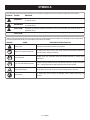 6
6
-
 7
7
-
 8
8
-
 9
9
-
 10
10
-
 11
11
-
 12
12
-
 13
13
-
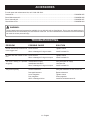 14
14
-
 15
15
-
 16
16
-
 17
17
-
 18
18
-
 19
19
-
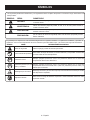 20
20
-
 21
21
-
 22
22
-
 23
23
-
 24
24
-
 25
25
-
 26
26
-
 27
27
-
 28
28
-
 29
29
-
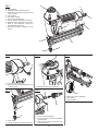 30
30
-
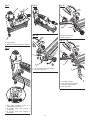 31
31
-
 32
32


Husky H100FS Manual de usuario
- Categoría
- Pistola de clavos
- Tipo
- Manual de usuario
- Este manual también es adecuado para
en otros idiomas
- English: Husky H100FS User manual
Artículos relacionados
Otros documentos
-
RIDGID R150FSF Manual de usuario
-
Ryobi YG125CS Guía del usuario
-
-
-
-
RIDGID R692SBEN Guía del usuario
-
-
-
-
Ryobi P360 Guía del usuario