Craftsman CMXGBAM1054541 Manual de usuario
- Categoría
- Lanzadores de nieve
- Tipo
- Manual de usuario

CAUTION
Before using this equipment, read the manual and follow all safety rules and operating instructions.
CRAFTSMAN® is a registered trademark of Stanley Black & Decker, Inc., used under license.
CRAFTSMAN® es una marca registrada de Stanley Black & Decker, Inc., utilizada bajo licencia.
© 2018 CRAFTSMAN U.S. & Canada Only
CRAFTSMAN.com
Form No. 769-15670
(June 4, 2018)
INSTRUCTION MANUAL | GUIDE D’UTILISATION
SNOW BLOWER
Model Nos. CMXGBAM1054541
CMXGBAM1054542
CMXGBAM1054543
CMXGBAM1054544
CMXGBAM1054546
IF YOU HAVE QUESTIONS OR COMMENTS, CONTACT US.
POUR TOUTE QUESTION OU TOUT COMMENTAIRE, NOUS CONTACTER.
1-888-331-4569 WWW.CRAFTSMAN.COM
NOTE: This Operator’s Manual covers several models. Features may vary by model. Not all features in this manual are applicable to all models and the model depicted may differ
from yours. The terms “snow thrower” and “snow blower” may be used interchangeably for this product.

2
TABLE OF CONTENTS
© Sears Brands, LLC
MODEL NUMBERPRODUCT SPECIFICATIONS
Engine Oil: 5W-30
Fuel: Unleaded Gasoline
Spark Plug: F6RTC (Sears Part #951-10292)
Spark Plug Gap: .020” to 0.030”
Model Number ________________________________
Serial Number _________________________________
Date of Purchase _______________________________
Record the model number, serial number,
and date of purchase above.
Safe Operation Practices .........................Page 3
Assembly ........................................Page 7
Operation ......................................Page 21
Service &Maintenance .......................... Page 28
Off-Season Storage ............................. Page 36
Troubleshooting ............................... Page 37
Warranty Statement ...........See Separate Supplement
Español ........................................ Page 39

3
SAFETY INSTRUCTIONS
NOTE: The terms “snow thrower” and “snow blower” may be used interchangeably
for this product.
TRAINING
• Read, understand, and follow all instructions on the machine and in the
manual(s) before attempting to assemble and operate. Failure to do so can
result in serious injury to the operator and/or bystanders. Keep this manual
in a safe place for future and regular reference and for ordering replacement
parts.
• Be familiar with all controls and their proper operation. Know how to stop
the machine and disengage them quickly.
• Never allow children under 14 years of age to operate this machine. Children
14 and over should read and understand the instructions and safe operation
practices in this manual and on the machine and be trained and supervised
by an adult.
• Never allow adults to operate this machine without proper instruction.
• Thrown objects can cause serious personal injury. Plan your snow-throwing
pattern to avoid discharge of material toward roads, bystanders and the like.
• Keep bystanders, pets and children at least 75 feet from the machine while it
is in operation. Stop machine if anyone enters the area.
• Exercise caution to avoid slipping or falling, especially when operating in
reverse.
PREPARATION
• Thoroughly inspect the area where the equipment is to be used. Remove all
doormats, newspapers, sleds, boards, wires and other foreign objects, which
could be tripped over or thrown by the auger/impeller.
• Always wear safety glasses or eye shields during operation and while
performing an adjustment or repair to protect your eyes. Thrown objects
which ricochet can cause serious injury to the eyes.
• Do not operate without wearing adequate winter outer garments. Do not
wear jewelry, long scarves or other loose clothing, which could become
entangled in moving parts. Wear footwear which will improve footing on
slippery surfaces.
• Use a grounded three-wire extension cord and receptacle for all machines
with electric start engines.
• Disengage all control levers before starting the engine.
• Adjust collector housing height to clear gravel or crushed rock surfaces.
• Never attempt to make any adjustments while engine is running, except
where specifically recommended in the operator’s manual.
• Let engine and machine adjust to outdoor temperature before starting to
clear snow.
Safe Handling of Gasoline:
To avoid personal injury or property damage use extreme care in handling
gasoline. Gasoline is extremely flammable and the vapors are explosive.
Serious personal injury can occur when gasoline is spilled on yourself or your
clothes which can ignite. Wash your skin and change clothes immediately.
• Use only an approved gasoline container.
• Never fill containers inside a vehicle or on a truck or trailer bed with a plastic
liner. Always place containers on the ground away from your vehicle before
filling.
• When practical, remove gas-powered equipment from the truck or
trailer and refuel it on the ground. If this is not possible, then refuel such
equipment on a trailer with a portable container, rather than from a gasoline
dispenser nozzle.
• Keep the nozzle in contact with the rim of the fuel tank or container opening
at all times until fueling is complete. Do not use a nozzle lock-open device.
• Extinguish all cigarettes, cigars, pipes and other sources of ignition.
• Never fuel machine indoors.
• Never remove gas cap or add fuel while the engine is hot or running. Allow
engine to cool at least two minutes before refueling.
• Never over fill fuel tank. Fill tank to no more than ½ inch below bottom of
filler neck to allow space for fuel expansion.
• Replace gasoline cap and tighten securely.
WARNING
This symbol points out important safety instructions which, if not
followed, could endanger the personal safety and/or property of
yourself and others. Read and follow all instructions in this manual
before attempting to operate this machine. Failure to comply with these
instructions may result in personal injury. When you see this symbol, HEED
ITS WARNING!
WARNING
CALIFORNIA PROPOSITION 65
Engine Exhaust, some of its constituents, and certain vehicle components
contain or emit chemicals known to State of California to cause cancer and
birth defects or other reproductive harm.
DANGER
This machine was built to be operated according to the safe operation
practices in this manual. As with any type of power equipment,
carelessness or error on the part of the operator can result in serious injury.
This machine is capable of amputating fingers, hands, toes and feet and
throwing debris. Failure to observe the following safety instructions could
result in serious injury or death.
WARNING
Your Responsibility—Restrict the use of this power machine to
persons who read, understand and follow the warnings and instructions in
this manual and on the machine.
SAVE THESE INSTRUCTIONS!

4
SAFETY INSTRUCTIONS
• If gasoline is spilled, wipe it off the engine and equipment. Move unit to
another area. Wait 5 minutes before starting the engine. If fuel is spilled on
clothing, change clothing immediately.
• To reduce fire hazards, keep machine free of grass, leaves, or other debris
build-up. Clean up oil or fuel spillage and remove any fuel soaked debris.
• Never store the machine or fuel container inside where there is an open
flame, spark or pilot light as on a water heater, space heater, furnace, clothes
dryer or other gas appliances.
OPERATION
• Do not put hands or feet near rotating parts, in the auger/impeller housing
or chute assembly. Contact with the rotating parts can amputate hands and
feet.
• The auger/impeller control lever is a safety device. Never bypass its
operation. Doing so makes the machine unsafe and may cause personal
injury.
• The control levers must operate easily in both directions and automatically
return to the disengaged position when released.
• Never operate with a missing or damaged chute assembly. Keep all safety
devices in place and working.
• Never run an engine indoors or in a poorly ventilated area. Engine exhaust
contains carbon monoxide, an odorless and deadly gas.
• Do not operate machine while under the influence of alcohol or drugs.
• Muffler and engine become hot and can cause a burn. Do not touch. Keep
children away.
• Exercise extreme caution when operating on or crossing gravel surfaces. Stay
alert for hidden hazards or traffic.
• Exercise caution when changing direction and while operating on slopes. Do
not operate on steep slopes.
• Plan your snow-throwing pattern to avoid discharge towards windows,
walls, cars etc. Thus, avoiding possible property damage or personal injury
caused by a ricochet.
• Never direct discharge at children, bystanders and pets or allow anyone in
front of the machine.
• Do not overload machine capacity by attempting to clear snow at too fast of
a rate.
• Never operate this machine without good visibility or light. Always be sure of
your footing and keep a firm hold on the handles. Walk, never run.
• Disengage power to the auger/impeller when transporting or not in use.
• Never operate machine at high transport speeds on slippery surfaces. Look
down and behind and use care when backing up.
• After striking a foreign object or if the machine should start to vibrate
abnormally, stop the engine, disconnect the spark plug wire and ground
it against the engine. Inspect thoroughly for damage. Repair any damage
before starting and operating.
• Disengage all control levers and stop engine before you leave the operating
position (behind the handles). Wait until the auger/impeller comes to
a complete stop before unclogging the chute assembly, making any
adjustments, or inspections.
• Never put your hand in the discharge or collector openings. Do not unclog
chute assembly while engine is running. Shut off engine and remain behind
handles until all moving parts have stopped before unclogging.
• Use only attachments and accessories approved by the manufacturer (e.g.
wheel weights, tire chains, cabs etc.).
• When starting engine, pull cord slowly until resistance is felt, then pull
rapidly. Rapid retraction of starter cord (kickback) will pull hand and arm
toward engine faster than you can let go. Broken bones, fractures, bruises or
sprains could result.
• If situations occur which are not covered in this manual, use care and good
judgment.
CLEARING A CLOGGED DISCHARGE CHUTE
Hand contact with the rotating impeller inside the discharge chute is the most
common cause of injury associated with snow throwers. Never use your hand to
clean out the discharge chute.
To clear the chute:
a. SHUT THE ENGINE OFF!
b. Wait 10 seconds to be sure the impeller blades have stopped
rotating.
c. Always use a clean-out tool, not your hands.
MAINTENANCE & STORAGE
• Never tamper with safety devices. Check their proper operation regularly.
Refer to the maintenance and adjustment sections of this manual.
• Before cleaning, repairing, or inspecting machine disengage all control
levers and stop the engine. Wait until the auger/impeller come to a complete
stop. Disconnect the spark plug wire and ground against the engine to
prevent unintended starting.
• Check bolts and screws for proper tightness at frequent intervals to keep the
machine in safe working condition. Also, visually inspect machine for any
damage.
• Do not change the engine governor setting or over-speed the engine. The
governor controls the maximum safe operating speed of the engine.
• Snow thrower shave plates and skid shoes are subject to wear and damage.
For your safety protection, frequently check all components and replace
with original equipment manufacturer’s (OEM) parts only as listed in the
Parts pages of this operator’s manual. Use of parts which do not meet the
original equipment specifications may lead to improper performance and
compromise safety!
• Check control levers periodically to verify they engage and disengage
properly and adjust, if necessary. Refer to the adjustment section in this
operator’s manual for instructions.
• Maintain or replace safety and instruction labels, as necessary.

5
SAFETY INSTRUCTIONS
• Observe proper disposal laws and regulations for gas, oil, etc. to protect the
environment.
• Prior to storing, run machine a few minutes to clear snow from machine and
prevent freeze up of auger/impeller.
• Never store the machine or fuel container inside where there is an open
flame, spark or pilot light such as a water heater, furnace, clothes dryer etc.
• Always refer to the operator’s manual for proper instructions on off-season
storage.
• Check fuel line, tank, cap, and fittings frequently for cracks or leaks. Replace
if necessary.
• Do not crank engine with spark plug removed.
• According to the Consumer Products Safety Commission (CPSC) and the
U.S. Environmental Protection Agency (EPA), this product has an Average
Useful Life of seven (7) years, or 60 hours of operation. At the end of
the Average Useful Life have the machine inspected annually by an
authorized service dealer to ensure that all mechanical and safety systems
are working properly and not worn excessively. Failure to do so can result in
accidents, injuries or death.
DO NOT MODIFY ENGINE
To avoid serious injury or death, do not modify engine in any way. Tampering
with the governor setting can lead to a runaway engine and cause it to
operate at unsafe speeds. Never tamper with factory setting of engine
governor.
NOTICE REGARDING EMISSIONS
Engines which are certified to comply with California and federal EPA
emission regulations for SORE (Small Off Road Equipment) are certified
to operate on regular unleaded gasoline, and may include the following
emission control systems: Engine Modification (EM), Oxidizing Catalyst (OC),
Secondary Air Injection (SAI) and Three Way Catalyst (TWC) if so equipped.

6
SAFETY INSTRUCTIONS
SAFETY SYMBOLS
This page depicts and describes safety symbols that may appear on this product. Read, understand, and follow all instructions on the machine before
attempting to assemble and operate.
Symbol Description
READ THE OPERATOR’S MANUAL(S)
Read, understand, and follow all instructions in the manual(s) before attempting to assemble and
operate.
WARNING— ROTATING BLADES
Keep hands out of inlet and discharge openings while machine is running. There are rotating blades
inside.
WARNING— ROTATING BLADES
Keep hands out of inlet and discharge openings while machine is running. There are rotating blades
inside.
WARNING— ROTATING AUGER
Do not put hands or feet near rotating parts, in the auger/impeller housing or chute assembly.
Contact with the rotating parts can amputate hands and feet.
WARNING—THROWN OBJECTS
This machine may pick up and throw and objects which can cause serious personal injury.
WARNING—GASOLINE IS FLAMMABLE
Allow the engine to cool at least two minutes before refueling.
WARNING— CARBON MONOXIDE
Never run an engine indoors or in a poorly ventilated area. Engine exhaust contains carbon
monoxide, an odorless and deadly gas.
WARNING— ELECTRICAL SHOCK
Do not use the engine’s electric starter in the rain.
WARNING— HOT SURFACE
Engine parts, especially the muffler, become extremely hot during operation. Allow engine and
muffler to cool before touching.
WARNING: Your Responsibility—Restrict the use of this power machine to persons who read, understand and follow
the warnings and instructions in this manual and on the machine.
SAVE THESE INSTRUCTIONS!

7
ASSEMBLY
NOTE: This Operator’s Manual covers several models. Features may vary by model. Not all features in this manual are applicable to all models and the model depicted may
differ from yours. Refer to Figure 1 which shows the different versions and match the contents of carton (chute and directional control rod/flex shaft) to identify your
specific unit.
Electric Chute Control
Page 16
Manual Chute
Control Rod
Chute
Assembly
Flex Shaft
Overhead Chute Control
(w/ Flex Shaft Steel Chute)
Page 14
Chute Assembly
Standard Side Crank Chute Control
Page 10
Standard Side Crank Rod
Assembly
Chute
Assembly
Overhead Chute Control
(w/ Chute Control Rod)
Page 11
Overhead Chute
Control Rod
Chute
Assembly
2-Way & 4-Way Chute Control
Page 12
Chute Control Rod
Chute
Assembly
Figure 1

8
ASSEMBLY
NOTE: References to right or left side of the snow blower are determined from
behind the unit in the operating position (standing directly behind the snow
blower, facing the handle panel).
UNPACKING: Removing From Carton
1. Cut the corners of the carton and lay the sides flat on the ground. Remove
and discard all packing inserts.
2. Move the snow blower out of the carton.
3. Make certain the carton has been completely emptied before discarding it.
Handle Assembly
Refer to Figure 1 and proceed to your applicable chute style.
1. Cut cable ties securing chute control rod or upper handle to the lower handle
(if applicable), set aside the chute control rod (if applicable) and remove the
wrap around the handles (if applicable).
NOTE: Do not cut the cable tie securing the cables to the engine for units equipped.
NOTE: On units with Overhead Chute Control, Four-Way Chute Control, and Electric
Chute Control cut cable ties securing flex shaft to the lower handle and set the flex
shaft aside. Remove rubber bands securing cables to carriage screws and cut cable
tie securing shift rod to lower handle. Refer to Figure to help identify your unit.
2. Observe the lower rear area of the snow blower to be sure both cables are
aligned with roller guides before pivoting the handle upward. See Figure 2.
Figure 2
3. Loosen the top two lock nuts securing the upper and lower handle and
remove the two carriage screws from the lower handle and set aside. See
Figure 3 or Figure 4 for units with side supports.
Figure 3
Figure 4

9
ASSEMBLY
4. Place shift lever in Forward-6 position or fastest forward speed (if equipped).
5. Pull up and back on upper handle as shown in Figure 5. As you are raising the
handle upward, make sure that both ends of the center cable are positioned
properly in the brackets. Align upper handle with the lower handle.
NOTE: On select units with steel rod speed selectors, you may need to lower shift
rod to the side slightly to maneuver handle panel over it when pivoting handle
upward.
Figure 5
6. Attach the two carriage screws and lock nuts removed in Step 2. Finish
securing the handle by tightening the top two lock nuts loosened in Step 2.
See Figure 6 or Figure 7 for units with side supports.
Figure 6
Figure 7
7. Remove and discard any rubber bands, if present. They are for packaging
purposes only.
8. On units equipped with cable guides on top of the engine, check that all
cables are properly routed through the cable guide. Then pull the cables
towards the chute and pull the cable tie on the engine snug on the cables to
secure in place.
NOTE: For smoothest operation, cables should all be to the left of the chute
directional control rod.
STOP
Refer to Figure 1 to identify your applicable chute style and continue to
Chute Assembly Options (page 9).
Chute Assembly Options
Refer to Figure 1 and proceed to your applicable Chute Control Style on pages 10-17.

10
ASSEMBLY
2. Close flange keepers to secure chute assembly to chute base. Flange keepers
will click into place when properly secure. See “Figure 10”10.
Figure 10
NOTE: Ensure the lower chute is secured to the flange on the chute base. The lower
edge of the chute keeper should be positioned below the flange on the chute base
after being clicked into place. If flange keepers will not easily click into place, use
palm of your hand to apply swift, firm pressure to the back of each.
Chute Directional Control Assembly
1. Remove plastic cap (if present), flat washer and hairpin clip from end of
chute directional control assembly. See Figure 11.
Figure 11
2. Insert end of chute directional control assembly into lower bracket and
secure chute directional control assembly with flat washer and hairpin clip
removed in Step 1. If necessary, lower bracket can be adjusted. Refer to
Chute Bracket Adjustment in Service section on page 32.
STOP
Continue to Set-Up (page 18).
Standard Side Crank Chute Control
Figure 8
1. Position chute assembly over base. See Figure 9.
Figure 9

11
ASSEMBLY
Overhead Chute Control (w/ Chute Control Rod)
Figure 12
1. Remove wing nut and hex screw from chute control head and clevis pin and
cotter pin from chute support bracket. Position chute assembly (forward-
facing) over chute base. See Figure 13.
Chute Support Bracket
Chute Control Head
Chute
Chute Base
Figure 13
2. Place chute assembly onto chute base and secure chute control head to chute
support bracket with clevis pin and cotter pin removed in Step 1. See Figure
14.
Figure 14
3. Finish securing chute control head to chute support bracket with wing
nut (a) and hex screw (b) removed in Step 1. See Figure 15.
Figure 15

12
ASSEMBLY
4. Insert chute control rod into the support bracket on rear of the dash panel.
See Figure 16.
Figure 16
5. Remove hairpin clip (a) from rear of chute control head. See Figure 17.
Figure 17
6. Insert chute control rod (b) into rear of chute control head. See Figure 17.
Secure chute control rod to chute control assembly with hairpin clip removed
in Step 5.
STOP
Continue to Set-Up (page 18).
2-Way & 4-Way Chute Control
Figure 18
1. Remove hairpin clip, wing nut and hex screw from chute control head and
clevis pin and bow-tie cotter pin from chute support bracket. See Figure 19
Chute Control Head
Chute
Chute Support
Bracket
Chute Base
Figure 19

13
ASSEMBLY
NOTE: For smoothest operation, cables should all be to the left of the chute
directional control rod.
2. Insert chute control rod into chute control head. Push rod as far into chute
control head as possible, keeping holes in rod pointing upward. See
Figure 20.
Figure 20
3. Place chute onto chute base and ensure chute control rod is positioned under
handle panel. Install hex screw removed in Step 1, but do not secure with
wing nut at this time. Figure 21.
Figure 21
4. Squeeze trigger on joystick and rotate chute by hand to face forward. The
holes in chute control input will be facing up. See Figure 22.
Chute Control Input
Top View
Joystick
Figure 22
NOTE: Chute will not rotate without squeezing trigger on joystick.
5. Rotate joystick to one o’clock position so that indicator arrow on pinion gear
below control panel faces upward. See Figure 23.
Figure 23
6. Insert chute control rod into pinion gear below joystick. Make sure to line up
hole in rod with arrow on pinion gear. See Figure 24.

14
ASSEMBLY
Figure 24
NOTE: Chute control rod will fit snug into pinion gear. Support rear of dash
panel with one hand while inserting rod with your other hand to ensure rod
is inserted all the way into pinion gear.
NOTE: The hole in the chute directional control rod is a reference for aligning
rod with indicator arrow on pinion gear, and will be visible after rod has been
inserted.
7. Push chute control rod toward control panel until hole in rod lines up with
hole in chute control input closest to chute control head and insert hairpin
clip (a)removed in Step 1. See Figure 25.
Figure 25
NOTE: Second hole is used to achieve further engagement of chute control
rod into pinion gear if required. Refer to Service section for Chute Control
Rod adjustments.
8. Finish securing chute control head to chute support bracket with wing nut,
clevis pin, and bow-tie cotter pin (e) removed in Step 1.
STOP
Continue to Set-Up (page 18).
Overhead Chute Control (w/ Flex Shaft & Steel Chute)
Figure 26
1. Remove lock nuts and hex screws from chute support bracket (this will
require two wrenches). See Figure 27.
2. Place chute assembly onto chute base and chute control head onto chute
support bracket. See Figure 27.
Chute
Assembly
Chute Base
Chute
Support
Bracket
Chute Control
Head
Figure 27

15
ASSEMBLY
3. Secure chute control head to chute support bracket with lock nuts and hex
screws removed in Step 1. See Figure 28.
Figure 28
NOTE: For smoothest operation, the cables should all be to the left of the chute
control rod.
4. Remove hairpin clip from rear of chute control assembly. See Figure 29.
Figure 29
5. Insert flex shaft removed during handle assembly from lower handle into
rear of chute directional control head. See Figure 29. Secure flex shaft to
chute control head with hairpin clip removed in Step 4.
6. Insert hex end of flex shaft into chute control rod coupling under dash panel.
See Figure 30.
Figure 30
7. Ensure speed selector is in fastest forward speed.
8. Remove cotter pin and washer from ferrule on end of shift rod. See “Figure
31” inset.
Figure 31

16
ASSEMBLY
9. Make sure the shift lever on the back of the transmission is rotated
downward to the full extent of its rotation. See Figure 32.
Figure 32
10. Insert ferrule into top hole of shift lever and secure with cotter pin (a) and
washer (b) removed in Step 8. See Figure 31. Ferrule may need to be adjusted
up or down.
STOP
Continue to Set-Up (page 18).
Electric Chute Control
Figure 33
1. Remove cotter pin, wing nut, and hex screw from chute control head and
clevis pin and bow-tie cotter pin from chute support bracket. See Figure 34.
Chute Control Head
Chute
1
1
2
Chute
Support
Bracket
Chute Base
Figure 34
NOTE: For smoothest operation, the cables should all be to the left of the chute
control rod.

17
ASSEMBLY
2. Insert the round end of the chute control rod into input of chute control
head. Push rod as far into the chute control head as possible, keeping the
holes in the rod pointing upward. See Figure 35.
Figure 35
3. Place chute onto chute base and ensure chute control rod is positioned under
handle panel. Secure chute control head to chute support bracket with clevis
pin and bow-tie cotter pin removed in Step 1. See Figure 36.
Figure 36
4. Finish securing chute control head by installing hex screw and wing nut
removed in Step 2. See Figure 37.
Figure 37
5. Insert the other end of the chute control rod into the input shaft below the
handle panel. Make sure to line up the flat end of the rod and the flat end
of the input shaft. You may need to rotate the rod around until these two
surfaces line up. See Figure 38.
Figure 38

18
ASSEMBLY
6. Push the chute control rod toward the control panel until the hole in the rod
lines up with the middle hole in the chute control input and insert the cotter
pin removed in Step 1. See Figure 39.
Figure 39
NOTE: There is a reference hole provided at rear end of control rod to help
know when holes are vertical.
NOTE: The hole furthest from the chute control head is used to achieve
further engagement of the chute control rod into the input shaft if required.
Refer to Page 33 of the Maintenance & Adjustments section for Chute Control
Rod adjustment.
The hole closest to the chute control head is used for manual movement of
the chute assembly if required. Refer to page 24 of the Operation section.
STOP
Continue to Set-Up (page 18).
Set-Up
Chute Control Cable Routing (If Equipped)
For units equipped with 2-way or 4-way chute control joystick, electric chute
control and/or chute-pitch controls, ensure control cables are routed properly.
NOTE: For smoothest operation, cables should all be to the left of the chute
directional control rod.
NOTE: The number of cables routed through the wire guides will depend on unit
model.
1. Locate cable guide on top of engine and ensure cable(s) are properly routed
through the cable guide. See Figure 40.
Figure 40
Shear Pins
Holes are located in the plastic dash panel for convenient shear pin storage. See
Figure 41. Refer to page 16 28 in the Operation section for more information
regarding shear pin replacement.
NOTE: If the extra shear pins are not already assembled in the handle panel, they
can be found in the manual bag.
Figure 41

19
ASSEMBLY
Chute Clean-Out Tool
A chute clean-out tool is fastened to the top of the auger housing with a mounting
clip. See Figure 42. The tool is designed to clear a chute assembly of ice and
snow. This item is fastened with a cable tie at the factory. Cut the cable tie before
operating the snow blower.
WARNING
Never use your hands to clear a clogged chute assembly. Shut OFF engine
and remain behind handles until all moving parts have stopped before
using the clean-out tool to clear the chute assembly.
Chute Clean-Out Tool
Figure 42
Drift Cutters (if equipped)
1. Remove the two screws and wing knobs that secure each drift cutter, and
remove them from the sides of the auger housing.
2. Turn the drift cutters around and position them as shown in Figure 43 to the
outside of the auger housing.
Figure 43
3. Attach the drift cutters with the screws and wing knobs on the outside of the
auger housing as shown in Figure 44.
Figure 44
Tire Pressure (If Applicable)
WARNING
Under any circumstance do not exceed manufacturer’s recommended psi.
Equal tire pressure should be maintained at all times. Excessive pressure
when seating beads may cause tire/rim assembly to burst with force
sufficient to cause serious injury. Refer to sidewall of tire for recommended
pressure.
The tires are over-inflated for shipping purposes. Check the tire pressure before
operating the snow blower. Refer to the tire side wall for tire manufacturer’s
recommended psi and deflate (or inflate) the tires as necessary.
NOTE: Equal tire pressure is to be maintained at all times for performance purposes.
Adjustments
Skid Shoes
The snow blower skid shoes are adjusted at the factory to be approx 1/8” below
the bottom surface of the shave plate. Adjust them downward, if desired, prior to
operating the snow blower.
CAUTION
It is not recommended that you operate this snow blower on gravel as
it can easily pick up and throw loose gravel, causing personal injury or
damage to the snow blower and surrounding property.
• For close snow removal on a smooth surface, raise skid shoes higher on the
auger housing. Refer to Figure 45.
• Use a middle or lower position when the area to be cleared is uneven, such as
a gravel driveway.
NOTE: If you choose to operate the snow blower on a gravel surface, keep the
skid shoes in position for maximum clearance between the ground and the
shave plate.

20
ASSEMBLY
To adjust the skid shoes:
1. Loosen the four hex nuts (two on each side), flat washers, and carriage bolts.
Move skid shoes to desired position. See Figure 45.
2. Make certain the entire bottom surface of skid shoe is against the ground to
avoid uneven wear on the skid shoes.
3. Retighten nuts, washers, and bolts securely.
Smooth Surface
Uneven Surface
Figure 45
NOTE: The skid shoes on your unit may look slightly different (and have different
hardware) than ones shown in Figure 45.
Auger Control
WARNING
Prior to operating your snow blower, carefully read and follow all
instructions below. Perform all adjustments to verify your snow blower is
operating safely and properly.
Check the adjustment of the auger control as follows:
1. The auger control is located on the left handle. See Figure 46 inset. When
the auger control is released and in the disengaged “UP” position, the cable
should have very little slack. It should NOT be tight.
2. In a well-ventilated area, start the snow blower engine as instructed in
Starting Engine on page 25-26 in the Operation section of this manual.
3. While standing in the operator’s position (behind the snow blower), engage
the auger.
4. Allow the auger to remain engaged for approximately ten seconds before
releasing the auger control. Repeat this several times.
5. With the auger control in the disengaged “UP” position, walk to the front of
the machine.
6. Confirm that the auger has completely stopped rotating and shows NO signs
of motion. If the auger shows ANY signs of rotating, immediately return to
the operator’s position and shut OFF the engine. Wait for ALL moving parts
to stop before adjusting the auger control.
Auger Control
Figure 46
7. To readjust the control cable, loosen the upper hex bolt on the auger cable
bracket. See Figure 46.
8. Position the bracket upward to provide more slack (or downward to increase
cable tension).
9. Retighten the upper hex bolt.
10. Repeat Step 2 through Step 6 above to verify proper adjustment has been
achieved.

21
OPERATION
Meets ANSI Safety Standards
Craftsman Snow Blowers conform to the safety standard of the American National Standards Institute (ANSI).
† If Equipped
Standard
Chute
Directional
Control †
Shift Lever
Augers
Skid Shoe
Clean Out
Tool
Chute Assembly
Drive Control Lever
Auger Control Lever
Auger Housing
LED Light Bar †
Drift Cutters †
Overhead
Chute
Directional
Control †
Heated
Grips
†
Shift Lever
4-Way/2-Way
Chute
Directional
Control
Joystick
†
Shift Rod
Manual Chute
Directional
Control
†
Electric Chute
Directional
Control
Joystick
†
Steering
Trigger
Control
†
Shift
Lever
Shift Lever
Muffler
Muffler
Choke
Control
Choke Control
Safety Key
Safety Key
Throttle
Control
Throttle
Control
Recoil Starter
Handle
Recoil Starter
Handle
Oil Drain
Oil Drain
Fuel Cap
Fuel Cap
Oil Fill
Oil Fill
Electric Starter
Outlet/Switchbox
Primer
Primer
Electric Starter
Button
Electric
Starter
Button
Electric Starter Outlet
Figure 47

22
OPERATION
Now that you have set up your snow blower, it’s important to become acquainted
with its controls and features. Refer to Figure 47.
NOTE: This Operator’s Manual covers several models. Snow blower features may
vary by model. Not all features in this manual are applicable to all snow blower
models and the snow blower depicted may differ from yours.
NOTE: All references to the left or right side of the snow blower are from the
operator’s position. Any exceptions will be noted.
Shift Lever
The shift lever is located on the right side of the handle panel. Place the shift lever
into any of eight positions to control the direction of travel and ground speed.
Forward
Your snow blower has six forward (F) speeds. Position one (1) is the slowest and
position six (6) is the fastest.
Reverse
Your snow blower has two reverse (R) speeds. Position one (1) is the slower and
position two (2) is the faster.
Drift Cutters (If Equipped)
The drift cutters are designed for use in deep snow. Their use is optional for normal
snow conditions. Maneuver the snow blower so that the cutters penetrate a high
standing snow drift to assist snow falling into the augers for throwing.
Safety Key
The safety key is a safety device. It must be fully inserted in
order for the engine to start. Remove the safety key when
the snow blower is not in use.
NOTE: Do not turn the safety key in an attempt to start the
engine. Doing so may cause it to break.
Choke Control
The choke control is found on the rear of the engine and is
activated by turning the rotary choke knob to the CHOKE
position. Activating the choke control closes the choke
plate on the carburetor and aids in starting the engine.
Recoil Starter Handle
This handle is used to manually start the engine.
LED Light (If Equipped)
The LED light is located inside of the handle panel and is ON when the engine is
running.
LED Light Bar (If Equipped)
The LED headlight is located on top of the auger housing and is automatically
turned ON when the engine is started.
Throttle Control
The throttle control is located on the rear of the engine. It regulates the speed of the
engine and will shut off the engine when moved into the STOP position.
Primer
Depressing the primer forces fuel directly into the
engine’s carburetor to aid in cold-weather starting.
Electric Starter Button (If Equipped)
Pressing the electric starter button engages the engine’s electric starter when
plugged into a 120V power source.
Electric Starter Outlet (If Equipped)
Requires the use of a three-prong outdoor extension cord and a 120V power source/
wall outlet.
Oil Fill
Engine oil level can be checked and oil added through the oil fill.
Fuel Cap
Unthread the fuel cap to add gasoline to the fuel tank.
Auger
When engaged, the auger blades rotate and draw snow into the auger housing.
Chute Assembly
Snow drawn into the auger housing is discharged out the chute assembly.
Skid Shoes
Position the skid shoes based on surface conditions. Adjust upward for hard-packed
snow. Adjust downward when operating on gravel or crushed rock surfaces.
Wheel Steering Controls (If Equipped)
The left and right wheel steering controls are located on the underside of the
handles. Squeeze the right control to turn right; squeeze the left control to turn left.
NOTE: Operate the snow blower in open areas until you are familiar with these
controls.

23
OPERATION
Auger Control
AUGER
CONTROL
GO
The auger control is located on the left handle. Squeeze the control grip against the
handle to engage the auger and start snow throwing action. Release to stop.
IMPORTANT: Refer to the Auger Control information in the Assembly & Set-Up section
prior to operating your snow blower. Read and follow all instructions carefully and
perform all adjustments to verify your snow blower is operating safely and properly.
Drive Control/ Auger Control Lock*
DRIVE
CONTROL
GO
The drive control is located on the right handle. Squeeze the control grip against the
handle to engage the wheel drive. Release to stop.
*On select models, the drive control also locks the auger control so you can operate
the chute directional control without interrupting the snow throwing process. If the
auger control is engaged simultaneously with the drive control, the operator can
release the auger control (on the left handle) and the augers will remain engaged.
Release both controls to stop the augers and wheel drive.
NOTE: Always release the drive control before changing speeds. Failure to do so will
result in increased wear on your machine’s drive system.
Overhead Chute Directional Control (If Equipped)
CHUTE DIRECTIONAL CONTROL
DISCHARGE
LEFT
DISCHARGE
RIGHT
ADJUSTABLE
CHUTE TILT
The overhead chute directional control is located in the center of the snow blower
between the handle panel and lower handle. To change the direction in which snow
is thrown, rotate the chute directional control.
Two-Way Chute Control (If Equipped)
The two-way chute control (Joystick) is located on the left side of the handle panel.
• To change the direction in which snow is thrown, squeeze the button on the
chute control lever and pivot the chute control lever to the right or to the
left.

24
OPERATION
Four-Way Chute Control (Joystick) (If Equipped)
The four-way chute control™ (joystick) is located on the left side of the handle
panel.
• To change the direction in which snow is thrown, squeeze the button on the
chute control lever and pivot the chute control lever to the right or to the
left.
• To change the angle/distance which snow is thrown, pivot the chute control
lever forward to tilt the chute down and backward to tilt the chute up.
Electric Chute Control Joystick (If Equipped)
DIRECTIONAL CONTROL
ELECTRIC CHUTE
CHUTE
ROTATE
LEFT
CHUTE
ROTATE
RIGHT
CHUTE TILT UP
CHUTE TILT DOWN
The electric chute control (joystick) is located on the right side of the handle panel.
• To change the direction in which snow is thrown, move the joystick to the
right or to the left.
• To change the angle/distance which snow is thrown, pivot the joystick
forward to tilt the chute down and backward to tilt the chute up.
Manual Chute Control (Units with Electric Chute
Directional Control Joystick)
Follow this procedure to manually change the chute direction on units equipped
with an electric chute directional control joystick and manual chute directional
control rod only. See Figure 47.
1. Remove the cotter pin from either of the holes furthest from the chute
assembly on the chute control head.
2. Push in the chute control rod until the hole in it lines up with the third hole
in the chute control head. See Figure 48.
Figure 48
3. Reinsert the cotter pin through this hole and the chute control rod as shown
in Figure 48.
4. Grasp the indented portion of the chute control rod and manually rotate the
chute to the right or to the left. See Figure 49.
Figure 49

25
OPERATION
Clean-Out Tool
WARNING
Never use your hands to clear a clogged chute assembly. Shut off engine
and remain behind handles until all moving parts have stopped before
using the clean-out tool to clear the chute assembly.
The chute clean-out tool is conveniently fastened to the rear of the auger housing
with a mounting clip. Should snow and ice become lodged in the chute assembly
during operation, proceed as follows to safely clean the chute assembly and chute
opening:
1. Release both the Auger Control and the Drive Control.
2. Stop the engine by removing the ignition key.
3. Remove the clean-out tool from the clip which secures it to the rear of the
auger housing.
4. Use the shovel-shaped end of the clean-out tool to dislodge and scoop any
snow and ice which has formed in and near the chute assembly.
5. Refasten the clean-out tool to the mounting clip on the rear of the auger
housing, reinsert the ignition key and start the snow blower’s engine.
6. While standing in the operator’s position (behind the snow blower), engage
the auger control for a few seconds to clear any remaining snow and ice from
the chute assembly.
Before Starting Engine
WARNING
Read, understand, and follow all instructions and warnings on the
machine and in this manual before operating.
Oil
The unit was shipped with oil in the engine. Check oil level before each operation to
ensure adequate oil in the engine.
NOTE: Be sure to check the engine on a level surface with the engine stopped.
1. Remove the oil filler cap/dipstick and wipe the dipstick clean.
2. Insert the cap/dipstick into the oil filler neck, but do NOT screw it in.
3. Remove the oil filler cap/dipstick. If the level is low, slowly add oil (5W-30,
with a minimum classification of SF/SG) until oil level registers between high
(H) and low (L).
NOTE: Do not overfill. Overfilling with oil may result in engine smoking, hard
starting or spark plug fouling.
4. Replace and tighten cap/dipstick firmly before starting engine.
Gasoline
Use automotive gasoline (unleaded or low leaded to minimize combustion chamber
deposits) with a minimum of 87 octane. Gasoline with up to 10% ethanol or 15%
MTBE (Methyl Tertiary Butyl Ether) can be used. Never use an oil/gasoline mixture
or dirty gasoline. Avoid getting dirt, dust, or water in the fuel tank. DO NOT use E85
gasoline.
• Refuel in a well-ventilated area with the engine stopped. Do not smoke or
allow flames or sparks in the area where the engine is refueled or where
gasoline is stored.
• Do not overfill the fuel tank. After refueling, make sure the tank cap is closed
properly and securely.
• Be careful not to spill fuel when refueling. Spilled fuel or fuel vapor may
ignite. If any fuel is spilled, make sure the area is dry before starting the
engine.
• Avoid repeated or prolonged contact with skin or breathing of vapor.
WARNING
Use extreme care when handling gasoline. Gasoline is extremely
flammable and the vapors are explosive. Never fuel the machine indoors or
while the engine is hot or running. Extinguish cigarettes, cigars, pipes and
other sources of ignition.
1. Clean around fuel fill before removing cap to fuel.
2. Fill tank until fuel reaches 1⁄2 inch below the bottom of the filler neck to
allow space for fuel expansion. Be careful not to overfill.
Starting The Engine
WARNING
Always keep hands and feet clear of moving parts. Do not use a pressurized
starting fluid. Vapors are flammable.
NOTE: Allow the engine to warm up for a few minutes after starting. The engine will
not develop full power until it reaches operating temperatures.
1. Make certain both the auger control and drive control are in the disengaged
(released) position.
2. Insert key into slot. Make sure it snaps into place. Do not attempt to turn the
key.
NOTE: The engine cannot start without the key fully inserted into the
ignition switch.

26
OPERATION
Electric Starter
WARNING
The electric starter is equipped with a grounded three-wire power plug,
and is designed to operate on 120 volt AC household current. It must be
used with a properly grounded three-prong receptacle at all times to avoid
the possibility of electric shock. Follow all instructions carefully prior to
operating the electric starter. DO NOT use electric starter in the rain.
Determine that your home’s wiring is a three-wire grounded system. Ask a licensed
electrician if you are not certain.
If you have a grounded three-prong receptacle, proceed as follows. If you do not
have the proper house wiring, DO NOT use the electric starter under any conditions.
1. Plug an extension cord into the outlet located on the engine’s surface. Plug
the other end of extension cord into a three-prong 120-volt, grounded, AC
outlet in a well-ventilated area.
CAUTION
The extension cord can be any length, but must be rated for 15 amps at
125 volts, grounded and rated for outdoor use.
2. Move throttle control to FAST (rabbit)
position.
3. Move choke to the CHOKE
position (cold engine start). If engine is
warm, place choke in RUN position.
4. Push primer three (3) times, making sure to cover vent hole in primer bulb
when pushing. If engine is warm, push primer only once. Always cover vent
hole when pushing. Cool weather may require priming to be repeated.
5. Push starter button to start engine. Once the engine starts, immediately
release starter button. Electric starter is equipped with thermal overload
protection; system will temporarily shut-down to allow starter to cool if
electric starter becomes overloaded.
6. As the engine warms, slowly rotate the choke control to RUN position. If the
engine falters, restart engine and run with choke at half-choke position for a
short period of time, and then slowly rotate the choke into RUN position.
7. After engine is running, disconnect extension cord from electric starter.
When disconnecting, always unplug the end at the wall outlet before
unplugging the opposite end from the engine.
Recoil Starter
CAUTION
Do not pull the starter handle while the engine running.
1. Move throttle control to FAST (rabbit)
position.
2. Move choke to the CHOKE
position (cold engine start). If engine is
warm, place choke in RUN position.
3. Push primer three (3) times, making sure to cover vent hole when pushing.
If engine is warm, push primer only once. Always cover vent hole when
pushing. Cool weather may require priming to be repeated.
4. Pull gently on the starter handle until it begins to resist, then pull quickly
and forcefully to overcome the compression. Do not release the handle and
allow it to snap back. Return rope SLOWLY to original position. If required,
repeat this step.
WARNING
Keep a firm grip on the starter cord handle to prevent rapid retraction of
starter cord (kickback). Rapid retraction can pull hand and arm toward
engine faster than you can let go, and result in broken bones, fractures,
bruises or sprains.
5. As the engine warms, slowly rotate the choke control to RUN position. If the
engine falters, restart engine and run with choke at half-choke position for a
short period of time, and then slowly rotate the choke into RUN position.
WARNING
To avoid unsupervised engine operation, never leave the machine
unattended with the engine running. Turn the engine off after use and
remove key.
Stopping The Engine
After you have finished snow-throwing, run engine for a few minutes before
stopping to help dry off any moisture on the engine.
1. Move throttle control to OFF position.
2. Remove the key. Removing the key will reduce the possibility of
unauthorized starting of the engine while equipment is not in use. Keep the
key in a safe place. The engine cannot start without the key.
3. Wipe any moisture away from the controls on the engine.
To Engage Drive
1. With the throttle control in the Fast (rabbit) position, move shift lever
into one of the six forward (F) positions or two reverse (R) positions. Select a
speed appropriate for the snow conditions and a pace you’re comfortable
with.
NOTE: When selecting a Drive Speed, use the slower speeds until you are
comfortable and familiar with the operation of the snow blower.
2. Squeeze the drive control against the handle and the snow blower will move.
Release it and drive motion will stop.
NOTE: NEVER reposition the shift lever (change speeds or direction of travel)
without first releasing the drive control and bringing the snow blower to a complete
stop. Doing so will result in premature wear to the snow blower’s drive system.
To Engage Auger
1. To engage the auger and start throwing snow, squeeze the auger control
against the left handle. Release to stop the auger.

27
OPERATION
Replacing Shear Pins
WARNING
NEVER replace the auger shear pins with anything other than OEM Part
No. 738-04124A (gold colored replacement shear pins) or OEM Part No.
738-05273 (Black colored replacement shear pins). Any damage to the
auger gearbox or other components as a result of failing to do so will NOT
be covered by your snow blower’s warranty.
WARNING
Always turn off the snow blower’s engine and remove the key prior to
replacing shear pins.
Each auger blade is secured to the spiral shaft with a shear pin and bow-tie clip. If
an auger blade strikes a foreign object or ice jam, the pin will shear off to prevent
damage to the blade. If an auger blade does not turn, check to see if its pin has
sheared off.
IMPORTANT: ALWAYS use the correct OEM replacement shear pin.
2-Stage Snow Blowers
• The auger is secured to the spiral shaft using gold colored shear pins (Sears
OEM Part No. 738-04124A). See Figure 50.
Figure 50
3-Stage Snow Blowers
• The side augers and central accelerator auger are secured to the spiral shaft
using black shear pins (OEM Part No. 738-05273). See Figure 51.
Figure 51
Using Snow Blower to Clear Snow
WARNING
Check the area to be cleared for foreign objects. Remove foreign objects,
if any.
1. Start the engine following starting instructions.
2. Allow the engine to warm up for a few minutes as the engine will not
develop full power until it reaches operating temperature.
3. Rotate the chute assembly to the desired direction, away from bystanders
and/or buildings.
4. Making certain no bystanders or obstacles are in front of the unit, squeeze
the auger control completely against the upper handle to fully engage the
auger.
5. While the auger control is engaged, squeeze the drive control completely
against the upper handle to engage the wheels. Do not “feather” the drive
control.
6. As the snow blower starts to move, maintain a firm hold on the handle, and
guide the snow blower along the path to be cleared.
7. Release the auger and drive controls to stop the snow throwing action and
forward motion.
NOTE: Your unit is equipped with a clutch in the transmission. If the wheels
stop turning while trying to discharge large volumes of snow, immediately
disengage the drive control and allow the rotating auger to discharge snow
from the housing. Reduce the clearing width and continue operation.
8. On each succeeding pass, readjust the chute assembly to the desired position
and slightly overlap the previously cleared path.

28
SERVICE AND MAINTENANCE
WARNING
Before performing any type of maintenance/service, disengage all controls
and stop the engine. Wait until all moving parts have come to a complete
stop. Disconnect spark plug wire and ground it against the engine to
prevent unintended starting.
Follow the maintenance schedule given below. This chart describes service
guidelines only. Use the Service Log column to keep track of completed
maintenance tasks. To locate the nearest Sears Service Center or to schedule service,
call the following toll free number:1-888-331-4569.
MAINTENANCE SCHEDULE
Interval Item Service Service Log
Each Use and every 5 hours 1. Engine oil level
2. Loose or missing hardware
3. Unit and engine.
1. Check
2. Tighten or replace
3. Clean
1st 5 hours 1. Engine oil 1. Change
Annually or 25 hours 1. Spark plug
2. Control linkages and pivots
3. Wheels
4. Gear shaft and Auger shaft
5. 4-Way Chute Control
1. Check
2. Lube with light oil
3. Lube with multipurpose auto grease
4. Lube with light oil
5. Check for cable slackness
Annually or 50 hours 1. Engine oil 1. Change
Annually or 100 hours 1. Spark plug 1. Change
Before Storage 1. Fuel system 1. Run engine until it stops from lack of fuel
Engine Maintenance
Checking Engine Oil
WARNING
Before lubricating, repairing, or inspecting, disengage all controls and stop
engine. Wait until all moving parts have come to a complete stop.
NOTE: Check the oil level before each use to be sure correct oil level is maintained.
NOTE: 208cc and 243cc engines use 600 ml (approx. 20 oz.).
NOTE: 277cc, 357 and 420cc engines use 1100 ml (approx. 37.2 oz).
When adding oil to the engine, refer to viscosity chart below. Do not over-fill. Use
a 4-stroke, or an equivalent high detergent, premium quality motor oil certified
to meet or exceed U.S. automobile manufacturer’s requirements for service
classification SG, SF. Motor oils classified SG, SF will show this designation on the
container.
1. Remove the oil filler cap/dipstick and wipe the dipstick clean.
2. Insert the cap/dipstick into the oil filler neck, but do NOT screw it in.
3. Remove the oil filler cap/dipstick. If level is low, slowly add oil until oil level
registers between high (H) and low (L). See Figure 52 or Figure 53.
4. Replace and tighten cap/dipstick firmly before starting engine.
Do not
fill above
High (H)
mark
Figure 52
Do not
fill above
High (H)
mark
Figure 53

29
SERVICE AND MAINTENANCE
Changing Engine Oil
NOTE: Change the engine oil after the first 5 hours of operation and once a season
or every 50 hours thereafter.
1. Drain fuel from tank by running engine until the fuel tank is empty. Be sure
fuel fill cap is secure.
2. Place suitable oil collection container under oil drain plug.
3. Remove oil drain plug and washer (if equipped). See 54.
4. Tip unit to drain oil into the container. Used oil must be disposed of at a
proper collection center.
CAUTION
Used oil is a hazardous waste product. Dispose of used oil properly. Do not
discard with household waste. Check with your local authorities or Sears
Service Center for safe disposal/recycling facilities.
5. Reinstall the drain plug and washer (if equipped) and tighten it securely.
6. Refill with the recommended oil and check the oil level. See Recommended
Oil Usage chart.
NOTE: 208cc and 243cc engines use 600 ml (approx. 20 oz.).
NOTE: 277cc, 357 and 420cc engines use 1100 ml (approx. 37.2 oz).
-30º -20º-10º0º
0º 20º 40º-20º
5W-30
0W-30
-40º
Synthetic
CAUTION
DO NOT use nondetergent oil or 2-stroke engine oil. It could shorten the
engine’s service life.
7. Reinstall the oil filler cap/dipstick securely.
CAUTION
Thoroughly wash your hands with soap and water as soon as possible after
handling used oil.
Washer
(if equipped)
Oil Drain
Plug
Figure 54
Checking Spark Plug
WARNING
DO NOT check for spark with spark plug removed. DO NOT crank engine with
spark plug removed.
WARNING
If the engine has been running, the muffler will be very hot. Be careful not
to touch the muffler.
NOTE: Check the spark plug once a season or every 25 hours of operation. Change
the spark plug once a season or every 100 hours. To ensure proper engine operation,
the spark plug must be properly gapped and free of deposits.
1. Remove the spark plug boot and use a spark plug wrench to remove the
plug. See Figure 55.
2. Visually inspect the spark plug. Discard the spark plug if there is apparent
wear, or if the insulator is cracked or chipped. Clean the spark plug with a
wire brush if it is to be reused.
3. Measure the plug gap with a feeler gauge. Correct as necessary by bending
side electrode. See Figure 56. The gap should be set to .02-.03 inches (0.60-
0.80 mm).
4. Check that the spark plug washer is in good condition and thread the spark
plug in by hand to prevent cross-threading.
5. After the spark plug is seated, tighten with a spark plug wrench to compress
the washer.
NOTE: When installing a new spark plug, tighten 1⁄2-turn after the spark plug
seats to compress the washer. When reinstalling a used spark plug, tighten 1⁄8- to
1⁄4-turn after the spark plug seats to compress the washer.
CAUTION
The spark plug must be tightened securely. A loose spark plug can become
very hot and can damage the engine.
Spark
Plug
Spark Plug Boot
Figure 55

30
SERVICE AND MAINTENANCE
.02-.03 in.
(0.60-0.80 mm)
Electrode
Figure 56
Lubrication
Gear Shaft
The gear (hex) shaft should be lubricated at least once a season or after every 25
hours of operation.
1. To prevent spillage, remove all fuel from tank by running engine until it
stops.
2. Carefully pivot the snow blower up and forward so that it rests on the auger
housing.
3. Remove the lower frame cover from the underside of the snow blower by
removing the self-tapping screws which secure it.
4. Apply a light coating of anti-seize to the hex shaft. See Figure 57.
NOTE: When lubricating the hex shaft, be careful not to get any oil on the aluminum
drive plate or rubber friction wheel. Doing so will hinder the snow blower’s drive
system. Wipe off any excess or spilled oil.
Figure 57
Wheels
At least once a season, remove both wheels. Clean and coat the axles with a
multipurpose automotive grease before reinstalling wheels.
Chute Directional Control
Once a season, lubricate the eye bolt bushing and spiral with 3-in-1 oil.
Auger Shaft
At least once a season, remove the shear pins on auger shaft. Spray lubricant inside
shaft, and around the spacers and flange bearings found at either end of the shaft.
See Figure 58.
Figure 58
Shave Plate and Skid Shoes
The shave plate and skid shoes on the bottom of the snow blower are subject to
wear. They should be checked periodically and replaced when necessary.
NOTE: The skid shoes on this machine have two wear edges. When one side wears
out, they can be rotated 180° to use the other edge.
To remove skid shoes:
1. Remove the two carriage bolts, washers, and hex flange nuts that secure
each skid shoe to the snow blower.
2. Reassemble new skid shoes with the four carriage bolts (two on each side),
washers, and hex flange nuts. Refer to Figure 5959.
To remove shave plate:
1. Remove the carriage bolts and hex nuts which attach it to the snow blower
housing.

31
SERVICE AND MAINTENANCE
2. Reassemble new shave plate, making sure heads of carriage bolts are to the
inside of housing. Tighten securely. See Figure 59.
NOTE: Augers not shown for clarity.
Figure 59
Adjustments
Shift Cable
If full range of speeds (forward and reverse) cannot be achieved use the mounting
holes in the index bracket to adjust the shift cable tension as follows:
1. Place shift lever in fastest forward speed position (F6).
2. Lift the shift cable index bracket (a) up to create slack in the cable (b). See
Figure 60.
Figure 60
3. Disengage the Z fitting (c) from the index bracket.
4. Select new mounting hole and reinsert Z fitting into the index bracket.
Using the upper mounting holes will loosen the shift cable. Using the lower
mounting holes will tighten the shift cable.
5. Reinsert the Z fitting into the index bracket.
6. To ensure proper shift cable tension perform the following:
a. Start the engine and place the shift lever in the slowest forward speed.
Using the drive control, ensure the unit moves forward.
b. Place the shift lever in the slowest reverse speed. Using the drive
control, ensure the unit moves in reverse.
c. If necessary continue to adjust cable until the conditions in Steps a and
b are satisfied.
Shift Rod
If the full range of speeds (forward and reverse) cannot be achieved, refer to the
Figure 61 and adjust the shift cable as follows:
Figure 61
1. Place the shift lever in the fastest forward speed position (F6).
2. Remove cotter pin and washer from adjustment ferrule on shift rod and pull
it out from shift lever. See Figure 61.
3. Pivot shift bracket downward as far as it will go. See Figure 62.
Figure 62
4. Rotate ferrule up or down on shift rod as necessary until it lines up with
upper hole in shift lever. Refer to Figure 61 inset.
5. Insert the ferrule into the upper hole and secure with the washer and cotter pin.

32
SERVICE AND MAINTENANCE
Drive Control
When the drive control is released and in the disengaged “up” position, the cable
should have very little slack. It should NOT be tight. Also, if there is excessive slack
in the drive cable or if the unit experiences intermittent drive while using, the cable
may need to be adjusted. Check the adjustment of the drive control as follows:
1. With the drive control released, push the snow blower gently forward. The
unit should roll freely.
2. Engage the drive control and gently attempt to push the snow blower
forward. The wheels should not turn. The unit should not roll freely.
3. With the drive control released, move the shift lever back and forth between
the R2 position and the F6 position several times. There should be no
resistance in the shift lever.
4. If any of the above tests failed, the drive cable is in need of adjustment.
Proceed as follows:
a. Shut off the engine as instructed in the Operation section.
b. Loosen the lower hex bolt on the drive cable bracket. See Figure 63.
c. Position the bracket upward to provide more slack (or downward to
increase cable tension).
d. Retighten the lower hex bolt.
Figure 63
Chute Control Rod
To achieve more chute control rod engagement in the input shaft under the handle
panel, the chute control rod will have to be adjusted. Refer to Figure 64.
To adjust this rod, proceed as follows:
1. Remove the cotter pin from the hole closest to the chute control head on the
chute control input.
2. Pull out the chute control rod until the hole in it lines up with the other hole
in the chute control input.
3. Reinsert the cotter pin through this hole and the chute control rod.
Figure 64
Chute Bracket
If the spiral at the bottom of the chute directional control is not fully engaging with
the chute assembly, the chute bracket can be adjusted. To do so:
1. Loosen the two nuts which secure the chute bracket and reposition it
slightly. See Figure 65.
2. Retighten the nuts.
Figure 65

33
SERVICE AND MAINTENANCE
Chute
If the chute fails to remain stationary during operation, the pre-load of the chute
can be adjusted by tightening the hex nut found on the front of the chute control
head.
1. To increase the preload, tighten the hex nut clockwise in ¼ turn intervals.
See Figure 66.
2. If the chute directional control is difficult to crank, decrease the preload by
loosening the hex nut counterclockwise in ¼ turn intervals.
Figure 66
Auger Control
Refer to the Assembly section for instructions on adjusting the auger control cable.
Skid Shoes
Refer to the Assembly section for instructions on adjusting the skid shoes.
Belt Replacement
Auger Belt
To remove and replace your snow blower’s auger belt, proceed as follows:
1. To prevent spillage, remove all fuel from tank by running engine until it
stops.
2. Remove the plastic belt cover on the front of the engine by removing the two
self-tapping screws. See Figure 67.
Figure 67
3. Roll the auger belt off the engine pulley. See Figure 68.
Figure 68
4. Carefully pivot the snow blower up and forward so that it rests on the auger
housing.

34
SERVICE AND MAINTENANCE
5. Remove the frame cover from the underside of the snow blower by removing
four self-tapping screws which secure it. See Figure 69.
Figure 69
6. Loosen and remove the shoulder screw which acts as a belt keeper. Refer to
Figure 70.
Figure 70
7. Remove the belt from around the auger pulley, and slip the belt between the
support bracket and the auger pulley. See Figure 71.
NOTE: Engaging the auger control will ease removal and reinstallation of the
belt.
Figure 71
8. Reassemble auger belt by following instructions in reverse order.
NOTE: Do NOT forget to reinstall the shoulder screw and reconnect the spring
to the frame after installing a replacement auger belt.
9. Perform the Auger Control test outlined in the Assembly section of this
manual.
Drive Belt
NOTE: Several components must be removed and special tools are required in order
to replace the snow blower’s drive belt. Contact the nearest Sears Parts & Repair
Center to have the drive belt replaced.
Friction Wheel Inspection (Steerable 500 and 800 Series & Non-
Steerable Single Speed 600 Series)
IIf the snow blower fails to drive with the drive control engaged, and performing
the drive control cable adjustment fails to correct the problem, the friction wheel
may need to be replaced. Follow the instructions below. Examine the friction wheel
rubber for signs of wear or cracking and replace wheel if necessary.
1. To prevent spillage, remove all fuel from tank by running engine until it
stops.
2. Place the shift lever in first Forward (F1) position.
3. Carefully pivot the snow blower up and forward so that it rests on the auger
housing.
4. Remove the frame cover from the underside of the snow blower by removing
the self-tapping screws which secure it.

35
SERVICE AND MAINTENANCE
5. Remove the right-hand wheel by removing the screw and bell washer which
secure it to the axle. See Figure 72.
Figure 72
6. Carefully remove the hex nut and washer which secures the hex shaft to
the snow blower frame and lightly tap the shaft’s end to dislodge the ball
bearing from the right side of the frame. See Figure 73.
NOTE: Be careful not to damage the threads on the shaft.
Figure 73
7. Carefully position the hex shaft downward and to the left before carefully
sliding the friction wheel assembly off the shaft. See Figure 74.
NOTE: If you’re replacing the friction wheel assembly as a whole, discard the
worn part and slide the new part onto the hex shaft.
Figure 74
8. Follow the steps above in reverse order to reassemble components.
9. Perform the test previously described in the Drive Control section.
If you’re disassembling the friction wheel and replacing only the rubber ring,
proceed as follows:
NOTE: Not all friction wheels are serviceable. If this is the case, simply replace the
friction wheel assembly.
1. Remove the four screws which secure the friction wheel’s side plates
together. See Figure 75.
2. Remove the rubber ring from between the plates.
3. Reassemble the side plates with a new rubber ring.
NOTE: When reassembling the friction wheel assembly, make sure that the
rubber ring is centered and seated properly between the side plates. Tighten
each screw only one rotation before turning the wheel clockwise and
proceeding with the next screw. Repeat this process several times to ensure
the plates are secured with equal force (between 6 ft-lbs and 9 ft-lbs).
4. Slide the friction wheel assembly back onto the hex shaft and follow the
steps above in reverse order to reassemble components.
5. Perform the test previously described in the Drive Control section.
Figure 75

36
OFF-SEASON STORAGE
If the snow blower will not be used for 30 days or longer, or if the end of the snow season, the equipment needs to be stored properly. Follow storage instructions below to
ensure top performance from the snow blower for future use.
Preparing Engine
Engines stored over 30 days need to be drained of fuel to prevent deterioration and
gum from forming in fuel system or on essential carburetor parts. If the gasoline in
your engine deteriorates during storage, you may need to have the carburetor, and
other fuel system components, serviced or replaced.
1. Remove all fuel from tank by running engine until it stops. Do not attempt to
pour fuel from the engine.
2. Change the engine oil.
3. Remove spark plug and pour approximately 1 oz. (30 ml) of clean engine oil
into the cylinder. Pull the recoil starter several times to distribute the oil, and
reinstall the spark plug.
4. Clean debris from around engine, and under, around, and behind muffler.
Apply a light film of oil on any areas that are susceptible to rust.
• Store in a clean, dry and well ventilated area away from any appliance that
operates with a flame or pilot light, such as a furnace, water heater, or
clothes dryer. Avoid any area with a spark producing electric motor, or where
power tools are operated.
WARNING
Never store snow blower with fuel in tank indoors or in poorly ventilated
areas, where fuel fumes may reach an open flame, spark or pilot light as on
a furnace, water heater, clothes dryer or gas appliance.
• If possible, avoid storage areas with high humidity.
• Keep the engine level during storage. Tilting can cause fuel or oil leakage.
Preparing Snow Blower
• When storing the snow blower in an unventilated or metal storage shed,
care should be taken to rustproof the equipment. Using a light oil or silicone,
coat the equipment, especially any chains, springs, bearings and cables.
• Remove all dirt from exterior of engine and equipment.
• Follow lubrication recommendations.
• Store equipment in a clean, dry area.
• Inflate the tires to the tire manufacturers recommended pressure. Refer to
tire sidewall.
• Store snow blower in operating position with both wheels and shave plate
on level ground surface.

37
TROUB LES HOOTING
WARNING
Disconnect the spark plug wire and ground it against the engine to prevent
unintended starting. Before performing any type of maintenance/service,
disengage all controls and stop the engine. Wait until all moving parts
have come to a complete stop. Always wear safety glasses during operation
or while performing any adjustments or repairs.
This section addresses minor service issues. To locate the nearest Sears Service Center or to schedule service, call the following toll free number:
1-888-331-4569.
Problem Cause Remedy
Engine fails to start 1. Choke control not in CHOKE position.
2. Spark plug wire disconnected.
3. Faulty spark plug.
4. Fuel tank empty or stale fuel.
5. Engine not primed.
6. Safety key not inserted.
7. Extension cord not connected (when using electric start
button, on models so equipped).
1. Move choke control to CHOKE position.
2. Connect wire to spark plug.
3. Clean, adjust gap, or replace.
4. Fill tank with clean, fresh gasoline.
5. Prime engine as instructed in the Operation section.
6. Insert safety key fully into the switch.
7. Connect one end of the extension cord to the electric starter
outlet and the other end to a three-prong 120V, grounded, AC
outlet.
Engine running erratically/
inconsistent RPM (hunting or
surging)
1. Engine running on CHOKE.
2. Stale fuel.
3. Water or dirt in fuel system.
4. Carburetor out of adjustment.
5. Over-governed engine.
1. Move choke control to RUN position.
2. Fill tank with clean, fresh gasoline.
3. Drain fuel tank by running engine until it stops. Refill with fresh
fuel.
4. Contact a Sears or other qualified service dealer for repair.
5. Contact a Sears or other qualified service dealer for repair.
Excessive vibration 1. Loose parts or damaged auger or impeller. 1. Stop engine immediately and disconnect spark plug wire.
Tighten all bolts and nuts. If vibration continues, have unit
serviced by a Sears Parts & Repair Center.
Loss of power 1. Spark plug wire loose.
2. Gas cap vent hole plugged.
1. Connect and tighten spark plug wire.
2. Remove ice and snow from gas cap. Be certain vent hole is clear.
Unit fails to propel itself 1. Drive cable in need of adjustment.
2. Drive belt loose or damaged.
3. Worn friction wheel.
1. Adjust drive control cable. Refer to Service and Maintenance
section.
2. Contact a Sears or other qualified service dealer for repair using
identical replacement part.
3. Have friction wheel replaced by a Sears or other qualified service
dealer using identical replacement part.

38
TROUB LES HOOTING
Problem Cause Remedy
Unit fails to discharge snow 1. Chute assembly clogged.
2. Foreign object lodged in auger.
3. Auger cable in need of adjustment.
4. Auger belt loose or damaged.
5. Shear pin(s) sheared.
1. Stop engine immediately and disconnect spark plug wire. Clean
chute assembly and inside of auger housing with clean-out tool.
2. Stop engine immediately and disconnect spark plug wire.
Remove object from auger with clean-out tool.
3. Adjust auger control cable. Refer to Assembly section.
4. Replace auger belt. Refer to Service and Maintenance section.
5. Replace with new shear pin(s). Refer to Operation section.
Chute fails to easily rotate 180-200
degrees
1. Chute assembled incorrectly. 1. Disassemble chute control and reassemble as directed in the
Assembly section.
Unit plows snow instead of
blowing it
1. Low/slow ground speed in wet/slushy snow 1-3” deep.
2. Shear pin(s) sheared.
1. Increase ground speed. Always operate engine at FULL throttle.
2. Replace with new shear pin(s). Refer to Operation section.

39
ÍNDI CE
© Sears Brands, LLC
NÚMERO DE MODELOESPECIFICACIONES DEL PRODUCTO
Aceite del motor: 5W-30
Combustible: Gasolina sin plomo
Bujías: F6RTC (951-10292)
Separación de las bujías: 0.020” to 0.030”
Número de modelo _____________________________
Número de serie ________________________________
Fecha de compra _______________________________
Registre el número de modelo, número de serie y fecha
de compra más arriba.
Prácticas operación seguras ...................Página 40
Montaje ......................................Página 44
Operación ....................................Página 58
Servicio y Mantenimiento .....................Página 65
Almacenamiento fuera de temporada .........Página 73
Solución de problemas ........................Página 74
Declaración de garantía ..Consulte el suplemento que se
adjunta por separado
Número de servicio ..................Cubierta posterior

40
INSTRUCCIONES DE SEGURIDAD
CAPACITACIÓN
• Lea, entienda y cumpla todas las instrucciones incluidas en la máquina y en
los manuales antes de montarla y utilizarla. Guarde este manual en un lugar
seguro para consultas futuras y periódicas, así como para solicitar repuestos.
• Lea el Manual del Operador y siga todas las advertencias e instrucciones de
seguridad. El fracaso de hacer así puede causar la herida seria al operador y/o
personas presentes.
• Familiarícese con todos los controles y con el uso adecuado de los mismos.
Sepa cómo detener la máquina y desactivar los controles rápidamente.
• No permita nunca que los niños menores de 14 años utilicen esta máquina.
Los niños de 14 años en adelante deben leer y entender las instrucciones
de operación y normas de seguridad contenidas en este manual, y en la
máquina ydeben ser entrenados y supervisados por un adulto.
• Nunca permita que los adultos operen esta máquina sin recibir antes la
instrucción apropiada.
• Los objetos arrojados por la máquina pueden producir lesiones graves.
Planifique el patrón en el que va a ir arrojando nieve para evitar que la
descarga de material se realice hacia los caminos, los observadores, etc.
• Mantenga a los observadores, ayudantes, mascotas y niños por lo menos a
75 pies de la máquina mientras la misma está en funcionamiento. Detenga la
máquina si alguien se acerca.
• Sea precavido para evitar patinarse o caerse especialmente cuando opera la
máquina en reversa.
PREPARATIVOS
Inspeccione minuciosamente el área donde utilizará el equipo. Saque todos los
felpudos, periódicos, trineos, tablas, cables y otros objetos extraños con los que
podría tropezar o que podrían ser arrojados por la barrena / impulsor.
• Para protegerse los ojos utilice siempre anteojos o antiparras de seguridad
mientras opera la máquina o mientras la ajusta o repara. Los objetos
arrojados que rebotan pueden producir lesiones oculares graves.
• No opere la máquina sin la vestimenta adecuada para estar al aire libre en
invierno. No utilice alhajas, bufandas largas u otras prendas sueltas que
podrían enredarse en las partes móviles. Utilice un calzado especial para
superficies resbaladizas.
• Use un prolongador y un tomacorriente de tres cables con conexión a tierra
para todas las máquinas con motores de encendido eléctrico.
• Ajuste la altura de la caja del tomacorriente para limpiar la grava o las
superficies con piedras trituradas.
• Desengrane todas las palancas de control antes de arrancar el motor.
• Nunca intente realizar ajustes mientras el motor está en marcha excepto en
los casos específicamente recomendados en el manual del operador.
• Deje que el motor y la máquina se adapten a la temperatura exterior antes
de comenzar a sacar la nieve.
ADVERTENCIA
La presencia de este símbolo indica que se trata de instrucciones
importantes de seguridad que se deben respetar para evitar poner en
peligro su seguridad personal y/o material y la de otras personas. Lea y siga
todas las instrucciones de este manual antes de poner en funcionamiento
esta máquina. Si no respeta estas instrucciones podría provocar lesiones
personales. Cuando vea este símbolo, ¡preste atención a la advertencia!
ADVERTENCIA
PROPOSICIÓN 65 DE CALIFORNIA
El escape del motor de este producto, algunos de sus componentes y
algunos componentes del vehículo contienen o liberan sustancias químicas
que el estado de California considera que pueden producir cáncer, defectos
de nacimiento u otros problemas reproductivos.
PELIGRO
Esta máquina fue construida para ser operada de acuerdo con las reglas
de seguridad contenidas en este manual. Al igual que con cualquier tipo
de equipo motorizado, un descuido o error por parte del operador puede
producir lesiones graves. Esta máquina es capaz de amputar manos y pies
y de arrojar objetos con gran fuerza. De no respetar las instrucciones de
seguridad siguientes se pueden producir lesiones graves o la muerte.
ADVERTENCIA
Su responsabilidad—Restrinja el uso de esta máquina motorizada
a las personas que lean, comprendan y respeten las advertencias e
instrucciones que aparecen en este manual y en la máquina.
¡GUARDE ESTAS INSTRUCCIONES!

41
INSTRUCCIONES DE SEGURIDAD
Manejo seguro de la gasolina
Para evitar lesiones personales o daños materiales tenga mucho cuidado cuando
trabaje con gasolina. La gasolina es sumamente inflamable y sus vapores pueden
causar explosiones. Si se derrama gasolina encima o sobre la ropa se puede lesionar
gravemente ya que se puede incendiar. Lávese la piel y cámbiese de ropa de
inmediato.
• Utilice sólo los recipientes para gasolina autorizados.
• Apague todos los cigarrillos, cigarros, pipas y otras fuentes de combustión.
• Nunca cargue combustible en la máquina en un espacio cerrado.
• Nunca saque la tapa del combustible ni agregue combustible mientras el
motor está caliente o en marcha.
• Deje que el motor se enfríe por lo menos dos minutos antes de volver a
cargar combustible.
• Nunca llene en exceso el depósito de combustible. Llene el tanque a no más
de ½ pulgada por debajo de la base del cuello de llenado dejando espacio
para la dilatación del combustible.
• Vuelva a colocar la tapa de la gasolina y ajústela bien.
• Limpie el combustible que se haya derramado sobre el motor y el equipo.
Traslade la máquina a otra zona. Espere 5 minutos antes de encender el
motor.
• Nunca almacene la máquina o el recipiente de combustible en un espacio
cerrado donde haya fuego, chispas o luz piloto (por ejemplo, hornos,
calentadores de agua, calefactores, secadores de ropa, etc.).
• Deje que la máquina se enfríe por lo menos 5 minutos antes de guardarla.
• Nunca llene los recipientes en el interior de un vehículo o camión o caja de
remolque con recubrimientos plásticos. Coloque siempre los recipientes en el
piso y lejos del vehículo antes de llenarlos.
• Si es posible, retire el equipo a gasolina del camión o remolque y llénelo en
el suelo. Si esto no es posible, llene el equipo en un remolque con contenedor
portátil, en vez de desde una boquilla dispensadora de gasolina.
• Mantenga la boquilla dispensadora en contacto con el borde del depósito
de combustible o con la abertura del recipiente en todo momento, hasta
terminar la carga. No utilice un dispositivo de apertura/cierre de boquilla.
FUNCIONAMIENTO
• No ponga las manos o los pies cerca de las piezas rotatorias, en la caja de la
barrena / impulsor o en el montaje del canal de descarga. Hacer contacto con
piezas giratorias puede resultar en la amputación de manos o pies.
• La palanca de control de la barrena / impulsor es un dispositivo de seguridad.
Nunca evite su funcionamiento. De hacerlo la operación de la máquina es
riesgosa y puede ocasionar lesiones.
• Las palancas de control deben funcionar bien en ambas direcciones y
regresar automáticamente a la posición de desengrane cuando se las suelta.
• Nunca opere la máquina si falta un montaje del canal o si el mismo está
dañado. Mantenga todos los dispositivos de seguridad en su lugar y en
funcionamiento.
• Nunca encienda el motor en espacios cerrados o en una zona con poca
ventilación. El escape del motor contiene monóxido de carbono, un gas
inodoro y letal.
• No utilice la máquina bajo la influencia del alcohol o las drogas.
• El silenciador y el motor se calientan y pueden causar quemaduras. No los
toque. Mantenga a los niños alejados.
• Sea sumamente precavido cuando opere la máquina sobre una superficie
con grava o cuando la cruce. Manténgase alerta por si se presentan peligros
ocultos o tránsito.
• Tenga cuidado cuando cambie de dirección o cuando opere la máquina en
pendientes. No use la máquina en pendientes pronunciadas.
• Planifique el patrón en el que va a ir arrojando nieve para evitar que la
descarga de material se produzca hacia las ventanas, las paredes, los
automóviles, etc. y evitar así posibles daños materiales o lesiones producidas
por los rebotes.
• Nunca dirija la descarga hacia los niños, los observadores o las mascotas ni
deje que nadie se pare delante de la máquina.
• No sobrecargue la capacidad de la máquina tratando de sacar la nieve muy
rápidamente.
• Nunca opere esta máquina sin buena visibilidad o iluminación. Siempre debe
estar seguro de que está bien afirmado y sujetando firmemente las manijas.
Camine, nunca corra.
• Corte la corriente a la barrena / impulsor cuando transporte la máquina o
cuando la misma no está en uso.
• Nunca opere la máquina a alta velocidad de desplazamiento sobre
superficies resbaladizas. Mire hacia abajo y hacia atrás y tenga cuidado
cuando vaya marcha atrás.
• Si la máquina comenzara a vibrar de manera anormal, detenga el motor,
desconecte el cable de la bujía y póngala de manera que haga masa contra
el motor. Inspeccione la máquina minuciosamente para ver si está dañada.
Repare todos los daños antes de encender y operar la máquina.
• Desengrane todas las palancas de control y detenga el motor antes de dejar
la posición de operación (detrás de las manijas). Espere a que la barrena /
impulsor se detenga por completo antes de destapar el montaje del canal o
realizar ajustes e inspecciones.
• Nunca ponga las manos en las aberturas de descarga o de recolección. Utilice
siempre la herramienta de limpieza que se adjunta para destapar la abertura
de descarga. No destape el montaje del canal mientras el motor está en
funcionamiento. Antes de destaparlo, apague el motor y permanezca detrás
de las manijas hasta que todas las partes móviles se hayan detenido.
• Use sólo uniones y accesorios aprobados por el fabricante (por ejemplo,
pesas para las ruedas, cadenas para los neumáticos, cabinas, etc.). Para
obtener más información acerca de estos temas, llame al 1-800-469-4663.

42
INSTRUCCIONES DE SEGURIDAD
• Para encender el motor, jale de la cuerda lentamente hasta que sienta
resistencia, luego jale rápidamente. El repliegue rápido de la cuerda de
arranque (tensión de retroceso) le jalará la mano y el brazo hacia el motor
más rápido de lo que usted puede soltar. El resultado pueden ser huesos
rotos, fracturas, hematomas o esguinces.
• Si se presentan situaciones que no están previstas en este manual, sea
cuidadoso y use el sentido común.
• Para pedir repuestos o servicio horario para este producto, llame a 1-800-
469-4663.
MANTENIMIENTO Y ALMACENAMIENTO
• Nunca altere los dispositivos de seguridad. Controle periódicamente que
funcionen correctamente. Remítase a las secciones de mantenimiento y
ajuste de este manual.
• Antes de realizar la limpieza, reparar o revisar la máquina, desengrane
todas las palancas de control y detenga el motor. Espere a que la barrena /
impulsor se detenga por completo. Desconecte el cable de la bujía y póngalo
haciendo masa contra el motor para evitar que se encienda accidentalmente.
• Controle frecuentemente que todos los pernos y tornillos estén bien
ajustados para comprobar que la máquina se encuentra en condiciones
seguras de funcionamiento. Además, haga una inspección visual de la
máquina para verificar si está dañada.
• No cambie la configuración del regulador del motor ni acelere demasiado
el mismo. El regulador del motor controla la velocidad máxima segura de
funcionamiento del motor.
• Las placas de raspado y las zapatas antideslizantes que se usan con la
máquina quitanieve se desgastan y se dañan. Para proteger su seguridad,
verifique frecuentemente todos los componentes y reemplácelos sólo con
partes de los fabricantes de equipos originales (OEM). ¡El uso de piezas que
no cumplen con las especificaciones del equipo original puede resultar en
rendimiento inadecuado además de poner en riesgo la seguridad!
• Revise las palancas de control periódicamente para verificar que engranen y
desengranen adecuadamente y ajústelos si es necesario. Consulte la sección
de ajustes de este manual del operador para obtener instrucciones.
• Mantenga o reemplace las etiquetas de seguridad e instrucciones según sea
necesario.
• Respete las normas referentes a la disposición correcta y las
reglamentaciones sobre gasolina, aceite, etc. para proteger el medio
ambiente.
• Antes de almacenar la máquina enciéndala unos minutos para sacar la nieve
que haya quedado en la misma y para evitar así que se congele la barrena /
impulsor.
• Según la Comisión de Seguridad de Productos para el Consumidor de los
Estados Unidos (CPSC) y la Agencia de Protección Ambiental de los Estados
Unidos (EPA), este producto tiene una vida útil media de siete (7) años, ó
60 horas de funcionamiento. Al finalizar la vida útil media, adquiera una
máquina nueva o haga inspeccionar anualmente ésta por un distribuidor de
servicio autorizado para cerciorarse de que todos los sistemas mecánicos y de
seguridad funcionan correctamente y no tienen excesivo desgaste. Si no lo
hace, pueden producirse accidentes, lesiones o muerte
• Nunca almacene la máquina o el recipiente de combustible en un espacio
cerrado donde haya fuego, chispas o luz piloto como por ejemplo,
calentadores de agua, hornos, secadores de ropa, etc.
• Consulte siempre el manual del operador para obtener instrucciones
adecuadas para el almacenamiento fuera de temporadaVerifique
frecuentemente la línea de combustible, el tanque, el tapón, y los accesorios
buscando rajaduras o pérdidas. Reemplace de ser necesario.
• No dé arranque al motor si no está la bujía de encendido.
NO MODIFIQUE EL MOTOR
Para evitar lesiones graves o la muerte, no modifique el motor bajo ninguna
circunstancia. Si cambia la configuración del regulador el motor puede
descontrolarse y operar a velocidades inseguras. Nunca cambie la configuración de
fábrica del regulador del motor.
AVISO REFERIDO A EMISIONES
Los motores que están certificados y cumplen con las regulaciones de emisiones
federales EPA y de California para SORE (Equipos pequeños todo terreno) están
certificados para operar con gasolina común sin plomo y pueden incluir los
siguientes sistemas de control de emisiones: Modificación de motor (EM) y
catalizador de tres vías (TWC) si están equipados de esa manera.

43
INSTRUCCIONES DE SEGURIDAD
SÍMBOLOS DE SEGURIDAD
Esta página describe los símbolos y figuras de seguridad internacionales que pueden aparecer en este producto. Lea el manual del operador para obtener la
información terminada sobre seguridad, reunirse, operación y mantenimiento y reparación.
Símbolo Descripción
LEA EL MANUAL DEL OPERADOR (S)
Lea, entienda, y siga todas las instrucciones en el manual (es) antes de intentar reunirse y funcionar.
LA ADVERTENCIA — PLATOS ROTATORIOS
Guarde manos de entrada y aperturas de la descarga mientras la máquina corre. Allí ellos hacen para
girar platos dentro.
LA ADVERTENCIA — LÁMINAS ROTATIVAS
Guarde manos de entrada y aperturas de descarga mientras la máquina corre. Allí hacen girar láminas
dentro.
LA ADVERTENCIA — TALADRO ROTATIVO
No ponga manos o pies cerca del giro de partes, en el alojamiento de taladro/aspa o asamblea de
tolva. Contacto con las partes rotativas puede amputar manos y pies.
OBJETOS LANZADOS POR ADVERTENCIA
Esta máquina puede recoger y lanzar objetos que pueden causar la herida personal seria.
GASOLINA DE ADVERTENCIA ES INFLAMABLE
Permita que el motor se enfríe al menos dos minutos antes del reabastecimiento de combustible.
ADVERTENCIA MONÓXIDO DE CARBONO
Nunca dirijas un motor dentro o en un área mal ventilada. Los gases de combustión de motor
contienen el monóxido de carbono, un gas inodoro y mortal.
ADVERTENCIA ELECTROCHOQUE
No use el juez de salida eléctrico del motor en la lluvia.
ADVERTENCIA: Su responsabilidad-Restringir el uso de esta máquina motorizada a las personas que lean, comprendan y
respeten las advertencias e instrucciones de este manual y en la máquina.
GUARDE ESTAS INSTRUCCIONES!

44
MONTAJE
NOTA: Este Manual del Operador, corresponde a numerosos modelos. Las características técnicas pueden variar según los modelos. No todas las características técnicas que
se incluyen en este manual se aplican a todos los modelos y la máquina que se ilustra aquí puede diferir de la suya. Consulte la Figura 1 en la que se muestran las diferentes
versiones y controle con el contenido de la caja (eje flexible/varilla de control direccional y canal) a fin de identificar su unidad específica.
Control eléctrico del canal
Páginas 53
Varilla de control
manual del canal
Conjunto
del canal
Eje
flexible
Control de canal superior
(con eje flexible y canal de acero)
Páginas 50
Conjunto del
canal
Control de canal con manivela
lateral estándar
Páginas 47
Conjunto de varilla
con manivela lateral
Conjunto
del canal
Control de canal superior
(con varilla de control de canal)
Páginas 48
Varilla de control
del canal superior
Conjunto
del canal
Control del canal de dos y cuatro
direcciones
Páginas 49
Varilla de control
del canal
Conjunto
del canal
Figura 1

45
MONTAJE
NOTA: las referencias al lado derecho o y ciertos de la máquina quitanieve se
determinan desde la parte posterior de la unidad en posición de operación
(permaneciendo directamente detrás de la máquina quitanieve, mirando hacia el
panel de la manija).
DESEMBALAJE: Extracción de la Unidad de la Caja
1. Corte las esquinas de la caja de cartón y extiéndala en el piso Quite y descarte
todos los insertos de empaque.
2. Saque la máquina quitanieve de la caja.
3. Asegúrese de vaciar completamente la caja antes de tirarla.
Montaje de la manija
Consulte la Figura 2-1 y continúe hasta el estilo de canal que
corresponde al suyo.
1. Corte los precintos que sujetan la varilla de control del canal o la barra de
control superior a la barra de control inferior (si corresponde), deje a un
costado dicha varilla (si corresponde) y quite la envoltura de las barra de
control (si corresponde).
NOTA: No corte el precinto que sujeta los cables al motor para las unidades
equipadas.
NOTA: En las unidades con Control de canal superior (con eje flexible), control de
canal de cuatro direcciones y control eléctrico de canal, corte los precintos que
sujetan el eje flexible a la manija inferior y deje dicho eje a un costado. Quite las
bandas elásticas que sujetan los cables a los tornillos de carro y corte el precinto que
sujeta la varilla de cambios a la manija inferior. Consulte la Figura 1 para ayudar a
identificar su unidad.
2. Retire el pasador de chaveta, la tuerca de mariposa y el tornillo hexagonal
del cabezal de control del canal, y el pasador de horquilla y el pasador de
chaveta con unión curva de la ménsula de soporte del canal. Vea la Figura 2.
Figura 2
3. Afloje las dos tuercas superiores que fijan la manija superior e inferior y extraiga los
dos tornillos del carro de la manija inferior y póngalos aparte como se muestra en la
Figura 3 o Figura 4 para unidades con soportes laterales.
Figura 3
Figura 4

46
MONTAJE
4. Coloque la palanca de cambios en la posición de avance (F) 6 o en la
velocidad más rápida hacia adelante (si viene equipada).
5. Tire hacia arriba y hacia atrás de la manija superior, tal y como se muestra
en la Figura 15. Cuando usted levanta el mango hacia arriba, asegúrese
que ambos finales del cable de centro son colocados correctamente en los
soportes. Alinee la manija superior con la manija inferior.
NOTA: En determinadas unidades con selectores de velocidad de varilla de acero,
puede necesitar bajar la varilla de cambio hacia el costado ligeramente para
maniobrar el panel de la manija sobre ella al girar la manija hacia arriba.
Figura 5
6. Sujete los dos tornillos de carro y las tuercas que se extrajeron en el Paso
2. Termine de sujetar la barra de control, para lo que debe ajustar las dos
tuercas superiores que se aflojaron en el Paso 2. Para unidades con soportes
laterales, consulte la Figura 6 o la Figura 7.
Figura 6
Figura 7
7. Retire y descarte todas las bandas elásticas, si las hubiera. Únicamente se
utilizan para el empaque.
8. On units equipped with cable guides on top of the engine, check that all
cables are properly routed through the cable guide. Then pull the cables
towards the chute and pull the cable tie on the engine snug on the cables to
secure in place.
NOTA: Para lograr el mejor funcionamiento, todos los cables se deben dejar a la
izquierda de la varilla de control direccional del canal.
DETENCIÓN
Consulte la Figura 1 para identificar su estilo de canal y continúe con
Opciones de Montaje del Canal (página 46).
Opciones del Conjunto de Canal
Consulte la Figura 1 y prosiga hasta el estilo de control del canal que corresponde al
suyo en las páginas 46-54.

47
MONTAJE
Figura 10
NOTA: Compruebe que el canal inferior esté sujeto a la brida en la base del canal. El
borde inferior de la abrazadera del canal debe ubicarse debajo de la brida en la base
del canal después de que encaje en su lugar. Si los fijadores de brida no encajan en
su lugar fácilmente, utilice la palma de la mano para aplicar una presión rápida y
firme en la parte posterior de cada uno.
Conjunto del control direccional del canal
3. Quite la tapa plástica (si está puesta), la arandela plana (a) y el sujetador de
horquilla (b) del extremo del conjunto del control direccional del canal.
Consulte Figura 11.
Figura 11
4. Inserte el extremo del conjunto del control direccional del canal en el
soporte inferior y sujete el conjunto de control direccional del canal con la
arandela plana (a) y el sujetador de horquilla (b) que extrajo en el Paso 1. Si
es necesario, se puede ajustar el soporte inferior. Consulte Ajuste del soporte
del canal en la sección Servicio de la página 69.
DETENCIÓN
Continúe hasta Configuración (página 55).
Control de canal con manivela lateral estándar
Figura 8
1. Ubique el conjunto del canal sobre la base. Consulte Figura 9.
Figura 9
2. Cierre los fijadores de brida para sujetar el conjunto del canal a la base
del canal. Los fijadores de brida emiten un chasquido cuando están bien
a
segurados. Consulte Figura 10.

48
MONTAJE
Control de canal superior (con varilla de control de
canal)
Figura 12
1. Retire la tuerca de mariposa (a) y el tornillo hexagonal del cabezal de control
del canal, y el pasador de horquilla y el pasador de chaveta de la ménsula
de soporte del canal. Ubique el conjunto del canal (mirando hacia adelante)
sobre la base del canal. Consulte Figura 13.
Ménsula de
soporte del canal
Cabezal del control del canal
Canal
Base del
canal
Figura 13
2. Ubique el conjunto del canal sobre la base del mismo y sujete el cabezal de
control del canal a la ménsula de soporte del canal mediante el pasador de
horquilla y el pasador de chaveta que extrajo en el Paso 1. Consulte Figura
14
.
Figura 14
3. Termine de sujetar el cabezal de control del canal a la ménsula de soporte del
canal con la tuerca de mariposa y el tornillo hexagonal que extrajo en el Paso
1. C
onsulte Figura 15.
Figura 15

49
MONTAJE
4. Inserte la varilla de control del canal en la ménsula de soporte que está en la
parte posterior del tablero de instrumentos. Consulte Figura 16.
Figura 16
5. Retire el sujetador de horquilla de la parte posterior del cabezal de control
del canal. Consulte Figura 17.
Figura 17
6. Inserte la varilla de control del canal en la parte posterior del cabezal de
control del canal. Consulte Figura 17. Sujete la varilla de control del canal al
conjunto del control del canal con el sujetador de horquilla (a) que extrajo en
el Paso 5.
DETENCIÓN
Continúe hasta Configuración (página 55).
Control del canal de dos y cuatro direcciones
Figura 18
1. Retire el sujetador de horquilla (a), la tuerca de mariposa (b) y el tornillo
hexagonal (c) del cabezal de control del canal, y el pasador de horquilla (d) y
el pasador de chaveta con unión curva (e) de la ménsula de soporte del canal.
C
onsulte Figura 19.
Cabezal del control del canal
Canal
Ménsula de
soporte del
canal
Base del canal
Figura 19

50
MONTAJE
NOTA: Para lograr el mejor funcionamiento, todos los cables se deben dejar a la
izquierda de la varilla de control direccional del canal.
2. Inserte la varilla de control del canal dentro del cabezal de control del canal.
Empuje la varilla tan lejos dentro del cabezal de control del canal como
sea posible, manteniendo los orificios en la varilla orientados hacia arriba.
C
onsulte Figura 20.
Figura 20
3. Coloque el canal sobre la base del canal y asegúrese de que la varilla de
control del canal se encuentre debajo del panel de la manija. Coloque el
tornillo hexagonal que extrajo en el Paso 1 pero no lo sujete con la tuerca de
m
ariposa en este momento. Consulte Figura 21.
Figura 21
4. Apriete el disparador de la palanca de control y gire el canal manualmente
para que mire hacia adelante. Los orificios en la entrada del control del canal
estarán mirando hacia arriba. Consulte Figura 22.
Entrada de control
del canal
Vista superior
Palanca de control
Figura 22
NOTA: El canal no girará sin que se haya apretado el disparador en la palanca
de control.
5. Gire la palanca de control hasta la posición de la 1 en punto de manera que
la flecha indicadora plateada del engranaje del piñón que está debajo del
tablero de control quede orientada hacia arriba. Consulte Figura 2
3.
Figura 23
6. Inserte la varilla de control del canal dentro del engranaje del piñón por
debajo de la palanca de control. Asegúrese de alinear el orificio en la varilla
hexagonal con la flecha en el engranaje del piñón. Consulte “Figura 24.

51
MONTAJE
Figura 24
NOTA: La varilla de control del canal encajará justo en el engranaje del
piñón. Sostenga la parte posterior del panel de instrumentos con una mano
mientras inserta la varilla con la otra mano para asegurar que la varilla se
inserte completamente dentro del engranaje del piñón.
NOTA: El orificio de la varilla de control direccional del canal es una
referencia para alinear la varilla con la flecha indicadora del engranaje del
piñón y quedará a la vista después de haber insertado la varilla.
7. Empuje la varilla de control del canal hacia el tablero de control hasta que el
orificio de la varilla quede alineado con el de la entrada del control del canal
que esté más cerca del cabezal de control del canal, e inserte el sujetador de
h
orquilla (a) que extrajo en el Paso 1. Consulte Figura 25.
Figura 25
NOTA: El segundo orificio se utiliza para insertar más la varilla de control
del canal en el engranaje del piñón si resulta necesario. Consulte la sección
Servicio para lo referente a Ajustes de la Varilla de Control del Canal.
8. Termine de sujetar el cabezal de control del canal a la ménsula de soporte del
canal con la tuerca de mariposa (b), el pasador de horquilla (d) y el pasador
de chaveta con unión curva (e) que extrajo en el Paso 1.
DETENCIÓN
Continúe hasta Configuración (página 55).
Control de canal superior (con eje flexible y canal de
acero)
Figura 26
1
. Extraiga las tuercas de seguridad y los tornillos hexagonales de la ménsula
de soporte del canal (para lo que se requerirán dos llaves). Consulte Figura
27.
2. Ubique el conjunto del canal sobre la base del canal y el cabezal de control
del canal sobre la ménsula de soporte del canal. Consulte Figura 27.
Conjunto
del canal
Base del canal
Ménsula de
soporte del
canal
Cabezal del
control del
canal
Figura 27

52
MONTAJE
3. Sujete el cabezal de control del canal a la ménsula de soporte del canal con
las tuerca de seguridad (a) y los tornillos hexagonales (b) que extrajo en el
Paso 1. Consulte Figura 28.
Figura 28
NOTA: Para lograr el mejor funcionamiento, todos los cables se deben dejar a la
izquierda de la varilla de control direccional del canal.
4. Retire el sujetador de horquilla (a) de la parte posterior del conjunto del
c
ontrol del canal. Consulte Figura 29.
Figura 29
5. Inserte el eje flexible que se extrajo de la manija inferior durante el Montaje
de la manija, en la parte posterior del cabezal de control direccional del
canal. Consulte Figura 29. Sujete la varilla de control del canal al conjunto del
control del canal con el sujetador de horquilla que extrajo en el Paso 4.
6. Inserte el extremo hexagonal del eje flexible en el acoplamiento de la varilla
de control del canal que está debajo del tablero de instrumentos. Consulte
F
igura 30.
Figura 30
7. Asegúrese de que el selector de velocidad esté en la velocidad más rápida de
m
archa adelante.
8. Extraiga el pasador de chaveta y la arandela de la férula que está en el
extremo de la varilla de cambio. Consulte el recuadro Figura 31.
Figura 31

53
MONTAJE
9. Asegúrese de que la palanca de cambios que está en la parte posterior de la
transmisión esté girada hacia abajo al máximo. Consulte la Figura 32.
Figura 32
10. Inserte la férula en el orificio superior de la palanca de cambios y asegúrela
con pasador de chaveta y arandela que quitó en el Paso 8. Consulte la Figura
32. Es posible que deba ajustar la férula hacia arriba o abajo.
DETENCIÓN
Continúe hasta Configuración (página 55).
Control eléctrico del canal
Figura 33
1. Retire el pasador de chaveta, la tuerca de mariposa y el tornillo hexagonal
del cabezal de control del canal. Extraiga el pasador de horquilla y el pasador
de chaveta con unión curva de la ménsula de soporte del canal. Consulte
F
igura 34.
Cabezal del control
del canal
Canal
1
1
2
Ménsula
de
soporte
del canal
Base del
canal
Figura 34
NOTA: Para lograr el mejor funcionamiento, todos los cables se deben dejar a la
izquierda de la varilla de control direccional del canal.

54
MONTAJE
2. Inserte el extremo redondeado de la varilla de control del canal en el cabezal
de control del canal. Empuje la varilla tan lejos dentro del cabezal de control
del canal como sea posible, manteniendo los orificios en la varilla orientados
hacia arriba. Consulte Figura 35.
Figura 35
3. Coloque el canal sobre la base del canal y asegúrese de que la varilla de
control del canal se encuentre debajo del panel de la manija. Sujete el
cabezal de control del canal a la ménsula de soporte del canal con el pasador
de horquilla (d) y el pasador de chaveta con unión curva (e) que extrajo en el
Pa
so 1. Consulte Figura 36.
Figura 36
4. Termine de sujetar el cabezal de control del canal colocando el tornillo
hexagonal y la tuerca de mariposa que extrajo en el Paso 1. Consulte Figura
37.
Figura 37
5. Inserte el otro extremo de la varilla de control del canal en el acoplador que
se encuentra debajo del panel de la manija. Asegúrese de alinear el extremo
plano de la varilla y el extremo plano del acoplador. Puede ser necesario girar
la varilla hasta que se alineen estas dos superficies. Consulte el recuadro
Figura 38.
Figura 38

55
MONTAJE
6. Oprima la varilla de control del canal hacia el panel de control hasta que el
orificio de la varilla quede alineado con el orificio del medio de la entrada del
control del canal e inserte el pasador de chaveta (a) que extrajo en el Paso 1.
Consulte Figura 39.
Figura 39
NOTA: Existe un orificio de referencia en el extremo posterior de la varilla de
control que ayuda a saber cuándo los orificios están verticales.
NOTA: El orificio más alejado del cabezal de control del canal se utiliza
para insertar más la varilla de control del canal en el acoplador si resulta
necesario. Consulte la sección Servicio para lo referente a Ajustes de la Varilla
de Control del Canal en la página 69.
El orificio que está más cerca del cabezal de control del canal se usa para
el movimiento manual del conjunto del canal si es necesario. Consulte la
sección Controles y funcionamiento en la página 18.
DETENCIÓN
Continúe hasta Configuración (página 55).
Configuración
Enrutamiento de Cable de Control de Canal (si se incluyera)
Para unidades equipadas con palanca de control de canal de 2 o 4 vías, control
eléctrico de canal y/o controles de inclinación de canal, verifique que los cables
estén correctamente tendidos.
NOTA: Para lograr el mejor funcionamiento, todos los cables se deben dejar a la
izquierda de la varilla de control direccional del canal.
NOTA: La cantidad de cables tendidos por las guías de cables dependerá del modelo
de la unidad.
1. Locate cable guide on top of engine and ensure cable(s) are properly routed
through the cable guide. Consulte Figura 40.
Figura 40
Pasador de cuchilla
En el panel de instrumentos de plástico hay orificios para el almacenamiento
conveniente del pasador de cuchilla. Vea la Figura 41. Consulte la secion de servicio
y mantenimiento para más información en cuanto el reemplazo del pasador de
cuchilla.
NOTA: Si los pasadores de seguridad adicionales no están ya montados en el panel
del asa, que se pueden encontrar en la bolsa manual.
Figura 41

56
MONTAJE
Herramienta de Limpieza del Canal
Hay una herramienta de limpieza del canal iajustada a la parte superior de la caja
de la barrena con un pasador de ensamblado. Vea la Figura 42. La herramienta está
diseñada para limpiar el hielo y la nieve del montaje de un canal. Este producto se
sujeta mediante una unión de cable en la fábrica. Corte la unión de cable antes de
operar la máquina quitanieve.
ADVERTENCIA
Nunca use sus manos para liberar un montaje de canal tapado. Apague
el motor y permanezca detrás de las manijas hasta que todas las partes
móviles se hayan detenido antes de utilizar la herramienta de limpieza
para limpiar el montaje del canal.
Herramienta de
Limpieza del Canal
Figura 42
Cortadores de desplazamiento de nieve
1. Retire los dos tornillos y pomos de mariposa de seguridad que sujetan cada
cortador de desplazamiento de nieve y retírelos de los lados de la caja de la
barrena.
2. Gire los cortadores de desplazamiento de nieve y posiciónelos según se
muestra en la Figura 43 hacia el exterior de la caja de la barrena.
Figura 43
3. Acople los cortadores de desplazamiento de nieve con los tornillos y los
pomos de mariposa en el exterior de la caja de la barrena como se muestra
en la Figura 44.
Figura 44
Presión de los Neumáticos
ADVERTENCIA
Bajo ninguna circunstancia no excedan del fabricante recomienda psi.
La igualdad de la presión de los neumáticos deben mantenerse en todo
momento. Cuando la presión excesiva puede causar asientos bolas
neumático / llanta de montaje para reventar con la fuerza suficiente para
causar un daño grave. Se refieren a los flancos de los neumáticos de la
presión recomendada.
Los neumáticos son demasiado inflados para propósitos de envío. Revise la presión
de los neumáticos antes de la nieve lanzador. Se refieren a la pared lateral del
neumático para el fabricante de neumáticos recomendado psi y desinflar (o inflar)
los neumáticos, según sea necesario.
NOTA: La igualdad de la presión de los neumáticos debe ser mantenida en todo
momento para los efectos de la performance.
Ajustes
Zapatas antideslizantes
Las zapatas antideslizantes de la máquina quitanieve se ajustan en la fábrica
para ser aproximadamente 1/8 “por debajo de la superficie inferior de la placa
de raspado. Si lo desea, puede ajustarlas hacia abajo antes de hacer funcionar la
máquina quitanieve.
PRECAUCIÓN
No se recomienda que opere esta máquina quitanieve sobre grava, ya que
es posible que la máquina quitanieve tome la grava suelta y la barrena
la expulse, lo cual podría causar lesiones personales o dañar la máquina
quitanieve.

57
MONTAJE
• Si desea quitar nieve al ras del suelo, eleve más las zapatas antideslizantes en
la caja de la barrena. Refiérase a la Figura 45.
• Use las posiciones media o baja cuando la superficie que desee limpiar sea
despareja, como un camino de grava.
NOTA: Si tiene que usar la máquina quitanieve sobre grava, mantenga la
zapata antideslizante en la posición más elevada para lograr una separación
máxima entre el piso y la placa de raspado.
Para ajustar las zapatas antideslizantes:
1. Afloje las cuatros tuercas hexagonales (dos en cada lado), arandelas planas,
y los pernos del carro. Mueva las zapatas antideslizantes a la posición
deseada. Vea la Figura 45.
2. Compruebe que toda la superficie inferior de las zapatas antideslizantes esté
contra el suelo para evitar un desgaste desparejo de los mismos.
3. Vuelva a ajustar bien las tuercas, arandelas planas, y los pernos.
Figura 45
N
OTA: Las zapatas antideslizantes de su unidad pueden verse ligeramente diferentes
(y tener hardware diferente) que los que se muestran en la Figura 45.
Prueba de Control de la Barrena
ADVERTENCIA
Antes de operar su máquina quitanieve, lea atentamente y cumpla
todas las instrucciones que aparecen a continuación. Realice todos los
ajustes para verificar que la máquina está operando con seguridad y
correctamente.
Compruebe el ajuste del control de la barrena de la siguiente forma:
1. El control de la barrena se encuentra en el mango izquierdo. Consulte la
Figura 46 el recuadro. Cuando se suelta el control de la barrena y está en
posición desengranada arriba, el cable debe tener muy poco juego. NO debe
estar tenso.
2. En un área bien ventilada, arranque el motor de la máquina quitanieve según
se indica anteriormente en esta misma sección.
3. Parado en la posición del operador (detrás de la máquina quitanieve),
engrane la barrena.
4. Deje la barrena engranada durante aproximadamente diez (10) segundos
antes de soltar el control de la barrena. Repita esta operación varias veces.
5. Con la barrena en posición desengranada arriba, camine al frente de la
máquina.
6. Confirme que la barrena ha dejado de girar por completo y no muestra
NINGÚN signo de movimiento. Si la barrena muestra CUALQUIER
signo de rotación, vuelva a la posición del operador y apague el motor
inmediatamente. Espere a que TODAS las partes móviles se detengan antes
de volver a ajustar el control de la barrena.
Control de la
barrena
Figura 46
7. Para volver a ajustar el cable de control, afloje la tuerca hexagonal superior
en la ménsula del cable de la barrena.
8. Ubique la ménsula hacia arriba para brindar más juego (o hacia abajo para
aumentar la tensión del cable). Vea la Figura 46.
9. Vuelva a apretar la tuerca hexagonal superior.
10. Repita la prueba de control de la barrena para verificar que se ha logrado el
a
juste adecuado.

58
OPERACIÓN
Cumple con los estándares de seguridad de ANSI
Las máquinas quitanieve de Craftsman cumplen con los estándares de seguridad del instituto estadounidense de estándares nacionales (ANSI).
Silenciador
Silenciador
Controldel cebador
Controldel
cebador
Llave de
Seguridad
Llave de Seguridad
Control del
regulador
Control del
regulador
Manija del
arrancador
de retroceso
Manija del
arrancador
de retroceso
Llene del aceite
Llene del aceite
Tapón de combustible
Tapón de combustible
Llendo
de aceite
Llendo
de aceite
Salida del
arrancador
eléctrico
Salida del arrancador eléctrico
Cebador
Cebador
Botón del
arrancador
eléctrico
Botón del
arrancador
eléctrico
† If Equipped
Barra de luces
LED †
Cortadores de
desplazamiento de
nieve †
Palanca de control
de la barrena †
Palanca de control de la
transmisión
†
Palanca de control
de la transmisión †
Conjunto del canal
Herramienta
de limpieza
Control
direccional del
canal estándar †
Caja de la barrena
Zapata antideslizante
Barrenas
Control
direccional
del canal
superior †
Palanca de ambios
Agarres
térmicos †
Palanca
de control
direccional
del canal
de 4/2
direcciones
Varilla de
cambio
Palanca
de control
direccional del
canal eléctrico †
Control
direccional
del canal
manual †
Mando de la
dirección †
Palanca de
control de la
transmisión
†
Palanca de
control de la
transmisión †
Figura 47

59
OPERACIÓN
Ahora que ya ha ajustado su la máquina quitanieve para la operación, familiarícese
con sus controles y características. Vea la Figura 47.
NOTA: Este manual de operación, corresponde a numerosos modelos. Las
características técnicas de la máquina quitanieves pueden variar según los modelos.
No todas las características en este manual se aplican a todos los modelos de
máquina quitanieves y la máquina que se ilustra aquí puede diferir de la suya.
NOTA: Todas las referencias a los lados derecho o izquierdo de la máquina
quitanieves se hacen observando la misma desde la posición del operador. En caso
de que hubiese una excepción, se especificará claramente.
Palanca de Cambios
La palanca de cambios está ubicada en el lado derecho del panel de mango. Sitúe la
palanca de cambios en cualquiera de las ocho posiciones para controlar la dirección
del desplazamiento y la velocidad de piso.
Avance
Hay seis posiciones de avance (F). La posición uno (1) es la más lenta, y la posición
seis (6) es la más rápida.
Retroceso
Hay dos velocidades de retroceso (R). La uno (1) es la más lenta, y la dos (2) es la más
rápida.
Cortadores de desplazamiento de nieve (si vienen
equipados)
Los cortadores de desplazamiento de nieve están diseñados para ser utilizados
en nieve profunda. Su uso es opcional para las condiciones normales de nieve.
Maniobre la unidad de manera que los cortadores penetren una alta acumulación de
nieve para ayudar a que la nieve caiga dentro de las barrenas para que sea arrojada.
Llave de Encendido
La llave es un dispositivo de seguridad. Debe estar
completamente insertada para que el motor arranque.
Retire la llave cuando no use la máquina quitanieve.
NOTE: No gire la llave para intentar arrancar el motor. Al
hacerlo podría romperla.
Control de Obturación
Ubique las zapatas antideslizantes en función de las
condiciones de la superficie. Ajuste hacia arriba si la nieve
está muy compactada. Ajústelas hacia abajo si usa la
máquina en gravas o superficies con piedras trituradas.
Manija del Arrancador de Retroceso
Esta manija se utiliza para arrancar el motor manualmente.
Faro LED (si viene equipada)
El faro LED es localizado encima del panel de mango y se enciende cuando el motor
está en marcha.
Barra de luces LED (si viene equipada)
El faro delantero LED está ubicado sobre la caja de la barrena y se enciende
automáticamente cuando arranca el motor.
Control del Regulador
El control del regulador está ubicado en la parte trasera del motor. Regula la
velocidad del motor, y lo apaga cuando se lo coloca en la posición STOP (detención).
Cebador
Al presionar el cebador se envía combustible
directamente al carburador del motor para ayudar al
encendido cuando el clima es frío.
Botón del Arrancador Eléctrico (si viene equipada)
Si oprime el botón del arrancador eléctrico se engrana el arrancador eléctrico del
motor cuando se lo enchufa a una fuente de energía de 120V.
Salida del Arrancador Eléctrico (si viene equipada)
Es necesario usar un cordón prolongador para exteriores de tres espigas y una
fuente de energía / tomacorriente de pared de 120V.
Llenado de Aceite
Es posible controlar el nivel de aceite del motor, así como también agregar aceite, a
través del llenado de aceite.
Tapón de Combustible
Desenrosque el tapón de combustible para agregar gasolina al tanque de
combustible.
Barrenas
Cuando están activadas, las barrenas giran y mandan la nieve hacia el interior de la
caja de la barrena.
Conjunto del canal
La nieve empujada al interior de la caja de la barrena se descarga por el conjunto del
canal.
Zapatas Antideslizantes
Ubique las zapatas antideslizantes en función de las condiciones de la superficie.
Ajuste hacia arriba si la nieve está muy compactada. Ajústelas hacia abajo si usa la
máquina en gravas o superficies con piedras trituradas.
Controles de la dirección (si vienen equipados)
Los controles de la dirección del volante izquierdo y derecho se ubican en la parte
inferior de las manijas. Oprima el control derecho para girar a la derecha. Oprima el
control izquierdo para girar a la izquierda.
IMPORTANTE: Opere la máquina quitanieves en espacios abiertos hasta que se
familiarice con estos controles.

60
OPERACIÓN
Control de la Barrena
CONTROL DE
LA BARRENA
GO
El control de la barrena está ubicado en la manija izquierda. Apriete la empuñadura
de control contra la manija para engranar la barrena y empiece a quitar nieve.
Suelte para que se detenga.
IMPORTANTE: Consulte la información del control de barrena en la sección de
Montaje y Configuración antes de operar su quitanieves. Lea y siga todas las
instrucciones cuidadosamente y realice todos los ajustes para verificar que su
quitanieves funciona de manera segura y apropiada.
Control de la Transmisión/ Control de la Barrena de
Cerradura
CONTROL DE LA
TRANSMISIÓN
GO
El control de transmisión está ubicado en la manija derecha. Presione la
empuñadura de control contra la manija para engranar la rueda de transmisión.
Suelte para que se detenga.
El control de la transmisión también bloquea el control de la barrena de manera que
puede operar el control direccional del canal sin interrumpir el proceso de quitar
la nieve. Si el control de la barrena se engrana simultáneamente con el control
de transmisión, el operador puede soltar el control de la barrena (en la manija
izquierda) y las barrenas continuarán engranadas. Suelte ambos controles para
detener tanto las barrenas como la transmisión de las ruedas.
NOTA: Suelte siempre el control de la transmisión antes de cambiar de velocidad. De
no proceder así, aumentará el desgaste del sistema de transmisión de su máquina.
Control direccional del canal superior
(si viene equipado)
CONTROL DIRECCIONAL
DEL CANAL
DESCARGA
DERECHA
CANAL
AJUSTABLE
INCLIN
ACIÓN
DEL
DESCARGA
IZQUIERDA
El control direccional del canal superior está ubicado en la parte posterior de la
máquina quitanieves, hacia la izquierda de la unidad, debajo del panel de la manija.
Para cambiar la dirección hacia la cual se arroja la nieve, gire el control direccional
del canal.
Palanca de control direccional del canal de 2
direcciones (si viene equipado)
ROTAR
DERECHA CANAL
PULSADOR
PULSADOR
ROTAR IZQUIERDA
CANAL
CONTROL DIRECCIONAL DEL CANAL
La palanca de control direccional del canal de 2 direcciones está ubicada en el lado
izquierdo del tablero de instrumentos.
• Para cambiar la dirección en que se quita la nieve, oprima el botón de la
palanca de control y gire dicha palanca hacia la derecha o hacia la izquierda.

61
OPERACIÓN
Control del Canal de 4 Direcciones (si viene equipado)
El control del canal de 4 direcciones™ está ubicada en el lado dejado del panel de
mango.
• Cambiar la dirección en la cual la nieve es lanzada, apretón el botón en la
palanca de mando y pivote la palanca de mando a la derecha o a la izquierda.
• Para cambiar el ángulo/distancia qué nieve es lanzada, gire la palanca de
mando avanzada o hacia atrás.
Control del Canal de Eléctrico (si viene equipado)
DIRECTIONAL CONTROL
ELECTRIC CHUTE
CHUTE
ROTATE
LEFT
CHUTE
ROTATE
RIGHT
CHUTE TILT UP
CHUTE TILT DOWN
El control del canal de eléctrico (Joystick) está ubicada en el lado derecho del panel
de mango.
• Cambiar la dirección en la cual la nieve es lanzada, mover el joystick a la
derecha o a la izquierda.
• Para cambiar el ángulo/distancia qué nieve es lanzada, pivote de la palanca
de mando hacia adelante para la rampa hacia abajo y hacia atrás para
inclinar la rampa hacia arriba.
Control del Canal de Manual (Unidades con mando de
control direccional de canal eléctrico)
Control del Canal de Manual
En el caso de un mal chute eléctricos de control, haga lo siguiente para utilizar el
control del canal de manual:
1. Retire el pasador de cualquiera de los agujeros más alejados del conjunto de
la canaleta en el conjunto de la rotación de canal.
2. Pulse en la barra de control del canal hasta que el agujero en el que se alinee
con el tercer hoyo en el conjunto de la rotación de canal. Ver la Figura 48.
Figura 48
3. Vuelva a insertar el pasador a través de este agujero y la barra de control del
canal, como se muestra en la Figura 48.
4. Agarre la parte dentada de la barra de control tolva y girar manualmente el
conjunto de la canaleta hacia la derecha o hacia la izquierda. Ver la Figura 49.
Figura 49

62
OPERACIÓN
Herramienta de Limpieza
ADVERTENCIA
Nunca use sus manos para liberar un montaje de canal tapado. Antes de
destaparlo, apague el motor y permanezca detrás de las manijas hasta que
todas las partes móviles se hayan detenido.
La herramienta de limpieza del canal está ajustada convenientemente a la parte
posterior de la caja de la barrena con un pasador de ensamblado. Si se acumulan
nieve y hielo en el canal de descarga durante la operación, proceda como se indica
a continuación para limpiar de manera segura el montaje del canal y la abertura del
canal:
1. Suelte el control de la barrena y el control de la transmisión.
2. Para detener el motor saque la llave de encendido.
3. Saque la herramienta de limpieza del pasador que la ajusta a la parte
posterior de la caja de la barrena.
4. Use el extremo con forma de pala de la herramienta de limpieza para
desplazar y recoger la nieve y el hielo que se formaron cerca del conjunto del
canal.
5. Vuelva a ajustar la herramienta de limpieza al pasador de ensamblado
ubicado en la parte posterior de la caja de la barrena, inserte de nuevo la
llave de encendido y encienda el motor de la máquina quitanieve.
6. Parado en la posición del operador (detrás de la máquina quitanieve),
engrane el control de la barrena durante unos segundos para eliminar la
nieve o el hielo que hayan quedado en el conjunto del canal.
Antes de Encender el Motor
ADVERTENCIA
Lea, comprenda y siga todas las instrucciones y advertencias que aparecen
en la máquina y en este manual antes de operarla.
Aceite
El motor se envió con aceite en el motor. Controle el nivel de aceite antes de cada
operación para asegurarse de que haya aceite suficiente en el motor.
NOTA: Asegúrese de comprobar el motor sobre una superficie nivelada y con el
motor apagado.
1. Retire el tapón de llenado / la varilla de medición de nivel de aceite y limpie
la varilla.
2. Inserte el tapón/ la varilla de medición en el cuello de llenado de aceite, pero
no la atornille.
3. Extraiga el tapón de llenado / la varilla de nivel de aceite. Si el nivel es bajo,
agregue aceite (5W-30, con una clasificación mínima de SF/SG) lentamente
hasta que el registro marque entre nivel alto (H) y bajo (L).
NOTA: No lo llene en exceso. El llenado excesivo de aceite puede hacer que el motor
genere humo, que cueste arrancarlo o fallas en la bujía.
4. Vuelva a colocar el tapón /la varilla de aceite y ajuste con firmeza antes de
arrancar el motor.
Gasolina
Utilice gasolina para automóviles (sin plomo o con bajo contenido de plomo para
minimizar los depósitos en la cámara de combustión) con un octanaje mínimo de 87.
Se puede usar gasolina con hasta un 10% de etanol o un 15% de MTBE (éter metílico
terciario-butílico). Nunca use una mezcla de aceite y gasolina ni gasolina sucia. Evite
que se introduzca suciedad, polvo o agua en el tanque de combustible. NO utilice
gasolina E85.
• Cargue combustible en un área bien ventilada y con el motor apagado. No
fume ni permita llamas o chispas en el lugar donde se carga combustible o se
encuentra el depósito de combustible del motor.
• No llene en exceso el tanque de combustible. Después de cargar combustible,
asegúrese de que el tapón del tanque esté bien cerrado y asegurado.
• Tenga cuidado de no derramar combustible al realizar la recarga. El
combustible derramado o sus vapores se pueden incendiar. Si se derrama
combustible, asegúrese de que el área esté seca antes de arrancar el motor.
• Evite el contacto repetido o prolongado con la piel o inhalar los vapores.
ADVERTENCIA
Tenga extremo cuidado cuando manipule gasolina. La gasolina es
altamente inflamable y sus vapores pueden causar explosiones. Nunca
agregue combustible a la máquina en interiores o mientras el motor está
caliente o en funcionamiento. Apague los cigarrillos, cigarros, pipas y otras
fuentes de combustión.
1. Antes de sacar la tapa para cargar combustible, limpie alrededor.
2. Llene el tanque hasta 1/2 pulg por debajo del tope, dejando así espacio para la
dilatación del combustible. Tenga cuidado de no en exceso.
Encendido del Motor
ADVERTENCIA
Siempre mantenga las manos y los pies alejados de las partes móviles. No
utilice fluidos comprimidos para arrancar. Los vapores son inflamables.
NOTA: Deje que el motor se caliente durante unos minutos tras el arranque. El motor
no desarrollará toda su potencia hasta que alcance temperaturas operativas.
1. Asegúrese de que el control de la barrena y el control de la transmisión estén
en posición desengranada (sin presionar).
2. Inserte la llave en la ranura. Asegúrese de que entre a presión en su lugar. No
intente girar la llave.
NOTA: El motor no puede arrancar si la llave no está completamente insertada en el
interruptor de encendido.

63
OPERACIÓN
Arrancador Eléctrico
ADVERTENCIA
El arrancador eléctrico está equipado con un enchufe de tres terminales
conectados a tierra y está diseñado para operar con corriente doméstica
de 120 voltios. Debe ser utilizado con un receptáculo de tres terminales
correctamente conectado a tierra en todo momento para evitar
la posibilidad de descargas eléctricas. Siga todas las instrucciones
cuidadosamente para operar el arrancador eléctrico. NO utilice el
arrancador eléctrico bajo la lluvia.
Determine si el cableado de su hogar es un sistema de tres cables conectado a tierra.
Consulte con un electricista matriculado si no está seguro.
Si cuenta con un receptáculo de tres terminales, siga los siguientes pasos. Si el
cableado de su hogar no es el adecuado, NO use el arrancador eléctrico en ninguna
circunstancia.
1. Conecte el prolongador a la salida situada en la superficie del motor. Conecte
el otro extremo del prolongador en un receptáculo de CA con conexión a
tierra de tres terminales de 120 voltios, en un área bien ventilada.
PRECAUCIÓN
El cable de extensión puede ser de cualquier longitud, pero debe ser
clasificado para 15 amperios a 125 voltios, tierra y clasificado para su uso
en exteriores.
2. Mueva la palanca de control del regulador a la posición FAST (rápido,
representada por una liebre).
3. Mueva la palanca del cebador hasta la posición CHOKE (encendido con
el motor en frío). Si el motor ya está caliente, ubique el cebador en la posición
OFF.
4. Presione el cebador tres (3) veces, asegurándose de cubrir el orificio de
ventilación cuando lo haga. Si el motor está caliente, presione el cebador una
sola vez. Cubra siempre el orificio de ventilación cuando oprima el botón del
cebador. Si hace frío puede resultar necesario repetir el cebado.
5. Presione el botón del arrancador para arrancar el motor. Una vez encendido
el motor, suelte inmediatamente el botón del arrancador. El arrancador
eléctrico tiene una protección contra sobrecarga térmica; el sistema se
apagará transitoriamente para permitir que se enfríe el arrancador en caso
que se sobrecargue el arrancador eléctrico.
6. Mientras se calienta el motor, gire lentamente el control del obturador a la
posición OFF (apagado). Si el motor se detiene, vuelva a encenderlo, hágalo
funcionar con el cebador en su posición media durante un lapso breve y
luego gire lentamente el cebador hasta la posición OFF (apagado).
7. Una vez que el motor esté en funcionamiento, desconecte del arrancador
eléctrico el cable de alimentación. Para desconectarlo, desenchufe
siempre el extremo que está enchufado al tomacorriente de pared antes de
desenchufar el extremo opuesto que está conectado al motor.
Arrancador de Retroceso
PRECAUCIÓN
No tire de la manija del arrancador mientras el motor está en marcha.
1. Mueva la palanca de control del regulador a la posición FAST (rápido,
representada por una liebre
).
2. Mueva la palanca del cebador hasta la posición CHOKE
(encendido con
el motor en frío). Si el motor ya está caliente, ubique el cebador en la posición
OFF.
3. Presione el cebador tres (3) veces, asegurándose de cubrir el orificio de
ventilación cuando lo haga. Si el motor está caliente, presione el cebador una
sola vez. Cubra siempre el orificio de ventilación cuando oprima el botón del
cebador. Si hace frío puede resultar necesario repetir el cebado.
4. Jale suavemente la manija del arrancador hasta que comience a ofrecer
resistencia, luego jálela rápidamente y con fuerza para superar la
compresión. No suelte la manija ni permita que se desenganche. Vuelva la
cuerda LENTAMENTE a su posición original. De ser necesario, repita este paso.
ADVERTENCIA
De retracción rápida del cordón de arranque (soborno) tirará de mano y el
brazo hacia el motor más rápido de lo que puede dejar ir. Las fracturas de
huesos, fracturas, contusiones o esguinces podría resultar.
5. Mientras se calienta el motor, gire lentamente el control del obturador a la
posición OFF (apagado). Si el motor se detiene, vuelva a encenderlo, hágalo
funcionar con el cebador en su posición media durante un lapso breve y
luego gire lentamente el cebador hasta la posición OFF (apagado).
ADVERTENCIA
Para evitar que el motor funcione sin control, nunca lo deje sin vigilancia
mientras está en marcha. Apague el motor luego de usarlo y saque la llave.
Detención del Motor
Deje encendido el motor durante algunos minutos antes de detenerlo para permitir
que se seque la humedad en el mismo.
1. Mueva el control del regulador a la posición OFF.
2. Retire la llave. Al retirar la llave se reduce la posibilidad de que el motor sea
puesto en marcha sin autorización mientras el equipo no está en uso. Guarde
la llave en un lugar seguro. El motor no puede arrancar sin la llave.
3. Elimine la humedad de los controles del motor.
Procedimiento para Engranar la Transmisión
1. Con el control del estrangulador en posición rápida (dibujo de un
conejo), mueva la palanca de cambios a una de las seis posiciones de avance
(F) o de las dos posiciones de reversa (R). Seleccione la velocidad adecuada
para el estado de la nieve existente y una velocidad con la que se sienta
cómodo.
2. Apriete el control de la transmisión contra la manija derecha, y la máquina
quitanieve se moverá. Suéltelo y se detendrá el movimiento de la
transmisión.
NOTA: NUNCA cambie la posición de la palanca de cambios (cambio de velocidades
o de dirección de desplazamiento) sin soltar primero el control de transmisión y
detener por completo la máquina quitanieve. Esto producirá un desgaste prematuro
del sistema de transmisión de la máquina quitanieve.

64
OPERACIÓN
Procedimiento para Engranar las Barrenas
1. Apriete el control de la barrena contra la manija y las barrenas rotarán.
Suéltela y las barrenas se detendrán.
Reemplazo de los pasadores de cuchilla
PRECAUCIÓN
NUNCA cambie los pasadores de cuchilla de las barrenas por otra cosa
que no sea la Pieza del fabricante original N° 738-04124A (repuesto de
pasadores de cuchilla color dorado) o 738-05273 (repuesto de pasadores
de cuchilla color negro). Cualquier daño que sufra la caja de engranajes
de la barrena o cualquier otro componente por no respetar la indicación
precedente, NO estará cubierto por la garantía de su máquina quitanieves
PRECAUCIÓN
Siempre debe apagar el motor de la máquina quitanieves y retirar la llave
antes de cambiar los pasadores de cuchilla.
Las barrenas están sujetas al eje espiral con cuatro pasadores de cuchilla (a) y
pasadores de chaveta (b). La máquina quitanieves ha sido diseñada para que los
pasadores se quiebren si la barrena golpea un objeto extraño o un trozo de hielo. Si
las barrenas no giran, verifique si los pasadores se han quebrado.
Máquinas quitanieves de 2 etapas
• La barrena está ajustada al eje espiral mediante pasadores de cuchilla color
dorado (Pieza del fabricante del equipo original N° 738-04124A). Consulte la
Figura 50.
Figura 50
Máquinas quitanieves de 3 etapas
• Las barrenas centrales y laterales del acelerador están ajustadas al eje espiral
mediante pasadores de cuchilla color negro (Pieza del fabricante del equipo
original 738-05273). Consulte la Figura 51.
Figura 51
Procedimiento para quitar la nieve
PRECAUCIÓN
Revise la zona que desea limpiar para detectar la presencia de objetos
extraños. Retírelos si los hay.
1. Encienda el motor siguiendo las instrucciones de encendido.
2. Deje que el motor se caliente unos minutos ya que el mismo no desarrolla la
potencia máxima hasta que alcanza la temperatura de funcionamiento.
3. Gire el conjunto del canal hacia la dirección deseada, lejos de transeúntes o
edificios.
4. Asegúrese de que no haya ningún transeúnte ni ningún objeto enfrente de
la unidad, presione el control de la barrena completamente contra la barra
superior hasta engranar totalmente las barrenas.
5. Mientras engrana el control de la barrena, presione el control de la
transmisión completamente contra la manija superior para engranar las
ruedas. No ponga horizontal el control de transmisión.
6. A medida que la máquina quitanieve comienza a moverse, sostenga
firmemente la manija y guíe la máquina a lo largo del camino que desea
limpiar.
7. Suelte los controles de la barrena y la transmisión para que la máquina deje
de quitar nieve y de desplazarse hacia delante.
NOTA: Su unidad está equipada con un embrague en la transmisión. Si las ruedas se
detienen mientras trata de descargar grandes volúmenes de nieve, inmediatamente
desengrane el control de la transmisión y deje que las barrenas que están girando
descarguen la nieve de la caja. Reduzca la anchura de separación y continúe la
operación.
8. Con las pasadas sucesivas reajuste el conjunto del canal en la posición deseada
y traslape levemente la pasada que limpió previamente.

65
SERVICIO Y MANTENIMIENTO
ADVERTENCIA
Antes de realizar cualquier tipo del mantenimiento/servicio, suelte
todos los mandos y pare el motor. Espere hasta que todas las partes de
movimiento hayan venido a una parada completa. Desconecte el alambre
de bujía y báselo contra el motor para prevenir el comienzo involuntario.
Siempre lleve puestos cristales inastillables durante la operación o
realizando cualquier ajuste o reparaciones.
Siga el cronograma de mantenimiento que se presenta a continuación. Esta tabla
sólo describe pautas de servicio. Utilice la columna Registro de Servicio para hacer el
seguimiento de las tareas de mantenimiento completadas. Para ubicar el Centro de
Servicio Sears más cercano o para programar un servicio, simplemente comuníquese
con Sears al teléfono 1-888-331-4569.
PROGRAMA DE MANTENIMIENTO
Intervalo Artículo Servicio Registro
de servicio
Cada Uso y 5 horas 1. Nivel del aceite de motor
2. Hardware suelto o ausente
3. Unidad y motor
1. Comprobar
2. Apriete o sustituir
3. Limpio
1os 5 1. El aceite de motor 1. Cambio
Anualmente o 25 horas 1. Bujía
2. Encadenamientos de control y pivotes
3. Ruedas
4. Eje de engranaje y eje de la barrena
5. Control del canal de 4 direcciones™
1. Comprobar
2. Lubricación con petróleo ligero
3. Lubricación con automotores multiusos
4. Lubricación con petróleo ligero
5. Cambio el estancamiento de cable
Anualmente o 50 horas 1. El aceite de motor 1. Cambio
Anualmente o 100 horas 1. Bujía 1. Cambio
Antes de Almacenaje 1. Sistema de combustible 1. El motor dirigido hasta que esto se pare a falta
del combustible
Mantenimiento de Motor
ADVERTENCIA
Antes de realizar tareas de lubricación, reparación o inspección,
desengrane todos los controles y detenga el motor. Espere a que se
detengan todas las piezas móviles.
Control del Aceite del Motor
NOTA: Verifique el nivel de aceite antes de cada uso para cerciorarse que se
mantiene el nivel de aceite indicado.
NOTA: Los motores 208cc y 243cc utilizan 600 ml (aprox 20 oz.).
NOTA: 277cc, 357 y los motores de 420cc usan 1100 ml (aprox 37,2 oz.).
Cuando le agregue aceite al motor, consulte la siguiente tabla de viscosidad. No
llene excesivamente. Use un aceite para motor de cuatro tiempos, o un aceite
detergente de calidad Premium con certificado que cubra o exceda las exigencias de
los fabricantes de automóviles americanos respecto de la clasificación de servicio SG
y SF. Los aceites para motor con la clasificación SG, SF tienen está designación en el
envase.
1. Retire el tapón de llenado de aceite y limpie la varilla de medición de aceite.
2. Inserte la varilla de medición en el cuello de llenado de aceite, pero no lo
atornille.
3. Retire el tapón de llenado de aceite. Si el nivel está bajo, agregue aceite
lentamente hasta registros de nivel del aceite entre alto (H) y bajo (L). Vea la
Figura 52 o Figura 53.
4. Ajuste firmemente la varilla de medición antes de arrancar el motor.
No Ilene
por encima
de alta (H)
marca
Figura 52
No Ilene
por encima
de alta (H)
marca
Figura 53

66
SERVICIO Y MANTENIMIENTO
Cambio de Aceite del Motor
NOTA: Cambie el aceite después de las 5 primeras horas de operación y después de
cada 50 horas de operación o una vez por temporada.
1. Vacíe el combustible del tanque haciendo funcionar el motor hasta que el
tanque de combustible esté vacío. Cerciórese de que la tapa del combustible
está asegurada.
2. Coloque un recipiente adecuado para recolectar el aceite bajo el tapón de
drenaje de aceite.
3. Retire el tapón de drenaje de aceite. Vea la Figura 54.
4. Incline la unidad para drenar el aceite en el recipiente. El aceite usado se
debe descartar en un centro de recolección adecuado.
PRECAUCIÓN
El aceite usado es un residuo peligroso. Elimine el aceite usado
adecuadamente. No lo arroje junto con los residuos domiciliarios. Consulte
a las autoridades locales o al centro de servicio Sears para averiguar dónde
hay instalaciones para la eliminación/ reciclaje segura(o) del aceite usado.
5. Vuelva a colocar el tapón de drenaje de aceite y ajústelo bien.
6. Rellene el motor con el petróleo recomendado. Ver la carta de Uso del Aceite
Recomendada
NOTA: Los motores 208cc y 243cc utilizan 600 ml (aprox 20 oz.).
NOTA: 277cc, 357 y los motores de 420cc usan 1100 ml (aprox 37,2 oz.).
-30º -20º -10º 0º
0º 20º 40º-20º
5W-30
0W-30
-40º
Sintético
PRECAUCIÓN
NO utilice aceites sin detergente o para motor de dos tiempos. Podría
acortar la vida útil del motor.
7. Vuelva a colocar y ajustar el tapón de llenado/la varilla de nivel de aceite.
CAUTION
Lavarse bien las manos con agua y jabón inmediatamente después de
haber manipulado aceite usado.
Arandela
(si viene equipado)
Tapón de
Drenaje de
Aceite
Figura 54
Control de la Bujía
ADVERTENCIA
NO pruebe la chispa si no está la bujía de encendido. NO dé arranque al
motor si no está la bujía de encendido.
ADVERTENCIA
Si el motor ha estado funcionando, el silenciador estará muy caliente.
Tenga cuidado de no tocar el silenciador.
NOTA: Controle la bujía anualmente o cada 25 horas de operación. Cambie la bujía
anualmente o cada 100 horas. Para asegurarse de que el motor funcione bien, la
bujía debe tener una separación correcta y no tener sedimentos.
1. Retire la funda de la bujía y utilice una llave para bujías para extraerla. Vea
la Figura 54.
2. Inspeccione visualmente la bujía. Descarte la bujía si presenta mucho
desgaste, o si el aislante está agrietado o astillado. Limpie la bujía con un
cepillo de alambre si la va a volver a utilizar.
3. torciendo el electrodo lateral. Vea la Figura 55. La separación debe
establecerse entre 0,02 y 0,03 pulgadas (0,60-0,80 mm).
4. Verifique que la arandela de la bujía esté en buenas condiciones y enrósquela
manualmente para no estropear la rosca.
5. Una vez que la bujía esté colocada, apriétela con una llave para comprimir la
arandela.
NOTA: Cuando instale una bujía nueva, una vez colocada la bujía apriete 1⁄2 vuelta
para comprimir la arandela. Cuando vuelva a colocar una bujía usada, una vez
colocada la bujía apriete 1⁄8 - 1⁄4 de vuelta para comprimir la arandela.

67
SERVICIO Y MANTENIMIENTO
PRECAUCIÓN
La bujía debe estar bien ajustada. Una bujía floja puede recalentarse y
dañar el motor.
Bujía de
encendido
Funda de la bujía
Figura 55
.02-.03 in.
(0.60-0.80 mm)
Electrodo
Figura 56
Lubricación
Eje de Engranaje
El eje de engranaje (hexagonal) se debe lubricar al menos una vez por temporada o
tras cada 25 horas de operación.
1. Para prevenir el derramamiento, elimine todo el combustible del tanque
haciendo funcionar el motor hasta que se detenga.
2. Gire con cuidado la máquina quitanieve hacia arriba y hacia delante de
manera que quede apoyada sobre la caja de la barrena.
3. Retire la cubierta del marco inferior quitando los tornillos que la aseguran.
4. Aplique al eje hexagonal una capa ligera de una grasa multiusos apta para
condiciones climáticas múltiples. Vea la Figura 57.
NOTA: Evite los derrames de aceite sobre la rueda de fricción de caucho y sobre la
placa de transmisión de aluminio. Haciendo tan dificultará el sistema de paseo del
lanzador de nieve. Borre cualquier exceso o petróleo derramado.
Figura 57
Ruedas
Retire ambas ruedas al menos una vez cada temporada. Limpie y recubra los ejes
con una grasa para automotores multiusos antes de volver a instalar las ruedas.
Control direccional del canal (si viene equipado)
Lubrique el manguito del perno de ojo y la espiral con aceite 3-en-1 una vez por
temporada.
Eje de la Barrena
Al menos una vez por temporada, quite los pasadores de cuchilla del eje de la
barrena. Rocíe lubricante al interior del eje, alrededor de los separadores. Asimismo,
lubrique los cojinetes bridados que se encuentran en ambos extremos del eje. Vea
la Figura 58.
Figura 58

68
SERVICIO Y MANTENIMIENTO
Placa de Raspado y Zapatas Antideslizantes
La placa de raspado y las zapatas antideslizantes ubicadas en la base de la máquina
quitanieve están sujetas a desgaste. Periódicamente debería controlar los pernos y
reemplazarlos cuando sea necesario.
NOTA: Las zapatas de esta máquina tienen dos bordes de desgaste. Cuando un lado
se desgasta, se las puede rotar 180º para usar el otro borde.
Para retirar las zapatas antideslizantes:
1. Quite los cuatro pernos del carro, arandelas, y las tuercas de brida
hexagonales que los aseguran a la máquina quitanieve.
2. Monte las nuevas zapatas antideslizantes con cuatros pernos de carro (dos en
cada lado), arandelas, y las tuercas de brida hexagonales. Consulte la Figura
59.
Para retirar la placa de raspado:
1. Quite los pernos de carro y las tuercas hexagonales que la sujetan a la caja de
la máquina quitanieve.
2. Monte la placa de raspado nueva, asegurándose de que las cabezas de los
pernos de carro se encuentren del lado interior de la caja. Ajuste bien.
NOTA: Las barrenas no se muestran para mayor claridad.
Figura 59
Ajustes
Cable de Cambios
Si no se puede lograr la gama completa de velocidades (marcha adelante y
atrás), ajuste el cable de cambios de la siguiente manera:
1. Coloque la palanca de cambios en la posición más rápida de marcha
adelante.
2. Eleve la ménsula divisora del cable de cambios (a) para que el cable
quede flojo Vea la Figura 60.
Figura 60
3. Desconecte el accesorio Z (c) de la ménsula divisora.
4. Seleccione un nuevo orificio de montaje y vuelva a insertar el
accesorio Z en la ménsula divisora. Si se utilizan los orificios de
montaje superior, se aflojará el cable de cambios. Si se utilizan los
orificios de montaje inferior, se ajustará el cable de cambios.
5. Vuelva a insertar el accesorio Z en la ménsula divisora.
6. Para asegurar la correcta tensión del cable de cambios, realice lo
siguiente:
a. Ponga en marcha el motor y coloque la palanca de cambios en la
velocidad de avance más lenta. Utilice el control de la transmisión para
asegurarse de que la unidad se desplace hacia adelante.
b. Coloque la palanca de cambios en la velocidad de marcha atrás más
lenta. Utilice el control de la transmisión para asegurarse de que la
unidad se desplace marcha atrás.
c. Si es necesario, ajuste el cable hasta que se cumplan las condiciones
detalladas en los pasos a y b.
Varilla de cambios (si viene equipada)
Si no se puede lograr la gama completa de velocidades (marcha adelante y atrás),
ajuste la varilla de cambios de la sigiente manera:
Figura 61

69
SERVICIO Y MANTENIMIENTO
1. Coloque la palanca de cambios en la posición más rápida de marcha
adelante.
2. Extraiga el pasador de chaveta (a) y la arandela (b) de la férula de ajuste de la
varilla de cambios y extráigala de la palanca de cambios. Consulte la Figura
61.
3. Gire el soporte de cambio hacia abajo lo más que se pueda. Consulte la
Figura 62.
Figura 62
4. Gire la férula hacia arriba o hacia abajo en la varilla de cambios según sea
necesario hasta que quede alineada con el orificio superior de la palanca de
cambios. Consulte el recuadro de la Figura 62.
5. Inserte la férula en el orificio superior y fíjela con la arandela y el pasador de
chaveta.
Control de la Transmisión
Cuando se suelta el control de la transmisión y está en posición desenganchada
arriba, el cable debe tener muy poco juego. NO debe estar tenso. También, si hay
excesivo flojo en el cable de paseo o si la unidad experimenta el paseo intermitente
usando, el cable puede tener que ser ajustado.
Compruebe el ajuste del control de la transmisión de la siguiente forma:
1. Cuando suelte el control de la transmisión, empuje suavemente la máquina
quitanieve hacia delante. La unidad debería avanzar libremente.
2. Enganche el control de la transmisión e intente empujar suavemente la
máquina quitanieve hacia delante. Las ruedas no deben girar. La unidad no
debe avanzar libremente.
3. Con el control de la transmisión suelto, mueva la palanca de cambios hacia
atrás y hacia delante entre la posición R2 y la posición F6 varias veces. No
debería haber resistencia en la palanca de cambios.
4. Si falla cualquiera de las pruebas anteriores, es necesario ajustar el cable de
la transmisión. Proceda de la siguiente manera:
a. Apague el motor como se indica en la sección de Operación.
b. Afloje la tuerca hexagonal inferior del soporte del cable de la
transmisión. Vea la Figura 63.
c. Ubique la ménsula hacia arriba para brindar más juego (o hacia abajo
para aumentar la tensión del cable).
d. Vuelva a apretar la tuerca hexagonal superior.
Figura 63
Varilla de control del canal
Para lograr una mayor engagment varilla hexagonal en el piñón de artes en el
marco del panel de manejar, es necesario ajustar la varilla de control del canal.
Para ajustar este varilla, proceda de la siguiente manera:
1. Retire el pasador de chaveta del orificio más cercano al conjunto del canal
sobre el montaje de rotación del canal. Vea la Figura 64.
2. Retire la varilla de control del canal hasta que el orificio de la misma se alinee
con el segundo orificio en el montaje de rotación del canal.
3. Vuelva a insertar el pasador de chaveta a través de este orificio y la varilla de
control del canal.
Figura 64

70
SERVICIO Y MANTENIMIENTO
Soporte del canal (si viene equipado)
Si la espiral que está ubicada en la parte inferior del control direccional del canal
no se engrana completamente con el conjunto del canal, significa que es necesario
ajustar el soporte del canal. Para hacerlo:
1. Afloje las dos tuercas (a) que sujetan el soporte del canal y cambie su
posición ligeramente. Consulte la Figura 65.
2. Vuelva a ajustar las tuercas.
Figura 65
Tolva
Si el conducto no se mantenga estacionario durante el funcionamiento, la carga
previa de la tolva se puede ajustar apretando la tuerca hexagonal se encuentra en la
parte frontal del cabezal de control tolva.
3. Para incrementar la precarga, apretar la tuerca hexagonal en sentido horario
en intervalos de ¼ de vuelta. Véase la Figura 66.
4. 2. Si el control direccional del canal es difícil de arrancar, disminuir la
precarga
5. al aflojar la tuerca hexagonal de la izquierda en intervalos de ¼ de vuelta.
Figura 66
Control de la Barrena
Consulte la secion de montaje para ajustar dicho control.
Zapatas Antideslizantes
Consulte la secion de montaje para ajustar Las zapatas antideslizantes.
Reemplazo de la Correa
La Correa de la Barrena
Para retirar y reemplazar la correa de la barrena de su máquina quitanieve, proceda
como se indica a continuación:
1. Para prevenir el derramamiento, elimine todo el combustible del tanque
haciendo funcionar el motor hasta que se detenga.
2. Saque la cubierta plástica de la correa ubicada en el frente del motor. Para
ello saque los dos tornillos autorroscantes. Vea la Figura 67.
Figura 67
3. Saque la correa de la barrena de la polea del motor. Vea la Figura 68.
Figura 68

71
SERVICIO Y MANTENIMIENTO
4. Gire con cuidado la máquina quitanieve hacia arriba y hacia delante de
manera que quede apoyada sobre la caja de la barrena.
5. Saque la cubierta del marco desde debajo de la máquina quitanieve
retirando los cuatro tornillos autorroscantes que la aseguran. Vea la Figura
69.
Figura 69
6. Afloje y retire el tornillo con reborde que actúa como guarda de la correa.
Vea la Figura 70.
Figura 70
7. Retire la correa de alrededor de la polea de la barrena y deslice la misma
entre la ménsula de soporte y la polea de la barrena. Vea la Figura 71.
NOTA: Mantener el control de la barrena va a facilitar el desmontaje y
reinstalación de la correa.
Figura 71
8. Para realizar el reensamblado de la correa de la barrena siga las instrucciones
en orden inverso.
NOTA: NO olvide volver a instalar el tornillo con reborde y volver a conectar el
resorte al marco tras instalar una correa de la barrena de repuesto.
9. Realice la prueba de Control de Taladro perfilada en la sección de Asamblea
de este manual.
La Correa de la Transmisión
NOTA: Varios componentes deben ser retirados y se requieren herramientas
especiales para reemplazar la correa de la máquina quitanieve unidad. Póngase en
contacto con las piezas más cercana centro de servico Sears para que la correa de
transmisión reemplazado.
Inspección de la Rueda de Fricción (Serie 500 y
800 orientable y Serie 600 de velocidad única y no
orientable)
Extracción de la Rueda de Fricción
Si la máquina quitanieve no se acciona cuando el control de la transmisión está
engranado, y si al realizar el ajuste del cable de control de la transmisión que
aparece el problema no se corrige, tal vez se deba reemplazar la rueda de fricción.
Siga las instrucciones que aparecen a continuación. Examine la goma de su rueda de
fricción en busca de signos de desgaste o grietas y reemplace rueda si es necesario.
1. Para prevenir el derramamiento, elimine todo el combustible del tanque
haciendo funcionar el motor hasta que se detenga.
2. Coloque la palanca de cambios en la primera posición de avance (F1).
3. Gire con cuidado la máquina quitanieve hacia arriba y hacia delante de
manera que quede apoyada sobre la caja de la barrena.

72
SERVICIO Y MANTENIMIENTO
4. Saque la cubierta del marco desde debajo de la máquina quitanieve
retirando los tornillos autorroscantes que la aseguran.
5. Retire la rueda derecha quitando el tornillo y la arandela de campana que la
aseguran al eje. Vea la Figura 72.
Figura 72
6. Retire con cuidado la tuerca hexagonal y la arandela que sujetan el eje
hexagonal al marco de la máquina quitanieve, y golpee suavemente el
extremo del eje para desplazar el cojinete de bolas del lado derecho del
marco. Vea la Figura 72.
NOTA: Tenga cuidado de no dañar las roscas del eje.
Figura 73
7. Con cuidado, ubique el eje hexagonal hacia abajo y hacia la izquierda antes
de deslizar con precaución el montaje de la rueda de fricción fuera del eje.
Vea la Figura 73.
NOTA: Cuando se desea reemplazar el conjunto de la rueda de fricción
completo, descarte la pieza desgastada y deslice la nueva pieza en el eje
hexagonal.
Figura 74
8. Para reensamblar los componentes siga los pasos anteriores en orden
inverso.
9. Realice la Prueba de Control de Paseo perfilada antes en la sección de
Servicio y Mantenimiento.
Si está desmontando la rueda de fricción para reemplazar únicamente el anillo de
goma, proceda como se indica a continuación:
NOTA: No todas las ruedas de fricción son útiles. Si este es el caso, basta con sustituir
el conjunto de rueda de fricción.
1. Saque los cuatro tornillos de mantienen unidas las placas laterales de la
rueda de fricción. Vea la Figura 75.
2. Retire el anillo de goma de entre las placas.
3. Reensamble las placas laterales con un nuevo anillo de goma.
NOTA: Al reensamblar el conjunto de la rueda de fricción, asegúrese de que
el anillo de goma esta correctamente centrado y asentado entre las placas
laterales. Apriete cada tornillo únicamente un giro antes de girar la rueda en
el sentido de las agujas del reloj y proceder con el siguiente tornillo. Repita
este proceso varias veces para asegurarse de que las placas se aprietan con la
misma fuerza (entre 6 y 9 pies-libras).
4. Vuelva a deslizar el conjunto de la rueda de fricción sobre el eje hexagonal
y siga los pasos anteriores en orden inverso para reensamblar los
componentes.
5. Realice la Prueba de Control de Paseo perfilada antes en la sección de
Servicio y Mantenimiento.
Figura 75

73
ALMACENAMIENTO FUERA DE TEMPORADA
Si no se va a utiliza el equipo durante 30 días o más, o si es el final de la temporada de nieve y ya no existe posibilidad de que nieve, es necesario almacenar el equipo de
manera adecuada. Siga las instrucciones de almacenamiento que se indican a continuación para garantizar el rendimiento máximo de la máquina quitanieve para uso futuro .
Preparación del Motor
Los motores que se almacenan durante más de 30 días necesitan ser drenados
de combustible para evitar que se deterioren y se forme goma en el sistema de
combustible o en las piezas principales del carburador. Si la gasolina de su motor se
deteriora durante el almacenamiento, es posible que deba reparar o reemplazar el
carburador y otros componentes del sistema de combustible.
1. Elimine todo el combustible del tanque haciendo funcionar el motor hasta
que se detenga. No intente de combustible para el motor.
2. Cambie el aceite del motor.
3. Extraiga la bujía de encendido y vierta en el cilindro aproximadamente 1
onza (30 ml) de aceite para motor limpio. Tire varias veces del arrancador de
retroceso para distribuir el aceite y reinstale la bujía.
4. Limpie los residuos de alrededor del motor, y debajo, alrededor, y detrás
del silenciador. Aplique una capa delgada de aceite en todas las áreas que
pueden llegar a oxidarse.
• Almacene en un sector limpio, seco y bien ventilado, lejos de cualquier
artefacto que funcione con una llama o luz piloto como un horno, calentador
de agua o secador de ropa. Evite cualquier sector con un motor eléctrico que
produzca chispas o donde se utilicen herramientas eléctricas.
ADVERTENCIA
Nunca almacene la máquina quitanieve con combustible en el tanque en
un espacio cerrado o en áreas con poca ventilación, donde los gases del
combustible puedan alcanzar el fuego, chispas o una luz piloto como la que
tienen algunos hornos, calentadores de agua, secadores de ropa o algún
otro dispositivo a gas.
• Si es posible, evite sectores de almacenamiento con mucha humedad.
• Mantenga el motor nivelado en el almacén. La inclinación del motor puede
causar pérdidas de combustible o aceite.
Preparación de la Máquina Quitanieve
• Cuando almacene la máquina quitanieve en un galpón de depósito metálico
o con poca ventilación, tenga especial cuidado de realizarle un tratamiento
anti- oxidante al equipo. Use aceite ligero o silicón para recubrir el equipo,
especialmente las cadenas, los resortes, los cojinetes y los cables.
• Elimine todo el polvo del exterior del motor y del equipo.
• Siga las recomendaciones de lubricación en la sección de mantenimiento de
este manual.
• Almacene el equipo en un área despejada y seca.
• Inflar los neumáticos a la presión de los fabricantes de neumáticos
recomendada. Consulte el flanco del neumático.
• Lanzanieves tienda en posición de funcionamiento con las dos ruedas y placa
de raspado en la superficie de la tierra llana.

74
SOLUCIÓN DE PROBLEMAS
ADVERTENCIA
Antes de realizar cualquier tipo del mantenimiento/servicio, suelte
todos los mandos y pare el motor. Espere hasta que todas las partes de
movimiento hayan venido a una parada completa. Desconecte el alambre
de bujía y báselo contra el motor para prevenir el comienzo involuntario.
Siempre lleve puestos cristales inastillables durante la operación o
realizando cualquier ajuste o reparaciones.
Esta sección se ocupa de cuestiones de menor importancia del servicio. Para localizar el más cercano Centro de Servicio Sears, o para programar un
servicio, simplemente póngase en contacto con Sears al 1-888-331-4569.
Problema Causa Solución
El motor no arranca 1. La palanca de obturación no está en la posición ON
(encendido)
2. Se ha desconectado el cable de la bujía
3. La bujía no funciona correctamente
4. El tanque de combustible está vacío o el combustible
es viejo
5. El motor no está cebado
6. La llave no se encuentra en el encendido del motor
7. Cable de extensión no conectado (cuando se usa
el botón de arranque eléctrico, en los modelos
equipados).
1. Ponga el interruptor en la posición CHOKE (obturación).
2. Conecte el cable a la bujía.
3. Limpie, ajuste la distancia disruptiva o cambie.
4. Llene el tanque con gasolina limpia y fresca.
5. Cebe el motor tal y como se indica en la sección de operaciòn.
6. Inserte la llave totalmente dentro del interruptor.
7. Conecte un extremo del cable de extensión a la salida de
arranque eléctrico y el otro extremo a un triple de 120-voltios,
de tierra, toma de CA.
El motor funciona de manera
errática
1. La unidad está funcionando en la posición CHOKE
(obturación).
2. El combustible es viejo.
3. Agua o suciedad en el sistema del combustible.
4. Necesario ajustar el carburador.
5. Más gobernados motor.
1. Cambie la palanca de obturación a la posición OFF (apagado).
2. Llene el tanque con gasolina limpia y fresca.
3. Drenar el tanque de combustible en el motor en marcha hasta
que se detenga. Vuelva a llenarlo con combustible limpio.
4. Contacte con su centro de partes y reparaciones Sears.
5. Contacte con su centro de partes y reparaciones Sears.
Demasiada vibración 1. Hay piezas que están flojas o la barrena o impulsor está
dañada.
1. Detenga el motor de inmediato y desconecte el cable de la bujía.
Ajuste todos los pernos y las tuercas. Si la vibración continúa,
lleve la unidad a reparar a un centro de partes y reparación
Sears.
Pérdida de potencia 1. El cable de la bujía está flojo.
2. El orificio de ventilación del tapón de llenado del
combustible está obstruido.
1. Conecte y ajuste el cable de la bujía.
2. Retire el hielo y la nieve del tapón de llenado del combustible.
Compruebe que el orificio de ventilación no esté obstruido.

75
SOLUCIÓN DE PROBLEMAS
Problema Causa Solución
La unidad no se autopropulsa 1. El cable del control de transmisión necesita un ajuste.
2. La correa de transmisión está floja o dañada.
3. Rueda de fricción llevada puesta.
1. Ajuste el cable del control de transmisión. Consulte la sección de
Servicio y Mantenimiento.
2. Contacte un proveedor de servicio Sears u otro proveedor de
servicio autorizado para reparación usando idéntico pieza de
recambio.
3. Ha reemplazado la rueda de fricción de piezas en un proveedor
de servicio Sears u otro proveedor de servicio autorizado para
reparación usando idéntico pieza de recambio.
La unidad no descarga la nieve 1. El montaje del canal está tapado.
2. Hay un objeto extraño en la barrena.
3. El cable del control de la barrena necesita un ajuste.
4. La correa de la barrena está floja o dañada.
5. El/los pasador/es de cuchilla están cortados.
1. Detenga el motor de inmediato y desconecte el cable de la bujía.
Limpie el montaje del canal y el interior de la caja de la barrena
con la herramienta de limpieza.
2. Detenga el motor de inmediato y desconecte el cable de la bujía.
Retire el objeto de la barrena con la herramienta de limpieza.
3. Ajuste el cable del control de la barrena. Consulte la sección de
montaje.
4. Reemplace la correa de la barrena Consulte la sección de Servicio
y Mantenimiento.
5. Reemplace con nuevo(s) pasador(es) de cuchilla. Consulte la
sección de Operación.
Chute no girar 180-200 grados 1. Chute montados incorrectamente. 1. Unassemble tolva de control y volver a como se indica en la
Asamblea sección.
La unidad quita la nieve en lugar
de soplarla
1. Velocidad absoluta baja/lenta en nieve húmeda/semi
derretida de 1-3” de profundidad.
2. El o los pasadores de cuchilla está(n) quebrado(s).
1. Aumente la velocidad absoluta y utilice siempre el motor de la
máquina quitanieves con la aceleración MÁXIMA.
2. Reemplace con nuevo(s) pasador(es) de cuchilla. Consulte la
sección de Operación.

Product Manufactured by (Producto fabricado por): MTD LLC, P.O. BOX 361131 CLEVELAND, OHIO 44136-0019
-
 1
1
-
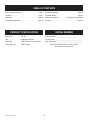 2
2
-
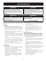 3
3
-
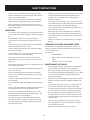 4
4
-
 5
5
-
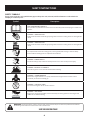 6
6
-
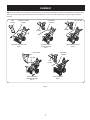 7
7
-
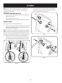 8
8
-
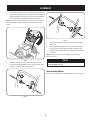 9
9
-
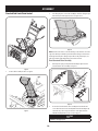 10
10
-
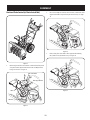 11
11
-
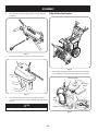 12
12
-
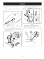 13
13
-
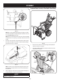 14
14
-
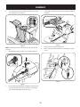 15
15
-
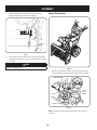 16
16
-
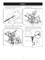 17
17
-
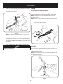 18
18
-
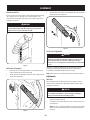 19
19
-
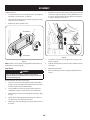 20
20
-
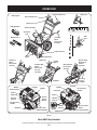 21
21
-
 22
22
-
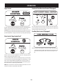 23
23
-
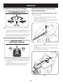 24
24
-
 25
25
-
 26
26
-
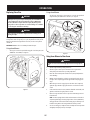 27
27
-
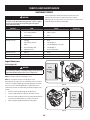 28
28
-
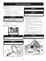 29
29
-
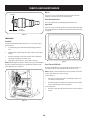 30
30
-
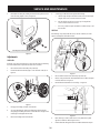 31
31
-
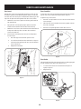 32
32
-
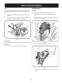 33
33
-
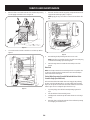 34
34
-
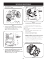 35
35
-
 36
36
-
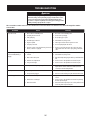 37
37
-
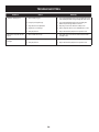 38
38
-
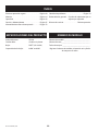 39
39
-
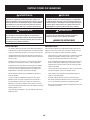 40
40
-
 41
41
-
 42
42
-
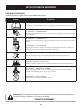 43
43
-
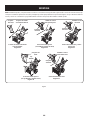 44
44
-
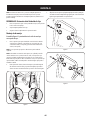 45
45
-
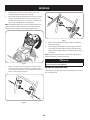 46
46
-
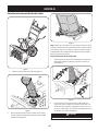 47
47
-
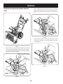 48
48
-
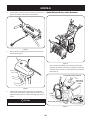 49
49
-
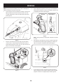 50
50
-
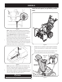 51
51
-
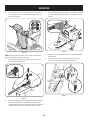 52
52
-
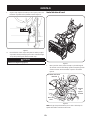 53
53
-
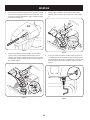 54
54
-
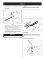 55
55
-
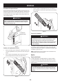 56
56
-
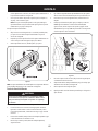 57
57
-
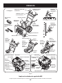 58
58
-
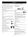 59
59
-
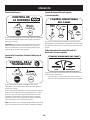 60
60
-
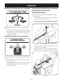 61
61
-
 62
62
-
 63
63
-
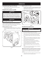 64
64
-
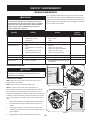 65
65
-
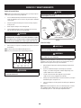 66
66
-
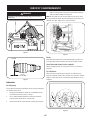 67
67
-
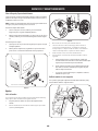 68
68
-
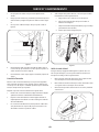 69
69
-
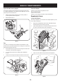 70
70
-
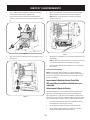 71
71
-
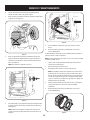 72
72
-
 73
73
-
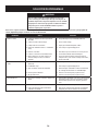 74
74
-
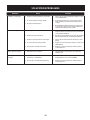 75
75
-
 76
76


Craftsman CMXGBAM1054541 Manual de usuario
- Categoría
- Lanzadores de nieve
- Tipo
- Manual de usuario
En otros idiomas
- English: Craftsman CMXGBAM1054541 User manual
Documentos relacionados
Otros documentos
-
Troy-Bilt 31CM6CP3B66 Manual de usuario
-
Cub Cadet 31AH7EVZ710 Manual de usuario
-
Cub Cadet 31AH7EVZ710 Manual de usuario
-
-
Troy-Bilt 31AH8E4V710 Manual de usuario
-
-
MTD 800 Series Manual de usuario
-
-
-
MTD 700 Series Manual de usuario