Artic King AKPD-12CR4 El manual del propietario
- Categoría
- Acondicionadores de aire móviles
- Tipo
- El manual del propietario


Inside you will find many helpful hints on how to use and maintain your air conditioner
properly. Just a little preventive care on your part can save you a great deal of time
and money over the life of your air conditioner. You'll find many answers to common
problems in the chart of troubleshooting tips. If you review o ur c hart o f T roubleshooting
Tips first, you may not need to call for service at all.
Read This Manual
CAUTION
This appliance can be used by children aged from 8 years and above and persons
with reduced physical, sensory or mental capabilities or lack of experience and
knowledge if they have been given supervision or instruction concerning use of the
appliance in a safe way and understand the hazards involved. Children shall not play
the appliance. Cleaning and user maintenance shall not be made by children without
supervision. ( be applicable for the European Countries )
This appliance is not intended for use by persons (including children) with reduced
physical ,sensory or mental capabilities or lack of experience and knowledge, unless
they have been given supervision or instruction concerning use of the appliance by a
person responsible for their safety. (be applicable for other countries except the
European Countries )
Children should be supervised to ensure that they do not play with the appliance.
If the supply cord is damaged, it must be replaced by the manufacturer, its service
agent or similarly qualified persons in order to avoid a hazard.
The appliance shall be installed in accordance with national wiring regulations.
Do not operate your air conditioner in a wet room such as a bathroom or laundry room.
The appliance with electric heater shall have at l east 1 m eter s pace t o t he c ombustible
materials.
Contact the authorised service technician for repair or maintenance of this unit.
Contact the authorised installer for installation of this unit.
!
Downloaded from www.Manualslib.com manuals search engine

CONTENTS
SOCIABLE REMARK
Sociable remark..................................................................................................................................2
The rating data indicated on the energy label is based
on the testing condition of installing the un-extended
air exhaust duct without adaptor A & B (The duct and
the adaptor A & B are listed in the accessories chart
of the Instruction Manual).
NOTE
1
SAFETY PRECAUTIONS
Safety rules .......................................................................................................................................3
Operating condition ...........................................................................................................................3
Electrical information .........................................................................................................................4
Accessories .......................................................................................................................................4
Names of parts...................................................................................................................................5
Electronic control operating instructions ...........................................................................................6
Operating instructions .......................................................................................................................7
Location ............................................................................................................................................9
Window kit installation ......................................................................................................................9
Exhaust hose installation ................................................................................................................12
Water drainage ................................................................................................................................13
Care and maintenance ....................................................................................................................14
Trouble shooting ..............................................................................................................................15
AIR CONDITIONER FEATURES
CARE AND MAINTENANCE
TROUBLESHOOTING TIPS
OPERATING INSTRUCTIONS
INSTALLATION INSTRUCTIONS
IDENTIFICATION OF PARTS
Downloaded from www.Manualslib.com manuals search engine

2
SOCIABLE REMARK
DISPOSAL: Do not dispose this product as unsorted municipal waste. Collection of
such waste separately for special treatment is necessary.
It is prohibited to dispose of this appliance in domestic household waste.
For disposal, there are several possibilities:
A) The municipality has established collection systems, where electronic waste can be
disposed of at least free of charge to the user.
B) When buying a new product, the retailer will take back the old product at least free
of charge.
C) The manufacture will take back the old appliance for disposal at least free of charge
to the user.
D) As old products contain valuable resources, they can be sold to scrap metal dealers.
Wild disposal of waste in forests and landscapes endangers your health when
hazardous substances leak into the ground-water and find their way into the food chain.
When using this air conditioner in the European countries, the following informa-
tion must be followed:
CAUTION:
This appliance is not intended for use by persons (including children) with
reduced physical,sensory or mental capabilities, or lack of experience and
knowledge, unless they have been given supervision or instruction concerning
use of the appliance by a person responsible for their safety.
Children should be supervised to ensure that they do not play with the appliance.
Downloaded from www.Manualslib.com manuals search engine

3
To prevent injury to the user or other people and property damage, the following instructions must be
followed. Incorrect operation due to ignoring of instructions may cause harm or damage.
Your air conditioner should be used in such a way
that it is protected from moisture. e.g. condensation,
splashed water, etc. Do not place or store your air
conditioner where it can fall or be pulled into water
or any other liquid. Unplug immediately.
Always transport your air conditioner in a vertical
position and stand on a stable, level surface during
use.
Turn off the product when not in use.
Always contact a qualified person to carry out
repairs. If the supply cord is damaged it must be
repaired by a qualified repairer.
Keep an air path of at least 30cm all around the
unit from walls, furniture and curtains.
If the air conditioner is knocked over during use,
turn off the unit and unplug from the mains supply
immediately.
SAFETY PRECAUTIONS
!
Always do this
Do not operate your air conditioner in a wet room
such as a bathroom or laundry room.
Do not touch the unit with wet or damp hands or
when barefoot.
Do not press the buttons on the control panel with
anything other than your fingers.
Do not remove any fixed covers. Never use this
appliance if it is not working properly, or if it has
been dropped or damaged.
Never use the plug to start and stop the unit.
Always use the switch on the control panel.
Do not cover or obsturct the inlet or outlet grilles.
Do not use hazardous chemicals to clean or come
into contact with the unit. Do not use the unit in the
presence of inflammable substances or vapour such
as alcohol, insecticides, petrol,etc.
Do not allow children to operate the unit
unsupervised.
Do not use this product for functions other than
those described in this instruction manual.
Never do this
Energy Save
Use the unit in the recommended room size.
Locate the unit where furniture cannot obstruct the air flow.
Keep blinds/curtains closed during the sunniest part of the day.
Keep the filters clean.
Keep doors and windows closed to keep cool air in and warm air out.
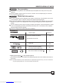
The air conditioner must be operated within the temperature range indicated below:
Operating condition
Safety rules
Suggested tools for window kit installation
1. Screwdriver(medium size Phillips)
2. Tape measure or ruler
3. Knife or scissors
4. Saw(In the event that the window kit needs to be cut down in size because
the window is too narrow for direct installation)
MODE ROOM TEMPERATURE
COOL
DRY
O O
17 C(62 F)~35O O
C(95 F)
O O
13 C(55 F)~35O O
C(95 F)
HEAT(heat pump type) O O
5 C(41 F)~ O O
30 C(88 F)
HEAT(electrical heat type)
O O
<30 C/88 F
Downloaded from www.Manualslib.com manuals search engine

4
Be sure the electrical service is adequate for the model you have chosen. This information can be found
on the serial plate, which is located on the side of the cabinet and behind the grille.
Be sure the air conditioner is properly grounded. To minimize shock and fire hazards, proper grounding is
important. The power cord is equipped with a three-prong grounding plug for protection against shock
hazards.
Your air conditioner must be used in a properly grounded wall receptacle. If the wall receptacle you intend
to use is not adequately grounded or protected by a time delay fuse or circuit breaker, have a qualified
electrician install the proper receptacle.
Ensure the receptacle is accessible after the unit installation.
WARNING For your safety
Do not store or use gasoline or other flammable vapors and liquids in the vicinity of this or any other
appliance.
Avoid fire hazard or electric shock. Do not use an extension cord or an adaptor plug. Do not remove
any prong from the power cord.
WARNING Electrical Infor mation
IDENTIFICATION OF PARTS
Accessories
Check all the accessories are included in the package and please refer to the installation instructions for
their usage.
PARTS :
PARTS NAME :
Exhaust hose and Apaptor and Adaptor BI
QUANTITY :
1 set
Window Slider Kit and bolt
Foam seal
3/pc
TEMP
AUTO
COOL
DRY
HEAT
FAN
HIGH
MED
LOW
MODE
FAN SPEED
SWING
TIMER ON
ECONOMY
ON/OFF
TIMER OFF
RESET LOCK
SET TEMPERATURE( C)
FOLLOW
ME LED
DISPLAY
ION
TURBO
Remote Controller and Battery
(For remote control models only)
1pc
Drain hose and drain hose adaptor( )
1pc
All the illustrations in this manual are for explanation purpose only. Your air conditioner
may be slightly different. The actual shape shall prevail.
NOTE:
NOTE: Optional parts( ), some models without.
Downloaded from www.Manualslib.com manuals search engine

IDENTIFICATION OF PARTS
5
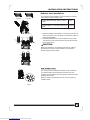
NAMES OF PARTS
Front
Rear
Operation panel
Horizontal louver blade
(swing automatically)
Caster
Carrying handle
(both sides)
3
1
2
3
4
6
7
8
9
10
11
Air intake
12
Fig.1
13
1
2
4
Fig.2
5Air filter
(Behind the grille)
Air outlet
Drain outlet (only for Pump
heating model)
Power cord outlet
Power cord buckle (Used
only when storing the unit)
Bottom tray drain outlet
Power plug socket (Use
only when storing the unit)
Vent control
16
5
7
6
9
8
10
11 12
13
15
14
15
Air filter
Air intlet
14
16
Drain outlet
CLOSE
OPEN
Downloaded from www.Manualslib.com manuals search engine

6
AIR CONDITIONER FEATURES
Before you begin, thoroughly familiarize yourself with the control panel and remote controller
and all its functions, then follow the symbol for the functions you desire.
The unit can be controlled by the unit control panel alone or with the remote controller .
ELECTRONIC CONTROL OPERATING INSTRUCTIONS
Fig.3
NOTE: This manual does not include Remote Controller Operations, see the <<Remote
Controller Instruction>> packed with the unit for details.
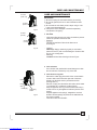
OPERATION PANEL OF THE AIR CONDITIONER
1
5
3
4
Used to initiate the SLEEP operation.
SLEEP button
Control the fan speed. Press to select the fan
speed in four steps-LOW, MED, HI and AUTO.
The fan speed indicator light illuminates under
different fan settings except AUTO speed. When
select AUTO fan speed, all the fan indicator lights
turn dark.
NOTE: Press this button for 3 seconds to initiate
ION feature.The ion generator is energized and will
help to remove pollen and impur ities from the air, and
trap them in the filter. Press it for 3 seconds again to
stop the ION feature.
FAN/ION button
1
2344567
8
9
Selects the appropriate operating mode.
Each time you press the button, a mode
is selected in a sequence that goes from
AUTO, COOL, DRY, FAN and HEAT(cooling
only models without). The mode indicator
light illuminates under the different mode
settings.
MODE select button
Power switch on/off.
POWER button
2
Used to adjust (increasing/decreasing)
temperature settings(1 C/2 F increments)
in a range of 17 C(62 F) to 30 C(88 F) or
the TIMER setting in a range of 0~24hrs..
UP( ) and DOWN( ) button
NOTE: The control is capable of displaying
temperature in degrees Fahrenheit or degrees
Celsius. To convert from one to the other, press
and hold the Up and Down buttons at the same
time, for 3 seconds.
+-
6TIMER button
Used to initiate the AUTO ON start time and
AUTO OFF stop time program, in conjuction
with the & buttons. The timer on/off
indicator light illuminates under the timer
on/off settings.
+-
7SWING button
(Applicable to the models with auto swing feature only)
Used to initiate the Auto swing feature.
When the operation is ON, press the
SWING button can stop the louver at
the desired angle.
(ION is optional)
O
Shows the set temperature in C
O
" F" and the Auto-timer settings.
While on DRY and FAN modes, it shows
the room temperature.
" " or
LED Display
8
FAN
Downloaded from www.Manualslib.com manuals search engine

7
OPERATING INSTRUCTIONS
Operating Instructions
- Press the "MODE" button until the "COOL"
indicator light comes on.
- Press the ADJUST buttons "+" or " - " to
select your desired room temperature. The
temperature can be set within a range of
O O O O
17 C-30 C/62 F-88 F.
- Press the "FAN SPEED" button to choose the
fan speed.
- Press the "MODE" button until the "DRY"
indicator light comes on.
- Under this mode, you cannot select a fan
speed or adjust the temperature. The fan
motor operates at LOW speed.
- Keep windows and doors closed for the
best dehumidifying effect.
- Do not put the duct to window.
COOL operation
- Press the "MODE" button until the
"FAN " indicator light comes on.
- Press the "FAN SPEED" button to
choose the fan speed. The temperature
cannot be adjusted.
- Do not put the duct to window.
FAN operation
TIMER operation
- Press the "MODE" button until the "HEAT"
indicator light comes on.
- Press the ADJUST buttons "+" or " - " to
select your desired room temperature. The
temperature can be set within a range of
O O O O
17 C-30 C/62 F-88 F.
- Press the "FAN SPEED" button to choose the
fan speed. For some models, the fan speed
can not be adjusted under HEAT mode.
HEAT operation(cooling only models without)
AUTO operation
- When you set the air conditioner in AUTO
mode, it will automatically select cooling,
heating(cooling only models without), or
fan only operation depending on what
temperature you have selected and the
room temperature.
- The air conditioner will control room
temperature automatically round the
temperature point set by you.
- Under AUTO mode, you can not
select the fan speed.
9FOLLOW ME/TEMP SENSING feature(optional)
To activate the Follow Me/Temp Sensing
feature, point the remote control towards
the unit and press the Follow Me/Temp
Sensing button. The remote display is
actual temperature at its location. The
remote control will send this signal to the
air conditioner every 3 minutes interval
until press the Follow Me/Temp Sensing
button again.If the unit does not receive
the Follow Me/Temp Sensing signal during
any 7 minutes interval, the unit will beep to
indicate the Follow Me/Temp Sensing mode
has ended.
NOTE:This feature can be activated from the
remote control ONLY. The remote control
servesas a remote thermostat allowing for the
precise temperature control at its location.
- When the unit is on, press the
Timer button will initiate the Auto-off
stop program, the TIMER OFF
indicator light illuminates. Press the
UP or down button to select the desired
time. Press the TIMER button again
within 5 seconds, the Auto-on start
program is initiated. And the TIMER
ON indicator light illuminates. Press
the up or down button to select the
desired Auto-on start time.
- When the unit is off, press the Timer
button to initiate the Auto-on start
program,press it again within five
seconds will initiate the Auto-off stop
program.
- Press or hold the UP or DOWN
button to change the Auto time by
0.5 hour increments, up to 10 hours,
then at 1 hour increments up to 24
hours. The control will count down
the time remaining until start.
- The system will automatically revert
back to display the previous temper-
ature setting if there is no operation
in a five seconds period.
Error codes and protection code:
E1- Room temperature sensor error-
Unplug the unit and plug it back in.
If error repeats, call for service.
E2- Evaporator temperature sensor error-
Unplug the unit and plug it back in.
If error repeats, call for service.
E3- Conenser temperature sensor error-
Unplug the unit and plug it back in. If error
repeats, call for service.
E4- Display panel communication error-
Unplug the unit and plug it back in.
If error repeats, call for service.
P1- Bottom tray is full - Connect the
drain hose and drain the collected
water away. If protection repeats, call
for service.
Downloaded from www.Manualslib.com manuals search engine

8
OPERATING INSTRUCTIONS
Fig.4
Other features
After the unit has stopped, it can not be restarted
operation in the first 3 minutes. This is to protect
the unit. Operation will automatically start after
3 minutes.
Wait 3 minutes before resuming operation
SLEEP operation
Press this button, the selected temperature will
O O
increase(cooling) or decrease(heating) by 1 C/2 F
30 minutes.The temperature will then increase
O O
(cooling) or decrease (heating) by another 1 C/2 F
after an additional 30 minutes. This new temper-
ature will be maintained for 7 hours before it returns
to the originally selected temperature. This ends
the Sleep mode and the unit will continue to operate
as originally programmed.
NOTE: This feature is unavailabe under FAN or
DRY mode.
If the unit breaks off unexpectedly due to the
power cut,it will restart with the previous
function setting automatically when the
power resumes.
Auto-Restart(on some models)
- Turning the unit ON or OFF at any
time or adjusting the timer setting
to 0.0 will cancel the Auto Start/
Stop timer program.
- When the malfunction (E1,E2,E3
or E4) occurs, the Auto Start/Stop
timed program will also be cancelled.
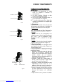
The louver can be adjusted automatically .
Adjust the air flow direction automatically
(Fig.4):
When the Power is ON, the louver opens fully.
Press the SWING button on the panel or
remote controller to initiate the Auto swing
feature.
The louver willl swing up and down
automatically.
Please do not adjust the louver manually.
Air flow direction adjustment
Swing automatically
Downloaded from www.Manualslib.com manuals search engine

INSTALLATION INSTRUCTIONS
Location
The air conditioner should be placed on a firm
foundation to minimize noise and virbration. For
safe and secure positioning, place the unit on a
smooth, level floor strong enough to support the unit.
The unit has casters to aid placement, but it should
only be rolled on smooth, flat surfaces. Use caution
when rolling on carpet surfaces. Do not attempt to
roll the unit over objects.
The unit must be placed within reach of a properly
rated grounded socket.
Never place any obstacles around the air inlet or
outlet of the unit.
Allow 30cm to 100cm of space from the wall with
for efficient air-conditioning.
Your window slider kit has been designed to fit most
standard "Vertical" and "horizontal"window
applications, However, it may be necessary for you to
improvise/modify some aspects of the installation
procedures for certain types of window. Please refer
to Fig. 6 & Fig.7 for minimum and maximum window
openings.Window slider kit can be fixed with a bolt
(see Fig.7a).
Window slider kit Installation
Note: If the window opening is less than the mentioned
minimum length of the window slider kit, cut that one
with a hole in it short to fit for the window opening.
Do never cut out the hole in window slider kit.
INSTALLATION INSTRUCTIONS(optional)
9
bolt
Window slider kit
Fig.7a
A:30cm-100cm B:≥30cm
Fig.5
B
A
Horizontal
window
Window Slider Kit
Minimum:67.5cm(2.22ft).
Maxmum:123cm(4.04ft).
Fig.6
Horizontal
window
Fig.7
Window Slider Kit
Minimum:67.5cm(2.22ft).
Maxmum:123cm(4.04ft).
Downloaded from www.Manualslib.com manuals search engine

INSTALLATION INSTRUCTIONS(optional)
10
Installation in a double-hung sash
window
1. Cut the foam seal(adhesive type) to the proper length and
attach it to the window stool. Fig.8
2. Attach the window slider kit to the window stool. Adjust the
length of the window slider kit according to the width of
window, shorten the adjustable window kit if the width of
window is less than 26.5 inches
Open the window sash and place the window slider kit on
the window stool. Fig.9
3. Cut the foam seal(adhesive type) to the proper length
and attach it on the top of the window. Shown as in Fig.10
4. Close the window sash securely against the window.
5. Cut the foam seal to an appropriate length and seal the
open gap between the top window sash and outer window
sash. Shown as in Fig.11.
Foam seal A
(adhesive type)
Foam seal
Fig.8
Fig.9
Fig.10
Fig.11
Window kit
Window stool
Window kit
Window stool
26.5 ~ 48.0
Downloaded from www.Manualslib.com manuals search engine

INSTALLATION INSTRUCTIONS(optional)
11
Installation in a sliding sash window
1. Cut the foam seal(adhesive type) to the proper length and
attach it to the window frame. See Fig.12.
2. Attach the window slider kit to the window stool. Adjust the
length of the window slider kit according to the width of
window, shorten the adjustable window kit if the width of
window is less than 26.5 inches.
Open the window sash and place the window slider kit on
the window stool. See Fig.13.
3. Cut the foam seal(adhesive type) to the proper length
and attach it on the top of the window. Shown as in Fig.14.
4. Close the sliding sash securely against the window.
5. Cut the foam seal to an appropriate length and sea the
open gap between the top window sash and outer window
sash. Shown as in Fig.15.
Foam seal
Foam seal A
(adhesive type)
Fig.12
Fig.13
Fig.14
Fig.15
Window
panel
NOTE:All the illustrations in this manual are for explanation
purpose only.Your unit may be slightly different. The
actual shape shall prevail.
26.5 ~ 48.0
Downloaded from www.Manualslib.com manuals search engine

INSTALLATION INSTRUCTIONS
Exhaust hose installation:
The exhaust hose and adaptor must be installed or removed
in accordance with the usage mode.
1. Install the adaptor B and adaptor I onto the exhaust hose as
shown in Fig.16a or Fig.16b. Refer to the previous pages for
window kit installation.
2. Install the flexible Exhaust hose as depicted in Fig.17a&b.
Then push the hook of the Exhaust hose into the hole seat
of the unit in Fig.18.
12
Fig.16a
Fig.17a
Fig.16b
COOL,HEAT(heat pump type) or AUTO
mode
FAN,DEHUMIDIIFY or HEAT(electrical heat type)
mode
Install
Remove
CAUTION:
Make sure that there is no obstacle around the air outlet of
the exhaust hose (in the range of 500mm) in order to the
exhaust system works properly.
Fig.17b
Hole seat
Hook
Hook
Hook
Hole seat
Fig.18
Push Push
CLOSE
OPEN
VENT CONTROL feature
The Vent Control is located at the back of the air conditioner.
The OPEN position removes stale air from the room and
exhausts it to the outside. Fresh air is drawn in through normal
passages in the home.
When not need to circulate the room air, set Vent Control to
CLOSE position.
Fig.19
Downloaded from www.Manualslib.com manuals search engine

INSTALLATION INSTRUCTIONS
Water drainage:
- During dehumidifying modes, remove the upper
drain plug from the back of the unit, install the drain
connector(5/8 universal female mender) with
3 4 hose(locally purchased). For the models
without drain connector, just attach the drain
hose to the hole. Place the open end of the hose
adaptor directly over the drain area in your
basement floor. Please refer to Fig.20a.
NOTE: For the double-duct design, the water drainage
is not needed during cooling operation. If performing
above water drainage during cooling operation, the
cooling efficiency will be reduced.
- During heating pump mode, remove the lower drain
plug from the back of the unit, install the drain
connector(5/8 universal female mender) with
3/4 hose(locally purchased). For the models
without drain connector, just attach the drain
hose to the hole. Place the open end of the hose
adaptor directly over the drain area in your
basement floor. Please refer to Fig.20b.
- When the water level of the bottom tray reaches
a predetermined level,
Carefully move the unit to a drain location,
remove the bottom drain plug and let the
water drain away(Fig.22). Reinstall the bottom
drain plug and restart the machine until the "P1"
symbol disappears. If the error repeats, call for
service.
the unit beeps 8 times,
the digital display area shows "P1" . At this time
the air conditioning/dehumidification process will
immediately stop. However, the fan motor will
continue to operate(this is normal).
Remove the
upper drain plug
Continuous
drain hose
Fig.20a
Fig.20b
13
Fig.22
NOTE: Be sure to reinstall the bottom drain plug
before using the unit.
Remove the
upper drain plug
Continuous
drain hose
drain hose
adaptor
drain hose
adaptor
NOTE:
Make sure the hose is secure so there are
no leaks.Direct the hose toward the drain,making
sure that there are no kinks that will stop the warter
flowing.Place the end of the hose into the drain and
make sure the end of the hose is down tolet the
water flow smoothly.(See Fig.20a,20b,21a).Do
never let it up.(See Fig.21b).
Fig.21b
Fig.21a
√×
√
√
Downloaded from www.Manualslib.com manuals search engine

CARE AND MAINTENANCE
CARE AND MAINTENANCE
1) Be sure to unplug the unit before cleaning or servicing.
2) Do not use gasoline, thinner or other chemicals to clean
the unit.
3) Do not wash the unit directly under a tap or using a hose.
It may cause electrical danger.
4) If the power cord is damaged, it should be repaired by
manufacture or its agency.
IMPORTANT:
1. Air filter
2. Unit enclosure
- Use a lint-free cloth soaked with neutral detergent to clean
the unit enclosure. Finished by a dry clean cloth.
Fig.23
3. Unit idle for a long time
14
- Remove the rubber plug at the back of the unit and attach
a hose to drain outlet. Place the open end of the hose
directly over the drain area in your basement floor
(See Fig.20 & 21).
- Remove the plug from the bottom drain outlet, all the water
in the bottom tray would drain out (See Fig.22).
- Keep the appliance running on FAN mode for half a day in
a warm room to dry the appliance inside and prevent mold
forming.
- Stop the appliance and unplug it, wrapped the cord and
bundle it with the tape(Fig.25). Remove the batteries from
the remote controller.
- Clean the air filter and reinstall it.
Fig.24
Fig.25
Buckle
Power
cord
Air filter
(take out)
Air filter
(install)
- Clean the air filter at least once every two weeks to prevent
inferior fan operation because of dust.
- Removal
This unit has two filters. Take the air filters out as
shownFig.23.
- Cleaning
Wash the air filter by immersing it gently in warm water
O O
(about 40 C/104 F) with a neutral detergent. Rinse the filter
and dry it in a shady place.
- Mounting
Install the air filters after cleaning as shown Fig.24..
Power plug
socket
Power plug
Air filter
(take out)
Air filter
(install)
Downloaded from www.Manualslib.com manuals search engine

TROUBLESHOOTING TIPS
TROUBLE SHOOTING
1. Unit does not
Start when
Pressing on/off
Button
- P1 appears in the display window
Drain the water in the bottom tray.
TROUBLES
POSSIBLE CAUSES
SUGGEST REMEDIES
Reset the temperature.
Make sure all the windows and
doors are closed.
Remove the heat sources if possible.
Connect the duct and make
sure it can function properly.
Decrease the set temperature.
Clean the air filter.
- Room temperature is lower than
the set temperature.(Cooling mode)
- The windows or doors in the room
are not closed.
- There are heat sources inside the
room.
- Exhaust air duct is not connected or
blocked.
- Temperature setting is too high.
- Air filter is blocked by dust.
2. Not cool enough
Place the unit on a flat, level
ground if possible.
It is normal.
- The ground is not level or not flat
enough.
- The sound comes from the flowing
of the refrigerant inside the
air-conditioner.
4. Noisy or vibration
5. Gurgling sound
15
Switch on again after the unit
has cool down.
- The automatic over heat
protection function. When the
temperature at the air outlet
O O
exceed 70 C/158 F,th e de vice
will st
op.
6. Power shut off at
Heating mode
Downloaded from www.Manualslib.com manuals search engine

Arctic King Air Conditioner Limited Warranty
Your product is protected by this Limited Warranty:
Warranty service must be obtained from Arctic King Consumer Services or an authorized Arctic King
servicer.
Warranty
One year full warranty from original purchase date.
Arctic King, through its authorized servicers will:
Pay all costs for repairing or replacing parts of this appliance which prove to be defective in materials or workmanship.
Consumer will be responsible for:
Diagnostics, removal, transportation and reinstallation cost required because of service.
Costs of service calls that are a result of items listed under NORMAL RESPONSIBILITIES OF THE CONSUMER**
Arctic King replacement parts shall be used and will be warranted only for the period remaining on the original
warranty.
NORMAL RESPONSIBILITIES OF THE CONSUMER**
This warranty applies only to products in ordinary household use, and the consumer is responsible for the items listed below:
1. Proper use of the appliance in accordance with instructions provided with the product.
2. Routine maintenance and cleaning necessary to keep the good working condition.
3. Proper installation by an authorized service professional in accordance with instructions provided with the appliance and in
accordance with all local plumbing, electrical and / or gas codes.
4. Proper connection to a grounded power supply of sufficient voltage, replacement of blown fuses, repair of loosen connections or
defects in house wiring.
5. Expenses for making the appliance accessible for servicing.
6. Damages to finish after installation.
EXCLUSIONS
This warranty does not cover the following:
1) Failure caused by damage to the unit while in your possession (other than damage caused by defect or malfunction), by its
improper installation, or by unreasonable use of the unit, including without limitation, failure to provide reasonable and necessary
maintenance or to follow the written Installation and Operating Instructions.
2) Damages caused by services performed by persons other than authorized Arctic King servicers; use of parts other than Arctic
King replacement parts; obtained from persons other than such Arctic King customer service; or external causes such as abuse,
misuse, inadequate power supply or acts of God.
3) If the unit is put to commercial, business, rental, or other use or application other than for consumer use, we make no warranties,
express or implied, including but not limited to, any implied warranty of merchantability or fitness for particular use or purpose.
4) Products without original serial numbers or products that have serial numbers which have been altered or cannot be readily
determined.
Note: Some states do not allow the exclusion or limitation of incidental or consequential damages. So this limitation or exclusion may not
apply to you.
IF YOU NEED SERVICE
Keep your bill of sale, delivery slip, or some other appropriate payment record.
The date on the bill establishes the warranty period, should service be required.
If service is performed, it is your best interest to obtain and keep all receipts.
This written warranty gives you specific legal rights. You may also have other rights that vary from state to state.
Service under this warranty must be obtained by following these steps, in order:
1. Contact Arctic King Consumer Services or an authorized Arctic King servicer at 1 866 646 4332.
2. If there is a question as to where to obtain service, contact our consumer relations Department.
Downloaded from www.Manualslib.com manuals search engine


Modelo:
AIRE ACONDICIONADO PORTATIL
En este manual usted puede encontrar muchas indicaciones útiles sobre cómo usar y mantener su aire
acondicionado de manera correcta. Únicamente algunos cuiddados preventativos en su máquina puede
ahorrarle mucho tiempo y dinero durante la vida de su aire acondicionado. Antes del uso de este producto,
por favor lea las instrucciones con cuidadosamente y guarde este manual para el uso en el futuro.
AKPD-12CR4
AKPD-12ER4
Downloaded from www.Manualslib.com manuals search engine


Lea el siguiente manual
En el siguiente manual, usted encontrará varios consejos sobre cómo utilizar y mantener su
acondicionador de aire correctamente. Si toma las medidas preventivas correspondientes, podrá
ahorrar una gran cantidad de tiempo y dinero durante la vida útil de su producto. También encontrará
varias respuestas a problemas recurrentes en el cuadro sobre consejos para solucionar problemas. Si
primero se dirige a dicho cuadro, no será necesario que llame para solicitar ayuda.
PRECAUCIÓN
Este electrodoméstico solo puede ser utilizado por niños mayores de 8 años. Las personas
cuyas capacidades físicas, sensoriales o mentales estén reducidas o que no tengan
experiencia podrán utilizarlo si son supervisados o si los han instruido sobre la utilización del
electrodoméstico de forma segura y si comprenden los riegos posibles. Los niños no deben
jugar con el electrodoméstico y tampoco podrán realizar tareas de limpieza o mantención sin
ser supervisados por un mayor (aplicable para los países europeos).
Este electrodoméstico no está preparado para ser utilizado por personas (inclusive niños) con
capacidades físicas, sensoriales o mentales reducidas o sin experiencia ni conocimiento, a
menos que reciban supervisión o instrucciones sobre cómo utilizar el electrodoméstico por
parte de la persona responsable de su seguridad.
Los niños deben ser supervisados para evitar que jueguen con el electrodoméstico.
Si el cable de alimentación está dañado, el fabricante, agente de reparación o cualquier
persona igualmente calificada debe reemplazarlo para evitar riesgos.
El electrodoméstico debe instalarse de acuerdo a las normas nacionales de cableado.
No utilice el acondicionador de aire en un ambiente húmedo, como un baño o lavadero.
El electrodoméstico y el calentador eléctrico deben estar separados por al menos 1 metro para
materiales inflamables.
Contacte a técnicos en reparación autorizados para la reparación o mantenimiento de esta
unidad.
Contacte a instaladores autorizados para la instalación de esta unidad.
Downloaded from www.Manualslib.com manuals search engine

CONTENIDOS
REGLAS DE DISPOSICIÓN DE RESIDUOS
Reglas de disposición de residuos……………………………………………………………….2
MEDIDAS DE SEGURIDAD
Normas de seguridad………………………………………………………………………………3
Condición de operación……………………………………………………………………………3
Información sobre la electricidad…………………………………………………………………4
IDENTIFICACIÓN DE LAS PARTES
Accesorios…………………………………………………………………………………………..4
Nombres de las partes……………………………………………………………………………..5
CARACTERÍSTICAS DEL ACONDICIONADOR DE AIRE
Instrucciones de operación de control electrónico……………………………………………...6
INSTRUCCIONES DE OPERACIÓN
Instrucciones de operación………………………………………………………………………..7
INSTRUCCIONES DE INSTALACIÓN
Ubicación……………………………………………………………………………………………9
Instalación del conjunto de ventana……………………………………………………………...9
Instalación de la manguera de escape…………………………………………………………12
Drenaje de agua…………………………………………………………………………………..13
CUIDADO Y MANTENIMIENTO
Cuidado y mantenimiento………………………………………………………………………..14
CONSEJOS PARA SOLUCIONAR PROBLEMAS
Solución de problemas…………………………………………………………………………...15
NOTA
Los datos de calificación indicados en la etiqueta
energética se basan en la condición de prueba de la
instalación del ducto de escape de aire no extendido
sin adaptador A & B (el ducto y el adaptador A & B se
enumeran en la tabla de accesorios para el manual de
instrucciones).
Downloaded from www.Manualslib.com manuals search engine

REGLAS DE DESECHADO DE RESIDUOS
Al utilizar este acondicionador de aire en países europeos, se debe prestar atención
a la siguiente información:
DESECHADO: No deseche este producto junto con otros tipos de residuos municipales.
Es necesario recolectar dichos residuos en forma separada para que reciban un
tratamiento especial.
Está prohibido desechar este electrodoméstico junto con residuos domésticos.
Para desecharlo existen las siguientes posibilidades:
A) La municipalidad ha establecido sistemas de recolección, en los que los residuos
electrónicos deben desecharse sin cargo alguno para el usuario.
B) Al comprar un producto nuevo, el vendedor recibirá el producto viejo sin cargo
alguno.
C) El fabricante recibirá el producto viejo para desecharlo sin cargo alguno para el
usuario.
D) Dado que los productos viejos contienen elementos valiosos, estos pueden
venderse a chatarreros.
Desechar residuos en bosques u otros paisajes pone en riesgo su salud, si sustancias
peligrosas se filtran en el agua del suelo y, como consecuencia, aparecen en la cadena de
alimentación.
PRECAUCIÓN:
Este electrodoméstico no está preparado para ser utilizado por personas (inclusive
niños) con capacidades físicas, sensoriales o mentales reducidas o sin experiencia
ni conocimiento, a menos que reciban supervisión o instrucciones sobre cómo
utilizar el electrodoméstico por parte de la persona responsable de su seguridad.
Los niños deben ser supervisados para evitar que jueguen con el electrodoméstico.
Downloaded from www.Manualslib.com manuals search engine

PRECAUCIONES DE SEGURIDAD
Normas de seguridad
Para evitar lesiones al usuario o a otras personas y daños materiales, debe seguir las siguientes
instrucciones. El uso incorrecto ocasionado al ignorar las instrucciones puede causar lesiones o
daños.
Haga esto siempre
Nunca haga esto
Su aire acondicionado debe usarse de tal manera que
quede protegido de la humedad, por ejemplo
condensación, salpicaduras de agua, etc. No coloque
ni almacene su aire acondicionado en donde pueda
caerse o ser empujado en el agua o cualquier otro
líquido. Desenchufe la unidad inmediatamente.
Trasporte siempre su aire acondicionador en posición
vertical y sobre una superficie estable, plana durante
el uso.
Apague el producto cuando no esté en uso.
Siempre contacte a una persona cualificada para
llevar a cabo las reparaciones. Si el cable de
alimentación está dañado, debe ser reparado por un
taller de reparación calificado.
Mantenga una ruta aérea de al menos 30 cm
alrededor del aparato de paredes, muebles y cortinas.
Si el aire acondicionador se vuelca durante el uso,
apague la unidad y desconecte de la red eléctrica
inmediatamente.
No utilice el aire acondicionador en una habitación
húmeda como cuarto de baño o la lavandería.
No toque la unidad con las manos húmedas o
mojadas o con los pies descalzos.
No presione los botones sobre el panel de control con
algo más que los dedos.
No quite ninguna cubierta fija. Nunca utilice este
aparato si no funciona correctamente, o si se ha caído
o dañado.
Nunca use el enchufe para encender y apagar la
unidad.
Utilice siempre el interruptor en el panel de control.
No cubra ni obstruya las rejillas de entrada o de
salida.
No utilice productos químicos peligrosos para limpiar o
entrar en contacto con la unidad. No utilice la unidad
en la presencia de sustancias inflamables o el vapor
como el alcohol, insecticidas, gasolina, etc.
No permita que los niños utilicen el aparto sin
supervisión.
No utilice este producto para funciones distintas de las
descritas en este manual de instrucciones.
Ahorro de Energía
Use la unidad en las habitaciones de tamaño recomendado.
Coloque la unidad en donde los muebles no pueden obstruir el flujo de aire.
Mantenga las persianas/cortinas cerradas durante el día soleado.
Mantenga limpios los filtros.
Mantenga las puertas y ventanas cerradas para mantener el aire fresco entrante y el aire caliente saliente.
Condiciones de funcionamiento
El aire acondicionado debe funcionar dentro del rango de temperatura que se indica a
continuación:
MODO
TEMPERATURA AMBIENTE
FRIO
17℃~35℃/62℉~95℉
Deshumidificación
13℃~35℃/54℉~95℉
CALOR
5℃~30℃/41℉~86℉
CALOR (del tipo bomba de calor)
5℃(41℉)~30℃(88℉)
CALOR (del tipo calor eléctrico)
≤30℃/88℉
Herramientas sugeridas para instalar el juego de ventana
1. Destornillador (de tamaño mediano; Phillips)
2. Cinta métrica o regla
3. Cuchillo o tijera
4. Sierra (en el caso de que el juego de ventana necesite ser cortado porque la ventana es muy
pequeña y no encaja)
Downloaded from www.Manualslib.com manuals search engine

IDENTIFICACIÓN DE PARTES
ADVERTENCIA Para su seguridad
No almacene ni utilice gasolina y otros vapores y líquidos inflamables en las cercanías de este
o cualquier otro electrodoméstico.
Evite el riesgo de incendios o descargas eléctricas. No utilice un cable de extensión o un
adaptador de enchufe. No quite ninguna clavija del cable de alimentación.
ADVERTENCIA Información eléctrica
Asegúrese de que el servicio eléctrico sea apto para el modelo que ha elegido. Esta
información se puede encontrar en la placa de serie, que se encuentra al lado del gabinete y
detrás de la rejilla.
Asegúrese de que el aire acondicionador esté correctamente conectado a tierra. Para
minimizar el impacto y los riesgos de incendio, la conexión adecuada a tierra es importante. El
cable de alimentación está equipado con un enchufe de tres patas para la protección contra
los riesgos de choque.
Debe usar el aire acondicionador en un receptáculo de la pared de tierra. Si el receptáculo de
la pared que vaya a utilizar no está adecuadamente conectado a tierra o protegido por un
fusible de retardo o un interruptor de circuito, un electricista calificado tiene que instalar el
receptáculo apropiado.
Asegúrese de que el receptáculo sea accesible después de la instalación de la unidad.
Accesorios
PARTES:
NOMBRE DE LAS PARTES: CANTIDAD:
Manguera de escape y Adaptador B
Conjunto del deslizador de la ventana y bulón
1 conjunto
Sello de espuma
3 piezas
Controlador remoto y batería (solo para los
modelos con control remoto)
1 pieza
Manguera de drenaje y adaptador de la manguera
de drenaje (*)
1 pieza
NOTA: Partes opcionales (*), no incluidos en algunos modelos.
Controle que todos los accesorios estén incluidos en el paquete y refiérase a las instrucciones
de instalación para utilizarlos.
NOTA: Todas las ilustraciones del presente manual están incluidas solamente a modo explicativo. Su
acondicionador de aire puede ser ligeramente diferente. La forma real debe prevalecer.
TEMP
AUTO
COOL
DRY
HEAT
FAN
HIGH
MED
LOW
MODE
FAN SPEED
SWING
TIMER ON
ECONOMY
ON/OFF
TIMER OFF
RESET LOCK
SET TEMPERATURE( C)
FOLLOW
ME LED
DISPLAY
ION
TURBO
Downloaded from www.Manualslib.com manuals search engine

IDENTIFICACIÓN DE PARTES
NOMBRES DE LAS PARTES
Parte frontal
1. Panel de operación
2. Hoja de lama horizontal (giro
automático)
3. Rueda
4. Manija para transportar(ambos
lados)
Parte posterior
5. Filtro de aire (detrás de la rejilla)
6. Entra de aire
7. Salida de aire
8. Salida de drenaje (solo para el
modelo que tiene bomba de
calefacción)
9. Salida del cable de alimentación
10. Hebilla del cable de alimentación
(utilizada solamente para guardar
la unidad)
11. Salida de drenaje del fondo
12. Toma de corriente (utilizada
solamente para guardar la unidad)
13. Control de ventilación
14. Entrada de aire
15. Filtro de aire
16. Salida de drenaje
3
Fig.1
1
2
4
Fig.2
16
5
7
6
9
8
10
11 12
13
15
14
ABRIR
CERRAR
Downloaded from www.Manualslib.com manuals search engine

CARACTERÍSTICAS DEL AIRE ACONDICIONADO
INSTRUCCIONES DE OPERACIÓN DEL CONTROL ELECTRÓNICO
Antes de comenzar, familiarícese por completo con el panel de control y el control remoto
y todas sus funciones, entonces siga el símbolo de las funciones que desee.
La unidad puede controlarse con el panel de control o con el control remoto.
NOTA: Este manual no incluye las Operaciones del Control Remoto, vea los detalles
en las <<Instrucción del Control Remoto>> que vienen empacadas con la unidad.
PANEL DE OPERACIÓN DEL ACONDICIONADOR DE AIRE
Fig. 3
○
1 Botón de ENCENDIDO
Utilizado para encender o apagar el
producto.
○
2 Botón de REPOSO
Utilizado para iniciar el modo REPOSO.
○
3 Botón VENTILADOR/ION (ION es
opcional)
Controla la velocidad del ventilador.
Presiónelo para seleccionar la velocidad
del ventilador entre las siguientes cuatro:
BAJA, MEDIA, ALTA y AUTOMÁTICA.
La luz de indicador de la velocidad del
ventilador se ilumina de diferente forma,
excepto en el caso de la velocidad
AUTOMÁTICA. Cuando seleccione la
velocidad AUTOMÁTICA, todas las luces
indicadoras del ventilador se
oscurecerán.
NOTA: Presione este botón durante 3
segundos para iniciar la característica
ION. El generador ion se encenderá,
ayudará a remover polen e impurezas
del aire y las atrapará en el filtro.
Presiónelo nuevamente durante 3
segundos para detenerlo.
○
4 Botón MÁS (+) y MENOS (-)
Utilizado para ajustar
(aumentar/disminuir) la temperatura
(aumentos de a 1℃/2℉) en un rango de
17℃ (62℉) a 30℃ (88℉), o para ajustar
el temporizador en un rango de 0 a 24
horas.
NOTA: El control podrá mostrar la
temperatura en grados Fahrenheit o en
grados Celsius. Para convertir de una
medida a otra, presione al mismo tiempo el
botón de MÁS y el de MENOS durante 3
segundos.
○
5 Botón de selección del MODO
Selecciona el modo de operación
apropiado. Cada vez que presione el
botón, un modo se seleccionará en la
siguiente secuencia: AUTOMÁTICO,
FRÍO, SECO, VENTILADOR y CALOR
(el modo frío solo en modelos que
cuenten con el). La luz indicadora del
modo se iluminará de diferentes formas.
○
6 Botón de TEMPORIZADOR
Utilizado para configurar el horario de
ENCENDIDO y APAGADO
AUTOMÁTICO, con los botones + y -. La
luz indicadora del temporizador se
iluminará de diferentes formas.
○
7 Botón GIRAR
(Aplicable para aquellos modelos que
cuenten con la opción de giro automático)
Utilizado para iniciar la opción de giro
automático. Cuando el acondicionador
de aire esté funcionando, presione el
botón GIRAR para detener las aspas en
el ángulo deseado.
○
8 Pantalla LED
Muestra la temperatura en “℃” o en “℉”
y el temporizador. Mientras este en el
modo SECO o VENTILADOR, mostrará
la temperatura del ambiente.
1
2344567
8
9
FAN
Downloaded from www.Manualslib.com manuals search engine

INSTRUCCIONES DE OPERACIÓN
Códigos de errores y de protección:
E1- Error del sensor de temperatura del ambiente-
Desenchufe la unidad y vuelva a enchufarla. Si el
error se repite, llame para pedir asistencia técnica.
E2- Error del sensor de temperatura del
evaporador- Desenchufe la unidad y vuelva a
enchufarla. Si el error se repite, llame para pedir
asistencia técnica.
E3- Error del sensor de temperatura del
condensador- Desenchufe la unidad y vuelva a
enchufarla. Si el error se repite, llame para pedir
asistencia técnica.
E4- Error en la comunicación del panel de la
pantalla- Desenchufe la unidad y vuelva a
enchufarla. Si el error se repite, llame para pedir
asistencia técnica.
P1- La bandeja inferior está completa – Conecte la
manguera de drenaje y drene el agua acumulada.
Si la protección se repite, llame para pedir
asistencia técnica.
9. Opción SÍGUEME/SENSOR DE
TEMPERATURA (opcional)
NOTA: Esta opción SOLO podrá activarse
desde el control remoto. El control remoto sirve
como un termostato remoto que permite
controlar la temperatura precisa en su
ubicación.
Para activar la opción Sígueme/Sensor de
temperatura, apunte con el control remoto hacia la
unidad y presione el botón Sígueme/Sensor de
temperatura. La pantalla remota mostrará la
temperatura actual en su ubicación. El control
remoto enviará esta señal al acondicionador de
aire cada 3 minutos hasta que vuelva a presionar
el botón Sígueme/Sensor de temperatura. Si la
unidad no recibe la señal de Sígueme/Sensor de
temperatura durante 7 minutos, la unidad sonará
para indicar que el modo Sígueme/Sensor de
Temperatura ha finalizado.
Instrucciones de operación
Funcionamiento en modo FRÍO
- Presione el botón de “MODO” hasta que la luz
indicadora de “FRÍO” se encienda.
- Presione los botones de ajuste “+” y “-" para
seleccionar la temperatura ambiente que desee.
La temperatura puede variar entre 17℃ y 30℃
(62℉-88℉).
- Presione el botón “VELOCIDAD DEL
VENTILADOR” para seleccionar la velocidad del
ventilador.
Funcionamiento en modo CALOR (solo para
modelos sin opción de frío)
- Presione el botón de “MODO” hasta que la luz
indicadora de “CALOR” se encienda.
- Presione los botones de ajuste “+” y “-“ para
seleccionar la temperatura ambiente que desee.
La temperatura puede variar entre 17℃ y 30℃
(62℉-88℉).
- Presione el botón “VELOCIDAD DEL
VENTILADOR” para seleccionar la velocidad del
ventilador. En algunos modelos, la velocidad del
ventilador no puede ajustarse en el modo
CALOR.
- Presione el botón de “MODO” hasta que la luz
indicadora de “SECO” se encienda.
- En este modo, no puede seleccionar la velocidad
del ventilador ni ajustar la temperatura. El motor
del ventilador funcionar a una velocidad LENTA.
- Mantenga las ventanas y las puertas cerradas
para lograr un mejor efecto deshumidificador.
- No direccione el conducto hacia la ventana.
Funcionamiento en modo AUTOMÁTICO
- Cuando seleccione el modo AUTOMÁTICO, el
acondicionador de aire automáticamente
seleccionara el modo de funcionamiento frio,
calor (solo para modelos sin opción de frio) o
ventilador, según la temperatura que haya
seleccionado y la temperatura del ambiente.
- El acondicionador de aire controlará la
temperatura del ambiente automáticamente,
manteniéndola cerca de la temperatura
seleccionada por usted.
- En el modo AUTOMÁTICO, no puede seleccionar
la velocidad del ventilador.
Funcionamiento en modo VENTILADOR
- Presione el botón de “MODO” hasta que la luz
indicadora de “VENTILADOR” se encienda.
- Presione el botón “VELOCIDAD DEL
VENTILADOR” para seleccionar la velocidad del
ventilador.
- No direccione el conducto hacia la ventana.
Funcionamiento en modo TEMPORIZADOR
- Cuando la unidad esté encendida, presione el
botón de Temporizador para iniciar el programa
de apagado automático. La luz indicadora de
APAGADO PROGRAMADO se iluminará.
Presione el botón “+” o “-“ para seleccionar el
tiempo deseado. Presione nuevamente el botón
de TEMPORIZADOR durante 5 segundos para
iniciar el programa de encendido automático. La
luz indicadora de ENCENDIDO PROGRAMADO
se iluminará. Presione el botón “+” o “-“ para
seleccionar el tiempo de encendido deseado.
- Cuando la unidad esté apagada, presione el
botón de Temporizador para iniciar el programa
de encendido automático. Presiónelo
nuevamente durante cinco segundos para iniciar
el programa de apagado automático.
- Presione los botones MÁS o MENOS para
cambiar el tiempo en intervalos de 0.5 horas
hasta 10 horas, y en intervalos de 1 hora hasta
24 horas. El control contará el tiempo restante
hasta el inicio.
- El sistema volverá a mostrar automáticamente la
temperatura anterior, si no hay operación en un
periodo de cinco segundos.
Downloaded from www.Manualslib.com manuals search engine

INSTRUCCIONES DE OPERACIÓN
- Encender o apagar la unidad en cualquier
momento o ajustar el temporizador a 0.0
cancelará el programa de
Encendido/Apagado automático.
- Si ocurre un error (E1, E2, E3 o E4), el
programa de Encendido/Apagado
automático también se cancelará.
Funcionamiento en modo REPOSO
Si presiona este botón, la temperatura
seleccionada aumentara (frio) o disminuirá
(calor) de a 1℃/2℉ cada 30 minutos. La
temperatura luego aumentara (frio) o
disminuirá (calor) de a 1℃/2℉ luego de los
siguientes 30 minutos. Esta nueva
temperatura se mantendrá durante 7 horas
antes de que vuelva a la temperatura
seleccionada originalmente. Así finalizará el
modo Reposo y la unidad seguirá
funcionando como se la programó
originalmente.
NOTA: Esta opción no está disponible en
los modos VENTILADOR o SECO.
Otras características
Reinicio automático (en algunos
modelos)
Si la unidad se detiene de forma
inesperada debido a un corte de luz, se
reiniciará automáticamente con los ajustes
previos a la interrupción, cuando la luz
vuelva.
Espere 3 minutos antes de reiniciar la
unidad
Luego de detener la unidad, no puede ser
reiniciada durante los siguientes 3 minutos,
para protegerla. El funcionamiento se
iniciará automáticamente pasados los 3
minutos.
Ajuste de la dirección de la corriente de
aire
Las aspas pueden ajustarse
automáticamente.
Ajuste automático de la dirección
de la corriente de aire (Fig. 4):
- Cuando la unidad esté encendida, las
aspas se abrirán completamente.
Presione el botón de GIRAR en el
panel o en el control remoto para
iniciar la opción de giro automático.
- Las aspas se moverán hacia arriba y
abajo automáticamente.
- No ajuste las aspas manualmente.
Giro automático
Fig.4
Downloaded from www.Manualslib.com manuals search engine

INSTRUCCIONES DE INSTALACIÓN (opcional)
INSTRUCCIONES DE
INSTALACIÓN
Ubicación
La unidad debe colocarse sobre una base
firme para minimizar el ruido y las
vibraciones. Para lograr una posición segura
y firme, coloque la unidad sobre un piso liso
y nivelado que sea suficientemente fuerte
para soportar el peso de la unidad.
La unidad tiene ruedas para ayudar a su
colocación, pero sólo debe rodarse sobre
superficies lisas y planas. Tenga cuidado
cuando ruede sobre alfombras. No intente
rodas la unidad sobre objetos.
La unidad debe colocarse cerca de una toma
que suministre la corriente correcta y que
esté conectada a tierra.
Nunca coloque obstáculos alrededor de la
entrada o salida de aire de la unidad.
Deje al menos 30 cm de espacio entre la
unidad y la pared para un acondicionamiento
eficiente.
Instalación del juego de
deslizamiento de ventanas
Su juego de deslizamiento de ventanas ha
sido diseñado para ajustarse a la mayoría de
las aplicaciones de ventanas “verticales” y
“horizontales”. Sin embargo, podría ser
necesario que modifique de los
procedimientos a llevar a cabo para ciertos
tipos de ventanas. Por favor observe las
imágenes 6 y 7 para conocer la máxima y
mínima apertura de las ventanas. El juego de
deslizamiento de ventanas puede instalarse
con un bulón (ver figura 7a).
Nota: Si la apertura de la ventana es menor a
la longitud mínima descrita en el juego, corte
la parte que tiene orificios para que ajuste en
la apertura de la ventana.
Nunca corte el orificio del juego de
deslizamiento de ventanas.
Ventana
horizonta
Juego de deslizamiento de
ventanas
Mínimo: 67,5 cm (2,22 pies)
Máximo: 123 cm (4,04 pies)
Ventana
horizonta
Juego de deslizamiento de
ventanas
Mínimo: 67,5 cm (2,22 pies)
Máximo: 123 cm (4,04 pies)
Bulón
Juego de deslizamiento de
ventanas
A:30cm-100cm B:≥30cm
Fig.5
B
A
Fig.6
Fig.7
Fig.7a
Downloaded from www.Manualslib.com manuals search engine

INSTRUCCIONES DE INSTALACIÓN (opcional)
Instalación en ventanas de guillotina de
dos hojas
1. Corte el sello de espuma (tipo adhesivo)
a la longitud apropiada y adhiéralo al
alféizar de la ventana. Figura 8.
2. Coloque el juego deslizable para la
ventana en el alféizar de la ventana. Ajuste
la longitud del juego deslizable para
ventana de acuerdo con el ancho de la
ventana. Acorte el juego ajustable para
ventana si el ancho de la ventana es de
menos de 26.5 pulgadas.
Abra la hoja de la ventana y coloque el
juego deslizable para ventana sobre el
alféizar de la ventana. Figura 9.
3. Corte el sello de espuma (tipo adhesivo)
a la longitud apropiada y adhiéralo a la
parte superior de la ventana, como se
muestra en la figura 10.
4. Cierre firmemente la hoja de la ventana
contra la ventana.
5. Corte el sello de espuma a la longitud
apropiada y selle el hueco que hay entre la
hoja superior de la ventana y la hoja
exterior de la ventana, como se muestra en
la figura 11.
Sello de espuma A (tipo
adhesivo)
Fig.8
Fig.9
Fig.10
Fig.11
26.5 ~ 48.0
Kit de ventana
Alféizar de la ventana
Alféizar de la ventana
Kit de ventana
Sello de espuma
Downloaded from www.Manualslib.com manuals search engine

INSTRUCCIONES DE INSTALACIÓN (opcional)
Instalación en ventanas de guillotina
deslizables
1. Corte el sello de espuma (tipo adhesivo)
a la longitud correcta y péguelo en el marco
de la ventana. Ver la figura 12.
2. Coloque el juego deslizable para ventana
sobre el alféizar de la ventana. Ajuste el
largo del juego deslizable para ventana
según la altura de la ventana. Recorte el
juego deslizable para ventana si la ventana
tiene menos de 26.5 pulgadas.
Abra la ventana y coloque el juego para
ventana en el alféizar. Ver la Figura 13.
3. Corte el sello de espuma (tipo adhesivo)
a la longitud correcta y péguele a la par
superior de la ventana, como se muestra en
la Figura 14.
4. Cierre la guillotina deslizable firmemente
contra la ventana.
5. Corte el sello de espuma a la longitud
correcta y selle el espacio que queda
abierto entre la hoja deslizable y la hoja
exterior de la ventana, como se muestra en
la Figura 15.
NOTA: todas las ilustraciones de este
manual cumplen solamente propósitos
explicativos. Es posible que su unidad sea
algo diferente. La forma de su unidad será
la que prevalezca.
Sello de espuma A (tipo adhesivo)
Panel de la
ventana
Sello de espuma
Fig.12
Fig.13
Fig.14
Fig.15
26.5 ~ 48.0
Downloaded from www.Manualslib.com manuals search engine

INSTRUCCIONES DE INSTALACIÓN (opcional)
Instalación de la manguera de escape:
La manguera de escape y el adaptador
deben instalarse o desinstalarse según el
modo de funcionamiento.
MODO FRIO, CALOR
(tipo de bomba de calor)
Instalación
MODO VENTILADOR,
DESHUMIDIFICADOR O
CALOR (tipo de bomba
de calor)
Desinstalación
1. Instale el adaptador B y el adaptador I en
la manguera de salida como se muestra
en la figura 16a o en la 16b. Encuentre en
las páginas anteriores cómo instalar el
juego de la ventana.
2. Instale la manguera flexible de escape
como se muestra en la figura 17a y 17b.
Luego presione el gancho de la
manguera de escape en el agujero de la
unidad como se muestra en la figura 18.
PRECAUCIÓN:
Asegúrese de que no haya ningún
obstáculo alrededor de la salida de la
manguera de escape (en un rango de 500
mm) para que el sistema de escape
funcione correctamente.
FUNCION DE CONTROL DE
VENTILACIÓN
El control de ventilación está situado en la
parte posterior del aire acondicionado.
La posición ABRIR extrae el aire viciado de
la habitación y lo hace salir al exterior. El
aire fresco entra a través de pasajes
normales en el hogar.
Cuando no es necesario para hacer circular
el aire de la habitación, ajuste el Control de
Ventilación a la posición CERRAR.
Presione
Presione
CERRAR
Fig.16a
Fig.17a
Fig.16b
Fig.17b
Fig.18
Fig.19
Agujero
Agujero
Gancho
Gancho
CERRAR
ABRIR
Downloaded from www.Manualslib.com manuals search engine

INSTRUCCIONES DE INSTALACIÓN (opcional)
Drenado del agua
- Durante el modo de deshumidificación, retire
el tapón de drenado de la parte de atrás de
la unidad, instale el conector de drenado
(adaptador hembra universal de 5/8”) con
una manguera de 3/4" (comprar en su
localidad). Para los modelos que no tienen
conector de drenado, simplemente conecte
la manguera de drenado al orificio. Coloque
el otro extremo de la manguera en el
drenaje. Por favor, vea la figura 20a.
NOTA: Para el diseño de doble ducto, el drenado de
agua no es necesario durante la operación de
enfriamiento. Si lleva a cabo por encima de drenado
de agua durante la operación de enfriamiento, la
eficiencia de enfriamiento se reducirá.
- Durante el modo de calor, remueva el tapón
inferior de drenado de la parte trasera de la
unidad, e instale el conector de drenado
(adaptador hembra universal de 5/8”) con una
manguera ¾ (que deberá comprar en su
localidad). Para los modelos que no tengan
conectores de drenaje, solo deberá conectar
la manguera de drenado al orificio. Ubique el
extremo abierto del adaptador de la
manguera directamente en el piso de su área
de drenado. Por favor, vea la figura 20b.
NOTA: Asegúrese de que la manguera este asegurada
para que no haya goteos. Direccione la manguera hacia
el drenaje, comprobando que no haya ningún obstáculo
que pudiera entorpecer el flujo de agua. Coloque el
extremo de la manguera en el drenaje y asegúrese de
que el extremo se encuentre bajo para que el agua
pueda fluir normalmente (Ver figura 20a, 20b, 21a).
Nunca suba el extremo de la manguera (Ver figura 21b).
- Cuando el nivel de agua de la rejilla inferior
alcance el nivel predeterminado, la unidad
sonará 8 veces y en la pantalla se leerá “P1”.
En este momento, el aire
acondicionado/proceso de deshumidificación
se detendrá inmediatamente. Sin embargo, el
motor del ventilador seguirá funcionando
(esto es normal). Con cuidado mueva la
unidad a un lugar seco. Remueva el tapón de
drenado inferior y deje que el agua drene
hacia afuera (Figura 22). Vuelva a instalar el
tapón de drenaje inferior y reinicie la máquina
hasta que el símbolo “P1” desaparezca. Si el
error se repite, por favor llame al servicio
técnico.
NOTA: Asegúrese de volver a instalar el botón de
drenaje inferior antes de utilizar la unidad.
Manguera de
drenado
constante
Adaptador de
la manguera
de drenado
Remueva el
tapón superior
de drenado
Fig.20a
Fig.20b
Fig.22
Fig.21b
Fig.21a
√×
√
√
Manguera de
drenado
constante
Adaptador de
la manguera
de drenado
Remueva el
tapón superior
de drenado
Downloaded from www.Manualslib.com manuals search engine

CUIDADO Y MANTENIMIENTO
CUIDADO Y MANTENIMIENTO
IMPORTANTE:
1) Asegúrese de desenchufar la unidad
antes de limpiarla o realizarle un
mantenimiento.
2) No utilice gasolina, diluyente u otros
químicos para limpiar la unidad.
3) No lave la unidad directamente bajo un
grifo o utilizando una manguera.
4) Si el cable de alimentación se daña, debe
repararlo su fabricante o la compañía que
se lo vendió.
1. Filtro de aire
- Limpie el filtro de aire al menos una vez cada
dos semanas para evitar que el ventilador no
funcione correctamente a causa del polvo.
- Desinstalación
Esta unidad posee dos filtros. Remueva los
filtros de aire como lo muestra la Figura 23.
- Limpieza
Limpie el filtro de aire sumergiéndolo con
cuidado en agua caliente (aproximadamente
40 ℃/104 ℉) con un detergente neutro.
Enjuague el filtro y séquelo en un lugar
luminoso.
- Montaje
Instale los filtros de aire luego de haberlos
limpiado como se muestra en la figura 24
2. Tapa de la unidad
- Utilice un paño limpio con detergente neutro
para limpiar la tala de la unidad. Séquelo con
un paño limpio y seco.
3. Funcionamiento en reposo por un largo
período de tiempo.
- Remueva el tapón de goma de la parte
trasera de la unidad y enganche una
manguera en la salida del drenaje. Ubique el
extremo abierto de la manguera
directamente sobre el área de drenaje en su
superficie (ver figura 20 y 21).
- Remueva el tapón de la salida inferior de
drenaje y todo el agua de la rejilla inferior
drenará hacia afuera (ver figura 22).
- Mantenga el aparato funcionando en modo
VENTILADOR durante medio día en un
ambiente cálido para secar el aparato por
dentro y prevenir que se generen hongos.
- Detenga el aparato y desenchúfelo; envuelva
zen cable y péguelo con cinta (Ver figura 25).
Remueva las baterías del controlador
remoto.
- Limpie el filtro de aire y vuelva a instalarlo.
Filtro de aire (remover)
Filtro de aire (remover)
Broche
Cable de
Fig.23
Fig.24
Fig.25
Filtro de aire (remover)
Filtro de aire (remover)
alimentación
Enchufe Toma de corriente
Downloaded from www.Manualslib.com manuals search engine

CONSEJOS PARA IDENTIFICAR PROBLEMAS
IDENTIFICACIÓN DE PROBLEMAS
PROBLEMAS
CAUSAS POSIBLES
SOLUCIONES SUGERIDAS
1. La unidad no enciende
cuando presiono el botón
de Encendido/Apagado
- Aparece P1 en la ventana de
visualización.
Drene el agua de la rejilla
inferior
- La temperatura de la
habitación es menor a la
temperatura establecida
(modo frio).
Reinicie la temperatura
2. No es suficientemente
frio
- Las ventanas o las puertas
de la habitación no están
cerradas.
Asegúrese de que todas las
puertas y ventanas esten
cerradas.
- Hay fuentes de calor dentro
de la habitación.
Elimine las fuentes de calor,
de ser posible.
- El ducto de salida de aire no
está conectado o está
bloqueado.
Conecte el ducto y asegúrese
de que funcione
apropiadamente.
- La temperatura elegida es
demasiado alta.
Disminuya la temperatura
elegida.
- El filtro de aire está
bloqueado por el polvo.
Limpie el filtro de aire.
4. Hace ruido o vibra
- La superficie no está
nivelada o no es lo
suficientemente plana.
Ubique la unidad en la
superficie más placa y
nivelada posible.
5. Gorgoteo
- El sonido proviene del flujo
del refrigerante en el interior
del acondicionador de aire.
Es normal.
6. La energía se corta en el
modo calor
- Función de protección al
recalentamiento. Cuando la
temperatura en la salida de
aire supera los 70℃/158℉, el
dispositivo se apagará.
Enciéndalo nuevamente una
vez que la unidad se haya
enfriado.
Downloaded from www.Manualslib.com manuals search engine


-
 1
1
-
 2
2
-
 3
3
-
 4
4
-
 5
5
-
 6
6
-
 7
7
-
 8
8
-
 9
9
-
 10
10
-
 11
11
-
 12
12
-
 13
13
-
 14
14
-
 15
15
-
 16
16
-
 17
17
-
 18
18
-
 19
19
-
 20
20
-
 21
21
-
 22
22
-
 23
23
-
 24
24
-
 25
25
-
 26
26
-
 27
27
-
 28
28
-
 29
29
-
 30
30
-
 31
31
-
 32
32
-
 33
33
-
 34
34
-
 35
35
-
 36
36
-
 37
37
-
 38
38
-
 39
39
-
 40
40


Artic King AKPD-12CR4 El manual del propietario
- Categoría
- Acondicionadores de aire móviles
- Tipo
- El manual del propietario
En otros idiomas
- English: Artic King AKPD-12CR4 Owner's manual