Optimus A-266ACT Manual de usuario
- Categoría
- Altavoces
- Tipo
- Manual de usuario

MANUAL DE INSTRUCCIONES
A-266ACT Versión 1.0 1/1
A-266ACT
A
TENCI
Ó
N:
⋅ La instalación debe ser realizada por personal técnico
cualificado.
⋅ Conectar en paralelo los altavoces a los terminales de
salida correspondientes del amplificador.
⋅ Asegurarse de que todos los altavoces tengan la
misma polaridad.
⋅ No cambiar la toma del transformador mientras el
altavoz está en funcionamiento.
⋅ No exponer el equipo a fuentes de calor, ni a la llama.
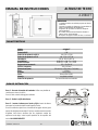
ALTAVOZ DE TECHO
CARACTERÍSTICAS
Paso 1 – Recorte el tamaño del cuadrado. Utilice una plantilla de
cartulina para hacer el orificio.
Pase el cable a través del agujero realizado.
Paso 2 – Retire la rejilla del altavoz.
Paso 3 – Inserte el altavoz en el techo y fíjelo. Inserte el altavoz
hasta que los bordes de bafle frontal toquen el techo.
Gire los tornillos de sujeción en el sentido de las agujas del reloj para
apretar las lengüetas de montaje. El primer cuarto de vuelta rotará las
lengüetas hacia fuera, mientras que las siguientes vueltas las
apretaran hacia abajo, sobre la parte posterior de la superficie del
techo. NO SOBREAPRIETE
Modelo A-266ACT
Altavoz 6”
Potencia RMS 6 W
Selección de potencia a 100 V 6 W, 3 W y 1’5 W
Selección de potencia a 70 V 3 W, 1’5 W y 0’75 W
Impedancia
1k7 Ω, 3k3 Ω y 6k7 Ω
Sensibilidad 90 dB SPL a 1 W, 1 m y 1 kHz
Presión acústica 99 dB SPL a 6 W, 1 m y 1 kHz
Respuesta en frecuencia 100 ~ 20.000 Hz
Orificio a empotrar 195 x 195 mm
Dimensiones (mm) 220 (ancho) x 220 (alto) x 73 (fondo)
Peso 1,11 kg
Acabado Plástico ABS
Color Blanco (RAL 9016)
Montaje Lengüetas rotativas
Selección de potencia Por terminales del transformador
GUÍA DE INSTALACIÓN

INSTRUCTION MANUAL
A-266ACT Version 1.0 1/1
A-266ACT
W
ARNING:
⋅ Installation by qualified personnel only.
⋅ Speakers must be wired in parallel and connected to
the correct line terminals of amplifier.
⋅ Ensure that all speakers have the same polarity with
respect to each other.
⋅ Do not select another tapings if the speaker is in use.
⋅ No naked flame sources, such as li
g
hted candles,
should be placed on the apparatus.
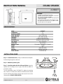
CEILING SPEAKER
SPECIFICATIONS
Step 1 – Cutout the hole size by using a cardboard cutout template.
Pull the wiring through the cutout hole.
Step 2 – Dismantle speaker’s grille.
Step 3 – Insert the speaker into the ceiling and tighten. Insert the
speaker into the ceiling as far as it goes, until the front baffle rim
touches the ceiling.
Turn the attachment screws CLOCKWISE to tighten the mounting
tabs. The first ¼ clockwise turn rotates the attachment tabs outward
and the remaining turns tighten the tabs down onto the back of the
ceiling surface. DO NOT OVERTIGHTEN.
Model A-266ACT
Loudspeaker 6”
Rated Power (RMS) 6 W
Power Taps 100 V 6 W , 3 W & 1’5 W
Power Taps 70 V 3 W, 1’5 W & 0’75 W
Impedance
1k7 Ω, 3k3 Ω & 6k7 Ω
Sensitivity 90 dB SPL a 1 W, 1 m y 1 kHz
Sound Pressure 99 dB SPL a 6 W, 1m y 1 kHz
Freq. Range 100 ~ 20.000 Hz
Cutout Size 195 x 195 mm
Dimension (mm) 220 (width) x 220 (height) x 73 (depth)
Weight 1,11 kg
Finish ABS
Colour White (RAL 9016)
Mounting Rotating mount tabs
Power selection Transformer taps
INSTALLATION GUIDE
-
 1
1
-
 2
2


Optimus A-266ACT Manual de usuario
- Categoría
- Altavoces
- Tipo
- Manual de usuario
en otros idiomas
- English: Optimus A-266ACT User manual
Artículos relacionados
-
Optimus A-252ATP Manual de usuario
-
-
-
-
-
-
-
-
-