4
1
2
3
5
6
6
3
4
5
1
2
Hardware Review
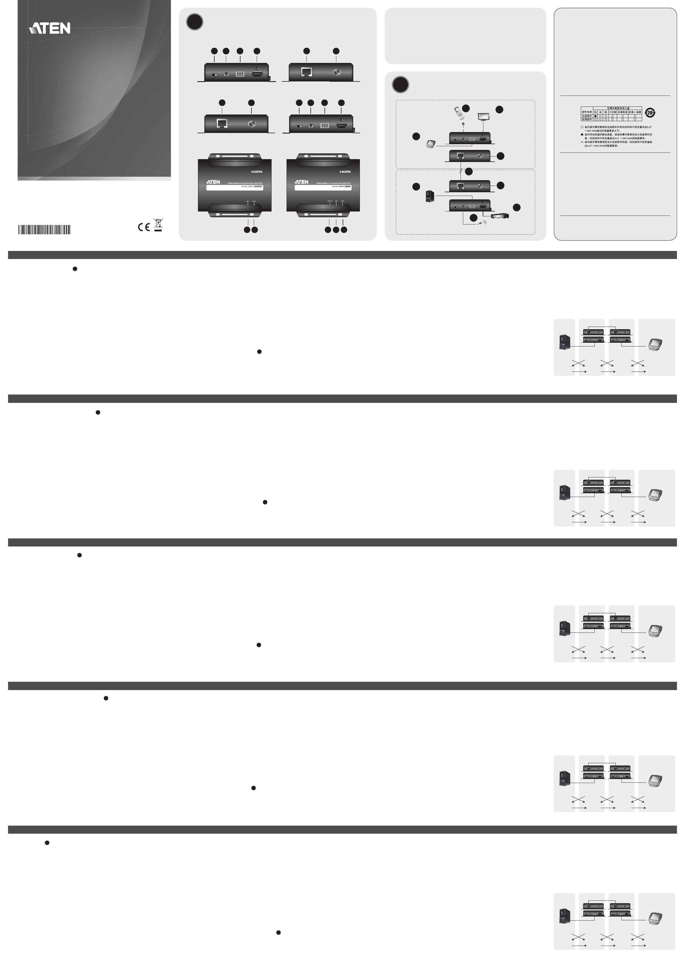
A
VE802T Front and Rear View
1. F/W upgrade switch
2. IR Port (Connect to IR Transmitter)
3. RS-232 Port
4. HDMI Input Port
5. HDBaseT Output Port
6. Power Jack
VE802R Top View
1. Link LED
2. Power LED
VE802R Front and Rear View
1. HDBaseT Input Port
2. Power Jack (Optional)
3. F/W upgrade switch
4. IR Port (Connect to IR Receiver)
Description de l’appareil
A
Vue avant et arrière VE802T
1. Commutateur de mise à niveau du microprogramme
2. Port infrarouge (à connecter à l’émetteur infrarouge)
3. Port RS-232
4. Port d’entrée HDMI
5. Port de sortie HDBaseT
6. Prise d’alimentation
Vue supérieure du VE802T
1. Voyant de liaison (Link)
2. Voyant d’alimentation
Vue avant et arrière VE802R
1. Port d’entrée HDBaseT
2. Prise d’alimentation (en option)
3. Commutateur de mise à niveau du microprogramme
4. Port infrarouge (à connecter au récepteur infrarouge)
Hardwareübersicht
A
VE802T – Vorder- und Rückseite
1. Schalter für Firmwareaktualisierung
2. Infrarotport (zum Anschluss an den Infrarotsender)
3. RS-232-Port
4. HDMI-Eingang
5. HDBaseT-Ausgang
6. Stromeingangsbuchse
VE802T - Oberseite
1. Verbindungsanzeige
2. LED-Betriebsanzeige
VE802R – Vorder- und Rückseite
1. HDBaseT-Eingangsport
2. Stromversorgung (optional)
3. Schalter für Firmwareaktualisierung
4. Infrarotport (zum Anschluss an den Infrarotempfänger)
Presentación del hardware
A
VE802T – Vistas frontal y posterior
1. Interruptor de actualización del fi rmware
2. Puerto de infrarrojos (conéctelo al transmisor de infrarrojos)
3. Puerto RS-232
4. Puerto de entrada HDMI
5. Puerto de salida HDBaseT
6. Entrada de alimentación
VE802T - Panel superior
1. Indicador de enlace (Link)
2. Indicador de alimentación
VE802R – Vistas frontal y posterior
1. Puerto de entrada HDBaseT
2. Entrada de alimentación (opcional)
3. Interruptor de actualización del fi rmware
4. Puerto de infrarrojos (conéctelo al receptor de infrarrojos)
Hardware
A
VE802T – vista anteriore e posteriore
1. Interruttore aggiornamento F/W
2. Porta infrarossi (da collegare al trasmettitore)
3. Porta RS-232
4. Porta d’ingresso HDMI
5. Porta d’uscita HDBaseT
6. Presa d’alimentazione
VE802T – vista superiore
1. LED di collegamento
2. LED d’alimentazione
VE802R – vista anteriore e posteriore
1. Porta d’ingresso HDBaseT
2. Presa d’alimentazione (opzionale)
3. Interruttore aggiornamento F/W
4. Porta infrarossi (da collegare al ricevitore)
5. RS-232 Port
6. HDMI Output Port
VE802R Top View
1. HDMI Out LED
2. Link LED
3. Power LED
Trouble Shooting
The Firmware upgrade port is reserved for tech support. If you would
like to do fi rmware upgrade yourself, please contact your dealer.
Hardware Installation
B
1. Connect the HDMI Input Port on the VE802T to the HDMI Output
Port on your video source device using HDMI cable.
2. Connect one end of the RJ-45 cable to the HDBaseT output port
on the transmitter. Then connect the other end of the RJ-45 cable
to the HDBaseT input port on the receiver.
5. Port RS-232
6. Port de sortie HDMI
Vue supérieure du VE802R
1. Voyant de sortie HDMI
2. Voyant de liaison (Link)
3. Voyant d’alimentation
Résolution des problèmes
Le port de mise à niveau du microprogramme est réservé à l’assistance
technique. Si vous souhaitez effectuer vous-même la mise à niveau du
microprogramme, veuillez contacter votre revendeur.
Installation du matériel
B
1. Connectez le port d’entrée HDMI du module VE802T au port de
sortie HDMI de votre périphérique vidéo source à l’aide d’un câble
HDMI.
5. RS-232-Port
6. HDMI-Ausgang
VE802R – Oberseite
1. LED-Anzeige des HDMI-Ausgangs
2. Verbindungsanzeige
3. LED-Betriebsanzeige
Problemlösung
Der Port zur Firmwareaktualisierung ist nur für Supportzwecke
vorgesehen. Falls Sie selbst eine Firmwareaktualisierung durchführen
möchten, wenden Sie sich an Ihren Fachhändler.
Hardware installieren
B
1. Verbinden Sie den HDMI-Eingang am VE802T mit dem HDMI-
Ausgang Ihrer Bildsignalquelle. Verwenden Sie dazu ein passendes
HDMI-Kabel.
5. Puerto RS-232
6. Puerto de salida HDMI
VE802R – Panel superior
1. Indicador LED de salida HDMI
2. Indicador de enlace (Link)
3. Indicador de alimentación
Solución de problemas
El puerto para actualizaciones del fi rmware está reservado para fi nes
de soporte técnico. Si desea actualizar el fi rmware por su cuenta,
póngase en contacto con su vendedor habitual.
Instalar el hardware
B
1. Conecte el puerto de entrada HDMI del VE802T al puerto de salida
HDMI de su dispositivo fuente de señal gráfi ca. Para ello, emplee
un cable HDMI.
5. Porta RS-232
6. Porta d’uscita HDMI
VE802R – vista superiore
1. LED uscita HDMI
2. LED di collegamento
3. LED d’alimentazione
Risoluzione dei problemi
La porta per l’aggiornamento del fi rmware è riservata all’assistenza
tecnica. Se si desidera effettuare in proprio l’aggiornamento, rivolgersi
al proprio rivenditore.
Installazione dell’hardware
B
1. Collegare la porta d’ingresso HDMI del VE802T alla porta di uscita
HDMI del dispositivo video sorgente tramite un cavo HDMI.
3. Connect the HDMI Output Port on the VE802R to the HDMI Input
Port on your video display device using HDMI Cable.
4. Plug the power adapter cable into the power jack on the VE802T.
5. (Optional)Plug the power adapter cable into the power jack on the
VE802R.
6. (Optional) Connect your compter or controller system to the
terminal block on the VE802 to serial commands
7. (Optional) Connect an IR Transmitter/Receiver to the IR port on the
VE802.
2. Connectez une extrémité du câble RJ-45 au port de sortie HDBaseT
de l’émetteur. Ensuite, connectez l’autre extrémité du câble RJ-45
au port d’entrée HDBaseT du récepteur.
3. Connectez le port de sortie HDMI du module VE802R au port
d’entrée HDMI de votre périphérique vidéo source à l’aide d’un
câble HDMI.
4. Branchez le câble de l’adaptateur secteur dans la prise
d’alimentation du module VE802T.
5. (Facultatif) Branchez le câble de l’adaptateur secteur dans la prise
d’alimentation du module VE802R.
6. (Facultatif) Connectez votre ordinateur ou votre système de
commande à la plaque à bornes située sur le VE802 pour réaliser
des commandes en série.
7. (Facultatif) Connectez un émetteur/récepteur infrarouge au port
infrarouge du VE802.
2. Verbinden Sie das eine Ende des RJ-45-Kabels mit dem HDBaseT-
Ausgang der Sendeeinheit. Verbinden Sie anschließend das
andere Ende des RJ-45-Kabels mit dem HDBaseT-Eingang der
Empfangseinheit.
3. Verbinden Sie den HDMI-Ausgang am VE802R mit dem HDMI-
Eingang Ihres Anzeigegerätes. Verwenden Sie dazu ein passendes
HDMI-Kabel.
4. Verbinden Sie das Kabel des Netzteils mit der Stromeingangsbuchse
am VE802T.
5. (Optional) Verbinden Sie das Kabel des Netzteils mit der
Stromeingangsbuchse am VE802R.
6. (Optional) Verbinden Sie Ihren Computer oder eine Steuereinheit
mit dem Anschlussblock des VE802, um das System über serielle
Befehle steuern zu können.
7. (Optional) Schließen Sie den Infrarot-Sender/-Empfänger an die
Infrarotbuchse des VE802 an.
2. Conecte un extremo del cable de RJ-45 al puerto de salida HDBaseT
del transmisor. Luego conecte el otro extremo del cable de RJ-45 al
puerto de entrada HDBaseT del receptor.
3. Conecte el puerto de salida HDMI del VE802R al puerto de entrada
HDMI de su dispositivo de visualización. Para ello, emplee un cable
HDMI.
4. Conecte el cable del adaptador de alimentación a la entrada de
alimentación del VE802T.
5. (Opcional) Conecte el cable del adaptador de alimentación a la
entrada de alimentación del VE802R.
6. (Opcional) Conecte su computadora o una controladora al bloque
de terminales del VE802 para poder controlar el sistema con
comandos serie
7. (Opcional) Conecte el transmisor/receptor de infrarrojos al puerto
para infrarrojos del VE802.
2. Collegare un’estremità del cavo RJ-45 alla porta di uscita HDBaseT
del trasmettitore. Collegare quindi l’altra estremità del cavo RJ-45
alla porta d’ingresso HDBaseT del ricevitore.
3. Collegare la porta d’uscita HDMI del VE802R alla porta d’ingresso
HDMI del dispositivo video sorgente tramite un cavo HDMI.
4. Inserire il cavo dell’alimentatore nella presa d’alimentazione del
VE802T.
5. (Opzionale) Inserire il cavo dell’alimentatore nella presa
d’alimentazione del VE802R.
6. (Opzionale) Collegare il computer o il controller alla morsettiera del
VE802 per eseguire i comandi seriali.
7. (Opzionale) Collegare il trasmettitore/ricevitore a infrarossi alla porta
infrarossi del VE802.
RS-232 Channel Transmission
You can connect RS-232 serial devices/peripherals to the VE802,
such as touchscreens and bar code scanners. The RS-232 signal
transmission fl ow is shown in the following example:
From a source device, the RS-232 signal is transmitted (Tx) to the
VE802T receiving (Rx) unit; the VE802R transmits (Tx) signals to the
display device (Rx).
Tx
Rx
Gnd
Tx
Rx
Gnd
Tx
Rx
Gnd
Tx
Rx
Gnd
Cat 5
Transmission par canal RS-232
Vous pouvez connecter des appareils/périphériques série RS-232 au
VE802, notamment des écrans tactiles et des lecteurs de codes-barres.
La transmission du signal RS-232 suit le parcours représenté dans
l’exemple ci-dessous :
À partir d’un périphérique source, le signal RS-232 est transmis (Tx) au
module récepteur VE802T (Rx) ; le module VE802R transmet (Tx) les
signaux au périphérique d’affi chage (Rx).
Tx
Rx
Gnd
Tx
Rx
Gnd
Tx
Rx
Gnd
Tx
Rx
Gnd
Cat 5
RS-232-Übertragung
Sie können serielle RS-232-Geräte wie z.B. Touchscreens oder
Strichcode-Scanner, an den VE802 anschließen. Das Flussdiagramm
der RS-232-Signalübertragung ist im folgenden Beispiel beschrieben:
Das RS-232-Signal wird von der Signalquelle gesendet (Tx) und von
der VE802T-Empfangseinheit empfangen (Rx); der VE802R sendet (Tx)
die Signale wiederum an das Anzeigegerät (Rx).
Tx
Rx
Gnd
Tx
Rx
Gnd
Tx
Rx
Gnd
Tx
Rx
Gnd
Cat 5
Transmisión por canal RS-232
Puede conectar dispositivos o periféricos serie RS-232 tales como
pantallas táctiles o lectores de códigos de barras al VE802. El fl ujo
de la transmisión de señales RS-232 se representa en el ejemplo
siguiente:
Del dispositivo fuente, la señal RS-232 se transmite (Tx) a la unidad
receptora (Rx) VE802T; el VE802R, a su vez, transmite (Tx) las señales
al dispositivo de visualización (Rx).
Tx
Rx
Gnd
Tx
Rx
Gnd
Tx
Rx
Gnd
Tx
Rx
Gnd
Cat 5
Trasmissione canale RS-232
È possibile collegare dispositivi/periferiche seriali RS-232 al VE802,
come per esempio touchscreen e lettori di codici a barre. Il fl usso della
trasmissione del segnale RS-232 è illustrato nel seguente esempio:
Il segnale RS-232 è trasmesso (Tx) da un dispositivo sorgente all’unità
ricevente VE802T (Rx), quindi il VE802R trasmette (Tx) i segnali al
dispositivo di visualizzazione (Rx).
Tx
Rx
Gnd
Tx
Rx
Gnd
Tx
Rx
Gnd
Tx
Rx
Gnd
Cat 5
B
Package Contents
VE802
1 VE802T/R HDMI
HDBaseT-Lite Extender
with POH
1 Power Adapter (VE802T)
1 IR Transmitter
1 IR Receiver
2 Terminal Blocks
1 User Instructions
VE802T Front and Rear View
VE802R Front and Rear View
VE802T and VE802R Top View
Hardware Installation
© Copyright 2015 ATEN
®
International Co., Ltd.
ATEN and the ATEN logo are trademarks of ATEN International Co., Ltd. All rights reserved. All
other trademarks are the property of their respective owners.
This product is RoHS compliant.
Part No. PAPE-1223-D40G Printing Date: 02/2015
HDMI HDBaseT-Lite Extender with POH
Quick Start Guide
VE802
VE802 HDMI HDBaseT-Lite Extender with POH Quick Start Guide
www.aten.com
Système d'extension HDBaseT-Lite HDMI VE802 avec alimentation par HDBaseT (POH) – Guide de démarrage rapide
www.aten.com
VE802 HDBaseT-Lite HDMI-Verlängerung mit PoH Kurzanleitung
www.aten.com
VE802 Alargador HDMI HDBaseT-Lite con PoH Guía rápida
www.aten.com
Estensore HDMI HDBaseT-Lite con POH VE802 - Guida rapida
www.aten.com
ATEN VanCryst
™
Important Notice
Considering environmental protection, ATEN does not provide a fully
printed user manual for this product. If the information contained in the
Quick Start Guide is not enough for you to confi gure and operate your
product, please visit our website www.aten.com, and download
the full user manual.
Online Registration
http://eservice.aten.com
Technical Phone Support
International:
886-2-86926959
North America:
1-888-999-ATEN Ext: 4988
United Kingdom:
44-8-4481-58923
All information, documentation, firmware, software utilities, and
specifi cations contained in this package are subject to change without
prior notification by the manufacturer. Please visit our website http://
www.aten.com/download/?cid=dds for the most up-to-date versions.
EMC Information
FEDERAL COMMUNICATIONS COMMISSION INTERFERENCE STATEMENT:
This equipment has been tested and found to comply with the limits for a Class A
digital device, pursuant to Part 15 of the FCC Rules. These limits are designed to provide
reasonable protection against harmful interference when the equipment is operated
in a commercial environment. This equipment generates, uses, and can radiate radio
frequency energy and, if not installed and used in accordance with the instruction
manual, may cause harmful interference to radio communications. Operation of this
equipment in a residential area is likely to cause harmful interference in which case the
user will be required to correct the interference at his own expense.
FCC Caution: Any changes or modifi cations not expressly approved by the party
responsible for compliance could void the user's authority to operate this equipment.
CE Warning: This is a class A product. In a domestic environment this product may cause
radio interference in which case the user may be required to take adequate measures.
Suggestion: Shielded twisted pair (STP) cables must be used with the unit to ensure
compliance with FCC & CE standards.
The following contains information that relates to China:
VE802T
1 VE802T HDMI HDBaseT-
Lite Transmitter with POH
1 Power Adapter
1 IR Transmitter
1 Terminal Block
1 User Instructions
VE802R
1 VE802R HDMI HDBaseT-
Lite Receiver with POH
1 Power Adapter
1 IR Receiver
1 Terminal Block
1 User Instructions
1
2
31
2
Serial Device
Remote Control of
HDMI Source
HDMI Source
Device
VE802R
VE802T
HDMI Display
RS-232 to
Serial Device
IR Transmitter
IR Receiver
1
2
3
5
6
6
7
7
4
PIN
CONFIGURATION
(Captive screw
connectors)
CONFIGURATION
DES BROCHES
(Connecteurs à vis
imperdable)
PIN-ZUORDNUNG
(Stecker mit
Rändelschrauben)
CONFIGURACIÓN
DE PATILLAS
(conector
con rosca de
seguridad)
CONFIGURAZIONE
DEI PIN
(connettori a vite
prigioniera)
Serial
Device
Périphérique
série
Serielles
Gerät
Dispositivo
serie
Dispositivo
seriale
A
Hardware Review
