LG DT30BTSG El manual del propietario
- Categoría
- Secadoras de ropa eléctricas
- Tipo
- El manual del propietario

5
MFL69702032
DWG.
No.
TRIG.
DR COMPLETED
도면 DR 완료
완료일 :
LG 전자 (주)
LG Electronics Inc.
UNIT SCALE
1
1
mm
REVIEWEDDESIGNED
RELATED DWG.
CHECKED APPROVEDMODELING
I
T
L
E
T
APPROVED
승인자
PREPARED
시방자
DATE
년/월/일
REF. NO.
시방 번호
REV. NO.
기호
REVISION DESCRIPTION
변경 사항
RELEASING THIS DRAWING
WITHOUT PERMISSION LG
Electronics SHOULD BE
ACCUSED ACCORDING TO THE
LAWS AND COMPANY RULES.
이 도면은 LG전자의 자산으로 불법
유출시 관계법과 회사규정에 의해 처벌됨.
PDF
ILLUSTRATOR
MANUAL,OWNER’S
1/1
<< 주기 >>
1. 재질, 인쇄방법, 인쇄도수, 외곽치수등은 작업표에 준한다.
2. 인쇄내용, 문자크기 및 형상, 선의 굵기 등은 설계에서 제시된 FILM에 준함.
3. 외곽치수는 절단후 치수임.
4. 양산전에 설계 한도를 득할 것.
5. 본 부품에 금지물질이 포함되지 않도록 하고,
상세 내용은 LG(63)-A-5501-34를 만족할 것.
<< NOTES >>
1. Material, printing and exterier size are refer to work tables.
2. Printing, text size and line are based on LG design film.
3. Exterier size on the drawing is cutting line.
4. Before product controlled by criteria sample.
5. The part should not contain prohibited substances(Pb,Cd,Hg,Cr+6,PBB,PBDE)
and details should comply with LG standard of LG(63)-A-5501-34.
가
<FRONT>
<BACK>
WORK
가
BRAND
LG
나
P/NO.
LG MODEL 명.
표지: 모조지 150g OFFSET 인쇄
내지: 모조지 80g OFFSET 인쇄
MATERIAL AND PRINTING DESCRIPTION
1 1
PRINTING DEGREE
EXTERIER INTERIER
영어
스페인어
LANGUAGE
108
PAGE
REMARK
SEC.
LAT
P/NO. 나
DT30BTSG
150150
210
32
MFL69702032
1
2
3
4
6
7
8
9
10
11
12
양 보 미 양 보 미 정 영 석
18.01.12
18.01.12 18.01.12
MFL69702032
TD(D)29 Wi-Fi LAT향
정영석양보미18/01/18EAGI100563
인쇄물심의회 지적사항 적용

ENGLISH ESPAÑOL
MFL69702032
www.lg.com
Copyright © 2018 LG Electronics Inc. All Rights Reserved.
OWNER’S MANUAL
DRYER
DT30BTSG
Please read this owner’s manual thoroughly before operating
and keep it handy for reference at all times.
MFL69702032_en_180118.indd 1 2018.1.18 1:41:53 PM

2
TABLE OF CONTENTS
TABLE OF CONTENTS
3
IMPORTANT SAFETY INSTRUCTIONS
4 BASIC SAFETY PRECAUTIONS
5 GROUNDING INSTRUCTIONS
5 SAFETY INSTRUCTIONS FOR
INSTALLATION
7 SAFETY INSTRUCTIONS FOR CONNECTING
ELECTRICITY
8
PRODUCT FEATURES
9
INTRODUCING YOUR DRYER
9 Parts and Accessories
9 Two-Way Reversible Door
10 Control Panel Features
11 Display
12
INSTALLATION INSTRUCTIONS
12 Preview Installation Order
13 Installation Location Requirements
13 Clearances
14 Leveling the Dryer
15 Reversing the Door
23 Installing the Side Vent Kit
24 Venting the Dryer
26 Connecting the Inlet Hose
27 Connecting Gas Dryers
29 Connecting Electric Dryers
34 Special Requirements for Manufactured or
Mobile Homes
34 Final Installation Check
35 Installation Test (Duct Check)
37
HOW TO USE
37 Operating the Dryer
38 Sorting Loads
38 Loading the Dryer
38 Check the Lint Filter Before Every Load
38 Using the Lid
39 Using the LG EasyLoad™
40 Cycle Guide
41 Cycle Settings and Options
41 Special Functions
42 Custom Program
43 Steam Functions
44 Steam Cycle Guide
45
SMART FUNCTIONS
45 Smart ThinQ Application
48 Smart Diagnosis™ Function
49
MAINTENANCE
49 Regular Cleaning
50
TROUBLESHOOTING
50 Before Calling for Service
53
SPECIFICATIONS
MFL69702032_en_180118.indd 2 2018.1.18 1:41:54 PM

3
ENGLISH
IMPORTANT SAFETY INSTRUCTIONS
READ ALL INSTRUCTIONS BEFORE USE
w
WARNING
For your safety, the information in this manual must be followed to minimize the risk of fire, explosion, or electric
shock, or to prevent property damage, injury to persons, or death.
Your safety and the safety of others is very important.
We have provided many important safety messages in this manual and on your appliance. Always read and obey all
safety messages.
This is the safety alert symbol.
This symbol alerts you to potential hazards that can kill or hurt you and others.
All safety messages will follow the safety alert symbol and either the word DANGER, WARNING, or CAUTION.
These words mean:
w
DANGER
You will be killed or seriously injured if you don’t immediately follow instructions.
w
WARNING
You can be killed or seriously injured if you don’t follow instructions.
w
CAUTION
You may be slightly injured or cause damage to the product if you do not follow instructions.
All safety messages will tell you what the potential hazard is, tell you how to reduce the chance of injury, and tell
you what can happen if the instructions are not followed.
• Do not install a clothes dryer with flexible plastic venting materials. If flexible metal (foil type) duct is
installed, it must be of a specific type identified by the appliance manufacturer as suitable for use with
clothes dryers. Flexible venting materials are known to collapse, be easily crushed, and trap lint. These
conditions will obstruct clothes dryer airflow and increase the risk of fire.
• Install the clothes dryer according to the manufacturer’s instructions and local codes.
• Save these instructions.
w
WARNING
FIRE OR EXPLOSION HAZARD
Failure to follow safety warnings exactly could result in serious injury, death or property damage.
- Do not store or use gasoline or other flammable vapors and liquids in the vicinity of this or any other appliance.
- WHAT TO DO IF YOU SMELL GAS
• Do not try to light any appliance.
• Do not touch any electrical switch; do not use any phone in your building.
• Clear the room, building or area of all occupants.
• Immediately call your gas supplier from a neighbor’s phone. Follow the gas supplier’s instructions.
• If you cannot reach your gas supplier, call the fire department.
- Installation and service must be performed by a qualified installer, service agency or the gas supplier.
w
IMPORTANT SAFETY INSTRUCTIONS
MFL69702032_en_180118.indd 3 2018.1.18 1:41:54 PM

4
IMPORTANT SAFETY INSTRUCTIONS
READ ALL INSTRUCTIONS BEFORE USE
w
WARNING
For your safety, the information in this manual must be followed to minimize the risk of fire, explosion, or electric
shock, or to prevent property damage, injury to persons, or death.
BASIC SAFETY PRECAUTIONS
w
WARNING
To reduce the risk of fire, electric shock, or injury to persons when using this appliance, follow basic precautions,
including the following:
• Read all instructions before using the dryer.
• Before use, the dryer must be properly installed as
described in this manual.
• Do not place items exposed to cooking oils in your
dryer. Items contaminated with cooking oils may
contribute to a chemical reaction that could cause a
load to catch fire.
• Do not dry articles that have been previously cleaned
in, washed in, soaked in, or spotted with gasoline, dry-
cleaning solvents, or other flammable or explosive
substances as they give off vapors that could ignite or
explode.
• Do not reach into the dryer if the drum or any other
part is moving.
• Do not repair or replace any part of the dryer
or attempt any servicing unless specifically
recommended in this owner’s manual or in published
user-repair instructions that you understand and have
the skills to carry out.
• Do not tamper with controls.
• Before the dryer is removed from service or discarded,
remove the door to the drying compartment.
• Do not allow children to play on or in the dryer. Close
supervision of children is necessary when the dryer is
used near children.
• This appliance is not intended for use by persons
(including children) with reduced physical, sensory
or mental capabilities, or lack of experience and
knowledge, unless they have been given supervision
or instruction concerning use of the appliance by a
person responsible for their safety.
• Children should be supervised to ensure that they do
not play with the appliance.
• Do not use fabric softeners or products to eliminate
static unless recommended by the manufacturer of
the fabric softener or product.
• Do not use heat to dry articles containing foam rubber
or similarly textured rubber-like materials.
• Keep area around the exhaust opening and adjacent
surrounding areas free from the accumulation of lint,
dust, and dirt.
• The interior of the dryer and exhaust vent should be
cleaned periodically by qualified service personnel.
• Do not install or store the dryer where it will be
exposed to the weather.
• Always check the inside of the dryer for foreign
objects.
• Clean lint screen before or after each load.
• Do not store plastic, paper, or clothing that may
burn or melt on top of the dryer during operation.
• Be careful when opening and closing the door. Fingers
and hands can get caught in the door and cause injury
if the door drops forward unexpectedly.
• Do not place heavy items on or lean against the top
of the door when it is open.
• Do not attempt to pull the hamper door open more
than 40 degrees.
• The dryer could tip forward, causing injury or damage.
• Do not place items on the top of the dryer.
• Certain internal parts are intentionally not grounded
and may present a risk of electric shock only during
servicing.
Service personnel - do not contact the following parts
while the appliance is energized: valve, motor, control
board, heater, generator.
w
WARNING
Never stop a tumble dryer before the end of the
drying cycle unless all items are quickly removed and
spread out so that the heat is dissipated.
• Exhaust air must not be discharged into a flue which
is used for exhausting fumes from appliances burning
gas or other fuels.
• The appliance must not be installed behind a lockable
door, a sliding door or a door with a hinge on the
opposite side to that of the tumble dryer.
* Items such as foam rubber (latex foam), shower caps,
waterproof textiles, rubber backed articles and clothes
or pillows fitted with foam rubber pads should not be
dried in the tumble dryer.
IMPORTANT SAFETY INSTRUCTIONS
MFL69702032_en_180118.indd 4 2018.1.18 1:41:54 PM

5
ENGLISH
IMPORTANT SAFETY INSTRUCTIONS
READ ALL INSTRUCTIONS BEFORE USE
w
WARNING
For your safety, the information in this manual must be followed to minimize the risk of fire, explosion, or electric
shock, or to prevent property damage, injury to persons, or death.
GROUNDING INSTRUCTIONS
w
WARNING
Improper connection of the equipment-grounding conductor can result in a risk of electric shock. Check with a
qualified electrician or service person if you are in doubt that the appliance is properly grounded.
SAFETY INSTRUCTIONS FOR INSTALLATION
w
WARNING
To reduce the risk of fire, electric shock, or injury to persons when using this appliance, follow basic precautions,
including the following:
• Properly ground dryer to conform with all
governing codes and ordinances. Follow details in
the installation instructions. Electric shock can result if
the dryer is not properly grounded.
• Before use, the dryer must be properly installed as
described in this manual. Electric shock can result if
the dryer is not properly grounded.
• Install and store the dryer where it will not be
exposed to temperatures below freezing or
exposed to the weather.
• All repairs and servicing must be performed
by an authorized servicer unless specifically
recommended in this owner’s manual. Use only
authorized factory parts. Failure to follow this
warning can cause serious injury, fire, electric shock, or
death.
• To reduce the risk of electric shock, do not install
the dryer in humid spaces. Failure to follow this
warning can cause serious injury, fire, electric shock, or
death.
• Connect to a properly rated, protected, and sized
power circuit to avoid electrical overload. Improper
power circuit can melt, creating electric shock and/or
fire hazard.
• Remove all packing items and dispose of all
shipping materials properly. Failure to do so can
result in death, explosion, fire, or burns.
• Place dryer at least 18 inches above the floor for
a garage installation. Failure to do so can result in
death, explosion, fire, or burns.
• Keep all packaging from children. Packaging
material can be dangerous for children. There is a risk
of suffocation.
• Do not install near another source of heat such as
a stove, cooking oven. Failure to do so can cause
deform, smoke and fire.
• Do not place candles, smoking materials, or other
flammables on top of the product. Dripping wax,
smoke, or fire can result.
• Remove all protective vinyl film from the product.
Failure to do so can cause product damage, smoke or
fire.
• Certain internal parts are intentionally not grounded
and may present a risk of electric shock only during
servicing.
Service personnel - do not contact the following parts
while the appliance is energized: valve, motor, control
board, heater, generator.
This appliance must be grounded. In the event of
malfunction or breakdown, grounding will reduce
the risk of electric shock by providing a path of least
resistance for electric current. This appliance must be
equipped with a cord having an equipment-grounding
conductor and a grounding plug. The plug must be
plugged into an appropriate outlet that is properly
installed and grounded in accordance with all local
codes and ordinances.
Do not modify the plug provided with the appliance. If
it will not fit the outlet, have a proper outlet installed by
a qualified electrician.
This appliance must be connected to a grounded metal,
permanent wiring system or an equipment-grounding
conductor must be run with the circuit conductors and
connected to the equipment-grounding terminal or
lead on the appliance.
Electric shock can result if the dryer is not properly
grounded.
IMPORTANT SAFETY INSTRUCTIONS
MFL69702032_en_180118.indd 5 2018.1.18 1:41:54 PM

6
IMPORTANT SAFETY INSTRUCTIONS
READ ALL INSTRUCTIONS BEFORE USE
w
WARNING
For your safety, the information in this manual must be followed to minimize the risk of fire, explosion, or electric
shock, or to prevent property damage, injury to persons, or death.
SAFETY INSTRUCTIONS FOR INSTALLATION
w
WARNING
To reduce the risk of injury to persons, follow all industry recommended safety procedures including the use of long
sleeved gloves and safety glasses. Failure to follow all of the safety warnings in this manual could result in property
damage, injury to persons, or death.
Exhaust/Ducting:
• Gas dryers MUST be exhausted to the outside.
Failure to follow these instructions can result in fire or
death.
• The dryer exhaust system must be exhausted
to the outside of the dwelling. If the dryer is not
exhausted outdoors, some fine lint and large
amounts of moisture will be expelled into the
laundry area. An accumulation of lint in any area of
the home can create a health and fire hazard.
• Use only rigid, semi-rigid, or flexible metal 4-inch
diameter ductwork inside the dryer cabinet or for
exhausting to the outside. Use of plastic or other
combustible ductwork can cause a fire. Punctured
ductwork can cause a fire if it collapses or becomes
otherwise restricted in use or during installation.
• Ductwork is not provided with the dryer, and you
should obtain the necessary ductwork locally. The
end cap should have hinged dampers to prevent
backdraft when the dryer is not in use. Failure to
follow these instructions can result in fire or death.
• The exhaust duct must be 4 inches (10.2 cm) in
diameter with no obstructions. The exhaust duct
should be kept as short as possible. Make sure
to clean any old ducts before installing your new
dryer. Failure to follow these instructions can result in
fire or death.
* Fabric softeners, or similar products, should be used as
specified by the fabric softener instructions.
* Remove all objects from pockets such as lighters and
matches.
• Rigid, semi-rigid, or flexible metal ducting is
recommended for use between the dryer and the
wall. All non-rigid metal transition duct must be
UL-listed. Use of other materials for transition
ducting could affect drying time. Failure to follow
these instructions can result in fire or death.
• DO NOT use sheet metal screws or other fasteners
which extend into the duct that could catch lint and
reduce the efficiency of the exhaust system. Secure
all joints with duct tape. For complete details, follow
the Installation Instructions. Failure to follow these
instructions can result in fire or death.
w
WARNING
Fire Hazard
Failure to follow safety warnings exactly could result
in serious injury, death or property damage.
Do not install a booster fan in the exhaust duct.
Install all clothes dryers in accordance with the
installation instructions of the manufacturer of the
dryer.
w
WARNING
Never stop a tumble dryer before the end of the
drying cycle unless all items are quickly removed and
spread out so that the heat is dissipated.
a) For appliances with ventilation openings in the
base, that a carpet must not obstruct the openings.
b) Exhaust air must not be discharged into a flue
which is used for exhausting fumes from appliances
burning gas or other fuels.
IMPORTANT SAFETY INSTRUCTIONS
MFL69702032_en_180118.indd 6 2018.1.18 1:41:55 PM

7
ENGLISH
IMPORTANT SAFETY INSTRUCTIONS
READ ALL INSTRUCTIONS BEFORE USE
w
WARNING
For your safety, the information in this manual must be followed to minimize the risk of fire, explosion, or electric
shock, or to prevent property damage, injury to persons, or death.
SAFETY INSTRUCTIONS FOR CONNECTING ELECTRICITY
w
WARNING
To reduce the risk of fire, electric shock, or injury to persons when using this appliance, follow basic precautions,
including the following:
• Do not, under any circumstances, cut or remove
the ground prong from the power cord. To prevent
injury to persons or damage to the dryer, the electrical
power cord must be plugged into a properly grounded
outlet.
• For personal safety, this dryer must be properly
grounded. Failure to do so can result in electric shock
or injury.
• Refer to the installation instructions in this manual
for specific electrical requirements for your model.
Failure to follow these instructions can create an
electric shock hazard and/or a fire hazard.
• This dryer must be plugged into a properly
grounded outlet. Electric shock can result if the
dryer is not properly grounded. Have the wall
outlet and circuit checked by a qualified electrician
to make sure the outlet is properly grounded.
Failure to follow these instructions can create an
electric shock hazard and/or a fire hazard.
• If the supply cord is damaged, it must be replaced
by the manufacturer, its service agent or similarly
qualified persons in order to avoid a hazard.
• The dryer should always be plugged into its own
individual electrical outlet which has a voltage
rating that matches the rating plate. This provides
sparkling performance and also prevents overloading
house wiring circuits which could cause a fire hazard
from overheated wires.
• Never unplug your dryer by pulling on the power
cord. Always grip plug firmly and pull straight out
from the outlet. The power cord can be damaged,
resulting in a risk of fire and electric shock.
• Repair or replace immediately all power cords that
have become frayed or otherwise damaged. Do not
use a cord that shows cracks or abrasion damage
along its length or at either end. The power cord can
melt, creating an electric shock and/or fire hazard.
• When installing or moving the dryer, be careful not
to pinch, crush, or damage the power cord. This will
prevent injury and prevent damage to the dryer from
fire and electric shock.
SAVE THESE INSTRUCTIONS
IMPORTANT SAFETY INSTRUCTIONS
MFL69702032_en_180118.indd 7 2018.1.18 1:41:55 PM

8
PRODUCT FEATURES
EASY-TO-USE CONTROL PANEL
Rotate the cycle selector knob to select the desired dry cycle. Add cycle options or adjust settings with the touch
of a button.
TWO-WAY EASY-ACCESS REVERSIBLE DOOR
The LG EasyLoad™ can be tilted open from the top, hamper-style, allowing you to easily load the dryer without
items falling on the floor. The door still swings open to provide easy access for unloading or loading of bulkier
items. The door hinge can be reversed to adjust for installation location.
STEAM FUNCTIONS
LG’s steam technology allows you to inject fabrics with a swirling jet of hot steam to refresh clothes, reduce static.
Simply select the Steam Fresh™ cycle, you can add a Steam option to selected cycles.
Flow Sense™ DUCT BLOCKAGE SENSING SYSTEM INDICATOR
The Flow Sense™ duct blockage sensing system detects and alerts you to restrictions in the installed household
ductwork that reduce exhaust airflow through the dryer. If you see the alert: Clean or repair the ducts to remove
the restrictions. Keep your ducts clean to help increase efficiency and reduce long drying times caused by blocked
ducts.
Smart Diagnosis™
Should you experience any technical difficulty with your washing machine, it has the capability of transmitting
data by phone to the Customer Information Center. The call center agent records the data transmitted from your
machine and uses it to analyze the issue, providing a fast and effective diagnosis.
Smart ThinQ™
Download the new LG smart phone app to set options, self-diagnose and troubleshoot problems with the appliance,
and other useful features. This function uses Wi-Fi.
PRODUCT FEATURES
MFL69702032_en_180118.indd 8 2018.1.18 1:41:55 PM

9
ENGLISH
INTRODUCING YOUR DRYER
Parts and Accessories
Parts
Control
panel
Leveling
feet
Reversible
door
Lint filter
Terminal
block
access panel
(Electric
models)
Gas
connection
location
(Gas models)
Power cord
location
(Gas
models)
Exhaust
duct
outlet
NOTE
• Visit www.lg.com to purchase accessories.
• Contact LG Customer Service if any accessories are missing.
• For your safety and for extended product life, use only authorized components. The manufacturer is not
responsible for product malfunction or accidents caused by the use of separately purchased unauthorized
components or parts.
• The images in this owner’s manual may be different from the actual components and accessories, which are
subject to change by the manufacturer without prior notice for product improvement purposes.
INTRODUCING YOUR DRYER
Two-Way Reversible Door
Release
Hamper door
The LG EasyLoad™ feature allows you to open the dryer
door from the top, hamper-style, when loading the
dryer to help guide clothes into the drum and prevent
them from falling onto the floor. When unloading the
dryer or loading bulkier items, use the swing door for
easy access to the drum. For more details on using the
door, see page 37. For information on reversing the
door swing, see page 15.
Swing door
Accessories
Side vent kit
(sold separately)
Kit No. 383EEL9001B
Drying rack
(AHB73109001)
Included accessories
Optional accessories
HoseY connector Safety Tether Kit
Safety Tether Kit
This optional kit helps prevent the dryer tipping if children climb on the door or if someone should fall onto the door. It is
recommended that you install this kit, depending on your situation, but it is not required. Follow the customer installation
instructions included with the kit to properly install the kit. If you do not install the kit, store it out of reach of children.
MFL69702032_en_180118.indd 9 2018.1.18 1:42:3 PM

10
Control Panel Features
Following are instructions for starting and using your new dryer. Please refer to specific sections of this manual for
more detailed information.
w
WARNING
To reduce the risk of fire, electric shock, or injury to persons, read this entire manual, including the Important Safety
Instructions, before operating this dryer.
Button Description
Power On/Off Button
y
- Press to turn the dryer On. Press again to turn the dryer Off.
NOTE : Pressing the On/Off button during a cycle cancels that cycle and any
load settings are lost.
Cycle Selector Knob
y
- Turn this knob to select the desired cycle. Once the desired cycle has been
selected, the standard presets are shown in the display. On Manual Dry cycles,
these settings can be adjusted using the cycle modifier buttons any time
before starting the cycle.
Start/Pause Button
y
-
Press this button more than 0.4 seconds hold to start the selected cycle. If the dryer
is running, use this button to pause the cycle without losing the current settings.
NOTE : If you do not press the Start/Pause button to resume a cycle within four
minutes, the dryer turns off automatically.
More Time/Less Time Buttons
y
- To adjust the drying time, use these buttons with Manual Dry, Time Dry, and
Steam Fresh™ cycles, as well as the Reduce Static and TurboSteam options.
Press the More Time button to increase the selected manual cycle time by a
minute; press Less Time to decrease the cycle time by a minute.
Cycle Modifier Buttons
y
- Use these buttons to select the desired cycle settings for the selected cycle.
The current settings are shown in the display. Press the button for that option
to view and select other settings.
Option Buttons
y
- The Option buttons allow you to select additional cycle options. Certain
buttons also allow you to activate special functions by pressing and holding
the button for three seconds.
Steam Functions
y
-
LG’s steam technology allows you to inject fabrics with a swirling jet of hot steam
to refresh or sanitize clothes, or reduce static. Simply select the Steam Fresh™ or
Steam Sanitary™ cycle. Or you can add a steam option to selected cycles.
Operation
INTRODUCING YOUR DRYER
MFL69702032_en_180118.indd 10 2018.1.18 1:42:6 PM

11
ENGLISH
Display
The display shows the settings, estimated time remaining, options, and status messages for your dryer. When the
dryer is turned on, the light in the display illuminates.
w
WARNING
To reduce the risk of fire, electric shock, or injury to persons, read this entire manual, including the Important Safety
Instructions, before operating this dryer.
Button Description
Estimated Time Remaining
y
- When the Start/Pause button is pressed, the dryer displays the estimated
(Sensor Dry) or set time (Time Dry) remaining, and begins tumbling.
NOTE : The cycle time on Sensor Dry cycles may fluctuate as the dryer
recalculates drying time for optimal results
Cycle Completion Indicator with Check Filter Reminder
y
- This portion of the display shows which stage of the drying cycle is currently
underway (Clean Filter, Dry, or cool.).
Control Lock Indicator
y
- When Control Lock is set, the Control Lock indicator appears and all buttons
are disabled except the Power button. This prevents children from changing
settings while the dryer is operating
Clean Filter Reminder
y
- The display shows Clean Filter when the dryer is turned on as a reminder to
check the filter. It turns off when the Start/Pause button is pressed.
WI-FI Indicator
y
- When the appliance is connected to the internet through a home Wi-Fi
network, this indicator appears.
Flow Sense™ Duct Blockage Sensing System Indicator
y
- The Flow Sense™ duct blockage sensing system detects and alerts you to
blockages in the ductwork that reduce exhaust flow from the dryer. This
improves operating efficiency and helps minimize service calls, saving you
money.
INTRODUCING YOUR DRYER
MFL69702032_en_180118.indd 11 2018.1.18 1:42:7 PM

12
INSTALLATION INSTRUCTIONS
Preview Installation Order
Checking and choosing the
proper location
Leveling the dryer
Connecting electric dryers
Venting the dryer
Plugging in the power cord
and grounding
Connecting gas dryers
Test run
Installation test
Press and hold
120V~ 240V~
INSTALLATION INSTRUCTIONS
MFL69702032_en_180118.indd 12 2018.1.18 1:42:9 PM

13
ENGLISH
Installation Location Requirements
w
WARNING
Read all installation instructions completely before installing and operating your dryer! It is important that
you review this entire manual before installing and using your dryer. Detailed instructions concerning electrical
connections, gas connections, and exhaust requirements are provided on the following pages.
Do not operate your dryer at temperatures below 45°F (7°C). At lower temperatures, the dryer might not shut off
at the end of an automatic cycle. This can result in longer drying times. The dryer must not be installed or stored in
an area where it will be exposed to water and/or weather. Check code requirements. Some codes limit, or do not
permit, installation of the dryer in garages, closets, mobile homes or sleeping quarters. Contact your local building
inspector.
Clearances
Installation Spacing For Recessed Area Or Closet Installation
The following spacing dimensions are recommended for this dryer. This dryer has been tested for clearances of
1 inch(2.5 cm) on the sides and rear. Recommended spacing should be considered for the following reasons:
• A location that allows for proper exhaust installation. A
gas dryer must be exhausted to the outdoors.
See Venting the dryer.
• A grounded electrical outlet located within 2 ft.
(61 cm) of either side of the dryer. See Connecting
electric dryers.
• A sturdy floor to support the total dryer weight of 200
lbs (90.7 kg). The combined weight of a companion
appliance should also be considered.
• No other fuel-burning appliance can be installed in the
same closet as a dryer.
• Additional spacing should be considered for ease of
installation and servicing.
• Additional clearances might be required for wall, door
and floor moldings.
• Additional spacing should be considered on all sides
of the dryer to reduce noise transfer.
For closet installation, with a door, minimum
ventilation openings in the top and bottom of the
door are required. Louvered doors with equivalent
ventilation openings are acceptable.
• Companion appliance spacing should also be
considered.
NOTE
• Floor must be level, with a maximum slope of 1 inch (2.5 cm) under entire dryer. Clothes may not tumble
properly, and automatic sensor cycles may not operate correctly if the dryer is not level.
• For a garage installation, you will need to place the dryer at least 18 inches (46 cm) above the floor. If using a
pedestal, you will need 18 inches (46 cm) to the bottom of the dryer.
NOTE
There should be at least a little space around the dryer (or any other appliance) to eliminate the transfer of
vibration from one to the other. An appliance that vibrates too much can make noise or shift against another
appliance, causing paint damage and additional noise.
24 in.
2*
(155 cm
2
)
18" min.*
(45,7 cm)
1"*
(2,5 cm)
30"
(76,1 cm)
30"
(76,1 cm)
5"**
(12,7 cm)
48 in.
2*
(310 cm
2
)
14" max.*
(35,6 cm)
3"
*
(7,6 cm)
3"
*
(7,6 cm)
1"
(2,5 cm)
27"
(68,6 cm)
1"
(2,5 cm)
1"*
(2,5 cm)
5"**
(12,7 cm)
14" max.*
(35,6 cm)
18" min.*
(45,7 cm)
0"
(0 cm)
39"
(99,1 cm)
1"
(2,5 cm)
27"
(68,6 cm)
1"
(2,5 cm)
30"
(76,1 cm)
5"**
(12,7 cm)
1"**
(2,5 cm)
1"
(2,5 cm)
1"
(2,5 cm)
27"
(68,6 cm)
9"**
(22,9 cm)
7"* (17,8 cm)
7"* (17,8 cm)
1"* (2,5 cm)
5
"**
(14 cm)
1/2
77
1/2
"
(196,8 cm)
3"* (7,6 cm)
6"*(15,2 cm)
3"* (7,6 cm)
27"
(68,6 cm)
1"
(2,5 cm)
1"
(2,5 cm)
24 in.
2*
(155 cm
2
)
48 in.
2*
(310 cm
2
)
Requisitos de ventilación
de la puerta del armario
(7,6 cm)
(7,6 cm)
31
(79.5 cm)
7"* (17.8 cm)
7"* (17.8 cm)
5"*
(12.7 cm)
1"*
(2.5 cm)
29"
(74.0 cm)
1"
(2.5 cm)
1"
(2.5 cm)
5
"
**
(12.7 cm)
14
"
max.*
(35.6
cm)
54
(138 cm)
31 29
"
(79.5 cm)
23
"
(58.5 cm)
2
⁄4
"
2
⁄4
"
52
(134 cm)
Closet Door Vent
Requirements
(7.6 cm)
(7.6 cm)
(2.5 cm) (2.5 cm)(74.0 cm)
3
⁄4
"
2
⁄4
"
31
(79,5 cm)
7"* (17,8 cm)
7"* (17,8 cm)
5"*
(12,7 cm)
1"*
(2,5 cm)
29"
(74,0 cm)
1"
(2,5 cm)
1"
(2,5 cm)
2
⁄4
"
13
2
⁄4
"
(35.2 cm)
5
"
**
(12,7 cm)
14
"
max.*
(35,6
cm)
54
(138 cm)
31 29
"
(79,5 cm)
23
"
(58,5 cm)
2
⁄4
"
2
⁄4
"
52
(134 cm)
(2,5 cm) (2,5 cm)(74,0 cm)
3
⁄4
"
13
2
⁄4
"
(35,2 cm)
45
1
⁄8
"
(114.6 cm)
45
1
⁄8
"
(114,6 cm)
INSTALLATION INSTRUCTIONS
MFL69702032_en_180118.indd 13 2018.1.18 1:42:11 PM

14
Clearances (cont.)
Recommended Installation Spacing For Cabinet Installation
• For cabinet installation with a door, minimum ventilation openings in the top of the cabinet are required.
*Required spacing
**For side or bottom venting,
2 inches (5.1 cm) clearance is allowed.
Leveling the Dryer
w
WARNING
• To reduce the risk of injury to persons, adhere to all
industry recommended safety procedures including
the use of long-sleeved gloves and safety glasses.
Failure to follow this warning can cause serious injury
or death.
• The appliances are heavy. Two or more people are
required when installing the dryer. Failure to follow
this warning can cause serious injury or death.
To ensure that the dryer provides optimal drying
performance, it must be level. To minimize vibration,
noise, and unwanted movement, the floor must be a
perfectly level, solid surface.
1. Position the dryer in the final location. Place a level
across the top of the dryer.
• All four leveling feet must rest solidly on the floor.
Gently push on the top corners of the dryer to make
sure that the dryer does not rock from corner to corner.
If you are installing the dryer on the optional pedestal,
you must use the leveling feet on the pedestal to
level the dryer. The dryer leveling feet should be fully
retracted.
2. Use an adjustable wrench to turn the leveling feet.
Turn clockwise to raise the dryer or counterclockwise
to lower it. Raise or lower the leveling feet until dryer
is level from side to side and front to back.
Make sure that all four leveling feet are in firm contact
with the floor.
Level
Leveling Feet
NOTE
Adjust the leveling feet only as far as necessary to
level the dryer. Extending the leveling feet more than
necessary can cause the dryer to vibrate.
24 in.
2*
(155 cm
2
)
18" min.*
(45,7 cm)
1"*
(2,5 cm)
30"
(76,1 cm)
30"
(76,1 cm)
5"**
(12,7 cm)
48 in.
2*
(310 cm
2
)
14" max.*
(35,6 cm)
3"
*
(7,6 cm)
3"
*
(7,6 cm)
1"
(2,5 cm)
27"
(68,6 cm)
1"
(2,5 cm)
1"*
(2,5 cm)
5"**
(12,7 cm)
14" max.*
(35,6 cm)
18" min.*
(45,7 cm)
0"
(0 cm)
39"
(99,1 cm)
1"
(2,5 cm)
27"
(68,6 cm)
1"
(2,5 cm)
30"
(76,1 cm)
5"**
(12,7 cm)
1"**
(2,5 cm)
1"
(2,5 cm)
1"
(2,5 cm)
27"
(68,6 cm)
9"**
(22,9 cm)
7"* (17,8 cm)
7"* (17,8 cm)
1"* (2,5 cm)
5
"**
(14 cm)
1/2
77
1/2
"
(196,8 cm)
3"* (7,6 cm)
6"*(15,2 cm)
3"* (7,6 cm)
27"
(68,6 cm)
1"
(2,5 cm)
1"
(2,5 cm)
24 in.
2*
(155 cm
2
)
48 in.
2*
(310 cm
2
)
Requisitos de ventilación
de la puerta del armario
(7,6 cm)
(7,6 cm)
31
(79.5 cm)
7"* (17.8 cm)
7"* (17.8 cm)
5"*
(12.7 cm)
1"*
(2.5 cm)
29"
(74.0 cm)
1"
(2.5 cm)
1"
(2.5 cm)
5
"
**
(12.7 cm)
14
"
max.*
(35.6
cm)
54
(138 cm)
31 29
"
(79.5 cm)
23
"
(58.5 cm)
2
⁄4
"
2
⁄4
"
52
(134 cm)
Closet Door Vent
Requirements
(7.6 cm)
(7.6 cm)
(2.5 cm) (2.5 cm)(74.0 cm)
3
⁄4
"
2
⁄4
"
31
(79,5 cm)
7"* (17,8 cm)
7"* (17,8 cm)
5"*
(12,7 cm)
1"*
(2,5 cm)
29"
(74,0 cm)
1"
(2,5 cm)
1"
(2,5 cm)
2
⁄4
"
13
2
⁄4
"
(35.2 cm)
5
"
**
(12,7 cm)
14
"
max.*
(35,6
cm)
54
(138 cm)
31 29
"
(79,5 cm)
23
"
(58,5 cm)
2
⁄4
"
2
⁄
4
"
52
(134 cm)
(2,5 cm) (2,5 cm)(74,0 cm)
3
⁄4
"
13
2
⁄4
"
(35,2 cm)
45
1
⁄8
"
(114.6 cm)
45
1
⁄8
"
(114,6 cm)
INSTALLATION INSTRUCTIONS
MFL69702032_en_180118.indd 14 2018.1.18 1:42:13 PM

15
ENGLISH
INSTALLATION INSTRUCTIONS
Before you Begin
NOTE
Service calls to reverse the door are not covered
under the product warranty.
• The door reversal process for the two-way door is more
complex than for a conventional dryer door. Read
through these instructions in their entirety before
beginning the process, in order to gauge whether to
have the procedure done by a professional installer or
service person.
• A support video is also provided at http://www.
lg.com/us/support/videos/video-tutorials-view, How
to Reverse the Door – LG EasyLoad™ Dryer.
Tools Required
• Phillips screwdriver
• Large flat blade screwdriver (recommended for hinge
screws if they are tight or your Phillips screwdriver is
worn)
• Small flat blade screwdriver (for lifting out parts)
w
WARNING
THE DRYER DOOR IS VERY LARGE AND HEAVY. Failure to
follow the instructions below may result in damage to
the dryer, property damage or personal injury.
• To avoid damage to the dryer or the door, support the
door with a stool or box that fits under the door, or
have an assistant support the weight of the door.
• Avoid dropping the door to avoid damage to the door
or the floor.
• Unplug the dryer or turn off power at the main circuit
breaker before beginning door reversal.
Door Reversal Instructions
NOTE
The instructions here are for changing the door swing
from a right to a left side hinge. If the door has been
reversed, and it is necessary to change it back, use
care when following these instructions. Some of
the illustrations and the left/right references will be
reversed, and you will need to read the instructions
carefully.
w
WARNING
Be sure to support the weight of the door before
removing the hinge screws.
Swing door
1. Open the door from the side so that the hinge
screws are accessible.
2. Remove the four hinge screws.
While supporting the door, remove the four hinge
screws, two from each hinge. Set the door aside face
down on a protected surface to prevent damage to
the door or the work surface.
3. Reverse the components on the cabinet.
hinge
hinge
cover
latch hole
cover
latch
mechanism
hinge
hinge
cover
a. Use a Phillips screwdriver to remove the two screws
and the latch mechanism on the front panel of the
cabinet.
b. Remove the latch hole cover by gently prying it
up with a flat blade screwdriver, being careful not
to scratch the paint. Install the latch hole cover on
the opposite side, where the latch mechanism was
removed. Install the latch mechanism in the position
from which you removed the latch hole cover, using
the two screws removed in step a.
c. Remove the hinge cover by gently prying it up with
a flat blade screwdriver, being careful not to scratch
the paint. Rotate the hinge cover 180 degrees and
install it on the opposite side, where the hinge was
attached.
Reversing the Door
MFL69702032_en_180118.indd 15 2018.1.18 1:42:15 PM

16
INSTALLATION INSTRUCTIONS
4. With the door on a protected surface, remove all
screws on each side of the door and lift off the inner
door frame using a flat blade screwdriver.
Remove the latch hook and blank and install them on
the opposite side.
Inner door
frame
Blank Latch hook
5. Remove the 4 screws securing the hinges to the door
frame. Remove the two plastic cover caps. Reinstall
the hinges and cover caps on the opposite sides from
which they were removed.
Hinge
assembly
Cover cap
6. With the hinges and cover caps in the new locations,
remount the inner door frame onto the outer door
frame with the screws removed in step 4 above.
w
WARNING
Be sure to support the weight of the door before
installing the hinge screws.
7. Reinstall the door.
While supporting the door, install the four hinge
screws removed in step 2. Test the swing of the
door to make sure the hinges and latch are properly
aligned and that the door opens, closes and latches
properly in both directions.
Swing
Door
Easy load door (on some models)
w
WARNING
Be sure to support the weight of the door before
installing the hinge screws.
ON THE CABINET :
1. Open the door from the side so that the hinge
screws are accessible.
Two large
screws
Two small
screws
2. Remove the four hinge screws
While supporting the door, remove the four hinge
screws, two from each hinge. Set the door aside face
down on a protected surface to prevent damage to
the door or the work surface.
MFL69702032_en_180118.indd 16 2018.1.18 1:42:17 PM

17
ENGLISH
INSTALLATION INSTRUCTIONS
3. Reverse the components on the cabinet.
Upper
hinge
Hinge
cover
Latch hole
cover
latch
mechanism
Hinge
bracket
Hinge
a. Use a Phillips screwdriver to remove the two screws
and the latch mechanism on the front panel of the
cabinet.
b. Remove the latch hole cover by gently prying it
up with a flat blade screwdriver, being careful not
to scratch the paint. Install the latch hole cover on
the opposite side, where the latch mechanism was
removed. Install the latch mechanism in the position
from which you removed the latch hole cover, using
the two screws removed in step a.
c. Remove the hinge cover by gently prying it up with
a flat blade screwdriver, being careful not to scratch
the paint. Rotate the hinge cover 180 degrees and
install it on the opposite side, where the upper hinge
was attached.
d. Reverse the hinge and the hinge bracket at the
bottom of the cabinet. Remove the two screws from
the hinge bracket at the bottom right and remove
the hinge bracket. Remove the lower of the two
screws behind the hinge bracket. Do NOT remove
the upper screw behind the hinge bracket. Set the
parts aside.
w
CAUTION
Do NOT remove any of the eight screws on the face of
the cabinet (marked below). Doing so could result in
damage to the dryer and the need for a service call to
repair the dryer.
e. Remove the three screws on the hinge at the
bottom left. Remove the hinge and reinstall it on the
right side. The top screw will occupy the hole where
you removed the screw behind the hinge bracket in
step d.
f. Install the hinge bracket removed in step d on the
bottom left side, first installing one screw behind the
hinge bracket.
hinge
cover
latch
mechanism
latch hole
cover
hinge
hinge
bracket
Cabinet Reversal complete
ON THE DOOR:
4. Lift off the door cover.
With the door laid inside facing up on a protected
surface, remove the twelve screws on the inside of
the door. Carefully lift off the door cover with the help
of a small flat blade screwdriver inserted in the upper
corner (circled below).
w
WARNING
The edges of the door cover may be sharp. Take care
when handling, or wear gloves to avoid injury.
Hole
plug
Twelve screws
Side
Interlock
button
MFL69702032_en_180118.indd 17 2018.1.18 1:42:20 PM

18
5. Switch the door strike and the blank cover.
Remove the two screws on the door cover that secure
the door strike.
Switch the door strike and the blank cover, installing
them on the opposite sides from which they were
removed.
Short
screws
Long
screw
Blank cover Door strike
Raise
Pull
Remove blank cover
Gently pry out the hole plug on the side of the door
cover and install it in the hole on the opposite side.
Hole
plug
Set the door cover aside.
INSTALLATION INSTRUCTIONS
MFL69702032_en_180118.indd 18 2018.1.18 1:42:21 PM

19
ENGLISH
6. Reverse the components inside the door.
You will now be removing and reversing various components inside the door. See below for a detailed diagram
and identification of the inner structure and parts of the door. (The diagram shows the “before view” of the door,
with the default set-up for a right side hinge swing. After following these instructions, your door should be a
mirror image of the illustration.)
Top interlock buttons
Upper
hinge
assembly
Upper
hinge filter
Lower
hinge filler
Lower hinge
bracket
Upper
hinge
pivot
Lower
hinge
assembly
Glass
Inner lock rods
Top lock rod
Side lock rod
Side Interlock button
Bumpers
Interlock buttons
Inner lock rods
Upper hinge assembly
Side lock rod
Hole plug
Upper hinge filler
Low hinge filler
Lower hinge bracket
Upper hinge pivot
Top lock rod
Lower hinge assembly
INSTALLATION INSTRUCTIONS
MFL69702032_en_180118.indd 19 2018.1.18 1:42:25 PM

20
INSTALLATION INSTRUCTIONS
7. Lift out the gray interlock button in the side of the
door.
Make sure to remove the spring with the interlock
button and to keep the two together. Set the interlock
button aside. Do not confuse these with the interlock
buttons from the top of the outer door.
8. Remove the side lock rod.
Remove the side lock rod from the lower hinge
bracket by lifting the top end of the rod and sliding it
toward the top of the door. The spring should remain
attached to the lock rod. Set the lock rod aside.
Spring
9. Remove the top lock rod.
a. Slide the lock rod to the right to remove it from the
hinge assembly on the left side.
b. While sliding the lock rod right, lift the right end up
and out of the guides.
NOTE
Do not remove the two inner lock rods and two
interlock buttons (see page 17) located underneath
the top lock rod. They do NOT need to be reversed.
10. Remove the upper hinge pivot.
Once the top lock rod has been removed, the
hinge pivot can easily be removed from the hinge
assembly on the upper left and set aside.
Upper
hinge
pivot
Upper hinge
assembly
11. Reverse the upper hinge assembly and hinge
filler.
Lift out the upper hinge filler (on the right) and set
it aside. Carefully lift the upper hinge assembly (on
the left) out of the outer door frame, using a small
flat blade screwdriver if necessary. Rotate the hinge
assembly 180 degrees and install it on the upper
right side of the outer door. You will need to press
firmly to install the hinge assembly. The hinge pivot
removed in step 11 will be installed later.
Upper hinge assembly
Upper hinge pivot
Now rotate the hinge filler 180 degrees and install it
on the upper left side of the door.
Upper hinge filler
MFL69702032_en_180118.indd 20 2018.1.18 1:42:29 PM

21
ENGLISH
INSTALLATION INSTRUCTIONS
12. Reinstall the top lock rod.
Rotate the top lock rod (removed in step 10) 180
degrees end for end from its original position and
reinstall it. The spring should now be to the right of
center, with the spring on the side of the rod facing
the top of the door.
a. Insert the right end of the lock rod into the right
hinge assembly. Make sure the rod is aligned with
the guides in the door panel.
b. Lower the rod into position, sliding it to bypass
the center handle, making sure to align the lock
rod with the guides all the way across the door
panel. When released, the lock rod should slide
completely into the hinge assembly on the right.
Slide the lock rod back and forth to make sure it is
correctly positioned in the guides and slides easily.
13. Reverse the lower hinge bracket and hinge
assembly.
a. Remove the screw from the lower hinge bracket
(on the right) and lift the hinge bracket out. Set
it aside. Remove the two screws from the lower
hinge assembly on the bottom left and lift the
hinge assembly out.
b. Rotate the lower hinge assembly 180 degrees and
install it on the right side using the two screws
removed in step a.
Lower hinge assembly
Screws
c. Flip over the lower hinge bracket and release the
tabs on the back locking the hinge filler to the
hinge bracket.
Tab
d. Rotate the hinge 180 degrees and snap it back
onto the front of the hinge bracket facing in the
opposite direction.
e. Mount the lower hinge bracket and the filler on
the left side of the door with the screw removed in
step a.
Screw
14. Install the side lock rod.
Flip the side lock rod over and install it on the
opposite side. Insert the lower end into the left
hinge and lower the rod into the guides on the door
while compressing the spring inside the recess.
Make sure the top of the side lock rod is beside the
top lock rod and the two do not overlap each other,
so the two rods can interact correctly. If they are not
aligned properly, the door will not operate properly.
MFL69702032_en_180118.indd 21 2018.1.18 1:42:33 PM

22
INSTALLATION INSTRUCTIONS
15. Reinstall the side interlock button.
Reinstall the side interlock button removed in step 7.
Center the spring in the compartment and insert the
interlock button on top of it.
16. Reinstall the door cover.
Clean the glass on the door and door cover, if
necessary.
Make sure the three gray interlock buttons are
properly installed and that the top and side lock
rods are properly aligned where they meet. Carefully
lower the door cover into place, aligning the holes
in the cover with the interlock buttons on the top
and side and the bumpers on the bottom. Take care
not to dislodge the lock rods while mounting the
door cover. Once the door cover is in place, secure it
with the 12 screws removed in step 4. The ten similar
screws go around the top and sides of the door
cover. Make sure to install the two different screws
on the bottom edge, in the locations marked below.
Interlock
buttons
Side interlock
button
Bumpers
17. Now, pick up the upper hinge pivot removed
earlier and rotate it 180 degrees.
Install the hinge on the top left side of the
cabinet.
18. Reinstall the door.
Press in the side interlock button on the left side and
hold it down while you press the hinge pivot into
the hinge assembly on the top right side. If the door
has been reassembled correctly, the lock rod will
slide back easily and lock the pivot in place. The door
is now ready to remount on the opposite side of the
dryer.
Two large
screws
Two small
screws
While supporting the door, install the two small
hinge screws removed in step 2. Test the swing of the
door to make sure the hinges and latch are properly
aligned and that the door opens, closes and latches
properly in both directions.
If the door doesn’t operate smoothly, remove the
door and then the door cover to check that the lock
rods and interlock buttons are properly mounted and
aligned.
The interlock buttons should be oriented correctly
and operating smoothly. The interlock rods should be
in the proper position and should not overlap at the
contact point. (See steps 15-17.)
If the door is damaged, or if the door does not work
after reassembly, contact the call center at 1-800-243-
0000.
MFL69702032_en_180118.indd 22 2018.1.18 1:42:34 PM

23
ENGLISH
Installing the Side Vent Kit
w
WARNING
• Use a heavy metal vent.
• Do not use plastic or thin foil duct.
• Clean old ducts before installing this dryer.
• To reduce the risk of injury to persons, adhere to all
industry recommended safety procedures including
the use of long sleeved gloves and safety glasses.
• Failure to follow all of the safety warnings in this
manual could result in property damage, injury to
persons, or death.
Your new dryer is shipped to vent to the rear. It can also
be configured to vent to the bottom or side (right-side
venting is not available on gas models).
An adapter kit, part number 383EEL9001B, may be
purchased from your LG retailer. This kit contains the
necessary duct components to change the dryer vent
location.
1. Remove the rear exhaust duct retaining screw. Pull
out the exhaust duct.
OPTION 1: SIDE VENTING
2. Press the tabs on the knockout and carefully remove
the knockout for the desired vent opening (right-
side venting is not available on gas models). Press the
adapter duct onto the blower housing and secure to
the base of the dryer as shown.
Rear
Exhaust Duct
Retaining
Screw
Knockout
Bracket
Adapter
Duct
3. Preassemble a 4-inch (10.2 cm) elbow to the next
4-inch (10.2 cm) duct section, and secure all joints
with duct tape. Be sure that the male end of the elbow
faces AWAY from the dryer. Insert the elbow/duct
assembly through the side opening and press it onto
the adapter duct. Secure it in place with duct tape.
Be sure that the male end of the duct protrudes 1
2
⁄
4
inches (3.8 cm) to connect the remaining ductwork.
Attach the cover plate to the back of the dryer with
the included screw.
OPTION 2: BOTTOM VENTING
2. Press the adapter duct onto the blower housing and
secure to the base of the dryer as shown.
3. Insert the 4-inch (10.2 cm) elbow through the rear
opening and press it onto the adapter duct. Be sure
that the male end of the elbow faces down through
the hole in the bottom of the dryer. Secure it in place
with duct tape. Attach the cover plate to the back of
the dryer with the included screw.
Elbow
Cover
Plate
Bracket
Adapter
Duct
Elbow
Cover
Plate
1
2
⁄
4
”
(3.8 cm)
INSTALLATION INSTRUCTIONS
MFL69702032_en_180118.indd 23 2018.1.18 1:42:36 PM

24
Venting the Dryer
w
WARNING
To reduce the risk of fire, electric shock, or injury to persons when using this appliance, follow basic precautions,
including the following:
INSTALLATION INSTRUCTIONS
• Do not crush or collapse ductwork. Failure to follow
these instructions can result in fire or death.
• Do not allow ductwork to rest on or contact sharp
objects. Failure to follow these instructions can result
in fire or death.
• If connecting to existing ductwork, make sure it
is suitable and clean before installing the dryer.
Failure to follow these instructions can result in fire or
death.
• Venting must conform to local building codes.
Failure to follow these instructions can result in fire or
death.
• Gas dryers MUST exhaust to the outdoors. Failure to
follow these instructions can result in fire or death.
• Use only 4-inch (10.2 cm) rigid, semi-rigid, or
flexible metal ductwork inside the dryer cabinet
and for venting outside. Failure to follow these
instructions can result in fire or death.
• To reduce the risk of fire, combustion, or
accumulation of combustible gases, DO NOT
exhaust dryer air into an enclosed and unventilated
area, such as an attic, wall, ceiling, crawl space,
chimney, gas vent, or concealed space of a building.
Failure to follow these instructions can result in fire or
death.
• To reduce the risk of fire, DO NOT exhaust the dryer
with plastic or thin foil ducting. Failure to follow
these instructions can result in fire or death.
• The exhaust duct must be 4 inches (10.2 cm) in
diameter with no obstructions. The exhaust duct
should be kept as short as possible. Make sure
to clean any old ducts before installing your new
dryer. Failure to follow these instructions can result in
fire or death.
• Rigid, semi-rigid, or flexible metal ducting is
recommended for use between the dryer and the
wall. All non-rigid metal transition duct must be
UL-listed. Use of other materials for transition
ducting could affect drying time. Failure to follow
these instructions can result in fire or death.
• DO NOT use sheet metal screws or other fasteners
which extend into the duct that could catch lint
and reduce the effi ciency of the exhaust system.
Secure all joints with duct tape. Failure to follow
these instructions can result in fire or death.
• Ductwork is not provided with the dryer. You
should obtain the necessary ductwork locally. The
end cap should have hinged dampers to prevent
backdraft when the dryer is not in use. Failure to
follow these instructions can result in fire or death.
• The total length of flexible metal duct shall not
exceed 8 ft. (2.4 m).
• In Canada, only those foil-type flexible ducts,
if any, specifically identified for use with the
appliance by the manufacturer shall be used. In the
United States, only those foil-type flexible ducts, if any,
specifically identified for use with the appliance by the
manufacturer and that comply with the Outline for
Clothes Dryer Transition Duct, Subject 2158A, shall be
used.
MFL69702032_en_180118.indd 24 2018.1.18 1:42:36 PM

25
ENGLISH
Venting the Dryer (cont.)
Routing and Connecting Ductwork
Incorrect Venting
Correct Venting
NOTE
Deduct 6 ft. (1.8 m) for each additional elbow. It is not
recommended to use more than four 90° elbows.
NOTE
Follow the guidelines below to maximize drying
performance and reduce lint buildup and
condensation in the ductwork.
Ductwork and fittings are NOT included and must be
purchased separately.
• Use 4-inch (10.2 cm) diameter rigid, semi-rigid, or
flexible metal ductwork.
• The exhaust duct run should be as short as possible.
• Use as few elbow joints as possible.
• The male end of each section of exhaust duct must
point away from the dryer.
• Use duct tape on all duct joints.
• Insulate ductwork that runs through unheated areas
in order to reduce condensation and lint buildup on
duct surfaces.
• Incorrect or inadequate exhaust systems are not
covered by the dryer warranty. Failures or poor
performance caused by such exhaust systems will
not be covered by the dryer warranty.
Ductwork
Wall Cap Type
0
1
2
3
4
0
1
2
3
4
Number Of
90° Elbows
Maximum Length Of
4-inch Diameter
Rigid Metal Duct
65 ft. (19.8 m)
55 ft. (16.8 m)
47 ft. (14.3 m)
36 ft. (11.0 m)
28 ft. (8.5 m)
55 ft. (16.8 m)
47 ft. (14.3 m )
41 ft. (12.5 m)
30 ft. (9.1 m)
22 ft. (6.7 m)
Recommended
Use only for
short run
installations
INSTALLATION INSTRUCTIONS
2
2
/
4
”
(6.35 cm)
4”
(10.2 cm)
4”
(10.2 cm)
MFL69702032_en_180118.indd 25 2018.1.18 1:42:38 PM

26
1. Check the rubber seal in the inlet hose. Two rubber
seals are supplied with each inlet hose. They are used
for preventing water leaks. Make sure the connection
to the cold water tap is tight.
2. Check the installation type.
Connect all water supply hoses tightly by hand and
then tighten another 2/3 turn with pliers.
WITH WASHER: When connecting the dryer to the
same faucet as a washer.
a.
Shut off the cold water tap and remove the washer hose.
b. Connect the short hose to the Y-connector using one
of the rubber seals.
c. Connect the other end of the short hose to the cold
water faucet.
d.
Connect the long dryer hose to one side of theY-connector
and connect the washer hose to the other side.
WITHOUT WASHER: If the dryer does not share the
cold water tap with a washer.
a. Connect the straight end of the long hose to the cold
water faucet.
Connecting the Inlet Hose
The dryer must be connected to the cold water tap using the new water supply hose. Do not reuse old hoses.
3. Connect the hose to the dryer.
• Connect the water supply hose to the dryer inlet valve
tightly by hand and then tighten another 2/3 turn with
pliers.
Make sure that there are no kinks in the hoses and that
they are not crushed.
4. Turn on the cold water faucet.
5. Check for leaks at the Y-connector (if used) and in all
hoses.
NOTE
• If any leaks are found, shut o the water faucet,
remove the hose and check the condition of the
rubber seals.
NOTE
• Before connecting the water line to the dryer, ush
several gallons of water into a drain or bucket. This will
help prevent foreign particles such as sand and scale
from clogging the dryer inlet valve.
• Do not overtighten. Damage to the coupling can result.
NOTE
• Water supply pressure must be between 20 psi and 120 psi (138–827 kPa).
• Do not strip or cross-thread when connecting inlet hose to the valve.
• If the water supply pressure is more than 120 psi (827 kPa), a pressure reducing valve must be installed.
• Periodically check the condition of the hose and replace the hose if necessary.
• Replace inlet hoses after ve years of use to reduce the risk of hose failure.
• Record hose installation or replacement dates on the hoses for future reference.
Hose
connector
Y connector
Rubber
seal
Long
hose
WITH WASHER WITHOUT WASHER
Short
hose
Y connector
INSTALLATION INSTRUCTIONS
MFL69702032_en_180118.indd 26 2018.1.18 1:42:40 PM

27
ENGLISH
Connecting Gas Dryers
w
WARNING
To reduce the risk of fire, electric shock, or injury to persons when using this appliance, follow basic precautions,
including the following:
Electrical requirements for gas models only
w
WARNING
To reduce the risk of fire, electric shock, or injury to persons when using this appliance, follow basic precautions,
including the following:
• Do not, under any circumstances, cut or remove the
third (ground) prong from the power cord. Failure
to follow this warning can result in fire, explosion, or
death.
• For personal safety, this dryer must be properly
grounded. Failure to follow this warning can result in
fire, explosion, or death.
• This dryer must be plugged into a 60 Hz, 120 VAC,
grounded outlet protected by a 15-ampere fuse
or circuit breaker. Failure to follow this warning can
result in fire, explosion, or death.
• Where a standard 2-prong wall outlet is
encountered, it is your personal responsibility
and obligation to have it replaced with a properly
grounded 3-prong wall outlet. Failure to follow this
warning can result in fire, explosion, or death.
• Gas supply requirements:
As shipped from the factory, this dryer is
configured for use with natural gas. It can be
converted for use with LP (Liquefied Propane) gas.
Gas pressure must not exceed 13 inches of water
column.
• A qualified service or gas company technician must
connect the dryer to the gas service.
Failure to do so can result in fire, explosion, or death.
• Isolate the dryer from the gas supply system by
closing its individual manual shutoff valve during
any pressure testing of the gas supply. Failure to do
so can result in fire, explosion, or death.
• Supply line requirements:
Your laundry room must have a rigid gas
supply line to your dryer. In the United States,
an individual manual shutoff valve MUST be
installed within at least 6 ft. (1.8 m) of the dryer,
in accordance with the National Fuel Gas Code
ANSI Z223.1 or Canadian gas installation code CSA
B149.1. A
1
⁄₈ - inch NPT pipe plug must be installed.
Failure to do so can result in fire, explosion, death.
• If using a rigid pipe, the rigid pipe should be ½
- inch IPS. If acceptable under local codes and
ordinances and when acceptable to your gas
supplier,
3
⁄₈ - inch approved tubing may be used
where lengths are less than 20 ft. (6.1 m). Larger
tubing should be used for lengths in excess of 20 ft.
(6.1 m). Failure to do so can result in fire, explosion, or
death.
• Connect the dryer to the type of gas shown on
the nameplate. Failure to do so can result in fire,
explosion, or death.
• To prevent contamination of the gas valve,
purge the gas supply of air and sediment before
connecting the gas supply to the dryer. Before
tightening the connection between the gas supply
and the dryer, purge remaining air until the odor
of gas is detected. Failure to do so can result in fire,
explosion, or death.
• DO NOT use an open flame to inspect for gas leaks.
Use a noncorrosive leak-detection fluid. Failure to
do so can result in fire, explosion, or death.
• Use only a new AGA- or CSA-certified gas supply
line with flexible stainless steel connectors. Failure
to do so can result in fire, explosion, or death.
• Securely tighten all gas connections. Failure to do
so can result in fire, explosion, or death.
• DO NOT attempt any disassembly of the dryer;
any disassembly requires the attention and tools
of an authorized and qualified service person or
company. Failure to do so can result in fire, explosion,
or death.
• Use a pipe-joint compound that is insoluble in
Liquefied Petroleum (LP) gas on all pipe threads.
Failure to do so can result in fire, explosion, or death.
INSTALLATION INSTRUCTIONS
w
WARNING
ELECTRIC SHOCK HAZARD
Failure to follow safety warnings could result in serious
injury or death.
This dryer is equipped with a three-prong grounding
plug for protection against shock hazard and should
be plugged directly into a properly grounded three-
prong receptacle. Do not cut or remove the grounding
prong from this plug.
MFL69702032_en_180118.indd 27 2018.1.18 1:42:41 PM

28
Connecting Gas Dryers (cont.)
w
WARNING
To reduce the risk of fire, electric shock, or injury
to persons when using this appliance, follow basic
precautions, including the following:
• Installation and service must be performed by
a qualified installer, service agency, or the gas
supplier. Failure to do so can result in fire, explosion,
or death.
• Use only a new stainless steel flexible connector
and a new AGA-certified connector. Failure to do so
can result in fire, explosion, or death.
• A gas shutoff valve must be installed within 6 ft.
(1.8 m) of the dryer. Failure to do so can result in fire,
explosion, or death.
• The dryer is configured for Natural Gas when
shipped from the factory. Make sure that the dryer
is equipped with the correct burner orifice for the
type of gas being used (Natural Gas or Liquefied
Petroleum). Failure to do so can result in fire,
explosion, or death.
• If necessary, the correct orifice (For the LP orifice
kit, order part number 383EEL3002D) should be
installed by a qualified technician and the change
should be noted on the dryer. Failure to do so can
result in fire, explosion, or death.
• All connections must be in accordance with local
codes and regulations. Failure to do so can result in
fire, explosion, or death.
• Gas dryers MUST exhaust to the outdoors. Failure to
do so can result in fire, explosion, or death.
Connecting the gas supply
1. Make sure that the gas supply to the laundry room is
turned OFF. Confirm that the type of gas available in
your laundry room is appropriate for the dryer. The
dryer is prepared for Natural Gas with a
3
⁄₈ - inch NPT
gas connection.
2. Remove the shipping cap from the gas connection
at the back of the dryer. Be careful not to damage
the threads of the gas connector when removing the
shipping cap.
3. Connect the dryer to your laundry room’s gas supply
using a new flexible stainless steel connector with a
3
⁄₈
- inch NPT fitting.
4. Securely tighten all connections between the
dryer and your laundry room’s gas supply. Turn on
your laundry room’s gas supply and check all pipe
connections (both internal and external) for gas leaks
with a noncorrosive leak-detection fluid.
Electrical connection
High-altitude installations
The BTU rating of this dryer is AGA-certified for
elevations below 10,000 feet.
If your gas dryer is being installed at an elevation above
10,000 feet, it must be derated by a qualified technician
or gas supplier.
Plug dryer into a 120 VAC,
60 Hz grounded 3-prong
outlet.
Gas Supply
Shutoff Valve
3/8” NPT Gas
Connection
1/8” NPT Pipe
Plug
AGA/CSA-Certified
Stainless Steel Flexible
Connector
INSTALLATION INSTRUCTIONS
MFL69702032_en_180118.indd 28 2018.1.18 1:42:42 PM

29
ENGLISH
Connecting Electric Dryers
w
WARNING
To help prevent fire, electric shock, serious injury,
or death, the wiring and grounding must conform
to the latest edition of the National Electrical Code,
ANSI/NFPA 70 and all applicable local regulations.
Please contact a qualified electrician to check your
home’s wiring and fuses to ensure that your home has
adequate electrical power to operate the dryer.
Electrical requirements for electric models only
w
WARNING
To reduce the risk of fire, electric shock, or injury
to persons when using this appliance, follow basic
precautions, including the following:
• This dryer must be connected to a grounded
metal, permanent wiring system, or an equipment-
grounding conductor must be run with the circuit
conductors and connected to the equipment-
grounding terminal or lead on the dryer. Failure to
do so can result in fire, explosion, or death.
• The dryer has its own terminal block that must
be connected to a separate 240 VAC, 60-Hertz,
single-phase circuit, fused at 30 amperes (the
circuit must be fused on both sides of the line).
ELECTRICAL SERVICE FOR THE DRYER SHOULD BE
OF THE MAXIMUM RATE VOLTAGE LISTED ON THE
NAMEPLATE. DO NOT CONNECT DRYER TO 110-,
115-, OR 120-VOLT CIRCUIT. Failure to follow these
instructions can result in fire, explosion, or death.
• If branch circuit to dryer is 15 ft. (4.5 m) or less in
length, use UL (Underwriters Laboratories) listed
No.-10 AWG wire (copper wire only), or as required
by local codes. If over 15 ft. (4.5 m), use UL-listed
No.-8 AWG wire (copper wire only), or as required
by local codes. Allow sufficient slack in wiring
so dryer can be moved from its normal location
when necessary. Failure to do so can result in fire,
explosion, or death.
• The power cord (pigtail) connection between
wall receptacle and dryer terminal block IS NOT
supplied with dryer. Type of pigtail and gauge
of wire must conform to local codes and with
instructions on the following pages. Failure to
follow these instructions can result in fire, explosion,
or death.
• A 4-wire connection is required for all mobile and
manufactured home installations, as well as all
new construction after January 1, 1996. A 4-wire
connection must be used where local codes do not
permit grounding through the neutral wire. Failure
to do so can result in fire, explosion, or death.
w
WARNING
To reduce the risk of fire, electric shock, or injury
to persons when using this appliance, follow basic
precautions, including the following:
• Do not modify the plug and internal wire provided
with the dryer.
• The dryer should be connected to 4-hole outlet.
• If it does not fit the outlet, a proper outlet will
need to be installed by a qualified electrician.
w
WARNING
To reduce the risk of fire, electric shock, or injury
to persons when using this appliance, follow basic
precautions, including the following:
• Any installation in a manufactured or mobile
home must comply with the Manufactured Home
Construction and Safety Standards Title 24 CFR,
Part 3280 or Standard CAN/ CSA Z240 MH and
local codes and ordinances.
• A 4-wire connection is required for all mobile and
manufactured home installations, as well as all
new construction after January 1, 1996. Failure to
do so can result in fire, explosion, or death.
INSTALLATION INSTRUCTIONS
MFL69702032_en_180118.indd 29 2018.1.18 1:42:42 PM

30
Connecting Electric Dryers (cont.)
w
WARNING
• Connect the power cord to the terminal block.
Connect each power cord wire to the terminal block
screw that has the same colored wire. For example,
connect the black power cord wire to the terminal
block screw with the black wire. Failure to follow
these instructions may result in a short, overload,
fire or death.
• Grounding through the neutral conductor is
prohibited for: (1) new branch-circuit installations,
(2) mobile homes, (3) recreational vehicles, and
(4) areas where local codes prohibit grounding
through the neutral conductor.
Four-wire connection for electric dryers:
Power cord
• A 4-wire connection is required for all mobile and
manufactured home installations, as well as all new
construction after January 1, 1996.
• A UL-listed strain relief is required.
1. Remove the terminal block access cover on the upper
back of the dryer. Install a UL-listed strain relief into
the power cord through-hole; then thread a UL-listed,
30 A, 240 V, 4-wire, #10 AWG-minimum copper
conductor power cord through the strain relief.
• Use a 30 A, 240 V, UL-listed power cord with #10
AWG-minimum copper conductor and closed loop or
forked terminals with upturned ends.
2. Transfer the dryer’s ground wire from behind the
green ground screw to the center screw of the
terminal block. Attach the two hot leads of the power
cord to the outer terminal block screws. Attach the
white neutral wire to the center terminal block screw.
Attach the power cord ground wire to the green
ground screw. TIGHTEN ALL SCREWS SECURELY.
Reinstall the terminal block access cover.
Hot
(Black)
Power Cord
Ground Wire
Ground
Screw
White Wire
moved from
Ground Screw
Neutral
(White)
Hot
(Red)
UL-Listed
Strain Relief
UL-Listed
4-Wire Power
Cord
Terminal
Block
INSTALLATION INSTRUCTIONS
MFL69702032_en_180118.indd 30 2018.1.18 1:42:43 PM

31
ENGLISH
w
WARNING
• Connect the power cord to the terminal block.
Connect each power cord wire to the terminal block
screw that has the same colored wire. For example,
connect the black power cord wire to the terminal
block screw with the black wire.
Failure to follow these instructions may result in a
short, overload, fire or death.
• Grounding through the neutral conductor is
prohibited for: (1) new branch-circuit installations,
(2) mobile homes, (3) recreational vehicles, and
(4) areas where local codes prohibit grounding
through the neutral conductor.
Four-wire connection for electric dryers: Direct wire
• A 4-wire connection is required for all mobile and
manufactured home installations, as well as all new
construction after January 1, 1996.
• A UL-listed strain relief is required.
1. Remove 5 inches (12.7 cm) of the outer covering from
the wire. Remove 5 inches of insulation from the
ground wire. Cut off approximately 1
2
⁄
4
inches (3.8 cm)
from the other three wires and strip 1 inch (2.5 cm)
insulation from each wire. Bend the ends of the three
shorter wires into a hook shape.
2. Remove the terminal block access cover on the upper
back of the dryer. Install a UL-listed strain relief into
the power cord through-hole; then thread the power
cable prepared in Step 1 through the strain relief.
Ground Wire
5"
(12.7 cm)
1" (2.5 cm)
Connecting Electric Dryers (cont.)
• Use UL-listed 4-wire #10 AWG-minimum copper
conductor cable.
• Allow at least 5 ft. (1.5 m) length to allow for removal
and reinstallation of the dryer.
3. Transfer the dryer’s ground wire from behind the
green ground screw to the center screw of the
terminal block. Attach the two hot leads of the power
cable to the outer terminal block screws. Attach the
white neutral wire to the center terminal block screw.
Attach the power cable ground wire to the green
ground screw. TIGHTEN ALL SCREWS SECURELY.
Reinstall the terminal block access cover.
UL-Listed
Strain Relief
UL-Listed 4-Wire
Power Cord
Terminal
Block
Hot
(Black)
Power Cord
Ground Wire
Ground
Screw
White Wire
moved from
Ground Screw
Neutral
(White)
Hot
(Red)
INSTALLATION INSTRUCTIONS
MFL69702032_en_180118.indd 31 2018.1.18 1:42:44 PM

32
Connecting Electric Dryers (cont.)
w
WARNING
• Connect the power cord to the terminal block.
Connect each power cord wire to the terminal
block screw that has the same colored wire. For
example, connect the black power cord wire to the
terminal block screw with the black wire. Failure
to follow these instructions may result in a short,
overload, fire or death.
• Grounding through the neutral conductor is
prohibited for: (1) new branch-circuit installations,
(2) mobile homes, (3) recreational vehicles, and
(4) areas where local codes prohibit grounding
through the neutral conductor.
Three-wire connection for electric dryers:
Power cord
• A 3-wire connection is NOT permitted on new
construction after January 1, 1996.
• A UL-listed strain relief is required.
1. Remove the terminal block access cover on the
upper back of the dryer. Install a UL-listed strain relief
into the power cord through-hole; then thread a UL-
listed, 30 A, 240 V, 3-wire, #10 AWG-minimum
copper conductor power cord through the strain
relief.
• Use a 30 A, 240 V, UL-listed power cord with #10
AWG-minimum copper conductor and closed loop or
forked terminals with upturned ends.
2. Attach the two hot leads of the power cord to the
outer terminal block screws. Attach the neutral wire to
the center terminal block screw. Connect the external
ground (if required by local codes) to the green
ground screw. TIGHTEN ALL SCREWS SECURELY.
Reinstall the terminal block access cover.
UL-Listed
Strain Relief
UL-Listed
3-Wire Power
Cord
Terminal
Block
Ground
Screw
Neutral
(White)
Hot
(Black)
Hot
(Red)
External Ground
Wire (If required
by local codes)
White Wire
from Dryer
harness
INSTALLATION INSTRUCTIONS
MFL69702032_en_180118.indd 32 2018.1.18 1:42:45 PM

33
ENGLISH
Connecting Electric Dryers (cont.)
w
WARNING
• Connect the power cord to the terminal block.
Connect each power cord wire to the terminal block
screw that has the same colored wire. For example,
connect the black power cord wire to the terminal
block screw with the black wire. Failure to follow
these instructions may result in a short, overload,
fire or death.
• Grounding through the neutral conductor is
prohibited for: (1) new branch-circuit installations,
(2) mobile homes, (3) recreational vehicles, and
(4) areas where local codes prohibit grounding
through the neutral conductor.
Three-wire connection for electric dryers: Direct wire
• A 3-wire connection is NOT permitted on new
construction after January 1, 1996.
• A UL-listed strain relief is required.
1. Remove 3
1
⁄₂ inches (8.9 cm) of the outer covering from
the wire. Strip 1 inch (2.5 cm) insulation from each
wire. Bend the ends of the three wires into a hook
shape.
2. Remove the terminal block access cover on the upper
back of the dryer. Install a UL-listed strain relief into
the power cord through-hole; then thread the power
cable prepared in Step 1 through the strain relief.
• Use UL-listed 3-wire #10 AWG-minimum copper
conductor cable.
• Allow at least 5 ft. (1.5 m) length to allow for removal
and reinstallation of the dryer.
3. Attach the two hot leads of the power cord to the
outer terminal block screws. Attach the neutral wire to
the center terminal block screw. Connect the external
ground (if required by local codes) to the green
ground screw. TIGHTEN ALL SCREWS SECURELY.
Reinstall the terminal block access cover.
1" (2.5 cm)
UL-Listed
Strain Relief
UL-Listed 3-Wire
Power Cord
Terminal
Block
Ground
Screw
Neutral
(White)
Hot
(Black)
Hot
(Red)
External Ground
Wire (If required
by local codes)
White Wire
from Dryer
harness
INSTALLATION INSTRUCTIONS
MFL69702032_en_180118.indd 33 2018.1.18 1:42:46 PM

34
Special Requirements for
Manufactured or Mobile Homes
Any installation in a manufactured or mobile home must
comply with the Manufactured Home Construction and
Safety Standards Title 24 CFR, Part 3280 or Standard
CAN/CSA Z240 MH and local codes and ordinances. If
you are uncertain whether your proposed installation
will comply with these standards, please contact a
service and installation professional for assistance.
• A gas dryer must be permanently attached to the floor.
• The electrical connection for an electric dryer must
be a 4-wire connection. More detailed information
concerning the electrical connection is provided in the
section Connecting Electric Dryers.
• To reduce the risk of combustion and fire, the dryer
must be vented to the outside.
• DO NOT vent the dryer under a manufactured home or
mobile home.
• Electric dryers may be vented to the outside using the
back, left, right, or bottom panel.
• Gas dryers may be vented to the outside using the
back, left, or bottom panel. Gas dryers may not be
vented to the outside using the right side panel
because of the burner housing.
• The dryer exhaust duct must be affixed securely to
the manufactured or mobile home structure, and the
exhaust duct must be made of a material that will resist
fire and combustion.
It is recommended that you use a rigid, semi-rigid, or
flexible metal duct.
• DO NOT connect the dryer exhaust duct to any other
duct, vent, chimney, or other exhaust duct.
• Make sure the dryer has adequate access to outside
fresh air to ensure proper operation. The opening for
outside fresh air must be at least 25 in
2
(163 cm
2
).
• It is important that the clearance of the duct from any
combustible construction be at least 2 inches (5 cm),
and when venting the dryer to the outdoors, the dryer
can be installed with a clearance of 1 inch (2.5 cm) at
the sides and back of the dryer.
• Please be aware that venting materials are not supplied
with the dryer. You should obtain the venting materials
necessary for proper installation.
Final Installation Check
Once you have completed the installation of the dryer
and it is in its final location, confirm proper operation
with the following tests and Installation Test (Duct
Check) on the following page.
Testing dryer heating
GAS MODELS
Close the dryer door, press the On/Off button to turn the
dryer on, and start the dryer on a heat setting.
When the dryer starts, the igniter should ignite the main
burner.
ELECTRIC MODELS
Close the dryer door, press the On/Off button to turn
the dryer on, and start the dryer on a heat setting. The
exhaust air should be warm after the dryer has been
operating for 3 minutes.
Checking airflow
Effective dryer operation requires proper airflow.
The adequacy of the airflow can be measured by
evaluating the static pressure. Static pressure in the
exhaust duct can be measured with a manometer,
placed on the exhaust duct approximately 2 ft. (60.9 cm)
from the dryer.
Static pressure in the exhaust duct should not exceed 0.6
inches (1.5 cm). The dryer should be checked while the
dryer is running with no load.
Checking levelness
Once the dryer is in its final location, recheck the dryer
to be sure it is level. Make sure it is level front to back
and side to side, and that all 4 leveling feet are firmly on
the floor.
NOTE
If all air is not purged from the gas line, the gas igniter
may turn off before the main burner ignites. If this
happens, the igniter will reattempt gas ignition after
approximately two minutes.
INSTALLATION INSTRUCTIONS
MFL69702032_en_180118.indd 34 2018.1.18 1:42:47 PM

35
ENGLISH
Installation Test (Duct check)
Once you have completed the installation of the dryer,
use this test to make sure the condition of the exhaust
system is adequate for proper operation of the dryer.
This test should be performed to alert you to any serious
problems in the exhaust system of your home.
• Your dryer features Flow Sense™, an innovative sensing
system that automatically detects blockages and
restrictions in dryer ductwork. Keeping ductwork clean
of lint buildup and free of restrictions allows clothes to
dry faster and reduces energy use.
To activate the installation test:
1. Remove the literature, and then close the door.
Do not load anything in the drum for this test, as in
may affect the accuracy of the results.
2. After you are pressed of Power button, you will
press and hold the Temp. and Signal buttons in
0.5 seconds.
This button sequence activates the installation test.
The code
will display if the activation is
successful.
3. Press Start/Pause button.
The dryer will start the test, which will last about
two minutes. The heat will be turned on and the
temperatures in the drum will be measured.
4. Check the display for results.
During the test cycle, monitor the Flow Sense™
display on the control panel. If no bars are displayed,
when the cycle ends, the exhaust system is
adequate. If the exhaust system is severely restricted,
the display will show four bars. Other problems may
also be shown with error codes. Refer to the next
page for error code details and solutions.
No Bars: Ok
Four Bars:
Restricted
Four bars indicates that the exhaust system is severely
restricted. Have the system checked immediately, as
performance will be poor.
5. End of cycle.
At the end of the test cycle,
will display.
The test cycle will end and the dryer will shut off
automatically after a short delay.
NOTE
The dryer should be cool before starting this test. If
the dryer was warmed up during installation, run the
Air Dry cycle for a few minutes to reduce the interior
temperature.
INSTALLATION INSTRUCTIONS
MFL69702032_en_180118.indd 35 2018.1.18 1:42:50 PM

36
Installation Test (Duct check) (cont.)
• Check the error code before you call for service
• Check the duct condition
If the test displays four bars, check the exhaust system
for restrictions and damage. Repair or replace the
exhaust system as needed.
Error Code Possible Causes Solutions
tE1
or
tE2
• Temperature sensor failure • Turn o the dryer and call for
service.
HS
• Humidity sensor failure. • Turn o the dryer and call for
service.
PS
or
PF
or
nP
• Electric dryer power cord is not
connected correctly, or house power
supply is incorrect.
• House fuse is blown, circuit breaker has
tripped, or power outage has occurred.
•
Check the power supply or the
connection of power cord to the
terminal block. Refer to the
Connecting electric dryers section of this manual
for complete instructions.
• Reset circuit breaker or replace fuse. Do not increase
the fuse capacity.
If the problem is a circuit overload, have it corrected
by a qualied electrician.
Restricted or blocked airflow
Avoid long runs or runs with multiple elbows or
bends.
Excess or crushed
transition duct
Too many elbows or
exhaust too long
Check for blockages and lint buildup.
Make sure the ductwork is not crushed or restricted.
Crushed or
damaged
exhaust
Lint buildup
or blockage
NOTE
When the dryer is rst installed, this test should be
performed to alert you to any existing problems with
the exhaust duct in your home. However, since the
test performed during normal operation provides
more accurate information on the condition of the
exhaust duct than does the installation test, the
number of bars displayed during the two tests may
not be the same.
Do not interrupt the test cycle, as this could result in
the wrong results.
Even if no bars are displayed during the test cycle,
some restrictions may still be present in the exhaust
system. Refer to the Venting the Dryer section of
this manual for complete exhaust system and venting
requirements.
Your dryer features Flow Sense™, an innovative
sensing system that automatically detects blockages
and restrictions in dryer ductwork. Keeping ductwork
clean of lint buildup and free of restrictions allows
clothes to dry faster and reduces energy use.
INSTALLATION INSTRUCTIONS
MFL69702032_en_180118.indd 36 2018.1.18 1:42:52 PM

37
ENGLISH
HOW TO USE
HOW TO USE
Operating the Dryer
Turn On the Dryer
Press the Power button to turn on the dryer. The cycle LEDs will illuminate and
a signal will sound, if turned on. Refer to page 10.
3
Begin the cycle
Press the Start/Pause button to begin the cycle. The cycle can be paused at
any time either by opening the door or by pressing the Start/Pause button. If
the cycle is not restarted within 4 minutes, the dryer will shut off and the cycle
settings will be lost.
5
Select a Cycle
Turn the cycle selector knob in either direction until the LED for the desired
cycle is on. The preset temperature, dry level, and option settings for that cycle
will be shown. Default settings for the selected cycle can now be changed if
desired. Refer to the Cycle Setting and Options page for details.
4
End of Cycle
When the cycle is finished, the chime will sound if it is set. Remove your
clothing from the dryer immediately to reduce wrinkling. If
Wrinkle Care is
selected, the dryer will tumble briefly every few minutes to help prevent
wrinkles from setting in the clothes.
6
Clean the Lint Filter
If the lint filter has not already been cleaned, lift out the filter and remove the
lint from the last load. This will help ensure the fastest and most efficient drying
performance.
1
Load the Dryer
Load the dryer with the wet laundry from the washer. If the load is extra large,
you may need to divide it into smaller loads for proper performance and fabric
care.
2
Lint
Filter
NOTE
Not all options or modifiers are available on all cycles. A different chime will
sound and the LED will not come on if the selection is not allowed.
MFL69702032_en_180118.indd 37 2018.1.18 1:42:56 PM

38
HOW TO USE
Following are instructions for starting and using your new dryer. Please refer to specific sections of this manual for
more detailed information.
Check the Lint Filter Before Every
Load
Always make sure the lint filter is clean before starting a
new load; a clogged lint filter will increase drying times.
To clean, pull the lint filter straight up and roll any lint
off the filter with your fingers. Do not rinse or wash the
filter to remove lint. Push the lint filter firmly back into
place. See Regular cleaning for more information.
Always ensure the lint filter is properly installed before
running the dryer. Running the dryer with a loose or
missing lint filter will damage the dryer and articles in
the dryer.
Sorting Loads
Fabric care labels
Most articles of clothing feature fabric care labels that
include instructions for proper care.
Grouping similar items
For best results, sort clothes into loads that can be dried
with the same drying cycle.
Different fabrics have different care requirements, and
some fabrics will dry more quickly than others.
Loading the Dryer
w
WARNING
To reduce the risk of fire, electric shock, or injury
to persons when using this appliance, follow basic
precautions, including the following:
• Check all pockets to make sure that they are
empty. Items such as clips, pens, coins, and keys
can damage both your dryer and your clothes.
Flammable objects such as lighters or matches
could ignite, causing a fire. Failure to do so can result
in fire, explosion, or death.
• Never dry clothes that have been exposed to oil,
gasoline, or other flammable substances. Washing
clothes will not completely remove oil residues.
Failure to obey this warning can result in fire, explosion,
or death.
NOTE
Loading tips
• Combine large and small items in a load.
• Damp clothes will expand as they dry. Do not
overload the dryer; clothes require room to tumble
dry properly.
• Close zippers, hooks, and drawstrings to prevent
these items from snagging or tangling on other
clothes.
Lint
Filter
Using the Lid
Under the lid are two small storage spaces. Use one
space to store laundry manuals. Use the other space to:
• store items removed from pockets while sorting
laundry
• store odd socks until matches are found
• safely store phone or keys while sorting or folding
laundry on lid
To open the lid, lift it upwards.
NOTE
Do not attempt to lift the lid open more than 45
degrees.
Tumble
dry
Dry
Normal
Permanent Press
/
wrinkle resistant
Gentle/
delicate
Do not tumble dry
Do not dry
(used with
do not wash)
Fabric care labels
Heat
setting
High
Medium
Low
No heat/air
Tumble
dry
Dry
Normal
Permanent Press
/
wrinkle resistant
Gentle/
delicate
Do not tumble dry
Do not dry
(used with
do not wash)
MFL69702032_en_180118.indd 38 2018.1.18 1:43:6 PM

39
ENGLISH
Using the LG EasyLoad™
Swing Door
Use the swing door when unloading, or when loading
bulkier items, for easy access to the drum.
To open the swing door, insert your fingers into the
handle recess on the top of the door on the side
opposite the hinge and pull the door open.
w
WARNING
When the door is opened if you press the three interlock
buttons, door may fall off.
Failure to follow this warning can cause serious injury.
w
WARNING
• Do not place heavy items on or lean against the top
of the door when it is open.
• Do not attempt to pull the hamper door open more
than 40 degrees.
The dryer could tip forward, causing injury or damage.
Hamper Door
Use the hamper door when loading. It acts as a chute, to
help guide items into the drum and help prevent items
from falling onto the floor. It also comes in handy when
unloading a few small items, helping prevent the rest of
the laundry from being pulled onto the floor.
To open the hamper door, press the release in the
middle of the handle recess on the top of the door and
pull the door forward.
Make sure laundry is fully inserted in the drum before
closing the door.
w
WARNING
• Be careful when opening and closing the door.Fingers
and hands can get caught in the door and cause injury
if the door drops forward unexpectedly.
Hamper door
Hamper door latch
HOW TO USE
Interlock
Buttons
Swing door
NOTE
Make sure the hamper door release is completely
closed before using the swing door.
NOTE
Make sure the swing door latch is completely closed
before pressing the hamper door release.
MFL69702032_en_180118.indd 39 2018.1.18 1:43:10 PM

40
Cycle Guide
Cycle Fabric Type
Dry
Level
Temperature
Time
More
Time/
Less
Time
Wrinkle
Care
Turbo
Steam
Damp
Dry
Signal
Reduce
Static
Energy
Saver
Steam
Fresh
TM
Comforter, Shirts,Trousers
(except especially delicate
fabrics)
Off
Mid
High
10
Adjustable Adjustable
Steam
Sanitary
TM
Comforter, Bedding,
Children’s clothing
Off High
31
Anti-
Bacterial
Do not use this cycle
with delicate fabrics.
Very
Dry
High
1:10
Small
Load
Only Normal &
Cotton/Towels Fabric
Type (Max 3 lb)
Normal Dry
High
30
Adjustable
Bedding
Comforters,
Pillows, Shirts
Normal Dry
Medium
55
Adjustable
Heavy
Duty
Jeans,
heavyweight items
Normal Dry
High
54
Adjustable
Normal
Work clothes,
corduroys, etc.
Normal Dry
Medium
41
Adjustable
Perm.
Press
Permanent press,
synthetic items
Normal Dry
Low
32
Adjustable
Towels
Denims, towels,
heavy cottons
Normal Dry
Mid
High
55
Adjustable
Sportswear
Sports Wear Off -
27
Delicates
Lingerie, sheets,
blouses
Normal Dry
Low
28
Adjustable
Speed Dry
For small loads
with short
drying times
Off
High
25
Adjustable Adjustable
Air Dry
For items that require
heat-free drying such
as plastics or rubber
Off No Heat
30
Adjustable
HOW TO USE
Sensor dry cycles
Sensor dry cycles utilize LG’s unique dual sensor system
to detect and compare the moisture level in clothes and
in the air and adjust the drying time as needed to ensure
superior results. The dryer automatically sets the dryness
level and temperature at the recommended setting for
each cycle. The estimated time remaining will be shown
in the display.
Downloaded
If you download a cycle using the Smart ThinQ
application, it will be placed in the downloaded cycle
position. Choose the Downloaded cycle to run the
downloaded cycle.
Manual dry cycles
Use manual dry cycles to select a specific amount of
drying time and a drying temperature. When a manual
dry cycle is selected, the Estimated Time Remainng
display shows the actual time remaining in your cycle.
You can change the actual time in the cycle by pressing
More Time or Less Time.
NOTE
To protect your garments not every dryness level,
temperature, or option is available with every cycle.
See the Cycle Guide for details.
= default setting
= allowable option
MFL69702032_en_180118.indd 40 2018.1.18 1:43:11 PM

41
ENGLISH
HOW TO USE
Special Functions
The option buttons also activate special functions,
including Control Lock and Drum Light.
Select the option by pressing the option button. Press
and hold the option button for special features marked
with the asterisk (*), such as Control Lock.
* Control Lock
Use this option to prevent unwanted use of the dryer or
to keep cycle settings from being changed while the dryer
is operating. Press and hold the Wrinkle Care button for 3
seconds to activate or deactivate the Control Lock function.
The Control Lock icon will be shown in the display, and all
controls are disabled except the Power button.
NOTE
Once set, Control Lock remains active until it is
manually deactivated. Control Lock must be turned
off to run another cycle. To deactivate Control Lock,
press and hold the Wrinkle Care button for three
seconds.
Cycle Settings and Options
Sensor dry cycles have preset settings that are selected
automatically. Manual dry cycles have default settings, but
you may also customize the settings using the cycle modifier
buttons. Press the button for that option to view and select
other settings.
Dry Level
Selects the level of dryness for the cycle. Press the Dry Level
button repeatedly to scroll through available settings.
• This option is only available with sensor dry cycles.
• The dryer will automatically adjust the cycle time. Selecting
More Dry or Very Dry will increase the cycle time, while Less
Dry or Damp Dry will decrease the cycle time.
• Use a Less Dry or Damp Dry setting for items that you wish to
iron.
Temp.
Adjusts the temperature setting from Ultra Low to High.
This allows precise care of your fabrics and garments. Press the
Temp. button repeatedly to scroll through available settings.
Time Dry
Allows you to manually select the drying time, from 20 to 60
minutes, in 10-minute increments. Use this for small loads or to
remove wrinkles. Use the More Time/Less Time buttons to add
or reduce the drying time in 1-minute increments.
Your dryer features several additional cycle options to
customize cycles to meet your individual needs. Certain option
buttons also feature a special function that can be activated by
pressing and holding that option button for 3 seconds.
To Add Cycle Options to a Cycle:
1. Turn on the dryer and turn the cycle selector knob to select
the desired cycle.
2. Use the cycle modifier buttons to adjust the settings for that
cycle.
3. Press the cycle option buttons for the options you would like
to add. A confirmation message shows in the display.
4. Press the Start/Pause button to start the cycle. The dryer
starts automatically.
Wrinkle Care
Selecting this option will tumble the load periodically for up to
three hours after the selected cycle, or until the door is opened.
This is helpful in preventing wrinkles when you are unable to
remove items from the dryer immediately.
Signal
To turn the Signal off, press the Signal On/Off button. Press
again to turn the Signal back on.
Damp Dry Signal
With this option, the dryer signals when the load is
approximately 80% dry. This allows you to remove faster-
drying lightweight items or items that you would like to iron
or hang while still slightly damp.
NOTE
To protect your garments, not every dryness level,
temperature, or option is available with every cycle.
See the Cycle Guide for details.
MFL69702032_en_180118.indd 41 2018.1.18 1:43:11 PM

42
Special Functions. (cont.)
Energy Saver
This option helps to reduce the energy consumption in
the Normal cycle, depending on the load size.
The drying time will be increased when the Energy
Saver option is selected.
* Drum Light
The drum is equipped with a blue LED that illuminates
when the dryer is turned on. This light automatically
turns off when the door is closed and the cycle starts.
To turn on the light during a cycle, press and hold the
TurboSteam button for three seconds. The drum light
will illuminate and then turn off automatically after
four minutes.
* Default On/Off
This option allows the Energy Saver settings to be
changed. To run a Normal cycle without the Energy
Saver option, press and hold the Energy Saver button
for three seconds. ON or OFF appears in the display.
Custom Program
If you have a special combination of settings that you
use frequently, you can save these settings as a custom
program..
To save a custom program:
1. Turn on the dryer and turn the cycle selector knob to
select the desired cycle.
2. Use the cycle setting buttons to adjust the settings
for that cycle.
3. Press the cycle option button(s) for the option you
would like to add. A confirmation message will be
shown in the display.
4. Press and hold the Custom Program button for three
seconds.
To recall a custom program:
1. Turn on the dryer.
2. Press the Custom Program button.
3. Press the Start/Pause button to start the cycle.
NOTE
You may save only one custom program at a time.
Pressing and holding the Custom Program button will
overwrite any previously saved custom program.
HOW TO USE
MFL69702032_en_180118.indd 42 2018.1.18 1:43:11 PM

43
ENGLISH
Using the steam options:
The Reduce Static option injects steam late in the drying
cycle to reduce the static electricity caused by dry fabrics
rubbing together. Change the amount of time for the
cycle by pressing the More Time or Less Time button,
depending on the load (quantity of items). The display
will show the recommended number of items, such as 7,
9, 11, 14, 16, or 18.
TurboSteam helps prevent the overdrying of clothes by
injecting steam during the drying process. The Steam
Shield Function extends the life of clothes.
To add steam to a standard cycle:
1. Turn on the dryer and turn the cycle selector knob to
select the desired cycle.
2. Use the cycle setting buttons to adjust the settings for
that cycle.
3. Press the steam option button for the steam option
you would like to add. Then adjust for the load size
using the More Time or Less Time buttons.
4. Press Start/Pause to start the cycle.
Steam Functions
LG’s new steam technology allows you to inject fabrics
with a swirling jet of hot steam to refresh clothes and
reduce static, or sanitize clothes.
Simply select the Steam Fresh™ cycle or the Steam
Sanitary™ cycle. Or you can add a steam option to
selected cycles.
Using the Steam Fresh
TM
cycle
Steam Fresh™ uses the power of steam alone to quickly
reduce wrinkles and odors in fabrics. It brings new life to
wrinkled clothes that have been stored for an extended
time. Steam Fresh™ can also be used to help reduce
odors and remove the hanger creases in fabrics.
To use the Steam Fresh
TM
cycle:
1. Turn on the dryer and turn the cycle selector knob to
select the Steam Fresh ™ cycle.
2. To add an option function, select Wrinkle Care.
3. Depending on the load (quantity of items), steam
time can be changed by pressing the More Time or
Less Time buttons.
4. Press Start/Pause button to start the cycle.
Using the Steam Sanitary
TM
cycle
The new Steam Sanitary
TM
cycle is ideal for sanitizing
non-washable items quickly and easily using the power
of steam alone. This cycle is recommended for use
with cotton and polyester materials. (Do NOT use for
urethane foam, down feathers or delicate items.)
NOTE
• Depending on the load size, change the cycle time
by pressing More Time or Less Time. The display
shows 1, 3, 5, or
. Select 3 for up to three items;
select 5 for four or five items; and select
for a
large load, a bulky item like a blanket, or to remove
hanger creases.
NOTE
• When Sensor Dry is selected with the Reduce Static
or Turbo Steam option, a Dry level of Less or Damp
cannot be selected.
• The Reduce Static option may also be selected
during Time Dry cycles.
• After the Steam option is selected in Time Dry, the
More Time or Less Time buttons will change the
steam time only.
• After pressing Start/Pause, the More Time or Less
Time buttons will be disabled.
HOW TO USE
MFL69702032_en_180118.indd 43 2018.1.18 1:43:12 PM

44
Steam Cycle Guide
Steam
Default
Time
Temp.
Dry Level
Fabric
State
Fabric Type
Maximum
Amount
Steam Sanitary
TM
31 minutes Dry
Comforter
Bedding
Single (1 each)
Children’s
clothing
3 lbs.
Steam Fresh
TM
10 minutes
Dry
Comforter Single (1 each)
Shirts* 5 each
Steam Option
+
Reduce
Static
Follows
Selected
Cycle
Wet
Varies by selected
cycle
8 lbs.
(18 Items.)
+
Turbo
Steam
Wet
Varies by selected
cycle
8 lbs.
(18 Items)
Time Dry
+
Reduce
Static
38 minutes
Wet
Varies by selected
cycle
8 lbs.
(18 Items.)
*Shirt: 70% cotton:30% poly blend. Except especially delicate fabrics.
• When the lint filter or exhaust duct is clogged, steam options will not give proper results.
• For best results, load articles of similar size and fabric type. Do not overload.
Steam Functions (cont.)
w
WARNING
• Do not open the dryer door during steam cycles.
Failure to follow this warning can cause serious injury
or death.
• Do not fill the steam feeder with gasoline, dry-
cleaning solvents, or other flammable or explosive
substances. Failure to do so can result in death,
explosion, fire, or burns.
• Do not touch the steam nozzle in the drum during
or after the steam cycle. Failure to follow this warning
can cause serious injury or death.
NOTE
• Steam may not be clearly visible during the steam
cycles. This is normal.
• Do not use Steam Fresh™ with items such as wool,
wool blanket, leather jackets, silk, wet clothes,
lingerie, foam products, or electric blankets.
• For best results, load articles of similar size and fabric
type. Do not overload.
• When the filter/duct is clogged, the steam option
may not have optimal results.
• When the steam function is operating, the drum will
stop to allow steam to stay in the drum.
• The steam feeder must be filled with water up to
the filter screen. Otherwise, an error message will be
displayed.
HOW TO USE
MFL69702032_en_180118.indd 44 2018.1.18 1:43:12 PM

45
ENGLISH
SMART FUNCTIONS
SMART FUNCTIONS
LG SmartThinQ Application
The LG SmartThinQ application allows you to
communicate with the appliance using a smartphone.
Before Using LG SmartThinQ
• For appliances with the or logo
1. Use a smartphone to check the strength of the
wireless router (Wi-Fi network) near the appliance.
• If the distance between the appliance and the wireless
router is too far, the signal strength becomes weak. It
may take a long time to register or installation may fail.
2. Turn off the Mobile data or Cellular Data on your
smartphone.
3. Connect your smartphone to the wireless router.
NOTE
• To verify the Wi-Fi connection, check that Wi-Fi
icon on the control panel is lit.
• The appliance supports 2.4 GHz Wi-Fi networks only. To
check your network frequency, contact your Internet
service provider or refer to your wireless router
manual.
• LG SmartThinQ is not responsible for any network
connection problems or any faults, malfunctions, or
errors caused by network connection.
• The surrounding wireless environment can make the
wireless network service run slowly.
• If the appliance is having trouble connecting to the Wi-
Fi network, it may be too far from the router. Purchase
a Wi-Fi repeater (range extender) to improve the Wi-Fi
signal strength.
• The network connection may not work properly
depending on the Internet service provider.
• The Wi-Fi connection may not connect or may
be interrupted because of the home network
environment.
• If the appliance cannot be registered due to problems
with the wireless signal transmission, unplug the
appliance and wait about a minute before trying
again.
• If the firewall on your wireless router is enabled,
disable the firewall or add an exception to it.
• The wireless network name (SSID) should be a
combination of English letters and numbers. (Do not
use special characters.)
• Smartphone user interface (UI) may vary depending
on the mobile operating system (OS) and the
manufacturer.
• If the security protocol of the router is set to WEP,
network setup may fail. Change the security protocol
(WPA2 is recommended), and register the product
again.
Installing Smart ThinQ Application
Search for the LG Smart ThinQ application from the
Google Play Store or Apple App Store on a smart
phone. Follow instructions to download and install the
application.
MFL69702032_en_180118.indd 45 2018.1.18 1:43:12 PM

46
SMART FUNCTIONS
Smart ThinQ Application Features
• For appliances with the or logo
Dryer Cycle (Remote Start, Download Cycle)
Set or download any preferred cycle and operate by
remote control.
Venting Tips
Provides venting tips.
Smart Diagnosis™
This function provides useful information for diagnosing
and solving issues with the appliance based on the
pattern of use.
Energy Monitoring
The dryer energy usage is affected by the cycles and
options so you may see some changes in energy usage
from one cycle to another.
Push Alerts
When the cycle is complete or the appliance has
problems, you have the option of receiving push
notifications on a smart phone.
Settings
Set the product nickname and delete product.
NOTE
• To verify the Wi-Fi connection, check that Wi-Fi
icon on the control panel is lit.
• LG Smart ThinQ is not responsible for any network
connection problems or any faults, malfunctions, or
errors caused by network connection.
• The machine supports 2.4 GHz Wi-Fi networks only.
• If the appliance is having trouble connecting to the Wi-
Fi network, it may be too far from the router. Purchase
a Wi-Fi repeater (range extender) to improve the Wi-Fi
signal strength.
• The Wi-Fi connection may not connect or may
be interrupted because of the home network
environment.
• The network connection may not work properly
depending on the internet service provider.
• The surrounding wireless environment can make the
wireless network service run slowly.
• This information is current at the time of publication.
The application is subject to change for product
improvement purposes without notice to users.
Using Dryer Cycle
Remote Start
Use a smart phone to control the appliance remotely or
check to see how much time is left in the cycle.
Using Remote Start
1. Press the Power button.
2. Load the laundry.
3. Press and hold Remote Start button for 3 seconds to
enable the Remote Start function.
4. Start a cycle from the LG Smart ThinQ application on
your smart phone.
NOTE
• Once the Remote Start mode is enabled, you can
start a cycle from the LG Smart ThinQ smart phone
application. If the cycle is not started, the machine will
wait to start the cycle until it is turned off remotely
from the application or the Remote Start mode is
disabled.
• If the door is open, Remote Start is disable.
Disabling Remote Start
When the Remote Start is activated, press and hold the
Remote Start button for 3 seconds.
Download Cycle
Download new and special cycles that are not included in
the basic cycles on the appliance.
Appliances that have been successfully registered can
download a variety of specialty cycles specific to the
appliance.
Only one cycle can be stored on the appliance at a time.
Once cycle download is completed in the appliance, the
appliance keeps the downloaded cycle until a new cycle is
downloaded.
MFL69702032_en_180118.indd 46 2018.1.18 1:43:13 PM

47
ENGLISH
SMART FUNCTIONS
Wireless LAN Module Specifications
Model LCW-004
Frequency Range 2412 MHz to 2462 MHz
Output Power
(Max)
IEEE 802.11b: 22.44 dBm
IEEE 802.11g: 24.68 dBm
IEEE 802.11n: 24.11 dBm
FCC Notice (For transmitter module contained in this
product)
This equipment has been tested and found to comply
with the limits for a Class B digital device, pursuant
to Part 15 of the FCC Rules. These limits are designed
to provide reasonable protection against harmful
interference in a residential installation. This equipment
generates, uses, and can radiate radio frequency energy
and, if not installed and used in accordance with the
instructions, may cause harmful interference to radio
communications. However, there is no guarantee that
interference will not occur in a particular installation.
If this equipment does cause harmful interference to
radio or television reception, which can be determined
by turning the equipment off and on, the user is
encouraged to try to correct the interference by one or
more of the following measures:
• Reorient or relocate the receiving antenna.
• Increase the separation between the equipment and
the receiver.
• Connect the equipment to an outlet on a circuit
different from that to which the receiver is connected.
• Consult the dealer or an experienced radio/TV
technician for help.
This device complies with part 15 of the FCC Rules.
Operation is subject to the following two conditions:
1) This device may not cause harmful interference and
2) This device must accept any interference received,
including interference that may cause undesired
operation of the device.
Any changes or modifications in construction of this
device which are not expressly approved by the party
responsible for compliance could void the user’s
authority to operate the equipment.
FCC RF Radiation Exposure Statement
This equipment complies with FCC radiation exposure
limits set forth for an uncontrolled environment. This
transmitter must not be co-located or operating in
conjunction with any other antenna or transmitter.
This equipment should be installed and operated with
a minimum distance of 20 cm (7.8 inches) between the
antenna and your body. Users must follow the specific
operating instructions for satisfying RF exposure
compliance.
Open Source Software Notice Information
To obtain the source code under GPL, LGPL, MPL, and
other open source licenses, that is contained in this
product, please visit http://opensource.lge.com. In
addition to the source code, all referred license terms,
warranty disclaimers and copyright notices are available
for download.
LG Electronics will also provide open source code to you
on CD-ROM for a charge covering the cost of performing
such distribution (such as the cost of media, shipping,
and handling) upon email request to opensource@lge.
com. This offer is valid for three (3) years from the date
on which you purchased the product.
MFL69702032_en_180118.indd 47 2018.1.18 1:43:13 PM

48
Smart Diagnosis™ Function
Should you experience any problems with the
appliance, it has the capability of transmitting data via
your telephone to the LG Customer Information Center.
NFC or Wi-Fi equipped models can also transmit data to
a smartphone using the LG Smart ThinQ application.
Smart Diagnosis™ through the Customer
Information Center
• For appliances with the or logo
This gives you the capability of speaking directly to
our trained specialists. The specialist records the data
transmitted from the appliance and uses it to analyze
the issue, providing a fast and effective diagnosis.
1. Call the LG Electronics Customer Information Center
at:
2. When instructed to do so by the call center, place
the mouthpiece of the phone close to the Smart
Diagnosis™ icon. Do not press any other buttons.
3. Press and hold the Temp. button for 3 seconds.
4. Keep the phone in place until the tone transmission
has finished.
5. Once the countdown is over and the tones have
stopped, resume your conversation with the call
center agent, who will then be able to assist you using
the information transmitted for analysis.
NOTE
• Smart Diagnosis™ cannot be activated unless the
appliance can be turned on using the Power button.
If the appliance cannot be turned on, troubleshooting
must be done without using Smart Diagnosis™.
• For best results, do not move the phone while the
tones are being transmitted.
• If the call center agent is not able to get an accurate
recording of the data, you may be asked to try again.
• The Smart Diagnosis™ function depends on the local
call quality.
• Bad call quality may result in poor data transmission
from your phone to the call center, which could cause
Smart Diagnosis™ to malfunction.
Smart ThinQ Smart Diagnosis™
• For appliances with the or logo
Use the Smart Diagnosis feature in the Smart ThinQ
application for help diagnosing issues with the
appliance without the assistance of the LG Customer
Information Center.
Follow the instructions in the Smart ThinQ application to
perform a Smart Diagnosis using your smartphone.
NOTE
• Smart Diagnosis™ cannot be activated unless the
appliance can be turned on using the Power button.
If the appliance cannot be turned on, troubleshooting
must be done without using Smart Diagnosis™.
SMART FUNCTIONS
MFL69702032_en_180118.indd 48 2018.1.18 1:43:13 PM

49
ENGLISH
MAINTENANCE
Regular Cleaning
w
WARNING
To reduce the risk of fire, electric shock, or injury
to persons when using this appliance, follow basic
precautions, including the following:
• Unplug the dryer before cleaning to avoid the risk
of electric shock. Failure to follow this warning can
cause serious injury, fire, electrical shock, or death.
• Never use harsh chemicals, abrasive cleaners, or
solvents to clean the washer. They will damage the
finish. The clothes dryer should not be operated if
cleaning chemicals are used.
• To prevent injury while cleaning and maintaining
dryer, wear gloves or protective clothing.
Cleaning the Exterior
Proper care of your dryer can extend its life.
The outside of the machine can be cleaned with warm
water and a mild, nonabrasive household detergent.
Immediately wipe off any spills with a soft, damp cloth.
NOTE
Do not use methylated spirits, solvents, or similar
products.
Never use steel wool or abrasive cleansers; they can
damage the surface.
Cleaning the Interior
Wipe around the door opening and seal with a soft,
damp cloth to prevent lint and dust buildup that could
damage the door seal.
Clean the window with a soft cloth dampened with
warm water and a mild, nonabrasive household
detergent; then wipe dry.
The stainless steel drum can be cleaned with a
conventional stainless steel cleaner, used according to
the manufacturer’s specifications.
Never use steel wool or abrasive cleansers; they can
scratch or damage the surface.
Cleaning Around and Under the Dryer
Vacuum lint and dust from around the dryer and
underneath it regularly. Vent ductwork should be
checked for lint buildup and cleaned at least once per
year. If any noticeable reduction in airflow or drying
performance occurs, immediately check ductwork for
obstructions and blockages.
Maintaining Ductwork
Vent ductwork should be checked for lint buildup once
per month and cleaned at least once per year. If any
noticeable reduction in airflow or drying performance
occurs, immediately check ductwork for obstructions
and blockages. Contact a qualified technician or service
provider.
Cleaning the Lint Filter
Always clean the lint from the filter after every cycle.
To clean, open the dryer door and pull the lint filter
straight up. Then:
1. For everyday cleaning, roll any lint off the filter with
your fingers, or
2. Vacuum the lint filter
3. If the lint filter has become very dirty or clogged with
fabric softener, wash the lint filter in warm, soapy
water and allow to dry thoroughly before reinstalling.
NOTE
NEVER operate the dryer without the lint filter in
place. NEVER operate the dryer with a wet lint filter.
MAINTENANCE
Lint
Filter
MFL69702032_en_180118.indd 49 2018.1.18 1:43:26 PM

50
TROUBLESHOOTING
Before Calling For Service
Your dryer is equipped with an automatic error-monitoring system to detect and diagnose problems at an early
stage. If your dryer does not function properly or does not function at all, check the following before you call for
service.
Problem Possible Causes
Solutions
Dryer will not
turn on
• Power cord is not properly
plugged in.
• House fuse is blown, circuit
breaker has tripped, or power
outage has occurred.
• Make sure that the plug is plugged securely into a
grounded outlet matching the dryer’s rating plate.
• Reset circuit breaker or replace fuse. Do not increase
fuse capacity. If the problem is a circuit overload, have it
corrected by a qualified electrician.
Dryer does not
heat
• House fuse is blown, circuit
breaker has tripped, or power
outage has occurred.
• Gas supply or service turned off
(gas models only).
• Reset circuit breaker or replace fuse. Do not increase
fuse capacity. If the problem is a circuit overload, have it
corrected by a qualified electrician.
• Confirm that the house gas shutoff and the dryer gas
shutoff are both fully open.
Greasy or dirty
spots
on clothes
• Fabric softener used incorrectly.
• Clean and dirty clothes being
dried together.
• Confirm and follow the instructions provided with your
fabric softener.
• Make sure to use your dryer to dry only clean items,
because dirty items can soil clean clothes placed in the
same or subsequent loads.
• Stains on dried clothes are actually stains that were not
removed during the washing process.
Make sure that clothes are being completely cleaned
according to the instructions for your washer and
detergent.
Display shows
error
code tE1 or tE2
• Thermistor is malfunctioning. • Turn off the dryer and call for service.
Lint on clothes • Lint filter not cleaned properly.
• Laundry not sorted properly.
• Excess static in clothes.
• Dryer is overloaded.
• Tissue, paper, etc., left in pockets.
• Make sure the lint filter is cleaned before every load. With
some loads that produce high amounts of lint, it may be
necessary to clean the filter during the cycle.
• Some fabrics are lint producers (i.e., a fuzzy white cotton
towel) and should be dried separately from clothes that
are lint trappers (i.e., a pair of black linen pants).
• See the Excess static in clothes after drying section below.
• Divide larger loads into smaller loads for drying.
• Check pockets thoroughly before washing and drying
clothes.
Excess static in
clo the s af ter
drying
• Fabric softener not used or used
incorrectly.
• Clothes dried too long
(overdried).
• Drying synthetics, permanent
press, or synthetic blends.
• Use a fabric softener to reduce static electricity correctly.
Do not use fabric softeners or products to eliminate static
unless recommended by the manufacturer of the fabric
softener or product.
• Overdrying a load of laundry can cause a buildup of static
electricity. Adjust settings and use a shorter drying time,
or use Sensor Dry cycles.
• These materials can cause static buildup. Try using a fabric
softener.
Display shows
error
code PS
• Power cord connection is
incorrect.
• Check the connection of power cord to the terminal block.
Refer to pages in 27-31 this manual.
Drying time is
not consistent
• Heat settings, load size, or
dampness of clothing is not
consistent.
• The drying time for a load will vary depending on the heat
setting, the type of heat used (electric, natural gas, or LP
gas), the size of the load, the type of fabrics, the wetness
of the clothes, and the condition of the exhaust ducts and
lint filter.
TROUBLESHOOTING
MFL69702032_en_180118.indd 50 2018.1.18 1:43:27 PM

51
ENGLISH
Before Calling For Service (cont.)
Problem Possible Causes
Solutions
Clothes take
too long to dry
• Load is not properly sorted.
• Large load of heavy fabrics.
• Dryer controls are not set
properly.
• Lint filter needs to be cleaned.
• Exhaust ducts blocked, dirty, or
duct run is too long.
• House fuse is blown, circuit
breaker has tripped, or power
outage has occurred.
• Dryer is overloaded.
• Dryer is underloaded.
• Separate heavy items from lightweight items. Larger and
heavier items take longer to dry.
• Heavy fabrics take longer to dry because they tend to
retain more moisture. To help reduce and maintain more
consistent drying times for large and heavy fabrics,
separate these items into smaller loads of a consistent
size.
• Use the appropriate control settings for the type of load
you are drying.
• Make sure the lint filter is cleaned before every load. With
some loads that produce high amounts of lint, it may be
necessary to clean the filter during the cycle.
• Confirm that the exhaust ductwork is properly configured
and free of debris, lint, and obstructions. Make sure that
outside wall dampers can open properly and are not
blocked, jammed, or damaged.
• Reset circuit breaker or replace fuse. Do not increase
fuse capacity. If the problem is a circuit overload, have it
corrected by a qualified electrician.
• Divide larger loads into smaller loads for drying.
• If you are drying a very small load, add a few extra items
to ensure proper tumbling action.
Clothes are
wrinkled
• Clothes dried too long
(overdried).
• Clothes left in dryer too long
after cycle ends.
• Overdrying a load of laundry can lead to wrinkled clothes.
Try a shorter drying time, and remove items while they
still retain a slight amount of moisture.
• Remove items from the dryer immediately at the end
of the cycle. Use the Wrinkle Care option to continue
tumbling clothes at the end of the cycle, for up to 3 hours.
Clothes are
shrinking
• Garment care instructions are
not being followed.
• To avoid shrinkage, please carefully follow the fabric
care instructions for your garment, because some fabrics
will naturally shrink when washed. Other fabrics can be
washed but will shrink when dried in a dryer. Use a low or
no heat setting.
Water drips
from nozzle
when Steam
Cycle starts
• This is normal. • This is steam condensation. The dripping water will stop
after a short time.
Steam does not
generate but
no error
code is shown
• Water level error. • Unplug dryer and call for service.
Garments still
wrinkled after
Steam Fresh™
• Too many or too different types
of garments in dryer.
• Small loads of 1 to 5 items work best.
• Load fewer garments. Load similar-type garments.
TROUBLESHOOTING
MFL69702032_en_180118.indd 51 2018.1.18 1:43:27 PM

52
Before Calling For Service (cont.)
Problem Possible Causes
Solutions
There are no
creases left on
garment after
Steam Fresh™
• The function of this cycle is to
remove wrinkles from fabric.
• Use an iron to make creases.
Garments have
static after
Reduce Static
• This is normal. • Depends on individual moisture level in skin.
Garments are
too damp or
too dry after
Reduce Static
• Correct drying options not
selected.
• Select load weight manually before starting Reduce Static
option.
Water drips
from door
during Steam
Cycle
• This is normal. • Condensation will normally form on the inside of the
dryer door during steam operation. Some condensation
may drip out the bottom of the door.
Steam is not
visible during
Steam Cycle
• This is normal. • Steam vapor is difficult to see when the door is closed.
However, condensation will normally form on the inside of
the dryer door if the steam system is operating normally.
Cannot see
steam vapor at
the beginning
of cycle
• This is normal. • Steam is released at different stages of the cycle for each
option.
The display
shows
• More Time button pressed. • This display indicates that the steam option has been set
for a “ ” item such as a comforter.
Press the Less Time button to reduce the indicated load
size.
Odors remain
in clothing after
Steam Fresh™
• Steam Fresh™ did not remove
odor completely.
• Fabrics containing strong odors should be washed in a
normal cycle.
Clean Filter
light is on
during the
drying cycle
• Lint filter is almost clogged or
full.
• Pause the drying cycle and clean the lint filter.
Flow Sense
TM
indicator
shows four
bars during the
drying cycle
• Ductwork is too long or has too
many turns/restrictions.
• Significant blockage of the
ductwork due to lint buildup or
debris.
• The appliance has detected a
restriction in the external dryer
venting.
• Install a shorter or straighter duct run. See the Installation
Instructions.
• Ductwork should be checked/cleaned soon.
Dryer can be used in this condition, but drying times may
be longer.
• If exhaust restrictions are sensed by the Flow Sense
TM
system, the indicator will remain on for two hours after
the end of the cycle. Opening the door or pressing the
Power button will turn off the display.
TROUBLESHOOTING
MFL69702032_en_180118.indd 52 2018.1.18 1:43:27 PM

53
ENGLISH
Steam Dryer™ Models DT30BTSG
Description Steam Dryer
Electrical requirements 120 V~ 60 Hz 500 W
Gas requirements NG: 4-10.5 inches WC
LP: 8–13 inches WC (Gas Models only)
Max. water pressure 20–120 psi (138–827 kPa)
Dimensions 29”(W) X 31
2
/
4
”(D) X 45
1
/
8
”, 54
2
/
4
” (D with door open)
74.0 cm (W) X 79.5 cm (D) X 114.6 cm (H), 138 cm (D with door open)
Net weight Gas dryer : 158.5 lbs(71.9 kg)
Electric dryer : 152.8 lbs(69.3 kg)
Drying capacity
- Normal cycle
- Steam cycle
255L, IEC 9.0 cu.ft. (27.3 lbs/12.4 kg)
255L, IEC 9.0 cu.ft. (8 lbs/3.6 kg)
SPECIFICATIONS
SPECIFICATIONS
MFL69702032_en_180118.indd 53 2018.1.18 1:43:27 PM

54
MFL69702032_en_180118.indd 54 2018.1.18 1:43:27 PM

www.lg.com
Copyright © 2018 LG Electronics Inc. Todos los Derechos Reservados.
MANUAL DE PROPIETARIO
SECADORA
DT30BTSG
Lea este manual de usuario detenidamente antes de la
utilizacion y guardelo a mano para futuras consultas.
ESPAÑOL
MFL69702032_sp_180118.indd 1 2018.1.18 1:44:18 PM

2
TABLA DE CONTENIDOS
3
INSTRUCCIONES IMPORTANTES DE
SEGURIDAD
3 QUÉ HACER SI HUELE GAS
4 PRECAUCIONES BÁSICAS DE SEGURIDAD
5 INSTRUCCIONES DE CONEXIÓN A TIERRA
5 INSTRUCCIONES IMPORTANTES PARA LA
INSTALACIÓN
7 INSTRUCCIONES IMPORTANTES PARA
CONECTAR LA ELECTRICIDAD
8
CARACTERÍSTICAS DEL PRODUCTO
9
LA INTRODUCCIÓN DE LA SECADORA
9 Partes y Accesorios
9 Puerta reversible de doble vía
10 Características del panel de control
11 Pantalla
12
INSTRUCCIONES PARA LA
INSTALACIÓN
12 Vista previa del orden de instalación
13 Requisitos del lugar de instalación
13 Espacios de instalación
14 Nivelación de la secadora
15 Cambio de la dirección de apertura de la
puerta
23 Instalación del juego de ventilación lateral
24 Cónexión del conducto de ventilación de la
secadora
26 Manguera de entrada
27 Conexión de secadoras a gas
29 Cómo conectar las secadoras eléctricas
34 Requisitos especiales para viviendas móviles o
prefabricadas
34 Revisión de instalación final
35 Prueba de Instalación (Verificación del Con-
ducto)
37
CÓMO USAR
37 Funcionamiento de la secadora
38 Clasificación de cargas
38 Cómo cargar la secadora
38 Revise el filtro de pelusa antes de cada uso
38 Uso de la tapa
39 Uso de la función LG EasyLoad™
40 Guía de ciclos
41 Configuraciones del ciclo y opciones
41 Funciones especiales
42 Personalizar Ciclo
43 Funciones de vapor
44 Guía de ciclo de vapor
45
FUNCIONES INTELIGENTES
45 Aplicación Smart ThinQ
48 Función Smart Diagnosis ™
(Diagnóstico Inteligente)
49
MANTENIMIENTO
49 Limpieza regular
50
RESOLUCIÓN DE PROBLEMAS
50 Antes de llamar a mantenimiento
53
ESPECIFICACIONES
TABLA DE CONTENIDOS
MFL69702032_sp_180118.indd 2 2018.1.18 1:44:18 PM

3
ESPAÑOL
INSTRUCCIONES IMPORTANTES DE SEGURIDAD
LEA TODAS LA INSTRUCCIONES ANTES DE USAR
w
ADVERTENCIA
Por su seguridad, debe seguir la información indicada en este manual para minimizar el riesgo de incendio o
explosión, descarga eléctrica, o para prevenir daños a la propiedad, lesiones personales o muerte.
Su Seguridad y la de los demás son de suma importancia.
En este manual y en su electrodoméstico figuran muchos mensajes importantes de seguridad. Lea y cumpla
siempre con todos los mensajes de seguridad.
Éste es el símbolo de alerta de seguridad.
El mismo alerta sobre potenciales riesgos de muerte o heridas tanto para usted como para otras personas.
Todos los mensajes de seguridad estarán a continuación del símbolo de alerta de seguridad y con la palabra
PELIGRO, ADVERTENCIA o PRECAUCIÓN.
Estas palabras significan:
w
PELIGRO
Corre riesgo de muerte o de sufrir heridas serias si no sigue las instrucciones inmediatamente.
w
ADVERTENCIA
Corre riesgo de muerte o de sufrir heridas serias si no sigue las instrucciones.
w
PRECA UCIÓN
De no seguir las instrucciones podría sufrir daños leves o causar daños en el producto.
Todos los mensajes de seguridad le indicarán cuál es el riesgo potencial, le dirán cómo reducir las posibilidades de
sufrir heridas y qué puede suceder si no se siguen las instrucciones.
de la secadora y aumentarán el riesgo de incendio.
w
ADVERTENCIA
Si no se observan estrictamente las advertencias de seguridad, pueden producirse daños materiales, lesiones
graves o la muerte.
- No almacene ni use gasolina u otros líquidos o vapores inflamables cerca de este artefacto ni de ningún otro.
- QUÉ HACER SI HUELE GAS
• No intente encender ningún aparato.
• No toque ningún interruptor eléctrico ni use ningún teléfono de su edificio.
• Evacue a todos los ocupantes de la habitación, el edificio o el área.
• Llame a su compañía de gas inmediatamente desde el teléfono de un vecino.
Siga las instrucciones de la compañía de gas.
• Si no puede comunicarse con su compañía de gas, llame al departamento de bomberos.
- La instalación y el mantenimiento deben ser realizados por un instalador, una agencia de servicio o una compañía
de gas calificados.
w
INSTRUCCIONES IMPORTANTES DE SEGURIDAD
MFL69702032_sp_180118.indd 3 2018.1.18 1:44:18 PM

4
INSTRUCCIONES IMPORTANTES DE SEGURIDAD
LEA TODAS LA INSTRUCCIONES ANTES DE USAR
w
ADVERTENCIA
Por su seguridad, debe seguir la información indicada en este manual para minimizar el riesgo de incendio o
explosión, descarga eléctrica, o para prevenir daños a la propiedad, lesiones personales o muerte.
w
ADVERTENCIA
Para minimizar el riesgo de incendio o explosión, descarga eléctrica, o para prevenir lesiones personales cuando use
electrodomésticos, se deben seguir precauciones básicas de seguridad, incluyendo las siguientes:
• Lea todas las instrucciones antes de usar la secadora.
• Antes de usar, la secadora debe estar correctamente
instalada como se describe en este manual.
• No coloque artículos que hayan sido expuestos a aceites,
incluyendo aceites comestibles, en su secadora. Los
artículos contaminados con aceites comestibles podrían
contribuir a la generación de una reacción química que
podría ocasionar que una carga se incendie.
• No seque artículos que hayan sido limpiados, lavados,
remojados o salpicados previamente con gasolina,
disolventes de limpieza en seco u otras substancias
inflamables o explosivas, ya que emanan vapores que
podrían encenderse o explotar, incluso después del
lavado.
• No introduzca las manos en la secadora cuando el tambor
o las otras partes estén en movimiento.
• No repare o reemplace ninguna parte de la secadora ni
intente reparar la misma a menos que esto se recomiende
en forma específica en esta Guía de Uso y Cuidado o
en instrucciones de reparación publicadas las cuales
comprende y sabe aplicar.
• No altere los controles.
• Antes de poner la secadora fuera de servicio o de tirarla,
quite la puerta para prevenir que los niños se metan
dentro.
• No deje que los niños jueguen en la secadora ni dentro
de ella. Cuando se usa la secadora cerca de los niños, se
necesita una supervisión estricta.
• Use suavizadores de tela o productos para eliminar
estática únicamente del modo recomendado por el
fabricante.
• Este aparato no se destina para utilizarse por personas
(incluyendo niños) cuyas capacidades físicas, sensoriales
o mentales sean diferentes o estén reducidas, o carezcan
de experiencia o conocimiento, a menos que dichas
personas reciban una supervisión o capacitación para el
funcionamiento del aparato por una persona responsable
de su seguridad.
• Los niños deben supervisarse para asegurar que ellos no
empleen los aparatos como juguete
* No colocar en la secadora de ropa artículos sin un lavado
previo
• No use calor para secar artículos que contienen caucho
espumoso, plásticos o materiales de textura similar al
caucho.
• Evite la acumulación de pelusa, polvo o tierra alrededor
del área de la apertura de ventilación y áreas adyacentes.
• La parte interior de la secadora y el conducto de
ventilación se deberán limpiar periódicamente, y la misma
deberá ser realizada por personal calificado del servicio.
• No instale ni coloque esta secadora en lugares donde
pueda estar expuesta a variables climáticas.
• Antes de cargar la secadora, siempre revise que no haya
objetos extraños en su interior.
• Retire la pelusa del filtro antes de cada carga.
• No deje plásticos, papel o telas que puedan quemarse o
fundirse sobre la secadora en funcionamiento.
• Tenga cuidado al abrir y cerrar la puerta. Los dedos y las
manos podrían quedar enganchados en la puerta y causar
daños si ésta cae hacia delante de forma inadvertida.
•
•
grados.
• La secadora podría volcarse hacia delante y causarle
lesiones personales o daños materiales.
• Algunas piezas internas no están conectadas a tierra
intencionalmente y pueden presentar un riesgo de
descarga electrica solamente durante el servicio.
Personal de servicio – No permita que entren en contacto
las siguientes piezas mientras el aparato se encuentre
energizado: Valvula, Motor, Tablero de control, Calefactor,
Generador
w
ADVERTENCIA
Nunca detenga a la secadora de ropa antes de que termine
el ciclo de secado, a menos que todos los articulos se
retiren rapidamente y se esparzan de manera que el calor
se disipe.
• El aire que se expulsa no debe descargarse dentro de
algún conducto que se utilice para descargar humos
provenientes de aparatos que quemen gas u otros
combustibles.
• El aparato no debe instalarse detrás de una puerta que
pueda bloquearse, una puerta deslizable o una puerta que
tenga bisagras y que éstas se encuentren en un sentido
opuesto al de la secadora de ropa.
* Los artículos como el hule espuma, gorras de baño,
textiles a prueba de agua, los artículos con recubrimiento
de goma y las prendas o almohadas que se proporcionan
con almohadillas de hule espuma no deben secarse en la
secadora de ropa
INSTRUCCIONES IMPORTANTES DE SEGURIDAD
MFL69702032_sp_180118.indd 4 2018.1.18 1:44:19 PM

5
ESPAÑOL
INSTRUCCIONES IMPORTANTES DE SEGURIDAD
LEA TODAS LA INSTRUCCIONES ANTES DE USAR
w
ADVERTENCIA
Por su seguridad, debe seguir la información indicada en este manual para minimizar el riesgo de incendio o
explosión, descarga eléctrica, o para prevenir daños a la propiedad, lesiones personales o muerte.
Este electrodoméstico deberá estar conectado a tierra. En caso de avería o mal funcionamiento, la conexión a tierra
reducirá el riesgo de descargas eléctricas al brindar un camino con una resistencia menor para la corriente eléctrica.
Este electrodoméstico debe estar equipado con un cable con un conductor para la conexión a tierra del equipo y
un enchufe con conexión a tierra. El enchufe deberá estar conectado a una toma de corriente instalada en forma
adecuada y con conexión a tierra de acuerdo con todos los códigos y ordenanzas locales.
w
ADVERTENCIA
Consulte a un electricista calificado o personal del servicio si tiene dudas de que el
electrodoméstico se encuentre conectado a tierra apropiadamente.
No modifique el enchufe que se entrega con el electrodoméstico. Si no coincide con la toma de corriente, contrate a
un electricista calificado para que instale una toma de corriente en forma adecuada.
Este electrodoméstico debe estar conectado a un sistema de cableado de metal permanente con conexión a tierra
o se debe tender un conducto para la conexión a tierra del equipo con los conductores del circuito y conectado al
terminal de tierra del equipo o al conductor de suministro del electrodoméstico.
Si la secadora no se encuentra adecuadamente conectada a tierra se pueden producir descargas eléctricas.
w
ADVERTENCIA
Para reducir el riesgo de incendio, descargas eléctricas o heridas al usar su electrodoméstico, siga las precauciones
básicas, incluyendo lo siguiente:
•
Siga los
detalles en las instrucciones de instalación. Si la secadora no
se encuentra adecuadamente conectada a tierra se pueden
producir descargas eléctricas.
•
Si la secadora
no se encuentra adecuadamente conectada a tierra se
pueden producir descargas eléctricas.
•
•
Si no se cumple con esta advertencia se
podrán producir heridas graves, incendios, descargas
eléctricas o muerte.
•
Si no se cumple
con esta advertencia se podrán producir heridas graves,
incendios, descargas eléctricas o muerte.
•
Un circuito
eléctrico inadecuado se puede fundir, creando descargas
eléctricas y/o riesgo de incendio.
•
Los materiales de los envoltorios pueden resultar peligrosos
para los niños. Existe riesgo de asfixia.
•
Si no se
cumple con esto se podrá producir una explosión, incendio,
quemaduras o muerte.
•
Si no se cumple con esto se podrá producir una
explosión, incendio, quemaduras o muerte.
•
Si no lo hace puede
ocasionar daños en el equipo, humos o un incendio.
• Si no
lo hace puede ocasionar daños en el equipo, humos o un
incendio.
• Si no
lo hace puede ocasionar daños en el equipo, humos o un
incendio.
• Algunas piezas internas no están conectadas a tierra
intencionalmente y pueden presentar un riesgo de descarga
electrica solamente durante el servicio.
Personal de servicio – No permita que entren en contacto
las siguientes piezas mientras el aparato se encuentre
energizado: Valvula, Motor, Tablero de control, Calefactor,
Generador
INSTRUCCIONES IMPORTANTES DE SEGURIDAD
MFL69702032_sp_180118.indd 5 2018.1.18 1:44:19 PM

6
INSTRUCCIONES IMPORTANTES DE SEGURIDAD
LEA TODAS LA INSTRUCCIONES ANTES DE USAR
w
ADVERTENCIA
Por su seguridad, debe seguir la información indicada en este manual para minimizar el riesgo de incendio o
explosión, descarga eléctrica, o para prevenir daños a la propiedad, lesiones personales o muerte.
w
ADVERTENCIA
Para reducir el riesgo de lesiones personales, cumpla con todos los procedimientos de seguridad recomendados
por la industria, incluyendo el uso de use guantes con mangas largas y gafas de seguridad. En caso de no cumplir
con todas las advertencias de seguridad de este manual se podrán producir daños sobre la propiedad, lesiones
personales o la muerte.
Conducto de escape/Tubería:
•
Si no se siguen estas
instrucciones se podrá producir incendio o muerte.
•
La acumulación
de pelusa en cualquier parte de la casa puede crear
riesgos de salud e incendio.
•
de plástico u otro material pueden causar
incendios. Los sistemas de ventilación agujereados
pueden causar incendios si se colapsan o bloquean
durante el uso o la instalación.
•
cuando no se usa la secadora. Si no se siguen estas
instrucciones se podrá producir incendio o muerte.
•
Si
no se siguen estas instrucciones se podrá producir
incendio o muerte.
* Los suavizantes de telas, o productos similares, deben
utilizarse como se especifica enlas instrucciones para
el uso de suavizantes de tela;
* Remueva todos los objetos de los bolsillos como
fósforos o encendedores.
•
tiempo de secado. Si no se siguen estas instrucciones
se podrá producir incendio o muerte.
•
del conducto y puedan atrapar pelusa y reducir la
Asegure todas las
uniones con cinta adhesiva impermeable. Para más
detalles, siga las Instrucciones de Instalación. Si no se
siguen estas instrucciones se podrá producir incendio
o muerte.
w
ADVERTENCIA
Riesgo de incendio
Si no se observan estrictamente las advertencias de
seguridad, pueden producirse daños materiales, lesiones
graves o la muerte.
No instale un ventilador auxiliar en el tubo de salida.
Instale todas las secadoras de ropa conforme a las
instrucciones de instalación del fabricante de la secadora.
w
ADVERTENCIA
Nunca detenga a la secadora de ropa antes de que termine
el ciclo de secadora menos que todos los artículos se retiren
rápidamente y se esparzan de manera que el calor sedisipe.
a) Las aberturas de la base no deben obstruirse por alguna
alfombra que se coloque sobre el piso;
b) El aire que se expulsa no debe descargarse dentro de
algún conducto que se utilice para descargar humos
provenientes de aparatos que quemen gas u otros
combustibles.
INSTRUCCIONES IMPORTANTES DE SEGURIDAD
MFL69702032_sp_180118.indd 6 2018.1.18 1:44:19 PM

7
ESPAÑOL
INSTRUCCIONES IMPORTANTES DE SEGURIDAD
LEA TODAS LA INSTRUCCIONES ANTES DE USAR
w
ADVERTENCIA
Por su seguridad, debe seguir la información indicada en este manual para minimizar el riesgo de incendio o
explosión, descarga eléctrica, o para prevenir daños a la propiedad, lesiones personales o muerte.
w
ADVERTENCIA
Para reducir el riesgo de incendio, descargas eléctricas o heridas al usar su electrodoméstico, siga las precauciones
básicas, incluyendo lo siguiente:
•
Para evitar
heridas a nivel personal o daños sobre la secadora, el
cable de corriente eléctrica debe estar conectado en
una conexión a tierra en condiciones adecuadas.
•
adecuadamente. Si esto no se cumple se podrán
producir descargas eléctricas o heridas.
•
Si estas instrucciones no se
cumplen se podrán producir descargas eléctricas y/o
riesgo de incendio.
•
tomacorriente conectado a tierra adecuadamente.
Si la secadora no se encuentra adecuadamente
conectada a tierra se pueden producir descargas
conectado a tierra. Si estas instrucciones no se
cumplen se podrán producir descargas eléctricas y/o
riesgo de incendio.
• Si el cordón de alimentación es dañado, éste debe
sustituirse por el fabricante, por su agente de servicio
autorizado o por personal calificado con el fin de evitar
un peligro
•
Esto proporciona el mejor desempeño
y previene a la vez sobrecarga de los circuitos de
cableado del hogar, lo que podría producir un incendio
debido a los cables sobrecalentados.
•
El
cable de corriente se puede cortar debido a cualquier
movimiento de su parte central, resultando en una
descarga eléctrica.
•
Este cable de corriente se
puede fundir, creando descargas eléctricas y/o riesgo
de incendio.
•
corriente. Esto evitará heridas o daños debido a
incendios o descargas eléctricas sobre la secadora.
INSTRUCCIONES IMPORTANTES DE SEGURIDAD
MFL69702032_sp_180118.indd 7 2018.1.18 1:44:19 PM

8
CARACTERÍSTICAS DEL PRODUCTO
PANEL DE CONTROL FÁCIL PARA USAR
Gire el mando selector de ciclo para seleccionar el ciclo de secado que desee. Añada opciones de ciclo o ajuste los
valores tocando un botón
PUERTA REVERSIBLE DE FÁCIL ACCESO DE DOBLE VÍA
La puerta de doble LG EasyLoad™ de apertura tipo cesto, se puede abrir desde arriba, permitiéndole cargar
fácilmente la secadora sin que la ropa caiga al suelo. También funciona como puerta batiente, permitiendo así
un fácil acceso para la carga y descarga de prendas más voluminosas. La bisagra de la puerta es reversible para
ajustarse al lugar de instalación.
FUNCIONES DE VAPOR
Seleccione el ciclo Steam Fresh™ o Steam Sanitary™, y la avanzada tecnología de vapor de LG desinfectará o
refrescará la ropa con un torbellino de vapor caliente. Refresque con vapor las prendas que tenía guardadas en
lugar de lavarlas, de esta manera ayudará a extender la vida útil de sus prendas. O bien agregue la opción de
vapor al seleccionar sus ciclos para ayudar a reducir las arrugas y la estática al final de su ciclo de secado.
INDICADOR DEL SISTEMA DE SENSOR DE BLOQUEO DE CONDUCTO Flow Sense™
El sistema de detección de bloqueo de conductos Flow Sense™ detecta y alerta sobre la existencia de
obstrucciones en el sistema de ventilación doméstico instalado que reducen el flujo de ventilación de la secadora.
Si aparece el mensaje de alerta: Limpie o repare los conductos para eliminar las obstrucciones. Mantenga sus
conductos limpios para aumentar la eficiencia de la secadora y reducir largos ciclos de secado causados por
conductos bloqueados.
Smart Diagnosis™
Si experimenta alguna dificultad técnica en su secadora, la misma cuenta con la capacidad de transmitir datos por
teléfono al Centro de Atención al Cliente. El agente del centro de atención registra los datos transmitidos desde su
máquina y los usa para analizar el problema, brindando un diagnóstico rápido y efectivo.
Smart ThinQ™
Descargue la nueva aplicación para teléfonos inteligentes LG para configurar opciones, auto diagnóstico y
solución de problemas con el dispositivo, así como para otras funciones útiles. Esta función utiliza Wi-Fi.
CARACTERÍSTICAS DEL PRODUCTO
MFL69702032_sp_180118.indd 8 2018.1.18 1:44:20 PM

9
ESPAÑOL
LA INTRODUCCIÓN DE LA SECADORA
Partes y Accesorios
Partes
NOTA
• Visita www.lg.com por comprar si falta alguno de los accesorios.
• Póngase en contacto con el Departamento de atención al cliente de LG, si falta alguno de los accesorios.
• Para su seguridad, y con el fin de ampliar la vida útil de su lavadora, utilice sólo componentes autorizados. El
fabricante no se hace responsable de los fallos del producto o accidentes causados por la utilización de piezas o
componentes no autorizados.
• Las imágenes de esta guía pueden no coincidir con los componentes y accesorios reales, y están sujetas a
cambios sin previo aviso para mejoras en el producto.
Panel de
control
Patas
niveladoras
Puerta
reversible
Filtro de
pelusa
Panel de
acceso del
bloque
terminal
(Modelos
eléctricos)
Ubicación de
la toma de
gas (Modelos
a gas)
Ubicación
del cable
eléctrico
(Modelos a
gas)
Salida del
conducto
de escape
LA INTRODUCIÓN DE LA SECADORA
Puerta reversible de doble vía
Soltar
Puerta
tipo cesto
La función LG EasyLoad
TM
le permite abrir la puerta de
la secadora desde arriba, tipo cesto, y cargar la ropa en
el tambor evitando que caiga al suelo.
Para la carga y descarga de ropa más voluminosa,
la puerta batiente le permite acceder fácilmente al
tambor. Para obtener más información sobre el uso
de la puerta, consulte la página 37. Para obtener más
información sobre cómo cambiar la dirección de la
puerta batiente, consulte la página 15.
Puerta batiente
Accesorios
Paquete de ventilación
lateral alto
(se vende por separado)
N.º de paquete
383EEL9001B
Secado en parrilla
(AHB73109001)
MangueraY conector juego de fijación
de seguridad
Este paquete opcional ayuda a evitar que la secadora vuelque si los niños se suben a la puerta o si alguien cae sobre la puerta. Se
recomienda la instalación de este paquete dependiendo de su situación particular, pero no es obligatoria. Siga las instrucciones de
instalación incluidas con el paquete para instalarlo correctamente. Si no instala el paquete, guárdelo fuera del alcance de los niños.
MFL69702032_sp_180118.indd 9 2018.1.18 1:44:28 PM

10
Características del panel de control
A continuación encontrará instrucciones para comenzar a usar su secadora nueva. Para más información por favor
consulte las secciones específicas de este manual.
w
ADVERTENCIA
Para reducir el riesgo de incendios, descargas eléctricas o heridas, lea este manual en su totalidad, incluyendo las
Instrucciones Importantes de Seguridad, antes de operar la secadora.
Operación
LA INTRODUCIÓN DE LA SECADORA
y
-
Apriete el botón para encender la secadora. Apriete nuevamente para apagar la secadora.
Apretar el botón de Encendido/Apagado (On/Off) durante un ciclo
cancelará ese ciclo y borrará cualquier ajuste de carga.
y
- Gire esta perilla para seleccionar el ciclo deseado. Una vez que se haya
seleccionado el ciclo deseado, los preajustes estándar se mostrarán en la
pantalla. En los ciclos de Secado Manual (Manual Dry) se pueden programar
estos ajustes usando los botones de ajuste de ciclos en cualquier momento
antes de iniciar el ciclo.
y
-
Mantenga pulsado este botón más de 0,4 segundos para iniciar el ciclo seleccionado.
Si la secadora está funcionando, utilice este botón para hacer una Pausa en el ciclo, sin
perder los ajustes actuales.
Si no aprieta el botón Inicio/Pausa Start /Pause para detener un ciclo
en 4 minutos, la secadora se apagará automáticamente.
y
-
Use estos botones con los ciclos de Secado Manual (Manual Dry), de Secado de Tiempo (Time
Dry), y de Steam Fresh™, y con las opciones Reducción Estática (Reduse Static) y Turbo Steam para
programar el tiempo de secado. Apriete el botón Más Tiempo (More Time) para aumentar el tiempo
del ciclo manual seleccionado en intervalos de un minuto; apriete Menos Tiempo (Less Time) para
disminuir el tiempo del ciclo en intervalos de un minuto.
y
- Utilice estos botones para seleccionar los ajustes de ciclo deseados para el ciclo
seleccionado. Los ajustes actuales se muestran en la pantalla. Apriete el botón
para ver esa opción y seleccionar otros ajustes.
y
- Los botones de opciones le permiten seleccionar opciones de ciclo adicionales.
No todos los ajustes pueden usarse en todos los programas. Consulte la
seccion Guia De Ciclos de este manual.
y
-
La nueva tecnología con vapor de LG le permite inyectar a la ropa un chorro de vapor caliente en forma
de remolino, el cual permite refrescar la misma, reducir la estática y. Simplemente seleccione el ciclo
Steam Fresh™
, Steam Sanitary™ o puede agregar la opción VAPOR a ciclos seleccionados. Para obtener
información detallada sobre opciones individuales, lea las siguientes páginas.
MFL69702032_sp_180118.indd 10 2018.1.18 1:44:31 PM

11
ESPAÑOL
Pantalla
La pantalla muestra los ajustes, el tiempo restante estimado, las opciones y los mensajes de estado correspondientes
a su secadora. Cuando se gira el secador, la luz en la exhibición iluminará.
w
ADVERTENCIA
Para reducir el riesgo de incendios, descargas eléctricas o heridas, lea este manual en su totalidad, incluyendo las
Instrucciones Importantes de Seguridad, antes de operar la secadora.
y
- Cuando se presiona el boton Inicio/Pausa (Start/Pause), la pantalla indicara el
tiempo restante estimado para el ciclo de secado seleccionado.
El tiempo de ciclo en los ciclos Sensor de Secado (Sensor Dry) podrian
fluctuar a medida que la secadora vuelve a calcular el tiempo de secado
para obtener resultados optimos.
y
- Esta opción de la pantalla muestra qué etapa del ciclo de secado se está
llevando a cabo: Limpiar Filtro (Clean Filter), Secado(Dry), Enfriado(Cool).
y
- Cuando se haya seleccionado Control de Bloqueo, el indicador de Control
de Bloqueo aparecerá y todos los botones se deshabilitarán a excepción
del botón . Esto previene que niños cambien los ajustes mientras la
secadora está en operación.
y
)
- La pantalla mostrará Limpiar Filtro (Clean Filter) cuando se ha encendido
la secadora como un recordatorio para revisar el filtro. Se apaga cuando se
aprieta el botón Inicio/Pausa (Start/Pause)
y
- Este indicador aparece cuando el electrodoméstico está conectado al internet
por medio de una red Wi-Fi doméstica.
y
- El sistema de sensor de bloqueo de conducto Flow Sense™ detecta y lo alerta
sobre bloqueos y la tubería, lo cual reduce el flujo de escape de la secadora.
Esto puede mejorar el funcionamiento y ayudar a minimizar el número de
llamadas al servicio técnico, ahorrándole dinero.
LA INTRODUCIÓN DE LA SECADORA
MFL69702032_sp_180118.indd 11 2018.1.18 1:44:34 PM

12
INSTRUCCIONES PARA LA INSTALACIÓN
Vista previa del orden de instalación
Comprobación y elección de
la ubicación adecuada
Nivelación de la
secadora
Cómo conectar las
secadoras eléctricas
ventilación de la
secadora
Conexión del enchufe y
la toma de tierra
Conexión de secadoras
a gas
Prueba de
funcionamiento
Prueba de Instalación
Pulse y mantenga
120 V~ 240 V~
INSTRUCCIONES PARA LA INSTALACIÓN
MFL69702032_sp_180118.indd 12 2018.1.18 1:44:36 PM

13
ESPAÑOL
Requisitos del lugar de instalación
w
ADVERTENCIA
Es importante que revise todo este manual antes de instalar y usar su
secadora. Se proporcionan instrucciones detalladas pertinentes a las conexiones eléctricas, de gas y los requisitos de
escape en las siguientes páginas.
No utilice la secadora a temperaturas inferiores a 7°C (45°F). A temperaturas bajas, la secadora puede no apagarse al
final de un ciclo automático. Esto puede conllevar a tiempos de secado más largos. La secadora no se debe instalar ni
almacenar en una zona donde pueda estar expuesta al agua o a inclemencias meteorológicas. Compruebe los requi-
sitos del código. Algunos códigos limitan, o no permiten, la instalación de la secadora en garajes, muebles cerrados,
caravanas o dormitorios. Contacte con la persona encargada de la inspección de su edificio.
Espacios de instalación
Separación al realizar la instalación en áreas cerradas o empotradas
Para esta secadora, se recomienda dejar las siguientes separaciones. Esta secadora se ha evaluado dejando una
separación de 2,5cm(1pulg) a ambos lados y en la parte posterior. Se recomienda dejar el espacio recomendado,
por las razones siguientes:
• Un lugar que permita la instalación correcta del
sistema de escape. El secador de gas debe tener una
salida de escape hacia el exterior. Consulte
.
• La salida eléctrica de toma a tierra debe estar a 61
cm (2 pies) de ambos lados de la secadora.Consulte
.
• El suelo debe ser firme para soportar el peso total de la
secadora, siendo éste de 90,7 kg (200 lbs). Igualmente,
se tendrá en cuenta el peso combinado de un posible
electrodoméstico acoplado.
• No se puede instalar ningún aparato de combustión
en el mismo compartimento que la secadora.
• Se debe dejar un espacio adicional para facilitar las
tareas de instalación y mantenimiento.
• Las separaciones adicionales pueden ser necesarias
para las molduras del techo, el suelo o la pared.
• Igualmente se deben considerar las separaciones
a ambos lados de la secadora para reducir la
transmisión de ruido. Al realizar la instalación en un
armario o habitáculo cerrado, debe haber salidas de
ventilación mínimas en la parte superior e inferior del
lugar. También se permiten las puertas apersianadas
con salidas de ventilación equivalentes.
• Además debe tenerse en cuenta el espacio requerido
por cualquier otro aparato que se acompañe.
NOTA
• El suelo de apoyo de la secadora debe estar nivelado y no tener una inclinación superior a 2,5 cm (1 pulg.). Si
la secadora no está nivelada, las prendas no se centrifugarán correctamente y los ciclos de sensor automático
puede que no funcionen como corresponde.
• Para la instalación en un garaje, necesita colocar la secadora a 46 cm (18 pulg.) como mínimo del suelo. Si utiliza
un pedestal, debe dejar una separación de 46 cm (18 pulg.) respecto a la parte inferior de la secadora.
NOTA
Al menos se debe dejar un espacio alrededor de la secadora (o de cualquier otro equipo) para eliminar la
transferencia de vibración de uno a otro. Si la vibración es importante, podría desencadenar ruidos o fricción
entre ambos, con el consecuente deterioro de la pintura e incluso, más ruido.
24 in.
2*
(155 cm
2
)
18" min.*
(45,7 cm)
1"*
(2,5 cm)
30"
(76,1 cm)
30"
(76,1 cm)
5"**
(12,7 cm)
48 in.
2*
(310 cm
2
)
14" max.*
(35,6 cm)
3"
*
(7,6 cm)
3"
*
(7,6 cm)
1"
(2,5 cm)
27"
(68,6 cm)
1"
(2,5 cm)
1"*
(2,5 cm)
5"**
(12,7 cm)
14" max.*
(35,6 cm)
18" min.*
(45,7 cm)
0"
(0 cm)
39"
(99,1 cm)
1"
(2,5 cm)
27"
(68,6 cm)
1"
(2,5 cm)
30"
(76,1 cm)
5"**
(12,7 cm)
1"**
(2,5 cm)
1"
(2,5 cm)
1"
(2,5 cm)
27"
(68,6 cm)
9"**
(22,9 cm)
7"* (17,8 cm)
7"* (17,8 cm)
1"* (2,5 cm)
5
"**
(14 cm)
1/2
77
1/2
"
(196,8 cm)
3"* (7,6 cm)
6"*(15,2 cm)
3"* (7,6 cm)
27"
(68,6 cm)
1"
(2,5 cm)
1"
(2,5 cm)
24 in.
2*
(155 cm
2
)
48 in.
2*
(310 cm
2
)
Requisitos de ventilación
de la puerta del armario
(7,6 cm)
(7,6 cm)
31
(79.5 cm)
7"* (17.8 cm)
7"* (17.8 cm)
5"*
(12.7 cm)
1"*
(2.5 cm)
29"
(74.0 cm)
1"
(2.5 cm)
1"
(2.5 cm)
5
"
**
(12.7 cm)
14
"
max.*
(35.6
cm)
54
(138 cm)
31 29
"
(79.5 cm)
23
"
(58.5 cm)
2
⁄4
"
2
⁄4
"
52
(134 cm)
Closet Door Vent
Requirements
(7.6 cm)
(7.6 cm)
(2.5 cm) (2.5 cm)(74.0 cm)
3
⁄4
"
2
⁄
4
"
31
(79,5 cm)
7"* (17,8 cm)
7"* (17,8 cm)
5"*
(12,7 cm)
1"*
(2,5 cm)
29"
(74,0 cm)
1"
(2,5 cm)
1"
(2,5 cm)
2
⁄
4
"
13
2
⁄4
"
(35.2 cm)
5
"
**
(12,7 cm)
14
"
max.*
(35,6
cm)
54
(138 cm)
31 29
"
(79,5 cm)
23
"
(58,5 cm)
2
⁄4
"
2
⁄4
"
52
(134 cm)
(2,5 cm) (2,5 cm)(74,0 cm)
3
⁄4
"
13
2
⁄4
"
(35,2 cm)
45
1
⁄8
"
(114.6 cm)
45
1
⁄8
"
(114,6 cm)
INSTRUCCIONES PARA LA INSTALACIÓN
MFL69702032_sp_180118.indd 13 2018.1.18 1:44:38 PM

14
Espacios de instalación (cont.)
Separación recomendada para la instalación en un habitáculo cerrado
• Al realizar la instalación en un habitáculo cerrado debe haber salidas de ventilación mínimas en la parte superior e
inferior del lugar.
*Espacio requerido
** Para la ventilación lateral e inferior,
se permite una separación de 5,1 cm
(2 pulg.)
Nivelación de la secadora
w
ADVERTENCIA
•
cumpla con todos los procedimientos de seguridad
seguridad. Si no se cumple con esta advertencia se
podrán producir heridas graves o muerte.
•
Si no
se cumple con esta advertencia se podrán producir
heridas graves o muerte.
Para asegurar que la secadora brinde un desempeño
óptimo de secado, debe estar nivelada. Para minimizar
la vibración, el ruido y movimiento no deseados, el piso
deberá ser una superficie perfectamente nivelada y
sólida.
1. Coloque la secadora en su ubicación final. Coloque un
nivel sobre la parte superior de la secadora.
• Las 4 patas niveladoras deberán apoyarse firmemente en
el piso. Empuje suavemente las esquinas superiores de la
secadora para asegurarse de que su secadora no se mece
de esquina a esquina.
Si está instalando la secadora sobre el accesorio de pedestal
opcional, deberá usar las patas niveladoras del pedestal
para nivelarla. Las patas niveladoras de la secadora deberán
estar completamente retraídas.
2. Use una llave de tuercas ajustable para girar las patas
niveladoras. Gire en la dirección de las manecillas del reloj
para levantar la secadora o en dirección contraria para
bajarla. Suba o baje las patas niveladoras hasta que la
secadora esté nivelada de lado a lado y de adelante hacia
atrás.
Asegúrese de que las 4 patas niveladoras se encuentran
haciendo contacto firme con el piso.
Nivelador
Patas niveladoras
NOTA
Fije las patas niveladoras sólo en la medida necesaria
para nivelar la secadora. La extensión de las patas
niveladoras más de lo necesario puede causar
vibración de la secadora.
24 in.
2*
(155 cm
2
)
18" min.*
(45,7 cm)
1"*
(2,5 cm)
30"
(76,1 cm)
30"
(76,1 cm)
5"**
(12,7 cm)
48 in.
2*
(310 cm
2
)
14" max.*
(35,6 cm)
3"
*
(7,6 cm)
3"
*
(7,6 cm)
1"
(2,5 cm)
27"
(68,6 cm)
1"
(2,5 cm)
1"*
(2,5 cm)
5"**
(12,7 cm)
14" max.*
(35,6 cm)
18" min.*
(45,7 cm)
0"
(0 cm)
39"
(99,1 cm)
1"
(2,5 cm)
27"
(68,6 cm)
1"
(2,5 cm)
30"
(76,1 cm)
5"**
(12,7 cm)
1"**
(2,5 cm)
1"
(2,5 cm)
1"
(2,5 cm)
27"
(68,6 cm)
9"**
(22,9 cm)
7"* (17,8 cm)
7"* (17,8 cm)
1"* (2,5 cm)
5
"**
(14 cm)
1/2
77
1/2
"
(196,8 cm)
3"* (7,6 cm)
6"*(15,2 cm)
3"* (7,6 cm)
27"
(68,6 cm)
1"
(2,5 cm)
1"
(2,5 cm)
24 in.
2*
(155 cm
2
)
48 in.
2*
(310 cm
2
)
Requisitos de ventilación
de la puerta del armario
(7,6 cm)
(7,6 cm)
31
(79.5 cm)
7"* (17.8 cm)
7"* (17.8 cm)
5"*
(12.7 cm)
1"*
(2.5 cm)
29"
(74.0 cm)
1"
(2.5 cm)
1"
(2.5 cm)
5
"
**
(12.7 cm)
14
"
max.*
(35.6
cm)
54
(138 cm)
31 29
"
(79.5 cm)
23
"
(58.5 cm)
2
⁄4
"
2
⁄4
"
52
(134 cm)
Closet Door Vent
Requirements
(7.6 cm)
(7.6 cm)
(2.5 cm) (2.5 cm)(74.0 cm)
3
⁄4
"
2
⁄4
"
31
(79,5 cm)
7"* (17,8 cm)
7"* (17,8 cm)
5"*
(12,7 cm)
1"*
(2,5 cm)
29"
(74,0 cm)
1"
(2,5 cm)
1"
(2,5 cm)
2
⁄4
"
13
2
⁄4
"
(35.2 cm)
5
"
**
(12,7 cm)
14
"
max.*
(35,6
cm)
54
(138 cm)
31 29
"
(79,5 cm)
23
"
(58,5 cm)
2
⁄4
"
2
⁄
4
"
52
(134 cm)
(2,5 cm) (2,5 cm)(74,0 cm)
3
⁄4
"
13
2
⁄4
"
(35,2 cm)
45
1
⁄8
"
(114.6 cm)
45
1
⁄8
"
(114,6 cm)
INSTRUCCIONES PARA LA INSTALACIÓN
MFL69702032_sp_180118.indd 14 2018.1.18 1:44:41 PM

15
ESPAÑOL
INSTRUCCIONES PARA LA INSTALACIÓN
NOTA
• El proceso de inversión de puerta para la puerta de
dos direcciones es más complejo que para una puerta
convencional de secadora. Lea atentamente estas
instrucciones antes de comenzar el proceso, para que
usted pueda decidir si debería encargar el trabajo a un
instalador profesional o un técnico.
• Encontrará también un video de soporte en http://
www.lg.com/us/support/videos/video-tutorialsview,
How to Reverse the Door – LG EasyLoad Dryer.
Herramientas necesarias
•
(recomendado
para los tornillos de las bisagras si están apretados o si
su destornillador Phillips está desgastado)
(para
levantar piezas)
w
ADVERTENCIA
LA PUERTA DE LA SECADORA ES MUY GRANDE Y PESADA.
Si no se siguen las instrucciones a continuación, se
podrían producir daños en la secadora o en la propiedad
o lesiones personales.
• Para evitar daños en la secadora o en la puerta,
sostenga la puerta con un taburete o una caja que
quepa debajo de la puerta o pida a una persona que lo
asista a soportar el peso de la puerta.
• Evite que la puerta se caiga para que no se produzcan
daños en la puerta o en el piso.
• Desenchufe la secadora o corte la energía desde el
disyuntor principal antes de comenzar el procedimiento
de inversión de la puerta.
NOTA
Las instrucciones que aquí se ofrecen son para
modificar la abertura de la puerta de una posición
con las bisagras a la derecha a una posición con las
bisagras a la izquierda.
Si la puerta se invirtió y debe hacerlo nuevamente,
siga estas instrucciones con cuidado. Algunas de las
ilustraciones y las referencias de derecha/izquierda
estarán al revés, por lo que debe leer las instrucciones
con sumo cuidado.
w
ADVERTENCIA
Asegúrese de soportar el peso de la puerta antes de
extraer los tornillos de las bisagras.
Mientras sostiene a la puerta, extraiga los cuatro
tornillos de las bisagras, dos de cada bisagra. Aparte
la puerta: colóquela de cara al suelo sobre una
superficie protegida para evitar que se dañe la puerta
o la superficie de trabajo.
Bisagra
Cubierta de
la bisagra
Cubierta del
agujero del
pestillo
Mecanismo
de cierre
Bisagra
Cubierta de
la abisagra
a. Utilice un destornillador Phillips para extraer los dos
tornillos y el mecanismo de cierre del panel frontal
del gabinete.
b. Extraiga la cubierta del agujero del cierre
mediante un suave movimiento de palanca con
un destornillador de punta plana, cuidando de no
rayar la pintura. Instale la cubierta del agujero del
cierre en el lado opuesto, de donde se ha extraído
el mecanismo de cierre. Instale el mecanismo de
cierre en la posición de donde extrajo la cubierta
del agujero del pestillo utilizando los dos tornillos
extraídos en el paso a.
c. Retire la cubierta de la bisagra mediante un suave
movimiento de palanca con un destornillador de
punta plana, cuidando de no rayar la pintura. Gire
la cubierta de la bisagra 180 grados e instálela en el
lado opuesto, donde estaba sujeta la bisagra.
Inversión de la puerta
MFL69702032_sp_180118.indd 15 2018.1.18 1:44:42 PM

16
INSTRUCCIONES PARA LA INSTALACIÓN
Con la puerta colocada sobre una superficie
protegida, retire todos los tornillos de cada lado de
la puerta y retire el panel interior de la puerta con un
destornillador de punta plana. Retire el enganche y la
pieza, y llévelas al lado opuesto.
Estructura interior
de la puerta
Pieza Enganche
Retire los 4 tornillos fijando las bisagras a la estructura
de la puerta. Retire los dos rellenadores de plástico.
Vuelva a instalar las bisagras y los rellenadores en los
lados opuestos a su posición inicial.
Montaje
de bisagra
Tapa de
cubierta
6. Con las bisagras y los rellenadores en la nueva
posición, monte de nuevo el panel interior de la
puerta en la estructura de ésta con los tornillos
retirados en el paso 3 anterior.
w
ADVERTENCIA
Asegúrese de soportar el peso de la puerta antes de
instalar los tornillos de las bisagras.
Mientras sujeta la puerta, instálela con los cuatro
tornillos de bisagra retirados en el paso 2. Pruebe el
movimiento de apertura y cierre de la puerta para
asegurarse de que las bisagras y el pestillo están
correctamente alineados y que la puerta abre, cierra y
traba correctamente en ambas direcciones.
Puerta abatible
w
ADVERTENCIA
Asegúrese de soportar el peso de la puerta antes de
instalar los tornillos de las bisagras.
DEL GABINETE :
Dos tornillos
grandes
Dos tornillos
pequeños
Mientras sostiene a la puerta, extraiga los cuatro
tornillos de las bisagras, dos de cada bisagra. Aparte
la puerta: colóquela de cara al suelo sobre una
superficie protegida para evitar que se dañe la puerta
o la superficie de trabajo.
MFL69702032_sp_180118.indd 16 2018.1.18 1:44:45 PM

17
ESPAÑOL
INSTRUCCIONES PARA LA INSTALACIÓN
Bisagra
superior
Cubierta de
la bisagra
Cubierta del
agujero del
pestillo
Mecanismo
de cierre
Soporte de
la bisagra
Bisagra
a. Utilice un destornillador Phillips para extraer los dos
tornillos y el mecanismo de cierre del panel frontal del
gabinete.
b. Extraiga la cubierta del agujero del cierre mediante un
suave movimiento de palanca con un destornillador
de punta plana, cuidando de no rayar la pintura.
Instale la cubierta del agujero del cierre en el lado
opuesto, de donde se ha extraído el mecanismo de
cierre. Instale el mecanismo de cierre en la posición
de donde extrajo la cubierta del agujero del pestillo
utilizando los dos tornillos extraídos en el paso a.
c. Retire la cubierta de la bisagra mediante un suave
movimiento de palanca con un destornillador de
punta plana, cuidando de no rayar la pintura. Gire la
cubierta de la bisagra 180 grados e instálela en el lado
opuesto, donde estaba sujeta la bisagra superior.
d. Invierta la bisagra y el soporte de la bisagra de la
parte inferior del gabinete. Extraiga los dos tornillos
del soporte de la bisagra en la parte inferior derecha
y retire el soporte de la bisagra. Extraiga el tornillo
inferior de los dos tornillos que se encuentran detrás
del soporte de la bisagra. NO extraiga el tornillo
superior detrás del soporte de la bisagra. Aparte las
piezas.
w
PRECAUCIÓN
NO extraiga ninguno de los ocho tornillos del frente
del gabinete (se indican aquí abajo). Si esto se hiciere,
se podrían producir daños en la secadora y podría
tener que llamar al servicio técnico para que repare la
secadora.
e. Extraiga los tres tornillos de la bisagra inferior
izquierda. Extraiga la bisagra y vuelva a instalarla
en el lado derecho. El tornillo superior ocupará
el agujero de donde extrajo el tornillo detrás del
soporte de la bisagra en el paso d.
f. Instale el soporte de la bisagra que extrajo en el paso
d en el lado inferior izquierdo colocando primero un
tornillo detrás del soporte de la bisagra.
Cubierta
de la
bisagra
Mecanismo
de cierre
Cubierta
del agujero
del pestillo
Bisagra
Soporte
de la
bisagra
Cabinet Reversal complete
EN LA PUERTA:
Con la puerta apoyada sobre una superficie protegida
y con su parte interior mirando hacia arriba, extraiga
los doce tornillos de la parte interior de la puerta.
Levante con cuidado la cubierta de la puerta con la
ayuda de un destornillador de punta plana pequeño
insertado en la esquina superior (con un círculo aquí
abajo).
w
ADVERTENCIA
Los bordes de la cubierta de la puerta pueden ser filosos.
Tenga cuidado al manipularla o use guantes para evitar
lesiones.
Tapa del
agujero
Doce tornillos
Botón de
bloqueo
lateral
MFL69702032_sp_180118.indd 17 2018.1.18 1:44:47 PM

18
INSTRUCCIONES PARA LA INSTALACIÓN
ciega.
Extraiga los dos tornillos de la cubierta de la puerta
que sujetan la cerradura de la puerta.
Intercambie la cerradura de la puerta y la cubierta
ciega e instálelas en el lado opuesto del lado de
donde las extrajo.
Tornillos
cortos
Tornillo
largo
Cubierta ciega Cerradura de la puerta
Elevar
Tirar
Quitar cubierta blanca
Retire con un suave movimiento de palanca la tapa
del agujero que se encuentra en el costado de la
cubierta de la puerta e instálela en el agujero del lado
opuesto.
Tapa del
agujero
Aparte la cubierta de la puerta.
MFL69702032_sp_180118.indd 18 2018.1.18 1:44:48 PM

19
ESPAÑOL
INSTRUCCIONES PARA LA INSTALACIÓN
Ahora retirará e invertirá varios componentes de la parte interior de la puerta. Aquí abajo encontrará un diagrama
detallado con la identificación de la estructura interna y las partes de la puerta. (El diagrama muestra la “vista
anterior” de la puerta, con la distribución predeterminada para una apertura con la bisagra del lado derecho.
Luego de seguir estas instrucciones, la puerta será una imagen en espejo de la ilustración).
Botones de bloqueo superiores
Ensamblaje
de la bisagra
superior
Pieza de
relleno de
la bisagra
superior
Pieza de
relleno de
la bisagra
inferior
Soporte de
la bisagra
inferior
Pivote de
la bisagra
superior
Ensamblaje
de la bisagra
inferior
Cristal
Barras de bloqueo interiores
Barra de bloqueo superior
Barra de bloqueo lateral
Botón de bloqueo lateral
Topes
Botones de bloqueo
Barras de bloqueo interiores
Ensamblaje de la bisagra
superior
Barra de bloqueo lateral
Tapa del agujero
Pieza de relleno de la
bisagra superior
Pieza de relleno de la
bisagra inferior
Soporte de la bisagra
inferior
Pivote de la bisagra
superior
Barra de bloqueo superior
Ensamblaje de la bisagra
inferior
MFL69702032_sp_180118.indd 19 2018.1.18 1:44:52 PM

20
INSTRUCCIONES PARA LA INSTALACIÓN
costado de la puerta.
Asegúrese de extraer el resorte con el botón de
bloqueo y de conservar las dos piezas juntas. Aparte
el botón de bloqueo. No lo mezcle con los botones de
bloqueo de la parte superior de la puerta exterior.
Extraiga la barra de bloqueo lateral del soporte de la
bisagra inferior levantando el extremo superior de
la barra y deslizándola hacia la parte superior de la
puerta. El resorte debe mantenerse sujeto a la barra
de bloqueo. Aparte la barra de bloqueo.
Resorte
a. Deslice la barra de bloqueo hacia la derecha para
extraerla del ensamblaje de la bisagra que se
encuentra en el costado izquierdo.
b. Mientras desliza la barra hacia la derecha, levante el
extremo derecho y retírelo de las guías.
NOTA
No retire las dos barras de bloqueo interiores y los dos
botones de bloqueo (ver página page 17) ubicadas
debajo de la barra de boqueo superior. NO deben
invertirse.
Una vez que haya extraído la barra de bloqueo
superior, el pivote de la bisagra puede extraerse
fácilmente del ensamblaje de la bisagra en la parte
superior izquierda. Apártelo.
Pivote de
la bisagra
superior
Ensamblaje
de la bisagra
superior
Retire la pieza de relleno de la bisagra superior (a la
derecha) y apártela.
Con cuidado, levante el ensamblaje de la bisagra
superior (a la izquierda) y sáquelo del marco de
la puerta exterior; use un destornillador de punta
plana pequeño si fuera necesario. Gire el ensamblaje
de la bisagra 180 grados e instálelo en la parte
superior derecha de la puerta exterior. Deberá
presionar firmemente para instalar el ensamblaje de
la bisagra. El pivote de la bisagra extraído en el paso
11 se instalará más adelante.
Ensamblaje de la bisagra superior
Pivote de la bisagra superior
Ahora, gire la pieza de relleno de la bisagra 180
grados e instálela en la parte superior izquierda de la
puerta.
Pieza de relleno de la bisagra superior
MFL69702032_sp_180118.indd 20 2018.1.18 1:44:56 PM

21
ESPAÑOL
INSTRUCCIONES PARA LA INSTALACIÓN
Gire la barra de bloqueo superior (extraída en el paso
10) 180 grados en la posición contraria a su posición
original y vuelva a instalarla. El resorte ahora debe
encontrarse hacia la derecha del centro, con el
resorte del costado de la barra orientado hacia la
parte superior de la puerta.
a. Inserte el extremo derecho de la barra de bloqueo
en el ensamblaje de la bisagra derecha. Asegúrese
de que la barra esté alineada con las guías del
panel de la puerta.
b. Baje la barra y colóquela en su posición,
deslizándola y rodeando la manija central, y
asegurándose de alinear la barra de bloqueo con
las guías a lo largo del panel de la puerta. Cuando
la suelte, la barra de bloqueo debe deslizarse
completamente e insertarse en el ensamblaje de la
bisagra de la derecha. Deslice la barra de bloqueo
hacia adelante y hacia atrás para asegurarse de
que esté correctamente colocada en las guías y
que corra con facilidad.
a. Extraiga el tornillo del soporte de la bisagra inferior
(a la derecha) y retire el soporte de la bisagra.
Apártela. Extraiga los dos tornillos del ensamblaje
de la bisagra inferior de la parte inferior izquierda
y retire el ensamblaje de la bisagra.
b. Gire el ensamblaje de la bisagra inferior 180
grados e instálelo en el lado derecho utilizando los
dos tornillos extraídos en el paso a.
Ensamblaje de la bisagra inferior
Tornillos
c. Voltee el soporte de la bisagra inferior y suelte las
lengüetas que se encuentran en la parte posterior
y que sujetan la pieza de relleno de la bisagra con
el soporte de la bisagra.
Lengüeta
d. Gire la bisagra 180 grados y vuelva a colocarla
en la parte delantera del soporte de la bisagra
orientada hacia la dirección contraria.
e. Instale el soporte de la bisagra inferior y la pieza
de relleno en el costado izquierdo de la puerta con
el tornillo extraído en el paso a.
Tornillo
Voltee la barra de bloqueo lateral e instálela en
el lado opuesto. Inserte el extremo inferior en la
bisagra izquierda; baje la barra sobre las guías de la
puerta al tiempo que comprime el resorte dentro de
la cavidad.
Asegúrese de que la parte superior de la barra de
bloqueo lateral se encuentre al costado de la barra
de boqueo superior y que no se superpongan,
de manera que las dos barras puedan interactuar
de la manera correcta. Si no están alineadas
correctamente, la puerta no funcionará bien.
MFL69702032_sp_180118.indd 21 2018.1.18 1:44:59 PM

22
INSTRUCCIONES PARA LA INSTALACIÓN
Vuelva a instalar el botón de bloqueo lateral extraído
en el paso 7. Coloque el resorte en el centro del
compartimiento e inserte el botón de bloqueo arriba
del resorte.
Limpie el cristal de la puerta y de la cubierta de la
cubierta si fuera necesario.
Asegúrese de que los tres botones de bloqueo de
color gris estén colocados correctamente y que
las barras de bloqueo superior y lateral estén bien
alineadas en el lugar donde se encuentran una con
la otra. Con cuidado, baje la cubierta de la puerta
y colóquela en su lugar, alineando los orificios de
la cubierta con los botones de bloqueo de la parte
superior y del costado, y con los topes en la parte
inferior. Tenga cuidado de no desencajar las barras
de bloqueo cuando instale la cubierta de la puerta.
Una vez que la cubierta de la puerta está colocada,
fíjela con los 12 tornillos extraídos en el paso 4.
Los diez tornillos similares se colocan alrededor de
la parte superior y los costados de la cubierta de
la puerta. Asegúrese de instalar los dos tornillos
diferentes en el borde inferior, en los lugares que se
indican aquí abajo.
Botones
de bloqueo
Botón de
bloqueo lateral
Topes
de la carcasa.
Mientras sostiene la puerta, instale los cuatro
tornillos de las bisagras extraídos en el paso 2.
Pruebe el movimiento giratorio de la puerta para
asegurarse de que las bisagras y el pestillo estén
correctamente alineados y que la puerta se abra,
se cierre y se trabe adecuadamente en ambas
direcciones.
Dos
tornillos
grandes
Dos
tornillos
pequeños
Mientras sostiene la puerta, instale los dos bisagra
pequeños extraídos en el paso 2. Pruebe el
movimiento giratorio de la puerta para asegurarse
de que las bisagras y el pestillo estén correctamente
alineados y que la puerta se abra, se cierre y se trabe
adecuadamente en ambas direcciones.
Si la puerta no funciona correctamente, retírela y
abra la tapa para comprobar el correcto montaje y
alineación de las barras de bloqueo y los botones de
enclavamiento.
Los botones de enclavamiento deben orientarse
correctamente y funcionar con suavidad. Las barras
de bloqueo deben estar en la posición adecuada y no
superponerse en el punto de contacto. (Consulte los
pasos 15-17.)
Si está dañado, o si la puerta no funciona tras el
montaje, póngase en contacto con el centro de
asistencia telefónica al 1-800-243-0000.
MFL69702032_sp_180118.indd 22 2018.1.18 1:45:1 PM

23
ESPAÑOL
Instalación del juego de ventilación
lateral
w
ADVERTENCIA
secadora.
cumpla con todos los procedimientos de seguridad
En caso de no cumplir con todas las advertencias de
seguridad de este manual se podrán producir daños
sobre la propiedad, lesiones personales o la muerte.
Su secadora está equipada de fábrica para ventilar en la
parte trasera. También puede configurarse para ventilar
en la parte inferior o lateralmente (no está disponible la
ventilación del lado derecho en los modelos a gas).
Puede adquirirse el juego adaptador, número de pieza
383EEL9001B, de su distribuidor LG. Este paquete
contiene los componentes de conducto necesarios para
cambiar la ubicación de la ventilación de la secadora.
1. Retire el tornillo de seguridad del conducto de escape
trasero. Saque el conducto de escape.
2. Apriete las lengüetas en el dispositivo de expulsión
y retírelo cuidadosamente para obtener la ventilación
adecuada (no está disponible ventilación lateral en los
modelos a gas). Apriete el conducto adaptador en la
carcasa del ventilador y asegure la base de la secadora
como se indica.
Parte trasera Conducto
de escape
Tornillo de
seguridad
Dispositivo de expulsión
Abrazadera
Conducto
adaptador
3. Conecte un codo de 4 pulgadas (10,2 cm) a la
siguiente sección de conducto de 4 pulgadas (10,2
cm), y asegure todas las conexiones con cinta
adhesiva impermeable. Asegúrese de que el extremo
macho del codo apunte hacia AFUERA de la secadora.
Inserte el montaje de codo/conducto a través de
la abertura lateral y presiónelo en el conducto
adaptador. Asegúrelo en su lugar con cinta adhesiva
impermeable. Asegúrese de que el extremo macho
del conducto sobresalga 1
2/4
pulgadas (3,8 cm) para
conectar el resto del sistema de ventilación. Conecte
la placa de cubierta a la parte trasera de la secadora
con el tornillo provisto.
2. Apriete el conducto adaptador en la carcasa del
ventilador y asegure la base de la secadora como se
indica.
3. Inserte el codo de 4 pulgadas (10,2 cm) a través de la
abertura trasera y apriételo en el conducto adaptador.
Asegúrese de que el extremo macho y el codo
apunten hacia abajo por el orificio ubicado en la parte
inferior de la secadora. Asegúrelo en su lugar con cinta
adhesiva impermeable. Conecte la placa de cubierta a
la parte trasera de la secadora con el tornillo provisto.
Codo
Placa de
cubierta
Abrazadera
Conducto
adaptador
Codo
Placa de
cubierta
1
2/4
”
(3,8 cm)
INSTRUCCIONES PARA LA INSTALACIÓN
MFL69702032_sp_180118.indd 23 2018.1.18 1:45:3 PM

24
Cónexión del conducto de ventilación de la secadora
w
ADVERTENCIA
Para reducir el riesgo de incendio, descargas eléctricas o heridas al usar su electrodoméstico, siga las precauciones
básicas, incluyendo lo siguiente:
• Si no se
siguen estas instrucciones se podrá producir incendio
o muerte.
•
con los mismos. Si no se siguen estas instrucciones se
podrá producir incendio o muerte.
•
limpio antes de instalar la secadora. Si no se siguen
estas instrucciones se podrá producir incendio o
muerte.
•
Si no se siguen estas instrucciones
se podrá producir incendio o muerte.
•
Si no se siguen estas instrucciones se podrá
producir incendio o muerte.
•
Si no se siguen estas instrucciones se podrá
producir incendio o muerte.
•
el escape de la secadora en un área cerrada o no
Si no se siguen estas instrucciones se podrá producir
incendio o muerte.
•
el escape de la secadora usando conductos de
plástico ni de lámina metálica. Si no se siguen estas
instrucciones se podrá producir incendio o muerte.
•
Si
no se siguen estas instrucciones se podrá producir
incendio o muerte.
•
tiempo de secado. Si no se siguen estas instrucciones
se podrá producir incendio o muerte.
•
del conducto y puedan atrapar pelusa y reducir la
Si no se
siguen estas instrucciones se podrá producir incendio
o muerte.
•
siga las limitaciones de longitud del conducto
Si no se siguen
estas instrucciones se podrá producir incendio o
muerte.
•
cuando no se usa la secadora. Si no se siguen estas
instrucciones se podrá producir incendio o muerte.
•
•
En EE.UU., sólo
se deberán usar conductos flexibles de lámina de
metal, si se precisasen, específicamente identificados
por el fabricante para su uso con el electrodoméstico
y que cumplan la “Outline for Clothes Dryer Transition
Duct” (Directriz para conductos de transición de
secadoras), Sujeto 2158A.
INSTRUCCIONES PARA LA INSTALACIÓN
MFL69702032_sp_180118.indd 24 2018.1.18 1:45:3 PM

25
ESPAÑOL
Conexión del conducto de ventilación de la secadora (cont.)
DIRECCIONAMIENTO Y CONEXIÓN DEL SISTEMA DE
CONDUCTO DE ESCAPE
NOTA
Reste 6 pies (1,8 m) por cada codo adicional. No se
recomienda usar más de cuatro codos de 90°.
NOTA
Siga las pautas indicadas más abajo para maximizar
el desempeño de secado y reducir la acumulación de
pelusa en el sistema de conducto.
El sistema de conducto y las conexiones NO están
incluidas y deben adquirirse por separado.
• Use un sistema de conducto metálico rígido o
semirígido de 10,2 cm (4 pulg.).
• El conducto de escape deberá tenderse lo más corto
posible.
• Use la menor cantidad de conexiones de codo que
sea posible.
• El extremo macho de cada sección del conducto de
escape deberá apuntar hacia afuera de la secadora.
• Use cinta adhesiva impermeable en todas las
conexiones de conducto.
• Aísle el sistema de conducto que se tiende a través
de áreas sin calefacción para reducir la condensación
y acumulación de pelusa en las superficies del
conducto.
• Los sistemas de escape incorrectos o inadecuados
no están cubiertos por la garantía de la secadora.
Las averías o un rendimiento escaso debido a dichos
sistemas de escape no estarán cubiertos por la
garantía de la secadora.
Sistema de conducto
0
1
2
3
4
0
1
2
3
4
65 pies (19,8 m)
55 pies (16,8 m)
47 pies (14,3 m)
36 pies (11,0 m)
28 pies (8,5 m)
55 pies (16,8 m)
47 pies (14,3 m )
41 pies (12,5 m)
30 pies (9,1 m)
22 pies (6,7 m)
Recomendado
Solamente para
el uso en los
instalaciones de
conducto cortos
INSTRUCCIONES PARA LA INSTALACIÓN
2
2
/
4
”
(6,35 cm)
4”
(10,2 cm)
4”
(10,2 cm)
MFL69702032_sp_180118.indd 25 2018.1.18 1:45:5 PM

26
INSTRUCCIONES PARA LA INSTALACIÓN
1.
Compruebe la junta de goma en la manguera de entrada.
Dos juntas de goma se suministran con cada manguera de
entrada. Se utilizan para evitar fugas de agua. Asegúrese
que la conexión al grifo de agua fría está apretada.
2. Compruebe el tipo de instalación.
a.
Cierre el grifo del agua fría y retire la manguera de la lavadora.
b. Conecte la manguera corta al conector Y mediante una
de las mangueras de la lavadora.
c. Conecte la otra extremidad de la manguera corta al grifo
de agua fría.
d.
Conecte la manguera larga de la secadora a un lateral del
conector Y y conecte la manguera de la lavadora al otro lateral.
a. Conecte la extremidad recta de la manguera larga al
grifo de agua fría.
Manguera de entrada
La secadora se debe conectar a la entrada principal de agua utilizando un juego nuevo de mangueras; además de considerar que no se
debe reutilizar las mangueras viejas o las que se encuentran en malas condiciones.
3. Conecte la manguera a la secadora.
• Conecte la manguera de suministro de agua a la
válvula de entrada de la secadora firmemente a mano
y después apriete de otras 2/3 vueltas con un alicate.
Asegúrese que la mangueras no están retorcidas y que
no están aplastadas.
4. Abra el grifo de agua fría.
5. Compruebe si hay fugas en el conector Y (si se utiliza)
y todas las mangueras.
NOTA
• Si se encuentra alguna fuga, cierre el grifo del agua,
retire la manguera y compruebe el estado de la
manguera de la arandela de la manguera.
NOTA
•
Antes de conectar la línea de agua a la secadora, enjuage
con varios galones de agua dentro del desague o cubo.
Esto ayudará a evitar que partículas extrañas como la arena
o el sarro atasquen la válvula de entrada de la secadora.
•
No apriete demasiado. El acoplamiento podría resultar dañado.
NOTA
• La presión del agua de suministro debe estar entre 138 kPa y 827 kPa (1,4 a 8,5 kgf / cm
2
).
• No pele o cross-thread la manguera de entrada a la válvula.
• SiInm la presión de suministro de agua es más de 82 kPa un dispositivo de descompresión debe ser instalado.
• Si Controlar periódicamente el estado de la manguera y vuelva a colocar la manguera si es necesario.
• Sustituya las mangueras de entrada tras 5 años de uso an de reducir el riesgo de fallo de la manguera.
• Anote las fechas de instalación o sustitución de la manguera en las mangueras para referencias futuras.
Conector
de la
manguera
Conector Y
Junta de
goma
Manguera
larga
CON LAVADORA SIN LAVADORA
Manguera
corta
Conector Y
MFL69702032_sp_180118.indd 26 2018.1.18 1:45:7 PM

27
ESPAÑOL
Conexión de secadoras a gas
w
ADVERTENCIA
Para reducir el riesgo de incendio, descargas eléctricas o heridas al usar su electrodoméstico, siga las precauciones
básicas, incluyendo lo siguiente:
Requisitos eléctricos para modelos a gas únicamente
w
ADVERTENCIA
Para reducir el riesgo de incendio, descargas eléctricas o heridas al usar su electrodoméstico, siga las precauciones
básicas, incluyendo lo siguiente:
•
Si no se
cumple con esto se podrá producir una explosión,
incendio o muerte.
•
Si no
se cumple con esto se podrá producir una explosión,
incendio o muerte.
•
Si no se cumple
con esto se podrá producir una explosión, incendio o
muerte.
•
conectado a tierra adecuadamente. Si no se cumple con
esto se podrá producir una explosión, incendio o muerte
•
•
suministro de gas. Si no se cumple con esto se podrá
producir una explosión, incendio o muerte.
•
de gas. Si no se cumple con esto se podrá producir una
explosión, incendio o muerte.
•
Si no se cumple con esto se podrá
producir una explosión, incendio o muerte.
•
Si no se cumple con esto se
podrá producir una explosión, incendio o muerte.
•
Si no se cumple con esto se podrá producir
una explosión, incendio o muerte.
•
purgue el aire y sedimento del suministro de gas antes
a gas. Si no se cumple con esto se podrá producir una
explosión, incendio o muerte.
•
Si no se cumple con esto se podrá producir una
explosión, incendio o muerte.
•
Si no se cumple con esto
se podrá producir una explosión, incendio o muerte.
•
Si no se cumple con esto se podrá producir una explosión,
incendio o muerte.
•
Si no se cumple
con esto se podrá producir una explosión, incendio o
muerte.
•
Si no se cumple con esto se podra
producir una explosion, incendio o muerte.
INSTRUCCIONES PARA LA INSTALACIÓN
w
ADVERTENCIA
Si no se observan las advertencias de seguridad, pueden
producirse lesiones graves o la muerte.
Esta secadora está equipada con un enchufe de
tres espigas con conexión a tierra a fin de brindar
protección contra descargas eléctricas y debe conectarse
directamente a un receptáculo de tres terminales con una
conexión a tierra adecuada. No corte ni quite la clavija de
conexión a tierra de este enchufe.
MFL69702032_sp_180118.indd 27 2018.1.18 1:45:8 PM

28
Conexión de secadoras a gas (cont.)
w
ADVERTENCIA
Para reducir el riesgo de incendio, descargas eléctricas
o heridas al usar su electrodoméstico, siga las
precauciones básicas, incluyendo lo siguiente:
•
Si no se cumple
con esto se podrá producir una explosión, incendio o
muerte.
•
Si no se cumple con esto se podrá producir una
explosión, incendio o muerte.
•
Si no se cumple con esto se podrá producir una
explosión, incendio o muerte.
•
Si no se cumple
con esto se podrá producir una explosión, incendio o
muerte.
•
secadora. Si no se cumple con esto se podrá producir
una explosión, incendio o muerte.
•
Si no se cumple
con esto se podrá producir una explosión, incendio o
muerte.
•
Si no se cumple con esto se podrá producir
una explosión, incendio o muerte.
Conexión del suministro de gas
1. Asegúrese de que el suministro de gas al cuarto de
lavado se encuentre APAGADO.Confirme que el
tipo de gas disponible en su cuarto de lavado sea el
adecuado para la secadora. La secadora está lista para
la conexión de gas natural de
3
⁄ pulgadas NPT.
2. Quite la tapa de envío de la conexión de gas localizada
de la parte trasera de la secadora.Asegúrese de no
dañar la rosca del conector de gas al quitar la tapa de
envío.
3. Conecte la secadora al suministro de gas de su cuarto
de lavado usando un conector de acero inoxidable
flexible nuevo con una conexión de 3/8 pulgadas NPT.
4. Ajuste bien todas las conexiones entre la secadora y
el suministro de gas de su cuarto de lavado. Abra el
suministro de gas de su cuarto de lavado y verifique
que no haya fugas en todas las conexiones de tubería
(tanto interiores como exteriores) usando un fluido
anticorrosivo para detección de fugas.
Conexión eléctrica
Instalaciones en lugares de gran altitud
La clasificación BTU para esta secadora es certificación
AGA para elevaciones por debajo de los 3 048 metros.
Si va a instalar su secadora a más de 3 048 metros debe
ser desclasificada por un técnico calificado o compañía
de gas.
Enchufe la secadora en un
tomacorriente de
de tres patas
conectado a tierra.
Válvula de corte
de suministro
de gas
Conexión de
gas 3/8” NPT
Tapón de tubería
de 1/8” NPT
Conector flexible
de acero inoxidable
certificado por AGA/CSA
INSTRUCCIONES PARA LA INSTALACIÓN
MFL69702032_sp_180118.indd 28 2018.1.18 1:45:9 PM

29
ESPAÑOL
Cómo conectar las secadoras eléctricas
w
ADVERTENCIA
Para ayudar a evitar incendios, descargas eléctricas, heridas
graves o muerte, el cableado e instalación a tierra deben
cumplir con la última edición del Código Eléctrico Nacional,
ANSI/NFPA 70 y todas las regulaciones locales aplicables.
Por favor comuníquese con un electricista calificado para
que controle el cableado y los fusibles y así asegurar que
su casa posee energía eléctrica adecuada para operar la
secadora.
Requisitos eléctricos únicamente para modelos eléctricos
w
ADVERTENCIA
Para reducir el riesgo de incendio, descargas eléctricas o
heridas al usar su electrodoméstico, siga las precauciones
básicas, incluyendo lo siguiente:
•
la secadora. Si no se cumple con esto se podrá producir
una explosión, incendio o muerte.
•
Si no se cumple con esto se podrá producir una
explosión, incendio o muerte.
•
Si no se cumple
con esto se podrá producir una explosión, incendio o
muerte.
•
y las instrucciones indicadas en las siguientes páginas.
Si no se cumple con esto se podrá producir una explosión,
incendio o muerte.
•
Si no se cumple con
esto se podrá producir una explosión, incendio o muerte.
w
ADVERTENCIA
Para reducir el riesgo de incendio, descargas eléctricas o
heridas al usar su electrodoméstico, siga las precauciones
básicas, incluyendo lo siguiente:
una adecuada.
Requisitos eléctricos especiales para viviendas móviles
o prefabricadas
w
ADVERTENCIA
Para reducir el riesgo de incendio, descargas eléctricas o
heridas al usar su electrodoméstico, siga las precauciones
básicas, incluyendo lo siguiente:
locales.
Si no se cumple
con esto se podrá producir una explosión, incendio o
muerte.
INSTRUCCIONES PARA LA INSTALACIÓN
MFL69702032_sp_180118.indd 29 2018.1.18 1:45:9 PM

30
INSTRUCCIONES PARA LA INSTALACIÓN
Cómo conectar las secadoras eléctricas (cont.)
w
ADVERTENCIA
•
•
tierra por el conductor neutro.
Conexión de cuatro hilos para secadoras
eléctricas: Cable eléctrico con enchufe
• Se requiere una conexión de 4 hilos en todas las
instalaciones de viviendas móviles y prefabricadas, así
como en todas las construcciones nuevas posteriores
al 1 de enero de 1996.
• Se requiere un protector de tensión listado por UL.
1. Quite la cubierta de acceso al bloque terminal
localizado en la parte superior trasera de la secadora.
Instale un protector de tensión listado por UL en el
orificio de pase del cable eléctrico; luego pase un
cable eléctrico conductor de cobre Núm.
por UL
por el protector de tensión.
• Instale un cable eléctrico de
como
mínimo y terminales de bucle cerrado o de horquilla
con extremos doblados hacia arriba.
2. TTransfiera el alambre de conexión a tierra de la
secadora detrás del tornillo de conexión a tierra de
color verde al tornillo central del bloque terminal.
Conecte los dos conductores calientes del cable
eléctrico a los tornillos del bloque terminal exterior.
Conecte el cable neutro de color blanco al tornillo
del bloque terminal central. Conecte el alambre de
conexión a tierra del cable eléctrico al tornillo de
conexión a tierra de color verde.
. Reinstale la
cubierta de acceso del bloque terminal.
Caliente
(negro)
Alambre de
conexión
a tierra del
cable eléctrico
Tornillo de
conexión a
tierra
Cable blanco
movido de
tornillo de
conexión a
tierra
Neutro
(blanco)
Caliente
(rojo)
Protector de tensión
listado por UL
Cable eléctrico
de cuatro hilos
listado por UL
Bloque
terminal
MFL69702032_sp_180118.indd 30 2018.1.18 1:45:10 PM

31
ESPAÑOL
w
ADVERTENCIA
a tierra por el conductor neutro.
Conexión de cuatro hilos para secadoras eléctricas:
Conexión directa
• Se requiere una conexión de 4 hilos en todas las
instalaciones de viviendas móviles y prefabricadas, así
como en todas las construcciones nuevas posteriores
al 1 de enero de 1996.
• Se requiere un protector de tensión listado por UL.
1. Despegue 5 pulg (12,7 cm) de la cubierta del cable
del final. Descubra 5 pulg. de aislamiento del cable de
conexión a tierra. Corte aproximadamente 11⁄2 pulg.
(3,8 cm) de los otros 3 cables y despegue 1 pulg. (2,5
cm) del aislamiento del cado uno. Haga los finales de
los 3 cables en forma de gancho.
2. Quite la cubierta de acceso al bloque terminal
localizado en la parte superior trasera de la secadora.
Instale un protector de tensión listado por UL en el
orificio de pase del cable eléctrico; luego pase el cable
eléctrico fabricado en el Paso 1 por el protector de
tensión.
Alambre de
conexión a tierra
5"
(12,7 cm)
1" (2,5 cm)
Cómo conectar las secadoras eléctricas (cont.)
• Instale un cable eléctrico listado por UL con
.
• Prepare un mínimo de 5 pies (1,5 m) de longitud para
poder quitar y reemplazar la secadora.
3. Transfiera el alambre de conexión a tierra de la
secadora detrás del tornillo de conexión a tierra de
color verde al tornillo central del bloque terminal.
Conecte los dos conductores calientes del cable
eléctrico a los tornillos del bloque terminal exterior.
Conecte el cable neutro de color blanco al tornillo
del bloque terminal central. Conecte el alambre
de conexión a tierra del cable eléctrico al tornillo
de conexión a tierra de color verde.
. Reinstale la cubierta de
acceso del bloque terminal.
Protector de tensión
listado por UL
Cable eléctrico
de cuatro hilos
listado por UL
Bloque
terminal
Caliente
(negro)
Alambre de
conexión
a tierra del
cable eléctrico
Tornillo de
conexión a
tierra
Cable blanco
movido de
tornillo de
conexión a
tierra
Neutro
(blanco)
Caliente
(rojo)
INSTRUCCIONES PARA LA INSTALACIÓN
MFL69702032_sp_180118.indd 31 2018.1.18 1:45:11 PM

32
Cómo conectar las secadoras eléctricas (cont.)
w
ADVERTENCIA
incendio o muerte.
Conexión de tres hilos para secadoras
eléctricas: Cable eléctrico con enchufe
• NO se permite una conexión de 3 hilos en
construcciones nuevas después del 1 de enero de
1996.
• Se requiere un protector de tensión listado por UL.
1. Quite la cubierta de acceso al bloque terminal
localizado en la parte superior trasera de la secadora.
Instale un protector de tensión listado por UL en el
orificio de pase del cable eléctrico; luego pase un
cable eléctrico conductor de cobre Núm.
por UL
por el protector de tensión.
• Instale un cable eléctrico de
y terminales de bucle cerrado o de horquilla
con extremos doblados hacia arriba.
2. Conecte los dos conductores calientes del cable
eléctrico a los tornillos del bloque terminal exterior.
Conecte el cable neutro al tornillo del bloque terminal
central. Conecte la conexión a tierra exterior (de
ser requerido por los códigos locales) al tornillo de
color verde. .
Reinstale la cubierta de acceso del bloque terminal.
Protector de tensión
listado por UL
Cable eléctrico
de tres hilos
listado por UL
Bloque
terminal
Tornillo de
conexión
a tierra
Neutro
(blanco)
Caliente
(negro)
Caliente
(rojo)
Conexión a tierra
exterior (de ser
requerido por los
códigos locales)
Hilo
blanco de
estructura
de secadora
INSTRUCCIONES PARA LA INSTALACIÓN
MFL69702032_sp_180118.indd 32 2018.1.18 1:45:12 PM

33
ESPAÑOL
Cómo conectar las secadoras eléctricas (cont.)
w
ADVERTENCIA
a tierra por el conductor neutro.
Conexión de tres hilos para secadoras eléctricas:
Conexión directa
• NO se permite una conexión de 3 hilos en
construcciones nuevas después del 1 de enero de
1996.
• Se requiere un protector de tensión listado por UL.
1. Despegue 3
1
⁄₂ pulg. (8,9 cm) de la cubierta del cable
del final. Despegue 1 pulg. (2,5 cm) del aislamiento
decada alambre. Haga los finales de los 3 cables en
forma de gancho.
2. Quite la cubierta de acceso al bloque terminal
localizado en la parte superior trasera de la secadora.
Instale un protector de tensión listado por UL en el
orificio de pase del cable eléctrico; luego pase el cable
eléctrico fabricado en el Paso 1 por el protector de
tensión.
• Instale un cable eléctrico listado por UL con 3
.
• Prepare un mínimo de 5 pies (1,5 m) de longitud para
poder quitar y reemplazar la secadora.
3. Conecte los dos conductores calientes del cable
eléctrico a los tornillos del bloque terminal exterior.
Conecte el cable neutro al tornillo del bloque terminal
central. Conecte la conexión a tierra exterior (de
ser requerido por los códigos locales) al tornillo de
color verde. .
Reinstale la cubierta de acceso del bloque terminal.
1" (2,5 cm)
Protector de tensión
listado por UL
Cable eléctrico de tres
hilos listado por UL
Bloque
terminal
Tornillo de
conexión
a tierra
Neutro
(blanco)
Caliente
(negro)
Caliente
(rojo)
Conexión a tierra
exterior (de ser
requerido por los
códigos locales)
Hilo
blanco de
estructura
de secadora
INSTRUCCIONES PARA LA INSTALACIÓN
MFL69702032_sp_180118.indd 33 2018.1.18 1:45:13 PM

34
Requisitos especiales para viviendas
móviles o prefabricadas
Cualquier instalación en una vivienda móvil o
prefabricada debe realizarse de conformidad con los
Estándares de seguridad y construcción de viviendas
prefabricadas, Título 24 CFR, Parte 3280 o estándar CAN/
CSA Z240 MH y con los códigos y regulaciones locales.
Si no está seguro de si la instalación que ha propuesto
cumple con estos estándares, llame a un técnico de
mantenimiento e instalación para obtener ayuda.
• Una secadora de gas debería fijarse permanentemente
sobre el piso.
• La conexión eléctrica de una secadora eléctrica debe
ser una conexión de 4 hilos. Se provee información
más detallada pertinente a la conexión eléctrica en la
sección Cómo conectar las secadoras eléctricas.
• Para reducir el riesgo de combustión e incendio, se
debe ventilar la secadora hacia el exterior.
• NO ventile la secadora debajo de una vivienda móvil o
prefabricada.
• Las secadoras eléctricas deben ventilarse hacia el
exterior usando el panel trasero, izquierdo, derecho o
inferior.
• Las secadoras a gas deben ventilarse al exterior usando
el panel trasero, izquierdo o inferior. Las secadoras a
gas no deben ventilarse hacia el exterior usando el
panel derecho debido a la carcasa del quemador.
• El conducto de escape de la secadora debe estar
bien fijado a la estructura de la vivienda móvil o
prefabricada, y el conducto de escape debe estar
fabricado de un material resistente al fuego y la
combustión. Se recomienda el uso de un conducto de
metal rígido o flexible.
• NO conecte el conducto de escape de la secadora a
ningún otro conducto, respiradero, chimenea ni a
ningún otro tipo de conducto de escape.
• Asegúrese de que la secadora disponga de acceso
adecuado al aire fresco del exterior para garantizar un
funcionamiento adecuado. La abertura para la toma
de aire fresco exterior debe ser de por lo menos 25
pulgadas
2
(163 cm
2
).
• Es importante que el espacio libre del conducto
con respecto a cualquier material combustible de
construcción sea de por lo menos 2 pulgadas (5 cm)
y que, cuando se ventile la secadora al exterior, se
pueda instalar la secadora dejando un espacio libre de
1 pulgada (2,5 cm) a los lados y la parte trasera de la
secadora.
• Tenga en cuenta que los materiales de ventilación
no se proveen con la secadora. Debe obtener los
materiales de ventilación necesarios para una
instalación adecuada.
Revisión de instalación final
Una vez que haya completado la instalación de la
secadora y la misma se encuentre en su ubicación final,
confirme que funcione correctamente realizando las
siguientes pruebas.
Comprobación del calentamiento de la secadora
Cierre la puerta de la secadora, apriete el interruptor
Encendido/Apagado (On/Off ) para encender la
secadora, e iniciar la secadora en un ajuste de calor.
Cuando inicia la secadora, el encendedor deberá
encender el quemador principal.
NOTA
Si no se purga todo el aire de la línea de gas, el
encendedor de gas podría apagarse antes de que se
encienda el quemador. Si esto sucede, el encendedor
volverá a intentar encender el gas después de
aproximadamente dos minutos.
Cierre la puerta de la secadora, apriete el interruptor
Encendido/Apagado (On/Off ) para encender la
secadora, e iniciar la secadora en un ajuste de calor. El
escape de aire deberá estar caliente después de que la
secadora haya funcionado durante 3 minutos.
Revisión del flujo de aire
El funcionamiento efectivo de la secadora requiere de
un flujo de aire adecuado. La corrección del flujo de aire
puede medirse evaluando la presión estática. La presión
estática del conducto del escape se puede medir con
un manómetro, colocado en el conducto de escape
aproximadamente a 2 pies (60,9 cm) de distancia de la
secadora. La presión estática del conducto de escape
no debería exceder las 0,6 pulgadas (1,5 cm). Se debe
revisar la secadora mientras está funcionando sin carga
Revisión del nivelado
Una vez que la secadora se encuentra en su ubicación
final, vuelva a revisar que la misma se encuentre
nivelada. Asegúrese de que esté nivelada de adelante
hacia atrás y de lado a lado, y de que las cuatro patas
niveladoras se encuentren asentadas en el piso
firmemente.
INSTRUCCIONES PARA LA INSTALACIÓN
MFL69702032_sp_180118.indd 34 2018.1.18 1:45:13 PM

35
ESPAÑOL
4.
Durante el ciclo de prueba, controle el visualizador
del Flow Sense™ en el panel de control. Si al terminar
la prueba no muestra ninguna barra, el sistema de
evacuación es adecuado. Si el sistema de evacuación
sufre res-tricciones importantes, el icono mostrará
4 barras. Si existen otros problemas, estos se le
indicarán con códigos de error. Consulte en la
página siguiente el listado de códigos de error y sus
soluciones.
Si las 4 barras están encendidas, el sistema de
evacuación está considerablemente bloqueado. Revise
el sistema de inmediato, ya que de no hacerlo el
funcionamiento será muy deficiente.
5. Fin del ciclo.
Al finalizar la prueba aparecerá
en la pantalla
de visualización. Una vez haya terminado este ciclo,
la secadora se apagará automáticamente después de
unos momentos.
Prueba de Instalación
(Verificación del Conducto)
Una vez haya instalado la secadora, haga esta prueba
para asegurarse de que las condiciones del sistema de
evacuación son las adecuadas para el funcionamiento
correcto de la secadora. Esta prueba tiene como objetivo
mostrarle si existe algún problema importante en el
sistema de evacuación de su vivienda.
• Esta secadora cuenta con el sistema Flow Sense™, un
sistema innovador que detecta automáticamente los
bloqueos y restricciones en la tubería de la secadora.
Mantener la tubería sin acumulación de pelusa y libre
de restricciones le permitirá secar la ropa más rápido y
reducir el gasto de energía.
NOTA
La secadora deberá estar fría antes de iniciar la prueba.
Si la unidad se ha calentado durante la instala-ción,
active el sistema Secado Con Aire (Air Dry) durante
unos minutos para reducir la temperatura interior.
1.
No meta
nada en el tambor cuando se disponga a hacer esta
prueba porque podría influir en la precisión de los
resultados.
2.
segundos
Esta secuencia de botones activa la prueba de
instalación. El código
aparecerá en la pantalla de
visuali-zación si la activación se ha realizado con éxito.
3.
La secadora iniciará la prueba, que durará alrededor
de dos minutos. Se encenderá el calor y se medirán
las temperaturas en el tambor.
Sin Barras:
Corecto
4 Barras:
Restricción
INSTRUCCIONES PARA LA INSTALACIÓN
MFL69702032_sp_180118.indd 35 2018.1.18 1:45:17 PM

36
Prueba de Instalación (Verificación del Conducto) (cont.)
• Compruebe el código de error antes de llamar al servi-
cio técnico
Si se iluminan las 4 barras tras el test, compruebe el
sistema de evacuación en busca de restricciones o
daños. Repare o reemplace el sistema de evacuación
según sea necesario.
Código de error Causas posibles Soluciones
o
• Fallo del sensor de temperatura. • Apague la secadora y llame al servicio técnico.
HS
• Fallo del sensor de humedad. • Apague la secadora y llame al servicio técnico.
o
o
• El cable de alimentación no está
conectado correctamente o el
suministro eléctrico de la vivienda es
incorrecto.
• Se han fundido los fusibles, ha saltado
el disyuntor o ha habido un apagón.
•
Compruebe el suministro eléctrico o la conexión
del cable de alimentación al enchufe. Consulte la
sección “Cómo conectar las se-cadoras eléctricas” de
este manual para las instrucciones completas.
• Reactive el disyuntor o reemplace el fusible. No
incremente la capacidad del fusible. Si el problema
es una sobrecarga del circuito, solicite los servicios
de un electricista cualicado.
Evite funcionamientos prolongados o
funcionamientos con múltiples formaciones de
torceduras o codos.
Conducto demasiado
largo o muy torcido
Tubería demasiado larga
o con demasiados codos
Controle los bloqueos y la acumulación de pelusa.
Asegúrese que la tubería no posea cortes ni restricciones.
Tubería
estrangulada
o bloqueada
Acumulación
de pelusa o
bloqueo
NOTA
Cuando recién se instala la secadora, debe realizarse
esta prueba para alertarlo sobre cualquier clase de
problemas con el conducto de extracción de su hogar.
Sin embargo, puesto que la prueba realizada durante
un funcionamiento normal ofrece una información
más precisa sobre el estado del conducto de extrac-
ción que la prueba de instalación, la cantidad de
barras visualizadas durante las dos pruebas puede no
ser la misma.
No interrumpa la prueba, ya que de caso contrario
podría obtener resultados erróneos.
Aunque no se ilumine ninguna barra tras el ciclo de
prueba, es posible que existan algunas restricciones
en el sistema de evacuación. Consulte la sección Cón-
exión del conducto de
en este manual para conocer todos los requisitos del
sistema de evacuación y de ventilación.
Esta secadora cuenta con el sistema Flow Sense™, un
sistema innovador que detecta automaticamente los
bloqueos y restricciones en la tuberia de la secadora.
Mantener la tuberia sin acumulacion de pelusa y libre
de restricciones le permitira secar la ropa mas rapido y
reducir el gasto de energia.
INSTRUCCIONES PARA LA INSTALACIÓN
MFL69702032_sp_180118.indd 36 2018.1.18 1:45:19 PM

37
ESPAÑOL
CÓMO USAR
Funcionamiento de la secadora
Presione el botón Encendido/Apagado (Power) para encender la secadora. Si se
enciende, los LEDs de ciclo se iluminarán y se emitirá un aviso sonoro. Consulte
la página 10.
3
Presione el botón Inicio/Pausa(Start/Pause) para que comience el ciclo. El ciclo
puede ser pausado en cualquier momento abriendo la puerta o presionando el
botón Inicio/Pausa(Start/Pause). Si no vuelve a iniciarse el ciclo tras 4 minutos,
la secadora se apagará y los ajustes del ciclo se perderán.
5
Gire el mando del selector de ciclo en cualquier sentido hasta que se
ilumine el LED del ciclo que desee. Se mostrarán los ajustes preestablecidos
de temperatura, nivel de secado y opción para este ciclo. Los ajustes
predeterminados para el ciclo seleccionado podrán cambiarse ahora si lo
desea. onsulte la página Ajuste y opciones de ciclos para obtener más detalles.
NOTE
No todas las opciones ni modificadores están disponibles para todos los
ciclos. Se escuchará un sonido diferente y la luz LED no se iluminará si la
selección no está permitida.
4
Al finalizar el ciclo, si lo tiene ajustado, oirá un aviso sonoro. Retire
inmediatamente sus prendas de la secadora para reducir las arrugas. Si tiene
seleccionada la función Cuidado De Arrugas (Wrinkle Care), la secadora
volteará brevemente la carga cada pocos minutos para ayudar a prevenir la
aparición de arrugas en sus prendas.
6
Si aún no ha limpiado el filtro de pelusas, extráigalo y elimine las pelusas
procedentes de la última carga. Esto le ayudará a asegurar un funcionamiento
más rápido y eficiente de secado.
1
Cargue en la secadora la carga húmeda procedente de la lavadora. Si la carga
es muy grande, deberá dividirla en cargas más pequeñas para obtener un buen
rendimiento y proteger los tejidos.
2
Filtro de
pelusa
CÓMO USAR
MFL69702032_sp_180118.indd 37 2018.1.18 1:45:24 PM

38
A continuación encontrará instrucciones para comenzar a usar su secadora nueva. Para más información por favor
consulte las secciones específicas de este manual.
Revise el filtro de pelusa antes de cada uso
Asegúrese siempre de que el filtro de pelusa esté limpio
antes de iniciar una carga nueva; un filtro de pelusa
bloqueado incrementará los tiempos de secado.
Para limpiarlo, tire del filtro de pelusa verticalmente y,
con los dedos, enrolle cualquier pelusa para retirarla del
filtro. No enjuague ni lave el filtro para eliminar la pelusa.
Empuje el filtro de pelusa firmemente en su lugar. Para
informacaión adicional, vea la sección LIMPIEZA REGULAR.
Asegúrese siempre de que el filtro de pelusa esté
instalado adecuadamente antes de poner en
funcionamiento la secadora. Hacer funcionar la secadora
sin el filtro o con un filtro de pelusa suelto podría dañar
la secadora y los artículos en el interior de la misma.
Clasificación de cargas
Etiquetas de mantenimiento de las telas
La mayoría de las prendas de vestir tienen etiquetas
de mantenimiento de las telas para lograr un
mantenimiento adecuado.
Agrupamiento de prendas similares
Para obtener los mejores resultados, clasifique las
prendas en cargas que puedan secarse con el mismo
ciclo de secado.
Los diferentes tipos de telas tienen diferentes requisitos de
cuidado, y algunas telas se secarán más rápido que otras.
Cómo cargar la secadora
w
ADVERTENCIA
Para reducir el riesgo de incendio, descargas eléctricas
o heridas al usar su electrodoméstico, siga las
precauciones básicas, incluyendo lo siguiente:
•
Si no se cumple con esto se
podrá producir una explosión, incendio o muerte.
•
residuos de aceite. Si no se cumple con esto se podrá
producir una explosión, incendio o muerte.
NOTA
Consejos útiles de carga
• Combine prendas grandes y pequeñas en una carga.
• Las prendas húmedas se extenderán mientras
se secan. No sobrecargue la secadora; las
prendas necesitan de espacio para girar y secar
adecuadamente.
• Cierre las cremalleras, ganchos y cordones para
prevenir que estos artículos se enganchen o enreden
en otras prendas.
Secado a
máquina
Seco
Planchado permanente
/
antiarrugas
Suave/
delicado
No secar
a máquina
No secar
(utilizado junto
a “no lavar”)
Normal
Etiquetas de cuidado de las telas
Ajuste
de calor
Alto
Mediano
Bajo
Sin calor/aire
Secado a
máquina
Seco
Planchado permanente
/
antiarrugas
Suave/
delicado
No secar
a máquina
No secar
(utilizado junto
a “no lavar”)
Normal
CÓMO USAR
Filtro de
pelusa
Uso de la tapa
Debajo de la tapa hay dos pequeños espacios de
guardado. Utilice uno de ellos para guardar los manuales
de lavado. Utilice el otro espacio para:
• Guardar los objetos que retire de los bolsillos mientras
organiza la colada
• Guardar calcetines sueltos hasta encontrar su pareja
• Guardar de manera segura su teléfono o llaves mientras
organiza o dobla la ropa sobre la tapa
Para abrir la tapa, tire de ella hacia arriba.
NOTA
No intente levantar la tapa más de 45 grados.
MFL69702032_sp_180118.indd 38 2018.1.18 1:45:34 PM

39
ESPAÑOL
Uso de la función LG EasyLoad™
Utilice la puerta batiente para la descarga o carga de
ropa voluminosa, ya que permite un fácil acceso al
tambor.
Para abrir la puerta batiente, inserte los dedos en el
hueco de la manivela en la parte superior de la puerta,
en el lado opuesto a las bisagras, y tire de la puerta para
abrirla.
w
ADVERTENCIA
Con la puerta abierta, si presiona los dos botones de
enclavamiento, podría caerse la puerta.
Si no se cumple con esta advertencia se podran producir
heridas graves.
w
ADVERTENCIA
grados.
La secadora podría volcarse hacia delante y causarle
lesiones personales o daños materiales.
Utilice la puerta de tipo cesto al cargar la secadora. Ésta
actúa como un conducto para ayudarle a colocar la ropa
en el tambor y evitar que las prendas caigan al suelo.
También resulta de utilidad para la descarga de algunas
prendas pequeñas, y evita que el resto de la colada caiga
al suelo
Para abrir la puerta de tipo cesto, presione y suelte en
el centro del hueco de la manivela ubicada en la parte
superior de la puerta y tire de la puerta hacia delante.
Asegúrese de introducir la ropa correctamente en el
tambor antes de cerrar la puerta.
w
ADVERTENCIA
• Tenga cuidado al abrir y cerrar la puerta. Los dedos y
las manos podrían quedar enganchados en la puerta
y causar daños si ésta cae hacia delante de forma
inadvertida.
CÓMO USAR
Puerta de tipo cesto
Pestillo de la puerta de tipo
cesto
Puerta batiente
NOTA
Asegúrese de que la puerta de tipo cesto esté
completamente cerrada antes de utilizar la puerta
batiente.
NOTA
Asegúrese de que el pestillo de la puerta batiente esté
completamente cerrado antes de presionar para la
apertura de la puerta de tipo cesto.
Botones de
enclavamiento
MFL69702032_sp_180118.indd 39 2018.1.18 1:45:37 PM

40
CÓMO USAR
Guía de ciclos
secado
tiempo
Steam
Secado
estática
Steam
Fresh
TM
Acolchados, camisas,
pantalones (excepto prendas
muy delicadas)
Apagado
Medio Alto 10
Regulable Regulable
Steam
Sanitary
TM
Acolchados, ropa de
cama, ropa de niños.
Apagado Alto
31
Anti-
Bacterial
No utilizar este ciclo
con prendas delicadas.
Muy Seco Alto
1:10
Cargas
Pequeñas
(Small
Load)
Sólo prendas normales y
de algodón/tipo toallas
(máx. aprox. 1,5 kg)
Normal seco
Alto
30
Regulable
Ropa de
Cama
(
Bedding)
Acolchados, almohadas,
camisas.
Normal seco
Medio
55
Regulable
Carga
Pesada
(Heavy
Duty)
Vaqueros, prendas
pesadas.
Normal seco
Alto
54
Regulable
Normal
Ropa de trabajo, pana,
etc.
Normal seco
Medio
41
Regulable
Planchado
Permanente
(Perm.Press)
Prendas sintéticas,
planchado permanente.
Normal seco
Bajo
32
Regulable
Toallas
(Towels)
Prendas vaqueras,
toallas, algodón
resistente.
Normal seco
Medio Alto 55
Regulable
Ropa De-
Portiva
(Sportswear)
Ropa deportiva Apagado -
27
Delicados
(Delicates)
Lencería, sábanas,
blusas
Normal seco
Bajo
28
Regulable
Secado
Rápido
(Speed Dry)
Para poca carga con
tiempos de secado
cortos.
Apagado
Alto
25
Regulable Regulable
Secado con
Aire
(Air Dry)
Para prendas que no
precisan calor, por
llevar plástico o goma
Apagado
Sin
Calor
30
Regulable
Ciclos de secado con sensor (sensor dry)
Los ciclos de secado con sensor utilizan el sistema
exclusivo de sensor doble de LG para detectar y
comparar el nivel de humedad en las prendas y en
el aire, y programar el tiempo de secado del modo
necesario para asegurar resultados superiores. La
secadora ajusta automáticamente el nivel de sequedad
y temperatura del ajuste recomendado para cada ciclo.
El tiempo restante estimado se mostrará en la pantalla.
Descargas
Si ha descargado un ciclo a través de la aplicación LG
Smart ThinQ, el mismo se almacenará en la posición
de ciclo descargado. Escoja el ciclo descargado para
ponerlo en funcionamiento.
Ciclos de secado manual (manual dry)
Use los ciclos de secado manual para seleccionar una
cantidad especifica de tiempo y temperatura de secado.
Cuando se selecciona el ciclo de secado manual, la
pantalla de Tiempo Restane Estimado (Estimated Time
Remaining) muestra el tiempo restante real en su ciclo.
Puede cambiar el tiempo real en el ciclo apretando Más
Tiempo (More Time) o Menos Tiempo (Less Time).
NOTA
Para proteger sus prendas, no todos los niveles,
temperatura u opciones están disponible con cada
ciclo. Consulte la para los detalles.
= configuración por defecto
= opción permisible de
MFL69702032_sp_180118.indd 40 2018.1.18 1:45:38 PM

41
ESPAÑOL
CÓMO USAR
Funciones especiales
Los botones de opción también activan las funciones especiales,
incluyendo, SEGURO A Control de Bloqueo (Control Lock), y
Luz de Tambor(Drum Light). Seleccione la opción deseada
presionando el botón. Al pulsar y mantener presionado el
botón se activarán las características especiales marcadas con el
asterisco (*), tales como Control de Bloqueo.
* Control de Bloqueo (Control Lock)
Utilice esta opcion para evitar un uso no deseado de la secadora o para evitar
modificaciones en las configuraciones de ciclo mientras la secadora esta
funcionando. Presione y sostenga los botones Anti Arrugas (Wrinkle Care)
al mismo tiempo durante 3 segundos para activar o desactivar la funcion
Control de Bloqueo (Control Lock). El icono de bloqueo podra verse en la
pantalla y todos los controles quedaran desactivados.
Cuando se ha fijado el Control de Bloqueo, aparecerá el indicador de
Control de Bloqueo y se desactivarán todos los botones excepto el botón
de Encendido/Apagado (Power).
NOTA
Control de Bloqueo (Control Lock) se mantiene después del fin
del ciclo. Si desea desactivar esta función, presione y sostenga 3
segundos el botón
Anti Arrugas (Wrinkle Care)
.
Configuraciones del ciclo y opciones
Los ciclos de Sensor de Secado (sensor dry) tienen ajustes
preprogramados que se seleccionan automaticamente. Los ciclos de
secado manual (manual dry) tienen ajustes predeterminados, pero
pueden Personalizarse usando los botones de ajustes de ciclos. Apriete
el botón de esa opción para ver y seleccionar otros ajustes.
Nibel De Secado (Dry Level)
Selecciona el nivel de sequedad para el ciclo. Apriete el boton de
Nivel De Secado (Dry Level) varias veces para navegar por los ajustes
disponibles.
• Esta opcion esta disponible unicamente en los ciclos de Sensor de
Secado (sensor dry).
• La secadora ajustara el tiempo de ciclo automaticamente.
Al seleccionar Más Seco (More Dry) o Muy Seco (Very Dry) se
incrementara el tiempo del ciclo, mientras que Húmedo Seco (Damp
Dry) o Menos Seco (Less Dry) disminuira el tiempo del ciclo.
• Use un ajuste Húmedo Seco (Damp Dry) o Menos Seco (Less Dry) en
los articulos que desee planchar.
Temp.
Regula el ajuste de temperatura desde Ultra Bajo (Ultra Low) a Alto
(High). Esto permite el cuidado preciso de sus telas y prendas. Apriete
el boton Temp. varias veces para navegar por los ajustes disponibles.
Secado de Tiempo (Time Dry)
Le permite seleccionar el tiempo de secado manualmente, de 20 a 60
minutos, en incrementos de 10 minutos.Use esta opcion en cargas
pequenas o para eliminar arrugas. Use los botones de Más Tiempo/
Menos Tiempo (More Time/Less Time) para anadir o reducir el tiempo
de secado en incrementos de 1 minuto.
Su secadora dispone de varias opciones de ciclo adicionales, las cuales
personalizan los ciclos para satisfacer sus necesidades individuales.Ciertos
botones de opción también incorporan una función especial (vea la
siguiente página para obtener mayor información) que puede activarse
apretando y manteniendo apretado ese botón de opción por 3 segundos.
Para añadir opciones de ciclo a un ciclo:
1. Encienda la secadora y gire la perilla selectora de ciclos para
seleccionar el ciclo deseado.
2. Use los botones de programación de ciclo para fijar los ajustes para
ese ciclo.
3. Apriete el(los) botón(es) de opción de ciclo para la opción que desea
añadir. Aparecerá en la pantalla un mensaje de confirmación.
4. Apriete el botón INICIO/PAUSA (START/PAUSE) para iniciar el ciclo. La
secadora iniciará automáticamente.
Anti Arrugas (Wrinkle Care)
Al seleccionar esta opción, hará girar la carga periódicamente por
un plazo de hasta 3 horas después del ciclo seleccionado, o hasta
que se abra la puerta. Esto es de ayuda para prevenir la formación de
arrugas cuando no le sea posible retirar las prendas de la secadora
inmediatamente.
Señal (Signal)
Para apagar el pitido, presione el botón. Presione para volver a
encender el pitido.
Señal de Secado Húmedo (Damp Dry Signal)
Con esta opción, la secadora hará sonar la alarma cuando la carga está
80% seca. Esta función le permite retirar el(los) artículo(s) liviano(s) que
seca(n) rápidamente o que desea planchar o colgar mientras aún se
encuentran húmedos. Presione y sostenga el boton Reducción Estática
(Reduce Static) durante 3 segundos para activar o desactivar Sonido
Desecado Húmedo (Damp Dry Signal).
NOTA
Para proteger las prendas, no todos los niveles de secado,
temperatura u opción están disponibles en todos los ciclos. Vea la
para obtener más detalles.
MFL69702032_sp_180118.indd 41 2018.1.18 1:45:38 PM

42
CÓMO USAR
Personalizar Ciclo
Si tiene una combinacion especial de ajustes que usa
con frecuencia, puede guardar estos ajustes a manera
de Personalizar Ciclo.
* Para guardar un Personalizar Ciclo:
1. Encienda la secadora y gire la perilla selectora de
ciclos para seleccionar el ciclo deseado.
2. Use los botones de programación de ciclo para fijar
los ajustes para ese ciclo.
3. Apriete el(los) botón(es) de opción de ciclo para la
opción que desea añadir. Aparecerá en la pantalla un
mensaje de confirmación.
4. Apriete y mantenga apretado el botón Personalizar
Ciclo (Custom Program).
Para recuperar un programa personalizado:
1. Encienda la secadora.
2. Apriete el botón Luz de Tambor (Custom Program).
3. Apriete el boton Inicio/Pausa (Start/Pause) para iniciar
el ciclo.
Funciones especiales (cont.)
AHORRAR ENERGÍA ENERGY SAVER
Esta opción le permite reducir el consumo de energía en
el ciclo Normal, dependiendo del tamaño de la carga.
El tiempo de secado cambiará cuando se seleccione el
Ahorrar Energía.
* Luz de Tambor (DRUM LIGHT)
El tambor está equipado con una luz LED azul que se
ilumina cuando la secador es encendida. La luz de apaga
automáticamente cuando la puerta se cierra y el ciclo
inicia.
Para encender la luz durante el ciclo, presione y
mantenga sostenido el botón de Turbo Steam durante
tres segundos. La Luz de Tambor se iluminará y luego se
apagará automáticamente después de cuatro minutos.
* Encendido/Apagado Aut.(*Default On/Off)
Esta opción permite la configuración de Ahorrar Energía
para ser cambiados. Para ejecutar un ciclo Normal y
sin la opción de Ahorrar Energía,mantengapresionado
durante tres segundos el botón de Ahorrar Energía. En la
pantalla aparece Activado o Desactivado.
NOTA
Puede guardar solo un programa personalizado a la
vez. Al apretar y mantener apretado el botón Luz de
Tambor (Custom Program), reemplazará cualquier
programa personalizado que haya guardado
anteriormente.
MFL69702032_sp_180118.indd 42 2018.1.18 1:45:39 PM

43
ESPAÑOL
Funciones de vapor
La nueva tecnologia de vapor de LG le permite inyectar
las telas con un chorro giratorio de vapor caliente para
refrescar las prendas, reducir la estatica. Simplemente
seleccione el ciclo Steam Fresh™ o Steam Sanitary™. o
agregue la opción vapor a los ciclos seleccionados.
Cómo usar el ciclo Steam Fresh™
Steam Fresh™ utiliza solo el poder del vapor para
rápidamente reducir arrugas y olores de las telas. Da
nueva vida a las prendas arrugadas que han estado
guardadas por mucho tiempo Steam Fresh™ También
puede usarse para reducir los olores y remover los
pliegues de las perchas en las prendas.
Para usar el ciclo Steam Fresh™:
1. Encienda la secadora y gire la perilla selectora al ciclo
.
2. Para agregar una funcion opcional, seleccione Anti
Arrugas (Wrinkle Care).
3. Dependiendo de la carga (cantidad de prendas),
puede modificarse el tiempo de vapor presionando
los botones Más Tiempo (More Time) o Menos Tiempo
(Less Time)
4. Presione el botón de Inicio/Pausa (Start/Pause) para
iniciar el ciclo.
Cómo usar el ciclo Steam Sanitary
TM
El nuevo ciclo Steam Sanitary
TM
es idóneo para la
higienización rápida y sencilla de elementos que no
pueden lavarse, utilizando sólo el poder del vapor.
Recomendamos utilizar este ciclo para tejidos de
algodón y poliéster. (NO use para espuma de uretano,
plumas o prendas delicadas).
Cómo usar las opciónes de vapór
La opcíon Reducción Estática (Reduce Static) nyecta
vapor al final del ciclo de secado para reducir la
electricidad estatica producida por la friccion de telas.
Modifique el tiempo del ciclo presionando el botón Más
Tiempo (More Time) o Menos Tiempo (Less Time). La
pantalla muestra la cantidad de prendas recomendadas,
por ejemplo, 7, 9, 11, 14, 16 ó 18.
TurboSteam ayuda a prevenir el sobresecado de la
ropa inyectando vapor durante el proceso de secado.
La función Steam Shield extiende la vida útil de las
prendas.
Para agregar vapor a un ciclo estándar:
1. Encienda la secadora y gire la perilla selectora al ciclo
deseado.
2. Utilice los botones de configuración de ciclo para
ajustar las configuraciones para ese ciclo.
3. Presione el botón vapor para la opción que le gustaria
agregar. Luego ajuste el tamaño de carga utilizando
los botones Más Tiempo (More Time) o Menos Tiempo
(Less Time).
4. Presione el botón de Inicio/Pausa (Start/Pause) para
iniciar el ciclo.
NOTA
• Dependiendo del tamaño de la carga, puede
modificar el tiempo del ciclo presionando los
botones More Time (Más Tiempo) o Less Time
(Menos Tiempo). La pantalla muestra 1, 3, 5, o
.
Seleccione 3 para tres o menos prendas; seleccione
5 para cuatro o cinco prendas; y seleccione
para una carga grande, una prenda voluminosa
como ser una frazada, o para remover los pliegues de
las perchas.
NOTA
•
Cuando se selecciona Sensor de Secado (Sensor Dry)
con la opcíon Reducción Estática (Reduce Static) o
Turbo Steam. no puede seleccionarse Nivel de Secado
(Dry Level) de Menos (Less) o Húmedo (Damp).
• Las opciones Reducción Estática (Reduce Static)
también pueden seleccionarse durante los ciclos
Secado de Tiempo(Time Dry).
• Después de seleccionar la opción Vapor en Time
Dry, los botones Más Tiempo (More Time) o Menos
Tiempo (Less Time) TIME cambiarán el tiempo de
vapor ÚNICAMENTE.
• Despues de presionar IInicio/Pausa (Start/Pause), los
botones Más Tiempo (More Time) o Menos Tiempo
(Less Time) Time no funcionarán.
CÓMO USAR
MFL69702032_sp_180118.indd 43 2018.1.18 1:45:39 PM

44
Guía de ciclo de vapor
programado
de
Secado
de tela
Steam Sanitary
31 minutos Seca
Camisas, Ropa de
cama
Camisas (1 cada)
Ropa de niños
1,5 kg
Steam Fresh
10 minutos
Seca
Edredón Camisas (1 cada)
Camisas* 5 cada
+
estática
Siga el ciclo
Seleccionado
Mojada
Varía según el
ciclo seleccionado
4 kg
(18 ARTíCULOS)
+
Mojada
Varía según el
ciclo seleccionado
4 kg
(18 ARTíCULOS)
+
estática
38 minutos
Mojada
Varía según el
ciclo seleccionado
4 kg
(18 ARTíCULOS)
* Camisa: mezcla de 70% algodón:30% poliéster. Excepto telas especialmente delicadas
• Cuando se tapan el filtro de pelusas o el conducto de salida, las opciones de vapor no darán los resultados
adecuados.
• Para mejores resultados, las prendas deben ser de tamaños y de tipos de tela similares. No sobrecargue la secadora.
Funciones de vapor (cont.)
w
ADVERTENCIA
•
Si no se cumple con esto se podrá producir una
explosión, incendio, quemaduras o muerte.
•
Si no se cumple con esto se
podrá producir una explosión, incendio, quemaduras o
muerte.
•
Si no se cumple con
esta advertencia se podrán producir heridas graves o
muerte.
NOTA
• Puede que el vapor no sea claramente visible durante los
ciclos de vapor. Esto es normal.
• No use el ciclo Steam Fresh™ con elementos como lana,
manta de lana, camperas de cuero, seda, ropa húmeda,
lencería, productos de espuma o mantas eléctricas.
• Para mejores resultados, las prendas deben ser de tamaños
y de tipos de tela similares. No sobrecargue la secadora.
• Cuando se tapa el filtro/conducto, la opción vapor puede
no tener resultados óptimos.
• Cuando la función vapor está siendo utilizada, el tambor
se detendrá para permitir que el vapor permanezca en el
tambor.
• El alimentador de vapor debe llenarse con agua hasta la
línea MAX. De otro modo, se mostrará un mensaje de Error.
CÓMO USAR
MFL69702032_sp_180118.indd 44 2018.1.18 1:45:40 PM

45
ESPAÑOL
FUNCIONES INTELIGENTES
FUNCIONES
INTELIGENTES
Aplicación LG SmartThinQ
La aplicación SmartThinQ le permite comunicarse con el
electrodoméstico usando un teléfono inteligente.
• Para electrodomésticos con el o logo
1. Utilice un teléfono inteligente para verificar la
potencia del enrutador (Red Wi-Fi) cerca del
electrodoméstico.
• Si la distancia entre el electrodoméstico y el enrutador
inalámbrico es muy grande, la señal será débil. Puede
que le tome más tiempo registrarse o que falle la
instalación.
2. Desactive los o en su
teléfono inteligente.
3. Conecte su teléfono inteligente al enrutador
inalámbrico.
NOTA
• Para verificar la conexión Wi-Fi, revise que el ícono
Fi en el panel de control esté encendido.
• El electrodoméstico funciona únicamente con redes
Wi-Fi de 2,4 GHz. Contacte a su proveedor de servicios
de internet o verifique el manual del enrutador
inalámbrico para revisar la frecuencia de su red.
• LG SmartThinQ no es responsable por ningún
problema de conexión en red, falla, mal
funcionamiento o error causado por la conexión de
red.
• El entorno inalámbrico circundante puede hacer que
el servicio de red inalámbrica funcione lentamente.
• Si el aparato tiene problemas para conectarse a la red
Wi-Fi, es posible que se encuentre demasiado lejos
del router. Adquiera un repetidor Wi-Fi (extensor de
alcance) para mejorar la intensidad de la señal Wi-Fi.
• Es posible que la conexión de red no funcione bien por
cuestiones relacionadas con su proveedor de servicios
de Internet.
• Es posible que la conexión Wi-Fi no se conecte o se
interrumpa debido al entorno de la red doméstica.
• Si el electrodoméstico no puede registrarse debido a
problemas con la transmisión de la señal inalámbrica,
desconéctelo y espere alrededor de un minuto previo
a intentarlo de nuevo.
• Si el cortafuegos de su enrutador inalámbrico está
activado, desactivelo o añada una excepción a éste.
• El nombre de la red inalámbrica (SSID) debe ser
una combinación de letras y números. (No utilice
caracteres especiales)
• La interfaz de usuario (IU) del teléfono inteligente
puede variar dependiendo del sistema operativo (OS)
del móvil y del fabricante.
• Puede que la configuracióni de red falle si el protocolo
de seguridad del router está en . Cambie el
protocolo de seguridad por otro (es recomendado el
) y registre el producto de nuevo.
Busque la aplicación LG Smart ThinQ desde la tienda
Google Play o Apple App Store en un teléfono
inteligente. Siga las instrucciones para descargar e
instalar la aplicación.
MFL69702032_sp_180118.indd 45 2018.1.18 1:45:40 PM

46
FUNCIONES INTELIGENTES
• Para electrodomésticos con el o logo
Seleccione o descargue su ciclo preferido y opérelo a
control remoto.
Ofrece consejos de ventilación
Esta función brinda información útil para diagnosticar
y resolver problemas con el producto conforme a su
patrón de uso.
El uso de energía del secador se ve afectado por los
ciclos y las opciones por lo que puede ver cambios en el
uso de energía dependiendo de los ciclos.
Tiene la opción de recibir notificaciones automáticas en
su teléfono inteligente cuando haya finalizado el ciclo o
cuando el artefacto presente problemas.
Configure el apodo del producto y borre el producto.
NOTA
• Para verificar la conexión Wi-Fi, revise que el ícono
en el panel de control esté encendido.
• LG Smart ThinQ no es responsable por ningún problema
de conexión en red, falla, mal funcionamiento o error
causado por la conexión de red.
• La máquina solo admite redes Wi-Fi de 2.4 GHz
• Si el aparato tiene problemas para conectarse a la red
Wi-Fi, es posible que se encuentre demasiado lejos del
router. Adquiera un repetidor Wi-Fi (extensor de alcance)
para mejorar la intensidad de la señal Wi-Fi.
• Es posible que la conexión Wi-Fi no se conecte o se
interrumpa debido al entorno de la red doméstica.
• Según el proveedor de servicios de Internet, la conexión
de la red puede no funcionar correctamente.
• El entorno inalámbrico circundante puede hacer que el
servicio de red inalámbrica funcione lentamente.
• Esta información está actualizada en el momento de su
publicación. La aplicación está sujeta a cambios con fines
de mejorar el producto sin previo aviso a los usuarios.
Utilice un teléfono inteligente para controlar el
electrodoméstico de forma remota o para revisar el
tiempo restante del ciclo.
1. Presione el botón de .
2. Carga del lavado.
3. Mantenga presionado el botón Remote Start por 3
segundos para habilitar la función Inicio Remoto.
4. Inicie un ciclo desde la aplicación LG Smart ThinQ en su
teléfono inteligente.
NOTA
• Una vez se ha habilitado el Inicio Remoto, usted puede
empezar un ciclo desde la aplicación Smart ThinQ
para teléfonos inteligentes. Si el ciclo no es iniciado,
la máquina esperará a que el ciclo se inicie hasta que
esta se apague de forma remota desde la aplicación, o
al deshabilitar el modo de Inicio Remoto.•
• Si la puerta se abre, Inicio Remoto se deshabilitará.
Cuando el Inicio Remoto esté activado, mantenga
presionado el botón Remote Start por 3 segundos.
Descargue ciclos nuevos y especiales que no se
encuentran incluidos en los ciclos básicos del artefacto.
Los artefactos que se encuentran correctamente
registrados tienen la posibilidad de descargar una
variedad de ciclos especiales específicos para el artefacto.
Solamente puede guardarse un ciclo por vez en el
artefacto.
Una vez que se completa la descarga de un ciclo en el
artefacto, el producto mantiene el ciclo descargado hasta
que se descarga un nuevo ciclo.
MFL69702032_sp_180118.indd 46 2018.1.18 1:45:40 PM

47
ESPAÑOL
FUNCIONES INTELIGENTES
LCW-004
Rango de
2412 - 2462 MHz
Rango de
IEEE 802.11b: 22.44 dBm
IEEE 802.11g: 24.68 dBm
IEEE 802.11n: 24.11 dBm
Este equipo fue probado y se determinó que cumple
con los límites para los dispositivos digitales de Clase
B, en conformidad con la parte 15 de las normas de
la FCC. Estos límites están diseñados para ofrecer una
protección razonable contra interferencias dañinas en
una instalación residencial. Este equipo genera, usa
y puede emitir energía de radiofrecuencia y, si no se
instala y utiliza de acuerdo con las instrucciones, podría
causar interferencias dañinas a las comunicaciones
por radio. Sin embargo, no se garantiza que dicha
interferencia no pueda ocurrir en instalaciones
particulares. Si este equipo causa interferencia dañina
a la recepción de radio o televisión, que se puede
determinar encendiendo y apagando el equipo, se
aconseja al usuario intentar corregir la interferencia
realizando alguna de las siguientes acciones:
• Reorientar o reubicar la antena receptora.
• Aumentar la separación entre el equipo y el receptor.
• Conectar el equipo a una toma de corriente en un
circuito diferente del utilizado por el receptor.
• Consultar al vendedor o a un técnico de radio/TV con
experiencia para solicitar ayuda.
Este dispositivo cumple con la parte 15 de las normas
de la FCC. La operación está sujeta a las dos siguientes
condiciones:
1) Este dispositivo no debe causar interferencia dañina,
y
2) Este dispositivo debe aceptar cualquier interferencia
recibida, incluso aquellas que pudieran causar un
funcionamiento no deseado del dispositivo.
Cualquier cambio o modificación en la construcción
de este dispositivo que no cuente con la aprobación
expresa de la parte responsable del cumplimiento,
puede anular la autorización del usuario para operar
este equipo.
Este equipo cumple con los límites de exposición a
la radiación de la FCC establecidos para entornos no
controlados. Este transmisor no se debe ubicar ni operar
junto con ninguna otra antena ni transmisor.
El equipo se debe instalar y operar con una distancia
mínima de 20 cm (7.8 pulg.) entre la antena y su cuerpo.
Los usuarios deben seguir las instrucciones de operación
específicas de manera tal de cumplir con las normas de
exposición a la RF.
Para obtener el código fuente bajo GPL, LGPL, MPL y
otras licencias de código abierto que contiene este
producto, visite http://opensource.lge.com. Además del
código fuente, se pueden descargar los términos de la
licencia, las anulaciones de la garantía y los avisos de
derechos de autor.
LG Electronics también le proporcionará el código
fuente abierto en un CD-ROM con un cargo que cubra
el costo de realizar tal distribución (como el costo de los
medios, el envío y el manejo) con una previa solicitud
por correo electrónico a opensource@lge. com. Esta
oferta es válida durante tres (3) años a partir de la fecha
de adquisición del producto.
MFL69702032_sp_180118.indd 47 2018.1.18 1:45:40 PM

48
FUNCIONES INTELIGENTES
Función Smart Diagnosis™
En caso de experimentar algún problema con el aparato,
el mismo tiene la capacidad de transmitir datos a través
de su teléfono al Centro de información del cliente de
LG. Los modelos equipados con NFC o Wi-Fi pueden
también transmitir datos a un teléfono inteligente
usando la aplicación LG Smart ThinQ.
• Para electrodomésticos con el o logo
Esto le da la oportunidad de hablar directamente con
nuestros especialistas capacitados. El especialista
registra los datos transmitidos desde el aparato y los usa
para analizar el problema, así le brinda un diagnostico
efectivo y rápido.
1. Comuníquese con el Centro de información al cliente
de LG Electronics llamando
2. Cuando del centro de información le soliciten que
lo haga, coloque el micrófono del teléfono cerca del
ícono de Smart Diagnosis™. No presione ningún otro
botón.
3. Mantenga presionado el botón durante
3 segundos.
4. Mantenga el teléfono allí hasta que la transmisión de
tonos haya terminado.
5. Una vez que la cuenta regresiva haya terminado y se
hayan detenido los tonos, reanude su conversación
con el agente del centro de atención, que podrá,
entonces, ayudarlo a usar la información transmitida
para un análisis.
NOTA
• Smart Diagnosis™ no puede activarse a menos que
el electrodoméstico se encienda usando el botón
. Si no es posible encender el electrodoméstico,
entonces la resolución de problemas debe llevarse a
cabo sin usar Smart Diagnosis™.
• Para obtener resultados óptimos, no mueva el teléfono
mientras se transmitan los tonos.
• Si el agente del centro de atención no puede obtener
una grabación precisa de los datos, es posible que le
pida que lo intente nuevamente.
• La calidad de la función Smart Diagnosis™ depende de
la calidad de la llamada local.
• Una llamada de mala calidad puede resultar en la mala
transmisión de los datos desde su teléfono al centro de
llamadas, lo que podría hacer que Smart Diagnosis™
tenga un mal funcionamiento.
• Para electrodomésticos con el o logo
logoUse la función de diagnóstico inteligente en la
aplicación Smart ThinQ para ayudar a diagnosticar
problemas sin la ayuda del Centro de información del
cliente de LG.
Siga las instrucciones en la aplicación Smart ThinQ para
realizar un diagnóstico inteligente usando su teléfono
inteligente.
NOTA
• Smart Diagnosis™ no puede activarse a menos que
el electrodoméstico se encienda usando el botón
. Si no es posible encender el electrodoméstico,
entonces la resolución de problemas debe llevarse a
cabo sin usar Smart Diagnosis™.
MFL69702032_sp_180118.indd 48 2018.1.18 1:45:41 PM

49
ESPAÑOL
MANTENIMIENTO
MANTENIMIENTO
Limpieza regular
w
ADVERTENCIA
Para reducir el riesgo de incendio, descargas eléctricas o
heridas al usar su electrodoméstico, siga las precauciones
básicas, incluyendo lo siguiente:
•
Si no se cumple con esta advertencia se podrán producir
heridas graves, incendios, descargas eléctricas o muerte.
•
Los mismos dañarán su aspecto. La secadora de ropa no
debe hacerse funcionar si se utilizan productos químicos
para limpieza
• Para evitar lesiones físicas durante el cuidado y el
mantenimiento/limpieza, use guantes o prendas
protectoras.
Limpieza del exterior
El mantenimiento adecuado de su secadora podría
prolongar su vida útil. El exterior de la unidad puede
limpiarse con agua tibia y un detergente de jabón medio,
no abrasivo.
Limpie inmediatamente cualquier clase de fuga, con un
trapo suave y húmedo.
NOTA
No use alcohol desnaturalizado, disolventes o
productos similares.
Nunca use limpiadores abrasivos o de lana metálica;
pueden dañar la superficie.
Limpieza del interior
Limpie con un paño alrededor de la abertura y el sello
de la puerta con un paño suave húmedo para prevenir la
acumulación de pelusa y polvo que podrían dañar el sello
de la puerta.
Limpie la ventanilla con un paño suave humedecido con
agua caliente y un detergente suave no abrasivo para el
hogar; luego seque con un paño.
Se puede limpiar el tambor de acero inoxidable con un
limpiador de acero inoxidable convencional, usado según
las especificaciones del fabricante. Nunca use limpiadores
abrasivos ni de lana metálica; pueden raspar o dañar la
superficie.
Limpieza alrededor y debajo de la secadora
Aspire la pelusa y polvo alrededor de la secadora y debajo
de ella con regularidad. Se debe revisar que el sistema
de conductos de ventilación no tenga acumulación de
pelusa y se debe limpiar una vez por año. Si se percibe
una reducción del flujo de aire o desempeño del secado
notorios, revise que el sistema de conductos no esté
bloqueado ni tenga obstrucciones.
Mantenimiento del sistema de conductos
Se debe revisar que el sistema de conductos de ventilación
no tenga acumulación de pelusa y se debe limpiar una
vez por año. Si se percibe una reducción del flujo de aire
o desempeño del secado notorios, revise que el sistema
de conductos no esté bloqueado ni tenga obstrucciones.
Llame a un técnico o proveedor de mantenimiento
calificados.
Limpieza del filtro de pelusa
Limpie siempre las pelusas del filtro tras cada ciclo.
Para limpiarlo, tire del filtro de pelusa verticalmente.
Luego:
1. Para una limpieza diaria, retire todas las pelusas del
filtro con sus dedos, o
2. Limpie el filtro de pelusa con un aspirador, o
3. Si el filtro de pelusas se ha ensuciado mucho o se ha
obstruido con suavizante de tejido, lávelo en agua
caliente jabonosa y déjelo secar completamente antes
de volverlo a colocar.
NOTA
NUNCA opere la secadora sin haber colocado antes el
filtro de pelusa. NUNCA haga funcionar la secadora
con un filtro de pelusas húmedo.
Filtro de
pelusa
MFL69702032_sp_180118.indd 49 2018.1.18 1:45:53 PM

50
RESOLUCIÓN DE PROBLEMAS
Antes de llamar a mantenimiento
Su secadora está equipada con un sistema de monitoreo de errores automático para la detección y el diagnóstico de
problemas en una etapa temprana. Si su secadora no funciona adecuadamente o no funciona en lo absoluto, revise
lo siguiente antes de llamar a mantenimiento.
Soluciones
La secadora no
se enciende
• El cable eléctrico no está enchufado
adecuadamente.
• El fusible del hogar está quemado, el
cortacircuitos se ha accionado, o ha
ocurrido una interrupción eléctrica.
• Asegúrese de que el enchufe esté conectado de manera segura
en un tomacorriente con conexión a tierra, que se corresponda
con la placa de clasificación.
• Reactive el disyuntor o cambie el fusible. No aumente la
capacidad del fusible. Si el problema se debe a una sobrecarga
de circuito, pida a un electricista calificado que solucione el
problema.
La secadora no
calienta
• El fusible del hogar está quemado, el
cortacircuitos se ha accionado, o ha
ocurrido una interrupción eléctrica.
• Se ha apagado el suministro o
servicio de gas (solo modelos a gas).
• Reactive el disyuntor o cambie el fusible. No aumente la capacidad
del fusible. Si el problema se debe a una sobrecarga de circuito, pida
a un electricista calificado que solucione el problema.
• Confirme que la válvula de corte de gas de la vivienda y la válvula de
corte de gas de la secadora estén completamente abiertas.
Manchas
de grasa o
suciedad en las
prendas
• Suavizador de telas usado
incorrectamente.
• Prendas limpias y sucias secadas
juntas.
• Prendas limpias y sucias secadas
juntas.
• Confirme y siga las instrucciones provistas con su suavizador de
telas.
• Asegúrese de usar su secadora solo para secar artículos limpios,
ya que los artículos sucios pueden ensuciar las prendas limpias
en la misma carga o en las subsiguientes.
• Las manchas en ropas secas son en realidad manchas que no se
eliminaron durante los procesos de lavado. Asegúrese de que
las ropas queden completamente limpias de acuerdo con las
instrucciones de su lavadora y detergente.
La pantalla
muestra los
errores tE1 o
tE2
• No está funcionando el calefactor. • Apague la secadora y llame a mantenimiento.
Pelusa en las
prendas
• No se ha limpiado correctamente el
filtro de pelusa.
• Prendas de lavado no clasificadas
adecuadamente.
• Exceso de estática en las prendas.
• La secadora está sobrecargada.
• Pañuelos de papel, papeles, etc.
dejados en los bolsillos.
• Asegúrese de limpiar el filtro de pelusa antes de cada carga. Con
algunas cargas que producen altas cantidades de pelusa, puede
ser necesario limpiar el filtro durante el ciclo.
• Algunas telas producen pelusas (por ejemplo: una toalla de
algodón peluda blanca) y deben secarse aparte de las prendas
que atrapan pelusa (por ejemplo: un par de pantalones de lino).
• Observe el exceso de estática en las prendas después del
secadora indicado de la sección más abajo.
• Divida las cargas grandes en cargas más pequeñas para realizar
el secado.
• Revise los bolsillos minuciosamente antes de lavar y secar
prendas.
Exceso de
estática en
las prendas
después del
secado
• No se usa suavizador de tela o se
usa incorrectamente.
• Las prendas se secaron por
demasiado tiempo (excesivamente
secas).
• Secado de telas sintéticas,
planchado permanente o
combinación de materiales
sintéticos.
• Use un suavizador de telas para reducir la electricidad estática.
Asegúrese de seguir las instrucciones del fabricante.
• Sobrecargar una carga de lavado puede causar la acumulacion
de electricidad estatica. Programe los ajustes y use un tiempo
de secado menos prolongado; o use los ciclos SECADO CON
SENSOR (SENSOR DRY).
• Estos materiales pueden causar acumulación de estática. Intente
usar un suavizador de telas.
El tiempo de
secado no es
constante
• Los ajustes de calor, el tamaño de la
carga o la humedad de las prendas
no son constantes.
• El tiempo de secado para una carga variará dependiendo del
ajuste de calor, tipo de calor utilizado (eléctrico, natural, o gas
LP), el tamaño de la carga, el tipo de tela, el nivel de humedad de
las prendas y la condición de los conductos de escape y el filtro
de pelusa.
RESOLUCIÓN DE PROBLEMAS
MFL69702032_sp_180118.indd 50 2018.1.18 1:45:53 PM

51
ESPAÑOL
Antes de llamar a mantenimiento (cont.)
Soluciones
Las prendas
tardan
demasiado
tiempo en
secarse
• La carga no está correctamente
clasificada.
• Carga grande de telas pesadas.
•
No se han programado adecuadamente
los controles de la secadora.
• Se necesita limpiar el filtro de
pelusa.
• Los conductos de escape están
bloqueados, sucios o el tendido de
los conductos es demasiado largo.
• El fusible del hogar está quemado, el
cortacircuitos se ha accionado, o ha
ocurrido una interrupción eléctrica.
• La secadora está sobrecargada.
• Hay muy poca carga en la secadora.
• Separe los artículos pesados de los livianos. Los artículos más
grandes y pesados requieren de mayor tiempo de secado.
• Las telas pesadas requieren de mayor tiempo de secado ya
que tienden a retener mayor humedad. Para ayudar a reducir y
mantener tiempos de secado más constantes para telas pesadas
y de mayor tamaño, separe estos artículos en cargas más
pequeñas de un tamaño sistemático.
• Use los ajustes de control adecuados para el tipo de carga que
esté secando.
• Asegúrese de limpiar el filtro de pelusa antes de cada carga. Con
algunas cargas que producen altas cantidades de pelusa, puede
ser necesario limpiar el filtro durante el ciclo.
• Confirme que el sistema de conducto de escape se encuentre
configurado correctamente y no tenga desechos, pelusa
ni obstrucciones. Asegúrese de que los reguladores de tiro
exteriores abran adecuadamente y no estén bloqueados,
atascados ni dañados.
• Reactive el disyuntor o cambie el fusible. No aumente la
capacidad del fusible. Si el problema se debe a una sobrecarga
de circuito, pida a un electricista calificado que solucione el
problema.
• Divida las cargas grandes en cargas más pequeñas para realizar
el secado.
• Si está secando una carga muy pequeña, añada algunos artículos
adicionales para asegurar una acción de giro apropiada.
Las prendas
están
arrugadas
• Las prendas se secaron por
demasiado tiempo (excesivamente
secas).
• Se han dejado las prendas en la
secadora por demasiado tiempo
una vez finalizado el ciclo.
• Secar excesivamente una carga de lavandería puede provocar
arrugas en las prendas. Intente secar por un período menos
prolongado y retire los artículos mientras aún retienen una
cantidad leve de humedad.
• Retire inmediatamente todos los articulos de la secadora al final
del ciclo. Use la opcíon CUIDADO DE ARRUGAS (Wrinkle Care)
para continuar girando las prendas al final de un ciclo, por un
plazo maximo de 3 horas.
Las prendas
encogen
• No se siguen las instrucciones de la
etiqueta de la prenda.
• Para evitar que las prendas encojan, siga cuidadosamente las
instrucciones de cuidado de telas correspondiente a su prenda,
ya que algunas telas encogen naturalmente cuando se lavan.
Otras telas se pueden lavar, pero encogen cuando se secan en
una secadora. Use un ajuste de calor bajo o sin calor.
La pantalla
muestra el
código de error
PS
• El cable de alimentación está mal
conectado.
• Compruebe la conexión del cable de alimentación al bloque de
terminales. Consulte las páginas 27-31 de este manual.
Gotea agua de la
boquilla cuando
comienza el ciclo
de vapor
• Esto es normal. • Esto es condensación de vapor. El agua parará de gotear después
de un tiempo.
RESOLUCIÓN DE PROBLEMAS
MFL69702032_sp_180118.indd 51 2018.1.18 1:45:54 PM

52
Antes de llamar a mantenimiento (cont.)
Soluciones
No se produce
vapor pero no
aparece ningún
código de error
• Error de nivel de agua. • Desenchufe la secadora y llame al servicio técnico.
Las prendas
siguen arrugadas
después del ciclo
Steam Fresh™
• Demasiadas prendas o prendas
muy diferentes en la secadora.
• Cargas pequeñas de 1 a 5 prendas funcionan mejor.
• Cargue menos prendas. Cargue prendas de clase similar.
No quedan
rayas en la ropa
después de
Steam Fresh™
• La función de este ciclo es quitar
las arrugas de las telas.
• Use una plancha para hacer las rayas.
Las prendas
tienen estatica
después de
Reducción
estática (Reduce
Static)
• Esto es normal. • Depende del nivel individual de humedad de la piel.
Las están muy
húmedas o muy
secas después
de Reducción
estática (Reduce
Static)
• Opciones correctas de secado
no seleccionadas.
• Seleccione el peso de la carga manualmente antes de
comenzar la opcíon Reducción estática (Reduce Static).
Gotea agua de la
puerta durante el
ciclo de vapor
• Esto es normal. • Normalmente, se forma condensación en el interior de
la puerta de la secadora durante el funcionamiento de
vapor. Puede gotear la condensación desde el fondo de la
puerta.
No se ve vapor
durante el ciclo
de vapor
• Esto es normal. • Es difícil ver el vapor con la puerta cerrada.
Sin embargo, la condensación se forma normalmente
en el interior de la puerta de la secadora si el sistema
funciona con normalidad.
No se ve vapor
al comienzo del
ciclo
• Esto es normal. • El vapor se libera en diferentes etapas del ciclo para cada
opción.
La pantalla
muestra carga
voluminosa
• El botón Más tiempo (More
Time) está presionado.
• Esta pantalla indica que la opción de vapor se ha ajustado
para un elemento “ ”, por ejemplo, un edredón. Pulse
el botón Less Time (Menos tiempo) para reducir el tamaño
de carga indicado.
Olores restantes
en la ropa
después de
Steam Fresh™
• Steam Fresh™ no eliminó
completamente el olor.
• Lave las telas que contienen los olores en un ciclo de
lavado normal.
RESOLUCIÓN DE PROBLEMAS
MFL69702032_sp_180118.indd 52 2018.1.18 1:45:54 PM

53
ESPAÑOL
Descripción Secadora a gas
Requisitos eléctricos 120 V~ 60 Hz 500 W
Requisitos de gas NG: 4 a 10,5 pulgadas (10 - 27 cm) WC
LP: 8 a 13 pulgadas (20 - 33 cm) WC (Solo modelos a gas)
Presión máx. de agua 138 - 827 kPa (20 - 120 psi)
Dimensiones 29” (ancho) X 31
2
/
4
” (profundidad) X 45
1
/
8
” (alto), 54
2
/
4
” (D con la puerta
abierta)
74,0 cm (ancho) X 79,5 cm (profundidad) X 114,6 cm (alto), 138 cm (con la
puerta abierta)
Peso neto Secadoras a gas : 158,5 lbs(71,9 kg)
Secadoras electricas : 152,8 lbs(69,3 kg)
Capacidad de secado
- Ciclo de normal
- Ciclo de vapor
255 L , IEC 9,0 pies cubicos (27,3 lbs/12,4 kg)
255 L , IEC 9,0 pies cubicos (8 lbs/3,6 kg)
ESPECIFICACIONES
Antes de llamar a mantenimiento (cont.)
Soluciones
La luz de
Limpie
Filtro(Clean
Filter) esta
encendida
durante el ciclo
de secado
• El filtro de pelusa está casi
atascado o lleno.
• Pause el ciclo de secado y limpie el filtro de pelusa.
La luz de Flow
Sense
TM
esta
encendida
durante el ciclo
de secado
• La tubería es demasiado
larga o posee muchos giros/
restricciones.
• Bloqueo significativo de la
tubería por acumulación de
pelusa o escombros.
• El electrodoméstico ha
detectado una obstrucción
en la ventilación externa de la
secadora.
• Instale un conducto más corto o más derecho. Lea las
Instrucciones de Instalación.
• La tubería se deberá controlar/limpiar de inmediato
para eliminar la pelusa acumulada y otros bloqueos. La
secadora se puede usar, pero su funcionamiento y eficacia
se verán reducidos de forma importante.
• Si el sistema Flow Sense
TM
detecta restricciones de salida,
el indicador permanecerá encendido durante dos horas
tras finalizar el ciclo. Si abre la puerta o pulsa el botón
Encendido/Apagado (Power), se apagará la pantalla.
RESOLUCIÓN DE PROBLEMAS / ESPECIFICACIONES
MFL69702032_sp_180118.indd 53 2018.1.18 1:45:54 PM

MFL69702032_sp_180118.indd 54 2018.1.18 1:45:54 PM
-
 1
1
-
 2
2
-
 3
3
-
 4
4
-
 5
5
-
 6
6
-
 7
7
-
 8
8
-
 9
9
-
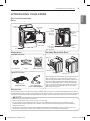 10
10
-
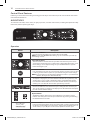 11
11
-
 12
12
-
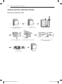 13
13
-
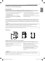 14
14
-
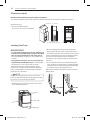 15
15
-
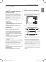 16
16
-
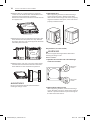 17
17
-
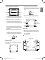 18
18
-
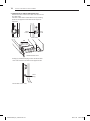 19
19
-
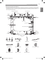 20
20
-
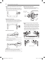 21
21
-
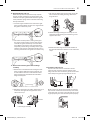 22
22
-
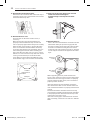 23
23
-
 24
24
-
 25
25
-
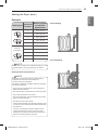 26
26
-
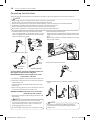 27
27
-
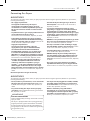 28
28
-
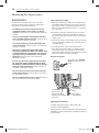 29
29
-
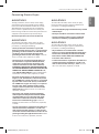 30
30
-
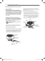 31
31
-
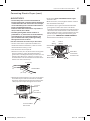 32
32
-
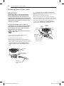 33
33
-
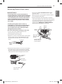 34
34
-
 35
35
-
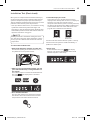 36
36
-
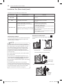 37
37
-
 38
38
-
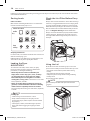 39
39
-
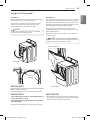 40
40
-
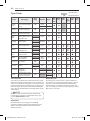 41
41
-
 42
42
-
 43
43
-
 44
44
-
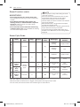 45
45
-
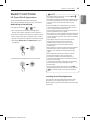 46
46
-
 47
47
-
 48
48
-
 49
49
-
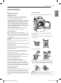 50
50
-
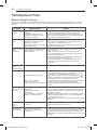 51
51
-
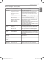 52
52
-
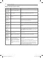 53
53
-
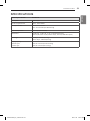 54
54
-
 55
55
-
 56
56
-
 57
57
-
 58
58
-
 59
59
-
 60
60
-
 61
61
-
 62
62
-
 63
63
-
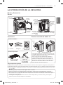 64
64
-
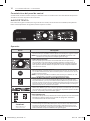 65
65
-
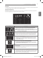 66
66
-
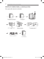 67
67
-
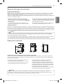 68
68
-
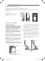 69
69
-
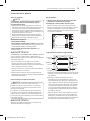 70
70
-
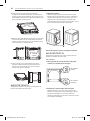 71
71
-
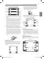 72
72
-
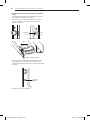 73
73
-
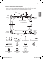 74
74
-
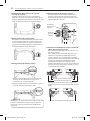 75
75
-
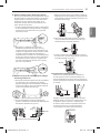 76
76
-
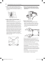 77
77
-
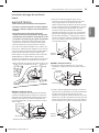 78
78
-
 79
79
-
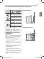 80
80
-
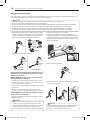 81
81
-
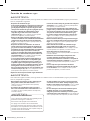 82
82
-
 83
83
-
 84
84
-
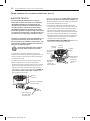 85
85
-
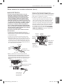 86
86
-
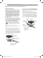 87
87
-
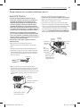 88
88
-
 89
89
-
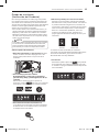 90
90
-
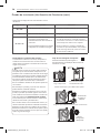 91
91
-
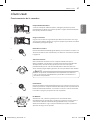 92
92
-
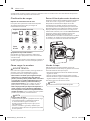 93
93
-
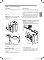 94
94
-
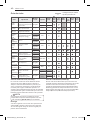 95
95
-
 96
96
-
 97
97
-
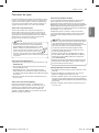 98
98
-
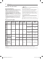 99
99
-
 100
100
-
 101
101
-
 102
102
-
 103
103
-
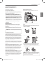 104
104
-
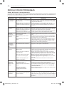 105
105
-
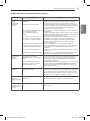 106
106
-
 107
107
-
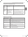 108
108
-
 109
109


LG DT30BTSG El manual del propietario
- Categoría
- Secadoras de ropa eléctricas
- Tipo
- El manual del propietario
en otros idiomas
- English: LG DT30BTSG Owner's manual
Artículos relacionados
-
LG DT22BSSG El manual del propietario
-
LG DLGX9001V El manual del propietario
-
LG DLEX9500K El manual del propietario
-
LG DF22RV2S El manual del propietario
-
LG DLGX7901BE El manual del propietario
-
-
LG DF22BV2B El manual del propietario
-
LG DF22WV2E El manual del propietario
-
LG DLE1501W El manual del propietario
-
LG DLE7200WE El manual del propietario