ATEN VE873 Guía de inicio rápido
- Categoría
- Secadoras
- Tipo
- Guía de inicio rápido

VE872/VE873/VE874/VE875 HDMI Active Optical Cable Quick Start Guide VE872/VE873/VE874/VE875 Cable HDMI activo por bra óptica Guía rápida
Câble optique actif HDMI VE872/VE873/VE874/VE875 – Guide de démarrage rapide Cavo ottico attivo HDMI VE872/VE873/VE874/VE875 – Guida rapida
VE872/VE873/VE874/VE875 Aktiver HDMI-Lichtwellenleiter Kurzanleitung Краткое руководство пользователя активного волоконно-оптического кабеля HDMI VE872/VE873/VE874/VE875
www.aten.com www.aten.com
www.aten.com www.aten.com
www.aten.com www.aten.com
Package Contents
1 VE872 / VE873 / VE874 / VE875 HDMI Active Optical Cable
1 User Instructions
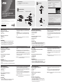
Hardware Review
A
Transmitter Front and Rear Panels
1. Power LED
2. HDMI Input Port
Receiver Front and Rear Panels
1. Power LED
2. HDMI Output Port
3. Power
Installation
B
1. Connect the HDMI connector on the VE872T/VE873T/VE874T/
VE875T to the HDMI OUT port on your video source device.
2. Connect the HDMI connector on the VE872R/VE873R/VE874R/
VE875R to the HDMI IN port on your video display device.
Presentación del hardware
A
Paneles anterior y posterior del transmisor
1. Indicador de alimentación
2. Puerto de entrada HDMI
3. Alimentación
Paneles anterior y posterior del receptor
1. Indicador de alimentación
2. Puerto de salida HDMI
3. Alimentación
Instalación
B
1. Inserte el conector HDMI del VE872T/VE873T/VE874T/VE875T en
la salida de señal HDMI de su dispositivo fuente de señal.
2. Inserte el conector HDMI del VE872R/VE873R/VE874R/VE875R en
la entrada de señal HDMI de su dispositivo de visualización.
Hardware
A
Pannelli anteriore e posteriore del trasmettitore
1. LED d’alimentazione
2. Porta d’ingresso HDMI
3. Alimentazione
Pannelli anteriore e posteriore del ricevitore
1. LED d’alimentazione
2. Porta d’uscita HDMI
3. Alimentazione
Installazione
B
1. Collegare il connettore HDMI del VE872T/VE873T/VE874T/VE875T
alla porta di uscita HDMI del dispositivo video sorgente.
2. Collegare il connettore HDMI del VE872R/VE873R/VE874R/VE875R
alla porta di ingresso HDMI del dispositivo video di visualizzazione.
Обзор оборудования
A
Лицевая и задняя панели передатчика
1. Индикатор питания
2. Вход HDMI
3. Питание
Лицевая и задняя панели приемника
1. Индикатор питания
2. Выход HDMI
3. Питание
Установка оборудования
B
1. Подключите разъем HDMI VE872T/VE873T/VE874T/VE875T к
выходу HDMI источника видео.
2. Подключите разъем HDMI VE872R/VE873R/VE874R/VE875R к
входу HDMI устройства отображения.
Description de l’appareil
A
Panneaux avant et arrière de l’émetteur
1. Voyant d’alimentation
2. Port d’entrée HDMI
3. Alimentation
Panneaux avant et arrière du récepteur
1. Voyant d’alimentation
2. Port de sortie HDMI
3. Alimentation
Installation
B
1. Branchez le connecteur HDMI du module VE872T/VE873T/VE874T/
VE875T sur le port de sortie HDMI de votre périphérique vidéo
source.
2. Branchez le connecteur HDMI du module VE872R/VE873R/VE874R/
Hardwareübersicht
A
Vorder- und Rückseite des Senders
1. LED-Betriebsanzeige
2. HDMI-Eingang
3. Stromversorgung
Vorder- und Rückseite des Empfängers
1. LED-Betriebsanzeige
2. HDMI-Ausgang
3. Stromversorgung
Installation
B
1. Verbinden Sie den HDMI-Stecker des VE872T/VE873T/VE874T/
VE875T mit dem HDMI-Ausgang Ihrer Bildsignalquelle.
3. (Optional) Connect the USB connector on the VE872T/VE873T/
VE874T/VE875T to the USB port on your video source device to
supply power.
4. Connect the USB connector on the VE872R/VE873R/VE874R/
VE875R to the USB port on your video display device to supply
power.
Note: The USB connector is removable from the Transmitter and
Receiver’s bottom panel.
3. (Opcional) Inserte el conector USB del VE872T/VE873T/VE874T/
VE875T en el puerto USB de su dispositivo fuente de señal para
suministrarle energía eléctrica.
4. Inserte el conector USB del VE872R/VE873R/VE874R/VE875R en
el puerto USB de su dispositivo de visualización para suministrarle
energía eléctrica.
Nota: El conector USB se puede retirar de la parte inferior del
transmisor y receptor.
3. (Opzionale) Collegare il connettore USB del VE872T/VE873T/
VE874T/VE875T alla porta USB del dispositivo video sorgente per
fornire l’alimentazione.
4. Collegare il connettore USB del VE872R/VE873R/VE874R/VE875R
alla porta USB del dispositivo video di visualizzazione per fornire
l’alimentazione.
Nota: è possibile rimuovere il connettore USB dal pannello inferiore del
trasmettitore o del ricevitore.
3. (Дополнительно) Подключите разъем USB VE872T/VE873T/
VE874T/VE875T к порту USB источника видео для подачи
питания.
4. Подключите разъем USB VE872R/VE873R/VE874R/VE875R к
порту USB устройства отображения для подачи питания.
Примечание. Разъем USB снимается с нижней панели передатчика
и приемника.
VE875R sur le port d’entrée HDMI de votre périphérique d’af chage
vidéo.
3. (Facultatif) Branchez le connecteur USB du module VE872T/
VE873T/VE874T/VE875T sur le port de USB de votre périphérique
vidéo source pour assurer l’alimentation.
4. Branchez le connecteur USB du module VE872R/VE873R/VE874R/
VE875R sur le port de USB de votre périphérique d’af chage vidéo
pour assurer l’alimentation.
Remarque : le connecteur USB peut être retiré du panneau inférieur
de l'émetteur et du récepteur.
2. Verbinden Sie den HDMI-Stecker des VE872R/VE873R/VE874R/
VE875R mit dem HDMI-Eingang Ihres Anzeigegerätes.
3. (Optional) Verbinden Sie den USB-Stecker des VE872T/VE873T/
VE874T/VE875T mit dem USB-Anschluss Ihrer Bildsignalquelle, um
das Gerät mit Strom zu versorgen.
4. Verbinden Sie den USB-Stecker des VE872R/VE873R/VE874R/
VE875R mit dem USB-Anschluss Ihres Anzeigegerätes, um das
Gerät mit Strom zu versorgen.
Hinweis: Der USB-Stecker lässt sich von der Unterseite des Senders
bzw. Empfängers abziehen.
AHardware Review
Transmitter Front and Rear Panels Receiver Front and Rear Panels
BInstallation
© Copyright 2015 ATEN® International Co., Ltd.
ATEN and the ATEN logo are trademarks of ATEN International Co., Ltd. All rights reserved. All
other trademarks are the property of their respective owners.
This product is RoHS compliant.
Part No. PAPE-1223-B50G Printing Date: 01/2015
HDMI Active Optical Cable
Quick Start Guide
VE872 / VE873 / VE874 / VE875
ATEN VanCryst™
2
12
1
3
HDMI Source
Device
HDMI Display
Receiver
Transmitter
2
3
1
4
Important Notice
Considering environmental protection, ATEN does not provide a fully printed user manual for this product.
If the information contained in the Quick Start Guide is not enough for you to confi gure and operate your
product, please visit our website www.aten.com, and download the full user manual.
Online Registration
http://eservice.aten.com
Technical Phone Support
International:
886-2-86926959
All information, documentation, fi rmware, software utilities, and specifi cations contained in this package are
subject to change without prior notifi cation by the manufacturer. Please visit our website http://www.aten.
com/download/?cid=dds for the most up-to-date versions.
유선 제품용 / A급 기기 (업무용 방송 통신 기기)
이 기기는 업무용(A급) 전자파적합기기로서 판매자 또는 사용자는 이점을 주의하시기 바라며, 가정 외
의 지역에서 사용하는 것을 목적으로 합니다.
EMC Information
FEDERAL COMMUNICATIONS COMMISSION INTERFERENCE STATEMENT:
This equipment has been tested and found to comply with the limits for a Class B digital service, pursuant to Part
15 of the FCC rules. These limits are designed to provide reasonable protection against harmful interference in a
residential installation. Any changes or modifi cations made to this equipment may void the user s authority to
operate this equipment. This equipment generates, uses, and can radiate radio frequency energy. If not installed and
used in accordance with the instructions, may cause harmful interference to radio communications. However, there
is no guarantee that interference will not occur in a particular installation. If this equipment does cause harmful
interference to radio or television reception, which can be determined by turning the equipment off and on, the
user is encouraged to try to correct the interference by one or more of the following measures:
- Reorient or relocate the receiving antenna;
- Increase the separation between the equipment and receiver;
- Connect the equipment into an outlet on a circuit different from that to
which the receiver is connected;
- Consult the dealer/an experienced radio/television technician for help.
FCC Caution: Any changes or modifi cations not expressly approved by the party responsible for compliance could
void the user's authority to operate this equipment.
The following contains information that relates to China:
North America:
1-888-999-ATEN Ext: 4988
United Kingdom:
44-8-4481-58923
La página se está cargando...
Transcripción de documentos
Important Notice Package Contents 1 1 A ATEN VanCryst™ B VE872 / VE873 / VE874 / VE875 HDMI Active Optical Cable User Instructions Considering environmental protection, ATEN does not provide a fully printed user manual for this product. If the information contained in the Quick Start Guide is not enough for you to configure and operate your product, please visit our website www.aten.com, and download the full user manual. Installation Online Registration http://eservice.aten.com 1 HDMI Source Device Hardware Review Transmitter Front and Rear Panels 3 1 2 Receiver 4 1 This product is RoHS compliant. VE872/VE873/VE874/VE875 HDMI Active Optical Cable Quick Start Guide 3. (Optional) Connect the USB connector on the VE872T/VE873T/ VE874T/VE875T to the USB port on your video source device to supply power. 4. Connect the USB connector on the VE872R/VE873R/VE874R/ VE875R to the USB port on your video display device to supply power. 1. Power LED 2. HDMI Input Port Receiver Front and Rear Panels 1. Power LED 2. HDMI Output Port 3. Power Installation www.aten.com Note: The USB connector is removable from the Transmitter and Receiver’s bottom panel. B A Panneaux avant et arrière de l’émetteur 1. Voyant d’alimentation 2. Port d’entrée HDMI 3. Alimentation Panneaux avant et arrière du récepteur 1. Voyant d’alimentation 2. Port de sortie HDMI 3. Alimentation Installation www.aten.com VE875R sur le port d’entrée HDMI de votre périphérique d’affichage vidéo. 3. (Facultatif) Branchez le connecteur USB du module VE872T/ VE873T/VE874T/VE875T sur le port de USB de votre périphérique vidéo source pour assurer l’alimentation. 4. Branchez le connecteur USB du module VE872R/VE873R/VE874R/ VE875R sur le port de USB de votre périphérique d’affichage vidéo pour assurer l’alimentation. Remarque : le connecteur USB peut être retiré du panneau inférieur de l'émetteur et du récepteur. B Hardwareübersicht A Vorder- und Rückseite des Senders 1. LED-Betriebsanzeige 2. HDMI-Eingang 3. Stromversorgung Vorder- und Rückseite des Empfängers 1. LED-Betriebsanzeige 2. HDMI-Ausgang 3. Stromversorgung Installation B 1. Verbinden Sie den HDMI-Stecker des VE872T/VE873T/VE874T/ VE875T mit dem HDMI-Ausgang Ihrer Bildsignalquelle. VE872/VE873/VE874/VE875 Cable HDMI activo por fibra óptica Guía rápida Presentación del hardware A Paneles anterior y posterior del transmisor 1. Indicador de alimentación 2. Puerto de entrada HDMI 3. Alimentación Paneles anterior y posterior del receptor 1. Indicador de alimentación 2. Puerto de salida HDMI 3. Alimentación www.aten.com 3. (Opcional) Inserte el conector USB del VE872T/VE873T/VE874T/ VE875T en el puerto USB de su dispositivo fuente de señal para suministrarle energía eléctrica. 4. Inserte el conector USB del VE872R/VE873R/VE874R/VE875R en el puerto USB de su dispositivo de visualización para suministrarle energía eléctrica. Nota: El conector USB se puede retirar de la parte inferior del transmisor y receptor. B Cavo ottico attivo HDMI VE872/VE873/VE874/VE875 – Guida rapida Hardware A Pannelli anteriore e posteriore del trasmettitore 1. LED d’alimentazione 2. Porta d’ingresso HDMI 3. Alimentazione Pannelli anteriore e posteriore del ricevitore 1. LED d’alimentazione 2. Porta d’uscita HDMI 3. Alimentazione Installazione www.aten.com 3. (Opzionale) Collegare il connettore USB del VE872T/VE873T/ VE874T/VE875T alla porta USB del dispositivo video sorgente per fornire l’alimentazione. 4. Collegare il connettore USB del VE872R/VE873R/VE874R/VE875R alla porta USB del dispositivo video di visualizzazione per fornire l’alimentazione. Nota: è possibile rimuovere il connettore USB dal pannello inferiore del trasmettitore o del ricevitore. B 1. Collegare il connettore HDMI del VE872T/VE873T/VE874T/VE875T alla porta di uscita HDMI del dispositivo video sorgente. 2. Collegare il connettore HDMI del VE872R/VE873R/VE874R/VE875R alla porta di ingresso HDMI del dispositivo video di visualizzazione. 1. Branchez le connecteur HDMI du module VE872T/VE873T/VE874T/ VE875T sur le port de sortie HDMI de votre périphérique vidéo source. 2. Branchez le connecteur HDMI du module VE872R/VE873R/VE874R/ VE872/VE873/VE874/VE875 Aktiver HDMI-Lichtwellenleiter Kurzanleitung 유선 제품용 / A급 기기 (업무용 방송 통신 기기) 이 기기는 업무용(A급) 전자파적합기기로서 판매자 또는 사용자는 이점을 주의하시기 바라며, 가정 외 의 지역에서 사용하는 것을 목적으로 합니다. 1. Inserte el conector HDMI del VE872T/VE873T/VE874T/VE875T en la salida de señal HDMI de su dispositivo fuente de señal. 2. Inserte el conector HDMI del VE872R/VE873R/VE874R/VE875R en la entrada de señal HDMI de su dispositivo de visualización. Câble optique actif HDMI VE872/VE873/VE874/VE875 – Guide de démarrage rapide Description de l’appareil FEDERAL COMMUNICATIONS COMMISSION INTERFERENCE STATEMENT: This equipment has been tested and found to comply with the limits for a Class B digital service, pursuant to Part 15 of the FCC rules. These limits are designed to provide reasonable protection against harmful interference in a residential installation. Any changes or modifications made to this equipment may void the user s authority to operate this equipment. This equipment generates, uses, and can radiate radio frequency energy. If not installed and used in accordance with the instructions, may cause harmful interference to radio communications. However, there is no guarantee that interference will not occur in a particular installation. If this equipment does cause harmful interference to radio or television reception, which can be determined by turning the equipment off and on, the user is encouraged to try to correct the interference by one or more of the following measures: - Reorient or relocate the receiving antenna; - Increase the separation between the equipment and receiver; - Connect the equipment into an outlet on a circuit different from that to which the receiver is connected; - Consult the dealer/an experienced radio/television technician for help. FCC Caution: Any changes or modifications not expressly approved by the party responsible for compliance could void the user's authority to operate this equipment. All information, documentation, firmware, software utilities, and specifications contained in this package are subject to change without prior notification by the manufacturer. Please visit our website http://www.aten. com/download/?cid=dds for the most up-to-date versions. Instalación 1. Connect the HDMI connector on the VE872T/VE873T/VE874T/ VE875T to the HDMI OUT port on your video source device. 2. Connect the HDMI connector on the VE872R/VE873R/VE874R/ VE875R to the HDMI IN port on your video display device. 2 HDMI Display 3 Printing Date: 01/2015 A The following contains information that relates to China: Receiver Front and Rear Panels 2 © Copyright 2015 ATEN® International Co., Ltd. ATEN and the ATEN logo are trademarks of ATEN International Co., Ltd. All rights reserved. All other trademarks are the property of their respective owners. Transmitter Front and Rear Panels United Kingdom: 44-8-4481-58923 EMC Information HDMI Active Optical Cable Quick Start Guide Hardware Review North America: 1-888-999-ATEN Ext: 4988 Transmitter VE872 / VE873 / VE874 / VE875 Part No. PAPE-1223-B50G Technical Phone Support International: 886-2-86926959 www.aten.com 2. Verbinden Sie den HDMI-Stecker des VE872R/VE873R/VE874R/ VE875R mit dem HDMI-Eingang Ihres Anzeigegerätes. 3. (Optional) Verbinden Sie den USB-Stecker des VE872T/VE873T/ VE874T/VE875T mit dem USB-Anschluss Ihrer Bildsignalquelle, um das Gerät mit Strom zu versorgen. 4. Verbinden Sie den USB-Stecker des VE872R/VE873R/VE874R/ VE875R mit dem USB-Anschluss Ihres Anzeigegerätes, um das Gerät mit Strom zu versorgen. Hinweis: Der USB-Stecker lässt sich von der Unterseite des Senders bzw. Empfängers abziehen. Краткое руководство пользователя активного волоконно-оптического кабеля HDMI VE872/VE873/VE874/VE875 Обзор оборудования A Лицевая и задняя панели передатчика 1. Индикатор питания 2. Вход HDMI 3. Питание Лицевая и задняя панели приемника 1. Индикатор питания 2. Выход HDMI 3. Питание Установка оборудования B 1. Подключите разъем HDMI VE872T/VE873T/VE874T/VE875T к выходу HDMI источника видео. 2. Подключите разъем HDMI VE872R/VE873R/VE874R/VE875R к входу HDMI устройства отображения. www.aten.com 3. (Дополнительно) Подключите разъем USB VE872T/VE873T/ VE874T/VE875T к порту USB источника видео для подачи питания. 4. Подключите разъем USB VE872R/VE873R/VE874R/VE875R к порту USB устройства отображения для подачи питания. Примечание. Разъем USB снимается с нижней панели передатчика и приемника.-
 1
1
-
 2
2


ATEN VE873 Guía de inicio rápido
- Categoría
- Secadoras
- Tipo
- Guía de inicio rápido
en otros idiomas
- français: ATEN VE873 Guide de démarrage rapide
- italiano: ATEN VE873 Guida Rapida
- English: ATEN VE873 Quick start guide
- Deutsch: ATEN VE873 Schnellstartanleitung
- русский: ATEN VE873 Инструкция по началу работы
- português: ATEN VE873 Guia rápido
- 日本語: ATEN VE873 クイックスタートガイド